Embed Size (px)
Citation preview
FHWA-NJ-2012-008
Compatibility of Highway Railroad Crossing Gates with Overhead Catenary System High Voltage Power for Trains
Final Report June 2010
Submitted by
William T. Riddell Douglas Cleary Associate Professor Associate Professor Rowan University Rowan University
Peter M. Jansson Hector Suarez Associate Professor Student Rowan University Rowan University
NJ DOT Project Manager Edward Stephen Kondrath
In cooperation with
New Jersey Department of Transportation Bureau of Research
And
U.S. Department of Transportation Federal Highway Administration
DISCLAIMER STATEMENT
The contents of this report reflect the views of the authors who are responsible for the facts and the accuracy of the data presented herein. The contents do not necessarily reflect the official views or policies of the New Jersey Department of Transportation, the Federal Highway Administration, or the New Jersey Transit Authority. This report does not constitute a standard, specification, or regulation.
iii
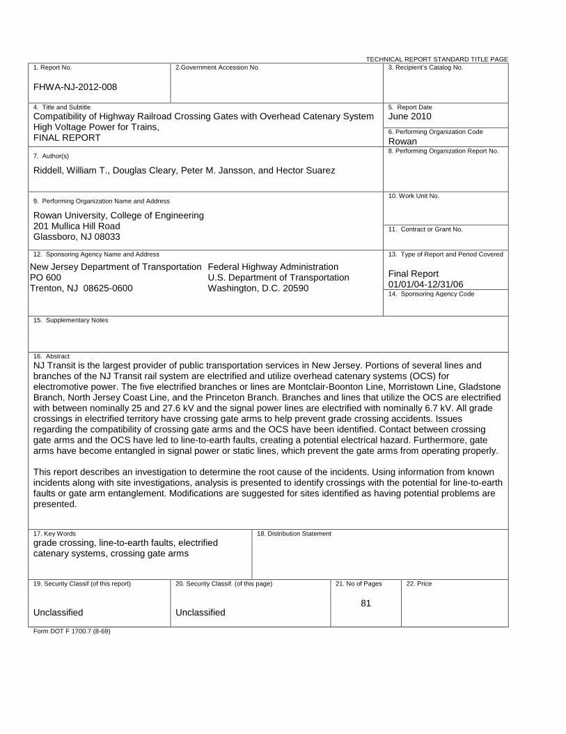
TECHNICAL REPORT STANDARD TITLE PAGE1. Report No. 2.Government Accession No. 3. Recipient’s Catalog No.
FHWA-NJ-2012-008
4. Title and Subtitle 5. Report DateCompatibility of Highway Railroad Crossing Gates with Overhead Catenary System High Voltage Power for Trains, FINAL REPORT
June 2010 6. Performing Organization CodeRowan
7. Author(s)8. Performing Organization Report No.
Riddell, William T., Douglas Cleary, Peter M. Jansson, and Hector Suarez
9. Performing Organization Name and Address10. Work Unit No.
Rowan University, College of Engineering 201 Mullica Hill Road Glassboro, NJ 08033
11. Contract or Grant No.
12. Sponsoring Agency Name and Address 13. Type of Report and Period Covered
Final Report 01/01/04-12/31/06 14. Sponsoring Agency Code
15. Supplementary Notes
16. AbstractNJ Transit is the largest provider of public transportation services in New Jersey. Portions of several lines and branches of the NJ Transit rail system are electrified and utilize overhead catenary systems (OCS) for electromotive power. The five electrified branches or lines are Montclair-Boonton Line, Morristown Line, Gladstone Branch, North Jersey Coast Line, and the Princeton Branch. Branches and lines that utilize the OCS are electrified with between nominally 25 and 27.6 kV and the signal power lines are electrified with nominally 6.7 kV. All grade crossings in electrified territory have crossing gate arms to help prevent grade crossing accidents. Issues regarding the compatibility of crossing gate arms and the OCS have been identified. Contact between crossing gate arms and the OCS have led to line-to-earth faults, creating a potential electrical hazard. Furthermore, gate arms have become entangled in signal power or static lines, which prevent the gate arms from operating properly.
This report describes an investigation to determine the root cause of the incidents. Using information from known incidents along with site investigations, analysis is presented to identify crossings with the potential for line-to-earth faults or gate arm entanglement. Modifications are suggested for sites identified as having potential problems are presented.
17. Key Words 18. Distribution Statementgrade crossing, line-to-earth faults, electrified catenary systems, crossing gate arms
19. Security Classif (of this report) 20. Security Classif. (of this page) 21. No of Pages 22. Price
Unclassified Unclassified81
Form DOT F 1700.7 (8-69)
Federal Highway Administration U.S. Department of Transportation Washington, D.C. 20590
New Jersey Department of Transportation PO 600 Trenton, NJ 08625-0600
ii
ACKNOWLEDGEMENTS
The authors wish to thank the New Jersey Department of Transportation (NJ DOT) and staff for support of this project. In particular, project manager Mr. Edward Kondrath. Also, the support of NJ Transit staff members Mr. Mark Cobert, Mr. John Vogler, and Dr. Jerome Lutin in collecting data about the system, as well as Mr. Greg Golden and Mr. Robert Milazzo for help with a failure investigation is appreciated. Finally, we would like to thank Mr. William Goodman and Mr. Phil Olekszyk.
ii
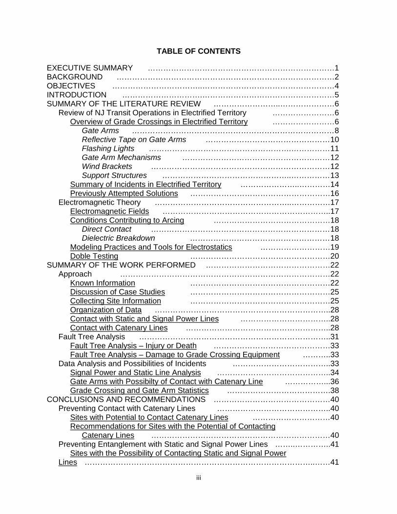
TABLE OF CONTENTS
EXECUTIVE SUMMARY ………………………………………………………………1 BACKGROUND …………………………………………………………………………2 OBJECTIVES ……………………………..……………………………………………4 INTRODUCTION ………………………….……………………………………………5 SUMMARY OF THE LITERATURE REVIEW ……………………..…………………6 Review of NJ Transit Operations in Electrified Territory ……………………6 Overview of Grade Crossings in Electrified Territory ……………………6 Gate Arms ……………………………………………………………………8 Reflective Tape on Gate Arms …………………………………………10 Flashing Lights ……………………………………………….……………11 Gate Arm Mechanisms …………………………………………………12 Wind Brackets ……………………………………………………………12 Support Structures …………………………………………..……………13 Summary of Incidents in Electrified Territory …………………..…………14 Previously Attempted Solutions ………………………………………………16 Electromagnetic Theory ……………………………………………..……………17 Electromagnetic Fields ………………………………………………………..17 Conditions Contributing to Arcing ………………………………………18 Direct Contact ……………………………………………………………18 Dielectric Breakdown ………………………………………………18 Modeling Practices and Tools for Electrostatics ………………………19 Doble Testing ………………………………………………20 SUMMARY OF THE WORK PERFORMED …………………………………………22 Approach ………………………………………………………………………22 Known Information ………………………………………………22 Discussion of Case Studies ………………………………………………25 Collecting Site Information ………………………………………………25 Organization of Data …………………………………………………………..28 Contact with Static and Signal Power Lines ……………………………..28 Contact with Catenary Lines ………………………………………………..28 Fault Tree Analysis ………………………………………………………………..31 Fault Tree Analysis – Injury or Death ………………………………………33 Fault Tree Analysis – Damage to Grade Crossing Equipment ………..33 Data Analysis and Possibilities of Incidents ………………………………..33 Signal Power and Static Line Analysis ……………………………………..34 Gate Arms with Possibilty of Contact with Catenary Line ……………...36 Grade Crossing and Gate Arm Statistics ………………………………….38 CONCLUSIONS AND RECOMMENDATIONS ………………………………………40 Preventing Contact with Catenary Lines ……………………………………..40 Sites with Potential to Contact Catenary Lines …………………………40 Recommendations for Sites with the Potential of Contacting
Catenary Lines ……………………………………………………………40 Preventing Entanglement with Static and Signal Power Lines ……..…………..41 Sites with the Possibility of Contacting Static and Signal Power
Lines ……………………………………………………………………………..……41
iii
Recommendations for Sites with Possibility of Contacting Static or Signal Power Lines ……………………..…………………………………42
Recommendations for Future Grade Crossing Design ……................................43 IMPLEMENTATION AND TRAINING ……………………………………………….44 REFERENCES …………………………………………………………………………..46 APPENDIX A – KNOWN PREVIOUS INCIDENTS ……………………………….48 APPENDIX B – CASE STUDIES …………………………………………………..49
Sycamore Ave. ……………………………………………………………………49 Station Rd. ………………………………….………………………………………55 Chelsea And 5th Ave. – Incident on 2/4/2006 ……………………………….58 APPENDIX C – RESULTS OF DOBLE TESTING ………………………………….63 APPENDIX D – CROSSINGS WITH POSSIBILITY OF TOUCHING LINES …….69 Gladstone Branch …………………………………………………………………..69 Montclaire-Boonton Line …………………………………………………………..69 Morristown Line ……………………………………………………………………70
Princeton Branch ..............................................................................................70 NJCL ……………………………………………………………………………….71
iv
LIST OF FIGURES
Figure 1. NJ Transit rail system ……………………………………………………..3 Figure 2. Overhead view of Chelsea and 5th Ave. crossing ………………………..6 Figure 3. Ground view of crossing …………………………………………………….7 Figure 4. Schematic illustration of support structure …………………………………7 Figure 5. Schematic illustration of lines ……………………………………………….8 Figure 6. Gate arm in upright position ……………………………………………….8 Figure 7. Gate arm lifting mechanism ………………………………………………….9 Figure 8. Schematic of telescoping gate arm sections ……………………………….9 Figure 9. Definitions of cross sectional dimensions ………………………………….10 Figure 10. Schematic of cross section for reflective tape …………………………….11 Figure 11. Pedestrian crossing gate arm with typical configuration of
flashing lights ………………………………………………………………….12 Figure 12. Wind bracket, wind bracket mast, and crossing gate arm at the
Broad Street crossing on the NJCL ………………………………………….13 Figure 13. Support structure near Freighthouse Road on the Gladstone
branch …………………………………………………………………………………..13 Figure 14. Support structure near Claremont Avenue on the Montclair-
Boonton line …………………………………………………………………………..14 Figure 15. Gate saver …………………………………………………………………..16 Figure 16. Insulated power lines at the Westwood Ave. crossing on the
NJCL ……………………………………………………………………………….17 Figure 17. Three electrode Doble test configuration ……………………………….21 Figure 18. Summary of comments on records for previous incidents …………….24 Figure 19. Summary of known wire contact incidents. Ambiguous records
are ignored. …………………………………………………………………………24 Figure 20. Incidents involving contact with catenary lines over time ……………..25 Figure 21. Calculations using the Pythagorean Theorem ………………..30 Figure 22. Plan view for calculating the angle needed to contact the
catenary line. ………………………………………………………….30 Figure 23. Fault tree – injury or death ……………………………………………..32 Figure 24. Fault tree – damage to grade crossing equipment …………………….32 Figure 25. Statistics of crossings with possibility for contact between gate
arm and line …………………………………………………………………………38 Figure 26. Statistics of gate arms with possibility for contact with lines …………..39 Figure 27. Schematic wiring for push-button switch ……………………………….44 Figure 28. Schematic wiring for time delay switch ……………………………….45 Figure 29. Satellite image of Sycamore Ave. crossing ……………………………...50 Figure 30. NW crossing gate ………………………………………………………….51 Figure 31. NW crossing gate arm and mechanism ………………………………52 Figure 32. Wires for flashing lights on NW gate arm ………………………………53 Figure 33. Crossing gate arm at SE corner …………..……………………………….54 Figure 34. Satellite image of Station Rd. crossing …………………………………55 Figure 35. Support structure to the south of Station Rd. crossing ……………….56 Figure 36. Northern crossing gate …………………………………………………..57 Figure 37. Eastern crossing gate …………………………………………………….57
v
Figure 38. Southern crossing gate and support structure …………………………58 Figure 39. Screen shot of incident report for 2/4/2006 …………………………….58 Figure 40. Damaged gate arm, flashing light unit, and copper wire ……………….60 Figure 41. Damaged relay ……………………………………………………………60 Figure 42. Damaged fuse ……………………………………………………………61 Figure 43. Damaged resistor …………………………………………………………..61 Figure 44. Internal damage to gate arm mechanism ……………………………….62 Figure 45. Doble testing of crossing gate arm ………………………………………..64
vi
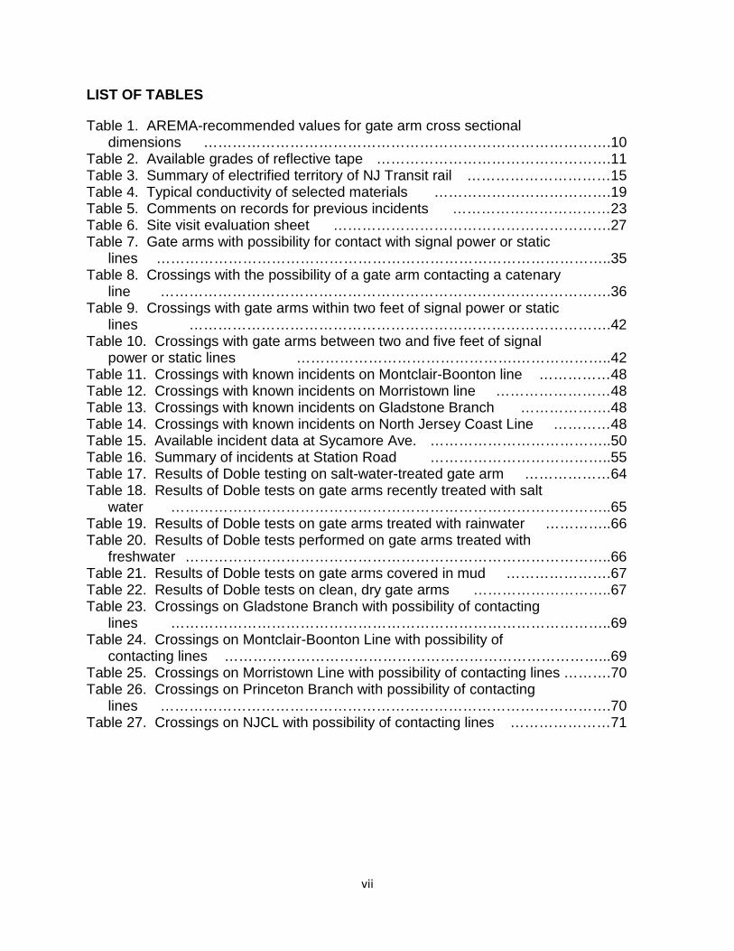
LIST OF TABLES
Table 1. AREMA-recommended values for gate arm cross sectional dimensions ………………………………………………………………………….10
Table 2. Available grades of reflective tape ………………………………………….11 Table 3. Summary of electrified territory of NJ Transit rail …………………………15 Table 4. Typical conductivity of selected materials ……………………………….19 Table 5. Comments on records for previous incidents ……………………………23 Table 6. Site visit evaluation sheet ………………………………………………….27 Table 7. Gate arms with possibility for contact with signal power or static
lines …………………………………………………………………………………..35 Table 8. Crossings with the possibility of a gate arm contacting a catenary
line ………………………………………………………………………………….36 Table 9. Crossings with gate arms within two feet of signal power or static
lines …………………………………………………………………………….42 Table 10. Crossings with gate arms between two and five feet of signal
power or static lines ……………………………………….………………..42 Table 11. Crossings with known incidents on Montclair-Boonton line ……………48 Table 12. Crossings with known incidents on Morristown line ……………………48 Table 13. Crossings with known incidents on Gladstone Branch ……………….48 Table 14. Crossings with known incidents on North Jersey Coast Line …………48 Table 15. Available incident data at Sycamore Ave. ………………………………..50 Table 16. Summary of incidents at Station Road ………………………………..55 Table 17. Results of Doble testing on salt-water-treated gate arm ………………64 Table 18. Results of Doble tests on gate arms recently treated with salt
water ………………………………………………………………………………..65 Table 19. Results of Doble tests on gate arms treated with rainwater …………..66 Table 20. Results of Doble tests performed on gate arms treated with
freshwater ……………………………………………………………………………..66 Table 21. Results of Doble tests on gate arms covered in mud ………………….67 Table 22. Results of Doble tests on clean, dry gate arms ………………………..67 Table 23. Crossings on Gladstone Branch with possibility of contacting
lines ………………………………………………………………………………..69 Table 24. Crossings on Montclair-Boonton Line with possibility of
contacting lines ……………………………………………………………………...69 Table 25. Crossings on Morristown Line with possibility of contacting lines ……….70 Table 26. Crossings on Princeton Branch with possibility of contacting
lines ………………………………………………………………………………….70 Table 27. Crossings on NJCL with possibility of contacting lines …………………71
vii
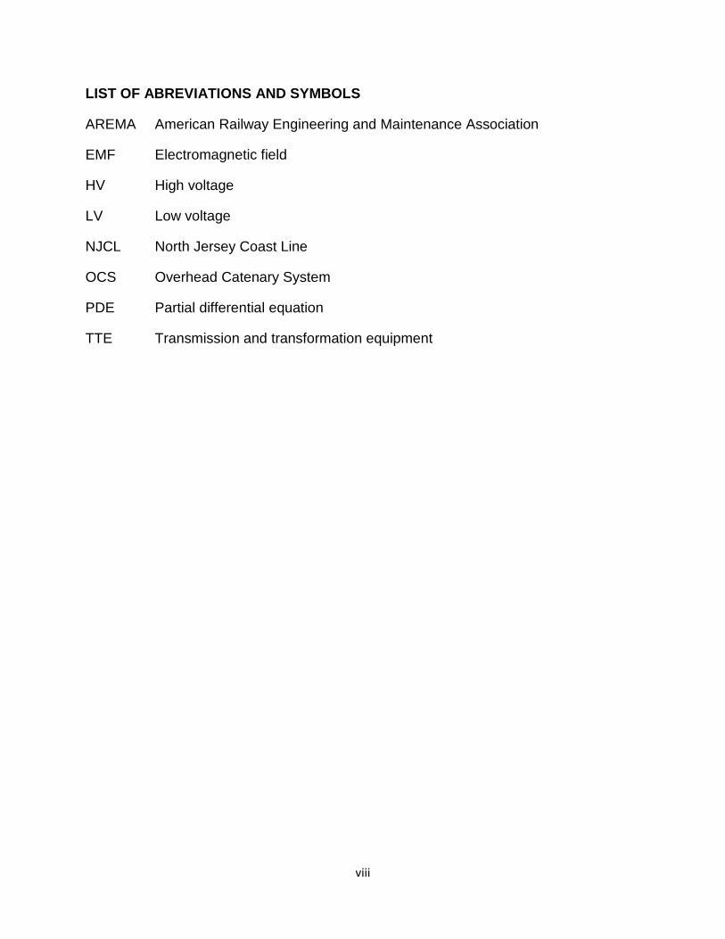
LIST OF ABREVIATIONS AND SYMBOLS
AREMA American Railway Engineering and Maintenance Association
EMF Electromagnetic field
HV High voltage
LV Low voltage
NJCL North Jersey Coast Line
OCS Overhead Catenary System
PDE Partial differential equation
TTE Transmission and transformation equipment
viii
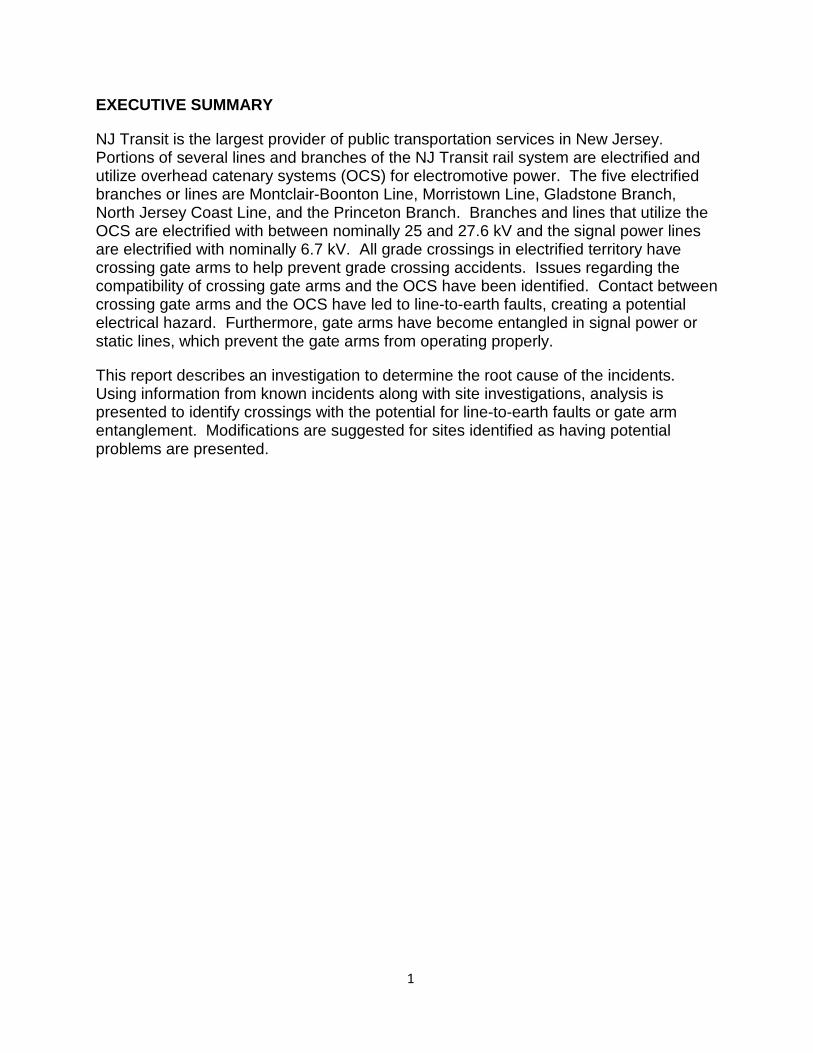
EXECUTIVE SUMMARY
NJ Transit is the largest provider of public transportation services in New Jersey. Portions of several lines and branches of the NJ Transit rail system are electrified and utilize overhead catenary systems (OCS) for electromotive power. The five electrified branches or lines are Montclair-Boonton Line, Morristown Line, Gladstone Branch, North Jersey Coast Line, and the Princeton Branch. Branches and lines that utilize the OCS are electrified with between nominally 25 and 27.6 kV and the signal power lines are electrified with nominally 6.7 kV. All grade crossings in electrified territory have crossing gate arms to help prevent grade crossing accidents. Issues regarding the compatibility of crossing gate arms and the OCS have been identified. Contact between crossing gate arms and the OCS have led to line-to-earth faults, creating a potential electrical hazard. Furthermore, gate arms have become entangled in signal power or static lines, which prevent the gate arms from operating properly.
This report describes an investigation to determine the root cause of the incidents. Using information from known incidents along with site investigations, analysis is presented to identify crossings with the potential for line-to-earth faults or gate arm entanglement. Modifications are suggested for sites identified as having potential problems are presented.
1. 1
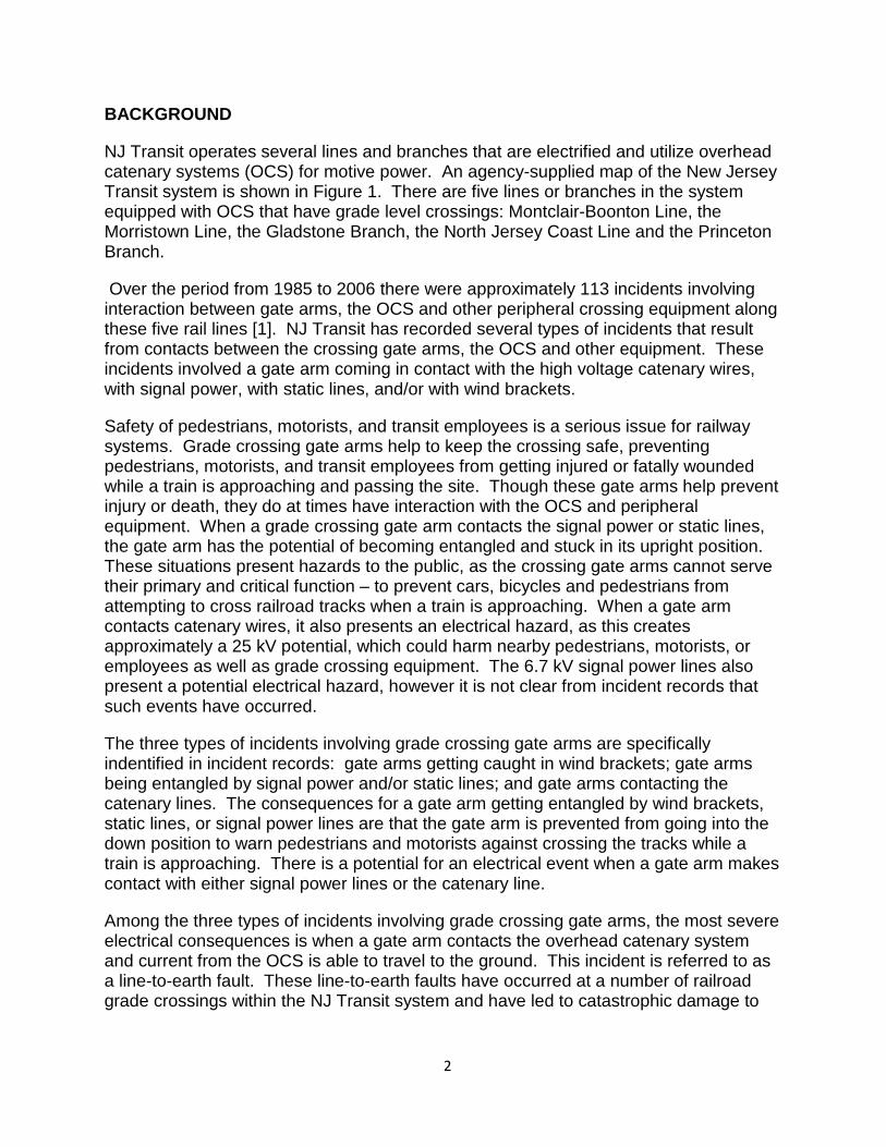
BACKGROUND
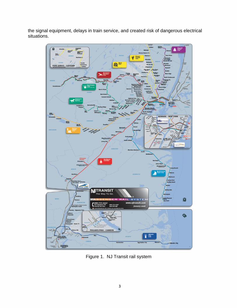
NJ Transit operates several lines and branches that are electrified and utilize overhead catenary systems (OCS) for motive power. An agency-supplied map of the New Jersey Transit system is shown in Figure 1. There are five lines or branches in the system equipped with OCS that have grade level crossings: Montclair-Boonton Line, the Morristown Line, the Gladstone Branch, the North Jersey Coast Line and the Princeton Branch.
Over the period from 1985 to 2006 there were approximately 113 incidents involving interaction between gate arms, the OCS and other peripheral crossing equipment along these five rail lines [1]. NJ Transit has recorded several types of incidents that result from contacts between the crossing gate arms, the OCS and other equipment. These incidents involved a gate arm coming in contact with the high voltage catenary wires, with signal power, with static lines, and/or with wind brackets.
Safety of pedestrians, motorists, and transit employees is a serious issue for railway systems. Grade crossing gate arms help to keep the crossing safe, preventing pedestrians, motorists, and transit employees from getting injured or fatally wounded while a train is approaching and passing the site. Though these gate arms help prevent injury or death, they do at times have interaction with the OCS and peripheral equipment. When a grade crossing gate arm contacts the signal power or static lines, the gate arm has the potential of becoming entangled and stuck in its upright position. These situations present hazards to the public, as the crossing gate arms cannot serve their primary and critical function – to prevent cars, bicycles and pedestrians from attempting to cross railroad tracks when a train is approaching. When a gate arm contacts catenary wires, it also presents an electrical hazard, as this creates approximately a 25 kV potential, which could harm nearby pedestrians, motorists, or employees as well as grade crossing equipment. The 6.7 kV signal power lines also present a potential electrical hazard, however it is not clear from incident records that such events have occurred.
The three types of incidents involving grade crossing gate arms are specifically indentified in incident records: gate arms getting caught in wind brackets; gate arms being entangled by signal power and/or static lines; and gate arms contacting the catenary lines. The consequences for a gate arm getting entangled by wind brackets, static lines, or signal power lines are that the gate arm is prevented from going into the down position to warn pedestrians and motorists against crossing the tracks while a train is approaching. There is a potential for an electrical event when a gate arm makes contact with either signal power lines or the catenary line.
Among the three types of incidents involving grade crossing gate arms, the most severe electrical consequences is when a gate arm contacts the overhead catenary system and current from the OCS is able to travel to the ground. This incident is referred to as a line-to-earth fault. These line-to-earth faults have occurred at a number of railroad grade crossings within the NJ Transit system and have led to catastrophic damage to
1. 2
the signal equipment, delays in train service, and created risk of dangerous electrical situations.
Figure 1. NJ Transit rail system
1. 3
OBJECTIVES
The objectives of this study are to identify root causes of incidents, and to develop cost-effective recommendations for NJ Transit to implement that will prevent future contact between gate arms and OCS. Secondary objectives are to make recommendations that will reduce the incidents where the crossing gate arm becomes entangled in static or signal power lines. Because the overall safety of the entire system must be improved, solutions must not adversely affect the primary job of the crossing gates: warning pedestrians and motorists of approaching trains.
1. 4
INTRODUCTION
Grade crossing sites are analyzed through the use of a fault tree. The fault tree provides a systematic analysis of all incidents that have occurred or have the possibility of occurring. The fault tree can be used to determine if a gate arm could possibly contact any wire and provides either a modification or solution for the site to be “cleared.” Future recommendations of grade crossing design parameters are also proposed to prevent future incidents from occurring.
The Summary of the Literature Review provides descriptions of NJ Transit’s electrified grade crossings; a discussion of known incidents (based on available NJ Transit data); and electromagnetic theory related to line-to-earth faults. The Summary of the Work Performed describes the approach used in this work; discussion of the fault trees developed for incidents; and the results of analyses to identify crossing gate arms with the possibility of touching signal power, static, or catenary lines. Conclusions and Recommendations discusses recommendations for potential cost effective solutions that minimize the risk of having an incident with gate arms contacting the static, signal power, and catenary lines. Specific gates with the possibility of touching lines are specified.
1. 5
SUMMARY OF THE LITERTURE REVIEW
The literature review focuses on three aspects of the problem. First, NJ Transit operations and equipment in electrified territory are identified. Next, known incidents are identified. Finally, electromagnetic theory, as it pertains to line-to-earth faults, is reviewed.
Review of NJ Transit Operations in Electrified Territory
This subsection provides an overview of the NJ Transit electrified grade crossings. Within this description, relevant equipment at electrified grade crossings is discussed. A history of known incidents, provided by NJ Transit [1] is also presented in Appendix A.
Overview of Grade Crossings in Electrified Territory
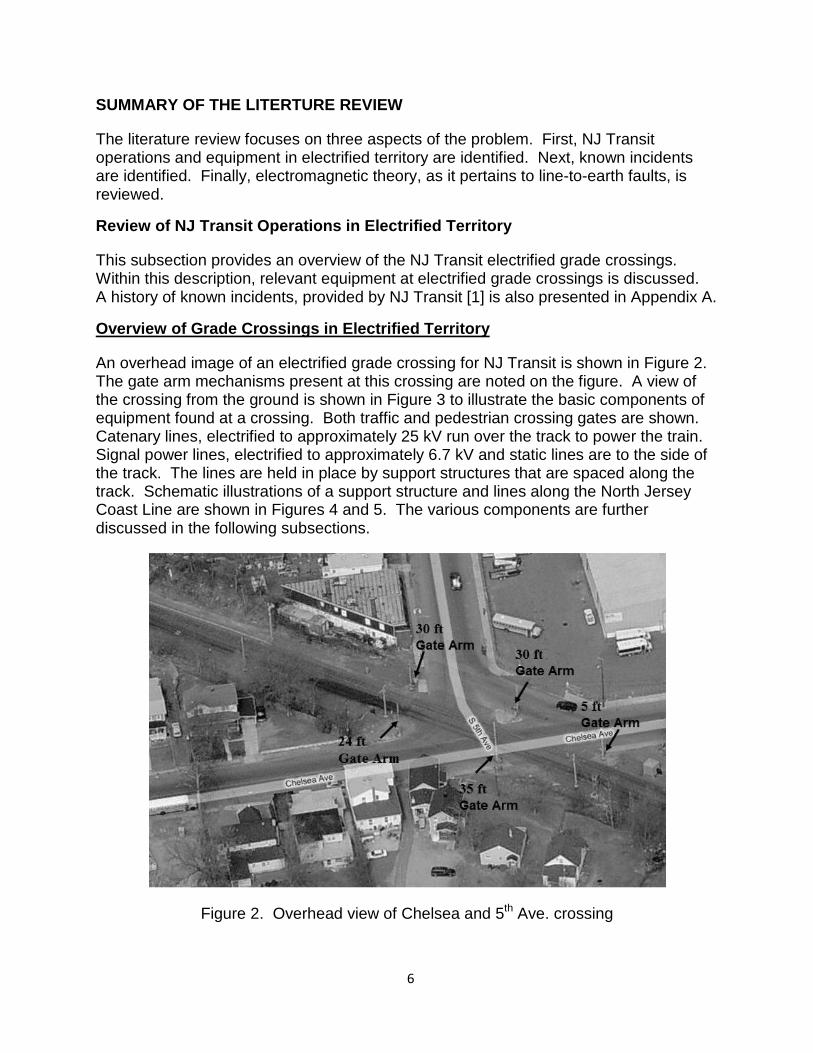
An overhead image of an electrified grade crossing for NJ Transit is shown in Figure 2. The gate arm mechanisms present at this crossing are noted on the figure. A view of the crossing from the ground is shown in Figure 3 to illustrate the basic components of equipment found at a crossing. Both traffic and pedestrian crossing gates are shown. Catenary lines, electrified to approximately 25 kV run over the track to power the train. Signal power lines, electrified to approximately 6.7 kV and static lines are to the side of the track. The lines are held in place by support structures that are spaced along the track. Schematic illustrations of a support structure and lines along the North Jersey Coast Line are shown in Figures 4 and 5. The various components are further discussed in the following subsections.
Figure 2. Overhead view of Chelsea and 5th Ave. crossing
1. 6
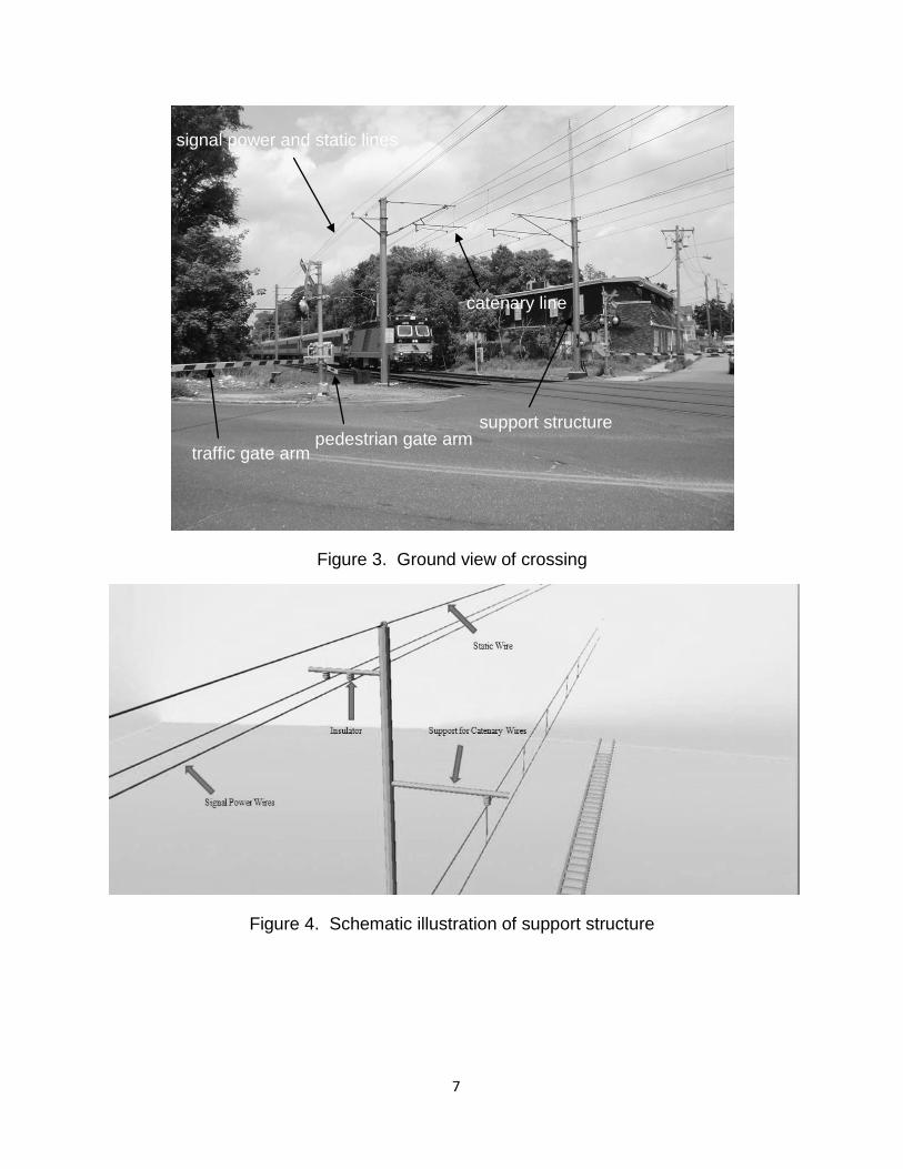
Figure 3. Ground view of crossing
Figure 4. Schematic illustration of support structure
traffic gate arm pedestrian gate arm
catenary line
signal power and static lines
support structure
1. 7
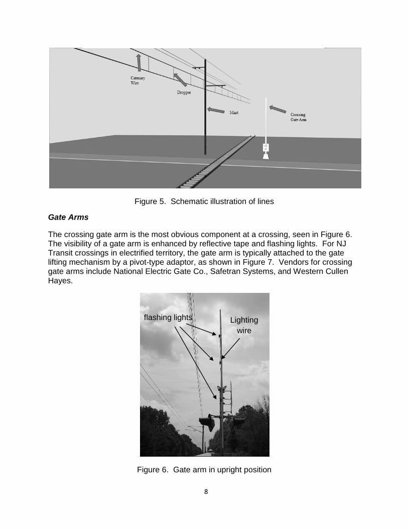
Figure 5. Schematic illustration of lines
Gate Arms
The crossing gate arm is the most obvious component at a crossing, seen in Figure 6. The visibility of a gate arm is enhanced by reflective tape and flashing lights. For NJ Transit crossings in electrified territory, the gate arm is typically attached to the gate lifting mechanism by a pivot-type adaptor, as shown in Figure 7. Vendors for crossing gate arms include National Electric Gate Co., Safetran Systems, and Western Cullen Hayes.
Figure 6. Gate arm in upright position
flashing lights Lighting wire
1. 8
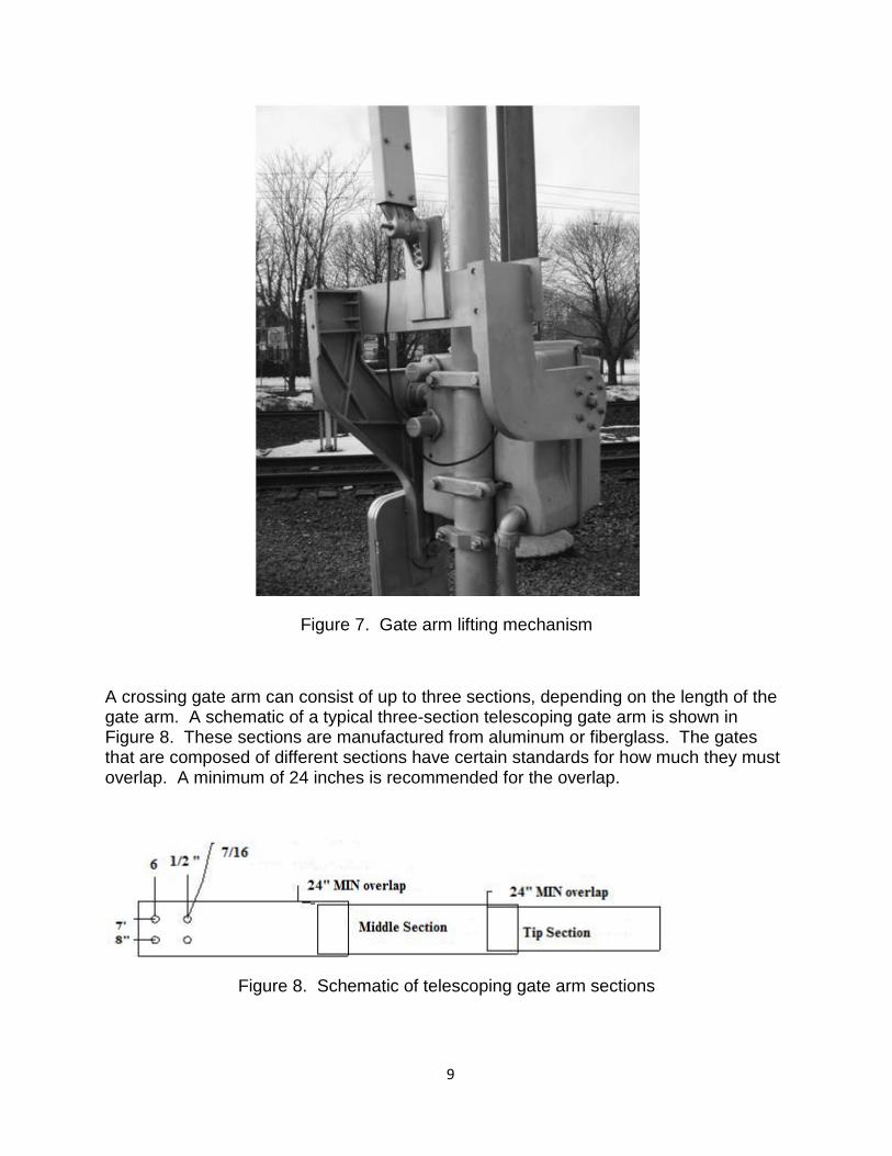
Figure 7. Gate arm lifting mechanism
A crossing gate arm can consist of up to three sections, depending on the length of the gate arm. A schematic of a typical three-section telescoping gate arm is shown in Figure 8. These sections are manufactured from aluminum or fiberglass. The gates that are composed of different sections have certain standards for how much they must overlap. A minimum of 24 inches is recommended for the overlap.
Figure 8. Schematic of telescoping gate arm sections
1. 9
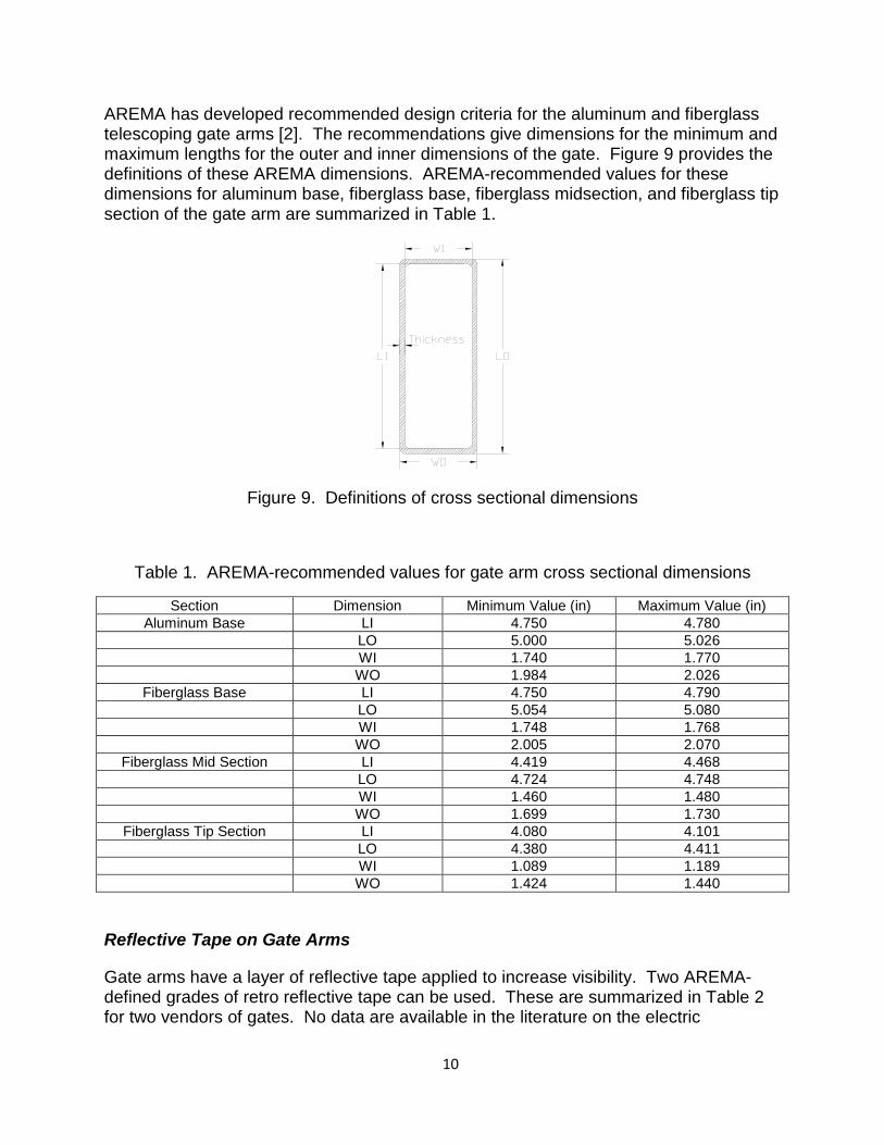
AREMA has developed recommended design criteria for the aluminum and fiberglass telescoping gate arms [2]. The recommendations give dimensions for the minimum and maximum lengths for the outer and inner dimensions of the gate. Figure 9 provides the definitions of these AREMA dimensions. AREMA-recommended values for these dimensions for aluminum base, fiberglass base, fiberglass midsection, and fiberglass tip section of the gate arm are summarized in Table 1.
Figure 9. Definitions of cross sectional dimensions
Table 1. AREMA-recommended values for gate arm cross sectional dimensions
Section Dimension Minimum Value (in) Maximum Value (in) Aluminum Base LI 4.750 4.780
LO 5.000 5.026 WI 1.740 1.770 WO 1.984 2.026
Fiberglass Base LI 4.750 4.790 LO 5.054 5.080 WI 1.748 1.768 WO 2.005 2.070
Fiberglass Mid Section LI 4.419 4.468 LO 4.724 4.748 WI 1.460 1.480 WO 1.699 1.730
Fiberglass Tip Section LI 4.080 4.101 LO 4.380 4.411 WI 1.089 1.189 WO 1.424 1.440
Reflective Tape on Gate Arms
Gate arms have a layer of reflective tape applied to increase visibility. Two AREMA-defined grades of retro reflective tape can be used. These are summarized in Table 2 for two vendors of gates. No data are available in the literature on the electric
1. 10
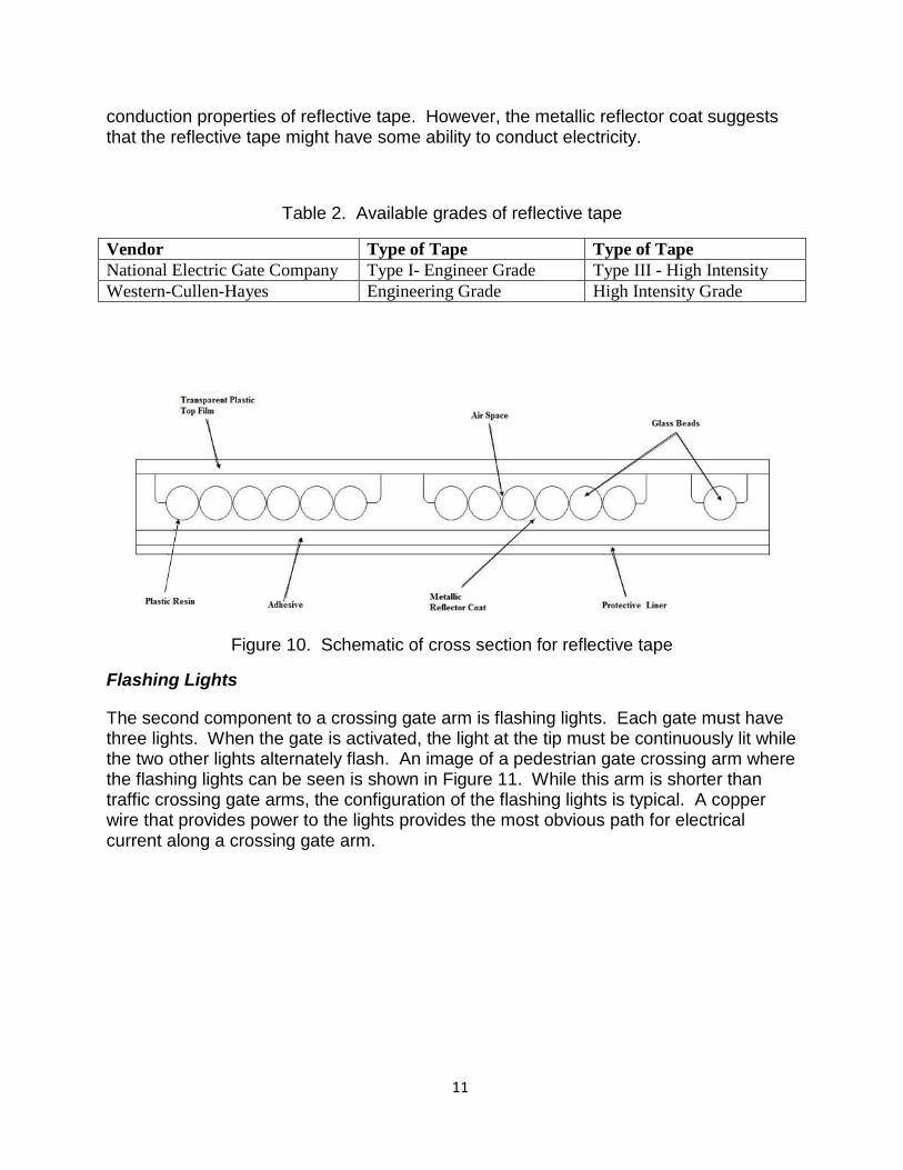
conduction properties of reflective tape. However, the metallic reflector coat suggests that the reflective tape might have some ability to conduct electricity.
Table 2. Available grades of reflective tape
Vendor Type of Tape Type of Tape National Electric Gate Company Type I- Engineer Grade Type III - High Intensity Western-Cullen-Hayes Engineering Grade High Intensity Grade
Figure 10. Schematic of cross section for reflective tape
Flashing Lights
The second component to a crossing gate arm is flashing lights. Each gate must have three lights. When the gate is activated, the light at the tip must be continuously lit while the two other lights alternately flash. An image of a pedestrian gate crossing arm where the flashing lights can be seen is shown in Figure 11. While this arm is shorter than traffic crossing gate arms, the configuration of the flashing lights is typical. A copper wire that provides power to the lights provides the most obvious path for electrical current along a crossing gate arm.
1. 11
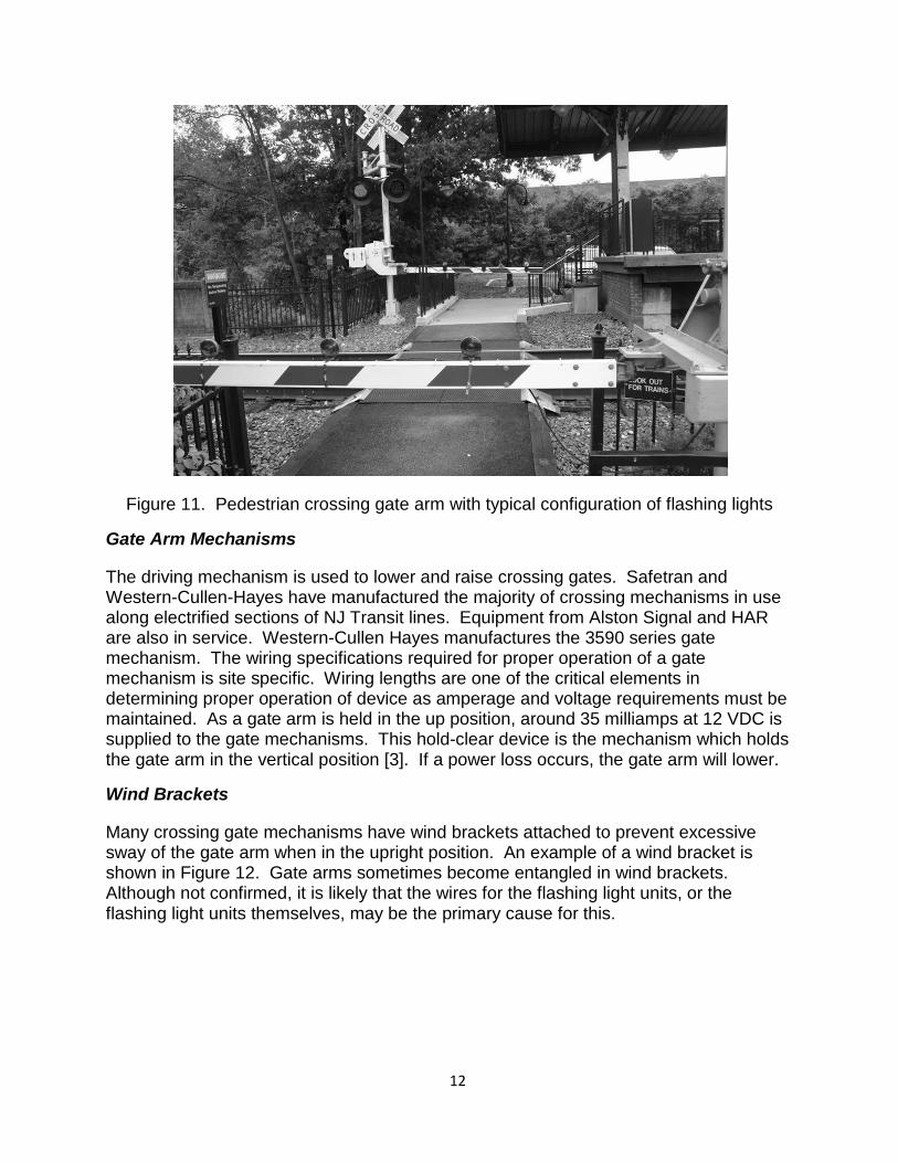
Figure 11. Pedestrian crossing gate arm with typical configuration of flashing lights
Gate Arm Mechanisms
The driving mechanism is used to lower and raise crossing gates. Safetran and Western-Cullen-Hayes have manufactured the majority of crossing mechanisms in use along electrified sections of NJ Transit lines. Equipment from Alston Signal and HAR are also in service. Western-Cullen Hayes manufactures the 3590 series gate mechanism. The wiring specifications required for proper operation of a gate mechanism is site specific. Wiring lengths are one of the critical elements in determining proper operation of device as amperage and voltage requirements must be maintained. As a gate arm is held in the up position, around 35 milliamps at 12 VDC is supplied to the gate mechanisms. This hold-clear device is the mechanism which holds the gate arm in the vertical position [3]. If a power loss occurs, the gate arm will lower.
Wind Brackets
Many crossing gate mechanisms have wind brackets attached to prevent excessive sway of the gate arm when in the upright position. An example of a wind bracket is shown in Figure 12. Gate arms sometimes become entangled in wind brackets. Although not confirmed, it is likely that the wires for the flashing light units, or the flashing light units themselves, may be the primary cause for this.
1. 12
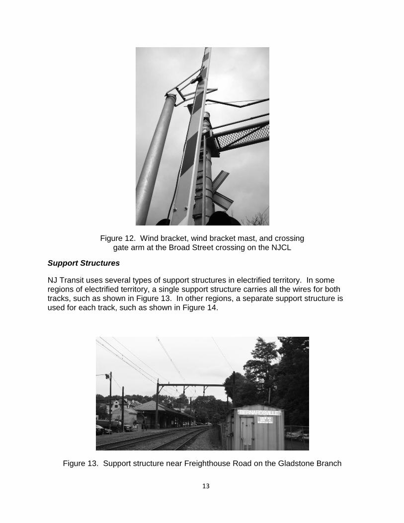
Figure 12. Wind bracket, wind bracket mast, and crossing gate arm at the Broad Street crossing on the NJCL
Support Structures
NJ Transit uses several types of support structures in electrified territory. In some regions of electrified territory, a single support structure carries all the wires for both tracks, such as shown in Figure 13. In other regions, a separate support structure is used for each track, such as shown in Figure 14.
Figure 13. Support structure near Freighthouse Road on the Gladstone Branch
1. 13
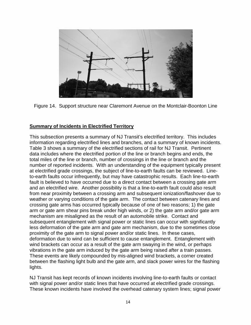
Figure 14. Support structure near Claremont Avenue on the Montclair-Boonton Line
Summary of Incidents in Electrified Territory
This subsection presents a summary of NJ Transit’s electrified territory. This includes information regarding electrified lines and branches, and a summary of known incidents. Table 3 shows a summary of the electrified sections of rail for NJ Transit. Pertinent data includes where the electrified portion of the line or branch begins and ends, the total miles of the line or branch, number of crossings in the line or branch and the number of reported incidents. With an understanding of the equipment typically present at electrified grade crossings, the subject of line-to-earth faults can be reviewed. Line-to-earth faults occur infrequently, but may have catastrophic results. Each line-to-earth fault is believed to have occurred due to a direct contact between a crossing gate arm and an electrified wire. Another possibility is that a line-to-earth fault could also result from near proximity between a crossing arm and subsequent ionization/flashover due to weather or varying conditions of the gate arm. The contact between catenary lines and crossing gate arms has occurred typically because of one of two reasons; 1) the gate arm or gate arm shear pins break under high winds, or 2) the gate arm and/or gate arm mechanism are misaligned as the result of an automobile strike. Contact and subsequent entanglement with signal power or static lines can occur with significantly less deformation of the gate arm and gate arm mechanism, due to the sometimes close proximity of the gate arm to signal power and/or static lines. In these cases, deformation due to wind can be sufficient to cause entanglement. Entanglement with wind brackets can occur as a result of the gate arm swaying in the wind, or perhaps vibrations in the gate arm induced by the gate arm being raised after a train passes. These events are likely compounded by mis-aligned wind brackets, a corner created between the flashing light bulb and the gate arm, and slack power wires for the flashing lights.
NJ Transit has kept records of known incidents involving line-to-earth faults or contact with signal power and/or static lines that have occurred at electrified grade crossings. These known incidents have involved the overhead catenary system lines; signal power
1. 14
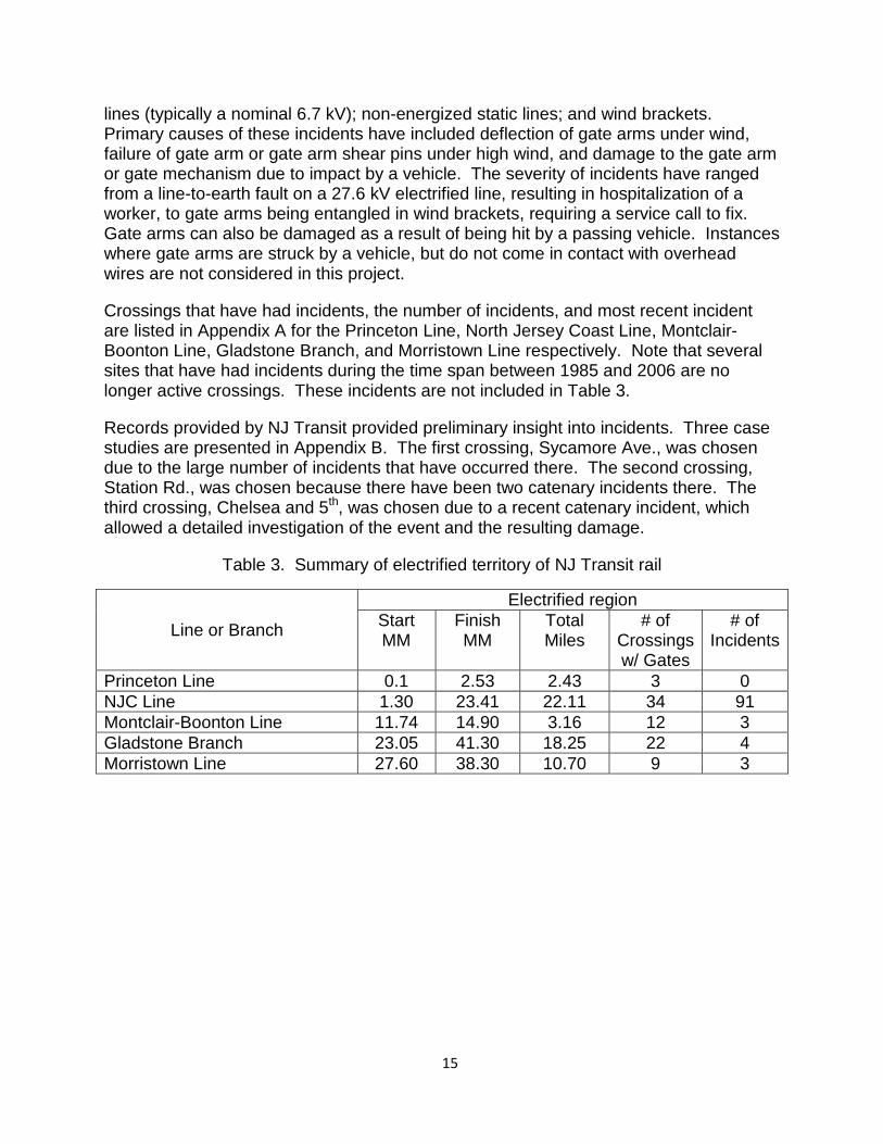
lines (typically a nominal 6.7 kV); non-energized static lines; and wind brackets. Primary causes of these incidents have included deflection of gate arms under wind, failure of gate arm or gate arm shear pins under high wind, and damage to the gate arm or gate mechanism due to impact by a vehicle. The severity of incidents have ranged from a line-to-earth fault on a 27.6 kV electrified line, resulting in hospitalization of a worker, to gate arms being entangled in wind brackets, requiring a service call to fix. Gate arms can also be damaged as a result of being hit by a passing vehicle. Instances where gate arms are struck by a vehicle, but do not come in contact with overhead wires are not considered in this project.
Crossings that have had incidents, the number of incidents, and most recent incident are listed in Appendix A for the Princeton Line, North Jersey Coast Line, Montclair-Boonton Line, Gladstone Branch, and Morristown Line respectively. Note that several sites that have had incidents during the time span between 1985 and 2006 are no longer active crossings. These incidents are not included in Table 3.
Records provided by NJ Transit provided preliminary insight into incidents. Three case studies are presented in Appendix B. The first crossing, Sycamore Ave., was chosen due to the large number of incidents that have occurred there. The second crossing, Station Rd., was chosen because there have been two catenary incidents there. The third crossing, Chelsea and 5th, was chosen due to a recent catenary incident, which allowed a detailed investigation of the event and the resulting damage.
Table 3. Summary of electrified territory of NJ Transit rail
Line or Branch
Electrified region Start MM
Finish MM
Total Miles
# of Crossings w/ Gates
# of Incidents
Princeton Line 0.1 2.53 2.43 3 0 NJC Line 1.30 23.41 22.11 34 91 Montclair-Boonton Line 11.74 14.90 3.16 12 3 Gladstone Branch 23.05 41.30 18.25 22 4 Morristown Line 27.60 38.30 10.70 9 3
1. 15
Previously Attempted Solutions
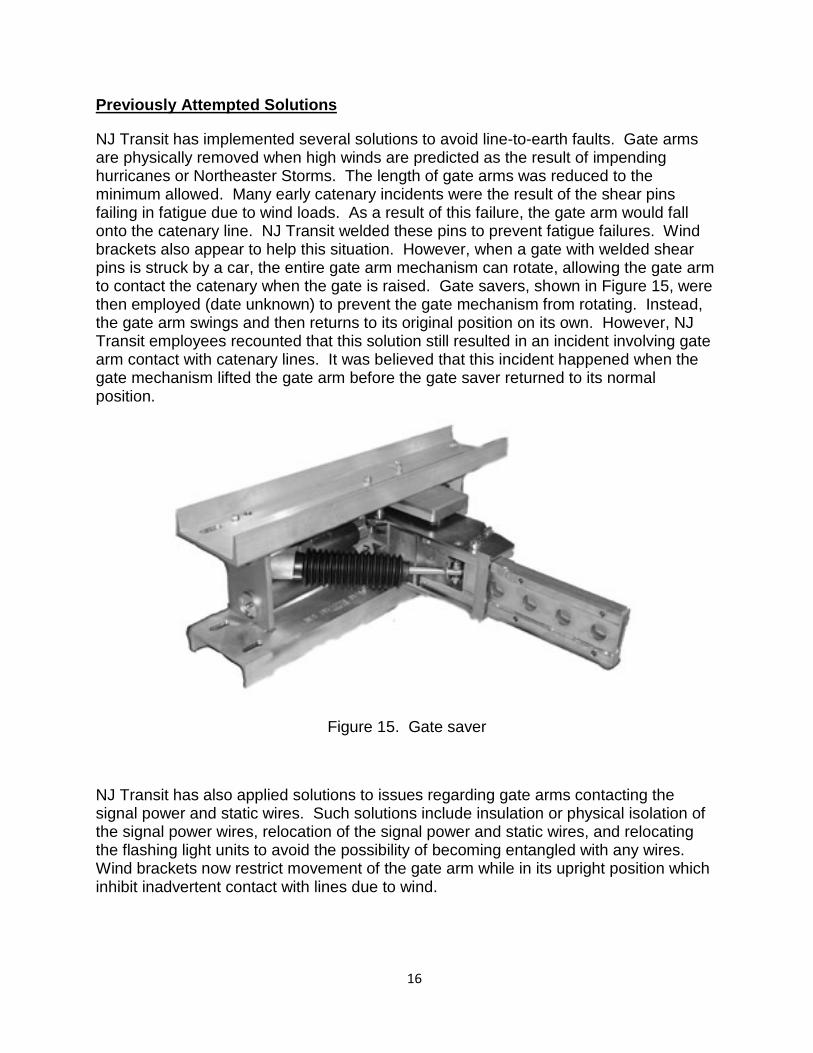
NJ Transit has implemented several solutions to avoid line-to-earth faults. Gate arms are physically removed when high winds are predicted as the result of impending hurricanes or Northeaster Storms. The length of gate arms was reduced to the minimum allowed. Many early catenary incidents were the result of the shear pins failing in fatigue due to wind loads. As a result of this failure, the gate arm would fall onto the catenary line. NJ Transit welded these pins to prevent fatigue failures. Wind brackets also appear to help this situation. However, when a gate with welded shear pins is struck by a car, the entire gate arm mechanism can rotate, allowing the gate arm to contact the catenary when the gate is raised. Gate savers, shown in Figure 15, were then employed (date unknown) to prevent the gate mechanism from rotating. Instead, the gate arm swings and then returns to its original position on its own. However, NJ Transit employees recounted that this solution still resulted in an incident involving gate arm contact with catenary lines. It was believed that this incident happened when the gate mechanism lifted the gate arm before the gate saver returned to its normal position.
Figure 15. Gate saver
NJ Transit has also applied solutions to issues regarding gate arms contacting the signal power and static wires. Such solutions include insulation or physical isolation of the signal power wires, relocation of the signal power and static wires, and relocating the flashing light units to avoid the possibility of becoming entangled with any wires. Wind brackets now restrict movement of the gate arm while in its upright position which inhibit inadvertent contact with lines due to wind.
1. 16
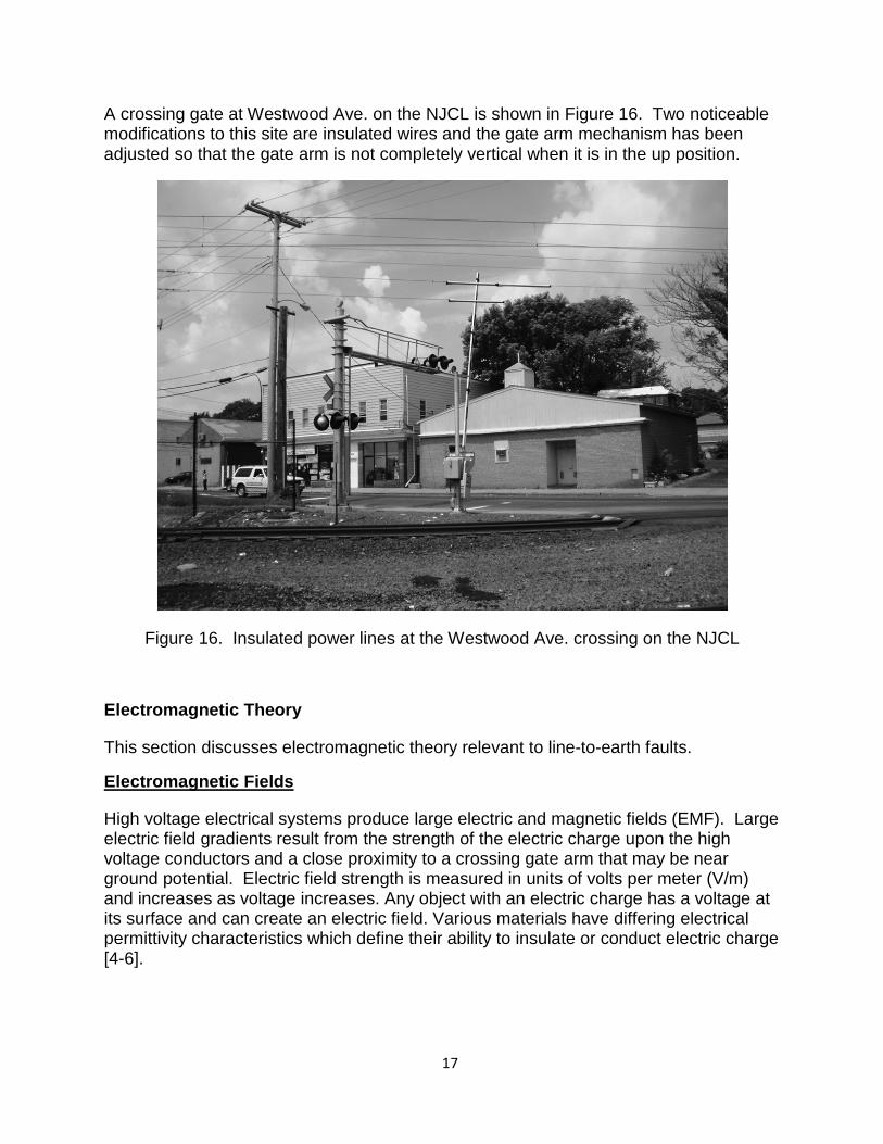
A crossing gate at Westwood Ave. on the NJCL is shown in Figure 16. Two noticeable modifications to this site are insulated wires and the gate arm mechanism has been adjusted so that the gate arm is not completely vertical when it is in the up position.
Figure 16. Insulated power lines at the Westwood Ave. crossing on the NJCL
Electromagnetic Theory
This section discusses electromagnetic theory relevant to line-to-earth faults.
Electromagnetic Fields
High voltage electrical systems produce large electric and magnetic fields (EMF). Large electric field gradients result from the strength of the electric charge upon the high voltage conductors and a close proximity to a crossing gate arm that may be near ground potential. Electric field strength is measured in units of volts per meter (V/m) and increases as voltage increases. Any object with an electric charge has a voltage at its surface and can create an electric field. Various materials have differing electrical permittivity characteristics which define their ability to insulate or conduct electric charge [4-6].
1. 17
Conditions Contributing to Arcing
EMFs are generated by the overhead contact system, as well as the signal power lines. Under normal and safe operation of the electrical system for NJ Transit, insulators keep the high voltage conductors well away from metallic supporting structures. The atmosphere acts as an insulator between the energized 25- 27.6 kV lines, the signal power lines and earth. Due to its strong dielectric properties over normal clearance distances, the air behaves in a non-ionizing fashion and remains predominantly a good insulator. Flashover conditions can occur between electrified lines and gate crossing arms under at least three specific conditions: direct contact, dielectric breakdown, and environmental effects on clearance and dielectric properties.
Direct Contact
Although fiberglass itself it typically thought of as a non-conductor, the electrical wiring that powers the flashing light units is an excellent conductor. The presence of moisture, air pollutants, salt deposits, etc., on inside and outside surfaces of the gate arms can also increase surface conductance [7]. Testing of gate arms with moisture and surface deposits are described in Appendix C. Flashover can occur along the surface of most materials at distances very much smaller than across the open space of air [8].
Dielectric Breakdown
When a large electric field is applied to an insulator it can be suddenly transformed from a good insulator into a very favorable conductor [9-11]. This results when the field strength becomes sufficient over the small distance to separate the electrons from some gas molecules in the air. These electrons are then free to ionize other gas molecules through impact. This avalanche breakdown ionization of the air is a well known [12], yet chaotic process.
If a crossing gate arm comes into very close proximity with the energized conductor, overall resistance between the conductor and ground can be reduced. In fact, this reduction could cause the dielectric withstand voltage of the air combined with the small creepage distance along the fiberglass crossing arm surface to become insufficient to insulate the 25-27.6 kV lines. The result would be that an arc forms to bridge the gap across the intervening space between the crossing gate arm and the conductor and follows a path to ground, usually the electrical wiring for the flashing light units. Typical distances for dielectric breakdown can be significantly altered if there are pointed surfaces or edges on either the energized conductor wire or the ground potential device.
There are at least three significant environmental effects that potentially have a strong impact on the underlying physical parameters that maintain the dielectric insulation properties of the air and the fiberglass crossing gate arm which normally prevent a flashover or arcing condition. These environmental effects are wind, rain and air pollutants. Wind has the ability to significantly reduce safe clearance distances since it can cause physical displacement on the part of the strung primary conductor as well as the elevated crossing gate arm. The relative motion between these two elements can significantly reduce the spacing distance between them and potentially even cause
1. 18
direct contact. Even in the absence of a direct contact the dielectric breakdown of air described above can more easily occur if wind brings the crossing gate arm within the critical distance. This critical distance can be much larger if corona effects exist.
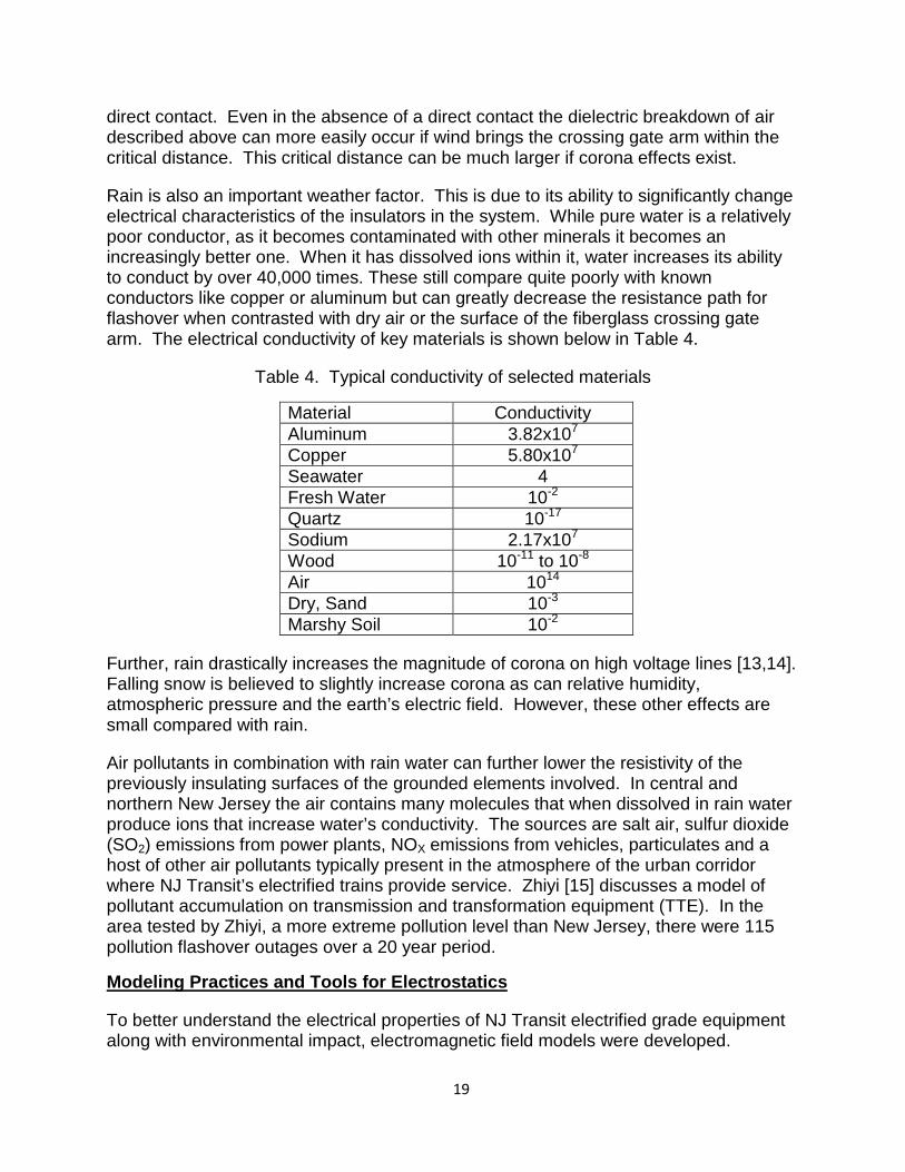
Rain is also an important weather factor. This is due to its ability to significantly change electrical characteristics of the insulators in the system. While pure water is a relatively poor conductor, as it becomes contaminated with other minerals it becomes an increasingly better one. When it has dissolved ions within it, water increases its ability to conduct by over 40,000 times. These still compare quite poorly with known conductors like copper or aluminum but can greatly decrease the resistance path for flashover when contrasted with dry air or the surface of the fiberglass crossing gate arm. The electrical conductivity of key materials is shown below in Table 4.
Table 4. Typical conductivity of selected materials
Material Conductivity Aluminum 3.82x10⁷ Copper 5.80x10⁷ Seawater 4 Fresh Water 10-2 Quartz 10-17 Sodium 2.17x10⁷ Wood 10-11 to 10-8 Air 1014 Dry, Sand 10-3 Marshy Soil 10-2
Further, rain drastically increases the magnitude of corona on high voltage lines [13,14]. Falling snow is believed to slightly increase corona as can relative humidity, atmospheric pressure and the earth’s electric field. However, these other effects are small compared with rain.
Air pollutants in combination with rain water can further lower the resistivity of the previously insulating surfaces of the grounded elements involved. In central and northern New Jersey the air contains many molecules that when dissolved in rain water produce ions that increase water’s conductivity. The sources are salt air, sulfur dioxide (SO2) emissions from power plants, NOX emissions from vehicles, particulates and a host of other air pollutants typically present in the atmosphere of the urban corridor where NJ Transit’s electrified trains provide service. Zhiyi [15] discusses a model of pollutant accumulation on transmission and transformation equipment (TTE). In the area tested by Zhiyi, a more extreme pollution level than New Jersey, there were 115 pollution flashover outages over a 20 year period.
Modeling Practices and Tools for Electrostatics
To better understand the electrical properties of NJ Transit electrified grade equipment along with environmental impact, electromagnetic field models were developed.
1. 19
Matlab’s Partial Differential Equation (PDE) Toolbox [16] is one of the many tools that can be used to model EMF. The PDE Toolbox was implemented to model the EMF around the auxiliary wires and the gate crossing arm. The model incorporates the material properties of the wires as well as the gate arm.
Along with the properties of the auxiliary wires and the gate arm, the properties of the wiring attached to the gate arm used for lighting was also incorporated into the model due to the copper in the wiring. The copper in the wiring will cause the EMF to change and distort. The effect on partial discharge characteristics inherently leads to an effect on the EMF occurring around the auxiliary wires. This inherent effect increases the critical safe distance between the gate arm and the auxiliary wires required for preventing a dielectric breakdown.
The premise of the model was to bring the gate arm in the vicinity of the auxiliary wires, not just in ideal conditions, but actual conditions seen in the field as well. Using the aforementioned conditions provided an opportunity to observe what happens to the critical distance needed for a line-to-earth fault to occur. Developing a detailed model of the EMF from line-to-earth faults provides an increased depth of insight into the occurrence of arcing as the grade crossing gate arm comes closer to the 25 kV electrified catenary wires. Methods have been developed to model the magnetic field by a two dimensional computation approach that involves transmission lines and gives both conductor-based and phase-based line parameters as well as magnetic field [17]. Several models have presented the effects of electromagnetic interference of exterior devices due to signals traveling down high power line carrier channels.
Doble Testing
Due to wear and tear and weather such as snow fall or moist air, the gate arm may not act as an insulator, but rather a conductor. This will render certain proposed solutions ineffective as the result of the fiberglass gate arm becoming a path to ground. Verification of the gate arm properties is required to validate several proposed solutions.
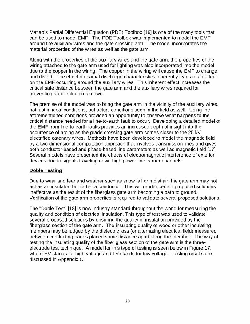
The "Doble Test" [18] is now industry standard throughout the world for measuring the quality and condition of electrical insulation. This type of test was used to validate several proposed solutions by ensuring the quality of insulation provided by the fiberglass section of the gate arm. The insulating quality of wood or other insulating members may be judged by the dielectric loss (or alternating electrical field) measured between conducting bands placed some distance apart along the member. The way of testing the insulating quality of the fiber glass section of the gate arm is the three-electrode test technique. A model for this type of testing is seen below in Figure 17, where HV stands for high voltage and LV stands for low voltage. Testing results are discussed in Appendix C.
1. 20
Figure 17. Three electrode Doble test configuration
1. 21
SUMMARY OF THE WORK PERFORMED
A summary of the work performed is discussed in three subsections. First, the overall approach is defined. Second, fault trees are defined for the various types of incidents. Finally, an analysis is performed to identify sites that might require remediation.
Approach
This section discusses the methodology used in the investigation of the incidents occurring at the railroad crossing sites in NJ Transit’s electrified railway lines and branches. The methodology begins by obtaining and analyzing all incidents that occurred prior to the beginning of the investigation. Upon developing a basic understanding of prior incidents and probable future incidents, a site visit was made to every electrified crossing within NJ Transit’s territory to perform measurements, record observations, and obtain any other pertinent information. Details of the information collected during the site visits are discussed in a later section.
Three distinct types of events are considered in these analyses: contact with the signal power wires and static wires, entanglement with wind brackets, and contact with catenary wires. An analysis of each site was performed based on field observations, and independent of known incidents. Each gate arm was assessed for the possibility of contacting static lines, signal power lines, and catenary lines. Every gate arm with the possibility of contacting one or more lines has been identified.
Known Information
To begin the investigation, NJ Transit provided data regarding general electrified grade crossing sites, such as the number of gate arms present at each site, along with the respective height of each gate arm [19,20]. Included with a list of previous known incidents that occurred from 1985 to 2006 were comments pertaining to each incident describing in general what had occurred. Table 5 displays a summary list of the comments that were provided. Note that many records are ambiguous. Incidents at sites that are no longer active grade crossings are included in this table. As such, incident totals from Table 5 do not exactly match those from Table 3.
Figure 18 graphically summarizes Table 5. The most common reason for a reported incident is “gate in wires.” Gate in wires is ambiguous but eliminates the possibility of being caught in wind brackets. The next most common reason involves gate arm getting caught in a wind bracket which in turn eliminates the possibility of contact with signal power, static, and catenary lines.
Figure 19 shows the frequency of crossing gate arms coming in contact with the catenary, signal power, and static lines. The data used to create this chart are extracted from incidents where the specific type of line was identified within NJ Transits comments. Reports where the specific line involved in contact was not identified are ignored in this figure. Although contact with static lines and signal power lines occur more frequently, in general, their impact is not as severe as when gate arms contact catenary lines.
1. 22
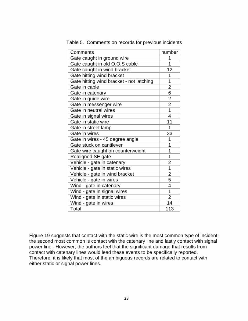
Table 5. Comments on records for previous incidents
Comments number Gate caught in ground wire 1 Gate caught in old O.O.S cable 1 Gate caught in wind bracket 12 Gate hitting wind bracket 1 Gate hitting wind bracket - not latching 1 Gate in cable 2 Gate in catenary 6 Gate in guide wire 2 Gate in messenger wire 2 Gate in neutral wires 1 Gate in signal wires 4 Gate in static wire 11 Gate in street lamp 1 Gate in wires 33 Gate in wires - 45 degree angle 1 Gate stuck on cantilever 1 Gate wire caught on counterweight 1 Realigned SE gate 1 Vehicle - gate in catenary 2 Vehicle - gate in static wires 1 Vehicle - gate in wind bracket 2 Vehicle - gate in wires 5 Wind - gate in catenary 4 Wind - gate in signal wires 1 Wind - gate in static wires 2 Wind - gate in wires 14 Total 113
Figure 19 suggests that contact with the static wire is the most common type of incident; the second most common is contact with the catenary line and lastly contact with signal power line. However, the authors feel that the significant damage that results from contact with catenary lines would lead these events to be specifically reported. Therefore, it is likely that most of the ambiguous records are related to contact with either static or signal power lines.
1. 23
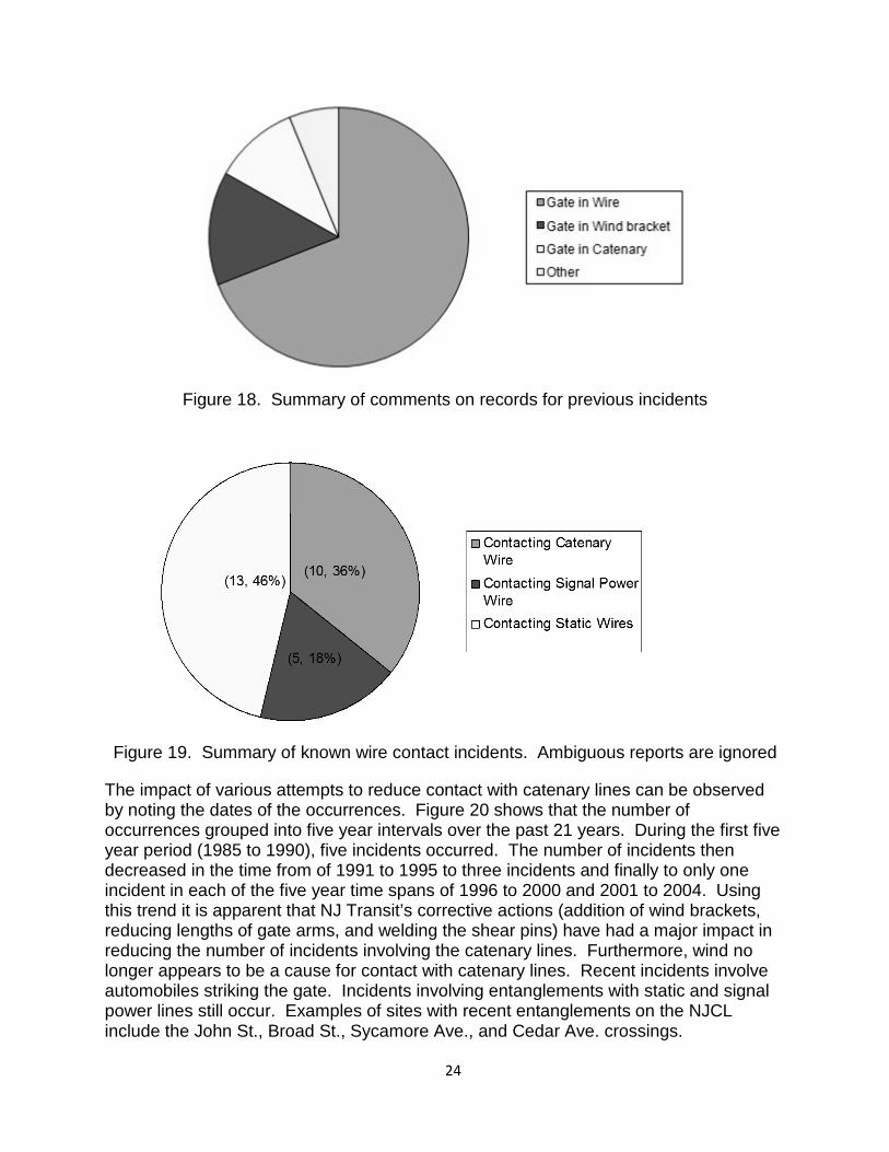
Figure 18. Summary of comments on records for previous incidents
Figure 19. Summary of known wire contact incidents. Ambiguous reports are ignored
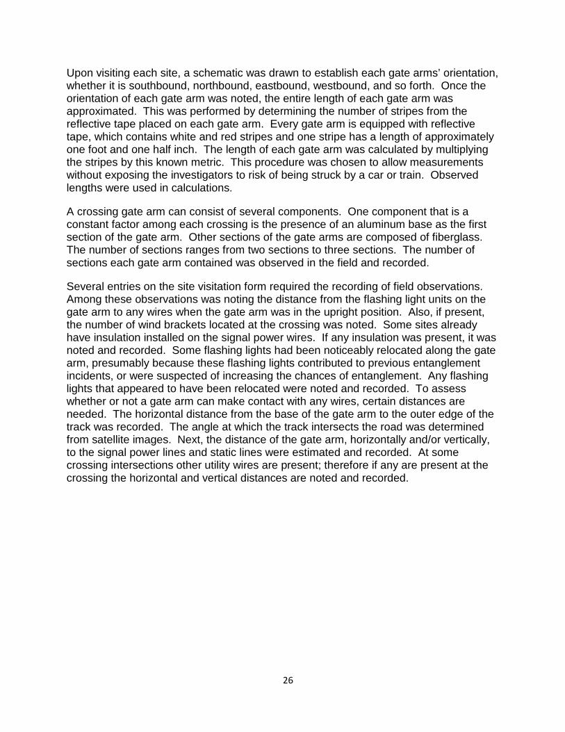
The impact of various attempts to reduce contact with catenary lines can be observed by noting the dates of the occurrences. Figure 20 shows that the number of occurrences grouped into five year intervals over the past 21 years. During the first five year period (1985 to 1990), five incidents occurred. The number of incidents then decreased in the time from of 1991 to 1995 to three incidents and finally to only one incident in each of the five year time spans of 1996 to 2000 and 2001 to 2004. Using this trend it is apparent that NJ Transit’s corrective actions (addition of wind brackets, reducing lengths of gate arms, and welding the shear pins) have had a major impact in reducing the number of incidents involving the catenary lines. Furthermore, wind no longer appears to be a cause for contact with catenary lines. Recent incidents involve automobiles striking the gate. Incidents involving entanglements with static and signal power lines still occur. Examples of sites with recent entanglements on the NJCL include the John St., Broad St., Sycamore Ave., and Cedar Ave. crossings.
1. 24
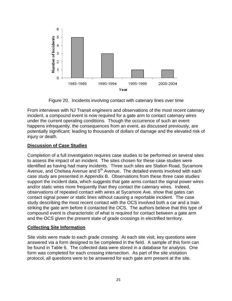
Figure 20. Incidents involving contact with catenary lines over time
From interviews with NJ Transit engineers and observations of the most recent catenary incident, a compound event is now required for a gate arm to contact catenary wires under the current operating conditions. Though the occurrence of such an event happens infrequently, the consequences from an event, as discussed previously, are potentially significant: leading to thousands of dollars of damage and the elevated risk of injury or death.
Discussion of Case Studies
Completion of a full investigation requires case studies to be performed on several sites to assess the impact of an incident. The sites chosen for these case studies were identified as having had many incidents. Three such sites are Station Road, Sycamore Avenue, and Chelsea Avenue and 5th Avenue. The detailed events involved with each case study are presented in Appendix B. Observations from these three case studies support the incident data, which suggests that gate arms contact the signal power wires and/or static wires more frequently than they contact the catenary wires. Indeed, observations of repeated contact with wires at Sycamore Ave. show that gates can contact signal power or static lines without causing a reportable incident. The case study describing the most recent contact with the OCS involved both a car and a train striking the gate arm before it contacted the OCS. The authors believe that this type of compound event is characteristic of what is required for contact between a gate arm and the OCS given the present state of grade crossings in electrified territory.
Collecting Site Information
Site visits were made to each grade crossing. At each site visit, key questions were answered via a form designed to be completed in the field. A sample of this form can be found in Table 6. The collected data were stored in a database for analysis. One form was completed for each crossing intersection. As part of the site visitation protocol, all questions were to be answered for each gate arm present at the site.
1. 25
Upon visiting each site, a schematic was drawn to establish each gate arms’ orientation, whether it is southbound, northbound, eastbound, westbound, and so forth. Once the orientation of each gate arm was noted, the entire length of each gate arm was approximated. This was performed by determining the number of stripes from the reflective tape placed on each gate arm. Every gate arm is equipped with reflective tape, which contains white and red stripes and one stripe has a length of approximately one foot and one half inch. The length of each gate arm was calculated by multiplying the stripes by this known metric. This procedure was chosen to allow measurements without exposing the investigators to risk of being struck by a car or train. Observed lengths were used in calculations.
A crossing gate arm can consist of several components. One component that is a constant factor among each crossing is the presence of an aluminum base as the first section of the gate arm. Other sections of the gate arms are composed of fiberglass. The number of sections ranges from two sections to three sections. The number of sections each gate arm contained was observed in the field and recorded.
Several entries on the site visitation form required the recording of field observations. Among these observations was noting the distance from the flashing light units on the gate arm to any wires when the gate arm was in the upright position. Also, if present, the number of wind brackets located at the crossing was noted. Some sites already have insulation installed on the signal power wires. If any insulation was present, it was noted and recorded. Some flashing lights had been noticeably relocated along the gate arm, presumably because these flashing lights contributed to previous entanglement incidents, or were suspected of increasing the chances of entanglement. Any flashing lights that appeared to have been relocated were noted and recorded. To assess whether or not a gate arm can make contact with any wires, certain distances are needed. The horizontal distance from the base of the gate arm to the outer edge of the track was recorded. The angle at which the track intersects the road was determined from satellite images. Next, the distance of the gate arm, horizontally and/or vertically, to the signal power lines and static lines were estimated and recorded. At some crossing intersections other utility wires are present; therefore if any are present at the crossing the horizontal and vertical distances are noted and recorded.
1. 26
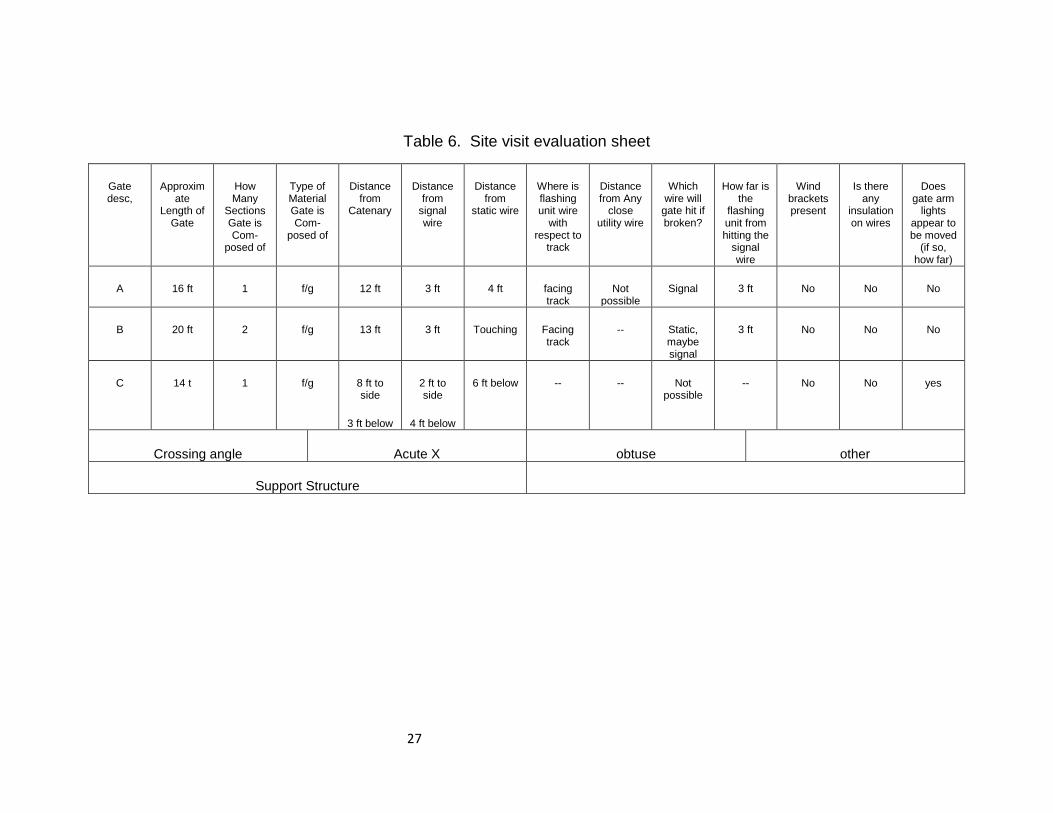
Table 6. Site visit evaluation sheet
Gate desc,
Approximate
Length of Gate
How Many
Sections Gate is Com-
posed of
Type of Material Gate is Com-
posed of
Distance from
Catenary
Distance from
signal wire
Distance from
static wire
Where is flashing unit wire
with respect to
track
Distance from Any
close utility wire
Which wire will
gate hit if broken?
How far is the
flashing unit from hitting the
signal wire
Wind brackets present
Is there any
insulation on wires
Does gate arm
lights appear to be moved
(if so, how far)
A 16 ft 1 f/g 12 ft 3 ft 4 ft facing track
Not possible
Signal 3 ft No No No
B 20 ft 2 f/g 13 ft 3 ft Touching Facing track
-- Static, maybe signal
3 ft No No No
C 14 t 1 f/g 8 ft to side
3 ft below
2 ft to side
4 ft below
6 ft below -- -- Not possible
-- No No yes
Crossing angle Acute X obtuse other
Support Structure
1. 27
Organization of Data
The data for each grade crossing were entered into a database. Calculations were completed which determined whether or not a gate arm could possibly contact the catenary lines. Sites that have gate arms observed to be either lower than all the lines or beneath the signal power, static, and catenary lines were deemed ‘not at risk’ and removed from further investigation.
The approach to evaluating the possibility for contact with static wires and signal power lines began with a visual inspection. If the gate arm in the upright position has a portion of its length rising above nearby static and signal power lines, then it was considered possible for the gate arm to contact the line. This approach allowed for rapid elimination of gate arms exhibiting no possibility for contact with static and signal power lines from further investigation.
Contact with Static and Signal Power Lines
Based on NJ Transit knowledge of prior incidents and site visits performed during this study, the occurrence of a crossing gate arm having contact with a static or signal power line can occur quite often. However, contact is not sufficient to cause a reportable incident. To cause a reportable incident, some aspect of the gate arm must become entangled, thereby preventing the gate from lowering properly. Such an event requires a service call and has an impact on safety because the gate arm will not protect motorists and pedestrians in the manner it was intended to. There is an additional potential for a line-to-earth fault if a gate arm contacts a signal power line, although there are no reports that clearly indicate this event has occurred. The primary cause for reportable incidents with signal power lines is the gate arm being tangled, with no mention of electrical problem.
If a crossing gate arm, in its upright position, extends above the static line or signal power line, then it is identified as having the possibility of contacting the line. Each crossing gate arm with a possibility of contact with a line is placed into the appropriate bin, based on horizontal distances of zero to two feet, two to four feet, four to six feet, or six feet and higher.
Contact with Catenary Lines
Contact with catenary lines can occur along NJ Transit’s electrified railroad territory. There are relatively few instances of this event that have been specifically recorded as the gate arm hitting the catenary. While there are many records where the line that was involved in the incident was not clearly denoted, the authors feel that the catastrophic consequences of a gate arm touching the catenary line would lead to the catenary line being specifically mentioned in the report when this happens. However, the infrequent occurrence does not mitigate the potential severe consequences. It appears that in most cases the resulting cascading fault is significant with possible damage to the gate arm, gate mechanism, components within the housing cabinet of controls for the crossing, and even posing risk of injury or death to any nearby pedestrians, workers, or motorists.
1. 28
The most notable fact derived from data on previous incidents is that the factor of wind moving the gate arm into contact with the catenary wires has been removed by NJ Transit actions. The frequency of these incidents declines over time, with only two events occurring over the decade from 1996 to 2005. From the knowledge of prior incidents and trends seen in Figure 18, the decline of the occurrence of contact with the catenary wire is likely the result of welding the shear pins, adding wind brackets, and reducing the length of gate arms where possible.
As discussed in the previous section, identifying the possibility for gate arms to contact either signal power or static lines was based on observations. However, for the overhead catenary system, certain calculations were required to determine if a gate arm had the possibility for contact. This is because the catenary line was generally lower, and futher in the horizontal direction from the gate mechanism than the static and signal power lines.
A geometric analysis was performed using “worst case” assumptions. The “worst case” scenario assumes that the gate arm mechanism is rotated such that the gate arm is pointing perpendicular to the tracks, and the gate is raised in this configuration. The catenary line is assumed to be at twenty-two feet, which is a lower bound. The vertical distance between the base of the gate arm and the catenary line was assumed to be sixteen feet, based upon the fact that the bottom of the gate arm is six feet high above the ground. Furthermore, the catenary line is assumed to be over the rail nearest to the gate arm.
A geometric check using the Pythagorean Theorem was performed on each gate to evaluate the potential for contacting the catenary line. The geometry for this check is shown in Figure 21. The value for x is either the distance from the gate arm mechanism to the outside of the track, or a default minimum value of 8 feet. Any gate where a is longer than h has the possibility of contact with the catenary line. Any gate where a is less than h has no possibility of contact with the catenary line. An additional check evaluates the angle that a gate arm must be rotated to allow contact with the catenary line. This requires a plan view, as shown in Figure 22. All gates that were identified using the Pythagorean Theorem as having the possibility of contacting the catenary line were subjected to this evaluation.
1. 29
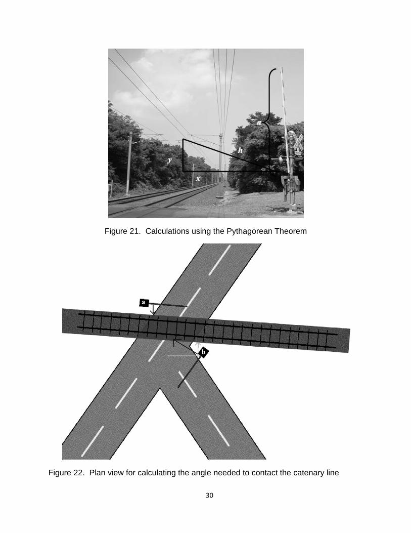
Figure 21. Calculations using the Pythagorean Theorem
Figure 22. Plan view for calculating the angle needed to contact the catenary line
1. 30
Fault Tree Analysis
In this section, a fault tree analysis of NJ Transit’s electrified grade crossings is presented and discussed. The fault tree has been developed based on NJ Transits previous known incident data and observations from site visits. This chapter contains three sections: fault tree, injury or death, and damage to grade crossing equipment. The first section discusses the two fault trees that were developed. The remaining sections discuss the impact the fault trees have on determining how a gate arm can come in contact with or entangled in static, signal power and catenary wires.
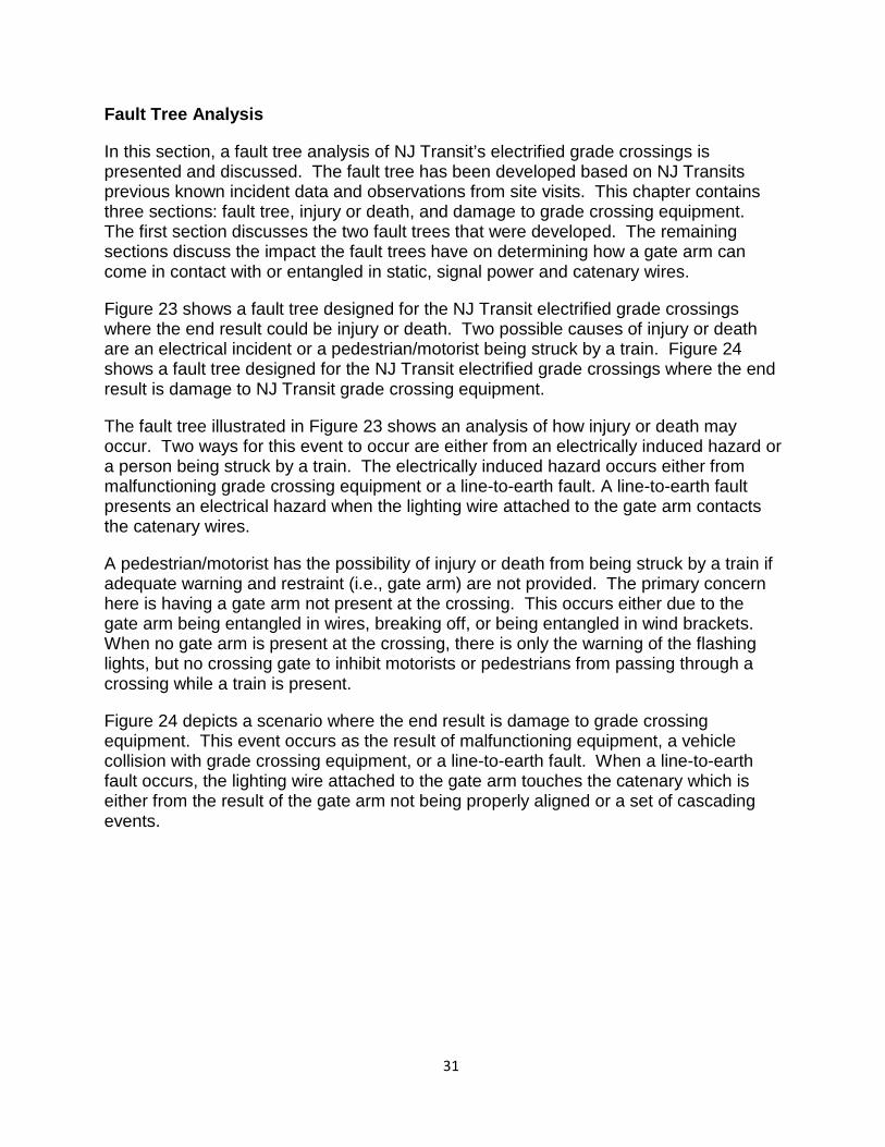
Figure 23 shows a fault tree designed for the NJ Transit electrified grade crossings where the end result could be injury or death. Two possible causes of injury or death are an electrical incident or a pedestrian/motorist being struck by a train. Figure 24 shows a fault tree designed for the NJ Transit electrified grade crossings where the end result is damage to NJ Transit grade crossing equipment.
The fault tree illustrated in Figure 23 shows an analysis of how injury or death may occur. Two ways for this event to occur are either from an electrically induced hazard or a person being struck by a train. The electrically induced hazard occurs either from malfunctioning grade crossing equipment or a line-to-earth fault. A line-to-earth fault presents an electrical hazard when the lighting wire attached to the gate arm contacts the catenary wires.
A pedestrian/motorist has the possibility of injury or death from being struck by a train if adequate warning and restraint (i.e., gate arm) are not provided. The primary concern here is having a gate arm not present at the crossing. This occurs either due to the gate arm being entangled in wires, breaking off, or being entangled in wind brackets. When no gate arm is present at the crossing, there is only the warning of the flashing lights, but no crossing gate to inhibit motorists or pedestrians from passing through a crossing while a train is present.
Figure 24 depicts a scenario where the end result is damage to grade crossing equipment. This event occurs as the result of malfunctioning equipment, a vehicle collision with grade crossing equipment, or a line-to-earth fault. When a line-to-earth fault occurs, the lighting wire attached to the gate arm touches the catenary which is either from the result of the gate arm not being properly aligned or a set of cascading events.
1. 31
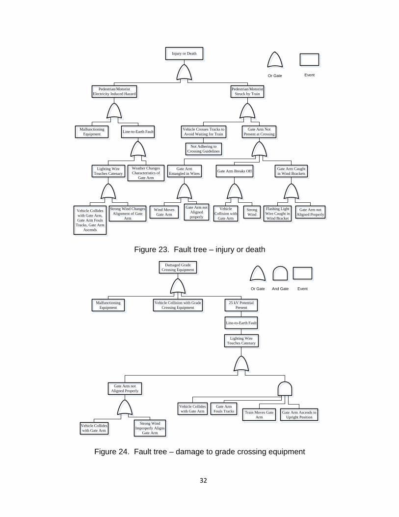
Figure 23. Fault tree – injury or death
Damaged Grade Crossing EquipmentDamaged Grade
Crossing Equipment
Malfunctioning Equipment
Malfunctioning Equipment
25 kV Potential Present
25 kV Potential Present
Lighting Wire Touches CatenaryLighting Wire
Touches Catenary
Gate Arm not Aligned ProperlyGate Arm not
Aligned Properly
Vehicle Collides with Gate Arm
Vehicle Collides with Gate Arm
Strong Wind Improperly Aligns
Gate Arm
Strong Wind Improperly Aligns
Gate Arm
Line-to-Earth FaultLine-to-Earth Fault
Vehicle Collides with Gate Arm
Vehicle Collides with Gate Arm
Gate Arm Fouls TracksGate Arm
Fouls TracksTrain Moves Gate
ArmTrain Moves Gate
ArmGate Arm Ascends to
Upright PositionGate Arm Ascends to
Upright Position
Or Gate And Gate Event
Vehicle Collision with Grade Crossing Equipment
Vehicle Collision with Grade Crossing Equipment
Figure 24. Fault tree – damage to grade crossing equipment
Injury or DeathInjury or Death
Pedestrian/Motorist Electricity Induced Hazard
Pedestrian/Motorist Electricity Induced Hazard
Pedestrian/Motorist Struck by Train
Pedestrian/Motorist Struck by Train
Vehicle Crosses Tracks to Avoid Waiting for Train
Vehicle Crosses Tracks to Avoid Waiting for Train
Gate Arm Not Present at Crossing
Gate Arm Not Present at Crossing
Gate Arm Entangled in Wires
Gate Arm Entangled in Wires
Gate Arm Caught in Wind Brackets
Gate Arm Caught in Wind Brackets
Not Adhering to Crossing GuidelinesNot Adhering to
Crossing Guidelines
Gate Arm Breaks OffGate Arm Breaks Off
Wind Moves Gate Arm
Wind Moves Gate Arm
Gate Arm not Aligned properly
Gate Arm not Aligned properly
Vehicle Collision with
Gate Arm
Vehicle Collision with
Gate Arm
Strong Wind
Strong Wind
Flashing Light Wire Caught in Wind Bracket
Flashing Light Wire Caught in Wind Bracket
Gate Arm not Aligned ProperlyGate Arm not
Aligned Properly
Malfunctioning Equipment
Malfunctioning Equipment Line-to-Earth FaultLine-to-Earth Fault
Lighting Wire Touches CatenaryLighting Wire
Touches CatenaryWeather Changes Characteristics of
Gate Arm
Weather Changes Characteristics of
Gate Arm
Vehicle Collides with Gate Arm, Gate Arm Fouls
Tracks, Gate Arm Ascends
Vehicle Collides with Gate Arm, Gate Arm Fouls
Tracks, Gate Arm Ascends
Strong Wind Changes Alignment of Gate
Arm
Strong Wind Changes Alignment of Gate
Arm
Or Gate Event
1. 32
Fault Tree Analysis – Injury or Death
As shown earlier from the database provided by NJ Transit regarding previous known incidents, one incident in particular that has been observed is a crossing gate arm caught “in wires.” A gate arm caught “in wires,” when traversing through Figure 23, essentially takes the gate arm out of service which leads to the same result as a gate arm being caught in wind brackets. The key point gained from this is that the real risk of a gate arm being stuck in static wires, signal power wires, or wind brackets is taking the gate arm out of service which may lead to risk of a crossing-related incident.
As illustrated in Figure 24 an electrically induced hazard is also an event which may lead to the potential for injury or death. Within the database provided by NJ Transit regarding previous known incidents, a major electrically induced hazard seen among NJ Transit’s grade crossings is a line-to-earth fault. This event leads to the most dangerous/catastrophic scenario, however since the shear pins have been welded, it currently requires a compound string of events to occur. First a vehicle needs to collide with the crossing gate arm. This will occur when a crossing gate arm is descending and a vehicle unsuccessfully tries to avoid the gate arm. Once the gate arm has been struck, it could now be fouling the crossing tracks while the train passes through. Once the gate arm begins to return to its upright position, it then touches the catenary wires causing a line-to-earth fault. As a result line-to-earth faults rarely occur. However, due to the significant consequences of this event, it still must be considered even though it may rarely happen. The risk here is not only taking the gate arm out of service, but presenting a danger to pedestrians, motorists, and NJ Transit technicians with the presence of an electrical potential of approximately 25 kV.
Fault Tree Analysis – Damage to Grade Crossing Equipment
Figure 24 illustrates a fault tree where the end result is damage to grade crossing equipment. This is a result that may be caused by malfunctioning equipment, a vehicle collision, or a line-to-earth fault. Figure 24 illustrates that a compound event must occur for a gate arm to contact the catenary wires. The series of events matches those stated in the previous subsection. The type of damage incurred from malfunctioning equipment or a vehicle collision with grade crossing equipment is minimal compared to the damaged incurred from a line-to-earth fault.
The damage resulting from a line-to-earth fault could include, but is not limited to, a damaged gate arm, damaged flashing light units for the entire crossing, damaged relays and resistors, as well as the possibility of a fire damaging hardware within the housing cabinet for the equipment of the NJ Transit grade crossing site. The risk with this type of event is having the potential to damage grade crossing equipment. This will cost money and affect service.
Data Analysis and Possibilities of Incidents
This section presents an analysis of the possibility of crossing gate arms contacting static, signal power and catenary lines. An assessment is presented regarding how many grade crossings having a gate arm exhibiting characteristics for contacting a wire,
1. 33
and identifying these crossings and gate arms. This assessment was derived using a worst case scenario.
Signal Power and Static Line Analysis
Site visits were made to each crossing. During each visit, data were collected to aid in determining if a crossing gate arm exhibited characteristics that would allow for the possibility of contacting lines. The potential for a gate arm to contact the signal power or static lines can be evaluated based on data collected during the site visits.
Improvements NJ Transit made include insulating the signal power wires, moving the signal power wires or static wires, shortening the gate arms and lowering the flashing light units attached to the gate arm. Lowering the flashing light units eliminate the possibility for entanglement. From grade crossing investigations it was observed that some sites where previous known incidents had occurred have been corrected and no longer have the possibility for contact with any wires. Table 7 shows which crossings currently have the possibilty for contacting the signal power or static wires. The crossing gate arms are sorted according to horizontal distances in bins of: 0’ to 2’, 2’ to 5’, and greater than 5’.
Comparing the crossings identified in Table 7 with the table of previous known incidents (Appendix A) with signal power and static lines suggests that some sites have been cleared due to the modifications that NJ Transit has implemented.
1. 34
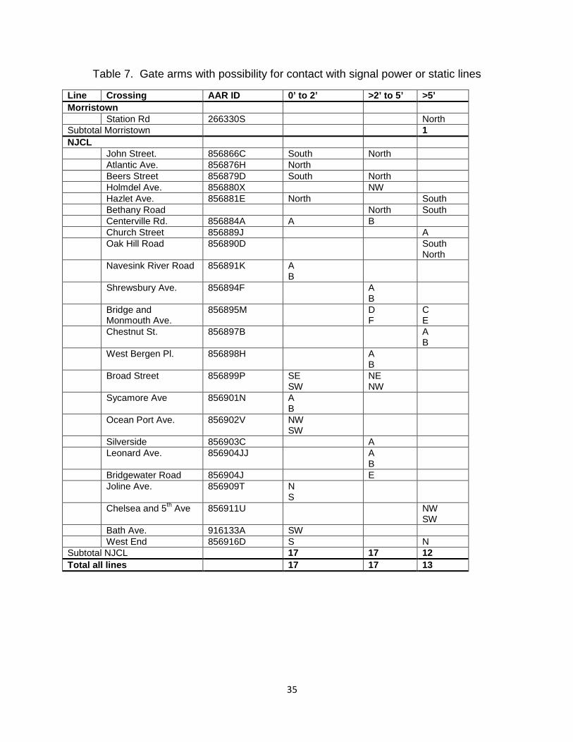
Table 7. Gate arms with possibility for contact with signal power or static lines
Line Crossing AAR ID 0’ to 2’ >2’ to 5’ >5’ Morristown Station Rd 266330S North Subtotal Morristown 1 NJCL John Street. 856866C South North Atlantic Ave. 856876H North Beers Street 856879D South North Holmdel Ave. 856880X NW Hazlet Ave. 856881E North South Bethany Road North South Centerville Rd. 856884A A B Church Street 856889J A Oak Hill Road 856890D South
North Navesink River Road 856891K A
B
Shrewsbury Ave. 856894F A B
Bridge and Monmouth Ave.
856895M D F
C E
Chestnut St. 856897B A B
West Bergen Pl. 856898H A B
Broad Street 856899P SE SW
NE NW
Sycamore Ave 856901N A B
Ocean Port Ave. 856902V NW SW
Silverside 856903C A Leonard Ave. 856904JJ A
B
Bridgewater Road 856904J E Joline Ave. 856909T N
S
Chelsea and 5th Ave 856911U NW SW
Bath Ave. 916133A SW West End 856916D S N Subtotal NJCL 17 17 12 Total all lines 17 17 13
1. 35
Gate Arms with Possibility of Contact with Catenary Line
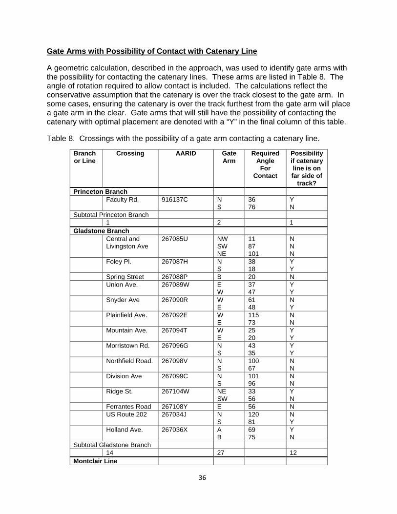
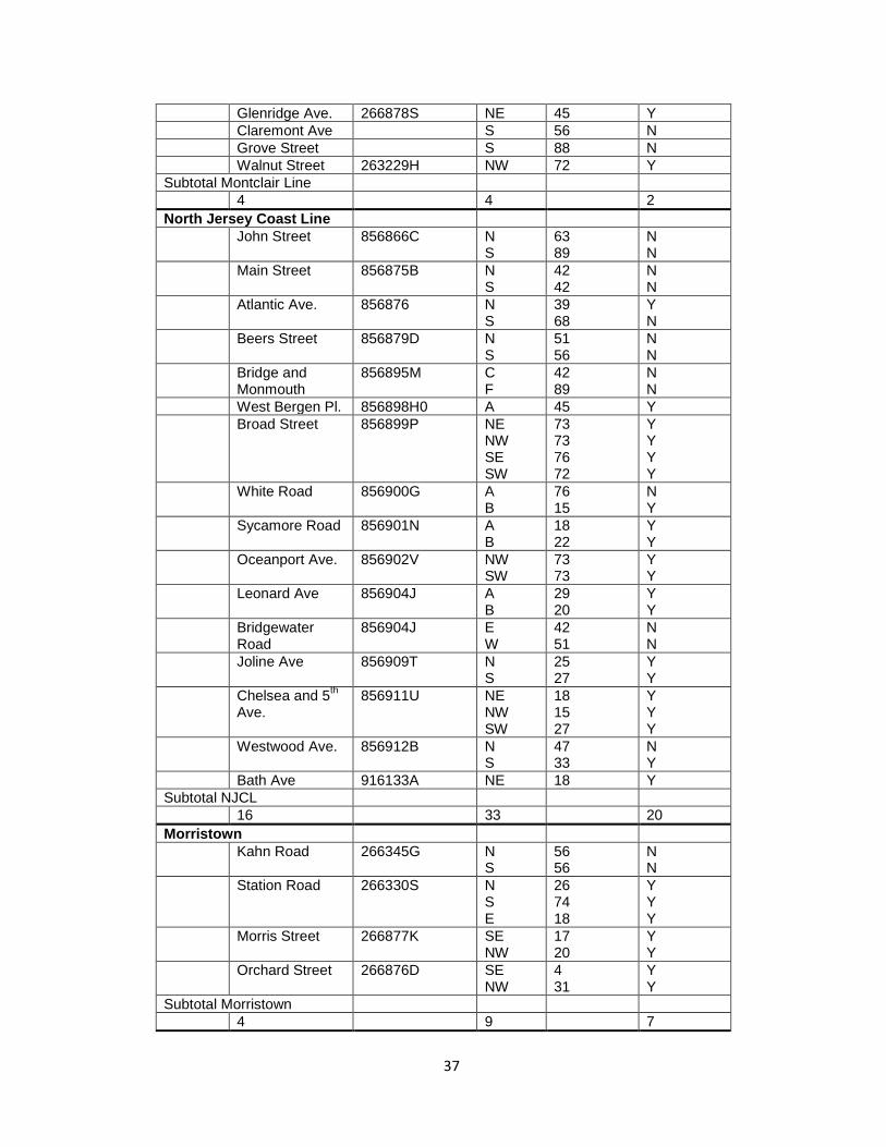
A geometric calculation, described in the approach, was used to identify gate arms with the possibility for contacting the catenary lines. These arms are listed in Table 8. The angle of rotation required to allow contact is included. The calculations reflect the conservative assumption that the catenary is over the track closest to the gate arm. In some cases, ensuring the catenary is over the track furthest from the gate arm will place a gate arm in the clear. Gate arms that will still have the possibility of contacting the catenary with optimal placement are denoted with a “Y” in the final column of this table.
Table 8. Crossings with the possibility of a gate arm contacting a catenary line.
Branch or Line
Crossing AARID Gate Arm
Required Angle
For Contact
Possibility if catenary line is on far side of
track? Princeton Branch Faculty Rd. 916137C N
S 36 76
Y N
Subtotal Princeton Branch 1 2 1 Gladstone Branch Central and
Livingston Ave 267085U NW
SW NE
11 87 101
N N N
Foley Pl. 267087H N S
38 18
Y Y
Spring Street 267088P B 20 N Union Ave. 267089W E
W 37 47
Y Y
Snyder Ave 267090R W E
61 48
N Y
Plainfield Ave. 267092E W E
115 73
N N
Mountain Ave. 267094T W E
25 20
Y Y
Morristown Rd. 267096G N S
43 35
Y Y
Northfield Road. 267098V N S
100 67
N N
Division Ave 267099C N S
101 96
N N
Ridge St. 267104W NE SW
33 56
Y N
Ferrantes Road 267108Y E 56 N US Route 202 267034J N
S 120 81
N Y
Holland Ave. 267036X A B
69 75
Y N
Subtotal Gladstone Branch 14 27 12 Montclair Line
1. 36
Glenridge Ave. 266878S NE 45 Y Claremont Ave S 56 N Grove Street S 88 N Walnut Street 263229H NW 72 Y Subtotal Montclair Line 4 4 2 North Jersey Coast Line John Street 856866C N
S 63 89
N N
Main Street 856875B N S
42 42
N N
Atlantic Ave. 856876 N S
39 68
Y N
Beers Street 856879D N S
51 56
N N
Bridge and Monmouth
856895M C F
42 89
N N
West Bergen Pl. 856898H0 A 45 Y Broad Street 856899P NE
NW SE SW
73 73 76 72
Y Y Y Y
White Road 856900G A B
76 15
N Y
Sycamore Road 856901N A B
18 22
Y Y
Oceanport Ave. 856902V NW SW
73 73
Y Y
Leonard Ave 856904J A B
29 20
Y Y
Bridgewater Road
856904J E W
42 51
N N
Joline Ave 856909T N S
25 27
Y Y
Chelsea and 5th Ave.
856911U NE NW SW
18 15 27
Y Y Y
Westwood Ave. 856912B N S
47 33
N Y
Bath Ave 916133A NE 18 Y Subtotal NJCL 16 33 20 Morristown Kahn Road 266345G N
S 56 56
N N
Station Road 266330S N S E
26 74 18
Y Y Y
Morris Street 266877K SE NW
17 20
Y Y
Orchard Street 266876D SE NW
4 31
Y Y
Subtotal Morristown 4 9 7
1. 37
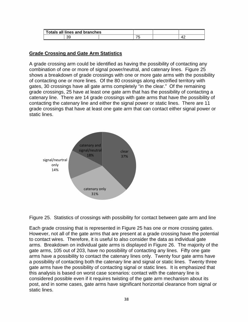
Totals all lines and branches 39 75 42
Grade Crossing and Gate Arm Statistics
A grade crossing arm could be identified as having the possibility of contacting any combination of one or more of signal power/neutral, and catenary lines. Figure 25 shows a breakdown of grade crossings with one or more gate arms with the possibility of contacting one or more lines. Of the 80 crossings along electrified territory with gates, 30 crossings have all gate arms completely “in the clear.” Of the remaining grade crossings, 25 have at least one gate arm that has the possibility of contacting a catenary line. There are 14 grade crossings with gate arms that have the possibility of contacting the catenary line and either the signal power or static lines. There are 11 grade crossings that have at least one gate arm that can contact either signal power or static lines.
Figure 25. Statistics of crossings with possibility for contact between gate arm and line
Each grade crossing that is represented in Figure 25 has one or more crossing gates. However, not all of the gate arms that are present at a grade crossing have the potential to contact wires. Therefore, it is useful to also consider the data as individual gate arms. Breakdown on individual gate arms is displayed in Figure 26. The majority of the gate arms, 105 out of 203, have no possibility of contacting any lines. Fifty one gate arms have a possibility to contact the catenary lines only. Twenty four gate arms have a possibility of contacting both the catenary line and signal or static lines. Twenty three gate arms have the possibility of contacting signal or static lines. It is emphasized that this analysis is based on worst case scenarios: contact with the catenary line is considered possible even if it requires twisting of the gate arm mechanism about its post, and in some cases, gate arms have significant horizontal clearance from signal or static lines.
clear 37%
catenary only 31%
signal/neurtral only 14%
catenary and signal/neutral
18%
1. 38
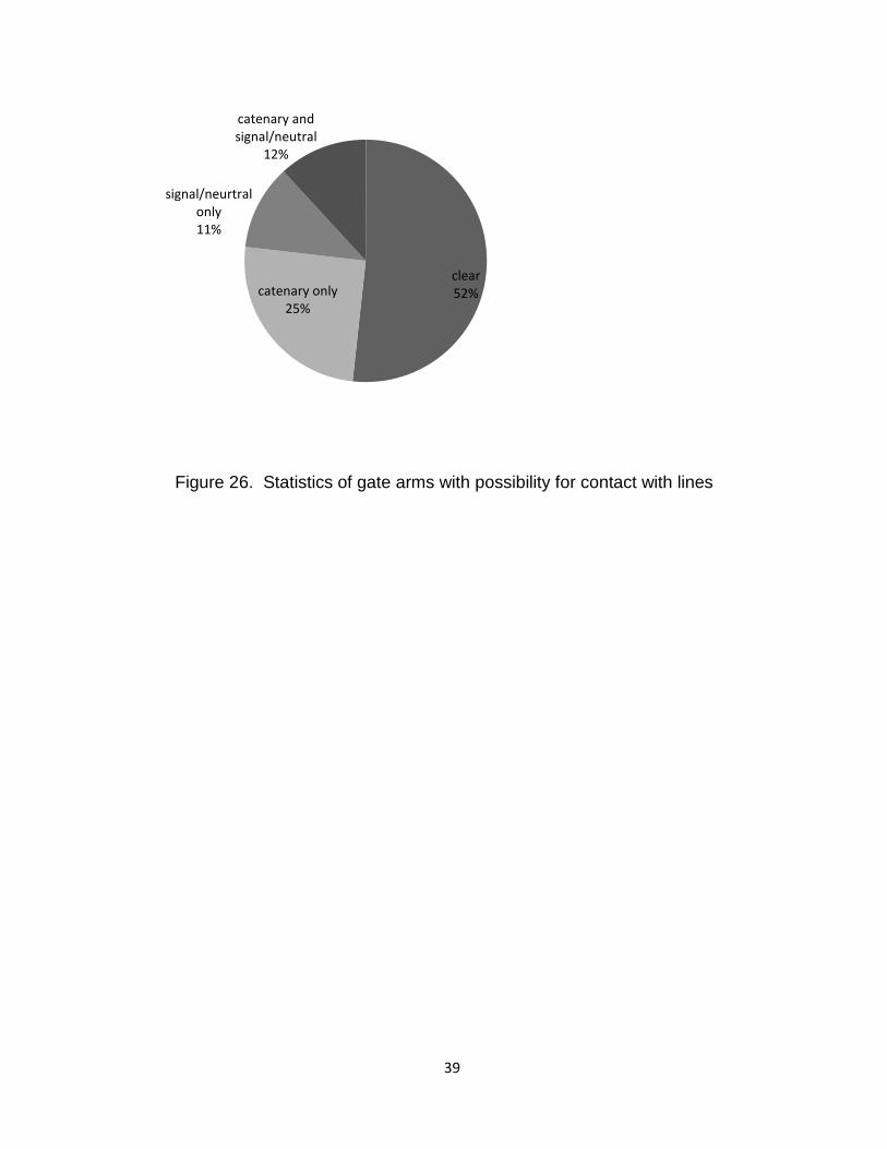
Figure 26. Statistics of gate arms with possibility for contact with lines
clear 52% catenary only
25%
signal/neurtral only 11%
catenary and signal/neutral
12%
1. 39
CONCLUSIONS AND RECOMMENDATIONS
This section presents conclusions and recommendations drawn from the project. Conclusions and recommendations are divided into three groups. First are recommendations related to preventing contact with the catenary lines. Next are recommendations related to preventing entanglement with signal power and static lines. Finally are recommendations related to future design of grade crossings in electrified territory.
Preventing Contact with Catenary Lines
NJ Transit has had significant success in reducing the rate of incidents involving gate arms contacting catenary lines. This is due to corrections NJ Transit implemented on certain grade crossings, such as shortening gate arms where possible, moving flashing lights, and welding shear pins. Despite these efforts, NJ Transit has not completely removed the possibility of future contacts with catenary lines. This is due to the potential for motorists striking gate arms with vehicles, resulting in the gate arm being rotated toward the catenary line. While this is an unlikely event, it remains a possibility.
Sites with Potential to Contact Catenary Lines
Sites with the possibility of having a gate arm contact a catenary line are listed in table 8. There are a total of 21 crossings with 32 gate arms with this possibility. Although all 32 gate arms could possibly make contact with the catenary lines under certain conditions, it is presumed that gate arms requiring smaller angles of rotation and with higher traffic crossings are at the highest risk.
Recommendations for Sites with the Potential of Contacting Catenary Lines
Even though an un-modified gate saver has been shown to be less than 100% effective, it still offers advantages over the current situation. While a gate saver might not always return the gate to position before the gate is raised, it will return the gate to position eventually. This is in contrast to a normal gate which, when twisted by an automobile, will remain in the way of the track. However, the gate saver can be improved upon. Therefore, the main recommendation is to develop and implement an amended gate saver which will not allow the gate arm to return to its upright position until the gate arm has fully retracted. As the failsafe (zero power) position of the driving mechanism results in the gate being lowered, it is reasonably straightforward to modify the gate mechanism and gate saver mechanisms to accomplish this. A basic configuration for this circuit involves a simple short/open circuit. When the gate arm is struck by a car and swings forward, the circuit opens. The open circuit cuts power to the gate raising mechanism, which precludes the gate arm from being raised. Only when the gate arm returns to its original position reconnecting the circuit will the gate arm be able to return to its upright position. As this modification will involve modifications to the gate arm mechanism, it is recommended that New Jersey Transit work with the vendors to implement this design. Schematic illustrations of concepts for circuits are shown in the Implementation and Training section.
1. 40
The second recommendation is to place extra emphasis for any Operation Lifesaver activities on crossing gates listed in Table 8. Presumably, any actions that will reduce traffic fatalities will also reduce the number of times that a gate in the down position is struck by a vehicle.
Several concepts were considered, but rejected for various reasons. The use of fiber optic lighting to eliminate copper wires along the gate arms was given serious consideration, but ultimately rejected based on Doble testing. Doble testing of gate arms clearly demonstrated that a wet fiberglass gate arm by itself is sufficient to allow a line-to-earth fault. Therefore, it is impossible to prevent a line-to-earth fault when a gate arm comes in contact with a catenary line under rainy conditions. This also eliminated various schemes to insulate the copper wires. Pop up gates, similar to those used for security checkpoints, were considered. While these will eliminate the possibility of a gate arm contacting a wire, they will introduce other issues. The most serious of these issues is the potential for a vehicle to be trapped on the tracks. This added risk is much more significant than that posed by line-to-earth faults, based on historical incident rates compared to traffic fatalities. Finally, various break-away schemes were considered. However, any modification to the gate arm that would allow it to break off leads to fatigue issues similar to before the shear pins were welded, and will increase the number of times that the gate arms are not in service.
Preventing Entanglement with Static and Signal Power Lines
In this subsection, sites that have the possibility of contacting signal power and static lines are identified, and recommendations are made to resolve these sites. A listing of these sites is given in Appendix D.
Sites with the Possibility of Contacting Static and Signal Power Lines
Table 9 is a list of sites that are considered to have a high potential for contacting static and signal wires. These gate arms have a clearance of two feet or less between the gate arm and the line in question. Table 10 is a list of sites that have lower potential for contacting static and signal wires.
1. 41
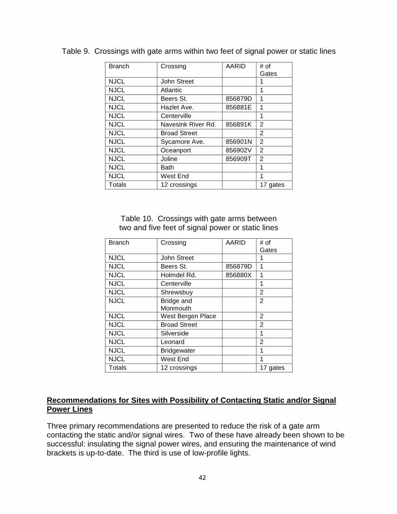
Table 9. Crossings with gate arms within two feet of signal power or static lines
Branch Crossing AARID # of Gates
NJCL John Street 1 NJCL Atlantic 1 NJCL Beers St. 856879D 1 NJCL Hazlet Ave. 856881E 1 NJCL Centerville 1 NJCL Navesink River Rd. 856891K 2 NJCL Broad Street 2 NJCL Sycamore Ave. 856901N 2 NJCL Oceanport 856902V 2 NJCL Joline 856909T 2 NJCL Bath 1 NJCL West End 1 Totals 12 crossings 17 gates
Table 10. Crossings with gate arms between two and five feet of signal power or static lines
Branch Crossing AARID # of Gates
NJCL John Street 1 NJCL Beers St. 856879D 1 NJCL Holmdel Rd. 856880X 1 NJCL Centerville 1 NJCL Shrewsbuy 2 NJCL Bridge and
Monmouth 2
NJCL West Bergen Place 2 NJCL Broad Street 2 NJCL Silverside 1 NJCL Leonard 2 NJCL Bridgewater 1 NJCL West End 1 Totals 12 crossings 17 gates
Recommendations for Sites with Possibility of Contacting Static and/or Signal Power Lines
Three primary recommendations are presented to reduce the risk of a gate arm contacting the static and/or signal wires. Two of these have already been shown to be successful: insulating the signal power wires, and ensuring the maintenance of wind brackets is up-to-date. The third is use of low-profile lights.
1. 42
Using the tables above, the use of insulation on the wires of sites with risk of contacting static and/or signal wires can help reduce the possibility of having an incident with gate arms becoming entangled with static and/or signal wires. This will prevent the gate arm from being entangled with the wires, which in turn allows the gate arm to operate properly at the crossing.
Another recommendation to reduce the risk of contact with static and/or signal wires is the use of low profile lights on the gate arm. With low profile lights, even though the gate arm touches the wires, it will not have a means to become entangled with the wires. This will also allow the gate arm to function properly at the crossing.
Lastly, the recommendation of having routine maintenance of wind brackets will help reduce the risk of contacting static and/or signal wires. This will help prevent the gate arm from becoming entangled with the wind bracket. Also, this will help to keep the gate arm properly aligned with the wind bracket. Through proper maintenance the gate arm will have little opportunity of returning incorrectly to its upright position and contacting static and/or signal wires.
Where possible, raising signal power or static lines above the height of the gate arms should be considered. However, the cost of this action will be prohibitive, unless the section of track is undergoing work that requires the lines or support structures to undergo changes for other reasons.
Recommendations for Future Grade Crossing Design
Additional grade crossings, or extension of electrified territory might lead to future issues. To reduce the risk of contacting catenary wires designers must ensure that distances between the gate arm and the catenary wires meet the minimum requirements discussed earlier. In these cases, effort should be made to place the catenary line at the greatest height allowed, and toward the inside of the track. The gate arm mechanism should be placed as far from the track as possible, given the available right of way. Where these efforts do not eliminate the possibility of contact, the recommendations should be followed for existing gates with the possibility of contact with the catenary line.
With respect to reducing gate contact with static and signal wires, signal power lines and static lines should be placed as high as the support structure allows, and toward the center of the tracks.
1. 43
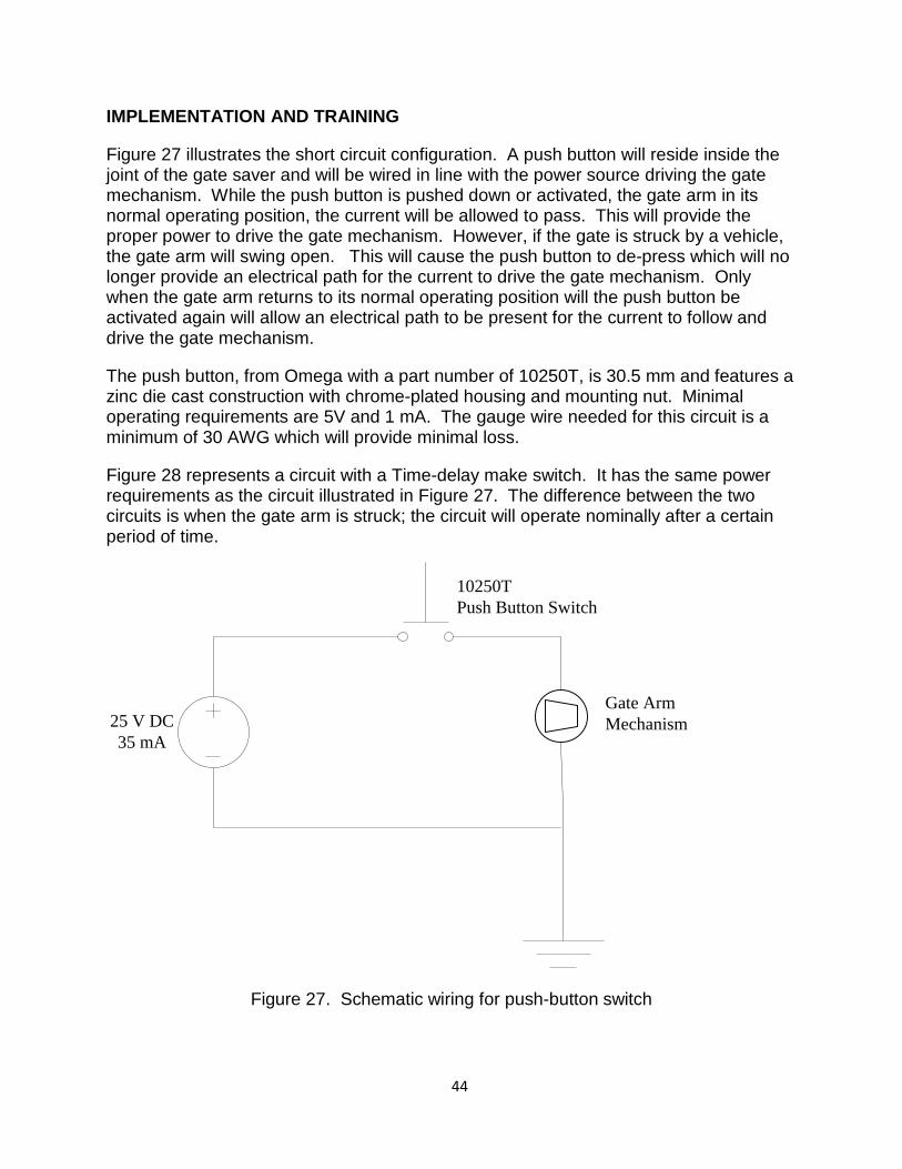
IMPLEMENTATION AND TRAINING
Figure 27 illustrates the short circuit configuration. A push button will reside inside the joint of the gate saver and will be wired in line with the power source driving the gate mechanism. While the push button is pushed down or activated, the gate arm in its normal operating position, the current will be allowed to pass. This will provide the proper power to drive the gate mechanism. However, if the gate is struck by a vehicle, the gate arm will swing open. This will cause the push button to de-press which will no longer provide an electrical path for the current to drive the gate mechanism. Only when the gate arm returns to its normal operating position will the push button be activated again will allow an electrical path to be present for the current to follow and drive the gate mechanism.
The push button, from Omega with a part number of 10250T, is 30.5 mm and features a zinc die cast construction with chrome-plated housing and mounting nut. Minimal operating requirements are 5V and 1 mA. The gauge wire needed for this circuit is a minimum of 30 AWG which will provide minimal loss.
Figure 28 represents a circuit with a Time-delay make switch. It has the same power requirements as the circuit illustrated in Figure 27. The difference between the two circuits is when the gate arm is struck; the circuit will operate nominally after a certain period of time.
Figure 27. Schematic wiring for push-button switch
25 V DC35 mA
10250T Push Button Switch
Gate Arm Mechanism
1. 44
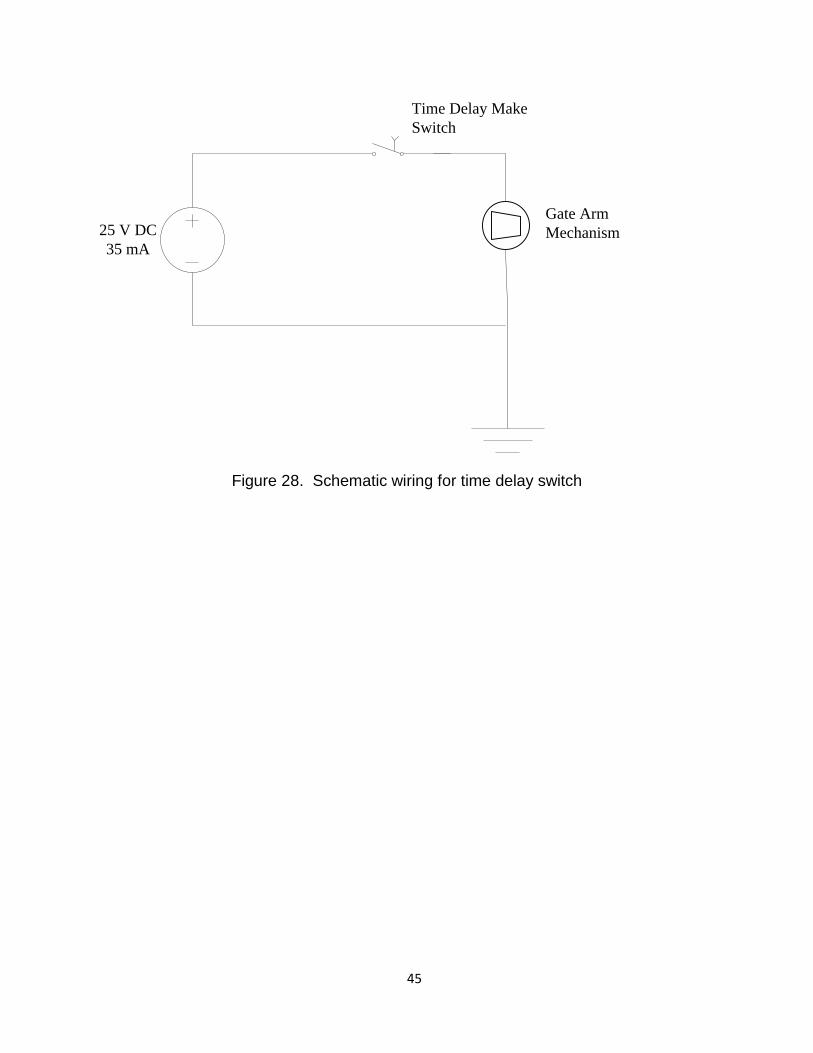
Figure 28. Schematic wiring for time delay switch
25 V DC35 mA
Time Delay Make Switch
Gate Arm Mechanism
1. 45
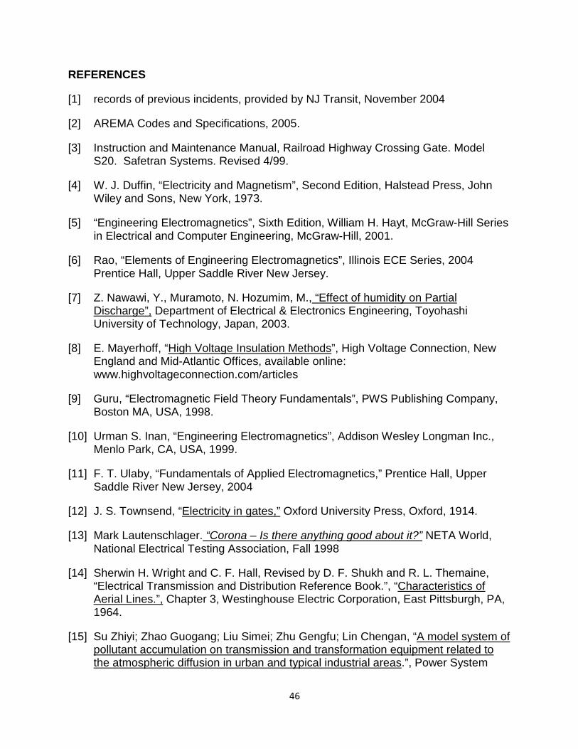
REFERENCES
[1] records of previous incidents, provided by NJ Transit, November 2004
[2] AREMA Codes and Specifications, 2005.
[3] Instruction and Maintenance Manual, Railroad Highway Crossing Gate. Model S20. Safetran Systems. Revised 4/99.
[4] W. J. Duffin, “Electricity and Magnetism”, Second Edition, Halstead Press, John Wiley and Sons, New York, 1973.
[5] “Engineering Electromagnetics”, Sixth Edition, William H. Hayt, McGraw-Hill Series in Electrical and Computer Engineering, McGraw-Hill, 2001.
[6] Rao, “Elements of Engineering Electromagnetics”, Illinois ECE Series, 2004 Prentice Hall, Upper Saddle River New Jersey.
[7] Z. Nawawi, Y., Muramoto, N. Hozumim, M., “Effect of humidity on Partial Discharge”, Department of Electrical & Electronics Engineering, Toyohashi University of Technology, Japan, 2003.
[8] E. Mayerhoff, “High Voltage Insulation Methods”, High Voltage Connection, New England and Mid-Atlantic Offices, available online: www.highvoltageconnection.com/articles
[9] Guru, “Electromagnetic Field Theory Fundamentals”, PWS Publishing Company, Boston MA, USA, 1998.
[10] Urman S. Inan, “Engineering Electromagnetics”, Addison Wesley Longman Inc., Menlo Park, CA, USA, 1999.
[11] F. T. Ulaby, “Fundamentals of Applied Electromagnetics,” Prentice Hall, Upper Saddle River New Jersey, 2004
[12] J. S. Townsend, “Electricity in gates,” Oxford University Press, Oxford, 1914.
[13] Mark Lautenschlager. “Corona – Is there anything good about it?” NETA World, National Electrical Testing Association, Fall 1998
[14] Sherwin H. Wright and C. F. Hall, Revised by D. F. Shukh and R. L. Themaine, “Electrical Transmission and Distribution Reference Book.”, “Characteristics of Aerial Lines.”, Chapter 3, Westinghouse Electric Corporation, East Pittsburgh, PA, 1964.
[15] Su Zhiyi; Zhao Guogang; Liu Simei; Zhu Gengfu; Lin Chengan, “A model system of pollutant accumulation on transmission and transformation equipment related to the atmospheric diffusion in urban and typical industrial areas.”, Power System
1. 46
Technology, 1998. Proceedings. POWERCON '98. 1998 International Conference on, Volume 1,18-21 Aug. 1998 Page(s):543 – 546.
[16] Matlab Users Manual, Matlab 6.5 Release 13, Mathworks Inc, 2002.
[17] Y. Yang, “An efficient method for computing the magnetic fields generated by transmission lines with static wires.”, Safe Eng. Services & Technol. Ltd., Montreal, Que., Canada, International Conference on Power System Technology, 2002.
[18] Doble Engineering, Three-electrode test manual, 2005.
[19] New Jersey Transit Grade Crossing Equipment Inventory, provided by NJ Transit, November, 2004.
[20] NJ Transit Grade Crossings in Electrified Territory (Excel Spreadsheet), Provided by NJ Transit, November 4, 2004.
1. 47
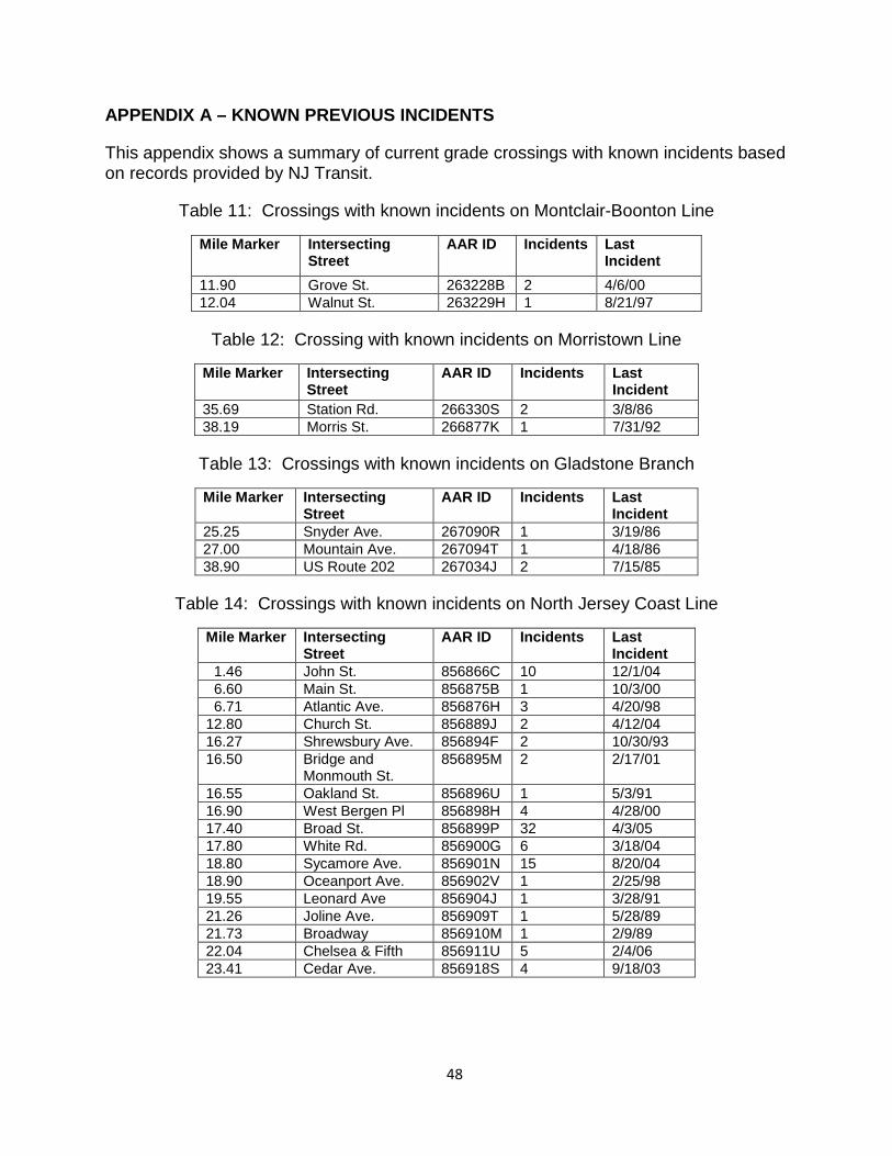
APPENDIX A – KNOWN PREVIOUS INCIDENTS
This appendix shows a summary of current grade crossings with known incidents based on records provided by NJ Transit.
Table 11: Crossings with known incidents on Montclair-Boonton Line
Mile Marker Intersecting Street
AAR ID Incidents Last Incident
11.90 Grove St. 263228B 2 4/6/00 12.04 Walnut St. 263229H 1 8/21/97
Table 12: Crossing with known incidents on Morristown Line
Mile Marker Intersecting Street
AAR ID Incidents Last Incident
35.69 Station Rd. 266330S 2 3/8/86 38.19 Morris St. 266877K 1 7/31/92
Table 13: Crossings with known incidents on Gladstone Branch
Mile Marker Intersecting Street
AAR ID Incidents Last Incident
25.25 Snyder Ave. 267090R 1 3/19/86 27.00 Mountain Ave. 267094T 1 4/18/86 38.90 US Route 202 267034J 2 7/15/85
Table 14: Crossings with known incidents on North Jersey Coast Line
Mile Marker Intersecting Street
AAR ID Incidents Last Incident
1.46 John St. 856866C 10 12/1/04 6.60 Main St. 856875B 1 10/3/00 6.71 Atlantic Ave. 856876H 3 4/20/98 12.80 Church St. 856889J 2 4/12/04 16.27 Shrewsbury Ave. 856894F 2 10/30/93 16.50 Bridge and
Monmouth St. 856895M 2 2/17/01
16.55 Oakland St. 856896U 1 5/3/91 16.90 West Bergen Pl 856898H 4 4/28/00 17.40 Broad St. 856899P 32 4/3/05 17.80 White Rd. 856900G 6 3/18/04 18.80 Sycamore Ave. 856901N 15 8/20/04 18.90 Oceanport Ave. 856902V 1 2/25/98 19.55 Leonard Ave 856904J 1 3/28/91 21.26 Joline Ave. 856909T 1 5/28/89 21.73 Broadway 856910M 1 2/9/89 22.04 Chelsea & Fifth 856911U 5 2/4/06 23.41 Cedar Ave. 856918S 4 9/18/03
1. 48
APPENDIX B. CASE STUDIES
This appendix presents three case studies of several grade crossings, Sycamore Avenue, Station Road, and Chelsea and 5th Avenue that have known incidents. Sycamore Avenue and Station Road’s grade crossing is discussed extensively and is presented with thirteen and two known incidents respectively. Lastly, the grade crossing of Chelsea and 5th Avenue’s latest incident on 2/4/2006 is presented and discussed.
Sycamore Ave.
The Sycamore Ave. crossing is part of the North Jersey Coast Line. An overhead view of the crossing is shown in Figure 29. The angle between the gate arm and the tracks is approximately 71o and can be seen that the track does not curve. There are three crossing gate arms at this crossing, one is used for a pedestrian crossing while the others are for traffic and are to the southeast and northwest of the crossing. The northwest gate has a length of 31 feet, the southeast gate is 27 feet, and the pedestrian crossing gate arm is seven feet in length. Results from database of previous known incidents given by NJ Transit that pertain to this crossing are summarized in Table 15. The data presented in the table above suggests there is a significant issue with gate arms contacting and becoming entangled in the signal power and static wires at this site. There was one recorded incident where a gate arm contacted the catenary wires, which resulted from a vehicle collision with the gate arm. The comments for the incident involving the catenary wire stated “apparently lots of damage.” Historical weather data has been included for the days when incidents occurred. The northwest and southeast bound gate arms are both identified as being involved in multiple incidents, while the pedestrian gate arm is not identified for any incidents.
1. 49
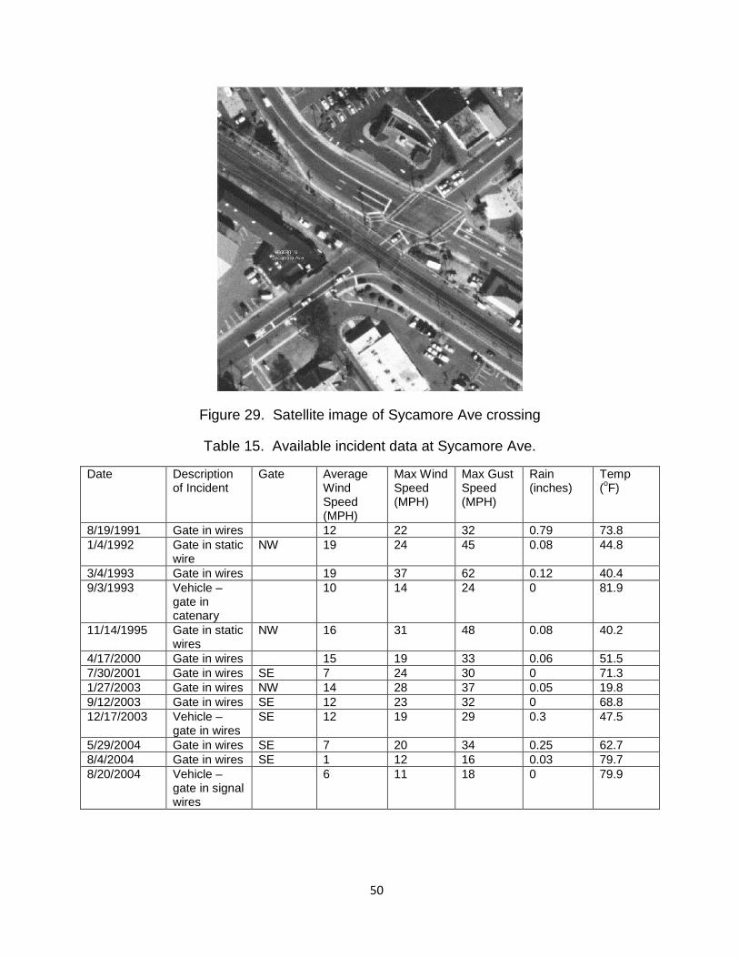
Figure 29. Satellite image of Sycamore Ave crossing
Table 15. Available incident data at Sycamore Ave.
Date Description of Incident
Gate Average Wind Speed (MPH)
Max Wind Speed (MPH)
Max Gust Speed (MPH)
Rain (inches)
Temp (oF)
8/19/1991 Gate in wires 12 22 32 0.79 73.8 1/4/1992 Gate in static
wire NW 19 24 45 0.08 44.8
3/4/1993 Gate in wires 19 37 62 0.12 40.4 9/3/1993 Vehicle –
gate in catenary
10 14 24 0 81.9
11/14/1995 Gate in static wires
NW 16 31 48 0.08 40.2
4/17/2000 Gate in wires 15 19 33 0.06 51.5 7/30/2001 Gate in wires SE 7 24 30 0 71.3 1/27/2003 Gate in wires NW 14 28 37 0.05 19.8 9/12/2003 Gate in wires SE 12 23 32 0 68.8 12/17/2003 Vehicle –
gate in wires SE 12 19 29 0.3 47.5
5/29/2004 Gate in wires SE 7 20 34 0.25 62.7 8/4/2004 Gate in wires SE 1 12 16 0.03 79.7 8/20/2004 Vehicle –
gate in signal wires
6 11 18 0 79.9
1. 50
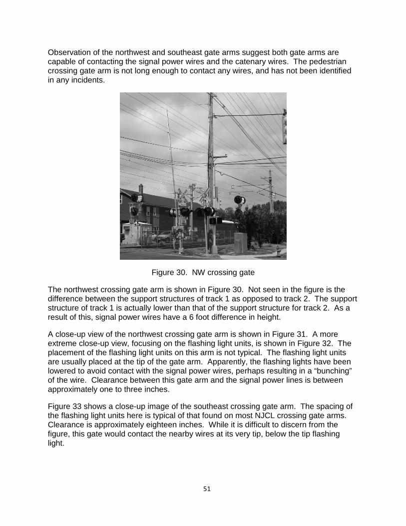
Observation of the northwest and southeast gate arms suggest both gate arms are capable of contacting the signal power wires and the catenary wires. The pedestrian crossing gate arm is not long enough to contact any wires, and has not been identified in any incidents.
Figure 30. NW crossing gate
The northwest crossing gate arm is shown in Figure 30. Not seen in the figure is the difference between the support structures of track 1 as opposed to track 2. The support structure of track 1 is actually lower than that of the support structure for track 2. As a result of this, signal power wires have a 6 foot difference in height.
A close-up view of the northwest crossing gate arm is shown in Figure 31. A more extreme close-up view, focusing on the flashing light units, is shown in Figure 32. The placement of the flashing light units on this arm is not typical. The flashing light units are usually placed at the tip of the gate arm. Apparently, the flashing lights have been lowered to avoid contact with the signal power wires, perhaps resulting in a “bunching” of the wire. Clearance between this gate arm and the signal power lines is between approximately one to three inches.
Figure 33 shows a close-up image of the southeast crossing gate arm. The spacing of the flashing light units here is typical of that found on most NJCL crossing gate arms. Clearance is approximately eighteen inches. While it is difficult to discern from the figure, this gate would contact the nearby wires at its very tip, below the tip flashing light.
1. 51
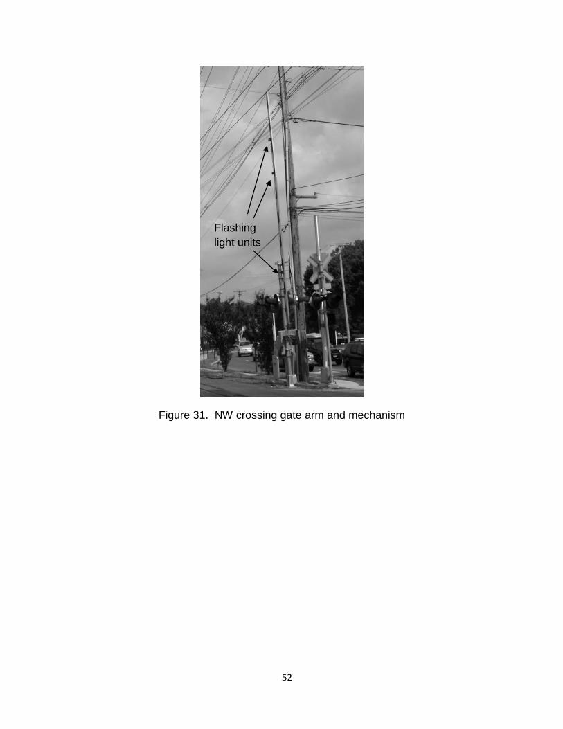
Figure 31. NW crossing gate arm and mechanism
Flashing light units
1. 52
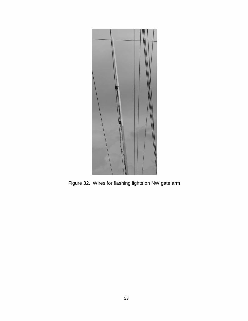
Figure 32. Wires for flashing lights on NW gate arm
1. 53
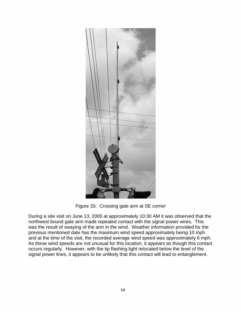
Figure 33. Crossing gate arm at SE corner
During a site visit on June 13, 2005 at approximately 10:30 AM it was observed that the northwest bound gate arm made repeated contact with the signal power wires. This was the result of swaying of the arm in the wind. Weather information provided for the previous mentioned date has the maximum wind speed approximately being 10 mph and at the time of the visit, the recorded average wind speed was approximately 6 mph. As these wind speeds are not unusual for this location, it appears as though this contact occurs regularly. However, with the tip flashing light relocated below the level of the signal power lines, it appears to be unlikely that this contact will lead to entanglement.
1. 54
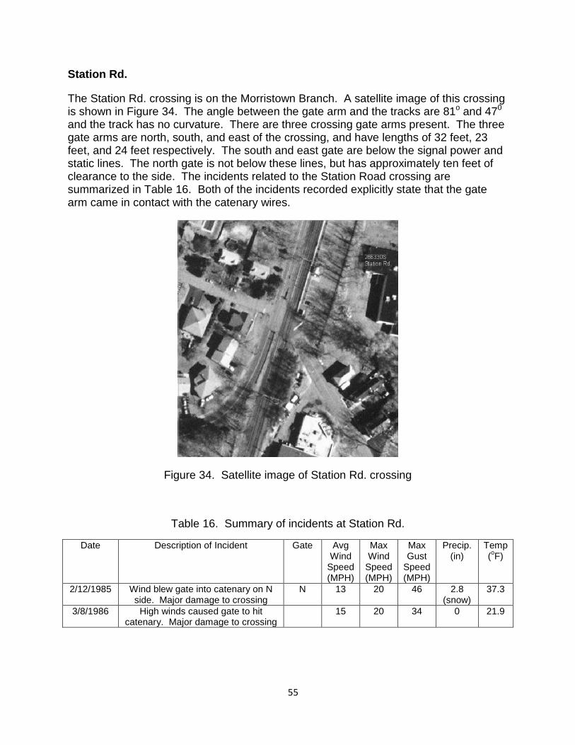
Station Rd.
The Station Rd. crossing is on the Morristown Branch. A satellite image of this crossing is shown in Figure 34. The angle between the gate arm and the tracks are 81o and 470 and the track has no curvature. There are three crossing gate arms present. The three gate arms are north, south, and east of the crossing, and have lengths of 32 feet, 23 feet, and 24 feet respectively. The south and east gate are below the signal power and static lines. The north gate is not below these lines, but has approximately ten feet of clearance to the side. The incidents related to the Station Road crossing are summarized in Table 16. Both of the incidents recorded explicitly state that the gate arm came in contact with the catenary wires.
Figure 34. Satellite image of Station Rd. crossing
Table 16. Summary of incidents at Station Rd.
Date Description of Incident Gate Avg Wind
Speed (MPH)
Max Wind
Speed (MPH)
Max Gust
Speed (MPH)
Precip. (in)
Temp (oF)
2/12/1985 Wind blew gate into catenary on N side. Major damage to crossing
N 13 20 46 2.8 (snow)
37.3
3/8/1986 High winds caused gate to hit catenary. Major damage to crossing
15 20 34 0 21.9
1. 55
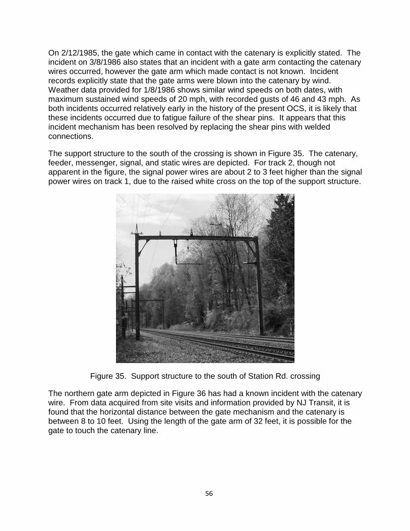
On 2/12/1985, the gate which came in contact with the catenary is explicitly stated. The incident on 3/8/1986 also states that an incident with a gate arm contacting the catenary wires occurred, however the gate arm which made contact is not known. Incident records explicitly state that the gate arms were blown into the catenary by wind. Weather data provided for 1/8/1986 shows similar wind speeds on both dates, with maximum sustained wind speeds of 20 mph, with recorded gusts of 46 and 43 mph. As both incidents occurred relatively early in the history of the present OCS, it is likely that these incidents occurred due to fatigue failure of the shear pins. It appears that this incident mechanism has been resolved by replacing the shear pins with welded connections.
The support structure to the south of the crossing is shown in Figure 35. The catenary, feeder, messenger, signal, and static wires are depicted. For track 2, though not apparent in the figure, the signal power wires are about 2 to 3 feet higher than the signal power wires on track 1, due to the raised white cross on the top of the support structure.
Figure 35. Support structure to the south of Station Rd. crossing
The northern gate arm depicted in Figure 36 has had a known incident with the catenary wire. From data acquired from site visits and information provided by NJ Transit, it is found that the horizontal distance between the gate mechanism and the catenary is between 8 to 10 feet. Using the length of the gate arm of 32 feet, it is possible for the gate to touch the catenary line.
1. 56
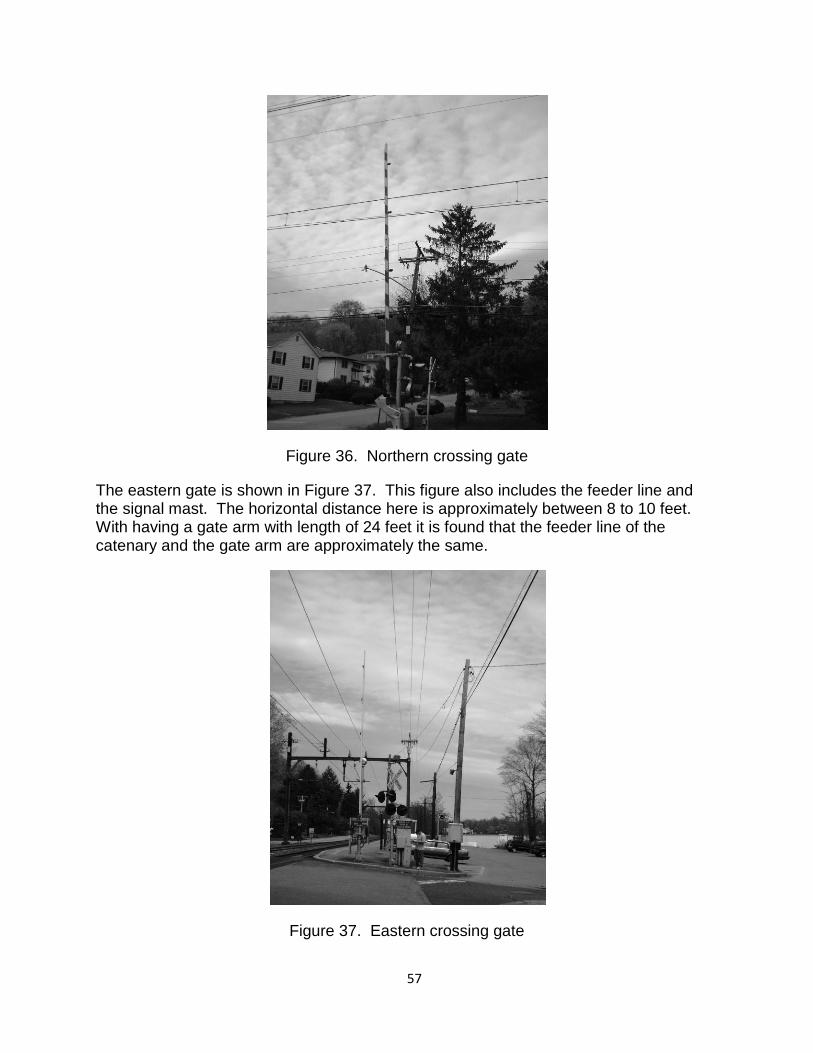
Figure 36. Northern crossing gate
The eastern gate is shown in Figure 37. This figure also includes the feeder line and the signal mast. The horizontal distance here is approximately between 8 to 10 feet. With having a gate arm with length of 24 feet it is found that the feeder line of the catenary and the gate arm are approximately the same.
Figure 37. Eastern crossing gate
1. 57
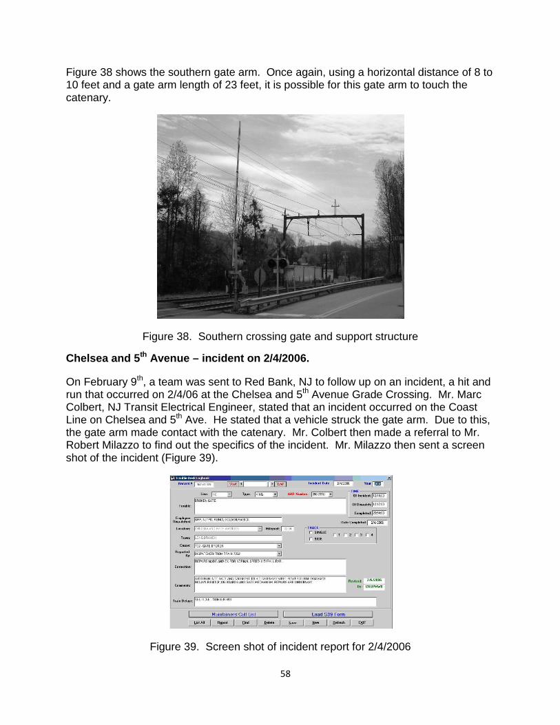
Figure 38 shows the southern gate arm. Once again, using a horizontal distance of 8 to 10 feet and a gate arm length of 23 feet, it is possible for this gate arm to touch the catenary.
Figure 38. Southern crossing gate and support structure
Chelsea and 5th Avenue – incident on 2/4/2006.
On February 9th, a team was sent to Red Bank, NJ to follow up on an incident, a hit and run that occurred on 2/4/06 at the Chelsea and 5th Avenue Grade Crossing. Mr. Marc Colbert, NJ Transit Electrical Engineer, stated that an incident occurred on the Coast Line on Chelsea and 5th Ave. He stated that a vehicle struck the gate arm. Due to this, the gate arm made contact with the catenary. Mr. Colbert then made a referral to Mr. Robert Milazzo to find out the specifics of the incident. Mr. Milazzo then sent a screen shot of the incident (Figure 39).
Figure 39. Screen shot of incident report for 2/4/2006
1. 58
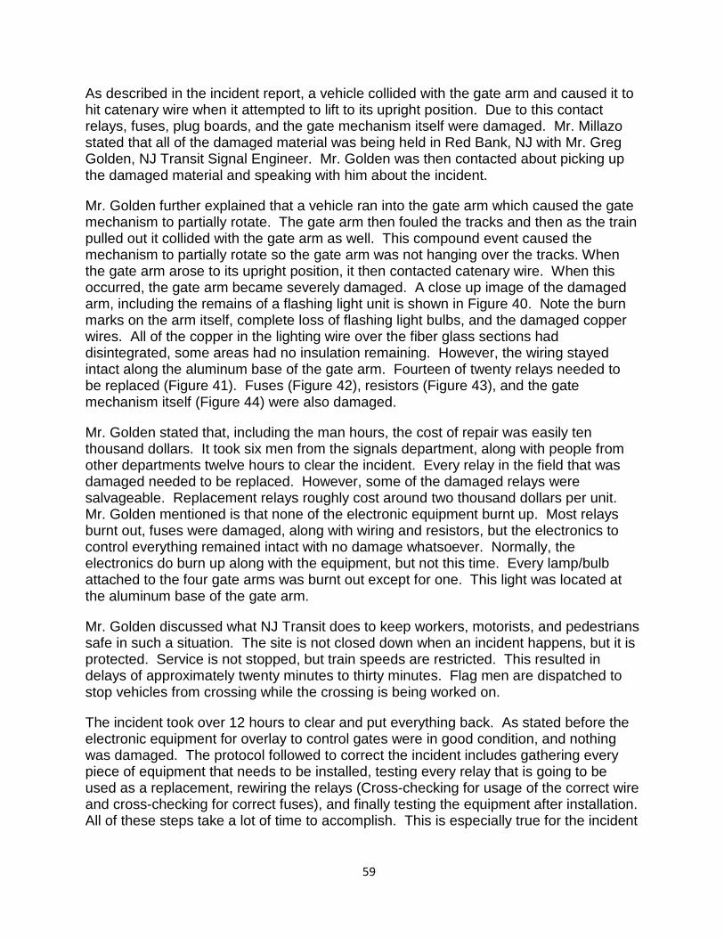
As described in the incident report, a vehicle collided with the gate arm and caused it to hit catenary wire when it attempted to lift to its upright position. Due to this contact relays, fuses, plug boards, and the gate mechanism itself were damaged. Mr. Millazo stated that all of the damaged material was being held in Red Bank, NJ with Mr. Greg Golden, NJ Transit Signal Engineer. Mr. Golden was then contacted about picking up the damaged material and speaking with him about the incident.
Mr. Golden further explained that a vehicle ran into the gate arm which caused the gate mechanism to partially rotate. The gate arm then fouled the tracks and then as the train pulled out it collided with the gate arm as well. This compound event caused the mechanism to partially rotate so the gate arm was not hanging over the tracks. When the gate arm arose to its upright position, it then contacted catenary wire. When this occurred, the gate arm became severely damaged. A close up image of the damaged arm, including the remains of a flashing light unit is shown in Figure 40. Note the burn marks on the arm itself, complete loss of flashing light bulbs, and the damaged copper wires. All of the copper in the lighting wire over the fiber glass sections had disintegrated, some areas had no insulation remaining. However, the wiring stayed intact along the aluminum base of the gate arm. Fourteen of twenty relays needed to be replaced (Figure 41). Fuses (Figure 42), resistors (Figure 43), and the gate mechanism itself (Figure 44) were also damaged.
Mr. Golden stated that, including the man hours, the cost of repair was easily ten thousand dollars. It took six men from the signals department, along with people from other departments twelve hours to clear the incident. Every relay in the field that was damaged needed to be replaced. However, some of the damaged relays were salvageable. Replacement relays roughly cost around two thousand dollars per unit. Mr. Golden mentioned is that none of the electronic equipment burnt up. Most relays burnt out, fuses were damaged, along with wiring and resistors, but the electronics to control everything remained intact with no damage whatsoever. Normally, the electronics do burn up along with the equipment, but not this time. Every lamp/bulb attached to the four gate arms was burnt out except for one. This light was located at the aluminum base of the gate arm.
Mr. Golden discussed what NJ Transit does to keep workers, motorists, and pedestrians safe in such a situation. The site is not closed down when an incident happens, but it is protected. Service is not stopped, but train speeds are restricted. This resulted in delays of approximately twenty minutes to thirty minutes. Flag men are dispatched to stop vehicles from crossing while the crossing is being worked on.
The incident took over 12 hours to clear and put everything back. As stated before the electronic equipment for overlay to control gates were in good condition, and nothing was damaged. The protocol followed to correct the incident includes gathering every piece of equipment that needs to be installed, testing every relay that is going to be used as a replacement, rewiring the relays (Cross-checking for usage of the correct wire and cross-checking for correct fuses), and finally testing the equipment after installation. All of these steps take a lot of time to accomplish. This is especially true for the incident
1. 59
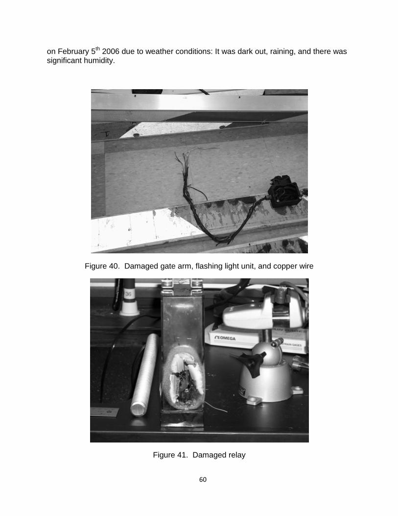
on February 5th 2006 due to weather conditions: It was dark out, raining, and there was significant humidity.
Figure 40. Damaged gate arm, flashing light unit, and copper wire
Figure 41. Damaged relay
1. 60
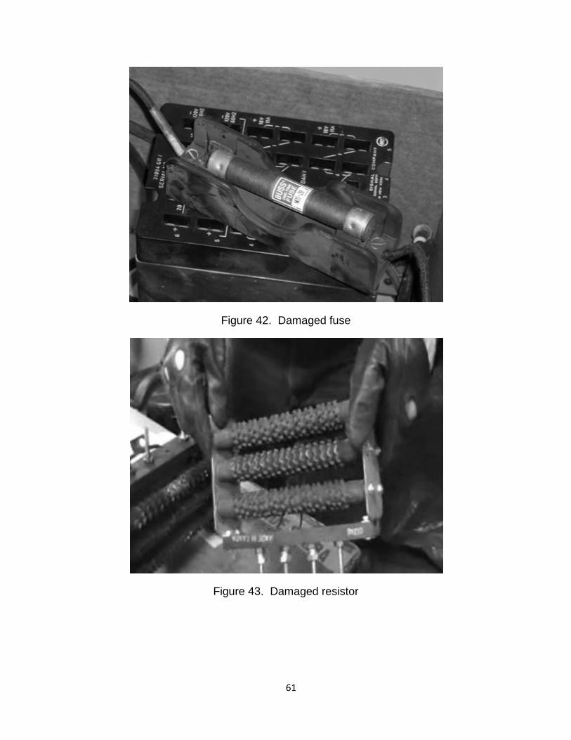
Figure 42. Damaged fuse
Figure 43. Damaged resistor
1. 61
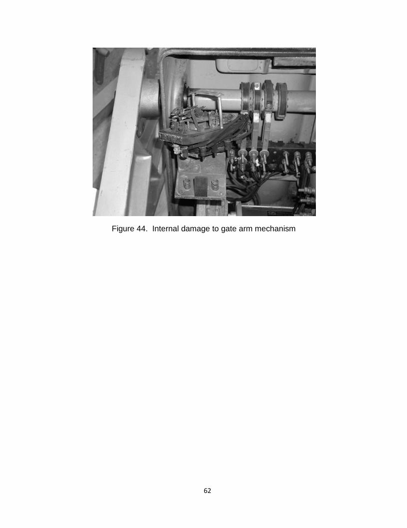
Figure 44. Internal damage to gate arm mechanism
1. 62
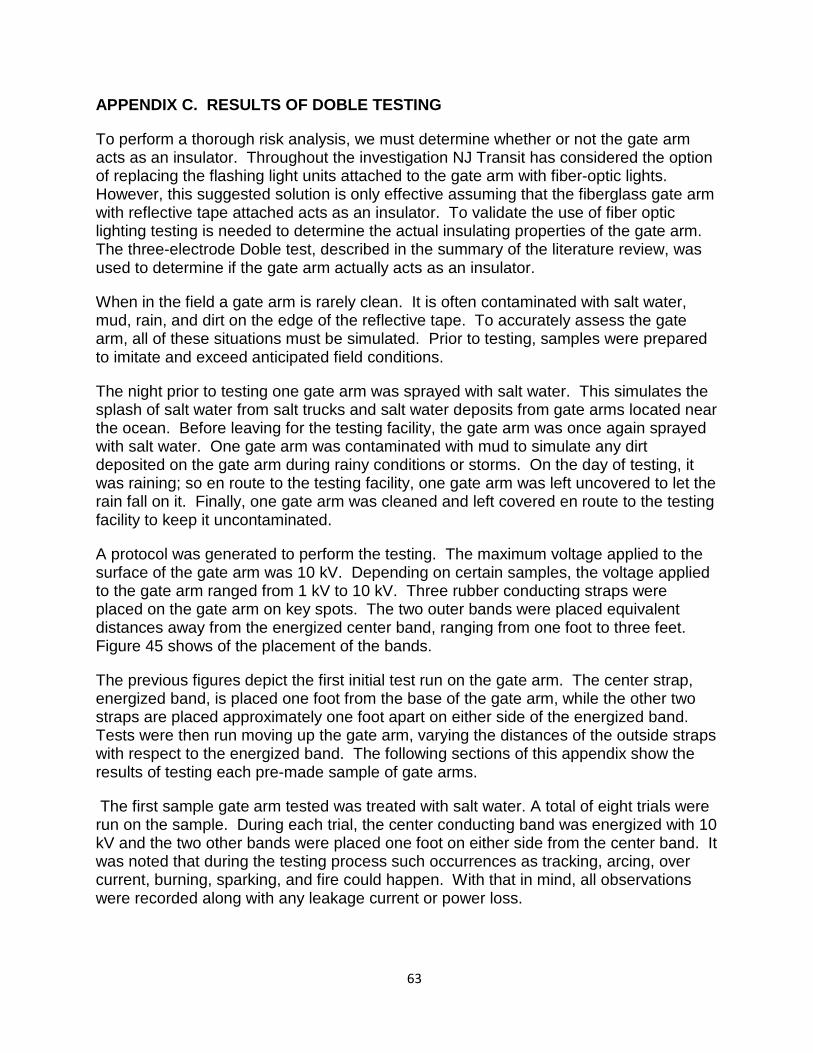
APPENDIX C. RESULTS OF DOBLE TESTING
To perform a thorough risk analysis, we must determine whether or not the gate arm acts as an insulator. Throughout the investigation NJ Transit has considered the option of replacing the flashing light units attached to the gate arm with fiber-optic lights. However, this suggested solution is only effective assuming that the fiberglass gate arm with reflective tape attached acts as an insulator. To validate the use of fiber optic lighting testing is needed to determine the actual insulating properties of the gate arm. The three-electrode Doble test, described in the summary of the literature review, was used to determine if the gate arm actually acts as an insulator.
When in the field a gate arm is rarely clean. It is often contaminated with salt water, mud, rain, and dirt on the edge of the reflective tape. To accurately assess the gate arm, all of these situations must be simulated. Prior to testing, samples were prepared to imitate and exceed anticipated field conditions.
The night prior to testing one gate arm was sprayed with salt water. This simulates the splash of salt water from salt trucks and salt water deposits from gate arms located near the ocean. Before leaving for the testing facility, the gate arm was once again sprayed with salt water. One gate arm was contaminated with mud to simulate any dirt deposited on the gate arm during rainy conditions or storms. On the day of testing, it was raining; so en route to the testing facility, one gate arm was left uncovered to let the rain fall on it. Finally, one gate arm was cleaned and left covered en route to the testing facility to keep it uncontaminated.
A protocol was generated to perform the testing. The maximum voltage applied to the surface of the gate arm was 10 kV. Depending on certain samples, the voltage applied to the gate arm ranged from 1 kV to 10 kV. Three rubber conducting straps were placed on the gate arm on key spots. The two outer bands were placed equivalent distances away from the energized center band, ranging from one foot to three feet. Figure 45 shows of the placement of the bands.
The previous figures depict the first initial test run on the gate arm. The center strap, energized band, is placed one foot from the base of the gate arm, while the other two straps are placed approximately one foot apart on either side of the energized band. Tests were then run moving up the gate arm, varying the distances of the outside straps with respect to the energized band. The following sections of this appendix show the results of testing each pre-made sample of gate arms.
The first sample gate arm tested was treated with salt water. A total of eight trials were run on the sample. During each trial, the center conducting band was energized with 10 kV and the two other bands were placed one foot on either side from the center band. It was noted that during the testing process such occurrences as tracking, arcing, over current, burning, sparking, and fire could happen. With that in mind, all observations were recorded along with any leakage current or power loss.
1. 63
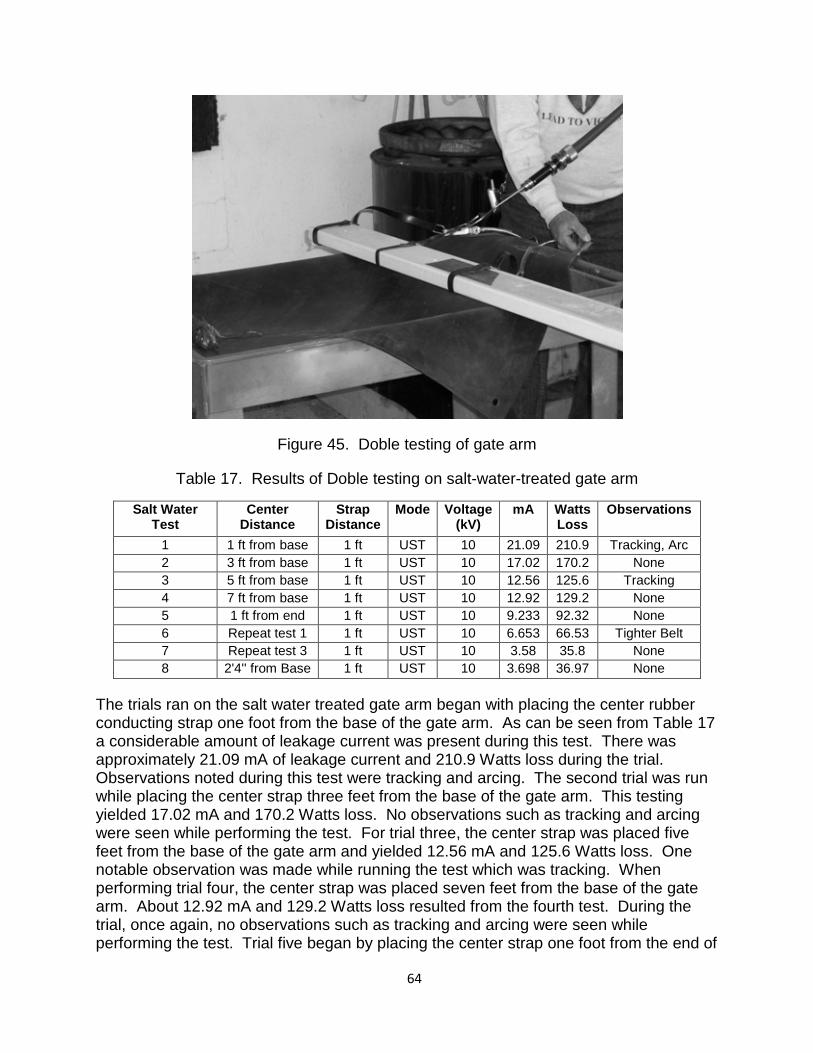
Figure 45. Doble testing of gate arm
Table 17. Results of Doble testing on salt-water-treated gate arm
Salt Water Test
Center Distance
Strap Distance
Mode Voltage (kV)
mA Watts Loss
Observations
1 1 ft from base 1 ft UST 10 21.09 210.9 Tracking, Arc 2 3 ft from base 1 ft UST 10 17.02 170.2 None 3 5 ft from base 1 ft UST 10 12.56 125.6 Tracking 4 7 ft from base 1 ft UST 10 12.92 129.2 None 5 1 ft from end 1 ft UST 10 9.233 92.32 None 6 Repeat test 1 1 ft UST 10 6.653 66.53 Tighter Belt 7 Repeat test 3 1 ft UST 10 3.58 35.8 None 8 2'4'' from Base 1 ft UST 10 3.698 36.97 None
The trials ran on the salt water treated gate arm began with placing the center rubber conducting strap one foot from the base of the gate arm. As can be seen from Table 17 a considerable amount of leakage current was present during this test. There was approximately 21.09 mA of leakage current and 210.9 Watts loss during the trial. Observations noted during this test were tracking and arcing. The second trial was run while placing the center strap three feet from the base of the gate arm. This testing yielded 17.02 mA and 170.2 Watts loss. No observations such as tracking and arcing were seen while performing the test. For trial three, the center strap was placed five feet from the base of the gate arm and yielded 12.56 mA and 125.6 Watts loss. One notable observation was made while running the test which was tracking. When performing trial four, the center strap was placed seven feet from the base of the gate arm. About 12.92 mA and 129.2 Watts loss resulted from the fourth test. During the trial, once again, no observations such as tracking and arcing were seen while performing the test. Trial five began by placing the center strap one foot from the end of
1. 64
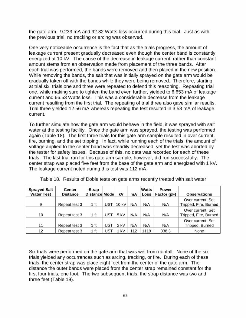
the gate arm. 9.233 mA and 92.32 Watts loss occurred during this trial. Just as with the previous trial, no tracking or arcing was observed.
One very noticeable occurrence is the fact that as the trials progress, the amount of leakage current present gradually decreased even though the center band is constantly energized at 10 kV. The cause of the decrease in leakage current, rather than constant amount stems from an observation made from placement of the three bands. After each trial was performed, the bands were removed and then placed in the new position. While removing the bands, the salt that was initially sprayed on the gate arm would be gradually taken off with the bands while they were being removed. Therefore, starting at trial six, trials one and three were repeated to defend this reasoning. Repeating trial one, while making sure to tighten the band even further, yielded to 6.653 mA of leakage current and 66.53 Watts loss. This was a considerable decrease from the leakage current resulting from the first trial. The repeating of trial three also gave similar results. Trial three yielded 12.56 mA whereas repeating the test resulted in 3.58 mA of leakage current.
To further simulate how the gate arm would behave in the field, it was sprayed with salt water at the testing facility. Once the gate arm was sprayed, the testing was performed again (Table 18). The first three trials for this gate arm sample resulted in over current, fire, burning, and the set tripping. In fact, while running each of the trials, the amount of voltage applied to the center band was steadily decreased, yet the test was aborted by the tester for safety issues. Because of this, no data was recorded for each of these trials. The last trial ran for this gate arm sample, however, did run successfully. The center strap was placed five feet from the base of the gate arm and energized with 1 kV. The leakage current noted during this test was 112 mA.
Table 18. Results of Doble tests on gate arms recently treated with salt water
Sprayed Salt Water Test
Center Distance
Strap Distance Mode kV mA
Watts Loss
Power Factor (pF) Observations
9 Repeat test 3 1 ft UST 10 kV N/A N/A N/A Over current, Set
Tripped, Fire, Burned
10 Repeat test 3 1 ft UST 5 kV N/A N/A N/A Over current, Set
Tripped, Fire, Burned
11 Repeat test 3 1 ft UST 2 kV N/A N/A N/A Over current, Set Tripped, Burned
12 Repeat test 3 1 ft UST 1 kV 112 1119 338.3 None
Six trials were performed on the gate arm that was wet from rainfall. None of the six trials yielded any occurrences such as arcing, tracking, or fire. During each of these trials, the center strap was place eight feet from the center of the gate arm. The distance the outer bands were placed from the center strap remained constant for the first four trials, one foot. The two subsequent trials, the strap distance was two and three feet (Table 19).
1. 65
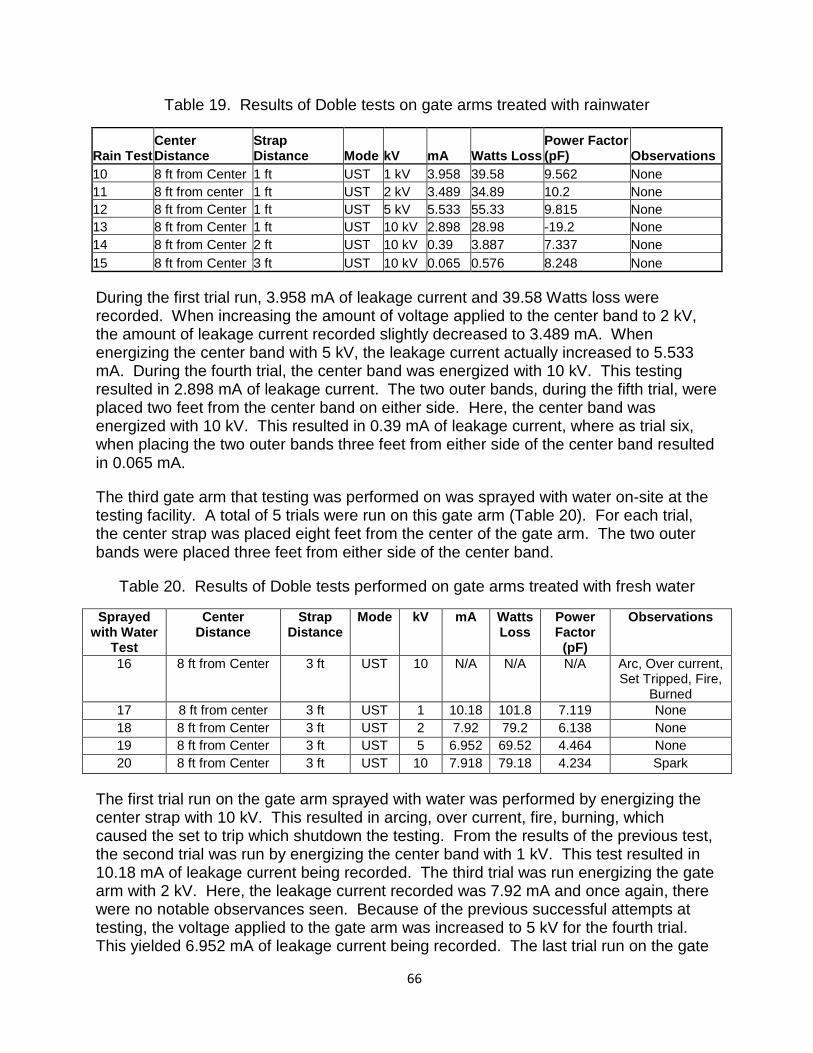
Table 19. Results of Doble tests on gate arms treated with rainwater
Rain Test Center Distance
Strap Distance Mode kV mA Watts Loss
Power Factor (pF) Observations
10 8 ft from Center 1 ft UST 1 kV 3.958 39.58 9.562 None 11 8 ft from center 1 ft UST 2 kV 3.489 34.89 10.2 None 12 8 ft from Center 1 ft UST 5 kV 5.533 55.33 9.815 None 13 8 ft from Center 1 ft UST 10 kV 2.898 28.98 -19.2 None 14 8 ft from Center 2 ft UST 10 kV 0.39 3.887 7.337 None 15 8 ft from Center 3 ft UST 10 kV 0.065 0.576 8.248 None
During the first trial run, 3.958 mA of leakage current and 39.58 Watts loss were recorded. When increasing the amount of voltage applied to the center band to 2 kV, the amount of leakage current recorded slightly decreased to 3.489 mA. When energizing the center band with 5 kV, the leakage current actually increased to 5.533 mA. During the fourth trial, the center band was energized with 10 kV. This testing resulted in 2.898 mA of leakage current. The two outer bands, during the fifth trial, were placed two feet from the center band on either side. Here, the center band was energized with 10 kV. This resulted in 0.39 mA of leakage current, where as trial six, when placing the two outer bands three feet from either side of the center band resulted in 0.065 mA.
The third gate arm that testing was performed on was sprayed with water on-site at the testing facility. A total of 5 trials were run on this gate arm (Table 20). For each trial, the center strap was placed eight feet from the center of the gate arm. The two outer bands were placed three feet from either side of the center band.
Table 20. Results of Doble tests performed on gate arms treated with fresh water
Sprayed with Water
Test
Center Distance
Strap Distance
Mode kV mA Watts Loss
Power Factor
(pF)
Observations
16 8 ft from Center 3 ft UST 10 N/A N/A N/A Arc, Over current, Set Tripped, Fire,
Burned 17 8 ft from center 3 ft UST 1 10.18 101.8 7.119 None 18 8 ft from Center 3 ft UST 2 7.92 79.2 6.138 None 19 8 ft from Center 3 ft UST 5 6.952 69.52 4.464 None 20 8 ft from Center 3 ft UST 10 7.918 79.18 4.234 Spark
The first trial run on the gate arm sprayed with water was performed by energizing the center strap with 10 kV. This resulted in arcing, over current, fire, burning, which caused the set to trip which shutdown the testing. From the results of the previous test, the second trial was run by energizing the center band with 1 kV. This test resulted in 10.18 mA of leakage current being recorded. The third trial was run energizing the gate arm with 2 kV. Here, the leakage current recorded was 7.92 mA and once again, there were no notable observances seen. Because of the previous successful attempts at testing, the voltage applied to the gate arm was increased to 5 kV for the fourth trial. This yielded 6.952 mA of leakage current being recorded. The last trial run on the gate
1. 66
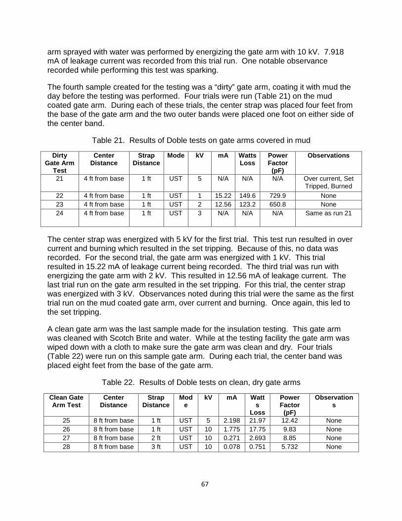
arm sprayed with water was performed by energizing the gate arm with 10 kV. 7.918 mA of leakage current was recorded from this trial run. One notable observance recorded while performing this test was sparking.
The fourth sample created for the testing was a “dirty” gate arm, coating it with mud the day before the testing was performed. Four trials were run (Table 21) on the mud coated gate arm. During each of these trials, the center strap was placed four feet from the base of the gate arm and the two outer bands were placed one foot on either side of the center band.
Table 21. Results of Doble tests on gate arms covered in mud
Dirty Gate Arm
Test
Center Distance
Strap Distance
Mode kV mA Watts Loss
Power Factor
(pF)
Observations
21 4 ft from base 1 ft UST 5 N/A N/A N/A Over current, Set Tripped, Burned
22 4 ft from base 1 ft UST 1 15.22 149.6 729.9 None 23 4 ft from base 1 ft UST 2 12.56 123.2 650.8 None 24 4 ft from base 1 ft UST 3 N/A N/A N/A Same as run 21
The center strap was energized with 5 kV for the first trial. This test run resulted in over current and burning which resulted in the set tripping. Because of this, no data was recorded. For the second trial, the gate arm was energized with 1 kV. This trial resulted in 15.22 mA of leakage current being recorded. The third trial was run with energizing the gate arm with 2 kV. This resulted in 12.56 mA of leakage current. The last trial run on the gate arm resulted in the set tripping. For this trial, the center strap was energized with 3 kV. Observances noted during this trial were the same as the first trial run on the mud coated gate arm, over current and burning. Once again, this led to the set tripping.
A clean gate arm was the last sample made for the insulation testing. This gate arm was cleaned with Scotch Brite and water. While at the testing facility the gate arm was wiped down with a cloth to make sure the gate arm was clean and dry. Four trials (Table 22) were run on this sample gate arm. During each trial, the center band was placed eight feet from the base of the gate arm.
Table 22. Results of Doble tests on clean, dry gate arms
Clean Gate Arm Test
Center Distance
Strap Distance
Mode
kV mA Watts
Loss
Power Factor
(pF)
Observations
25 8 ft from base 1 ft UST 5 2.198 21.97 12.42 None 26 8 ft from base 1 ft UST 10 1.775 17.75 9.83 None 27 8 ft from base 2 ft UST 10 0.271 2.693 8.85 None 28 8 ft from base 3 ft UST 10 0.078 0.751 5.732 None
1. 67
This first trial run on the gate arm was performed by applying 5 kV to the center band of the gate arm and the outer bands were placed one foot from either side of the center band. 2.198 mA of leakage current were recorded from this trial run. Because the test ran successfully the voltage applied to the center strap was increased to 10 kV for the remainder of the trials. The second trial was run by placing the outer bands one foot from either side of the center band. 1.775 mA of leakage current was recorded during this test. During the third trial, the outer bands were placed two feet from either side of the center band. This resulted in 0.271 mA of leakage current being recorded. The final trial was run by placing the outer bands three feet from either side of the center band. This resulted in 0.078 mA of leakage current being recorded.
These data suggest that a clean gate arm does act as an effective insulator. However as dirt accumulates on the gate arm, it becomes more conductive. As the approach taken in this study is to assume worst case scenarios, the possibility that a gate arm will be coated in water, dirt or salt, and is therefore conductive, must be considered. Therefore, the fiberglass gate arm itself is considered to be a potential path for line to ground faults, regardless of the presence of lighting wires. With this said, an alternative to lighting on the gate arm would not completely remove the risk of a line-to-earth fault from occurring.
The electrical testing performed on the surface of the gate arm helped understand how the gate arm acts when in operation throughout NJT’s service region. In the field, the gate arm is rarely ever clean and usually contains salt, dirt, and becomes wet during rainfall. Under these conditions the gate arm and environmentally deposited material can have insulating properties different from a clean gate arm. When voltage was applied to the surface of the gate arm, a considerable amount of leakage current was recorded. One notable observation as to why this was happening revolves around the reflective tape on the gate arm. The edges of the reflective tape appeared to have a buildup of dirt and grime edged into it. This aids in developing a path to ground when a gate arm contacts the catenary wires.
The only time when the gate arm appeared to act as an insulator is when it was in a clean condition. When applying the high voltage to the surface of the clean gate arm led to no leakage current found on the arm, where as a muddy gate arm led to so much leakage current, the testing was stopped by the test operator. From the results of the analysis, it is apparent that using fiber optic lighting instead of the flashing light units would not reduce the risk of a line-to-earth fault. However, periodic cleaning of gate arms for the most at risk sites may be a viable preventative step in minimizing the likelihood of line-to-earth faults.
1. 68
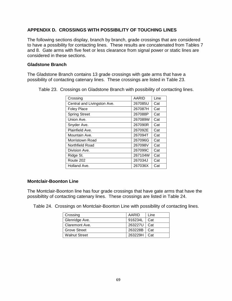
APPENDIX D. CROSSINGS WITH POSSIBILITY OF TOUCHING LINES
The following sections display, branch by branch, grade crossings that are considered to have a possibility for contacting lines. These results are concatenated from Tables 7 and 8. Gate arms with five feet or less clearance from signal power or static lines are considered in these sections.
Gladstone Branch
The Gladstone Branch contains 13 grade crossings with gate arms that have a possibility of contacting catenary lines. These crossings are listed in Table 23.
Table 23. Crossings on Gladstone Branch with possibility of contacting lines.
Crossing AARID Line Central and Livingston Ave. 267085U Cat Foley Place 267087H Cat Spring Street 267088P Cat Union Ave. 267089W Cat Snyder Ave. 267090R Cat Plainfield Ave. 267092E Cat Mountain Ave. 267094T Cat Morristown Road 267096G Cat Northfield Road 267098V Cat Division Ave. 267099C Cat Ridge St. 267104W Cat Route 202 267034J Cat Holland Ave. 267036X Cat
Montclair-Boonton Line
The Montclair-Boonton line has four grade crossings that have gate arms that have the possibiltity of contacting catenary lines. These crossings are listed in Table 24.
Table 24. Crossings on Montclair-Boonton Line with possibility of contacting lines.
Crossing AARID Line Glenridge Ave. 916234L Cat Claremont Ave. 263227U Cat Grove Street 263228B Cat Walnut Street 263229H Cat
1. 69
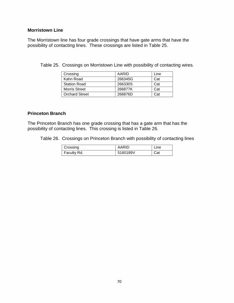
Morristown Line
The Morristown line has four grade crossings that have gate arms that have the possibility of contacting lines. These crossings are listed in Table 25.
Table 25. Crossings on Morristown Line with possibility of contacting wires.
Crossing AARID Line Kahn Road 266345G Cat Station Road 266330S Cat Morris Street 266877K Cat Orchard Street 266876D Cat
Princeton Branch
The Princeton Branch has one grade crossing that has a gate arm that has the possibility of contacting lines. This crossing is listed in Table 26.
Table 26. Crossings on Princeton Branch with possibility of contacting lines
Crossing AARID Line Faculty Rd. 5160189V Cat
1. 70
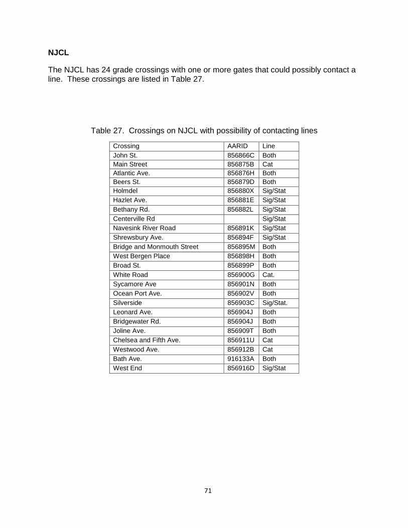
NJCL
The NJCL has 24 grade crossings with one or more gates that could possibly contact a line. These crossings are listed in Table 27.
Table 27. Crossings on NJCL with possibility of contacting lines
Crossing AARID Line John St. 856866C Both Main Street 856875B Cat Atlantic Ave. 856876H Both Beers St. 856879D Both Holmdel 856880X Sig/Stat Hazlet Ave. 856881E Sig/Stat Bethany Rd. 856882L Sig/Stat Centerville Rd Sig/Stat Navesink River Road 856891K Sig/Stat Shrewsbury Ave. 856894F Sig/Stat Bridge and Monmouth Street 856895M Both West Bergen Place 856898H Both Broad St. 856899P Both White Road 856900G Cat. Sycamore Ave 856901N Both Ocean Port Ave. 856902V Both Silverside 856903C Sig/Stat. Leonard Ave. 856904J Both Bridgewater Rd. 856904J Both Joline Ave. 856909T Both Chelsea and Fifth Ave. 856911U Cat Westwood Ave. 856912B Cat Bath Ave. 916133A Both West End 856916D Sig/Stat
1. 71