Embed Size (px)
Citation preview
JOURNAL OF MATERIALS AND ENGINEERING STRUCTURES 2 (2015) 57–67 57
Research Paper
Comparison Study of Axial Behavior of RPC-CFRP Short Columns
Taghreed Kh. Mohammad Ali a,*, Maha M. S. Ridha b, Zinah Asaad b, Layla A. Gh.Yaseen b
a Architecture Department, Engineering Faculty, Koya University, Arbil, Iraq b Structural Engineering Division, Building and Construction Engineering Department, University Technology, Baghdad, Iraq
A R T I C L E I N F O
Article history:
Received 11 December 2014
Revised 16 March 2015
Accepted 28 March 2015
Keywords:
carbon fiber;
reinforced polymer;
short columns;
reactive powder concrete;
wrapping.
A B S T R A C T
In this paper, the axial behaviors of reactive powder concrete (RPC) short columns confined with carbon fiber reinforced polymer (CFRP) were investigated. All the specimens have square cross section of 100 mm × 100 mm and length of 400 mm with aspect ratio 4. The experimental work consists of three groups. The first group consists of six specimens of RPC with 2% micro steel fiber, without ordinary reinforcing steel and confining by zero, one and two layer of CFRP respectively. The second group consists of six specimens of RPC with 2% micro steel fiber and minimum ordinary reinforcing steel and confining by zero, one and two layers of CFRP respectively. The third group consists of four specimens of RPC without micro steel fiber and ordinary reinforcing steel and confining by one and two layers of CFRP respectively. Experimental data for strength, longitudinal and lateral displacement and failure mode were obtained for each test. The toughness (area under the curve) for each test was obtained by using numerical integration. The RPC columns confined with CFRP showed stiffer behavior compared with RPC columns without CFRP. The ultimate load of the RPC columns with 2% micro steel fiber + two layers of CFRP + minimum ordinary reinforcement were more than that of the RPC columns with 2% micro steel fiber + minimum ordinary reinforcement and without CFRP by about 1.333.
1 Introduction
The development of reinforcement technology is becoming more advanced as engineers started to use other than just steel reinforced concrete in their designs. In recent years, Fiber Reinforced Polymer (FRP) has been proposed as one of the main materials in reinforced concrete. The benefits of using FRP in reinforced concrete depends on some factor such as shape, length, cross section, fiber content and bond characteristics of FRP [1].
* Corresponding author. Tel: +964771428729. E-mail address: [email protected] e-ISSN: 2170-127X, © Mouloud Mammeri University of Tizi-Ouzou, Algeria
58 JOURNAL OF MATERIALS AND ENGINEERING STRUCTURES 2 (2015)57–67
FRP wrapping has several advantages, including extremely low weight-to-strength ratios, high elastic moduli, resistance to corrosion, and ease of application. In addition, unidirectional FRP wrapping can improve column ductility without considerable stiffness amplification [2].
Commonly employed FRP composite materials are carbon fiber reinforced polymer (CFRP), glass fiber reinforced polymer (GFRP) and aramid fiber reinforced polymer (AFRP). Most FRP materials exhibit nearly linear elastic behavior up to failure. In general, CFRP has a higher modulus of elasticity than AFRP and GFRP. In terms of tensile strength, CFRP has the highest strength, followed by AFRP and GFRP.
With FRP wraps, the confining layer is very thin and is applied directly onto the surface of the column. The composite wraps are flexible and can be handled and cut with little effort. Alternatively, FRP may be used as a permanent formwork and used with other high-performance materials, such as reactive powder concrete (RPC), to produce a high-performance composite material.
Reactive powder concrete (RPC) is a new generation cementations composite material with ultra-high performance [3]. It is characterized by its extremely superior physical properties, particularly the ultra-high strength and good ductility. Enhanced properties of RPC are obtained through grain size optimization, incorporation of micro-silica and post-set heat-treating. Compressive strength of RPC can range from 200MPa to 800MPa. By introducing micro steel fibers, RPC can achieve remarkable flexural strength up to 50MPa. The material exhibits high ductility, more than 250 times greater than that of conventional concrete [4].
It is feasible to apply RPC to the construction of bridge columns for better seismic performance. RPC columns may become lighter due to ultra-high strength of RPC and seismic inertia loads may be reduced. Ductility of RPC columns can be improved because of high flexural strength and fracture energy absorption capacity of RPC. Consequently, the amount of lateral reinforcement for confinement in columns can be reduced greatly.
There are different researches on the effect of using FRP for strengthening concrete columns. Song, and et al [5] found that the maximum compression load of FRP-strengthened concrete square or rectangular columns is increased linearly with the amount of FRP sheets used and decreases linearly with the load eccentricity and exponentially with the concrete compression strength. The effectiveness of the CFRP confinement is significantly affected by load eccentricity. El-Maaddawy, et al [6] got CFRP confinement is less effective under eccentric loading relative to concentric loading. Jiang, and Teng [7] found that the improvement in the load capacity under uniaxial eccentric loading is more significant at small load eccentricities. Few researchers investigated the performance of CFRP-confined RC columns under biaxial eccentric loading. One and two layers of CFRP confinement resulted in approximately 22 and 26% increase in the load capacity, respectively, for RC columns with a square cross section of 76 × 76 mm under biaxial eccentric loading with ex/bx = ey/by = 0.67 [8].
The objective of this research was to examine the behavior of square short RPC columns confined with carbon fiber-reinforced polymer (CFRP) to determine the strength, toughness and stiffness provided by the CFRP, with and without conventional reinforcement. For this purpose, sixteen columns were cast and tested under concentric loading and the results were reported herein. These results may form an important data set for future development of design models for this unique combination of materials.
2 Research significance
Most of the experimental, analytical, and numerical studies conducted on FRP confined columns are based on conventional strength concrete, with limited research for high-strength concrete (HSC) [9]. Very little experimental data is available for the development of models for ultra-high-performance concrete confined with CFRP. The significant benefit of the research is to investigate the effect of micro steel fiber, ordinary reinforcement and amount of layers of CFRP on the loading capacity of axially short square columns, longitudinal deflection, lateral deflection and toughness of these columns.
JOURNAL OF MATERIALS AND ENGINEERING STRUCTURES2 (2015) 57–67 59
3 Experimental program
The experimental work consists of three groups. Group-1 consists of six RPC short square columns, with 2% micro steel fiber and without ordinary reinforcement, surrounded by none, one or two layer of CFRP. Group-2 consists of four RPC short square columns, without micro steel fiber and ordinary reinforcement, surrounded by one or two layers of CFRP. While, Group 3 consists of six RPC short square columns with 2% micro steel fiber and minimum ordinary reinforcement surrounded by none, one or two layer of CFRP.
3.1 Materials and mix design
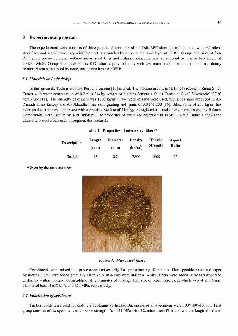
In this research, Tasloja ordinary Portland cement [10] is used. The mixture used was (1:1:0.25) (Cement: Sand: Silica Fume) with water cement ratio of 0.2 plus 2% by weight of binder (Cement + Silica Fume) of Sika® Viscocrete® PC20 admixture [11]. The quantity of cement was 1000 kg/m3. Two types of sand were used, fine silica sand produced in Al-Ramadi Glass factory and Al-Ukhaidher fine sand grading and limits of ASTM C33 [10]. Silica fume of 250 kg/m3 has been used as a mineral admixture with a Specific Surface of 21m2/g. Straight micro steel fibers, manufactured by Bekaert Corporation, were used in the RPC mixture. The properties of fibers are described in Table 1, while Figure 1 shows the ultra-micro steel fibers used throughout this research.
Table 1: Properties of micro steel fibers*
Description Length
(mm)
Diameter
(mm)
Density
(kg/m3)
Tensile Strength
Aspect Ratio
Straight 13 0.2 7800 2600 65
*Given by the manufacturer
Figure 1: Micro steel fibers
Constituents were mixed in a pan concrete mixer drily for approximately 10 minutes. Then, potable water and super plasticizer PC20 were added gradually till mixture materials were uniform. Whilst, fibers were added lastly and dispersed uniformly within mixture for an additional ten minutes of mixing. Two size of rebar were used, which were 4 and 6 mm plain steel bars of 638 MPa and 520 MPa, respectively.
3.2 Fabrication of specimens
Timber molds were used for casting all columns vertically. Dimension of all specimens were 100×100×400mm. First group consists of six specimens of concrete strength f’c =121 MPa with 2% micro steel fiber and without longitudinal and
60 JOURNAL OF MATERIALS AND ENGINEERING STRUCTURES 2 (2015)57–67
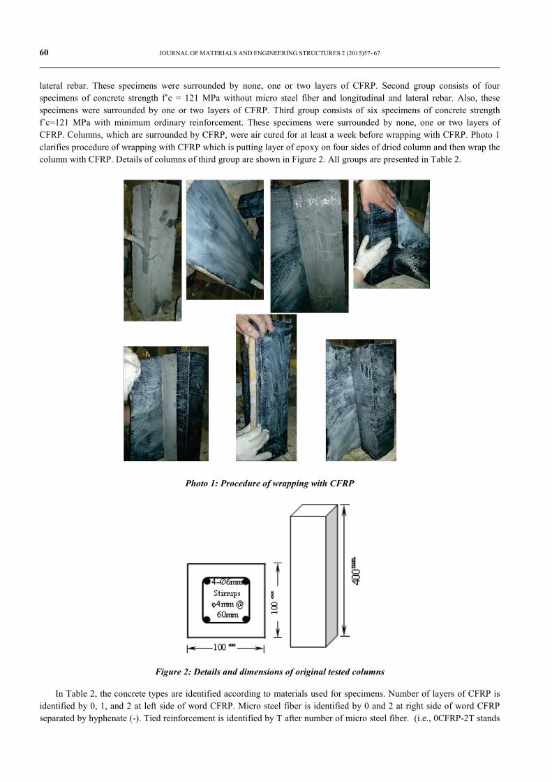
lateral rebar. These specimens were surrounded by none, one or two layers of CFRP. Second group consists of four specimens of concrete strength f’c = 121 MPa without micro steel fiber and longitudinal and lateral rebar. Also, these specimens were surrounded by one or two layers of CFRP. Third group consists of six specimens of concrete strength f’c=121 MPa with minimum ordinary reinforcement. These specimens were surrounded by none, one or two layers of CFRP. Columns, which are surrounded by CFRP, were air cured for at least a week before wrapping with CFRP. Photo 1 clarifies procedure of wrapping with CFRP which is putting layer of epoxy on four sides of dried column and then wrap the column with CFRP. Details of columns of third group are shown in Figure 2. All groups are presented in Table 2.
Photo 1: Procedure of wrapping with CFRP
Figure 2: Details and dimensions of original tested columns
In Table 2, the concrete types are identified according to materials used for specimens. Number of layers of CFRP is identified by 0, 1, and 2 at left side of word CFRP. Micro steel fiber is identified by 0 and 2 at right side of word CFRP separated by hyphenate (-). Tied reinforcement is identified by T after number of micro steel fiber. (i.e., 0CFRP-2T stands
JOURNAL OF MATERIALS AND ENGINEERING STRUCTURES2 (2015) 57–67 61
for RPC retrofitted column without CFRP and with 2% of micro steel fiber and ordinary tied rebar). Three 200×100 mm cylinders were prepared from each batch and used for determining compressive strength (f'c) at age of 28 days.
Table 2: Details of tested columns
Groups Name of
Specimens No. of
Specimens
Percentage of Micro
steel fibers
f'c
(Mpa)
Longitudinal Steel Bars
Tie Bars
Group-1
0CFRP-2 2 2% 121 0 0
1CFRP-2 2 2% 121 0 0
2CFRP-2 2 2% 121 0 0
Group-2 1CFRP-0 2 0 100 0 0
2CFRP-0 2 0 100 0 0
Group-3
0CFRP-2T 2 2% 121 4 – Ø6 Ø4mm @ 60mm
1CFRP-2T 2 2% 121 4 – Ø6 Ø4mm @ 60mm
2CFRP-2T 2 2% 121 4 – Ø6 Ø4mm @ 60mm
3.3 Curing of columns
After 24 hours, all RPC specimens were stripped and cured for 48 hours at 70°C in a hot water bath. Then, specimens were removed from hot water bath and left to be cooled at room temperature, then placed in water and left until end of water curing at 28 days. Finally, specimens were wrapped with CFRP layers according to experimental program, and tested to failure after a week.
3.4 CFRP used at works
CFRP product used in this research is a woven carbon fiber fabric for structural strengthening called (SikaWrap®-230 C/45) which is a unidirectional woven carbon fiber fabric for dry application process supplied by Sika Materials Company in Baghdad [12], and resin used for bonding of CFRP was a two-part epoxy adhesive and it was applied with a total thickness equal to 1 mm. Mechanical properties of used CFRP as given by the manufacturer are presented in Table 3.
Table 3: Properties of SikaWrap-230 C/45 (CFRP) [12]*
Fabric Type Mid strength carbon fibers
Fabric Construction Fiber Orientation: 0O (unidirectional).Wrap: black carbon fibers (99% of total areal
weight).
Technical Data
Areal Weight, g/m2 230 ± 10 Fabric Design Thickness, mm 0.131
Fiber Density, g/cm3 1.76 Mechanical / Physical Properties:
Tensile strength, MPa 4300
Modulus of Elasticity, GPa 234
Elongation at break 1.8%
*Given by the manufacturer
62 JOURNAL OF MATERIALS AND ENGINEERING STRUCTURES 2 (2015)57–67
4 Loading Setup and Measurements
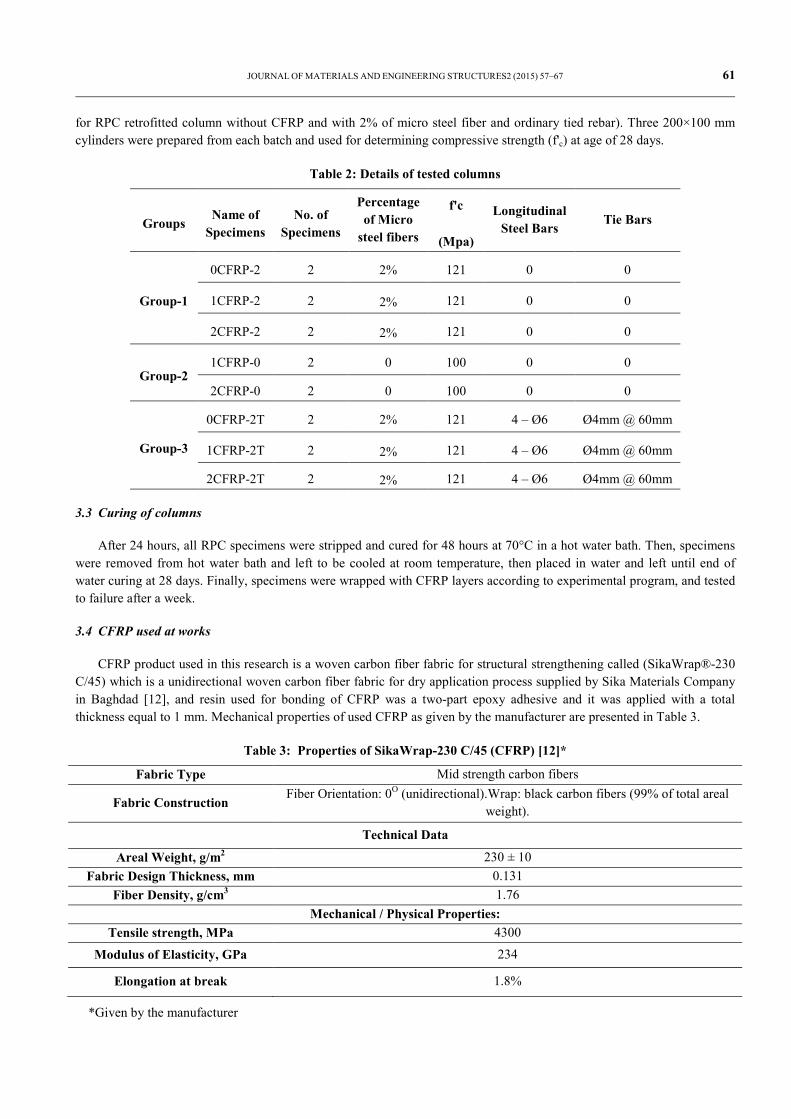
Vertical displacements along columns were measured using dial gage. Demec points were used to measure surface strains of concrete. Two demec gage points were mounted at spacing of 100 mm at the column mid-height along column vertical axis to measure longitudinal compressive strains at two perpendiculars faces of column. Also additional two demecs were mounted horizontally at spacing of 100 mm to measure lateral strains at two perpendicular faces of column.
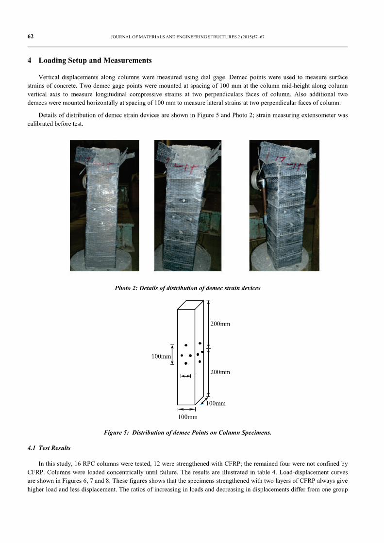
Details of distribution of demec strain devices are shown in Figure 5 and Photo 2; strain measuring extensometer was calibrated before test.
Photo 2: Details of distribution of demec strain devices
Figure 5: Distribution of demec Points on Column Specimens.
4.1 Test Results
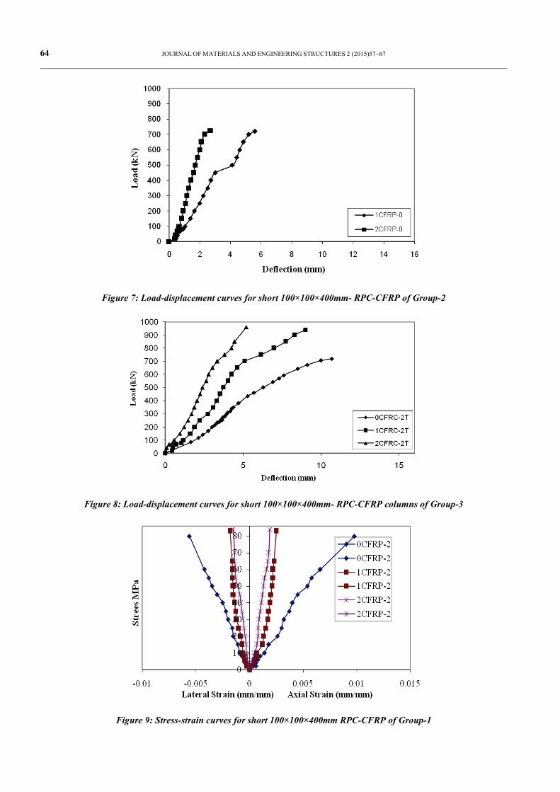
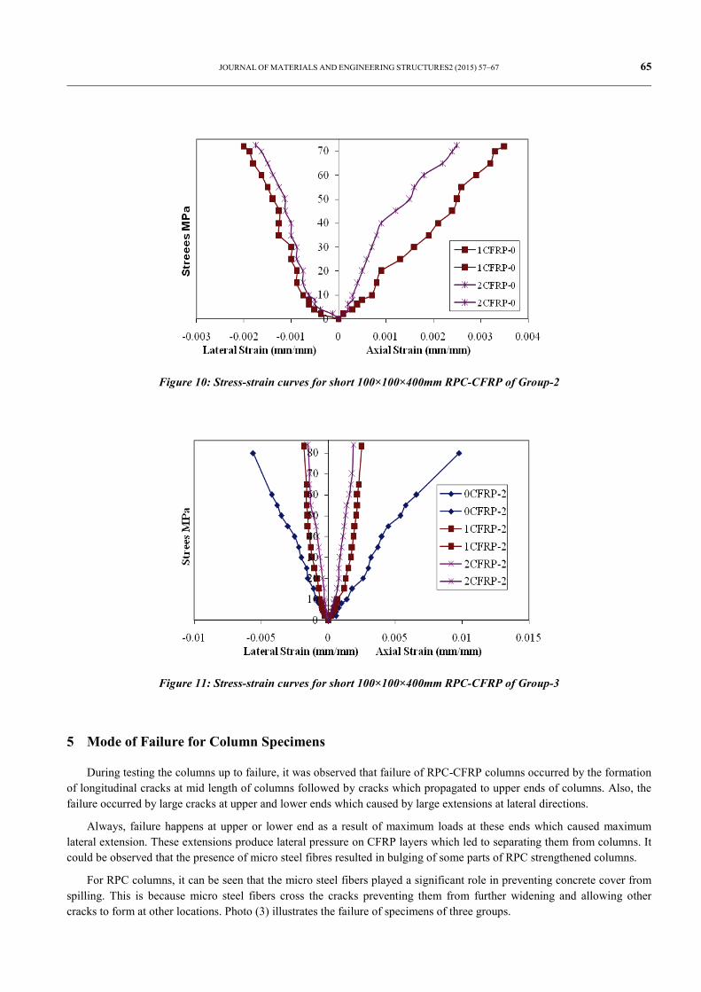
In this study, 16 RPC columns were tested, 12 were strengthened with CFRP; the remained four were not confined by CFRP. Columns were loaded concentrically until failure. The results are illustrated in table 4. Load-displacement curves are shown in Figures 6, 7 and 8. These figures shows that the specimens strengthened with two layers of CFRP always give higher load and less displacement. The ratios of increasing in loads and decreasing in displacements differ from one group
100mm
m
100mm
200mm
200mm
100mm

JOURNAL OF MATERIALS AND ENGINEERING STRUCTURES2 (2015) 57–67 63
to another. For example, for specimen 2CFRP-2T of group-3, the maximum increasing in load was 33.33% and the decreasing in displacement was 51.40%. Stress- strain curves of axial and lateral strain are shown in Figures 9, 10 and 11.
In this study the modulus of toughness [13] for both longitudinal and lateral directions is calculated. The modulus of toughness is the total area up to fracture and the energy to break a unit volume of material. It is approximated by the area under the stress-strain curve.
Table 4: Average failure loads and strength for tested columns
Groups Name of
Specimens Ultimate
Load (kN)
Ultimate Strength
(MPa)
Modulus of Toughness-
Longitudinal Direction
(MPa)
Modulus of
Toughness- Lateral
Direction
(MPa)
Group-1
0CFRP-2 800 80 0.42823 -0.22921
1CFRP-2 830 83 0.078696 -0.05466
2CFRP-2 840 84 0.071652 -0.010825
Group-2 1CFRP-0 720 72 0.124975 -0.07289
2CFRP-0 725 72.5 0.097728 -0.06493
Group-3
0CFRP-2T 720 72 0.858506 -0.28175
1CFRP-2T 940 94 0.146367 -0.11027
2CFRP-2T 960 96 0.094402 -0.081
Figure 6: Load-displacement curves for short 100×100×400mm- RPC-CFRP columns of Group-1
64 JOURNAL OF MATERIALS AND ENGINEERING STRUCTURES 2 (2015)57–67
Figure 7: Load-displacement curves for short 100×100×400mm- RPC-CFRP of Group-2
Figure 8: Load-displacement curves for short 100×100×400mm- RPC-CFRP columns of Group-3
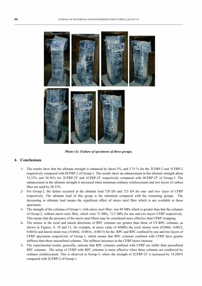
Figure 9: Stress-strain curves for short 100×100×400mm RPC-CFRP of Group-1
JOURNAL OF MATERIALS AND ENGINEERING STRUCTURES2 (2015) 57–67 65
Figure 10: Stress-strain curves for short 100×100×400mm RPC-CFRP of Group-2
Figure 11: Stress-strain curves for short 100×100×400mm RPC-CFRP of Group-3
5 Mode of Failure for Column Specimens
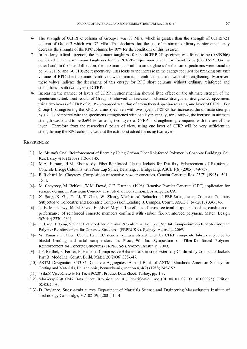
During testing the columns up to failure, it was observed that failure of RPC-CFRP columns occurred by the formation of longitudinal cracks at mid length of columns followed by cracks which propagated to upper ends of columns. Also, the failure occurred by large cracks at upper and lower ends which caused by large extensions at lateral directions.
Always, failure happens at upper or lower end as a result of maximum loads at these ends which caused maximum lateral extension. These extensions produce lateral pressure on CFRP layers which led to separating them from columns. It could be observed that the presence of micro steel fibres resulted in bulging of some parts of RPC strengthened columns.
For RPC columns, it can be seen that the micro steel fibers played a significant role in preventing concrete cover from spilling. This is because micro steel fibers cross the cracks preventing them from further widening and allowing other cracks to form at other locations. Photo (3) illustrates the failure of specimens of three groups.
66 JOURNAL OF MATERIALS AND ENGINEERING STRUCTURES 2 (2015)57–67
Photo (3): Failure of specimens of three groups.
6 Conclusions
1- The results show that the ultimate strength is enhanced by about 5%, and 3.75 % for the 2CFRP-2 and 1CFRP-2 respectively compared with 0CFRP-2 of Group-1. The results show an enhancement in the ultimate strength about 33.33% and 30.56% for 2CFRP-2T and 1CFRP-2T respectively compared with 0CFRP-2T of Group-3. The enhancement in the ultimate strength is increased when minimum ordinary reinforcement and two layers of carbon fiber are used by 28.33%.
2- For Group-2, the failure occurred at the ultimate load 720 kN and 725 kN for one- and two- layer of CFRP respectively. The ultimate load of this group is the minimum compared with the remaining groups. The decreasing in ultimate load means the significant effect of micro steel fiber which is not available at these specimens.
3- The strength of the columns of Group-1, with micro steel fiber, was 80 MPa which is greater than that the columns of Group-2, without micro steel fiber, which were 72 MPa, 72.5 MPa for one and two layers CFRP respectively. This means that the presence of the micro steel fibers may be considered more effective than CFRP wrapping.
4- The strains in the axial and lateral directions of RPC columns are greater than those of CF-RPC columns, as shown in Figures. 9, 10 and 11, for example, at stress value of 60MPa the axial strains were (0.0066, 0.0022, 0.0016) and lateral strain was (-0.0042, -0.0016, -0.0013) for the RPC and RPC confined by one and two layers of CFRP specimens respectively of Group-1; which means that RPC columns confined with CFRP have greater stiffness than those unconfined columns. The stiffness increases as the CFRP layers increase.
5- The experimental results, generally, indicate that RPC columns confined with CFRP are stiffer than unconfined RPC columns. The using of CFRP with RPC columns is more effective when these columns are reinforced by ordinary reinforcement. This is observed in Group-3; where the strength of 2CFRP-2T is increased by 14.286% compared with 2CFRP-2 of Group-1.
JOURNAL OF MATERIALS AND ENGINEERING STRUCTURES2 (2015) 57–67 67
6- The strength of 0CFRP-2 column of Group-1 was 80 MPa, which is greater than the strength of 0CFRP-2T column of Group-3 which was 72 MPa. This declares that the use of minimum ordinary reinforcement may decrease the strength of the RPC columns by 10% for the conditions of this research.
7- In the longitudinal direction, the maximum toughness for the 0CFRP-2T specimen was found to be (0.858506) compared with the minimum toughness for the 2CFRP-2 specimen which was found to be (0.071652). On the other hand, in the lateral direction, the maximum and minimum toughness for the same specimens were found to be (-0.28175) and (-0.010825) respectively. This leads to the increase in the energy required for breaking one unit volume of RPC short columns reinforced with minimum reinforcement and without strengthening. Moreover, these values indicate the decreasing of this energy for RPC short columns without ordinary reinforced and strengthened with two layers of CFRP.
8- Increasing the number of layers of CFRP in strengthening showed little effect on the ultimate strength of the specimens tested. Test results of Group -3, showed an increase in ultimate strength of strengthened specimens using two layers of CFRP of 2.13% compared with that of strengthened specimens using one layer of CFRP . For Group-1, strengthening the RPC columns specimen with two layers of CFRP has increased the ultimate strength by 1.21 % compared with the specimens strengthened with one layer. Finally, for Group-2, the increase in ultimate strength was found to be 0.694 % for using two layers of CFRP in strengthening, compared with the use of one layer. Therefore from the researchers’ points of view, using one layer of CFRP will be very sufficient in strengthening the RPC columns, without the extra cost added for using two layers.
REFERENCES
[1]- M. Mustafa Önal, Reinforcement of Beam by Using Carbon Fiber Reinforced Polymer in Concrete Buildings. Sci. Res. Essay 4(10) (2009) 1136-1145.
[2]- M.A. Haroun, H.M. Elsanadedy, Fiber-Reinforced Plastic Jackets for Ductility Enhancement of Reinforced Concrete Bridge Columns with Poor Lap Splice Detailing, J. Bridge Eng. ASCE 1(6) (2005) 749-757.
[3]- P. Richard, M. Cheyrezy, Composition of reactive powder concretes. Cement Concrete Res. 25(7) (1995) 1501–1511.
[4]- M. Cheyrezy, M. Behloul, W.M. Dowd, C.E. Dauriac, (1998). Reactive Powder Concrete (RPC) application for seismic design. In American Concrete Institute-Fall Convention, Los Angeles, CA.
[5]- X. Song, X. Gu, Y. Li, T. Chen, W. Zhang, Mechanical Behavior of FRP-Strengthened Concrete Columns Subjected to Concentric and Eccentric Compression Loading, J. Compos. Constr. ASCE 17(4)(2013) 336-346.
[6]- T. El-Maaddawy, M. El-Sayed, B. Abdel-Magid, The effects of cross-sectional shape and loading condition on performance of reinforced concrete members confined with carbon fiber-reinforced polymers. Mater. Design 5(2010) 2330–2341.
[7]- T. Jiang, J. Teng, Slender FRP-confined circular RC columns. In: Proc., 9th Int. Symposium on Fiber-Reinforced Polymer Reinforcement for Concrete Structures (FRPRCS-9), Sydney, Australia, 2009.
[8]- W. Punurai, J. Chen, C.T.T. Hsu, RC slender columns strengthened by CFRP composite fabrics subjected to biaxial bending and axial compression. In: Proc., 9th Int. Symposium on Fiber-Reinforced Polymer Reinforcement for Concrete Structures (FRPRCS-9), Sydney, Australia, 2009.
[9]- J.F. Berthet, E. Ferrier, P. Hamelin, Compressive Behavior of Concrete Externally Confined by Composite Jackets Part B: Modeling, Constr. Build. Mater. 20(2006) 338-347.
[10]- ASTM Designation C33-86, Concrete Aggregates, Annual Book of ASTM, Standards American Society for Testing and Materials, Philadelphia, Pennsylvania, section 4, 4(2) (1988) 245-252.
[11]- "Sika® ViscoCrete ® Hi-Tech PC20", Product Data Sheet, Turkey, pp. 1-3. [12]- SikaWrap-230 C/45 Data Sheet, Revision no: 01, Identification no: (01 04 01 02 001 0 000025), Edition
02/03/2009. [13]- D. Roylance, Stress-strain curves, Department of Materials Science and Engineering Massachusetts Institute of
Technology Cambridge, MA 02139, (2001) 1-14.