Embed Size (px)
Citation preview
White Paper
All contents are Copyright © 1992–2007 Cisco Systems, Inc. All rights reserved. This document is Cisco Public Information. Page 1 of 51
Comparison of the Cisco Catalyst and Cisco IOS Software Operating Systems for Cisco Catalyst 6500 Series Switches
Version 5.0—EDCS-306654
Purpose
This document primarily compares the two software operating system models available for the
Cisco® Catalyst® 6500 Series Switches:
● The Cisco Catalyst OS with optional Cisco IOS® Software running on the multilayer switch
feature card (MSFC); this model is commonly referred to as “hybrid.”
● Cisco IOS Software running on the supervisor and the MSFC, this model is commonly
referred to as “native.”
An overview of the software architecture, operation, and configuration for hybrid and native models
is discussed along with primary feature and network deployment comparisons. Additionally, this
paper is a resource for those planning a migration from a hybrid or Cisco Catalyst OS to a native
Cisco IOS Software model.
It is important to note that the native software model can be implemented with either a modular
software operating software image or with the monolithic software image. Both images run on the
supervisor engine and the MSFC. The native software model, either modular or monolithic,
provides a single configuration file and user interface. It is beyond the scope of this document to
discuss the architectural differences between the modular and monolithic operating system
images. Unless specifically noted, this paper will refer to both the modular and monolithic
implementations as “native” software models.
Introduction
The Cisco Catalyst 6500 Series Switches are the industry-leading chassis-based switches. With
their rich support of media types and intelligent network services, the Cisco Catalyst 6500 Series
Switches are deployed in all parts on the network including the core, distribution, data center,
WAN edge, and access layers. An integral part of the success of Cisco Catalyst 6500 Series
Switches is their deployment flexibility.
The flexibility of the Cisco Catalyst 6500 Series Switches is in part because of the support of the
two software operating models, hybrid and native. These operating system models were
developed to use their respective strengths: the Cisco Catalyst OS for Layer 2/3/4 functionality and
Cisco IOS Software for its rich Layer 3 routing protocols and services. This dual operating system
model allowed customers to choose the right software model for their specific deployment
scenarios while using the benefits of having a common hardware switching platform end to end in
their network. This strategy has proven successful over the years, providing customers with
scalability with superior investment protection.
White Paper
All contents are Copyright © 1992–2007 Cisco Systems, Inc. All rights reserved. This document is Cisco Public Information. Page 2 of 51
Since the initial native Cisco IOS Software releases in early 2000, native releases have evolved to
include the majority of Layer 2/3/4 access layer features originally available only in the Cisco
Catalyst OS. As of August 2007, the following features previously unique in the Cisco Catalyst OS
are now available in the native Cisco IOS Software Release 12.2(33)SXH software train:
● IEEE 802.1x user authentication in combination with important extensions ◦ Authentication failure VLAN ◦ Auxiliary/voice VLAN ◦ Accounting ◦ Private VLAN ◦ Guest VLAN ◦ Port Security interoperability ◦ Dynamic Host Configuration Protocol (DHCP) Snooping ◦ Critical port fail open
● AutoQoS
● Call Home
● Port-based access control lists (ACLs)
With the addition of these primary features, combined with the strengths of Cisco IOS Software,
Cisco is now able to recommend native Cisco IOS Software deployments end to end in the
network. Subsequently Cisco has announced the end-of-sale and end-of-life dates for the hybrid
Cisco IOS Software Release 12.2SX software train.
● End of sale hybrid Cisco IOS Software 12.2SX is January 29, 2008.
● Last customer ship hybrid Cisco IOS Software Release 12.2SX April 28, 2008.
See Product Bulletin EOL5829 for complete details about the end-of-sale and end-of-life
announcement for the hybrid Cisco IOS Software Release 12.2SX.
http://www.cisco.com/en/US/prod/collateral/switches/ps5718/ps708/prod_end-of-
life_notice0900aecd80699ddb.html.
Architecture Comparison
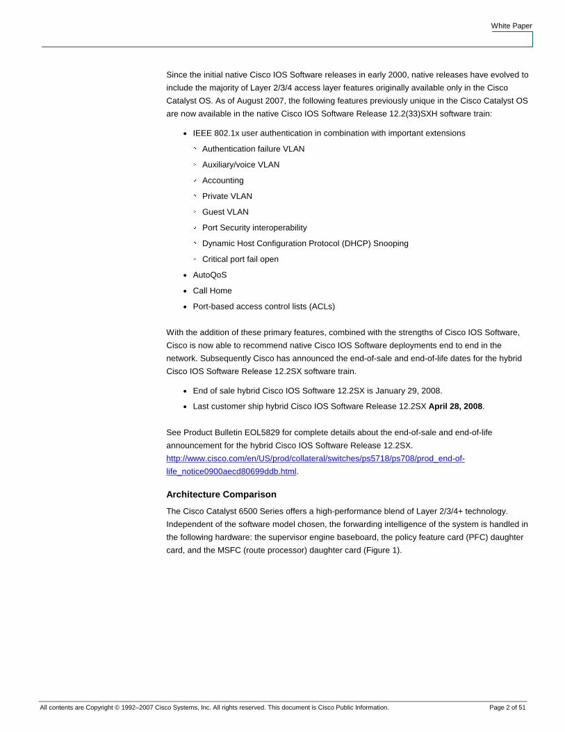
The Cisco Catalyst 6500 Series offers a high-performance blend of Layer 2/3/4+ technology.
Independent of the software model chosen, the forwarding intelligence of the system is handled in
the following hardware: the supervisor engine baseboard, the policy feature card (PFC) daughter
card, and the MSFC (route processor) daughter card (Figure 1).
White Paper
All contents are Copyright © 1992–2007 Cisco Systems, Inc. All rights reserved. This document is Cisco Public Information. Page 3 of 51
Figure 1. Cisco Catalyst 6500 Series Supervisor Engine 720 Components
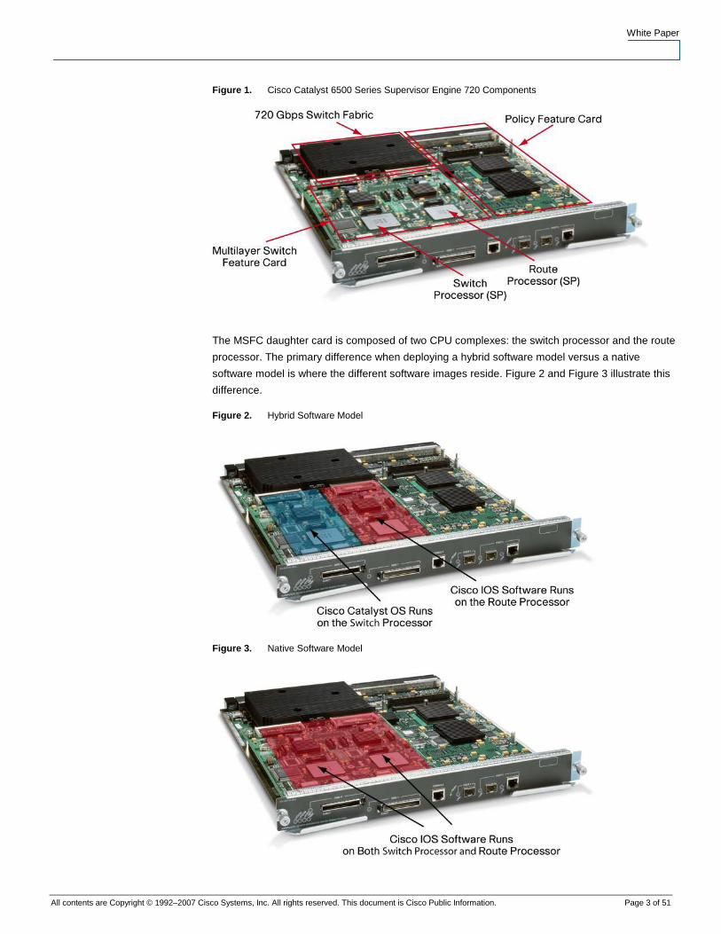
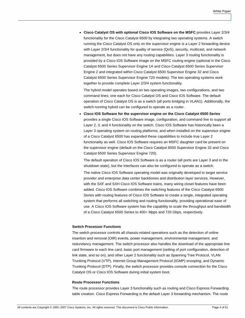
The MSFC daughter card is composed of two CPU complexes: the switch processor and the route
processor. The primary difference when deploying a hybrid software model versus a native
software model is where the different software images reside. Figure 2 and Figure 3 illustrate this
difference.
Figure 2. Hybrid Software Model
Figure 3. Native Software Model
White Paper
All contents are Copyright © 1992–2007 Cisco Systems, Inc. All rights reserved. This document is Cisco Public Information. Page 4 of 51
● Cisco Catalyst OS with optional Cisco IOS Software on the MSFC provides Layer 2/3/4
functionality for the Cisco Catalyst 6500 by integrating two operating systems. A switch
running the Cisco Catalyst OS only on the supervisor engine is a Layer 2 forwarding device
with Layer 2/3/4 functionality for quality of service (QoS), security, multicast, and network
management, but does not have any routing capabilities. Layer 3 routing functionality is
provided by a Cisco IOS Software image on the MSFC routing engine (optional in the Cisco
Catalyst 6500 Series Supervisor Engine 1A and Cisco Catalyst 6500 Series Supervisor
Engine 2 and integrated within Cisco Catalyst 6500 Supervisor Engine 32 and Cisco
Catalyst 6500 Series Supervisor Engine 720 models). The two operating systems work
together to provide complete Layer 2/3/4 system functionality.
The hybrid model operates based on two operating images, two configurations, and two
command lines; one each for Cisco Catalyst OS and Cisco IOS Software. The default
operation of Cisco Catalyst OS is as a switch (all ports bridging in VLAN1). Additionally, the
switch-running hybrid can be configured to operate as a router.
● Cisco IOS Software for the supervisor engine on the Cisco Catalyst 6500 Series
provides a single Cisco IOS Software image, configuration, and command line to support all
Layer 2, 3, and 4 functionality on the switch. Cisco IOS Software has historically been a
Layer 3 operating system on routing platforms, and when installed on the supervisor engine
of a Cisco Catalyst 6500 has expanded these capabilities to include true Layer 2
functionality as well. Cisco IOS Software requires an MSFC daughter card be present on
the supervisor engine (default on the Cisco Catalyst 6500 Supervisor Engine 32 and Cisco
Catalyst 6500 Series Supervisor Engine 720).
The default operation of Cisco IOS Software is as a router (all ports are Layer 3 and in the
shutdown state), but the interfaces can also be configured to operate as a switch.
The native Cisco IOS Software operating model was originally developed to target service
provider and enterprise data center backbones and distribution layer services. However,
with the SXF and SXH Cisco IOS Software trains, many wiring closet features have been
added. Cisco IOS Software combines the switching features of the Cisco Catalyst 6500
Series with routing features of Cisco IOS Software to create a single, integrated operating
system that performs all switching and routing functionality, providing operational ease of
use. A Cisco IOS Software system has the capability to scale the throughput and bandwidth
of a Cisco Catalyst 6500 Series to 400+ Mpps and 720 Gbps, respectively.
Switch Processor Functions
The switch processor controls all chassis-related operations such as the detection of online
insertion and removal (OIR) events, power management, environmental management, and
redundancy management. The switch processor also handles the download of the appropriate line
card firmware to each line card, basic port management (setting of port configuration, detection of
link state, and so on), and other Layer 2 functionality such as Spanning Tree Protocol, VLAN
Trunking Protocol (VTP), Internet Group Management Protocol (IGMP) snooping, and Dynamic
Trunking Protocol (DTP). Finally, the switch processor provides console connection for the Cisco
Catalyst OS or Cisco IOS Software during initial system boot.
Route Processor Functions
The route processor provides Layer 3 functionality such as routing and Cisco Express Forwarding
table creation. Cisco Express Forwarding is the default Layer 3 forwarding mechanism. The route
White Paper
All contents are Copyright © 1992–2007 Cisco Systems, Inc. All rights reserved. This document is Cisco Public Information. Page 5 of 51
processor is responsible for creating and maintaining Cisco Express Forwarding and adjacency
tables while pushing this information down to the PFC for hardware forwarding, QoS, and security
functionality. Other functions residing on the route processor include IP address resolution (ARP)
and routing table maintenance.
Policy Feature Card (PFC)
The PFC is the application-specific integrated circuit (ASIC) forwarding complex for the system.
The PFC performs the hardware-based features and services at a high performance level (tens of
millions of packets per second). Features such as Layer 2 bridging, Layer 3 routing, access
control, QoS marking and policing, NetFlow statistics, and multicast are implemented within the
PFC.
Software Implementation
Native Cisco IOS Software model mandates that both CPUs (switch processor and route
processor) run the full Cisco IOS Software operating system. There is no hidden Cisco Catalyst
software running in the switch, and the executable images used by both CPUs run the complete
Cisco IOS Software kernel. With both processors running Cisco IOS Software, overall system
performance is enhanced.
In contrast, the Cisco Catalyst OS operates on the switch processor and the PFC to provide Layer
2 forwarding and Layer 3/4 services. Should the user require Layer 3 forwarding/routing
capabilities, the MSFC daughter card must be present and runs Cisco IOS Software (as part of the
hybrid OS) on the route processor.
Software Feature Support
The two software models—Cisco Catalyst OS, and Cisco IOS Software—on the Cisco Catalyst
6500 Series are not at complete feature parity. The following table presents the Cisco Catalyst OS
and Cisco IOS Software support for some of the more commonly used protocols. Note that many
features in Cisco IOS Software are not platform specific (for example, the Open Shortest Path First
[OSPF], Border Gateway Protocol [BGP], or Protocol Independent Multicast [PIM] protocols). In
these cases, the Cisco IOS Software features in the hybrid OS are identical to those in Cisco IOS
Software.
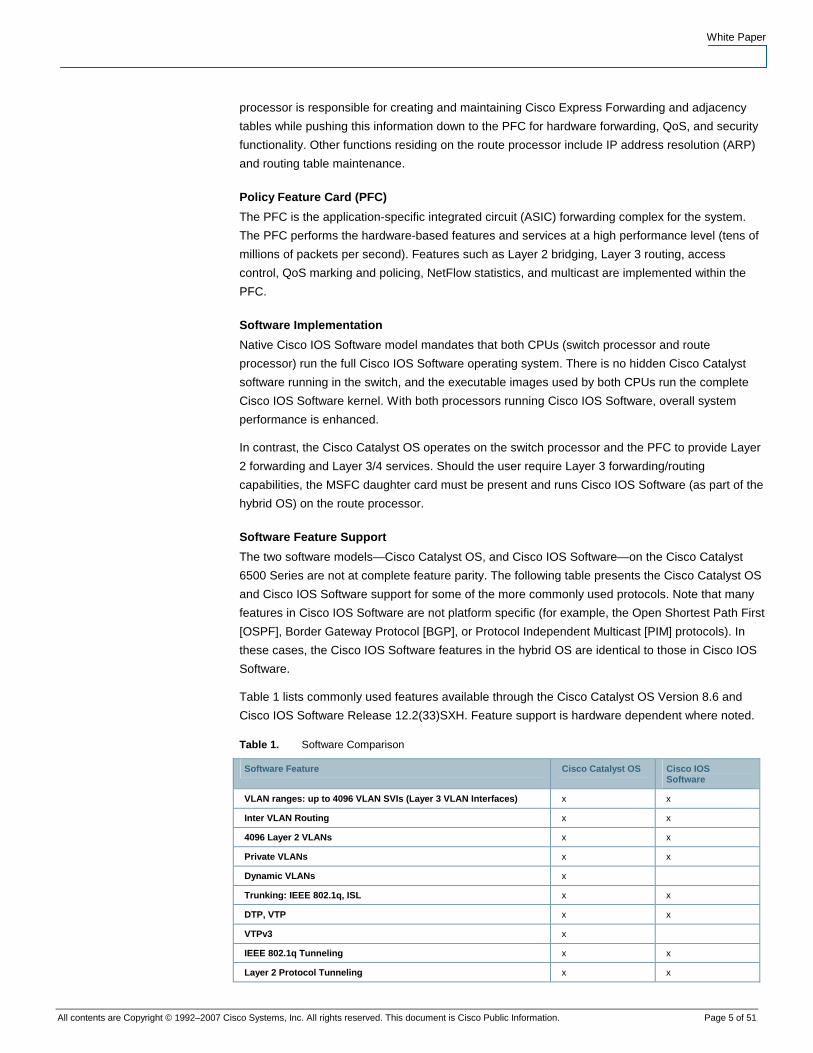
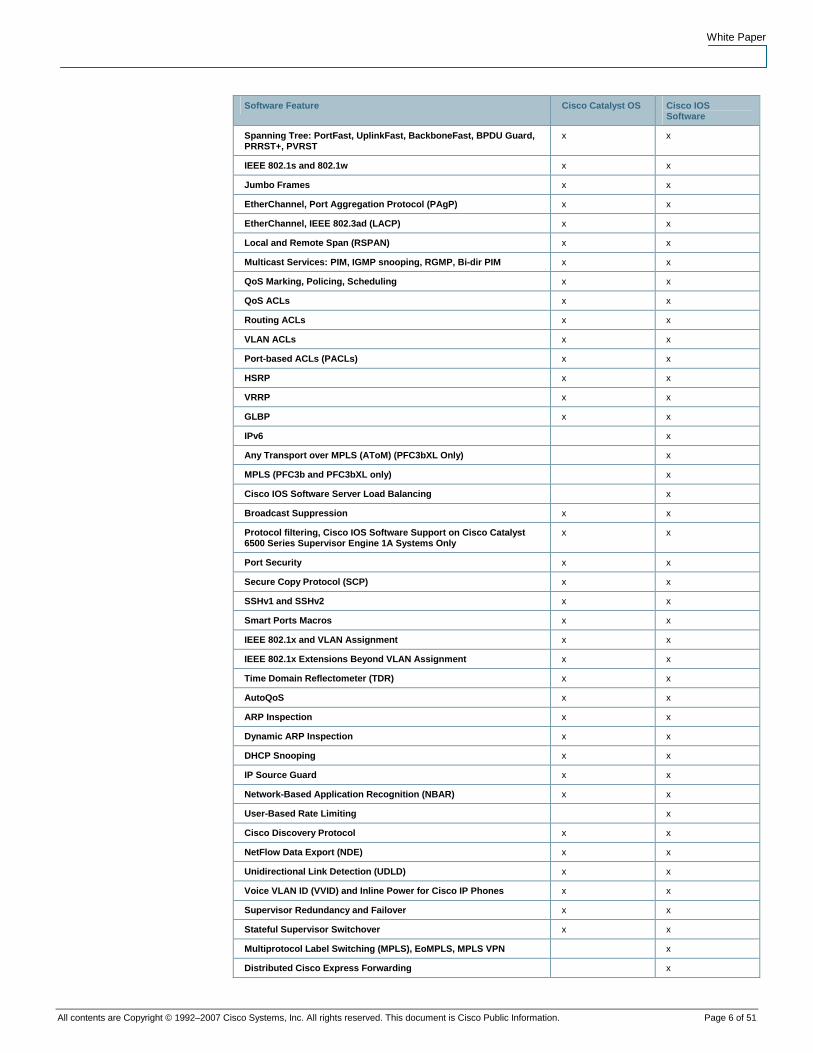
Table 1 lists commonly used features available through the Cisco Catalyst OS Version 8.6 and
Cisco IOS Software Release 12.2(33)SXH. Feature support is hardware dependent where noted.
Table 1. Software Comparison
Software Feature Cisco Catalyst OS Cisco IOS Software
VLAN ranges: up to 4096 VLAN SVIs (Layer 3 VLAN Interfaces) x x
Inter VLAN Routing x x
4096 Layer 2 VLANs x x
Private VLANs x x
Dynamic VLANs x
Trunking: IEEE 802.1q, ISL x x
DTP, VTP x x
VTPv3 x
IEEE 802.1q Tunneling x x
Layer 2 Protocol Tunneling x x
White Paper
All contents are Copyright © 1992–2007 Cisco Systems, Inc. All rights reserved. This document is Cisco Public Information. Page 6 of 51
Software Feature Cisco Catalyst OS Cisco IOS Software
Spanning Tree: PortFast, UplinkFast, BackboneFast, BPDU Guard, PRRST+, PVRST
x x
IEEE 802.1s and 802.1w x x
Jumbo Frames x x
EtherChannel, Port Aggregation Protocol (PAgP) x x
EtherChannel, IEEE 802.3ad (LACP) x x
Local and Remote Span (RSPAN) x x
Multicast Services: PIM, IGMP snooping, RGMP, Bi-dir PIM x x
QoS Marking, Policing, Scheduling x x
QoS ACLs x x
Routing ACLs x x
VLAN ACLs x x
Port-based ACLs (PACLs) x x
HSRP x x
VRRP x x
GLBP x x
IPv6 x
Any Transport over MPLS (AToM) (PFC3bXL Only) x
MPLS (PFC3b and PFC3bXL only) x
Cisco IOS Software Server Load Balancing x
Broadcast Suppression x x
Protocol filtering, Cisco IOS Software Support on Cisco Catalyst 6500 Series Supervisor Engine 1A Systems Only
x x
Port Security x x
Secure Copy Protocol (SCP) x x
SSHv1 and SSHv2 x x
Smart Ports Macros x x
IEEE 802.1x and VLAN Assignment x x
IEEE 802.1x Extensions Beyond VLAN Assignment x x
Time Domain Reflectometer (TDR) x x
AutoQoS x x
ARP Inspection x x
Dynamic ARP Inspection x x
DHCP Snooping x x
IP Source Guard x x
Network-Based Application Recognition (NBAR) x x
User-Based Rate Limiting x
Cisco Discovery Protocol x x
NetFlow Data Export (NDE) x x
Unidirectional Link Detection (UDLD) x x
Voice VLAN ID (VVID) and Inline Power for Cisco IP Phones x x
Supervisor Redundancy and Failover x x
Stateful Supervisor Switchover x x
Multiprotocol Label Switching (MPLS), EoMPLS, MPLS VPN x
Distributed Cisco Express Forwarding x
White Paper
All contents are Copyright © 1992–2007 Cisco Systems, Inc. All rights reserved. This document is Cisco Public Information. Page 7 of 51
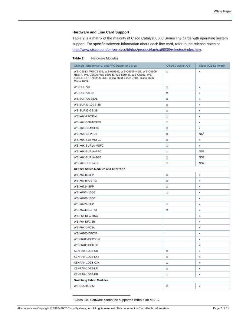
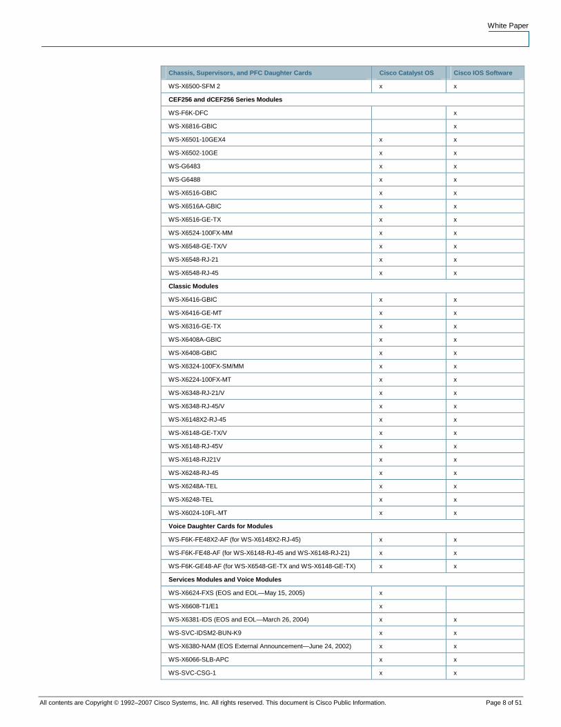
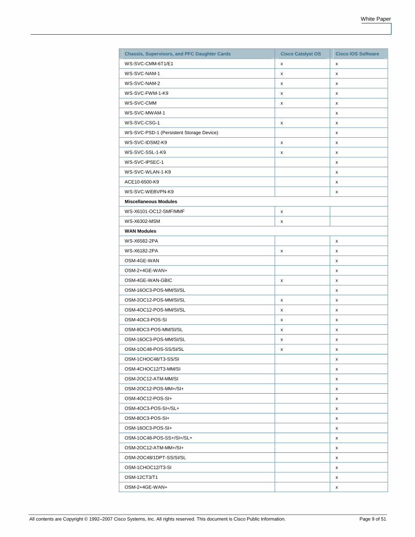
Hardware and Line Card Support
Table 2 is a matrix of the majority of Cisco Catalyst 6500 Series line cards with operating system
support. For specific software information about each line card, refer to the release notes at
http://www.cisco.com/univercd/cc/td/doc/product/lan/cat6000/relnotes/index.htm.
Table 2. Hardware Modules
Chassis, Supervisors, and PFC Daughter Cards Cisco Catalyst OS Cisco IOS Software
WS-C6513, WS-C6509, WS-6509-E, WS-C6509-NEB, WS-C6509-NEB-A, WS-C6506, WS-6506-E, WS-6504-E, WS-C6503, WS-6503-E, OSR-7609-AC/DC, Cisco 7603, Cisco 7604, Cisco 7606, Cisco 7609
x x
WS-SUP720 x x
WS-SUP720-3B x x
WS-SUP720-3BXL x x
WS-SUP32-10GE-3B x x
WS-SUP32-GE-3B x x
WS-X6K-PFC3BXL x x
WS-X6K-S2U-MSFC2 x x
WS-X6K-S2-MSFC2 x x
WS-X6K-S2-PFC2 x NS1
WS-X6K-S1A-MSFC2 x x
WS-X6K-SUP1A-MSFC x x
WS-X6K-SUP1A-PFC x NS2
WS-X6K-SUP1A-2GE x NS2
WS-X6K-SUP1-2GE x NS2
CEF720 Series Modules and XENPAKs
WS-X6748-SFP x x
WS-X6748-GE-TX x x
WS-X6724-SFP x x
WS-X6704-10GE x x
WS-X6708-10GE x
WS-X6724-SFP x x
WS-X6748-GE-TX x x
WS-F6k-DFC 3BXL x
WS-F6k-DFC 3B x
WS-F6K-DFC3A x
WS-X6700-DFC3A x
WS-F6700-DFC3BXL x
WS-F6700-DFC 3B x
XENPAK-10GB-SR x x
XENPAK-10GB-LX4 x x
XENPAK-10GB-CX4 x x
XENPAK-10GB-LR x x
XENPAK-10GB-ER x x
Switching Fabric Modules
WS-C6500-SFM x x
1 Cisco IOS Software cannot be supported without an MSFC.
White Paper
All contents are Copyright © 1992–2007 Cisco Systems, Inc. All rights reserved. This document is Cisco Public Information. Page 8 of 51
Chassis, Supervisors, and PFC Daughter Cards Cisco Catalyst OS Cisco IOS Software
WS-X6500-SFM 2 x x
CEF256 and dCEF256 Series Modules
WS-F6K-DFC x
WS-X6816-GBIC x
WS-X6501-10GEX4 x x
WS-X6502-10GE x x
WS-G6483 x x
WS-G6488 x x
WS-X6516-GBIC x x
WS-X6516A-GBIC x x
WS-X6516-GE-TX x x
WS-X6524-100FX-MM x x
WS-X6548-GE-TX/V x x
WS-X6548-RJ-21 x x
WS-X6548-RJ-45 x x
Classic Modules
WS-X6416-GBIC x x
WS-X6416-GE-MT x x
WS-X6316-GE-TX x x
WS-X6408A-GBIC x x
WS-X6408-GBIC x x
WS-X6324-100FX-SM/MM x x
WS-X6224-100FX-MT x x
WS-X6348-RJ-21/V x x
WS-X6348-RJ-45/V x x
WS-X6148X2-RJ-45 x x
WS-X6148-GE-TX/V x x
WS-X6148-RJ-45V x x
WS-X6148-RJ21V x x
WS-X6248-RJ-45 x x
WS-X6248A-TEL x x
WS-X6248-TEL x x
WS-X6024-10FL-MT x x
Voice Daughter Cards for Modules
WS-F6K-FE48X2-AF (for WS-X6148X2-RJ-45) x x
WS-F6K-FE48-AF (for WS-X6148-RJ-45 and WS-X6148-RJ-21) x x
WS-F6K-GE48-AF (for WS-X6548-GE-TX and WS-X6148-GE-TX) x x
Services Modules and Voice Modules
WS-X6624-FXS (EOS and EOL—May 15, 2005) x
WS-X6608-T1/E1 x
WS-X6381-IDS (EOS and EOL—March 26, 2004) x x
WS-SVC-IDSM2-BUN-K9 x x
WS-X6380-NAM (EOS External Announcement—June 24, 2002) x x
WS-X6066-SLB-APC x x
WS-SVC-CSG-1 x x
White Paper
All contents are Copyright © 1992–2007 Cisco Systems, Inc. All rights reserved. This document is Cisco Public Information. Page 9 of 51
Chassis, Supervisors, and PFC Daughter Cards Cisco Catalyst OS Cisco IOS Software
WS-SVC-CMM-6T1/E1 x x
WS-SVC-NAM-1 x x
WS-SVC-NAM-2 x x
WS-SVC-FWM-1-K9 x x
WS-SVC-CMM x x
WS-SVC-MWAM-1 x
WS-SVC-CSG-1 x x
WS-SVC-PSD-1 (Persistent Storage Device) x
WS-SVC-IDSM2-K9 x x
WS-SVC-SSL-1-K9 x x
WS-SVC-IPSEC-1 x
WS-SVC-WLAN-1-K9 x
ACE10-6500-K9 x
WS-SVC-WEBVPN-K9 x
Miscellaneous Modules
WS-X6101-OC12-SMF/MMF x
WS-X6302-MSM x
WAN Modules
WS-X6582-2PA x
WS-X6182-2PA x x
OSM-4GE-WAN x
OSM-2+4GE-WAN+ x
OSM-4GE-WAN-GBIC x x
OSM-16OC3-POS-MM/SI/SL x
OSM-2OC12-POS-MM/SI/SL x x
OSM-4OC12-POS-MM/SI/SL x x
OSM-4OC3-POS-SI x x
OSM-8OC3-POS-MM/SI/SL x x
OSM-16OC3-POS-MM/SI/SL x x
OSM-1OC48-POS-SS/SI/SL x x
OSM-1CHOC48/T3-SS/SI x
OSM-4CHOC12/T3-MM/SI x
OSM-2OC12-ATM-MM/SI x
OSM-2OC12-POS-MM+/SI+ x
OSM-4OC12-POS-SI+ x
OSM-4OC3-POS-SI+/SL+ x
OSM-8OC3-POS-SI+ x
OSM-16OC3-POS-SI+ x
OSM-1OC48-POS-SS+/SI+/SL+ x
OSM-2OC12-ATM-MM+/SI+ x
OSM-2OC48/1DPT-SS/SI/SL x
OSM-1CHOC12/T3-SI x
OSM-12CT3/T1 x
OSM-2+4GE-WAN+ x
White Paper
All contents are Copyright © 1992–2007 Cisco Systems, Inc. All rights reserved. This document is Cisco Public Information. Page 10 of 51
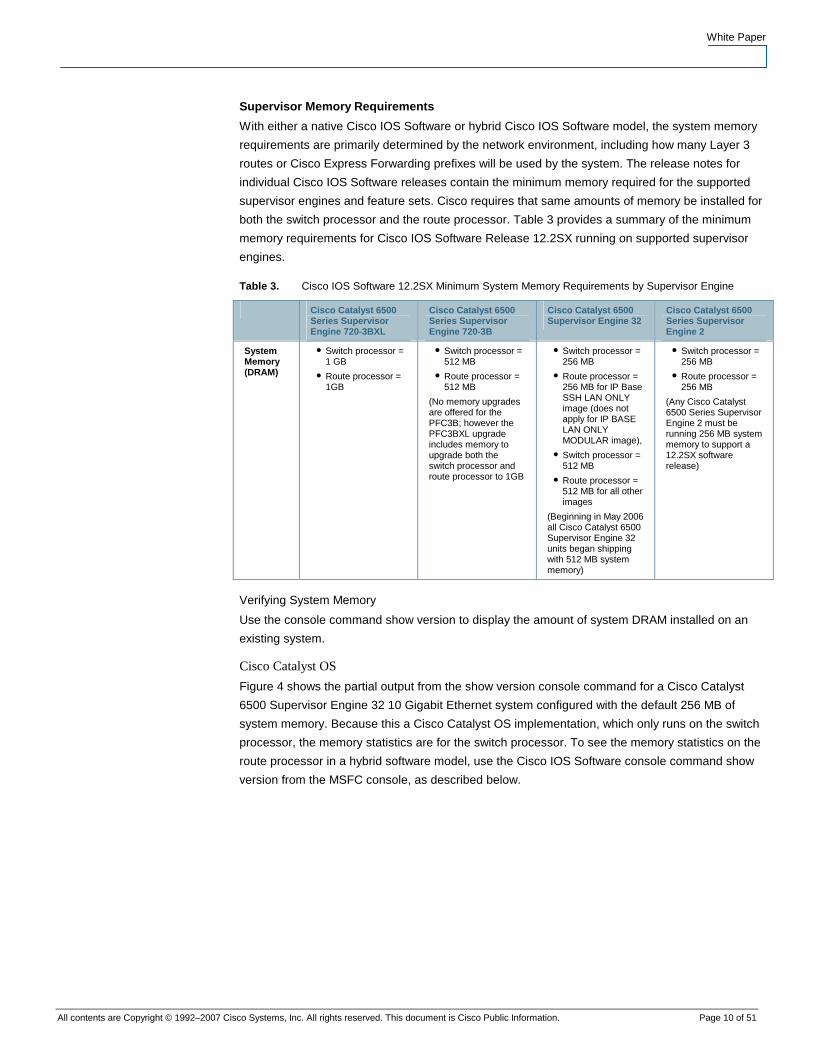
Supervisor Memory Requirements
With either a native Cisco IOS Software or hybrid Cisco IOS Software model, the system memory
requirements are primarily determined by the network environment, including how many Layer 3
routes or Cisco Express Forwarding prefixes will be used by the system. The release notes for
individual Cisco IOS Software releases contain the minimum memory required for the supported
supervisor engines and feature sets. Cisco requires that same amounts of memory be installed for
both the switch processor and the route processor. Table 3 provides a summary of the minimum
memory requirements for Cisco IOS Software Release 12.2SX running on supported supervisor
engines.
Table 3. Cisco IOS Software 12.2SX Minimum System Memory Requirements by Supervisor Engine
Cisco Catalyst 6500 Series Supervisor Engine 720-3BXL
Cisco Catalyst 6500 Series Supervisor Engine 720-3B
Cisco Catalyst 6500 Supervisor Engine 32
Cisco Catalyst 6500 Series Supervisor Engine 2
System Memory (DRAM)
● Switch processor = 1 GB
● Route processor = 1GB
● Switch processor = 512 MB
● Route processor = 512 MB
(No memory upgrades are offered for the PFC3B; however the PFC3BXL upgrade includes memory to upgrade both the switch processor and route processor to 1GB
● Switch processor = 256 MB
● Route processor = 256 MB for IP Base SSH LAN ONLY image (does not apply for IP BASE LAN ONLY MODULAR image),
● Switch processor = 512 MB
● Route processor = 512 MB for all other images
(Beginning in May 2006 all Cisco Catalyst 6500 Supervisor Engine 32 units began shipping with 512 MB system memory)
● Switch processor = 256 MB
● Route processor = 256 MB
(Any Cisco Catalyst 6500 Series Supervisor Engine 2 must be running 256 MB system memory to support a 12.2SX software release)
Verifying System Memory
Use the console command show version to display the amount of system DRAM installed on an
existing system.
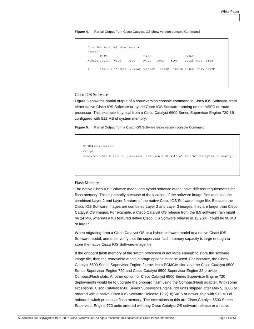
Cisco Catalyst OS
Figure 4 shows the partial output from the show version console command for a Cisco Catalyst
6500 Supervisor Engine 32 10 Gigabit Ethernet system configured with the default 256 MB of
system memory. Because this a Cisco Catalyst OS implementation, which only runs on the switch
processor, the memory statistics are for the switch processor. To see the memory statistics on the
route processor in a hybrid software model, use the Cisco IOS Software console command show
version from the MSFC console, as described below.
White Paper
All contents are Copyright © 1992–2007 Cisco Systems, Inc. All rights reserved. This document is Cisco Public Information. Page 11 of 51
Figure 4. Partial Output from Cisco Catalyst OS show version console Command
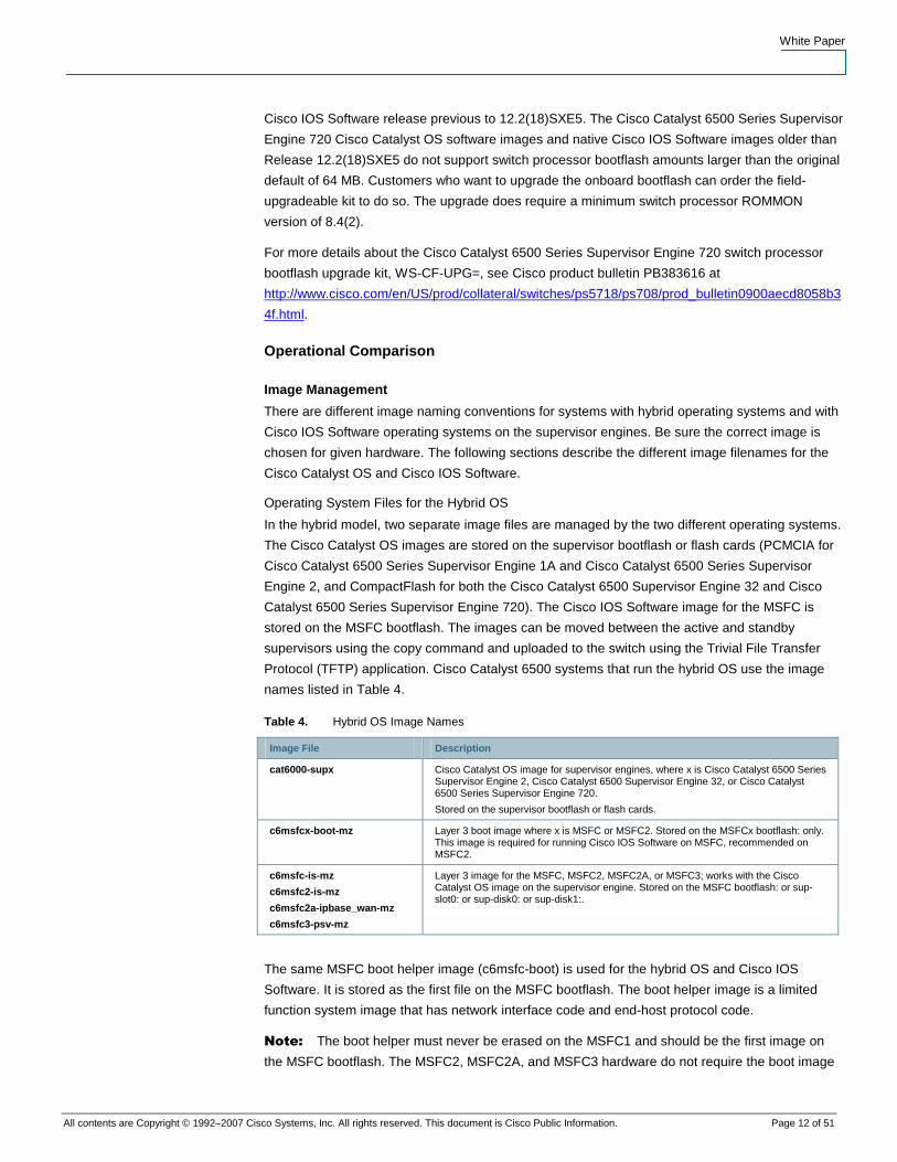
Cisco IOS Software
Figure 5 show the partial output of a show version console command in Cisco IOS Software, from
either native Cisco IOS Software or hybrid Cisco IOS Software running on the MSFC or route
processor. This example is typical from a Cisco Catalyst 6500 Series Supervisor Engine 720-3B
configured with 512 MB of system memory.
Figure 5. Partial Output from a Cisco IOS Software show version console Command
Flash Memory
The native Cisco IOS Software model and hybrid software model have different requirements for
flash memory. This is primarily because of the location of the software image files and also the
combined Layer 2 and Layer 3 nature of the native Cisco IOS Software image file. Because the
Cisco IOS Software images are combined Layer 2 and Layer 3 images, they are larger than Cisco
Catalyst OS images. For example, a Cisco Catalyst OS release from the 8.5 software train might
be 24 MB, whereas a full featured native Cisco IOS Software release in 12.2SXF could be 90 MB
or larger.
When migrating from a Cisco Catalyst OS or a hybrid software model to a native Cisco IOS
Software model, one must verify that the supervisor flash memory capacity is large enough to
store the native Cisco IOS Software image file.
If the onboard flash memory of the switch processor is not large enough to store the software
image file, then the removable media storage options must be used. For instance, the Cisco
Catalyst 6500 Series Supervisor Engine 2 provides a PCMCIA slot, and the Cisco Catalyst 6500
Series Supervisor Engine 720 and Cisco Catalyst 6500 Supervisor Engine 32 provide
CompactFlash slots. Another option for Cisco Catalyst 6500 Series Supervisor Engine 720
deployments would be to upgrade the onboard flash using the CompactFlash adapter. With some
exceptions, Cisco Catalyst 6500 Series Supervisor Engine 720 units shipped after May 5, 2006 or
ordered with a native Cisco IOS Software Release 12.2(18)SXE5 or newer ship with 512 MB of
onboard switch processor flash memory. The exceptions to this are Cisco Catalyst 6500 Series
Supervisor Engine 720 units ordered with any Cisco Catalyst OS software release or a native
White Paper
All contents are Copyright © 1992–2007 Cisco Systems, Inc. All rights reserved. This document is Cisco Public Information. Page 12 of 51
Cisco IOS Software release previous to 12.2(18)SXE5. The Cisco Catalyst 6500 Series Supervisor
Engine 720 Cisco Catalyst OS software images and native Cisco IOS Software images older than
Release 12.2(18)SXE5 do not support switch processor bootflash amounts larger than the original
default of 64 MB. Customers who want to upgrade the onboard bootflash can order the field-
upgradeable kit to do so. The upgrade does require a minimum switch processor ROMMON
version of 8.4(2).
For more details about the Cisco Catalyst 6500 Series Supervisor Engine 720 switch processor
bootflash upgrade kit, WS-CF-UPG=, see Cisco product bulletin PB383616 at
http://www.cisco.com/en/US/prod/collateral/switches/ps5718/ps708/prod_bulletin0900aecd8058b3
4f.html.
Operational Comparison
Image Management
There are different image naming conventions for systems with hybrid operating systems and with
Cisco IOS Software operating systems on the supervisor engines. Be sure the correct image is
chosen for given hardware. The following sections describe the different image filenames for the
Cisco Catalyst OS and Cisco IOS Software.
Operating System Files for the Hybrid OS
In the hybrid model, two separate image files are managed by the two different operating systems.
The Cisco Catalyst OS images are stored on the supervisor bootflash or flash cards (PCMCIA for
Cisco Catalyst 6500 Series Supervisor Engine 1A and Cisco Catalyst 6500 Series Supervisor
Engine 2, and CompactFlash for both the Cisco Catalyst 6500 Supervisor Engine 32 and Cisco
Catalyst 6500 Series Supervisor Engine 720). The Cisco IOS Software image for the MSFC is
stored on the MSFC bootflash. The images can be moved between the active and standby
supervisors using the copy command and uploaded to the switch using the Trivial File Transfer
Protocol (TFTP) application. Cisco Catalyst 6500 systems that run the hybrid OS use the image
names listed in Table 4.
Table 4. Hybrid OS Image Names
Image File Description
cat6000-supx Cisco Catalyst OS image for supervisor engines, where x is Cisco Catalyst 6500 Series Supervisor Engine 2, Cisco Catalyst 6500 Supervisor Engine 32, or Cisco Catalyst 6500 Series Supervisor Engine 720.
Stored on the supervisor bootflash or flash cards.
c6msfcx-boot-mz Layer 3 boot image where x is MSFC or MSFC2. Stored on the MSFCx bootflash: only. This image is required for running Cisco IOS Software on MSFC, recommended on MSFC2.
c6msfc-is-mz
c6msfc2-is-mz
c6msfc2a-ipbase_wan-mz
c6msfc3-psv-mz
Layer 3 image for the MSFC, MSFC2, MSFC2A, or MSFC3; works with the Cisco Catalyst OS image on the supervisor engine. Stored on the MSFC bootflash: or sup-slot0: or sup-disk0: or sup-disk1:.
The same MSFC boot helper image (c6msfc-boot) is used for the hybrid OS and Cisco IOS
Software. It is stored as the first file on the MSFC bootflash. The boot helper image is a limited
function system image that has network interface code and end-host protocol code.
Note: The boot helper must never be erased on the MSFC1 and should be the first image on
the MSFC bootflash. The MSFC2, MSFC2A, and MSFC3 hardware do not require the boot image
White Paper
All contents are Copyright © 1992–2007 Cisco Systems, Inc. All rights reserved. This document is Cisco Public Information. Page 13 of 51
because it has more sophisticated ROMMON2 functionality; however, keeping a boot image in the
MSFC bootflash is still a good practice for in case of emergency. Boot images are not available for
the MSFC2A or MSFC3.
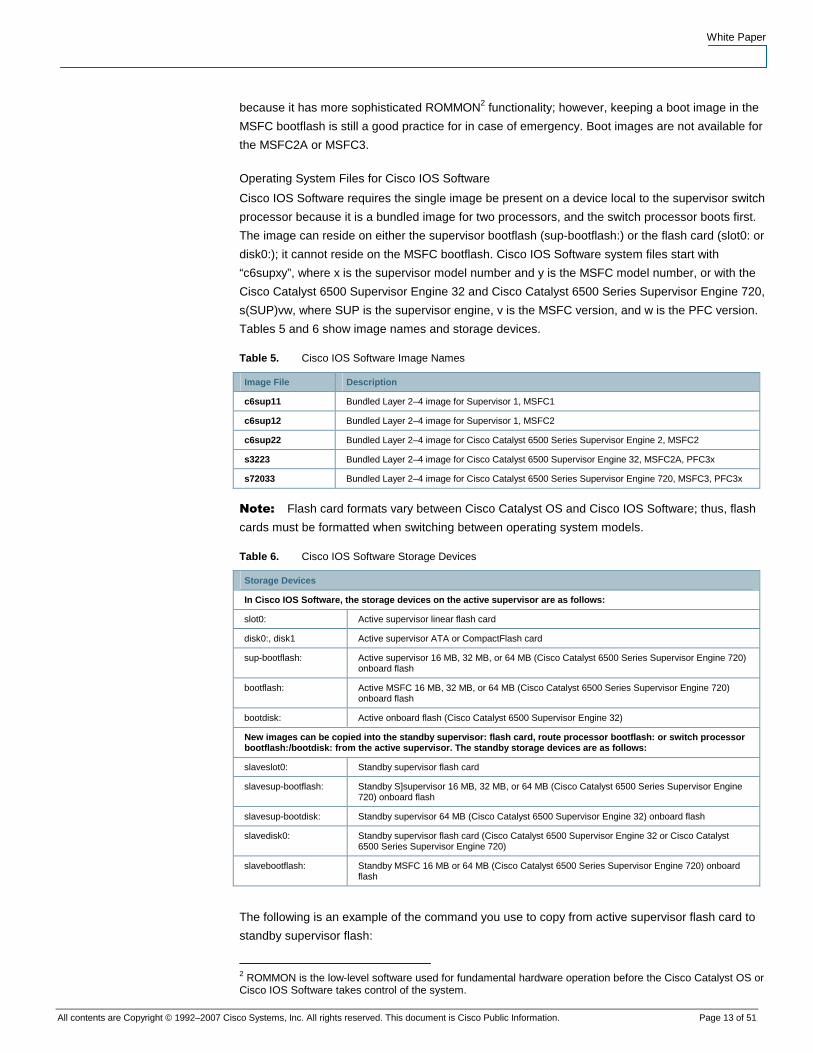
Operating System Files for Cisco IOS Software
Cisco IOS Software requires the single image be present on a device local to the supervisor switch
processor because it is a bundled image for two processors, and the switch processor boots first.
The image can reside on either the supervisor bootflash (sup-bootflash:) or the flash card (slot0: or
disk0:); it cannot reside on the MSFC bootflash. Cisco IOS Software system files start with
“c6supxy”, where x is the supervisor model number and y is the MSFC model number, or with the
Cisco Catalyst 6500 Supervisor Engine 32 and Cisco Catalyst 6500 Series Supervisor Engine 720,
s(SUP)vw, where SUP is the supervisor engine, v is the MSFC version, and w is the PFC version.
Tables 5 and 6 show image names and storage devices.
Table 5. Cisco IOS Software Image Names
Image File Description
c6sup11 Bundled Layer 2–4 image for Supervisor 1, MSFC1
c6sup12 Bundled Layer 2–4 image for Supervisor 1, MSFC2
c6sup22 Bundled Layer 2–4 image for Cisco Catalyst 6500 Series Supervisor Engine 2, MSFC2
s3223 Bundled Layer 2–4 image for Cisco Catalyst 6500 Supervisor Engine 32, MSFC2A, PFC3x
s72033 Bundled Layer 2–4 image for Cisco Catalyst 6500 Series Supervisor Engine 720, MSFC3, PFC3x
Note: Flash card formats vary between Cisco Catalyst OS and Cisco IOS Software; thus, flash
cards must be formatted when switching between operating system models.
Table 6. Cisco IOS Software Storage Devices
Storage Devices
In Cisco IOS Software, the storage devices on the active supervisor are as follows:
slot0: Active supervisor linear flash card
disk0:, disk1 Active supervisor ATA or CompactFlash card
sup-bootflash: Active supervisor 16 MB, 32 MB, or 64 MB (Cisco Catalyst 6500 Series Supervisor Engine 720) onboard flash
bootflash: Active MSFC 16 MB, 32 MB, or 64 MB (Cisco Catalyst 6500 Series Supervisor Engine 720) onboard flash
bootdisk: Active onboard flash (Cisco Catalyst 6500 Supervisor Engine 32)
New images can be copied into the standby supervisor: flash card, route processor bootflash: or switch processor bootflash:/bootdisk: from the active supervisor. The standby storage devices are as follows:
slaveslot0: Standby supervisor flash card
slavesup-bootflash: Standby S]supervisor 16 MB, 32 MB, or 64 MB (Cisco Catalyst 6500 Series Supervisor Engine 720) onboard flash
slavesup-bootdisk: Standby supervisor 64 MB (Cisco Catalyst 6500 Supervisor Engine 32) onboard flash
slavedisk0: Standby supervisor flash card (Cisco Catalyst 6500 Supervisor Engine 32 or Cisco Catalyst 6500 Series Supervisor Engine 720)
slavebootflash: Standby MSFC 16 MB or 64 MB (Cisco Catalyst 6500 Series Supervisor Engine 720) onboard flash
The following is an example of the command you use to copy from active supervisor flash card to
standby supervisor flash:
2 ROMMON is the low-level software used for fundamental hardware operation before the Cisco Catalyst OS or Cisco IOS Software takes control of the system.
White Paper
All contents are Copyright © 1992–2007 Cisco Systems, Inc. All rights reserved. This document is Cisco Public Information. Page 14 of 51
IOS# copy disk0: s72033-jk9sv-mz.122-18.SXD slavesup-disk0:
Destination filename [s72033-jk9sv-mz.122-18.SXD]?
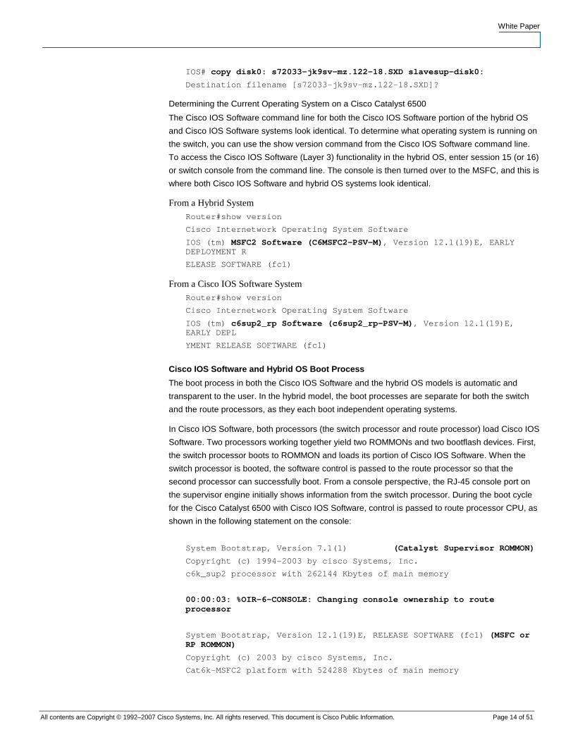
Determining the Current Operating System on a Cisco Catalyst 6500
The Cisco IOS Software command line for both the Cisco IOS Software portion of the hybrid OS
and Cisco IOS Software systems look identical. To determine what operating system is running on
the switch, you can use the show version command from the Cisco IOS Software command line.
To access the Cisco IOS Software (Layer 3) functionality in the hybrid OS, enter session 15 (or 16)
or switch console from the command line. The console is then turned over to the MSFC, and this is
where both Cisco IOS Software and hybrid OS systems look identical.
From a Hybrid System
Router#show version
Cisco Internetwork Operating System Software
IOS (tm) MSFC2 Software (C6MSFC2-PSV-M), Version 12.1(19)E, EARLY DEPLOYMENT R
ELEASE SOFTWARE (fc1)
From a Cisco IOS Software System
Router#show version
Cisco Internetwork Operating System Software
IOS (tm) c6sup2_rp Software (c6sup2_rp-PSV-M), Version 12.1(19)E, EARLY DEPL
YMENT RELEASE SOFTWARE (fc1)
Cisco IOS Software and Hybrid OS Boot Process
The boot process in both the Cisco IOS Software and the hybrid OS models is automatic and
transparent to the user. In the hybrid model, the boot processes are separate for both the switch
and the route processors, as they each boot independent operating systems.
In Cisco IOS Software, both processors (the switch processor and route processor) load Cisco IOS
Software. Two processors working together yield two ROMMONs and two bootflash devices. First,
the switch processor boots to ROMMON and loads its portion of Cisco IOS Software. When the
switch processor is booted, the software control is passed to the route processor so that the
second processor can successfully boot. From a console perspective, the RJ-45 console port on
the supervisor engine initially shows information from the switch processor. During the boot cycle
for the Cisco Catalyst 6500 with Cisco IOS Software, control is passed to route processor CPU, as
shown in the following statement on the console:
System Bootstrap, Version 7.1(1) (Catalyst Supervisor ROMMON)
Copyright (c) 1994-2003 by cisco Systems, Inc.
c6k_sup2 processor with 262144 Kbytes of main memory
00:00:03: %OIR-6-CONSOLE: Changing console ownership to route processor
System Bootstrap, Version 12.1(19)E, RELEASE SOFTWARE (fc1) (MSFC or RP ROMMON)
Copyright (c) 2003 by cisco Systems, Inc.
Cat6k-MSFC2 platform with 524288 Kbytes of main memory
White Paper
All contents are Copyright © 1992–2007 Cisco Systems, Inc. All rights reserved. This document is Cisco Public Information. Page 15 of 51
After this point the route processor controls the system. From the software perspective, the route
processor acts as the primary CPU, and the switch processor acts as the secondary CPU. This is
transparent to the user; all configuration commands are entered directly through the route
processor CPU in Cisco IOS Software. Commands entered that affect the switch processor
functionality are passed internally from the route processor to the switch processor.
Unlike the Cisco Catalyst OS, net booting a Cisco IOS Software image from a TFTP server is not
supported because the supervisor image is a bundled image for two processors. The runtime
image location (c6sup <xy>-is-mz-<version>) must be stored on a device local to the switch
processor (sup-bootflash) or the flash card (slot0:, disk0:, disk1:).
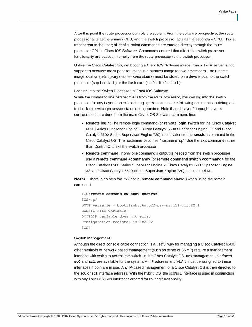
Logging into the Switch Processor in Cisco IOS Software
While the command line perspective is from the route processor, you can log into the switch
processor for any Layer 2-specific debugging. You can use the following commands to debug and
to check the switch processor status during runtime. Note that all Layer 2 through Layer 4
configurations are done from the main Cisco IOS Software command line:
● Remote login: The remote login command (or remote login switch for the Cisco Catalyst
6500 Series Supervisor Engine 2, Cisco Catalyst 6500 Supervisor Engine 32, and Cisco
Catalyst 6500 Series Supervisor Engine 720) is equivalent to the session command in the
Cisco Catalyst OS. The hostname becomes “hostname–sp”. Use the exit command rather
than Control-C to exit the switch processor.
● Remote command: If only one command’s output is needed from the switch processor,
use a remote command <command> (or remote command switch <command> for the
Cisco Catalyst 6500 Series Supervisor Engine 2, Cisco Catalyst 6500 Supervisor Engine
32, and Cisco Catalyst 6500 Series Supervisor Engine 720), as seen below.
Note: There is no help facility (that is, remote command show?) when using the remote
command.
IOS#remote command sw show bootvar
IOS-sp#
BOOT variable = bootflash:c6sup22-psv-mz.121-11b.EX,1
CONFIG_FILE variable =
BOOTLDR variable does not exist
Configuration register is 0x2002
IOS#
Switch Management
Although the direct console cable connection is a useful way for managing a Cisco Catalyst 6500,
other methods of network-based management (such as telnet or SNMP) require a management
interface with which to access the switch. In the Cisco Catalyst OS, two management interfaces,
sc0 and sc1, are available for the system. An IP address and VLAN must be assigned to these
interfaces if both are in use. Any IP-based management of a Cisco Catalyst OS is then directed to
the sc0 or sc1 interface address. With the hybrid OS, the sc0/sc1 interface is used in conjunction
with any Layer 3 VLAN interfaces created for routing functionality.
White Paper
All contents are Copyright © 1992–2007 Cisco Systems, Inc. All rights reserved. This document is Cisco Public Information. Page 16 of 51
CatOS> (enable) show interface
sl0: flags=51<UP,POINTOPOINT,RUNNING>
slip 0.0.0.0 dest 0.0.0.0
sc0: flags=63<UP,BROADCAST,RUNNING>
vlan 1 inet 10.1.1.54 netmask 255.255.255.0 broadcast 10.1.1.255
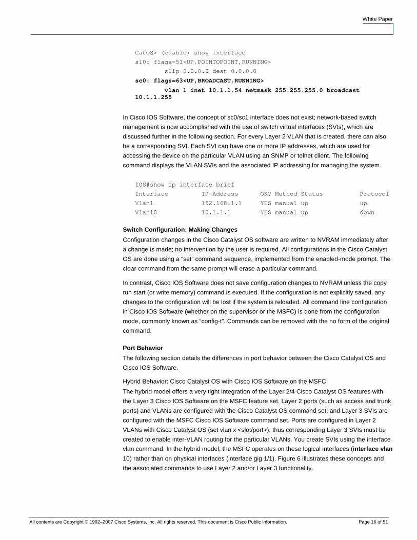
In Cisco IOS Software, the concept of sc0/sc1 interface does not exist; network-based switch
management is now accomplished with the use of switch virtual interfaces (SVIs), which are
discussed further in the following section. For every Layer 2 VLAN that is created, there can also
be a corresponding SVI. Each SVI can have one or more IP addresses, which are used for
accessing the device on the particular VLAN using an SNMP or telnet client. The following
command displays the VLAN SVIs and the associated IP addressing for managing the system.
IOS#show ip interface brief
Interface IP-Address OK? Method Status Protocol
Vlan1 192.168.1.1 YES manual up up
Vlan10 10.1.1.1 YES manual up down
Switch Configuration: Making Changes
Configuration changes in the Cisco Catalyst OS software are written to NVRAM immediately after
a change is made; no intervention by the user is required. All configurations in the Cisco Catalyst
OS are done using a “set” command sequence, implemented from the enabled-mode prompt. The
clear command from the same prompt will erase a particular command.
In contrast, Cisco IOS Software does not save configuration changes to NVRAM unless the copy
run start (or write memory) command is executed. If the configuration is not explicitly saved, any
changes to the configuration will be lost if the system is reloaded. All command line configuration
in Cisco IOS Software (whether on the supervisor or the MSFC) is done from the configuration
mode, commonly known as “config-t”. Commands can be removed with the no form of the original
command.
Port Behavior
The following section details the differences in port behavior between the Cisco Catalyst OS and
Cisco IOS Software.
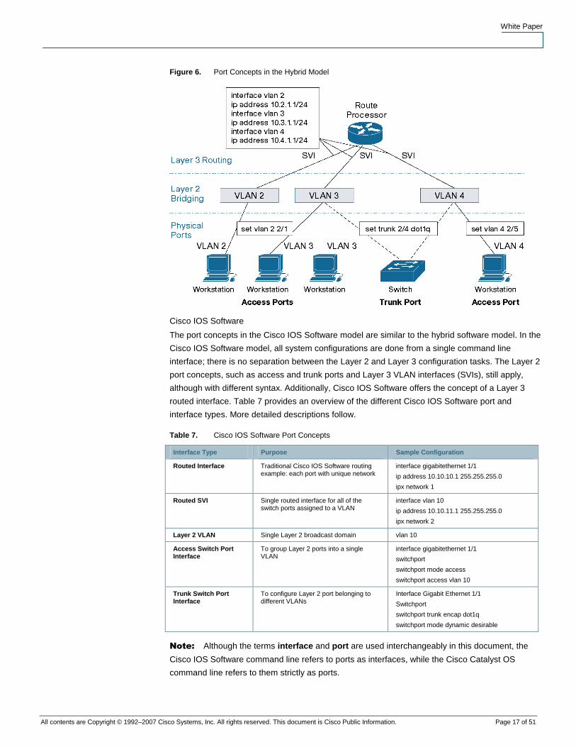
Hybrid Behavior: Cisco Catalyst OS with Cisco IOS Software on the MSFC
The hybrid model offers a very tight integration of the Layer 2/4 Cisco Catalyst OS features with
the Layer 3 Cisco IOS Software on the MSFC feature set. Layer 2 ports (such as access and trunk
ports) and VLANs are configured with the Cisco Catalyst OS command set, and Layer 3 SVIs are
configured with the MSFC Cisco IOS Software command set. Ports are configured in Layer 2
VLANs with Cisco Catalyst OS (set vlan x <slot/port>), thus corresponding Layer 3 SVIs must be
created to enable inter-VLAN routing for the particular VLANs. You create SVIs using the interface
vlan command. In the hybrid model, the MSFC operates on these logical interfaces (interface vlan
10) rather than on physical interfaces (interface gig 1/1). Figure 6 illustrates these concepts and
the associated commands to use Layer 2 and/or Layer 3 functionality.
White Paper
All contents are Copyright © 1992–2007 Cisco Systems, Inc. All rights reserved. This document is Cisco Public Information. Page 17 of 51
Figure 6. Port Concepts in the Hybrid Model
Cisco IOS Software
The port concepts in the Cisco IOS Software model are similar to the hybrid software model. In the
Cisco IOS Software model, all system configurations are done from a single command line
interface; there is no separation between the Layer 2 and Layer 3 configuration tasks. The Layer 2
port concepts, such as access and trunk ports and Layer 3 VLAN interfaces (SVIs), still apply,
although with different syntax. Additionally, Cisco IOS Software offers the concept of a Layer 3
routed interface. Table 7 provides an overview of the different Cisco IOS Software port and
interface types. More detailed descriptions follow.
Table 7. Cisco IOS Software Port Concepts
Interface Type Purpose Sample Configuration
Routed Interface Traditional Cisco IOS Software routing example: each port with unique network
interface gigabitethernet 1/1
ip address 10.10.10.1 255.255.255.0
ipx network 1
Routed SVI Single routed interface for all of the switch ports assigned to a VLAN
interface vlan 10
ip address 10.10.11.1 255.255.255.0
ipx network 2
Layer 2 VLAN Single Layer 2 broadcast domain vlan 10
Access Switch Port Interface
To group Layer 2 ports into a single VLAN
interface gigabitethernet 1/1
switchport
switchport mode access
switchport access vlan 10
Trunk Switch Port Interface
To configure Layer 2 port belonging to different VLANs
Interface Gigabit Ethernet 1/1
Switchport
switchport trunk encap dot1q
switchport mode dynamic desirable
Note: Although the terms interface and port are used interchangeably in this document, the
Cisco IOS Software command line refers to ports as interfaces, while the Cisco Catalyst OS
command line refers to them strictly as ports.
White Paper
All contents are Copyright © 1992–2007 Cisco Systems, Inc. All rights reserved. This document is Cisco Public Information. Page 18 of 51
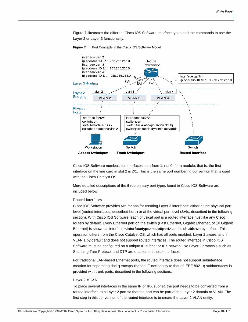
Figure 7 illustrates the different Cisco IOS Software interface types and the commands to use the
Layer 2 or Layer 3 functionality.
Figure 7. Port Concepts in the Cisco IOS Software Model
Cisco IOS Software numbers for interfaces start from 1, not 0, for a module; that is, the first
interface on the line card in slot 2 is 2/1. This is the same port numbering convention that is used
with the Cisco Catalyst OS.
More detailed descriptions of the three primary port types found in Cisco IOS Software are
included below.
Routed Interfaces
Cisco IOS Software provides two means for creating Layer 3 interfaces: either at the physical port
level (routed interfaces, described here) or at the virtual port level (SVIs, described in the following
section). With Cisco IOS Software, each physical port is a routed interface (just like any Cisco
router) by default. Every Ethernet port on the switch (Fast Ethernet, Gigabit Ethernet, or 10 Gigabit
Ethernet) is shown as interface <interfacetype> <slot/port> and is shutdown by default. This
operation differs from the Cisco Catalyst OS, which has all ports enabled, Layer 2 aware, and in
VLAN 1 by default and does not support routed interfaces. The routed interface in Cisco IOS
Software must be configured on a unique IP subnet or IPX network. No Layer 2 protocols such as
Spanning Tree Protocol and DTP are enabled on these interfaces.
For traditional LAN-based Ethernet ports, the routed interface does not support subinterface
creation for separating dot1q encapsulations. Functionality to that of IEEE 802.1q subinterfaces is
provided with trunk ports, described in the following sections.
Layer 2 VLAN
To place several interfaces in the same IP or IPX subnet, the port needs to be converted from a
routed interface to a Layer 2 port so that the port can be part of the Layer 2 domain or VLAN. The
first step in this conversion of the routed interface is to create the Layer 2 VLAN entity.
White Paper
All contents are Copyright © 1992–2007 Cisco Systems, Inc. All rights reserved. This document is Cisco Public Information. Page 19 of 51
The VLAN ID configuration creates an instance of a Layer 2 broadcast domain or VLAN. The
configuration is done from global configuration mode using a vlan <vlan #> command. VLAN IDs
from 1 through 4094 are supported, where VLAN IDs 1002 to 1005 are VTP default VLANs in both
the Cisco Catalyst OS and Cisco IOS Software and are not user configurable.
The following example demonstrates the creation of vlan 8 in the Cisco Catalyst OS and Cisco IOS
Software:
Cisco Catalyst OS Cisco IOS Software
set vlan 8 IOS#configure terminal
IOS(config)#vlan 8
IOS(config-vlan)#exit
Because the Cisco Catalyst OS and Cisco IOS Software support the creation of 4094 Layer 2
VLANs, a MAC-address reduction feature must be enabled so that the system can allocate a
limited number of system MAC addresses more efficiently. The following commands enable this
feature:
Cisco Catalyst OS Cisco IOS Software
set spantree macreduction enable IOS(config)# spanning-tree extend system-id
Routed SVI
When multiple ports on the same device belong to a single subnet, a VLAN is created to group
these ports at Layer 2 (see Layer 2 VLAN, above). Generally, these ports need to send traffic to
other subnets or VLANs. This requirement is accomplished by creating an SVI to provide the inter-
VLAN routing functionality. Just as in the hybrid software model, SVIs in Cisco IOS Software are
identified as interface VLAN 1, interface VLAN 2, and so on. These interfaces are associated
with Layer 3 information such as an IP subnet or IPX network number. If a particular Layer 2 VLAN
does not have an associated SVI created, then traffic will be bridged in that VLAN but is not
routable to or from that VLAN. As switch ports are added to and removed from various VLANs,
they automatically participate in the Layer 3 environment created by the appropriate SVI. For
managing a device in Cisco IOS Software, the SVI requires an IP address for network reachability.
Access Switchport
An access switchport is a Layer 2 port that belongs to only one VLAN. For configuration, the
switchport command is used to convert an interface from the default routed interface to a Layer 2
interface. In converting the port from a Layer 3 port to a Layer 2 port, Layer 2 features, such as
DTP and Spanning Tree Protocol, are enabled. This single switchport command must be
enabled before any other switchport-related configuration is allowed. Like port operation in the
Cisco Catalyst OS, Cisco IOS Software switchports automatically default to VLAN 1. To statically
create an access port (one that will not attempt to negotiate a trunk), enter the switchport mode
access command from the interface configuration. Then use the switchport access vlan <vlan-
id> command to assign the access port to a particular VLAN. The following example defines port
5/1 as an access port in VLAN2:
IOS# configure terminal
IOS(Config)# interface fastethernet5/1
IOS(Config-if)# switchport
IOS(Config-if)# switchport mode access
White Paper
All contents are Copyright © 1992–2007 Cisco Systems, Inc. All rights reserved. This document is Cisco Public Information. Page 20 of 51
IOS(Config-if)# switchport access vlan 2
IOS(Config-if)# no shut
IOS(Config-if)# end
Trunk Switchport
Trunk switchports in Cisco IOS Software are Layer 2 ports that carry multiple VLANs using ISL or
IEEE 802.1q encapsulations. They are fully compatible with any other device supporting the ISL or
IEEE 802.1q protocols.
After converting a routed interface to a Layer 2 switchport, the switchport will default to switchport
mode dynamic desirable. The port is capable of forming a trunk with a neighboring Layer 2 device
by using DTP for negotiating a trunk. If the neighboring interface supports trunking and is
configured to allow trunking, the link becomes a Layer 2 trunk when you enter the switchport
command (because of the dynamic/desirable default). By default, trunks negotiate encapsulation.
If the neighboring interface supports both ISL and IEEE 802.1q encapsulation and both interfaces
are set to negotiate the encapsulation type, the trunk will use ISL encapsulation. This is the same
operation as in the Cisco Catalyst OS. The following example shows how to configure a trunk for
IEEE 802.1q encapsulation:
IOS# configure terminal
IOS(Config)# interface fastethernet 5/1
IOS(Config-if)# switchport
IOS(Config-if)# switchport trunk encapsulation dot1q
IOS(Config-if)# end
For details on the different trunk negotiation states, refer to the Cisco IOS Software Configuration
Guide at http://www.cisco.com/univercd/cc/td/doc/product/lan/cat6000/12_1e/swconfig/layer2.htm.
Note: Recommended configuration for a dynamic trunk port would be desirable/auto between
neighboring devices.
The switchport trunk native vlan <vlan-id> command sets the native VLAN for an IEEE 802.1q
trunk port. The allowed parameter can be used to control the VLANs that are forwarded out that
interface. In addition, the pruning parameter can be used to control VTP pruning on the link.
VLAN1 cannot be pruned, either in the Cisco Catalyst OS or in Cisco IOS Software. However, both
Cisco IOS Software and the Cisco Catalyst OS allow VLAN1 to be disabled from carrying traffic on
trunks.
If a no switchport command is offered, all the commands related to that switchport will no longer
show in configuration and the interface type will revert to a routed interface. However, if the
switchport is reenabled, then all the previous switchport-related commands will still be reinstated.3
Cisco IOS Software Interface Configuration: Range Command
All interface types, whether routed interfaces, SVIs, or switchports, can be configured in groups.
This means you can apply configuration parameters to a group of ports at once. The Cisco IOS
Software range command allows you to configure multiple interfaces simultaneously by specifying
interface range and then the range of ports. The ports in the range can be discontinuous across
the same or different line cards. The following is a sample range configuration:
3 This applies to a system that has not been rebooted since doing the “no switchport” command.
White Paper
All contents are Copyright © 1992–2007 Cisco Systems, Inc. All rights reserved. This document is Cisco Public Information. Page 21 of 51
IOS(config)#int range fa3/1—48,gi1/1—2
IOS(config-if)#switchport
IOS(config-if)#switchport mode access
IOS(config-if)#switchport access vlan 2
IOS(config-if)#spanning-tree portfast
IOS(config-if)#no shut
Note: For Cisco IOS Software images before Release 12.2(18)SXE, the space before the dash
is required, up to five comma-separated ranges are supported, and spaces are not required before
or after the comma.
The range command works for Fast Ethernet, Gigabit Ethernet, and 10 Gigabit Ethernet interfaces
as seen above. It also works with VLAN interfaces if the SVIs are created:
IOS(config)#int range vlan2—4
IOS(config-if)# description Floor 1 access VLANs
Interface Range Macros can be used to identify frequently grouped ports. A specific range of
ports is defined in a macro and given a name. After the macro is created, the macro name can be
used to refer to the port grouping rather than explicitly typing in each port. This is useful when
configuration changes frequently apply to the same group of ports (for example, all 10/100 server
ports). This feature is not available in the Cisco Catalyst OS. The following example defines an
interface-range macro named “servers” that corresponds to ports 3/1 through 3/8.
IOS# configure terminal
IOS(config)#define interface-range servers fastethernet 3/1—8
IOS(config)#int range macro servers
IOS(config-if-range)#
To display the macro:
IOS# show running-config | include define
define interface-range servers fastethernet 3/1—8
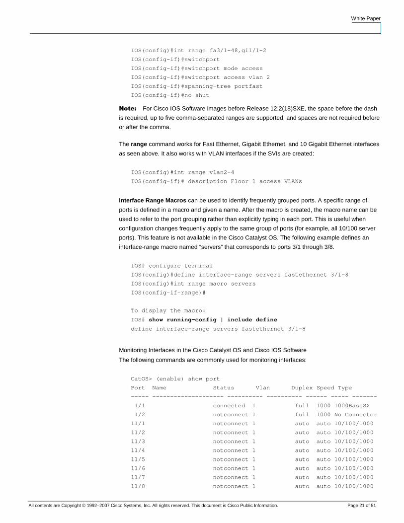
Monitoring Interfaces in the Cisco Catalyst OS and Cisco IOS Software
The following commands are commonly used for monitoring interfaces:
CatOS> (enable) show port
Port Name Status Vlan Duplex Speed Type
----- -------------------- ---------- ---------- ------ ----- -------
1/1 connected 1 full 1000 1000BaseSX
1/2 notconnect 1 full 1000 No Connector
11/1 notconnect 1 auto auto 10/100/1000
11/2 notconnect 1 auto auto 10/100/1000
11/3 notconnect 1 auto auto 10/100/1000
11/4 notconnect 1 auto auto 10/100/1000
11/5 notconnect 1 auto auto 10/100/1000
11/6 notconnect 1 auto auto 10/100/1000
11/7 notconnect 1 auto auto 10/100/1000
11/8 notconnect 1 auto auto 10/100/1000
White Paper
All contents are Copyright © 1992–2007 Cisco Systems, Inc. All rights reserved. This document is Cisco Public Information. Page 22 of 51
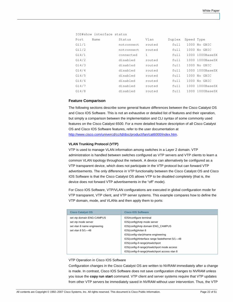
IOS#show interface status
Port Name Status Vlan Duplex Speed Type
Gi1/1 notconnect routed full 1000 No GBIC
Gi1/2 notconnect routed full 1000 No GBIC
Gi4/1 connected 1 full 1000 1000BaseSX
Gi4/2 disabled routed full 1000 1000BaseSX
Gi4/3 disabled routed full 1000 No GBIC
Gi4/4 disabled routed full 1000 1000BaseSX
Gi4/5 disabled routed full 1000 No GBIC
Gi4/6 disabled routed full 1000 No GBIC
Gi4/7 disabled routed full 1000 1000BaseSX
Gi4/8 disabled routed full 1000 1000BaseSX
Feature Comparison
The following sections describe some general feature differences between the Cisco Catalyst OS
and Cisco IOS Software. This is not an exhaustive or detailed list of features and their operation,
but simply a comparison between the implementation and CLI syntax of some commonly used
features on the Cisco Catalyst 6500. For a more detailed feature description of all Cisco Catalyst
OS and Cisco IOS Software features, refer to the user documentation at
http://www.cisco.com/univercd/cc/td/doc/product/lan/cat6000/index.htm.
VLAN Trunking Protocol (VTP)
VTP is used to manage VLAN information among switches in a Layer 2 domain. VTP
administration is handled between switches configured as VTP servers and VTP clients to learn a
common VLAN topology throughout the network. A device can alternatively be configured as a
VTP transparent device, which does not participate in the VTP protocol but can forward VTP
advertisements. The only difference in VTP functionality between the Cisco Catalyst OS and Cisco
IOS Software is that the Cisco Catalyst OS allows VTP to be disabled completely (that is, the
device does not forward VTP advertisements in the “off” mode).
For Cisco IOS Software, VTP/VLAN configurations are executed in global configuration mode for
VTP transparent, VTP client, and VTP server systems. This example compares how to define the
VTP domain, mode, and VLANs and then apply them to ports:
Cisco Catalyst OS Cisco IOS Software
set vtp domain ENG-CAMPUS
set vtp mode server
set vlan 8 name engineering
set vlan 8 5/1—48
IOS#configure terminal
IOS(config)#vtp mode server
IOS(config)#vtp domain ENG_CAMPUS
IOS(config)#vlan 8
IOS(config-vlan)#name engineering
IOS(config)#interface range fastethernet 5/1—48
IOS(config-if-range)#switchport
IOS(config-if-range)#switchport mode access
IOS(config-if-range)#switchport access vlan 8
VTP Operation in Cisco IOS Software
Configuration changes in the Cisco Catalyst OS are written to NVRAM immediately after a change
is made. In contrast, Cisco IOS Software does not save configuration changes to NVRAM unless
you issue the copy run start command. VTP client and server systems require that VTP updates
from other VTP servers be immediately saved in NVRAM without user intervention. Thus, the VTP
White Paper
All contents are Copyright © 1992–2007 Cisco Systems, Inc. All rights reserved. This document is Cisco Public Information. Page 23 of 51
update requirements are met by the default Cisco Catalyst OS operation, whereas the Cisco IOS
Software update model requires an alternative update operation.
For this alteration, a VLAN database was introduced into Cisco IOS Software for the Cisco
Catalyst 6500 as a method for immediately saving VTP updates for VTP clients and servers. This
VLAN database is in the form of a separate file in NVRAM, called the vlan.dat file. Viewed with sh
vtp status, the vlan.dat file stores VTP/VLAN information for VTP client or VTP server systems.
The entire VTP/VLAN configuration is not backed up to the Startup Config file in NVRAM when a
copy run start command is issued on these systems.
This does not apply to systems running as VTP transparent. VTP transparent systems back up the
entire VTP/VLAN configuration to the Startup Config file in NVRAM when you issue a copy run
start command.
VTPv3 for Cisco Catalyst OS
Cisco Catalyst OS supports a new version of VTP, VTP Version 3 (VTPv3). VTPv3 supports the
advertisement of the extended range of VLANs (4094). Configuration changes for the entire 4K
VLAN range can be made centrally on one switch and automatically communicated to all other
switches in the network.
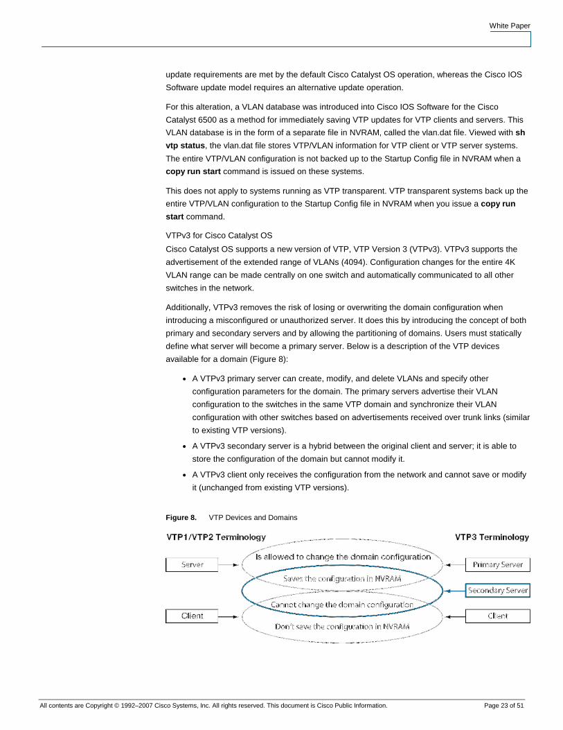
Additionally, VTPv3 removes the risk of losing or overwriting the domain configuration when
introducing a misconfigured or unauthorized server. It does this by introducing the concept of both
primary and secondary servers and by allowing the partitioning of domains. Users must statically
define what server will become a primary server. Below is a description of the VTP devices
available for a domain (Figure 8):
● A VTPv3 primary server can create, modify, and delete VLANs and specify other
configuration parameters for the domain. The primary servers advertise their VLAN
configuration to the switches in the same VTP domain and synchronize their VLAN
configuration with other switches based on advertisements received over trunk links (similar
to existing VTP versions).
● A VTPv3 secondary server is a hybrid between the original client and server; it is able to
store the configuration of the domain but cannot modify it.
● A VTPv3 client only receives the configuration from the network and cannot save or modify
it (unchanged from existing VTP versions).
Figure 8. VTP Devices and Domains
White Paper
All contents are Copyright © 1992–2007 Cisco Systems, Inc. All rights reserved. This document is Cisco Public Information. Page 24 of 51
Spanning Tree Protocol
Spanning Tree Protocol prevents loops from being formed when switches or bridges are
interconnected using multiple paths. Spanning Tree Protocol implements the 802.1D IEEE
algorithm by exchanging BPDU messages with other switches to detect loops and then removes
the loop by shutting down selected bridge interfaces. This algorithm guarantees that there is one
and only one active path between two network devices.
Common Spanning Tree (CST) assumes one spanning-tree instance for the entire bridged
network, regardless of the number of VLANs. This implementation reduces CPU load since only
one Spanning Tree instance is maintained for the entire network. This implementation can be used
when only one Layer 2 topology is needed in the network.
Multiple Instance Spanning Tree Protocol (MISTP) (802.1s) is an IEEE standard that allows
several VLANs to be mapped to a reduced number of spanning-tree instances. This is possible
since most networks do not need more than a few logical topologies. Each instance handles
multiple VLANs that have the same Layer 2 topology.
Per-VLAN Spanning Tree (PVST) maintains a spanning tree instance for each VLAN configured in
the network. It uses ISL Trunking and allows a VLAN trunk to be forwarding for some VLANs while
blocking it for other VLANs. Since PVST treats each VLAN as a separate network, it has the ability
to load balance traffic (at Layer 2) by forwarding some VLANs on one trunk and other VLANs on
another trunk without causing a Spanning Tree Protocol loop. PVST+ (additional advantages are
described later) provides the same functionality with 802.1Q trunking technology and is only
supported on Cisco switches.
Rapid Spanning Tree Protocol (RSTP) is an evolution of Spanning Tree Protocol (802.1D
standard) and provides for faster spanning tree convergence after a topology change. The
standard also includes features equivalent to Cisco PortFast, UplinkFast, and BackboneFast for
faster network reconvergence.
This section presents the configuration differences between the Cisco Catalyst OS and Cisco IOS
Software for basic Spanning Tree Protocol configuration, PVST+ (802.1d), IEEE 802.1s (MST),
IEEE 802.1w (RSTP), and Rapid PVST+.
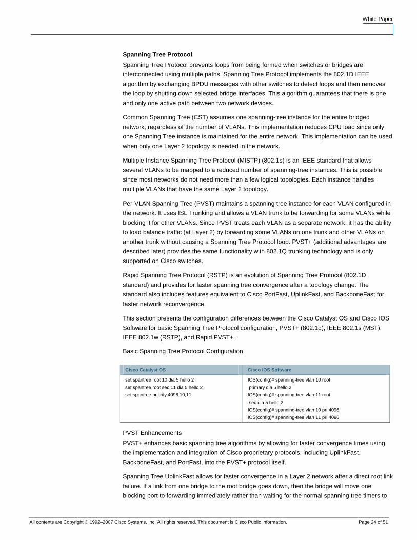
Basic Spanning Tree Protocol Configuration
Cisco Catalyst OS Cisco IOS Software
set spantree root 10 dia 5 hello 2
set spantree root sec 11 dia 5 hello 2
set spantree priority 4096 10,11
IOS(config)# spanning-tree vlan 10 root
primary dia 5 hello 2
IOS(config)# spanning-tree vlan 11 root
sec dia 5 hello 2
IOS(config)# spanning-tree vlan 10 pri 4096
IOS(config)# spanning-tree vlan 11 pri 4096
PVST Enhancements
PVST+ enhances basic spanning tree algorithms by allowing for faster convergence times using
the implementation and integration of Cisco proprietary protocols, including UplinkFast,
BackboneFast, and PortFast, into the PVST+ protocol itself.
Spanning Tree UplinkFast allows for faster convergence in a Layer 2 network after a direct root link
failure. If a link from one bridge to the root bridge goes down, then the bridge will move one
blocking port to forwarding immediately rather than waiting for the normal spanning tree timers to
White Paper
All contents are Copyright © 1992–2007 Cisco Systems, Inc. All rights reserved. This document is Cisco Public Information. Page 25 of 51
expire. This brings the convergence time from 50 seconds to three to five seconds or even
subseconds.
In the case of an indirect failure in a Layer 2 network, Spanning Tree BackboneFast reduces the
convergence time by the “maximum age” timer value (which defaults to 20 seconds).
Finally, Spanning Tree PortFast causes an access port to enter the forwarding state immediately,
bypassing the listening and learning states. The feature is used on switch ports connected to a
single workstation, IP phone, server, and so on and allows these devices to connect to the network
immediately, rather than waiting for spanning tree to converge. Because access ports do not
typically transmit or receive bridge protocol data units (BPDUs) from attached devices, PortFast
mode is supported on both nontrunking access ports and trunk ports in both the Cisco Catalyst OS
and Cisco IOS Software.
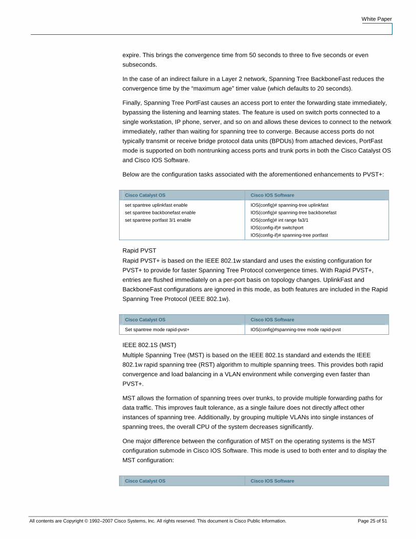
Below are the configuration tasks associated with the aforementioned enhancements to PVST+:
Cisco Catalyst OS Cisco IOS Software
set spantree uplinkfast enable
set spantree backbonefast enable
set spantree portfast 3/1 enable
IOS(config)# spanning-tree uplinkfast
IOS(config)# spanning-tree backbonefast
IOS(config)# int range fa3/1
IOS(config-if)# switchport
IOS(config-if)# spanning-tree portfast
Rapid PVST
Rapid PVST+ is based on the IEEE 802.1w standard and uses the existing configuration for
PVST+ to provide for faster Spanning Tree Protocol convergence times. With Rapid PVST+,
entries are flushed immediately on a per-port basis on topology changes. UplinkFast and
BackboneFast configurations are ignored in this mode, as both features are included in the Rapid
Spanning Tree Protocol (IEEE 802.1w).
Cisco Catalyst OS Cisco IOS Software
Set spantree mode rapid-pvst+ IOS(config)#spanning-tree mode rapid-pvst
IEEE 802.1S (MST)
Multiple Spanning Tree (MST) is based on the IEEE 802.1s standard and extends the IEEE
802.1w rapid spanning tree (RST) algorithm to multiple spanning trees. This provides both rapid
convergence and load balancing in a VLAN environment while converging even faster than
PVST+.
MST allows the formation of spanning trees over trunks, to provide multiple forwarding paths for
data traffic. This improves fault tolerance, as a single failure does not directly affect other
instances of spanning tree. Additionally, by grouping multiple VLANs into single instances of
spanning trees, the overall CPU of the system decreases significantly.
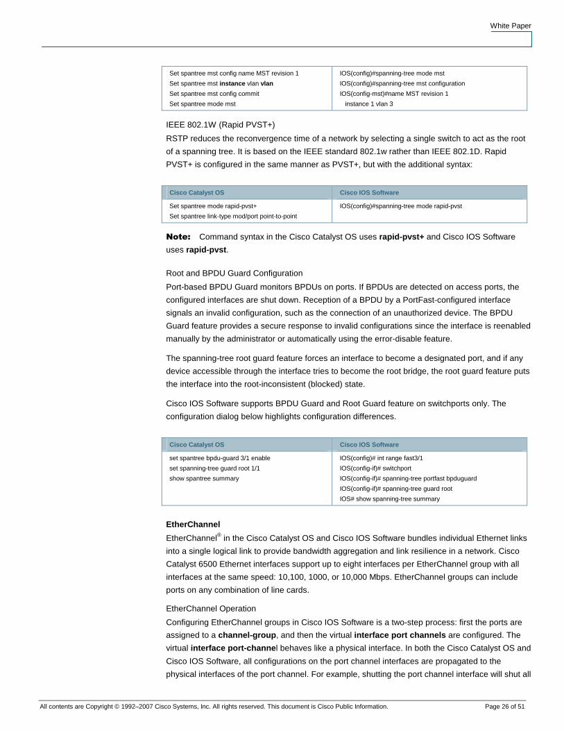
One major difference between the configuration of MST on the operating systems is the MST
configuration submode in Cisco IOS Software. This mode is used to both enter and to display the
MST configuration:
Cisco Catalyst OS Cisco IOS Software
White Paper
All contents are Copyright © 1992–2007 Cisco Systems, Inc. All rights reserved. This document is Cisco Public Information. Page 26 of 51
Set spantree mst config name MST revision 1
Set spantree mst instance vlan vlan
Set spantree mst config commit
Set spantree mode mst
IOS(config)#spanning-tree mode mst
IOS(config)#spanning-tree mst configuration
IOS(config-mst)#name MST revision 1
instance 1 vlan 3
IEEE 802.1W (Rapid PVST+)
RSTP reduces the reconvergence time of a network by selecting a single switch to act as the root
of a spanning tree. It is based on the IEEE standard 802.1w rather than IEEE 802.1D. Rapid
PVST+ is configured in the same manner as PVST+, but with the additional syntax:
Cisco Catalyst OS Cisco IOS Software
Set spantree mode rapid-pvst+
Set spantree link-type mod/port point-to-point
IOS(config)#spanning-tree mode rapid-pvst
Note: Command syntax in the Cisco Catalyst OS uses rapid-pvst+ and Cisco IOS Software
uses rapid-pvst.
Root and BPDU Guard Configuration
Port-based BPDU Guard monitors BPDUs on ports. If BPDUs are detected on access ports, the
configured interfaces are shut down. Reception of a BPDU by a PortFast-configured interface
signals an invalid configuration, such as the connection of an unauthorized device. The BPDU
Guard feature provides a secure response to invalid configurations since the interface is reenabled
manually by the administrator or automatically using the error-disable feature.
The spanning-tree root guard feature forces an interface to become a designated port, and if any
device accessible through the interface tries to become the root bridge, the root guard feature puts
the interface into the root-inconsistent (blocked) state.
Cisco IOS Software supports BPDU Guard and Root Guard feature on switchports only. The
configuration dialog below highlights configuration differences.
Cisco Catalyst OS Cisco IOS Software
set spantree bpdu-guard 3/1 enable
set spanning-tree guard root 1/1
show spantree summary
IOS(config)# int range fast3/1
IOS(config-if)# switchport
IOS(config-if)# spanning-tree portfast bpduguard
IOS(config-if)# spanning-tree guard root
IOS# show spanning-tree summary
EtherChannel
EtherChannel® in the Cisco Catalyst OS and Cisco IOS Software bundles individual Ethernet links
into a single logical link to provide bandwidth aggregation and link resilience in a network. Cisco
Catalyst 6500 Ethernet interfaces support up to eight interfaces per EtherChannel group with all
interfaces at the same speed: 10,100, 1000, or 10,000 Mbps. EtherChannel groups can include
ports on any combination of line cards.
EtherChannel Operation
Configuring EtherChannel groups in Cisco IOS Software is a two-step process: first the ports are
assigned to a channel-group, and then the virtual interface port channels are configured. The
virtual interface port-channel behaves like a physical interface. In both the Cisco Catalyst OS and
Cisco IOS Software, all configurations on the port channel interfaces are propagated to the
physical interfaces of the port channel. For example, shutting the port channel interface will shut all
White Paper
All contents are Copyright © 1992–2007 Cisco Systems, Inc. All rights reserved. This document is Cisco Public Information. Page 27 of 51
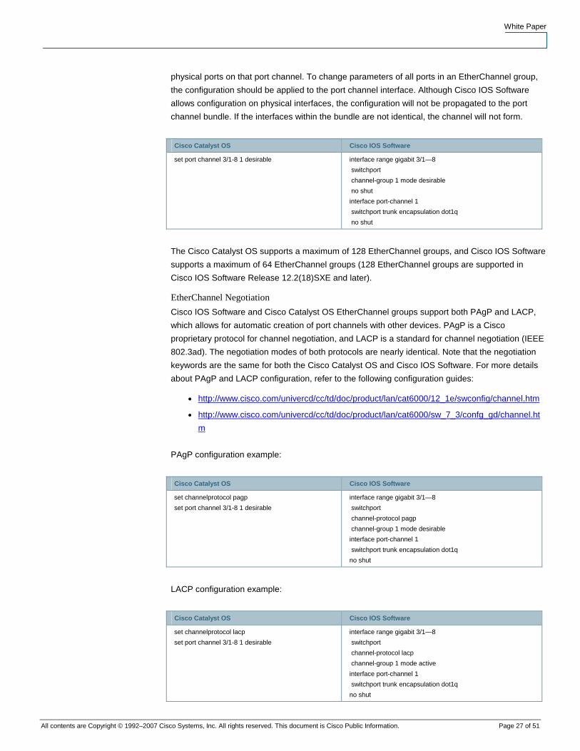
physical ports on that port channel. To change parameters of all ports in an EtherChannel group,
the configuration should be applied to the port channel interface. Although Cisco IOS Software
allows configuration on physical interfaces, the configuration will not be propagated to the port
channel bundle. If the interfaces within the bundle are not identical, the channel will not form.
Cisco Catalyst OS Cisco IOS Software
set port channel 3/1-8 1 desirable interface range gigabit 3/1—8
switchport
channel-group 1 mode desirable
no shut
interface port-channel 1
switchport trunk encapsulation dot1q
no shut
The Cisco Catalyst OS supports a maximum of 128 EtherChannel groups, and Cisco IOS Software
supports a maximum of 64 EtherChannel groups (128 EtherChannel groups are supported in
Cisco IOS Software Release 12.2(18)SXE and later).
EtherChannel Negotiation
Cisco IOS Software and Cisco Catalyst OS EtherChannel groups support both PAgP and LACP,
which allows for automatic creation of port channels with other devices. PAgP is a Cisco
proprietary protocol for channel negotiation, and LACP is a standard for channel negotiation (IEEE
802.3ad). The negotiation modes of both protocols are nearly identical. Note that the negotiation
keywords are the same for both the Cisco Catalyst OS and Cisco IOS Software. For more details
about PAgP and LACP configuration, refer to the following configuration guides:
● http://www.cisco.com/univercd/cc/td/doc/product/lan/cat6000/12_1e/swconfig/channel.htm
● http://www.cisco.com/univercd/cc/td/doc/product/lan/cat6000/sw_7_3/confg_gd/channel.ht
m
PAgP configuration example:
Cisco Catalyst OS Cisco IOS Software
set channelprotocol pagp
set port channel 3/1-8 1 desirable
interface range gigabit 3/1—8
switchport
channel-protocol pagp
channel-group 1 mode desirable
interface port-channel 1
switchport trunk encapsulation dot1q
no shut
LACP configuration example:
Cisco Catalyst OS Cisco IOS Software
set channelprotocol lacp
set port channel 3/1-8 1 desirable
interface range gigabit 3/1—8
switchport
channel-protocol lacp
channel-group 1 mode active
interface port-channel 1
switchport trunk encapsulation dot1q
no shut
White Paper
All contents are Copyright © 1992–2007 Cisco Systems, Inc. All rights reserved. This document is Cisco Public Information. Page 28 of 51
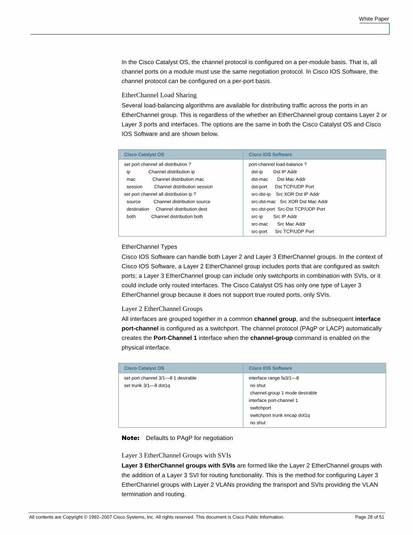
In the Cisco Catalyst OS, the channel protocol is configured on a per-module basis. That is, all
channel ports on a module must use the same negotiation protocol. In Cisco IOS Software, the
channel protocol can be configured on a per-port basis.
EtherChannel Load Sharing
Several load-balancing algorithms are available for distributing traffic across the ports in an
EtherChannel group. This is regardless of the whether an EtherChannel group contains Layer 2 or
Layer 3 ports and interfaces. The options are the same in both the Cisco Catalyst OS and Cisco
IOS Software and are shown below.
Cisco Catalyst OS Cisco IOS Software
set port channel all distribution ?
ip Channel distribution ip
mac Channel distribution mac
session Channel distribution session
set port channel all distribution ip ?
source Channel distribution source
destination Channel distribution dest
both Channel distribution both
port-channel load-balance ?
dst-ip Dst IP Addr
dst-mac Dst Mac Addr
dst-port Dst TCP/UDP Port
src-dst-ip Src XOR Dst IP Addr
src-dst-mac Src XOR Dst Mac Addr
src-dst-port Src-Dst TCP/UDP Port
src-ip Src IP Addr
src-mac Src Mac Addr
src-port Src TCP/UDP Port
EtherChannel Types
Cisco IOS Software can handle both Layer 2 and Layer 3 EtherChannel groups. In the context of
Cisco IOS Software, a Layer 2 EtherChannel group includes ports that are configured as switch
ports; a Layer 3 EtherChannel group can include only switchports in combination with SVIs, or it
could include only routed interfaces. The Cisco Catalyst OS has only one type of Layer 3
EtherChannel group because it does not support true routed ports, only SVIs.
Layer 2 EtherChannel Groups
All interfaces are grouped together in a common channel group, and the subsequent interface
port-channel is configured as a switchport. The channel protocol (PAgP or LACP) automatically
creates the Port-Channel 1 interface when the channel-group command is enabled on the
physical interface.
Cisco Catalyst OS Cisco IOS Software
set port channel 3/1—8 1 desirable
set trunk 3/1—8 dot1q
interface range fa3/1—8
no shut
channel-group 1 mode desirable
interface port-channel 1
switchport
switchport trunk encap dot1q
no shut
Note: Defaults to PAgP for negotiation
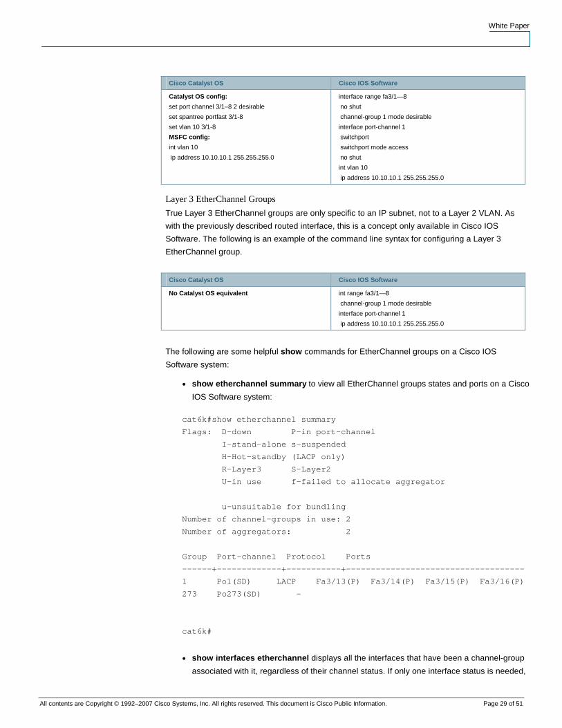
Layer 3 EtherChannel Groups with SVIs
Layer 3 EtherChannel groups with SVIs are formed like the Layer 2 EtherChannel groups with
the addition of a Layer 3 SVI for routing functionality. This is the method for configuring Layer 3
EtherChannel groups with Layer 2 VLANs providing the transport and SVIs providing the VLAN
termination and routing.
White Paper
All contents are Copyright © 1992–2007 Cisco Systems, Inc. All rights reserved. This document is Cisco Public Information. Page 29 of 51
Cisco Catalyst OS Cisco IOS Software
Catalyst OS config:
set port channel 3/1–8 2 desirable
set spantree portfast 3/1-8
set vlan 10 3/1-8
MSFC config:
int vlan 10
ip address 10.10.10.1 255.255.255.0
interface range fa3/1—8
no shut
channel-group 1 mode desirable
interface port-channel 1
switchport
switchport mode access
no shut
int vlan 10
ip address 10.10.10.1 255.255.255.0
Layer 3 EtherChannel Groups
True Layer 3 EtherChannel groups are only specific to an IP subnet, not to a Layer 2 VLAN. As
with the previously described routed interface, this is a concept only available in Cisco IOS
Software. The following is an example of the command line syntax for configuring a Layer 3
EtherChannel group.
Cisco Catalyst OS Cisco IOS Software
No Catalyst OS equivalent int range fa3/1—8
channel-group 1 mode desirable
interface port-channel 1
ip address 10.10.10.1 255.255.255.0
The following are some helpful show commands for EtherChannel groups on a Cisco IOS
Software system:
● show etherchannel summary to view all EtherChannel groups states and ports on a Cisco
IOS Software system:
cat6k#show etherchannel summary
Flags: D—down P—in port-channel
I—stand-alone s—suspended
H—Hot-standby (LACP only)
R—Layer3 S—Layer2
U—in use f—failed to allocate aggregator
u—unsuitable for bundling
Number of channel-groups in use: 2
Number of aggregators: 2
Group Port-channel Protocol Ports
------+-------------+-----------+------------------------------------
1 Po1(SD) LACP Fa3/13(P) Fa3/14(P) Fa3/15(P) Fa3/16(P)
273 Po273(SD) —
cat6k#
● show interfaces etherchannel displays all the interfaces that have been a channel-group
associated with it, regardless of their channel status. If only one interface status is needed,
White Paper
All contents are Copyright © 1992–2007 Cisco Systems, Inc. All rights reserved. This document is Cisco Public Information. Page 30 of 51
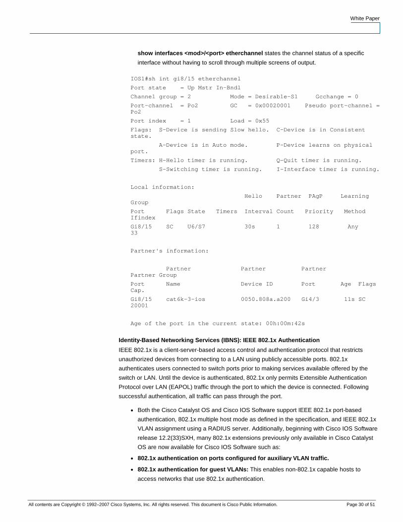
show interfaces <mod>/<port> etherchannel states the channel status of a specific
interface without having to scroll through multiple screens of output.
IOS1#sh int gi8/15 etherchannel
Port state = Up Mstr In-Bndl
Channel group = 2 Mode = Desirable-Sl Gcchange = 0
Port-channel = Po2 GC = 0x00020001 Pseudo port-channel = Po2
Port index = 1 Load = 0x55
Flags: S—Device is sending Slow hello. C—Device is in Consistent state.
A—Device is in Auto mode. P—Device learns on physical port.
Timers: H—Hello timer is running. Q—Quit timer is running.
S—Switching timer is running. I—Interface timer is running.
Local information:
Hello Partner PAgP Learning Group
Port Flags State Timers Interval Count Priority Method Ifindex
Gi8/15 SC U6/S7 30s 1 128 Any 33
Partner's information:
Partner Partner Partner Partner Group
Port Name Device ID Port Age Flags Cap.
Gi8/15 cat6k-3-ios 0050.808a.a200 Gi4/3 11s SC 20001
Age of the port in the current state: 00h:00m:42s
Identity-Based Networking Services (IBNS): IEEE 802.1x Authentication
IEEE 802.1x is a client-server-based access control and authentication protocol that restricts
unauthorized devices from connecting to a LAN using publicly accessible ports. 802.1x
authenticates users connected to switch ports prior to making services available offered by the
switch or LAN. Until the device is authenticated, 802.1x only permits Extensible Authentication
Protocol over LAN (EAPOL) traffic through the port to which the device is connected. Following
successful authentication, all traffic can pass through the port.
● Both the Cisco Catalyst OS and Cisco IOS Software support IEEE 802.1x port-based
authentication, 802.1x multiple host mode as defined in the specification, and IEEE 802.1x
VLAN assignment using a RADIUS server. Additionally, beginning with Cisco IOS Software
release 12.2(33)SXH, many 802.1x extensions previously only available in Cisco Catalyst
OS are now available for Cisco IOS Software such as:
● 802.1x authentication on ports configured for auxiliary VLAN traffic.
● 802.1x authentication for guest VLANs: This enables non-802.1x capable hosts to
access networks that use 802.1x authentication.
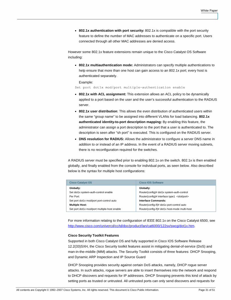
White Paper
All contents are Copyright © 1992–2007 Cisco Systems, Inc. All rights reserved. This document is Cisco Public Information. Page 31 of 51
● 802.1x authentication with port security: 802.1x is compatible with the port security
feature to define the number of MAC addresses to authenticate on a specific port. Users
connected through all other MAC addresses are denied access.
However some 802.1x feature extensions remain unique to the Cisco Catalyst OS Software
including:
● 802.1x multiauthentication mode: Administrators can specify multiple authentications to
help ensure that more than one host can gain access to an 802.1x port; every host is
authenticated separately.
Example: Set port dot1x mod/port multiple-authentication enable
● 802.1x with ACL assignment: This extension allows an ACL policy to be dynamically
applied to a port based on the user and the user’s successful authentication to the RADIUS
server.
● 802.1x user distribution: This allows the even distribution of authenticated users within
the same “group name” to be assigned into different VLANs for load balancing. 802.1x
authenticated identity-to-port description mapping: By enabling this feature, the
administrator can assign a port description to the port that a user is authenticated to. The
description is seen after “sh port” is executed. This is configured on the RADIUS server.
● DNS resolution for RADIUS: Allows the administrator to configure a server DNS name in
addition to or instead of an IP address. In the event of a RADIUS server moving subnets,
there is no reconfiguration required for the switches.
A RADIUS server must be specified prior to enabling 802.1x on the switch. 802.1x is then enabled
globally, and finally enabled from the console for individual ports, as seen below. Also described
below is the syntax for multiple host configurations:
Cisco Catalyst OS Cisco IOS Software
Globally:
Set dot1x system-auth-control enable
Per Port:
Set port dot1x mod/port port-control auto
Multiple Host:
Set port dot1x mod/port multiple-host enable
Globally:
Router(config)# dot1x system-auth-control
Router(config)# interface type1 <slot/port>
Interface Commands:
Router(config-if)# dot1x port-control auto
Router(config-if)# dot1x host-mode multi-host
For more information relating to the configuration of IEEE 802.1x on the Cisco Catalyst 6500, see
http://www.cisco.com/univercd/cc/td/doc/product/lan/cat6000/122sx/swcg/dot1x.htm.
Cisco Security Toolkit Features
Supported in both Cisco Catalyst OS and fully supported in Cisco IOS Software Release
12.2(33)SXH, the Cisco Security toolkit features assist in mitigating denial-of-service (DoS) and
man-in-the-middle (MiM) attacks. The Security Toolkit consists of three features: DHCP Snooping,
and Dynamic ARP Inspection and IP Source Guard
DHCP Snooping provides security against certain DoS attacks, namely, DHCP rogue server
attacks. In such attacks, rogue servers are able to insert themselves into the network and respond
to DHCP discovers and requests for IP addresses. DHCP Snooping prevents this kind of attack by
setting ports as trusted or untrusted. All untrusted ports can only send discovers and requests for
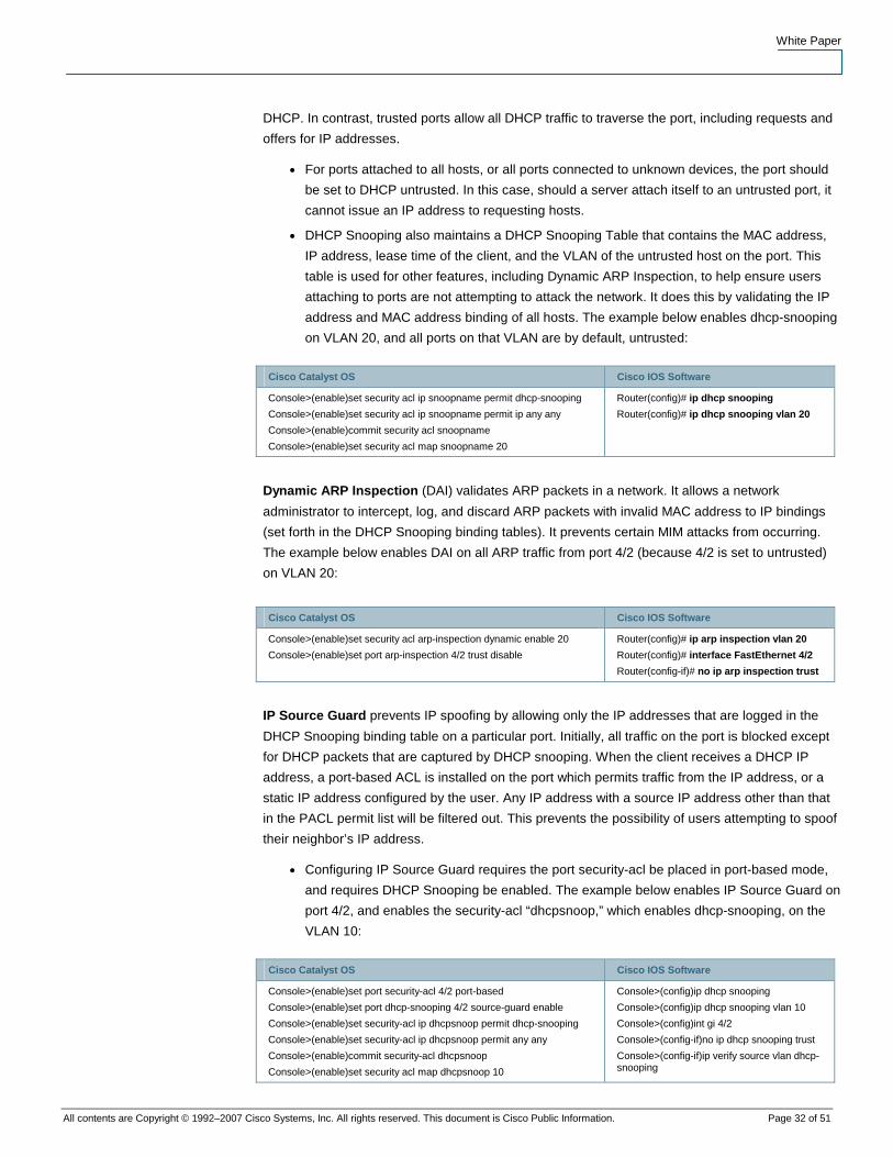
White Paper
All contents are Copyright © 1992–2007 Cisco Systems, Inc. All rights reserved. This document is Cisco Public Information. Page 32 of 51
DHCP. In contrast, trusted ports allow all DHCP traffic to traverse the port, including requests and
offers for IP addresses.
● For ports attached to all hosts, or all ports connected to unknown devices, the port should
be set to DHCP untrusted. In this case, should a server attach itself to an untrusted port, it
cannot issue an IP address to requesting hosts.
● DHCP Snooping also maintains a DHCP Snooping Table that contains the MAC address,
IP address, lease time of the client, and the VLAN of the untrusted host on the port. This
table is used for other features, including Dynamic ARP Inspection, to help ensure users
attaching to ports are not attempting to attack the network. It does this by validating the IP
address and MAC address binding of all hosts. The example below enables dhcp-snooping
on VLAN 20, and all ports on that VLAN are by default, untrusted:
Cisco Catalyst OS Cisco IOS Software
Console>(enable)set security acl ip snoopname permit dhcp-snooping
Console>(enable)set security acl ip snoopname permit ip any any
Console>(enable)commit security acl snoopname
Console>(enable)set security acl map snoopname 20
Router(config)# ip dhcp snooping
Router(config)# ip dhcp snooping vlan 20
Dynamic ARP Inspection (DAI) validates ARP packets in a network. It allows a network
administrator to intercept, log, and discard ARP packets with invalid MAC address to IP bindings
(set forth in the DHCP Snooping binding tables). It prevents certain MIM attacks from occurring.
The example below enables DAI on all ARP traffic from port 4/2 (because 4/2 is set to untrusted)
on VLAN 20:
Cisco Catalyst OS Cisco IOS Software
Console>(enable)set security acl arp-inspection dynamic enable 20
Console>(enable)set port arp-inspection 4/2 trust disable
Router(config)# ip arp inspection vlan 20
Router(config)# interface FastEthernet 4/2
Router(config-if)# no ip arp inspection trust
IP Source Guard prevents IP spoofing by allowing only the IP addresses that are logged in the
DHCP Snooping binding table on a particular port. Initially, all traffic on the port is blocked except
for DHCP packets that are captured by DHCP snooping. When the client receives a DHCP IP
address, a port-based ACL is installed on the port which permits traffic from the IP address, or a
static IP address configured by the user. Any IP address with a source IP address other than that
in the PACL permit list will be filtered out. This prevents the possibility of users attempting to spoof
their neighbor’s IP address.
● Configuring IP Source Guard requires the port security-acl be placed in port-based mode,
and requires DHCP Snooping be enabled. The example below enables IP Source Guard on
port 4/2, and enables the security-acl “dhcpsnoop,” which enables dhcp-snooping, on the
VLAN 10:
Cisco Catalyst OS Cisco IOS Software
Console>(enable)set port security-acl 4/2 port-based
Console>(enable)set port dhcp-snooping 4/2 source-guard enable
Console>(enable)set security-acl ip dhcpsnoop permit dhcp-snooping
Console>(enable)set security-acl ip dhcpsnoop permit any any
Console>(enable)commit security-acl dhcpsnoop
Console>(enable)set security acl map dhcpsnoop 10
Console>(config)ip dhcp snooping
Console>(config)ip dhcp snooping vlan 10
Console>(config)int gi 4/2
Console>(config-if)no ip dhcp snooping trust
Console>(config-if)ip verify source vlan dhcp-snooping
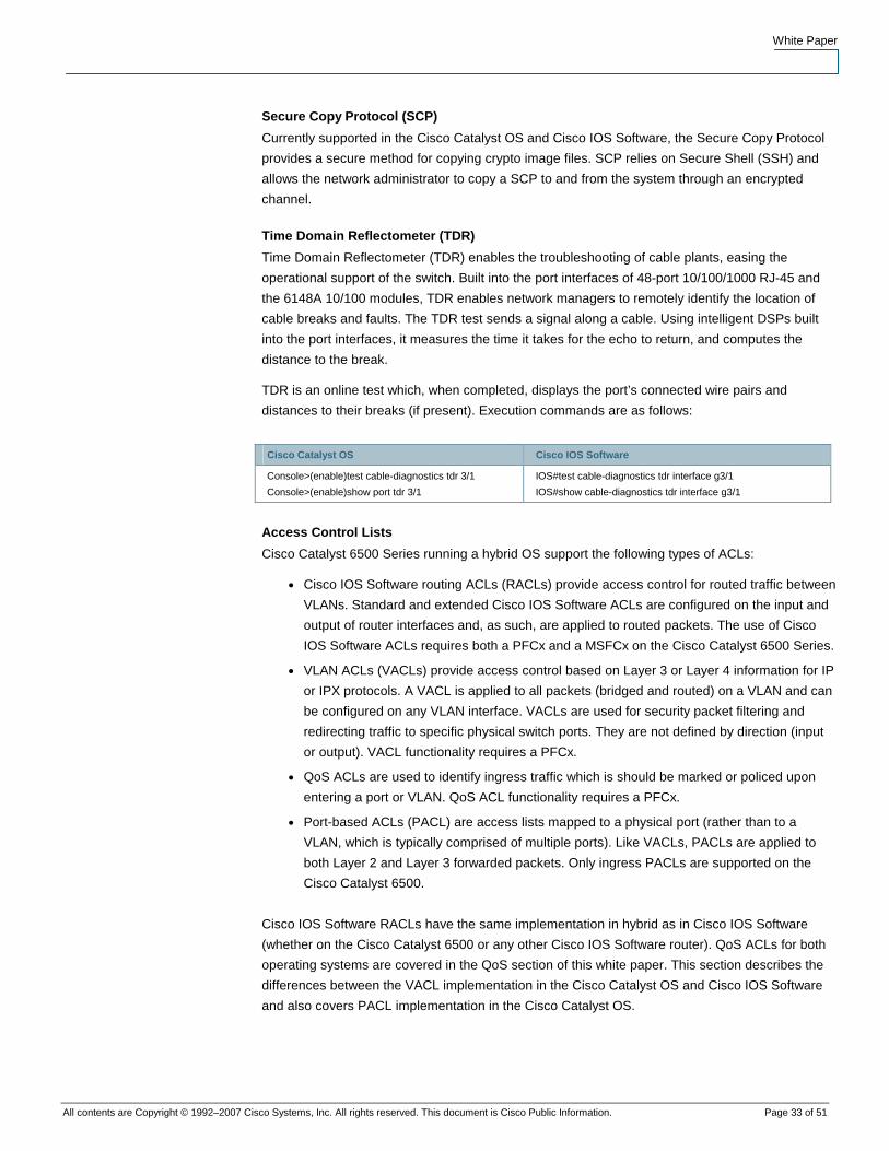
White Paper
All contents are Copyright © 1992–2007 Cisco Systems, Inc. All rights reserved. This document is Cisco Public Information. Page 33 of 51
Secure Copy Protocol (SCP)
Currently supported in the Cisco Catalyst OS and Cisco IOS Software, the Secure Copy Protocol
provides a secure method for copying crypto image files. SCP relies on Secure Shell (SSH) and
allows the network administrator to copy a SCP to and from the system through an encrypted
channel.
Time Domain Reflectometer (TDR)
Time Domain Reflectometer (TDR) enables the troubleshooting of cable plants, easing the
operational support of the switch. Built into the port interfaces of 48-port 10/100/1000 RJ-45 and
the 6148A 10/100 modules, TDR enables network managers to remotely identify the location of
cable breaks and faults. The TDR test sends a signal along a cable. Using intelligent DSPs built
into the port interfaces, it measures the time it takes for the echo to return, and computes the
distance to the break.
TDR is an online test which, when completed, displays the port’s connected wire pairs and
distances to their breaks (if present). Execution commands are as follows:
Cisco Catalyst OS Cisco IOS Software
Console>(enable)test cable-diagnostics tdr 3/1
Console>(enable)show port tdr 3/1
IOS#test cable-diagnostics tdr interface g3/1
IOS#show cable-diagnostics tdr interface g3/1
Access Control Lists
Cisco Catalyst 6500 Series running a hybrid OS support the following types of ACLs:
● Cisco IOS Software routing ACLs (RACLs) provide access control for routed traffic between
VLANs. Standard and extended Cisco IOS Software ACLs are configured on the input and
output of router interfaces and, as such, are applied to routed packets. The use of Cisco
IOS Software ACLs requires both a PFCx and a MSFCx on the Cisco Catalyst 6500 Series.
● VLAN ACLs (VACLs) provide access control based on Layer 3 or Layer 4 information for IP
or IPX protocols. A VACL is applied to all packets (bridged and routed) on a VLAN and can
be configured on any VLAN interface. VACLs are used for security packet filtering and
redirecting traffic to specific physical switch ports. They are not defined by direction (input
or output). VACL functionality requires a PFCx.
● QoS ACLs are used to identify ingress traffic which is should be marked or policed upon
entering a port or VLAN. QoS ACL functionality requires a PFCx.
● Port-based ACLs (PACL) are access lists mapped to a physical port (rather than to a
VLAN, which is typically comprised of multiple ports). Like VACLs, PACLs are applied to
both Layer 2 and Layer 3 forwarded packets. Only ingress PACLs are supported on the
Cisco Catalyst 6500.
Cisco IOS Software RACLs have the same implementation in hybrid as in Cisco IOS Software
(whether on the Cisco Catalyst 6500 or any other Cisco IOS Software router). QoS ACLs for both
operating systems are covered in the QoS section of this white paper. This section describes the
differences between the VACL implementation in the Cisco Catalyst OS and Cisco IOS Software
and also covers PACL implementation in the Cisco Catalyst OS.
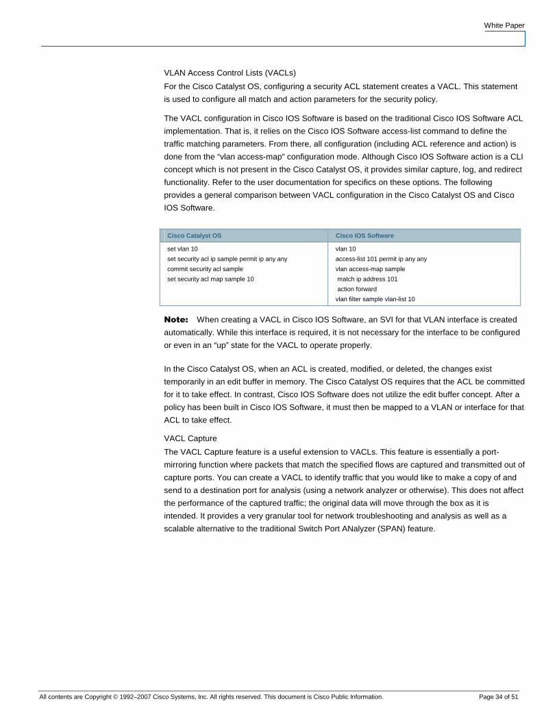
White Paper
All contents are Copyright © 1992–2007 Cisco Systems, Inc. All rights reserved. This document is Cisco Public Information. Page 34 of 51
VLAN Access Control Lists (VACLs)
For the Cisco Catalyst OS, configuring a security ACL statement creates a VACL. This statement
is used to configure all match and action parameters for the security policy.
The VACL configuration in Cisco IOS Software is based on the traditional Cisco IOS Software ACL
implementation. That is, it relies on the Cisco IOS Software access-list command to define the
traffic matching parameters. From there, all configuration (including ACL reference and action) is
done from the “vlan access-map” configuration mode. Although Cisco IOS Software action is a CLI
concept which is not present in the Cisco Catalyst OS, it provides similar capture, log, and redirect
functionality. Refer to the user documentation for specifics on these options. The following
provides a general comparison between VACL configuration in the Cisco Catalyst OS and Cisco
IOS Software.
Cisco Catalyst OS Cisco IOS Software
set vlan 10
set security acl ip sample permit ip any any
commit security acl sample
set security acl map sample 10
vlan 10
access-list 101 permit ip any any
vlan access-map sample
match ip address 101
action forward
vlan filter sample vlan-list 10
Note: When creating a VACL in Cisco IOS Software, an SVI for that VLAN interface is created
automatically. While this interface is required, it is not necessary for the interface to be configured
or even in an “up” state for the VACL to operate properly.
In the Cisco Catalyst OS, when an ACL is created, modified, or deleted, the changes exist
temporarily in an edit buffer in memory. The Cisco Catalyst OS requires that the ACL be committed
for it to take effect. In contrast, Cisco IOS Software does not utilize the edit buffer concept. After a
policy has been built in Cisco IOS Software, it must then be mapped to a VLAN or interface for that
ACL to take effect.
VACL Capture
The VACL Capture feature is a useful extension to VACLs. This feature is essentially a port-
mirroring function where packets that match the specified flows are captured and transmitted out of
capture ports. You can create a VACL to identify traffic that you would like to make a copy of and
send to a destination port for analysis (using a network analyzer or otherwise). This does not affect
the performance of the captured traffic; the original data will move through the box as it is
intended. It provides a very granular tool for network troubleshooting and analysis as well as a
scalable alternative to the traditional Switch Port ANalyzer (SPAN) feature.
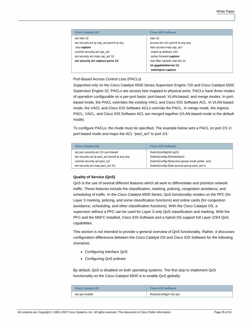
White Paper
All contents are Copyright © 1992–2007 Cisco Systems, Inc. All rights reserved. This document is Cisco Public Information. Page 35 of 51
Cisco Catalyst OS Cisco IOS Software
set vlan 10
set security acl ip cap_acl permit ip any
any capture
commit security acl cap_acl
set security acl map cap_acl 10
set security acl capture-ports 1/1
vlan 10
access-list 101 permit ip any any
vlan access-map cap_acl
match ip address 101
action forward capture
vlan filter sample vlan-list 10
int gigabitethernet 1/1
switchport capture
Port-Based Access Control Lists (PACLs)
Supported only on the Cisco Catalyst 6500 Series Supervisor Engine 720 and Cisco Catalyst 6500
Supervisor Engine 32, PACLs are access lists mapped to physical ports. PACLs have three modes
of operation configurable on a per-port basis: port-based, VLAN-based, and merge modes. In port-
based mode, the PACL overrides the existing VACL and Cisco IOS Software ACL. In VLAN-based
mode, the VACL and Cisco IOS Software ACLs override the PACL. In merge mode, the ingress
PACL, VACL, and Cisco IOS Software ACL are merged together (VLAN-based mode is the default
mode).
To configure PACLs, the mode must be specified. The example below sets a PACL on port 2/1 in
port-based mode and maps the ACL “pacl_acl” to port 2/1:
Cisco Catalyst OS Cisco IOS Software
set port security-acl 2/1 port-based
set security acl ip pacl_acl permit ip any any
commit security acl pacl_acl
set security acl map pacl_acl 2/1
Switch(config)#int gi2/1
Switch(config-if)#switchport
Switch(config-if)#access-group mode prefer port
Switch(config-if)#ip access-group pacl_acl in
Quality of Service (QoS)
QoS is the use of several different features which all work to differentiate and prioritize network
traffic. These features include the classification, marking, policing, congestion avoidance, and
scheduling of traffic. In the Cisco Catalyst 6500 Series, QoS functionality resides on the PFC (for
Layer 3 marking, policing, and some classification functions) and online cards (for congestion
avoidance, scheduling, and other classification functions). With the Cisco Catalyst OS, a
supervisor without a PFC can be used for Layer 2-only QoS classification and marking. With the
PFC and the MSFC installed, Cisco IOS Software and a hybrid OS support full Layer 2/3/4 QoS
capabilities.
This section is not intended to provide a general overview of QoS functionality. Rather, it discusses
configuration differences between the Cisco Catalyst OS and Cisco IOS Software for the following
scenarios:
● Configuring interface QoS
● Configuring QoS policies
By default, QoS is disabled on both operating systems. The first step to implement QoS
functionality on the Cisco Catalyst 6500 is to enable QoS globally:
Cisco Catalyst OS Cisco IOS Software
set qos enable Router(config)# mls qos
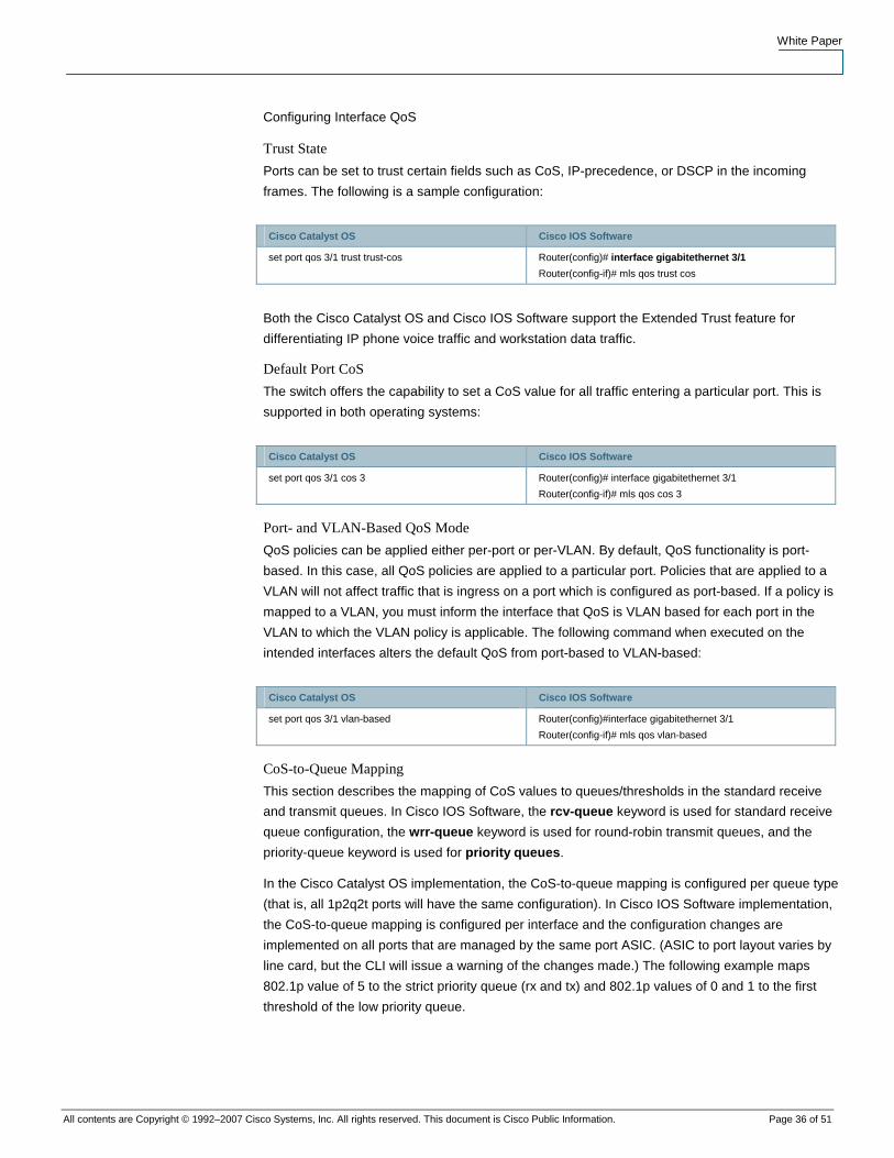
White Paper
All contents are Copyright © 1992–2007 Cisco Systems, Inc. All rights reserved. This document is Cisco Public Information. Page 36 of 51
Configuring Interface QoS
Trust State
Ports can be set to trust certain fields such as CoS, IP-precedence, or DSCP in the incoming
frames. The following is a sample configuration:
Cisco Catalyst OS Cisco IOS Software
set port qos 3/1 trust trust-cos Router(config)# interface gigabitethernet 3/1
Router(config-if)# mls qos trust cos
Both the Cisco Catalyst OS and Cisco IOS Software support the Extended Trust feature for
differentiating IP phone voice traffic and workstation data traffic.
Default Port CoS
The switch offers the capability to set a CoS value for all traffic entering a particular port. This is
supported in both operating systems:
Cisco Catalyst OS Cisco IOS Software
set port qos 3/1 cos 3 Router(config)# interface gigabitethernet 3/1
Router(config-if)# mls qos cos 3
Port- and VLAN-Based QoS Mode
QoS policies can be applied either per-port or per-VLAN. By default, QoS functionality is port-
based. In this case, all QoS policies are applied to a particular port. Policies that are applied to a
VLAN will not affect traffic that is ingress on a port which is configured as port-based. If a policy is
mapped to a VLAN, you must inform the interface that QoS is VLAN based for each port in the
VLAN to which the VLAN policy is applicable. The following command when executed on the
intended interfaces alters the default QoS from port-based to VLAN-based:
Cisco Catalyst OS Cisco IOS Software
set port qos 3/1 vlan-based Router(config)#interface gigabitethernet 3/1
Router(config-if)# mls qos vlan-based
CoS-to-Queue Mapping
This section describes the mapping of CoS values to queues/thresholds in the standard receive
and transmit queues. In Cisco IOS Software, the rcv-queue keyword is used for standard receive
queue configuration, the wrr-queue keyword is used for round-robin transmit queues, and the
priority-queue keyword is used for priority queues.
In the Cisco Catalyst OS implementation, the CoS-to-queue mapping is configured per queue type
(that is, all 1p2q2t ports will have the same configuration). In Cisco IOS Software implementation,
the CoS-to-queue mapping is configured per interface and the configuration changes are
implemented on all ports that are managed by the same port ASIC. (ASIC to port layout varies by
line card, but the CLI will issue a warning of the changes made.) The following example maps
802.1p value of 5 to the strict priority queue (rx and tx) and 802.1p values of 0 and 1 to the first
threshold of the low priority queue.
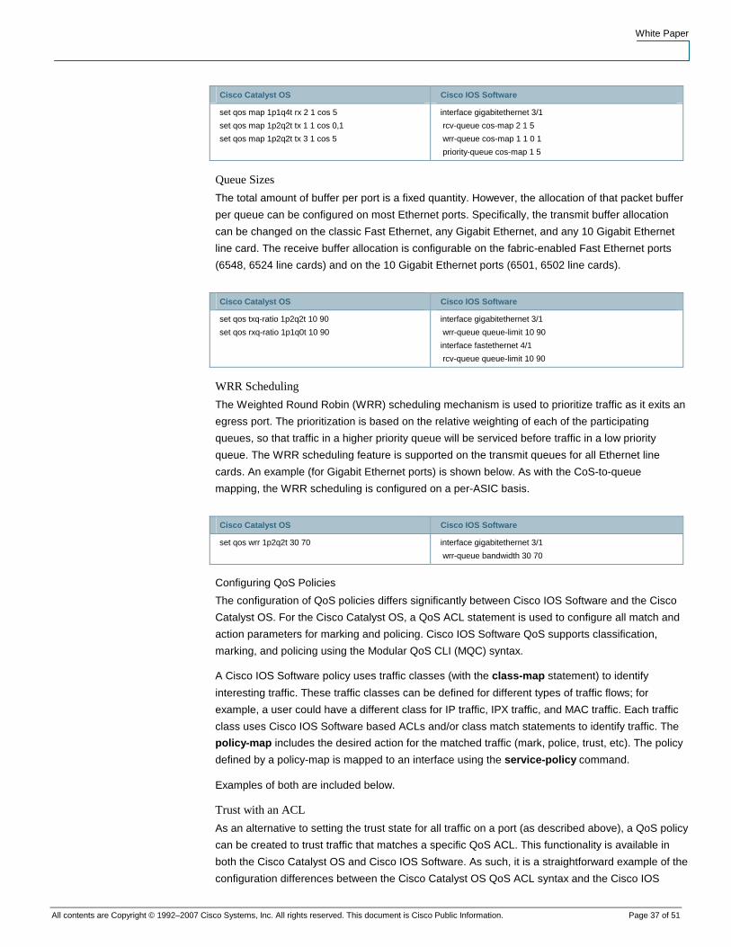
White Paper
All contents are Copyright © 1992–2007 Cisco Systems, Inc. All rights reserved. This document is Cisco Public Information. Page 37 of 51
Cisco Catalyst OS Cisco IOS Software
set qos map 1p1q4t rx 2 1 cos 5
set qos map 1p2q2t tx 1 1 cos 0,1
set qos map 1p2q2t tx 3 1 cos 5
interface gigabitethernet 3/1
rcv-queue cos-map 2 1 5
wrr-queue cos-map 1 1 0 1
priority-queue cos-map 1 5
Queue Sizes
The total amount of buffer per port is a fixed quantity. However, the allocation of that packet buffer
per queue can be configured on most Ethernet ports. Specifically, the transmit buffer allocation
can be changed on the classic Fast Ethernet, any Gigabit Ethernet, and any 10 Gigabit Ethernet
line card. The receive buffer allocation is configurable on the fabric-enabled Fast Ethernet ports
(6548, 6524 line cards) and on the 10 Gigabit Ethernet ports (6501, 6502 line cards).
Cisco Catalyst OS Cisco IOS Software
set qos txq-ratio 1p2q2t 10 90
set qos rxq-ratio 1p1q0t 10 90
interface gigabitethernet 3/1
wrr-queue queue-limit 10 90
interface fastethernet 4/1
rcv-queue queue-limit 10 90
WRR Scheduling
The Weighted Round Robin (WRR) scheduling mechanism is used to prioritize traffic as it exits an
egress port. The prioritization is based on the relative weighting of each of the participating
queues, so that traffic in a higher priority queue will be serviced before traffic in a low priority
queue. The WRR scheduling feature is supported on the transmit queues for all Ethernet line
cards. An example (for Gigabit Ethernet ports) is shown below. As with the CoS-to-queue
mapping, the WRR scheduling is configured on a per-ASIC basis.
Cisco Catalyst OS Cisco IOS Software
set qos wrr 1p2q2t 30 70 interface gigabitethernet 3/1
wrr-queue bandwidth 30 70
Configuring QoS Policies
The configuration of QoS policies differs significantly between Cisco IOS Software and the Cisco
Catalyst OS. For the Cisco Catalyst OS, a QoS ACL statement is used to configure all match and
action parameters for marking and policing. Cisco IOS Software QoS supports classification,
marking, and policing using the Modular QoS CLI (MQC) syntax.
A Cisco IOS Software policy uses traffic classes (with the class-map statement) to identify
interesting traffic. These traffic classes can be defined for different types of traffic flows; for
example, a user could have a different class for IP traffic, IPX traffic, and MAC traffic. Each traffic
class uses Cisco IOS Software based ACLs and/or class match statements to identify traffic. The
policy-map includes the desired action for the matched traffic (mark, police, trust, etc). The policy
defined by a policy-map is mapped to an interface using the service-policy command.
Examples of both are included below.
Trust with an ACL
As an alternative to setting the trust state for all traffic on a port (as described above), a QoS policy
can be created to trust traffic that matches a specific QoS ACL. This functionality is available in
both the Cisco Catalyst OS and Cisco IOS Software. As such, it is a straightforward example of the
configuration differences between the Cisco Catalyst OS QoS ACL syntax and the Cisco IOS
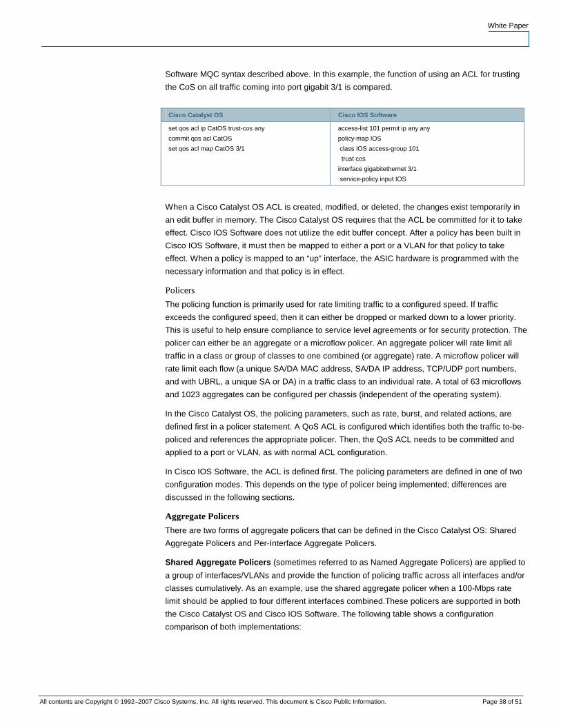
White Paper
All contents are Copyright © 1992–2007 Cisco Systems, Inc. All rights reserved. This document is Cisco Public Information. Page 38 of 51
Software MQC syntax described above. In this example, the function of using an ACL for trusting
the CoS on all traffic coming into port gigabit 3/1 is compared.
Cisco Catalyst OS Cisco IOS Software
set qos acl ip CatOS trust-cos any
commit qos acl CatOS
set qos acl map CatOS 3/1
access-list 101 permit ip any any
policy-map IOS
class IOS access-group 101
trust cos
interface gigabitethernet 3/1
service-policy input IOS
When a Cisco Catalyst OS ACL is created, modified, or deleted, the changes exist temporarily in
an edit buffer in memory. The Cisco Catalyst OS requires that the ACL be committed for it to take
effect. Cisco IOS Software does not utilize the edit buffer concept. After a policy has been built in
Cisco IOS Software, it must then be mapped to either a port or a VLAN for that policy to take
effect. When a policy is mapped to an “up” interface, the ASIC hardware is programmed with the
necessary information and that policy is in effect.
Policers
The policing function is primarily used for rate limiting traffic to a configured speed. If traffic
exceeds the configured speed, then it can either be dropped or marked down to a lower priority.
This is useful to help ensure compliance to service level agreements or for security protection. The
policer can either be an aggregate or a microflow policer. An aggregate policer will rate limit all
traffic in a class or group of classes to one combined (or aggregate) rate. A microflow policer will
rate limit each flow (a unique SA/DA MAC address, SA/DA IP address, TCP/UDP port numbers,
and with UBRL, a unique SA or DA) in a traffic class to an individual rate. A total of 63 microflows
and 1023 aggregates can be configured per chassis (independent of the operating system).
In the Cisco Catalyst OS, the policing parameters, such as rate, burst, and related actions, are
defined first in a policer statement. A QoS ACL is configured which identifies both the traffic to-be-
policed and references the appropriate policer. Then, the QoS ACL needs to be committed and
applied to a port or VLAN, as with normal ACL configuration.
In Cisco IOS Software, the ACL is defined first. The policing parameters are defined in one of two
configuration modes. This depends on the type of policer being implemented; differences are
discussed in the following sections.
Aggregate Policers
There are two forms of aggregate policers that can be defined in the Cisco Catalyst OS: Shared
Aggregate Policers and Per-Interface Aggregate Policers.
Shared Aggregate Policers (sometimes referred to as Named Aggregate Policers) are applied to
a group of interfaces/VLANs and provide the function of policing traffic across all interfaces and/or
classes cumulatively. As an example, use the shared aggregate policer when a 100-Mbps rate
limit should be applied to four different interfaces combined.These policers are supported in both
the Cisco Catalyst OS and Cisco IOS Software. The following table shows a configuration
comparison of both implementations:

White Paper
All contents are Copyright © 1992–2007 Cisco Systems, Inc. All rights reserved. This document is Cisco Public Information. Page 39 of 51
Cisco Catalyst OS Cisco IOS Software
set qos policer aggregate ag1 rate
1000000 burst 32 drop
set qos acl ip ag_acl trust-dscp
aggregate ag1 any
set qos acl map ag_acl 3/5
access-list 101 permit ip any any
mls qos aggregate-policer ag1 10000000
4625 conform-action transmit exceed-
action drop
policy-map limit-named
class class-ag1 access-group 101
police aggregate ag1
interface fastethernet 3/5
service-policy input limit-named
Note: In the Cisco Catalyst OS, the rate is measured in Kbps and the burst is specified in Kb. In
Cisco IOS Software, the rate is measured in bps and the burst is specified in bytes. These
differences are true for all policer types.
Per-Interface Aggregate Policers are applied to an interface and traffic class, individually. These
policies can be applied to multiple interfaces, but the policer polices each interface separately. As
an example, use the Per Interface Aggregate policer when a 100-Mbps rate limit should be applied
individually to four different interfaces. These policers are only supported in Cisco IOS Software.
Cisco Catalyst OS Cisco IOS Software
No Catalyst OS equivalent access-list 101 permit ip any any
policy-map limit-interface
class class-ag1 access-group 101
police 10000000 4625 conform-action
transmit exceed-action drop
interface fastethernet 3/5
service-policy input limit-interface
Cisco IOS Software running on the Cisco Catalyst 6500 Series Supervisor Engine 2 and Cisco
Catalyst 6500 Series Supervisor Engine 720 supports per-port policing in a distributed forwarding
system (a system with one or more Distributed Forwarding Cards present). In a distributed system,
aggregate policing per-VLAN is not supported.
Microflow Policers
Enabling Microflow policing in Cisco IOS Software must be done globally on the switch. This is not
required in the Cisco Catalyst OS. The police flow command denotes the microflow policing
configuration for Cisco IOS Software. The rest of the configuration follows a syntax similar to
configuring a Per-Interface Aggregate Policer in Cisco IOS Software.4
Cisco Catalyst OS Cisco IOS Software
set qos policer microflow mf1 rate
1000000 burst 32 drop
set qos acl ip mf_acl trust-dscp
microflow mf1 any
commit qos acl mf_acl
set qos acl map mf_acl 3/5
mls qos flow-policing
access-list 101 permit ip any any
Policy-map limit-flow
class limit-flow access-group 101
police flow 200 15 confirm-action
transmit exceed-action drop
interface fastethernet 3/5
service-policy input limit-flow
4 Similar functionality can be achieved in the Cisco Catalyst OS, but it requires configuring a unique policer for each interface in question. The Cisco IOS Software implementation of per-interface policers requires that the policer is defined only once, but applied separately.
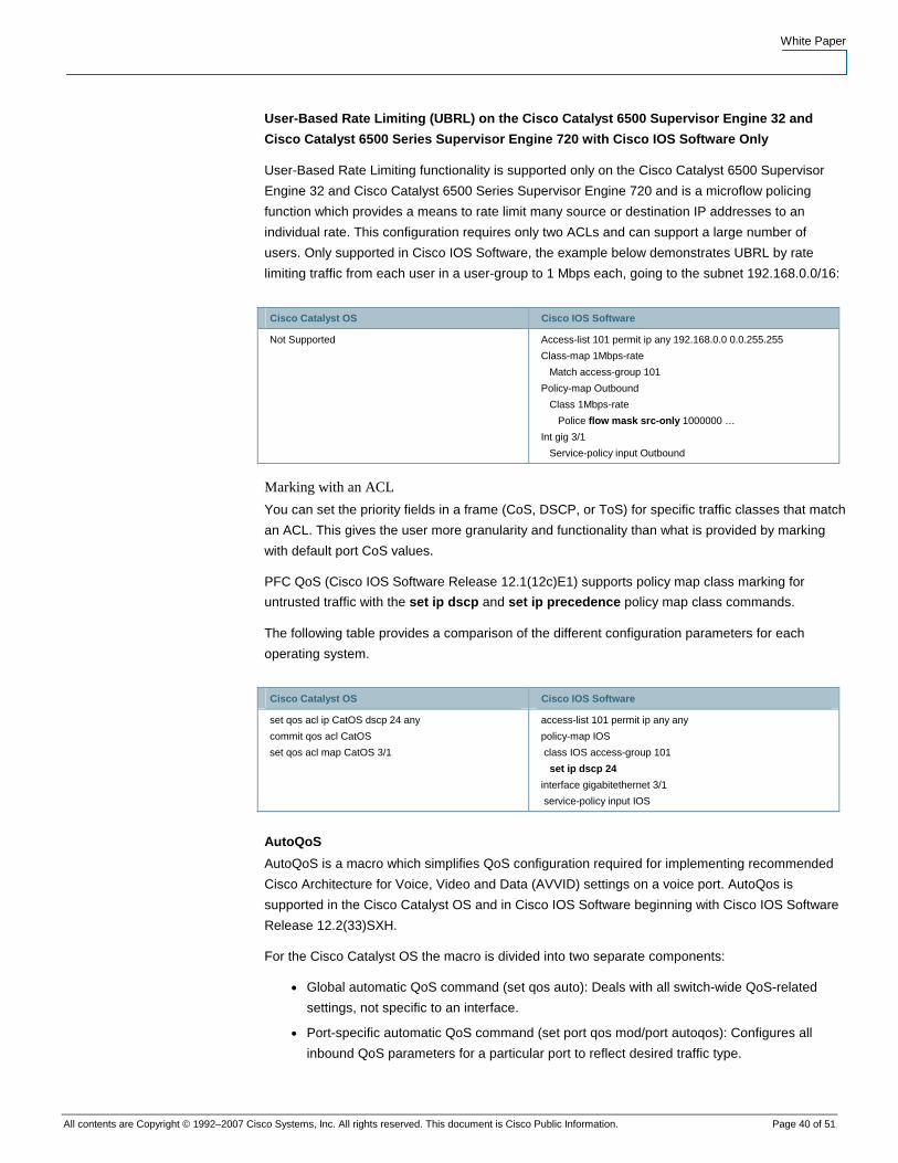
White Paper
All contents are Copyright © 1992–2007 Cisco Systems, Inc. All rights reserved. This document is Cisco Public Information. Page 40 of 51
User-Based Rate Limiting (UBRL) on the Cisco Catalyst 6500 Supervisor Engine 32 and
Cisco Catalyst 6500 Series Supervisor Engine 720 with Cisco IOS Software Only
User-Based Rate Limiting functionality is supported only on the Cisco Catalyst 6500 Supervisor
Engine 32 and Cisco Catalyst 6500 Series Supervisor Engine 720 and is a microflow policing
function which provides a means to rate limit many source or destination IP addresses to an
individual rate. This configuration requires only two ACLs and can support a large number of
users. Only supported in Cisco IOS Software, the example below demonstrates UBRL by rate
limiting traffic from each user in a user-group to 1 Mbps each, going to the subnet 192.168.0.0/16:
Cisco Catalyst OS Cisco IOS Software
Not Supported Access-list 101 permit ip any 192.168.0.0 0.0.255.255
Class-map 1Mbps-rate
Match access-group 101
Policy-map Outbound
Class 1Mbps-rate
Police flow mask src-only 1000000 …
Int gig 3/1
Service-policy input Outbound
Marking with an ACL
You can set the priority fields in a frame (CoS, DSCP, or ToS) for specific traffic classes that match
an ACL. This gives the user more granularity and functionality than what is provided by marking
with default port CoS values.
PFC QoS (Cisco IOS Software Release 12.1(12c)E1) supports policy map class marking for
untrusted traffic with the set ip dscp and set ip precedence policy map class commands.
The following table provides a comparison of the different configuration parameters for each
operating system.
Cisco Catalyst OS Cisco IOS Software
set qos acl ip CatOS dscp 24 any
commit qos acl CatOS
set qos acl map CatOS 3/1
access-list 101 permit ip any any
policy-map IOS
class IOS access-group 101
set ip dscp 24
interface gigabitethernet 3/1
service-policy input IOS
AutoQoS
AutoQoS is a macro which simplifies QoS configuration required for implementing recommended
Cisco Architecture for Voice, Video and Data (AVVID) settings on a voice port. AutoQos is
supported in the Cisco Catalyst OS and in Cisco IOS Software beginning with Cisco IOS Software
Release 12.2(33)SXH.
For the Cisco Catalyst OS the macro is divided into two separate components:
● Global automatic QoS command (set qos auto): Deals with all switch-wide QoS-related
settings, not specific to an interface.
● Port-specific automatic QoS command (set port qos mod/port autoqos): Configures all
inbound QoS parameters for a particular port to reflect desired traffic type.
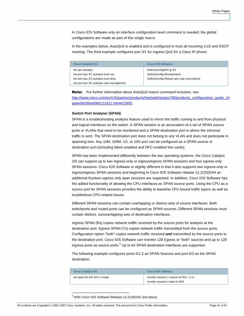
White Paper
All contents are Copyright © 1992–2007 Cisco Systems, Inc. All rights reserved. This document is Cisco Public Information. Page 41 of 51
In Cisco IOS Software only an interface configuration level command is needed; the global
configurations are made as part of this single macro.
In the examples below, AutoQoS is enabled and is configured to trust all incoming CoS and DSCP
marking. The third example configures port 3/1 for ingress QoS for a Cisco IP phone:
Cisco Catalyst OS Cisco IOS Software
set qos autoqos
set port qos 3/1 autoqos trust cos
set port qos 3/1 autoqos trust dscp
set port qos 3/1 autoqos voip ciscoipphone
Switch(config)#int gi 3/1
Switch(config-if)#switchport
Switch(config-if)#auto qos voip cisco-phone
Note: For further information about AutoQoS macro command inclusion, see
http://www.cisco.com/en/US/partner/products/hw/switches/ps708/products_configuration_guide_ch
apter09186a0080121d11.html#22805.
Switch Port Analyzer (SPAN)
SPAN is a troubleshooting analysis feature used to mirror the traffic coming to and from physical
and logical interfaces on the switch. A SPAN session is an association of a set of SPAN source
ports or VLANs that need to be monitored and a SPAN destination port is where the mirrored
traffic is sent. The SPAN destination port does not belong to any VLAN and does not participate in
spanning tree. Any 10M, 100M, 1G, or 10G port can be configured as a SPAN source or
destination port (including fabric-enabled and DFC-enabled line cards).
SPAN has been implemented differently between the two operating systems. the Cisco Catalyst
OS can support up to two ingress-only or ingress/egress SPAN sessions and four egress-only
SPAN sessions. Cisco IOS Software is slightly different in that it also supports two ingress-only or
ingress/egress SPAN sessions and beginning in Cisco IOS Software release 12.2(33)SXH an
additional fourteen egress only span sessions are supported. In addition, Cisco IOS Software has
the added functionality of allowing the CPU interfaces as SPAN source ports. Using the CPU as a
source port for SPAN sessions provides the ability to baseline CPU bound traffic typers as well as
troubleshoot CPU related issues.
Different SPAN sessions can contain overlapping or distinct sets of source interfaces. Both
switchports and routed ports can be configured as SPAN sources. Different SPAN sessions must
contain distinct, nonoverlapping sets of destination interfaces.
Ingress SPAN (Rx) copies network traffic received by the source ports for analysis at the
destination port. Egress SPAN (Tx) copies network traffic transmitted from the source ports.
Configuration option "both" copies network traffic received and transmitted by the source ports to
the destination port. Cisco IOS Software can monitor 128 Egress or “both” sources and up to 128
ingress ports as source ports.5 Up to 64 SPAN destination interfaces are supported.
The following example configures ports 5/1-2 as SPAN Sources and port 5/3 as the SPAN
destination.
Cisco Catalyst OS Cisco IOS Software
set span 5/1,5/2 5/3 rx create monitor session 1 source int f5/1—2 rx
monitor session 1 dest int f5/3
5 With Cisco IOS Software Release 12.2(18)SXE and above.
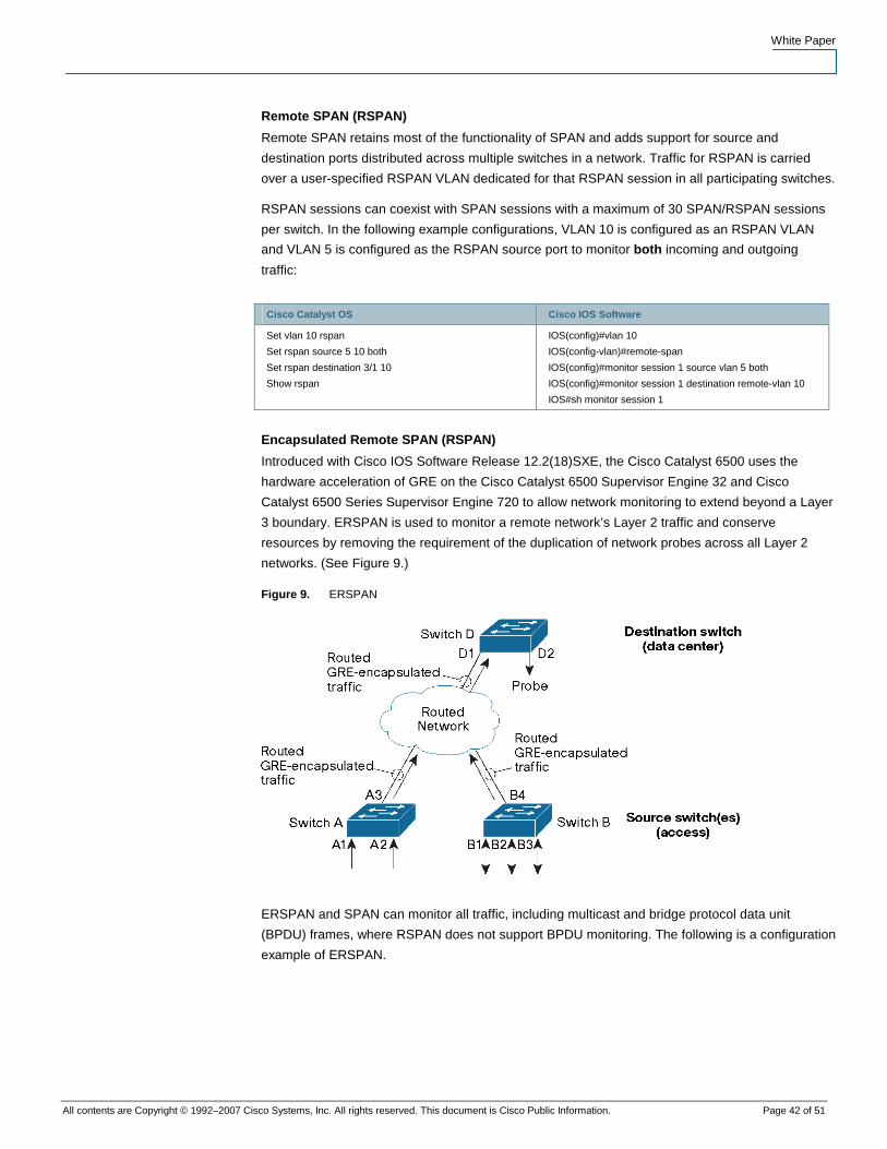
White Paper
All contents are Copyright © 1992–2007 Cisco Systems, Inc. All rights reserved. This document is Cisco Public Information. Page 42 of 51
Remote SPAN (RSPAN)
Remote SPAN retains most of the functionality of SPAN and adds support for source and
destination ports distributed across multiple switches in a network. Traffic for RSPAN is carried
over a user-specified RSPAN VLAN dedicated for that RSPAN session in all participating switches.
RSPAN sessions can coexist with SPAN sessions with a maximum of 30 SPAN/RSPAN sessions
per switch. In the following example configurations, VLAN 10 is configured as an RSPAN VLAN
and VLAN 5 is configured as the RSPAN source port to monitor both incoming and outgoing
traffic:
Cisco Catalyst OS Cisco IOS Software
Set vlan 10 rspan
Set rspan source 5 10 both
Set rspan destination 3/1 10
Show rspan
IOS(config)#vlan 10
IOS(config-vlan)#remote-span
IOS(config)#monitor session 1 source vlan 5 both
IOS(config)#monitor session 1 destination remote-vlan 10
IOS#sh monitor session 1
Encapsulated Remote SPAN (RSPAN)
Introduced with Cisco IOS Software Release 12.2(18)SXE, the Cisco Catalyst 6500 uses the
hardware acceleration of GRE on the Cisco Catalyst 6500 Supervisor Engine 32 and Cisco
Catalyst 6500 Series Supervisor Engine 720 to allow network monitoring to extend beyond a Layer
3 boundary. ERSPAN is used to monitor a remote network’s Layer 2 traffic and conserve
resources by removing the requirement of the duplication of network probes across all Layer 2
networks. (See Figure 9.)
Figure 9. ERSPAN
ERSPAN and SPAN can monitor all traffic, including multicast and bridge protocol data unit
(BPDU) frames, where RSPAN does not support BPDU monitoring. The following is a configuration
example of ERSPAN.
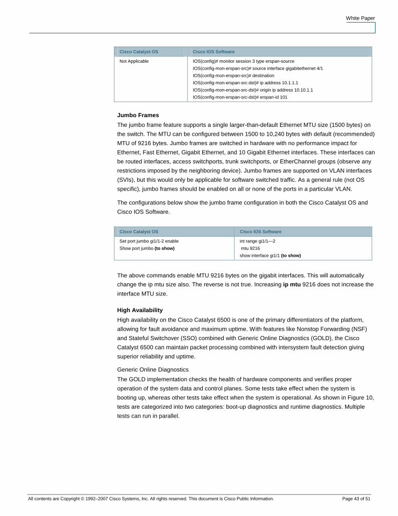
White Paper
All contents are Copyright © 1992–2007 Cisco Systems, Inc. All rights reserved. This document is Cisco Public Information. Page 43 of 51
Cisco Catalyst OS Cisco IOS Software
Not Applicable IOS(config)# monitor session 3 type erspan-source
IOS(config-mon-erspan-src)# source interface gigabitethernet 4/1
IOS(config-mon-erspan-src)# destination
IOS(config-mon-erspan-src-dst)# ip address 10.1.1.1
IOS(config-mon-erspan-src-dst)# origin ip address 10.10.1.1
IOS(config-mon-erspan-src-dst)# erspan-id 101
Jumbo Frames
The jumbo frame feature supports a single larger-than-default Ethernet MTU size (1500 bytes) on
the switch. The MTU can be configured between 1500 to 10,240 bytes with default (recommended)
MTU of 9216 bytes. Jumbo frames are switched in hardware with no performance impact for
Ethernet, Fast Ethernet, Gigabit Ethernet, and 10 Gigabit Ethernet interfaces. These interfaces can
be routed interfaces, access switchports, trunk switchports, or EtherChannel groups (observe any
restrictions imposed by the neighboring device). Jumbo frames are supported on VLAN interfaces
(SVIs), but this would only be applicable for software switched traffic. As a general rule (not OS
specific), jumbo frames should be enabled on all or none of the ports in a particular VLAN.
The configurations below show the jumbo frame configuration in both the Cisco Catalyst OS and
Cisco IOS Software.
Cisco Catalyst OS Cisco IOS Software
Set port jumbo gi1/1-2 enable
Show port jumbo (to show)
int range gi1/1—2
mtu 9216
show interface gi1/1 (to show)
The above commands enable MTU 9216 bytes on the gigabit interfaces. This will automatically
change the ip mtu size also. The reverse is not true. Increasing ip mtu 9216 does not increase the
interface MTU size.
High Availability
High availability on the Cisco Catalyst 6500 is one of the primary differentiators of the platform,
allowing for fault avoidance and maximum uptime. With features like Nonstop Forwarding (NSF)
and Stateful Switchover (SSO) combined with Generic Online Diagnostics (GOLD), the Cisco
Catalyst 6500 can maintain packet processing combined with intersystem fault detection giving
superior reliability and uptime.
Generic Online Diagnostics
The GOLD implementation checks the health of hardware components and verifies proper
operation of the system data and control planes. Some tests take effect when the system is
booting up, whereas other tests take effect when the system is operational. As shown in Figure 10,
tests are categorized into two categories: boot-up diagnostics and runtime diagnostics. Multiple
tests can run in parallel.
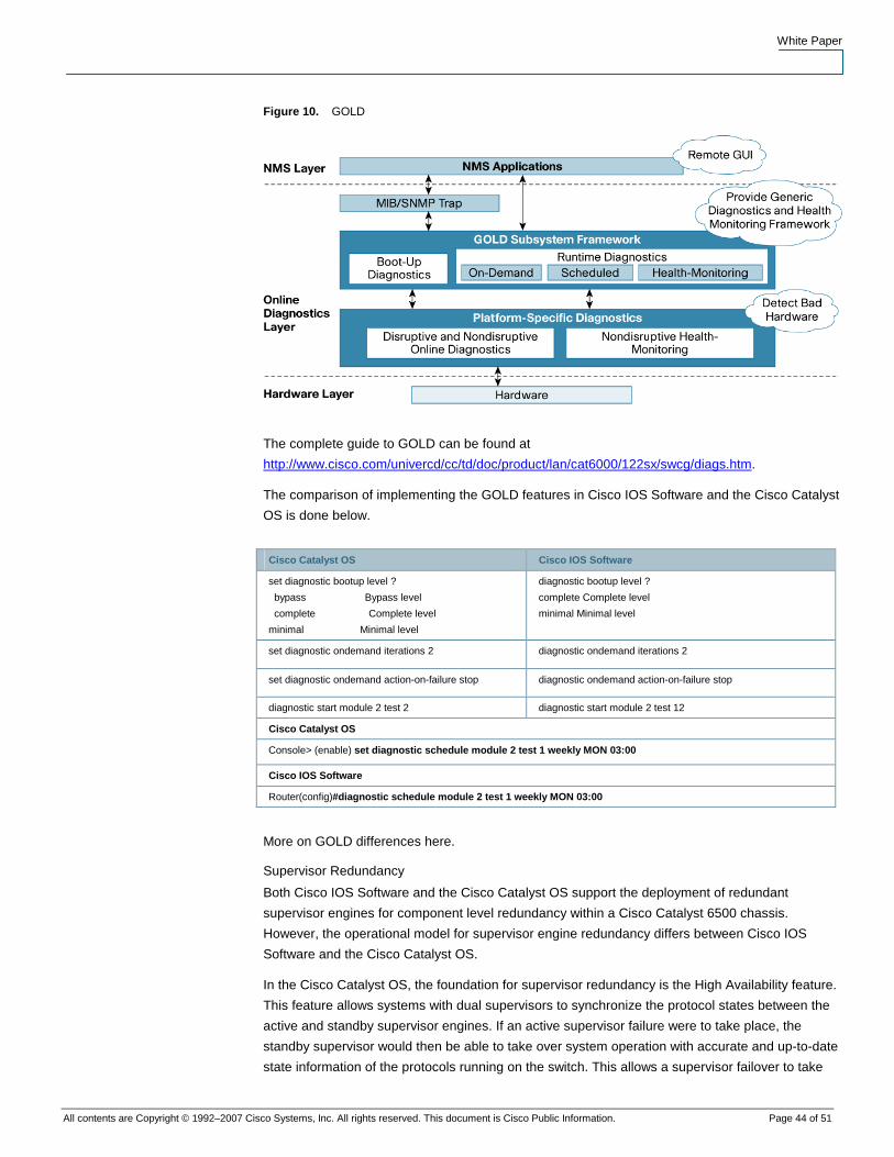
White Paper
All contents are Copyright © 1992–2007 Cisco Systems, Inc. All rights reserved. This document is Cisco Public Information. Page 44 of 51
Figure 10. GOLD
The complete guide to GOLD can be found at
http://www.cisco.com/univercd/cc/td/doc/product/lan/cat6000/122sx/swcg/diags.htm.
The comparison of implementing the GOLD features in Cisco IOS Software and the Cisco Catalyst
OS is done below.
Cisco Catalyst OS Cisco IOS Software
set diagnostic bootup level ?
bypass Bypass level
complete Complete level
minimal Minimal level
diagnostic bootup level ?
complete Complete level
minimal Minimal level
set diagnostic ondemand iterations 2 diagnostic ondemand iterations 2
set diagnostic ondemand action-on-failure stop diagnostic ondemand action-on-failure stop
diagnostic start module 2 test 2 diagnostic start module 2 test 12
Cisco Catalyst OS
Console> (enable) set diagnostic schedule module 2 test 1 weekly MON 03:00
Cisco IOS Software
Router(config)#diagnostic schedule module 2 test 1 weekly MON 03:00
More on GOLD differences here.
Supervisor Redundancy
Both Cisco IOS Software and the Cisco Catalyst OS support the deployment of redundant
supervisor engines for component level redundancy within a Cisco Catalyst 6500 chassis.
However, the operational model for supervisor engine redundancy differs between Cisco IOS
Software and the Cisco Catalyst OS.
In the Cisco Catalyst OS, the foundation for supervisor redundancy is the High Availability feature.
This feature allows systems with dual supervisors to synchronize the protocol states between the
active and standby supervisor engines. If an active supervisor failure were to take place, the
standby supervisor would then be able to take over system operation with accurate and up-to-date
state information of the protocols running on the switch. This allows a supervisor failover to take
White Paper
All contents are Copyright © 1992–2007 Cisco Systems, Inc. All rights reserved. This document is Cisco Public Information. Page 45 of 51
place in one to three seconds and requires no network reconvergence for Layer 2, 3, and 4
protocols. From a router perspective, the MSFC engines can be configured for redundancy as well
with hybrid software. For more information on hybrid High Availability, refer to the white paper at
http://www.cisco.com/warp/public/cc/pd/si/casi/ca6000/tech/hafc6_wp.pdf.
Cisco IOS Software on the Cisco Catalyst 6500 supports Route Processor Redundancy (RPR,
also known as Enhanced High System Availability [EHSA]), Route Processor Redundancy Plus
(RPR+), and Nonstop Forwarding with Stateful Switchover (NSF/SSO). In this operational model,
one supervisor/MSFC pair is fully operational and the other pair is in standby mode. The show
module command lists the current and standby supervisors. There are heartbeat messages
between two pairs to help ensure rapid failure detection. The RPR and RPR+ implementations do
not synchronize protocol state between the two supervisor engines; however, the SSO
implementation synchronizes protocol state. The following section provides an overview of
supervisor redundancy characteristics that are equivalent between RPR, RPR+, and SSO.
In Cisco IOS Software, the supervisor and MSFC are each responsible for different functions and
protocols (Layer 2 vs. Layer 3). However, the system is dependent on both engines being available
for proper operation. Failure of either the supervisor or the MSFC in RPR/RPR+/SSO mode will
cause a switchover from the active supervisor to the standby supervisor/MSFC. Note that in the
Cisco Catalyst OS, the supervisor can remain fully operational if one MSFC fails; an MSFC failure
does not necessarily cause a supervisor switchover, but may cause an MSFC failover only,
allowing a cross model where the active PFC and the switch processor running the Cisco Catalyst
OS are fully functional in slot 1 whereas the route processor/MSFC are fully functional in slot 2.
There is no stateful protocol redundancy between supervisor engines with RPR or RPR+. The
SSO redundancy mode provides the stateful protocol redundancy between supervisor engines in
Cisco IOS Software and is equivalent in terms of functionality to the Cisco Catalyst OS High
Availability redundancy mode.
The following section provides an overview of supervisor redundancy characteristics with RPR,
RPR+, and NSF/SSO.
Route Processor Redundancy (RPR)
With RPR enabled, the active supervisor and MSFC are operational and responsible for all packet
forwarding and features. The standby supervisor and MSFC are out of reset, but not all
subsystems are booted. The standby supervisor is booted to the point where the gigabit uplink
ports are operational, but no protocols are running on the supervisor or MSFC.
Upon an active supervisor failure, RPR detects the loss of the active supervisor and causes a
switchover. The line cards are power-cycled, the supervisor and MSFC finish booting, and all
Layer 2 and Layer 3 protocols are initialized. The failover time for the system to start forwarding
traffic in EHSA is approximately 90 seconds. The actual failover time is dependent on the size and
complexity of the configuration.
With RPR, the startup configuration and boot variables are synchronized between the active and
standby supervisor.
Route Processor Redundancy Plus (RPR+)
With RPR+ enabled, the active supervisor and MSFC are operational and responsible for all
packet forwarding and features. The standby supervisor and MSFC are fully booted and running
on standby. RPR+ is an enhancement to RPR. Since the standby supervisor is further along in the
boot process, RPR+ provides a faster supervisor failover than RPR. In addition, the line card state
White Paper
All contents are Copyright © 1992–2007 Cisco Systems, Inc. All rights reserved. This document is Cisco Public Information. Page 46 of 51
is maintained during a supervisor failover. This helps to reduce the failover time. However, the port
states are not maintained, so connections to other devices will flap.
The failover time for the system to start forwarding traffic in RPR+ is approximately 30 seconds.
The actual failover time is dependent on the size and complexity of the configuration.
Nonstop Forwarding with Stateful Switchover (NSF/SSO)
Both Cisco IOS Software and the Cisco Catalyst OS support NSF with SSO. The primary
differentiators apply in where and how these features are applied, with the more advanced forms of
these features being deployed first in Cisco IOS Software. SSO expands the RPR+ capabilities to
provide transparent failover of Layer 2 protocols when a supervisor failure occurs. SSO is stateful
for Layer 2 protocols. PFC and Distributed Forwarding Card (DFC) hardware tables are maintained
across a switchover. This allows for transparent failover at Layer 2 and Layer 4. NSF works in
conjunction with SSO to help ensure Layer 3 integrity following a switchover. It allows a router
experiencing the failure of an active supervisor to continue forwarding data packets along known
routes while the routing protocol information is recovered and validated. This forwarding can
continue to take place by using graceful restart mechanisms that allow peering arrangements to
recover upon failover, thus avoiding unnecessary route flaps and network instability.
The failover time is 0 to 3 seconds with NSF/SSO. More information on NSF/SSO can be found at
http://www.cisco.com/en/US/prod/collateral/switches/ps5718/ps708/prod_white_paper0900aecd80
1c5cd7.shtml.
Hot Standby Router Protocol (HSRP)
The Hot Standby Router Protocol (HSRP) provides network redundancy for IP networks, helping
ensure that user traffic immediately and transparently recovers from first hop failures in network
edge devices or access circuits. HSRP provides a Layer 2 and Layer 3 virtual address that is
shared between two or more Cisco routing devices to help ensure network resiliency. It uses an
election algorithm combined with statically assigned virtual IP address and Layer 2 MAC address
for transparent fault recovery. For more information, visit
http://www.cisco.com/en/US/partner/tech/tk648/tk362/tk321/tsd_technology_support_sub-
protocol_home.html.
Virtual Router Redundancy Protocol (VRRP)
The Virtual Router Redundancy Protocol (VRRP) provides a function very similar to the Cisco
proprietary Hot Standby Router Protocol (HSRP). VRRP is designed to eliminate the single point of
failure inherent in a static default routed environment. VRRP specifies an election protocol that
dynamically assigns responsibility for a virtual router to one of the VRRP routers on a LAN. The
VRRP router controlling the IP address(es) associated with a virtual router is called the Master,
and forwards packets sent to these IP addresses. The election process provides dynamic failover
in the forwarding responsibility should the Master become unavailable. Any of the virtual router's IP
addresses on a LAN can then be used as the default first hop router by end hosts. The advantage
gained from using VRRP is a higher availability default path without requiring configuration of
dynamic routing or router discovery protocols on every end host.
Gateway Load Balancing Protocol (GLBP)
The Gateway Load Balancing Protocol (GLBP) provides load-balancing over multiple gateways
through a single virtual IP address and multiple virtual MAC addresses. This protocol is similar to
Host Standby Router Protocol (HSRP) and Virtual Router Redundancy Protocol (VRRP). GLBP
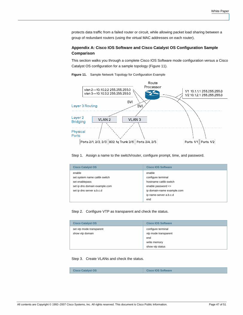
White Paper
All contents are Copyright © 1992–2007 Cisco Systems, Inc. All rights reserved. This document is Cisco Public Information. Page 47 of 51
protects data traffic from a failed router or circuit, while allowing packet load sharing between a
group of redundant routers (using the virtual MAC addresses on each router).
Appendix A: Cisco IOS Software and Cisco Catalyst OS Configuration Sample Comparison
This section walks you through a complete Cisco IOS Software mode configuration versus a Cisco
Catalyst OS configuration for a sample topology (Figure 11).
Figure 11. Sample Network Topology for Configuration Example
Step 1. Assign a name to the switch/router, configure prompt, time, and password.
Cisco Catalyst OS Cisco IOS Software
enable
set system name cat6k-switch
set enablepass
set ip dns domain example.com
set ip dns server a.b.c.d
enable
configure terminal
hostname cat6k-switch
enable password <>
ip domain-name example.com
ip name-server a.b.c.d
end
Step 2. Configure VTP as transparent and check the status.
Cisco Catalyst OS Cisco IOS Software
set vtp mode transparent
show vtp domain
configure terminal
vtp mode transparent
end
write memory
show vtp status
Step 3. Create VLANs and check the status.
Cisco Catalyst OS Cisco IOS Software
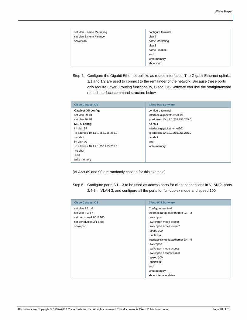
White Paper
All contents are Copyright © 1992–2007 Cisco Systems, Inc. All rights reserved. This document is Cisco Public Information. Page 48 of 51
set vlan 2 name Marketing
set vlan 3 name Finance
show vlan
configure terminal
vlan 2
name Marketing
vlan 3
name Finance
end
write memory
show vlan
Step 4. Configure the Gigabit Ethernet uplinks as routed interfaces. The Gigabit Ethernet uplinks
1/1 and 1/2 are used to connect to the remainder of the network. Because these ports
only require Layer 3 routing functionality, Cisco IOS Software can use the straightforward
routed interface command structure below:
Cisco Catalyst OS Cisco IOS Software
Catalyst OS config:
set vlan 89 1/1
set vlan 90 1/2
MSFC config:
int vlan 89
ip address 10.1.1.1 255.255.255.0
no shut
int vlan 90
ip address 10.1.2.1 255.255.255.0
no shut
end
write memory
configure terminal
interface gigabitethernet 1/1
ip address 10.1.1.1 255.255.255.0
no shut
interface gigabitethernet1/2
ip address 10.1.2.1 255.255.255.0
no shut
end
write memory
[VLANs 89 and 90 are randomly chosen for this example]
Step 5. Configure ports 2/1—3 to be used as access ports for client connections in VLAN 2, ports
2/4-5 in VLAN 3, and configure all the ports for full-duplex mode and speed 100.
Cisco Catalyst OS Cisco IOS Software
set vlan 2 2/1-3
set vlan 3 2/4-5
set port speed 2/1-5 100
set port duplex 2/1-5 full
show port
Configure terminal
interface range fastethernet 2/1—3
switchport
switchport mode access
switchport access vlan 2
speed 100
duplex full
interface range fastethernet 2/4—5
switchport
switchport mode access
switchport access vlan 3
speed 100
duplex full
end
write memory
show interface status
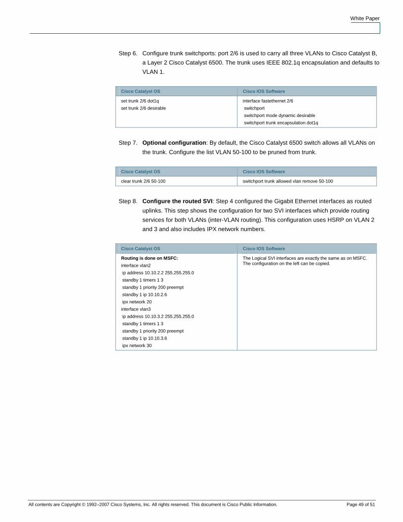
White Paper
All contents are Copyright © 1992–2007 Cisco Systems, Inc. All rights reserved. This document is Cisco Public Information. Page 49 of 51
Step 6. Configure trunk switchports: port 2/6 is used to carry all three VLANs to Cisco Catalyst B,
a Layer 2 Cisco Catalyst 6500. The trunk uses IEEE 802.1q encapsulation and defaults to
VLAN 1.
Cisco Catalyst OS Cisco IOS Software
set trunk 2/6 dot1q
set trunk 2/6 desirable
interface fastethernet 2/6
switchport
switchport mode dynamic desirable
switchport trunk encapsulation dot1q
Step 7. Optional configuration: By default, the Cisco Catalyst 6500 switch allows all VLANs on
the trunk. Configure the list VLAN 50-100 to be pruned from trunk.
Cisco Catalyst OS Cisco IOS Software
clear trunk 2/6 50-100 switchport trunk allowed vlan remove 50-100
Step 8. Configure the routed SVI: Step 4 configured the Gigabit Ethernet interfaces as routed
uplinks. This step shows the configuration for two SVI interfaces which provide routing
services for both VLANs (inter-VLAN routing). This configuration uses HSRP on VLAN 2
and 3 and also includes IPX network numbers.
Cisco Catalyst OS Cisco IOS Software
Routing is done on MSFC:
interface vlan2
ip address 10.10.2.2 255.255.255.0
standby 1 timers 1 3
standby 1 priority 200 preempt
standby 1 ip 10.10.2.6
ipx network 20
interface vlan3
ip address 10.10.3.2 255.255.255.0
standby 1 timers 1 3
standby 1 priority 200 preempt
standby 1 ip 10.10.3.6
ipx network 30
The Logical SVI interfaces are exactly the same as on MSFC. The configuration on the left can be copied.
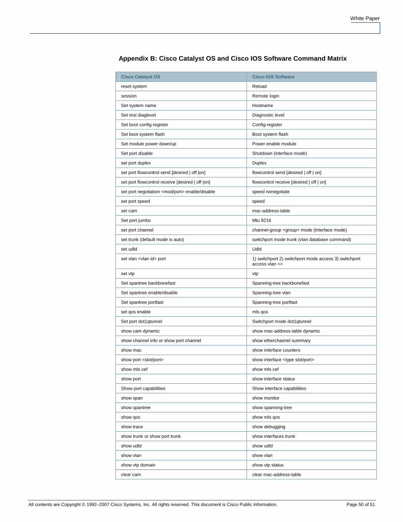
White Paper
All contents are Copyright © 1992–2007 Cisco Systems, Inc. All rights reserved. This document is Cisco Public Information. Page 50 of 51
Appendix B: Cisco Catalyst OS and Cisco IOS Software Command Matrix
Cisco Catalyst OS Cisco IOS Software
reset system Reload
session Remote login
Set system name Hostname
Set test diaglevel Diagnostic level
Set boot config-register Config-register
Set boot system flash Boot system flash
Set module power down/up Power enable module
Set port disable Shutdown (interface mode)
set port duplex Duplex
set port flowcontrol send [desired | off |on] flowcontrol send [desired | off | on]
set port flowcontrol receive [desired | off |on] flowcontrol receive [desired | off | on]
set port negotiation <mod/port> enable/disable speed nonegotiate
set port speed speed
set cam mac-address-table
Set port jumbo Mtu 9216
set port channel channel-group <group> mode (interface mode)
set trunk (default mode is auto) switchport mode trunk (vlan database command)
set udld Udld
set vlan <vlan id> port 1) switchport 2) switchport mode access 3) switchport access vlan <>
set vtp vtp
Set spantree backbonefast Spanning-tree backbonefast
Set spantree enable/disable Spanning-tree vlan
Set spantree portfast Spanning-tree portfast
set qos enable mls qos
Set port dot1qtunnel Switchport mode dot1qtunnel
show cam dynamic show mac-address-table dynamic
show channel info or show port channel show etherchannel summary
show mac show interface counters
show port <slot/port> show interface <type slot/port>
show mls cef show mls cef
show port show interface status
Show port capabilities Show interface capabilities
show span show monitor
show spantree show spanning-tree
show qos show mls qos
show trace show debugging
show trunk or show port trunk show interfaces trunk
show udld show udld
show vlan show vlan
show vtp domain show vtp status
clear cam clear mac-address-table

White Paper
All contents are Copyright © 1992–2007 Cisco Systems, Inc. All rights reserved. This document is Cisco Public Information. Page 51 of 51
Appendix C: Conversion Procedures
Software conversion from hybrid to native Cisco IOS Software on a Cisco Catalyst 6000 Series
Switch
http://www.cisco.com/en/US/partner/products/hw/switches/ps708/products_tech_note09186a0080
15bfa6.shtml.
Software conversion from native Cisco IOS Software to hybrid on a Cisco Catalyst 6000 Series
Switch
http://www.cisco.com/en/US/partner/products/hw/switches/ps700/products_tech_note09186a0080
1350b8.shtml.
Printed in USA C11-423714-00 8/07


![NetFlow, RMON and Cisco-NAM deployment...NetFlow, RMON and Cisco-NAM deployment. [Technical Report] RT-0343, INRIA. 2007, pp.27. inria-00169995v3 Theme COM` INSTITUT NATIONAL DE RECHERCHE](https://img.pdfslide.us/doc/110x75/5fb25179b2a0e14642069483/netflow-rmon-and-cisco-nam-deployment-netflow-rmon-and-cisco-nam-deployment.jpg)