Embed Size (px)
Citation preview
Comparison of Multi-Area Load Frequency Control by PI and Fuzzy Logic Controller Using SMES| ISSN: 2321-9939
IJEDR1303024 INTERNATIONAL JOURNAL OF ENGINEERING DEVELOPMENT AND RESEARCH | IJEDR
Website: www.ijedr.org | Email ID: [email protected] 114
Comparison of Multi-Area Load Frequency Control by
PI and Fuzzy Logic Controller Using SMES 1K.J.D. Venkatesh,
2D.V.N.Ananth,
3B.Rajesh
VITAM College of Engineering, Dept. of Electrical Engineering Visakhapatnam, India [email protected] , [email protected] , [email protected]
Abstract— In this paper a Fuzzy Logic based load frequency control system (LFC) with Superconductor Magnetic Energy Storage System
(SMES) in a multi area electric power system was explained. If a large power imbalance is suddenly happened in a multi area power electric
system, generation units and also consumer sides will be affected by the distortion in the energy balance between both two sides. This
imbalance is initially handled by the kinetic energy of the system rotating components such as turbines, generators and motors, but,
eventually, the frequency will change. Therefore, Load Frequency Control (LFC) is considered as one of the most challenging issues in
power system control and operation. PID type controllers are conventional solutions for LFC. The parameters of the PID controllers have
been tuned traditionally. In this paper, a PID controller is applied for the LFC problem to stabilize the system after disturbances like load
changing and further oscillations are damped by using SMES. To illustrate the application of the method, a multi area network with some
uncertainties is provided. Finally the results of the Load Frequency controller are compared without SMES and SMES and also effect of
variation of parameters for PI like (Ki) are studied. It is also further studied the performance of the system with PI and FLC techniques.
The simulation results show the success and the validity of the PID controller in compare with the FLC controller.
Index Terms—Multi Area Electric Power System, Load Frequency Control, Fuzzy Logic Controller, PI Controller, SMES.
I. INTRODUCTION
Generation and distribution of electric energy with good reliability and quality is very important in power system operation and
control. This is achieved by Automatic Generation Control (AGC). In an interconnected power system, as the load demand varies
randomly, the area frequency and tie-line power interchange also vary. The objective of Load Frequency Control (LFC) is to
minimize the transient deviations in these variables and to ensure for their steady state values to be zero. The LFC performed by only
a governor control imposes a limit on the degree to which the deviations in frequency and tie-line power exchange can be minimized.
However, as the LFC is fundamentally for the problem of an instantaneous mismatch between the generation and demand of active
power, the incorporation of a fast-acting energy storage device in the power system can improve the performance under such
conditions. But fixed gain controllers based on classical control theories are presently used. These are insufficient because of changes
in operating points during a daily cycle [Benjamin et al., 1978; Nanda et al., 1988; Das et al., 1990; Mufti et al., 2007; Nanda et al.,
2006 & Oysal et al., 2004] and are not suitable for all operating conditions.
Therefore, variable structure controller [Benjamin et al., 1982; Sivaramaksishana et al., 1984; Tripathy et al., 1997 & Shayeghi et
al., 2004] has been proposed for AGC. For designing controllers based on these techniques, the perfect model is required which has
to track the state variables and satisfy system constraints. Therefore it is difficult to apply these adaptive control techniques to AGC in
practical implementations. In multi-area power system, if a load variation occurs at any one of the areas in the system, the frequency
related with this area is affected first and then that of other areas are also affected from this perturbation through tie lines. When a
small load disturbance occurs, power system frequency oscillations continue for a long duration, even in the case with optimized gain
of integral controllers [Sheikh et al., 2008 & Demiroren, 2002]. So, to damp out the oscillations in the shortest possible time,
automatic generation control including SMES unit is proposed.
Therefore, in the proposed control system, with an addition of the simple SMES controller, a supplementary controller with KIi (as
shown in Fig. 6) is designed in order to retain the frequency to the set value after load changes. These controllers must eliminate the
frequency transients as soon as possible. Using fuzzy logic, the integrator gain (KIi) of the supplementary controller is so scheduled
that it compromise between fast transient recovery and low overshoot in dynamic response of the system. It is seen that with the
addition of gain scheduled supplementary controller, a simple controller scheme for SMES is sufficient for load frequency control of
multi-area power system [Sheikh et al., 2008].
II. SUPERCONDUCTING MAGNETIC ENERGY STORAGE (SMES) SYSTEM
Overview of SMES
A superconducting magnetic energy storage system is a DC current device for storing and instantaneously discharging large
quantities of power. The DC current flowing through a superconducting wire in a large magnet creates the magnetic field. The large
superconducting coil is contained in a cryostat or dewar consisting of a vacuum vessel and a liquid vessel that cools the coil. A
cryogenic system and the power conversion/conditioning system with control and protection functions [IEEE Task Force, 2006] are
also used to keep the temperature well below the critical temperature of the superconductor. During SMES operation, the magnet coils
have to remain in the superconducting status. A refrigerator in the cryogenic system maintains the required temperature for proper
superconducting operation. A bypass switch is used to reduce energy losses when the coil is on standby. And it also serves other
Comparison of Multi-Area Load Frequency Control by PI and Fuzzy Logic Controller Using SMES| ISSN: 2321-9939
IJEDR1303024 INTERNATIONAL JOURNAL OF ENGINEERING DEVELOPMENT AND RESEARCH | IJEDR
Website: www.ijedr.org | Email ID: [email protected] 115
purposes such as bypassing DC coil current if utility tie is lost, removing converter from service, or protecting the coil if cooling is
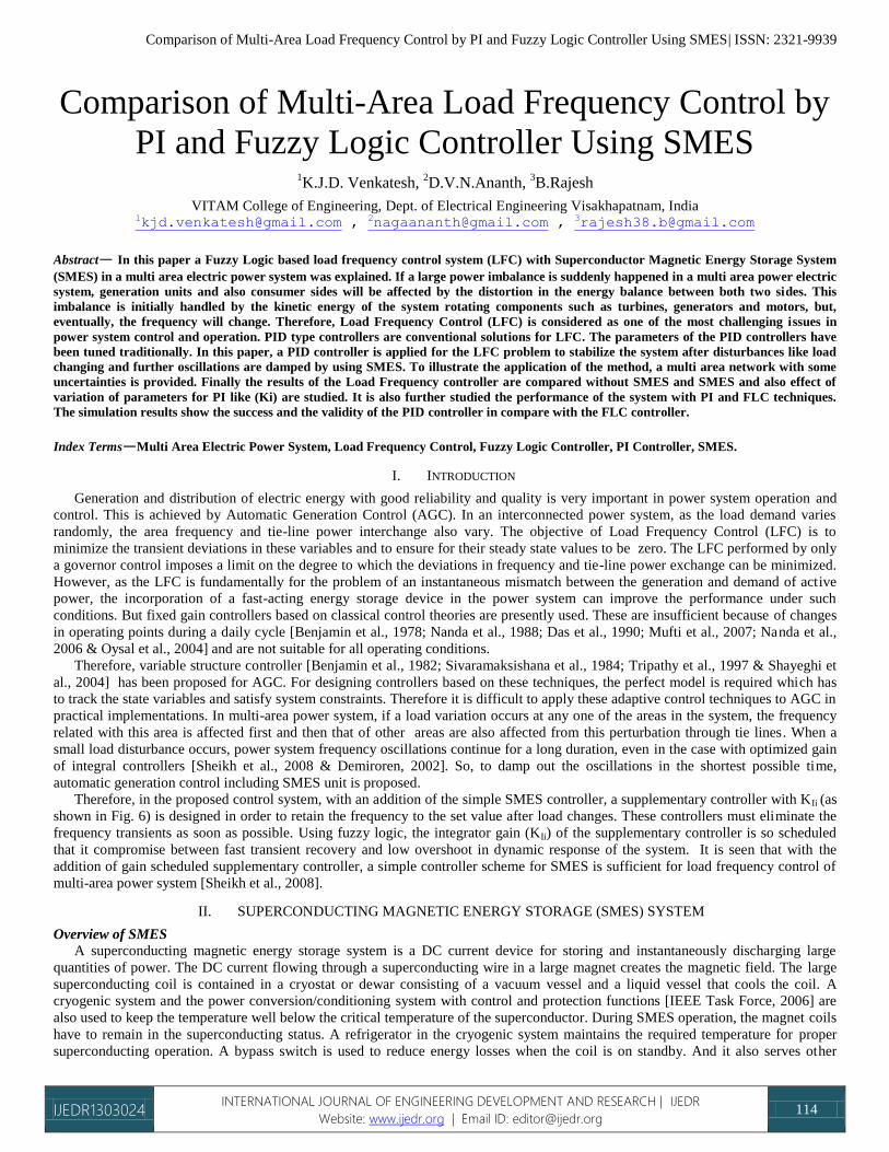
lost [M. H. Ali et al., 2008]. Figure 1 shows a basic schematic of an SMES system [http://www.doc.ic.ac.uk/~matti/ise2grp/ energy
storage_report/node8.html]. Utility system feeds the power to the power conditioning and switching devices that provides energy to
charge the coil, thus storing energy. When a voltage sag or momentary power outage occurs, the coil discharges through switching
and conditioning devices, feeding conditioned power to the load. The cryogenic (refrigeration) system and helium vessel keep the
conductor cold in order to maintain the coil in the superconducting state.
Fig. 1. Schematic diagram of the basic SMES system
Advantages of SMES
There are several reasons for using superconducting magnetic energy storage instead of other energy storage methods. The most
important advantages of SMES are that the time delay during charge and discharge is quite short. Power is available almost
instantaneously and very high power output can be provided for a brief period of time. Other energy storage methods, such as pumped
hydro or compressed air have a substantial time delay associated with the conversion of stored mechanical energy back into
electricity. Thus if a customer's demand is immediate, SMES is a viable option. Another advantage is that the loss of power is less
than other storage methods because the current encounters almost zero resistance.
Additionally the main parts in a SMES are motionless, which results in high reliability. Also,SMES systems are environmentally
friendly because superconductivity does not produce a chemical reaction. In addition, there are no toxins produced in the process.
The SMES is highly efficient at storing electricity (greater than 97% efficiency), and provide both real and reactive power. These
systems have been in use for several years to improve industrial power quality and to provide a premium-quality service for individual
customers vulnerable to voltage and power fluctuations. The SMES recharges within minutes and can repeat the charge/discharge
sequence thousands of times without any degradation of the magnet Thus it can help to minimize the frequency deviations due to load
variations [Demiroren & Yesil, 2004]. However, the SMES is still an expensive device.
[http://en.wikipedia.org/wiki/Superconducting_magnetic_energy_storage].
SMES for Load Frequency Control application
A sudden application of a load results in an instantaneous mismatch between the demand and supply of electrical power because
the generating plants are unable to change the inputs to the prime movers instantaneously. The immediate energy requirement is met
by the kinetic energy of the generator rotor and speed falls. So system frequency changes though it becomes normal after a short
period due to Automatic Generation Control. Again, sudden load rejections give rise to similar problems. The instantaneous surplus
generation created by removal of load is absorbed in the kinetic energy of the generator rotors and the frequency changes. The
problem of minimizing the deviation of frequency from normal value under such circumstances is known as the load frequency
control problem.
To be effective in load frequency control application, the energy storage system should be fast acting i.e. the time lag in switching
from receiving (charging) mode to delivering (discharging) mode should be very small. For damping the swing caused by small load
perturbations the storage units for LFC application need to have only a small quantity of stored energy, though its power rating has to
be high, since the stored energy has to be delivered within a short span of time. However, due to high cost of superconductor
technology, one can consider the use of non-superconducting of lossy magnetic energy storage (MES) inductors for the same purpose.
Such systems would be economical maintenance free, long lasting and as reliable as ordinary power transformers.
Thus a SMES system seems to be good to meet the above requirements. The power flow into an energy storage unit can be
reversed, by reversing the DC voltage applied to the inductor within a few cycles. A 12-pulse bridge converter with an appropriate
control of the firing angles can be adopted for the purpose. Thus, these fast acting energy storage devices can be made to share the
sudden load requirement with the generator rotors, by continuously controlling the power flow in or out of the inductor depending on
the frequency error signals.
III. ANALYSIS OF THE MAGNETIC ENERGY STORAGE UNIT
The SMES inductor converter unit for improvement in power system LFC application essentially consists of a DC inductor, an
ac/dc converter and a step down Y-Y/Δ transformer. The inductor should be wound with low resistance, large cross-section copper
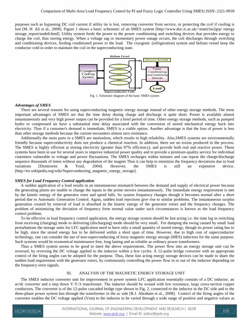
conductors. The converter is of the 12-pulse cascaded bridge type shown in Fig. 2, connected to the inductor in the DC side and to the
three-phase power system bus through the transformer in the ac side [R.J. Abraham et al., 2008]. Control of the firing angles of the
converter enables the DC voltage applied (Vsm) to the inductor to be varied through a wide range of positive and negative values as
Comparison of Multi-Area Load Frequency Control by PI and Fuzzy Logic Controller Using SMES| ISSN: 2321-9939
IJEDR1303024 INTERNATIONAL JOURNAL OF ENGINEERING DEVELOPMENT AND RESEARCH | IJEDR
Website: www.ijedr.org | Email ID: [email protected] 116
shown in Fig. 3. Gate turn off thyristors (GTO) allow us to design such type of converter. When charging the magnet, a positive DC
voltage is applied to the inductor. The current in the inductor rises exponentially or linearly and the magnetic energy is stored. When
the current reaches the rated value, the applied voltage is brought down to low value, sufficient to overcome the voltage drop due to
inductor resistance. When the extra energy is required in the power system, a negative DC voltage is applied to the inductor by
controlling the firing angles of the converter. The losses in the MES unit would consist of the transformer losses, the converter losses,
and the resistive loss in the inductor coil. The inductor loss can be kept at an acceptable level by proper design of the winding.
Fig. 2. Schematic diagram of the SMES unit
Fig. 3. Effect of inductor voltage, Vsm with the variation of firing angle of 12-pulse converter
Due to sudden application or rejection of load, the generator speed fluctuates. When the system load increases, the speed falls at
the first instant. However, due to the governor action, the speed oscillates around some reference value. The converter works as an
inverter ( 90 < <270 α DD) when the actual speed is less than the reference speed and energy is withdrawn from the SMES unit (Psm
negative). However, the energy is recovered when the speed swings to the other side.
The converter then works as a rectifier ( -90 < <90 α DD) and the power Psm becomes positive.
If the transformer and converter losses are neglected, according to the circuit analysis of converter, the voltage Vsm of the D.C
side of the 12-pulse converter under equal-α (EA, when α1 = α2 = α) mode is expressed by
where
α is the firing angle
Vsm is the DC voltage applied to the inductor
Ism is the current through the inductor
Rc is the equivalent commutating resistance and
Vsm0 is the maximum open circuit bridge voltage of each 6-pulse bridge at α=0.
When the inductor is charged initially, the current build up, expressed, as a function of time with Vsm held constant, is given as
where L and RL are the inductance and the resistance of inductor respectively.
Once the current reaches its rated value Ism0 it is held constant by reducing the voltage to a value Vsm0 enough to overcome the
resistive drop. In this case
As this value of Vsm0 is very small, the firing angle will be nearly 900. At any instant of time the amount of energy stored in the
inductor is given by
where,

Comparison of Multi-Area Load Frequency Control by PI and Fuzzy Logic Controller Using SMES| ISSN: 2321-9939
IJEDR1303024 INTERNATIONAL JOURNAL OF ENGINEERING DEVELOPMENT AND RESEARCH | IJEDR
Website: www.ijedr.org | Email ID: [email protected] 117
is the initial energy in the inductor.
Once the rated current in the inductor is reached, the unit is ready to be coupled with the power system application. The frequency
deviation Δf of the power system is sensed and fed to the MES unit as the error signal. ΔVsm is then continuously controlled
depending on this signal. When there is a sudden increase in load in the power system, the frequency falls and a negative voltage,
expressed by equation
is impressed on the inductor. The converter bridges maintain a unidirectional current flow and as the circuit is inductive the current
does not change instantaneously. In this mode of operation, a positive converter voltage produces positive power, which means
charging the coil, and a negative converter voltage produces a negative power and discharges the inductor. When the frequency dip in
the power system causes a negative voltage to be applied to the inductor, power flows from the inductor into the power system,
sharing the sudden load requirement. The reverse process takes place when there is a sudden load rejection in the power system. The
frequency increase causes a positive voltage to be impressed on the inductor and the MES unit absorbs the excess power from the
power system. The conceptual diagram of active and reactive power modulation under equal-α mode is shown in Fig. 4.
Fig.4. Conceptual diagram of active and reactive power control of MES unit under equal-α mode
In actual practice the inductor current should not be allowed to reach zero to prevent the possibility of discontinuous conduction in
the presence of the large disturbances [Wu et al., 1991 & Banerjee et al., 1990]. It is desirable to set the rated inductor current Ism0
such that the maximum allowable energy absorption equals the maximum allowable energy discharge [Wu et al., 1991 & Banerjee et
al., 1990]. This makes the SMES equally effective in damping swings caused by sudden increase as well as decrease in load. Thus, if
the lower current limit is chosen at 0.3 Ism0, the upper inductor current limit, based on the equal energy absorption/discharge criterion
becomes 1.38 Ism0 [Banerjee et al., 1990]. When the inductor current reaches either of these limits, the dc voltage has to be brought
to zero.
As the inductor has a finite inductance and hence a finite amount of energy stored in it, the current in the inductor falls as energy is
withdrawn from the coil. This deviation in the inductor current is expressed as
Prior to the load disturbance, let the magnitudes of voltage and current are Vsm0 and Ism0 (nominal values). Thus the initial power
flow into the coil can be expressed as
In response to the load disturbance the incremental change of power flow into the coil can be expressed as
Following a sudden increase in load in the power system, the incremental power expressed by equation (8) is discharged into the
power system by the energy storage unit to share with the generator rotor, the extra load demand.
IV. INTEGRATION OF SMES WITH TWO-AREA POWER SYSTEM
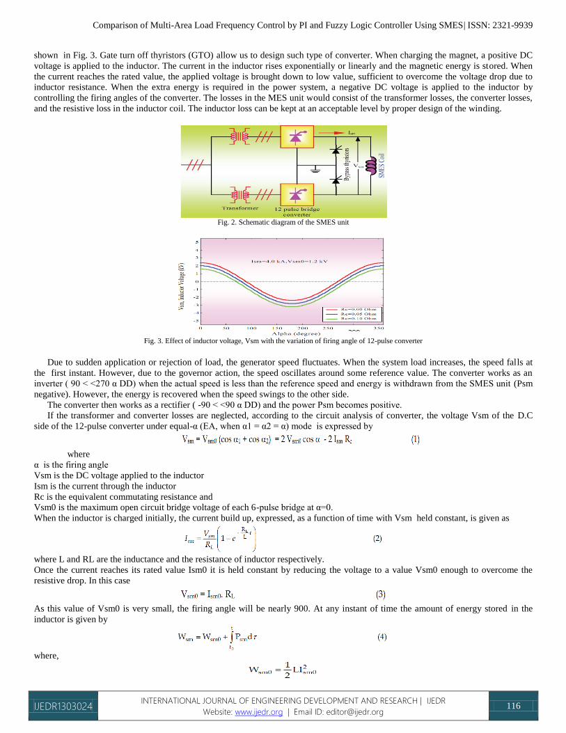
Figure 5 shows the proposed configuration of SMES units in a two-area power system [Mufti et al., 2007]. Two areas are
connected by a weak tie-line. When there is sudden rise in power demand in a control area, the stored energy is almost immediately
released by the SMES through its power conversion system (PCS). As the governor control mechanism starts working to set the
power system to the new equilibrium condition, the SMES coil stores energy back to its nominal level. Similar action happens when
there is a sudden decrease in load demand.
Basically, the operation speed of governor-turbine system is slow compared with that of the excitation system. As a result,
fluctuations in terminal voltage can be corrected by the excitation system very quickly, but fluctuations in generated power or
frequency are corrected slowly. Since load frequency control is primarily concerned with the real power/frequency behavior, the
Comparison of Multi-Area Load Frequency Control by PI and Fuzzy Logic Controller Using SMES| ISSN: 2321-9939
IJEDR1303024 INTERNATIONAL JOURNAL OF ENGINEERING DEVELOPMENT AND RESEARCH | IJEDR
Website: www.ijedr.org | Email ID: [email protected] 118
excitation system model will not be required in the approximated analysis [Mufti et al., 2007 & Sheikh et al., 2008]. This important
simplification paves the way for constructing the simulation model shown in Fig. 6.
Fig. 5. Configuration of SMES in a two-area power system
The basic objective of the supplementary control is to restore balance between each area load and generation for a load
disturbance. This is met when the control action maintains the frequency and the tie-line power interchange at the scheduled values.
The supplementary controller with integral gain KIi is therefore made to act on area control error (ACE), which is a signal obtaind
from tie-line power flow deviation added to frequency deviation weighted by a bias factor β.
where the suffix i refer to the control area and j refer to the number of generator. All parameters are same as those used in [Sheikh et
al., 2008]
Fig. 6. Digital simulation model for the two-area power system
V. OPTIMIZATION OF INTEGRAL GAIN, KI AND FREQUENCY BIAS FACTORS, Β
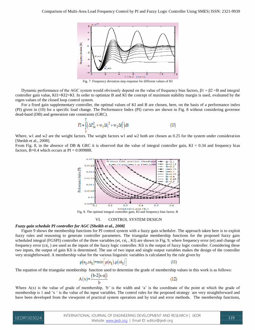
Figure 7 shows the frequency deviations for different values of KI for a specific load change. It is observed that a higher value of
KI results in reduction of maximum deviation of the system frequency but the system oscillates for longer times. Decreasing the value
of KI yields comparatively higher maximum frequency deviation at the beginning but provides very good damping in the later cycles.
These initiate a variable KI, which can be determined from the frequency error and its derivative. Obviously, higher values of KI are
needed at the initial stage and then it should be changed gradually depending on the system frequency changes.
Comparison of Multi-Area Load Frequency Control by PI and Fuzzy Logic Controller Using SMES| ISSN: 2321-9939
IJEDR1303024 INTERNATIONAL JOURNAL OF ENGINEERING DEVELOPMENT AND RESEARCH | IJEDR
Website: www.ijedr.org | Email ID: [email protected] 119
Fig. 7. Frequency deviation step response for different values of KI
Dynamic performance of the AGC system would obviously depend on the value of frequency bias factors, β1 = β2 =B and integral
controller gain value, KI1=KI2=KI. In order to optimize B and KI the concept of maximum stability margin is used, evaluated by the
eigen-values of the closed loop control system.
For a fixed gain supplementary controller, the optimal values of KI and B are chosen, here, on the basis of a performance index
(PI) given in (10) for a specific load change. The Performance Index (PI) curves are shown in Fig. 8 without considering governor
dead-band (DB) and generation rate constraints (GRC).
Where, w1 and w2 are the weight factors. The weight factors w1 and w2 both are chosen as 0.25 for the system under consideration
[Sheikh et al., 2008].
From Fig. 8, in the absence of DB & GRC it is observed that the value of integral controller gain, KI = 0.34 and frequency bias
factors, B=0.4 which occurs at PI = 0.009888.
Fig. 8. The optimal integral controller gain, KI and frequency bias factor, B
VI. CONTROL SYSTEM DESIGN
Fuzzy gain schedule PI controller for AGC [Sheikh et al., 2008]
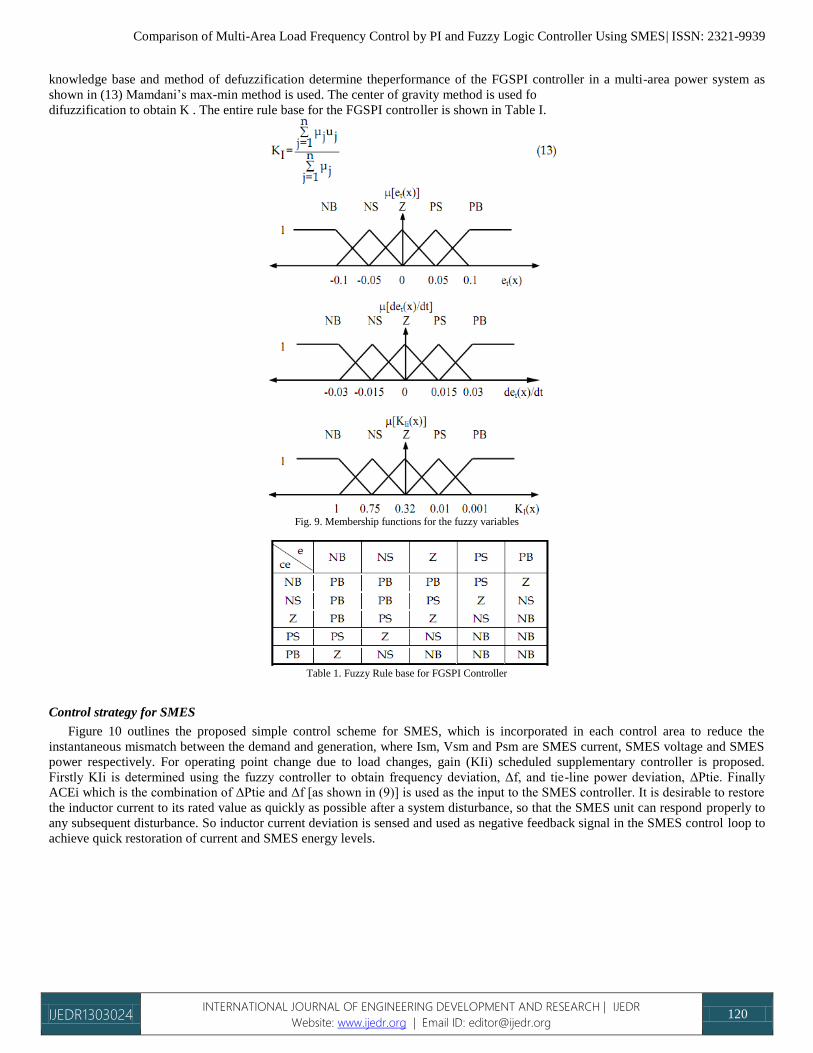
Figure 9 shows the membership functions for PI control system with a fuzzy gain scheduler. The approach taken here is to exploit
fuzzy rules and reasoning to generate controller parameters. The triangular membership functions for the proposed fuzzy gain
scheduled integral (FGSPI) controller of the three variables (et, c ̇ , KI) are shown in Fig. 9, where frequency error (et) and change of
frequency error (c ̇ ) are used as the inputs of the fuzzy logic controller. KIi is the output of fuzzy logic controller. Considering these
two inputs, the output of gain KIi is determined. The use of two input and single output variables makes the design of the controller
very straightforward. A membership value for the various linguistic variables is calculated by the rule given by
The equation of the triangular membership function used to determine the grade of membership values in this work is as follows:
Where A(x) is the value of grade of membership, ‘b’ is the width and ‘a’ is the coordinate of the point at which the grade of
membership is 1 and ‘x ‘ is the value of the input variables. The control rules for the proposed strategy are very straightforward and
have been developed from the viewpoint of practical system operation and by trial and error methods. The membership functions,
Comparison of Multi-Area Load Frequency Control by PI and Fuzzy Logic Controller Using SMES| ISSN: 2321-9939
IJEDR1303024 INTERNATIONAL JOURNAL OF ENGINEERING DEVELOPMENT AND RESEARCH | IJEDR
Website: www.ijedr.org | Email ID: [email protected] 120
knowledge base and method of defuzzification determine theperformance of the FGSPI controller in a multi-area power system as
shown in (13) Mamdani’s max-min method is used. The center of gravity method is used fo
difuzzification to obtain K . The entire rule base for the FGSPI controller is shown in Table I.
Fig. 9. Membership functions for the fuzzy variables
Table 1. Fuzzy Rule base for FGSPI Controller
Control strategy for SMES
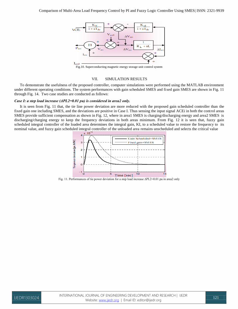
Figure 10 outlines the proposed simple control scheme for SMES, which is incorporated in each control area to reduce the
instantaneous mismatch between the demand and generation, where Ism, Vsm and Psm are SMES current, SMES voltage and SMES
power respectively. For operating point change due to load changes, gain (KIi) scheduled supplementary controller is proposed.
Firstly KIi is determined using the fuzzy controller to obtain frequency deviation, Δf, and tie-line power deviation, ΔPtie. Finally
ACEi which is the combination of ΔPtie and Δf [as shown in (9)] is used as the input to the SMES controller. It is desirable to restore
the inductor current to its rated value as quickly as possible after a system disturbance, so that the SMES unit can respond properly to
any subsequent disturbance. So inductor current deviation is sensed and used as negative feedback signal in the SMES control loop to
achieve quick restoration of current and SMES energy levels.
Comparison of Multi-Area Load Frequency Control by PI and Fuzzy Logic Controller Using SMES| ISSN: 2321-9939
IJEDR1303024 INTERNATIONAL JOURNAL OF ENGINEERING DEVELOPMENT AND RESEARCH | IJEDR
Website: www.ijedr.org | Email ID: [email protected] 121
Fig.10. Superconducting magnetic energy storage unit control system
VII. SIMULATION RESULTS
To demonstrate the usefulness of the proposed controller, computer simulations were performed using the MATLAB environment
under different operating conditions. The system performances with gain scheduled SMES and fixed gain SMES are shown in Fig. 11
through Fig. 14. Two case studies are conducted as follows:
Case I: a step load increase (ΔPL2=0.01 pu) is considered in area2 only.
It is seen from Fig. 11 that, the tie line power deviation are more reduced with the proposed gain scheduled controller than the
fixed gain one including SMES, and the deviations are positive in Case I. Thus sensing the input signal ACEi in both the control areas
SMES provide sufficient compensation as shown in Fig. 12, where in area1 SMES is charging/discharging energy and area2 SMES is
discharging/charging energy to keep the frequency deviations in both areas minimum. From Fig. 12 it is seen that, fuzzy gain
scheduled integral controller of the loaded area determines the integral gain, KI, to a scheduled value to restore the frequency to its
nominal value, and fuzzy gain scheduled integral controller of the unloaded area remains unscheduled and selects the critical value
Fig. 11. Performances of tie power deviation for a step load increase ∆PL2=0.01 pu in area2 only
Comparison of Multi-Area Load Frequency Control by PI and Fuzzy Logic Controller Using SMES| ISSN: 2321-9939
IJEDR1303024 INTERNATIONAL JOURNAL OF ENGINEERING DEVELOPMENT AND RESEARCH | IJEDR
Website: www.ijedr.org | Email ID: [email protected] 122
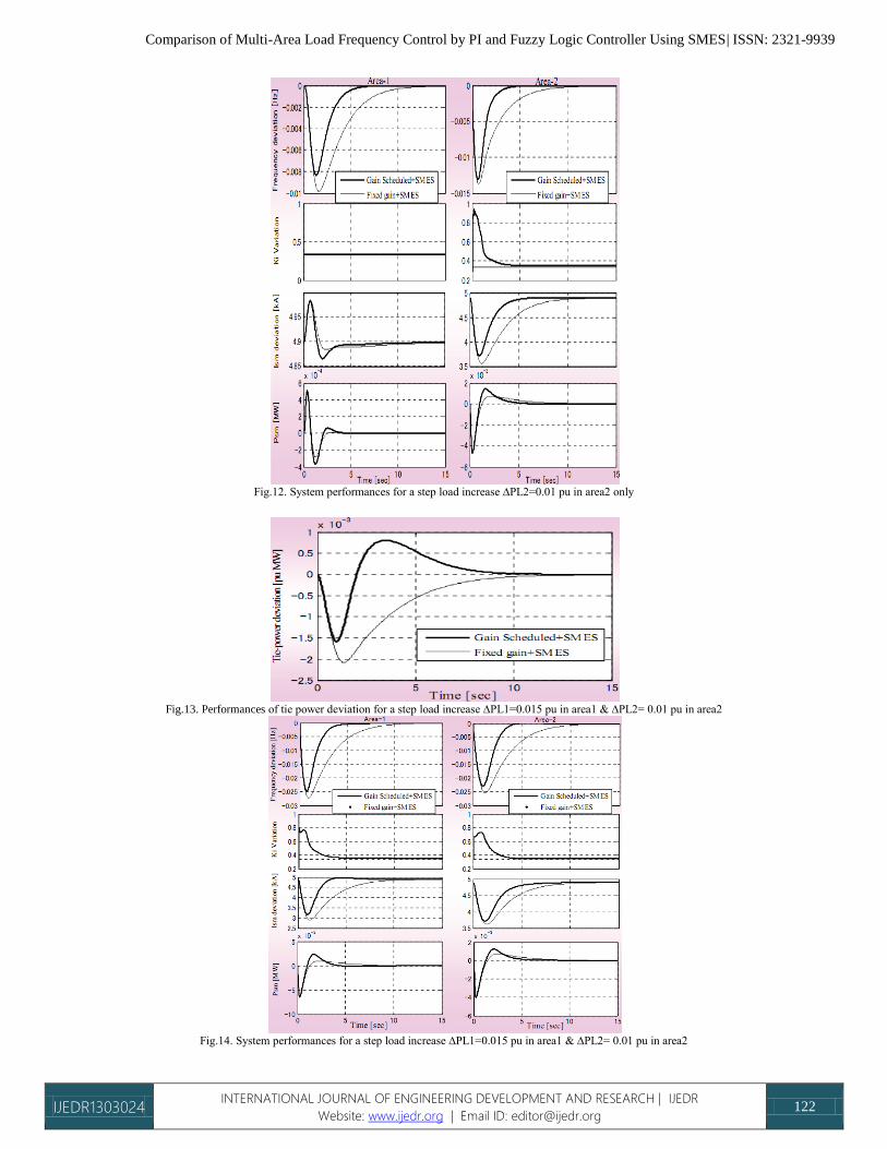
Fig.12. System performances for a step load increase ∆PL2=0.01 pu in area2 only
Fig.13. Performances of tie power deviation for a step load increase ∆PL1=0.015 pu in area1 & ∆PL2= 0.01 pu in area2
Fig.14. System performances for a step load increase ∆PL1=0.015 pu in area1 & ∆PL2= 0.01 pu in area2
Comparison of Multi-Area Load Frequency Control by PI and Fuzzy Logic Controller Using SMES| ISSN: 2321-9939
IJEDR1303024 INTERNATIONAL JOURNAL OF ENGINEERING DEVELOPMENT AND RESEARCH | IJEDR
Website: www.ijedr.org | Email ID: [email protected] 123
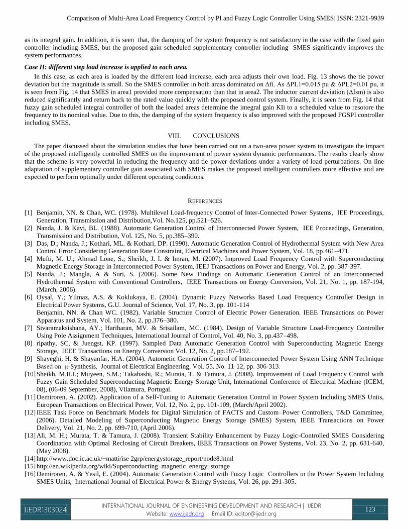
as its integral gain. In addition, it is seen that, the damping of the system frequency is not satisfactory in the case with the fixed gain
controller including SMES, but the proposed gain scheduled supplementary controller including SMES significantly improves the
system performances.
Case II: different step load increase is applied to each area.
In this case, as each area is loaded by the different load increase, each area adjusts their own load. Fig. 13 shows the tie power
deviation but the magnitude is small. So the SMES controller in both areas dominated on Δfi. As ΔPL1=0.015 pu & ΔPL2=0.01 pu, it
is seen from Fig. 14 that SMES in area1 provided more compensation than that in area2. The inductor current deviation (ΔIsm) is also
reduced significantly and return back to the rated value quickly with the proposed control system. Finally, it is seen from Fig. 14 that
fuzzy gain scheduled integral controller of both the loaded areas determine the integral gain KIi to a scheduled value to resotore the
frequency to its nominal value. Due to this, the damping of the system frequency is also improved with the proposed FGSPI controller
including SMES.
VIII. CONCLUSIONS
The paper discussed about the simulation studies that have been carried out on a two-area power system to investigate the impact
of the proposed intelligently controlled SMES on the improvement of power system dynamic performances. The results clearly show
that the scheme is very powerful in reducing the frequency and tie-power deviations under a variety of load perturbations. On-line
adaptation of supplementary controller gain associated with SMES makes the proposed intelligent controllers more effective and are
expected to perform optimally under different operating conditions.
REFERENCES
[1] Benjamin, NN. & Chan, WC. (1978). Multilevel Load-frequency Control of Inter-Connected Power Systems, IEE Proceedings,
Generation, Transmission and Distribution,Vol. No.125, pp.521–526.
[2] Nanda, J. & Kavi, BL. (1988). Automatic Generation Control of Interconnected Power System, IEE Proceedings, Generation,
Transmission and Distribution, Vol. 125, No. 5, pp.385–390.
[3] Das, D.; Nanda, J.; Kothari, ML. & Kothari, DP. (1990). Automatic Generation Control of Hydrothermal System with New Area
Control Error Considering Generation Rate Constraint, Electrical Machines and Power System, Vol. 18, pp.461–471.
[4] Mufti, M. U.; Ahmad Lone, S.; Sheikh, J. I. & Imran, M. (2007). Improved Load Frequency Control with Superconducting
Magnetic Energy Storage in Interconnected Power System, IEEJ Transactions on Power and Energy, Vol. 2, pp. 387-397.
[5] Nanda, J.; Mangla, A & Suri, S. (2006). Some New Findings on Automatic Generation Control of an Interconnected
Hydrothermal System with Conventional Controllers, IEEE Transactions on Energy Conversion, Vol. 21, No. 1, pp. 187-194,
(March, 2006).
[6] Oysal, Y.; Yilmaz, A.S. & Koklukaya, E. (2004). Dynamic Fuzzy Networks Based Load Frequency Controller Design in
Electrical Power Systems, G.U. Journal of Science, Vol. 17, No. 3, pp. 101-114
Benjamin, NN. & Chan WC. (1982). Variable Structure Control of Electric Power Generation. IEEE Transactions on Power
Apparatus and System, Vol. 101, No. 2, pp.376–380.
[7] Sivaramaksishana, AY.; Hariharan, MV. & Srisailam, MC. (1984). Design of Variable Structure Load-Frequency Controller
Using Pole Assignment Techniques, International Journal of Control, Vol. 40, No. 3, pp.437–498.
[8] ripathy, SC, & Juengst, KP. (1997). Sampled Data Automatic Generation Control with Superconducting Magnetic Energy
Storage, IEEE Transactions on Energy Conversion Vol. 12, No. 2, pp.187–192.
[9] Shayeghi, H. & Shayanfar, H.A. (2004). Autometic Generation Control of Interconnected Power System Using ANN Technique
Based on μ-Synthesis, Journal of Electrical Engineering, Vol. 55, No. 11-12, pp. 306-313.
[10] Sheikh, M.R.I.; Muyeen, S.M.; Takahashi, R.; Murata, T. & Tamura, J. (2008). Improvement of Load Frequency Control with
Fuzzy Gain Scheduled Superconducting Magnetic Energy Storage Unit, International Conference of Electrical Machine (ICEM,
08), (06-09 September, 2008), Vilamura, Portugal.
[11] Demiroren, A. (2002). Application of a Self-Tuning to Automatic Generation Control in Power System Including SMES Units,
European Transactions on Electrical Power, Vol. 12, No. 2, pp. 101-109, (March/April 2002).
[12] IEEE Task Force on Benchmark Models for Digital Simulation of FACTS and Custom–Power Controllers, T&D Committee,
(2006). Detailed Modeling of Superconducting Magnetic Energy Storage (SMES) System, IEEE Transactions on Power
Delivery, Vol. 21, No. 2, pp. 699-710, (April 2006).
[13] Ali, M. H.; Murata, T. & Tamura, J. (2008). Transient Stability Enhancement by Fuzzy Logic-Controlled SMES Considering
Coordination with Optimal Reclosing of Circuit Breakers, IEEE Transactions on Power Systems, Vol. 23, No. 2, pp. 631-640,
(May 2008).
[14] http://www.doc.ic.ac.uk/~matti/ise 2grp/energystorage_report/node8.html
[15] http://en.wikipedia.org/wiki/Superconducting_magnetic_energy_storage
[16] Demiroren, A. & Yesil, E. (2004). Automatic Generation Control with Fuzzy Logic Controllers in the Power System Including
SMES Units, International Journal of Electrical Power & Energy Systems, Vol. 26, pp. 291-305.

Comparison of Multi-Area Load Frequency Control by PI and Fuzzy Logic Controller Using SMES| ISSN: 2321-9939
IJEDR1303024 INTERNATIONAL JOURNAL OF ENGINEERING DEVELOPMENT AND RESEARCH | IJEDR
Website: www.ijedr.org | Email ID: [email protected] 124
[17] Abraham, R.J.; Das, D. & Patra, A. (2008). AGC Study of a Hydrothermal System with SMES and TCPS, European Transactions
on Electrical Power, DOI: 10.1002/etep.235
[18] Wu, C. J. & Lee, Y. S. (1991). Application of Superconducting Magnetic Energy Storage to Improve the Damping of
Synchronous Generator, IEEE Transactions on Energy Conversion, Vol. 6, No. 4, pp. 573-578, (December 1991).
[19] Banerjee, S.; Chatterjee, J. K. & Tripathy, S. C. (1990). Application of Magnetic Energy Storage Unit as Load Frequency
Stabilizer, IEEE Transactions on Energy Conversion, Vol. 5, No. 1, pp. 46-51, (March 1990).


![PI CONTROLLER BASED SHUNT CONNECTED THREE ...realize the potential and feasibility of PI controller [17], [18]. (a) Current Wave of Current Controller (b) Current Controller Waveform](https://img.pdfslide.us/doc/110x75/604b4b4b953f6a233834072a/pi-controller-based-shunt-connected-three-realize-the-potential-and-feasibility.jpg)


![Pi Pid Controller[eBook.veyq.Ir]](https://img.pdfslide.us/doc/110x75/577cd44b1a28ab9e789821ba/pi-pid-controllerebookveyqir.jpg)