Embed Size (px)
Citation preview

COMPARISON OF LOSSLESS COMPRESSION MODELS
by
ANAHIT HOVHANNISYAN, B.S.
A THESIS
IN
ELECTRICAL ENGINEERING
Submitted to the Graduate Faculty of Texas Tech University in
Partial Fulfillment of the Requirements for
the Degree of
MASTER OF SCIENCE
IN
ELECTRICAL ENGINEERING
Approved
Accepted
August, 1999

ACKNOWLEDGMENTS
I would like to thank my graduate adviser. Dr. Mitra. for her support and encouragement
during my graduate research. I appreciate the help and assistance of m\ colleagues from
the Computer Vision and Image Analysis Lab. 1 also wish to thank Dr. Wunsch. Dr.
Maquzi, and Dr. Lakhani for serving on my graduate committee and thesis defense.

TABLI OF COMI-NIS
ACKXOWLHDCil-MHNTS ii
ABSTRACT v
LIST OF TABLES vi
LIST OF FIGURES vii
CHAPTER
I. INTRODUCTION TO LOSSLESS IMAGE COMPESSION 1
II. HUFFMAN CODING 6
2.1 Introduction to Huffman Compression 6
2.2 Huffman Code Construction 7
2.3 Huffman Decoder 11
2.4 Modified Huffman using the deri\ ati\ e image 11
III. ARITHMETIC CODING 15
3.1 Introduction to Arithmetic Coding 1 ^
3.2 Arithmetic Code Construction 16
IV. COMPARISON OF TWO BINAR^• IMAGE CODING TECIlNiQULS 20
4.1 Run Length Encoding 20
4.2 Introduction to DMC 22
4.3 .\dapti\ e Coding 23
4 4 Introduction to the Guazzo"s Coding Algorithm 26
4.5 Guazzo Encoding Applied to the Markox Model 27
I I I

V. TESTS AND RESULTS 28
5.1 Comparison of DMC with RLE for binary images 31
VI. CONCLUSIONS 34
REFERENCES 35
APPENDIX
A. C++ IMPLEMENTATION OF HUFFMAN CODER .AND DECODER 37
B. ANCl C IMPLEMENTATION OF RUN LENGTH ENCODER AND DECODER 47
i \

ABSTR.ACT
With the development of multimedia and digital imaging there is a need to reduce the
cost of storage and transmission of information. The cost reduction translates into
reducing the amount of data that represent the information. This thesis investigates the
performance of se\ eral lossless compression algorithms widely used for image coding.
The first three chapters describe these algorithms in detail, as well as gi\e examples of
well-known data compression algorithms such as Huffman. Arithmetic. D\ namic Marko\
Coding, and Run Length Encoding. Finally, the relati\e performances of the listed
algorithms are compared. The thesis also includes C— and A.\SI C implementations of
the Huffman and RLE algorithms respectively.

LIST OF TABLES
2.1 Huffman tree construction steps 8
2.2 Huffman codes 10
2.3 Probabilities of the gra> -level source symbols 12
2.4 Probabilities of the difference source s\ mbols 13
3.1 Probabilities of symbols 17
3.2 The ranges of the encoded symbols 17
5.1 The compression results of original gray-scale images b\ Arithmetic Encoder.. .29
5.2 The compression results of original gray-scale images by Huffman Encoder 29
5.3 RLE compression results 32
5.4 DMC compression results 33
VI

LIST OF FIGURES
1.1 Standard compression technique model 3
1.2 Lossless compression scheme 1 5
2.1 Huffman tree for Tf, z, z. z, z z, /.,, /-source alphabet >
2.2 Lena Image a) image with histogram, b) Deri\ati\c of image with histogram... 14
3.1 Representation of arithmetic coding process 18
4.1 A binarx image (a) Direct storage, (b) Run length 21
4.2 State Transition Diagram 27
5.1 Compression scheme for the first set of the results 2(X
5.2 Retinal image and its histogram 30
5.3 Original Lena image a)image histogram . b) Binarazed image with histogram..31
5.4 Binary images a)Binarized \ersion of the original Lena image.
b) binarized \ersion of the brain slice image. c)binarized \ersion of the retinal
imaue 32
\ i i

CHAPTER 1
INTRODUCTION TO IMAGE COMPRESSION
Image compression forms the backbone of effecti\e storage for many
applications. Compression of images involves taking advantage of the redundancy of data
present within an image. A fundamental goal of data compression is to reduce the bit rate
for transmission and storage, while maintaining an acceptable fidelity of image quality.
Information in its \arious forms needs to be stored and transmitted in an efficient manner
for any application. The demand for de\ eloping algorithms to efficiently store or transmit
large volumes of information is increasing tremendously. Specificalh. in the field of
Digital Image Processing the need to store and transmit digital images is una\oidable.
The large number of bits required to represent each pixel in a digital image and
the large number of pixels present in each image pose a critical problem. Image
Compression, which is the field dealing with efficient coding of image data, aims at
reducing the number of bits required to represent an image. This is usually done b\
exploiting the psycho-\isual sensiti\ity as well as statistical redundancies in the image
data.
There are many approaches to image compression, but they can be characterized
broadh as predictive and transform coding. Each of these can be designed to be either
loss} or lossless. Lossless compression refers to compression without losing an\
information. The decoded pixel values will be the same as encoded pixel \alues. Any
lossy compression technique invoh es quantization of the data. This quantization process

is where loss of information occurs. Lossy compression has the advantage of reaching
much higher compression ratios (CR).
^ Number of bits for oriuinal imaue , , CR = — : ^ ^ ^—- (1.1)
Number ot bits tor compressed image
Howe\er. in many applications it is unacceptable to ha\e losses. This means that the
decompressed image needs to be an exact reproduction of the original uncompressed
image. The amount of information contained in the s\ mbols encoded can be measured
quantitati\ eh . The entrop) is the amount of information in r-ar\' units per symbol of a
source, where J is the number of different s\ mbols and P(a^) is the probability of symbol a ^.
entropy = - ^P(a^ ) l og , P{a^) (1.2)
When the base of the logarithm is 2. the entropy is measured in bits per pixel. The
entropy of the source is the theoretical limit of the least number of bits required to code
each s\'mbol on average [3]. Lossless coding is usualh referred to as entropy coding

The stages of lossy and lossless compression techniques are shown in the Figure 1.1.
Image Bit stream
Entropy Coding > Channel
(a)
Decoder
Input image
Compressed image
Forward transform
Symbol decoder
^ Quantizer Symbol encoder
Inverse transform
Compressed image
j ^ Reconstructed image
(b)
Figure 1.1 Standard compression technique model, (a) Lossless, (b) Lossy
Any image compression technique can be modeled to be either a two-stage or a three-
stage process. In general, a lossy compression technique consists of signal
transformation, quantization, and lossless coding as shown in Figure 1.1 (b). The first
stage of signal mapping in a lossy compression technique converts an image from its
original form to a different domain, usually a transform domain, in which the signal is
decorrelated for the second stage. This does not cause any information loss unless some
form of truncation is used. In other words, the objective of this stage is to convert the
image into a form such that quantization performance can be optimized. The current
standard of still image compression, adapted by the Joint Photographic Experts Group

(JPEG), uses the discrete cosine transform (DCT) on each 8 x 8 block of an image.
Recent research uses a wavelet transformation on the entire image to a\oid the blocking
artifacts generated b\ JPEG and to take ad\antage of subband coding.
The second-stage in\ohes the process of quantizing the transformed image,
usually employing scalar or \ector quantization techniques. This is the stage where loss
of information occurs. Since this is the stage where most of compression is achieved and
loss of information occurs, it is the central stage of any compression technique. The third
stage invohes entropy coding that reduces the redundancy in data. Usually a combined
Huffman and Run-length coding, as well as arithmetic encoding techniques are used for
this purpose.
The goal of the proposed research is to investigate the performance of recently
developed lossless compression techniques based on difference coding models. This
thesis presents results of lossless encoding and decoding of gray le\ el as well as binary
images. Two different compression schemes - namely Huffman and Arithmetic - are
employed for gray level image. Since DMC is designed for coding binary messages, the
performance of DMC is compared with that of Run Length Encoding for binary images
(Figure 1.2).

Huffman Encoder
Image Arithmetic Encoder
Huffman Decoder
Channel
Dynamic Markov Encoder
Run Length Encoding
Arithmetic Decoder
Reconstructed Imaue
Dxnamic ^ Markov Decoder
Run Length Decoding
Figure 1.2. Lossless compression scheme I
This master's thesis is organized as follows. Chapter II describes the Huffman
compression algorithm and contains an example that shows how the actual compression
is performed on the source message. Chapter III and Chapter IV contain description of
Arithmetic, Dynamic Markov as well as Run Length Encoding schemes respectively.
Chapter IV also talks about advantages of the Dynamic Markov encoding algorithm over
the standard Huffman encoding scheme. Chapter IV includes the test results. Finally
Chapter V gives a brief description of the conclusions and the scope for future work.
CHAPTER II
HUFFMAN ENCODING ALGORITHM
2.1 Introduction to Huffman Compression
Huffman coding is a classical data compression technique. It has been used in
various compression applications, including image compression. It is a simple, yet
elegant, compression technique that can supplement other compression algorithms. It
utilizes the statistical property of alphabets in the source stream, and then produces
respective codes for these alphabets. These codes are of variable code length using
integral number of bits. The codes for alphabets having higher probability of occurrence
are shorter than those codes for alphabets having lower probability. This simple idea
causes a reduction in the a\erage code length, and thus the overall size of compressed
data is smaller than the original.
The compression process is based on building a binary tree that holds all
alphabets in the source at its leaf nodes, and with their corresponding alphabets'
probabilities at the side. The tree is built b\ going through the following steps:
1. Each of the alphabets is laid out as leaf node w hich is going to be connected. The
alphabets are ranked according to their weights, which represents the probabilities of
their occurrences in the source.
2. Two nodes with the lowest weights are combined to form a new node, which is a
parent node of these two nodes. This parent node is then considered as a
representative of the two nodes with a weight equal to the sum of the weights of two

nodes. Moreo\er. one of the children is assimied a "0" and the other is assiizned a
3. Nodes are then successively combined as above until a binary tree containing all of
nodes is created.
4. The code representing a given alphabet can be determined by going from the root of
the tree to the leaf node representing the alphabet. The accumulation of symbol "0"
and "1" is the code of that alphabet.
B\ using this procedure, the alphabets are naturally assigned codes that reflect
probabilit\ distribution. Highh probable alphabets will be gi\en short codes, and
improbable alphabets will ha\e long codes. Therefore, the average code length will be
reduced. If the statistic of alphabets is \ er\ biased to some particular alphabets, the
reduction will be \erv si2nificant.
2.2 Huffman Code Construction
The idea behind Huffman coding is simph to use shorter bit patterns for more
common s\mboIs. This idea can be made quantitati\e b\ considering the concept of
entrop\.
Suppose, that the input alphabet has N characters, and that these occur in the input string
with respective probabilities P, , i = 1 N^,,. so that
;=l

Then, the fundamental theorem of information theory says that the string consisting of
independently random sequences of these characters require, on the average, at least
entropy = - ^ / > log, / (2.2)
bits per character [4].
For the case of equiprobable characters with all P = one can easilv see that N ch
entropy = log, A ,
where N ,, is the total number of characters in the sequence
(2.3)
which shows that no compression at all is possible. Any other set of P,'s results in
smaller entropy estimation, allow ing some useful compression.
The Huffman encoding can be \i\idly demonstrated on example. Lets consider
an input image whose source alphabet consist of 8 symbols-Q Z, Z, Z. Z^ Z, Z^ Z,
with respective probabilities 0.4. 0.08, 0.08. 0.2. 0.12. 0.08. 0.03. 0.01 (Table 2.1).
Table 2.1 Huffman tree construction steps
Level 1 Symbol Prob zO 0.4 z1 0.08 z2 0.08 z3 0.2 z4 0.12 z5 0.08 z6 0.03 z7 0.01
Level 2
Symbol Prob zO 0.4 z1 0.08 z2 0.08 z3 0.2 z4 0.12 z5 0.08 A 0.04
Level 3
Symbol Prob zO 0.4 z1 0.08 z2 0.08 z3 0.2 z4 0.12 B 0.12
Level 4 Symbol Prob zO 0.4 C 0.16 z3 0.2 z4 0.12 B 0.12
Level 5
Symbol Prob zO 0.4 C 0.16 z3 0.2 D 0.24
Level 6 Symbol Prob zO 0.4 E 0.36 D 0.24
Level 7 Symbol Prob zO 0.4 F 0.6

For the binary tree construction we should first go through the steps 1-3
mentioned above (Figure 2.1).
Symbol
Prob
Z0 Z1 z2 z3 z4 z5 z6 z7
0.4 0.08 0.08 0.2 0.12 0.08 0.03 0.01
+ - - + +
1 1 0 1 1 1
+
1
I I I + - + - +
1 I 0 + +
0
I • +
0 • + - -
I • —-
1
• +
0
I Root
I •+
0
0
Figure 2.1 Huffman tree for "o z, z, z, z z, z , z, source alphabet
The branches of the tree are labeled 0 on right side and 1 on left side. In order to read the
code of the symbol one should start from the root and travel to the leaf that represents
each level, reading off the bits that make up the code for that level (Table 2.2).

Table 2.2 Huffman codes
Symbol
^0
z,
Z2
Z3
Z4
Z5
Z6
Z7
Huffman Code 1
0111
0110
010
001
0001
00001
00000
It can be easily noticed that more frequent symbols are coded by fewer bits. The Huffman
code assigned to each symbol is unique. The entropy of a message composed of the
symbols above is:
entropy = -y\P,\og,P, = -[0.4*log2(0.4) + 3*{ 0.08*log2(0.08) } +
0.2*log2(0.2) + 0.12*log2(0.12) + 0.03*Iog2(0.03) + 0.1*log2(0.01) ] = -[ 0.529 + 0.874
+ 0.464 + 0.37 + 0.152 + 0.066 ] = 2.45 bits/symbol.
This is the theoretical limit of the possible compression. No source code can
achieve better.
The average length of the Huffman code words is:
i.-\
4„,=-Z'('•*)/'.('•*) (2.4) ^=0
where r^ is a discrete random variable in the interval [0, 1] represents the gray levels of
an image and each r occurs with pobability p,X^'k) [ 1-
L „. =1*0.4 + 3*4*0.08 + 3*0.2 + 3*0.12 + 5*0.03 + 5*0.01= 2.52 bits/symbol
10

which is not far off the optimum.
2.3 Huffman Decoder
The task of decoder is to reconstruct the original source message from the bit
stream. In order to do this Huffman decoder should possess the information about the
source alphabet with frequency of occurrence of each source s\mbol along with the
encoded bit stream. Based on the probabilit> of occurrence of each s\ mbol the decoder
will construct an identical tree which was constructed by the encoder [5]. Once the tree is
constructed, the decoder will take an abstracted stream of bits and simulates walking
down the tree. The Huffman code is uniquely decodable. For my example, suppose a
decoder receives, from the channel, the bit stream:
0110100001
Examine this from the left. Neither 0, 01. nor 011 correspond to any code in Table2.2 .
But, 0110 corresponds to z . The next bit is 1. which corresponds unambiguously to ^ .
etc.
0110 1 00001
z2 zO z6
2.4 Modified Huffman using the derivative image
The Huffman compression technique was applied to the derivative of the original
gray scale images. The derivative image is constructed by replicating the first column of

the original image and using the arithmetic difference between adjacent columns for the
remaining elements [3].
Example:
Consider we ha\e original gra\ scale 8 by 8 image
22 22 22 96 170 245 245 245 22 22 22 96 170 245 245 245 22 22 22 96 170 245 245 245 22 22 22 96 170 245 245 245 22 22 22 96 170 245 245 245 22 22 22 96 170 245 245 245 22 22 22 96 170 245 245 245 22 22 22 96 170 245 245 245
Calculation of probabilities of the gra\ level source symbols is demonstrated in the Table
2.3.
Table 2.3. Probabilities of the grav level source svmbols
Gray level Count
22
96
170
24
8
Probabilit>
2464
8'64
8 8 64
245 24 24 64
The first-order entropy estimate can be calculated through formula (1.2)
P=-(24/64*log2(24/64)+8/64*log2(8 64)^8 64*log2(8 64)^24'64*log2(24 64))=l.811
Now I calculate the deri\ati\e of the original image.
12

22 0 0 22 0 0 22 0 0 22 0 0 22 0 0 22 0 0 22 0 0 22 0 0
74 74 74 74 74 74 74 74 74 74 74 74 74 74 74 74
74 0 0 74 0 0 74 0 0 74 0 0 74 0 0 74 0 0 74 0 0 74 0 0
Calculation of probabilities of the difference source symbols is demonstrated in the Table
2.4.
Table 2.4. Probabilities of the difference source symbols
Difference symbols
22
0
74
Count
8
32
24
Probability
8/64
32/64
24/64
The first order entropy estimate is:
P=-(8/64*log2(8/64)+32/64*Iog2(32/64)+24/64*log2(24/64))= 1.4056
One can notice that the entropy estimate of the deri\ati\e image is lower than that of
original gray scale one.
The Figure 2.2 represents a original Lena image with corresponding deri\ ative.

Histogram
Max: 751 | V i | Mm 0 Avg 127
\ J ' i l l
A A J ' \
V*i
\/^^^
1 I I \:_' _ ' _ ' • • " — I Red r~ i j 'een • B .a ^ -'.iT'nani;
a)
HisloQitfn
Ma>: 4583 IbM Mm 1 4va 126
r Red r cv B '..e i< ' . . . T •i-dt-i'
b)
Figure 2.2 Lena Image a) image with histogram, b) Deri\ati\e of image with
histogram
14

CHAPTER III
ARITHMETIC CODING ALGORITHM
3.1 Introduction to Arithmetic Coding
Arithmetic coding is a relatixely new lossless s\mbol coding technique. It is \ery
similar to Huffman coding, except that it is slightly more efficient. It would appear that
Huffman coding is the perfect means of compressing data. Howe\ er. this is not the case.
The Huffman coding method is optimal if and onh if the s>mbol probabilities are integral
powers of 1/2. which rarely is the case [5].
The technique of arithmetic coding does not ha\ e this restriction, it achie\ es the same
effect as treating the message as one single unit and thus attains the theoretical entropy
bound to compression efficienc} for any source. For the Huffman algorithm, this
technique would require enumeration of e\ er\ single possible message, a daunting task
for even the least defined message.
Arithmetic coding is more complicated and difficult to implement than Huffman
coding. It works by representing a number b\ an interval of real numbers between 0 and
1. As the message becomes longer, the inter\al needed to represent it becomes smaller
and smaller, and the number of bits needed to specify that interval increases. Successive
symbols in the message reduce this interval in accordance w ith the probability of that
symbol. The more likely symbols reduce the range b\ less, and thus add fewer bits to the
message. Now that there is an efficient technique for data compression, what is needed is
a technique for building a model of the data, which can then be used with the encoder.
15

The simplest model is a fixed one. for example a table of standard letter
frequencies for English text which can be used to get letter probabilities. An
improvement on this technique is to use an adaptive model, in other words a model which
adjusts itself to the data which is being compressed as the data is compressed. The fixed
model can be converted into an adaptixe one by adjusting the s\mbol frequencies after
each new symbol is encoded, allowing the model to track the data being transmitted. The
only problem with this form of data compression is that it is very demanding of system
and compufing resources. A possible alternative to this number crunching technique is to
use look-up tables and dictionary units, or substitutional based compressors.
3.2 Arithmetic Code Construction
Arithmetic coding works b\ representing a message b\ an interval of real numbers
between 0 and 1. For the longer source messages the interval that represents it becomes
smaller and the number of bits needed to specify that interval grows. The size of the
interval is dependent on the symbols encoded and probabilities used to model the symbols.
The more likely symbols reduce the range by less than unlikely ones and hence they add
fewer bits to the message.
I would like to demonstrate how the arithmetic encoding works on the example.
This example is described in [8]. Consider a set of symbols with a fixed statistical model
comprised of five vowels and exclamation point: {a. e, i. o. u. !] Each symbol is assigned a
subinterval in the interval [0.1) based on its corresponding probabilities show n in the Table
3.1.
16

Table 3.1 Probabilities of svmbols
Symbol A
U
Probabilitv 0.2 0.3 0.1 0.2 0.1 0.1
Range [0. 0.2) [0.2. 0.5) [0.5. 0.6) [0.6. 0.8) [0.8. 0.9) [0.9.1.0)
We would like to transmit the message [eaii!j. Inifially. both encoder and
decoder know that the range is [0,1). After "e" is selected for coding, the range narrows
from [0,1) to [0.2,0.5). This range is subdivided in the same manner as the initial range.
The second symbol "a" will narrow this new range to the first one fifth of it since "a" has
been allocated [0. 0.2). This will narrow down our range to [0.2. 0.26), since the previous
range was 0.3 units long and one-fifth of that is 0.06. The symbol "i" is allocated [0.5.
0.6) which when applied to [0.2. 0.26) gives the smaller range [0.23. 0.236). This process
of narrowing the range of an encoded value for each symbol selected for coding
continues until the terminator symbol "'!" is reached. If we proceed in the same manner,
the encoded message builds up as follows in Table 3.2.
Table 3.2 The ranges of the encoded symbols
Symbol Initially E A I I !
Range [O-D [0.2. 0.5) [0.2. 0.26) [0.23, 0.236) [0.233, 0.2336) [0.23354. 0.2336)
17

The final range of the code word {eaii!} is [0.23354.0.2336). Figure 3.1 shows the ranges
expanded to full height at every stage and marked with a scale that gives the endpoints as
numbers.
After seeins
0.2^
a
0.26-1
0.2-J
0.236n
0.23-"
1
0.2336n
0
-)^^A—. 0.2336
0.23354-"
u o i
e a
Figure 3.1 Representation of arithmetic coding process
The encoded message can be uniquely decoded with any \alue in the final range.
The shortest number (with the least digits) in the specified range will represent the
encoded message. .As the length of the original message increases, the narrow er the range
becomes, and more digits will be required to store the encoded value. Since more than
one symbol is encoded with a single value, arithmetic coding is able to achie\e a bit rate
less than the first-order entropy estimate of an image.
Decoding of the message proceeds similarly to the encoding process. The initial range.
[0.1). and the symbol probabilities are known beforehand. The initial range is subdi\ided
according to the symbol probabilities. The value of 0.23355 is observed to lie in the range
[0.2. 0.5), so the decoder can immediateh deduce that the first character was "e". This
18

range is subdivided in the same manner as the initial range (Figure 3.1). The value ot
0.23355 is observed to lie in the range [0.2. 0.26) that would correspond to symbol "a".
To ensure that the decoder will not face problem of detecting the end of the message, we
should ensure that each message ands with special EOF s\mbol that is know to both
encoder and decoder. For our example "!"" will be used as a termination message. When
the decoder sees the symbol, it will stop decoding.
An adapti\e arithmetic coding model was developed and implemented by Zamora
[9. 10] and tested with various 8 bit gray scale images. The compression results can be
found in the Chapter V of this thesis.

CHAPTER IV
COMPARISON OF TWO BINARY IMAGE CODING TECHNIQUES
This chapter contains the description of two lossless compression techniques (Run
Length and Dynamic Markov Encoding) that have been applied to the binary images. The
corresponding compression results are presented and compared in the Chapter V of the
thesis.
4.1 Run Length Encoding
Run length coding (RLE) is an efficient coding technique for binary image. It
represents each row of an image or bit plane by a sequence of lengths that describe
successive runs of black and white pixels [3]. This technique was de\ eloped in 1950s and
has become a standard compression approach in facsimile coding. The concept of RLE is
to code each contiguous group of O's and I's encountered in a left to right scan of the row
bv its length and to establish a convention for determining the value of the run. The value
of the run can be established:
1. By specif) ing the \ alue of the first run of each row
2. B\ assuming that each row begins with a white run, whose run length ma\ in fact be
zero.
Run length encoding algorithm can be \'ividh demonstrated on the exapmle:
20

Consider a binary the image in Figure 4.1 (a). Run length encoding exploits the
highh repetiti\ e nature o\' the image, ft detects "runs" of the same \ alue. and codes the
image as a sequence of length-ol-run. value (Figure 4.1 (b)).
0000000000000000 16.0; 000000000 0 000000 16.0; OOOllllllllllOOO 3.0; 10.1:3.0; 0 0 0 1 1 1 1 1 1 1 1 1 1 0 0 0 3.0;I0.1;3.(); O O O l l l l l l l l l l O O O 3.0;10.1;3.(); 0000001 1 1 100000 0 6.0;4.l;6.0; 0000001 1 1 1000000 6.0;4.1;6.0; 0000001 1 1 1000000 6.0;4.1;6.0; 0000001 1 1 100000 0 6.0;4.1;6.0: 0000001 1 1 100000 0 6.0;4.1;6.0; 0000000000000000 16,0;
Figure 4.1 .\ binar\ image (a) Direct storage, (b) Run length
Each pixel is represented b\ one bit \alue that can be either one or zero. The image
represented in the Figure 4.1 (a) is 11 x 16. therefore it occupies 176 bits (22 b\tcs). If we
look at the first row of the image we notice that we ha\e 16 zeros. While encoding the
message we need to choose the length of the counter. Depending on the image si/c as well
as its pixel distribution it can \ar\ significanth. For this example, lets assume that our
counter occupies onh four bits that will reduce our message to 108 bits (13.5 b\tes). The
RLE code attached to this thesis uses two different count lengths for encoding puiposes.
One of the \ersi(ms uses 8 bits for representing a pixel counter and the other one uses only
4 bits. In the Chapter V I present the results i f the run length encoding on the \arious
binar\ images. These compression results will be compared with the results achieved b\
the Dynamic Marko\ Encoder.
21

4.2 Introduction to DMC
The Dynamic Markov Coding [13] de\ eloped b\ Cormack and Horspool attempts
to develop an algorithmic approach to combining the generation of a Markov chain Model
with Gauzzo's arithmetic coding. Their experimental results show favorable results when
compared to other similar compression techniques.
All data compression algorithms rely on a priori assumptions about the structure of
the source (initial) data. For example. Huffman coding assumes that the source data
consists of a stream of characters that are independenth and randomh selected according
to some probabilifies. Cormac and Horspool [13] assumed in their paper that the source
data is the stream of bits which is generated by a discrete parameter Markov chain model.
Such a model is general enough to describe all assumptions of Huffman and RLE (Run
length Encoding), as well as many other compression techniques.
Lempel and Ziv (inventor of LZ compression technique) together with the authors
of arithmetic coding algoritlim (Cleary and Witten [8]) make a similar assumption, that
there is an underlying Markov model for the data, in their compression techniques. The
new direction taken by G.V. Cormac and H.S. Horspool was an attempt to discover a
Markov chain model that successftilly describes the data. If such kind of model could be
constructed from the first part of a message, it could be used to predict probability of
forthcoming binary characters. The Markov chain provides an encoder with probabilities of
the next binary character being 0 or 1. After using the probabilit) estimate in a data coding
scheme, we can use the actual message character to transfer to a new state in the Markov
22

chain. The new state is being used for prediction of probability of the next message bit and
so on.
The combination of a Markov chain model (DM modeling technique) generation
with a bit oriented Guazzo arithmetic encoder is a \er\ powerftal technique of data
compression. The DMC encoder achieves approximately the same results that CIear\ and
Witten encoding algorithm achieves, but the DMC method can be (in some cases) simpler,
faster, may require less storage, and consumes less CPU time.
As was mentioned above the combination of Dynamic Markov modeling technique
and bit oriented arithmetic encoding has given comparably good results, although DM
modeling can also be combined with other compression algorithms.
Cormac and Horspool could not find mathematical proof that the dynamicalh
changing model converges to the true model of the data. They state that such a proof is
unlikely in any case because the number of states in the model grows without limits. The
modeling technique has been judged, so far. only on the basis that it works [13].
4.3. Adaptive Coding
There are two ways to implement the coding techniques. One of them is one-pass
and the second is two-pass. Data compression has traditionally been implemented as a two
pass technique. The initial pass is done through the original set of data (source message) to
discover its characteristics. Then, the obtained knowledge is used in order to implement
the second stage, namely the second pass, for compressing the data. In Huffman coding, the
first pass would count the frequencies of occurrence of each character. The Huffman codes
23

can be constructed before the second pass performs encoding. In order to ensure that the
compressed data can be decompressed, either a fixed coding scheme must be used or else
details of the compression scheme must be included w ith the compressed stream of the
data.
As was mentioned above, all the techniques either use fixed statistics or make two
passes over the message. Fixed statistics techniques are called "static" and the two pass
techniques are called "semi-adaptive". Generally, both techniques are unsatisfactory for
general purpose data compression. Static techniques can not adapt to unexpected data, and
semi adaptive techniques require two passes, making them unsuitable for communication
lines.
Adaptive techniques combine the best of static and semi-adaptive techniques by
making a single sequential pass over the message, adapting as they go. At each step the
next piece of the message is transmitted using a code constructed from the history. This is
possible because both the transmitter and receiver have access to the history and can
independently construct the code used to transmit the next piece of the message. Several
theorems have shown that adaptive compression techniques are superior to those of semi-
adaptive [11].
The DMC algorithm uses a "non-traditional" one-pass adaptive encoding scheme.
One-pass implementations are preferable from the several points of view. First, they do not
require the entire message to be saved in on-line computer memory before encoding can
take place. Second, one-pass schemes can be used for real time transmission.
24

The basic idea of an adaptive coding algorithm is that the encoding scheme changes
dramatically while the message is being encoded. The coding scheme used for the k-th
character of a message is based on the characteristics of the preceding k-1 characters in the
message.
For example, adaptive versions of Huffman coding have been proposed and implemented.
In practice, adaptive Huffman coding achieves data compression that differs insignificantl}
from conventional two-pass Huffman coding at the expense of considerably more
computational effort.
Experimentally, it has been shown that the Guazzo coding algorithm is eminently
suitable for use in adaptive coding schemes [16]. The only aspect of the algorithm that
changes dynamically is the source of probability estimates for the message characters. At
each step of the encoding process, the algorithm requires probability estimates for each of
the possibilities for the next message character. It does not matter to the Guazzo algorithm
whether these probability estimates are derived from the static or dvnamicalh changing
Markov model. In such a dynamic model, both the set of states and the transition
probabilities may change, based on message characters seen so far.
Decoding a message produced b\ an adaptix e coding implementation of the Guazzo
algorithm should not be problematic either, because the decoding algorithm needs to create
the same sequence of changes to the dynamically changing Marko\ model as were made
by the encoding algorithm. Since the decoding algorithm sees exacth the same sequence of
unencoded (raw) digits as the encoding algorithm, there is no difficulty.
25

In the next two secfions Guazzo coding algorithm is introduced. The sections also
describe how the dynamicalh changing Markox model can be applied to it.
4.4 Introduction to the Guazzo Coding Algorithm
Guazzo's algorithm generates minimum redundancy codes, suitable for discrete
message sources with memory. In the gi\ en case, the term "message w ith memorx" is used
to describe a message that has been generated b\ the Markov chain model. In practical
situations, data almost always contain some degree of correlation between adjacent
characters and this corresponds to the message source ha\ ing memor\.
A simple Markov model is shown in the Figure 4.2. In the example, it is assumed
that the source data consist of binar} digits where:
0 is followed by 0 with probability 2/3;
0 is followed by 1 with probability 1/3:
1 is followed by 0 with probabilit\ 2/5:
1 is followed by 1 with probabilitv 3/5.
At first we assume that the first digit in the message is equally likeh 0 or 1. The message
generated by this model has the overall propertv that a zero digit is more likely to be
followed by another zero than b\ a one. This can be easily seen from the table of
probabilifies presented above. The state transition diagram for this model is shown in
Figure 4.2.
26

1 (50«o)
0(67" o)
1(60%)
I (33"o)
Figure 4.2 State Transition Diagram [13]
4.5 Guazzo Encoding Applied to the Markov Model
In this thesis the binary version of Guazzo coding scheme is presented. Guazzo"s
method is to consider the output encoding as being a binary fraction. For example, if the
output encoding begins with the digits:
01101...
it is considered as binary number which begins "0.01101..."(as a decimal fracfion h is
13/64). The main idea of the encoding algorithm is to choose a fractional number between
zero and one which encodes the entire source message. The details of the Gauzzo encoding
method can be found in [16].
27

CHAPTER \ '
TESTS AND RISULTS
This chapter includes two sets of results The tust sci presents the compression
results of two different compression techniques applied to various gray-scale images. The
compression scheme for the fust sci of the results is presented in Figure • 1
Arithmetic Encoder
Channel
.01001001
Huffman / ^ Decoder
! Arithmetic ~^ Decoder
Channel
.01001001
Figure 5.1 Compression scheme for the fust set of the results

Table 5.1 The compression results of original gra\ scale images by Adaptive Arithmetic Encoder
Image
Lena256.pgm Airplane256.pgm
Retinal.pgm
A_vml080r.pgm Vm 1480r.pgm
Original file size
65,579 65.579 65.579
262,187 2,097,169
Compressed file size
46.401 42.975 31.174
141.649 1,054,051
Compression ratio
1.41 1.56 2.10
1.85 1.98
Table 5.2 The compression results of derivative of original gray scale images by Huffman Encoder
Image
Lena256.pgm Airplane256.pgm
Retinal, pgm
A_vml080r.pgm Vm_1480r.pgm
Original file size
65.579 65,579 65.579
262,187 2,097,169
Compressed file size
49.530 46,555 34.770
145,395 1.073.457
Compression ratio
1.32 1.40 1.89
1.80 1.95
29

The compression algorithms achieve comparablv higher comprcsion on the retinal image
because of its statistical properties (Figure ^.2).
Histogram
• 1
• 1
• 1
• —T-T4^
Max: 2356 f3" l
h f ' l 1 1
/ V, 1
• I • 1 " 1 • I ' 1 ' I • I ' 1
Mm: 0 Avg. 92
• I • I • I • 1 • 1 • I • I • 1 • I • 1 • T T ^ l~ Fled (~ Lireen V Blue f^ Lumin.anci:
Figure 5.2 Retinal image and its histogram
30

• .1 Comparison ot'DMC with RLE for binarv images
The following image is the binarized version of the original Lena image (Figure
Histogram
Ma:-:. 751 1.1-%) Mm: 0 .-.vg i;
- A ^ : / V'
1 • 1 ' 1 ' !'"• 1 • 1 ' 1 — 1 — 1 — 1 — 1
i\t' } 'J
\ 1
\
r Red r Lireen F E;lue f^ Lurnin.:
(a)
Histoos"^
M.3.... 474.34 iGyJi) Mm: 0 Avg 7S
• f • ' ' ' • ' '
n f\ed f Green F Glue f^ Luminance
,b) Figure 5.3 Original Lena image (a)image histogram .(b) Binarazed image with
histogram
The pixels of original gra> -scale Lena image are represented through 256 different levels
of gra\. The algorithm for the binarazation of the original gray scale image is the
following:
1. We need to choose certain threshold T=l28.

2. The pixel values lower this threshold T are assigned 0 \alue otherwise they are
assigned \alue equal to 1.
Each pixel of the binarized image is represented through 1 bit of information, bit \aluel
represents black pixels and 0 represents white ones. Through \ar\ing the threshold \alue
one can control the amount of white and black pixel occurrences in the binar>- image.
The following three binarv images ha\e been conircssed bv Run Length Encoding
algorithm and the corresponding results are presented in the Table ^ 4
a; b) c)
Figure ^A. Binar\ images a)Binarized \ersion of the original Lena image b) binarized \crsion of the brain slice image c)binarized version of the retinal image.
Table ^ .3 RLE compression results
Image
Lena256b.bmp A_vml08()r.bmp
Original file size
S.254 32.830
Compressed file size 4 bit 8 bit
counter counter 5.(v() 20.2^)2
6.525 15."30
Compression ratio 4 bit 8 bit counter counter
1.46 1.61
1.26 2.08
Retinal.bmp S.254 4.486 1.84 9.12

From the nature of distribution of black and white pixels (dominadon of black
background) in the binarazed retinal image, one can see that b\ choosing 8 bit counter for
calculafing the \alue of each run we obtain better compression ratio (Table 5.3).
The following table illustrates results of the Dynamic Markov encoding algorithm
applied to the same binar>- images that are presented in the Table 5.4
Table 5.4 DMC compression results
Image
Lena256b.bmp A vml080r.bmp
Retinal.bmp
Original file size
8.254 32.830 8.254
Compressed file size
2.962 7.875 301
Compression ratio
2.79 4.17 27.42
J J

CHAPTER VI
SUMMARY AND CONCLUSIONS
Four lossless compression programs have been described in this thesis Huffman
as well as Run length encoding algorithms were implemented and compared with
a\ ailable DMC and Adaptix e arithmetic techniques. For the spatial domain compression
Arithmetic coding w ill consistently compress better than Huffman. Arithmetic coding
characteristic occurs because arithmetic coding reaches the entrop) estimates better than
Huffman encoding [8].
Both DMC and RLE are bit oriented compression techniques. From the
compression results table we can observe that Dynamic Marco\ encoder consistenth
outperforms run length encoding algorithm for binar\ images, although the execution
time required for the encoding function of DMC is twice longer than that of RLE.
Further research is needed to evaluate the performance of DMC on binary
representations of gra}-level images.
34

RLFl-RENCES:
[1] A. R. Calderbank. 1. Daubechies. and W. Swelens. Wavelet Transforms the Map Integers to Intc^^crs. W'ellesle>-Cambridge Press. \\ellesle\. MA. L) -'6
[2] M. Rabbani. and P. W Jones. Di<.^ital Inuii^c Compression Techniques. SPIF Press. Bellingham. W A. 1991
[3] Rafael C. Gonzalez and Richard E. Woods. Dii^ifal Ima^e Processini^. \ddison-\\esle\ Publishing Compan>. New \'ork. U^)2. pp 6-17. pp ' 4^)-356.
[4] Da\id A. Huffman. ".A Method for the Construction of Minimum-Redundancy Codes." Proceeding's of (he IRE. Vol. 40 (10). pp. 1098-1 101. 1952 Institute of Electrical Engineers.
[5] William H. Press. Saul A. Teukolsky. William T. X'etterling. and Brian P. Flannery. \umerical Recipes in C. Cambridge I 'ni\ersitv Press. Cambridge 1988-1992
[6] Darrel Hankerson. Greg A. Harris, Introduction to Information Theory and Data Compresion. CRC Press. Boca Raton. FL. 1998
[7] Ste\e Meadows. "Color Image Compression Using W a\elet Transform." .Master's Thesis. Texas Tech Uni\ersit\. 1997
[8] Ian Witten. Radford Neal. and .Tohn Clear\. "Arithmetic Coding for Data Compression", Commiinicalions of the ACM. \'ol. 30. no. 6. .Tune 1987. pp •>20-^4().
[9] Gilberto Zamora. Sunanda Mitra. "Lossless Coding; of Color Images I siiv^ ( Olor Space Trcmsfarmalions. " 1 1 ^ IEEE S\ mposii Systems. Lubbock. TX. pp. 13-18. .lune 1998. Space Trcmsfarmalions. " 1 1 ^ IEEE S\mposium on Computer Based Medical
[10] Gilberto Zamora and Sunanda Mitra. "Lossless Compression of Selamented Biomedical Imoi^es with an Adaptive Arithmetic Coding' Model" 12 ^ IEEE Symposium on Computer Based Medical Systems. Stanford. CT. pp. 196-200. .lune 1999.
[11] Ross N. Williams, and Glen C. Langdon. Adaptive Data Compression. Kluwer. Boston. 1991.
[1-] Ross Neil Williams. Adaptive Data Compression. International Series in Engineering and Computer Science. Communications and Information Theor\. Kluwer. M.\. 1991.
1 >

[13] G.V. Cormac and R.N.S. Horspool. "Data Compression Using Dynamic Markov Modeling". The Computer Journal. Vol. 30. NO. 6. 1987
[14] J.G. Cleary and I.H. Witten, "Data Compression Using Adapti\e Coding and Partial String Matching", IEEE transactions on Communications COM-32 (4) 1984
[15] R. N. Horspol and G.V. Cormack, "Dynamic Markov modeling - A Prediction technique^ Proceedings of the 19" Hawaii International Conference on the S\stem Sciences, Honolulu, 1986.
[16] M. Guazzo, "'A General Minimum Redundancy Source Encoding Algorithm." IEEE Transactions on Information Theory. 1T-26(1). 1980.
36

APPENDIX A
C++ IMPLEMENTATION OF HUFFMAN CODER AND DECODER
The complete implementation of Huffman coder and decoder consists of total 9
source code files.
Bitstr.h- header file with the Bitstring class with the following member functions:
add_bit(): removebit (); get_complete(): concatenate(): empty() get_first()
Bitstr.cpp- definition of the member functions declared in Bitstr.h. The implemented
functions are responsible for bit shifting operations as well as concatenating the Huffman
codes for transmission purposes.
Coding.h-declaration of the Coding class with the following member functions:
initializetreeO; computecount (): buildtree (); read_tree(): minimum();
computecodelength (); vvrite_codes(): code().
Coding.ccp-definition of the member functions of the class Coding The implemented
functions realize Huffman tree and code construction.
Decoding.h - declaration of the Decoding class with the following member functions:
get_nextbit():write_codes();decode().
Decoding.cpp - definition of the member functions of the class Decoding The functions
implemented in this file would reconstruct the original message from the coded string
using the codebook information.
Headerlnfo.h - declaration of the Headerinfo class with the following member functions:
put_info();get_info().
37

Headerlnfo.cpp - definition of the member functions of the Headerinfo class. These
functions provide the decoder w ith the codebook.
Main.cpp- The main file verifies whether the command line for the execution of either
coding or decoding of the image has been entered properly. This file also makes sure that
the files specified in the command line for coding or decoding purposes exist.
How to run the code
To encode the file type the following on the MS DOS window prompt:
\ame_of_the executable file.exe injile out file
To decode the file type:
\ame_of_the executablejile.exe f-dj injile outjile
Bitstr.h ^define iong_bi::s 5 =define b i rs~r ing_type unsigned char
c l a s s c i t s ~ r i n g {
bits-ring_-:ype r:_cits [256/lcng_cits-:: ; public:
// shows che length ci bicstring ±r. bits inc rr. lengch;
bitstring(void); void add_bit(int bit); void remove_bit (void); in t get ccrr.piete (bitstring_-:ype i r) ; void concatenate ( b i t s c r i n g i b ) ; / / d e l e t e s che ccncence of b i c s t r m g void en.pcyO { rr:__eng-n = 0; }; // get che firs long trcn-. the bicsring void cret r irst (bi-:strin5_cyp5 5, r) { r = rr._cits^Oj; • ;
Bitstr.cpp »include"bitstr.h"
bitstring::bitstring(void) {
]T._iength=0;
38

}
void bitstring::add_bit (int bit) {
if (bit==l)
m_bits i;rrL_length/long_bits j = ( i'J<<: h / l o n g _ b i t s ] ) ;
e l s e
- » • O _ O . . . bits) I (-. cics ;n le:
rr._bits [m length/iona th/long_bits]);
iri_length=iT; ±engt;h+l; }
; i t s ] =~ (1U<<. r,_leng-:n%long cics)&(n. b i t s >. l eng
vo id b i t s t r i n g : : re.T,Gve_bi^ (void) {
m_length=m_length- l ; }
i n t b i t s t r i n g : : g e t _ c o m p l e t e ( b i t s t r i n a _ t y c e & r) {
i f (rrt_length <long b i t s ) r e t u r n 0;
m_length - = l o n g _ b i t s ; r = m_b11 s [0 ] ; for (int i=0; i<256/long_bits; i^-)
m_bics[ij = m_bits [i--11 ; return 1;
}
void bitstring: :concatenate (bitstring& b) {
int tmp_iength = b.n._length; int last_a=0, first_b=0, i; bitstring_type irLask_a=0. aO. bO;
i f (m_length >=long_bi t s ) r e t u r n ; fo r (1=0; j.<TL_length; i*+)
mask_a=(mask_a<<l)+1 ; whi l e (tmp_length>0) { aO = in_bits [ l a s t _ a ] & ir.ask_a;
bO = b . m _ b i t s [ f i r s t _ b ] << iri_length; m _ b i t s [ l a s t _ a ] = aO | bO; l a s t _ a + + ; tmp_length - = l o n g _ b i t s - n._length; if (tmp_length > 0) { m _ b i t s [ l a s t _ a ] = b . m _ b i t s [ f i r s t _ b ] >> long_b i t s -m_ieng th ;
f i r s t _ b + + ; t inp_length -= ir. ^ength ;
}
}
m_length ^= b .m_leng th ;
39

Coding.h
#include <fstream.h> #include "headinfo.h" #include "bitstr.h"
class coding:public headerinfo{ struct entry
{ int count,
used; }; entry table [512]; bitstring codes[256]; bitstring tmp_code; fstream *m_fin; fstream *m_fout; void initialize_tree(); void compute_count (); void build_tree (); void read_tree(int); int minimum(int);
void compute_code_length (); void write_codes();
public: // gets from huff_i class octets to code
void code(fstream &fin, fstream &fout); };
#endif
Coding.cpp
#inciude <iostream.h> #include "coding.h"
void coding::code(fstream &fin, fstream &fout)
{ m_fin = &fin; m_fout = &fout;
initialize_tree(); compute_count (); build_tree(); tmp_code.empty(); read_tree(max_index);
compute_code_length(); put_info(*m_fout); write codes();
40

void coding::initialize_tree() {
int i;
for (i=0;i<512;i++) table[i].used=0;
for (i=0;i<256;i++) table[ij .count=0;
}
void coding::compute_count () {
int i; unsigned char c;
while(l) {
m_fin->read((char*) &c, 1); if (!m_fin->eof())
{ ++table[c].count;
} else
break; } m_fin->clear() ; m_fin->seekg(0, ios::beg);
} int coding::minimum(int max_index) {
int i=0; int j, min, index;
while ((table [i] .used!=0 I I table[i] .count==0)&& i<=max_index ) i + +;
/* returns -5 if all entries are used*/ if (i>max_index) return (-5); min=table[i].count; index=i; for (j=i+l;j<= max_index;j++)
if (min>table[j].count && table[j].used==0 && table[j].count!=0)
{ min=table[j].count; index=j;
} return(index);
void coding::build_tree () {
int a,b; max index=255;
41

while (1) {
a=minimum(max_index); if (a==-5)
break; table[a].used=l; b=minimum(max_index); if (b==-5)
break; table[b].used=l; max_index++; table[max_index].count^table[a].count+table[b].count; tree[max_index-256].low=a; tree[max_index-256].high=b;
}
void coding::read_tree(int node) {
if (node==244) { node = 2*node; node = node/2;
}
cout << node << " " << tmp_code.m_length<< endl; if (node<256)
codes[node]=tmp_code; else {
tmp_code.add_bit(0); read_tree(tree[node-256].low); tmp_code.remove_bit (); tmp_code.add_bit(1); read_tree(tree[node-256].high); tmp code.remove_bit();
}
void coding:: compute_code_length ()
{ int i;
//counts the quantity of bits of all codes code_length=0; for (i=0;i<256;i++)
{ code_length += codes[i] .m_length * table [i] .count;
} } void coding:: write_codes() {
unsigned char r, c; while(l)
42

{ m_fin->read((char') vc, 1); if (!m_fin->eof())
{
:rr.G_ccde . ccncacenaie (cedes [c] ) ; while (t.T.p coce.get ccn.cle're (r) ) "_fout->write((ccnst char*) &r, 1 ) ;
else
break;
}
trr.c_code. ge^_rirst (r) ; m_fout->v.-rite ( (const char-)&r, 1);
Headerlnfo.h
-include <f strean.. h>
class headerinfo { i it rr_Nur:,Char;
public:
struct pair{ int lev;,
hicfh; }; int n.ax_index; inr ccde__ength; pair cree [25-: • ; vcid put_info (fscrean. &fin) void get_info(fstrea" &rouc);
#endif
Headerlnfo.cpp #include "headinfo.h"
void headerintc : : cut_inf o ( rscrea.v irin)
{
fin.wrire ( (char') ST:ax_index, sizeof (int) ) ; fin. write (( char'') &ccde_lengch, sizeof (int)) ; for (int i=0; i<=max_index-256; i^-) { fin.write((char^) Stree[i].low, sizeof(int));
fin.write((char*) itree [i] .high, sizeof (inc)); }
43

void headerinfo: : get_info ( fstrearr. &fout) {
f out. read ( (char* ) •:;rr:.ax_index, sizeof (int)) ; f out. read ( (char') •:code_leng-:h, sizeor (inc ) ) ; for (int i=0; i<=rr.ax_index-25c; i + +) { fout. read ( (char* ) - tree [i ] . low, sizeof ( in-)) ;
fout. read( (char-) -.tree [i] .hiah, sizeof (ini) ) ; }
}
Decoding.h
ttinclude <fstream.h> #include "headinfo.h'
class decoding:public headerinfo { unsigned char r;
int n_bits; fstream *m fin; fstream *m rcut;
int get_nextbit(); void write_codes();
public: // gets from huff_i class octets to decode
void decode (fstrean, ifin, fstrea: &fout); };
#endif
Decoding.cpp #include "bitstr.h" #include "decoding.h"
void decoding::decode(fstream &fin, fstream &fout)
{ m_fin = &fin; m_fout = &fout; get_inf o ( *r:_f in) ; write_codes();
}
int decoding::get_nextbit() {
int tmp;
if (n_bits==0) {
m fin->read((char*) &r, 1);
44

n_bits = long_bi":s; } tmp = r & 1; r = r >> 1; n_b its--; return trr p;
}
void decoding :: v;rite ccaes() { int j,i;
int indexi;
indexl = rr.ax ndex-256; n_bits = 0; for (j=0; j<code_iena-;h; j--) {
i=ge^_nextbit() ; ir (-==1)
indexl=tree[indexl].high; else
indexl=tree[indexl].low; it (indexl<256) {
//when finds character v/rites in decode fi_e name file
n:i_fout->write ( (char') -iindexl, sizecf (char) ) ; indexl = r:.ax_index;
} indexl -= 25 6;
Main.cpp
#include<fstream.h> #include<iostream.h> #include<stdlib.h> #include<string.h>
#include "coding.h" tinclude "decoding.h" #include "life_time.h" main (int argc, char 'argv[]) {
int is_coding; int argz; int isCoding; coding coder; decoding decoder; fstream f_in; fstream f out;
argz = 1;
45

if (argc<3) {
cerr << "Usage: client [-d] in_fiie ou*:_f i^e\n"; exit (1);
}
if (strcmp(argv[l], "-d")==0) {
argz++; isCoding = 0;
} else
isCoding = 1; f_in.open(argv[argz],ios::in|ios::binary); if (f_in.fail()) {
cerr << "Could not open Files for coding\n"; exit(1);
} f_out.open(argv[argz+l],ios::outIios::binary); if (f_out.fail()) {
cerr << "Could not open Files for codingXn"; exit(1);
} LifeTime timer(0); if (isCoding)
{ coder.code(f_in, f_out); }
else { decoder.decode(f_in, f_out);
//LifeTime timer(0); }
f_out.close(); f_in.close();
return 0;}
46

APPENDIX B
ANCl C IMPLEMENTATION OF RUN LENGTH ENCODER AND DECODER
// Texas Tech Univesity Department of Electrical Engineering
// This program contains the encoding and decoding blocks // implementation for the Run length compression technique. // The program has two modes. One of the modes uses four bit counter // for calculating the value of the run length, the other one uses // 8 bits for the same purpose. // How to run the code // 1. Copy the files in the same directory where the executable file is //stored. // 2. Specify the correct path for the file to be encoded in the name //of the input section // 3. The output file will be saved in the same directory and have //out.dat name unless specified differently in the code //Choose the mode // 1 - 4 bits mode; 2 - byte mode
#define
#include #include
MODE
<stdio.h> <stdlib.h>
// 1 - 4 bits mode; 2 - byte mode
void encode(FILE *in, FILE *out); encoding procedure void decode(FILE *in, FILE *out); decoding procedure
// declaration of
// declaration of
void write_count (FILE "'out, int count); // declaration of procedure that writes the counter into the file void write_4bits(FILE *out, int bits); subroutne saving four bits into the file void write_bit(FILE *out, char bit); subroutne saving one bit into the file int get_next_bit(FILE *in) ; subroutne reading one bit from the file
// declaration of
// declaration of
// declaration of
fin name[] "g:\\in.dat"; char file char fout_name[] = "g: Wout. dat" ; compressed file char fin2_name[] = "g:\\in2.dat" ; recovered file
// the name of input
// the name of
// the name of
void main() { FILE
file handles fin, *fout;
// main procedure // declaration of two
47

fin = fopen(fin_name, "rb"); for binary reading
fout = fopen(fout_name, "wb"); "compressed" file for binary writing
encode(fin, fout);
fclose(fout); file
fclose ( fin);
// ====
// open the incuc file
// ocen the
// conxress file
// close compresse;
// close incut file
fin = fopen(fout_name, "rb"); "compressed" file for binary reading
fout = fopen(fin2_name, "wb"); file for binary writing
decode(fin, fout);
fclose(fout); fclose (fin) ;
// open the
// open the "recovered"
// decompress
// close recovered file // close compressed
file
// ===========================
void encode(FILE *in, FILE *out) ( procedure
char value = 0, next_bit = 0; what we are looking for, next_bit - next read bi
int count = 0; number of sequebtial Os or Is
next_bit = get_next_bit(in); while (next_bit != -1) {
1) then go into the loop if (next_bit == value)
same as previous count++;
counter else {
write count(out, count); of counter
count = 1; value = next_bit;
are looking for }
next bit = get_next_bit(in) ; }
// compression
// value - '0' or '1'
// counter of the
// read one bit
// if it is not EOF (-
// if next bit is the
// then increase the
// or else // save current value // reset the counter // set the new value we
write_count(out, count); of counter
// read one bit
// save the last value
48

#if (MODE == 1) write_4bits(out, 0);
last counter in case of 4bits #endif }
// flush the
// ===========================
void decode(FILE 'in, FILE *ou^) { #if (MODE == 1)
int curr_byte, read_bytes; number of bytes read last time
int zeros = 0, ones = 0, i; and one more temporary
read_bytes = fread(&curr_byte, 1, 1, in); while (read_bytes != 0) {
(not EOF) zeros = (curr_byte & OxFO) >> 4;
number of Os from upper 4 bits of byte ones = curr_byte & OxOF;
number of Is from lower 4 bits of byte for(i = 0 ; i < zeros; i++)
write_bit(out, 0); for(i = 0 ; i < ones; i++)
write bit(out, 1);
// decoding procedure // if 4bits mode // last read byte and
// counters of Os, Is
// reading one byte // if the byte was rec
// then extract
// extrac"
// write Os
// write Is
read_bytes = fread(&curr_byte, 1, 1, in); // fetch next byte
} #endif
#if (MODE == 2) int curr_byte = 0, read_bytes;
number of bytes read last time int value, i;
should be saved and temporary counter
value = 0; read_bytes = fread(&curr_byte, 1, 1, in) while (read_bytes != 0) {
(not EOF) for(i = 0 ; i < curr_byte; i++)
Is depending on the last written value write bit(out, value);
// if byte mode // last read byte and
// curent value that
// always start with Os // read next byte // if the byte was read
// then write Os or
// switch the value value = (value == 0)?1:0; between 0 and 1
read_bytes = f read (-icurr_byte, 1, 1, in); // read next cyte }
#endif }
49

void write_4bits(FILE *out, int bits) { the file
static int buff = 0; static int numbers_in_buff = 0;
numbers are in the buffer already
// write 4 bits into
// current buffer // how many 4 bit
if (numbers_in_buff ==0) { buff = bits; numbers_in_buff = 1;
} else {
in buffer (1 number max) buff = buff*16 + bits;
bit number fwrite(&buff, 1, 1, out);
byte buffer buff = 0; numbers_in_buff = 0;
} }
// if none // save these 4 bits // set the counter
// if where some numbe]
// append one m.ore 4
// and save whole 1
// reset buffer
// reset the counter
// ===========================
void write_bit(FILE *out, char bit) { the file
static int buff = 0; static int numbers_in_buff = 0;
numbers in buffer
// write one bit into
// one byte long buffer // the counter of
if (numbers in buff < 7) { full
buff = (buff » 1) numbers in buff++;
(bit << 7);
} else {
full buff = (buff » 1) I (bit « 7);
into the buffer fwrite(&buff, 1, 1, out);
buffer buff = 0; numbers in buff = 0;
}
// if the buffer is not
// add one more bit // increase counter
// if the buffer is
// add the lasst bit
// save whole 1 byte
// reset buffer // reset the counter
}
void write_count(FILE *out, int count) { file #if (MODE == 1)
while (count > 15) { more than 15
write_4bits(out, 15); write 4bits(out, 0);
// write counter into
// if 4 bits mode // while the counter is
// write the value 15 // write the value 0
50

count -= 15; counter by 15 (saved number)
}
// ecrease tne
write_4bits(out, count); is less than 15 #endif
// write ^ast car*: thdt
#if (MODE == 2) char c255 = 255, cO = 0;
0
// if cyte mode // constants 255 and
while (count > 255) ( more than 255
fwrite(&c255, 1, 1, out); 255
fwrite(&cO, 1, 1, out); count -= 255;
counter by 255 (saved number) }
// while the counter is
// write the value
// write the value 0 // decrease the
fwrite(&count, 1, 1, out); is less than 255
// write last cart tha'
#endif }
// ===========================
int get_next_bit(FILE *in) { file
static int curr_bit = 7; static char buff, mask;
mask int read_bytes = 0;
read last time
if (curr_bit ==7) { unread bits in current buffer
read_bytes = fread(&buff, 1, 1, in); if (read_bytes ==1) {
successful curr_bit = 0;
position in buffered byte mask = 1;
} else {
return(-1); }
} else {
buffered byte curr bit++;
// read next bit from
// current returned bit // buffer and current
// how many byte were
// if there are no
// read next byte // if reading was
//
//
reset current
reset the mask
// e^se // retun EOF marker
// roll over the
// increase the counter
51
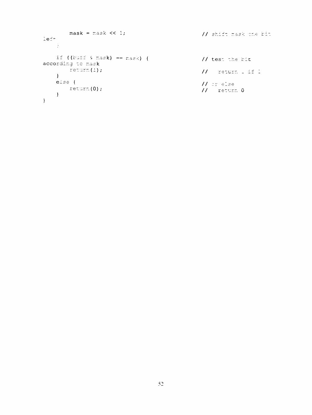
mask = r.ask << 1; // shift ^er-
((bu: :ask) == r asK) {
accoram; :c mask return(l);
} else {
return(0); }
// teso ohe cit
// return . i:
// or else
// return 0

PERMISSION TO COPY
In presenting this thesis in partial fulfiUment of the requirements for a
master's degree at Texas Tech University or Texas Tech University Health Sciences
Center, I agree that the Library and my major department shall make it freely
available for research purposes. Permission to copy this thesis for scholarly
purposes may be granted by the Director of the Library or my major professor.
It is understood that any copying or publication of this thesis for financial gain
shall not be allowed without my further written permission and that any user
may be liable for copyright infringement.
Agree (Permission is grgjited.)
Stifdent'^ignature Date
Disagree (Permission is not granted.)
Student's Signature Date