Embed Size (px)
Citation preview
http://www.iaeme.com/IJCIET/index.asp 234 [email protected]
International Journal of Civil Engineering and Technology (IJCIET) Volume 9, Issue 4, April 2018, pp. 234–247, Article ID: IJCIET_09_04_026
Available online at http://www.iaeme.com/ijciet/issues.asp?JType=IJCIET&VType=9&IType=4
ISSN Print: 0976-6308 and ISSN Online: 0976-6316
© IAEME Publication Scopus Indexed
COMPARATIVE STUDY OF GEOPOLYMER
CONCRETE WITH STEEL FIBERS IN BEAM
COLUMN JOINT
Megharima Datta
M. Tech, structural engineering,
SRM University, Kattanukulathur, Tamilnadu, India
G. Premkumar
Asst. Prof. Department of Civil engineering,
SRM University, Kattanukulathur, Tamilnadu, India
ABSTRACT
An equivalent test examination was done on the quality and strength of conventional
concrete and geo polymer concrete with and without steel fibers in beam column joints
and the outcomes were analyzed. Geo polymer concrete are selected building materials
which can be utilized as a part inplace of Ordinary Portland cement(OPC) and can
undoubtedly change the improvement of development industry without causing damage
to the nature. In geo polymer concrete we will utilize fly slag, GGBS, Alkaline activated
solution as an arrangement. The use of cement emits carbon dioxide which causes
pollution. This work has been done to research the Geo polymer concrete (GPCs) with
the utilization of steel fiber and compare it with conventional concrete with steel fibers.
By making Four GPC blends 1) fly ash remains 60% and 40% GGBS, 2) fly slag 50%
and GGBS 50%, 3) 40% fly ash and 60% GGBS, 4) 30% fly ash and 70% GGBS
alongside control GPC blend which is then included with snared steel fibers. In
conventional concrete we will assess utilizing with and without steel fi. The volume
portion of steel strands utilized was 0.75%, 1.5%, 2.5%. Four Geo polymer solid beam
column joints and conventional solid beam column joint were made and tried under half
cyclic loading to explore the execution of the shaft segment joints. The hysteriasis curve,
load deflection curve, history of cyclic load sequence, energy dissipation capacity,
stiffness degradation, ductility, crack pattern were assessed from the test outcomes. The
correlation of test outcomes uncovered that the quality and conduct of plain and fiber
fortified geo polymer solid beam column joints are possibly superior when compared
with conventional solid joints.
Key word: Geopolymer Concrete, Beam Column Joint, Ductility, Energy Dissipation
Capacity, Hysteriasis Curves, Stiffness.
Comparative Study of Geopolymer Concrete with Steel Fibers In Beam Column Joint
http://www.iaeme.com/IJCIET/index.asp 235 [email protected]
Cite this Article: Megharima Datta and G. Premkumar, Comparative Study of
Geopolymer Concrete with Steel Fibers in Beam Column Joint, International Journal of
Civil Engineering and Technology, 9(4), 2018, pp. 234–247.
http://www.iaeme.com/ijciet/issues.asp?JType=IJCIET&VType=9&IType=4
1. INTRODUCTION
We require regular material to make advancement with less cost and supportable change. The
essential component of regular concrete is Ordinary Portland cement (OPC). The standard
Portland concrete is involved with limestone and it is diminishing well ordered and as we are
using, it is harming the earth by emanating carbon dioxide (Bakri et. al. 2011). Geopolymers
are binders utilized as an option for cement. Davidovits recommended that fasteners are made
by a polymeric reaction of alkaline liquids with silica and aluminium in source symptom
materials, for instance, fly ash remains, GGBS, rice husk powder. He named these elective
binders as geopolymers. Concrete made by using geopolymers as binders are called geopolymer
concrete (GPC). The pulverised fuel cinder are of two sorts viz.class C and class F and these
fly ash remains based geopolymer concrete has pozzolanic properties like OPC based general
bond. Low-calcium fly ash debris stays based geopolymer concrete has astonishing
compressive quality and it perseveres no drying shrinkage and low creep, it has brilliant
insurance from sulfate attacks, and besides extraordinary destructive security. Since it uses
waste material like fly ash as the central settling, it can be seen as a reasonable green material
(Hardjito et. al.2004). Not withstanding whether the bar and section in a braced strong edge
remains strong still the whole structure will get impacted once the joint falls flat. As a result of
critical zone, the joint annihilation are suspected to demolition more faster than some other
building part. The interior joint doesn't get so much impacted yet the exterior one gets more
affected. So the ductility and energy dissipating capacity of the structures are basic parametres.
It is fundamental to affirm the shear protection and anchorage condition of the help
encountering the joints. A couple of Studies are investigated on the mechanical properties of
GPC and it showed that it has better mechanical properties and durability characteristics than
ordinary concrete (Ganesan et. al. 2015). Finds out about the examination of the fundamental
direct of GPC beams indicated better strength, enhanced load passing on confine and flexural
quality than conventional concrete beams (Dattatreya et. al. 2011). In the midst of shake in
different parts of the world, the arrangement of reinforced strong structures with high
adaptability and flexibility are more indispensable. Due to honest to goodness indicating of
fortification in joint the structures secure quality and adaptability. The joints get hurt in light of
the obliged subjected to it more than the arrangement controls in cyclic way. Under seismic
power, the section joint is subjected to even and vertical shear controls whose degrees are
generally higher than those inside the touching shafts and portions. Straightforwardly utilizing
fibers isn't new. By the 1960s, steel, glass (GFRC), and manufactured fibers for example
polypropylene, basalt fibers were utilized as a pieces in concrete, and research into new FRCs
proceeds with today. A couple of sorts of fibers convey more noticeable impact, abrasion, and
crush assurance in concrete. Two or three examinations investigated the relationship between
the split tensile and compressive nature of glass fiber strengthened concrete (GFRC) and
polypropylene fiber maintained concrete (PFRC). The examinations looked in with the general
mish-mash of trapped end steel filaments, metal secured (brass coated) steel strands and
polypropylene fibers in the outsiden joint under cyclic loading. Fiber invigorated strong restrict
more cycles loading even after crack. Development of steel fibers would improve stiffness,
energy dissipation capacity, harm resilience and damage protection of strong, which are most
fundamental properties for structures under seismic loading (Haach et. al. 2008). The test
examinations on the assistant direct of conventional joints exhibited that the nature of a joint
depends upon components, for instance, listing of help, security quality, scattering of
Megharima Datta and G. Premkumar
http://www.iaeme.com/IJCIET/index.asp 236 [email protected]
interfacing ties, geometry of bar and fragment, nature of strong, % of fibers (Ganesan et. al.
2014). In spite of the way that immense number of studies have been directed to fathom the
mechanical properties of GPC, attempts on the examination of geopolymer strong joints have
been keep running over anyway it showed variety comes to fruition.
2. EXPERIMENTAL PROGRAMME
The test comprises of making and testing of plain and fiber fortified geopolymer concrete in
exterior section joints (GBJ) and conventional concrete solid joints (CCJ) under half cyclic
loading. The diverse measurement of steel fibers utilized are the one with most noteworthy
compressive quality i.e 2.5%.
3. SCOPE OF THE STUDY
The present work aims at the comparative study of the beam column joint made by conventional
concrete and geopolymer concrete with and without steel fib ers under half cyclic loading. In
this study we compared the mechanical properties such as compressive strength, split tensile
and young’s modulus and also we compared load deflection curve, hysteriasis curve, ductility,
stiffness, energy dissipation and crack pattern.
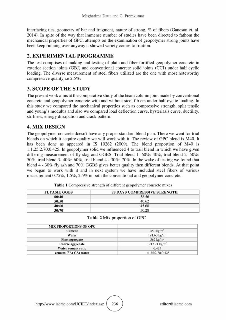
4. MIX DESIGN
The geopolymer concrete doesn't have any proper standard blend plan. There we went for trial
blends on which it acquire quality we will work with it. The review of GPC blend is M40. It
has been done as appeared in IS 10262 (2009). The blend proportion of M40 is
1:1.25:2.70:0.425. In geopolymer solid we influenced 4 to trail blend in which we have given
differing measurement of fly slag and GGBS. Trial blend 1- 60%: 40%, trial blend 2- 50%:
50%, trial blend 3- 40%: 60%, trial blend 4 - 30%: 70%. In the wake of testing we found that
blend 4 - 30% fly ash and 70% GGBS gives better quality then different blends. At that point
we began to work with it and in next system we have included steel fibers of various
measurement 0.75%, 1.5%, 2.5% in both the conventional and geopolymer concrete.
Table 1 Compressive strength of different geopolymer concrete mixes
FLYASH: GGBS 28 DAYS COMPRESSIVE STRENGTH
60:40 38.56
50:50 40.62
40:60 45.68
30:70 50.28
Table 2 Mix proportion of OPC
MIX PROPORTIONS OF OPC
Cement 450 kg/m3
Water 191.60 kg/m3
Fine aggregate 562 kg/m3
Coarse aggregate 1217.21 kg/m3
Water cement ratio 0.425
cement: FA: CA: water 1:1.25:2.70:0.425
Comparative Study of Geopolymer Concrete with Steel Fibers In Beam Column Joint
http://www.iaeme.com/IJCIET/index.asp 237 [email protected]
Table 3 Mix proportion of GPC
MIX PROPORTION FOR GPC
Fly ash+ GGBS 280+90.84 kg/m3
Reaction generating liquid 0.45
Fine aggregate 562 kg/m3
Coarse aggregate 1217.17kg/m3
(fly ash+ GGBS): FA:CA: AAS (0.3+0.7):1.25:2.70:0.45
5. MATERIALS USED
GPC were made up of low calcium fly ash (Class F), GGBS, coarse aggregate, fine aggregate,
alkaline solution (RGL). Crushed granite stones having nominal size 20 mm and natural river
sand were used as coarse aggregate and fine aggregate respectively. Both the coarse and fine
aggregate used were conforming to Zone II of IS 383(1970). The material properties of coarse
and fine aggregates are shown along with the geopolymer concrete we have used AAS (RGL1).
Ordinary Portland cement of 53 grade conforming to IS: 12269 (1987) was used for preparing
conventional concrete. Hooked end steel fibers with aspect ratio 58.33 (length 30 mm and
diameter 0.6 mm) were used to prepare the steel fiber reinforced concrete mix.
Table parameters of specimen
PARAMETRES COARSE AGGREGATE FINE AGGREGATE
Nominal maximum size 20mm 4.75mm
Specific gravity 2.85 2.36
Fineness modulus 3.07 4.23
5.1. FLY ASH
The waste material that we procured from the ignition of pummeled coal which is gathered by
mechanical means from the gases of thermal power plants. In this trial work, the fly ash remains
which we have utilized low calcium based fly ash. This fly ash helps in workability, opposing
substance and decrease thermal split. The compound arrangement of fly fiery debris is SiO2 =
49.45, Al2O3 = 29.61, Fe2O3 = 10.72, CaO= 3.47, MgO= 1.3, Na2O= 0.31, K2O = 0.54,TiO2 =
1.76, Mn2O3 = 0.17, SO3 = 0.27, P2O5 = 0.53. The particular gravity of fly powder is 2.1 and
the fineness modulus is 8%.
5.2. GGBS (Ground Granulated Blast Furnace Slag)
The chemical composition of GGBS is SiO2 33.45, Al2O3 13.46 Fe2O3 0.31, CaO 41.7, MgO
5.99, Na2O 0.16, K2O 0.29, TiO2 0.84, Mn2O3 0.40, SO3 2.74. The specific gravity of GGBS is
2.8 and the fineness modulus is 14%.
5.3. CEMENT
In this experiment we have used OPC 53. The specific gravity of cement is 3.12 and the fineness
is 9%.
5.4. STEEL FIBERS
In this analysis we have utilized snared end steel filaments having RC 35/60 BN. The aspect
ratio proportion is 58.33. The specific gravity is 7.8 g/cc. We have utilized this snared end steel
strands in both the solid i.e concrete and geo polymer concrete. This fibers is utilized in light
of the fact that it has the property of opposing against crack and crack proliferation. By utilizing
steel fibers the ductility is expanded with expanding dose of steel fibers.
Megharima Datta and G. Premkumar
http://www.iaeme.com/IJCIET/index.asp 238 [email protected]
5.5. ALKALINE ACTIVATED SOLUTION
It is also known as AAS. AAS content is made by 1:1. For making AAS we need 50% lye
(caustic soda) = 1, Na2Si03 (sodium silicate) have molar ratio = 2, which comprises of SiO2 =
30%, Na2O = 15%, H2O = 55%. The final molar ratio Na2SiO3/NaOH = 0.56 as the alkaline
liquid to activate the source material and those are commercially available.
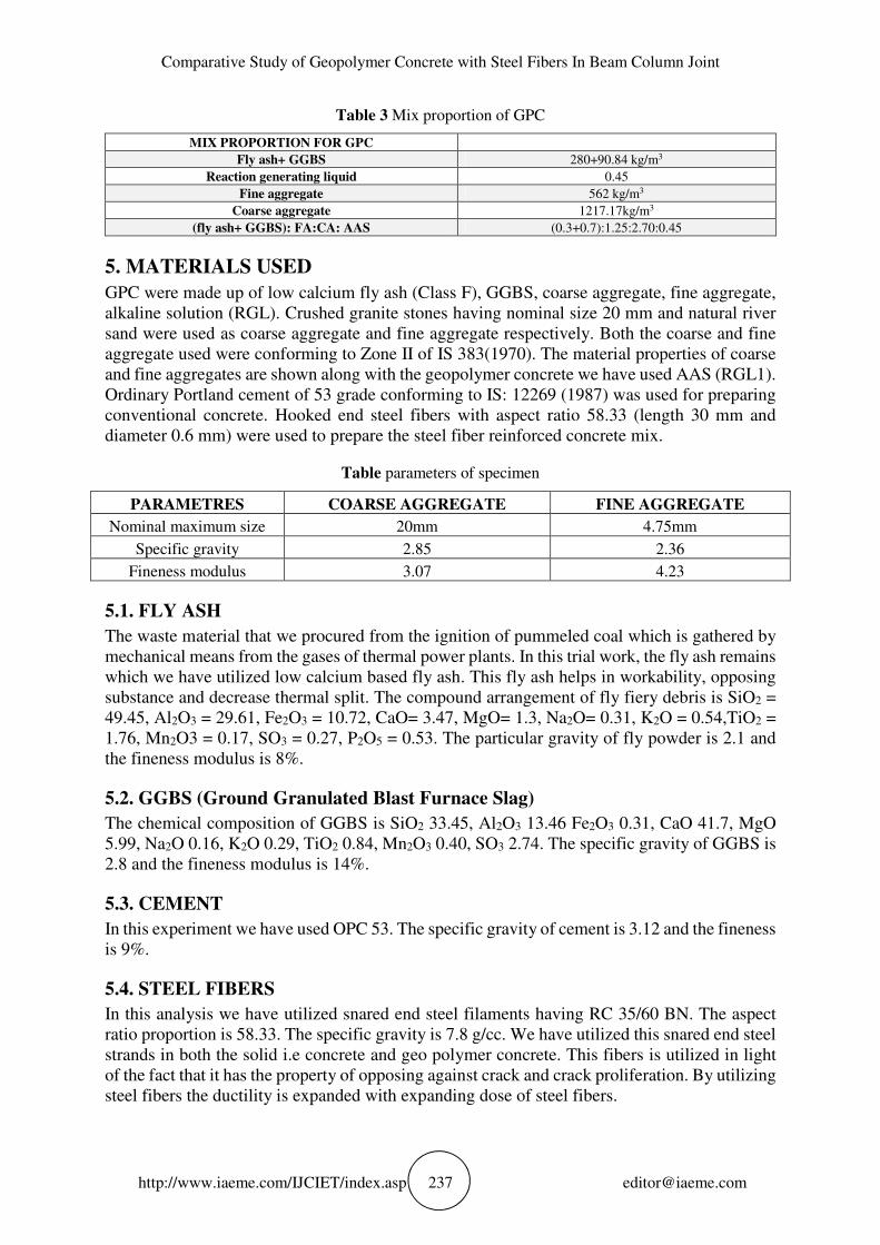
6. TESTING OF MECHANICAL PROPERTIES
Before making, the wooden moulds are painted with oil or oil type material (grease). The
materials are blended in the tilting mixingmachine. The Geopolymer concrete are set up by
blending fly ash, GGBS, fine aggregate, coarse aggregate and alkaline activated solution. Also,
similarly conventional concrete is made by blending cement, fine aggregate, coarse aggregate
and water. For compressive quality the solid cubes were thrown of 150mm x 150mm and for
split tensile and young’s modulus we cast cylinder of 300 mm x 150 mm and we will demould
it after 24 hrs. We will cure it for 7 days and 28 days. Aside from the plain traditional and
geopolymer solid we will include steel fibers of various measurements in both the conventional
and geopolymer concrete.
Table 5 Mechanical properties of specimens
MIX Compressive strength
(N/mm2 )
Split tensile
Strength (N/mm2 )
Youngs modulus
(N/mm2 )
OPC 49.11 2.80 26157
OPC 0.75%SF 52.33 3.58 -
OPC 1.5%SF 54.94 4.1 -
OPC 2.5% SF 58.66 4.56 31248
GPC 50.28 3.3 38246
GPC 0.75% SF 53 3.88 -
GPC 1.5% SF 55.48 4.04 -
GPC 2.5% SF 59.10 4.81 41135
Figure 1 compressive strength, split tesile, young’s modulus
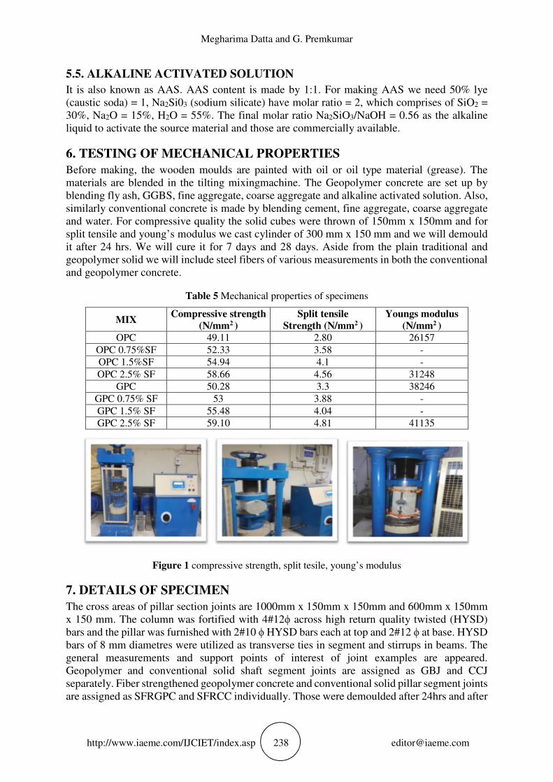
7. DETAILS OF SPECIMEN The cross areas of pillar section joints are 1000mm x 150mm x 150mm and 600mm x 150mm
x 150 mm. The column was fortified with 4#12ϕ across high return quality twisted (HYSD)
bars and the pillar was furnished with 2#10 ϕ HYSD bars each at top and 2#12 ϕ at base. HYSD
bars of 8 mm diametres were utilized as transverse ties in segment and stirrups in beams. The
general measurements and support points of interest of joint examples are appeared.
Geopolymer and conventional solid shaft segment joints are assigned as GBJ and CCJ
separately. Fiber strengthened geopolymer concrete and conventional solid pillar segment joints
are assigned as SFRGPC and SFRCC individually. Those were demoulded after 24hrs and after
Comparative Study of Geopolymer Concrete with Steel Fibers In Beam Column Joint
http://www.iaeme.com/IJCIET/index.asp 239 [email protected]
that cured under the water for 28 days and the geopolymer concrete BCJ example have been
cured in ordinary temperature.
Figure 2 Reinforcement details
Figure 3 Reinforcement with wooden mould and demoulding after 24 hrs.
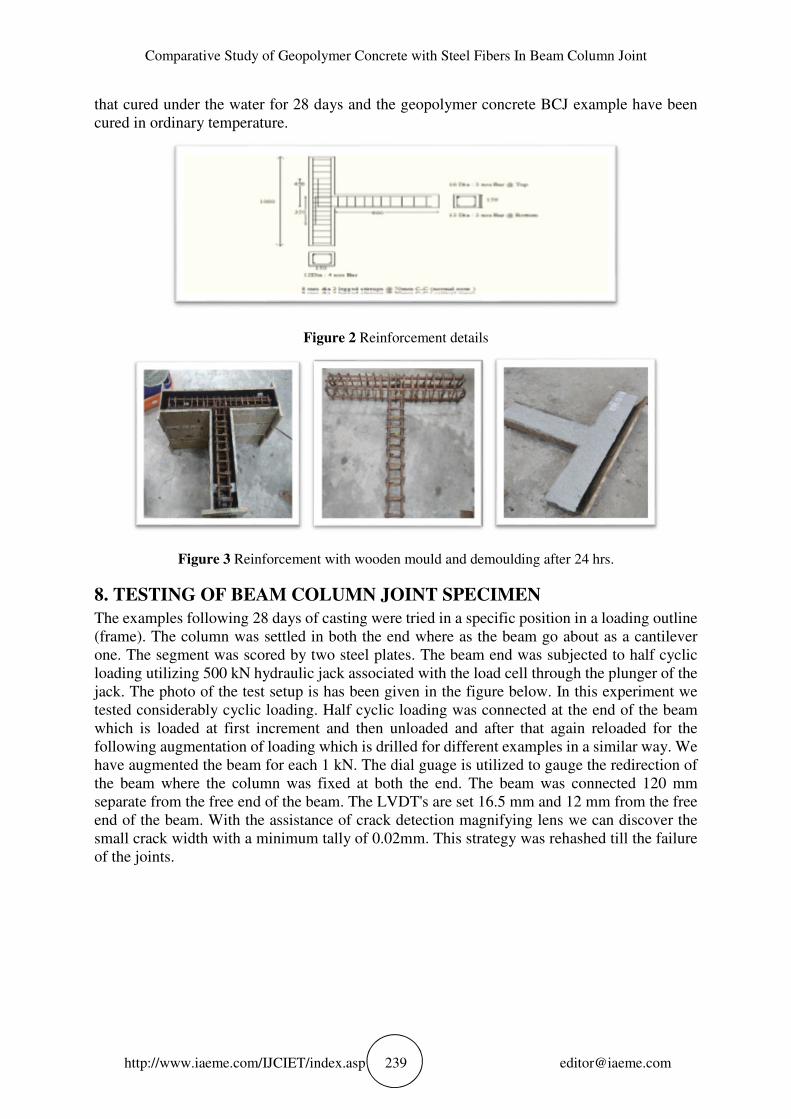
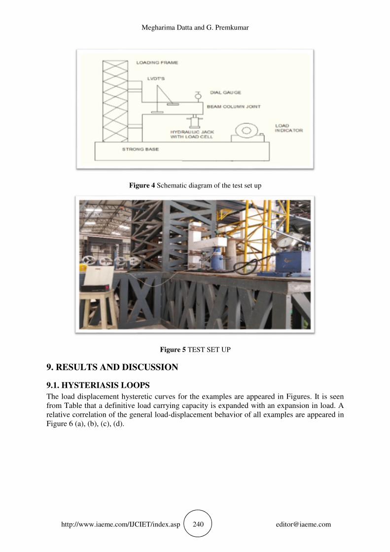
8. TESTING OF BEAM COLUMN JOINT SPECIMEN
The examples following 28 days of casting were tried in a specific position in a loading outline
(frame). The column was settled in both the end where as the beam go about as a cantilever
one. The segment was scored by two steel plates. The beam end was subjected to half cyclic
loading utilizing 500 kN hydraulic jack associated with the load cell through the plunger of the
jack. The photo of the test setup is has been given in the figure below. In this experiment we
tested considerably cyclic loading. Half cyclic loading was connected at the end of the beam
which is loaded at first increment and then unloaded and after that again reloaded for the
following augmentation of loading which is drilled for different examples in a similar way. We
have augmented the beam for each 1 kN. The dial guage is utilized to gauge the redirection of
the beam where the column was fixed at both the end. The beam was connected 120 mm
separate from the free end of the beam. The LVDT's are set 16.5 mm and 12 mm from the free
end of the beam. With the assistance of crack detection magnifying lens we can discover the
small crack width with a minimum tally of 0.02mm. This strategy was rehashed till the failure
of the joints.
Megharima Datta and G. Premkumar
http://www.iaeme.com/IJCIET/index.asp 240 [email protected]
Figure 4 Schematic diagram of the test set up
Figure 5 TEST SET UP
9. RESULTS AND DISCUSSION
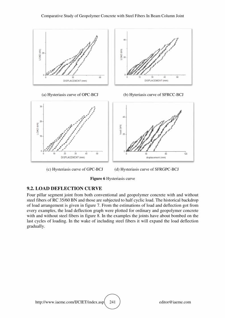
9.1. HYSTERIASIS LOOPS
The load displacement hysteretic curves for the examples are appeared in Figures. It is seen
from Table that a definitive load carrying capacity is expanded with an expansion in load. A
relative correlation of the general load-displacement behavior of all examples are appeared in
Figure 6 (a), (b), (c), (d).
Comparative Study of Geopolymer Concrete with Steel Fibers In Beam Column Joint
http://www.iaeme.com/IJCIET/index.asp 241 [email protected]
(a) Hysteriasis curve of OPC-BCJ (b) Hyteriasis curve of SFRCC-BCJ
(c) Hysteriasis curve of GPC-BCJ (d) Hysteriasis curve of SFRGPC-BCJ
Figure 6 Hysteriasis curve
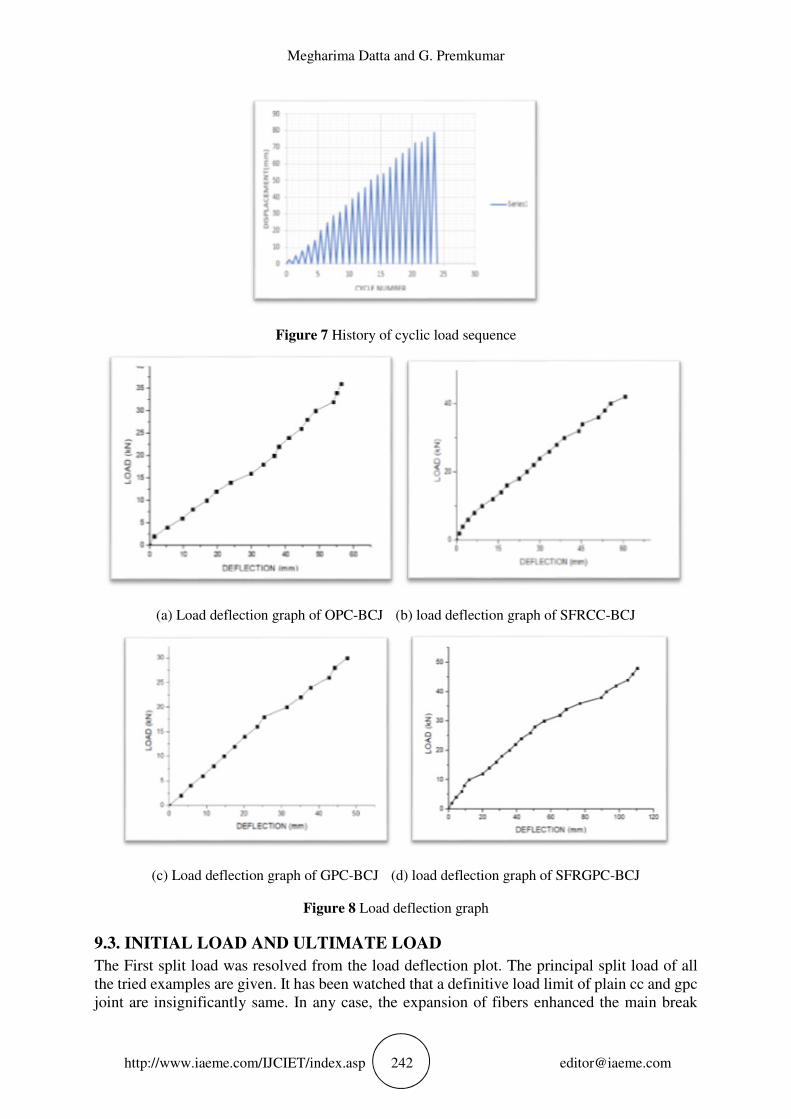
9.2. LOAD DEFLECTION CURVE
Four pillar segment joint from both conventional and geopolymer concrete with and without
steel fibers of RC 35/60 BN and those are subjected to half cyclic load. The historical backdrop
of load arrangement is given in figure 7. From the estimations of load and deflection got from
every examples, the load deflection graph were plotted for ordinary and geopolymer concrete
with and without steel fibers in figure 8. In the examples the joints have about bombed on the
last cycles of loading. In the wake of including steel fibers it will expand the load deflection
gradually.
Megharima Datta and G. Premkumar
http://www.iaeme.com/IJCIET/index.asp 242 [email protected]
Figure 7 History of cyclic load sequence
(a) Load deflection graph of OPC-BCJ (b) load deflection graph of SFRCC-BCJ
(c) Load deflection graph of GPC-BCJ (d) load deflection graph of SFRGPC-BCJ
Figure 8 Load deflection graph
9.3. INITIAL LOAD AND ULTIMATE LOAD
The First split load was resolved from the load deflection plot. The principal split load of all
the tried examples are given. It has been watched that a definitive load limit of plain cc and gpc
joint are insignificantly same. In any case, the expansion of fibers enhanced the main break
Comparative Study of Geopolymer Concrete with Steel Fibers In Beam Column Joint
http://www.iaeme.com/IJCIET/index.asp 243 [email protected]
load, which might be because of the increment in ductile strain conveying limit of concrete in
the area of fibers. The estimations of extreme load of tried examples are given. Expansion of
steel fibers in the concrete expanded a definitive load carrying limit of the joints, because of the
crossing over of miniaturized scale breaks by steel fibers.
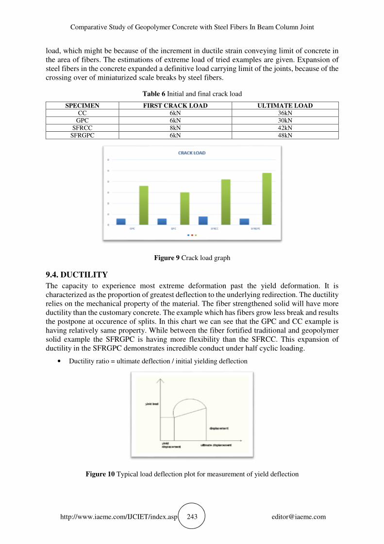
Table 6 Initial and final crack load
SPECIMEN FIRST CRACK LOAD ULTIMATE LOAD
CC 6kN 36kN
GPC 6kN 30kN
SFRCC 8kN 42kN
SFRGPC 6kN 48kN
Figure 9 Crack load graph
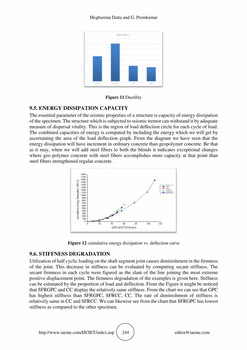
9.4. DUCTILITY
The capacity to experience most extreme deformation past the yield deformation. It is
characterized as the proportion of greatest deflection to the underlying redirection. The ductility
relies on the mechanical property of the material. The fiber strengthened solid will have more
ductility than the customary concrete. The example which has fibers grow less break and results
the postpone at occurence of splits. In this chart we can see that the GPC and CC example is
having relatively same property. While between the fiber fortified traditional and geopolymer
solid example the SFRGPC is having more flexibility than the SFRCC. This expansion of
ductility in the SFRGPC demonstrates incredible conduct under half cyclic loading.
• Ductility ratio = ultimate deflection / initial yielding deflection
Figure 10 Typical load deflection plot for measurement of yield deflection
Megharima Datta and G. Premkumar
http://www.iaeme.com/IJCIET/index.asp 244 [email protected]
Figure 11 Ductility
9.5. ENERGY DISSIPATION CAPACITY
The essential parameter of the seismic properties of a structure is capacity of energy dissipation
of the specimen. The structure which is subjected to seismic tremor can withstand it by adequate
measure of dispersal vitality. This is the region of load deflection circle for each cycle of load.
The combined capacities of energy is computed by including the energy which we will get by
ascertaining the area of the load deflection graph. From the diagram we have seen that the
energy dissipation will have increment in ordinary concrete than geopolymer concrete. Be that
as it may, when we will add steel fibers to both the blends it indicates exceptional changes
where geo polymer concrete with steel fibers accomplishes more capacity at that point than
steel fibers strengthened regular concrete.
Figure 12 cumulative energy dissipation vs. deflection curve
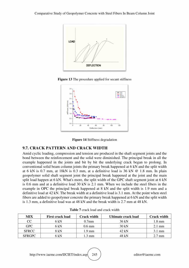
9.6. STIFFNESS DEGRADATION
Utilization of half cyclic loading on the shaft segment joint causes diminishment in the firmness
of the joint. This decrease in stiffness can be evaluated by computing secant stiffness. The
secant firmness in each cycle were figured as the slant of the line joining the most extreme
positive displacement point. The firmness degradation of the examples is given here. Stiffness
can be estimated by the proportion of load and deflection. From the Figure it might be noticed
that SFRGPC and CC display the relatively same stiffness. From the chart we can see that GPC
has highest stiffness than SFRGPC, SFRCC, CC. The rate of diminishment of stiffness is
relatively same in CC and SFRCC. We can likewise see from the chart that SFRGPC has lowest
stiffness as compared to the other specimen.
Comparative Study of Geopolymer Concrete with Steel Fibers In Beam Column Joint
http://www.iaeme.com/IJCIET/index.asp 245 [email protected]
Figure 13 The procedure applied for secant stiffness
Figure 14 Stiffness degradation
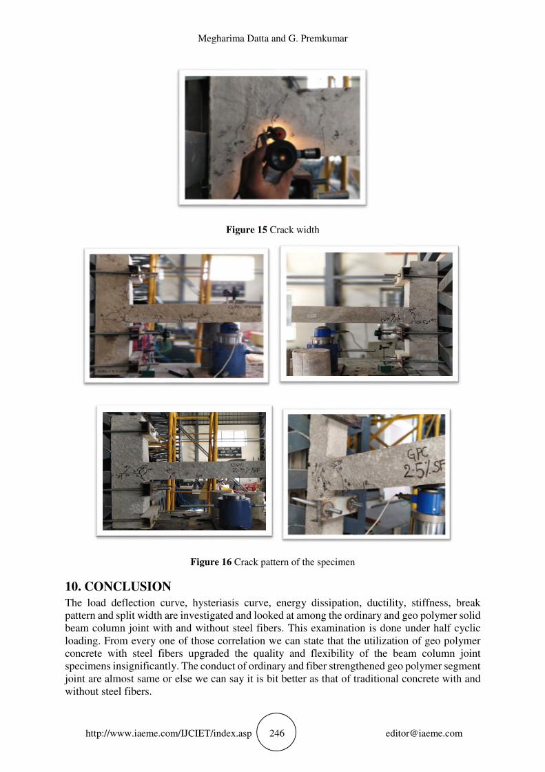
9.7. CRACK PATTERN AND CRACK WIDTH
Amid cyclic loading, compression and tension are produced in the shaft segment joints and the
bond between the reinforcement and the solid were diminished. The principal break in all the
example happened in the joints and bit by bit the underlying crack began to prolong. In
conventional solid beam column joints the primary break happened at 6 kN and the split width
at 6 kN is 0.7 mm, at 18kN is 0.3 mm, at a definitive load is 36 kN @ 1.8 mm. In plain
geopolymer solid shaft segment joint the principal break happened at the joint and the main
split load happen at 6 kN. What's more, the split width of the GPC shaft segment joint at 6 kN
is 0.6 mm and at a definitive load 30 kN is 2.1 mm. When we include the steel fibers in the
example in OPC the principal break happened at 8 kN and the split width is 1.9 mm and a
definitive load at 42 kN. The break width at a definitive load is 3.1 mm. At the point when steel
fibers are added to geopolymer concrete the primary break happened at 6 kN and the split width
is 1.3 mm, a definitive load was at 48 kN and the break width is 2.7 mm at 48 kN.
Table 7 crack load and crack width
MIX First crack load Crack width Ultimate crack load Crack width
CC 6 kN 0.7mm 36 kN 1.8 mm
GPC 6 kN 0.6 mm 30 kN 2.1 mm
SFRCC 8 kN 1.9 mm 42 kN 3.1 mm
SFRGPC 6 kN 1.3 mm 48 kN 2.7 mm
Megharima Datta and G. Premkumar
http://www.iaeme.com/IJCIET/index.asp 246 [email protected]
Figure 15 Crack width
Figure 16 Crack pattern of the specimen
10. CONCLUSION
The load deflection curve, hysteriasis curve, energy dissipation, ductility, stiffness, break
pattern and split width are investigated and looked at among the ordinary and geo polymer solid
beam column joint with and without steel fibers. This examination is done under half cyclic
loading. From every one of those correlation we can state that the utilization of geo polymer
concrete with steel fibers upgraded the quality and flexibility of the beam column joint
specimens insignificantly. The conduct of ordinary and fiber strengthened geo polymer segment
joint are almost same or else we can say it is bit better as that of traditional concrete with and
without steel fibers.
Comparative Study of Geopolymer Concrete with Steel Fibers In Beam Column Joint
http://www.iaeme.com/IJCIET/index.asp 247 [email protected]
• First split load of OPC, GPC and SFRGPC are equivalent and a definitive load limit of OPC
and GPC are relatively equivalent though the SFRGPC is having most noteworthy extreme load
conveying limit.
• In ductility the specimen OPC is more bendable than GPC. Be that as it may, when we added
steel fibers to the SFRGPC achieves more ductility than SFRCC.
• Energy dissipation capacity of CC and SFRCC is imperceptibly same and the GPC example are
relatively same as that of CC and SFRCC yet SFRGPC bar section joint has accomplished most
noteworthy dissipation capacity.
• In the rate of diminishment of stiffness nearly CC, SFRCC, GPC example demonstrates the
same and the SFRGPC demonstrates that it has the ability to oppose in cyclic loading. The GPC
specimen has more stiffness compared to CC, SFRCC, SFRGPC.
• Based on a definitive load conveying limit SFRGPC has 1.14 times less split width than SFRCC.
REFERENCE
[1] Al Bakri, M.M.Mohammed, H.Kamarudin, H.Niza, I.K.Zarina (2011), “review on flyash
based geopolymer concrete without portland cement”, J.Eng. Tech. Res., Vol. 3 No. 1, 1-4.
[2] Hardjito, D.Wallah, S.E.Sumajouw, D.M.Rangan, (2004), “On the development of flyash
based geopolymer concrete”, ACI Mater.J.Am. Concrete Inst., Vol. 101 No. 6, 467-472.
[3] Ganesan N., Abraham R., Raj S.D. (2015) “ Durability characteristics of steel fibers
reinforced geopolymer concrete”, Construction building material, (93), 471-476.
[4] Dattatreya J.K., Rajamane N.P., Sabitha D., Ambily P.S., Nataraj M.C. (2011), “Flexural
behavior of reinforced geopolymer concrete beam”, J. Civil Structural engineering , Vol. 2
No. 1, 138.
[5] Haach V.G., El Debs, M.K. (2008), “Evaluation of the influence of the column axial load
on the behavior of monotonically loaded Reinforced concrete exterior beam-column joints
through numerical simulations”, Engineering Structural, Vol. 30, No. 4, 965-975.
[6] Ganesan N., Indira P.V. and Sabeena M.V. (2014), “Behaviour of hybrid fibre reinforced
concrete beam-column joints under reverse cyclic loads”, Material Des., (54), 686-693.
[7] S. Deepa Raj, N. Ganesan, Ruby Abraham and Anumol Raju (2016), “Behavior of
geopolymer concrete and conventional concrete beam column joint under reverse cyclic
loading”, Advances in Concrete Construction, Vol. 4, No. 3, 161-172.
[8] K.R. Bindhu, P.M. Sukumar and K.P. Jaya (2009), “Performance of exterior beam column
joints under seismic type loading”, ISET Journal of Earthquake Technology, Paper No. 503,
Vol. 46, No. 2, pp. 47–64.
[9] M. Keerthi and K. Prasanthi, Experimental Study On Coir Fibre Reinforced Fly Ash Based
Geopolymer Concrete For 10m. International Journal of Civil Engineering and Technology,
8(1), 2017, pp. 464–472
[10] P A N V L NarasimhaSwamy, U.VenuGopal and K Prasanthi, Experimental Study on Coir
Fibre Reinforced Flyash Based Geopolymer Concrete With 12m & 10m Molar Activator
[11] IS: 10262 (2009), “Recommended guidelines for concrete mix design”, Code of Practice,
BIS, New Delhi.