Embed Size (px)
Citation preview
MATEC Web of Conferences 9, 03003 (2013)DOI: 10.1051/matecconf/20130903003C© Owned by the authors, published by EDP Sciences, 2013
Comparative assessment of CFD Tools and the EurocodeMethodology in describing Externally Venting Flames
Eleni K. Asimakopouloua, Dionysios I. Kolaitis and Maria A. Founti
Laboratory of Heterogeneous Mixtures and Combustion Systems, Thermal EngineeringSection, School of Mechanical Engineering, National Technical University of Athens 9 HeroonPolytechneiou St., Polytechneioupoli Zografou, Athens 15780, Greece
Abstract. The ability of currently available Computational Fluid Dynamics (CFD) tools to adequatelydescribe Externally Venting Flames (EVF) is assessed, aiming to demonstrate compliance withperformance-based fire safety regulations. The Fire Dynamics Simulator (FDS) CFD tool is used tosimulate the EVF characteristics in a corridor-compartment-façade configuration exposed to natural fireconditions. Numerical results of the temporal evolution of gas velocity, gas temperatures and flame shapeare obtained for both the interior and the exterior of the compartment. Predictions are compared to respectiveexperimental data, as well as to correlations suggested by the Eurocode methodology. The effects ofventilation conditions are investigated by simulating both Forced Draught (FD) and No Forced Draught(NoFD) test cases. The obtained results suggest that currently available CFD tools are capable of achievinggood qualitative agreement with experimental data and, in certain cases (e.g. FD conditions), adequatequantitative agreement, that generally outperforms the Eurocode prescriptive methodology.
1. INTRODUCTION
In a fully developed, under-ventilated compartment fire, flames may spill out of external openings (e.g.windows), should the glazing fail. Externally Venting Flames (EVF) may pose a significant risk of firespreading to adjacent floors or buildings, especially nowadays when there is an ever-increasing trend ofusing combustible materials in building façades for energy performance purposes. However, most firesafety codes are lacking specific methodologies to evaluate the risks associated with EVF. In this context,the Eurocode design guidelines [1], recently implemented in the European Union (E.U.), contain a setof comprehensive correlations, focusing on the protection of steel and timber elements from EVF.
Historically, fire protection systems in buildings have been commonly regulated using “prescriptive”codes and methodologies. Today, there is a growing worldwide trend towards implementing modern“performance-based” codes, which offer a range of advantages. The implementation of performance-based codes requires the use of advanced simulation tools, such as Computational Fluid Dynamics(CFD) codes. CFD tools can provide a wealth of information regarding the detailed characteristics ofthe flow- and thermal-field developing inside or outside the compartment; as a result, the thermal impactof EVF on the façade elements can be thoroughly assessed. Despite this fact, there are few numericalsimulation studies available that focus on EVF and relevant façade fire safety issues [2–5]. Until now,emphasis was given mainly on the study of fire behaviour inside compartments and the effect of thevarious ventilation parameters on the fire environment, e.g. [6, 7], and not on the effects of fire spreadingand smoke propagation beyond the compartment of origin. The main scope of the present study is to
ae-mail: [email protected]
This is an Open Access article distributed under the terms of the Creative Commons Attribution License 2.0, which permitsunrestricted use, distribution, and reproduction in any medium, provided the original work is properly cited.
Article available at http://www.matec-conferences.org or http://dx.doi.org/10.1051/matecconf/20130903003
MATEC Web of Conferences
assess the ability of currently available CFD tools to adequately describe the EVF characteristics, withthe aim of demonstrating compliance with performance-based fire safety regulations. In this context,a CFD tool is used to simulate a real scale compartment-façade configuration exposed to natural fireconditions. The obtained predictions are compared to available experimental data, as well as to valuesusing the relevant correlations proposed in the Eurocodes. EFV characteristics are mainly determined byopening geometry, ventilation conditions, fuel load and building material properties [8]. In this context,the effect of ventilation conditions is investigated by performing a parametric study for both ForcedDraught (FD) and No Forced Draught (NoFD) conditions.
2. EUROPEAN FIRE SAFETY LEGISLATION
Building codes and regulations include methods and measures in order to ensure maximum safetyagainst fire events. In the E.U., the structural Eurocodes in combination with each member state’sregulations are applied in order to determine a wide range of analytical procedures and design rulesconcerning the construction of structures; in this context, a set of minimum requirements for the designand construction of buildings is proposed.
2.1 The Eurocode methodology
The structural Eurocodes form a set of documents that determine the imposed actions in order toassist the structural design of buildings. The design procedure for a building includes methods fordescribing the behaviour of the structure at elevated temperatures, its potential heat exposure and theeffects of active or/and passive fire protection systems. Actions for designing load bearing structuresare prescribed in EN 1991, Eurocode 1 (EC1) [1]. More specifically, Part 1-2 of EN 1991 gives generalprinciples and application rules regarding the thermal and mechanical actions on structures exposed tofire. There are two ways of demonstrating compliance with EC1, either following the prescriptive or theperformance-based approach. The prescriptive approach uses nominal fires to generate thermal actionsand indicates a set of simple rules for the design and verification of structural elements. This methodis valid for fire loads higher than 200 MJ/m2, near rectangular enclosures, floor areas less than 500 m2,heights less than 4 m, no ceiling openings and time dependent thermal properties for façade elements.The performance-based approach (as prescribed in Annex D of the EC1), using fire safety engineeringtechniques, such as zone or CFD models, refers to thermal actions based on physical and chemicalparameters. However, no particular guidance is given by the EC1 on the actual set up of such a case,thus leaving the identification of the means to demonstrate compliance to the engineer.
2.2 Eurocode prescriptive methodology
The prescriptive method described in Annex B of the EC1 “Thermal actions of external members”,allows the calculation of the maximum temperatures inside the fire compartment, the geometry andtemperature profile of the EVF and the relevant convection and radiation parameters. The effects ofwind, ventilation conditions and existence of balconies in the EVF’s characteristics are also taken intoaccount. If there are windows on opposite sides of the compartment or air flow from another source,then Forced Draught (FD) conditions apply. Otherwise, No Forced Draught (NoFD) conditions are usedfor the calculations. The EVF temperature along the centerline axis is given by Eq. (1) and (2), for theFD and NoFD ventilation conditions, respectively.
Tz = (Tw − To)
(1 − 0.3325
(Lx
√Av
Q
))+ To with Lf
√Av
Q< 1 (1)
03003-p.2
1st International Seminar for Fire Safety of Facades, Paris (France), 2013
Tz = (Tw − To)
(1 − 0.4725
(Lx
wt
Q
))+ To with Lf
wt
Q< 1 (2)
Lx corresponds to the axis length from the window to the point where the calculation is made and Tw
is the flame temperature at the window, calculated using Eqs. (3) and (4), for FD and NoFD conditions,respectively. The temperature at the window of the compartment depends on the window area (Av),window width (wt ), flame length (Lf ) and rate of heat release (Q).
Tw = 520(1 − 0.3325
(Lf
√Av
Q
)) + To with Lf
√Av
Q< 1 (3)
Tw = 520(1 − 0.4725
(Lf
wt
Q
)) + To with Lf
wt
Q< 1. (4)
The overall height (LL) and width (LH ). othe EVF depends mainly on the rate of heat release of thefire, the weighted average of window heights on all walls (heq), the total area of vertical openings on allwalls (Av) and the wind speed (u). In case of a wall located above the window (façade), values for theLL and LH of the EVF are calculated using Eqs. (5) and (6) for FD conditions and Eqs. (7) and (8)-(10)for NoFD conditions; wt corresponds to the sum of window widths on all walls of the burn room.
LL =(
1.366
(1
u
)0.43Q
A1/2v
)− heq (5)
LH = 0.605
(u2
heq
)0.22
(LL + heq) (6)
LL = max
0; heq
2.37
(Q
Av�g
(heq
)1/2
)2/3
− 1
(7)
LH = heq
3if heq ≤ 1.25wt (8)
LH = 0.3 heq
(heq
wt
)0.54
, if heq > 1.25wt and distance to any other window > 4wt (9)
LH = 0.454heq
( heq
2wt
)0.54in any other case. (10)
3. TEST CASES DESCRIPTION
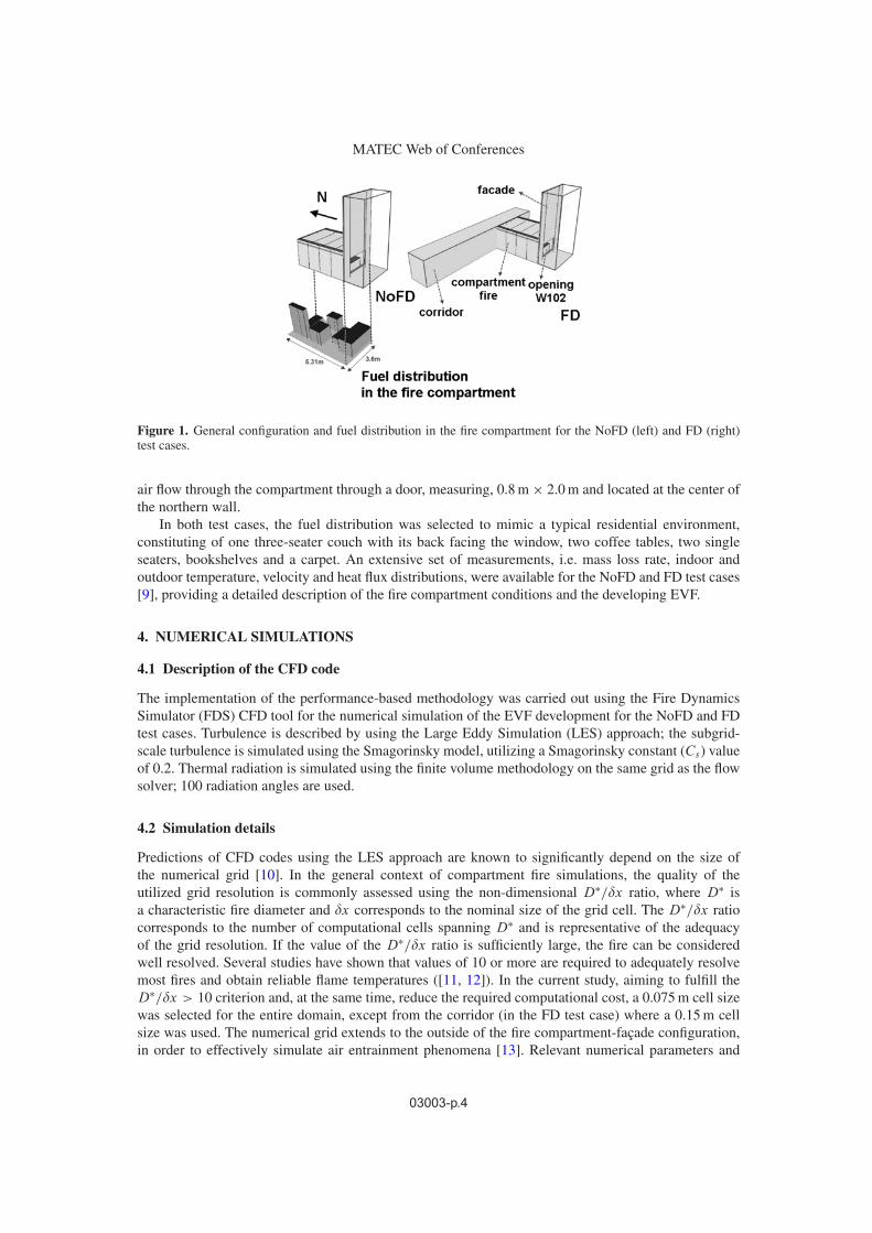
Aiming to investigate the effect of ventilation conditions to the development of an EVF from a firecompartment, a set of relevant experimental results was selected from the literature ([8, 9]). Twodifferent experimental layouts have been chosen, as shown in Figure 1, representing NoFD and FDventilation conditions. The NoFD test case constitutes of a fire compartment-façade configuration,measuring 5.3 m × 3.6 m × 2.4 m (compartment) and 3.6 m × 7.5 m (facade) respectively, with a2.4 m × 1.5 m single opening (W102) placed at the center of the southern fire compartment wall,0.5 m above the floor. The fire compartment and façade were lined with 2 layers of 16 mm fire ratedplasterboards. In the FD test case, the same fire compartment is located next to a corridor, which allows
03003-p.3
MATEC Web of Conferences
Figure 1. General configuration and fuel distribution in the fire compartment for the NoFD (left) and FD (right)test cases.
air flow through the compartment through a door, measuring, 0.8 m × 2.0 m and located at the center ofthe northern wall.
In both test cases, the fuel distribution was selected to mimic a typical residential environment,constituting of one three-seater couch with its back facing the window, two coffee tables, two singleseaters, bookshelves and a carpet. An extensive set of measurements, i.e. mass loss rate, indoor andoutdoor temperature, velocity and heat flux distributions, were available for the NoFD and FD test cases[9], providing a detailed description of the fire compartment conditions and the developing EVF.
4. NUMERICAL SIMULATIONS
4.1 Description of the CFD code
The implementation of the performance-based methodology was carried out using the Fire DynamicsSimulator (FDS) CFD tool for the numerical simulation of the EVF development for the NoFD and FDtest cases. Turbulence is described by using the Large Eddy Simulation (LES) approach; the subgrid-scale turbulence is simulated using the Smagorinsky model, utilizing a Smagorinsky constant (Cs) valueof 0.2. Thermal radiation is simulated using the finite volume methodology on the same grid as the flowsolver; 100 radiation angles are used.
4.2 Simulation details
Predictions of CFD codes using the LES approach are known to significantly depend on the size ofthe numerical grid [10]. In the general context of compartment fire simulations, the quality of theutilized grid resolution is commonly assessed using the non-dimensional D∗/�x ratio, where D∗ isa characteristic fire diameter and �x corresponds to the nominal size of the grid cell. The D∗/�x ratiocorresponds to the number of computational cells spanning D∗ and is representative of the adequacyof the grid resolution. If the value of the D∗/�x ratio is sufficiently large, the fire can be consideredwell resolved. Several studies have shown that values of 10 or more are required to adequately resolvemost fires and obtain reliable flame temperatures ([11, 12]). In the current study, aiming to fulfill theD∗/�x > 10 criterion and, at the same time, reduce the required computational cost, a 0.075 m cell sizewas selected for the entire domain, except from the corridor (in the FD test case) where a 0.15 m cellsize was used. The numerical grid extends to the outside of the fire compartment-façade configuration,in order to effectively simulate air entrainment phenomena [13]. Relevant numerical parameters and
03003-p.4
1st International Seminar for Fire Safety of Facades, Paris (France), 2013
Table 1. Main parameters and initial conditions for the NoFD and FD test cases.
Parameter UnitTest Case
NoFD FDCorridor-Fire compartment door Closed Open
Opening W102 Open OpenTotal number of computational cells 285,768 314,928
Total simulation time (s) 1900 1900Wood equivalent fuel load (kg/m2) 28.32 26.36
Ambient temperature (◦C) 11 15.4Wind speed (m/s) 1.6 1.5
Wind direction NE NE
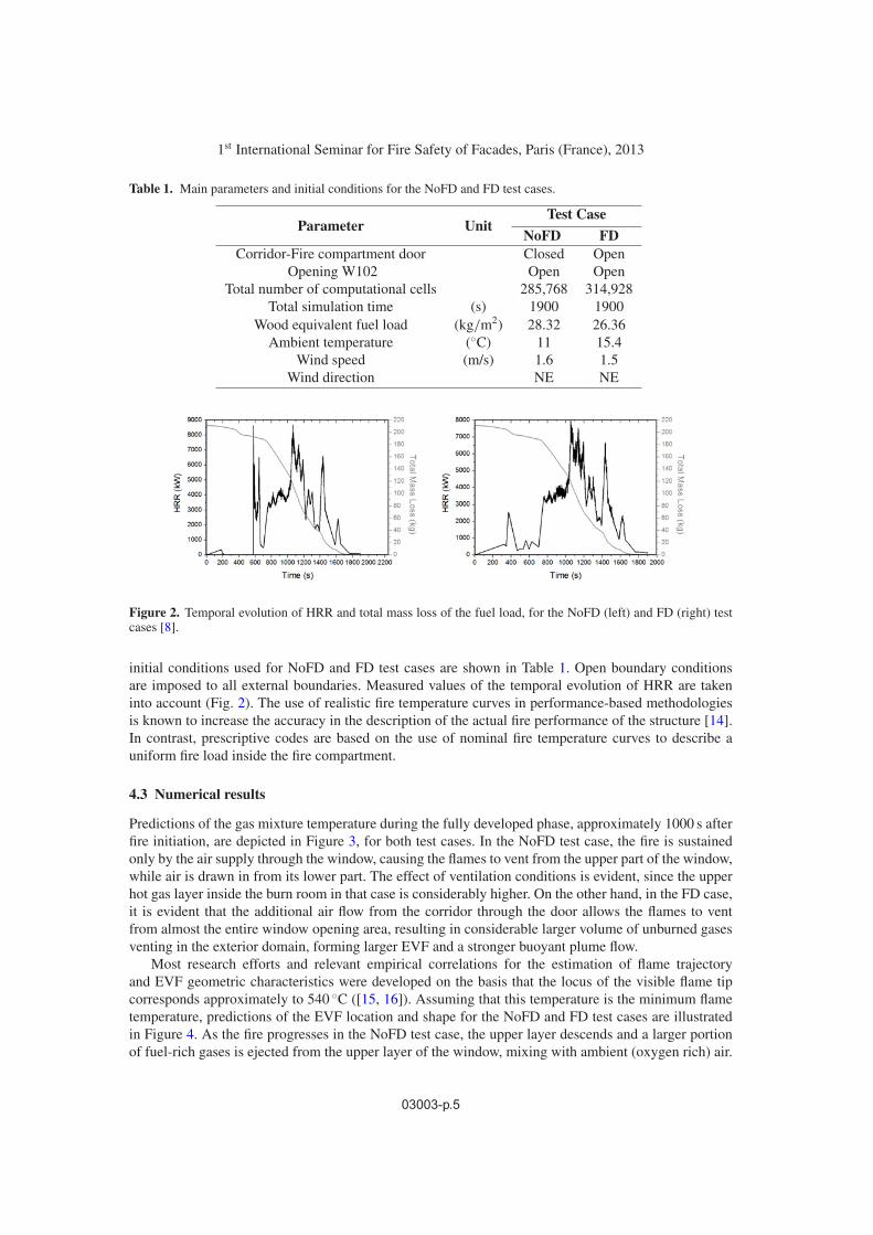
Figure 2. Temporal evolution of HRR and total mass loss of the fuel load, for the NoFD (left) and FD (right) testcases [8].
initial conditions used for NoFD and FD test cases are shown in Table 1. Open boundary conditionsare imposed to all external boundaries. Measured values of the temporal evolution of HRR are takeninto account (Fig. 2). The use of realistic fire temperature curves in performance-based methodologiesis known to increase the accuracy in the description of the actual fire performance of the structure [14].In contrast, prescriptive codes are based on the use of nominal fire temperature curves to describe auniform fire load inside the fire compartment.
4.3 Numerical results
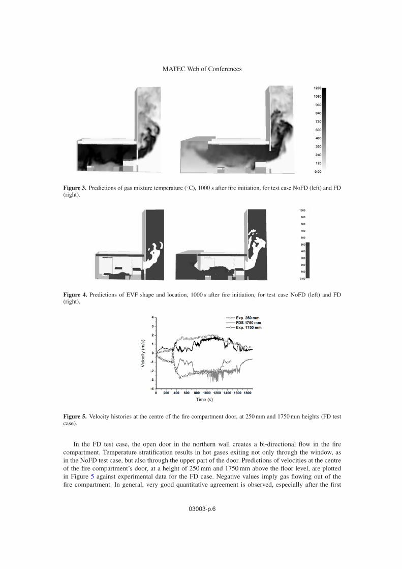
Predictions of the gas mixture temperature during the fully developed phase, approximately 1000 s afterfire initiation, are depicted in Figure 3, for both test cases. In the NoFD test case, the fire is sustainedonly by the air supply through the window, causing the flames to vent from the upper part of the window,while air is drawn in from its lower part. The effect of ventilation conditions is evident, since the upperhot gas layer inside the burn room in that case is considerably higher. On the other hand, in the FD case,it is evident that the additional air flow from the corridor through the door allows the flames to ventfrom almost the entire window opening area, resulting in considerable larger volume of unburned gasesventing in the exterior domain, forming larger EVF and a stronger buoyant plume flow.
Most research efforts and relevant empirical correlations for the estimation of flame trajectoryand EVF geometric characteristics were developed on the basis that the locus of the visible flame tipcorresponds approximately to 540 ◦C ([15, 16]). Assuming that this temperature is the minimum flametemperature, predictions of the EVF location and shape for the NoFD and FD test cases are illustratedin Figure 4. As the fire progresses in the NoFD test case, the upper layer descends and a larger portionof fuel-rich gases is ejected from the upper layer of the window, mixing with ambient (oxygen rich) air.
03003-p.5
MATEC Web of Conferences
Figure 3. Predictions of gas mixture temperature (◦C), 1000 s after fire initiation, for test case NoFD (left) and FD(right).
Figure 4. Predictions of EVF shape and location, 1000 s after fire initiation, for test case NoFD (left) and FD(right).
Figure 5. Velocity histories at the centre of the fire compartment door, at 250 mm and 1750 mm heights (FD testcase).
In the FD test case, the open door in the northern wall creates a bi-directional flow in the firecompartment. Temperature stratification results in hot gases exiting not only through the window, asin the NoFD test case, but also through the upper part of the door. Predictions of velocities at the centreof the fire compartment’s door, at a height of 250 mm and 1750 mm above the floor level, are plottedin Figure 5 against experimental data for the FD case. Negative values imply gas flowing out of thefire compartment. In general, very good quantitative agreement is observed, especially after the first
03003-p.6
1st International Seminar for Fire Safety of Facades, Paris (France), 2013
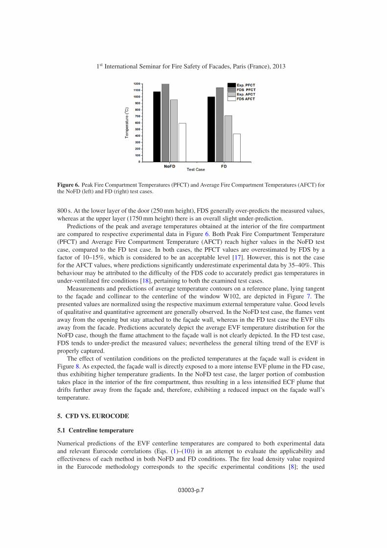
Figure 6. Peak Fire Compartment Temperatures (PFCT) and Average Fire Compartment Temperatures (AFCT) forthe NoFD (left) and FD (right) test cases.
800 s. At the lower layer of the door (250 mm height), FDS generally over-predicts the measured values,whereas at the upper layer (1750 mm height) there is an overall slight under-prediction.
Predictions of the peak and average temperatures obtained at the interior of the fire compartmentare compared to respective experimental data in Figure 6. Both Peak Fire Compartment Temperature(PFCT) and Average Fire Compartment Temperature (AFCT) reach higher values in the NoFD testcase, compared to the FD test case. In both cases, the PFCT values are overestimated by FDS by afactor of 10–15%, which is considered to be an acceptable level [17]. However, this is not the casefor the AFCT values, where predictions significantly underestimate experimental data by 35–40%. Thisbehaviour may be attributed to the difficulty of the FDS code to accurately predict gas temperatures inunder-ventilated fire conditions [18], pertaining to both the examined test cases.
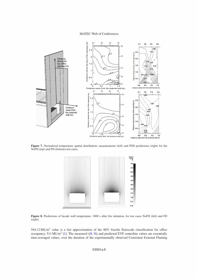
Measurements and predictions of average temperature contours on a reference plane, lying tangentto the façade and collinear to the centerline of the window W102, are depicted in Figure 7. Thepresented values are normalized using the respective maximum external temperature value. Good levelsof qualitative and quantitative agreement are generally observed. In the NoFD test case, the flames ventaway from the opening but stay attached to the façade wall, whereas in the FD test case the EVF tiltsaway from the facade. Predictions accurately depict the average EVF temperature distribution for theNoFD case, though the flame attachment to the façade wall is not clearly depicted. In the FD test case,FDS tends to under-predict the measured values; nevertheless the general tilting trend of the EVF isproperly captured.
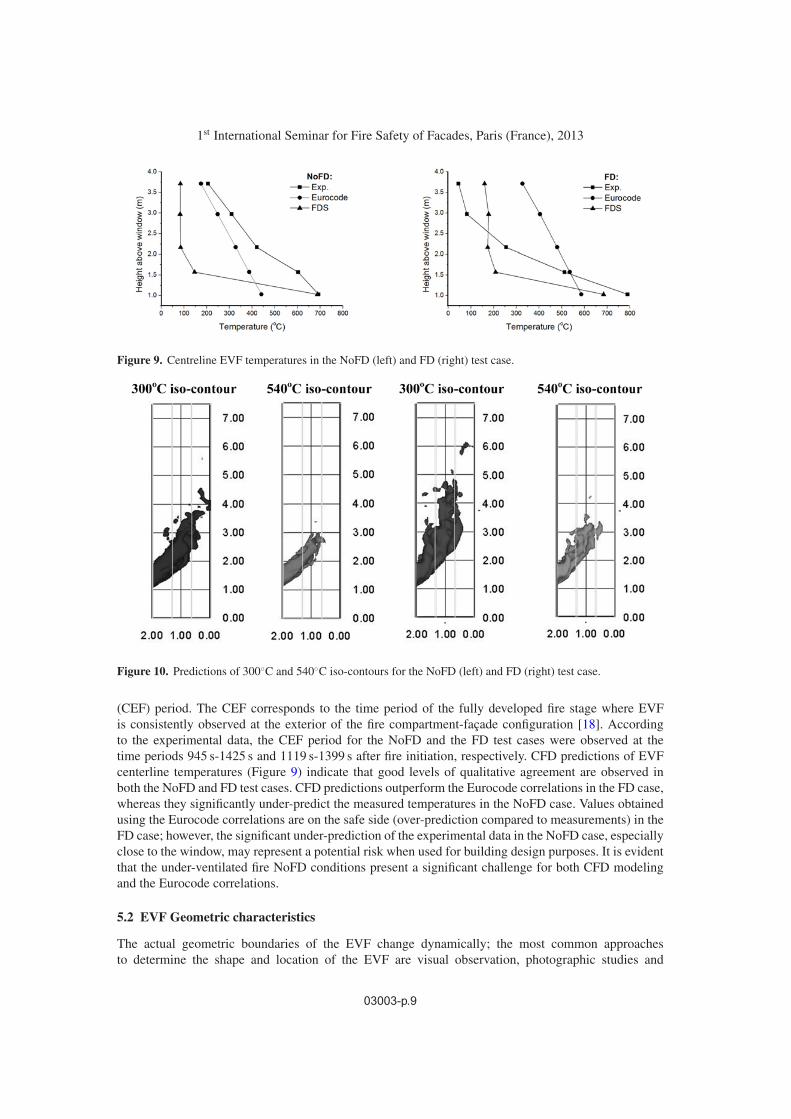
The effect of ventilation conditions on the predicted temperatures at the façade wall is evident inFigure 8. As expected, the façade wall is directly exposed to a more intense EVF plume in the FD case,thus exhibiting higher temperature gradients. In the NoFD test case, the larger portion of combustiontakes place in the interior of the fire compartment, thus resulting in a less intensified ECF plume thatdrifts further away from the façade and, therefore, exhibiting a reduced impact on the façade wall’stemperature.
5. CFD VS. EUROCODE
5.1 Centreline temperature
Numerical predictions of the EVF centerline temperatures are compared to both experimental dataand relevant Eurocode correlations (Eqs. (1)–(10)) in an attempt to evaluate the applicability andeffectiveness of each method in both NoFD and FD conditions. The fire load density value requiredin the Eurocode methodology corresponds to the specific experimental conditions [8]; the used
03003-p.7
MATEC Web of Conferences
Figure 7. Normalized temperature spatial distribution; measurements (left) and FDS predictions (right) for theNoFD (top) and FD (bottom) test cases.
Figure 8. Predictions of facade wall temperature, 1000 s after fire initiation, for test cases NoFD (left) and FD(right).
544.12 MJ/m2 value is a fair approximation of the 80% fractile Eurocode classification for officeoccupancy, 511 MJ/m2 [1]. The measured ([8, 9]) and predicted EVF centerline values are essentiallytime-averaged values, over the duration of the experimentally observed Consistent External Flaming
03003-p.8
1st International Seminar for Fire Safety of Facades, Paris (France), 2013
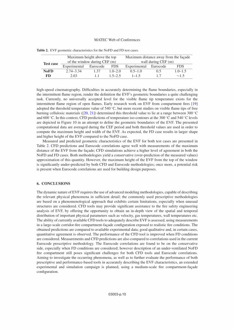
Figure 9. Centreline EVF temperatures in the NoFD (left) and FD (right) test case.
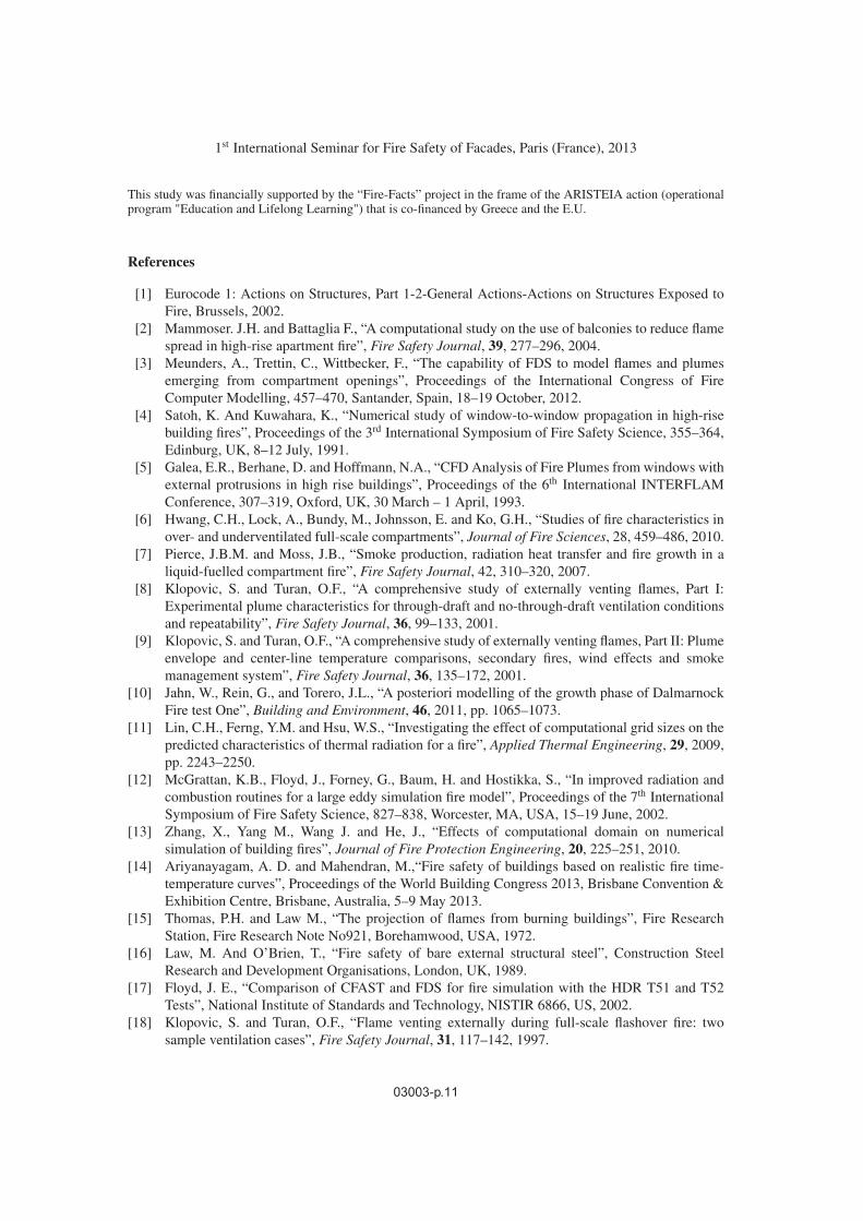
Figure 10. Predictions of 300◦C and 540◦C iso-contours for the NoFD (left) and FD (right) test case.
(CEF) period. The CEF corresponds to the time period of the fully developed fire stage where EVFis consistently observed at the exterior of the fire compartment-façade configuration [18]. Accordingto the experimental data, the CEF period for the NoFD and the FD test cases were observed at thetime periods 945 s-1425 s and 1119 s-1399 s after fire initiation, respectively. CFD predictions of EVFcenterline temperatures (Figure 9) indicate that good levels of qualitative agreement are observed inboth the NoFD and FD test cases. CFD predictions outperform the Eurocode correlations in the FD case,whereas they significantly under-predict the measured temperatures in the NoFD case. Values obtainedusing the Eurocode correlations are on the safe side (over-prediction compared to measurements) in theFD case; however, the significant under-prediction of the experimental data in the NoFD case, especiallyclose to the window, may represent a potential risk when used for building design purposes. It is evidentthat the under-ventilated fire NoFD conditions present a significant challenge for both CFD modelingand the Eurocode correlations.
5.2 EVF Geometric characteristics
The actual geometric boundaries of the EVF change dynamically; the most common approachesto determine the shape and location of the EVF are visual observation, photographic studies and
03003-p.9
MATEC Web of Conferences
Table 2. EVF geometric characteristics for the NoFD and FD test cases.
Maximum height above the top Maximum distance away from the façade
Test case of the window during CEF (m) wall during CEF (m)Experimental Eurocode FDS Experimental Eurocode FDS
NoFD 2.74–3.34 1.37 1.0–2.0 0.5–1.0 0.5 1.0–1.5FD 2.03 1.1 1.5–2.5 1–1.5 1.7 ∼1.5
high-speed cinematography. Difficulties in accurately determining the flame boundaries, especially inthe intermittent flame region, render the definition the EVF’s geometric boundaries a quite challengingtask. Currently, no universally accepted level for the visible flame tip temperature exists for theintermittent flame region of open flames. Early research work on EVF from compartment fires [19]adopted the threshold temperature value of 540 ◦C, but more recent studies on visible flame tips of freeburning cellulosic materials ([20, 21]) determined this threshold value to lie at a range between 300 ◦Cand 600 ◦C. In this context, CFD predictions of temperature iso-contours at the 300 ◦C and 540 ◦C levelsare depicted in Figure 10 in an attempt to define the geometric boundaries of the EVF. The presentedcomputational data are averaged during the CEF period and both threshold values are used in order tocompute the maximum height and width of the EVF. As expected, the FD case results in larger shapeand higher height of the EVF compared to the NoFD case.
Measured and predicted geometric characteristics of the EVF for both test cases are presented inTable 2. CFD predictions and Eurocode correlations agree well with measurements of the maximumdistance of the EVF from the façade; CFD simulations achieve a higher level of agreement in both theNoFD and FD cases. Both methodologies yield a conservative (over-prediction of the measured values)approximation of this quantity. However, the maximum height of the EVF from the top of the windowis significantly under-predicted by both CFD and Eurocode methodologies; once more, a potential riskis present when Eurocode correlations are used for building design purposes.
6. CONCLUSIONS
The dynamic nature of EVF requires the use of advanced modeling methodologies, capable of describingthe relevant physical phenomena in sufficient detail; the commonly used prescriptive methodologiesare based on a phenomenological approach that exhibits certain limitations, especially when unusualstructures are considered. CFD tools may provide significant assistance to the fire safety engineeringanalysis of EVF, by offering the opportunity to obtain an in-depth view of the spatial and temporaldistribution of important physical parameters such as velocity, gas temperatures, wall temperatures etc.The ability of currently available CFD tools to adequately describe EVF is assessed, using measurementsin a large-scale corridor-fire compartment-façade configuration exposed to realistic fire conditions. Theobtained predictions are compared to available experimental data; good qualitative and, in certain cases,quantitative agreement is observed. The performance of the CFD tool is improved when FD conditionsare considered. Measurements and CFD predictions are also compared to correlations used in the currentEurocode prescriptive methodology. The Eurocode correlations are found to be on the conservativeside, especially when FD conditions are considered; however description of an under-ventilated NoFDfire compartment still poses significant challenges for both CFD tools and Eurocode correlations.Aiming to investigate the occurring phenomena, as well as to further evaluate the performance of bothprescriptive and performance-based tools in accurately describing the EVF characteristics, an extendedexperimental and simulation campaign is planned, using a medium-scale fire compartment-façadeconfiguration.
03003-p.10
1st International Seminar for Fire Safety of Facades, Paris (France), 2013
This study was financially supported by the “Fire-Facts” project in the frame of the ARISTEIA action (operationalprogram "Education and Lifelong Learning") that is co-financed by Greece and the E.U.
References
[1] Eurocode 1: Actions on Structures, Part 1-2-General Actions-Actions on Structures Exposed toFire, Brussels, 2002.
[2] Mammoser. J.H. and Battaglia F., “A computational study on the use of balconies to reduce flamespread in high-rise apartment fire”, Fire Safety Journal, 39, 277–296, 2004.
[3] Meunders, A., Trettin, C., Wittbecker, F., “The capability of FDS to model flames and plumesemerging from compartment openings”, Proceedings of the International Congress of FireComputer Modelling, 457–470, Santander, Spain, 18–19 October, 2012.
[4] Satoh, K. And Kuwahara, K., “Numerical study of window-to-window propagation in high-risebuilding fires”, Proceedings of the 3rd International Symposium of Fire Safety Science, 355–364,Edinburg, UK, 8–12 July, 1991.
[5] Galea, E.R., Berhane, D. and Hoffmann, N.A., “CFD Analysis of Fire Plumes from windows withexternal protrusions in high rise buildings”, Proceedings of the 6th International INTERFLAMConference, 307–319, Oxford, UK, 30 March – 1 April, 1993.
[6] Hwang, C.H., Lock, A., Bundy, M., Johnsson, E. and Ko, G.H., “Studies of fire characteristics inover- and underventilated full-scale compartments”, Journal of Fire Sciences, 28, 459–486, 2010.
[7] Pierce, J.B.M. and Moss, J.B., “Smoke production, radiation heat transfer and fire growth in aliquid-fuelled compartment fire”, Fire Safety Journal, 42, 310–320, 2007.
[8] Klopovic, S. and Turan, O.F., “A comprehensive study of externally venting flames, Part I:Experimental plume characteristics for through-draft and no-through-draft ventilation conditionsand repeatability”, Fire Safety Journal, 36, 99–133, 2001.
[9] Klopovic, S. and Turan, O.F., “A comprehensive study of externally venting flames, Part II: Plumeenvelope and center-line temperature comparisons, secondary fires, wind effects and smokemanagement system”, Fire Safety Journal, 36, 135–172, 2001.
[10] Jahn, W., Rein, G., and Torero, J.L., “A posteriori modelling of the growth phase of DalmarnockFire test One”, Building and Environment, 46, 2011, pp. 1065–1073.
[11] Lin, C.H., Ferng, Y.M. and Hsu, W.S., “Investigating the effect of computational grid sizes on thepredicted characteristics of thermal radiation for a fire”, Applied Thermal Engineering, 29, 2009,pp. 2243–2250.
[12] McGrattan, K.B., Floyd, J., Forney, G., Baum, H. and Hostikka, S., “In improved radiation andcombustion routines for a large eddy simulation fire model”, Proceedings of the 7th InternationalSymposium of Fire Safety Science, 827–838, Worcester, MA, USA, 15–19 June, 2002.
[13] Zhang, X., Yang M., Wang J. and He, J., “Effects of computational domain on numericalsimulation of building fires”, Journal of Fire Protection Engineering, 20, 225–251, 2010.
[14] Ariyanayagam, A. D. and Mahendran, M.,“Fire safety of buildings based on realistic fire time-temperature curves”, Proceedings of the World Building Congress 2013, Brisbane Convention &Exhibition Centre, Brisbane, Australia, 5–9 May 2013.
[15] Thomas, P.H. and Law M., “The projection of flames from burning buildings”, Fire ResearchStation, Fire Research Note No921, Borehamwood, USA, 1972.
[16] Law, M. And O’Brien, T., “Fire safety of bare external structural steel”, Construction SteelResearch and Development Organisations, London, UK, 1989.
[17] Floyd, J. E., “Comparison of CFAST and FDS for fire simulation with the HDR T51 and T52Tests”, National Institute of Standards and Technology, NISTIR 6866, US, 2002.
[18] Klopovic, S. and Turan, O.F., “Flame venting externally during full-scale flashover fire: twosample ventilation cases”, Fire Safety Journal, 31, 117–142, 1997.
03003-p.11

MATEC Web of Conferences
[19] Yokoi, S., “Study on the prevention of fire spread caused by hot upward current”, BuildingResearch Institute, Report No. 34, Japan, 1960.
[20] Inganson, H., “Two dimensional rack storage fires”, Proceedings of the 4th InternationalSymposium on Fire Safety Sciences, 1209–1220, Ottawa, Canada, 13–17 July, 1994.
[21] Sullivan, A.L., Ellis, P.F. and Knight, I.K., “A review of radiant heat flux models used in bushfireapplications”, International Journal of Wildland Fire, 12, 101–110, 2003.
03003-p.12

![Comparative Study on the Evaluation of Wind Load on ... · compared with the result obtained from CFD in ANSYS ... obtained by using CFD post processing. REFERENCES [1] Twinsy P](https://img.pdfslide.us/doc/110x75/5ea216d29a613520de0fa13e/comparative-study-on-the-evaluation-of-wind-load-on-compared-with-the-result.jpg)