Embed Size (px)
Citation preview
International Research Journal of Engineering and Technology (IRJET) e-ISSN: 2395-0056
Volume: 04 Issue: 12 | Dec-2017 www.irjet.net p-ISSN: 2395-0072
© 2017, IRJET | Impact Factor value: 6.171 | ISO 9001:2008 Certified Journal | Page 8
Comparative analysis of tool tip temperature using DEFORM2D and AdvantEdge
L.MamundiAzaath1, U.Natarajan2, E.Mohan3
1&3Assistant Professor, Department of Mechanical Engineering, Mount Zion College of Engineering and Technology, Pudukkottai, Tamilnadu, India
2Assoicate Professor, Department of Mechanical Engineering, AlagappaChettiar Government College of Engineering and Technology, Karaikudi, Tamil Nadu, India.
---------------------------------------------------------------------***---------------------------------------------------------------------Abstract -The finite element method simulation for the orthogonal cutting of Aluminium alloy 6061 has been used broadly in companies and academia to investigate the machining process. These effective machining simulations have compensation over the actual machining experiments because of saving machining time and operating expense. This paper makes an assessment between finite element packages (DEFORM 2D, and AdvantEdge FEM). In the end, a comparison of the obtained results is made regarding tool chip temperature was investigated. Johnson-Cook’s model was taken for a flow stress equation of the material. Tool nose radius plays a vital role to minimize the tool chip interface temperature between cutting tool and work piece material. Based on the simulation study different assumptions were made to minimize contact zone temperature Key Words: Machining, tool tip temperature, Finite element software,Deform2D, AdvantEdge
1. INTRODUCTION Machining is one of the important processes of manufacturing the parts with defined shape and exact dimension. Aluminium alloy 6061 is an Aluminium-based alloy due to their high electrical conductivity, thermal conductivity, corrosion resistance, and weldability properties it was mainly focus to utilize in Aircraft, marine fittings, transport Equipments and Drive shafts. Most of available studies concerning on cylindrical turning in spite of there are some the other process like facing grooving taper turning and thread cutting on a lathe. With the advancement of computer technology, the Finite Element Method (FEM) was extensively used in machining simulation. Many related investigations were carried out for machining simulation in and overseas. The implementation of finite element method in order to execute a machining simulation is to identify tool chip interface temperature in between tool and work piece. Orthogonal cutting of Ti-6Al-4V alloy was involved in finite element simulation to calculate the tool tip temperature by using DEFORM2D software. Coulomb friction value (µ)0.382 was taken in orthogonal cutting test. In his study saw-tooth type chip was found in fracture condition. In simulation study of milling operation the
ductile fracture value was identified as 0.1 Makota NIKOWA [1]. Yusu[2] examine the tool tip temperature of 17Cr5Ni5MoTi as a work piece and cutting tool material tungsten carbide during machining process.FEM model was developed by using DEFORM2D by changing convective heat transfer co-efficient, tool tip temperature was simulated. Tool chip interface temperature was considerably reduces with increase in convective heat transfer co-efficient. His study also shows there is no change in cutting force and thrust force by varying the value of convective heat transfer co-efficient. Rajamani[3] developed the finite element model to study the formation of chip, cutting load and temperature distribution throughout the machining of AISI 6150 steel. In his simulation study three level of cutting speed 140 m/min,200 m/min & 300 m/min was considered as the input variables. Coulomb friction value of 0.4 is considered as a fixed value for all the machining simulations. TiN+TiCN+Al2O3 coated insert and work piece contact zone temperature was suddenly increased at maximum cutting speed. Friction value plays a vital role to fix the cutting force, thrust force and chip geometry. Mankova[4] investigated the simulation study of machining AISI 1045 hardened steel. In his research he validates the values of cutting force by using experimental work and simulation method. In his approach, mixed oxide ceramics material used as a cutting tool. AdvantEdge software was utilized to make simulation study on machining. Result clearly shows that cutting force and transverse force acting on the ceramic cutting tool was rapidly decreases with increase in cutting speed. Eliochiappini[5] mainly focused on chip formation on the machining of Ti-6Al-4V.sinusoidal spindle speed variation and constant speed machining are the two different approaches introduced in dry machining and the same conditions are set in to simulation method to find tool interface temperature .work piece length of 25mm was taken in simulation study and also in dry machining, tool interface temperature recorded at the interval of one second. In his simulation study results of cutting forces and the effect of tool interface temperature are recorded
International Research Journal of Engineering and Technology (IRJET) e-ISSN: 2395-0056
Volume: 04 Issue: 12 | Dec-2017 www.irjet.net p-ISSN: 2395-0072
© 2017, IRJET | Impact Factor value: 6.171 | ISO 9001:2008 Certified Journal | Page 9
up to twenty seconds. By comparing the experimental results with simulation results, simulation results are very closer to experimental results.ADVANTEDGE,DEFORM2D and FORGE2D three different simulation packages are used to validate the values of cutting force, average strain for the machining of Ti6Al4VCorina Constantin[6].Taguchi technique was implemented in this simulation study by taking 9 trials by choosing L9 orthogonal array. Cutting insert shape, relief angle, Nose radius was taken as the control parameters in his study. Finally Tamizharasan[7] concluded the optimum results of minimized temperature, wear depth, interface pressure are obtained by using ‘D’ shape tool relief angle of 00 and having the nose radius of 0.8mm.For getting improved results when machining AISI 1045 steel, cutting tool is very beneficial having less built-in angle and medium nose radius. De-WengTANG[8]study the outcome of residual stresses, cutting forces and tool tip temperature while machining SiCp/Al composites. Various combinations of feed rate and cutting speed are involved in simulation method using DEFORM-2D.Tool edge was meshed with the size range of 310-6 m before simulation. Environment temperature 200c ,coefficient of friction of 0.6 was assigned to the work piece in simulation environment. Tool force and temperature was analyzed by simulation by creating finite element model with tool radius 0.05mm, 0.1mm, 0.15mm, 0.2mm and 0.25mm. Finally he concluded that cutting tool force gradually increased with maximum of 0.25mm and at the same time tool temperature was found maximum at minimum corner radius of 0.05mm. Asit Kumar Parida[9] analyzed the contribution of nose radius in calculating forces, cutting temperature, chip thickness and chip tool contact through finite element analysis software. They used Inconel 718 round bar with diameter 50 mm and length 300mm for simulation study. In this study 6000c temperature was maintained at the outer surface of the work piece after that, the cutting force thrust force, chip thickness, chip contact length was measured in experiment mode. Same conditions are set in simulation environment and the output values are also taken in analytical manner. In his research maximum error percentage between simulation and analysis values are not more than 15 in chip contact length, chip thickness, and chip temperature was observed. Balazszsoltfarkas[10] concentrate on the tool geometry to developing the finite element mode to find stress and temperature development for the machining of 52HRC hard H-13 hardened steel. In his research he selected low content CBN as a cutting tool material and the work piece was meshed with 5319 elements. Simulation results obviously show that maximum stress in the tool obtained very near to the tool nose and he pointed out the values of these stresses lead to decrease the tool life.
2. MATERIAL MODELING: Machining is considered as the most important process which makes notable changes occurring in geometry for the machined work piece, DEFORM2D and advantEdgeare the two finite element software are selected due to consume time and machining cost compared with experimental work. Moreover from the study of research papers regarding with simulation modeling their simulation results closer to the experimental results. The numerical model was developed in DEFORM2D and AdvantEdge with Al6061 as work piece material and CBN as a cutting tool. To run the simulation, cutting speed and feed was taken as fixed value by changing the nose radius as 0.04mm, 0.045mm, 0.05mm and 0.055mm. 2.1 Material constitutive law D.R. Lesuer[11] propose that Johnson-cook constitutive law is used to develop finite element simulations, which can sufficiently represent the deformation response during high rate loading relation with large strains as well as moderate changes in strain rate and temperature. Modified Johnson-cook model is empirically based and signify the flow stress as shown in Eq.(1)
(1)
Table 1. Johnson- cook model parameters [11]
A(Mpa) B (Mpa) N C M 324 114 0.42 0.002 1.34
Table 1 represents the material constants for Aluminium 6061 and the chemical composition of the workpiece material is given in Table 2
Table 2: Chemical composition of AL6061
Ma
gn
esi
um
sili
con
iro
n
cop
pe
r
Zin
c
Tit
an
ium
Ma
ng
an
es
e
Ch
rom
ium
Alu
min
um
0.8-
1.2
0.4-
0.8
0.7
0.15-
0.40
0.25
0.15
0.15
0.04-
0.35
Remainder
3. FINITE ELEMENT MODELING DETAILS
Table 3: Process parameters
Parameter Value Initial temperature
20[◦C]
Cutting speed 150 [m/min] Feed 0.1 [mm/rev] Tool tip radius 0.04mm 0.045mm 0.05mm 0.055mm
International Research Journal of Engineering and Technology (IRJET) e-ISSN: 2395-0056
Volume: 04 Issue: 12 | Dec-2017 www.irjet.net p-ISSN: 2395-0072
© 2017, IRJET | Impact Factor value: 6.171 | ISO 9001:2008 Certified Journal | Page 10
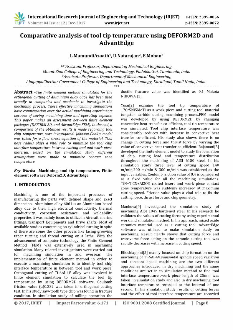
In this research two different software DEFORM 2D and AdvantEdge software have been utilized to simulate the orthogonal metal cutting process of aluminium alloy 6601 by using Tungsten carbide as a cutting tool material. Fig. 1 shows the improved FEM model of the orthogonal metal cutting process. In this simulation adaptive mesh technique has been used to create finite element model. The tool is fixed and the work piece is assumed to move along the cutting direction. The work piece dimension was assigned length 5 mm and height of 0.7 mm in the model. Initial temperatures of tool and work piece are 20c.
Fig.1Developed FEM model
4. SIMULATION STUDY In the first stage of simulation material behavior law can be introduced in to the finite element software DEFORM2D and AdvantEdge. In meshing element number was set for work piece and tool as 5300 and 3000 respectively. This simulation studies were carried out in four cases by using four different tool tip radius of 0.04mm, 0.045mm, 0.05mm and 0.055mm the clearance angle remaining constant at 15. From this simulation different kind of output parameters can be obtained such as tool tip temperature variation in chip, cutting forces etc. fixing the constant values of cutting speed, feed by varying the values of tool tip radius tool interface temperature and chip morphology was found. After finding the results by using DEFORM2D and AdvantEdge comparative analysis was made.
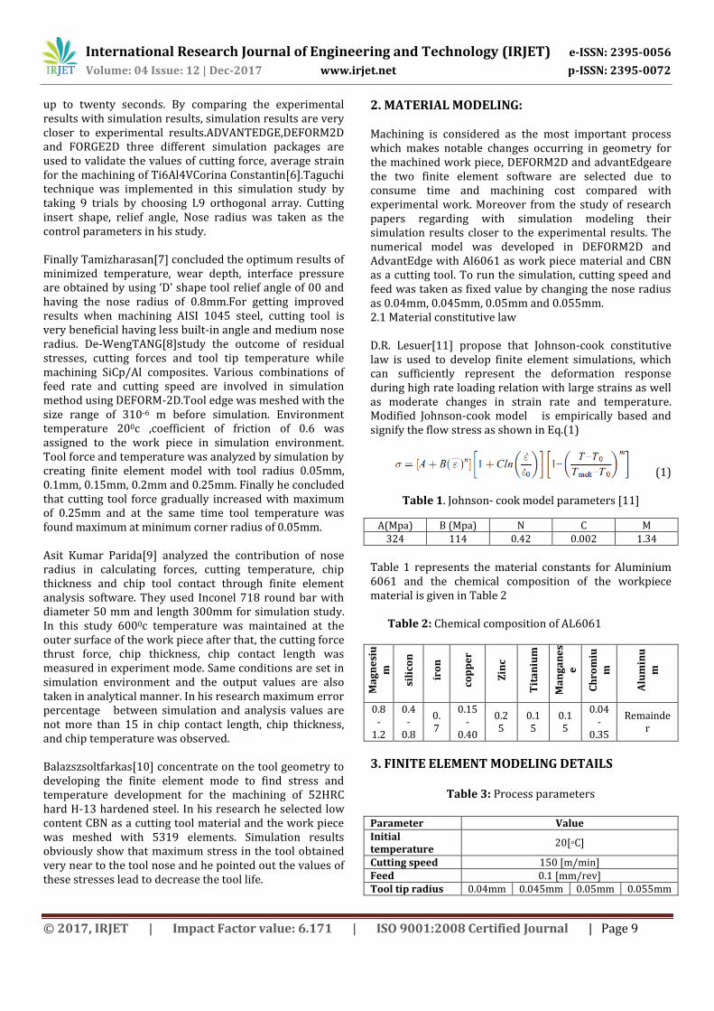
5. RESULTS AND DISCUSSION The effect of nose radius in cutting tool by using DEFORM2D and AdvantEdge software are discussed. The tool chip interface temperature between cutting tool and work piece was indicated from the figure 2 to figure.5 by using DEFORM2D.AdvantEdgefinite model shows the tool tip temperature prediction values from figure.6 to figure.9.From the study of prediction model of tool chip interface temperature gives the information was given below in the DEFORM2D model, from the tool nose radius
of 0.04mm the tool chip interface temperature was identified as 127.072 c When the tool nose radius was increased to 0.055mm the tool chip interface temperature becomes 126.29c. In the AdvantEdge model the maximum tool chip interface temperature 136.907c was identified at the tool nose radius of 0.04mm. The minimum tool chip interface temperature 135.421c was attained at the tool nose radius of 0.05mm.
Fig.2. Tool interface temperature at nose radius of 0.04mm
Fig.3. Tool interface temperature at nose radius of 0.045mm
Fig.4.Tool interface temperature at nose radius of 0.05mm
International Research Journal of Engineering and Technology (IRJET) e-ISSN: 2395-0056
Volume: 04 Issue: 12 | Dec-2017 www.irjet.net p-ISSN: 2395-0072
© 2017, IRJET | Impact Factor value: 6.171 | ISO 9001:2008 Certified Journal | Page 11
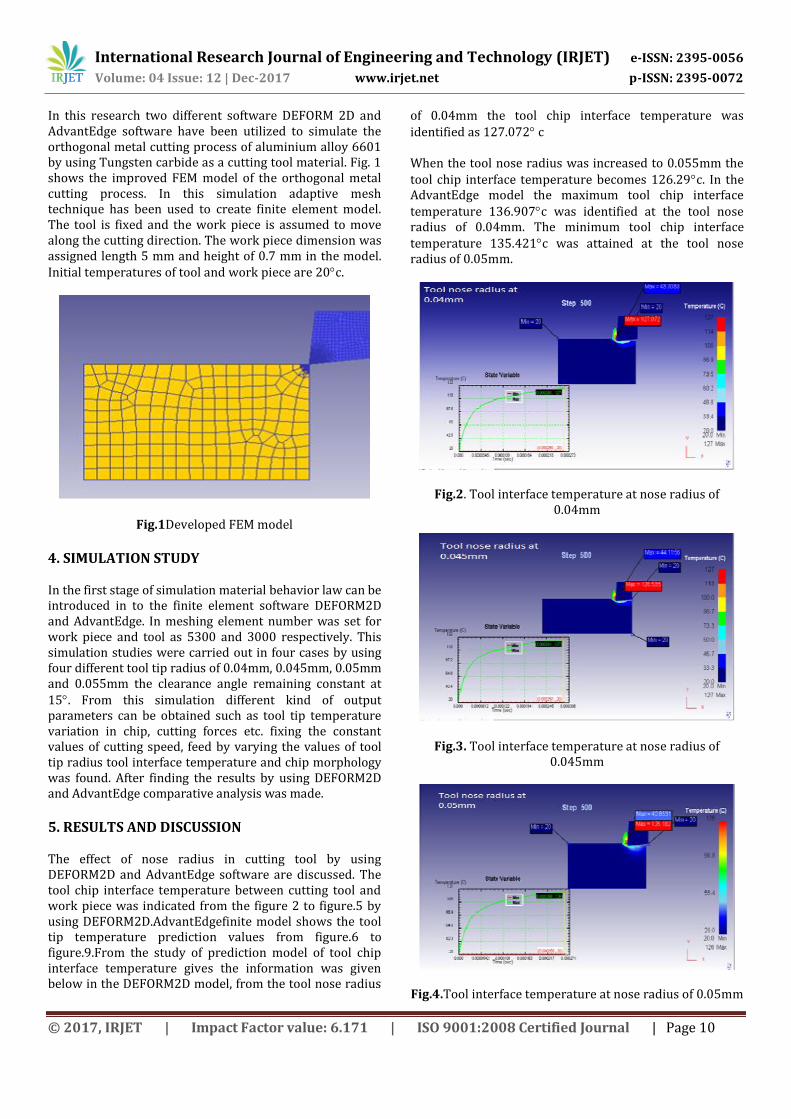
Fig.5. Tool interface temperature at nose radius of 0.055mm
Fig.6. Tool interface temperature at nose radius of 0.04mm in AdvantEdge software.
Fig.7. Tool interface temperature at nose radius of 0.045mm in AdvantEdge software.
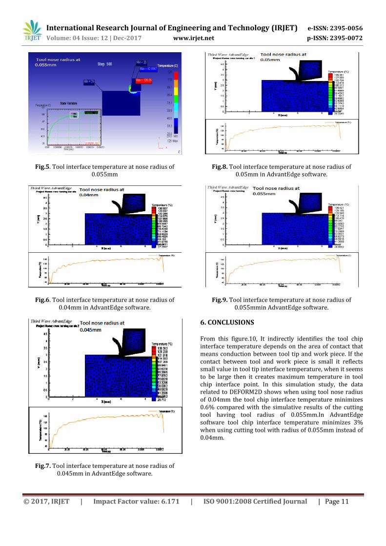
Fig.8. Tool interface temperature at nose radius of 0.05mm in AdvantEdge software.
Fig.9. Tool interface temperature at nose radius of 0.055mmin AdvantEdge software.
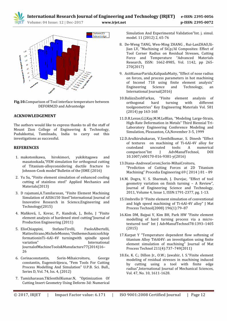
6. CONCLUSIONS From this figure.10, It indirectly identifies the tool chip interface temperature depends on the area of contact that means conduction between tool tip and work piece. If the contact between tool and work piece is small it reflects small value in tool tip interface temperature, when it seems to be large then it creates maximum temperature in tool chip interface point. In this simulation study, the data related to DEFORM2D shows when using tool nose radius of 0.04mm the tool chip interface temperature minimizes 0.6% compared with the simulative results of the cutting tool having tool radius of 0.055mm.In AdvantEdge software tool chip interface temperature minimizes 3% when using cutting tool with radius of 0.055mm instead of 0.04mm.
International Research Journal of Engineering and Technology (IRJET) e-ISSN: 2395-0056
Volume: 04 Issue: 12 | Dec-2017 www.irjet.net p-ISSN: 2395-0072
© 2017, IRJET | Impact Factor value: 6.171 | ISO 9001:2008 Certified Journal | Page 12
Fig.10.Comparison of Tool interface temperature between DEFORM2D and Advantedge
ACKNOWLEDGEMENT The authors would like to express thanks to all the staff of Mount Zion College of Engineering & Technology, Pudukkottai, Tamilnadu, India to carry out this investigations as successful.
REFERENCES
1. makotonikawa, hirokimori, yukikitagawa and masatookada,“FEM simulation for orthogonal cutting of Titanium-alloyconsidering ductile fracture to Johnson-Cook model”Bulletin of the JSME (2016)
2. Yu Su, “Finite element simulation of enhanced cooling cutting of stainless steel” Applied Mechanics and Materials(2013)
3. D rajamani,A.Tamilarasan, “Finite Element Machining Simulation of AISI6150 Steel”International Journal of Innovative Research in Science,Engineering and Technology(2015)
4. Maňková, I., Kovac, P., Kundrak, J., Beňo, J “Finite element analysis of hardened steel cutting”Journal of Production Engineering (2011)
5. ElioChiappini, StefanoTirelli, PaoloAlbertelli, MatteoStrano,MicheleMonno,“OnthemechanicsofchipformationinTi–6Al–4V turningwith spindle speed variation” International JournalofMachineTools&Manufacture77(2014)16–26
6. Corinaconstantin, Sorin-Mihaicroitoru, George constantin, Eugenstrăjescu, “Fem Tools For Cutting Process Modelling And Simulation” U.P.B. Sci. Bull., Series D, Vol. 74, Iss. 4, (2012)
7. Tamizharasan.T&SenthilKumar.N, “Optimization Of Cutting Insert Geometry Using Deform-3d: Numerical
Simulation And Experimental Validation”Int. j. simul. model. 11 (2012) 2, 65-76
8. De-Weng TANG, Wen-Ming ZHANG , Rui-LanZHAO,Xi-Jian LV, “Machining of SiCp/Al Composites: Effect of Tool Corner Radius on Residual Stresses, Cutting Force and Temperature “Advanced Materials Research, ISSN: 1662-8985, Vol. 1142, pp 265-270(2017)
9. AsitKumarParida,KalipadaMaity, “Effect of nose radius on forces, and process parameters in hot machining of Inconel 718 using finite element analysis” Engineering Science and Technology, an International Journal(2016)
10. BalázsZsoltFarkas, “Finite element analysis of orthogonal hard turning with different toolgeometries” Key Engineering Materials Vol. 581 (2014) pp 163-168
11. D.R.Lesue,G.J.Kay,M.M.LeBlan, “Modeling Large-Strain, High-Rate Deformation in Metals” Third Biennial Tri-Laboratory Engineering Conference Modeling and Simulation, Pleasanton, CA,November 3-5, 1999
12. D.Arulkirubakaran, V.Senthilkumar, S. Dinesh “Effect of textures on machining of Ti-6Al-4V alloy for coatedand uncoated tools: A numerical comparison”Int J AdvManufTechnol, DOI 10.1007/s00170-016-9381-y(2016)
13. Diana–AndreeaCoroni,Sorin-MihaiCroitoru, “Prediction of Cutting Forces at 2D Titanium Machining” Procedia Engineering 69 ( 2014 ) 81 – 89
14. M. Dogra, V. S. Sharmab, J. Durejac, “Effect of tool geometry variation on finish turning – A Review”, Journal of Engineering Science and Technology, 2011, Volume 4, Issue 1, ISSN:1791-2377, pg. 1-13.
15. Umbrello D “Finite element simulation of conventional and high speed machining of Ti-6Al-4V alloy” J Mat Process Technol(2008) 196(1):79–87
16. Kim DM, Bajpai V, Kim BH, Park HW “Finite element modelling of hard turning process via a micro-textured tool” Int J AdvManufTechnol78:1393–1405 (2015)
17. Karpat Y “Temperature dependent flow softening of titanium Alloy Ti6Al4V: an investigation using finite element simulation of machining” Journal of Mat Process Technol 211(4):737–749(2011)
18. Ee, K. C.; Dillon Jr., O.W.; Jawahir, I. S.“Finite element modeling of residual stresses in machining induced by cutting using a tool with finite edge radius”,International Journal of Mechanical Sciences, Vol. 47, No. 10, 1611-1628.