Embed Size (px)
Citation preview

COMPACTE
Electric Boilers
TECHNICAL MANUAL
PO Box 11 Ashton Under Lyne OL6 7TR +44. (0) 161 621 5960 Fax +44. (0) 161 621 5966
[email protected] www.atlanticboilers.com

2

3
CONTENTS
DESCRIPTION………….………………………………...……………………………………1
SCHEMATIC………………………………………………………………………………….…3
COMMAND ELECTRIC DIAGRAM…………………..……………….……………………5
POWER ELECTRIC DIAGRAM…………………….……………………………….………8
STARTING THE BOILER…………………………………………………..……………………………..9
INSTALLATION……………………………………………………………………………….10
SERVICING…………………………………………………………………………………….11
THE COMMISSIONING OF THE COMPACTE……………………………………………27
THE GUARANTEE ON THE COMPACTE………………………………………………….32
PO Box 11 Ashton Under Lyne OL6 7TR +44. (0) 161 621 5960 Fax +44. (0) 161 621 5966
[email protected] www.atlanticboilers.com
4
5
7
8
9
11
12
13
14

4
DESCRIPTION
The “Compacte” electric boilers have been designed for any heating system (maximum working pressure 4 Bars)
• Electric boilers from 36 to 72 kW, with integrated internal electrical wiring, for closed heating system without antifreeze, with clean and neutral water.
• Main body: Steel FE 360 B • Volume: 70litres • Weight: 120kg • Maximum flow temperature: 99ºC • Safety Thermostat (100ºC) • 50 mm rockwool insulation • Flow/Return connections sizes: 50
Minimum flow: 3.5m³ / H Maximum flow: 10m³ / H Resistance through the boiler: 0.4m / ce or 4 kPA
1. Control Panel 2. Ventilation 3. Flow 4. Boiler sensors pocket 5. Immersion Heaters 6. Insulation 7. Return 8. Power (Main) 9. Electrical components 10. On/Off main switch

5
SCHEMATIC
1) Conventional Pipework
2) Weather compensated Pipework 3) Weather compensated pipework
Radiators or under-floor heating

6
4) Heating and hot water pipework
NB: Boiler pump flow should be 5% superior to the sum of heating and DHW primary pump
expansion vessel
pressure & temperature relief
valve
3 port valve
auto air vent
pump
non return valve
Fill loop
pressure relief valve
isolating ball valve
Radiators
7
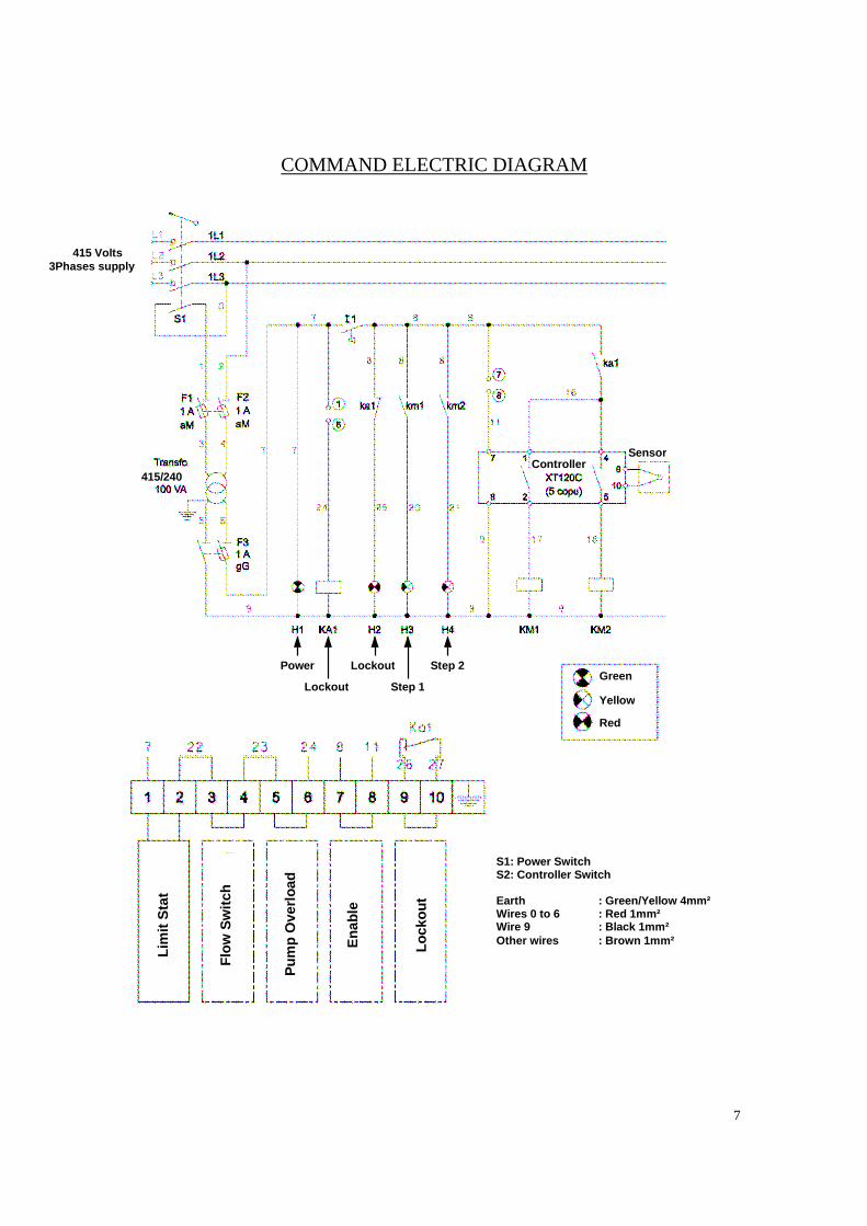
COMMAND ELECTRIC DIAGRAM
415 Volts 3Phases supply
415/240 Controller
Sensor
Step 2
Step 1 Lockout
Lockout Power Green
Yellow
Red
Lim
it S
tat
Flo
w S
witc
h
Pum
p O
verlo
ad
Ena
ble
Lock
out
S1: Power Switch S2: Controller Switch Earth : Green/Yellow 4mm² Wires 0 to 6 : Red 1mm² Wire 9 : Black 1mm² Other wires : Brown 1mm²

8
POWER ELECTRIC DIAGRAM
Fuses:
F1-F2-F3: Industrial cylinder cartridge (8,5 * 31,5) • • F1: 1A type AM F2: 1A type AM F3: 1A type gG F6-F7: Industrial cylinder cartridge (22 * 58)
36 kW 48 kW 60 W 72 kWF6 50 A 50 A 63 A 63 A
KM1 24 kW 24 kW 36 kW 36 kWF7 25 A 50 A 50 A 63 A
KM2 12 kW 24 kW 24 kW 36 kW
415V. 3 ph
Stage 1
Stage 2

9
STARTING THE BOILER
• Check that the system is filled with water • Purge the system • An automatic air vent is required on the flow from the boiler • Power the boiler • Switch the boiler on • Set the two regulation stages • If the boiler is powered without any water, it will cause the immersion heaters or
sensors to fail (no warranty) Controls
Factory settings (stage 1: 80ºC, stage 2: 75ºC)
Adjustment Nota: + Set 1 = Stage 1 Set 2 = Stage 2 + Set 1 must always be > Set 2 + Minimum setting temperature +20ºC + Maximum settings temperature +90ºC + Starting point stage 1: 3ºC under the setting temperature, with 3
minutes confirmation time + Starting point stage 2: 2ºC under the setting temperature, with 3
minutes confirmation time + Each stage to be stopped when the settings temperature has been
reached
1. Display 2. Stage selector (adjustment & control) 3. Settings + 4. Settings – 5. Operation light 6. Control stage light on 7. Alarm light

10
First Start: 3 minutes confirmation
A. Press the (2) key SET1 for 5 seconds, the (6) light shine B. Adjust the settings with (3) and (4) keys C. Validate by pressing the (2) key set1, the indicator (1) is flashing the new
stage 1 setting is stored, the (6) light switched off (after a few seconds the real temperature is shown on the display)
D. Press the (2) key SET 2, for the second stage for 5 seconds: the (6) light
shine
E. Adjust the settings with (3) and (4) keys F. Validate by pressing the (2) key SET 2, the (1) indicator is flashing, the
new stage 2 setting is stored, the (6) light switched off (after a few seconds the real temperature is shown on the display)
Alarm Signal Alarm light (7) on the (1) display shows:
• “000” Sensor default • “HA” High temperature limit stat alarm • “LA” Low temperature limit stat alarm

11
INSTALLATION
The electric boiler “compacte” should be installed in a louvered plantroom in order to ensure an ambient temperature below 30ºC and relative humidity between 30 and 80%. The boiler should not be used in a corrosive atmosphere or in an external position. Adequate access should be left around the boiler in order to carry out maintenance. The following safety devices are obligatory:
• Safety valve (4 Bars maximum) • An automatic air vent on the boiler flow • A blow down valve
Electrical wiring
The electric boiler “compacte” should be connected to 415V without neutral The circuit breaker and the cables section should be chosen according to British standards. Class 1 material IP21 / IK08 If the boiler is powered without any water, it will generate the thermocouple failure (no warrantee)
Transport and storage The unit should be transported and stored in the original package until it reached the installation point. Ambiant temperature below 80ºC Relative humidity between 30 and 80%

12
SERVICING
Loss of water velocity through the boiler can lead to temperature rise
• Consider a sediment vessel on the return to capture sediment deposit • Blocking immersion heaters irrigation can destroy them
NOTE : The immersion heaters can be destroyed by blockage of the water flow It is essential that a periodical cleaning is carried out on the main heat exchanger and the sensors. The water also needs to be clean without any antifreeze or scale remover product Removal of sludge and sediment reduce corrosion risks On first start: Check the electrical operation Check each terminal to avoid any contact resistance or temperature rise Activate the safety valve manually Monthly servicing Check
� The automatic air vent � The safety valve
Biannual servicing
Check each terminal to avoid any contact resistance or temperature rise

13
THE COMMISSIONING OF THE ATLANTIC COMPACTE
All Atlantic boilers and water heaters are thoroughly tested for mechanical, electrical and
combustion performance at the factory
The prime object of the site commissioning of the boiler(s) is, subject to installed
conditions, to match the optimum combustion performance results reached at the factory
and to ensure the boiler(s) is/are installed according to the conditions of guarantee.
The following check list should be satisfied before the commissioning takes place. To
arrange the commissioning Atlantic should be given a minimum of ten days notice of the
date and time required.
Commissioning sheet

14
THE GUARANTEE ON THE ATLANTIC COMPACTE
This guarantee is to the purchaser of the boiler(s) who is deemed to be the installer. If the boiler(s) is (are) purchased by the eventual user who then arranges to install the boiler(s), the eventual user is deemed to be the installer. The details of the guarantee are given to assist the installer in obtaining effective action within the guarantee and they are in addition to the installer’s legal rights under the relevant statutory enactments for the time being in force in England, Wales, and Scotland. Electrical equipment: The replacement or repair of the item, including the cost of its delivery to the site of the installation or its equal within England, Wales and Scotland, provided that the defect or flaw occurs within 1 calendar year of the commissioning date. Removable component of the boiler assembly (other than the electrical equipment) The replacement or repair of the item, including the cost of its delivery to the site of the installation or its equal within England Wales and Scotland if the defect or flaw occurs within 1 calendar year of the commissioning date. The main body of the boiler. The repair of any welding defects in the main body of the water heater including any necessary removal or replacement of that part of the water heater on site if the defect occurs within 3 calendar years of the commissioning date. Definitions: The effective actions stipulated in this guarantee are subject to the purchaser complying completely with the following:
1) The boilers are installed according to the recommendations of this technical booklet, the recommended codes of practice of the C.I.B.S.E and the B.S.I., and the checklist on page 13 is satisfied.
2) The commissioning of the boilers by ACM Atlantic and their regular annual servicing and maintenance.
3) The payment in full, by the purchaser unless otherwise agreed, of the invoice for the supply and delivery of the boiler(s) to site, any other relevant invoices connected with the boiler positioning and fixing, and the invoices for commissioning and any correction of installation error, all to be made within one calendar month of the date of the invoice.
4) The presentation, at the time of a claim under the guarantee, of the boiler registration number, the commissioning record with date, and the necessary information for defining any replacement part.
5) When a replacement item is supplied for a defective item, the defective item must be returned to ACM Atlantic at their registered office within 6 weeks of the date of notification of the defect carefully labeled with registration number of the boiler and the name and the order reference of the purchaser of the boiler. If this is not complied with, the purchaser will be charged with the cost of the item and its delivery.