Embed Size (px)
Citation preview
CompactBlock I/O for PROFIBUS DP1791P-16B0, 1791P-0B16P, 1791P-8B8P, 1791P-4B4P, 1791P-8V8P
Technical Data
1791P CompactBlock™ I/O modules are stand-alone 24V dc Block I/O products that communicate via a PROFIBUS DP link. Each PROFIBUS DP node consists of either one base module or one base module and one expansion module. Any expansion module can be coupled with any base module. CompactBlock 1791P consists of only base modules. The expansion modules are part of the CompactBlock 1791D family of products. CompactBlock PROFIBUS DP modules must be installed in a secondary enclosure. Base modules are equipped with 8 to 16 points. CompactBlock PROFIBUS DP provides sinking and sourcing inputs and outputs. Sinking inputs are 24V dc NEMA Type 3 compatible. Self-protected 24V dc outputs can provide up to 0.5 amp each.
CompactBlock I/O for PROFIBUS DP Base Modules and DeviceNet Expansion Modules
• 4 sinking input 4 sourcing output base module (1791P-4B4P)
• 8 sinking input/ 8 sourcing output base module (1791P-8B8P)
• 8 sourcing input/ 8 sinking output base module (1791P-8V8P)
• 16 sinking input base module (1791P-16B0)
• 16 sourcing output base module (1791P-0B16P)
• 16 sinking input expansion module (1791D-16B0X)
• 16 sourcing input expansion module (1791D-16V0X)
• 16 sourcing output expansion module (1791D-0B16PX)
• 16 sinking output expansion module (1791D-0V16PX)

2 Overview CompactBlock I/O for PROFIBUS DP
Important User Information Because of the variety of uses for the products described in this publication, those responsible for the application and use of these products must satisfy themselves that all necessary steps have been taken to assure that each application and use meets all performance and safety requirements, including any applicable laws, regulations, codes and standards. In no event will Rockwell Automation be responsible or liable for indirect or consequential damage resulting from the use or application of these products.
Any illustrations, charts, sample programs, and layout examples shown in this publication are intended solely for purposes of example. Since there are many variables and requirements associated with any particular installation, Rockwell Automation does not assume responsibility or liability (to include intellectual property liability) for actual use based upon the examples shown in this publication.
Allen-BradleyTM publication SGI-1.1, Safety Guidelines for the Application, Installation and Maintenance of Solid-State Control (available from your local Allen-Bradley office), describes some important differences between solid-state equipment and electromechanical devices that should be taken into consideration when applying products such as those described in this publication.
Reproduction of the contents of this copyrighted publication, in whole or part, without written permission of Rockwell Automation, is prohibited.
Publication 1791P-TD001B-EP - October 2002

CompactBlock I/O for PROFIBUS DP Overview 3
Overview CompactBlock I/O for PROFIBUS DP blocks are compatible with any PROFIBUS DP scanner.
To set the station address, lift the door containing the status LEDs on the top left side of the module. Adjust the switches located behind the door.
Benefits
• Base blocks have a built-in PROFIBUS adapter• Use GSD files to connect and configure• PROIFBUS DP conformance tested means high level of
interoperability with other PROFIBUS products• Mounts horizontally or vertically on DIN rail• cUL Listed, CE certified• Address switches and auto baud ease network commissioning• Hardware watchdog function secures state of I/O in case of failure• IEC/NEMA Type 3+ inputs offers widest range of compatible
sensors
Typical Configuration This illustration shows how CompactBlock I/O fits into a typical PROFIBUS system.
StatusNetwork
0 1 2 3 4 5 6 7 0 1 2 3 4 5 6 7
CompactBlock I/O1791P-8V8P
8 INPUTS / 8 OUTPUTS - DC POWER
Allen-Bradley
Profibus DP
Module
Status
5 6 7
CompactBlock I/O1791R-8V8P
8 INPUTS / 8 OUTPUTS - DC POWER
5 6 7
CompactBlock I/O1791R-8V8P
8 INPUTS / 8 OUTPUTS - DC POWER
5 6 7
CompactBlock I/O1791R-8V8P
8 INPUTS / 8 OUTPUTS - DC POWER
5 6 7
CompactBlock I/O1791R-8V8P
8 INPUTS / 8 OUTPUTS - DC POWER
5 6 7
CompactBlock I/O1791R-8V8P
8 INPUTS / 8 OUTPUTS - DC POWER
EXPANSION UNIT CompactCompactBlock LDX
PULLPULL PULLPULL
EXPANSION UNIT CompactCompactBlock LDX
PULLPULL PULLPULL
EXPANSION UNITANSION UNIT CompactCompactBlocBlock LDXk LDX
PULLPULL PULLPULLPULLPULL
43323
Personal Computer with configuration software
Sensor HMI
PLC-5 or other programmable controller
PowerFlex™ Drive
Interface
FlexArmor™
PROFIBUS Scanner
SLC or other controller
Field DeviceSensor
HMI
FLEX I/O™
1790P CompactBlock LDX I/O
Transmitter
ControlLogix™ or other programmable controller
PROFIBUS Scanner
Point I/O™
1791P CompactBlock I/O
Publication 1791P-TD001B-EP - October 2002

4 Overview CompactBlock I/O for PROFIBUS DP
System Compatibility CompactBlock I/O modules are compatible with any PROFIBUS DP scanner.
CompactBlock I/Oon PROFIBUS DP
Optimized for high speed and inexpensive installation, PROFIBUS DP (decentralized periphery) is designed especially for communication between programmable controllers (PLCs) and distributed I/O at the device level. Data exchange is mainly cyclic with field devices such as I/O, valves, drives and measuring transducers. The primary controller (master) reads the input information from the field devices (slaves) and sends the output information back to the slaves.The communication functions required for this are highlighted in the following table and are defined by the PROFIBUS standard.
Basic DP Functions
Data communication is monitored on both the master and slave sides.
Speed
PROFIBUS DP requires about 1 msec at 12 Mbit/sec to transmit 512 bits of input data and 512 bits of output data to 32 stations.
Bus Access • Token passing procedure between masters and master-slave procedure between master and slaves
• Mono-master or multi-master system possible• Master and slave devices, maximum 126 stations on one bus
Communication • Peer-to-peer (user data communication) or multicast (control commands)• Cyclic master-slave user data communication
Operating States • Operate - cyclic transmission of input and output data• Clear - inputs are read, outputs remain in secure state• Stop - diagnostics and parameterization, no user data transmission
Synchronization • Control commands allow the synchronization of inputs and outputs• Sync mode - outputs are synchronized• Freeze mode - inputs are synchronized
Functions • Cyclic user data transfer between DP master and slave• Dynamic activation or deactivation of individual slaves• Checking the configuration of the slaves• Powerful diagnostic functions, 3 hierarchical levels of diagnostic messages• Synchronization of input and/or outputs• Address assignment for slaves optionally possible via the bus• Maximum of 244 bytes input and output data possible for each slave
Protective Functions
• All messages are transmitted at a hamming distance of HD=4• Watchdog control of DP slave detects failure of the assigned master• Access protection for inputs/outputs of slaves• Monitoring of user data communication with adjustable monitoring timer
in the master
Device Types • DP master Class 2 (DPM2), e.g., engineering or diagnostics tool• DP master Class 1 (DPM1), e.g., central programmable controllers such as
PLC, SLC, PC• DP slave e.g., devices with binary or analog inputs/outputs, drives, valves
Publication 1791P-TD001B-EP - October 2002

CompactBlock I/O for PROFIBUS DP Overview 5
Diagnostics
Diagnostic messages are transmitted over the network and collected at the master and are classified into three types:• Station-related - status of the device (for example, low voltage or
over temperature, depending on the device).• Module-related - indicates if any of the connected I/O modules
report errors. More detailed information of the error can be found by evaluating the channel-related diagnostic message.
• Channel-related - provides information on channel errors of the I/O modules and expands on the module-related diagnostics.
System Configuration and Devices Types
PROFIBUS DP consists of mono-master or multi-master systems. This allows flexibility during system configuration. A maximum of 126 master or slave devices can connect to one network. System configuration specifications define:• the number of stations• assignment of station addresses to the I/O addresses• data consistency of the I/O data• format of the diagnostic messages• bus parametersEach PROFIBUS DP system consists of three different types of devices:
DP Master Class 1 (DPM1) - this is a central controller which cyclically exchanges information with the distributed stations (slaves) in a defined message cycle. This device is typically the PLC.DP Master Class 2 (DPM2) - this is a configuration or operating device used for commissioning, maintenance or diagnostics. It also evaluates measured values and parameters and request device status. This device is typically the scanner or adapter.Slave - this is a peripheral I/O field device such as an HMI, drive, relay or sensor. Depending on the type, the slave device collects input information and sends output information to the peripherals.The maximum amount of input and output information is 244 bytes of input and 244 bytes of output.
Mono-master systems contain only one PLC on the network.The field devices are decentrally linked to the PLC via the transmission medium. These systems offer the shortest communication time.Multi-master systems contain several PLCs on one network.This system can be configured either with independent subsystems each consisting of one DPM1 master and its assigned slaves, or with additional configuration and diagnostic devices. Input and output information of the slaves can be read by all masters, however only one master can write-access the outputs.
Publication 1791P-TD001B-EP - October 2002

6 Overview CompactBlock I/O for PROFIBUS DP
Operating Modes and System Status
Sync/Freeze
In addition to the cyclic data exchange which is executed automatically by the master, the master can send control commands to a single slave, a group of slaves or all slave simultaneously.These control commands are transmitted as multicast commands and permit use of sync and freeze modes for event-controlled synchronization of the slaves.The slave begins sync mode when it receives a sync command from the assigned master. The output channels of all I/O modules are then frozen in their current state. During subsequent user data transmission, the output data is stored in the scanner, but the output states remain unchanged. The stored output data is not sent to the outputs until the sync command is received. Sync mode is concluded with the unsync command.Similarly, a freeze control command causes the adapter to assume freeze mode. In this operating mode, the states of the input channels of all I/O modules are frozen at the current value. Input data is not updated again until the master sends the next freeze command. Freeze is concluded with the unfreeze command.General system behavior is determined by the operating status of the master. The three main states are:• Stop - no data transmission occurs between the master and the
slaves.• Operate - the master is in the data transfer phase. In cyclic data
communication, inputs of the slaves are read and output information is written to the slaves.
• Clear - the master reads the information of the slaves and sets the outputs to an idle state.
The system reaction to an error during the data transfer phase of the master (such as slave failure) is determined by the auto clear configuration parameter. If this parameter is set to true, the master switches the outputs of all assigned slaves to fail-safe state as soon as a slave is no longer ready for user data transmission. The master then changes to the clear state. If this parameter is false, the master remains in operate state even when a fault occurs with the user specifying the proper system reaction.
Cyclic Data Transmission
Data transmission between the master and its slaves is executed automatically by the master in a defined, recurring order.When configuring the network, the user defines the assignment of a slave to the master. At this time, the user also defines which slaves are to be included or excluded from the cyclic user data communication.
Publication 1791P-TD001B-EP - October 2002

CompactBlock I/O for PROFIBUS DP Overview 7
This transmission of data is divided into three categories:• parameterization• configuration• data transferBefore a slave enters the data transfer phase, it is checked in the parameterization and configuration phases to determine whether the planned configuration matches the actual device configuration.During this check, the device type, format and length information and the number of inputs and outputs must agree. These checks offer reliable protection against parameterization errors. In addition to the user data transfer which is executed automatically by the master, new parameterization data can be sent to the slaves at the user’s request.
Configuration and GSD File Requirements
You can configure CompactBlock I/O modules using GSD files and any PROFIBUS DP configuration package. The GSD files are available on-line at: www.ab.com/networks/gsd/
Status Indicators Each CompactBlock I/O module has indicators to provide a diagnostic readout.
Module Status Indicators
CompactBlock I/O 1791P-8V8P
8 INPUTS / 8 OUTPUTS . DC POWER
Status
Allen-Bradley
NetworkProfibus DP
01
23
45
67
01
23
45
67
Profibus DP
ModuleStatus
Network and Module Status
I/O Status
43313
Module Status Indicator
Indication: Status:
Off No power
Green Module operating correctly
Red Hardware or software error
Flashing Red Communication failure
Flashing Red/Orange
Expansion error
Publication 1791P-TD001B-EP - October 2002
8 Overview CompactBlock I/O for PROFIBUS DP
Network Status Indicators
I/O Status Indicators
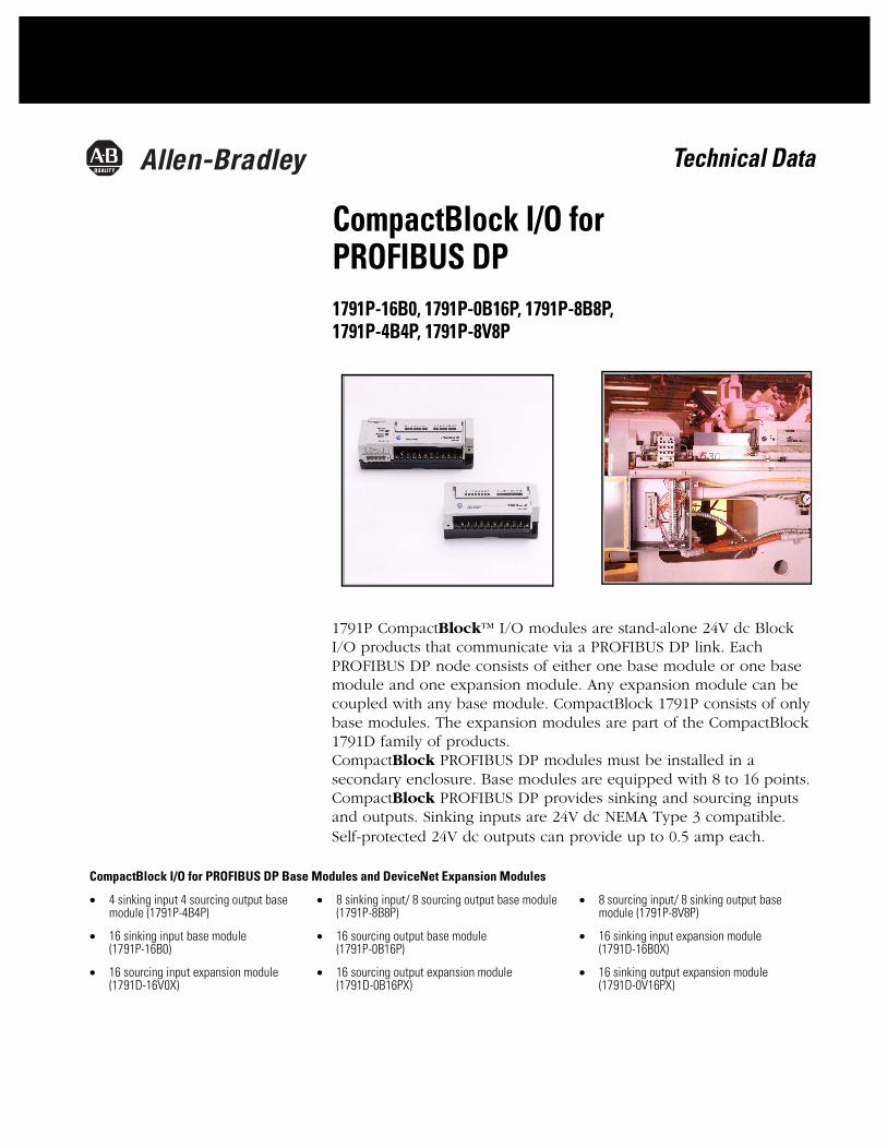
PROFIBUS DP Terminal Connector
The terminal connector on the CompactBlock PROFIBUS module uses a female 9-pin D-sub connector as shown below.
Pin numbers, names and descriptions for the connector are listed in the table below.
Network Status Indicator
Indication: Status:
Off Network offline
Yellow Network online
I/O Status Indicators
Function Indicator Module Illumination Condition
Outputs Each output: Yellow
NoneYellow
Output not energizedOutput energized
Inputs Each Input: Yellow
NoneYellow
No valid inputValid input
CompactBlock I/O 1791P-8V8P
8 INPUTS / 8 OUTPUTS . DC POWER
Status
Allen-Bradley
NetworkProfibus DP
01
23
45
67
01
23
45
67
Profibus DP
ModuleStatus
31337-m
Pin Number: Name: Description:
1 shield Shield, Protective Ground
2 M24V Minus 24V Output Voltage (Not used)
3 RxD/TxD-P Receive/Transmit-Data-P
4 CNTR-P Control-p
5 DGND Data Ground
6 VP Voltage-Plus
7 P24V Plus 24V Output Voltage (Not used)
8 RxD/TxD-N Receive/Transmit-Data-N
9 CNTR-N Control-N (Not used)
Publication 1791P-TD001B-EP - October 2002
CompactBlock I/O for PROFIBUS DP Overview 9
Base Module to Expansion Interface
The base module is linked to the expansion module with an 8-bit parallel bus, control lines, Vcc and ground connections, a reset/initialization line, and an expansion presence line. The 8-bit bus is multiplexed so that 16 bits of data (1 for each I/O point) can be transmitted/received with two transfers. The reset/initialization line is used during initialization of the module. The presence line is used for the detection of an expansion module at power up and for a period of each data transfer. Module ID is read over this bus at power up.1791P modules supply expansion power via expansion bus as follows:
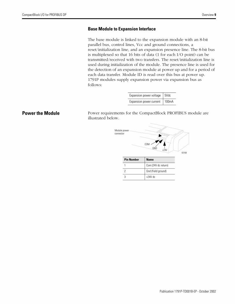
Power the Module Power requirements for the CompactBlock PROFIBUS module are illustrated below.
Expansion power voltage 5Vdc
Expansion power current 100mA
Module power connector
43108
Pin Number Name
1 Com (24V dc return)
2 Gnd (Field ground)
3 +24V dc
COMGND
+24V
Publication 1791P-TD001B-EP - October 2002

10 Overview CompactBlock I/O for PROFIBUS DP
Removable Terminal Block The CompactBlock PROFIBUS module contains a removable terminal block as shown below.
Mount the Module(s) Most base and expansion modules mount to a panel or DIN rail. The panel or DIN rail must be grounded before installing the module(s).
Base Module Mounting
You can install the CompactBlock base module on a panel or DIN rail, as illustrated to the left.
VDC
VDC
GND
GNDNotUsed
IN0IN2
IN4IN6
IN7IN5
IN3IN1
IN8IN10 IN12 IN14
IN15
IN13
IN11
IN9
Status
NetworkProfibus DP
01
23
45
67
01
23
45
67
ModuleStatus
Profibus DP
Retaining Screw
Retaining Screw
43111
StatusNetwork
0 1 2 3 4 5 6 7 0 1 2 3 4 5 6 7
CompactBlock I/OAllen-Bradley
Module
Status
Panel mount - front view
DIN rail mount- side view
Use a standard screwdriverto pull down the locking tab,then push the module ontothe DIN rail.
IMPORTANT Currently, these expansion blocks must be DIN rail mounted to meet our specifications:
• 1791D-16B0X• 1791D-16V0X• 1791D-0B16PX• 1791D-0V16PX
These expansion blocks cannot be panel mounted.
Publication 1791P-TD001B-EP - October 2002

CompactBlock I/O for PROFIBUS DP Overview 11
Expansion Module to Base Module Connection
The base module connects to the expansion module as illustrated below.
Profibus DP
NetworkStatus
0 1 2 3 4 5 6 7 0 1 2 3 4 5 6 7
CompactBlock I/O1791P-8V8P
8 INPUTS / 8 OUTPUTS - DC POWER
Allen-Bradley
Module
Status
Base Module Expansion Module
141 mm 5.55 in
41 mm 1.6 in
104 mm 4.09 in
41 mm 1.6 in
25 mm1 in
Expansion covers 43116
StatusNetwork
Profibus DP
Module
Status
0 1 2 3 4 5 6 7
CompactBlock I/O1791P-8V8P
8 INPUTS / 8 OUTPUTS - DC POWER
Allen-Bradley
0 1 2 3 4 5 6 7
Red strip must be on top of ribbon cable
A longer ribbon cable, 1791D-15CMCBL, lets you have 1 cm to 7 cm of space between modules.
43117
Publication 1791P-TD001B-EP - October 2002

12 Overview CompactBlock I/O for PROFIBUS DP
Word/Bit Definitions
The following table lists the combination of input and output modules and the input and output bytes produced and consumed.
Detailed Module Information The remainder of this publication describes detailed information for each CompactBlock I/O PROFIBUS module, such as:
• schematic diagrams• connection wiring diagrams• specificationsRefer to the table below to find information about a specific module.
Related Publication For installation instructions for the CompactBlock PROFIBUS module, refer to the Distributed I/O on PROFIBUS DP installation instructions, publication number, 1791P-IN001.
Base Expansion I/O Points Produced (input bytes)
Consumed (output bytes)
16 input 16 in 2 0
16 output 16 out 0 2
8 in / 8 out 8 in / 8 out 1 1
4 in / 4 out 4 in / 4 out 1 1
16 input 16 input 32 input 4 0
16 input 16 output 16 in / 16 out 2 2
16 output 16 input 16 in / 16 out 2 2
16 output 16 output 32 out 0 4
8 in / 8 out 16 input 24 in /8 out 3 1
8 in / 8 out 16 output 8 in / 24 out 1 3
4 in / 4 out 16 input 20 in / 4 out 3 1
4 in / 4 out 16 output 4 in / 20 out 1 3
For information about: See page:PROFIBUS DP Base and Expansion Terminal Modules
PROFIBUS Base and Expansion Modules General Specifications 13
24V DC, Sinking Input Base 1791P-16B0 and Expansion Modules 14
24V DC, 16 Sourcing Output Base 1791P-0B16P and Expansion Modules 15
24V DC, 8 Sinking Input Base/ 8 Sourcing Output 1791P-8B8P and Expansion Modules 16
24V DC, 4 Sinking Input Base/ 4 Sourcing Output 1791P-4B4P and Expansion Modules 17
24V DC, 8 Sourcing Input Base/ 8 Sinking Output 1791P-8V8P and Expansion Modules 18
16 sinking input expansion module (1791D-16B0X) 19
16 sourcing input expansion module (1791D-16V0X) 20
16 sourcing output expansion module (1791D-0B16PX) 21
16 sourcing output expansion module (1791D-0V16PX) 22
Publication 1791P-TD001B-EP - October 2002

CompactBlock Distributed I/O on PROFIBUS DP PROFIBUS Base and Expansion Modules 13
PROFIBUS Base and Expansion ModulesGeneral SpecificationsThe following table contains specifications that are common to all of the PROFIBUS base and expansion modules in this section. Individual module connection sizes, word/bit definitions, schematics, wiring diagrams and specifications are detailed after this table.
PROFIBUS DP Specifications
Network Protocol PROFIBUS-DP (EN50170)•Communication of the slave with a Class 1 master•Communication of the slave with a Class 2 master
Redundancy Not supported
Repeater Control Signal RS485 signal
Implementation Type DPC31
Freeze Mode Supported
Sync Mode Supported
Auto Baud Rate Supported
Fail Safe Mode Supported1
Station Type Slave
FMS Support Not supported
Number of nodes 125 maximum
Network Length/Communication rate
9.6KBPS @ 1000m (3280ft)19.2KBPS @ 1000m (3280ft)45.45KBPS @ 1000m (3280ft)93.75KBPS @ 1000m (3280ft)187.5KBPS @ 1000m (3280ft)500KBPS @ 400m (1312ft)3MBPS @ 100m (328ft)6MBPS @ 100m (328ft)12MBPS @ 100m (328ft)
General Specifications
Indicators Module status - red/green/orangeNetwork status - yellowI/O status - yellow
IsolationAuxiliary I/O power to PROFIBUSI/O group-to-groupI/O group-to-PROFIBUS
Type tested to 500V ac for 60 seconds
Type tested to 500V ac for 60 secondsType tested to 500V ac for 60 seconds
PROFIBUS DP Power VoltageCurrent
18 - 26.4V dc250mA maximum (with expansion)
Expansion Power VoltageCurrent
5V dc100mA
Auxiliary Power InputsVoltageCurrent
10-30V dc88mA each group of 8
Auxiliary Power OutputsVoltageCurrent
10-30V dc4A each group of 8
Base Module Dimensions 150mm X 50mm X 38mm5.91in X 1.97in X 1.5in
Expansion Module Dimensions
115mm X 50mm X 38mm4.4in X 1.97in X 1.5in
Operating Temperature IEC 60068-2-1 (Test Ad, Operating Cold),IEC 60068-2-2 (Test Bd, Operating Dry Heat),IEC 60068-2-14 (Test Nb, Operating Thermal Shock):0 to 60°C (32 to 140°F)
General Specifications (continued)
Field Wiring Tightening Torque 5-7lb-in. (0.5-0.6 Nm)
Storage Temperature IEC 60068-2-1 (Test Ab, Un-packaged Non-operating Cold),IEC 60068-2-2 (Test Bb, Un-packaged Non-operating Dry Heat),IEC 60068-2-14 (Test Na, Un-packaged Non-operating Thermal Shock):–40 to 85°C (–40 to 185°F)
Relative Humidity IEC 60068-2-30 (Test Db, Un-packaged Non-operating Damp Heat):5-95% non-condensing
Shock IEC60068-2-27 (Test Ea, Unpackaged Shock):Operating 30gNon-operating 50g
Vibration IEC60068-2-6 (Test Fc, Operating):5g @ 10-500Hz
Conductors Wire Size
Category
14 gauge (2mm2) stranded maximum3/64 inch insulation maximum22, 3
ESD Immunity IEC 61000-4-2:6kV contact discharge8kV air discharge
Radiated RF Immunity IEC 61000-4-3:10V/m with 1kHz sine-wave 80%AM from 80MHz to 1000MHz10V/m with 200Hz 50% Pulse 100%AM at 900Mhz
EFT/B Immunity IEC 61000-4-4:±2kV at 5kHz on signal ports±2kV at 5kHz on communications ports
Surge Transient Immunity IEC 61000-4-5:±1kV line-line(DM) and ±2kV line-earth(CM) on signal ports±2kV line-earth(CM) on shielded ports
Conducted RF Immunity IEC 61000-4-6:10Vrms with 1kHz sine-wave 80%AM from 150kHz to 80MHz
Emissions CSPR 11:Group 1, Class A
Enclosure Meets IP20
Certifications:(when product is marked)
c-UL-us UL Listed Industrial Control Equipment, certified for US and Canadac-UL-us UL Listed for Class I, Division 2 Group A,B,C,D Hazardous Locations, certified for U.S. and CanadaCE4 European Union 89/336/EEC EMC Directive, compliant with:
EN 50081-2; Industrial EmissionsEN 50082-2; Industrial ImmunityEN 61326; Meas./Control/Lab., Industrial Requirements61000-6-2; Industrial Immunity
C-Tick4 Australian Radiocommunications Act, compliant with:
AS/NZS 2064; Industrial Emissions
1. Dependant upon the scanner module being used. For example, the SST Scanner (cat. no. SST-PFB-SLC) does not fully support Fail Safe Mode, as it only resets outputs to 0. You cannot define behavior such as Hold Last State or Fault Value with the SST scanner.
2. You use this conductor category information for planning conductor routing as described in the system level installation manual.
3. See pub. 1770-4.1, Programmable Controller Wiring and Grounding Guidelines4. See the Product Certification link at www.ab.com for Declarations of Conformity,
Certificates, and other certification details.
Publication 1791P-TD001B-EN-P - October 2002

14 PROFIBUS Base and Expansion Modules CompactBlock Distributed I/O on PROFIBUS DP
24V DC 16 Sinking Input Base 1791P-16B0 and Expansion Modules
Wiring Diagram for 1791P-16B0 and 1791D-16BOX
1791P-16B0 Images Specifications
+
_
Input
24V dc
GND
System Circuitry
OptoIsolation
Input Indication LED (Logic)
42501
Simplified Schematic
1791P-16B0 Input Image
ByteBit Position
7 6 5 4 3 2 1 0
0 I7 I6 I5 I4 I3 I2 I1 I0
1 I15 I14 I13 I12 I11 I10 I9 I8
1791P-16B0 and 1791D-0B16PX or -OV16PX Input Image
ByteBit Position
7 6 5 4 3 2 1 0
0 I7 I6 I5 I4 I3 I2 I1 I0
1 I15 I14 I13 I12 I11 I10 I9 I8
1791P-16B0 and 1791D-0B16PX or -OV16PX Output Image
ByteBit Position
7 6 5 4 3 2 1 0
0 O7 O6 O5 O4 O3 O2 O1 O0
1 O15 O14 O13 O12 O11 O10 O9 O8
GND
IN 0 IN 2
+
IN 8IN 6
IN 1 IN 3
IN 4
IN 5 IN 7
IN 10
IN 9
IN 12 IN 14
IN 11 IN 15IN 13GND
-
VDC VDCNot Used
41671
1791P-16B0 and 1791D-16B0X or -16V0X Input Image
ByteBit Position
7 6 5 4 3 2 1 0
0 I7 I6 I5 I4 I3 I2 I1 I0
1 I15 I14 I13 I12 I11 I10 I9 I8
2 I23 I22 I21 I20 I19 I18 I17 I16
3 I31 I30 I29 I28 I27 I26 I25 I24
Sinking Input Specifications
Inputs per block groups of 4 or 8
Off-state Voltage 5V dc maximum
On-state Voltage 30V dc @ 40°C maximum25V dc @ 60°C maximum10V dc minimum
Off-state Current 1.5mA minimum
On-state Current 11mA @ 30V dc maximum2mA @ 10V dc minimum
Publication 1791P-TD001B-EN-P - October 2002
CompactBlock Distributed I/O on PROFIBUS DP PROFIBUS Base and Expansion Modules 15
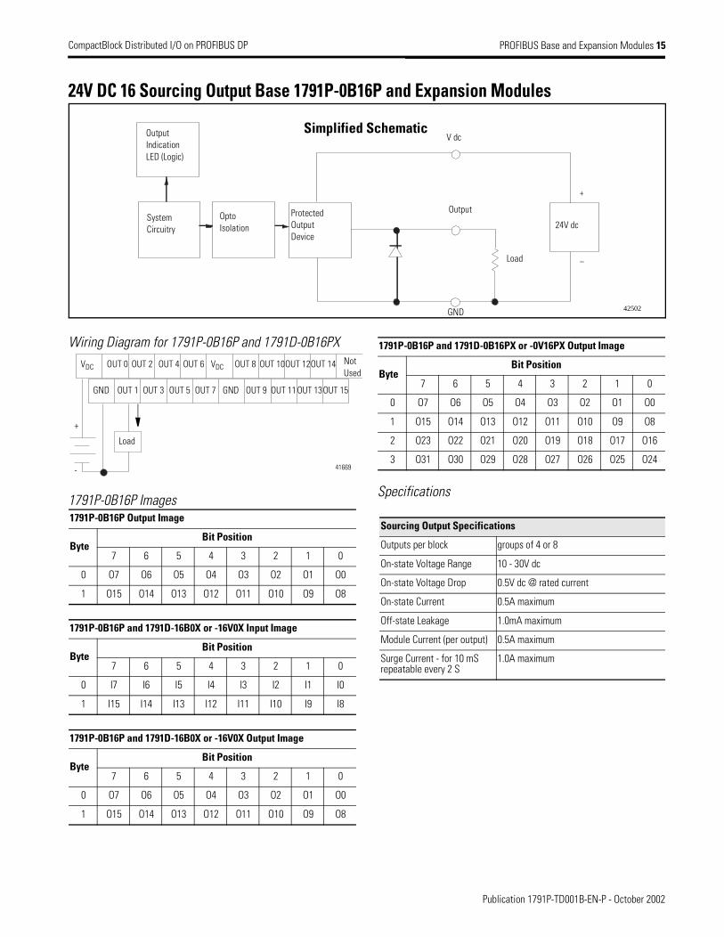
24V DC 16 Sourcing Output Base 1791P-0B16P and Expansion Modules
Wiring Diagram for 1791P-0B16P and 1791D-0B16PX
1791P-0B16P ImagesSpecifications
+
–
42502
Load
24V dc
GND
System Circuitry
OptoIsolation
Output Indication LED (Logic)
Output
V dc
Protected OutputDevice
Simplified Schematic
1791P-0B16P Output Image
ByteBit Position
7 6 5 4 3 2 1 0
0 O7 O6 O5 O4 O3 O2 O1 O0
1 O15 O14 O13 O12 O11 O10 O9 O8
1791P-0B16P and 1791D-16B0X or -16V0X Input Image
ByteBit Position
7 6 5 4 3 2 1 0
0 I7 I6 I5 I4 I3 I2 I1 I0
1 I15 I14 I13 I12 I11 I10 I9 I8
1791P-0B16P and 1791D-16B0X or -16V0X Output Image
ByteBit Position
7 6 5 4 3 2 1 0
0 O7 O6 O5 O4 O3 O2 O1 O0
1 O15 O14 O13 O12 O11 O10 O9 O8
VDC
GND
OUT 0 OUT 2
+
OUT 8OUT 6
OUT 1 OUT 3
OUT 4
OUT 5 OUT 7
OUT 10
OUT 9
OUT 12OUT 14
OUT 11 OUT 15OUT 13
VDC
GND
-
Load
Not Used
41669
1791P-0B16P and 1791D-0B16PX or -0V16PX Output Image
ByteBit Position
7 6 5 4 3 2 1 0
0 O7 O6 O5 O4 O3 O2 O1 O0
1 O15 O14 O13 O12 O11 O10 O9 O8
2 O23 O22 O21 O20 O19 O18 O17 O16
3 O31 O30 O29 O28 O27 O26 O25 O24
Sourcing Output Specifications
Outputs per block groups of 4 or 8
On-state Voltage Range 10 - 30V dc
On-state Voltage Drop 0.5V dc @ rated current
On-state Current 0.5A maximum
Off-state Leakage 1.0mA maximum
Module Current (per output) 0.5A maximum
Surge Current - for 10 mSrepeatable every 2 S
1.0A maximum
Publication 1791P-TD001B-EN-P - October 2002

16 PROFIBUS Base and Expansion Modules CompactBlock Distributed I/O on PROFIBUS DP
24V DC 8 Sinking Input /8 Sourcing Output Base - 1791P-8B8P and Expansion Modules
Wiring Diagram for 1791P-8B8P
1791P-8B8P Images
Specifications
+
_
+
–
Input Simplified Schematic
42500
Load24V dc
System Circuitry
OptoIsolation
Output Indication LED (Logic)
Input
V dc
Protected OutputDevice
OptoIsolation
System Circuitry 24V dc
Output
V dc
Gnd
Output Simplified Schematic
Input Indication LED (Logic)
1791P-8B8P Input Image
ByteBit Position
7 6 5 4 3 2 1 0
0 I7 I6 I5 I4 I3 I2 I1 I0
1791P-8B8POutput Image
ByteBit Position
7 6 5 4 3 2 1 0
0 O7 O6 O5 O4 O3 O2 O1 O0
1791P-8B8P and 1791D-16B0X or -16V0X Input Image
ByteBit Position
7 6 5 4 3 2 1 0
0 I7 I6 I5 I4 I3 I2 I1 I0
1 I15 I14 I13 I12 I11 I10 I9 I8
2 I23 I22 I21 I20 I19 I18 I17 I16
1791P-8B8Pand 1791D-16B0X or -16V0X Output Image
ByteBit Position
7 6 5 4 3 2 1 0
0 O7 O6 O5 O4 O3 O2 O1 O0
VDC
GND
IN 0 IN 2
+
OUT 0IN 6
IN 1 IN 3
IN 4
IN 5 IN 7
OUT 2
OUT 1
OUT 4 OUT 6
OUT 7OUT 5
VDC
GND
-+
-Load
Not Used
OUT 3
41672
1791P-8B8P and 1791D-OB16PX or -OV16PX Input Image
ByteBit Position
7 6 5 4 3 2 1 0
0 I7 I6 I5 I4 I3 I2 I1 I0
1791P-8B8P and 1791D-0B16PX or -0V16PX Output Image
ByteBit Position
7 6 5 4 3 2 1 0
0 O7 O6 O5 O4 O3 O2 O1 O0
1 O15 O14 O13 O12 O11 O10 O9 O8
2 O23 O22 O21 O20 O19 O18 O17 O16
Sinking Input Specifications
Inputs per block groups of 4 or 8
Off-state Voltage 5V dc maximum
On-state Voltage 30V dc @ 40°C maximum25V dc @ 60°C maximum10V dc minimum
Off-state Current 1.5mA minimum
On-state Current 11mA @ 30V dc maximum2mA @ 10V dc minimum
Sourcing Output Specifications
Outputs per block groups of 4 or 8
On-state Voltage Range 10 - 30V dc
On-state Voltage Drop 0.5V dc @ rated current
On-state Current 0.5A maximum
Off-state Leakage 1.0mA maximum
Module Current (per output)
0.5A maximum
Surge Current - for 10 mSrepeatable every 2 S
1.0A maximum
Publication 1791P-TD001B-EN-P - October 2002
CompactBlock Distributed I/O on PROFIBUS DP PROFIBUS Base and Expansion Modules 17
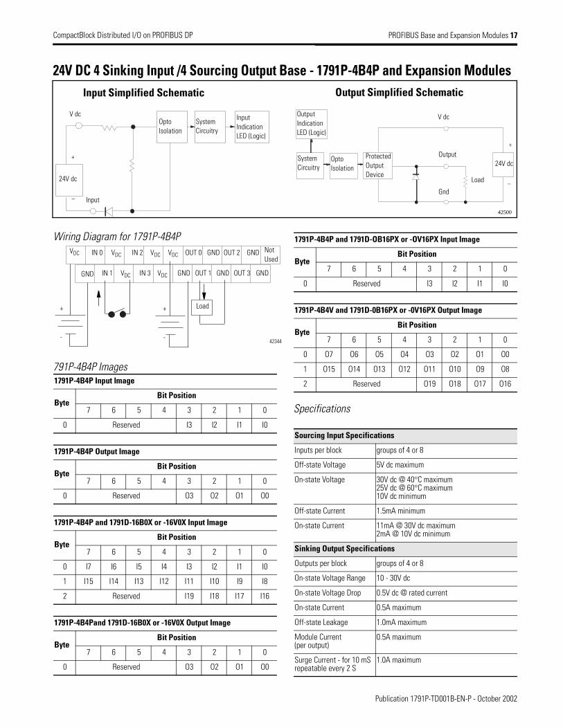
24V DC 4 Sinking Input /4 Sourcing Output Base - 1791P-4B4P and Expansion Modules
Wiring Diagram for 1791P-4B4P
791P-4B4P Images
Specifications
+
_
+
–
Input Simplified Schematic
42500
Load24V dc
System Circuitry
OptoIsolation
Output Indication LED (Logic)
Input
V dc
Protected OutputDevice
OptoIsolation
System Circuitry 24V dc
Output
V dc
Gnd
Output Simplified Schematic
Input Indication LED (Logic)
1791P-4B4P Input Image
ByteBit Position
7 6 5 4 3 2 1 0
0 Reserved I3 I2 I1 I0
1791P-4B4P Output Image
ByteBit Position
7 6 5 4 3 2 1 0
0 Reserved O3 O2 O1 O0
1791P-4B4P and 1791D-16B0X or -16V0X Input Image
ByteBit Position
7 6 5 4 3 2 1 0
0 I7 I6 I5 I4 I3 I2 I1 I0
1 I15 I14 I13 I12 I11 I10 I9 I8
2 Reserved I19 I18 I17 I16
1791P-4B4Pand 1791D-16B0X or -16V0X Output Image
ByteBit Position
7 6 5 4 3 2 1 0
0 Reserved O3 O2 O1 O0
IN 0 VDC OUT 0VDC
IN 1 VDC
IN 2
IN 3 VDC
GND
OUT 1
OUT 2 GND
GND GNDOUT 3
VDC VDC
GND GND
Not Used
Load+
-
+
-42344
1791P-4B4P and 1791D-OB16PX or -OV16PX Input Image
ByteBit Position
7 6 5 4 3 2 1 0
0 Reserved I3 I2 I1 I0
1791P-4B4V and 1791D-0B16PX or -0V16PX Output Image
ByteBit Position
7 6 5 4 3 2 1 0
0 O7 O6 O5 O4 O3 O2 O1 O0
1 O15 O14 O13 O12 O11 O10 O9 O8
2 Reserved O19 O18 O17 O16
Sourcing Input Specifications
Inputs per block groups of 4 or 8
Off-state Voltage 5V dc maximum
On-state Voltage 30V dc @ 40°C maximum25V dc @ 60°C maximum10V dc minimum
Off-state Current 1.5mA minimum
On-state Current 11mA @ 30V dc maximum2mA @ 10V dc minimum
Sinking Output Specifications
Outputs per block groups of 4 or 8
On-state Voltage Range 10 - 30V dc
On-state Voltage Drop 0.5V dc @ rated current
On-state Current 0.5A maximum
Off-state Leakage 1.0mA maximum
Module Current (per output)
0.5A maximum
Surge Current - for 10 mSrepeatable every 2 S
1.0A maximum
Publication 1791P-TD001B-EN-P - October 2002

18 PROFIBUS Base and Expansion Modules CompactBlock Distributed I/O on PROFIBUS DP
24V DC 8 Sourcing Input /8 Sinking Output Base - 1791P-8V8P and Expansion Modules
Wiring Diagram for 1791P-8V8P
1791P-8V8P Images
Specifications
+
_
+
–
Output Simplified Schematic
Output24V dc
Load
Opto Isolation
System Circuitry
Output Indication LED (Logic)
V dc
Protected Output Device
Gnd
Input Simplified Schematic
Input
24V dc
Opto Isolation
System Circuitry
Input Indication LED (Logic)
V dc
42500
1791P-8V8P Input Image
ByteBit Position
7 6 5 4 3 2 1 0
0 I7 I6 I5 I4 I3 I2 I1 I0
1791P-8V8POutput Image
ByteBit Position
7 6 5 4 3 2 1 0
0 O7 O6 O5 O4 O3 O2 O1 O0
1791P-8V8P and 1791D-16B0X or -16V0X Input Image
ByteBit Position
7 6 5 4 3 2 1 0
0 I7 I6 I5 I4 I3 I2 I1 I0
1 I15 I14 I13 I12 I11 I10 I9 I8
2 I23 I22 I21 I20 I19 I18 I17 I16
1791P-8V8Pand 1791D-16B0X or -16V0X Output Image
ByteBit Position
7 6 5 4 3 2 1 0
0 O7 O6 O5 O4 O3 O2 O1 O0
IN 0 IN 2 OUT 0IN 6
IN 1 IN 3
IN 4
IN 5 IN 7
OUT 2
OUT 1
OUT 4 OUT 6
OUT 3 OUT 7OUT 5
VDC VDC
GND GND
Not Used
Load+
- +
-
42346
1791P-8V8P and 1791D-OB16PX or -OV16PX Input Image
ByteBit Position
7 6 5 4 3 2 1 0
0 I7 I6 I5 I4 I3 I2 I1 I0
1791P-8V8P and 1791D-0B16PX or -0V16PX Output Image
ByteBit Position
7 6 5 4 3 2 1 0
0 O7 O6 O5 O4 O3 O2 O1 O0
1 O15 O14 O13 O12 O11 O10 O9 O8
2 O23 O22 O21 O20 O19 O18 O17 O16
Sinking Input Specifications
Inputs per block groups of 4 or 8
Off-state Voltage 5V dc maximum
On-state Voltage 30V dc @ 40°C maximum25V dc @ 60°C maximum10V dc minimum
Off-state Current 1.5mA minimum
On-state Current 11mA @ 30V dc maximum2mA @ 10V dc minimum
Sourcing Output Specifications
Outputs per block groups of 4 or 8
On-state Voltage Range 10 - 30V dc
On-state Voltage Drop 0.5V dc @ rated current
On-state Current 0.5A maximum
Off-state Leakage 1.0mA maximum
Module Current (per output)
0.5A maximum
Surge Current - for 10 mSrepeatable every 2 S
1.0A maximum
Publication 1791P-TD001B-EN-P - October 2002

CompactBlock Distributed I/O on PROFIBUS DP PROFIBUS Base and Expansion Modules 19
16 Sinking Input Expansion Module 1791D-16B0X
The 1791D-16BOX CompactBlock expansion module I/O can be used with the 1791 Remote I/O modules.
Wiring Connections
Input Wiring Diagram for 1791D-16B0X Expansion Module
Specifications
+
_
Simplified Schematic
Input
24V dc
OptoIsolation
System Circuitry
Input Indication LED (Logic)
GND42501
GND
IN 0 IN 2 IN 8IN 6
IN 1 IN 3
IN 4
IN 5 IN 7
IN 10
IN 9
IN 12 IN 14
IN 11 IN 15IN 13GND
VDC VDCNot
Used
41671
Sinking Inputs Specifications
Inputs per Block 2 groups of 8
Off-state Voltage 5V dc
On-state Voltage 30V dc @ 40°C 24V dc @ 60°C 10V dc minimum
Off-state Current 1.5mA @ 5V dc
On-state Current 11mA @ 30V dc
Publication 1791P-TD001B-EN-P - October 2002

20 PROFIBUS Base and Expansion Modules CompactBlock Distributed I/O on PROFIBUS DP
16 Sourcing Input Expansion Module 1791D-16V0X
The 1791D-16VOX CompactBlock expansion module I/O can be used with the 1791 Remote I/O modules.
Wiring Connections
Input Wiring Diagram for 1791D-16V0X Expansion Module
Specifications
Simplified Schematic
Input
24V dc
+
_
OptoIsolation
System Circuitry
Input Indication LED (Logic)
V dc
41886
VDC
GND
IN 0 IN 2 IN 8IN 6
IN 1 IN 3
IN 4
IN 5 IN 7
IN 10
IN 9
IN 12 IN 14
IN 11 IN 15IN 13
VDC
GND
41670
Not Used
Sourcing Inputs Specifications
Inputs per Block 2 groups of 8
Off-state Voltage 5V dc
On-state Voltage 30V dc @ 40°C 24V dc @ 60°C 10V dc minimum
Off-state Current 1.5mA @ 5V dc
On-state Current 11mA @ 30V dc
Publication 1791P-TD001B-EN-P - October 2002

CompactBlock Distributed I/O on PROFIBUS DP PROFIBUS Base and Expansion Modules 21
16 Sourcing Output Expansion Module 1791D-0B16PX
The 1791D-0B16PX CompactBlock expansion module I/O can be used with the 1791 Remote I/O modules.
Wiring Connections
Output Wiring Diagram for 1791D-0B16PXExpansion Module
Specifications
+
–
Simplified Schematic
Output24V dc
Load
OptoIsolation
System Circuitry
Output Indication LED (Logic)
V dc
Protected Output Device
Gnd 42502
VDC
GND
OUT 0 OUT 2 OUT 8OUT 6
OUT 1 OUT 3
OUT 4
OUT 5 OUT 7
OUT 10
OUT 9
OUT 12 OUT 14
OUT 11 OUT 15OUT 13
VDC
GND
Load
Not Used
41669
+
_
Sourcing Outputs Specifications
Outputs per Block 2 groups of 8
On-state Voltage Range 10 - 30V dc
On-state Voltage Drop 0.5V dc @ rated current
On-state Current 0.5A maximum
Off-state Leakage 1.0mA maximum
Module Current (all outputs) 4.0A maximum
Surge Current - for 10ms, repeatable every 2 s
1.0A maximum
Publication 1791P-TD001B-EN-P - October 2002
22 PROFIBUS Base and Expansion Modules CompactBlock Distributed I/O on PROFIBUS DP
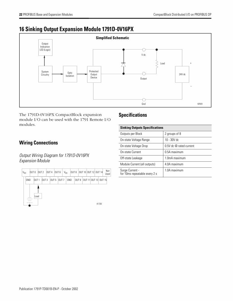
16 Sinking Output Expansion Module 1791D-0V16PX
The 1791D-0V16PX CompactBlock expansion module I/O can be used with the 1791 Remote I/O modules.
Wiring Connections
Output Wiring Diagram for 1791D-0V16PXExpansion Module
Specifications
+
_
Simplified Schematic
Output
24V dc
Load
OptoIsolation
System Circuitry
Output Indication LED (Logic)
V dc
Protected Output Device
Gnd 42503
VDC
GND
OUT 0 OUT 2 OUT 8OUT 6
OUT 1 OUT 3
OUT 4
OUT 5 OUT 7
OUT 10
OUT 9
OUT 12 OUT 14
OUT 11 OUT 15OUT 13
VDC
Load
GND
Not Used
41726
Sinking Outputs Specifications
Outputs per Block 2 groups of 8
On-state Voltage Range 10 - 30V dc
On-state Voltage Drop 0.5V dc @ rated current
On-state Current 0.5A maximum
Off-state Leakage 1.0mA maximum
Module Current (all outputs) 4.0A maximum
Surge Current - for 10ms repeatable every 2 s
1.0A maximum
Publication 1791P-TD001B-EN-P - October 2002


Publication 1791P-TD001B-EN-P - October 2002 2 PN 957707-92Supersedes Publication 1791P-TD001A-EN-P - June 2002 Copyright © 2002 Rockwell Automation, Inc. All rights reserved. Printed in the U.S.A
CompactBlock I/O, ControlLogix, PowerFlex, FlexArmor, FLEX I/O, and Point I/O are trademarks of Rockwell Automation, Inc.


![PROFIBUS DP bus interface, PROFIBUS DP [BU 2700]...Sicherheit/PROFIBUS DP [BU 2700]/Bestimmungsgemäße Ver wendung PROFIBUS DP @ 8\mod_1461835577600_388.docx @ 2249429 @ 2 @ 1 2.1](https://img.pdfslide.us/doc/110x75/60b54c574bd00c04b50e633d/profibus-dp-bus-interface-profibus-dp-bu-2700-sicherheitprofibus-dp-bu.jpg)