Embed Size (px)
Citation preview
RE 18306-02/11.2018, Bosch Rexroth AG
Compact power modulesKE, K and KS series
RE 18306-02Edition: 11.2018Replaces: 01.2017
ContentsOrdering Details 2General Technical Data 6Compact Power Module Type 9A.C. Electric Motors 10D.C. Electric Motors Standard Performance 16Central Manifold 32Built-in Valve 59Gear Pumps 74Oil Tanks 77Mounting position 88Modular Stackable Elements 90Accessories 116
Bosch Rexroth AG, RE 18306-02/11.2018
2 KE, K and KS series | Compact power modulesOrdering Details for Compact Power Modules with A.C. Motor
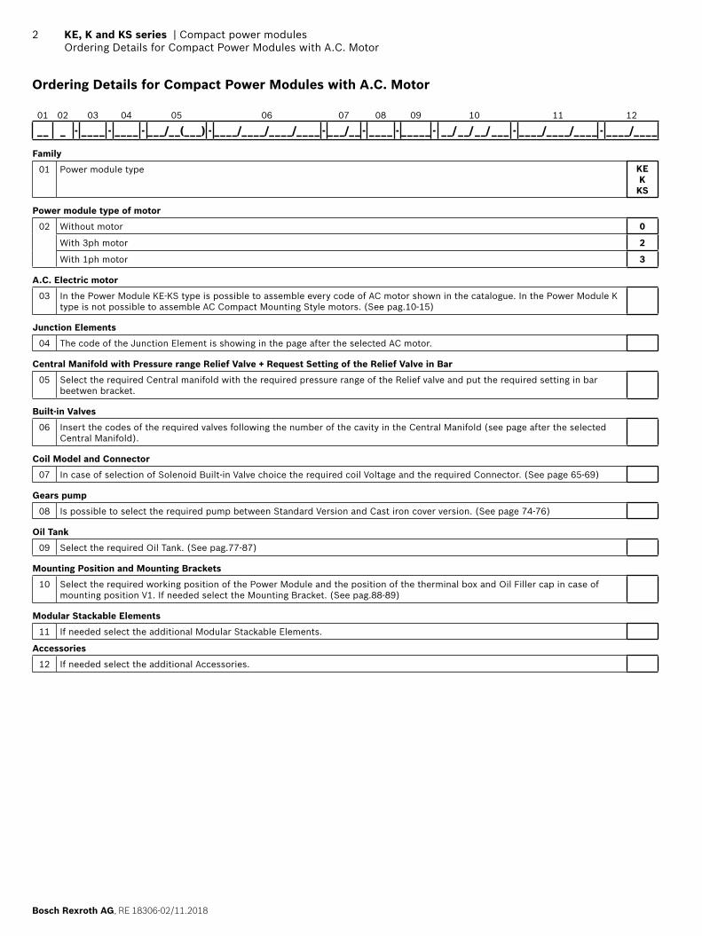
Ordering Details for Compact Power Modules with A.C. Motor
01 02 03 04 05 06 07 08 09 10 11 12
_ _ _ - _ _ _ _ - _ _ _ _ - _ _ _/_ _(_ _ _) - _ _ _ _/_ _ _ _/_ _ _ _/_ _ _ _ - _ _ _/_ _ - _ _ _ _ - _ _ _ _ _ - _ _/ _ _/ _ _/ _ _ _ - _ _ _ _/_ _ _ _/_ _ _ _ - _ _ _ _/_ _ _ _
Family
01 Power module type KEK
KS
Power module type of motor
02 Without motor 0
With 3ph motor 2
With 1ph motor 3
A.C. Electric motor
03 In the Power Module KE-KS type is possible to assemble every code of AC motor shown in the catalogue. In the Power Module K type is not possible to assemble AC Compact Mounting Style motors. (See pag.10-15)
Junction Elements
04 The code of the Junction Element is showing in the page after the selected AC motor.
Central Manifold with Pressure range Relief Valve + Request Setting of the Relief Valve in Bar
05 Select the required Central manifold with the required pressure range of the Relief valve and put the required setting in bar beetwen bracket.
Built-in Valves
06 Insert the codes of the required valves following the number of the cavity in the Central Manifold (see page after the selected Central Manifold).
Coil Model and Connector
07 In case of selection of Solenoid Built-in Valve choice the required coil Voltage and the required Connector. (See page 65-69)
Gears pump
08 Is possible to select the required pump between Standard Version and Cast iron cover version. (See page 74-76)
Oil Tank
09 Select the required Oil Tank. (See pag.77-87)
Mounting Position and Mounting Brackets
10 Select the required working position of the Power Module and the position of the therminal box and Oil Filler cap in case of mounting position V1. If needed select the Mounting Bracket. (See pag.88-89)
Modular Stackable Elements
11 If needed select the additional Modular Stackable Elements.
Accessories
12 If needed select the additional Accessories.
RE 18306-02/11.2018, Bosch Rexroth AG
Compact power modules | KE, K and KS series Ordering Details for Compact Power Modules with A.C. Motor
3
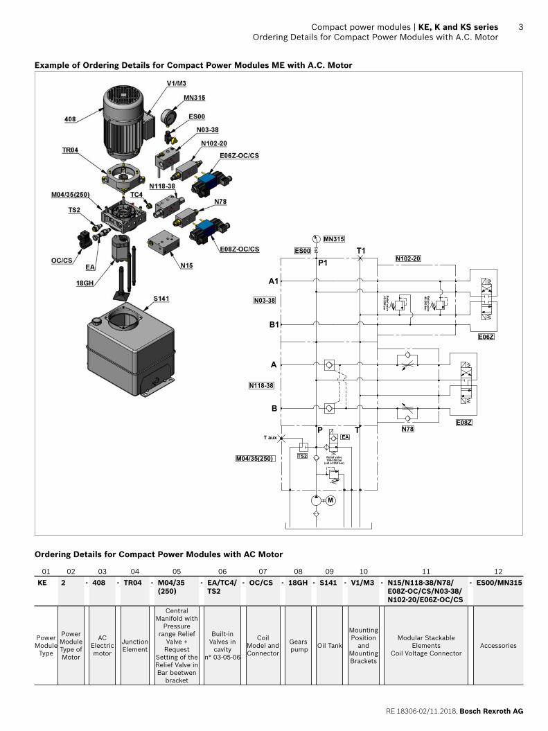
Example of Ordering Details for Compact Power Modules ME with A.C. Motor
T
B
P
A
E08ZN78
N118-38
Relief valve100-350 bar
(set at 250 bar)
EA
M
M04/35(250)
T aux
TS2
B1
P1
A1
N03-38
T1
MN315
ES00
E06Z
N102-20
Re
lief v
alv
e4
0-2
00
ba
r
Re
lief v
alv
e4
0-2
00
ba
r
Ordering Details for Compact Power Modules with AC Motor
01 02 03 04 05 06 07 08 09 10 11 12
KE 2 - 408 - TR04 - M04/35 (250)
- EA/TC4/TS2
- OC/CS - 18GH - S141 - V1/M3 - N15/N118-38/N78/E08Z-OC/CS/N03-38/N102-20/E06Z-OC/CS
- ES00/MN315
Power Module
Type
Power Module Type of Motor
AC Electric motor
Junction Element
Central Manifold with
Pressure range Relief
Valve + Request
Setting of the Relief Valve in Bar beetwen
bracket
Built-in Valves in
cavity n° 03-05-06
Coil Model and Connector
Gears pump Oil Tank
Mounting Position
and Mounting Brackets
Modular Stackable Elements
Coil Voltage ConnectorAccessories
Bosch Rexroth AG, RE 18306-02/11.2018
4 KE, K and KS series | Compact power modulesOrdering Details for Compact Power Modules ME with D.C. Motor
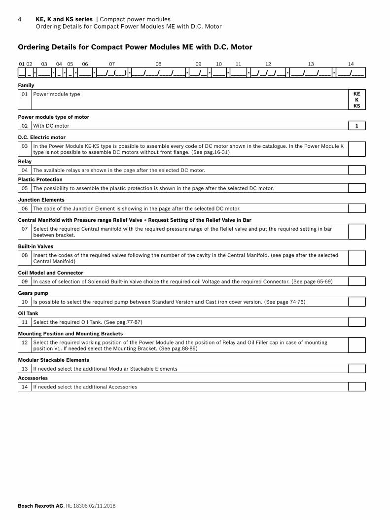
Ordering Details for Compact Power Modules ME with D.C. Motor
01 02 03 04 05 06 07 08 09 10 11 12 13 14
_ _ _ - _ _ _ _ - _ - _ - _ _ _ _ - _ _ _/_ _(_ _ _) - _ _ _ _/_ _ _ _/_ _ _ _/_ _ _ _ - _ _ _/_ _ - _ _ _ _ - _ _ _ _ _ - _ _/ _ _/ _ _/ _ _ _ - _ _ _ _/_ _ _ _/_ _ _ _ - _ _ _ _/_ _ _ _
Family
01 Power module type KEK
KS
Power module type of motor
02 With DC motor 1
D.C. Electric motor
03 In the Power Module KE-KS type is possible to assemble every code of DC motor shown in the catalogue. In the Power Module K type is not possible to assemble DC motors without front fl ange. (See pag.16-31)
Relay
04 The available relays are shown in the page after the selected DC motor.
Plastic Protection
05 The possibility to assemble the plastic protection is shown in the page after the selected DC motor.
Junction Elements
06 The code of the Junction Element is showing in the page after the selected DC motor.
Central Manifold with Pressure range Relief Valve + Request Setting of the Relief Valve in Bar
07 Select the required Central manifold with the required pressure range of the Relief valve and put the required setting in bar beetwen bracket.
Built-in Valves
08 Insert the codes of the required valves following the number of the cavity in the Central Manifold. (see page after the selected Central Manifold)
Coil Model and Connector
09 In case of selection of Solenoid Built-in Valve choice the required coil Voltage and the required Connector. (See page 65-69)
Gears pump
10 Is possible to select the required pump between Standard Version and Cast iron cover version. (See page 74-76)
Oil Tank
11 Select the required Oil Tank. (See pag.77-87)
Mounting Position and Mounting Brackets
12 Select the required working position of the Power Module and the position of Relay and Oil Filler cap in case of mounting position V1. If needed select the Mounting Bracket. (See pag.88-89)
Modular Stackable Elements
13 If needed select the additional Modular Stackable Elements
Accessories
14 If needed select the additional Accessories
RE 18306-02/11.2018, Bosch Rexroth AG
Compact power modules | KE, K and KS series Ordering Details for Compact Power Modules ME with D.C. Motor
5
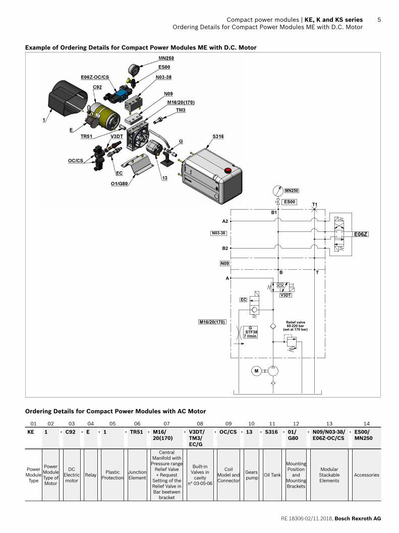
Example of Ordering Details for Compact Power Modules ME with D.C. Motor
Relief valve60-220 bar
(set at 170 bar)
V3DT
AB
M
EC
GSTF38
7 l/min
T
T1
A2
B2
B1
N09
N03-38
M16/20(170)
MN250
ES00
E06Z
Ordering Details for Compact Power Modules with AC Motor
01 02 03 04 05 06 07 08 09 10 11 12 13 14
KE 1 - C92 - E - 1 - TR51 - M16/ 20(170)
- V3DT/TM3/EC/G
- OC/CS - 13 - S316 - 01/G80
- N09/N03-38/E06Z-OC/CS
- ES00/MN250
Power Module
Type
Power Module Type of Motor
DC Electric motor
Relay Plastic Protection
Junction Element
Central Manifold with Pressure range
Relief Valve + Request
Setting of the Relief Valve in Bar beetwen
bracket
Built-in Valves in
cavity n° 03-05-06
Coil Model and Connector
Gears pump Oil Tank
Mounting Position
and Mounting Brackets
Modular Stackable Elements
Accessories
Bosch Rexroth AG, RE 18306-02/11.2018
6 KE, K and KS series | Compact power modulesGeneral Technical Data for Compact Power Module KE-K and KS series
General Technical Data for Compact Power Module KE-K and KS series
Through the years DCOC has developed a highly evolved modular system resulting in powerful, fl exible and cost effective power pack range, identifi ed as “compact power modules”. In its easier confi guration, a “compact power module” is an assembly of electric motor, central manifold with valves, pump, oil tank and a few connection elements. The central manifold, with its built-in valves, allows to achieve a large variety of hydraulic control circuits. If more complex circuits are needed, modular integrated blocks can be added by fl ange mounting, or interfacing, to the central manifold to extend its capabilities.
Typical applicationsPassenger liftFork liftCar and motorcycle liftLift tableDumperTail gateScissor liftGangway and davits for boatsMaterial handlingFoods machinery
Power module selectionChoose the circuit which meets your application requirements.Take note of all dimensions resulting from the basic components chosen for your application.
Note dimensions may vary slightly and should be confi rmed by DCOC, if the assembly is to be installed in a space with narrow clearance.
The tank capacity and the tank dimensions need to be large enough to assure proper pump suction: there must always be a reserve of oil in the tank when all cylinders are fully extended and avoid overfl ow when cylinders are fully retracted.The tank must be evaluated also for best separation of air from oil, and for settling down oil contamination. It should be placed in a space with, at least, natural ventilation and it should permit enough heat dissipation to prevent high fl uid temperature.Select the electric motor by evaluating the power needed and the motor compliance with the heat developed during the expected run time (or “duty cycle”).
Hydraulic fl uid for compact power moduleMineral oil based hydraulic fl uids suitable for hydraulic systems can be used; they should have physical lubricating and chemical properties as specifi ed by: MINERAL OIL BASED HYDRAULIC FLUIDS HL
(DIN 51524 part 1) MINERAL OIL BASED HYDRAULIC FLUIDS HL P
(DIN 51524 part 2)For use of environmentally friendly fl uids please consult DCOC.
Fluid viscosity, temperature range of the operating fl uid, ambient temperatureThe fl uid viscosity should remain within the range 10 to 300 cSt (centistokes); recommended 15 to 120 cSt. Permissive cold start viscosity is maximum 2000 cSt.The fl uid temperature should remain within the range -15°C and 80°C (5°F and 176°F).
Note For compact power module with plastic tank the fl uid temperature should remain within the range -15°C and 70°C (5°F and 158°F). Ambient temperature -15°C +40°C (5°F and 104°F).
Fluid cleanliness requirements and maintenanceWe recommend a cleanliness of the operating fl uid according to ISO 4406 Class 20/18/15 or cleaner.All components of the hydraulic circuit , including hoses and actuators, must be fl ushed and cleaned before assembling, because the compact power module has a suction fi lter only.The hydraulic fl uid should be replaced after the fi rst 50 hours, and then every 1000 hours, or, at least, once a year.
Power module installationThe mounting position (is basically un-restricted; just avoid installations that could compromise the pump suction, it is recommended to support the power module on vibration dampening blocks when the mounting structure is expected to vibrate.
Wiring and starting-upThe wiring between battery and electric motor should be selected in order to avoid excessive voltage drop (recommended less than 1 V).It is strictly forbidden to allow the backwards rotation of the pump even at the fi rst starting: to prevent reverse
RE 18306-02/11.2018, Bosch Rexroth AG
Compact power modules | KE, K and KS series General Technical Data for Compact Power Module KE-K and KS series
7
rotation, the wiring polarities must be correctly connected (except for the reversible pumps).Caution: when energized, the surface temperature of the electric motor could reach temperature levels of 60-80°C (140-176°F): care should be taken to avoid any accidental contact of people with the motor surface.
A.C. motorsThe tolerances on the nominal voltage are:Single phase motor: 230V +/-5% - Three phase motor: 230-400V +/-10%.Protection degree : IP54 (protection against dust and water splash).Insulation class: F (155°C) (311°F).All motors are aluminum alloy die cast without painting.
Note Standard Single phase motors have a permanently connected run capacitor. If the motor starts with pressure in the circuit (load in the actuator) we suggest the use of specials dedicated manifolds KE series with integrated Start-Up valve (Manifold code M09 and M19).
D.C. MotorsDCOC has a wide range of D.C. motors. In the following pages you will fi nd a selection of our standard range. For further information about our complete range please contact our Sales department.All the motors shown have clockwise rotation suitable for driving our counter clockwise gear pumps.For each motor a diagram is shown that enables the customer to select the right pump displacement needed for the required fl ow and working pressure.To be sure of selecting the best electric motor for the application, also the duty cycle has to be verifi ed.Following are the defi nitions of the type of duty cycles:S2 = Short time duty cycle: indicate the number of minutes the motor can operate before reaching the maximum allowable temperature. After this time the motor must cool down until the ambient temperature is reached.S3 = Intermittent duty cycle: indicate the maximum time percentage (%) based on 10 minute period within the motor can run until reaching the maximum allowable temperature. For example an S3 value of 15% = 1,5 minutes running time every 10 minutes period. For 8,5 minutes the motor is switched-off. The S2 and S3 values are related to the current draw. On the label of motor are indicated the S2 and S3 values referred to the nominal power of the motor.To check the S2 or S3 value at different conditions is necessary to fi nd the value of current in the motor-pumps
diagram and related it with the represented list.All the diagrams motor-pumps are obtained at the nominal voltage of 12 or 24 Volt using fl uid ISO VG 46 at 20-30°C (68-86°F).
Central manifoldsAll the Central Manifolds shown in the catalogue are made in die cast aluminium alloy except the manifold code 10 for CPM MR series that is made by extruded bar. The validation of the Central Manifolds follows a life-test with 250 bar (625 psi) pulsed pressure repeated for 300.000 cycles.
Built-in valvesA wide range of cartridge valves and special plugs is available to be assembled in our Central Manifolds. The cartridge valves shown are designed for use in our Compact Power Module and are manufactured using steel with high mechanical strength. Surface treatments protect the exposed parts to the external environment. Standard seals are NBR (BUNA-N) with backup rings in PTFE. The cartridge valves with “leak proof seat design” have an average leakage of 10-15 drops/minute (< 1 cm3/minute 0.06 in3/min.) at the maximum pressure using fl uid ISO VG46 at 40°C (104°F). The validation of the cartridge valves follows a life-test at pulsed maximum pressure (indicated for each valve) repeated for 500.000 cycles. All the solenoid cartridge valves are fi tted with protective O-Rings installed between the pole tube and the coil. These O-Rings protect the internal parts from condensation and contaminants , which could cause malfunction.All the solenoid cartridge valves are designed for operating in D.C. Power supply in A.C. requires a connector with bridge rectifi er included.
External gear pumpsDCOC offers a wide range of External Gear Pumps to cover different kinds of applications. The standard versions are suitable for the biggest part of applications. For applications requiring higher peaks of pressure (for example Car Lift and Presses) a version with cast iron covers is available. For applications requiring high numbers of Start&Stop or low noise feature the tapered shaft version for elastic coupling is preferred (available only for central manifold K series with A.C. motors). All the pumps are pressure compensated to guarantee the best effi ciency.
Bosch Rexroth AG, RE 18306-02/11.2018
8 KE, K and KS series | Compact power modulesGeneral Technical Data for Compact Power Module KE-K and KS series
Oil tanks In this catalogue you will fi nd a wide selection of steel and plastic tanks available as a standard product. If a special tank is required please contact our Sales Department. Steel tanks have Black paint fi nish and are suitable for operating temperature range -15°C / +80°C (5°F / 176°F). Plastic tanks are obtained in one piece in order to avoid welded parts that are weak points at extreme temperature and vibrations. Plastic tanks are suitable for operating temperature range -15°C / +70°C (5°F / 158°F).
Note even if the plastic tank mounting system is designed to avoid oil leakage the tank must be securely anchored when fi tted in mobile equipment and when subject to shocks and heavy vibrations. Please check that the anchorages do not stress or deform the tank.
Modular stackable elementsOur modular system offers a wide range of standardised elements. They are divided in two main series:Modular Elements “N” series: Modular blocks for different mounting position with mechanical valve or interface for CETOP valves to create parallel or series circuits.Modular Elements “V” series: Modular blocks that incorporate solenoid operated cartridge valves 2,3,4 way.All the Modular Elements are made in extruded aluminum alloy. In the catalogue you will fi nd a selection of the main used models.
Note To reduce the complexity of the system and optimize the available space, special Modular Elements can be designed and manufactured following the customers needs. In this case please contact our Sales Department.
European machine directive 2006/42/CEAccording to the Machine Directive2006/42/CE, a complete power module, as described in paragraph 15 and made available to the European market, enters into the defi nition of “partly completed machinery”.Instead, the power module sub-assemblies (motor, pump, reservoir, central manifold,...), when not assembled into a complete power pack, are considered “components” which can be employed in a “machinery” or a “partly completed machinery”. In this case, the DCOC components and sub-assemblies must be fi tted in compliance with all the relevant technical data sheet applicable to the product, and shall not be operated, adjusted or disassembled before the complete machinery where they are incorporated has been
declared to be in compliance with the Machine Directive 2006/42/CE.
Note All the components shown in the catalogue ARE NOT suitable for use in potentially explosive atmosphere.
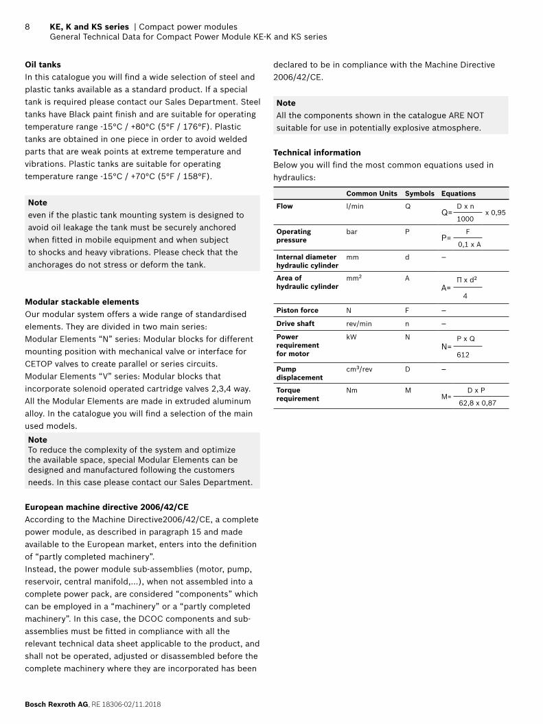
Technical informationBelow you will fi nd the most common equations used in hydraulics:
Common Units Symbols Equations
Flow l/min QQ=
D x nx 0,95
1000
Operating pressure
bar PP=
F
0,1 x A
Internal diameter hydraulic cylinder
mm d –
Area of hydraulic cylinder
mm2 AA=
Π x d2
4
Piston force N F –
Drive shaft rev/min n –
Power requirementfor motor
kW NN=
P x Q
612
Pump displacement
cm3/rev D –
Torquerequirement
Nm MM=
D x P
62,8 x 0,87

RE 18306-02/11.2018, Bosch Rexroth AG
Compact power modules | KE, K and KS series Compact Power Module Type
9
Compact Power Module Type
Standard Type KE series
Complex circuits, direct fl ange AC motors.DC motors up to 3000 W.AC motors up to 4000 W (5,5 hp).Pump displacement up to 7,9 cm3 (0,31 inch3).Pressure up to 300 bar (4350 psi).Optionals:Start-up valve inside.3-ways solenoid operated valve inside.4-ways solenoid operated valve inside.AC electric motor with direct coupling for smaller dimensions.Gear pumps with splined shaft.Low noise pumps.
Optional Type K series
Standardized central manifold for simple hydraulics circuits.DC motors up to 3000 W.AC motors up to 4000 W (5,5 hp).Pump displacement up to 7,9 cm3 (0,31 inch3).Pressure up to 300 bar (4350 psi).Optionals:Elastic coupling.
Optional Type KS series
Designed for lifting applications.Ready solution for simple acting circuits with the possibility of unloading valve.DC motors up to 3000 W.AC motors up to 4000 W (5,5 hp).Pump displacement up to 7,9 cm3 (0,31 inch3).Pressure up to 300 bar (4350 psi).
Note that every power module type can be mounted in horizontal or vertical position.
Bosch Rexroth AG, RE 18306-02/11.2018
10 KE, K and KS series | Compact power modulesA.C. Electric Motors Standard Flange
Dimensions [mm (inches)]
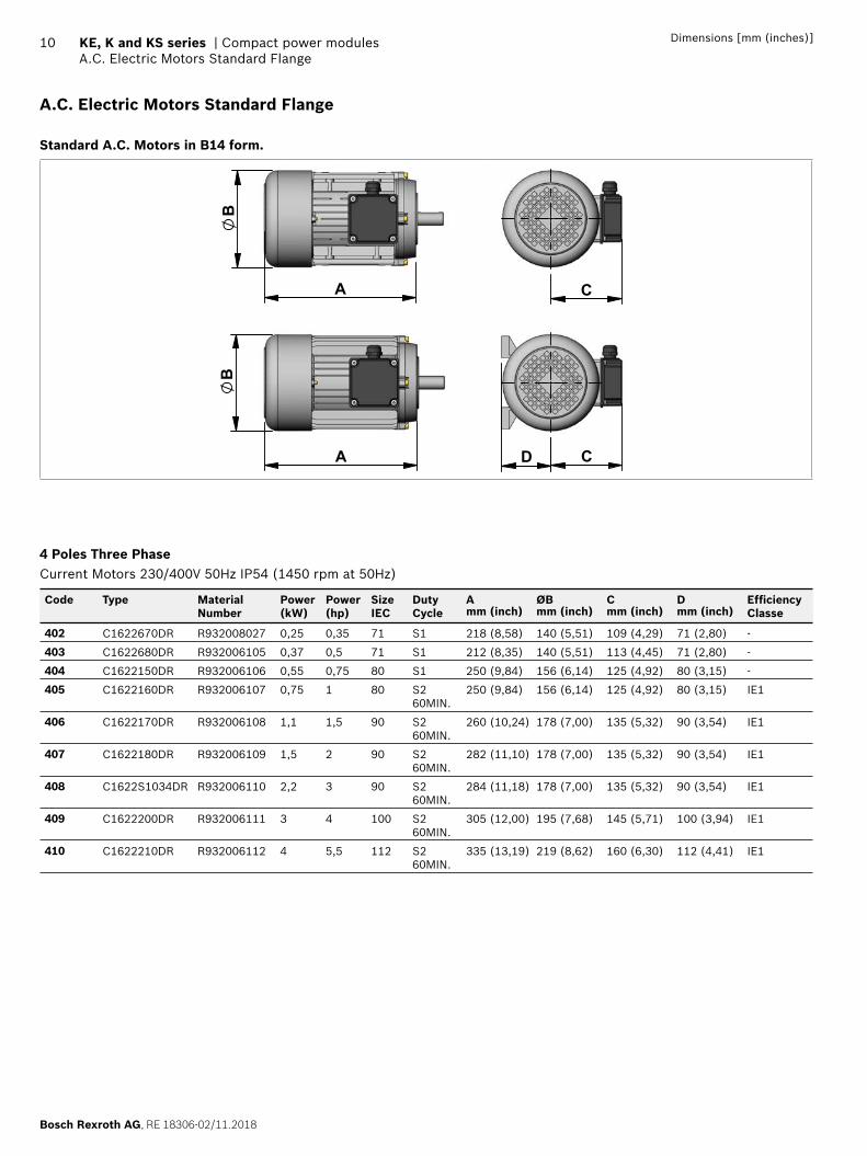
A.C. Electric Motors Standard Flange
Standard A.C. Motors in B14 form.
A
B
C
CDA
B
4 Poles Three PhaseCurrent Motors 230/400V 50Hz IP54 (1450 rpm at 50Hz)
Code Type Material Number
Power(kW)
Power(hp)
Size IEC
Duty Cycle
Amm (inch)
ØBmm (inch)
Cmm (inch)
Dmm (inch)
Effi ciency Classe
402 C1622670DR R932008027 0,25 0,35 71 S1 218 (8,58) 140 (5,51) 109 (4,29) 71 (2,80) -
403 C1622680DR R932006105 0,37 0,5 71 S1 212 (8,35) 140 (5,51) 113 (4,45) 71 (2,80) -
404 C1622150DR R932006106 0,55 0,75 80 S1 250 (9,84) 156 (6,14) 125 (4,92) 80 (3,15) -
405 C1622160DR R932006107 0,75 1 80 S2 60MIN.
250 (9,84) 156 (6,14) 125 (4,92) 80 (3,15) IE1
406 C1622170DR R932006108 1,1 1,5 90 S2 60MIN.
260 (10,24) 178 (7,00) 135 (5,32) 90 (3,54) IE1
407 C1622180DR R932006109 1,5 2 90 S2 60MIN.
282 (11,10) 178 (7,00) 135 (5,32) 90 (3,54) IE1
408 C1622S1034DR R932006110 2,2 3 90 S2 60MIN.
284 (11,18) 178 (7,00) 135 (5,32) 90 (3,54) IE1
409 C1622200DR R932006111 3 4 100 S2 60MIN.
305 (12,00) 195 (7,68) 145 (5,71) 100 (3,94) IE1
410 C1622210DR R932006112 4 5,5 112 S2 60MIN.
335 (13,19) 219 (8,62) 160 (6,30) 112 (4,41) IE1
RE 18306-02/11.2018, Bosch Rexroth AG
Compact power modules | KE, K and KS series A.C. Electric Motors Standard Flange
11Dimensions [mm (inches)]
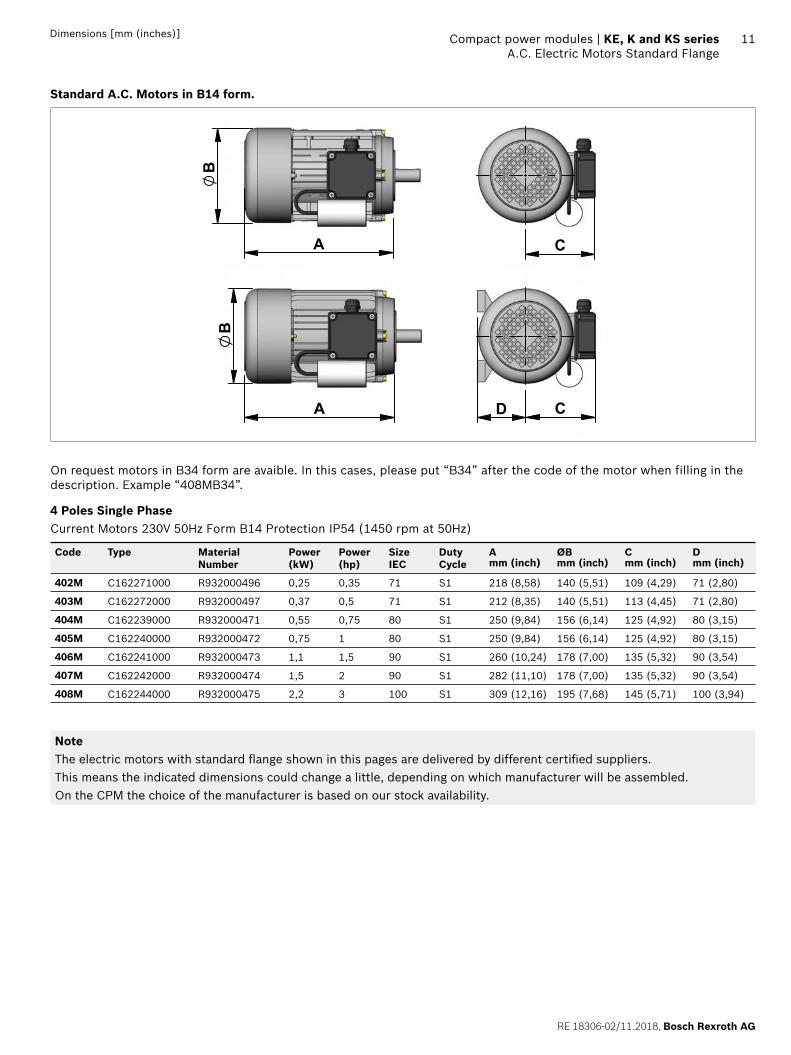
Standard A.C. Motors in B14 form.
A
B
C
CDA
B
On request motors in B34 form are avaible. In this cases, please put “B34” after the code of the motor when filling in the description. Example “408MB34”.
4 Poles Single PhaseCurrent Motors 230V 50Hz Form B14 Protection IP54 (1450 rpm at 50Hz)
Code Type Material Number
Power(kW)
Power(hp)
Size IEC
Duty Cycle
Amm (inch)
ØBmm (inch)
Cmm (inch)
Dmm (inch)
402M C162271000 R932000496 0,25 0,35 71 S1 218 (8,58) 140 (5,51) 109 (4,29) 71 (2,80)
403M C162272000 R932000497 0,37 0,5 71 S1 212 (8,35) 140 (5,51) 113 (4,45) 71 (2,80)
404M C162239000 R932000471 0,55 0,75 80 S1 250 (9,84) 156 (6,14) 125 (4,92) 80 (3,15)
405M C162240000 R932000472 0,75 1 80 S1 250 (9,84) 156 (6,14) 125 (4,92) 80 (3,15)
406M C162241000 R932000473 1,1 1,5 90 S1 260 (10,24) 178 (7,00) 135 (5,32) 90 (3,54)
407M C162242000 R932000474 1,5 2 90 S1 282 (11,10) 178 (7,00) 135 (5,32) 90 (3,54)
408M C162244000 R932000475 2,2 3 100 S1 309 (12,16) 195 (7,68) 145 (5,71) 100 (3,94)
NoteThe electric motors with standard fl ange shown in this pages are delivered by different certifi ed suppliers.This means the indicated dimensions could change a little, depending on which manufacturer will be assembled.On the CPM the choice of the manufacturer is based on our stock availability.
Bosch Rexroth AG, RE 18306-02/11.2018
12 KE, K and KS series | Compact power modulesJunction Elements for A.C. Electric Motor Standard Flange
Dimensions [mm (inches)]
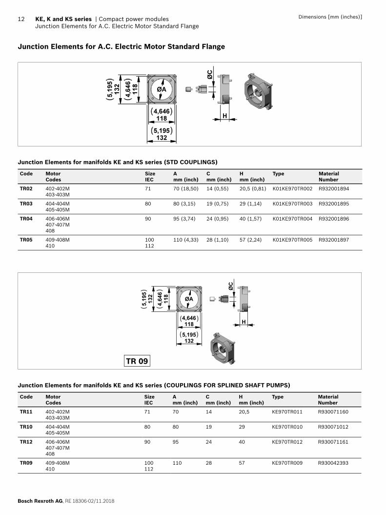
Junction Elements for A.C. Electric Motor Standard Flange
Junction Elements for manifolds KE and KS series (STD COUPLINGS)
Code Motor Codes
SizeIEC
Amm (inch)
Cmm (inch)
Hmm (inch)
Type Material Number
TR02 402-402M 403-403M
71 70 (18,50) 14 (0,55) 20,5 (0,81) K01KE970TR002 R932001894
TR03 404-404M405-405M
80 80 (3,15) 19 (0,75) 29 (1,14) K01KE970TR003 R932001895
TR04 406-406M 407-407M 408
90 95 (3,74) 24 (0,95) 40 (1,57) K01KE970TR004 R932001896
TR05 409-408M 410
100 112
110 (4,33) 28 (1,10) 57 (2,24) K01KE970TR005 R932001897
1184,646
1325,195
132
5,195
118
4,646
ØA
ØC
H
( )
( )
()
()
TR 09
Junction Elements for manifolds KE and KS series (COUPLINGS FOR SPLINED SHAFT PUMPS)
Code Motor Codes
SizeIEC
Amm (inch)
Cmm (inch)
Hmm (inch)
Type Material Number
TR11 402-402M403-403M
71 70 14 20,5 KE970TR011 R930071160
TR10 404-404M405-405M
80 80 19 29 KE970TR010 R930071012
TR12 406-406M407-407M408
90 95 24 40 KE970TR012 R930071161
TR09 409-408M410
100112
110 28 57 KE970TR009 R930042393
RE 18306-02/11.2018, Bosch Rexroth AG
Compact power modules | KE, K and KS series Junction Elements for A.C. Electric Motor Standard Flange
13Dimensions [mm (inches)]
B
A C
H
712,795
()
993,898
993,898
A
C71
2,795
12,50,492( )
( )
()
()
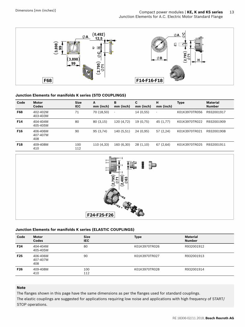
F68 F14-F16-F18
Junction Elements for manifolds K series (STD COUPLINGS)
Code Motor Codes
SizeIEC
Amm (inch)
Bmm (inch)
Cmm (inch)
Hmm (inch)
Type Material Number
F68 402-402M 403-403M
71 70 (18,50) - 14 (0,55) - K01K3970TR056 R932001917
F14 404-404M405-405M
80 80 (3,15) 120 (4,72) 19 (0,75) 45 (1,77) K01K3970TR022 R932001909
F16 406-406M 407-407M 408
90 95 (3,74) 140 (5,51) 24 (0,95) 57 (2,24) K01K3970TR021 R932001908
F18 409-408M 410
100 112
110 (4,33) 160 (6,30) 28 (1,10) 67 (2,64) K01K3970TR025 R932001911
712,795
632,480
()
()
F24-F25-F26
Junction Elements for manifolds K series (ELASTIC COUPLINGS)
Code Motor Codes
SizeIEC
Type Material Number
F24 404-404M405-405M
80 K01K3970TR026 R932001912
F25 406-406M407-407M408
90 K01K3970TR027 R932001913
F26 409-408M410
100112
K01K3970TR028 R932001914
NoteThe fl anges shown in this page have the same dimensions as per the fl anges used for standard couplings.The elastic couplings are suggested for applications requiring low noise and applications with high frequency of START/STOP operations.
Bosch Rexroth AG, RE 18306-02/11.2018
14 KE, K and KS series | Compact power modulesA.C. Electric Motor Compact Mounting Style for Power Module Type KE and KS
Dimensions [mm (inches)]
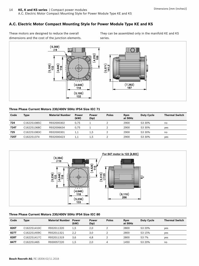
A.C. Electric Motor Compact Mounting Style for Power Module Type KE and KS
These motors are designed to reduce the overall dimensions and the cost of the junction elements.
They can be assembled only in the manifold KE and KS series.
108
4,252
1184,646
1325,195
118
4,646
132
5,195
90,369
1877,362
141,5
5,571
( )
( )
( )
( )
()
()
() (
)
Three Phase Current Motors 230/400V 50Hz IP54 Size IEC 71
Code Type Material Number Power(kW)
Power(hp)
Poles Rpm at 50Hz
Duty Cycle Thermal Switch
724 C1622S1085C R932000302 0,75 1 2 2900 S3 30% no
724T C1622S1368C R932006634 0,75 1 2 2900 S3 30% yes
725 C1622S1083C R932000301 1,1 1,5 2 2900 S3 30% no
725T C1622S1374 R932000423 1,1 1,5 2 2900 S3 30% yes
135
5,31
5
2068,110118
4,646
118
4,64
6
1335,236
133
5,23
6
115
4,52
8
100,394
For 847 motor is 122 4,803
( )
()(
)
()
()
( )( )
( )( )
Three Phase Current Motors 230/400V 50Hz IP54 Size IEC 80
Code Type Material Number Power(kW)
Power(hp)
Poles Rpm at 50Hz
Duty Cycle Thermal Switch
826T C1622S1410C R932011320 1,5 2,0 2 2800 S3 20% yes
827T C1622S1409C R932011321 2,2 3,0 2 2800 S3 15% yes
828T C1622S1417C R932011319 3,6 4,8 2 2800 S3 7% yes
847T C1622S1465 R930057220 1,5 2,0 4 1450 S3 20% no
RE 18306-02/11.2018, Bosch Rexroth AG
Compact power modules | KE, K and KS series Junction Elements for A.C. Electric Motor Compact Mounting Style for Power Module Type KE and KS
15Dimensions [mm (inches)]
NoteThe motors shown in these tables are a selection of our range. In case of needs of different technical characteristics PLEASE CONTACT OUR SALES DEPARTEMENT.The electric motors with compact mounting style shown in this pages are delivered by different certifi ed suppliers.This means the indicated dimensions could change a little, depending on which manufacturer will be assembled.On the CPM the choice of the manufacturer is based on our stock availability.
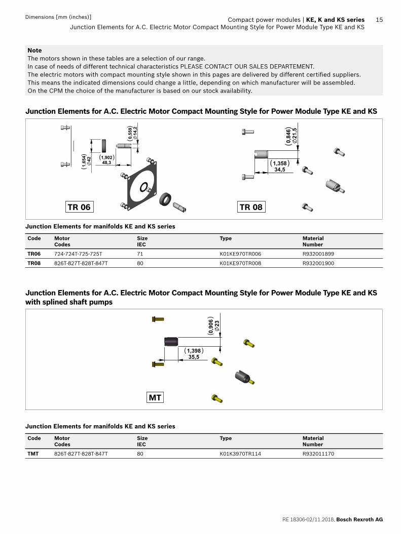
Junction Elements for A.C. Electric Motor Compact Mounting Style for Power Module Type KE and KS
421,654
48,31,902
14,2
0,559
( )
()
()
34,51,358
21,5
0,846
( )
()
TR 06 TR 08
Junction Elements for manifolds KE and KS series
Code Motor Codes
SizeIEC
Type Material Number
TR06 724-724T-725-725T 71 K01KE970TR006 R932001899
TR08 826T-827T-828T-847T 80 K01KE970TR008 R932001900
Junction Elements for A.C. Electric Motor Compact Mounting Style for Power Module Type KE and KS with splined shaft pumps
230,906
35,51,398( )
()
MT
Junction Elements for manifolds KE and KS series
Code Motor Codes
SizeIEC
Type Material Number
TMT 826T-827T-828T-847T 80 K01K3970TR114 R932011170
Bosch Rexroth AG, RE 18306-02/11.2018
16 KE, K and KS series | Compact power modulesD.C. Electric Motors Standard Performance
Dimensions [mm (inches)]
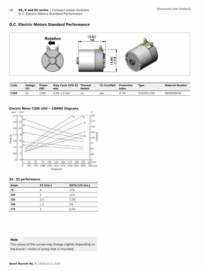
D.C. Electric Motors Standard Performance
114
4,49
1385,43Rotation ( )
()
Code Voltage(V)
Power(W)
Duty Cycle S3% S2 min.
Thermal Switch
UL Certifi ed Protection index
Type Material Number
C200 24 1200 4,5% 1,2 min no yes IP 54 C1620S1200 R930059616
Electric Motor C200 (24V – 1300W) Diagramsl/min
14
12
10
8
6
4
2
0
A
200
175
150
125
100
75
50
25
00 25 50 75 100 125 150 175 200 225 250 bar
0 363 725 1088 1450 1813 2175 2538 2901 3263 3626 psi
gpm
3,7
3,2
2,6
2,1
1,6
1,1
0,5
0
Flow
Q
CU
RR
EN
T
Pressure
S2 - S3 performance
Amps S2 (min.) S3(%) (10 min.)
75 6 17%
100 4 11%
125 2,4 7,5%
150 1,5 5%
175 1 3,5%
NoteThe values of the curves may change slightly depending on the brand / model of pump that is mounted.
RE 18306-02/11.2018, Bosch Rexroth AG
Compact power modules | KE, K and KS series Relay
17Dimensions [mm (inches)]
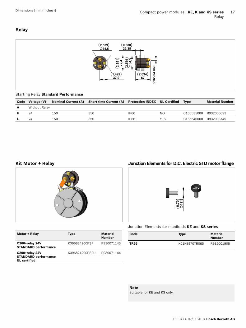
Relay
672,634
64,5
2,53
972
,42,
851
5/16
"-24
UN
F
22,350,880
64,52,539
37,91,492
( )
( )
( )
( )
()
()
Starting Relay Standard Performance
Code Voltage (V) Nominal Current (A) Short time Current (A) Protection INDEX UL Certifi ed Type Material Number
A Without Relay
H 24 150 350 IP66 NO C165535000 R932000693
L 24 150 350 IP66 YES C165540000 R932008749
Kit Motor + Relay
Motor + Relay Type Material Number
C200+relay 24V STANDARD performance
K396824200PSF R930071143
C200+relay 24V STANDARD performance UL certifi ed
K396824200PSFUL R930071144
Junction Elements for D.C. Electric STD motor fl ange
17,8
0,70
()
Junction Elements for manifolds KE and KS series
Code Type Material Number
TR65 K01KE970TR065 R932001905
NoteSuitable for KE and KS only.
Bosch Rexroth AG, RE 18306-02/11.2018
18 KE, K and KS series | Compact power modulesD.C. Electric Motors Standard Performance
Dimensions [mm (inches)]
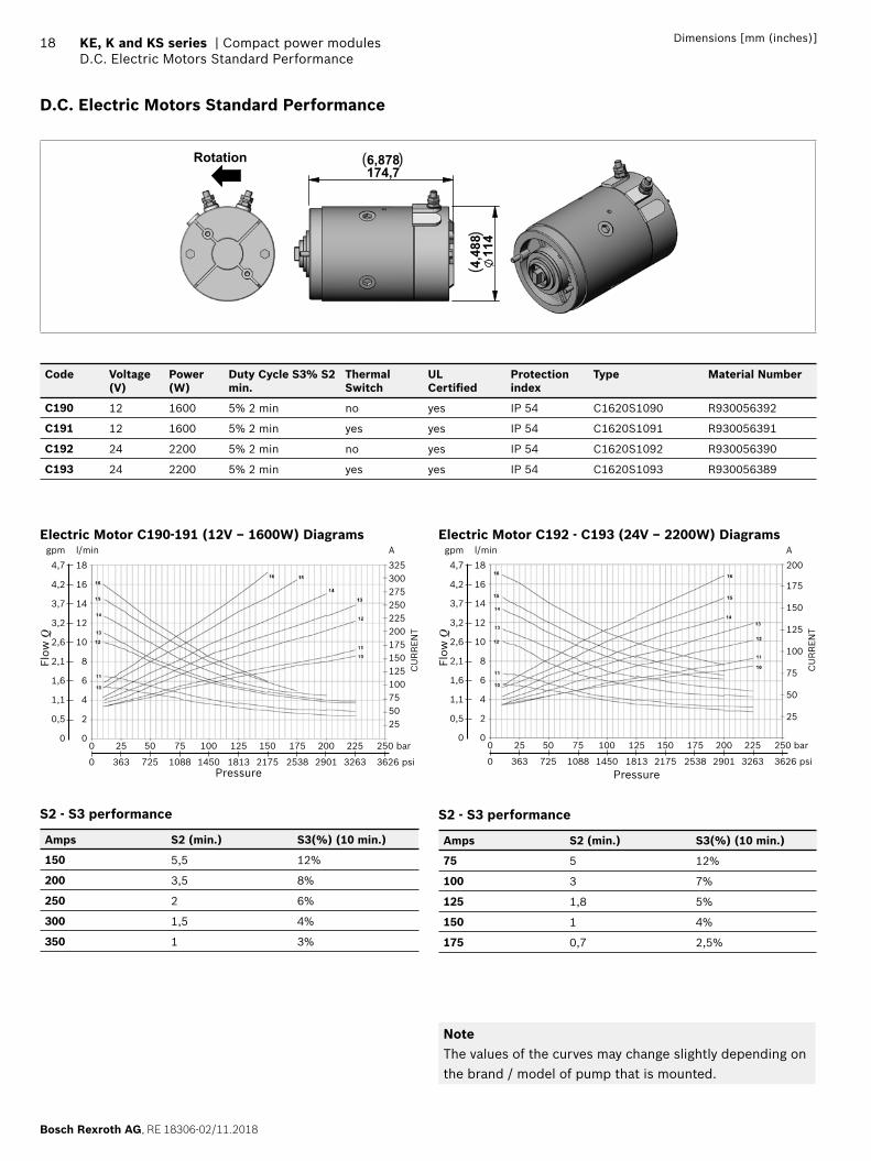
D.C. Electric Motors Standard Performance
6,878174,7
4,48
811
4
Rotation ( )
()
Code Voltage(V)
Power(W)
Duty Cycle S3% S2 min.
Thermal Switch
UL Certifi ed
Protection index
Type Material Number
C190 12 1600 5% 2 min no yes IP 54 C1620S1090 R930056392
C191 12 1600 5% 2 min yes yes IP 54 C1620S1091 R930056391
C192 24 2200 5% 2 min no yes IP 54 C1620S1092 R930056390
C193 24 2200 5% 2 min yes yes IP 54 C1620S1093 R930056389
Electric Motor C190-191 (12V – 1600W) Diagramsl/min
18
16
14
12
10
8
6
4
2
0
A
325300275250225200175150125100755025
0 25 50 75 100 125 150 175 200 225 250 bar
0 363 725 1088 1450 1813 2175 2538 2901 3263 3626 psi
gpm
4,7
4,2
3,7
3,2
2,6
2,1
1,6
1,1
0,5
0
Flow
Q
CU
RR
EN
T
Pressure
S2 - S3 performance
Amps S2 (min.) S3(%) (10 min.)
150 5,5 12%
200 3,5 8%
250 2 6%
300 1,5 4%
350 1 3%
Electric Motor C192 - C193 (24V – 2200W) Diagramsl/min
18
16
14
12
10
8
6
4
2
0
A
200
175
150
125
100
75
50
25
0 25 50 75 100 125 150 175 200 225 250 bar
0 363 725 1088 1450 1813 2175 2538 2901 3263 3626 psi
gpm
4,7
4,2
3,7
3,2
2,6
2,1
1,6
1,1
0,5
0
Flow
Q
CU
RR
EN
T
Pressure
S2 - S3 performance
Amps S2 (min.) S3(%) (10 min.)
75 5 12%
100 3 7%
125 1,8 5%
150 1 4%
175 0,7 2,5%
NoteThe values of the curves may change slightly depending on the brand / model of pump that is mounted.
RE 18306-02/11.2018, Bosch Rexroth AG
Compact power modules | KE, K and KS series Relay
19Dimensions [mm (inches)]
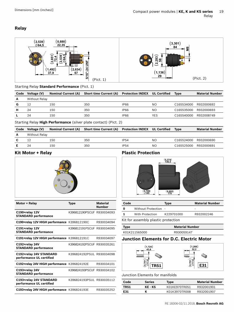
Relay
672,634
64,5
2,53
972
,42,
851
5/16
"-24
UN
F
22,350,880
64,52,539
37,91,492
( )
( )
( )
( )
()
()
(Pict. 1)
843,301
291,136
582,283
M8
( )
( )
()
(Pict. 2)
Starting Relay Standard Performance (Pict. 1)
Code Voltage (V) Nominal Current (A) Short time Current (A) Protection INDEX UL Certifi ed Type Material Number
A Without Relay
G 12 150 350 IP66 NO C165534000 R932000692
H 24 150 350 IP66 NO C165535000 R932000693
L 24 150 350 IP66 YES C165540000 R932008749
Starting Relay High Performance (silver plate contact) (Pict. 2)
Code Voltage (V) Nominal Current (A) Short time Current (A) Protection INDEX UL Certifi ed Type Material Number
A Without Relay
C 12 150 350 IP54 NO C165524000 R932000690
E 24 150 350 IP54 NO C165525000 R932000691
Kit Motor + Relay
Motor + Relay Type Material Number
C190+relay 12V STANDARD performance
K396812190PSCUF R930034093
C190+relay 12V HIGH performance K396812190C R930034094
C191+relay 12V STANDARD performance
K396812191PSCUF R930034095
C191+relay 12V HIGH performance K396812191C R930034097
C192+relay 24V STANDARD performance
K396824192PSCUF R930035261
C192+relay 24V STANDARD performance UL certifi ed
K396824192PSUL R930034098
C192+relay 24V HIGH performance K396824192E R930034101
C193+relay 24V STANDARD performance
K396824193PSCUF R930034102
C193+relay 24V STANDARD performance UL certifi ed
K396824193PSUL R930035112
C193+relay 24V HIGH performance K396824193E R930035252
Plastic Protection
1706,693
136,55,374
1455,709
( )
( ) ( )
Code Type Material Number
0 Without Protection - -
1 With Protection K229701000 R932002246
Kit for assembly plastic protection
Type Material Number
K01K211565000 R930059147
Junction Elements for D.C. Electric Motor
17,8
0,701
43,81,724( )
()
TR51
17,8
0,701
32,21,268( )
()
E31
Junction Elements for manifolds
Code Series Type Material Number
TR51 KE - KS K01KE970TR051 R932001901E31 K K01K3970TR008 R932001907
Bosch Rexroth AG, RE 18306-02/11.2018
20 KE, K and KS series | Compact power modulesD.C. Electric Motors High Performance
Dimensions [mm (inches)]
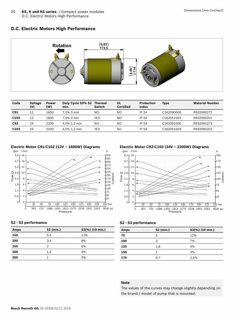
D.C. Electric Motors High Performance
114
4,49
173,56,83Rotation ( )
()
Code Voltage(V)
Power(W)
Duty Cycle S3% S2 min.
Thermal Switch
UL Certifi ed
Protection index
Type Material Number
C91 12 1600 7,5% 3 min NO NO IP 54 C162090000 R932000272
C102 12 1600 7,5% 3 min YES NO IP 54 C1620S1002 R932000201
C92 24 2200 4,5% 1,2 min NO NO IP 54 C162091000 R932000273
C103 24 2200 4,5% 1,2 min YES NO IP 54 C1620S1003 R932000202
Electric Motor C91-C102 (12V – 1600W) Diagramsl/min
16
14
12
10
8
6
4
2
0
A
350325300275250225200175150125100755025
0 25 50 75 100 125 150 175 200 225 250 bar
0 363 725 1088 1450 1813 2175 2538 2901 3263 3626 psi
gpm
4,2
3,7
3,2
2,6
2,1
1,6
1,1
0,5
0
Flow
Q
CU
RR
EN
T
Pressure
S2 - S3 performance
Amps S2 (min.) S3(%) (10 min.)
150 5,5 12%
200 3,5 8%
250 2 6%
300 1,5 4%
350 1 3%
Electric Motor C92-C103 (24V – 2200W) Diagrams
CU
RR
EN
T
l/min
16
14
12
10
8
6
4
2
00 25 50 75 100 125 150 175 200 225 250 bar
0 363 725 1088 1450 1813 2175 2538 2901 3263 3626 psi
gpm
4,2
3,7
3,2
2,6
2,1
1,6
1,1
0,5
0
Flow
Q
Pressure
A
200
175
150
125
100
75
50
25
S2 - S3 performance
Amps S2 (min.) S3(%) (10 min.)
75 5 12%
100 3 7%
125 1,8 5%
150 1 4%
175 0,7 2,5%
NoteThe values of the curves may change slightly depending on the brand / model of pump that is mounted.

RE 18306-02/11.2018, Bosch Rexroth AG
Compact power modules | KE, K and KS series Relay
21Dimensions [mm (inches)]
Relay
672,634
64,5
2,53
972
,42,
851
5/16
"-24
UN
F
22,350,880
64,52,539
37,91,492
( )
( )
( )
( )
()
()
(Pict. 1)
843,301
291,136
582,283
M8
( )
( )
()
(Pict. 2)
Starting Relay Standard Performance (Pict. 1)
Code Voltage (V) Nominal Current (A) Short time Current (A) Protection INDEX UL Certifi ed Type Material Number
A Without Relay
G 12 150 350 IP66 NO C165534000 R932000692
H 24 150 350 IP66 NO C165535000 R932000693
Starting Relay High Performance (silver plate contact) (Pict. 2)
Code Voltage (V) Nominal Current (A) Short time Current (A) Protection INDEX UL Certifi ed Type Material Number
A Without Relay
C 12 150 350 IP54 NO C165524000 R932000690
E 24 150 350 IP54 NO C165525000 R932000691
Kit Motor + Relay
Motor + Relay Type Material Number
C91+relay 12V STANDARD performance
K39681291PSCUF R932007960
C91+relay 12V HIGH performance
K39681291CF R932002749
C102+relay 12V STANDARD performance
K396812102PSCUF R932007969
C102+relay 12V HIGH performance
K396812102CF R932002715
C92+relay 24V STANDARD performance
K39682492PSCUF R932007961
C92+relay 24V HIGH performance
K39682492EF R932002818
C103+relay 24V STANDARD performance
K396824103PSCUF R932007968
C103+relay 24V HIGH performance
K396824103EF R932002771
Plastic Protection
1706,693
136,55,374
1455,709
( )
( ) ( )
Code Type Material Number
0 Without Protection - -
1 With Protection K229701000 R932002246
Kit for assembly plastic protection
Type Material Number
K01K211518000 R932009439
Junction Elements for D.C. Electric Motor
17,8
0,701
43,81,724( )
()
TR51
17,8
0,701
32,21,268( )
()
E31
Junction Elements for manifolds
Code Series Type Material Number
TR51 KE - KS K01KE970TR051 R932001901E31 K K01K3970TR008 R932001907
Bosch Rexroth AG, RE 18306-02/11.2018
22 KE, K and KS series | Compact power modulesD.C. Electric Motors Standard Performance Low Noise
Dimensions [mm (inches)]
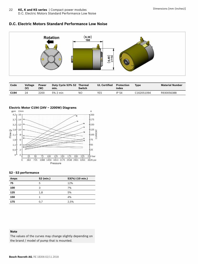
D.C. Electric Motors Standard Performance Low Noise
114
4,49
1606,30Rotation ( )
()
Code Voltage(V)
Power(W)
Duty Cycle S3% S2 min.
Thermal Switch
UL Certifi ed Protection index
Type Material Number
C194 24 2200 5% 2 min NO YES IP 54 C1620S1094 R930056388
Electric Motor C194 (24V – 2200W) Diagramsl/min
16
14
12
10
8
6
4
2
00 25 50 75 100 125 150 175 200 225 250 bar
0 363 725 1088 1450 1813 2175 2538 2901 3263 3626 psi
gpm
4,2
3,7
3,2
2,6
2,1
1,6
1,1
0,5
0
Flow
Q
CU
RR
EN
T
Pressure
A
200
175
150
125
100
75
50
25
S2 - S3 performance
Amps S2 (min.) S3(%) (10 min.)
75 5 12%
100 3 7%
125 1,8 5%
150 1 4%
175 0,7 2,5%
NoteThe values of the curves may change slightly depending on the brand / model of pump that is mounted.
RE 18306-02/11.2018, Bosch Rexroth AG
Compact power modules | KE, K and KS series Relay
23Dimensions [mm (inches)]
Relay
672,634
64,5
2,53
972
,42,
851
5/16
"-24
UN
F
22,350,880
64,52,539
37,91,492
( )
( )
( )
( )
()
()
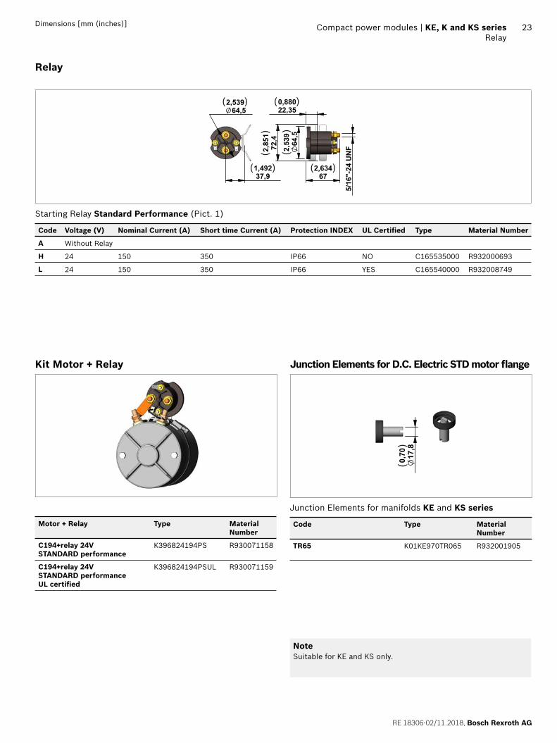
Starting Relay Standard Performance (Pict. 1)
Code Voltage (V) Nominal Current (A) Short time Current (A) Protection INDEX UL Certifi ed Type Material Number
A Without Relay
H 24 150 350 IP66 NO C165535000 R932000693
L 24 150 350 IP66 YES C165540000 R932008749
Kit Motor + Relay
Motor + Relay Type Material Number
C194+relay 24V STANDARD performance
K396824194PS R930071158
C194+relay 24V STANDARD performance UL certifi ed
K396824194PSUL R930071159
Junction Elements for D.C. Electric STD motor fl ange
17,8
0,70
()
Junction Elements for manifolds KE and KS series
Code Type Material Number
TR65 K01KE970TR065 R932001905
NoteSuitable for KE and KS only.
Bosch Rexroth AG, RE 18306-02/11.2018
24 KE, K and KS series | Compact power modulesD.C. Electric Motors High Performance Fan Cooled
Dimensions [mm (inches)]
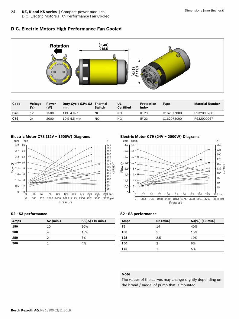
D.C. Electric Motors High Performance Fan Cooled
112,5
4,43
215,58,48Rotation ( )
()
Code Voltage(V)
Power(W)
Duty Cycle S3% S2 min.
Thermal Switch
UL Certifi ed
Protection index
Type Material Number
C78 12 1500 14% 4 min NO NO IP 23 C162077000 R932000266
C79 24 2000 10% 4,5 min NO NO IP 23 C162078000 R932000267
Electric Motor C78 (12V – 1500W) Diagramsl/min
16
14
12
10
8
6
4
2
0
A
375350325300275250225200175150125100755025
0 25 50 75 100 125 150 175 200 225 250 bar
0 363 725 1088 1450 1813 2175 2538 2901 3263 3626 psi
gpm
4,2
3,7
3,2
2,6
2,1
1,6
1,1
0,5
0
Flow
Q
CU
RR
EN
T
Pressure
S2 - S3 performance
Amps S2 (min.) S3(%) (10 min.)
150 10 30%
200 4 15%
250 2 7%
300 1 4%
Electric Motor C79 (24V – 2000W) Diagramsl/min
16
14
12
10
8
6
4
2
0
A
250
225
200
175
150
125
100
75
50
25
0 25 50 75 100 125 150 175 200 225 250 bar
0 363 725 1088 1450 1813 2175 2538 2901 3263 3626 psi
gpm
4,2
3,7
3,2
2,6
2,1
1,6
1,1
0,5
0
Flow
Q
CU
RR
EN
T
Pressure
S2 - S3 performance
Amps S2 (min.) S3(%) (10 min.)
75 14 40%
100 5 15%
125 3,5 10%
150 2 6%
175 1 5%
NoteThe values of the curves may change slightly depending on the brand / model of pump that is mounted.
RE 18306-02/11.2018, Bosch Rexroth AG
Compact power modules | KE, K and KS series Relay
25Dimensions [mm (inches)]
Relay
672,634
64,5
2,53
972
,42,
851
5/16
"-24
UN
F
22,350,880
64,52,539
37,91,492
( )
( )
( )
( )
()
()
(Pict. 1)
843,301
291,136
582,283
M8
( )
( )
()
(Pict. 2)
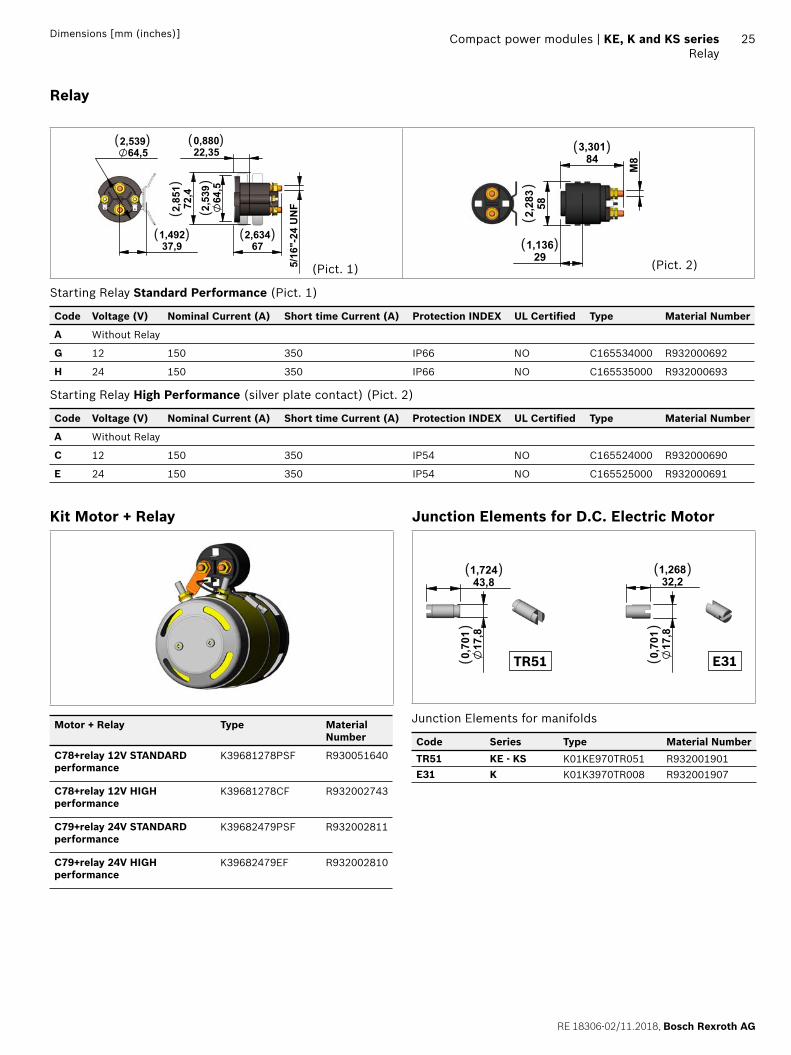
Starting Relay Standard Performance (Pict. 1)
Code Voltage (V) Nominal Current (A) Short time Current (A) Protection INDEX UL Certifi ed Type Material Number
A Without Relay
G 12 150 350 IP66 NO C165534000 R932000692
H 24 150 350 IP66 NO C165535000 R932000693
Starting Relay High Performance (silver plate contact) (Pict. 2)
Code Voltage (V) Nominal Current (A) Short time Current (A) Protection INDEX UL Certifi ed Type Material Number
A Without Relay
C 12 150 350 IP54 NO C165524000 R932000690
E 24 150 350 IP54 NO C165525000 R932000691
Kit Motor + Relay
Motor + Relay Type Material Number
C78+relay 12V STANDARD performance
K39681278PSF R930051640
C78+relay 12V HIGH performance
K39681278CF R932002743
C79+relay 24V STANDARD performance
K39682479PSF R932002811
C79+relay 24V HIGH performance
K39682479EF R932002810
Junction Elements for D.C. Electric Motor
17,8
0,701
43,81,724( )
()
TR51
17,8
0,701
32,21,268( )
()
E31
Junction Elements for manifolds
Code Series Type Material Number
TR51 KE - KS K01KE970TR051 R932001901E31 K K01K3970TR008 R932001907
Bosch Rexroth AG, RE 18306-02/11.2018
26 KE, K and KS series | Compact power modulesD.C. Electric Motors Standard Performance
Dimensions [mm (inches)]
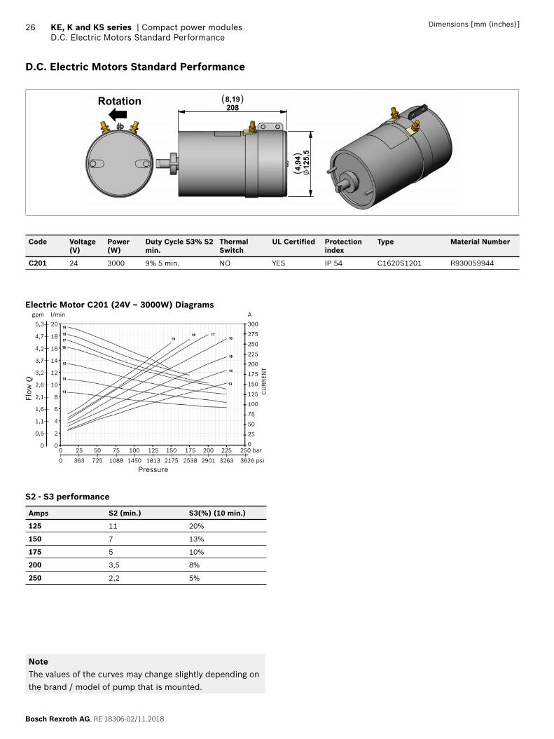
D.C. Electric Motors Standard Performance
2088,19
125,5
4,94
Rotation ( )
()
Code Voltage(V)
Power(W)
Duty Cycle S3% S2 min.
Thermal Switch
UL Certifi ed Protection index
Type Material Number
C201 24 3000 9% 5 min. NO YES IP 54 C1620S1201 R930059944
Electric Motor C201 (24V – 3000W) Diagramsl/min
20
18
16
14
12
10
8
6
4
2
0
A
300
275
250
225
200
175
150
125
100
75
50
25
00 25 50 75 100 125 150 175 200 225 250 bar
0 363 725 1088 1450 1813 2175 2538 2901 3263 3626 psi
gpm
5,3
4,7
4,2
3,7
3,2
2,6
2,1
1,6
1,1
0,5
0
Flow
Q
CU
RR
EN
T
Pressure
S2 - S3 performance
Amps S2 (min.) S3(%) (10 min.)
125 11 20%
150 7 13%
175 5 10%
200 3,5 8%
250 2,2 5%
NoteThe values of the curves may change slightly depending on the brand / model of pump that is mounted.
RE 18306-02/11.2018, Bosch Rexroth AG
Compact power modules | KE, K and KS series Relay
27Dimensions [mm (inches)]
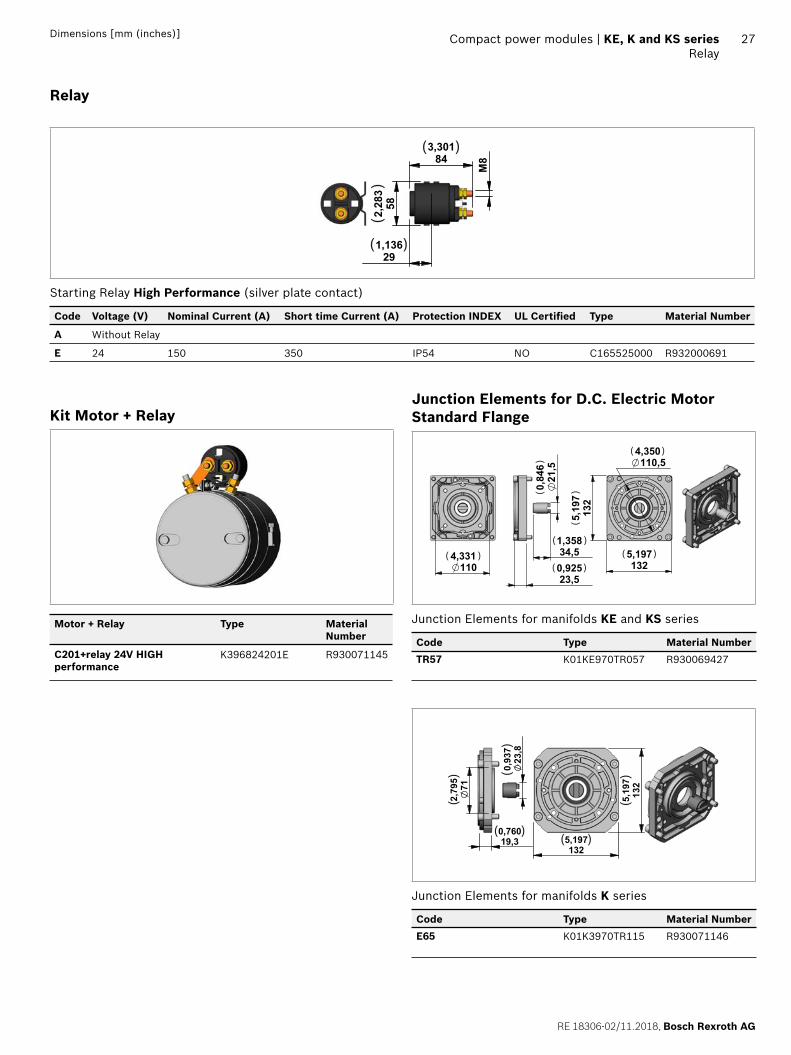
Relay
843,301
291,136
582,283
M8
( )
( )
()
Starting Relay High Performance (silver plate contact)
Code Voltage (V) Nominal Current (A) Short time Current (A) Protection INDEX UL Certifi ed Type Material Number
A Without Relay
E 24 150 350 IP54 NO C165525000 R932000691
Kit Motor + Relay
Motor + Relay Type Material Number
C201+relay 24V HIGH performance
K396824201E R930071145
Junction Elements for D.C. Electric Motor Standard Flange
34,51,35821,5
0,846
23,50,925110
4,3311325,197
132
5,197
110,54,350
( )
()
( )
( )( )
( )
()
Junction Elements for manifolds KE and KS series
Code Type Material Number
TR57 K01KE970TR057 R930069427
712,795
19,30,760
23,8
0,937
132
5,197
1325,197
( )
()
( )
()
()
Junction Elements for manifolds K series
Code Type Material Number
E65 K01K3970TR115 R930071146
Bosch Rexroth AG, RE 18306-02/11.2018
28 KE, K and KS series | Compact power modulesD.C. Electric Motors Low Noise High Performance
Dimensions [mm (inches)]
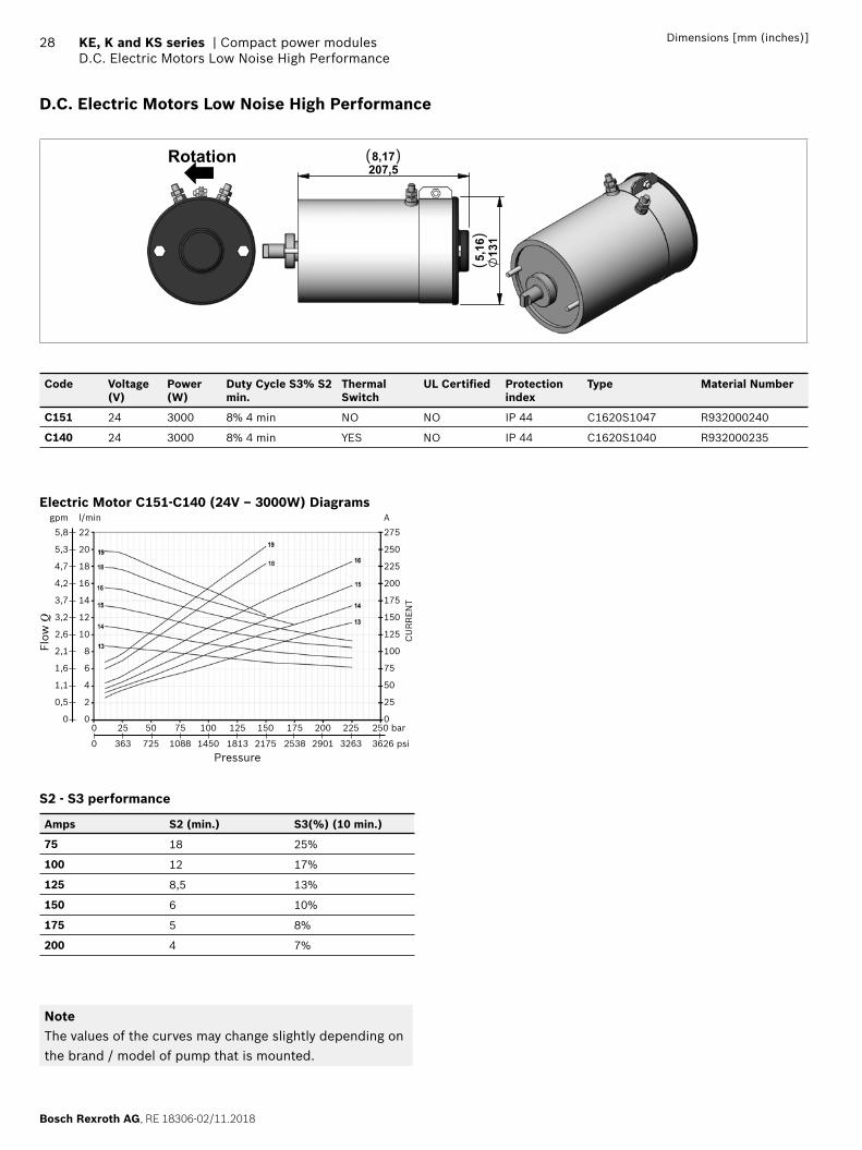
D.C. Electric Motors Low Noise High Performance
131
5,16
207,58,17Rotation ( )
()
Code Voltage(V)
Power(W)
Duty Cycle S3% S2 min.
Thermal Switch
UL Certifi ed Protection index
Type Material Number
C151 24 3000 8% 4 min NO NO IP 44 C1620S1047 R932000240
C140 24 3000 8% 4 min YES NO IP 44 C1620S1040 R932000235
Electric Motor C151-C140 (24V – 3000W) Diagramsl/min
22
20
18
16
14
12
10
8
6
4
2
0
A
275
250
225
200
175
150
125
100
75
50
25
00 25 50 75 100 125 150 175 200 225 250 bar
0 363 725 1088 1450 1813 2175 2538 2901 3263 3626 psi
gpm
5,8
5,3
4,7
4,2
3,7
3,2
2,6
2,1
1,6
1,1
0,5
0
Flow
Q
CU
RR
EN
T
Pressure
S2 - S3 performance
Amps S2 (min.) S3(%) (10 min.)
75 18 25%
100 12 17%
125 8,5 13%
150 6 10%
175 5 8%
200 4 7%
NoteThe values of the curves may change slightly depending on the brand / model of pump that is mounted.
RE 18306-02/11.2018, Bosch Rexroth AG
Compact power modules | KE, K and KS series Relay
29Dimensions [mm (inches)]
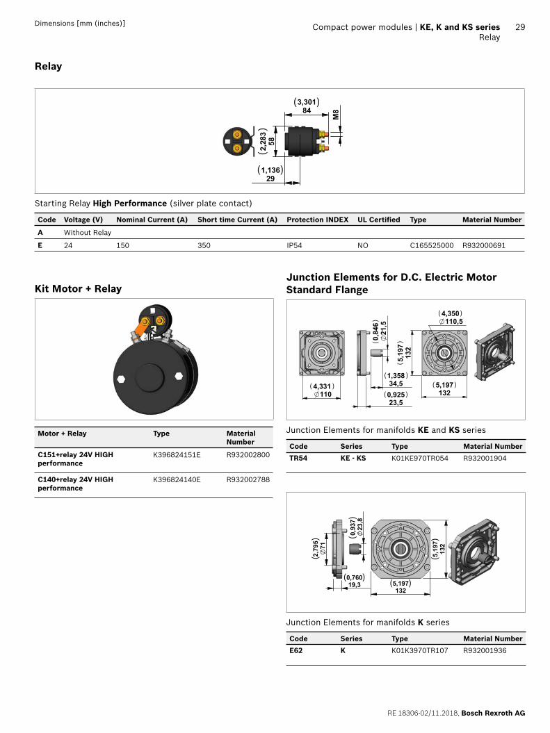
Relay
843,301
291,136
582,283
M8
( )
( )
()
Starting Relay High Performance (silver plate contact)
Code Voltage (V) Nominal Current (A) Short time Current (A) Protection INDEX UL Certifi ed Type Material Number
A Without Relay
E 24 150 350 IP54 NO C165525000 R932000691
Kit Motor + Relay
Motor + Relay Type Material Number
C151+relay 24V HIGH performance
K396824151E R932002800
C140+relay 24V HIGH performance
K396824140E R932002788
Junction Elements for D.C. Electric Motor Standard Flange
34,51,35821,5
0,846
23,50,925110
4,3311325,197
132
5,197
110,54,350
( )
()
( )
( )( )
( )
()
Junction Elements for manifolds KE and KS series
Code Series Type Material Number
TR54 KE - KS K01KE970TR054 R932001904
712,795
19,30,760
23,8
0,937
132
5,197
1325,197
( )
()
( )
()
()
Junction Elements for manifolds K series
Code Series Type Material Number
E62 K K01K3970TR107 R932001936
Bosch Rexroth AG, RE 18306-02/11.2018
30 KE, K and KS series | Compact power modulesD.C. Electric Motors High Performance Fan Cooled
Dimensions [mm (inches)]
D.C. Electric Motors High Performance Fan Cooled
131
5,16
2349,21Rotation ( )
()
Code Voltage(V)
Power(W)
Duty Cycle S3% S2 min.
Thermal Switch
UL Certifi ed Protection index
Type Material Number
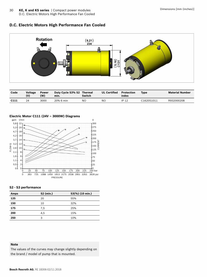
C111 24 3000 20% 6 min NO NO IP 12 C1620S1011 R932000208
Electric Motor C111 (24V – 3000W) Diagramsl/min
22
20
18
16
14
12
10
8
6
4
2
00 25 50 75 100 125 150 175 200 225 250 bar
0 363 725 1088 1450 1813 2175 2538 2901 3263 3626 psi
gpm
5,8
5,3
4,7
4,2
3,7
3,2
2,6
2,1
1,6
1,1
0,5
0
FLO
W-Q
CU
RR
EN
T
PRESSURE
A
300
275
250
225
200
175
150
125
100
75
50
25
0
S2 - S3 performance
Amps S2 (min.) S3(%) (10 min.)
125 20 55%
150 10 32%
175 7,5 25%
200 4,5 15%
250 3 10%
NoteThe values of the curves may change slightly depending on the brand / model of pump that is mounted.
RE 18306-02/11.2018, Bosch Rexroth AG
Compact power modules | KE, K and KS series Relay
31Dimensions [mm (inches)]
Relay
843,301
291,136
582,283
M8
( )
( )
()
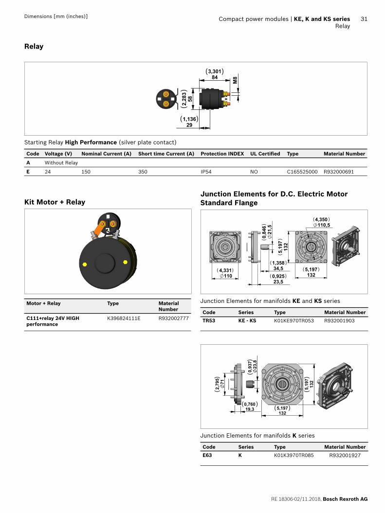
Starting Relay High Performance (silver plate contact)
Code Voltage (V) Nominal Current (A) Short time Current (A) Protection INDEX UL Certifi ed Type Material Number
A Without Relay
E 24 150 350 IP54 NO C165525000 R932000691
Kit Motor + Relay
Motor + Relay Type Material Number
C111+relay 24V HIGH performance
K396824111E R932002777
Junction Elements for D.C. Electric Motor Standard Flange
34,51,35821,5
0,846
23,50,925110
4,3311325,197
132
5,197
110,54,350
( )
()
( )
( )( )
( )
()
Junction Elements for manifolds KE and KS series
Code Series Type Material Number
TR53 KE - KS K01KE970TR053 R932001903
712,795
19,30,760
23,8
0,937
132
5,197
1325,197
( )
()
( )
()
()
Junction Elements for manifolds K series
Code Series Type Material Number
E63 K K01K3970TR085 R932001927
Bosch Rexroth AG, RE 18306-02/11.2018
32 KE, K and KS series | Compact power modulesCentral Manifold KE
Dimensions [mm (inches)]
Central Manifold KE
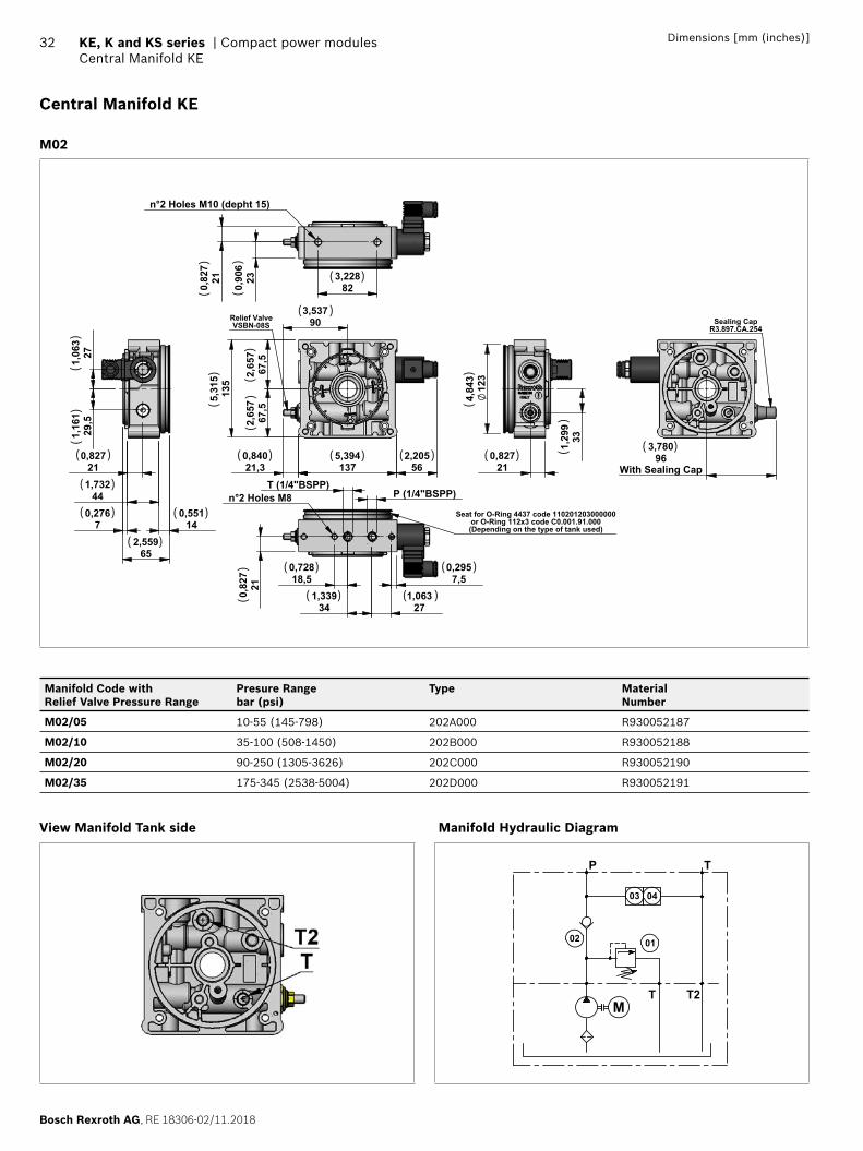
M02
2,205
56 5,394137
0,84021,3
2,
657
67,5
2,65
767
,5
5,31
513
5
3,53790Relief Valve
VSBN-08S
P (1/4"BSPP) T (1/4"BSPP)
n°2 Holes M8
0,295
7,5
0,82
721
0,72818,5
1,339
34 1,063
27
Seat for O-Ring 4437 code 110201203000000or O-Ring 112x3 code C0.001.91.000(Depending on the type of tank used)
0,827
21 4,
843
123
1,
299
33
0,55114
0,82721
2,559
65
0,2767
1,73244
1,
063
27
1,16
129
,5
3,228
82 0,90
6230,82
721
n°2 Holes M10 (depht 15)
3,78096
With Sealing Cap
Sealing CapR3.897.CA.254
( )
()
( )
( ) ( )
( )
( )
( )
( )
( )
( ) ( ) ( )
( )
( )
( )
()
()(
) ()
()
()
()
()
( )
()
Manifold Code with Relief Valve Pressure Range
Presure Rangebar (psi)
Type MaterialNumber
M02/05 10-55 (145-798) 202A000 R930052187
M02/10 35-100 (508-1450) 202B000 R930052188
M02/20 90-250 (1305-3626) 202C000 R930052190
M02/35 175-345 (2538-5004) 202D000 R930052191
View Manifold Tank side Manifold Hydraulic Diagram
MT2T
02 01
03
TP
04
RE 18306-02/11.2018, Bosch Rexroth AG
Compact power modules | KE, K and KS series Central Manifold KE
33Dimensions [mm (inches)]
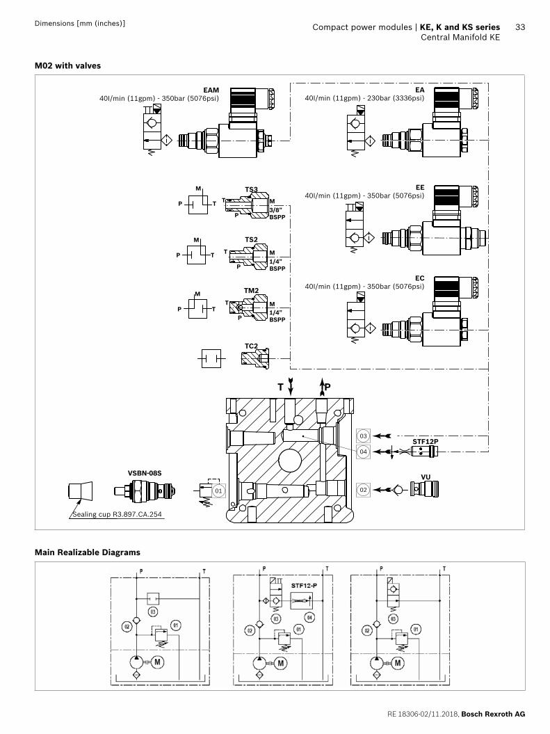
M02 with valves
03
04
0201
EAM40I/min (11gpm) - 350bar (5076psi)
EA40I/min (11gpm) - 230bar (3336psi)
EE40I/min (11gpm) - 350bar (5076psi)
EC40I/min (11gpm) - 350bar (5076psi)
STF12P
VSBN-08S VU
Sealing cup R3.897.CA.254
TS3
P
P
T T
M
M3/8”BSPP
P
P
T T
M
M
M
1/4”BSPP
PP
TT
M
1/4”BSPP
TS2
TM2
TC2
PT
Main Realizable Diagrams
Bosch Rexroth AG, RE 18306-02/11.2018
34 KE, K and KS series | Compact power modulesCentral Manifold KE
Dimensions [mm (inches)]
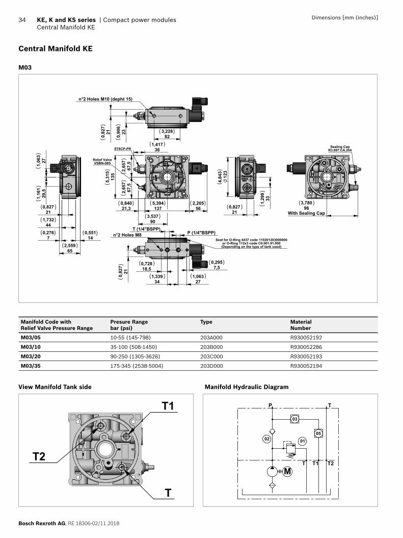
Central Manifold KE
M03
2,205
56 5,394137
0,84021,3
2,
657
67,5
2,
657
67,5
5,31
513
5
3,53790
1,41736
Relief ValveVSBN-08S
ST6CP-PR
P (1/4"BSPP) T (1/4"BSPP)
n°2 Holes M8
0,295
7,5
0,82
721
0,72818,5
1,339
34 1,063
27
Seat for O-Ring 4437 code 110201203000000or O-Ring 112x3 code C0.001.91.000(Depending on the type of tank used)
0,82721
4,84
312
3
1,29
933
0,55114
0,82721
2,559
65
0,2767
1,73244
1,06
327
1,16
129
,5
3,228
82 0,90
6230,82
721
n°2 Holes M10 (depht 15)
3,78096
With Sealing Cap
Sealing CapR3.897.CA.254
( )
()
( )
( ) ( )( )
( )
( )( )
( )
( )
( ) ( )
( ) ( )
( )( )
( )()(
)(
)
()
()
()
()
()
()
Manifold Code with Relief Valve Pressure Range
Presure Rangebar (psi)
Type MaterialNumber
M03/05 10-55 (145-798) 203A000 R930052192
M03/10 35-100 (508-1450) 203B000 R930052286
M03/20 90-250 (1305-3626) 203C000 R930052193
M03/35 175-345 (2538-5004) 203D000 R930052194
View Manifold Tank side
T2
T
T1
Manifold Hydraulic Diagram
MT1 T2T
02 0105
03
TP
RE 18306-02/11.2018, Bosch Rexroth AG
Compact power modules | KE, K and KS series Central Manifold KE
35Dimensions [mm (inches)]
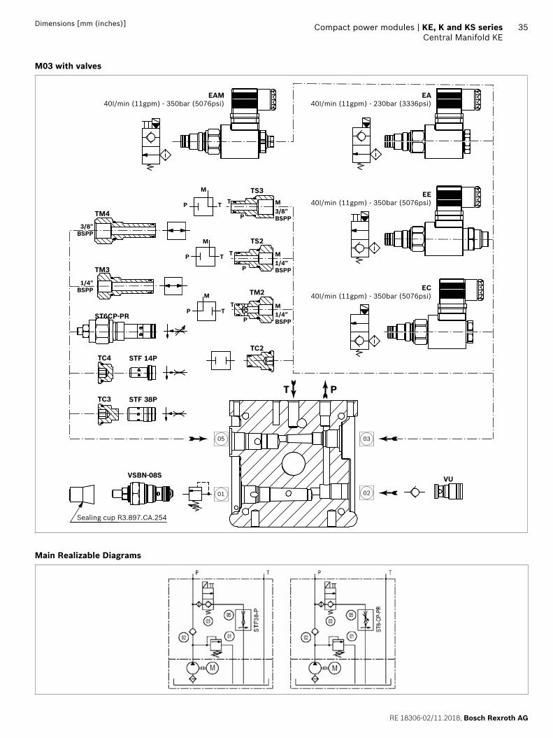
M03 with valves
03
0201
05
EAM40I/min (11gpm) - 350bar (5076psi)
EA40I/min (11gpm) - 230bar (3336psi)
EE40I/min (11gpm) - 350bar (5076psi)
EC40I/min (11gpm) - 350bar (5076psi)
VU
Sealing cup R3.897.CA.254
TS3
TM4
TM3
TC4
ST6CP-PR
STF 14P
TC3 STF 38P
P
P
T T
M
M3/8”BSPP
3/8”BSPP
1/4”BSPP
P
P
T T
M
M
M
1/4”BSPP
PP
TT
M
1/4”BSPP
TS2
TM2
TC2
PT
VSBN-08S
Main Realizable Diagrams
Bosch Rexroth AG, RE 18306-02/11.2018
36 KE, K and KS series | Compact power modulesCentral Manifold KE
Dimensions [mm (inches)]
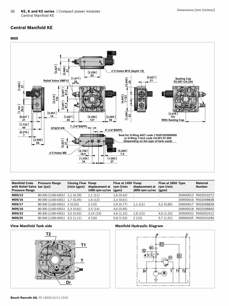
Central Manifold KE
M09
1,41736
2,65
767
,52,
657
67,5
5,31
513
5
1,02726
5,394137
2,20556
Relief Valve VMP12
0,2957,5
1,063
271,339
34
0,72818,5
P (1/4"BSPP) T (1/4"BSPP)
0,82
721
n°2 Holes M8
Seat for O-Ring 4437 code 110201203000000or O-Ring 112x3 code C0.001.91.000(Depending on the type of tank used)
ST6CP-PR
0,82721
4,84
312
3240,94
5331,29
9
0,82721
1,73244
0,551
14
0,2767
2,559
65
1,06
327
1,16
129
,5
3,228
82
0,90
623
0,
827
21 n°2 Holes M10 (depht 15)
3,976101
With Sealing Cap
Sealing CapR3.897.CA.254
( )
()
( )
( ) ( )
( )
( )( )
( )
( )
( )
( )
( ) ( )
( )( )
( )
()(
)(
)
()
()
()
()
()
()
()
Manifold Code with Relief Valve Pressure Range
Pressure Range bar (psi)
Closing Flowl/min (gpm)
Pump displacement at 1450 rpm cc/rev
Flow at 1450 rpm l/min (gpm)
Pump displacement at 2850 rpm cc/rev
Flow at 2850 rpm l/min (gpm)
Type Material Number
M09/13 80-300 (1160-4351) 1,1 (0,29) 1,1 (11) 1,6 (0,42) - - 209I00013 R932010272M09/16 80-300 (1160-4351) 1,7 (0,45) 1,6 (12) 2,3 (0,61) - - 209I00016 R932008838 M09/17 80-300 (1160-4351) 2 (0,53) 2 (13) 2,9 (0,77) 1,1 (11) 3,2 (0,85) 209I00017 R932008839 M09/18 80-300 (1160-4351) 2,3 (0,61) 2,5 (14) 3,6 (0,95) - - 209I00018 R932008840M09/22 80-300 (1160-4351) 3,5 (0,92) 3,15 (15) 4,6 (1,22) 1,6 (12) 4,6 (1,22) 209I00022 R930052412M09/25 80-300 (1160-4351) 4,2 (1,11) 4 (16) 5,8 (1,53) 2 (13) 5,7 (1,51) 209I00025 R932010299
View Manifold Tank side
Dr
T
T1
T2
Manifold Hydraulic Diagram
TP
MDr T T1 T2
01
03
0502
04
RE 18306-02/11.2018, Bosch Rexroth AG
Compact power modules | KE, K and KS series Central Manifold KE
37Dimensions [mm (inches)]
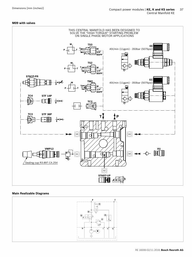
M09 with valves
03
0401
05
02
EE40I/min (11gpm) - 350bar (5076psi)
EC40I/min (11gpm) - 350bar (5076psi)
VMP12 VU
START-UP
Sealing cup R3.897.CA.254
TS3
TC4
ST6CP-PR
STF 14P
TC3 STF 38P
P
P
T T
M
M3/8”BSPP
P
P
T T
M
M
M
1/4”BSPP
PP
TT
M
1/4”BSPP
TS2
TM2
TC2
PT
THIS CENTRAL MANIFOLD HAS BEEN DESIGNED TOSOLVE THE "HIGH TORQUE" STARTING PROBLEM
ON SINGLE PHASE MOTOR APPLICATIONS
Main Realizable Diagrams
02
TP
MDr T T1 T2
01
03
05
04
Bosch Rexroth AG, RE 18306-02/11.2018
38 KE, K and KS series | Compact power modulesCentral Manifold KE
Dimensions [mm (inches)]
Central Manifold KE
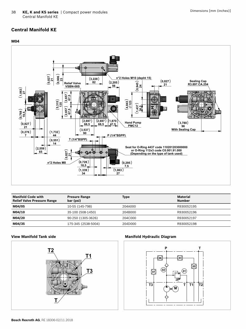
M04
3,537
90
2,65
767
,5
2,65
767
,5
5,31
513
5
1,87047,5
2,20556
2,69768,5
2,69768,5
Relief ValveVSBN-08S
Hand PumpPMC12
P (1/4"BSPP) T (1/4"BSPP)
0,295
7,5 1,063
271,339
34
0,72818,5
0,
827
21
n°2 Holes M8
Seat for O-Ring 4437 code 110201203000000or O-Ring 112x3 code C0.001.91.000(Depending on the type of tank used)
4,84
312
3
0,82721
1,43
736
,5
0,94
524
0,82721
0,2767
1,73244
0,55114
2,55965
19,5
0,76
81,
063
27
3,228
82 0,82
721 0,90
623
n°2 Holes M10 (depht 15)
3,78096
With Sealing Cap
Sealing CapR3.897.CA.254
( )(
)( ) ( )
( )
( )
( )
( )
( )
( )
( )
( )
( )
( ) ( )
( )
()
()
()
()
()
()
()
()
()
( )
( )
()
Manifold Code with Relief Valve Pressure Range
Presure Rangebar (psi)
Type MaterialNumber
M04/05 10-55 (145-798) 204A000 R930052195
M04/10 35-100 (508-1450) 204B000 R930052196
M04/20 90-250 (1305-3626) 204C000 R930052197
M04/35 175-345 (2538-5004) 204D000 R930052198
View Manifold Tank side
T2T1
T3
T
Manifold Hydraulic Diagram
M
P T
06
07
03
050102
T3 T T2T1
RE 18306-02/11.2018, Bosch Rexroth AG
Compact power modules | KE, K and KS series Central Manifold KE
39Dimensions [mm (inches)]
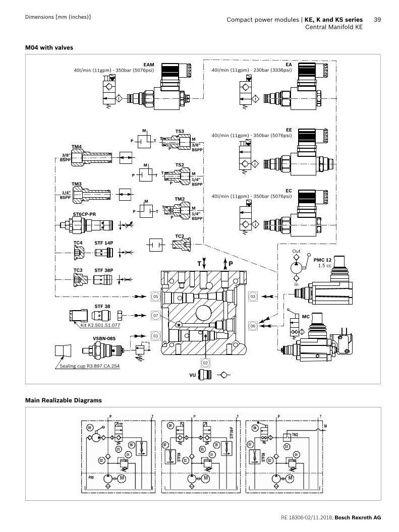
M04 with valves
03
06
01
05
02
07
STF 38
Sealing cup R3.897.CA.254
TS3
TM4
TM3
TC4
ST6CP-PR
STF 14P
TC3 STF 38P
P
P
T T
M
M3/8”BSPP
3/8”BSPP
1/4”BSPP
P
P
T T
M
M
M
1/4”BSPP
PP
TT
M
1/4”BSPP
TS2
TM2
TC2
PTPMC 12
1.5 cc
MC
Out
In
VU
Kit K2.501.S1.077
VSBN-08S
EAM40I/min (11gpm) - 350bar (5076psi)
EA40I/min (11gpm) - 230bar (3336psi)
EE40I/min (11gpm) - 350bar (5076psi)
EC40I/min (11gpm) - 350bar (5076psi)
Main Realizable Diagrams
Bosch Rexroth AG, RE 18306-02/11.2018
40 KE, K and KS series | Compact power modulesCentral Manifold KE
Dimensions [mm (inches)]
Central Manifold KE
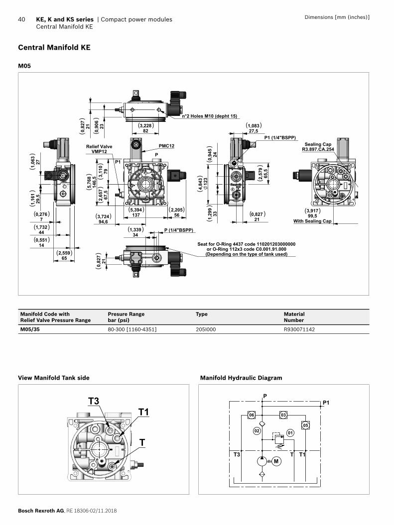
M05
1375,394
67,5
2,65
7793,11
014
6,5
5,76
8
2,205
56 3,72494,6
Relief ValveVMP12
PMC12
PP1
P (1/4"BSPP)
210,82
7
341,339
Seat for O-Ring 4437 code 110201203000000or O-Ring 112x3 code C0.001.91.000(Depending on the type of tank used)
210,827
123
4,84
3
P1 (1/4"BSPP)27,51,083
240,94
5
65,5
2,57
9
1,
299
337
0,276
441,732
140,551
652,559
29,5
1,16
1
1,06
327
823,228230,
906
210,82
7
n°2 Holes M10 (depht 15)
3,91799,5
With Sealing Cap
Sealing CapR3.897.CA.254
( )(
)
( )
( )
( )
( )
( )
( )
( )
( )( ) ( )
( )
()
()
()
()
()
()
()
()
()
()
()
Manifold Code with Relief Valve Pressure Range
Presure Rangebar (psi)
Type MaterialNumber
M05/35 80-300 [1160-4351] 205I000 R930071142
View Manifold Tank side
T
T1T3
Manifold Hydraulic Diagram
M
P
06 03
050102
T3 T T1
P1
RE 18306-02/11.2018, Bosch Rexroth AG
Compact power modules | KE, K and KS series Central Manifold KE
41Dimensions [mm (inches)]
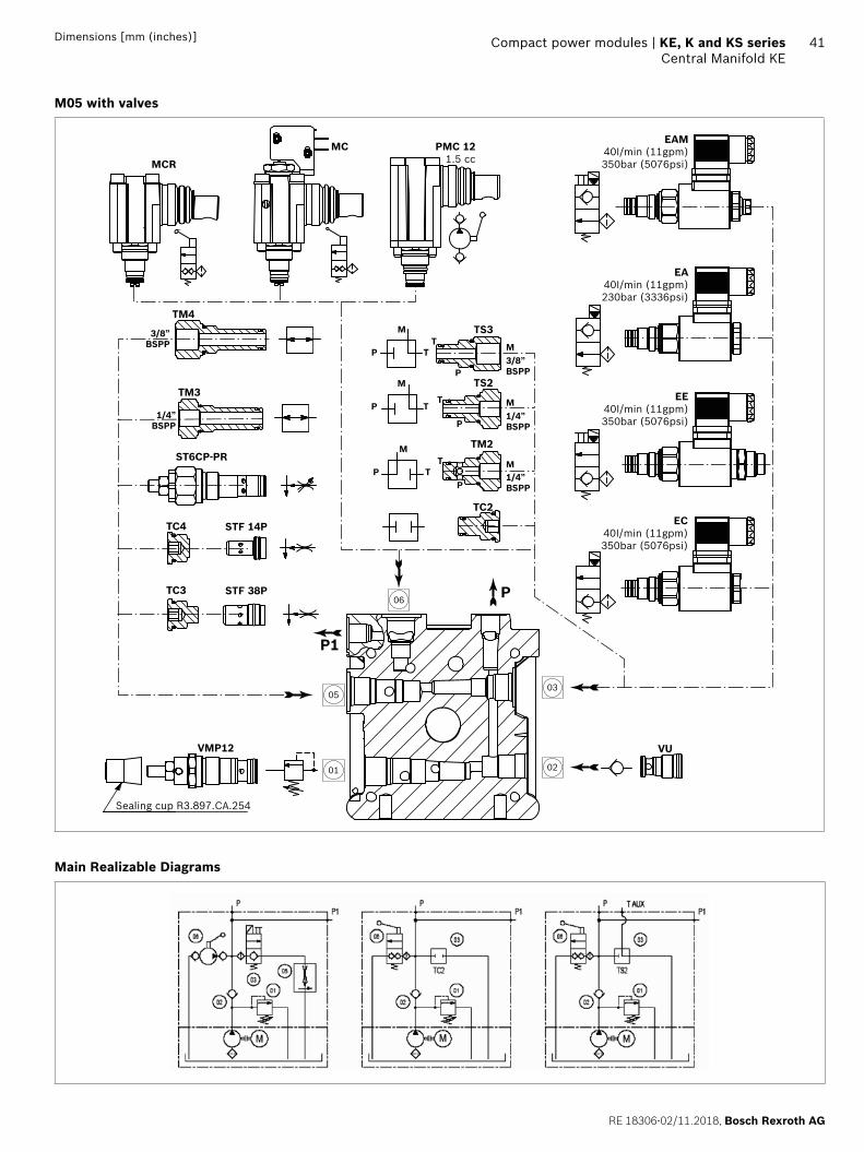
M05 with valves
03
0201
05
06
EAM40I/min (11gpm)350bar (5076psi)
EA40I/min (11gpm)230bar (3336psi)
EE40I/min (11gpm)350bar (5076psi)
EC40I/min (11gpm)350bar (5076psi)
TS3TM4
TM3
TC4
ST6CP-PR
STF 14P
TC3 STF 38P
P
P
TT
M
M3/8”BSPP
3/8”BSPP
1/4”BSPP
P
P
TT
M
M
M
1/4”BSPP
PP
TT
M
1/4”BSPP
TS2
TM2
TC2
P
P1
PMC 121.5 cc
MC
MCR
VU
Sealing cup R3.897.CA.254
VMP12
Main Realizable Diagrams
Bosch Rexroth AG, RE 18306-02/11.2018
42 KE, K and KS series | Compact power modulesCentral Manifold KE
Dimensions [mm (inches)]
Central Manifold KE
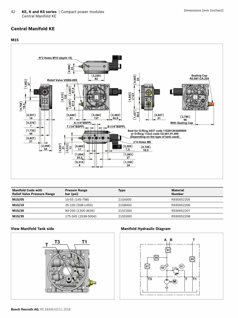
M15
62,62,465
1375,394
67,5
2,65
767
,52,
657
135
5,31
5
0,840
21
Relief Valve VSBN-08S
B (1/4"BSPP)A (1/4"BSPP)
T (1/4"BSPP)
271,063
341,339
18,50,728
170,669
25,51,004
7,50,295
130,51
2210,82
7
80,315
n°4 Holes M8
Seat for O-Ring 4437 code 110201203000000or O-Ring 112x3 code C0.001.91.000(Depending on the type of tank used)
210,827
123
4,84
3
36,5
1,43
7240,94
5
210,827
140,551
441,732
70,276
652,559
19,5
0,76
8
271,06
3
N°2 Holes M10 (depht 15)
823,228
230,90
6
3,780
96 With Sealing Cap
Sealing CapR3.897.CA.254
( )
( )
( )
( )
( )
( ) ( )
( )
( ) ( )
( )
( ) ( )
( ) ( )( )( )( )
()
()
() (
)
()
()
()
()
()
()
()
Manifold Code with Relief Valve Pressure Range
Presure Rangebar (psi)
Type MaterialNumber
M15/05 10-55 (145-798) 215A000 R930052205
M15/10 35-100 (508-1450) 215B000 R930052206
M15/20 90-250 (1305-3626) 215C000 R930052207
M15/35 175-345 (2538-5004) 215D000 R930052208
View Manifold Tank side
T T3 T1
Manifold Hydraulic Diagram
M
07 02
03
06
01
05
A B T
T3 T T1
RE 18306-02/11.2018, Bosch Rexroth AG
Compact power modules | KE, K and KS series Central Manifold KE
43Dimensions [mm (inches)]
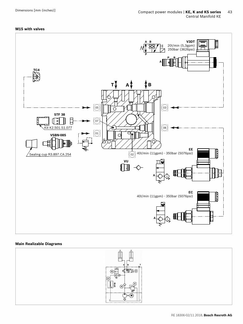
M15 with valves
03
06
01
05
02
07
V3DT20I/min (5,3gpm)250bar (3626psi)
VU
TC4
A
A
B
BP
P
BT A
STF 38
Kit K2.501.S1.077
Sealing cup R3.897.CA.254
VSBN-08S
EE40I/min (11gpm) - 350bar (5076psi)
EC40I/min (11gpm) - 350bar (5076psi)
AP
AP
Main Realizable Diagrams

Bosch Rexroth AG, RE 18306-02/11.2018
44 KE, K and KS series | Compact power modulesCentral Manifold KE
Dimensions [mm (inches)]
Central Manifold KE
M16
62,62,465
1375,394
27,31,075
67,5
2,65
767
,52,
657
135
5,31
5
120,472
Relief Valve VSBN-08S
B (1/4"BSPP)T (1/4"BSPP)
271,063
341,339
18,50,728
170,669
25,51,004
7,50,295
130,51
2
210,82
7
80,315
n°4 Holes M8
Seat for O-Ring 4437 code 110201203000000or O-Ring 112x3 code C0.001.91.000(Depending on the type of tank used)
123
4,84
321
0,827
A 1/4" BSPP
36,5
1,43
7240,94
5
210,827
140,551
441,732
70,276
652,559
19,5
0,76
8
271,06
3
823,228230,
906
210,82
7 n°2 Holes M10 (depht 15)
3,780
96 With Sealing Cap
Sealing CapR3.897.CA.254
( )
( )
( ) ( ) ( ) ( ) ( ) ( )
( )
( )
( )( )
( )
( )( )
( )
( ) ( )( )
()
()
()
() (
)
()
() (
)(
)(
)
()
()
Manifold Code with Relief Valve Pressure Range
Presure Rangebar (psi)
Type MaterialNumber
M16/05 10-55 (145-798) 216A000 R930052212
M16/10 35-100 (508-1450) 216B000 R930052213
M16/20 90-250 (1305-3626) 216C000 R930052214
M16/35 175-345 (2538-5004) 216D000 R930052215
View Manifold Tank side
T T3T2
Manifold Hydraulic Diagram
B T
M
01
03
06
07 02
T3 T T2
A
RE 18306-02/11.2018, Bosch Rexroth AG
Compact power modules | KE, K and KS series Central Manifold KE
45Dimensions [mm (inches)]
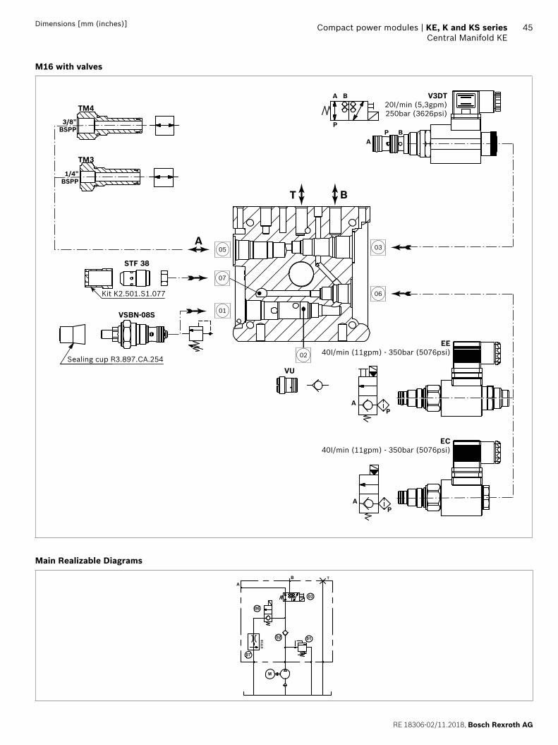
M16 with valves
AP
AP
03
06
01
05
02
07
V3DT20I/min (5,3gpm)250bar (3626psi)
VU
A
A
B
BP
P
BT
STF 38
Kit K2.501.S1.077
Sealing cup R3.897.CA.254
A
TM4
TM3
3/8”BSPP
1/4”BSPP
VSBN-08S
EE40I/min (11gpm) - 350bar (5076psi)
EC40I/min (11gpm) - 350bar (5076psi)
Main Realizable Diagrams
AB T
M
0102
03
06
07
STF38
Bosch Rexroth AG, RE 18306-02/11.2018
46 KE, K and KS series | Compact power modulesCentral Manifold KE
Dimensions [mm (inches)]
Central Manifold KE
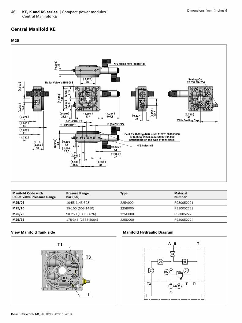
M25
2,
657
67,5
2,65
767
,5
5,394137
0,84021,33
4,244107,8
5,31
513
5
Relief Valve VSBN-08S
B (1/4"BSPP) A (1/4"BSPP)
T (1/4"BSPP)
0,2957,5
1,06327
1,33934
N°3 holes M8 0,90
623
0,2957,5
1,00425,5
0,669
17
1,39835,5
Seat for O-Ring 4437 code 110201203000000or O-Ring 112x3 code C0.001.91.000(Depending on the type of tank used)
0,82721
1,43
736
,5
0,2767
0,551
14 0,827
21
1,732
44
2,559
65
19,5
0,76
81,
063
27
0,90
623
3,228
82
N°2 Holes M10 (depht 15)
3,780
96With Sealing Cap
Sealing CapR3.897.CA.254
( )
( )( )( )( )
( )
( )
( )
( )( )
( )
( )
( ) ( )
( )
( )
( ) ( )
()
()
() (
) ()
()
()
()
Manifold Code with Relief Valve Pressure Range
Presure Rangebar (psi)
Type MaterialNumber
M25/05 10-55 (145-798) 225A000 R930052221
M25/10 35-100 (508-1450) 225B000 R930052222
M25/20 90-250 (1305-3626) 225C000 R930052223
M25/35 175-345 (2538-5004) 225D000 R930052224
View Manifold Tank side
T1
T3
T
Manifold Hydraulic Diagram
M
07 02
03
06
01
A B T
05
T3 T T1
RE 18306-02/11.2018, Bosch Rexroth AG
Compact power modules | KE, K and KS series Central Manifold KE
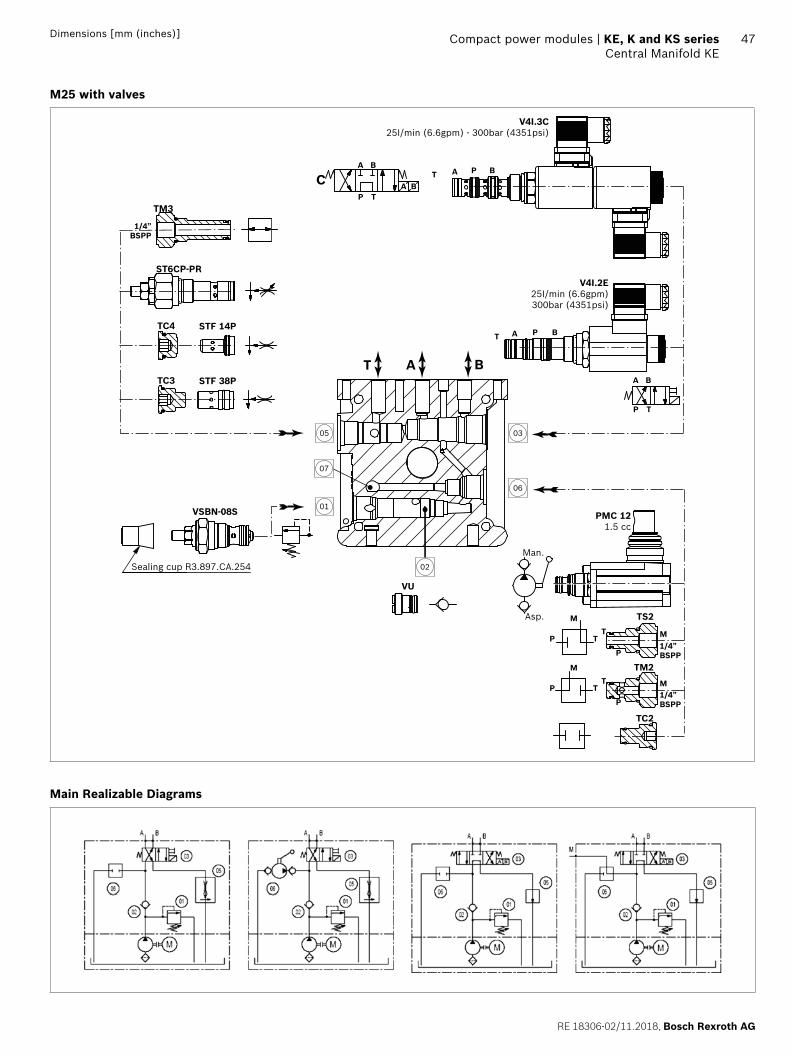
47Dimensions [mm (inches)]
M25 with valves
03
06
01
05
02
07
VU
BAT
Sealing cup R3.897.CA.254
PMC 121.5 cc
TS2
TM2
TC2
P
P
TT
M
M
M
1/4”BSPP
1/4”BSPP
P
P
TT
M
Man.
Asp.
A B
A B
P T
C
A B
P T
AT BP
AT BP
V4I.3C 25I/min (6.6gpm) - 300bar (4351psi)
V4I.2E25I/min (6.6gpm)300bar (4351psi)
TM3
TC4
ST6CP-PR
STF 14P
TC3 STF 38P
1/4”BSPP
VSBN-08S
Main Realizable Diagrams
Bosch Rexroth AG, RE 18306-02/11.2018
48 KE, K and KS series | Compact power modulesCentral Manifold KE
Dimensions [mm (inches)]
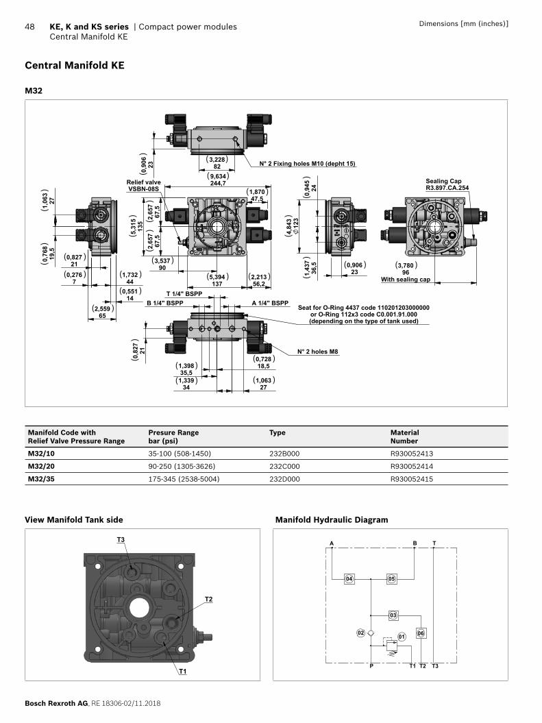
Central Manifold KE
M32
5,394137
3,537
90
5,
315
135
2,
657
67,5
2,
657
67,5
2,21356,2
9,634244,7
1,87047,5
Relief valveVSBN-08S
4,84
312
3
1,43
736
,5
0,94
524
0,906
23 0,2767
1,73244
0,551
14
2,559
65
1,06
327
0,76
819
,5
0,82721
A 1/4" BSPP T 1/4" BSPP
B 1/4" BSPP
0,82
721
0,72818,5
1,339
34 1,063
27
1,39835,5
N° 2 holes M8
Seat for O-Ring 4437 code 110201203000000or O-Ring 112x3 code C0.001.91.000(depending on the type of tank used)
3,228
82 0,90
623 N° 2 Fixing holes M10 (depht 15)
3,78096
With sealing cap
Sealing CapR3.897.CA.254
( )
( )
( )
( ) ( )( ) ( )
( )
( )
( )
( )
( )
( )( )
( )( )
()
()
()
()
()
()
()
()
()
()
( )
Manifold Code with Relief Valve Pressure Range
Presure Rangebar (psi)
Type MaterialNumber
M32/10 35-100 (508-1450) 232B000 R930052413
M32/20 90-250 (1305-3626) 232C000 R930052414
M32/35 175-345 (2538-5004) 232D000 R930052415
View Manifold Tank side
T1
T2
T3
Manifold Hydraulic Diagram
TA B
P T1 T2 T3
0102
03
0504
06
RE 18306-02/11.2018, Bosch Rexroth AG
Compact power modules | KE, K and KS series Central Manifold KE
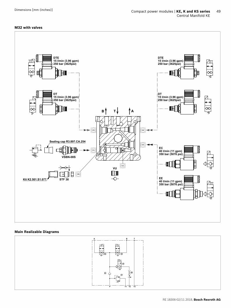
49Dimensions [mm (inches)]
M32 with valves
04
03
01
05
02
06
ATB
EC40 l/min (11 gpm)350 bar (5076 psi)
EE40 l/min (11 gpm)350 bar (5076 psi)
VU
VSBN-08S
DTE15 l/min (3.96 gpm)250 bar (3625psi)
DT15 l/min (3.96 gpm)250 bar (3625psi)
DTE15 l/min (3.96 gpm)250 bar (3625psi)
DT15 l/min (3.96 gpm)250 bar (3625psi)
Sealing cap R3.897.CA.254
STF 38Kit K2.501.S1.077
Main Realizable Diagrams
04 05
03
0201
T3T2T1P
BA T
06
Bosch Rexroth AG, RE 18306-02/11.2018
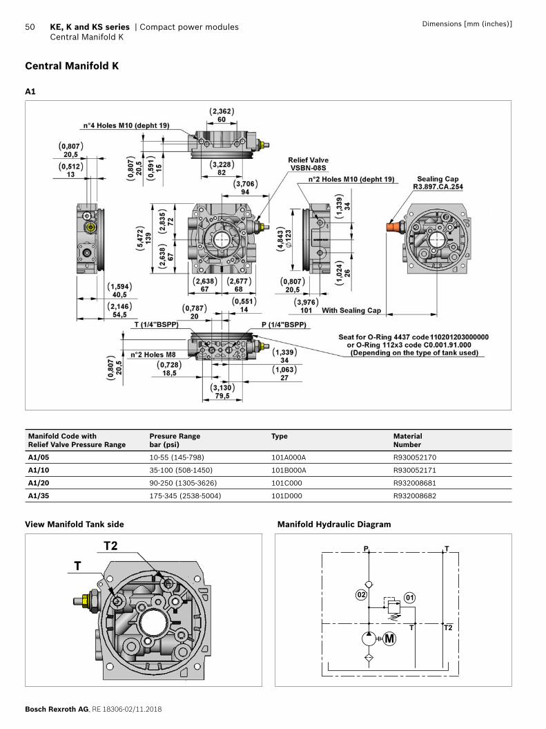
50 KE, K and KS series | Compact power modulesCentral Manifold K
Dimensions [mm (inches)]
Central Manifold K
A1
Manifold Code with Relief Valve Pressure Range
Presure Rangebar (psi)
Type MaterialNumber
A1/05 10-55 (145-798) 101A000A R930052170
A1/10 35-100 (508-1450) 101B000A R930052171
A1/20 90-250 (1305-3626) 101C000 R932008681
A1/35 175-345 (2538-5004) 101D000 R932008682
View Manifold Tank side Manifold Hydraulic Diagram
MT2T
02 01
TP
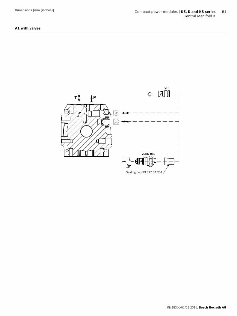
RE 18306-02/11.2018, Bosch Rexroth AG
Compact power modules | KE, K and KS series Central Manifold K
51Dimensions [mm (inches)]
A1 with valves
Sealing cup R3.897.CA.254
VSBN-08S
VU
T P
02
01
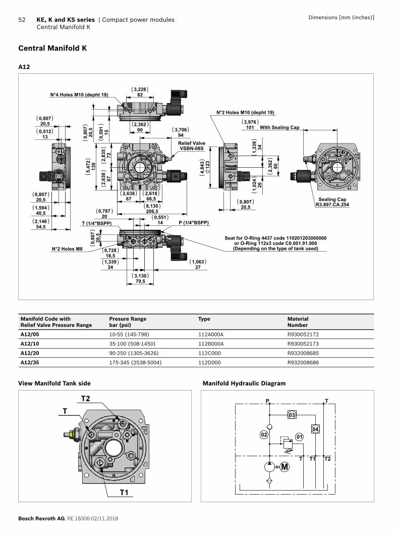
Bosch Rexroth AG, RE 18306-02/11.2018
52 KE, K and KS series | Compact power modulesCentral Manifold K
Dimensions [mm (inches)]
Central Manifold K
A12
3,70694
2,638
67 2,61866,5
2,63
867
2,83
572
5,47
213
9
8,130206,5
Relief ValveVSBN-08S
0,80
720
,5
0,72818,5
1,339
34
3,13079,5
1,063
27
N°2 Holes M8
P (1/4"BSPP) T (1/4"BSPP) 0,551
14
0,78720
Seat for O-Ring 4437 code 110201203000000or O-Ring 112x3 code C0.001.91.000(Depending on the type of tank used)
N°2 Holes M10 (depht 19)
2,
362
60
0,80720,5
4,84
312
3
1,
339
34
1,
024
26
0,51213
0,80720,5
0,80720,5
1,59440,5
2,14654,5
3,976101 With Sealing Cap
Sealing CapR3.897.CA.254
3,228
82
2,362
60
0,80
720
,5
0,
591
15
N°4 Holes M10 (depht 19) ( )
( )
( )
( ) ( )
( )
( )
( )
( )
( )
( )
( )
( )
( )
( )
( )
()
()
()
()
()
()
()
()
()
()
( )
( )
( )
Manifold Code with Relief Valve Pressure Range
Presure Rangebar (psi)
Type MaterialNumber
A12/05 10-55 (145-798) 112A000A R930052172
A12/10 35-100 (508-1450) 112B000A R930052173
A12/20 90-250 (1305-3626) 112C000 R932008685
A12/35 175-345 (2538-5004) 112D000 R932008686
View Manifold Tank side Manifold Hydraulic Diagram
MT1 T2T
02 0104
03
TP
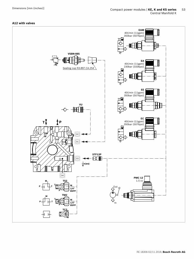
RE 18306-02/11.2018, Bosch Rexroth AG
Compact power modules | KE, K and KS series Central Manifold K
53Dimensions [mm (inches)]
A12 with valves
Sealing cup R3.897.CA.254
P
P
TT
M
M
M
1/4”BSPP
PP
TT
M
1/4”BSPP
TS2
TM2
TC2
PT
PMC 121.5 cc
STF12P
VSBN-08S
Out
In
VU
EAM40I/min (11gpm)350bar (5076psi)
EA40I/min (11gpm)230bar (3336psi)
EE40I/min (11gpm)350bar (5076psi)
EC40I/min (11gpm)350bar (5076psi)
02
01
03
04
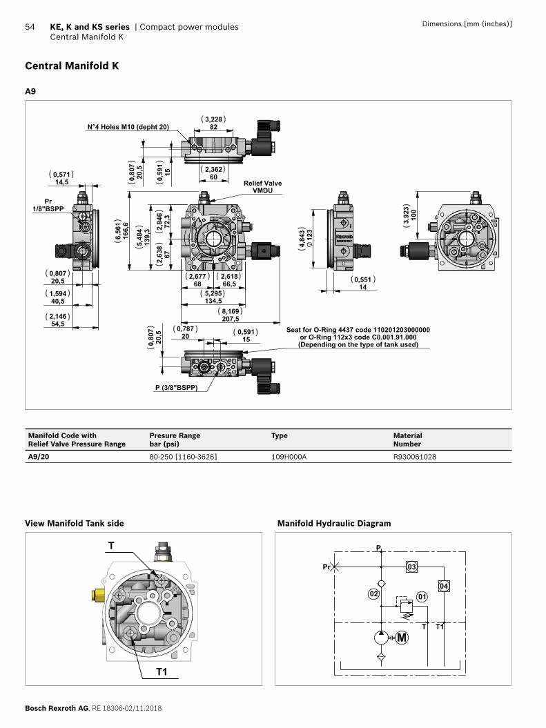
Bosch Rexroth AG, RE 18306-02/11.2018
54 KE, K and KS series | Compact power modulesCentral Manifold K
Dimensions [mm (inches)]
Central Manifold K
A9
2,677
68 2,61866,5
5,295134,5
2,
846
72,3
2,63
867
8,169207,5
5,
484
139,
3
6,56
116
6,6
Relief ValveVMDU
0,80
720
,5
0,78720 0,591
15
P (3/8"BSPP)
Seat for O-Ring 4437 code 110201203000000or O-Ring 112x3 code C0.001.91.000(Depending on the type of tank used)
0,551
14
4,84
312
3
Pr1/8"BSPP
0,57114,5
2,14654,5
0,80720,5
1,59440,5
3,
923
100
2,362
60
3,228
82
0,59
115
0,80
720
,5 N°4 Holes M10 (depht 20)
( )( )
( )
( )
( )( ) ( )
( )
( )
( )
( )
()
()
()
()
()
()
()
() (
)
( )
( )
Manifold Code with Relief Valve Pressure Range
Presure Rangebar (psi)
Type MaterialNumber
A9/20 80-250 [1160-3626] 109H000A R930061028
View Manifold Tank side
T
T1
Manifold Hydraulic Diagram
MT1T
02 0104
03
P
Pr
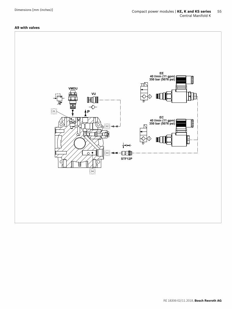
RE 18306-02/11.2018, Bosch Rexroth AG
Compact power modules | KE, K and KS series Central Manifold K
55Dimensions [mm (inches)]
A9 with valves
VU
VMDU
EE40 l/min (11 gpm)350 bar (5076 psi)
STF12P
EC40 l/min (11 gpm)350 bar (5076 psi)
02
03
04
01 P
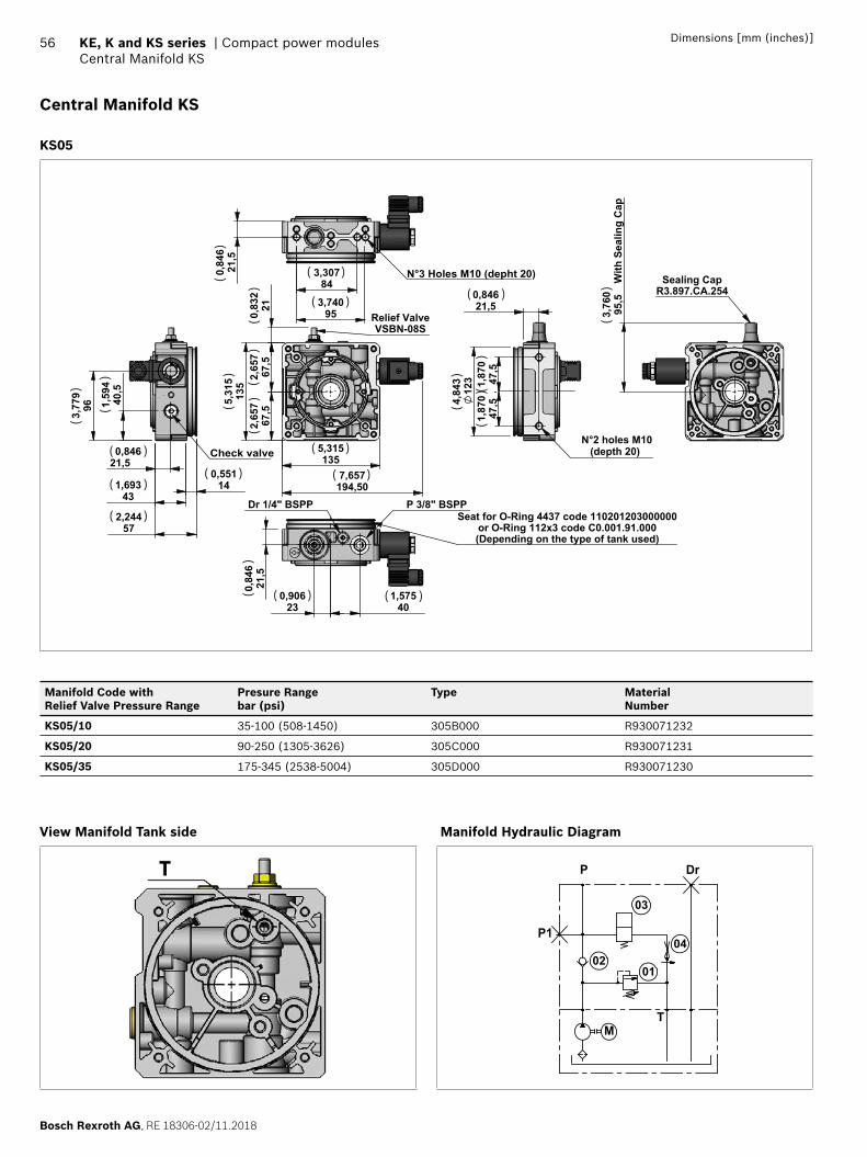
Bosch Rexroth AG, RE 18306-02/11.2018
56 KE, K and KS series | Compact power modulesCentral Manifold KS
Dimensions [mm (inches)]
Central Manifold KS
KS05
0,83
221
2,
657
67,5
2,65
767
,5
5,
315
135
7,657
194,50
5,315135
Relief ValveVSBN-08S
Dr 1/4" BSPP P 3/8" BSPP
0,906
23 1,575
40
0,84
621
,5
Seat for O-Ring 4437 code 110201203000000or O-Ring 112x3 code C0.001.91.000(Depending on the type of tank used)
4,84
312
3
N°2 holes M10 (depth 20)
0,84621,5
1,
870
47,5
1,87
047
,5
1,69343
2,24457
0,55114
3,77
996 1,
594
40,5
0,846
21,5 Check valve
3,76
095
,5 W
ith S
ealin
g C
ap
Sealing CapR3.897.CA.254
0,84
621
,5
3,307
84
3,74095
N°3 Holes M10 (depht 20)
( )
( )
( )
( )
( )
( )
( )
( )
( )
()
()
()
()
()
()
()
()
()
( )
( )
()(
)
()
Manifold Code with Relief Valve Pressure Range
Presure Rangebar (psi)
Type MaterialNumber
KS05/10 35-100 (508-1450) 305B000 R930071232
KS05/20 90-250 (1305-3626) 305C000 R930071231
KS05/35 175-345 (2538-5004) 305D000 R930071230
View Manifold Tank side Manifold Hydraulic Diagram
M
P1
P Dr
T
0201
03
04
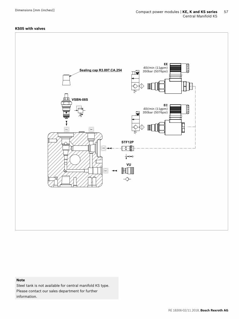
RE 18306-02/11.2018, Bosch Rexroth AG
Compact power modules | KE, K and KS series Central Manifold KS
57Dimensions [mm (inches)]
KS05 with valves
02
03
01 04
Sealing cap R3.897.CA.254
STF12P
VU
VSBN-08S
EE40I/min (11gpm)350bar (5076psi)
EC40I/min (11gpm)350bar (5076psi)
NoteSteel tank is not available for central manifold KS type. Please contact our sales department for further information.
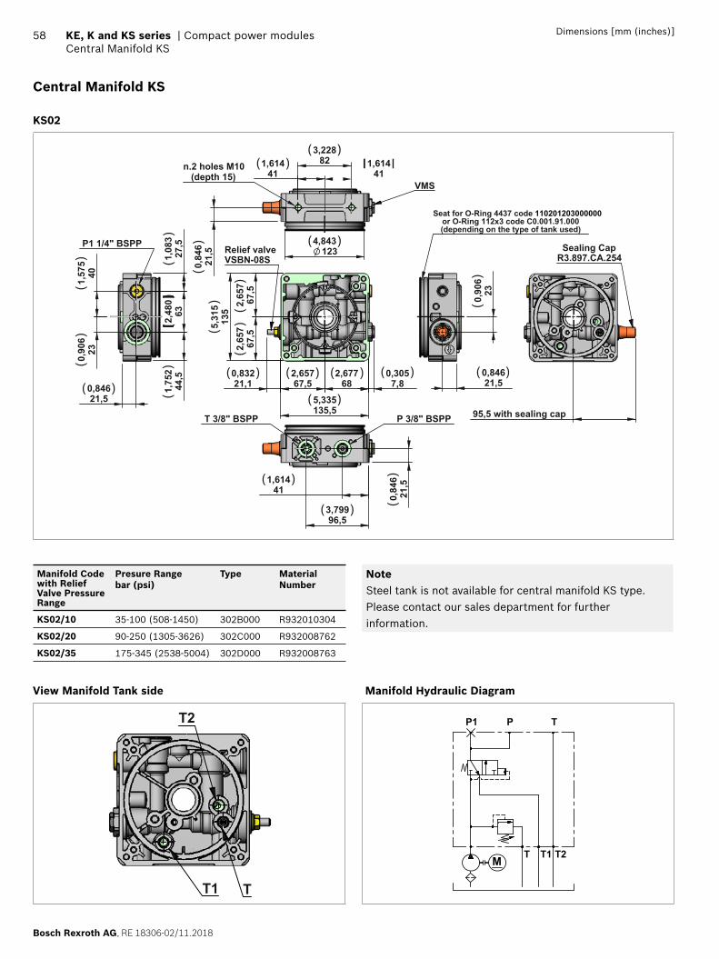
Bosch Rexroth AG, RE 18306-02/11.2018
58 KE, K and KS series | Compact power modulesCentral Manifold KS
Dimensions [mm (inches)]
Central Manifold KS
KS02
2,677
68 2,65767,5
0,83221,1
0,3057,8
5,335135,5
5,
315
135
2,
657
67,5
2,65
767
,5
Relief valve VSBN-08S
4,843123
n.2 holes M10 (depth 15)
3,228
82
1,61441
1,61441
0,
846
21,5
VMS
P 3/8" BSPP
1,614
41
0,
846
21,5
3,79996,5
T 3/8" BSPP
0,84621,5
0,
906
23
Seat for O-Ring 4437 code 110201203000000or O-Ring 112x3 code C0.001.91.000(depending on the type of tank used)
0,84621,5
1,75
244
,5
2,
480
63
1,
083
27,5
P1 1/4" BSPP
1,
575
40
0,
906
23
95,5 with sealing cap
Sealing CapR3.897.CA.254
( )( )
( )
( )( )
( ) ( ) ( ) ( )
( )
( )
( )
() (
)
()
()
()
()
()
()
()
()
()
Manifold Code with Relief Valve Pressure Range
Presure Rangebar (psi)
Type MaterialNumber
KS02/10 35-100 (508-1450) 302B000 R932010304
KS02/20 90-250 (1305-3626) 302C000 R932008762
KS02/35 175-345 (2538-5004) 302D000 R932008763
View Manifold Tank side
TT1
T2
NoteSteel tank is not available for central manifold KS type. Please contact our sales department for further information.
Manifold Hydraulic Diagram
M
P1
T T1
P T
T2
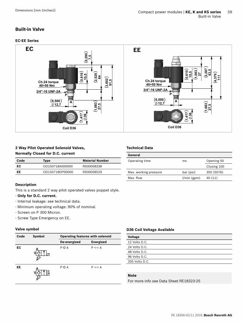
RE 18306-02/11.2018, Bosch Rexroth AG
Compact power modules | KE, K and KS series Built-in Valve
59Dimensions [mm (inches)]
Built-in Valve
EC-EE Series
2,
520
64
3,
602
91,5
1,08
327
,5
0,29
57,
5
0,50012,7
0,
610
15,5
Ch.24 torque 40÷50 Nm
3/4"-16 UNF-2A
A
P
1,41
736
Coil D36
( )(
)
()
()
()
()
()EC
0,50012,7
1,08
327
,5
0,
610
15,5
1,
063
27
3,
287
83,5
4,
370
111
Ch.24 torque 40÷50 Nm
3/4"-16 UNF-2A
A
P
1,41
736
Coil D36
( )
()
()
()
()
()
()
EE
2 Way Pilot Operated Solenoid Valves, Normally Closed for D.C. current
Code Type Material Number
EC OD150718A000000 R930058338
EE OD150718DP00000 R930058529
DescriptionThis is a standard 2 way pilot operated valves poppet style.- Only for D.C. current.- Internal leakage: see technical data.- Minimum operating voltage: 90% of nominal.- Screen on P 300 Micron.- Screw Type Emergency on EE.
Valve symbol
Code Symbol Operating features with solenoid
De-energized Energized
EC
P
A P A P <-> A
EE
P
A P A P <-> A
Technical Data
General
Operating time ms Opening 50
Closing 100
Max. working pressure bar (psi) 350 (5076)
Max. fl ow l/min (gpm) 40 (11)
D36 Coil Voltage Available
Voltage
12 Volts D.C.
24 Volts D.C.
48 Volts D.C.
96 Volts D.C.
205 Volts D.C.
NoteFor more info see Data Sheet RE18323-25
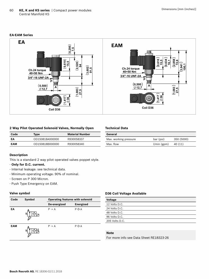
Bosch Rexroth AG, RE 18306-02/11.2018
60 KE, K and KS series | Compact power modulesCentral Manifold KS
Dimensions [mm (inches)]
EA-EAM Series
0,
610
15,5
0,29
57,
52,
520
64
3,60
291
,5
1,08
327
,5
0,50012,7
Ch.24 torque 40÷50 Nm 3/4"-16 UNF-2A
A
P
1,41
736
Coil D36
( )
()
()
()
()
()
()EA
0,50012,7
0,
610
15,5
0,
634
16,1
1,
083
27,5
2,
858
72,6
3,
941
100,
1
Ch.24 torque 40÷50 Nm
3/4"-16 UNF-2A
A
P
1,41
736
Coil D36
( )
()
()
()
()
()
()
EAM
2 Way Pilot Operated Solenoid Valves, Normally Open
Code Type Material Number
EA OD150818A000000 R930058337
EAM OD150818B000000 R930058340
DescriptionThis is a standard 2 way pilot operated valves poppet style.- Only for D.C. current.- Internal leakage: see technical data.- Minimum operating voltage: 90% of nominal.- Screen on P 300 Micron.- Push Type Emergency on EAM.
Valve symbol
Code Symbol Operating features with solenoid
De-energized Energized
EA
P
A P -> A P A
EAM
P
A P -> A P A
Technical Data
General
Max. working pressure bar (psi) 350 (5000)
Max. fl ow l/min (gpm) 40 (11)
D36 Coil Voltage Available
Voltage
12 Volts D.C.
24 Volts D.C.
48 Volts D.C.
96 Volts D.C.
205 Volts D.C.
NoteFor more info see Data Sheet RE18323-26
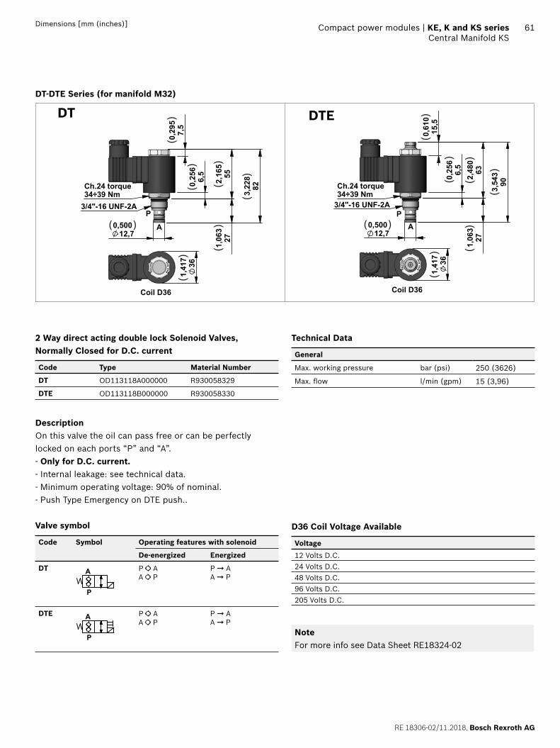
RE 18306-02/11.2018, Bosch Rexroth AG
Compact power modules | KE, K and KS series Central Manifold KS
61Dimensions [mm (inches)]
DT-DTE Series (for manifold M32)
0,50012,7
0,25
66,
5
1,
063
27
3,22
882
2,16
555
0,
295
7,5
Ch.24 torque34÷39 Nm
3/4"-16 UNF-2A
A
P
1,41
736
Coil D36
( )(
)
()
()
()
()
()
DT
0,50012,7
1,
063
27
2,4
80 63
0,25
66,
5
0,
610
15,5
3,
543
90
Ch.24 torque34÷39 Nm
3/4"-16 UNF-2A
AP
1,41
736
Coil D36
( )
()
()
()
()
()
()DTE
2 Way direct acting double lock Solenoid Valves, Normally Closed for D.C. current
Code Type Material Number
DT OD113118A000000 R930058329
DTE OD113118B000000 R930058330
DescriptionOn this valve the oil can pass free or can be perfectly locked on each ports “P” and “A”.- Only for D.C. current.- Internal leakage: see technical data.- Minimum operating voltage: 90% of nominal.- Push Type Emergency on DTE push..
Valve symbol
Code Symbol Operating features with solenoid
De-energized Energized
DT
P
A P AA P
P ➞ AA ➞ P
DTE
P
A P AA P
P ➞ AA ➞ P
Technical Data
General
Max. working pressure bar (psi) 250 (3626)
Max. fl ow l/min (gpm) 15 (3,96)
D36 Coil Voltage Available
Voltage
12 Volts D.C.
24 Volts D.C.
48 Volts D.C.
96 Volts D.C.
205 Volts D.C.
NoteFor more info see Data Sheet RE18324-02
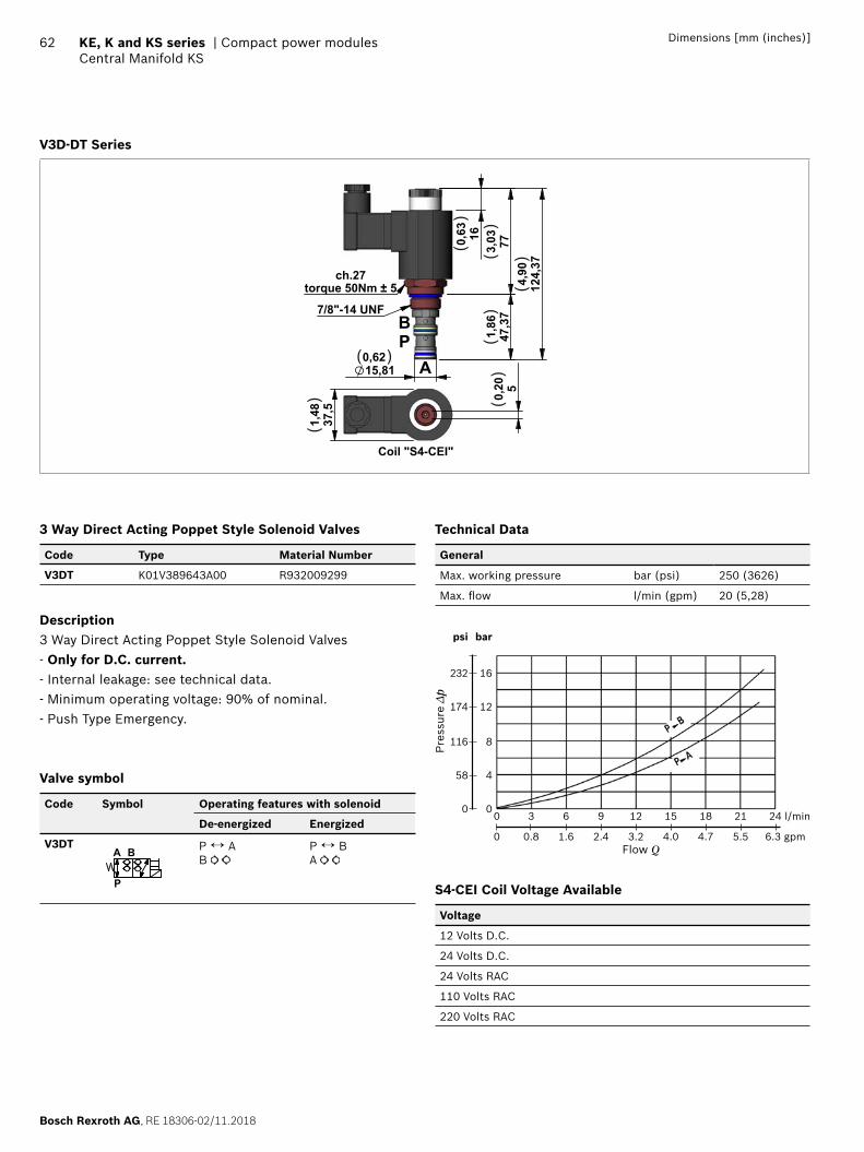
Bosch Rexroth AG, RE 18306-02/11.2018
62 KE, K and KS series | Compact power modulesCentral Manifold KS
Dimensions [mm (inches)]
V3D-DT Series
160,63
773,03
47,3
71,
86
124,
374,
90
15,810,62
ch.27torque 50Nm ± 5
7/8"-14 UNF37
,51,
48
50,20
Coil "S4-CEI"
APB
( )
()
()
()
()
()
()
3 Way Direct Acting Poppet Style Solenoid Valves
Code Type Material Number
V3DT K01V389643A00 R932009299
Description3 Way Direct Acting Poppet Style Solenoid Valves- Only for D.C. current.- Internal leakage: see technical data.- Minimum operating voltage: 90% of nominal.- Push Type Emergency.
Valve symbol
Code Symbol Operating features with solenoid
De-energized Energized
V3DT
P
A B P ↔ AB
P ↔ BA
Technical Data
General
Max. working pressure bar (psi) 250 (3626)
Max. fl ow l/min (gpm) 20 (5,28)
bar
16
12
8
4
0
psi
232
174
116
58
0
Pre
ssur
e Δp
0 3 6 9 12 15 18 21 24 l/min
0 0.8 1.6 2.4 3.2 4.0 4.7 5.5 6.3 gpmFlow Q
S4-CEI Coil Voltage Available
Voltage
12 Volts D.C.
24 Volts D.C.
24 Volts RAC
110 Volts RAC
220 Volts RAC
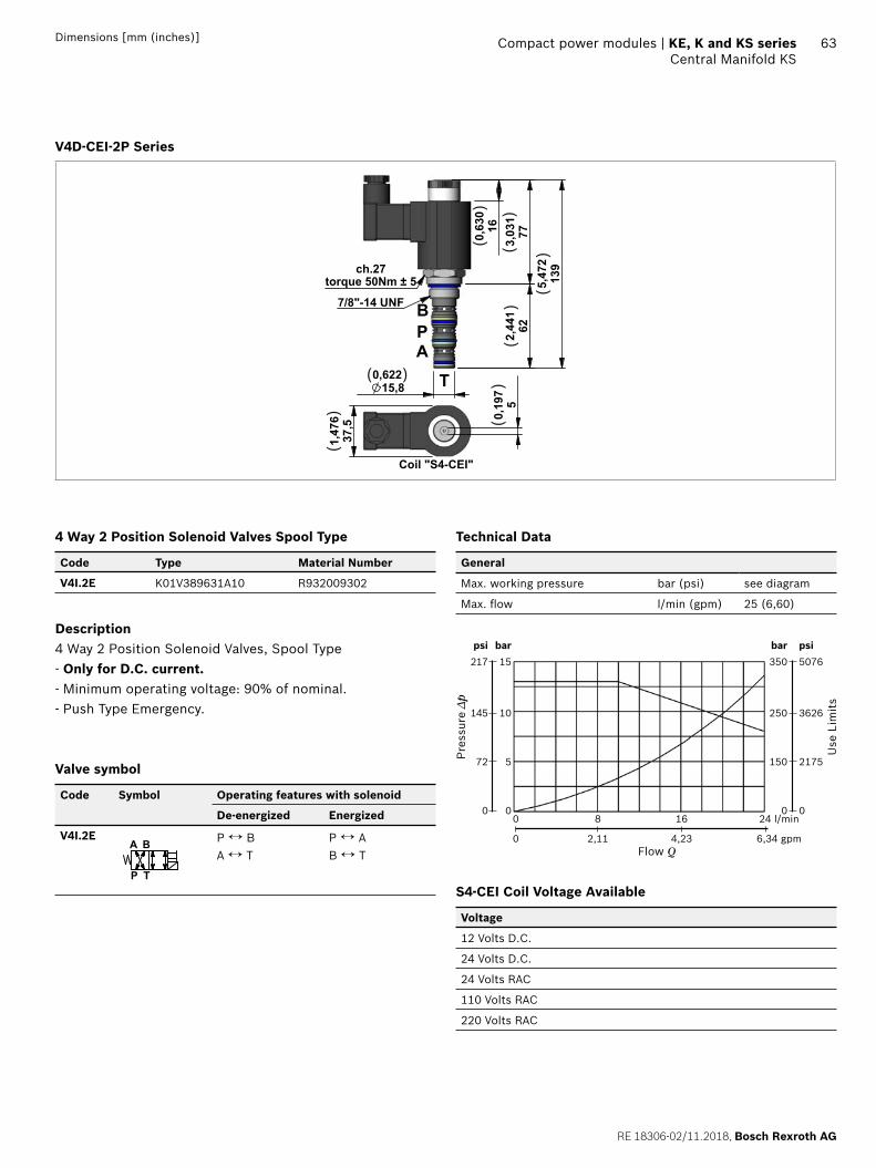
RE 18306-02/11.2018, Bosch Rexroth AG
Compact power modules | KE, K and KS series Central Manifold KS
63Dimensions [mm (inches)]
V4D-CEI-2P Series
160,63
0
773,03
1622,44
1
139
5,47
2
15,80,622
ch.27torque 50Nm ± 5
7/8"-14 UNF B
T
AP
37,5
1,47
6
50,
197
Coil "S4-CEI"
( )
()
()
()
()
()
()
4 Way 2 Position Solenoid Valves Spool Type
Code Type Material Number
V4I.2E K01V389631A10 R932009302
Description4 Way 2 Position Solenoid Valves, Spool Type- Only for D.C. current.- Minimum operating voltage: 90% of nominal.- Push Type Emergency.
Valve symbol
Code Symbol Operating features with solenoid
De-energized Energized
V4I.2E
P
A B
T
P ↔ BA ↔ T
P ↔ AB ↔ T
Technical Data
General
Max. working pressure bar (psi) see diagram
Max. fl ow l/min (gpm) 25 (6,60)
bar
15
10
5
0
bar
350
250
150
00 8 16 24 l/min
0 2,11 4,23 6,34 gpm
psi
217
145
72
0
psi
5076
3626
2175
0
Pre
ssur
e Δp
Use
Lim
its
Flow Q
S4-CEI Coil Voltage Available
Voltage
12 Volts D.C.
24 Volts D.C.
24 Volts RAC
110 Volts RAC
220 Volts RAC
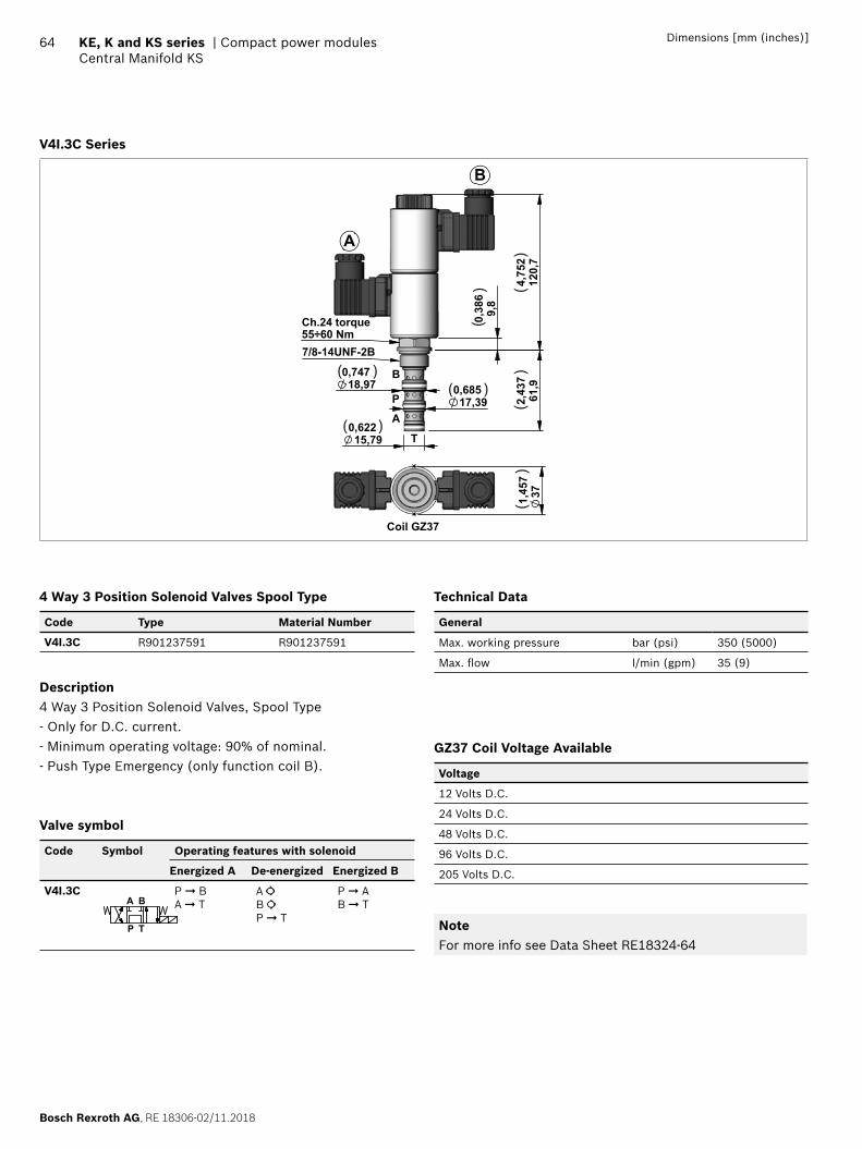
Bosch Rexroth AG, RE 18306-02/11.2018
64 KE, K and KS series | Compact power modulesCentral Manifold KS
Dimensions [mm (inches)]
V4I.3C Series
0,62215,79
0,68517,39
0,74718,97
2,43
761
,9
0,
386
9,8
4,75
212
0,7
Ch.24 torque
7/8-14UNF-2B55÷60 Nm
T
A
P
B
A
B
1,45
737
Coil GZ37
( )
() (
)(
)(
)
( )
( )
4 Way 3 Position Solenoid Valves Spool Type
Code Type Material Number
V4I.3C R901237591 R901237591
Description4 Way 3 Position Solenoid Valves, Spool Type- Only for D.C. current.- Minimum operating voltage: 90% of nominal.- Push Type Emergency (only function coil B).
Valve symbol
Code Symbol Operating features with solenoid
Energized A De-energized Energized B
V4I.3C
P
A B
T
P ➞ BA ➞ T
A
B
P ➞ T
P ➞ AB ➞ T
Technical Data
General
Max. working pressure bar (psi) 350 (5000)
Max. fl ow l/min (gpm) 35 (9)
GZ37 Coil Voltage Available
Voltage
12 Volts D.C.
24 Volts D.C.
48 Volts D.C.
96 Volts D.C.
205 Volts D.C.
NoteFor more info see Data Sheet RE18324-64
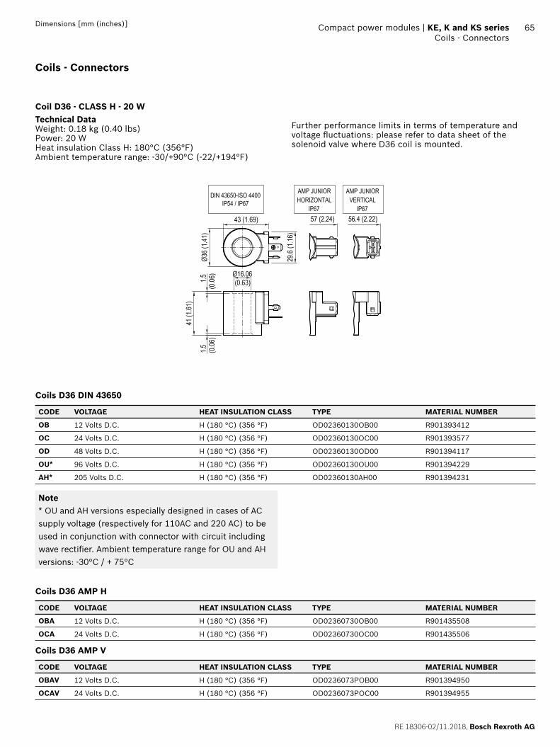
RE 18306-02/11.2018, Bosch Rexroth AG
Compact power modules | KE, K and KS series Coils - Connectors
65Dimensions [mm (inches)]
Coils - Connectors
Coil D36 - CLASS H - 20 WTechnical DataWeight: 0.18 kg (0.40 lbs)Power: 20 WHeat insulation Class H: 180°C (356°F)Ambient temperature range: -30/+90°C (-22/+194°F)
Further performance limits in terms of temperature and voltage fl uctuations: please refer to data sheet of the solenoid valve where D36 coil is mounted.
Coils D36 DIN 43650
CODE VOLTAGE HEAT INSULATION CLASS TYPE MATERIAL NUMBER
OB 12 Volts D.C. H (180 °C) (356 °F) OD02360130OB00 R901393412
OC 24 Volts D.C. H (180 °C) (356 °F) OD02360130OC00 R901393577
OD 48 Volts D.C. H (180 °C) (356 °F) OD02360130OD00 R901394117
OU* 96 Volts D.C. H (180 °C) (356 °F) OD02360130OU00 R901394229
AH* 205 Volts D.C. H (180 °C) (356 °F) OD02360130AH00 R901394231
Note* OU and AH versions especially designed in cases of AC supply voltage (respectively for 110AC and 220 AC) to be used in conjunction with connector with circuit including wave rectifi er. Ambient temperature range for OU and AH versions: -30°C / + 75°C
Coils D36 AMP H
CODE VOLTAGE HEAT INSULATION CLASS TYPE MATERIAL NUMBER
OBA 12 Volts D.C. H (180 °C) (356 °F) OD02360730OB00 R901435508
OCA 24 Volts D.C. H (180 °C) (356 °F) OD02360730OC00 R901435506
Coils D36 AMP V
CODE VOLTAGE HEAT INSULATION CLASS TYPE MATERIAL NUMBER
OBAV 12 Volts D.C. H (180 °C) (356 °F) OD0236073POB00 R901394950
OCAV 24 Volts D.C. H (180 °C) (356 °F) OD0236073POC00 R901394955
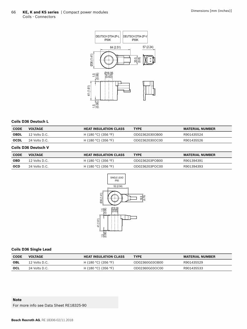
Bosch Rexroth AG, RE 18306-02/11.2018
66 KE, K and KS series | Compact power modulesCoils - Connectors
Dimensions [mm (inches)]
Coils D36 Deutsch L
CODE VOLTAGE HEAT INSULATION CLASS TYPE MATERIAL NUMBER
OBDL 12 Volts D.C. H (180 °C) (356 °F) OD02362030OB00 R901435524
OCDL 24 Volts D.C. H (180 °C) (356 °F) OD02362030OC00 R901435526
Coils D36 Deutsch V
CODE VOLTAGE HEAT INSULATION CLASS TYPE MATERIAL NUMBER
OBD 12 Volts D.C. H (180 °C) (356 °F) OD0236203POB00 R901394391
OCD 24 Volts D.C. H (180 °C) (356 °F) OD0236203POC00 R901394393
Coils D36 Single Lead
CODE VOLTAGE HEAT INSULATION CLASS TYPE MATERIAL NUMBER
OBL 12 Volts D.C. H (180 °C) (356 °F) OD02360G03OB00 R901435529
OCL 24 Volts D.C. H (180 °C) (356 °F) OD02360G03OC00 R901435533
NoteFor more info see Data Sheet RE18325-90
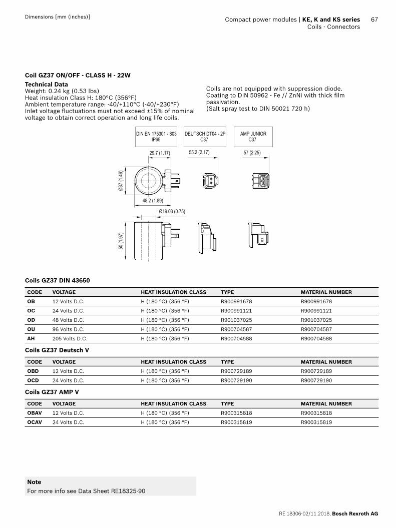
RE 18306-02/11.2018, Bosch Rexroth AG
Compact power modules | KE, K and KS series Coils - Connectors
67Dimensions [mm (inches)]
Coil GZ37 ON/OFF - CLASS H - 22WTechnical DataWeight: 0.24 kg (0.53 lbs)Heat insulation Class H: 180°C (356°F)Ambient temperature range: -40/+110°C (-40/+230°F)Inlet voltage fl uctuations must not exceed ±15% of nominal voltage to obtain correct operation and long life coils.
Coils are not equipped with suppression diode.Coating to DIN 50962 - Fe // ZnNi with thick fi lm passivation.(Salt spray test to DIN 50021 720 h)
Coils GZ37 DIN 43650
CODE VOLTAGE HEAT INSULATION CLASS TYPE MATERIAL NUMBER
OB 12 Volts D.C. H (180 °C) (356 °F) R900991678 R900991678
OC 24 Volts D.C. H (180 °C) (356 °F) R900991121 R900991121
OD 48 Volts D.C. H (180 °C) (356 °F) R901037025 R901037025
OU 96 Volts D.C. H (180 °C) (356 °F) R900704587 R900704587
AH 205 Volts D.C. H (180 °C) (356 °F) R900704588 R900704588
Coils GZ37 Deutsch V
CODE VOLTAGE HEAT INSULATION CLASS TYPE MATERIAL NUMBER
OBD 12 Volts D.C. H (180 °C) (356 °F) R900729189 R900729189
OCD 24 Volts D.C. H (180 °C) (356 °F) R900729190 R900729190
Coils GZ37 AMP V
CODE VOLTAGE HEAT INSULATION CLASS TYPE MATERIAL NUMBER
OBAV 12 Volts D.C. H (180 °C) (356 °F) R900315818 R900315818
OCAV 24 Volts D.C. H (180 °C) (356 °F) R900315819 R900315819
NoteFor more info see Data Sheet RE18325-90
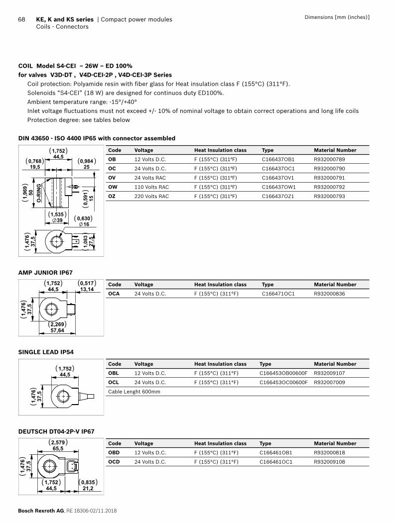
Bosch Rexroth AG, RE 18306-02/11.2018
68 KE, K and KS series | Compact power modulesCoils - Connectors
Dimensions [mm (inches)]
COIL Model S4-CEI – 26W – ED 100% for valves V3D-DT , V4D-CEI-2P , V4D-CEI-3P Series Coil protection: Polyamide resin with fi ber glass for Heat insulation class F (155°C) (311°F). Solenoids “S4-CEI” (18 W) are designed for continuos duty ED100%. Ambient temperature range: -15°/+40° Inlet voltage fl uctuations must not exceed +/- 10% of nominal voltage to obtain correct operations and long life coils Protection degree: see tables below
DIN 43650 - ISO 4400 IP65 with connector assembled
501,969
150,591
19,50,768
250,984
44,51,752
391,535
O-RING
37,5
1,476
160,630
27,5
1,083
( )( )
( ) ( )
( )
()
()
()
()
Code Voltage Heat Insulation class Type Material Number
OB 12 Volts D.C. F (155°C) (311°F) C166437OB1 R932000789
OC 24 Volts D.C. F (155°C) (311°F) C166437OC1 R932000790
OV 24 Volts RAC F (155°C) (311°F) C166437OV1 R932000791
OW 110 Volts RAC F (155°C) (311°F) C166437OW1 R932000792
OZ 220 Volts RAC F (155°C) (311°F) C166437OZ1 R932000793
AMP JUNIOR IP67
37,5
1,476
44,51,752
13,140,517
57,642,269
( )
( )
( )
()
Code Voltage Heat Insulation class Type Material Number
OCA 24 Volts D.C. F (155°C) (311°F) C166471OC1 R932000836
SINGLE LEAD IP54
44,51,752
37,5
1,476
( )
()
Code Voltage Heat Insulation class Type Material Number
OBL 12 Volts D.C. F (155°C) (311°F) C166453OB00600F R932009107
OCL 24 Volts D.C. F (155°C) (311°F) C166453OC00600F R932007009
Cable Lenght 600mm
DEUTSCH DT04-2P-V IP67
37,5
1,476
44,51,752
21,20,835
65,52,579( )
( ) ( )
()
Code Voltage Heat Insulation class Type Material Number
OBD 12 Volts D.C. F (155°C) (311°F) C166461OB1 R932000818
OCD 24 Volts D.C. F (155°C) (311°F) C166461OC1 R932009108
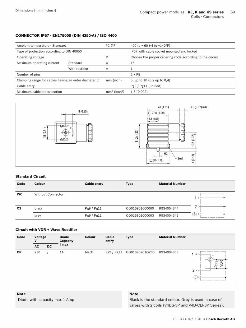
RE 18306-02/11.2018, Bosch Rexroth AG
Compact power modules | KE, K and KS series Coils - Connectors
69Dimensions [mm (inches)]
CONNECTOR IP67 - EN175000 (DIN 4350-A) / ISO 4400
Ambient temperature - Standard °C (°F) - 20 to + 60 (-4 to +140°F)
Type of protection according to DIN 40050 IP67 with cable socket mounted and locked
Operating voltage V Choose the proper ordering code according to the circuit
Maximum operating current Standard A 16
With rectifi er A 1
Number of pins 2 + PE
Clamping range for cables having an outer diameter of mm (inch) 5, up to 10 (0,2 up to 0,4)
Cable entry Pg9 / Pg11 (unifi ed)
Maximum cable cross-section mm2 (inch2) 1.5 (0,002)
Standard Circuit
Code Colour Cable entry Type Material Number
WC Without Connector
CS black Pg9 / Pg11 OD016901000000 R934004344
grey Pg9 / Pg11 OD016901000003 R934004346
Circuit with VDR + Wave Rectifi er
Code VoltageV
DiodeCapacityI max
Colour Cable entry
Type Material Number
AC DC
CR 230 / 1A black Pg9 / Pg11 OD01690201OZ00 R934004353
Note Diode with capacity max 1 Amp.
NoteBlack is the standard colour. Grey is used in case of valves with 2 coils (V4DS-3P and V4D-CEI-3P Series).
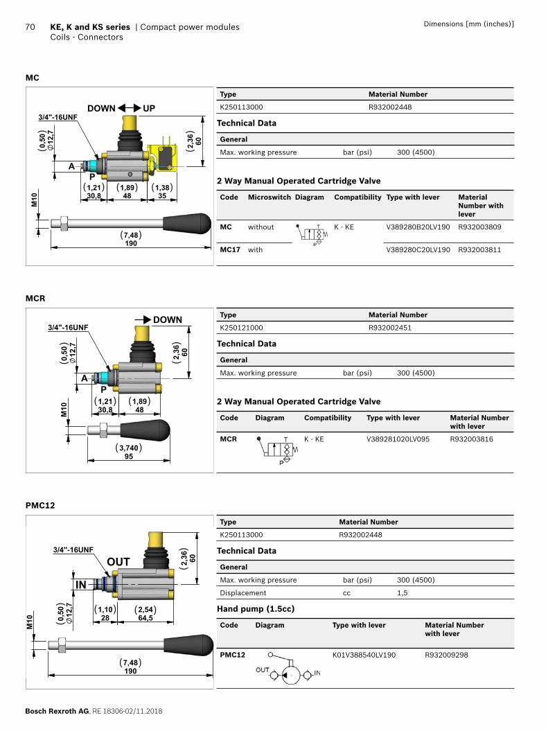
Bosch Rexroth AG, RE 18306-02/11.2018
70 KE, K and KS series | Compact power modulesCoils - Connectors
Dimensions [mm (inches)]
MC
602,36
351,38
481,89
30,81,21
12,7
0,50
1907,48
M10
3/4"-16UNF
PA
DOWN UP
( ) ( ) ( )
( )
()
()
Type Material Number
K250113000 R932002448
Technical Data
General
Max. working pressure bar (psi) 300 (4500)
2 Way Manual Operated Cartridge Valve
Code Microswitch Diagram Compatibility Type with lever Material Number with lever
MC without K - KE V389280B20LV190 R932003809
MC17 with V389280C20LV190 R932003811
MCR
12,7
0,50
M10 48
1,8930,81,21
602,36
953,740
3/4"-16UNF
PA
DOWN
( ) ( )
( )
()
()
Type Material Number
K250121000 R932002451
Technical Data
General
Max. working pressure bar (psi) 300 (4500)
2 Way Manual Operated Cartridge Valve
Code Diagram Compatibility Type with lever Material Number with lever
MCR K - KE V389281020LV095 R932003816
PMC12
M10
1907,48
64,52,54
281,10
602,36
12,7
0,50
3/4"-16UNF
OUT
IN
( )( )
( )
()
()
Type Material Number
K250113000 R932002448
Technical Data
General
Max. working pressure bar (psi) 300 (4500)
Displacement cc 1,5
Hand pump (1.5cc)
Code Diagram Type with lever Material Number with lever
PMC12 K01V388540LV190 R932009298
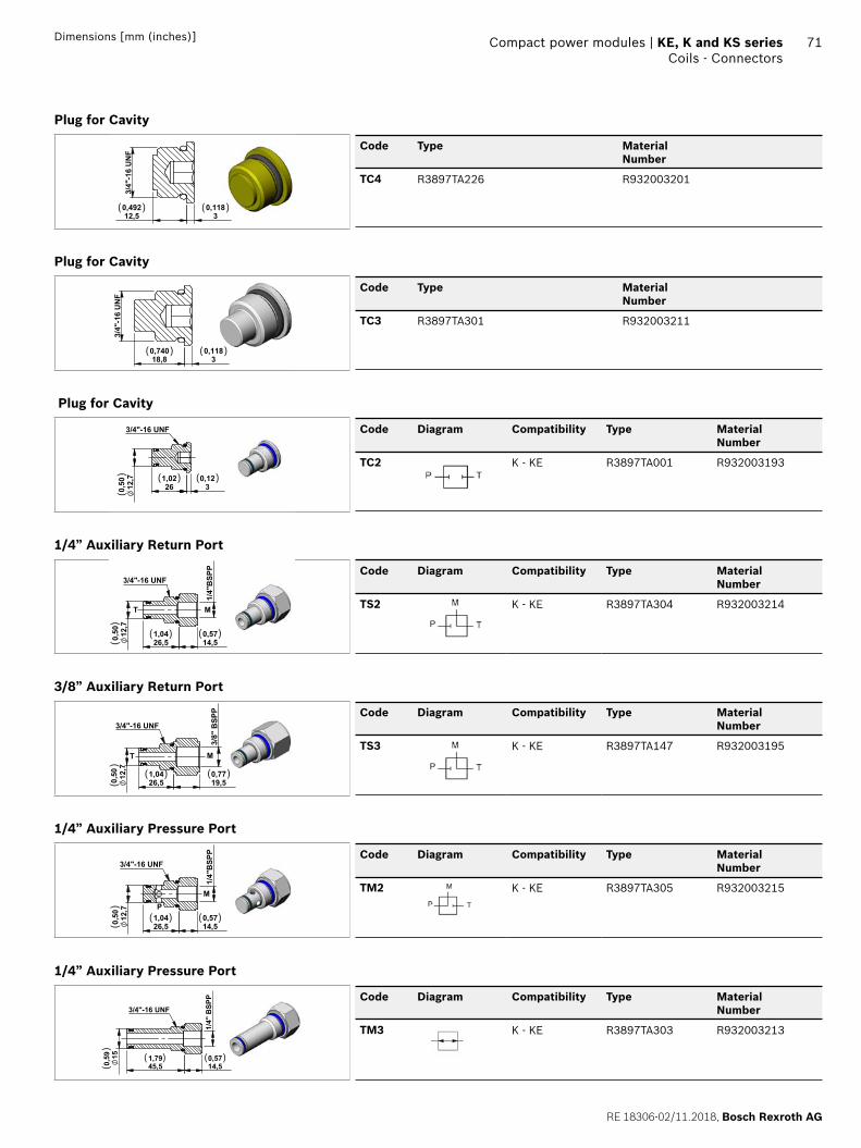
RE 18306-02/11.2018, Bosch Rexroth AG
Compact power modules | KE, K and KS series Coils - Connectors
71Dimensions [mm (inches)]
Plug for Cavity 3
/4"-
16 U
NF
0,118
3 0,49212,5
( ) ( )
Code Type MaterialNumber
TC4 R3897TA226 R932003201
Plug for Cavity
0,118
3 0,74018,8
3/4
"-16
UN
F
( ) ( )
Code Type MaterialNumber
TC3 R3897TA301 R932003211
Plug for Cavity
12,7
0,50 3
0,1226
1,02
3/4"-16 UNF
( ) ( )
()
Code Diagram Compatibility Type MaterialNumber
TC2 K - KE R3897TA001 R932003193
1/4” Auxiliary Return Port
14,50,57
26,51,0412
,70,
50
1/4"
BSP
P
3/4"-16 UNF
MT
( )( )
()
Code Diagram Compatibility Type MaterialNumber
TS2 K - KE R3897TA304 R932003214
3/8” Auxiliary Return Port
M
19,50,77
26,51,0412
,70,
50
3/8"
BSP
P
3/4"-16 UNF
T
( )( )
()
Code Diagram Compatibility Type MaterialNumber
TS3 K - KE R3897TA147 R932003195
1/4” Auxiliary Pressure Port
14,50,5712
,70,
50
1/4"
BSP
P
26,51,04
3/4"-16 UNF
MP
( ) ( )
()
Code Diagram Compatibility Type MaterialNumber
TM2 K - KE R3897TA305 R932003215
1/4” Auxiliary Pressure Port
45,51,79
14,50,5715
0,59
1/4"
BSP
P
3/4"-16 UNF
( ) ( )
()
Code Diagram Compatibility Type MaterialNumber
TM3 K - KE R3897TA303 R932003213
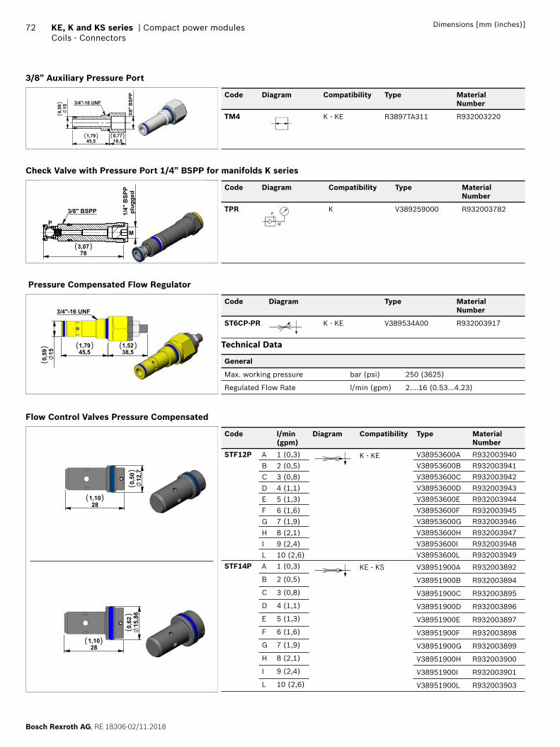
Bosch Rexroth AG, RE 18306-02/11.2018
72 KE, K and KS series | Compact power modulesCoils - Connectors
Dimensions [mm (inches)]
3/8” Auxiliary Pressure Port
19,50,77
45,51,79
150,
59
3/8"
BSP
P
3/4"-16 UNF
( ) ( )
()
Code Diagram Compatibility Type MaterialNumber
TM4 K - KE R3897TA311 R932003220
Check Valve with Pressure Port 1/4” BSPP for manifolds K series
783,07
plug
ged
1/4"
BSP
P
3/8" BSPP
MP
( )
Code Diagram Compatibility Type MaterialNumber
TPR K V389259000 R932003782
Pressure Compensated Flow Regulator
38,51,52
45,51,79
150,
59
3/4"-16 UNF
( ) ( )
()
Code Diagram Type MaterialNumber
ST6CP-PR K - KE V389534A00 R932003917
Technical Data
General
Max. working pressure bar (psi) 250 (3625)
Regulated Flow Rate l/min (gpm) 2....16 (0.53...4.23)
Flow Control Valves Pressure Compensated
281,10
15,86
0,62
( )
()
281,10
12,7
0,50
( )
()
Code l/min(gpm)
Diagram Compatibility Type MaterialNumber
STF12P A 1 (0,3) K - KE V38953600A R932003940
B 2 (0,5) V38953600B R932003941
C 3 (0,8) V38953600C R932003942
D 4 (1,1) V38953600D R932003943
E 5 (1,3) V38953600E R932003944
F 6 (1,6) V38953600F R932003945
G 7 (1,9) V38953600G R932003946
H 8 (2,1) V38953600H R932003947
I 9 (2,4) V38953600I R932003948
L 10 (2,6) V38953600L R932003949STF14P A 1 (0,3) KE - KS V38951900A R932003892
B 2 (0,5) V38951900B R932003894
C 3 (0,8) V38951900C R932003895
D 4 (1,1) V38951900D R932003896
E 5 (1,3) V38951900E R932003897
F 6 (1,6) V38951900F R932003898
G 7 (1,9) V38951900G R932003899
H 8 (2,1) V38951900H R932003900
I 9 (2,4) V38951900I R932003901
L 10 (2,6) V38951900L R932003903
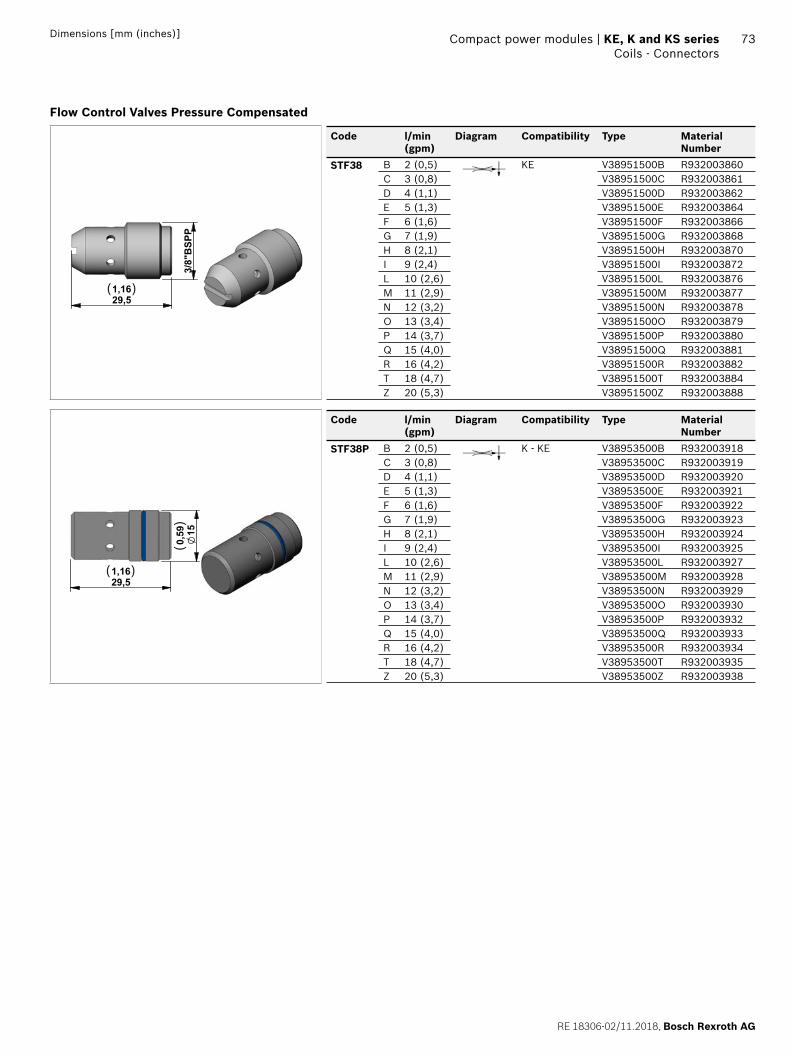
RE 18306-02/11.2018, Bosch Rexroth AG
Compact power modules | KE, K and KS series Coils - Connectors
73Dimensions [mm (inches)]
Flow Control Valves Pressure Compensated
29,51,16
3/8"BSPP
( )
Code l/min(gpm)
Diagram Compatibility Type MaterialNumber
STF38 B 2 (0,5) KE V38951500B R932003860C 3 (0,8) V38951500C R932003861D 4 (1,1) V38951500D R932003862E 5 (1,3) V38951500E R932003864F 6 (1,6) V38951500F R932003866G 7 (1,9) V38951500G R932003868H 8 (2,1) V38951500H R932003870I 9 (2,4) V38951500I R932003872L 10 (2,6) V38951500L R932003876M 11 (2,9) V38951500M R932003877N 12 (3,2) V38951500N R932003878O 13 (3,4) V38951500O R932003879P 14 (3,7) V38951500P R932003880Q 15 (4,0) V38951500Q R932003881R 16 (4,2) V38951500R R932003882T 18 (4,7) V38951500T R932003884Z 20 (5,3) V38951500Z R932003888
29,51,16
150,59
( )
()
Code l/min(gpm)
Diagram Compatibility Type MaterialNumber
STF38P B 2 (0,5) K - KE V38953500B R932003918C 3 (0,8) V38953500C R932003919D 4 (1,1) V38953500D R932003920E 5 (1,3) V38953500E R932003921F 6 (1,6) V38953500F R932003922G 7 (1,9) V38953500G R932003923H 8 (2,1) V38953500H R932003924I 9 (2,4) V38953500I R932003925L 10 (2,6) V38953500L R932003927M 11 (2,9) V38953500M R932003928N 12 (3,2) V38953500N R932003929O 13 (3,4) V38953500O R932003930P 14 (3,7) V38953500P R932003932Q 15 (4,0) V38953500Q R932003933R 16 (4,2) V38953500R R932003934T 18 (4,7) V38953500T R932003935Z 20 (5,3) V38953500Z R932003938
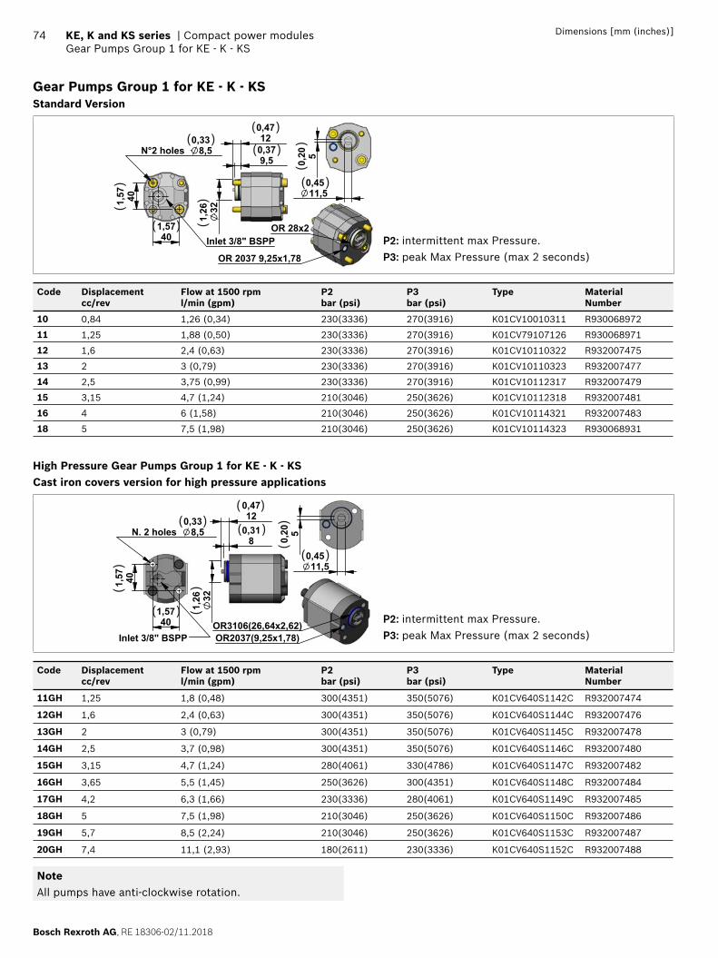
Bosch Rexroth AG, RE 18306-02/11.2018
74 KE, K and KS series | Compact power modulesGear Pumps Group 1 for KE - K - KS
Dimensions [mm (inches)]
Gear Pumps Group 1 for KE - K - KSStandard Version
401,57
401,57
N°2 holes 8,50,33
Inlet 3/8" BSPP
9,50,3712
0,47
321,
26
OR 2037 9,25x1,78
OR 28x2
50,20
11,50,45
( )( )
( )
( )
( )
()
()
()
P2: intermittent max Pressure.P3: peak Max Pressure (max 2 seconds)
Code Displacementcc/rev
Flow at 1500 rpml/min (gpm)
P2bar (psi)
P3bar (psi)
Type MaterialNumber
10 0,84 1,26 (0,34) 230(3336) 270(3916) K01CV10010311 R930068972
11 1,25 1,88 (0,50) 230(3336) 270(3916) K01CV79107126 R930068971
12 1,6 2,4 (0,63) 230(3336) 270(3916) K01CV10110322 R932007475
13 2 3 (0,79) 230(3336) 270(3916) K01CV10110323 R932007477
14 2,5 3,75 (0,99) 230(3336) 270(3916) K01CV10112317 R932007479
15 3,15 4,7 (1,24) 210(3046) 250(3626) K01CV10112318 R932007481
16 4 6 (1,58) 210(3046) 250(3626) K01CV10114321 R932007483
18 5 7,5 (1,98) 210(3046) 250(3626) K01CV10114323 R930068931
High Pressure Gear Pumps Group 1 for KE - K - KSCast iron covers version for high pressure applications
401,57
401,57
N. 2 holes 8,5 0,33
Inlet 3/8" BSPP
80,3112
0,47
321,
26
50,20
11,50,45
OR2037(9,25x1,78)OR3106(26,64x2,62)
( )( )
( )
( )
( )
()
()
()
P2: intermittent max Pressure.P3: peak Max Pressure (max 2 seconds)
Code Displacementcc/rev
Flow at 1500 rpml/min (gpm)
P2bar (psi)
P3bar (psi)
Type MaterialNumber
11GH 1,25 1,8 (0,48) 300(4351) 350(5076) K01CV640S1142C R932007474
12GH 1,6 2,4 (0,63) 300(4351) 350(5076) K01CV640S1144C R932007476
13GH 2 3 (0,79) 300(4351) 350(5076) K01CV640S1145C R932007478
14GH 2,5 3,7 (0,98) 300(4351) 350(5076) K01CV640S1146C R932007480
15GH 3,15 4,7 (1,24) 280(4061) 330(4786) K01CV640S1147C R932007482
16GH 3,65 5,5 (1,45) 250(3626) 300(4351) K01CV640S1148C R932007484
17GH 4,2 6,3 (1,66) 230(3336) 280(4061) K01CV640S1149C R932007485
18GH 5 7,5 (1,98) 210(3046) 250(3626) K01CV640S1150C R932007486
19GH 5,7 8,5 (2,24) 210(3046) 250(3626) K01CV640S1153C R932007487
20GH 7,4 11,1 (2,93) 180(2611) 230(3336) K01CV640S1152C R932007488
NoteAll pumps have anti-clockwise rotation.
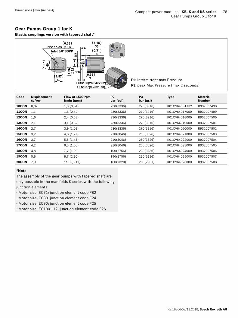
RE 18306-02/11.2018, Bosch Rexroth AG
Compact power modules | KE, K and KS series Gear Pumps Group 1 for K
75Dimensions [mm (inches)]
Gear Pumps Group 1 for KElastic couplings version with tapered shaft*
80,3130
1,18
321,
26
M7
90,35
1:8
401,57
401,57
N°2 holes 8,50,33
Inlet 3/8"BSPP
OR2037(9,25x1,78)OR3106(26,64x2,62)
( ) ( )
( )
( )( )
()
()
P2: intermittent max Pressure.P3: peak Max Pressure (max 2 seconds)
Code Displacementcc/rev
Flow at 1500 rpml/min (gpm)
P2bar (psi)
P3bar (psi)
Type MaterialNumber
10CON 0,82 1,3 (0,34) 230(3336) 270(3916) K01CV640S1132 R932007498
11CON 1,1 1,6 (0,42) 230(3336) 270(3916) K01CV64017000 R932007499
12CON 1,6 2,4 (0,63) 230(3336) 270(3916) K01CV64018000 R932007500
13CON 2,1 3,1 (0,82) 230(3336) 270(3916) K01CV64019000 R932007501
14CON 2,7 3,9 (1,03) 230(3336) 270(3916) K01CV64020000 R932007502
15CON 3,2 4,8 (1,27) 210(3046) 250(3626) K01CV64021000 R932007503
16CON 3,7 5,5 (1,45) 210(3046) 250(3626) K01CV64022000 R932007504
17CON 4,2 6,3 (1,66) 210(3046) 250(3626) K01CV64023000 R932007505
18CON 4,8 7,2 (1,90) 190(2756) 230(3336) K01CV64024000 R932007506
19CON 5,8 8,7 (2,30) 190(2756) 230(3336) K01CV64025000 R932007507
20CON 7,9 11,8 (3,12) 160(2320) 200(2901) K01CV64026000 R932007508
*NoteThe assembly of the gear pumps with tapered shaft are only possible in the manifolds K series with the following junction elements:- Motor size IEC71: junction element code F82- Motor size IEC80: junction element code F24- Motor size IEC90: junction element code F25- Motor size IEC100-112: junction element code F26
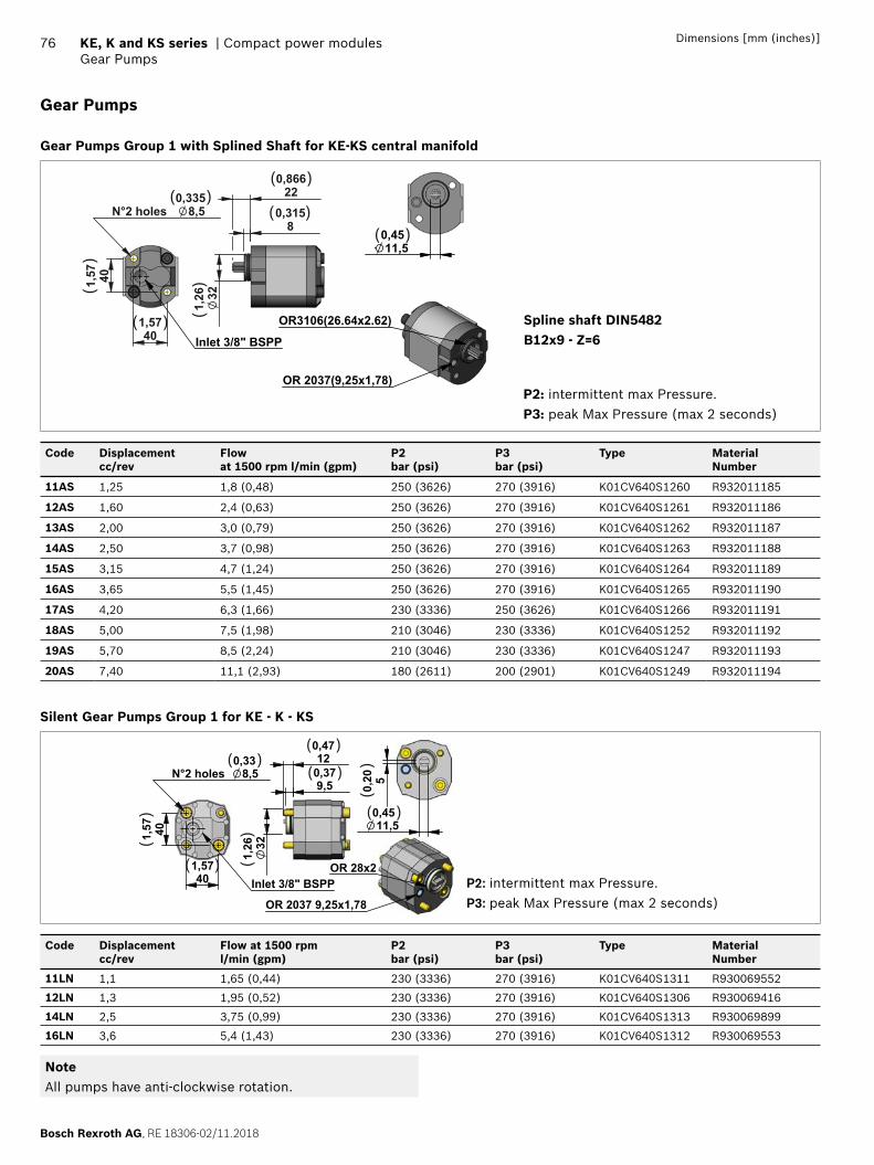
Bosch Rexroth AG, RE 18306-02/11.2018
76 KE, K and KS series | Compact power modulesGear Pumps
Dimensions [mm (inches)]
Gear Pumps
Gear Pumps Group 1 with Splined Shaft for KE-KS central manifold
401,57
401,57
N°2 holes 8,50,335
Inlet 3/8" BSPP
321,
26
80,315
220,866
OR 2037(9,25x1,78)
OR3106(26.64x2.62)
11,50,45
( )( )
( )( )
( )
()
()
P2: intermittent max Pressure.P3: peak Max Pressure (max 2 seconds)
Spline shaft DIN5482 B12x9 - Z=6
Code Displacementcc/rev
Flow at 1500 rpm l/min (gpm)
P2bar (psi)
P3bar (psi)
Type MaterialNumber
11AS 1,25 1,8 (0,48) 250 (3626) 270 (3916) K01CV640S1260 R932011185
12AS 1,60 2,4 (0,63) 250 (3626) 270 (3916) K01CV640S1261 R932011186
13AS 2,00 3,0 (0,79) 250 (3626) 270 (3916) K01CV640S1262 R932011187
14AS 2,50 3,7 (0,98) 250 (3626) 270 (3916) K01CV640S1263 R932011188
15AS 3,15 4,7 (1,24) 250 (3626) 270 (3916) K01CV640S1264 R932011189
16AS 3,65 5,5 (1,45) 250 (3626) 270 (3916) K01CV640S1265 R932011190
17AS 4,20 6,3 (1,66) 230 (3336) 250 (3626) K01CV640S1266 R932011191
18AS 5,00 7,5 (1,98) 210 (3046) 230 (3336) K01CV640S1252 R932011192
19AS 5,70 8,5 (2,24) 210 (3046) 230 (3336) K01CV640S1247 R932011193
20AS 7,40 11,1 (2,93) 180 (2611) 200 (2901) K01CV640S1249 R932011194
Silent Gear Pumps Group 1 for KE - K - KS
401,57
401,57
N°2 holes 8,50,33
Inlet 3/8" BSPP
9,50,3712
0,47
321,
26
OR 2037 9,25x1,78
OR 28x2
50,20
11,50,45
( )( )
( )
( )
( )
()
()
()
P2: intermittent max Pressure.P3: peak Max Pressure (max 2 seconds)
Code Displacementcc/rev
Flow at 1500 rpml/min (gpm)
P2bar (psi)
P3bar (psi)
Type MaterialNumber
11LN 1,1 1,65 (0,44) 230 (3336) 270 (3916) K01CV640S1311 R930069552
12LN 1,3 1,95 (0,52) 230 (3336) 270 (3916) K01CV640S1306 R930069416
14LN 2,5 3,75 (0,99) 230 (3336) 270 (3916) K01CV640S1313 R930069899
16LN 3,6 5,4 (1,43) 230 (3336) 270 (3916) K01CV640S1312 R930069553
NoteAll pumps have anti-clockwise rotation.
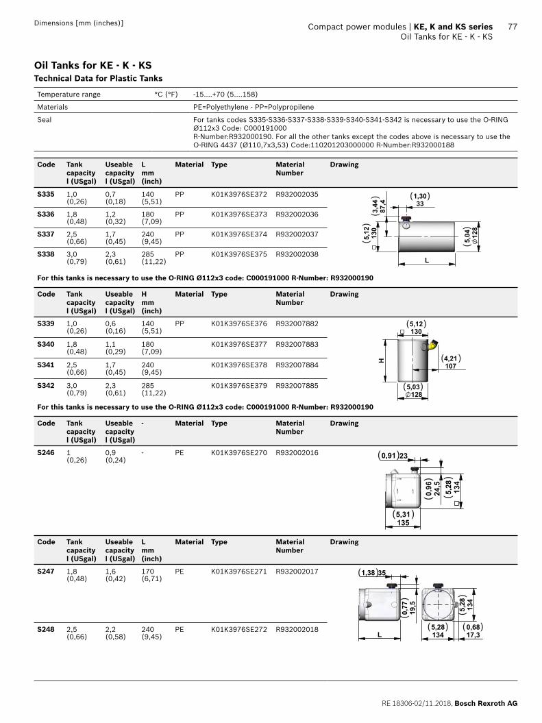
RE 18306-02/11.2018, Bosch Rexroth AG
Compact power modules | KE, K and KS series Oil Tanks for KE - K - KS
77Dimensions [mm (inches)]
Oil Tanks for KE - K - KSTechnical Data for Plastic Tanks
Temperature range °C (°F) -15....+70 (5....158)
Materials PE=Polyethylene - PP=Polypropilene
Seal For tanks codes S335-S336-S337-S338-S339-S340-S341-S342 is necessary to use the O-RING Ø112x3 Code: C000191000 R-Number:R932000190. For all the other tanks except the codes above is necessary to use the O-RING 4437 (Ø110,7x3,53) Code:110201203000000 R-Number:R932000188
Code Tank capacityl (USgal)
Useable capacityl (USgal)
Lmm(inch)
Material Type MaterialNumber
Drawing
S335 1,0(0,26)
0,7(0,18)
140(5,51)
PP K01K3976SE372 R932002035
L
331,30
87,4
3,44
128
5,04130
5,12
( )
()
()
()
S336 1,8(0,48)
1,2(0,32)
180(7,09)
PP K01K3976SE373 R932002036
S337 2,5(0,66)
1,7(0,45)
240(9,45)
PP K01K3976SE374 R932002037
S338 3,0(0,79)
2,3(0,61)
285(11,22)
PP K01K3976SE375 R932002038
For this tanks is necessary to use the O-RING Ø112x3 code: C000191000 R-Number: R932000190
Code Tank capacityl (USgal)
Useable capacityl (USgal)
Hmm(inch)
Material Type MaterialNumber
Drawing
S339 1,0(0,26)
0,6(0,16)
140(5,51)
PP K01K3976SE376 R932007882
1285,03
H
1305,12
1074,21
( )
( )
( )
S340 1,8(0,48)
1,1(0,29)
180(7,09)
K01K3976SE377 R932007883
S341 2,5(0,66)
1,7(0,45)
240(9,45)
K01K3976SE378 R932007884
S342 3,0(0,79)
2,3(0,61)
285(11,22)
K01K3976SE379 R932007885
For this tanks is necessary to use the O-RING Ø112x3 code: C000191000 R-Number: R932000190
Code Tank capacityl (USgal)
Useable capacityl (USgal)
- Material Type MaterialNumber
Drawing
S246 1(0,26)
0,9(0,24)
- PE K01K3976SE270 R932002016
1355,31
134
5,28
230,91
24,5
0,96
( )
( )
()
()
Code Tank capacityl (USgal)
Useable capacityl (USgal)
Lmm(inch)
Material Type MaterialNumber
Drawing
S247 1,8(0,48)
1,6(0,42)
170(6,71)
PE K01K3976SE271 R932002017
L
351,38
19,5
0,77
1345,28
134
5,28
17,30,68
( )
( ) ( )
()
()
S248 2,5(0,66)
2,2(0,58)
240(9,45)
PE K01K3976SE272 R932002018
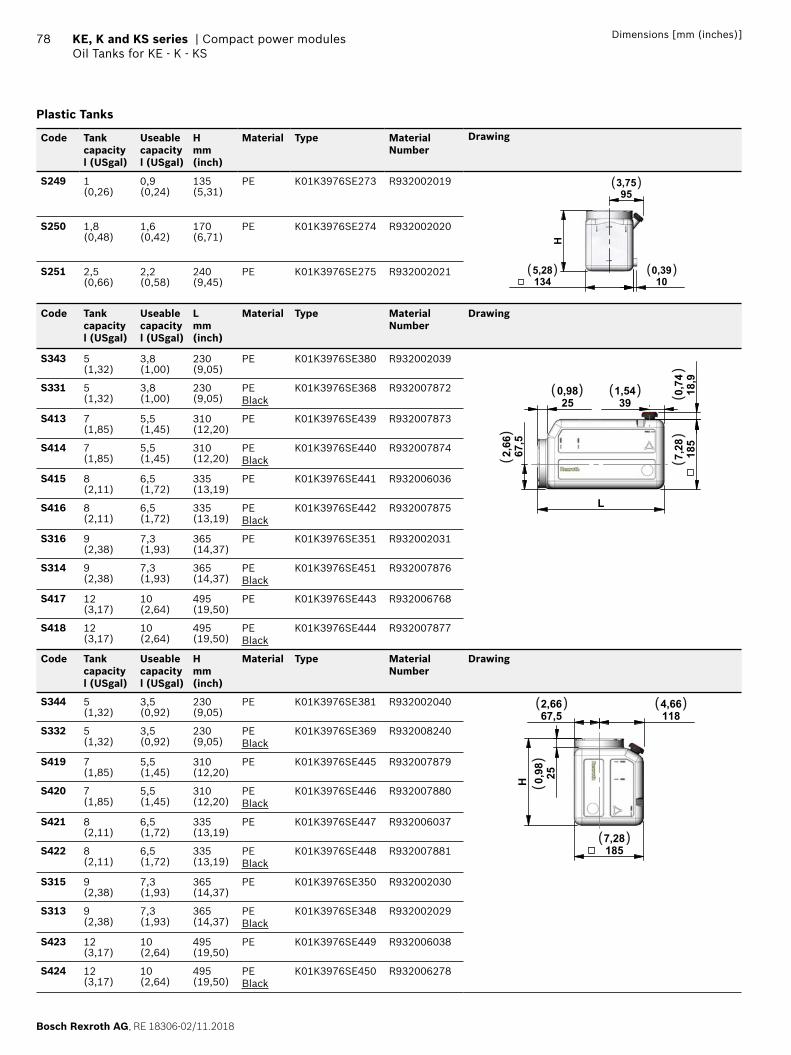
Bosch Rexroth AG, RE 18306-02/11.2018
78 KE, K and KS series | Compact power modulesOil Tanks for KE - K - KS
Dimensions [mm (inches)]
Plastic Tanks
Code Tank capacityl (USgal)
Useable capacityl (USgal)
H mm(inch)
Material Type MaterialNumber
Drawing
S249 1(0,26)
0,9(0,24)
135(5,31)
PE K01K3976SE273 R932002019
H
100,39
953,75
1345,28
( )
( )( )
S250 1,8(0,48)
1,6(0,42)
170(6,71)
PE K01K3976SE274 R932002020
S251 2,5(0,66)
2,2(0,58)
240(9,45)
PE K01K3976SE275 R932002021
Code Tank capacityl (USgal)
Useable capacityl (USgal)
L mm(inch)
Material Type MaterialNumber
Drawing
S343 5(1,32)
3,8(1,00)
230(9,05)
PE K01K3976SE380 R932002039
L
185
7,28
250,98
391,54
67,5
2,66
18,9
0,74( ) ( )
()
()
()
S331 5(1,32)
3,8(1,00)
230(9,05)
PEBlack
K01K3976SE368 R932007872
S413 7(1,85)
5,5(1,45)
310(12,20)
PE K01K3976SE439 R932007873
S414 7(1,85)
5,5(1,45)
310(12,20)
PEBlack
K01K3976SE440 R932007874
S415 8(2,11)
6,5(1,72)
335(13,19)
PE K01K3976SE441 R932006036
S416 8(2,11)
6,5(1,72)
335(13,19)
PEBlack
K01K3976SE442 R932007875
S316 9(2,38)
7,3(1,93)
365(14,37)
PE K01K3976SE351 R932002031
S314 9(2,38)
7,3(1,93)
365(14,37)
PEBlack
K01K3976SE451 R932007876
S417 12(3,17)
10(2,64)
495(19,50)
PE K01K3976SE443 R932006768
S418 12(3,17)
10(2,64)
495(19,50)
PEBlack
K01K3976SE444 R932007877
Code Tank capacityl (USgal)
Useable capacityl (USgal)
Hmm(inch)
Material Type MaterialNumber
Drawing
S344 5(1,32)
3,5(0,92)
230(9,05)
PE K01K3976SE381 R932002040
H 250,98
67,52,66
1184,66
1857,28
( ) ( )
( )
()
S332 5(1,32)
3,5(0,92)
230(9,05)
PEBlack
K01K3976SE369 R932008240
S419 7(1,85)
5,5(1,45)
310(12,20)
PE K01K3976SE445 R932007879
S420 7(1,85)
5,5(1,45)
310(12,20)
PEBlack
K01K3976SE446 R932007880
S421 8(2,11)
6,5(1,72)
335(13,19)
PE K01K3976SE447 R932006037
S422 8(2,11)
6,5(1,72)
335(13,19)
PEBlack
K01K3976SE448 R932007881
S315 9(2,38)
7,3(1,93)
365(14,37)
PE K01K3976SE350 R932002030
S313 9(2,38)
7,3(1,93)
365(14,37)
PEBlack
K01K3976SE348 R932002029
S423 12(3,17)
10(2,64)
495(19,50)
PE K01K3976SE449 R932006038
S424 12(3,17)
10(2,64)
495(19,50)
PEBlack
K01K3976SE450 R932006278
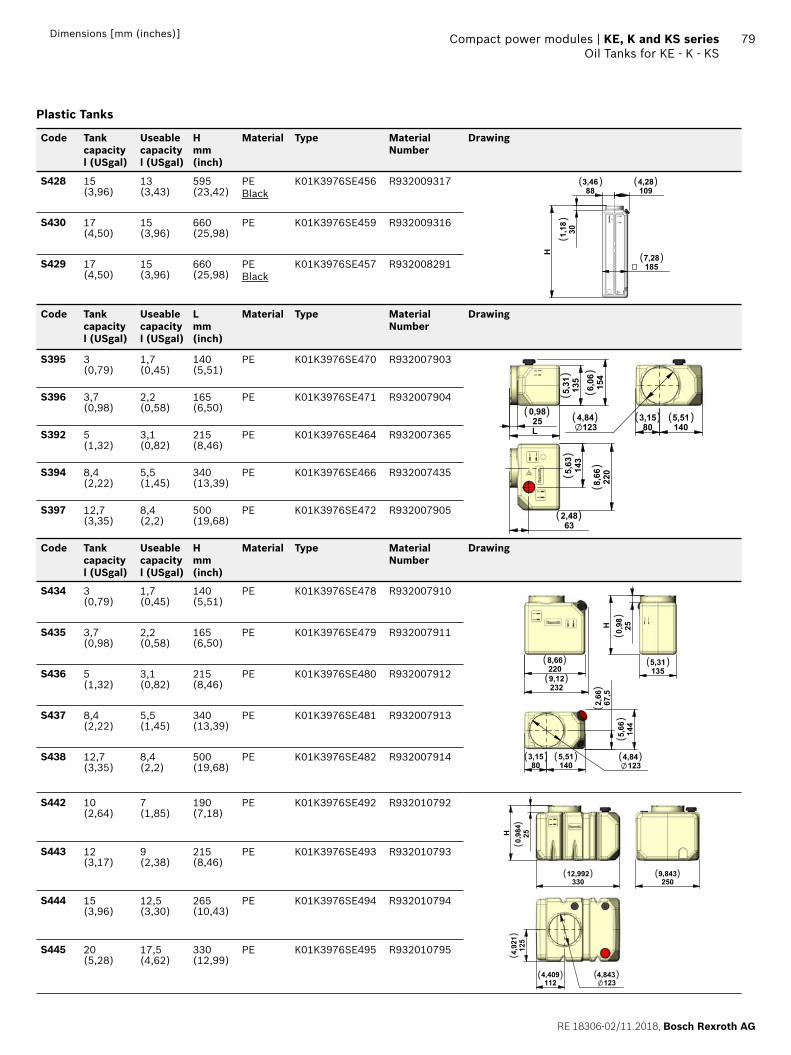
RE 18306-02/11.2018, Bosch Rexroth AG
Compact power modules | KE, K and KS series Oil Tanks for KE - K - KS
79Dimensions [mm (inches)]
Plastic Tanks
Code Tank capacityl (USgal)
Useable capacityl (USgal)
H mm(inch)
Material Type MaterialNumber
Drawing
S428 15(3,96)
13(3,43)
595(23,42)
PEBlack
K01K3976SE456 R932009317
1857,28
1094,28
883,46
301,18
H
( ) ( )
( )
()S430 17
(4,50)15(3,96)
660(25,98)
PE K01K3976SE459 R932009316
S429 17(4,50)
15(3,96)
660(25,98)
PEBlack
K01K3976SE457 R932008291
Code Tank capacityl (USgal)
Useable capacityl (USgal)
L mm(inch)
Material Type MaterialNumber
Drawing
S395 3(0,79)
1,7(0,45)
140(5,51)
PE K01K3976SE470 R932007903
250,98
L
135
5,31 154
6,06
803,15
1405,51
1234,84
220
8,66
632,48
143
5,63
( ) ( ) ( ) ( )
( )
()
()
()
()
S396 3,7(0,98)
2,2(0,58)
165(6,50)
PE K01K3976SE471 R932007904
S392 5(1,32)
3,1(0,82)
215(8,46)
PE K01K3976SE464 R932007365
S394 8,4(2,22)
5,5(1,45)
340(13,39)
PE K01K3976SE466 R932007435
S397 12,7(3,35)
8,4(2,2)
500(19,68)
PE K01K3976SE472 R932007905
Code Tank capacityl (USgal)
Useable capacityl (USgal)
Hmm(inch)
Material Type MaterialNumber
Drawing
S434 3(0,79)
1,7(0,45)
140(5,51)
PE K01K3976SE478 R932007910
2208,66
2329,12
250,98H
1355,31
803,15
1405,51
67,5
2,66
1234,84
144
5,66
( )
( )
( )
( ) ( )( )
()
()
()
S435 3,7(0,98)
2,2(0,58)
165(6,50)
PE K01K3976SE479 R932007911
S436 5(1,32)
3,1(0,82)
215(8,46)
PE K01K3976SE480 R932007912
S437 8,4(2,22)
5,5(1,45)
340(13,39)
PE K01K3976SE481 R932007913
S438 12,7(3,35)
8,4(2,2)
500(19,68)
PE K01K3976SE482 R932007914
S442 10(2,64)
7(1,85)
190(7,18)
PE K01K3976SE492 R932010792
H
33012,992
250,984
125
4,921
1124,409
1234,843
2509,843
( ) ( )
( )( )
()
()
S443 12(3,17)
9(2,38)
215(8,46)
PE K01K3976SE493 R932010793
S444 15(3,96)
12,5(3,30)
265(10,43)
PE K01K3976SE494 R932010794
S445 20(5,28)
17,5(4,62)
330(12,99)
PE K01K3976SE495 R932010795
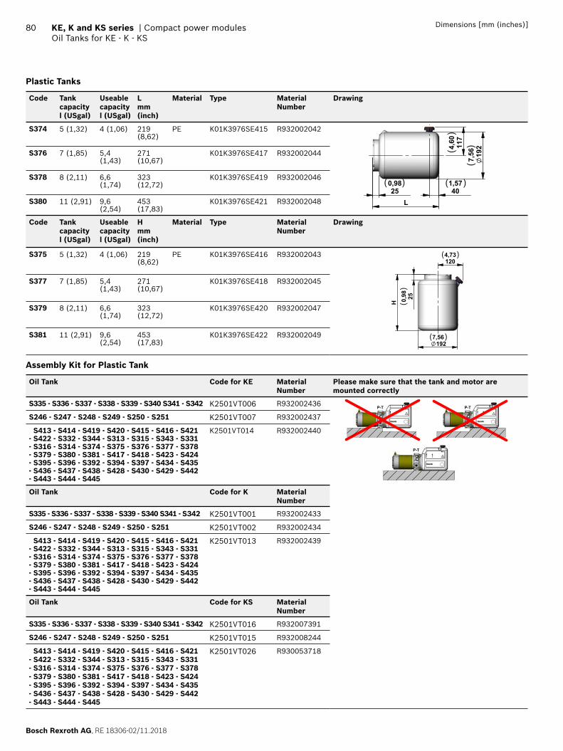
Bosch Rexroth AG, RE 18306-02/11.2018
80 KE, K and KS series | Compact power modulesOil Tanks for KE - K - KS
Dimensions [mm (inches)]
Plastic Tanks
Code Tank capacityl (USgal)
Useable capacityl (USgal)
L mm(inch)
Material Type MaterialNumber
Drawing
S374 5 (1,32) 4 (1,06) 219 (8,62)
PE K01K3976SE415 R932002042
250,98
L
192
7,56
401,57
117
4,60
( ) ( )
()
()
S376 7 (1,85) 5,4 (1,43)
271 (10,67)
K01K3976SE417 R932002044
S378 8 (2,11) 6,6 (1,74)
323 (12,72)
K01K3976SE419 R932002046
S380 11 (2,91) 9,6 (2,54)
453 (17,83)
K01K3976SE421 R932002048
Code Tank capacityl (USgal)
Useable capacityl (USgal)
H mm(inch)
Material Type MaterialNumber
Drawing
S375 5 (1,32) 4 (1,06) 219 (8,62)
PE K01K3976SE416 R932002043
1927,56
H
250,98
1204,73( )
( )
()
S377 7 (1,85) 5,4 (1,43)
271 (10,67)
K01K3976SE418 R932002045
S379 8 (2,11) 6,6 (1,74)
323 (12,72)
K01K3976SE420 R932002047
S381 11 (2,91) 9,6 (2,54)
453 (17,83)
K01K3976SE422 R932002049
Assembly Kit for Plastic Tank
Oil Tank Code for KE Material Number
Please make sure that the tank and motor are mounted correctly
S335 - S336 - S337 - S338 - S339 - S340 S341 - S342 K2501VT006 R932002436 P-T P-T
P-T
S246 - S247 - S248 - S249 - S250 - S251 K2501VT007 R932002437
S413 - S414 - S419 - S420 - S415 - S416 - S421 - S422 - S332 - S344 - S313 - S315 - S343 - S331 - S316 - S314 - S374 - S375 - S376 - S377 - S378 - S379 - S380 - S381 - S417 - S418 - S423 - S424 - S395 - S396 - S392 - S394 - S397 - S434 - S435 - S436 - S437 - S438 - S428 - S430 - S429 - S442 - S443 - S444 - S445
K2501VT014 R932002440
Oil Tank Code for K Material Number
S335 - S336 - S337 - S338 - S339 - S340 S341 - S342 K2501VT001 R932002433
S246 - S247 - S248 - S249 - S250 - S251 K2501VT002 R932002434
S413 - S414 - S419 - S420 - S415 - S416 - S421 - S422 - S332 - S344 - S313 - S315 - S343 - S331 - S316 - S314 - S374 - S375 - S376 - S377 - S378 - S379 - S380 - S381 - S417 - S418 - S423 - S424 - S395 - S396 - S392 - S394 - S397 - S434 - S435 - S436 - S437 - S438 - S428 - S430 - S429 - S442 - S443 - S444 - S445
K2501VT013 R932002439
Oil Tank Code for KS Material Number
S335 - S336 - S337 - S338 - S339 - S340 S341 - S342 K2501VT016 R932007391
S246 - S247 - S248 - S249 - S250 - S251 K2501VT015 R932008244
S413 - S414 - S419 - S420 - S415 - S416 - S421 - S422 - S332 - S344 - S313 - S315 - S343 - S331 - S316 - S314 - S374 - S375 - S376 - S377 - S378 - S379 - S380 - S381 - S417 - S418 - S423 - S424 - S395 - S396 - S392 - S394 - S397 - S434 - S435 - S436 - S437 - S438 - S428 - S430 - S429 - S442 - S443 - S444 - S445
K2501VT026 R930053718
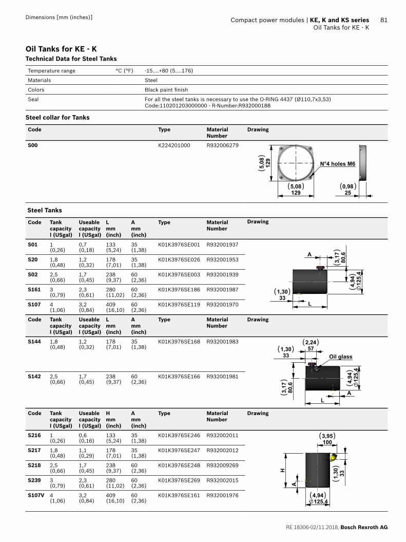
RE 18306-02/11.2018, Bosch Rexroth AG
Compact power modules | KE, K and KS series Oil Tanks for KE - K
81Dimensions [mm (inches)]
Oil Tanks for KE - KTechnical Data for Steel Tanks
Temperature range °C (°F) -15....+80 (5....176)
Materials Steel
Colors Black paint fi nish
Seal For all the steel tanks is necessary to use the O-RING 4437 (Ø110,7x3,53) Code:110201203000000 - R-Number:R932000188
Steel collar for Tanks
Code Type MaterialNumber
Drawing
S00 K224201000 R932006279
250,98
1295,08
129
5,08 N°4 holes M6
( ) ( )
()
Steel Tanks
Code Tank capacityl (USgal)
Useable capacityl (USgal)
Lmm(inch)
Amm(inch)
Type MaterialNumber
Drawing
S01 1(0,26)
0,7(0,18)
133(5,24)
35(1,38)
K01K3976SE001 R932001937
L331,30
125,4
4,94
80,6
3,17A
( )
()
()
S20 1,8(0,48)
1,2(0,32)
178(7,01)
35(1,38)
K01K3976SE026 R932001953
S02 2,5(0,66)
1,7(0,45)
238(9,37)
60(2,36)
K01K3976SE003 R932001939
S161 3(0,79)
2,3(0,61)
280(11,02)
60(2,36)
K01K3976SE186 R932001987
S107 4(1,06)
3,2(0,84)
409(16,10)
60(2,36)
K01K3976SE119 R932001970
Code Tank capacityl (USgal)
Useable capacityl (USgal)
Lmm(inch)
Amm(inch)
Type MaterialNumber
Drawing
S144 1,8(0,48)
1,2(0,32)
178(7,01)
35(1,38)
K01K3976SE168 R932001983
LA
331,30 57
2,24
125,
44,
94
80,6
3,17
Oil glass
( )( )
()
()S142 2,5
(0,66)1,7(0,45)
238(9,37)
60(2,36)
K01K3976SE166 R932001981
Code Tank capacityl (USgal)
Useable capacityl (USgal)
Hmm(inch)
Amm(inch)
Type MaterialNumber
Drawing
S216 1(0,26)
0,6(0,16)
133(5,24)
35(1,38)
K01K3976SE246 R932002011
H
A
125,44,94
1003,95
331,30
( )
( )
()
S217 1,8(0,48)
1,1(0,29)
178(7,01)
35(1,38)
K01K3976SE247 R932002012
S218 2,5(0,66)
1,7(0,45)
238(9,37)
60(2,36)
K01K3976SE248 R932009269
S239 3(0,79)
2,3(0,61)
280(11,02)
60(2,36)
K01K3976SE269 R932002015
S107V 4(1,06)
3,2(0,84)
409(16,10)
60(2,36)
K01K3976SE161 R932001976
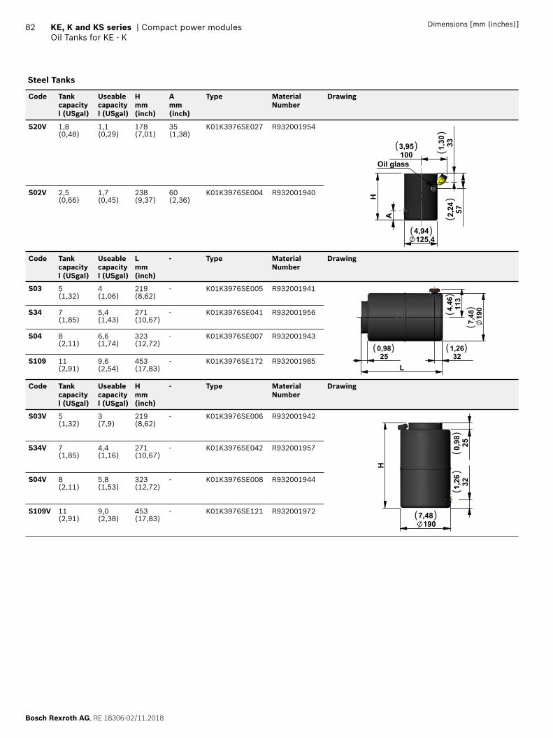
Bosch Rexroth AG, RE 18306-02/11.2018
82 KE, K and KS series | Compact power modulesOil Tanks for KE - K
Dimensions [mm (inches)]
Steel Tanks
Code Tank capacityl (USgal)
Useable capacityl (USgal)
Hmm(inch)
Amm(inch)
Type MaterialNumber
Drawing
S20V 1,8(0,48)
1,1(0,29)
178(7,01)
35(1,38)
K01K3976SE027 R932001954
H
A
125,44,94
1003,95
572,24
331,30
Oil glass
( )
( )
()
()
S02V 2,5(0,66)
1,7(0,45)
238(9,37)
60(2,36)
K01K3976SE004 R932001940
Code Tank capacityl (USgal)
Useable capacityl (USgal)
Lmm(inch)
- Type MaterialNumber
Drawing
S03 5(1,32)
4(1,06)
219(8,62)
- K01K3976SE005 R932001941
250,98
190
7,48
113
4,46
321,26
L
( )( )
()
()S34 7
(1,85)5,4(1,43)
271(10,67)
- K01K3976SE041 R932001956
S04 8(2,11)
6,6(1,74)
323(12,72)
- K01K3976SE007 R932001943
S109 11(2,91)
9,6(2,54)
453(17,83)
- K01K3976SE172 R932001985
Code Tank capacityl (USgal)
Useable capacityl (USgal)
Hmm(inch)
- Type MaterialNumber
Drawing
S03V 5(1,32)
3(7,9)
219(8,62)
- K01K3976SE006 R932001942
1907,48
321,26
250,98
H
( )
()
()
S34V 7(1,85)
4,4(1,16)
271(10,67)
- K01K3976SE042 R932001957
S04V 8(2,11)
5,8(1,53)
323(12,72)
- K01K3976SE008 R932001944
S109V 11(2,91)
9,0(2,38)
453(17,83)
- K01K3976SE121 R932001972
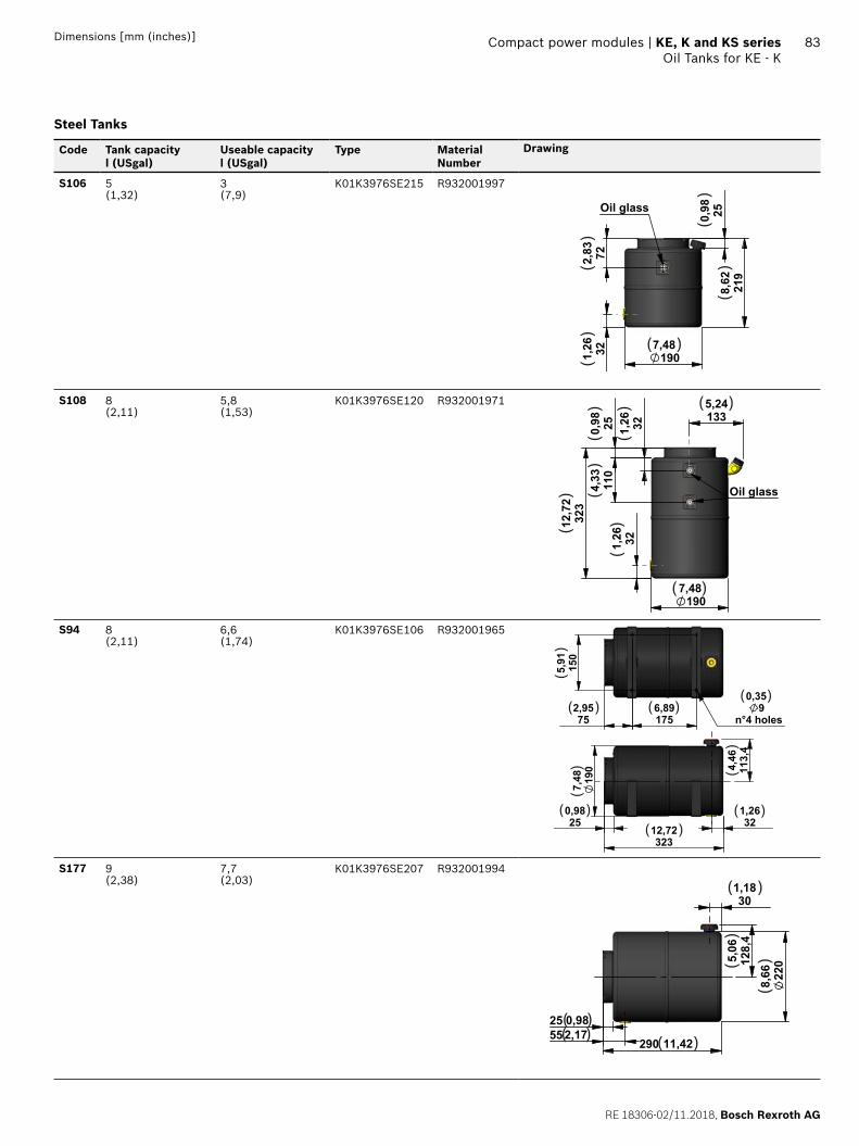
RE 18306-02/11.2018, Bosch Rexroth AG
Compact power modules | KE, K and KS series Oil Tanks for KE - K
83Dimensions [mm (inches)]
Steel Tanks
Code Tank capacityl (USgal)
Useable capacityl (USgal)
Type MaterialNumber
Drawing
S106 5(1,32)
3(7,9)
K01K3976SE215 R932001997
219
8,62
250,98
1907,48321,
26722,83
Oil glass
( )
()
()
()
()
S108 8(2,11)
5,8(1,53)
K01K3976SE120 R932001971
1907,48
321,26
323
12,7
2
250,98
110
4,33
321,26 133
5,24
Oil glass
( )
( )(
)(
)(
)
()
()
S94 8(2,11)
6,6(1,74)
K01K3976SE106 R932001965
32312,72
250,98
321,26
113,
44,
46
190
7,48
150
5,91
1756,89
752,95 9
n°4 holes
0,35( )
( )( )
( ) ( )( )
()
()
()
S177 9(2,38)
7,7(2,03)
K01K3976SE207 R932001994
25 0,98552,17
290 11,42
220
8,66128,4
5,06
301,18( )
( )( ) ( )
()
()
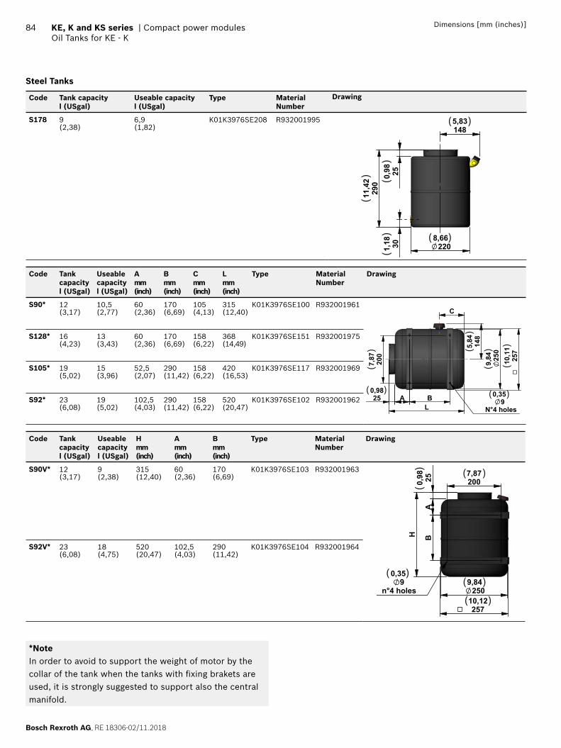
Bosch Rexroth AG, RE 18306-02/11.2018
84 KE, K and KS series | Compact power modulesOil Tanks for KE - K
Dimensions [mm (inches)]
Steel Tanks
Code Tank capacityl (USgal)
Useable capacityl (USgal)
Type MaterialNumber
Drawing
S178 9(2,38)
6,9(1,82)
K01K3976SE208 R932001995
301,18
250,98
290
11,42
1485,83
2208,66
( )
( )
()
()
()
Code Tank capacityl (USgal)
Useable capacityl (USgal)
Amm(inch)
Bmm(inch)
Cmm(inch)
Lmm(inch)
Type MaterialNumber
Drawing
S90* 12(3,17)
10,5(2,77)
60(2,36)
170(6,69)
105(4,13)
315(12,40)
K01K3976SE100 R932001961
250,98
A BL
200
7,87 25
09,
84 257
10,1
1148
5,84
C
9 N°4 holes
0,35( ) ( )
() (
)
()
()
S128* 16(4,23)
13(3,43)
60(2,36)
170(6,69)
158(6,22)
368(14,49)
K01K3976SE151 R932001975
S105* 19(5,02)
15(3,96)
52,5(2,07)
290(11,42)
158(6,22)
420(16,53)
K01K3976SE117 R932001969
S92* 23(6,08)
19(5,02)
102,5(4,03)
290(11,42)
158(6,22)
520(20,47)
K01K3976SE102 R932001962
Code Tank capacityl (USgal)
Useable capacityl (USgal)
Hmm(inch)
Amm(inch)
Bmm(inch)
Type MaterialNumber
Drawing
S90V* 12(3,17)
9(2,38)
315(12,40)
60(2,36)
170(6,69)
K01K3976SE103 R932001963
2509,84
25710,12
H
250,98
AB
2007,87
9n°4 holes
0,35
( )
( )( )
( )
()
S92V* 23(6,08)
18(4,75)
520(20,47)
102,5(4,03)
290(11,42)
K01K3976SE104 R932001964
*NoteIn order to avoid to support the weight of motor by the collar of the tank when the tanks with fi xing brakets are used, it is strongly suggested to support also the central manifold.
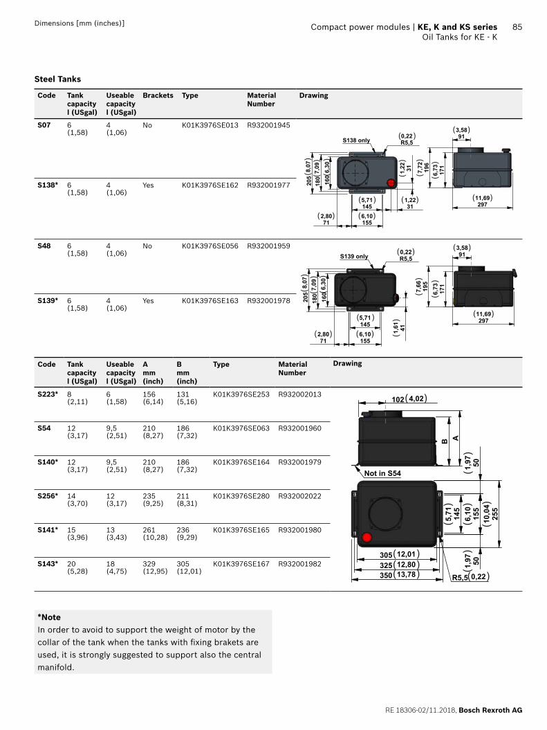
RE 18306-02/11.2018, Bosch Rexroth AG
Compact power modules | KE, K and KS series Oil Tanks for KE - K
85Dimensions [mm (inches)]
Steel Tanks
Code Tank capacityl (USgal)
Useable capacityl (USgal)
Brackets Type MaterialNumber
Drawing
S07 6(1,58)
4(1,06)
No K01K3976SE013 R932001945
1455,71
1556,10
712,80
311,22
311,22
160
6,30
180
7,09
205
8,07
R5,50,22
S138 only
29711,69
913,58
171
6,7319
67,
72
( )( )
( )( )
( )( )
( )
()
()
()
()
()
()
S138* 6(1,58)
4(1,06)
Yes K01K3976SE162 R932001977
S48 6(1,58)
4(1,06)
No K01K3976SE056 R932001959
1455,71
1556,10
712,80
160
6,30
180
7,09
205
8,07
R5,50,22
411,61
S139 only 913,58
195
7,66
29711,69
171
6,73
( )( )
( )
( )( )
( )
()
()
()
()
()
()
S139* 6(1,58)
4(1,06)
Yes K01K3976SE163 R932001978
Code Tank capacityl (USgal)
Useable capacityl (USgal)
Amm(inch)
Bmm(inch)
Type MaterialNumber
Drawing
S223* 8(2,11)
6(1,58)
156(6,14)
131(5,16)
K01K3976SE253 R932002013
B A
102 4,02
Not in S54
325 12,80
145
5,71 155
6,10
501,97
501,97
350 13,78
305 12,01
255
10,0
4
R5,5 0,22
( )
( )( )( )( )
()
()
()
()
()
S54 12(3,17)
9,5(2,51)
210(8,27)
186(7,32)
K01K3976SE063 R932001960
S140* 12(3,17)
9,5(2,51)
210(8,27)
186(7,32)
K01K3976SE164 R932001979
S256* 14(3,70)
12(3,17)
235(9,25)
211(8,31)
K01K3976SE280 R932002022
S141* 15(3,96)
13(3,43)
261(10,28)
236(9,29)
K01K3976SE165 R932001980
S143* 20(5,28)
18(4,75)
329(12,95)
305(12,01)
K01K3976SE167 R932001982
*Note In order to avoid to support the weight of motor by the collar of the tank when the tanks with fi xing brakets are used, it is strongly suggested to support also the central manifold.
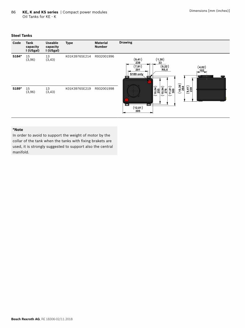
Bosch Rexroth AG, RE 18306-02/11.2018
86 KE, K and KS series | Compact power modulesOil Tanks for KE - K
Dimensions [mm (inches)]
Steel Tanks
Code Tank capacityl (USgal)
Useable capacityl (USgal)
Type MaterialNumber
Drawing
S184* 15(3,96)
13(3,43)
K01K3976SE214 R932001996
30512,01
278
10,9
425
510
,04
300
11,8
1
2399,41
2017,91
R5,50,22
331,30
S189 only1024,02
239
9,4126
410
,39
( ) ( )
( ) ( ) ( )
( )
()
()
()
()
()
S189* 15(3,96)
13(3,43)
K01K3976SE219 R932001998
*NoteIn order to avoid to support the weight of motor by the collar of the tank when the tanks with fi xing brakets are used, it is strongly suggested to support also the central manifold.
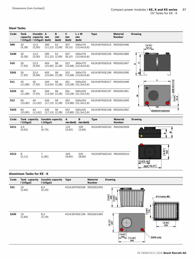
RE 18306-02/11.2018, Bosch Rexroth AG
Compact power modules | KE, K and KS series Oil Tanks for KE - K
87Dimensions [mm (inches)]
Steel Tanks
Code Tank capacityl (USgal)
Useable capacityl (USgal)
Amm(inch)
Bmm(inch)
Cmm(inch)
L x Wmm(inch)
Type MaterialNumber
Drawing
S09 20(5,28)
12,5(3,30)
285(11,22)
53(2,09)
207(8,15)
340x270(13,4x10,6)
K01K3976SE015 R932001946
BCA
121,54,78
W
L
21,4
0,84
S240/241/242/243
S09/10/11/12
( )
()
S240 20(5,28)
12,5(3,30)
285(11,22)
53(2,09)
207(8,15)
340x270(13,4x10,6)
K01K3976SE195 R932001989
S10 30(7,92)
22,5(5,94)
405(15,94)
58(2,28)
322(12,68)
340x270(13,4x10,6)
K01K3976SE016 R932001947
S241 30(7,92)
22,5(5,94)
405(15,94)
58(2,28)
322(12,68)
340x270(13,4x10,6)
K01K3976SE196 R932001990
S11 45(11,89)
30(7,92)
344(13,54)
58(2,28)
261(10,28)
540x320(21,3x12,6)
K01K3976SE017 R932001948
S242 45(11,89)
30(7,92)
344(13,54)
58(2,28)
261(10,28)
540x320(21,3x12,6)
K01K3976SE197 R932001991
S12 60(15,85)
44(11,62)
435(17,13)
58(2,28)
352(13,86)
540x320(21,3x12,6)
K01K3976SE018 R932001949
S243 60(15,85)
44(11,62)
435(17,13)
58(2,28)
352(13,86)
540x320(21,3x12,6)
K01K3976SE198 R932001992
Code Tank capacityl (USgal)
Useable capacityl (USgal)
Amm (inch)
Bmm (inch)
Type MaterialNumber
Drawing
S211 3,5(0,92)
3(0,79)
125(4,92)
100(3,94)
K01K3976SE241 R932002009
131 5,16
262 10,31167
6,57
A B
( )( )
()
S212 8(2,11)
7(1,85)
245(9,65)
220(8,66)
K01K3976SE242 R932002010
Aluminium Tanks for KE - K
Code Tank capacityl (USgal)
Useable capacityl (USgal)
Type MaterialNumber
Drawing
S31 10(2,64)
8,3(2,19)
K01K3976SE038 R932001955
227
8,9425
29,
92
34013,39
247
9,72
1024,02
S245 only
2509,84
170
6,69
N°4 holes M8
( )
( )
( )
()
()
()
()
S245 10(2,64)
8,3(2,19)
K01K3976SE199 R932001993
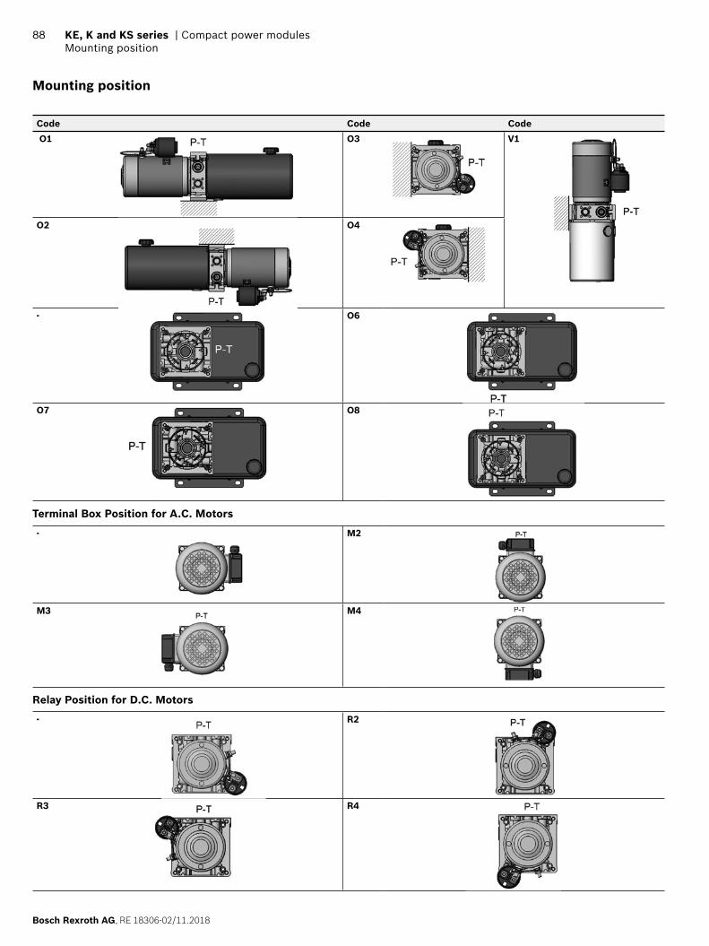
Bosch Rexroth AG, RE 18306-02/11.2018
88 KE, K and KS series | Compact power modulesMounting position
Mounting position
Code Code Code
O1 O3 V1
O2 O4
- O6
O7 O8
Terminal Box Position for A.C. Motors
- M2
M3 M4
Relay Position for D.C. Motors
- R2
R3 R4
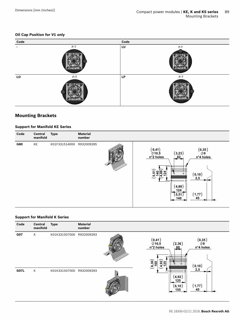
RE 18306-02/11.2018, Bosch Rexroth AG
Compact power modules | KE, K and KS series Mounting Brackets
89Dimensions [mm (inches)]
Oil Cap Position for V1 only
Code Code
- LU
LO LP
Mounting Brackets
Support for Manifold KE Series
Code Central manifold
Type Material number
G80 KE K01F331514000 R932009395
451,77
2,50,1012
44,
88140
5,51
1244,88
1405,51
823,23 9
n°4 holes
0,3510,5
n°2 holes
0,41( )( )
( )
( )
( )
( )
( )
()
()
Support for Manifold K Series
Code Central manifold
Type Material number
G07 K K01K331507000 R932009393
451,77
2,50,1012
54,
92160
6,30
1254,92
1556,10
602,36 9
n°4 holes
0,3510,5
n°2 holes
0,41( )
( ) ( )
( )
( )( )
( )
()
()
G07L K K01K331507000 R932009393
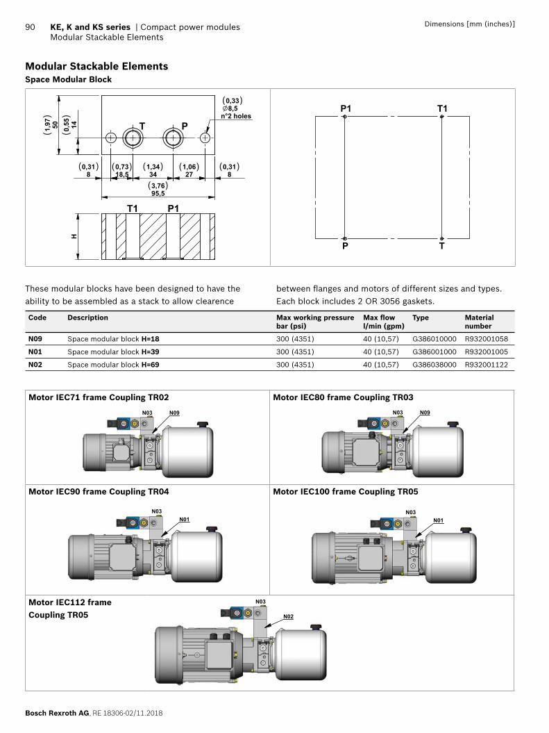
Bosch Rexroth AG, RE 18306-02/11.2018
90 KE, K and KS series | Compact power modulesModular Stackable Elements
Dimensions [mm (inches)]
Modular Stackable Elements Space Modular Block
140,55501,97
80,31
18,50,73
341,34
271,06
80,31
95,53,76
8,5n°2 holes
0,33
PT
P1T1
H
( ) ( ) ( )
( )
( ) ( )
( )
()
()
P T
P1 T1
These modular blocks have been designed to have the ability to be assembled as a stack to allow clearence
between fl anges and motors of different sizes and types.Each block includes 2 OR 3056 gaskets.
Code Description Max working pressure bar (psi)
Max fl ow l/min (gpm)
Type Material number
N09 Space modular block H=18 300 (4351) 40 (10,57) G386010000 R932001058
N01 Space modular block H=39 300 (4351) 40 (10,57) G386001000 R932001005
N02 Space modular block H=69 300 (4351) 40 (10,57) G386038000 R932001122
Motor IEC71 frame Coupling TR02 Motor IEC80 frame Coupling TR03
N03 N09 N03 N09
Motor IEC90 frame Coupling TR04 Motor IEC100 frame Coupling TR05
N03N01
N03N01
Motor IEC112 frame Coupling TR05
N03
N02
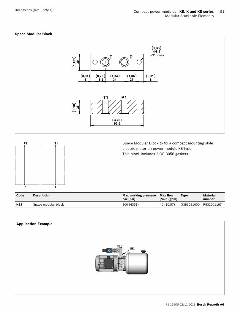
RE 18306-02/11.2018, Bosch Rexroth AG
Compact power modules | KE, K and KS series Modular Stackable Elements
91Dimensions [mm (inches)]
Space Modular Block
80,31
18,50,73
341,34
271,06
80,31
8,5n°2 holes
0,33
301,18
1 PT
P1T1
250,98
95,53,76
( ) ( ) ( )
( )
( ) ( )
( )
()
()
P T
P1 T1 Space Modular Block to fi x a compact mounting style electric motor on power module KE type.This block includes 2 OR 3056 gaskets.
Code Description Max working pressure bar (psi)
Max fl ow l/min (gpm)
Type Material number
N92 Space modular block 300 (4351) 40 (10,57) G386091000 R932001167
Application Example
N03N92
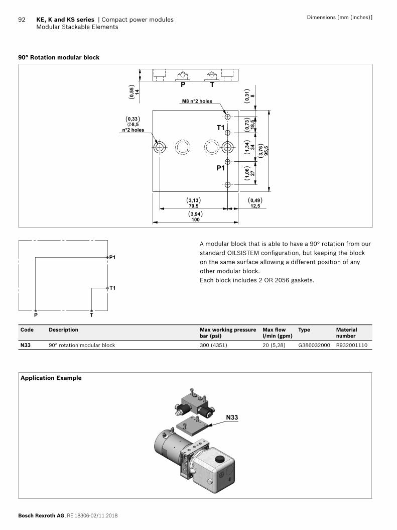
Bosch Rexroth AG, RE 18306-02/11.2018
92 KE, K and KS series | Compact power modulesModular Stackable Elements
Dimensions [mm (inches)]
90° Rotation modular block
1003,94
12,50,49
79,53,13
8,5n°2 holes
0,33
M8 n°2 holes
80,
3118
,50,
73341,34
271,06
95,5
3,76
P1
T1140,55
P T
( )
( )
( )
( )
()
()
()
()
()
()
P T
P1
T1
A modular block that is able to have a 90° rotation from our standard OILSISTEM confi guration, but keeping the block on the same surface allowing a different position of any other modular block.Each block includes 2 OR 2056 gaskets.
Code Description Max working pressure bar (psi)
Max fl ow l/min (gpm)
Type Material number
N33 90° rotation modular block 300 (4351) 20 (5,28) G386032000 R932001110
Application Example
N33
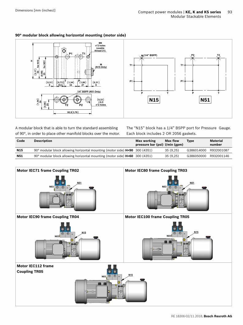
RE 18306-02/11.2018, Bosch Rexroth AG
Compact power modules | KE, K and KS series Modular Stackable Elements
93Dimensions [mm (inches)]
90° modular block allowing horizontal mounting (motor side)
80,31
271,06
341,34
18,50,73
80,31
55 fo
r N15
2,17
H
thread 21)
M8n°2 holes(usable
25
fo
r N51
M(N15 Only)
P1 T1
PT
(0,9
8)
250,98
391,54
95,5 3,76
8,5n°2 holes
0,33
P2T2
1/4" BSPP (N51 Only)
( ) ( ) ( ) ( ) ( )
( )
( )
()
()
()
P T
M (1/4" BSPP)
T1
P1
P T
T1
P1
P2 T2
N15 N51
A modular block that is able to turn the standard assembling of 90°, in order to place other manifold blocks over the motor.
The “N15” block has a 1/4” BSPP port for Pressure Gauge.Each block includes 2 OR 2056 gaskets.
Code Description Max working pressure bar (psi)
Max fl ow l/min (gpm)
Type Material number
N15 90° modular block allowing horizontal mounting (motor side) H=90 300 (4351) 35 (9,25) G386014000 R932001087
N51 90° modular block allowing horizontal mounting (motor side) H=60 300 (4351) 35 (9,25) G386050000 R932001146
Motor IEC71 frame Coupling TR02 Motor IEC80 frame Coupling TR03
N03N51
N03N51
Motor IEC90 frame Coupling TR04 Motor IEC100 frame Coupling TR05
N03N15
N03N15
Motor IEC112 frame Coupling TR05
N03N15
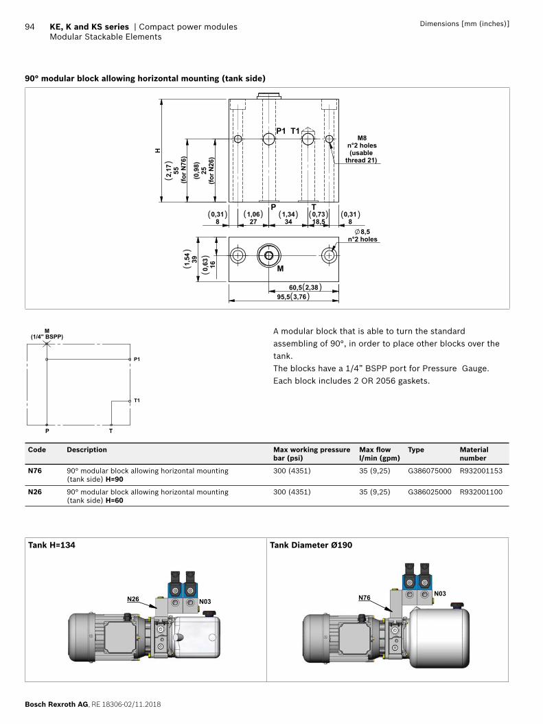
Bosch Rexroth AG, RE 18306-02/11.2018
94 KE, K and KS series | Compact power modulesModular Stackable Elements
Dimensions [mm (inches)]
90° modular block allowing horizontal mounting (tank side)
80,31
18,50,73
341,34
271,06
80,31
55(fo
r N76
)
2,17
Hthread 21)
M8n°2 holes(usable
(for N
26)
25
P1 T1
P T160,63391,
54
60,5 2,3895,5 3,76
8,5n°2 holes
M
(0,9
8)
( ) ( ) ( ) ( )
( )( )
( )
()
()
()
P T
M(1/4" BSPP)
P1
T1
A modular block that is able to turn the standard assembling of 90°, in order to place other blocks over the tank.The blocks have a 1/4” BSPP port for Pressure Gauge.Each block includes 2 OR 2056 gaskets.
Code Description Max working pressure bar (psi)
Max fl ow l/min (gpm)
Type Material number
N76 90° modular block allowing horizontal mounting (tank side) H=90
300 (4351) 35 (9,25) G386075000 R932001153
N26 90° modular block allowing horizontal mounting (tank side) H=60
300 (4351) 35 (9,25) G386025000 R932001100
Tank H=134 Tank Diameter Ø190
N03N26N03N76
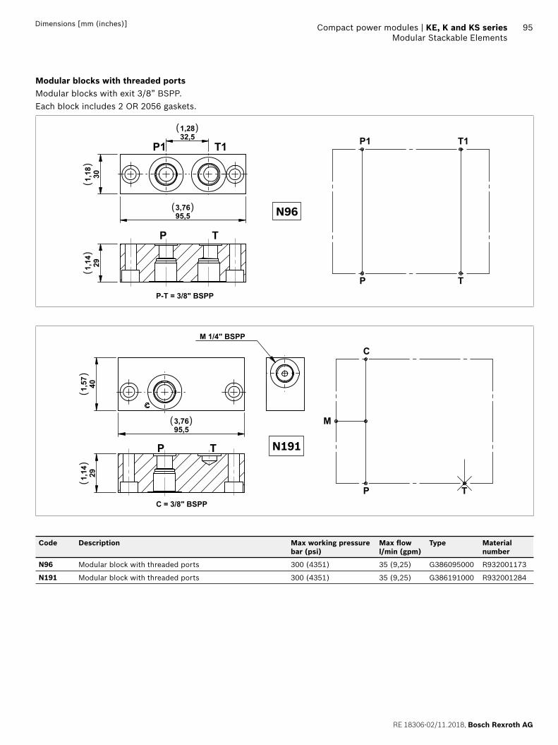
RE 18306-02/11.2018, Bosch Rexroth AG
Compact power modules | KE, K and KS series Modular Stackable Elements
95Dimensions [mm (inches)]
Modular blocks with threaded portsModular blocks with exit 3/8” BSPP.Each block includes 2 OR 2056 gaskets.
95,53,76
301,18
32,51,28
P1 T1
P T
291,14
P-T = 3/8" BSPP
( )
( )
()
()
P T
P1 T1
N96
95,53,76
401,57
291,14
M 1/4" BSPP
C = 3/8" BSPP
P T
( )
()
()
P T
C
M
N191
Code Description Max working pressure bar (psi)
Max fl ow l/min (gpm)
Type Material number
N96 Modular block with threaded ports 300 (4351) 35 (9,25) G386095000 R932001173
N191 Modular block with threaded ports 300 (4351) 35 (9,25) G386191000 R932001284
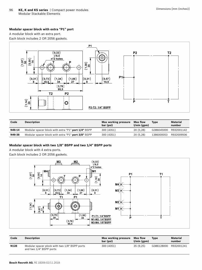
Bosch Rexroth AG, RE 18306-02/11.2018
96 KE, K and KS series | Compact power modulesModular Stackable Elements
Dimensions [mm (inches)]
Modular spacer block with extra “P1” portA modular block with an extra port.Each block includes 2 OR 2056 gaskets.
140,55501,97
80,31
18,50,73
341,34
271,06
80,31
95,53,76
8,5n°2 holes
0,33
T P
P2T2
P2-T2: 1/4" BSPP
291,14
P1
351,38
14,50,57
( )
( ) ( ) ( ) ( ) ( ) ( )
()
()
()
()
P T
P2
P1
T2
Code Description Max working pressure bar (psi)
Max fl ow l/min (gpm)
Type Material number
N46-14 Modular spacer block with extra "P1" port 1/4" BSPP 300 (4351) 20 (5,28) G386045000 R932001142
N46-38 Modular spacer block with extra "P1" port 3/8" BSPP 300 (4351) 20 (5,28) 1386000053 R932009506
Modular spacer block with two 1/8” BSPP and two 1/4” BSPP portsA modular block with 4 extra ports.Each block includes 2 OR 2056 gaskets.
80,31
18,50,73
341,34
271,06
140,55501,97
80,31
301,18
8,5 n°2 holes
0,33
341,34
95,53,76
170,67
200,79
351,38
M1PT
P1-T1: 1/4"BSPP
M2M3
M4
P1T1
M1-M2: 1/4"BSPPM3-M4: 1/8"BSPP
( )
( )( )( )( )( )
( ) ( )
( )
()
()
()
()
()
P T
P1 T1
M1
M2
M3
M4
Code Description Max working pressure bar (psi)
Max fl ow l/min (gpm)
Type Material number
N128 Modular spacer plock with two 1/8" BSPP ports and two 1/4" BSPP ports
300 (4351) 35 (9,25) G386128000 R932001241
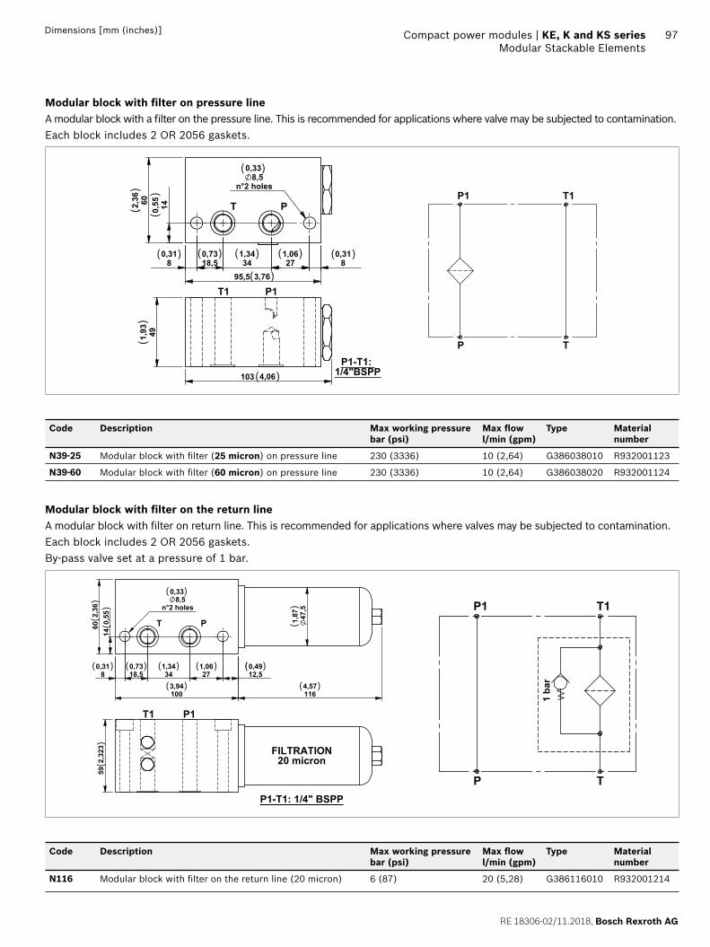
RE 18306-02/11.2018, Bosch Rexroth AG
Compact power modules | KE, K and KS series Modular Stackable Elements
97Dimensions [mm (inches)]
Modular block with fi lter on pressure lineA modular block with a fi lter on the pressure line. This is recommended for applications where valve may be subjected to contamination.Each block includes 2 OR 2056 gaskets.
80,31
271,06
341,34
18,50,73
80,31
140,55
95,5 3,76
602,36
8,5n°2 holes
0,33
T P
491,93
103 4,06
P1T1
P1-T1: 1/4"BSPP
( )
( ) ( ) ( )
( )
( ) ( )
( )
()
()
()
P T
P1 T1
Code Description Max working pressure bar (psi)
Max fl ow l/min (gpm)
Type Material number
N39-25 Modular block with fi lter (25 micron) on pressure line 230 (3336) 10 (2,64) G386038010 R932001123
N39-60 Modular block with fi lter (60 micron) on pressure line 230 (3336) 10 (2,64) G386038020 R932001124
Modular block with fi lter on the return lineA modular block with fi lter on return line. This is recommended for applications where valves may be subjected to contamination.Each block includes 2 OR 2056 gaskets.By-pass valve set at a pressure of 1 bar.
80,31
18,50,73
341,34
271,06
12,50,49
140,
5560
2,36
1003,94
1164,57
47,5
1,87
8,5n°2 holes
0,33
PT
592,
323 FILTRATION
20 micron
P1T1
P1-T1: 1/4" BSPP
( )
( ) ( ) ( ) ( ) ( )
( )( )
()
()
()
()
P T
P1 T1
1 ba
r
Code Description Max working pressure bar (psi)
Max fl ow l/min (gpm)
Type Material number
N116 Modular block with fi lter on the return line (20 micron) 6 (87) 20 (5,28) G386116010 R932001214
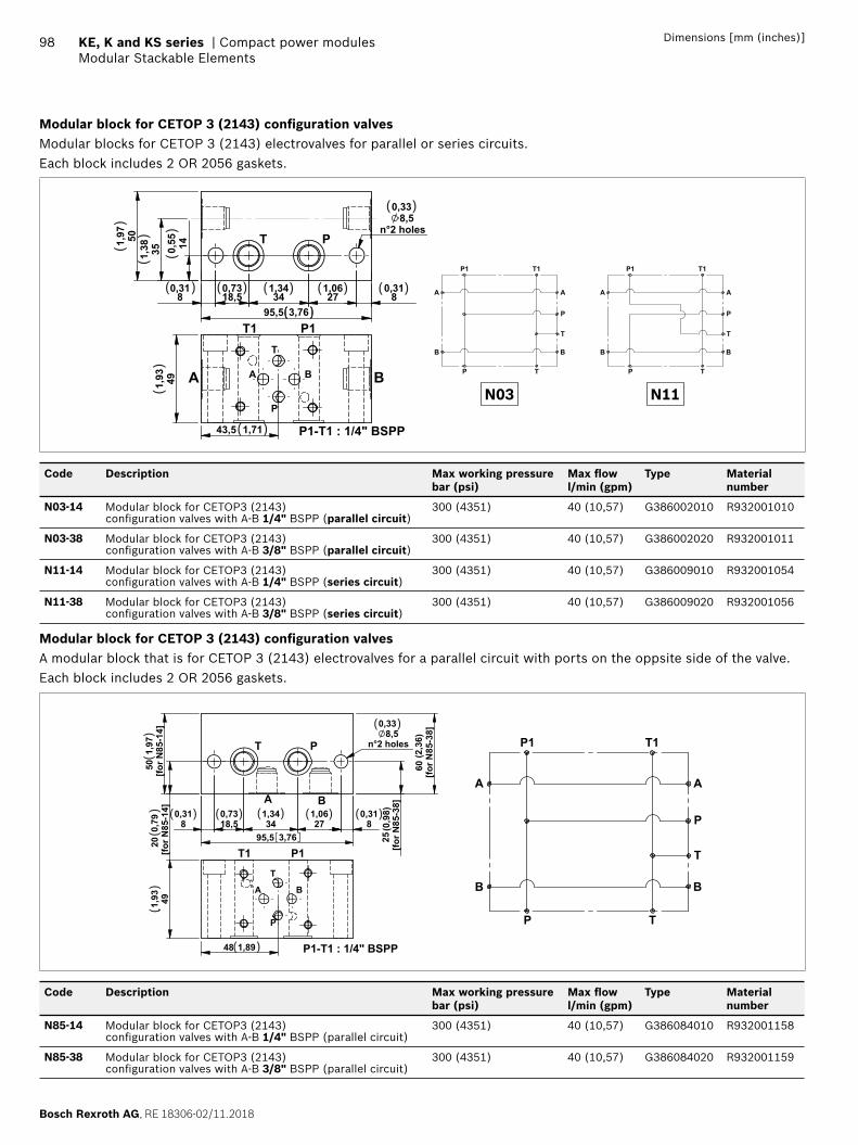
Bosch Rexroth AG, RE 18306-02/11.2018
98 KE, K and KS series | Compact power modulesModular Stackable Elements
Dimensions [mm (inches)]
Modular block for CETOP 3 (2143) confi guration valvesModular blocks for CETOP 3 (2143) electrovalves for parallel or series circuits.Each block includes 2 OR 2056 gaskets.
140,55501,
97
80,31
271,06
341,34
18,50,73
80,31
95,5 3,76
8,5n°2 holes
0,33
351,38
PT
43,5 1,71
491,93
P
B
T
AA B
T1 P1
P1-T1 : 1/4" BSPP
( ) ( ) ( ) ( ) ( )
( )
( )
( )
()
()
()
()
P T
P1 T1
A
B B
A
P
T
P T
P1 T1
A
B B
A
P
T
N03 N11
Code Description Max working pressure bar (psi)
Max fl ow l/min (gpm)
Type Material number
N03-14 Modular block for CETOP3 (2143) confi guration valves with A-B 1/4" BSPP (parallel circuit)
300 (4351) 40 (10,57) G386002010 R932001010
N03-38 Modular block for CETOP3 (2143) confi guration valves with A-B 3/8" BSPP (parallel circuit)
300 (4351) 40 (10,57) G386002020 R932001011
N11-14 Modular block for CETOP3 (2143) confi guration valves with A-B 1/4" BSPP (series circuit)
300 (4351) 40 (10,57) G386009010 R932001054
N11-38 Modular block for CETOP3 (2143) confi guration valves with A-B 3/8" BSPP (series circuit)
300 (4351) 40 (10,57) G386009020 R932001056
Modular block for CETOP 3 (2143) confi guration valvesA modular block that is for CETOP 3 (2143) electrovalves for a parallel circuit with ports on the oppsite side of the valve.Each block includes 2 OR 2056 gaskets.
80,31
271,06
341,34
18,50,73
80,31
95,5 3,76
20
[for N
85-1
4]0,
79
8,5n°2 holes
0,33
50 [f
or N
85-1
4]
1,97
[for N
85-3
8]25
[for
N85
-38]
60
A B
T P
(0,9
8)
(2,3
6)
48 1,89
491,93
T1 P1
P1-T1 : 1/4" BSPP
A B
P
T
( )
( )( )( )( )( )
( )
()
()
()
P T
P1 T1
A
B B
A
P
T
Code Description Max working pressure bar (psi)
Max fl ow l/min (gpm)
Type Material number
N85-14 Modular block for CETOP3 (2143) confi guration valves with A-B 1/4" BSPP (parallel circuit)
300 (4351) 40 (10,57) G386084010 R932001158
N85-38 Modular block for CETOP3 (2143) confi guration valves with A-B 3/8" BSPP (parallel circuit)
300 (4351) 40 (10,57) G386084020 R932001159
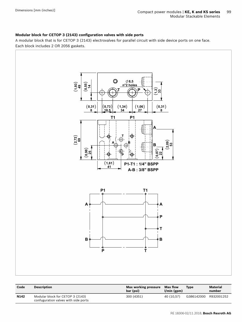
RE 18306-02/11.2018, Bosch Rexroth AG
Compact power modules | KE, K and KS series Modular Stackable Elements
99Dimensions [mm (inches)]
Modular block for CETOP 3 (2143) confi guration valves with side portsA modular block that is for CETOP 3 (2143) electrovalves for parallel circuit with side device ports on one face.Each block includes 2 OR 2056 gaskets.
140,55491,93
80,31
271,06
341,34
18,50,73
80,31
8,5n°2 holes
331,3T P
250,98
411,61
692,72
220,87
532,09A B
P
T
A
B
A-B : 3/8" BSPP
P1T1
P1-T1 : 1/4" BSPP
( ) ( ) ( ) ( ) ( )
( )
()
()
()
()
() (
)
()
P T
P1 T1
A
B B
A
P
T
Code Description Max working pressure bar (psi)
Max fl ow l/min (gpm)
Type Material number
N142 Modular block for CETOP 3 (2143) confuguration valves with side ports
300 (4351) 40 (10,57) G386142000 R932001252
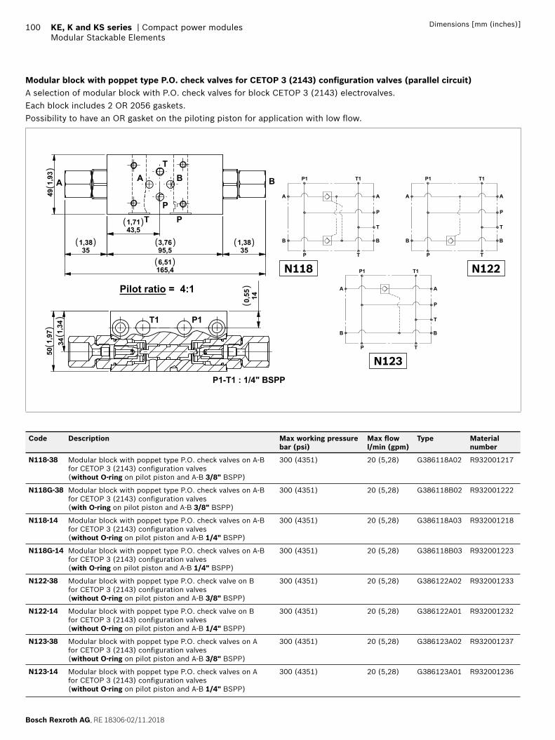
Bosch Rexroth AG, RE 18306-02/11.2018
100 KE, K and KS series | Compact power modulesModular Stackable Elements
Dimensions [mm (inches)]
Modular block with poppet type P.O. check valves for CETOP 3 (2143) confi guration valves (parallel circuit)A selection of modular block with P.O. check valves for block CETOP 3 (2143) electrovalves.Each block includes 2 OR 2056 gaskets.Possibility to have an OR gasket on the piloting piston for application with low fl ow.
43,51,71
95,53,76
351,38
351,38
165,46,51
491,
93 A B
P
T
PT
A B
501,
9734
1,34
140,55
P1T1
Pilot ratio = 4:1
P1-T1 : 1/4" BSPP
( )
( )
( )
( )
( )
()
()
()
()
P T
P1 T1
A
B B
A
P
T
P T
P1 T1
A
B B
A
P
T
P T
P1 T1
A
B B
A
P
T
N118 N122
N123
Code Description Max working pressure bar (psi)
Max fl ow l/min (gpm)
Type Material number
N118-38 Modular block with poppet type P.O. check valves on A-B for CETOP 3 (2143) confi guration valves (without O-ring on pilot piston and A-B 3/8" BSPP)
300 (4351) 20 (5,28) G386118A02 R932001217
N118G-38 Modular block with poppet type P.O. check valves on A-B for CETOP 3 (2143) confi guration valves (with O-ring on pilot piston and A-B 3/8" BSPP)
300 (4351) 20 (5,28) G386118B02 R932001222
N118-14 Modular block with poppet type P.O. check valves on A-B for CETOP 3 (2143) confi guration valves (without O-ring on pilot piston and A-B 1/4" BSPP)
300 (4351) 20 (5,28) G386118A03 R932001218
N118G-14 Modular block with poppet type P.O. check valves on A-B for CETOP 3 (2143) confi guration valves (with O-ring on pilot piston and A-B 1/4" BSPP)
300 (4351) 20 (5,28) G386118B03 R932001223
N122-38 Modular block with poppet type P.O. check valve on B for CETOP 3 (2143) confi guration valves (without O-ring on pilot piston and A-B 3/8" BSPP)
300 (4351) 20 (5,28) G386122A02 R932001233
N122-14 Modular block with poppet type P.O. check valve on B for CETOP 3 (2143) confi guration valves (without O-ring on pilot piston and A-B 1/4" BSPP)
300 (4351) 20 (5,28) G386122A01 R932001232
N123-38 Modular block with poppet type P.O. check valves on A for CETOP 3 (2143) confi guration valves (without O-ring on pilot piston and A-B 3/8" BSPP)
300 (4351) 20 (5,28) G386123A02 R932001237
N123-14 Modular block with poppet type P.O. check valves on A for CETOP 3 (2143) confi guration valves (without O-ring on pilot piston and A-B 1/4" BSPP)
300 (4351) 20 (5,28) G386123A01 R932001236
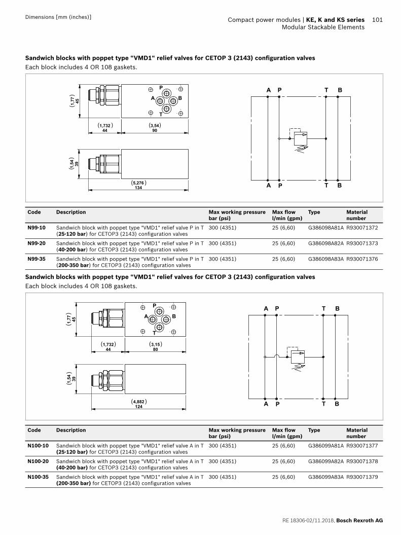
RE 18306-02/11.2018, Bosch Rexroth AG
Compact power modules | KE, K and KS series Modular Stackable Elements
101Dimensions [mm (inches)]
Sandwich blocks with poppet type “VMD1“ relief valves for CETOP 3 (2143) confi guration valvesEach block includes 4 OR 108 gaskets.
903,54
451,77
1,73244
A B
P
T
391,54
5,276134
( )( )
( )
()
()
A P
A P T
BT
B
Code Description Max working pressure bar (psi)
Max fl ow l/min (gpm)
Type Material number
N99-10 Sandwich block with poppet type "VMD1" relief valve P in T (25-120 bar) for CETOP3 (2143) confi guration valves
300 (4351) 25 (6,60) G386098A81A R930071372
N99-20 Sandwich block with poppet type "VMD1" relief valve P in T (40-200 bar) for CETOP3 (2143) confi guration valves
300 (4351) 25 (6,60) G386098A82A R930071373
N99-35 Sandwich block with poppet type "VMD1" relief valve P in T (200-350 bar) for CETOP3 (2143) confi guration valves
300 (4351) 25 (6,60) G386098A83A R930071376
Sandwich blocks with poppet type “VMD1“ relief valves for CETOP 3 (2143) confi guration valvesEach block includes 4 OR 108 gaskets.
803,15
451,77
1,73244
A B
P
T
391,54
4,882124
( ) ( )
( )
()
()
A P
A P T
BT
B
Code Description Max working pressure bar (psi)
Max fl ow l/min (gpm)
Type Material number
N100-10 Sandwich block with poppet type "VMD1" relief valve A in T (25-120 bar) for CETOP3 (2143) confi guration valves
300 (4351) 25 (6,60) G386099A81A R930071377
N100-20 Sandwich block with poppet type "VMD1" relief valve A in T (40-200 bar) for CETOP3 (2143) confi guration valves
300 (4351) 25 (6,60) G386099A82A R930071378
N100-35 Sandwich block with poppet type "VMD1" relief valve A in T (200-350 bar) for CETOP3 (2143) confi guration valves
300 (4351) 25 (6,60) G386099A83A R930071379
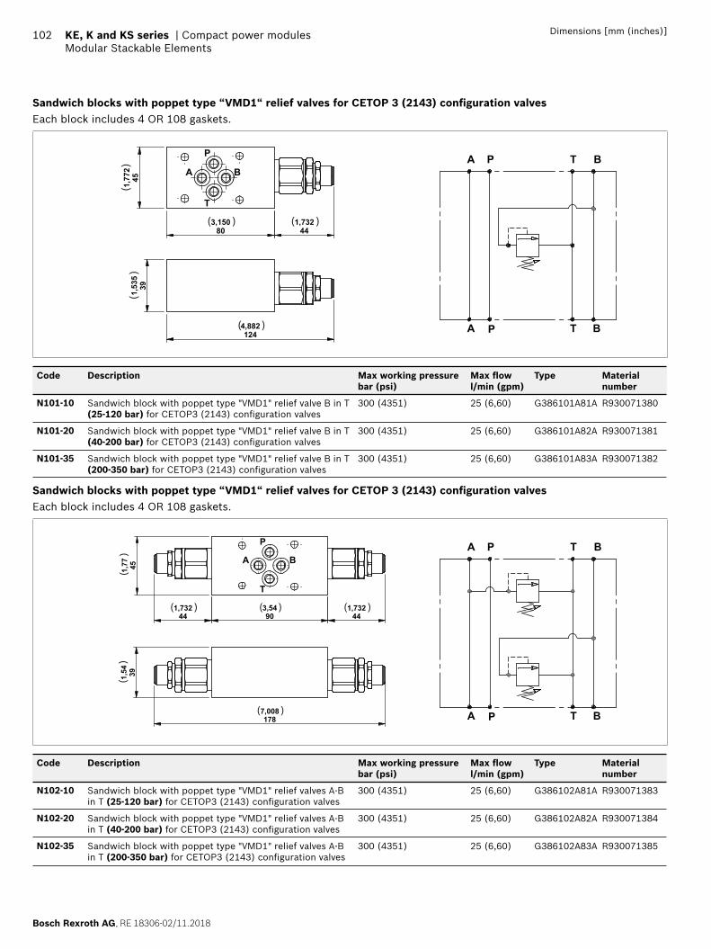
Bosch Rexroth AG, RE 18306-02/11.2018
102 KE, K and KS series | Compact power modulesModular Stackable Elements
Dimensions [mm (inches)]
Sandwich blocks with poppet type “VMD1“ relief valves for CETOP 3 (2143) confi guration valvesEach block includes 4 OR 108 gaskets.
1,772
45
3,15080
1,73244
A B
P
T
1,535
39
4,882124
( ) ( )
( )
()
()
A P
A P T
BT
B
Code Description Max working pressure bar (psi)
Max fl ow l/min (gpm)
Type Material number
N101-10 Sandwich block with poppet type "VMD1" relief valve B in T (25-120 bar) for CETOP3 (2143) confi guration valves
300 (4351) 25 (6,60) G386101A81A R930071380
N101-20 Sandwich block with poppet type "VMD1" relief valve B in T (40-200 bar) for CETOP3 (2143) confi guration valves
300 (4351) 25 (6,60) G386101A82A R930071381
N101-35 Sandwich block with poppet type "VMD1" relief valve B in T (200-350 bar) for CETOP3 (2143) confi guration valves
300 (4351) 25 (6,60) G386101A83A R930071382
Sandwich blocks with poppet type “VMD1“ relief valves for CETOP 3 (2143) confi guration valvesEach block includes 4 OR 108 gaskets.
903,54
451,77
1,73244
1,73244
A B
P
T
391,54
7,008178
( ) ( )
( )
( )
()
()
A P
A P T
BT
B
Code Description Max working pressure bar (psi)
Max fl ow l/min (gpm)
Type Material number
N102-10 Sandwich block with poppet type "VMD1" relief valves A-B in T (25-120 bar) for CETOP3 (2143) confi guration valves
300 (4351) 25 (6,60) G386102A81A R930071383
N102-20 Sandwich block with poppet type "VMD1" relief valves A-B in T (40-200 bar) for CETOP3 (2143) confi guration valves
300 (4351) 25 (6,60) G386102A82A R930071384
N102-35 Sandwich block with poppet type "VMD1" relief valves A-B in T (200-350 bar) for CETOP3 (2143) confi guration valves
300 (4351) 25 (6,60) G386102A83A R930071385
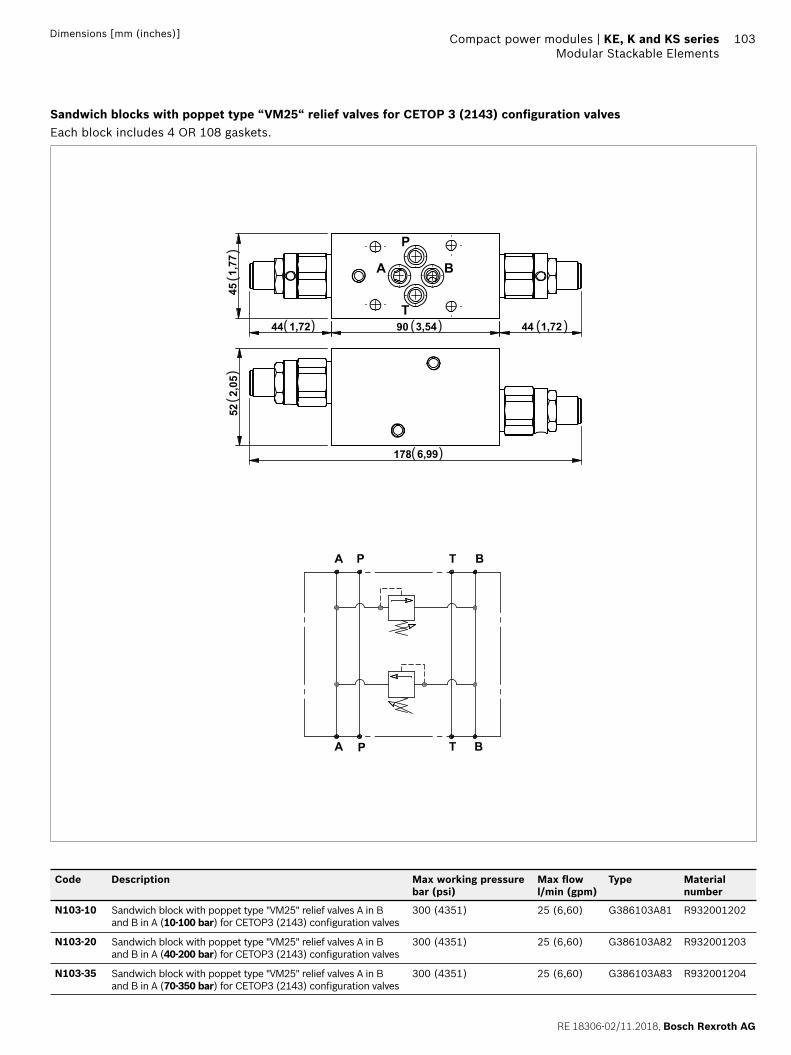
RE 18306-02/11.2018, Bosch Rexroth AG
Compact power modules | KE, K and KS series Modular Stackable Elements
103Dimensions [mm (inches)]
Sandwich blocks with poppet type “VM25“ relief valves for CETOP 3 (2143) confi guration valvesEach block includes 4 OR 108 gaskets.
451,77
44 1,72 90 3,54 44 1,72
A B
P
T
522,05
178 6,99
( ) ( )
( )
( )
()
()
A P
A P T
BT
B
Code Description Max working pressure bar (psi)
Max fl ow l/min (gpm)
Type Material number
N103-10 Sandwich block with poppet type "VM25" relief valves A in B and B in A (10-100 bar) for CETOP3 (2143) confi guration valves
300 (4351) 25 (6,60) G386103A81 R932001202
N103-20 Sandwich block with poppet type "VM25" relief valves A in B and B in A (40-200 bar) for CETOP3 (2143) confi guration valves
300 (4351) 25 (6,60) G386103A82 R932001203
N103-35 Sandwich block with poppet type "VM25" relief valves A in B and B in A (70-350 bar) for CETOP3 (2143) confi guration valves
300 (4351) 25 (6,60) G386103A83 R932001204
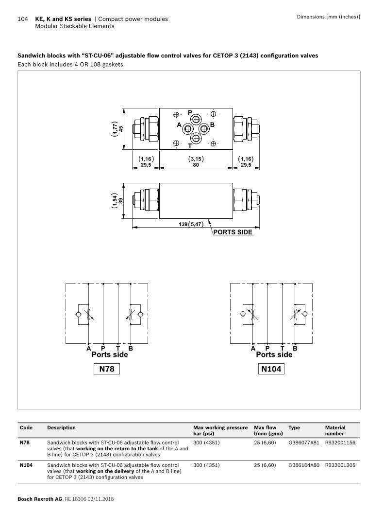
Bosch Rexroth AG, RE 18306-02/11.2018
104 KE, K and KS series | Compact power modulesModular Stackable Elements
Dimensions [mm (inches)]
Sandwich blocks with “ST-CU-06” adjustable fl ow control valves for CETOP 3 (2143) confi guration valvesEach block includes 4 OR 108 gaskets.
29,51,16
803,15
29,51,16
451,77 A B
P
T
391,54
139 5,47PORTS SIDE
( ) ( )
( )
( )
()
()
A BP TPorts side
A BP TPorts side
N78 N104
Code Description Max working pressure bar (psi)
Max fl ow l/min (gpm)
Type Material number
N78 Sandwich blocks with ST-CU-06 adjustable fl ow control valves (that working on the return to the tank of the A and B line) for CETOP 3 (2143) confi guration valves
300 (4351) 25 (6,60) G386077A81 R932001156
N104 Sandwich blocks with ST-CU-06 adjustable fl ow control valves (that working on the delivery of the A and B line) for CETOP 3 (2143) confi guration valves
300 (4351) 25 (6,60) G386104A80 R932001205
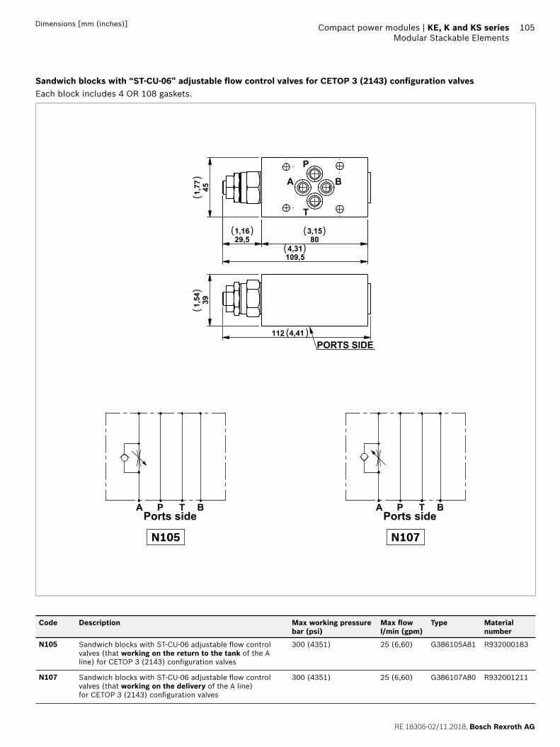
RE 18306-02/11.2018, Bosch Rexroth AG
Compact power modules | KE, K and KS series Modular Stackable Elements
105Dimensions [mm (inches)]
Sandwich blocks with “ST-CU-06” adjustable fl ow control valves for CETOP 3 (2143) confi guration valvesEach block includes 4 OR 108 gaskets.
803,15
451,77
29,51,16
109,54,31
A B
P
T391,54
112 4,41PORTS SIDE
( )
( )
( )
( )
()
()
A BP TPorts side
A BP TPorts side
N105 N107
Code Description Max working pressure bar (psi)
Max fl ow l/min (gpm)
Type Material number
N105 Sandwich blocks with ST-CU-06 adjustable fl ow control valves (that working on the return to the tank of the A line) for CETOP 3 (2143) confi guration valves
300 (4351) 25 (6,60) G386105A81 R932000183
N107 Sandwich blocks with ST-CU-06 adjustable fl ow control valves (that working on the delivery of the A line) for CETOP 3 (2143) confi guration valves
300 (4351) 25 (6,60) G386107A80 R932001211
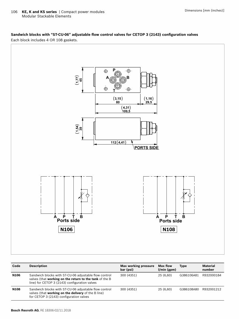
Bosch Rexroth AG, RE 18306-02/11.2018
106 KE, K and KS series | Compact power modulesModular Stackable Elements
Dimensions [mm (inches)]
Sandwich blocks with “ST-CU-06” adjustable fl ow control valves for CETOP 3 (2143) confi guration valvesEach block includes 4 OR 108 gaskets.
803,15
29,51,16
451,77
109,54,31
A B
P
T
391,54
112 4,41PORTS SIDE
( )
( )
( )
( )
()
()
A BP TPorts side
A BP TPorts side
N106 N108
Code Description Max working pressure bar (psi)
Max fl ow l/min (gpm)
Type Material number
N106 Sandwich blocks with ST-CU-06 adjustable fl ow control valves (that working on the return to the tank of the B line) for CETOP 3 (2143) confi guration valves
300 (4351) 25 (6,60) G386106A81 R932000184
N108 Sandwich blocks with ST-CU-06 adjustable fl ow control valves (that working on the delivery of the B line) for CETOP 3 (2143) confi guration valves
300 (4351) 25 (6,60) G386108A80 R932001212
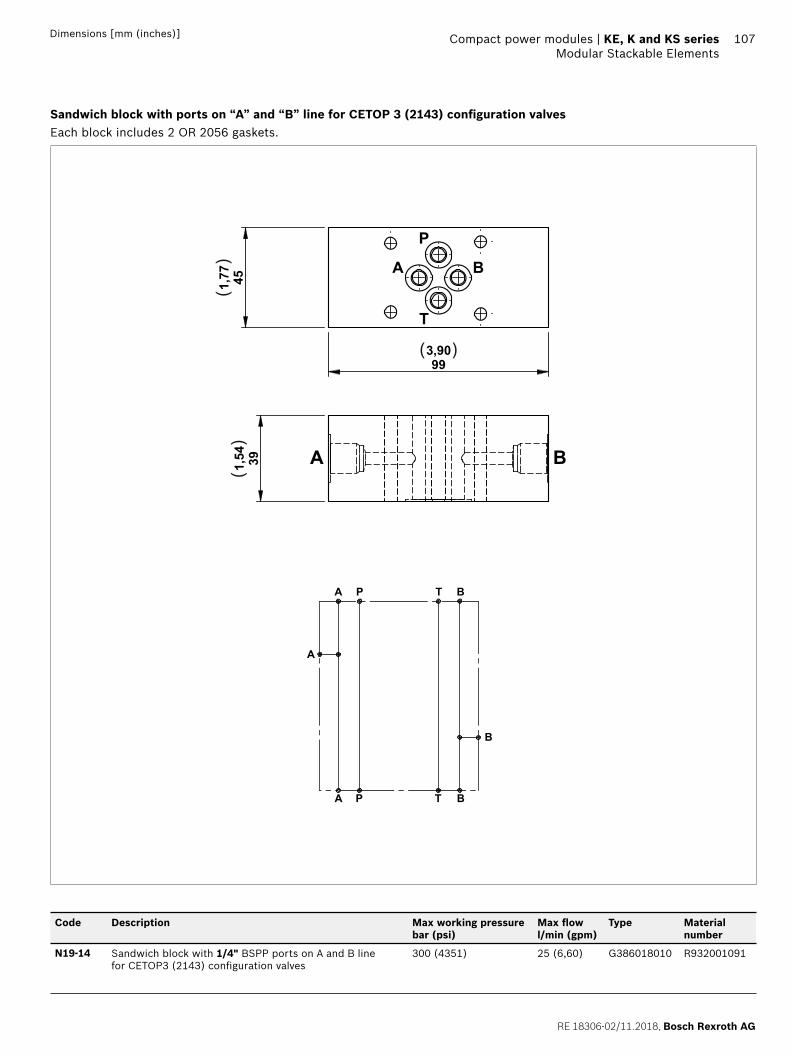
RE 18306-02/11.2018, Bosch Rexroth AG
Compact power modules | KE, K and KS series Modular Stackable Elements
107Dimensions [mm (inches)]
Sandwich block with ports on “A” and “B” line for CETOP 3 (2143) confi guration valvesEach block includes 2 OR 2056 gaskets.
BTPA
BTPA
A
B
993,90
451,77 A B
P
T
391,54 A B
( )
()
()
Code Description Max working pressure bar (psi)
Max fl ow l/min (gpm)
Type Material number
N19-14 Sandwich block with 1/4" BSPP ports on A and B line for CETOP3 (2143) confi guration valves
300 (4351) 25 (6,60) G386018010 R932001091
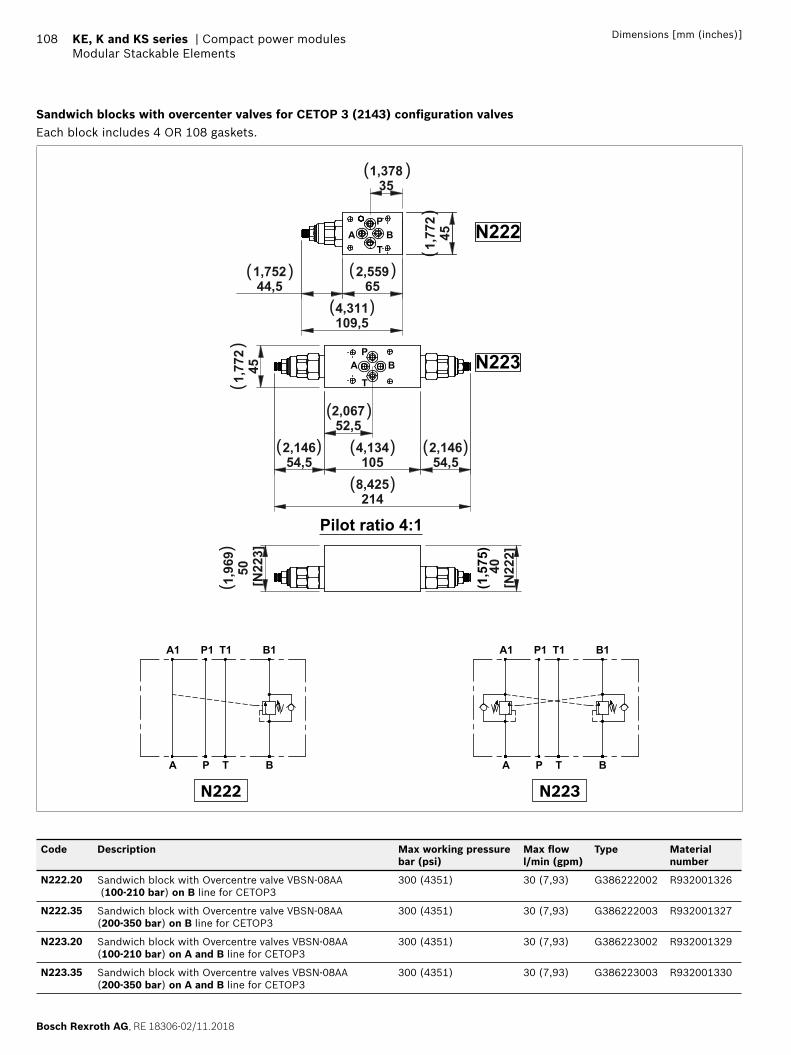
Bosch Rexroth AG, RE 18306-02/11.2018
108 KE, K and KS series | Compact power modulesModular Stackable Elements
Dimensions [mm (inches)]
Sandwich blocks with overcenter valves for CETOP 3 (2143) confi guration valvesEach block includes 4 OR 108 gaskets.
52,52,067
1054,134
54,52,146
54,52,146
451,77
2
2148,425
652,559
44,51,752
109,54,311
351,378
451,77
2
A BP
T
P
T
BA
N222
N223
50[N
223]
1,96
9
[N22
2]40
(1,5
75)
Pilot ratio 4:1
( )
( )
( )
( ) ( )( )
( )
( )
( )
()
()
()
A P T B
A1 B1T1P1
A P T B
A1 B1T1P1
N222 N223
Code Description Max working pressure bar (psi)
Max fl ow l/min (gpm)
Type Material number
N222.20 Sandwich block with Overcentre valve VBSN-08AA (100-210 bar) on B line for CETOP3
300 (4351) 30 (7,93) G386222002 R932001326
N222.35 Sandwich block with Overcentre valve VBSN-08AA (200-350 bar) on B line for CETOP3
300 (4351) 30 (7,93) G386222003 R932001327
N223.20 Sandwich block with Overcentre valves VBSN-08AA (100-210 bar) on A and B line for CETOP3
300 (4351) 30 (7,93) G386223002 R932001329
N223.35 Sandwich block with Overcentre valves VBSN-08AA (200-350 bar) on A and B line for CETOP3
300 (4351) 30 (7,93) G386223003 R932001330
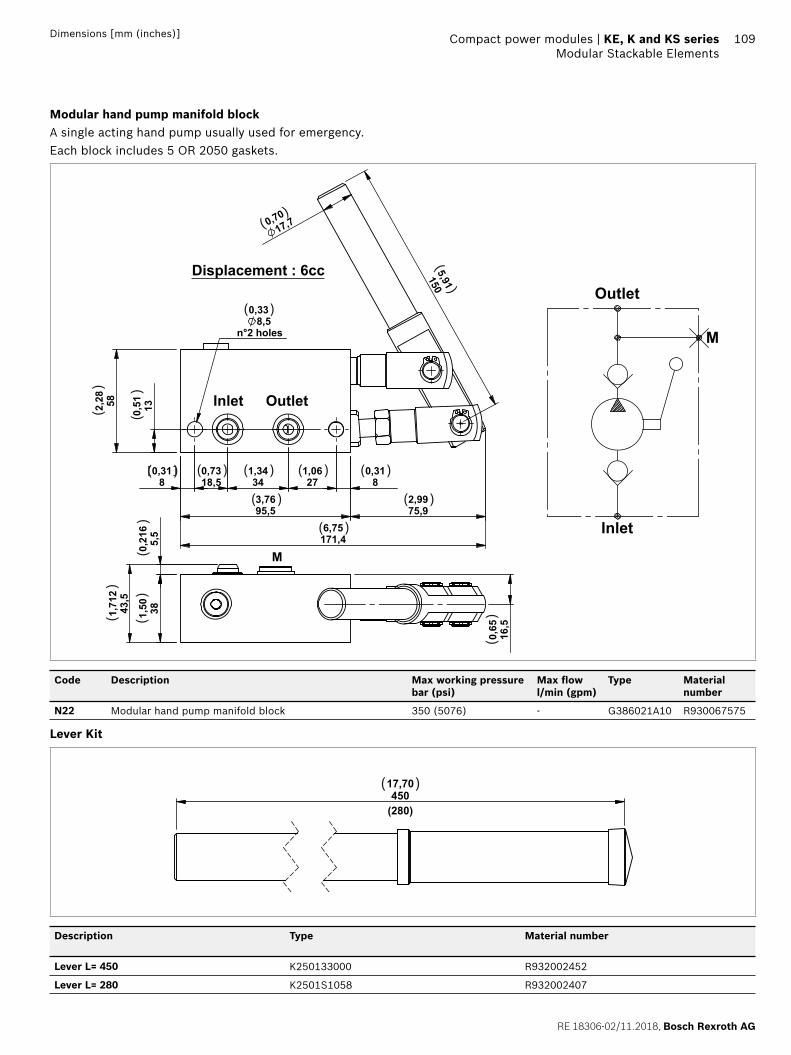
RE 18306-02/11.2018, Bosch Rexroth AG
Compact power modules | KE, K and KS series Modular Stackable Elements
109Dimensions [mm (inches)]
Modular hand pump manifold blockA single acting hand pump usually used for emergency. Each block includes 5 OR 2050 gaskets.
Displacement : 6cc
( ) ( ) ( ) ( )
( )( )
( )
()
()
()
()
()
( )
()
( )
()
()
Outlet
Inlet
M
Code Description Max working pressure bar (psi)
Max fl ow l/min (gpm)
Type Material number
N22 Modular hand pump manifold block 350 (5076) - G386021A10 R930067575
Lever Kit
45017,70
(280)
( )
Description Type Material number
Lever L= 450 K250133000 R932002452
Lever L= 280 K2501S1058 R932002407
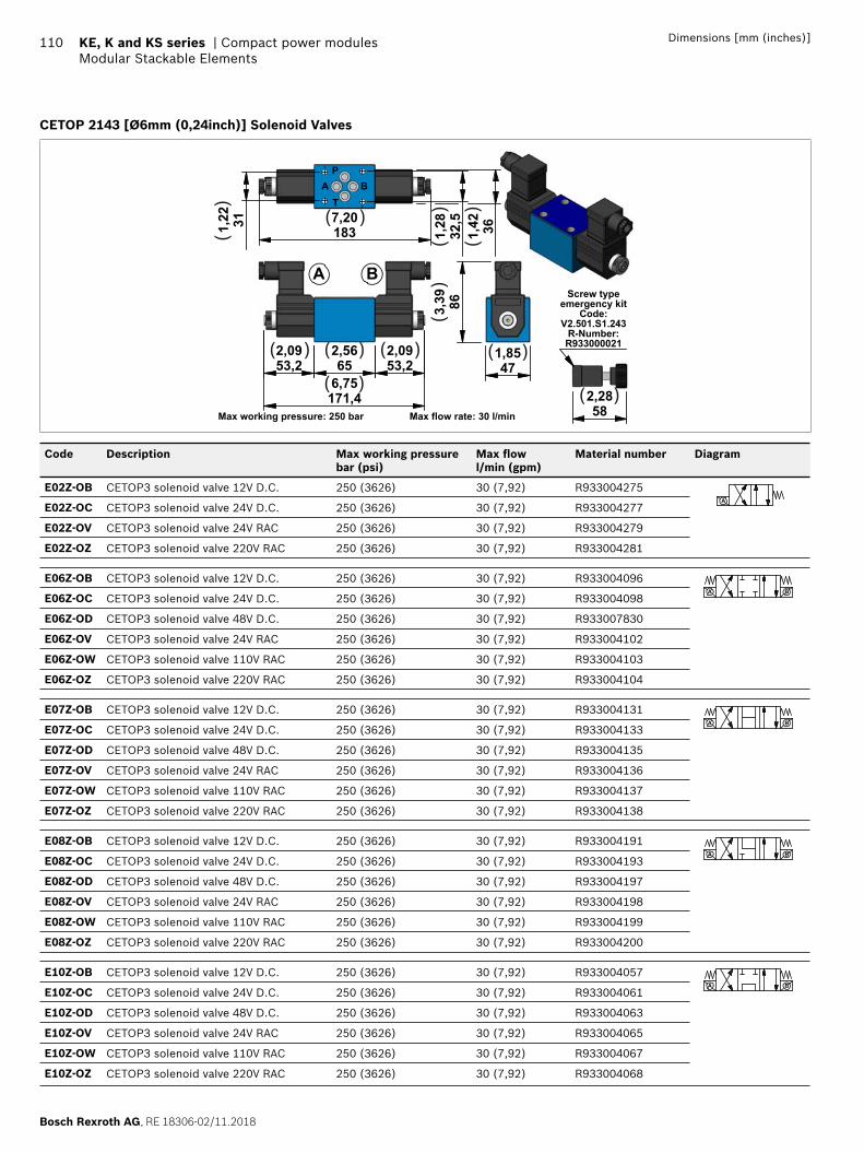
Bosch Rexroth AG, RE 18306-02/11.2018
110 KE, K and KS series | Compact power modulesModular Stackable Elements
Dimensions [mm (inches)]
CETOP 2143 [Ø6mm (0,24inch)] Solenoid Valves
582,28
Screw typeemergency kit
Code:V2.501.S1.243
R-Number:R933000021
652,56
53,22,09
53,22,09
171,46,75
A B
311,22
32,5
1,28 361,42183
7,20
AP
BT
471,85
863,39
Max working pressure: 250 bar Max flow rate: 30 l/min
( )
( )( )( )
( )( )
( )
()
()
()
()
Code Description Max working pressure bar (psi)
Max fl ow l/min (gpm)
Material number Diagram
E02Z-OB CETOP3 solenoid valve 12V D.C. 250 (3626) 30 (7,92) R933004275A
E02Z-OC CETOP3 solenoid valve 24V D.C. 250 (3626) 30 (7,92) R933004277
E02Z-OV CETOP3 solenoid valve 24V RAC 250 (3626) 30 (7,92) R933004279
E02Z-OZ CETOP3 solenoid valve 220V RAC 250 (3626) 30 (7,92) R933004281
E06Z-OB CETOP3 solenoid valve 12V D.C. 250 (3626) 30 (7,92) R933004096A B
E06Z-OC CETOP3 solenoid valve 24V D.C. 250 (3626) 30 (7,92) R933004098
E06Z-OD CETOP3 solenoid valve 48V D.C. 250 (3626) 30 (7,92) R933007830
E06Z-OV CETOP3 solenoid valve 24V RAC 250 (3626) 30 (7,92) R933004102
E06Z-OW CETOP3 solenoid valve 110V RAC 250 (3626) 30 (7,92) R933004103
E06Z-OZ CETOP3 solenoid valve 220V RAC 250 (3626) 30 (7,92) R933004104
E07Z-OB CETOP3 solenoid valve 12V D.C. 250 (3626) 30 (7,92) R933004131A B
E07Z-OC CETOP3 solenoid valve 24V D.C. 250 (3626) 30 (7,92) R933004133
E07Z-OD CETOP3 solenoid valve 48V D.C. 250 (3626) 30 (7,92) R933004135
E07Z-OV CETOP3 solenoid valve 24V RAC 250 (3626) 30 (7,92) R933004136
E07Z-OW CETOP3 solenoid valve 110V RAC 250 (3626) 30 (7,92) R933004137
E07Z-OZ CETOP3 solenoid valve 220V RAC 250 (3626) 30 (7,92) R933004138
E08Z-OB CETOP3 solenoid valve 12V D.C. 250 (3626) 30 (7,92) R933004191A B
E08Z-OC CETOP3 solenoid valve 24V D.C. 250 (3626) 30 (7,92) R933004193
E08Z-OD CETOP3 solenoid valve 48V D.C. 250 (3626) 30 (7,92) R933004197
E08Z-OV CETOP3 solenoid valve 24V RAC 250 (3626) 30 (7,92) R933004198
E08Z-OW CETOP3 solenoid valve 110V RAC 250 (3626) 30 (7,92) R933004199
E08Z-OZ CETOP3 solenoid valve 220V RAC 250 (3626) 30 (7,92) R933004200
E10Z-OB CETOP3 solenoid valve 12V D.C. 250 (3626) 30 (7,92) R933004057A B
E10Z-OC CETOP3 solenoid valve 24V D.C. 250 (3626) 30 (7,92) R933004061
E10Z-OD CETOP3 solenoid valve 48V D.C. 250 (3626) 30 (7,92) R933004063
E10Z-OV CETOP3 solenoid valve 24V RAC 250 (3626) 30 (7,92) R933004065
E10Z-OW CETOP3 solenoid valve 110V RAC 250 (3626) 30 (7,92) R933004067
E10Z-OZ CETOP3 solenoid valve 220V RAC 250 (3626) 30 (7,92) R933004068
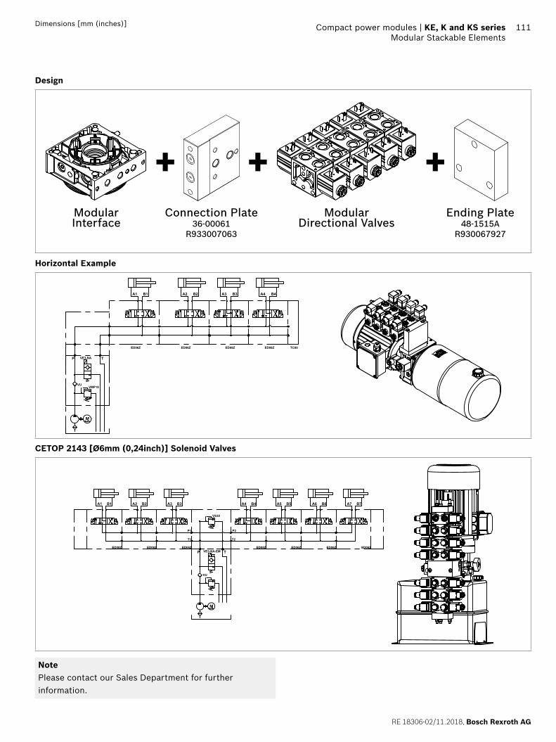
RE 18306-02/11.2018, Bosch Rexroth AG
Compact power modules | KE, K and KS series Modular Stackable Elements
111Dimensions [mm (inches)]
Design
+ + +Modular Interface
Connection Plate36-00061
R933007063
Ending Plate48-1515A
R930067927
Modular Directional Valves
Horizontal Example
VE3-NA
VUVMP18
B4A4B3A3B2A2B1A1
ED08ZED08ZED06ZED06Z
M
TP
TC00
CETOP 2143 [Ø6mm (0,24inch)] Solenoid Valves
VE3-NA-EM
VU
B7A7B6A6B5A5B4A4
ED06ZED06ZED06ZED08Z
M
VS30
T2T1
P2P1
TPED08Z ED06ZED06Z
A3 B3A2 B2A1 B1
NotePlease contact our Sales Department for further information.
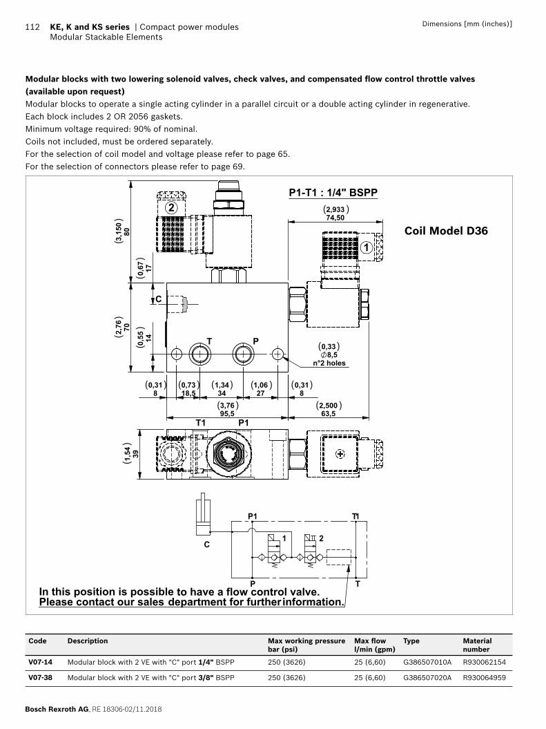
Bosch Rexroth AG, RE 18306-02/11.2018
112 KE, K and KS series | Compact power modulesModular Stackable Elements
Dimensions [mm (inches)]
Modular blocks with two lowering solenoid valves, check valves, and compensated fl ow control throttle valves (available upon request)Modular blocks to operate a single acting cylinder in a parallel circuit or a double acting cylinder in regenerative.Each block includes 2 OR 2056 gaskets.Minimum voltage required: 90% of nominal.Coils not included, must be ordered separately.For the selection of coil model and voltage please refer to page 65. For the selection of connectors please refer to page 69.
TP
C
In this position is possible to have a flow control valve.Please contact our sales department for further information.
P1
1 2
T1
14
PT
1
T1 P1
P1-T1 : 1/4" BSPP
( )
( )( )( )( )( )
( ) ( )
()
()
()
()
()
( )
Coil Model D36
Code Description Max working pressure bar (psi)
Max fl ow l/min (gpm)
Type Material number
V07-14 Modular block with 2 VE with "C" port 1/4" BSPP 250 (3626) 25 (6,60) G386507010A R930062154
V07-38 Modular block with 2 VE with "C" port 3/8" BSPP 250 (3626) 25 (6,60) G386507020A R930064959
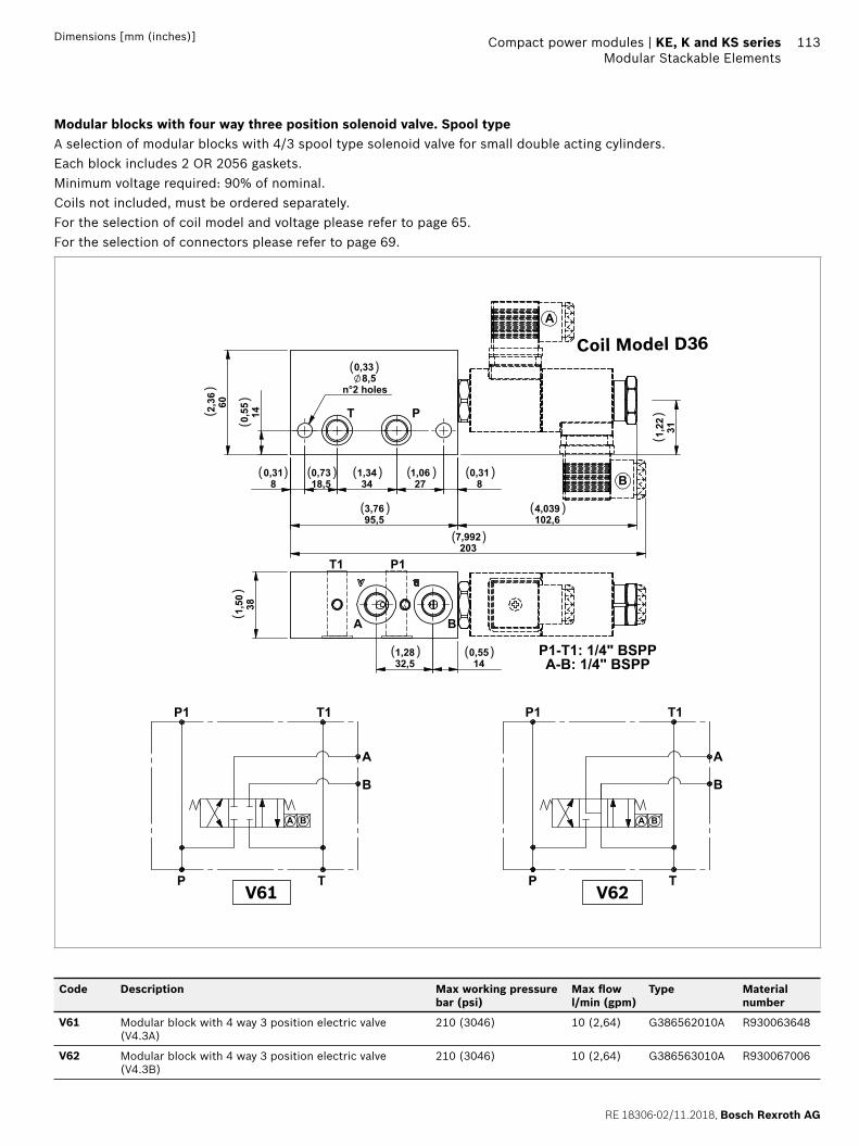
RE 18306-02/11.2018, Bosch Rexroth AG
Compact power modules | KE, K and KS series Modular Stackable Elements
113Dimensions [mm (inches)]
Modular blocks with four way three position solenoid valve. Spool typeA selection of modular blocks with 4/3 spool type solenoid valve for small double acting cylinders.Each block includes 2 OR 2056 gaskets.Minimum voltage required: 90% of nominal.Coils not included, must be ordered separately.For the selection of coil model and voltage please refer to page 65. For the selection of connectors please refer to page 69.
80,31
18,50,73
341,34
271,06
80,31
95,53,76
140,55602,
36
311,22
8,5n°2 holes
0,33
7,992203
4,039102,6
PT
A
B
381,50
32,51,28
140,55
A B
P1T1
P1-T1: 1/4" BSPPA-B: 1/4" BSPP
( )
( )( )( )( ) ( )
( )
( )
( )
( ) ( )
()
()
()
()
P1
P T
T1
A
B
A B
P1
P T
T1
A
B
A B
V62V61
Coil Model D36
Code Description Max working pressure bar (psi)
Max fl ow l/min (gpm)
Type Material number
V61 Modular block with 4 way 3 position electric valve (V4.3A)
210 (3046) 10 (2,64) G386562010A R930063648
V62 Modular block with 4 way 3 position electric valve (V4.3B)
210 (3046) 10 (2,64) G386563010A R930067006
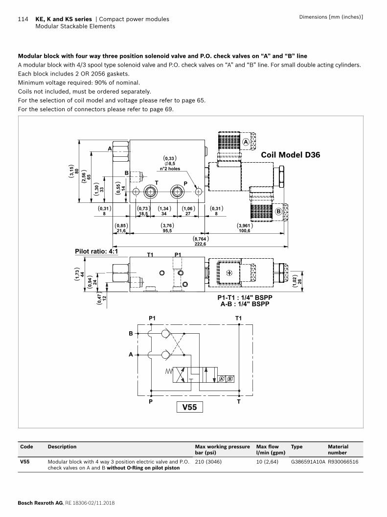
Bosch Rexroth AG, RE 18306-02/11.2018
114 KE, K and KS series | Compact power modulesModular Stackable Elements
Dimensions [mm (inches)]
Modular block with four way three position solenoid valve and P.O. check valves on “A” and “B” lineA modular block with 4/3 spool type solenoid valve and P.O. check valves on “A” and “B” line. For small double acting cylinders.Each block includes 2 OR 2056 gaskets.Minimum voltage required: 90% of nominal.Coils not included, must be ordered separately.For the selection of coil model and voltage please refer to page 65. For the selection of connectors please refer to page 69.
44
P1
14
P
Pilot ratio: 4:1
( )
( )
( )( )( )( )
( ) ( ) ( )
( )
()
()
()
()
()
()
()
()
A
B
P T
P1 T1
A B
V55
Coil Model D36
Code Description Max working pressure bar (psi)
Max fl ow l/min (gpm)
Type Material number
V55 Modular block with 4 way 3 position electric valve and P.O. check valves on A and B without O-Ring on pilot piston
210 (3046) 10 (2,64) G386591A10A R930066516
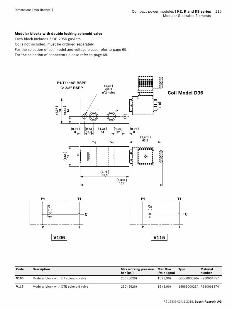
RE 18306-02/11.2018, Bosch Rexroth AG
Compact power modules | KE, K and KS series Modular Stackable Elements
115Dimensions [mm (inches)]
Modular blocks with double locking solenoid valveEach block includes 2 OR 2056 gaskets.Coils not included, must be ordered separately.For the selection of coil model and voltage please refer to page 65. For the selection of connectors please refer to page 69.
8 34 8
14 T P
T1 P1
C
P1-T1: 1/4" BSPPC: 3/8" BSPP
( )( )( )
( )
( )( )
()
()
()
( )
( )
( )
C
P1 T1
P T
C
P1 T1
P T
V115V106
Coil Model D36
Code Description Max working pressure bar (psi)
Max fl ow l/min (gpm)
Type Material number
V106 Modular block with DT solenoid valve 250 (3626) 15 (3,96) G386606020A R930064757
V115 Modular block with DTE solenoid valve 250 (3626) 15 (3,96) 1586500023A R930061374
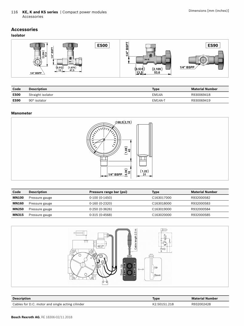
Bosch Rexroth AG, RE 18306-02/11.2018
116 KE, K and KS series | Compact power modulesAccessories
Dimensions [mm (inches)]
AccessoriesIsolator
1/4
" B
SPT
0,512
13 1,87047,5
1/4" BSPP
2,
264
57,5
( ) ( )
()
ES00 ES90
1/4
" B
SPT
0,53113,5
2,10953,6
( ) ( ) 1/4" BSPP
Code Description Type Material Number
ES00 Straight isolator EM14A R930069418
ES90 90° isolator EM14A-T R930069419
Manometer
431,69
100,39
68,5 2,70
1/4" BSPP 311,22
( )
( )
()
()
Code Description Pressure range bar (psi) Type Material Number
MN100 Pressure gauge 0-100 (0-1450) C163017000 R932000582
MN160 Pressure gauge 0-160 (0-2320) C163018000 R932000583
MN250 Pressure gauge 0-250 (0-3626) C163019000 R932000584
MN315 Pressure gauge 0-315 (0-4568) C163020000 R932000585
Description Type Material Number
Cables for D.C. motor and single acting cilinder K2.501S1.218 R932002428
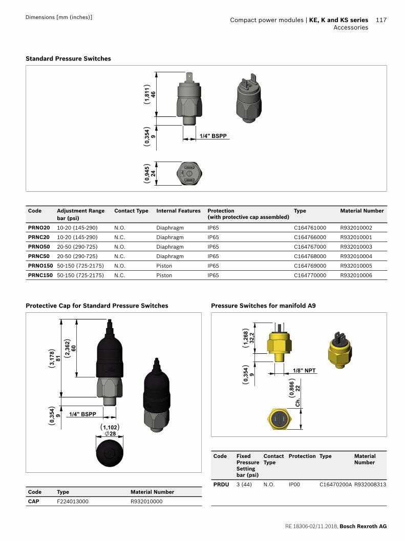
RE 18306-02/11.2018, Bosch Rexroth AG
Compact power modules | KE, K and KS series Accessories
117Dimensions [mm (inches)]
Standard Pressure Switches
90,
354
461,81
1
1/4" BSPP
240,94
5(
)(
)(
)
Code Adjustment Range bar (psi)
Contact Type Internal Features Protection(with protective cap assembled)
Type Material Number
PRNO20 10-20 (145-290) N.O. Diaphragm IP65 C164761000 R932010002
PRNC20 10-20 (145-290) N.C. Diaphragm IP65 C164766000 R932010001
PRNO50 20-50 (290-725) N.O. Diaphragm IP65 C164767000 R932010003
PRNC50 20-50 (290-725) N.C. Diaphragm IP65 C164768000 R932010004
PRNO150 50-150 (725-2175) N.O. Piston IP65 C164769000 R932010005
PRNC150 50-150 (725-2175) N.C. Piston IP65 C164770000 R932010006
Protective Cap for Standard Pressure Switches
90,
354
1/4" BSPP
813,17
8 602,36
2
281,102( )
()
()
()
Code Type Material Number
CAP F224013000 R932010000
Pressure Switches for manifold A9
1/8" NPT
0,
354
9
1,
268
32,2
Ch.
0,86
622
()(
)(
)
Code Fixed Pressure Setting bar (psi)
Contact Type
Protection Type Material Number
PRDU 3 (44) N.O. IP00 C16470200A R932008313
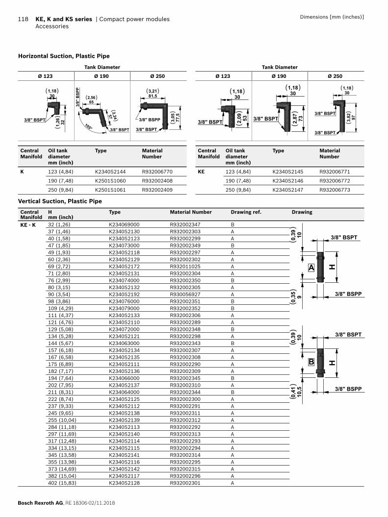
Bosch Rexroth AG, RE 18306-02/11.2018
118 KE, K and KS series | Compact power modulesAccessories
Dimensions [mm (inches)]
Horizontal Suction, Plastic Pipe
Tank Diameter
Ø 123 Ø 190 Ø 250
301,18
321,263/8" BSPT
( )
()
105°
652,56
572,24
3/8" BSPT
3/8"
BSP
P
( )
()
81,53,21
77,5
3,05
3/8" BSPT
3/8" BSPP
( )
()
Central Manifold
Oil tank diametermm (inch)
Type MaterialNumber
K 123 (4,84) K2340S2144 R932006770
190 (7,48) K2501S1060 R932002408
250 (9,84) K2501S1061 R932002409
Tank Diameter
Ø 123 Ø 190 Ø 250
301,18
532,09
3/8" BSPT
( )
()
301,18
732,873/8" BSPT
( )
()
301,18
973,82
3/8" BSPT
3/8" BSPT
( )
()
Central Manifold
Oil tank diametermm (inch)
Type MaterialNumber
KE 123 (4,84) K2340S2145 R932006771
190 (7,48) K2340S2146 R932006772
250 (9,84) K2340S2147 R932006773
Vertical Suction, Plastic Pipe
Central Manifold
Hmm (inch)
Type Material Number Drawing ref. Drawing
KE - K 32 (1,26) K234069000 R932002347 B
3/8" BSPT
3/8" BSPP
3/8" BSPP
3/8" BSPTH
H
100,39
90,35
10,5
0,41
100,39
A
B
()
()
()
()
37 (1,46) K2340S2130 R932002303 A40 (1,58) K2340S2123 R932002299 A47 (1,85) K234073000 R932002349 B49 (1,93) K2340S2118 R932002297 A60 (2,36) K2340S2129 R932002302 A69 (2,72) K2340S2172 R932011025 A71 (2,80) K2340S2131 R932002304 A76 (2,99) K234074000 R932002350 B80 (3,15) K2340S2132 R932002305 A90 (3,54) K2340S2192 R930056927 A98 (3,86) K234076000 R932002351 B109 (4,29) K234079000 R932002352 B111 (4,37) K2340S2133 R932002306 A121 (4,76) K2340S2110 R932002289 A129 (5,08) K234072000 R932002348 B134 (5,28) K2340S2121 R932002298 A144 (5,67) K234063000 R932002343 B157 (6,18) K2340S2134 R932002307 A167 (6,58) K2340S2135 R932002308 A175 (6,89) K2340S2111 R932002290 A182 (7,17) K2340S2136 R932002309 A194 (7,64) K234066000 R932002345 B202 (7,95) K2340S2137 R932002310 A211 (8,31) K234064000 R932002344 B222 (8,74) K2340S2125 R932002300 A237 (9,33) K2340S2112 R932002291 A245 (9,65) K2340S2138 R932002311 A255 (10,04) K2340S2139 R932002312 A284 (11,18) K2340S2113 R932002292 A297 (11,69) K2340S2140 R932002313 A317 (12,48) K2340S2114 R932002293 A334 (13,15) K2340S2115 R932002294 A345 (13,58) K2340S2141 R932002314 A355 (13,98) K2340S2116 R932002295 A373 (14,69) K2340S2142 R932002315 A382 (15,04) K2340S2117 R932002296 A402 (15,83) K2340S2128 R932002301 A
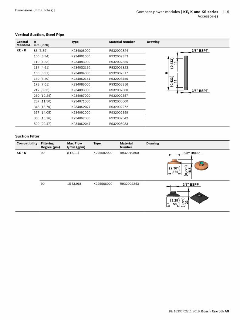
RE 18306-02/11.2018, Bosch Rexroth AG
Compact power modules | KE, K and KS series Accessories
119Dimensions [mm (inches)]
Vertical Suction, Steel Pipe
Central Manifold
Hmm (inch)
Type Material Number Drawing
KE - K 86 (3,39) K234006000 R932009324
H
3/8" BSPT
3/8" BSPT
110,43
3110,43
3(
)(
)
100 (3,94) K234081000 R932002353
110 (4,33) K234083000 R932002355
117 (4,61) K2340S2162 R932009323
150 (5,91) K234004000 R932002317
160 (6,30) K2340S2151 R932008456
178 (7,01) K234086000 R932002356
212 (8,35) K234093000 R932002360
260 (10,24) K234087000 R932002357
287 (11,30) K234071000 R932006600
348 (13,70) K2340S2027 R932002272
357 (14,05) K234092000 R932002359
385 (15,16) K234062000 R932002342
520 (20,47) K2340S2047 R932008033
Suction Filter
Compatibility Filtering Degree (µm)
Max Flowl/min (gpm)
Type MaterialNumber
Drawing
KE - K 90 8 (2,11) K225582000 R932010860 3/8" BSPP
602,361
18,5
0,72
8( )
()
90 15 (3,96) K225566000 R932002243
582,28
230,91
3/8" BSPP
( )
()
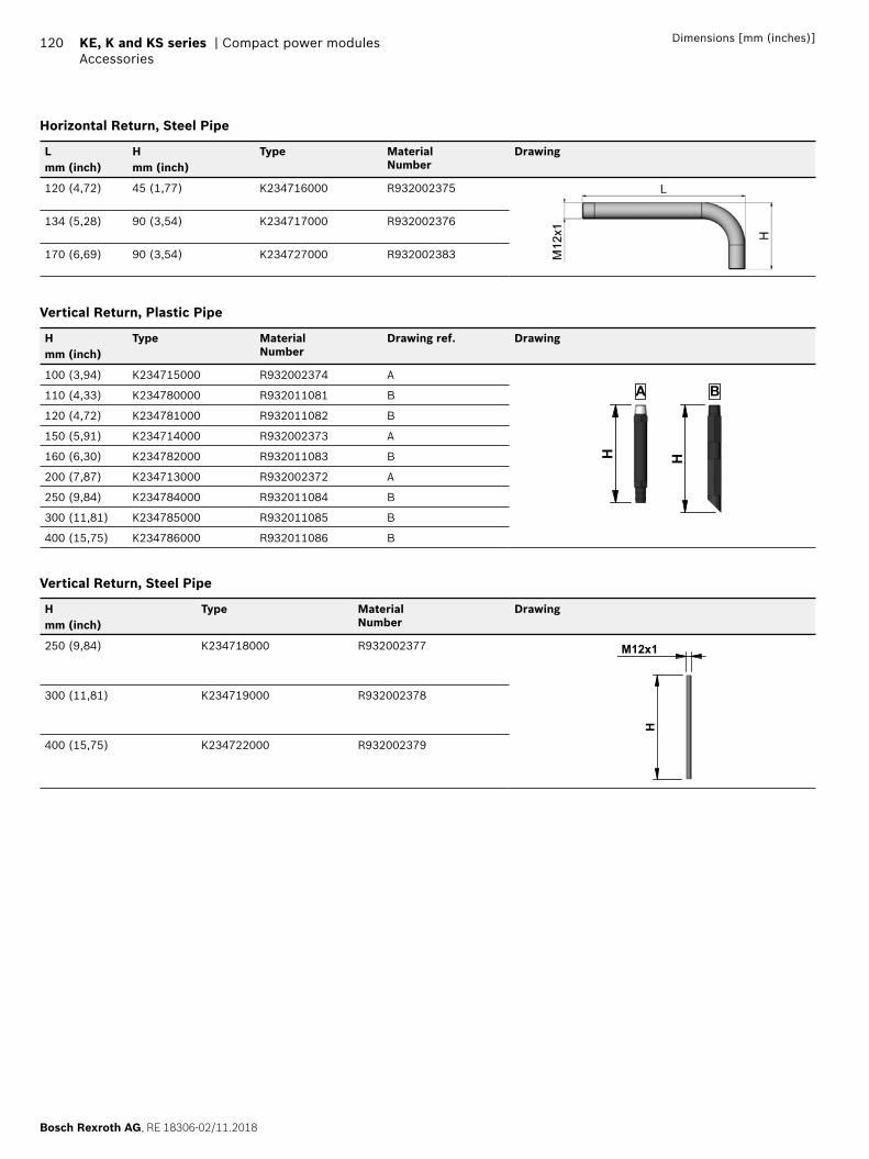
Bosch Rexroth AG, RE 18306-02/11.2018
120 KE, K and KS series | Compact power modulesAccessories
Dimensions [mm (inches)]
Horizontal Return, Steel Pipe
Lmm (inch)
Hmm (inch)
Type MaterialNumber
Drawing
120 (4,72) 45 (1,77) K234716000 R932002375
134 (5,28) 90 (3,54) K234717000 R932002376
170 (6,69) 90 (3,54) K234727000 R932002383
Vertical Return, Plastic Pipe
Hmm (inch)
Type MaterialNumber
Drawing ref. Drawing
100 (3,94) K234715000 R932002374 A
H H
A B110 (4,33) K234780000 R932011081 B
120 (4,72) K234781000 R932011082 B
150 (5,91) K234714000 R932002373 A
160 (6,30) K234782000 R932011083 B
200 (7,87) K234713000 R932002372 A
250 (9,84) K234784000 R932011084 B
300 (11,81) K234785000 R932011085 B
400 (15,75) K234786000 R932011086 B
Vertical Return, Steel Pipe
Hmm (inch)
Type MaterialNumber
Drawing
250 (9,84) K234718000 R932002377H
M12x1
300 (11,81) K234719000 R932002378
400 (15,75) K234722000 R932002379

RE 18306-02/11.2018, Bosch Rexroth AG
Compact power modules | KE, K and KS series Accessories
121
122
Bosch Rexroth AG, RE 18306-02/11.2018
Bosch Rexroth Oil Control S.p.A.Oil Sistem DivisionVia Artigianale Sedrio, 1242030 Vezzano sul CrostoloReggio Emilia - ItalyTel. +39 0522 601 801Fax +39 0522 606 226 / 601 [email protected]/compacthydraulics
© This document, as well as the data, specifi cations and other information set forth in it, are the exclusive property of Bosch Rexroth Oil Control S.p.a.. It may not be reproduced or given to third parties without its consent.The data specifi ed above only serve to describe the product. No statements concerning a certain condition or suitability for a certain application can be derived from our information. The information given does not release the user from the obligation of own judgment and verifi cation. It must be remembered that our products are subject to a natural process of wear and aging.Subject to change.


![Ks/ r í õ s /E D/E/^dZ d/KE Z KZ...Ks/ r í õ s /E D/E/^dZ d/KE Z KZ Ks/ r í õ s ] v u ] v ] ] } v Z } W P î } ( î s ] } v í î r í ò r î ì î ì 2IILFH 8VH 2QO\ 6(&7,21](https://img.pdfslide.us/doc/110x75/60b4bdfb7906fc3dfb3bc701/ks-r-s-e-dedz-dke-z-kz-ks-r-s-e-dedz-dke-z-kz-ks-r.jpg)


![] s v ( ( ] D ] o v Ks/ r í õ d o Z o Z ^ µ } ' } µ t } l Z€¦ · ^ ^^/KE í W 'ZKhW /EdZK h d/KE Ks/ r í õ & d^ s^ X &/ d/KE 'K >^ W o ] Z ] v } µ ] } v U À ] Á P } µ](https://img.pdfslide.us/doc/110x75/6059b5424ba9bd2e9751e6a7/-s-v-d-o-v-ks-r-d-o-z-o-z-t-l-z-ke-w-zkhw.jpg)


![Zakir Naik ke Non-Muslims ke 20 sawalon ke jawab [hindi]](https://img.pdfslide.us/doc/110x75/577d26f31a28ab4e1ea2a1ca/zakir-naik-ke-non-muslims-ke-20-sawalon-ke-jawab-hindi.jpg)

![K^d Z Ks Zz /DW> D Ed d/KE ^d d D Ed o ] ] } v ( } P } À](https://img.pdfslide.us/doc/110x75/62919e47f713036ca2502d90/kd-z-ks-zz-dwgt-d-ed-dke-d-d-d-ed-o-v-p-.jpg)