Embed Size (px)
Citation preview
9
9.151Subject to change
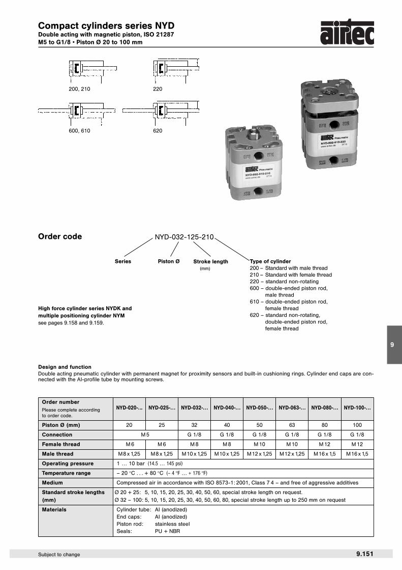
Compact cylinders series NYDDouble acting with magnetic piston, ISO 21287M5 to G1/8 • Piston Ø 20 to 100 mm
Order numberNYD-020-. .. NYD-025-. . . NYD-032-. . . NYD-040-. . . NYD-050-. . . NYD-063-. . . NYD-080-. . . NYD-100-. . .Please complete according
to order code.
Piston Ø (mm) 20 25 32 40 50 63 80 100
Connection M 5 G 1/8 G 1/8 G 1/8 G 1/8 G 1/8 G 1/8
Female thread M 6 M 6 M 8 M 8 M 10 M 10 M 12 M 12
Male thread M8 x 1,25 M8 x 1,25 M10 x 1,25 M10 x 1,25 M12 x 1,25 M12 x 1,25 M16 x 1,5 M16 x 1,5
Operating pressure 1 … 10 bar (14.5 … 145 psi)
Temperature range – 20 °C . . . + 80 °C (– 4 °F … + 176 °F)
Medium Compressed air in accordance with ISO 8573-1: 2001, Class 7 4 – and free of aggressive additives
Standard stroke lengths Ø 20 + 25: 5, 10, 15, 20, 25, 30, 40, 50, 60, special stroke length on request.
(mm) Ø 32 – 100: 5, 10, 15, 20, 25, 30, 40, 50, 60, 80, special stroke length up to 250 mm on request
Materials Cylinder tube: Al (anodized)End caps: Al (anodized)Piston rod: stainless steelSeals: PU + NBR
Order code NYD-032-125-210
Series Piston Ø Stroke length(mm)
Type of cylinder200 – Standard with male thread210 – Standard with female thread220 – standard non-rotating600 – double-ended piston rod,
male thread610 – double-ended piston rod,
female thread620 – standard non-rotating,
double-ended piston rod,female thread
Design and functionDouble acting pneumatic cylinder with permanent magnet for proximity sensors and built-in cushioning rings. Cylinder end caps are con-nected with the Al-profile tube by mounting screws.
200, 210 220
600, 610 620
High force cylinder series NYDK andmultiple positioning cylinder NYMsee pages 9.158 and 9.159.

9.152 Subject to change
Loading diagram for compact cylinders series NYDDouble acting with magnetic piston, ISO 21287M5 to G1/8 • Piston Ø 20 to 100 mm
Series NYD (Type for order code: –200 = male thread, –210 = female thread)
Series NYD (Type for order code: –220 = non-rotating)

9
9.153Subject to change
Loading diagram for compact cylinders series NYDDouble acting with magnetic piston, ISO 21287M5 to G1/8 • Piston Ø 20 to 100 mm
Series NYD (Type for order code: –600 = male thread, –610 = female thread)
Series NYD (Type for order code: –620 = non-rotating)

9.154 Subject to change
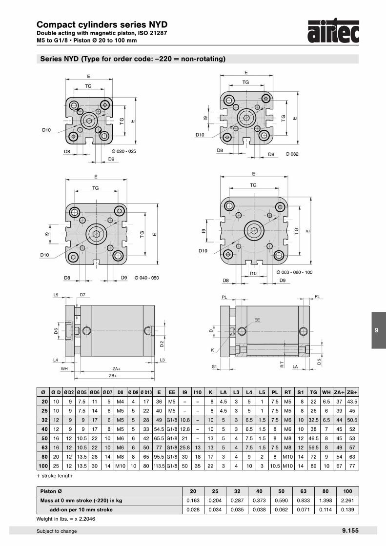
Compact cylinders series NYDDouble acting with magnetic piston, ISO 21287M5 to G1/8 • Piston Ø 20 to 100 mm
Ø A AF Ø D Ø D2 Ø D5 E EE I9 I10 K KF KK LA L3 PL RT TG WH ZA+ ZB+
20 16 15 10 9 7.5 36 M5 – – 8 M6 M8 4.5 3 7.5 M5 22 6.5 37 43.5
25 16 15 10 9 7.5 40 M5 – – 8 M6 M8 4.5 3 7.5 M5 26 6 39 45
32 19 16 12 9 9 49 G1/8 10.8 – 10 M8 M10 x 1.25 5 3 7.5 M6 32.5 6.5 44 50.5
40 19 16 12 9 9 54.5 G1/8 12.8 – 10 M8 M10 x 1.25 5 3 8 M6 38 7 45 52
50 22 17 16 12 10.5 65.5 G1/8 21 – 13 M10 M12 x 1.25 5 4 8 M8 46.5 8 45 53
63 22 17 16 12 10.5 77 G1/8 25.8 13 13 M10 M12 x 1.25 5 4 7.5 M8 56.5 8 49 57
80 28 20 20 12 13.5 95.5 G1/8 30 18 17 M12 M16 x 1.5 3 4 8 M10 72 9 54 63
100 28 20 25 12 13.5 113.5 G1/8 50 35 22 M12 M16 x 1.5 3 4 10.5 M10 89 10 67 77
Series NYD (Type for order code: –200 = male thread, –210 = female thread)
+ stroke length
Piston Ø 20 25 32 40 50 63 80 100
Mass at 0 mm stroke (-210) in kg 0.131 0.166 0.217 0.278 0.435 0.625 0.996 1.722
Mass at 0 mm stroke (-200) in kg 0.143 0.178 0.240 0.301 0.471 0.661 1.066 1.793
add-on per 10 mm stroke 0.024 0.028 0.029 0.030 0.048 0.057 0.088 0.115
Weight in lbs. = x 2.2046
9
9.155Subject to change
Compact cylinders series NYDDouble acting with magnetic piston, ISO 21287M5 to G1/8 • Piston Ø 20 to 100 mm
Ø Ø D Ø D2 Ø D5 Ø D6 Ø D7 D8 Ø D9 Ø D10 E EE I9 I10 K LA L3 L4 L5 PL RT S1 TG WH ZA+ ZB+
20 10 9 7.5 11 5 M4 4 17 36 M5 – – 8 4.5 3 5 1 7.5 M5 8 22 6.5 37 43.5
25 10 9 7.5 14 6 M5 5 22 40 M5 – – 8 4.5 3 5 1 7.5 M5 8 26 6 39 45
32 12 9 9 17 6 M5 5 28 49 G1/8 10.8 – 10 5 3 6.5 1.5 7.5 M6 10 32.5 6.5 44 50.5
40 12 9 9 17 8 M5 5 33 54.5 G1/8 12.8 – 10 5 3 6.5 1.5 8 M6 10 38 7 45 52
50 16 12 10.5 22 10 M6 6 42 65.5 G1/8 21 – 13 5 4 7.5 1.5 8 M8 12 46.5 8 45 53
63 16 12 10.5 22 10 M6 6 50 77 G1/8 25.8 13 13 5 4 7.5 1.5 7.5 M8 12 56.5 8 49 57
80 20 12 13.5 28 14 M8 8 65 95.5 G1/8 30 18 17 3 4 9 2 8 M10 14 72 9 54 63
100 25 12 13.5 30 14 M10 10 80 113.5 G1/8 50 35 22 3 4 10 3 10.5 M10 14 89 10 67 77
Series NYD (Type for order code: –220 = non-rotating)
+ stroke length
Piston Ø 20 25 32 40 50 63 80 100
Mass at 0 mm stroke (-220) in kg 0.163 0.204 0.287 0.373 0.590 0.833 1.398 2.261
add-on per 10 mm stroke 0.028 0.034 0.035 0.038 0.062 0.071 0.114 0.139
Weight in lbs. = x 2.2046

9.156 Subject to change
Compact cylinders series NYDDouble acting with magnetic piston, ISO 21287M5 to G1/8 • Piston Ø 20 to 100 mm
Ø A AF Ø D Ø D5 E EE I9 I10 K KF KK LA PL RT TG WH WH+ ZA+ ZB+
20 16 15 10 7.5 36 M5 – – 8 M6 M8 4.5 7.5 M5 22 6.5 6.5 37 43.5
25 16 15 10 7.5 40 M5 – – 8 M6 M8 4.5 7.5 M5 26 6 6 39 45
32 19 16 12 9 49 G1/8 10.8 – 10 M8 M10 x 1.25 5 7.5 M6 32.5 6.5 6.5 44 50.5
40 19 16 12 9 54.5 G1/8 12.8 – 10 M8 M10 x 1.25 5 8 M6 38 7 7 45 52
50 22 17 16 10.5 65.5 G1/8 21 – 13 M10 M12 x 1.25 5 8 M8 46.5 8 8 45 53
63 22 17 16 10.5 77 G1/8 25.8 13 13 M10 M12 x 1.25 5 7.5 M8 56.5 8 8 49 57
80 28 20 20 13.5 95.5 G1/8 30 18 17 M12 M16 x 1.5 3 8 M10 72 9 9 54 63
100 28 20 25 13.5 113.5 G1/8 50 35 22 M12 M16 x 1.5 3 10.5 M10 89 10 10 67 77
Series NYD (Type for order code: –600 = male thread, –610 = female thread)
+ stroke length
Piston Ø 20 25 32 40 50 63 80 100
Mass at 0 mm stroke (-610) in kg 0.140 0.175 0.232 0.293 0.463 0.653 1.050 1.833
Mass at 0 mm stroke (-600) in kg 0.164 0.199 0.278 0.339 0.535 0.725 1.190 1.975
add-on per 10 mm stroke 0.030 0.034 0.037 0.038 0.064 0.073 0.114 0.149
Weight in lbs. = x 2.2046

9
9.157Subject to change
Compact cylinders series NYDDouble acting with magnetic piston, ISO 21287M5 to G1/8 • Piston Ø 20 to 100 mm
Ø A AF Ø D Ø D5 Ø D6 Ø D7 D8 Ø D9 Ø D10 E EE I9 I10 K KF KK LA L4 L5 PL RT S1 TG WH WH+ ZA+ ZB+
20 16 15 10 7.5 11 5 M4 4 17 36 M5 – – 8 M6 M8 4.5 5 1 7.5 M5 8 22 6.5 6.5 37 43.5
25 16 15 10 7.5 14 6 M5 5 22 40 M5 – – 8 M6 M8 4.5 5 1 7.5 M5 8 26 6 6 39 45
32 19 16 12 9 17 6 M5 5 28 49 G1/8 10.8 – 10 M8 M10x1.25 5 6.5 1.5 7.5 M6 10 32.5 6.5 6.5 44 50.5
40 19 16 12 9 17 8 M5 5 33 54.5 G1/8 12.8 – 10 M8 M10x1.25 5 6.5 1.5 8 M6 10 38 7 7 45 52
50 22 17 16 10.5 22 10 M6 6 42 65.5 G1/8 21 – 13 M10 M12x1.25 5 7.5 1.5 8 M8 12 46.5 8 8 45 53
63 22 17 16 10.5 22 10 M6 6 50 77 G1/8 25.8 13 13 M10 M12x1.25 5 7.5 1.5 7.5 M8 12 56.5 8 8 49 57
80 28 20 20 13.5 28 14 M8 8 65 95.5 G1/8 30 18 17 M12 M16x1.5 3 9 2 8 M10 14 72 9 9 54 63
100 28 20 25 13.5 30 14 M10 10 80 113.5 G1/8 50 35 22 M12 M16x1.5 3 10 3 10.5 M10 14 89 10 10 67 77
Series NYD (Type for order code: –620 = non-rotating)
+ stroke length
Piston Ø 20 25 32 40 50 63 80 100
Mass at 0 mm stroke (-620) in kg 0.172 0.213 0.302 0.388 0.618 0.861 1.452 2.372
add-on per 10 mm stroke 0.034 0.040 0.043 0.046 0.078 0.087 0.140 0.173
Weight in lbs. = x 2.2046

High force cylinder series NYDKDouble acting with magnetic piston, similar to ISO 21287M5 to G1/8 • Piston Ø 20 to 100 mm
9.158 Subject to change
+ stroke length
Order code
NYDK2-025-050-210
SeriesNYDK2 = 2 x forceNYDK3 = 3 x forceNYDK4 = 4 x force
Piston Ø Stroke length(mm)
Type for order code200 – Standard with male thread210 – Standard with female thread
NYDK2 NYDK3
NYDK4
Series and functionMultiplying the force will be achieved by adding several cylinders with same diameter and same stroke length.
For cylinder applications for NYDK3and NYDK4 please check mountingadvises with our technical depart-ment.
NYDK2
NYDK3
Piston Ø 20 25 32 40 50 63 80 100
NYDK2 Mass at 0 mm stroke (-210) in kg 0.274 0.339 0.457 0.574 0.852 1.242 2.066 3.534
NYDK2 Mass at 0 mm stroke (-200) in kg 0.286 0.351 0.480 0.597 0.888 1.278 2.136 3.605
add on for 1 x NYDK3 and 2 x NYDK4 0.143 0.173 0.240 0.296 0.417 0.617 1.070 1.812
add-on for each 10 mm stroke (total of all cyl. elements) 0.024 0.028 0.029 0.030 0.048 0.057 0.088 0.115
Ø A AF Ø D Ø D2 Ø D5 E EE K KF KK L3 LA PL RT TG WH ZA+
20 16 15 10 9 7.5 36 M5 8 M6 M8 3 4.5 7.5 M5 22 6.5 37
25 16 15 10 9 7.5 40 M5 8 M6 M8 3 4.5 7.5 M5 26 6 39
32 19 16 12 9 9 49 G1/8 10 M8 M10 x 1.25 3 5 7.5 M6 32.5 6.5 44
40 19 16 12 9 9 54.5 G1/8 10 M8 M10 x 1.25 3 5 8 M6 38 7 45
50 22 17 16 12 10.5 65.5 G1/8 13 M10 M12 x 1.25 4 5 8 M8 46.5 8 45
63 22 17 16 12 10.5 77 G1/8 13 M10 M12 x 1.25 4 5 7.5 M8 56.5 8 49
80 28 20 20 12 13.5 95.5 G1/8 17 M12 M16 x 1.5 4 3 8 M10 72 9 54
100 28 20 25 12 13.5 113.5 G1/8 22 M12 M16 x 1.5 4 3 10.5 M10 89 10 67
Weight in lbs. = x 2.2046

9
Multiple positioning cylinder series NYMDouble acting with magnetic piston, similar to ISO 21287M5 to G1/8 • Piston Ø 20 to 100 mm
Rod threadIG – female threadAG – male thread
+ stroke length
Order code
NYM2IG-025-000000
Series Piston Ø3 positions
NYM2
NYM3
stroke1 stroke2
NYM3IG-025-000000000
Series 4 positions stroke1 stroke2 stroke3
9.159Subject to change
NYM2
NYM3
Series and functionCombining 2 to 3 cylinders with same piston diameter but different stroke lengths provides a max. of 4* positions.
* More positions on request.
stroke 1 < stroke 2 < stroke 3 …
The max. single stroke is equal tothe max. total stroke.
Ø A AF Ø D Ø D2 Ø D5 E EE K KF KK L3 LA PL RT TG WH ZA+
20 16 15 10 9 7.5 36 M5 8 M6 M8 3 4.5 7.5 M5 22 6.5 37
25 16 15 10 9 7.5 40 M5 8 M6 M8 3 4.5 7.5 M5 26 6 39
32 19 16 12 9 9 49 G1/8 10 M8 M10 x 1.25 3 5 7.5 M6 32.5 6.5 44
40 19 16 12 9 9 54.5 G1/8 10 M8 M10 x 1.25 3 5 8 M6 38 7 45
50 22 17 16 12 10.5 65.5 G1/8 13 M10 M12 x 1.25 4 5 8 M8 46.5 8 45
63 22 17 16 12 10.5 77 G1/8 13 M10 M12 x 1.25 4 5 7.5 M8 56.5 8 49
80 28 20 20 12 13.5 95.5 G1/8 17 M12 M16 x 1.5 4 3 8 M10 72 9 54
100 28 20 25 12 13.5 113.5 G1/8 22 M12 M16 x 1.5 4 3 10.5 M10 89 10 67
Piston Ø 20 25 32 40 50 63 80 100
NYM2IG Mass at 0 mm stroke in kg 0.274 0.339 0.457 0.574 0.852 1.242 2.066 3.534
NYM2AG Mass at 0 mm stroke in kg 0.286 0.351 0.480 0.597 0.888 1.278 2.136 3.605
add-on for each element (NYM3) 0.143 0.173 0.240 0.296 0.417 0.617 1.070 1.812
add-on for each 10 mm stroke (total of all cyl. elements) 0.024 0.028 0.029 0.030 0.048 0.057 0.088 0.115
Weight in lbs. = x 2.2046

Multiple positioning cylinder series NYRDouble acting with magnetic piston, similar to ISO 21287M5 to G1/8 • Piston Ø 20 to 100 mm
9.160 Subject to change
Type for order code200 – Standard with male thread210 – Standard with female thread
Ø A AF Ø D Ø D5 E EE K KF KK L3 LA PL RT TG WH ZA+
20 16 15 10 7.5 36 M5 8 M6 M8 3 4.5 7.5 M5 22 6.5 37
25 16 15 10 7.5 40 M5 8 M6 M8 3 4.5 7.5 M5 26 6 39
32 19 16 12 9 49 G1/8 10 M8 M10 x 1.25 3 5 7.5 M6 32.5 6.5 44
40 19 16 12 9 54.5 G1/8 10 M8 M10 x 1.25 3 5 8 M6 38 7 45
50 22 17 16 10.5 65.5 G1/8 13 M10 M12 x 1.25 4 5 8 M8 46.5 8 45
63 22 17 16 10.5 77 G1/8 13 M10 M12 x 1.25 4 5 7.5 M8 56.5 8 49
80 28 20 20 13.5 95.5 G1/8 17 M12 M16 x 1.5 4 3 8 M10 72 9 54
100 28 20 25 13.5 113.5 G1/8 22 M12 M16 x 1.5 4 3 10.5 M10 89 10 67
+ stroke length
Order code NYR2-025-030-020-200
Series Piston Ø stroke1 stroke2
Series and functionA back to back mounting of cylinders with same piston diameter and equal or different stroke lengths provides up to 4 positions.
Piston Ø 20 25 32 40 50 63 80 100
Mass at 0 mm stroke (-210) in kg 0.274 0.339 0.457 0.574 0.852 1.242 2.066 3.534
Mass at 0 mm stroke (-200) in kg 0.286 0.351 0.480 0.597 0.888 1.278 2.136 3.605
add-on for each 10 mm stroke (total of all cyl. elements) 0.024 0.028 0.029 0.030 0.048 0.057 0.088 0.115
Weight in lbs. = x 2.2046
9.164 Subject to change
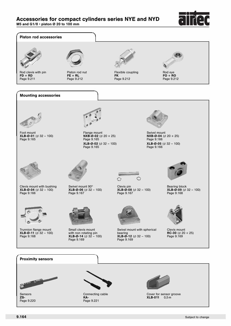
Mounting accessories
Foot mountXLB-Ø-01 (l 32 – 100)Page 9.165
Flange mountNXB-Ø-02 (l 20 + 25)Page 9.165
XLB-Ø-02 (l 32 – 100)Page 9.165
Clevis mount with bushingXLB-Ø-04 (l 32 – 100)Page 9.166
Swivel mountNXB-Ø-04 (l 20 + 25)Page 9.166
XLB-Ø-05 (l 32 – 100)Page 9.166
Clevis pinXLB-Ø-08 (l 32 – 100)Page 9.167
Swivel mount 90hXLB-Ø-06 (l 32 – 100)Page 9.167
Swivel mount with sphericalbearingXLB-Ø-12 (l 32 – 100)Page 9.169
Trunnion flange mountXLB-Ø-11 (l 32 – 100)Page 9.168
Small clevis mount with non rotating pinXLB-Ø-14 (l 32 – 100)Page 9.169
Clevis mountRC-30 (l 20 + 25)Page 9.169
Bearing blockXLB-Ø-09 (l 32 – 100)Page 9.168
Accessories for compact cylinders series NYE and NYDM5 and G1/8 • piston Ø 20 to 100 mm
Piston rod accessories
Proximity sensors
Flexible couplingFKPage 9.212
SensorsZS-Page 9.220
Connecting cableKA-Page 9.221
Cover for sensor grooveXLB-011 0,5 m
Rod eyeFO + ROPage 9.212
Rod clevis with pinFD + RDPage 9.211
Piston rod nutFE + RLPage 9.212

9
9.165Subject to change
Order number Ø D E Ø FB L4 MF R S TF TG UF
NXB-020-02 12 36 6.6 4.6 10 – M5 x 20 * 55 22 70
NXB-025-02 12 40 6.6 4.6 10 – M5 x 20 * 60 26 76
XLB-032-02 30 45 7 5 10 32 M6 x 20 64 32.5 80
XLB-040-02 35 52 9 5 10 36 M6 x 20 72 38 90
XLB-050-02 40 65 9 6.5 12 45 M8 x 20 90 46.5 110
XLB-063-02 45 75 9 6.5 12 50 M8 x 20 100 56.5 120
XLB-080-02 45 95 12 9 16 63 M10 x 25 126 72 150
XLB-100-02 55 115 14 9 16 75 M10 x 25 150 89 170
H11 H13 – 0.5 JS14 JS14 *JS13 ± 0.2JS14
Order number Ø AB AH AO AU AT E L7 R2 S TG TG2 TR
XLB-032-01 7 32 11 24 4 45 30 15 M6 x 20 32.5 16.25 32
XLB-040-01 10 36 8 28 4 52 30 17.5 M6 x 20 38 19 36
XLB-050-01 10 45 15 32 5 65 36 20 M8 x 20 46.5 23.25 45
XLB-063-01 10 50 13 32 5 75 35 22.5 M8 x 20 56.5 28.25 50
XLB-080-01 12 63 14 41 6 95 47 22.5 M10 x 20 72 36 63
XLB-100-01 14.5 71 16 41 6 115 53 27.5 M10 x 20 89 44.5 75
H14 JS16 ± 0.2 H15 ± 0.2 JS14
Flange mount
Ø 32 – 100 = XLB-…
Foot mount (1 pair)
Material: steel (zinc-plated)
EN ISO 4762
DIN 7984
Material: steel (zinc-plated)
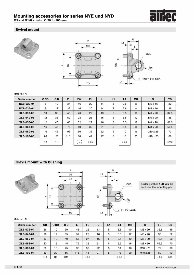
Mounting accessories for series NYE und NYDM5 and G1/8 • piston Ø 20 to 100 mm
Ø 20 – 25 = NXB-…
9.166 Subject to change
Order number Ø CD Ø D E EW FL L L1 L4 MR S TG
NXB-020-04 8 12 34 16 20 14 3 2.6 8 M5 x 16 22
NXB-025-04 8 12 38 16 20 14 3 2.6 8 M5 x 16 26
XLB-032-05 10 30 45 26 22 13 5 5.5 10 M6 x 20 32.5
XLB-040-05 12 35 52 28 25 16 5 5.5 12 M6 x 20 38
XLB-050-05 12 40 65 32 27 16 5 6.5 12 M8 x 20 46.5
XLB-063-05 16 45 75 40 32 21 5 6.5 16 M8 x 20 56.5
XLB-080-05 16 45 95 50 36 22 5 10 16 M10 x 25 72
XLB-100-05 20 55 115 60 41 27 5 10 20 M10 x 25 89
H9 H11 – 0.2 ± 0.2 ± 0.5 ± 0.2– 0.6
Swivel mount
Material: Al
Order number CB Ø CD Ø D E FL L L1 L4 MR S TG UB
XLB-032-04 26 10 30 45 22 13 5 5.5 10 M6 x 20 32.5 45
XLB-040-04 28 12 35 52 25 16 5 5.5 12 M6 x 20 38 52
XLB-050-04 32 12 40 65 27 16 5 6.5 12 M8 x 20 46.5 60
XLB-063-04 40 16 45 75 32 21 5 6.5 16 M8 x 20 56.5 70
XLB-080-04 50 16 45 95 36 22 5 10 16 M10 x 25 72 90
XLB-100-04 60 20 55 115 41 27 5 10 20 M10 x 25 89 110
H14 H9 H11 ± 0.2 ± 0.5 ± 0.2 h13
Clevis mount with bushing
Material: Al
EN ISO 4762
Mounting accessories for series NYE und NYDM5 and G1/8 • piston Ø 20 to 100 mm
Order number XLB-xxx-48includes the mounting pin.

9
9.167Subject to change
Order number BR BT Ø CK Ø D EA EM GL Ø HB L2 LD PH RA TE UL UR
XLB-032-06 10 8 10 21 10 26 21 6.6 1.6 3 32 18 38 51 31
XLB-040-06 11 10 12 21 15 28 24 6.6 1.6 3 36 22 41 54 35
XLB-050-06 13 12 12 21 16 32 33 9 1.6 3 45 30 50 65 45
XLB-063-06 15 14 16 21 16 40 37 9 1.6 3 50 35 52 67 50
XLB-080-06 15 14 16 21 20 50 47 11 2.5 3 63 40 66 86 60
XLB-100-06 19 17 20 11 20 60 55 11 2.5 3 71 50 76 96 70
H9 JS14 H13 JS15 JS14 JS14
Swivel mount 90°
Material: Al
Order number A Ø B Ø EK EL LB
XLB-032-08 53 9.6 10 46 1.1
XLB-040-08 60 11.5 12 53 1.1
XLB-050-08 68 11.5 12 61 1.1
XLB-063-08 78 15.2 16 71 1.1
XLB-080-08 98 15.2 16 91 1.1
XLB-100-08 118 19 20 111 1.3
e 8 + 2
Clevis pin
Material: steel (zinc-plated)
Snap rings are included.
Mounting accessories for series NYE und NYDM5 and G1/8 • piston Ø 20 to 100 mm

9.168 Subject to change
Order number Ø A Ø B C Ø CR FK FN Ø HB LA NH TH UL
XLB-032-09 11 22 10.5 12 15 30 6.6 7 18 32 46
XLB-040-09 15 28 12 16 18 36 9 9 21 36 55
XLB-063-09 18 32 13 20 20 40 11 11 23 42 65
XLB-100-09 20 39 16 25 25 50 14 13 28.5 50 75
H9 ± 0.1 H13 ± 0.2
Material: steel (zinc-plated), bronze
Bearing block
Order number = 1 pair
Order number D L L4 S TD TG TK TL Ø TM US
XLB-032-11 30 6.5 8 M6 x 20 12 32.5 14 12 50 46
XLB-040-11 35 9 13 M6 x 25 16 38 19 16 63 59
XLB-050-11 40 9 11 M8 x 25 16 46.5 19 16 75 69
XLB-063-11 45 11.5 16 M8 x 30 20 56.5 24 20 90 84
XLB-080-11 45 11.5 14 M10 x 30 20 72 24 20 110 102
XLB-100-11 55 14 19 M10 x 35 25 89 29 25 132 125
H11 + 0.2 e9 ± 0.2 h14 h14
Trunnion flange mount
Material: steel (zinc-plated)
Mounting accessories for series NYE und NYDM5 and G1/8 • piston Ø 20 to 100 mm

9
9.169Subject to change
Order number Ø CX Ø D DL E EP EX L L1 L3 L4 MS R1 S TG
XLB-032-12 10 30 22 45 10.5 14 12 7 – 5.5 16 – M6 x 20 32.5
XLB-040-12 12 35 25 52 12 16 15 7 – 5.5 18 – M6 x 20 38
XLB-050-12 16 40 27 65 15 21 15 7 51 6.5 21 19 M8 x 20 46.5
XLB-063-12 16 45 32 75 15 21 20 7 – 6.5 23 – M8 x 20 56.5
XLB-080-12 20 45 36 95 18 25 20 9 74 10 28 24 M10 x 25 72
XLB-100-12 20 55 41 115 18 25 25 9 – 10 30 – M10 x 25 89
H7 H11 ± 0.2 ± 0.1 ± 0.5 ± 0.2
Order number CF CG CP D E FM L1 L4 L10 R4 S SR TG
XLB-032-14 10 14 34 30 45 22 5 5.5 9 17 M6 x 20 10 32.5
XLB-040-14 12 16 40 35 52 25 5 5.5 9 20 M6 x 20 12 38
XLB-050-14 16 21 45 40 65 27 5 6.5 11 22 M8 x 20 14 46.5
XLB-063-14 16 21 51 45 75 32 5 6.5 11 25 M8 x 20 18 56.5
XLB-080-14 20 25 65 45 95 36 5 10 14 30 M10 x 25 20 72
XLB-100-14 20 25 75 55 115 41 5 10 14 32 M10 x 25 22 89
F7 D10 d 12 H11 ± 0.2 ± 0.5 ± 0.2
Material: Al, Clevis pin steel (zinc-plated)
Small clevis mount with non rotating pin
Swivel mount with spherical bearing
Material: Al
Mounting accessories for series NYE und NYDM5 and G1/8 • piston Ø 20 to 100 mm
Clevis mount for Ø 20 + 25
Order number B B1 C H L N O R S E
RC-30 6.6 8 20 30 32 16.1 30 10 4 6
Material: steel (zinc-plated)
9
9.211Subject to change
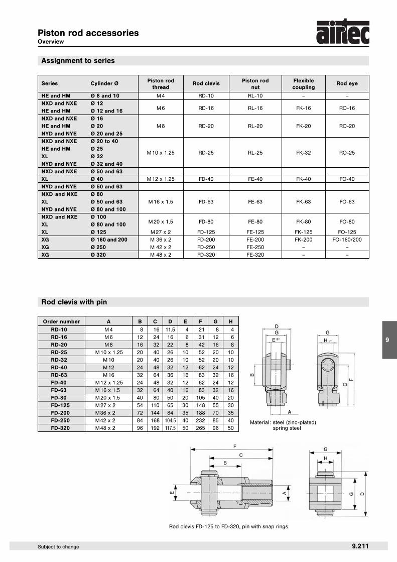
Piston rod accessoriesOverview
Order number A B C D E F G H
RD-10 M 4 8 16 11.5 4 21 8 4
RD-16 M 6 12 24 16 6 31 12 6
RD-20 M 8 16 32 22 8 42 16 8
RD-25 M 10 x 1.25 20 40 26 10 52 20 10
RD-32 M 10 20 40 26 10 52 20 10
RD-40 M 12 24 48 32 12 62 24 12
RD-63 M 16 32 64 36 16 83 32 16
FD-40 M 12 x 1.25 24 48 32 12 62 24 12
FD-63 M 16 x 1.5 32 64 40 16 83 32 16
FD-80 M 20 x 1.5 40 80 50 20 105 40 20
FD-125 M 27 x 2 54 110 65 30 148 55 30
FD-200 M 36 x 2 72 144 84 35 188 70 35
FD-250 M 42 x 2 84 168 104.5 40 232 85 40
FD-320 M 48 x 2 96 192 117.5 50 265 96 50
Assignment to series
Rod clevis with pin
Material: steel (zinc-plated)spring steel
Rod clevis FD-125 to FD-320, pin with snap rings.
Series Cylinder Ø Piston rod Rod clevis Piston rod Flexible Rod eyethread nut coupling
HE and HM Ø 8 and 10 M 4 RD-10 RL-10 – –
NXD and NXE Ø 12HE and HM Ø 12 and 16 M 6 RD-16 RL-16 FK-16 RO-16
NXD and NXE Ø 16HE and HM Ø 20 M 8 RD-20 RL-20 FK-20 RO-20
NYD and NYE Ø 20 and 25NXD and NXE Ø 20 to 40HE and HM Ø 25
M 10 x 1.25 RD-25 RL-25 FK-32 RO-25XL Ø 32NYD and NYE Ø 32 and 40NXD and NXE Ø 50 and 63XL Ø 40 M 12 x 1.25 FD-40 FE-40 FK-40 FO-40
NYD and NYE Ø 50 and 63NXD and NXE Ø 80XL Ø 50 and 63 M 16 x 1.5 FD-63 FE-63 FK-63 FO-63
NYD and NYE Ø 80 and 100NXD and NXE Ø 100XL Ø 80 and 100 M 20 x 1.5 FD-80 FE-80 FK-80 FO-80
XL Ø 125 M 27 x 2 FD-125 FE-125 FK-125 FO-125
XG Ø 160 and 200 M 36 x 2 FD-200 FE-200 FK-200 FO-160/200
XG Ø 250 M 42 x 2 FD-250 FE-250 – –
XG Ø 320 M 48 x 2 FD-320 FE-320 – –

9.212 Subject to change
Piston rod accessories
Order number d3 d d1 d2 d4 d5 B C1 W L3 L4 h1 “RO-16 M 6 6 8.9 20 10 13 9 6.75 11 12 40 30 13
RO-20 M 8 8 10.4 24 12.5 16 12 9 14 16 48 36 14
RO-25 M 10 x 1.25 10 12.9 28 15 19 14 10.5 17 20 57 43 13
RO-32 M 10 10 12.9 28 15 19 14 10.5 17 20 57 43 13
RO-40 M 12 12 15.4 32 17.5 22 16 12 19 22 66 50 13
RO-50 M 16 16 19.3 42 22 27 21 15 22 28 85 64 15
FO-40 M 12 x 1.25 12 15.4 32 17.5 22 16 12 19 22 66 50 13
FO-63 M 16 x 1.5 16 19.3 42 22 27 21 15 22 28 85 64 15
FO-80 M 20 x 1.5 20 24.3 50 27.5 34 25 18 30 33 102 77 14
FO-125 M 27 x 2 30 34.8 70 40 50 37 25 41 51 145 110 17
FO-160/200 M36 x 2 35 37.7 80 46 58 43 28 50 56 165 125 16
FO-250 M42 x 2 40 45.1 91 53 65 49 33 55 60 187 142 16
FO-320 M48 x 2 50 56.6 117 65 75 60 45 65 65 218 162 14
Order number A B C D E Ø F Ø G Ø H I L M SW SW1 SW2 ß°FK-16 M 6 35 11 2.5 17.5 6 8.5 14.5 13 1 12.5 5 7 10 6°
FK-20 M 8 57 21 5 26 8 12.5 19 17 2 16 7 11 13 8°
FK-32 M 10 x 1.25 71.5 20 7.5 35 14 22 32 30 2 22 12 19 17 8°
FK-33 M 10 71.5 20 7.5 35 14 22 32 30 2 22 12 19 17 8°
FK-40 M 12 x 1.25 75.5 24 7.5 35 14 22 32 30 2 22 12 19 19 8°
FK-41 M 12 75.5 24 7.5 35 14 22 32 30 2 22 12 20 19 9°
FK-63 M 16 x 1.5 104 32 10 53 22 32 45 41 2 30 20 27 24 6°
FK-80 M 20 x 1.5 119 40 10 53 22 32 45 41 2 37 20 27 30 6°
FK-125 M 27 x 2 147 54 10 60 32 57 70 65 2 48 24 54 41 8°
FK-200 M 36 x 2 190 72 15.5 77 39 57 75 70 2 68 32 54 55 8°
Order number A B C
RL-10 M 4 3.2 7
RL-16 M 6 4 10
RL-20 M 8 5 13
RL-25 M 10 x 1.25 5 17
RL-32 M 10 5 17
RL-40 M 12 6 19
RL-50/63 M 16 8 24
FE-40 M 12 x 1.25 6 19
FE-63 M 16 x 1.5 8 24
FE-80 M 20 x 1.5 10 30
FE-125 M 27 x 2 13.5 41
FE-200 M 36 x 2 18 55
FE-250 M 42 x 2 21 65
FE-320 M 48 x 2 24 75
Material: steel (zinc-plated)
Piston rod nut
Rod eye
Material: steel (zinc-plated)stainless steel
Material: steel (zinc-plated)
Flexible coupling
view A

9.220 Subject to change
Proximity sensors
ZS-5600, ZS-6700, ZS-7300; A = 3.000 ± 20
ZS-5700; A = 5.000 ± 20
ZS-5700-10; A = 10.000 ± 20
Order number ZS-5600 ZS-5601 ZS-5700 ZS-5700-10 ZS-5701
Design 2-pole Reed sensor 3-pole Reed sensor*(non-polarized) normally open normally open
Cable l 2.8, PUR
Cable cross section n/a
Cable length 3 m 0.3 m 5 m 10 m 0.3 m
Cable plug – M 8 – – M 8
Overtravel speed n/a
Max. absolute hysteresis n/a
Temperature drift n/a
min. absolute repeat accuracy n/a
Operating temperature – 10 °C … + 70 °C
Degree of protection IP 67
Housing material Plastic
Switching status indication LED red LED yellow
Rated operational voltage 5 … 240 V AC/DC 5 … 60 V AC/DC 5 … 30 V DC
Rated operational DC 3 … 100 mA ≤ 500 mAcurrent IE AC 3 … 100 mA ≤ 500 mA
Breaking capacity ≤ 10 W
No-load current n/a ≤ 10 mA
Max. OFF-state current 0 mA
Max. switching frequency ≤ 0.2 kHz
Rated insulation voltage n/a
Short-circuit protection no
Max. voltage drop at IE ≤ 2.5 V ≤ 0.1 V
Wire breakage no
Reverse polarity protection yes
Vibration resistance 9 g (1.5 mm, 10 – 55 Hz – 10 Hz)
Shock resistance 30 g (11 ms)
Explosion proof –
ZS-5600 ZS-5601
Function principlesMagnetic field sensors are actuated by magnetic fields and are especially suited for piston position detection in pneumatic cylinders.Based on the fact that magnetic fields can permeate non-magnetizable metals, it is possible to detect a permanent magnet attached to thepiston through the aluminum wall of the cylinder.
Mounting tipThe sensor is firmly fixed in the groove by clockwise rotation of the screw.
ZS-5700, ZS-5700-10 ZS-5701
ZS-5601, ZS-5701, ZS-6701
ZS-6700, ZS-7300 ZS-6701, ZS-7302 (dimensions for ZS-7302, page 9.221)
DimensionsWiring diagram
1
4
3
* Useable as 2-wire contact, voltage 0 … 30 V AC / 0 … 30 V DC, LED has no function.
Proximity sensors Reed contact

9
9.221Subject to change
Order number ZS-6700 ZS-6701 ZS-7300 ZS-7302
Design electronic, magnet-induktive sensor,normally open PNP output
Cable l 2,8, PUR n/a
Cable cross section n/a 3 x 0,14 mm2
Cable lengths 3 m 0,3 m 6 m 0,3 m
Cable plug – M 8 – M12
Overtravel speed n/a ≤ 10 m/s
Max. absolute hysteresis n/a n/a
Temperatur drift n/a ≤ 0,1 mm
Min. absolute repeat accuracy n/a ≤ 0,2 mm
Operating temperature – 10 °C … + 70 °C – 25 °C … + 60 °C
Degree of protection IP 67 IP65/IP67 IP 67
Housing material Plastic Body: PA; Mounting band: stainless steel
Switching status indication LED green LED yellow
Rated operational voltage 5 … 30 V DC 10 … 30 V DC
Rated operational DC ≤ 200 mA ≤ 100 mAcurrent IE AC – –
Breaking capacity 6 W n/a
No-load current ≤ 10 mA ≤ 10 mA
Max. OFF-state current n/a n/a
Max. switching frequency ≤ 1 kHz > 6.000 Hz > 10.000 Hz
Rated insulation voltage n/a n/a
Short-circuit protection yes yes
Max. voltage drop at IE ≤ 1,0 V ≤ 2,5 V
Wire breakage yes n/a
Reverse polarity protection yes yes
Vibration resistance 9 g (1.5 mm, 10 – 55 Hz – 10 Hz) n/a
Shock resistance 50 g (11 ms) n/a
Explosion proof – EX II 3G Ex nA T4 X EX II 3D Ex tc IIIC T125°C Dc XEX II 3D Ex tD A22 IP67 T125°C X
Order number Piston Ø
NT-250 8 to 25 mm
NT-500 32 to 63 mm
Mounting bracket for round cylinder Ø 8 – 63 mm
Connecting cable for ZS-5601, ZS-5701 and ZS-6701
BU 3
4 BK
1 BN
Proximity sensors electronic
Cable: PUR, black, 3 x 0.25 mm2, l 3.9, high flexibleOperating voltage 0 … 48 V AC/ DC
Material: metal, plastic PA GI/6T
Proximity sensors
Order number Length of cable Connection
KA-30 3 m 8 mm sensor snap-in, straight
KA-50 5 m 8 mm sensor snap-in, straight
KA-51 5 m 8 mm sensor snap-in, 90°
KA-100 10 m 8 mm sensor snap-in, straight
KA-101 10 m 8 mm sensor snap-in, 90°
Dimensions for ZS-7302