Embed Size (px)
Citation preview

(Giro)form Perfect in FormModel Management in the Lab: An efficientModel System by AmannGirrbach – Part 1
A contribution by dental master technician ZTM Stefan Schunke, Fürth/Germany
community & competence
The International Journal of Dental Technology
Reprint
Amann Girrbach AGHerrschaftswiesen 16842 Koblach • AustriaPhone +43 (5523) 62333-394Fax +43 (5523) 55990www.amanngirrbach.com
Kindly offered by:

dd T E C H N I Q U E
2 dental dialogue UK VOLUME 4 2010 ©
(Giro)form Perfect in Form
Don’t worry. Stefan Schunke is not going to bore you with grey theories on proper laboratory management inthis series of articles. The experienced practitioner’s objective is to demonstrate the correct management ofprocesses in the laboratory by means of a proper system. In this context, he would like to refer to the ety-mological origin of the term “management”, whose potential source may be taken from the Latin “manusagree”, i.e. leading by the hand. This is the moment to lean back and be guided through the topics Model(Part 1), Framework (Part 2) and Articulator Management (Part 3).
A contribution by dental master technician ZTM Stefan Schunke, Fürth/Germany
Model Management in the Lab: An efficient Model System by AmannGirrbach – Part 1
Indeces
• Impression• Dowel Pin• Function• Model manage-
ment• Model systems• Split Cast• Information on the
gingivae
Introduction
In our everyday routine, we are con-fronted with working instructions and,of course, models. And does the will-ing reader of this article not know thephenomenon of a customer sayingsomething such as “look at the modelsand you know how the lab is working”or colleagues confronting you with thestatement that “the models are thebusiness cards of the laboratory”? Thismay sound like nonsense to some peo-ple. Is it really? Just take a look at thefigures 1 - 3. I will comment on thesefigures individually. Figure 1 shows the classical “saw-cutmodel”. A dowel pin in the originalsense was used to remove the modeldie. This is a pin that at the end of its re-tentive part takes the shape of a thinmandrel and may be directly put in theimpression material. If several of thesepins have to be used for one die, theremay be the danger, due to divergences,that the die may no longer be removedor wider saw cuts are necessary. Ofcourse such a pin does not guide prop-erly and the die wobbles. Then the im-pression is only partially cast using the“oh so expensive” class IV plaster in or-
der to save “costs”. Finally, the remainderof the impression is cast with a class 2plaster and then based, however, with-out removing the class IV segment andwithout using a separating agent. Thosewho look properly will recognize thepin in the centre of the preparation mar-gin. Is such a model reliable? I receivedthis model at the beginning of the 90s. Figure 2 shows a further disaster model.This is a model upon which the finishedunit was handed in. The colleagueproudly told to me that “money playedno part with this patient and everythingwas paid”. What do you think? Is this a“reliable” model? The photo of thismodel was taken at the end of the 90s. A model of the year 2009 is displayed infigure 3. This model was to provide thebasis for a removable unit… If this wereyour personal model situation, wouldyou trust the restoration constructedupon it? In as far as these parameters de-scribed at the beginning are concernedthe comments made on behalf of thedentists and colleagues are more thanappropriate. Models have to be consid-ered and treated like the documents of apublic notary. Only on the basis of in-tact documents, here models, may wedocument or prove processes, plans,
preparations and so forth. This is equal-ly true in the legal sense. The author of this article is of the opin-ion that prosthetic dentistry requiresprecision saw-cut models. The produc-tion requires some effort and this is alsodocumented in the costs for the patient.However, what happens if the work hasto be repeated because of the model?This is why the author thinks ModelManagement should be taken on by re-sponsible hands. In addition, the mod-els have to be treated with great atten-tion and professional care so that afterthe work has been completed it is still inone piece, and if possible, undamaged.
Different models and model systems
In diverse publications, the author haspointed out why he is in favour of a sys-tem with modern dowel pins. Until2008, for various reasons, the authorhad been against a system with acrylicbases instead of plaster bases. However,this has changed.In the event a good precision saw-cutmodel with a plaster base (fig. 4) isused, the pins are guided into acrylicsleeves embedded in plaster. As a rule,
Categories
System relatedSeries of articles
Contact address
AmannGirrbach AGFon +43 5523 623 33-0 [email protected]

T E C H N I Q U E dd
© VOLUME 4 2010 dental dialogue UK 3
Figs. 1 to 3 Do these models give the impression of reliable quality and expertise, or even accurately fitting dental restorations?The author’s opinion: Not in that state!
Fig. 4 Clean and well made precisionsaw-cut model with additionally inte-grated block pins.
Figs. 5 and 6 Clean and well made precision saw-cut model from Giroform Systems.
there is an additional so-called blockpin located between the dies in order toprevent the smallest movement be-tween the dies. However, this is ex-tremely difficult to implement when re-constructing lower anteriors with indi-vidually made veneers.
The methodology of the Giroform model facilitates the procedure in sucha case (figs. 5 and 6). The author ini-tially was very sceptical about thistechnology. Costs were one reason. Ifone compares the high-quality systemswith one another in this aspect, thisfeeling of resentment cannot be con-firmed. However, the exact calculationand the proper construction of a Giro-form model will not be discussed fur-ther in this three-part article. Never-theless, it is a fact for the author thatthe production (time and costs) aswell as the proper workflow in the lab-oratory have become much more effi-cient with the system. Former systemsdid not allow for any reasonable splitcast specimen, for ex ample, this is a de-cisive feature of the restoration fo-cused on function. A further problem the system present-ed was that the delivered dental arches
could not be based accordingly. Asmay be seen from the photos, this issuecan be mastered (figs. 7 to 10). It should be mentioned in this contextthat the author has always required un-cut models (master models) in addition.The problem with the Giroform systemis that in order to produce an upper jawsaw-cut model the palatinal area had tobe removed from the impression. Howto proceed if there is only one impres-sion? Even here, AmannGirrbach’smodel system offers the proper solu-tion. As a rule there are always two iden-tical impressions.
The Giroform system user then has access to two models – one uncut and asaw-cut model (figs. 11 and 12). Thereason why both models are so impor-tant becomes clear, once a saw-cutmodel is compared to the situation inthe mouth (fig. 13). This picture clearlyshows how many biological pieces ofinformation are lost through sawingand opening the preparation margin onthe cast model. Information about thebiological width, the emergence profile,approximal contacts, light ridges andmuch more, may not be interpreted andtaken over correctly by means of the
saw-cut model. Therefore, two modelsare unavoidable – a saw-cut model andan uncut one. The additional work thatoccurs through this complex modelproduction, and the working on bothmodels, has to be mirrored in a clearlyimproved result on the one hand but also in the price of the restoration onthe other hand. The author sees a further advantage ofthe Giroform system in the simplifiedproduction of individually constructedveneers. The difficulties encounteredwith the production of veneers on asaw-cut model with dental plaster baseare of different origin. On the one hand,in particular with the lower anteriorteeth the refractory dies cannot bemade with sufficient stability. A furtherproblem is that the dies have to be keptdamp, however, a plaster model shouldnot come into contact with too muchwater for precision reasons. The authoruses a transparent film on the model asan intermediate solution with Pindexmodels (fig. 14).
The solution the Giroform model sys-tem provides for this problem, looks rel-atively easy. However, despite all this,one has to take into account a few de-

dd T E C H N I Q U E
4 dental dialogue UK VOLUME 4 2010 ©
tails that seem to be all the more impor-tant. The model system incorporates aduplicating form that may be used withthe previously made base plate. In addi-tion, the system also has refractory pins,so that the dies may be re-aligned per-fectly and reproducibly, which is benefi-cial to the reconstructed function.When constructing the refractory dies,it is essential to ensure there are two ref-erence pins in the duplicating material,in this case silicone. The base plate hasto be exactly positioned on the duplicat-ed form. If this is not observed, the orig-inal position of the plaster die may notcorrespond with the actual position(figs. 15 and 16).
It is surprising that the saw-cut and thebased Giroform models are duplicatedin such a good way (fig. 17). The authorwould not have expected the thin sawslits to fill with duplicating material (fig.18). For this purpose, a 1:1 siliconefrom the company Dreve with a shorehardness of 32 was used. The initialworry that the silicone was possibly toohard was unfounded. For exactly thethin silicone lamellae (also the positiveof the saw-cuts) require a silicone mate-rial with a high degree of hardness.
A further problem had to be solved. Forit is almost impossible to cast out all re-fractory dies at once and without any
mistakes. Furthermore, there is the dan-ger that the thin lamellae will bendwhen casting the refractory die materialat various stages. Even if the dies fitmore or less correctly on the base plate,it is not possible to alternate with plasterdies. As the author duplicates all his dies,there are always second and third diesavailable. Exactly these plaster duplicatedies are positioned as dummies in theduplicated form on an alternating basis.This means the thin lamella is supportedby the plaster dummies, and the hollowmoulds are stabilized (fig. 19).The result is simply convincing. We arenow in a position to combine our work-ing model according to our gusto, and
Figs. 7 to 10 How can the cast dental arches be transferred onto the Giroform System? Easy, the dental arch is cut to accommodate, and can thenbe based and finished as usual.
Figs. 11 to 13 Uncut models are a must if you wish to include the biological factors in the restoration.
Fig. 14 A transparent film protects the saw-cutmodels with the plaster bases from excess waterand prevents the refractory dies from drying out.
Figs. 15 and 16 If you wish to achieve exact results with the Giroform System, it is necessary to ob-serve and follow the manufacturer’s instructions, as with any other system. Otherwise inaccuracies willoccur, such as in this case, not necessarily with the fit, but with the approximal contacts.
T E C H N I K dd
© VOLUME 4 2010 dental dialogue UK 5
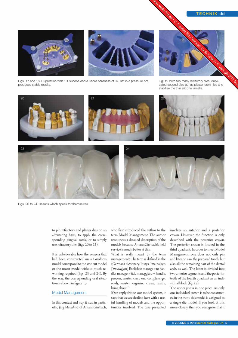
to pin refractory and plaster dies on analternating basis, to apply the corre-sponding gingival mask, or to simplyuse refractory dies (figs. 20 to 22).
It is unbelievable how the veneers thathad been constructed on a Giroformmodel correspond to the saw-cut modelor the uncut model without much re-working required (figs. 23 and 24). Bythe way, the corresponding oral situa-tion is shown in figure 13.
Model Management
In this context and way, it was, in partic-ular, Jörg Mannherz of AmannGirrbach,
who first introduced the author to theterm Model Management. The authorrenounces a detailed description of themodels because AmannGirrbach’s fieldservice is much better at this.What is really meant by the term management? The term is defined in the(German) dictionary. It says: “ma|na|gen['mɛnɪʤən] English to manage = to han-dle; manage < ital. maneggiare = handle,process, master, carry out, complete, getready, master, organize, create, realize,bring about;“If we apply this to our model system, itsays that we are dealing here with a use-ful handling of models and the oppor-tunities involved. The case presented
involves an anterior and a posteriorcrown. However, the function is onlydescribed with the posterior crown.The posterior crown is located in thethird quadrant. In order to meet ModelManagement, one does not only pinand later on saw the prepared tooth, butalso all the remaining part of the dentalarch, as well. The latter is divided intotwo anterior segments and the posteriorteeth of the fourth quadrant as an indi-vidual block (fig. 25).The upper jaw is in one piece. As onlyone individual crown is to be construct-ed in the front, this model is designed asa single die model. If you look at thismore closely, then you recognize that it
Figs. 17 and 18 Duplication with 1:1 silicone and a Shore hardness of 32, set in a pressure pot,produces stable results.
Fig. 19 With too many refractory dies, dupli-cated second dies act as plaster dummies andstabilise the thin silicone lamella.
Figs. 20 to 24 Results which speak for themselves
20 21 22
23 24

dd T E C H N I Q U E
6 dental dialogue UK VOLUME 4 2010 ©
is not perfect in the gingiva area (fig. 26)as is the case in real life. After the mount-ing of the models, the models first of allhave to be ground in order to adjust thevertical distance correctly. Here it is bestto use small strips originating from arescue foil. Normally the supportingpin is put into the zero position to beginwith (figs. 27 and 28).If this foil is used to control the jaw situa-tion of the overall dental arch, one mostlyfinds that the rescue foil is not held by allteeth in the same manner. The reasons forthis are diverse and sufficiently known. It
is correct that the dentist had to establisha so-called grinding in protocol. The pro-tocol shows the teeth that hold the foil inthe mouth and where this is not the case.This information is then marked on theteeth status order with a plus or a minus.If you do not get this information, this isthe moment where Model Manage-ment becomes valid. Step by step, thesegments are taken out of the acrylicplate and the lowest position of the re-maining teeth is determined by meansof the rescue foil and via the supportingpin. As a rule the supporting pin is read-
justed in the region of 0,5 - 1 millimetre.Depending on the state of the remain-ing teeth this area may also be account-ed for three millimetres. In this case, thelowest pin position was determinedwith the lower anterior tooth segment(figs. 29 to 31).The question arises, how much the over-all teeth really should be ground in. In thiscontext, it is necessary to examine the en-tire dentition carefully. In most cases thefacets provide more precise informationthat allows us to recognize the degree ofsensible grinding required.
Fig. 25 It is essential to di-vide the saw-cutmodels into anteriorand posterior seg-ments so that bettercontrol of the differ-ent functions and thevertical dimension ispossible later.
Figs. 26 to 28 System imminent dis-crepancies usuallylead to uneven occlu-sion in the plastermodels. The teeth willtherefore not be ableto hold the rescue foilevenly. The articulatorpin is on zero.
25
26 27 28

T E C H N I Q U E dd
© VOLUME 4 2010 dental dialogue UK 7
On the basis of the defined supportingpin height the porcelain onlay is pro-duced on the refractory die in the cen-tric position (fig. 32). If the eccentricposition is also checked, then one maysee wonderfully even tooth guidance.The canine guides and thus protects theoverall posterior teeth area (fig. 33).
However, wouldn’t it be interesting to findout what happens in the occlusal close-upregion? What does the author mean bythis? In the following digression you willfind more food for thought.
Figure 33 shows an articulated case situa-tion. How do we know that this is thesame situation as in the patient’s mouth?It could be that this is the actual position,but maybe it isn’t. If the upper canines aresituated directly over the lower canines,then the teeth are already classed as misaligned. Fact is that the articulatordoes not and cannot reproduce everymandibular movement. This topic will bedealt with in depth in part 2. Anothermystery: What happens if the patient hasa parafunctional bite and then appliespressure in the masticatory system? It is
a well known fact for example, that thelower orthodontic appliance moves andtwists with chewing movements. In addi-tion to this it is not unimportant to take acloser look at the occlusal region to un-derstand exactly what happens directly atthe beginning and at the end of eachmovement. For this reason all the modelsegments are removed from the model,apart from the die with the porcelain on-lay – in this case the last tooth in the thirdquadrant. Starting from the centric articu-lator position, the eccentric movementsare then reproduced (figs. 34 and 35).
Figs. 29 to 32 With the aid of the in-
dividual model seg-ments, the dental
technician is able tofind the best possible
vertical dimension,despite the lack of in-
formation. This re-sults in a distinct im-provement in occlu-
sion and less grindingfor the dentist.
Fig. 33 The teeth move outof occlusion wonder-fully evenly due to theanterior canine guid-ance.
Figs. 34 and 35When checking the
eccentric movement itbecomes apparent
which tooth is guiding.
29 30 31
32 33
34 35

dd T E C H N I Q U E
8 dental dialogue UK VOLUME 4 2010 ©
This distinctly shows that both themolars guide the movements (groupguidance).If you take a look at the buccal structureof the first upper molar, you will see thatthe mesio-buccal cusp is too long. Thedental technician cannot change this fact.It might be possible to inform the dentistof this, so that he may shorten the cuspfor the lateral protrusive movement.But is it really necessary in this case?There are two reasons why this wouldn’tbear much relevance. Firstly, the secondmolar is there to protect, and secondly,don’t forget that this is a simulated situa-tion and doesn’t represent the actual situ-ation. All other teeth have been removedfrom the model. Once the third quadrant
model segment with the premolars hasbeen re-inserted, a completely new pic-ture unfolds. First it appears that theguiding tooth is not the 1st premolar butthe 2nd premolar, and through this guid-ance the molars are lead out of occlusion.The 1st molar is further out of occlu-sion than the second (fig. 36). Usuallyin this type of model it is the 1st pre-molar which is the guiding tooth andthe other posterior teeth are led gentlyout of occlusion. Apart from theporcelain onlay, there is nothing wecan change about the rest of the denti-tion. Ideally, natural dentition willshow an even distribution of wear andabrasion. In a case such as this, the au-thor feels it is his duty to protect the
new restoration to be constructed.Otherwise the entire bite would re-quire alteration. If the situation in thepatient’s mouth really is similar to thesituation in the articulator, then theonlay will always be protected by thesurrounding structures (cf. fig. 36).The models have been segmented ac-cordingly so that it is also possible tocheck the lingual situation in the centricand eccentric position. Figure 37 showsclearly how only the buccal cusps re-main in contact during laterotrusion. Inaddition to this, the lingual cusps of the2nd molar glide past much closer thanthe 1st molar (fig. 38). Once again thisshows that the onlay is well protected –even if the bite were to be lowered. In
Figs. 39 to 41 This is Model Man-agement par excel-lence: The othermovements can alsobe checked in uni-son and individually.
Fig. 36 Once the next seg-
ment is inserted, 1stmolar moves out of
occlusion. The occlu-sion plane is correct,
however uneven.
Figs. 37 and 38 This type of modelsegmentation en-ables a clear viewfrom the palatinal di-rection.
36 37
38
39 40
41

T E C H N I Q U E dd
© VOLUME 4 2010 dental dialogue UK 9
general, all other movements are exam-ined using this method. For example,the lateral excursion to the right can beinitially carried out through canineguidance (fig. 39). Once again theteeth part adequately wide out of oc-clusion (fig. 40).As soon as all segments are removed,except for the last molar, the guidancebecomes familiar on the latter. Thismeans that even in a parafunctional sit-uation the new porcelain onlay will beprotected. In this case it is due to thefact that the palatinal cusps of the firstupper molar were made too short (fig.41). This can also be seen in figure 38.Finally, further excursions, such asretrusion, can be examined (fig. 42). In
particular straightforward retrusioncan be observed very well from the oralview. Then the segments are replacedone after the other (fig. 43). From abuccal view it is clear to see that the2nd molar guides this movement aslong as no other segment is in the mod-el (fig. 44). The neighbouring mesial segment,both premolars, is inserted and it thenbecomes apparent that these teeth re-sume guidance during the retrusivemovement from the centric position(fig. 45). At the same time there is noocclusion throughout the entire poste-rior dentition (fig. 46). In other words:If the patient should move his lower jawbackwards, for whatever reason, it will
be guided back into the centric positionover the 1st premolars. If coloured articulation foil is used, thevarious areas can be identified (fig. 47).These areas could only be made visiblebecause there was next to no other seg-ment in the model base. It was only pos-sible for the patient to wear these areasas the anterior and canine guidance hadbeen removed (for one particular rea-son). This could be due to a parafunc-tion, twisting of the lower jaw or general“wear and tear” in the close-up occlusalregion. With the aid of the occlusalcompass these facets can be analysed assuch. The movements merge seamless-ly and cannot be distinctly held apart(fig. 48). In this case it is apparent that
Figs. 42 to 44 The retrusion is ex-
amined
Figs. 45 and 46It is apparent that the1st premolar protectsthe joint and the other
teeth in the retrusiveexcursion.
42 43
44
45 46

dd T E C H N I Q U E
10 dental dialogue UK VOLUME 4 2010 ©
the buccal cusps had the most contactareas (fig. 49). The author believes thisto be an advantage as the stronger buc-cal parts of the crown are used most.Hence these structures protect the joint
and the lingual cusps, acting as a finalbastion (fig. 50). In the next part, Ztm. Stefan Schunke willapproach the topic of adequate frame-work management. Using various case
situations the reader will be introducedto the methodology and its implemen-tation.
To be continued…
About the author
Dental master technician Ztm. Stefan Schunke began his training in 1976 in Leverkusen. In 1981 he successfully completedhis apprenticeship. He then moved on to work with the dental master technician Ztm. Bölte in Düsseldorf. During this time hesuccessfully completed his master’s examination in dental technology as an external student. He recognised the importanceof the biomechanical wax-up concept according to M. H. Polz. In 1988 he started work at the Zahntechnische LaboratoriumM. H. Polz and went on to become a partner in the company. Since 1997, he has been the sole owner of this laboratory. Ste-fan Schunke is the author of several publications since 1987, the main topic being wax-up and milling techniques accordingto functional aspects. In 1991 he received the Pfannenstiel prize for his publications. In 1993, after a year’s break, he becamean instructor for occlusal function and morphology at the Johann Wolfgang Goethe University in Frankfurt. In 2003, he wascertified by the DGÄZ (Deutsche Gesellschaft für Ästhetische Zahnheilkunde eV – The German association for aestheticaldentistry) as “Specialist for Aesthetical Dental Technology”. Furthermore, he also became the Vice President of the DGÄZ.
Contact address:
Ztm. Stefan Schunke • Zahntechnisches Labor Stefan Schunke • Alte Reutstr. 170 • DE-90765 Fürth, GermanyFon +49 911 79037-51 • Fax +49 911 79037-52 • www.schunke-stefan.de
Figs. 47 to 50 Understanding occlusion and function along with correct Model Management produces long-term stability andreliable restorations.
47 48
49 50

T E C H N I K dd
11. JAHRGANG 2010 © dental dialogue 11

d-lab24.com