Embed Size (px)
Citation preview
28TH INTERNATIONAL CONGRESS OF THE AERONAUTICAL SCIENCES
1
Abstract
A standardized data model as common language for disciplinary communication in aircraft design could have a significant impact on the efficiency of conceptual/preliminary design efforts and collaborative research in aircraft design. This paper discusses if such a standard could be established and under which circumstances this would make sense.
The Common Parametric Aircraft Configuration Scheme (CPACS) is introduced as one potential step towards a unified data model. Experiences in coupling established Multidisciplinary Design Optimization (MDO) environments with CPACS are presented and requirements for setting a standard are discussed.
1 Collaborative Design
The search for revolutionary solutions for future scenarios in commercial aviation and the investigations of major technological advances for commercial aircraft require the utilization of physics-based analysis capabilities at the appropriate levels of fidelity. At the same time, the integration of all relevant disciplines is required so that the system-level behavior and performance can be properly understood. For these reasons, the sharing of timely information is required to leverage the necessary tools, skills, and workforce, and to facilitate collaboration across disciplines.
The use of Multidisciplinary Design Optimization (MDO) techniques is currently becoming state-of-the-art also in large projects incorporating multiple, decentralized and
heterogeneous partners. The implementation of a common platform for the communication between the different analysis capabilities with their individual variable spaces is a necessary activity in each of these projects. Often, this step accounts for a significant amount of the project workload and risk. Thus, the creation of a standardized data model to serve as the common language for the communication could have a large beneficial impact on the efficiency of these analysis and design processes.
Information technologies for Product Data Management (PDM) have been commercially available for some time. Many of them build on basic capabilities from Computer Aided Design (CAD) software. The professional handling of design data, including geometries, can be realized also for large projects ranging up to so called Virtual Extended Enterprises. Nevertheless, particularly in collaborative research and creative product development environments, we find that the setup of consortia/teams that attempt to use commercial software suffers from a lack of agility for two particular reasons:
Firstly, PDM and CAD solutions work best within the product family of a particular software vendor. In many cases even the version number of the software is critical to achieve full compatibility. In collaborative design, heterogeneous partners typically form a consortium, usually for a time frame not exceeding three years. A homogeneous software development environment cannot be expected.
Secondly, adapting the interfaces of these heterogeneous tools to a particular data management solution faces two additional hurdles: if proprietary formats of software
COMMUNICATION IN AIRCRAFT DESIGN: CAN WE ESTABLISH A COMMON LANGUAGE?
B. Nagel*, D. Böhnke*, V. Gollnick*, P. Schmollgruber°, A. Rizzi+, G. La Roccax, J. J. Alonso~
* German Aerospace Center, ° French Aerospace Lab, + Royal Institute of Technology Stockholm, x Delft University of Technology, ~ Stanford University [email protected]; [email protected]; [email protected];
[email protected]; [email protected]; [email protected]; [email protected]
B. Nagel et. al.
2
companies are involved, sometimes information is lacking to achieve full connectivity and automation. In contrast, open formats such as the “Standard for the Exchange of Product model data” (STEP), created with the intention to be fully universal, can be extensive resulting in high levels of effort to perform the manual linking of the digital models.
With this in mind, we postulate that the efficiency of collaborative design can be enhanced by an open, central data model that can be used as common language. It is critical that the model be well balanced for the application in order to be as lean as possible and to be versatile enough to permit the representation of a broad design space and the use of high levels of fidelity in the analyses, when needed.
2 Computational Design System
Aiming at advancing interdisciplinary collaboration between its institutes, in 2005 the German Aerospace Center (DLR) began the development of technologies that permit to interlink efficiently an arbitrary number of interdisciplinary analysis capabilities. The central data model, CPACS, is used to establish the coupling of different models and name spaces. It is supported by a suite of software that permits simple handling of CPACS models and the realization of decentralized MDO architectures.
2.1 Data Model CPACS
CPACS is implemented as a Schema Definition (XSD) for the Extensible Markup Language (XML). In this manner, it defines the elements, attributes and structure of all the information that may be used within CPACS models. The explicit data models used for analyses are instantiated following all rules of the XSD and employing only the information that is required for the specific use case. The format is human readable and computer processable.
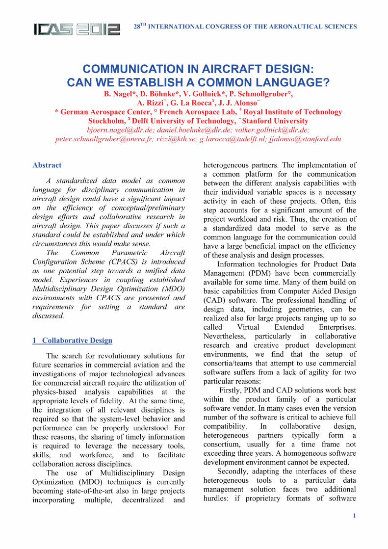
Aiming at applications in aircraft design, the root elements of the data model hierarchy represent the typical components used in the
conceptual design of aircraft. Thus, for low levels of fidelity and small numbers of variables the format is relatively simple, easy to understand, and similar to other parameterizations used in other aircraft conceptual design tools.
Fig. 1. CPACS structure
Complex designs and unconventional configurations can, in principle, be realized by combining different kinds of components. The definition of assemblies uses hierarchies between components permitting a functional description of the entire vehicle. Individual components and assemblies can be used multiple times in higher-order assemblies in an efficient way through the use of Unique Information Identifiers (UIDs). Each time a component is referred to, it can be geometrically transformed through scaling and rotation (relative to the global coordinate system or to the parent assembly) so as to define new components. Due to the hierarchical nature of the data model, transformations of assemblies act on all children elements.
3
Communication in Aircraft Design: Can we establish a Common Language?
When moving from the root of the data hierarchy to its branches, the level of detail increases. Thus, when performing a conceptual design with a CPACS model that only contains the root information, more detailed analyses can be carried out by adding more branches to the original model. In this way, CPACS is capable of handling data for multiple levels of geometric and/or analysis fidelity. The schema definition is set up to support variable-fidelity applications and to avoid conflicts in the data model. However, challenges of variable fidelity such as linking different fidelity-level models are not solved by the data model but must be realized in the design optimization process.
One important feature of CPACS is the handling of both product and process information, i.e. not only the aircraft is described but also tool-specific information to control parts of the analysis process, e.g. control parameters to drive the meshing of geometries for structural analysis.
CPACS is a living format undergoing a structured development process. In principle, CPACS can be expanded to model arbitrary aircraft design problems. The format is published under open source license agreement together with a growing documentation database [1]. A more detailed description of the approach followed in CPACS and the data content is given in [2] and in [3].
2.2 Software Environment
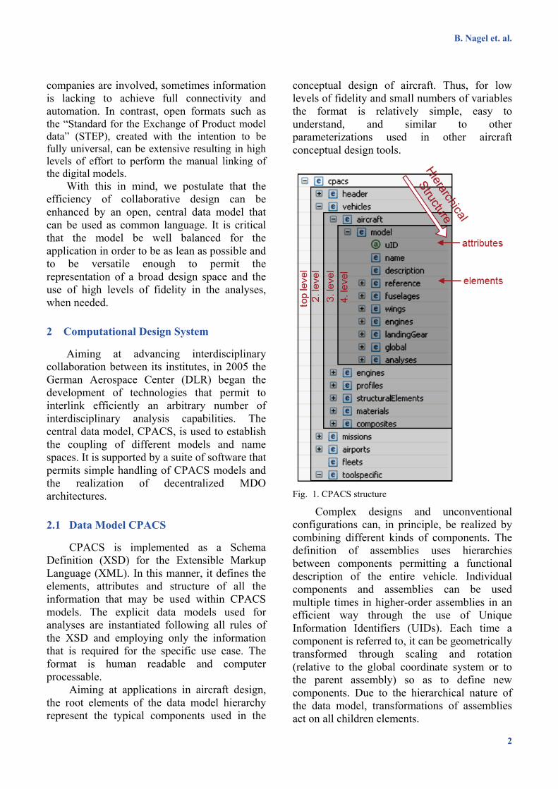
Ad-hoc collaboration among partners with advanced analysis capabilities can often be realized best by interlinking existing computational tools. Thus, decentralized architectures as shown in Fig. 2 are a natural setup for collaborative design. Beyond the technical opportunities of this concept, sustaining the permanent control over the owned software is a decisive factor for the willingness of partners to share their areas of competence and tools.
The input and output in the tool-specific data format needs to be translated into the CPACS central data model. Thus, regardless of the size of the consortium and of rearrangements of the workflow, each participant only needs to learn one new language CPACS. This is a typical example of the well-known ability of standards to turn an N2 problem (where N is the number of software packages and N2 is the number of possible connections among them) into an order N problem. Software “wrappers” need to be created for the individual tools. These wrappers contain both the translation from/to CPACS and the commands to launch the analysis application in batch mode once the necessary data is provided. Therefore, from the outside, a wrapped program looks like a single application that includes a CPACS interface. Usually the tool developers are responsible for creating the wrapper for their own tool with support from integration experts who provide an introduction to CPACS and sample implementations.
Fig. 2. Decentralized computation environment
B. Nagel et. al.
4
For convenient handling of CPACS files, the software library TIXI was developed [4]. TIXI provides an Application Programming Interface (API) for C, C++, Python, Java and FORTRAN. Based on the libxml2 library [5], TIXI permits to easily integrate XML-handling functionality into wrappers including the creation of documents, creation and deletion of nodes, addition and removal of element attributes, and reading and writing of multidimensional arrays or arrays of vectors.
Processing of geometry information stored in CPACS can be performed using the TIGL library [6]. Analogue to TIXI, TIGL permits simple access to the open source CAD software OpenCASCADE [7] specially tailored for the CPACS data model. Based on design parameters stored in CPACS, functions provided by TIGL range from computing arbitrary surface points via detecting of intersections between components to exporting geometries e.g. in IGES/VTK format.
Software for interlinking tools on different servers is becoming state of the art. Prominent commercial examples are ModelCenter [8], iSIGHT [9] and OPTIMUS [10]. Commercial products usually bundle the core functionality of control and data transfer with features like advanced process management, optimization and visualization. Since these are major areas of research in the context of collaborative design, the open source software “Remote Component Environment” (RCE) [11], which is based on ECLIPSE technologies [12], offers advantages due to increased flexibility compared to the industry-standard products. In principle, the CPACS model can be used with any coupling solution.
The conceptual aircraft design tool VAMPzero [13] was created as an open source generator for CPACS models: based on top-level aircraft requirements a conceptual aircraft is created and sized, and a CPACS model with all design data is generated as starting point for further higher-fidelity operations. An implementation of all introduced CPACS related software in RCE is available under an open source license [14].
3 Experiences
3.1 Integrated Design at DLR
DLR is a large-scale research establishment with more than 7.000 employees working in 32 institutes which are spread over 16 locations in Germany. The majority of the individual institutes are specialized in one particular discipline. Interdisciplinary collaboration between the institutes is well established in projects with typical durations of three years.
Recognizing the rising relevance of inter- disciplinary integration, DLR launched the project “Technology Integration for the Virtual Aircraft” (TIVA) in 2005. As part of the results of this effort, a first version of CPACS and dedicated tools became available, and the first distributed analysis chains were demonstrated. The successor project “Virtual Aircraft Multidisciplinary Analysis and Design Processes” (VAMP) was launched in 2010. New tools such as VAMPzero were created and further analysis capabilities where linked to the framework resulting in a seamless system for the optimization of aircraft configurations comprising tools of multiple levels of fidelity. Major outstanding research topics include how to set up optimization processes (including technical workflow management and collaboration between heterogeneous specialists [15]).
It is important to highlight that the technologies were developed aiming at creating synergies between the established, disciplinary capabilities. Thus, existing software and hardware was starting point for the development of the overall design system. The tools for disciplinary research model physical effects that are subject of research in the individual disciplines and institutes. Hence, the initially-available codes were of a very high level of fidelity and mainly in the context of preliminary design ranging up to crash analysis of fuselage sections.
The introduction of VAMPzero as a highly modular conceptual design tool containing mainly empirical correlations constituted the main step towards closing remaining gaps in the
5
Communication in Aircraft Design: Can we establish a Common Language?
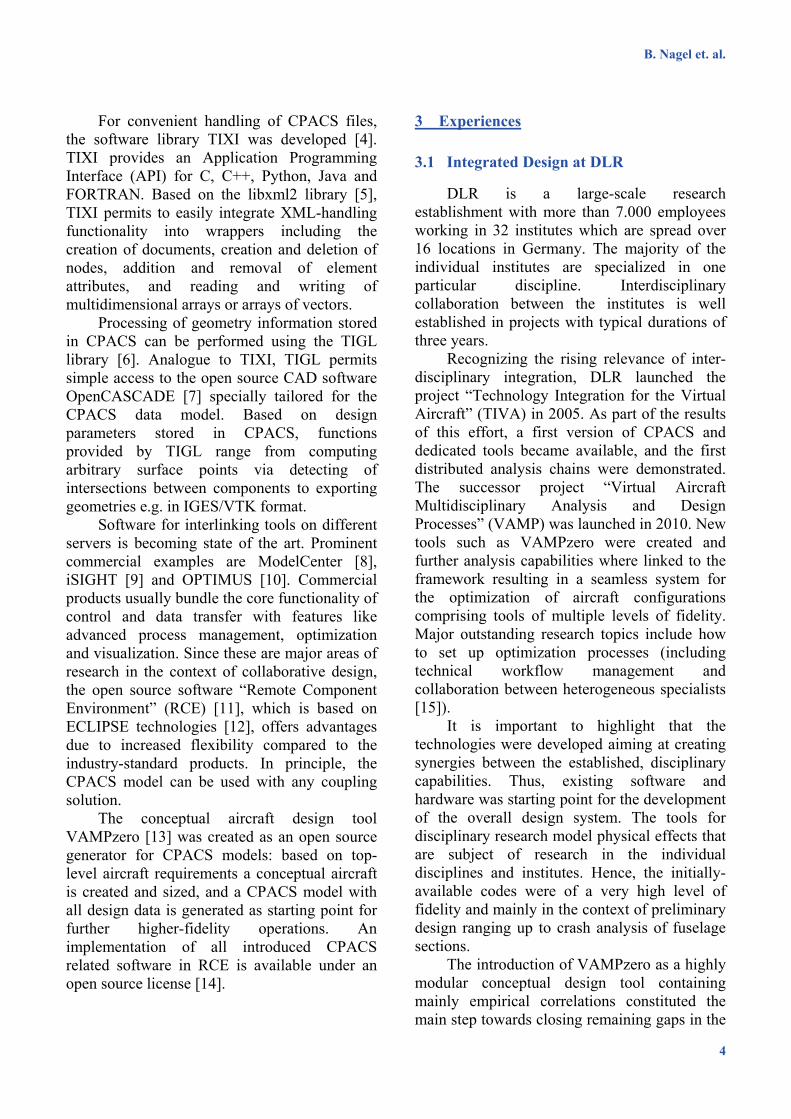
design chain, e.g. in terms of secondary masses. As a result, in its current status, the design process is based on a converging process using tools that are as fast and simple as possible. Calibration to reference data is usually the initial step before a design is optimized and, iteratively, higher fidelity tools are introduced replacing the initially-used lower fidelity measures. In the course of the VAMP project the system is used to investigate novel narrow body aircraft configurations including the integration of novel propulsion systems and resulting noise impact at a preliminary level. Fig. 3 shows an example of a workflow with an initialization branch at the left side and a convergence loop on the right hand with three parallel branches benefit computationally from the decentralized architecture. Intelligent workflow management and optimization techniques constitute actual fields of research [16].
Fig. 3. Example of VAMP workflow
In VAMP the system proved to successfully support the decentralized collaboration of 9 institutes with, typically, 25 persons actively involved. The development of a central data model was, in principle and from a technical point of view, not a significant problem. Nevertheless, the development of the system, harmonizing the different requirements in a team of complementarily-specialized persons, required significant effort. Ensuring a high intrinsic motivation was a key factor for success, especially in the early phases when the benefit for disciplinary research was not yet within reach.
Today, the system has successfully been adopted by multiple projects inside and outside DLR where interlinking a high number of different disciplines on an advanced level of fidelity is required.
3.2 Computerised Environment for Aircraft Synthesis and Integrated Optimisation Methods (CEASIOM)
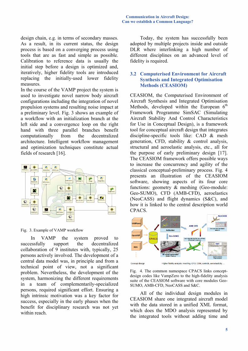
CEASIOM, the Computerised Environment of Aircraft Synthesis and Integrated Optimisation Methods, developed within the European 6th Framework Programme SimSAC (Simulating Aircraft Stability And Control Characteristics for Use in Conceptual Design), is a framework tool for conceptual aircraft design that integrates discipline-specific tools like: CAD & mesh generation, CFD, stability & control analysis, structural and aeroelastic analysis, etc., all for the purpose of early preliminary design [17]. The CEASIOM framework offers possible ways to increase the concurrency and agility of the classical conceptual-preliminary process. Fig. 4 presents an illustration of the CEASIOM software, showing aspects of its four core functions: geometry & meshing (Geo-module: Geo-SUMO), CFD (AMB-CFD), aeroelastics (NeoCASS) and flight dynamics (S&C), and how it is linked to the central description world CPACS.
Fig. 4. The common namespace CPACS links concept-design codes like VampZero to the high-fidelity analysis suite of the CEASIOM software with core modules Geo-SUMO, AMB-CFD, NeoCASS and S&C.
All of the individual design modules in CEASIOM share one integrated aircraft model with the data stored in a unified XML format, which does the MDO analysis represented by the integrated tools without adding time and
B. Nagel et. al.
6
inaccuracies from the intermediate translation steps. The approach to pass the aircraft data from CPACS to CEASIOM is made by “wrappers”. Since CPACS is based on XML technology, it is possible to make a direct adoption into the framework of the Geo-module by altering the in- and output data structure. This can be established by additional converter scripts that translate from CPACS to Geo-module and vice versa. The “wrapper” from CPACS to CEASIOM is not an end but a bridge. For those codes which are closed, indirect couplings to analysis modules (such as the S&C module in CEASIOM) are introduced through CPACS. DLR has successfully linked the initial sizing software VAMPzero [13] to CEASIOM via CPACS. An ongoing effort is also proceeding by developing a converter between the NASA parameterized geometry modeler OpenVSP [18] and CPACS to achieve the linking of VAMPzero and CEASIOM with the collaboration between DLR and KTH [19].
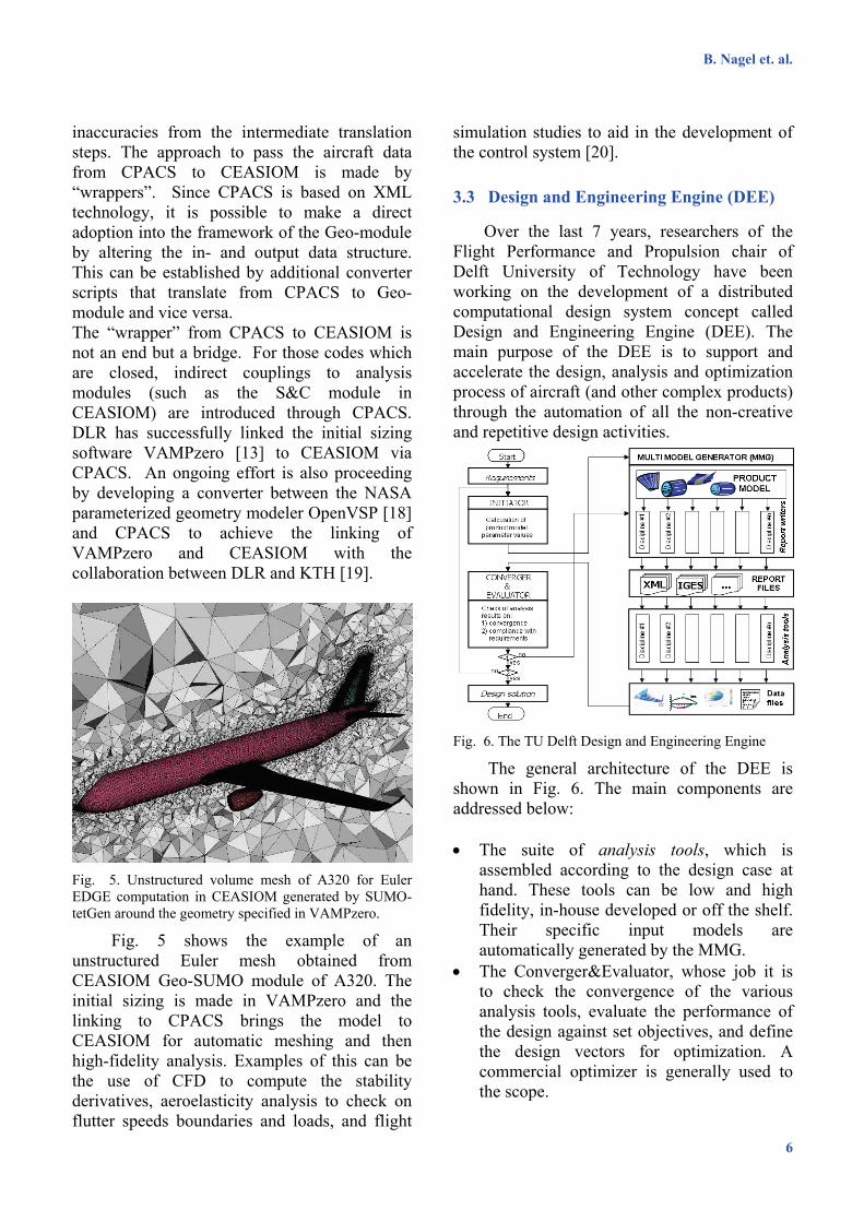
Fig. 5. Unstructured volume mesh of A320 for Euler EDGE computation in CEASIOM generated by SUMO-tetGen around the geometry specified in VAMPzero.
Fig. 5 shows the example of an unstructured Euler mesh obtained from CEASIOM Geo-SUMO module of A320. The initial sizing is made in VAMPzero and the linking to CPACS brings the model to CEASIOM for automatic meshing and then high-fidelity analysis. Examples of this can be the use of CFD to compute the stability derivatives, aeroelasticity analysis to check on flutter speeds boundaries and loads, and flight
simulation studies to aid in the development of the control system [20].
3.3 Design and Engineering Engine (DEE)
Over the last 7 years, researchers of the Flight Performance and Propulsion chair of Delft University of Technology have been working on the development of a distributed computational design system concept called Design and Engineering Engine (DEE). The main purpose of the DEE is to support and accelerate the design, analysis and optimization process of aircraft (and other complex products) through the automation of all the non-creative and repetitive design activities.
Fig. 6. The TU Delft Design and Engineering Engine
The general architecture of the DEE is shown in Fig. 6. The main components are addressed below:
• The suite of analysis tools, which is
assembled according to the design case at hand. These tools can be low and high fidelity, in-house developed or off the shelf. Their specific input models are automatically generated by the MMG.
• The Converger&Evaluator, whose job it is to check the convergence of the various analysis tools, evaluate the performance of the design against set objectives, and define the design vectors for optimization. A commercial optimizer is generally used to the scope.
7
Communication in Aircraft Design: Can we establish a Common Language?
• The communication framework, which takes care of the data and information flow between the various design and analysis tools and enables the overall design process. An agent based framework has been developed on purpose, where agents wraps the various DEE tools and enable collaboration and data exchange [23]. Alternatively, commercial workflow management systems can be used.
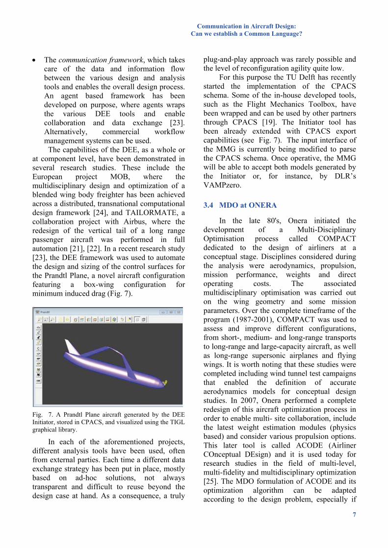
The capabilities of the DEE, as a whole or at component level, have been demonstrated in several research studies. These include the European project MOB, where the multidisciplinary design and optimization of a blended wing body freighter has been achieved across a distributed, transnational computational design framework [24], and TAILORMATE, a collaboration project with Airbus, where the redesign of the vertical tail of a long range passenger aircraft was performed in full automation [21], [22]. In a recent research study [23], the DEE framework was used to automate the design and sizing of the control surfaces for the Prandtl Plane, a novel aircraft configuration featuring a box-wing configuration for minimum induced drag (Fig. 7).
Fig. 7. A Prandtl Plane aircraft generated by the DEE Initiator, stored in CPACS, and visualized using the TIGL graphical library.
In each of the aforementioned projects, different analysis tools have been used, often from external parties. Each time a different data exchange strategy has been put in place, mostly based on ad-hoc solutions, not always transparent and difficult to reuse beyond the design case at hand. As a consequence, a truly
plug-and-play approach was rarely possible and the level of reconfiguration agility quite low.
For this purpose the TU Delft has recently started the implementation of the CPACS schema. Some of the in-house developed tools, such as the Flight Mechanics Toolbox, have been wrapped and can be used by other partners through CPACS [19]. The Initiator tool has been already extended with CPACS export capabilities (see Fig. 7). The input interface of the MMG is currently being modified to parse the CPACS schema. Once operative, the MMG will be able to accept both models generated by the Initiator or, for instance, by DLR’s VAMPzero.
3.4 MDO at ONERA
In the late 80's, Onera initiated the development of a Multi-Disciplinary Optimisation process called COMPACT dedicated to the design of airliners at a conceptual stage. Disciplines considered during the analysis were aerodynamics, propulsion, mission performance, weights and direct operating costs. The associated multidisciplinary optimisation was carried out on the wing geometry and some mission parameters. Over the complete timeframe of the program (1987-2001), COMPACT was used to assess and improve different configurations, from short-, medium- and long-range transports to long-range and large-capacity aircraft, as well as long-range supersonic airplanes and flying wings. It is worth noting that these studies were completed including wind tunnel test campaigns that enabled the definition of accurate aerodynamics models for conceptual design studies. In 2007, Onera performed a complete redesign of this aircraft optimization process in order to enable multi- site collaboration, include the latest weight estimation modules (physics based) and consider various propulsion options. This later tool is called ACODE (Airliner COnceptual DEsign) and it is used today for research studies in the field of multi-level, multi-fidelity and multidisciplinary optimization [25]. The MDO formulation of ACODE and its optimization algorithm can be adapted according to the design problem, especially if
B. Nagel et. al.
8
the objective is to calculate the optimum engine for an aircraft or if the goal is to select an engine from a database.
In parallel to these activities related to civil transports, Onera set-up in 2000 a multi-site sizing and optimization process for HALE UAV identified as UCODE (UAV COnceptual DEsign). Subsequently, UCODE has been: • Tailored to enable the design of unmanned
vehicles dedicated to aerial launch; • Extended for MALE UAV development
(based on turbocharged piston engines, turboprops or turbofans);
• Adapted for the design of a demonstrator including operational constraints. In the last few years, with the objective of
capitalizing on the different studies related to aircraft design and MDO theory, Onera initiated a review of its design processes in order to improve their flexibility and achieve an easy
exchange of specific disciplinary modules. As indicated in the classical books related
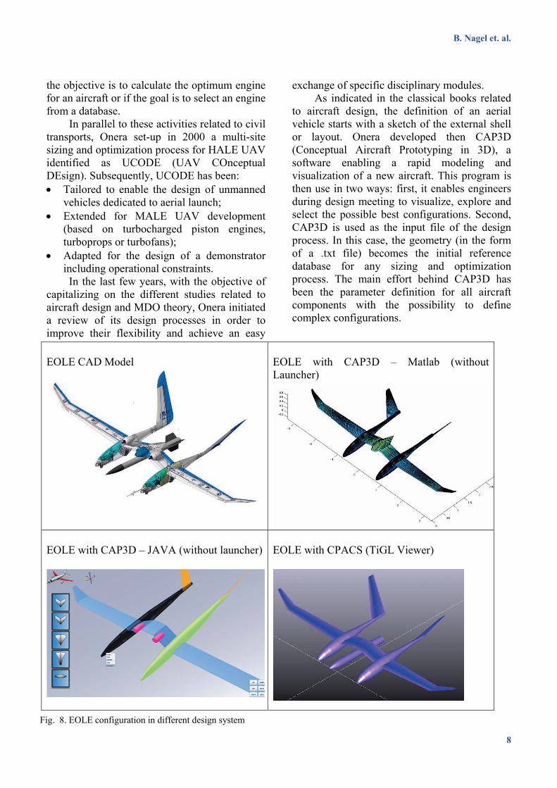
to aircraft design, the definition of an aerial vehicle starts with a sketch of the external shell or layout. Onera developed then CAP3D (Conceptual Aircraft Prototyping in 3D), a software enabling a rapid modeling and visualization of a new aircraft. This program is then use in two ways: first, it enables engineers during design meeting to visualize, explore and select the possible best configurations. Second, CAP3D is used as the input file of the design process. In this case, the geometry (in the form of a .txt file) becomes the initial reference database for any sizing and optimization process. The main effort behind CAP3D has been the parameter definition for all aircraft components with the possibility to define complex configurations.
Fig. 8. EOLE configuration in different design system
EOLE CAD Model
EOLE with CAP3D – Matlab (without Launcher)
EOLE with CAP3D – JAVA (without launcher)
EOLE with CPACS (TiGL Viewer)
9
Communication in Aircraft Design: Can we establish a Common Language?
However, the experience gathered during the ARTEMIS project [27] showed that the exchange of information between a conceptual design processes and a preliminary design process could not rely solely on the external geometry of the aircraft. Onera is then currently exploring the possibilities offered by CPACS to define a unified data model. As a first step, it has been proposed to model the EOLE flight demonstrator configuration with CPACS and to compare this experience with the CAP3D one. The outcomes will help Onera is the definition of a suited unified data model to be used in a multi-level, multi-fidelity and multi-disciplinary optimization process.
3.5 High Fidelity Models
Major uncertainties in overall aircraft performance result from coarse approximations of secondary masses. Better estimations can be obtained by more detailed analyses replacing empiricism by physics wherever possible.
The wing, for example, can be modeled in an extended way including explicit geometries of secondary structures such as high lift and control devices, pylon and landing gear. These components have been integrated into the CPACS scheme. The hierarchical structure supports complex assemblies e.g. the flap can be modeled as child of the wing and the tab of a double slotted flap as child of the main flap
In order to support structural design studies, the structural definition is not solely driven by the outer shape definition, as it is often the case in preliminary design approaches: it is represented in CPACS by so-called “component segments” which permit structural modifications and segmentations without affecting the aerodynamic shape. Movable surfaces can be treated as instances of wings and hence can contain all structural details such as stringers, ribs and areal distributions of different material systems if necessary. External components like the high lift supporting system are included parametrically. Each kinematic system is currently represented by a prototype in the schema definition. A more versatile and detailed parameterization is under development
which will result in further branches of the CPACS schema definition.
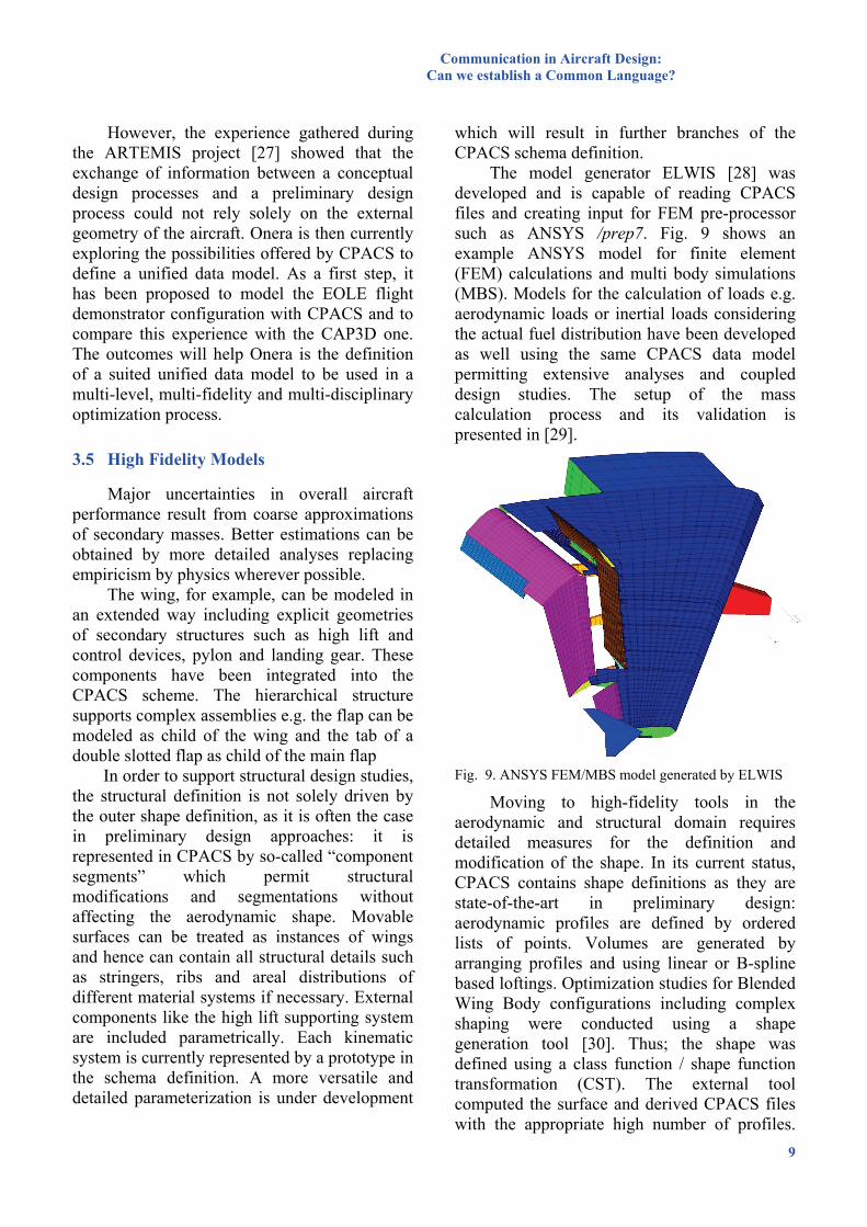
The model generator ELWIS [28] was developed and is capable of reading CPACS files and creating input for FEM pre-processor such as ANSYS /prep7. Fig. 9 shows an example ANSYS model for finite element (FEM) calculations and multi body simulations (MBS). Models for the calculation of loads e.g. aerodynamic loads or inertial loads considering the actual fuel distribution have been developed as well using the same CPACS data model permitting extensive analyses and coupled design studies. The setup of the mass calculation process and its validation is presented in [29].
Fig. 9. ANSYS FEM/MBS model generated by ELWIS
Moving to high-fidelity tools in the aerodynamic and structural domain requires detailed measures for the definition and modification of the shape. In its current status, CPACS contains shape definitions as they are state-of-the-art in preliminary design: aerodynamic profiles are defined by ordered lists of points. Volumes are generated by arranging profiles and using linear or B-spline based loftings. Optimization studies for Blended Wing Body configurations including complex shaping were conducted using a shape generation tool [30]. Thus; the shape was defined using a class function / shape function transformation (CST). The external tool computed the surface and derived CPACS files with the appropriate high number of profiles.
B. Nagel et. al.
10
Subsequently analyses were successfully conducted using previously-described tools such as Geo-SUMO and EDGE [31]. The implementation of a functional shape parameterization directly into the CPACS definition is an ongoing activity.
A dedicated challenge is managing large data sets. For assessing the climate impact, explicit mission simulations for a fleet of more than 1200 operations were linked to a climate model [32]. The resulting data with CPACS files of up to 50 MB could successfully be handled. Nevertheless; extensive data such as aerodynamic field results is stored in established file formats. CPACS contains pointers to external files and processes this information to know how to proceed with external data.
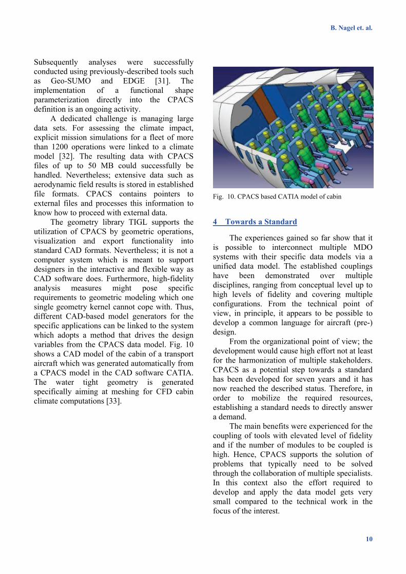
The geometry library TIGL supports the utilization of CPACS by geometric operations, visualization and export functionality into standard CAD formats. Nevertheless; it is not a computer system which is meant to support designers in the interactive and flexible way as CAD software does. Furthermore, high-fidelity analysis measures might pose specific requirements to geometric modeling which one single geometry kernel cannot cope with. Thus, different CAD-based model generators for the specific applications can be linked to the system which adopts a method that drives the design variables from the CPACS data model. Fig. 10 shows a CAD model of the cabin of a transport aircraft which was generated automatically from a CPACS model in the CAD software CATIA. The water tight geometry is generated specifically aiming at meshing for CFD cabin climate computations [33].
Fig. 10. CPACS based CATIA model of cabin
4 Towards a Standard
The experiences gained so far show that it is possible to interconnect multiple MDO systems with their specific data models via a unified data model. The established couplings have been demonstrated over multiple disciplines, ranging from conceptual level up to high levels of fidelity and covering multiple configurations. From the technical point of view, in principle, it appears to be possible to develop a common language for aircraft (pre-) design.
From the organizational point of view; the development would cause high effort not at least for the harmonization of multiple stakeholders. CPACS as a potential step towards a standard has been developed for seven years and it has now reached the described status. Therefore, in order to mobilize the required resources, establishing a standard needs to directly answer a demand.
The main benefits were experienced for the coupling of tools with elevated level of fidelity and if the number of modules to be coupled is high. Hence, CPACS supports the solution of problems that typically need to be solved through the collaboration of multiple specialists. In this context also the effort required to develop and apply the data model gets very small compared to the technical work in the focus of the interest.
11
Communication in Aircraft Design: Can we establish a Common Language?
The following aspects are critical for the implementation of a standard for communication in aircraft design: • Public availability of all technical
information. • Availability of training material, training
courses and technical help. • Effort for learning the standard significantly
smaller compared to the technical problem to be solved.
• Possibility to use the model without charge. • Continuance of conventions. • Extendibility towards specific use cases. • Structured development process with
predictable cycles. • Steering authority which coordinates the
development process. • Possibility of standard to be adopted as
“own” instrument by users. • Possibility to participate in development and
in control of the standard. Perhaps steering by a committee following the idea of the World Wide Web Consortium (W3C).
• High propagation of the standard CPACS is used to generate experiences in
the coupling of different analysis codes and setting up wide MDO systems at low effort. The gained experiences are used to continuously enhance the system.
The achieved technical status and the availability of all critical software components under an open source license has enabled users to obtain significant benefits resulting from simplified collaboration facilitated by the use of a standard.
However, in order to create a standard, a larger group sharing these interests needs to be formed. Currently CPACS is used to demonstrate potential benefits and attract potential participants. For wider acceptance as a standard, the establishment of a neutral steering committee is under discussion. The experiences gained with CPACS and some technical solutions are good starting points for setting a standard.
5 Conclusion
A standardized data model to be used as common language for the communication in aircraft design could have a signficant impact on the efficiency of collaborative research and design efforts. The Common Parametric Aircraft Configuration Scheme (CPACS) was suggested as one potential step towards a unified data model and was used to test interfaces between different MDO systems. The experiences gained so far are promising. Beyond technical solutions to be found, establishing a standard is an organizational challenge that can only be mastered if the required resources can be mobilized.
CPACS is a lean data model which is tailored for the application in the field of aircraft design ranging up to advanced pre design and MDO levels. Thus, it does not offer as high flexibility, as high level of detail, or life-cycle information as current PDM/PLM solutions provide. However; these limitations enable simplicity and low-effort integration of the standard, which is key-requirement in agile collaboration setups. CPACS is well suited to complement enterprise data handling systems.
Due to CPACS’ hierarchic structure, handling of variable-fidelity information is supported. However, interlinking the different models and optimization techniques for multi-level, decentralized workflows remain subjects of research. The utilization of an open-source framework and optimization software offers maximum freedom for dedicated investigations. Nevertheless, the implementation of CPACS in commercial optimization systems is possible without limitations and has been demonstrated [15].
Moving towards higher levels of fidelity, the generation of initial models becomes challenging due to the amount of design data. One example is the explicit geometric specification of stiffeners in the conic parts of aircraft fuselages. This is the native domain of Knowledge Based Engineering software (KBE) such as TU Delft’s MMG which creates a product model with all its part-whole relationships and hierarchies. CPACS files can be derived from internal product representations
B. Nagel et. al.
12
and complemented by results and process information. Furthermore, as standardized language, it enables low-effort exchange of KBE models across the borders of individual KBE systems and permits to efficiently link analysis models to the KBE product model. Hence, CPACS and KBE are complementary technologies.
In the experiences gained, a common data model was proven to strongly support trans-disciplinary integration. The described collaboration was not based on external funding but motivated by the technical benefits resulting from collaboration. The capability to efficiently team up enables more collaborative ways of working. As a result, new fields of research become evident such as optimization and decomposition techniques for MDO systems with high numbers of disciplines as they can be established more easily. As an item of increasing importance, the interpretation of results from very complex systems is becoming critical and certainly cannot be performed by individuals but requires the collaboration of specialists. Alternatives for collaborative environments that include both tools and humans have been proposed by multiple research groups and will eventually constitute the 3rd generation of MDO tools. The capability of efficiently building complex workflows is a precondition to investigate this next level of MDO.
Acknowledgments
The authors would like to thank L. Cöllen for her work in the testing of the CPACS format towards its use in Onera's conceptual design MDO process and in KTH’s CEASIOM environment.
References
[1] D. Böhnke “Common Parametric Aircraft Configuration Schema” http://code.google.com/p/cpacs/
[2] D. Böhnke, M. Litz, B. Nagel, S. Rudolph, Evaluation of Modeling Languages for Preliminary Airplane Design in Multidisciplinary Design Environments, German Aeronautics and Space Congress, DLRK, 2010, Hamburg
[3] C. M. Liersch, M. Hepperle, A distributed toolbox for multidisciplinary preliminary aircraft design, CEAS Aeronautical Journal (2011) 2:57–68.
[4] M. Litz, A. Bachmann, M. Kunde, “TIVA XML Interface,” http://code.google.com/p/tixi/
[5] http://www.xmlsoft.org/ [6] M. Litz, A. Bachmann, M. Kunde, “TIVA
Geometric Library,” http://code.google.com/p/tigl/ [7] http://www.opencascade.org/ [8] http://www.phoenix-int.com/software/phx-
modelcenter.php [9] http://www.3ds.com/products/simulia/ [10] http://www.noesissolutions.com/Noesis/optimus-
details [11] D. Seider, M. Litz, A. Schreiber, P. M. Fischer, A.
Gerndt, Open Source Software Framework for Applications in Aeronautics and Space, IEEE Aerospace Conference, 2012.
[12] http://www.eclipse.org/ [13] D. Böhnke “VAMPzero Conceptual Aircraft Design
and Synthesis Code” http://code.google.com/p/vampzero/
[14] http://software.dlr.de/ [15] T. Zill, D. Böhnke and B. Nagel, Preliminary Aircraft
Design in a Collaborative Multidisciplinary Design Environment, 11th AIAA Aviation Technology, Integration, and Operations (ATIO) Conference, including the AIAA, 2011, Virginia Beach, VA, USA.
[16] T. Zill, P. D. Ciampa, B. Nagel, Multidisciplinary Design Optimization in a Collaborative Distributed Aircraft Design System, 50th AIAA Aerospace Sciences Meeting (ASM) 2012, Nashville, USA
[17] http://www.ceasiom.com/ [18] http://www.openvsp.org/ [19] T. Pfeiffer, B. Nagel, D. Böhnke, A.Rizzi, M.
Voskuijl, Implementation of a Heterogeneous, Variable-Fidelity Framework for Flight Mechanics Analysis in Preliminary Aircraft Design, German Aeronautics and Space Congress, DLRK, 2011, Bremen, Germany.
[20] A. Rizzi, M. Zhang, B. Nagel, D. Böhnke, Towards a Framework with Unified Geometry Management for Virtual Aircraft Design, AIAA Aerospace Sciences Meeting, 2012.
13
Communication in Aircraft Design: Can we establish a Common Language?
[21] G. La Rocca, MJL. van Tooren, Knowledge-based engineering to support aircraft multidisciplinary design and optimization. Proceedings of the Institution of Mechanical Engineering, Part G: Journal of Aerospace Engineering, 224 (2010) 1041-1055.
[22] G La Rocca, THM Langen, YHA Brouwers, The design and engineering engine. Towards a modular system for collaborative aircraft design. in: 28th International Congress of the Aeronautical Sciences, Brisbane, AU, 2012.
[23] JPTJ Berends, MJL van Tooren, Design of a multi-agent task environment framework to support multidisciplinary design and optimisation. in: 45th AIAA Aerospace Sciences Meeting and Exhibit, AIAA, Reno, NV, 2007
[24] A. Morris, G. La Rocca, P Arendsen, M Laban, R Voss, H Hönlinger. Mob - a european project on multidisciplinary design optimisation. in: 24th ICAS Congress, ICAS, Yokohama, Japan, 2004.
[25] D. van Ginneken, M. Voskuijl, MJL. Van Tooren, A. Frediani, Automated Control Surface Design and sizing for the Prandltl Plane, in: 51st AIAA/ASME/ASCE/AHS/ASC Structures, Structural Dynamics, and Materials Conference, Orlando, Florida, 2010.
[26] C. Blondeau1, G. Carrier, S. Defoort, J. Hermetz, P. Schmollgruber, "Toward multi-level, multi-fidelity, multi-disciplinary optimization at Onera", RTO-MP-AVT-173, 2011
[27] J. Hermetz, J. Ledogar, E. Rantet, "EOLE, an innovative flying test scale demonstrator for air-launch autonomous systems", ICAS Congress, ICAS, Brisbane, Australia, 2012
[28] F. Dorbath, B. Nagel, V. Gollnick, A knowledge Based Approach for Automated Modelling of Extended Wing Structures in Preliminary Aircraft Design, German Aeronautics and Space Congress, DLRK, 2011, Bremen, Germany.
[29] F. Dorbath, B. Nagel, V. Gollnick, A knowledge based approach for extended physics-based wing mass estimation in early design stages, 28th International Congress of the Aeronautical Sciences, Brisbane, AU, 2012.
[30] P. D. Ciampa, T. Zill, B. Nagel, CST parametrization for unconventional aircraft design optimization, International Council of the Aerospace Sciences (ICAS) 2010, Nice, France
[31] P. D. Ciampa, T. Zill, B. Nagel, Aeroelastic Design and Optimization of Unconventional Aircraft Configurations in a Distributed Design Environment, 53rd AIAA Structures, Structural Dynamics, and Materials Conference, Honolulu, USA
[32] A. Koch, B. Lührs, K. Dahlmann, F. Linke, V. Grewe, M. Litz, M., Plohr, U. Schumann, V. Gollnick, B. Nagel, Climate impact assessment of varying cruise flight altitudes applying the CATS simulation approach, 3rd International Conference of the European Aerospace Societies, (CEAS), Venice, Italy (2011).
[33] J. Fuchte, S. Rajkowski, A. Wick, Rapid Model Creation for Cabin CFD Simulations, Aircraft Systems Technology, AST, Hamburg, Germany, 2011
[34] D. Böhnke, B. Nagel, V. Gollnick, An Approach to Multi-Fidelity in Conceptual Aircraft Design in a Distributed Design Environment, IEEE Aerospace Conference, 2011.
Copyright Statement
The authors confirm that they, and/or their company or organization, hold copyright on all of the original material included in this paper. The authors also confirm that they have obtained permission, from the copyright holder of any third party material included in this paper, to publish it as part of their paper. The authors confirm that they give permission, or have obtained permission from the copyright holder of this paper, for the publication and distribution of this paper as part of the ICAS2012 proceedings or as individual off-prints from the proceedings.