Embed Size (px)
Citation preview
FACULT Y OF
COMPUTER SCIENCE
Communication and Networked Systems
Bachelor Thesis
3D Scan Applications in Logistics:Using CoAP with RGB-D Cameras
Fabian Hüßler
Supervisor: Prof. Dr. rer. nat. Mesut GüneşAssisting Supervisor: MSc. Marian Buschsieweke
Institute for Intelligent Cooperating Systems, Otto-von-Guericke-University Magdeburg
August 6, 2020

Abstract
Abstract
The embedded devices which form the Internet of Things (IoT) experience a rapid devel-opment in increasing processing power and decreasing chip sizes and prices. Future homeswill be equipped with smart network interoperable devices, which will communicate overvarious network protocol stacks. In the fields of home- and industrial automation, camerasproviding color and depth information prove to be very useful in many applications such asface recognition, pose tracking or environmental 3D scanning.The Constraint Application Protocol (CoAP) is a popular IoT protocol for low power andlossy wireless networks. CoAP is commonly used to transmit small sized sensor data, whileimage sizes may be in the order of MB. This thesis aims to provide a comprehensive Appli-cation Programming Inteface (API) to make camera resources from the state of the arts lowcost Intel RealSense RGB-D (color and depth) cameras retrievable for a CoAP client. Italso gives an insight in basic camera concepts and the use of cameras for logistic companies.As an example, the provided CoAP client computes the object dimensions of received pointcloud data and may show the color image and the depth image in grayscale values. Theclient may monitor a resource, while it repeats the initial request. The application is testedin several test cases, which show that CoAP can be used for simple 3D scan applications,but packet drops become a bottleneck because with default protocol parameters (NSTART =1), CoAP effectively becomes a “stop and wait” protocol. The median to transmit a colorimage with a resolution of 1280x720 pixels over a wireless network is 14.6 s. The median totransmit a full point cloud from a depth image with 1280x720 pixels over a wireless networkcould be reduced to 16 s.

Contents
List of Figures vii
List of Tables ix
Listings xi
Acronyms xiii
Glossary xv
1 Introduction 11.1 Motivation . . . . . . . . . . . . . . . . . . . . . . . . . . . . . . . . . . . . 21.2 Thesis Structure . . . . . . . . . . . . . . . . . . . . . . . . . . . . . . . . . 3
2 Related Work 5
3 Thesis Contribution 73.1 Application Scope . . . . . . . . . . . . . . . . . . . . . . . . . . . . . . . . 73.2 Architecture . . . . . . . . . . . . . . . . . . . . . . . . . . . . . . . . . . . . 83.3 Implementation . . . . . . . . . . . . . . . . . . . . . . . . . . . . . . . . . . 9
3.3.1 The CoAP Library . . . . . . . . . . . . . . . . . . . . . . . . . . . . 103.3.2 The Camera . . . . . . . . . . . . . . . . . . . . . . . . . . . . . . . . 113.3.3 Resource API . . . . . . . . . . . . . . . . . . . . . . . . . . . . . . . 123.3.4 3D-Transformation . . . . . . . . . . . . . . . . . . . . . . . . . . . . 193.3.5 Image Processing . . . . . . . . . . . . . . . . . . . . . . . . . . . . . 21
3.4 Experiments . . . . . . . . . . . . . . . . . . . . . . . . . . . . . . . . . . . . 233.4.1 Test Case 1: (Color, 640x480, local) . . . . . . . . . . . . . . . . . . 233.4.2 Test Case 2: (Color, 1280x720, local) . . . . . . . . . . . . . . . . . . 243.4.3 Test Case 3: (libcoap, 2764810 Byte, local) . . . . . . . . . . . . . . 243.4.4 Test Case 4: (Color, 1280x720, 1-Hop) . . . . . . . . . . . . . . . . . 243.4.5 Test Case 5: (Embedded, Color, 1280x720, 1-Hop) . . . . . . . . . . 243.4.6 Test Case 6: (Point Cloud, 640x480, local) . . . . . . . . . . . . . . . 253.4.7 Test Case 7: (Point Cloud, 1280x720, local) . . . . . . . . . . . . . . 253.4.8 Test Case 8: (libcoap, 10032012 Byte, local) . . . . . . . . . . . . . . 253.4.9 Test Case 9: (Point Cloud, 1280x720, 1-Hop) . . . . . . . . . . . . . 263.4.10 Test Case 10: (Point Cloud, Decimation, 1280x720, 1-Hop) . . . . . 26
vi
3.4.11 Test Case 11: (Embedded, Point Cloud, Decimation, 1280x720, 1-Hop) 26
4 Thesis Outcome 274.1 Evaluation . . . . . . . . . . . . . . . . . . . . . . . . . . . . . . . . . . . . . 27
4.1.1 Evaluation Test Case 1: (Color, 640x480, local) . . . . . . . . . . . . 274.1.2 Evaluation Test Case 2: (Color, 1280x720, local) . . . . . . . . . . . 284.1.3 Evaluation Test Case 3: (libcoap, 2764810 Byte, local) . . . . . . . . 284.1.4 Evaluation Test Case 4: (Color, 1280x720, 1-Hop) . . . . . . . . . . 294.1.5 Evaluation Test Case 5: (Embedded, Color, 1280x720, 1-Hop) . . . . 294.1.6 Evaluation Test Case 6: (Point Cloud, 640x480, local) . . . . . . . . 294.1.7 Evaluation Test Case 7: (Point Cloud, 1280x720, local) . . . . . . . 304.1.8 Evaluation Test Case 8: (libcoap, 10032012 Byte, local) . . . . . . . 304.1.9 Evaluation Test Case 9: (Point Cloud, 1280x720, 1-Hop) . . . . . . . 314.1.10 Evaluation Test Case 10: (Point Cloud, Decimation, 1280x720, 1-Hop) 314.1.11 Evaluation Test Case 11: (Embedded, Point Cloud, Decimation, 1280x720,
1-Hop) . . . . . . . . . . . . . . . . . . . . . . . . . . . . . . . . . . . 324.1.12 Evaluation Charts . . . . . . . . . . . . . . . . . . . . . . . . . . . . 32
5 Conclusion 435.1 Summary . . . . . . . . . . . . . . . . . . . . . . . . . . . . . . . . . . . . . 435.2 Future Work . . . . . . . . . . . . . . . . . . . . . . . . . . . . . . . . . . . 44
Bibliography 45
Appendix 48A.1 JSON format of resource ”/cams/<serial nr.>/depth-settings“ . . . . . . . 49A.2 JSON format of resource ”/cams/<serial nr.>/color-settings“ . . . . . . . . 49A.3 JSON format of resource ”/cams/<serial nr.>/application-config“ . . . . . 49A.4 JSON format of resource ”/cams/<serial nr.>/3d-transformation“ . . . . . 50A.5 JSON format of resource ”/cams/<serial nr.>/advanced-config“ . . . . . . 50
List of Figures
3.1 Application resource tree . . . . . . . . . . . . . . . . . . . . . . . . . . . . 93.2 Packet field layout of color, depth and point cloud packets . . . . . . . . . . 133.3 CoAP message flow of a successful resource creation of the color resource for
a certain camera . . . . . . . . . . . . . . . . . . . . . . . . . . . . . . . . . 143.4 CoAP message flow of a successful retrieval of all point clouds from all cam-
eras connected to a single endpoint . . . . . . . . . . . . . . . . . . . . . . . 153.5 CoAP message flow of a successfully initiated transmission of a color image 153.6 CoAP message flow of a successfully initiated transmission of a depth image 163.7 CoAP message flow of a successfully initiated transmission of a point cloud 163.8 CoAP message flow of a successful retrieval of the color-settings resource of
a certain camera . . . . . . . . . . . . . . . . . . . . . . . . . . . . . . . . . 173.9 CoAP message flow of a successful update of the color-settings resource of a
certain camera . . . . . . . . . . . . . . . . . . . . . . . . . . . . . . . . . . 173.10 Recommended post processing order of a depth frame from a RealSense D400
camera . . . . . . . . . . . . . . . . . . . . . . . . . . . . . . . . . . . . . . . 183.11 CoAP message flow of a successful retrieval of the advanced-config resource
of a certain camera . . . . . . . . . . . . . . . . . . . . . . . . . . . . . . . . 193.12 CoAP message flow of a successful update of the advanced-config resource of
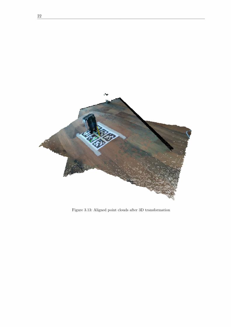
a certain camera . . . . . . . . . . . . . . . . . . . . . . . . . . . . . . . . . 193.13 Aligned point clouds after 3D transformation . . . . . . . . . . . . . . . . . 22
4.1 Box plot of all transmission times for all test cases . . . . . . . . . . . . . . 334.2 Box plot of all transmission times for all color related test cases . . . . . . . 344.3 Box plot of all transmission times for all point cloud related test cases . . . 344.4 Box plot of moving average transmission times for all test cases . . . . . . . 354.5 Bar chart of maximum resident set size for all test cases . . . . . . . . . . . 364.6 Bar chart of instruction references . . . . . . . . . . . . . . . . . . . . . . . 374.7 Bar chart of I1 miss rate . . . . . . . . . . . . . . . . . . . . . . . . . . . . . 384.8 Bar chart of data references . . . . . . . . . . . . . . . . . . . . . . . . . . . 394.9 Bar chart of D1 miss rate . . . . . . . . . . . . . . . . . . . . . . . . . . . . 404.10 Bar chart of LLd miss rate . . . . . . . . . . . . . . . . . . . . . . . . . . . . 41

List of Tables
3.1 Allowed Application Resource Methods . . . . . . . . . . . . . . . . . . . . 103.2 Hardware that has been used in all test cases . . . . . . . . . . . . . . . . . 23
4.1 Statistic of transmission times for test case 1: (Color, 640x480, local) . . . . 284.2 Statistic of transmission times for test case 2: (Color, 1280x720, local) . . . 284.3 Statistic of transmission times for test case 3: (libcoap, 2764810 Byte, local) 284.4 Statistic of transmission times for test case 4: (Color, 1280x720, 1-Hop) . . 294.5 Statistic of transmission times for test case 5: (Embedded, Color, 1280x720,
1-Hop) . . . . . . . . . . . . . . . . . . . . . . . . . . . . . . . . . . . . . . . 294.6 Statistic of transmission times for test case 6: (Point Cloud, 640x480, local) 304.7 Statistic of transmission times for test case 7: (Point Cloud, 1280x720, local) 304.8 Statistic of transmission times for test case 8: (libcoap, 10032012 Byte, local) 304.9 Statistic of transmission times for test case 9: (Point Cloud, 1280x720, 1-Hop) 314.10 Statistic of transmission times for test case 10: (Point Cloud, Decimation,
1280x720, 1-Hop) . . . . . . . . . . . . . . . . . . . . . . . . . . . . . . . . . 314.11 Statistic of transmission times for test case 11: (Embedded, Point Cloud,
Decimation, 1280x720, 1-Hop) . . . . . . . . . . . . . . . . . . . . . . . . . . 32

Listings
A.1 Expected payload encoding of resource “/cams/<serial nr.>/depth-settings” 49A.2 Expected payload encoding of resource “/cams/<serial nr.>/color-settings” 49A.3 Expected payload encoding of resource “/cams/<serial nr.>/application-
config” . . . . . . . . . . . . . . . . . . . . . . . . . . . . . . . . . . . . . . . 49A.4 Expected payload encoding of resource “/cams/<serial nr.>/3d-transformation” 50A.5 Expected payload encoding of resource “/cams/<serial nr.>/advanced-config” 50

Acronyms
API Application Programming Inteface. iii, 2, 7, 9, 10, 20, 43ASCII American Standard Code for Information Interchange. 12
CoAP Constraint Application Protocol. iii, 1–3, 5, 7–11, 14, 15, 18, 23–26, 43, 44
DTLS Datagram Transport Layer Security. 1, 2, 10
FPS Frames per Seconds. 12, 16, 17FRD Fully Distributed Resource Discovery. 5
HTTP Hyper Text Transfer Protocol. 1, 2, 5
ICP Iterative Closest Point. 14, 17IMU Inertial Measurement Unit. 11IoT Internet of Things. iii, 1, 5, 7
JSON JavaScript Object Notation. 11, 16–18, 21
MQTT Message Queuing Telemetry Transport. 1–3, 8, 43MQTT-SN MQTT for Sensor Networks. 1, 2MTU Maximum Transmission Unit. 5
NTP Network Time Protocol. 8
PRD Proactive Resource Discovery. 5
REST Representational State Transfer. 1
SLAM Simultaneous Localization and Mapping. 5SVD Single Value Decomposition. 14
TCP Transmission Control Protocol. 2, 43

xiv
UDP User Datagram Protocol. 1, 2, 8URI Unified Resource Identification. 1, 2, 10, 12, 16
Glossary
E-Commerce Commerce over the Internet. 1Extrinsic Parameters Rotation matrix and translation vector. 21
Focal Length Distance from the Principal Point to the camera sensor. 20
Industry 4.0 4th industrial revolution - Automated customizable and self-regulated manu-facturing processes with the help of IT and networked systems. 1
Intrinsic Parameters Camera specific values - Focal Length Principal Point Lense Distor-tion and Distortion Model. 20
Principal Point Point on the image plane onto which the perspective center is projected.20
RealSense RGB-D camera series from Intel. iii, 2, 6, 7, 9, 11, 16–18, 20, 21, 23, 26, 43RGB-D Camera that provides color (RGB) and depth (D) information with each pixel..
iii, 1–3, 5, 7, 43

CHAPTER 1
Introduction
There are more devices connected to the IoT than people living on earth and prognosispredict that by 2025 it will be more than 75 billions [1]. Cameras are an essential part ofIndustry 4.0 and the world of smart devices. Sensors to capture visual information equiprobots with the most important sense of humans, the sight. While industrial laser scannersare a costly purchase, modern depth cameras may offer an acceptable alternative [2]. Withthe gain of image information from color and depth images, machines are able to completecomplex tasks, e.g. estimating the load status of a truck or 3D reconstruction.Industry 4.0 is significantly driven by the IoT [3] and thus takes advantage of networkprotocols for constraint devices, such as Message Queuing Telemetry Transport (MQTT) [4],CoAP [5] or MQTT for Sensor Networks (MQTT-SN) [6] to meet the demands of constraintdevices with limited memory and processing power. When it comes to large payloadsbeyond the size of simple temperature and humidity data, further challenges appear likethe negotiation of block sizes in a network of heterogenous devices, packet loss and latency.With the success of E-Commerce, logistic companies like DHL or UPS have to deal with acontinuous growth of packet deliveries [7]. Prices are often calculated by package weight andsize. Hence, logistic companies profit from an automatic and reliable estimation of packetand load sizes in their workflow. Packets usually have a barcode or a QR code attachedthat must be scanned to coordinate the delivery process. RGB-D sensors may serve bothpurposes. The distribution of RGB-D data from a camera in a constraint network requiresan appropriate network protocol.CoAP is a popular IoT protocol which has originally been proposed by Shelby et al. in RFC7252 [5]. CoAP runs over User Datagram Protocol (UDP) and has been designed to makeresources in constraint networks easily accessible through the web. CoAP is closely relatedto Hyper Text Transfer Protocol (HTTP) [8], as they share common request methods andresponse codes. CoAP and HTTP are conform to the Representational State Transfer(REST) [9] architecture. Resources are uniquely identifiable by their Unified ResourceIdentification (URI) [10] and each request must be processed independently by the server.Communication over CoAP can also be secured by a Datagram Transport Layer Security(DTLS) layer. Similar to the https:// scheme, there exists the DTLS secured coaps://scheme. Due to the unreliable message delivery of UDP, CoAP introduces the possibility
2
to initiate a reliable communication as indicated by the message type. Reliable messagesare marked as confirmable and become retransmitted with an exponential backoff until amatching acknowledgement is received or the number of maximum retransmissions wouldbe exceeded. Unlike CoAP, MQTT runs over Transmission Control Protocol (TCP), thusit already guarantees that messages arrive in order and reliable. The MQTT protocol mayseem to be the better choice if large payloads must be transmitted. This thesis investigatesif CoAP could be used with RGB-D cameras. Specifically a resource API is presented thatprovides a RESTful interface to the Intel RealSense D400 cameras.
1.1 Motivation
While MQTT has prevailed for many companies, the use of CoAP is motivated by con-venience, rather than performance. The most convenient user interface probably is a webbrowser, as almost everyone uses it daily with mobile or stationary devices and is able tooperate it. For employees in a logistics center or for any kind of customer, it would be easyto retrieve sensor information over a web browser. To build a bridge between web browsersand CoAP endpoints with camera interface, HTTP-CoAP and CoAP-HTTP proxies couldmap messages between both protocols. The mapping between CoAP and HTTP is best ex-plained in RFC8075 [11]. CoAP may be a choice to transmit camera data in a live streambecause it runs over UDP. Therefore, cameras could be used for monitoring.The CoAP multicast feature is an easy solution to aggregate camera data if cameras aredistributed across multiple endpoints. In practice, multiple cameras are often used for 3Dreconstruction [12] or if the scan area cannot be covered by the field of view of only onecamera. Endpoints in constraint networks are more affected by failure rates. If cameras aredistributed over multiple endpoints, services could be held up at least partially or anothercamera could be calibrated to substitute the failed endpoint. Processing also becomes morebalanced when one endpoint does not have to serve requests for more than one camera.Although it is not trivial to map a HTTP request to a CoAP multicast request and wait formultiple responses because HTTP lacks multicast support, it is mentioned in RFC8075 [11].CoAP group communication is well defined in RFC7390 [13].CoAP integrates a resource discovery mechanism that makes it easy for clients to discovernew cameras. The resource discovery can be used in combination with multicast to getall resources from multiple endpoint with a single request. Clients may further limit theresponse payload size while they filter by the desired type of resource. For example to filterby group resources, a client appends rt=core.gp to the URI query in a discovery request.A resource directory [14] is a further resource discovery improvement in a network withmany nodes and many resources. The resource directory is a central point where nodes aresupposed to register their resources and update them periodically.Comparisons with MQTT-SN have shown that CoAP needs more time to complete a regu-larly scheduled single hop transmission and that messages arrive less reliable in a multi hopscenario but energy consumption is lower [15]. In the scenario presented in [16], MQTT-SNhad a 30% better average transmission time than CoAP. Another publication showed thatCoAP may outperform MQTT when the packet loss rate is greater or equal to 25%. Themessage overhead generated with CoAP is smaller than that of MQTT, as long as payloadsizes do not exceed about 320 B [17].
3
1.2 Thesis Structure
The remaining of this thesis is structured as follows.The next section puts this thesis into a context of existing work. Chapter 3 first givesan overview of the application in Section 3.1 that is contributed with this thesis. ThenSection 3.2 shows the application- and CoAP resource architecture. Section 3.3 stateshow the resource semantics have been implemented and what they do exactly. After that,Section 3.3.5 tells what image processing is done to complete the application task. Thisthesis includes experiments in Section 3.4 that test the performance of the application.Following, experiments are evaluated in Section 4.1. Finally, a conclusion will be drawn inSection 5.1 if CoAP could be used to transmit RGB-D camera data in logistic applicationfields.

CHAPTER 2
Related Work
Since the proposal of CoAP in 2014, a lot of extending work has been put into it. Somecommon and important extensions are the block-wise transfer [18] to make it possible totransmit large payloads that exceed the Maximum Transmission Unit (MTU) of CoAP,without IP fragmentation, and the OBSERVE option [19] that extends CoAP with a pushmechanism, based on client subscriptions. Further research was done to facilitate CoAPgroup communication [13] and guidelines to map between HTTP and CoAP were pro-posed [11]. A lot of research was done to ease resource discovery. There are centralizedProactive Resource Discovery (PRD) [20] solutions with a resource directory and there areFully Distributed Resource Discovery (FRD) [21] approaches. In PRD, the resource di-rectory sends advertisements so that new nodes may become aware of it very quickly. InFRD, resource descriptions are propagated by a flooding algorithm. CoAP has becomevery popular in the IoT, hence there are a lot of implementations in different languages.A performance analysis of several CoAP implementations has been conducted by MarkerIglesias-Urkia et al. [22]. Their tests showed that libcoap is one of the fastest libraries.Companies with focus on industrial automation are using RGB-D cameras to develop newapplications for their customers in the logistics sector. For example, Thorsis Technologiesin collaboration with the Fraunhofer institution in Magdeburg have developed a frameworkfor different RGB-D cameras [23]. It provides different applications, like simple packagescan, scan of euro pallets and load supervision in a truck.In robotics, RGB-D cameras are frequently used to perform Simultaneous Localization andMapping (SLAM). The robot’s task in SLAM is to construct a 3D map of it’s environmentand capture the path on which it was moving. Endres et al. [24] presented one of the firstRGB-D SLAM systems, where the only sensor has been a Microsoft Kinect v1.There are different approaches how cameras calculate depth values. An early techniquewas structured light [25]. Structured light imposes that an irregular but known infraredpattern is traced into the scene and an infrared camera observes the projected pattern.Depth values are triangulated from the disparity of the known pattern and the projectedpattern. While the Microsoft Kinect v1 works with structured light, Kinect v2 measuresthe Time-of-Flight [26] for a laser that is traced into the scene and reflected back to thecamera. A comparison of Kinect v1 and Kinect v2 has been done by Wasenmüller et al. [27].
6
They concluded that the Kinect v2 delivers more accurate depth values, even across longerdistances but is more affected by temperature than the Kinect v1 camera. They have alsonoted that multiple structured light cameras interfere each other. The cameras used forthis thesis are Intel’s RealSense D400 [28] depth cameras, which compute depth informationfrom stereo vision [29]. For stereo vision, two cameras must produce rectified images ofthe same scene which means that a pixel in one image must correspond to a pixel in theother image, where the corresponding pixel is only shifted in horizontal direction. Findingcorresponding pixels can be hard in textureless scenes, thus Intel’s cameras also include aninfrared projector [30] to produce an artificial texture. Carfagni et al. [31] have comparedthe model D415 with Intel’s previous generation of depth cameras, with regards to shortrage depth quality. They found the D415 to be more precise. Intel has published a collectionof papers, regarding their D400 camera series. These papers include methods for camerafine tuning [32], power over Ethernet [33], image post processing [34], the use of multiplecameras [35], an explanation of the infrared projectors [30] and a guide to perform a cameracalibration [36].
CHAPTER 3
Thesis Contribution
This chapter presents the results that could be achieved with the work on this thesis. Firstly,the implementation scope is given in Section 3.1. Following, the application architectureis described and the structure of the CoAP resource API is presented in Section 3.2. Asa main part, Section 3.3 shows implementation details of the utilized CoAP library andthe camera interface and explains CoAP resource semantics. It also puts a focus on imageprocessing. Finally, 11 experimental test cases are introduced in Section 3.4 to show theinfluence of image resolution, network and post processing on the application performance.
3.1 Application Scope
The application presented in this thesis is an example that shows that CoAP can serveas an appropriate and lightweight communication protocol for basic scan applications asthey can be found in today’s logistic companies [37]. CoAP has been designed to work innetworks consisting of constraint IoT devices, hence large payloads are not typical and theCoAP block-wise transfer [18] extension becomes a necessary implementation requirementto transmit images and point cloud data considering that high resolution images of 1280× 720 pixels in RGB format have an uncompressed size of 2.7648 MB. Similar a pointcloud obtained from a depth sensor running at a low resolution of 640 × 480 pixels hasan upper bound of 307 200 points. On the assumption that each point is represented as3 floating point values, where each float has a size of 4 B, the size of that point cloud isat most 3.6864 MB. With the provided application a CoAP client is able to access thecamera’s color, depth and point cloud resource for general purpose image processing. Thepoint cloud data can be retrieved unfiltered or the client can set dimension upper andlower bounds and post processing options to reduce the number of points in a response inorder to limit transmission sizes. As an example, the client is able to compute the minimalbox shaped packaging for any object that can be captured with one or multiple camerasthat can be run on the same or separate endpoints. The application does not provide aframework for any RGB-D sensor but has been developed to work with the D400 seriesof the Intel RealSense sensor family. The single-sensor application builds the basis forthe multi-sensor application and thus is the simpler one. More than one sensor might berequired to create a 3D reconstruction of a scene. That can be done with multiple sensors
8
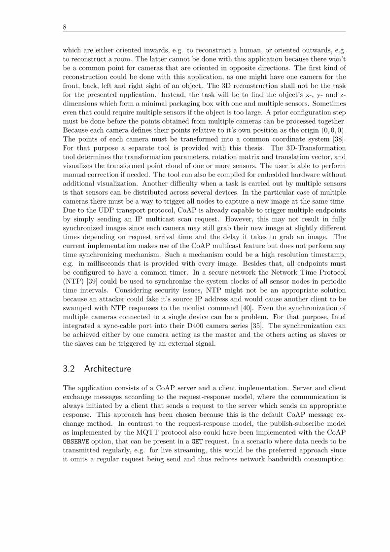
which are either oriented inwards, e.g. to reconstruct a human, or oriented outwards, e.g.to reconstruct a room. The latter cannot be done with this application because there won’tbe a common point for cameras that are oriented in opposite directions. The first kind ofreconstruction could be done with this application, as one might have one camera for thefront, back, left and right sight of an object. The 3D reconstruction shall not be the taskfor the presented application. Instead, the task will be to find the object’s x-, y- and z-dimensions which form a minimal packaging box with one and multiple sensors. Sometimeseven that could require multiple sensors if the object is too large. A prior configuration stepmust be done before the points obtained from multiple cameras can be processed together.Because each camera defines their points relative to it’s own position as the origin (0, 0, 0).The points of each camera must be transformed into a common coordinate system [38].For that purpose a separate tool is provided with this thesis. The 3D-Transformationtool determines the transformation parameters, rotation matrix and translation vector, andvisualizes the transformed point cloud of one or more sensors. The user is able to performmanual correction if needed. The tool can also be compiled for embedded hardware withoutadditional visualization. Another difficulty when a task is carried out by multiple sensorsis that sensors can be distributed across several devices. In the particular case of multiplecameras there must be a way to trigger all nodes to capture a new image at the same time.Due to the UDP transport protocol, CoAP is already capable to trigger multiple endpointsby simply sending an IP multicast scan request. However, this may not result in fullysynchronized images since each camera may still grab their new image at slightly differenttimes depending on request arrival time and the delay it takes to grab an image. Thecurrent implementation makes use of the CoAP multicast feature but does not perform anytime synchronizing mechanism. Such a mechanism could be a high resolution timestamp,e.g. in milliseconds that is provided with every image. Besides that, all endpoints mustbe configured to have a common timer. In a secure network the Network Time Protocol(NTP) [39] could be used to synchronize the system clocks of all sensor nodes in periodictime intervals. Considering security issues, NTP might not be an appropriate solutionbecause an attacker could fake it’s source IP address and would cause another client to beswamped with NTP responses to the monlist command [40]. Even the synchronization ofmultiple cameras connected to a single device can be a problem. For that purpose, Intelintegrated a sync-cable port into their D400 camera series [35]. The synchronization canbe achieved either by one camera acting as the master and the others acting as slaves orthe slaves can be triggered by an external signal.
3.2 Architecture
The application consists of a CoAP server and a client implementation. Server and clientexchange messages according to the request-response model, where the communication isalways initiated by a client that sends a request to the server which sends an appropriateresponse. This approach has been chosen because this is the default CoAP message ex-change method. In contrast to the request-response model, the publish-subscribe modelas implemented by the MQTT protocol also could have been implemented with the CoAPOBSERVE option, that can be present in a GET request. In a scenario where data needs to betransmitted regularly, e.g. for live streaming, this would be the preferred approach sinceit omits a regular request being send and thus reduces network bandwidth consumption.
9
/color
/pointcloud
/color-settings
/depth-settings
/application-config
/3d-transformation
/serial number 1 - n
/cams
/color
/pointcloud
/color-settings
/depth-settings
/application-config
/3d-transformation
/advanced-config
/advanced-config
/depth
/depth
/pointclouds
Figure 3.1: Application resource tree
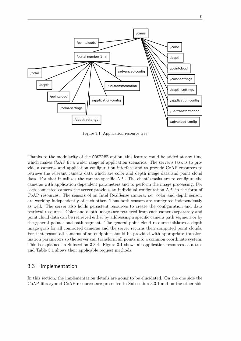
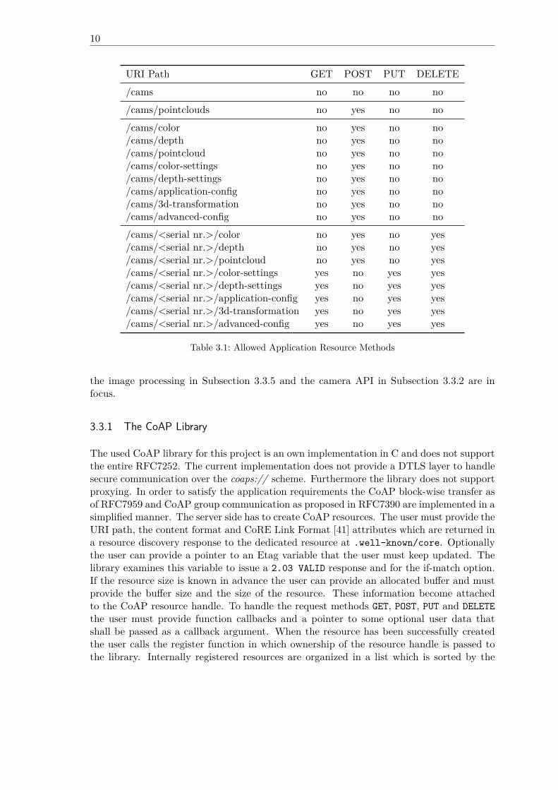
Thanks to the modularity of the OBSERVE option, this feature could be added at any timewhich makes CoAP fit a wider range of application scenarios. The server’s task is to pro-vide a camera- and application configuration interface and to provide CoAP resources toretrieve the relevant camera data which are color and depth image data and point clouddata. For that it utilizes the camera specific API. The client’s tasks are to configure thecameras with application dependent parameters and to perform the image processing. Foreach connected camera the server provides an individual configuration API in the form ofCoAP resources. The sensors of an Intel RealSense camera, i.e. color and depth sensor,are working independently of each other. Thus both sensors are configured independentlyas well. The server also holds persistent resources to create the configuration and dataretrieval resources. Color and depth images are retrieved from each camera separately andpoint cloud data can be retrieved either by addressing a specific camera path segment or bythe general point cloud path segment. The general point cloud resource initiates a depthimage grab for all connected cameras and the server returns their computed point clouds.For that reason all cameras of an endpoint should be provided with appropriate transfor-mation parameters so the server can transform all points into a common coordinate system.This is explained in Subsection 3.3.4. Figure 3.1 shows all application resources as a treeand Table 3.1 shows their applicable request methods.
3.3 Implementation
In this section, the implementation details are going to be elucidated. On the one side theCoAP library and CoAP resources are presented in Subsection 3.3.1 and on the other side
10
URI Path GET POST PUT DELETE/cams no no no no/cams/pointclouds no yes no no/cams/color no yes no no/cams/depth no yes no no/cams/pointcloud no yes no no/cams/color-settings no yes no no/cams/depth-settings no yes no no/cams/application-config no yes no no/cams/3d-transformation no yes no no/cams/advanced-config no yes no no/cams/<serial nr.>/color no yes no yes/cams/<serial nr.>/depth no yes no yes/cams/<serial nr.>/pointcloud no yes no yes/cams/<serial nr.>/color-settings yes no yes yes/cams/<serial nr.>/depth-settings yes no yes yes/cams/<serial nr.>/application-config yes no yes yes/cams/<serial nr.>/3d-transformation yes no yes yes/cams/<serial nr.>/advanced-config yes no yes yes
Table 3.1: Allowed Application Resource Methods
the image processing in Subsection 3.3.5 and the camera API in Subsection 3.3.2 are infocus.
3.3.1 The CoAP Library
The used CoAP library for this project is an own implementation in C and does not supportthe entire RFC7252. The current implementation does not provide a DTLS layer to handlesecure communication over the coaps:// scheme. Furthermore the library does not supportproxying. In order to satisfy the application requirements the CoAP block-wise transfer asof RFC7959 and CoAP group communication as proposed in RFC7390 are implemented in asimplified manner. The server side has to create CoAP resources. The user must provide theURI path, the content format and CoRE Link Format [41] attributes which are returned ina resource discovery response to the dedicated resource at .well-known/core. Optionallythe user can provide a pointer to an Etag variable that the user must keep updated. Thelibrary examines this variable to issue a 2.03 VALID response and for the if-match option.If the resource size is known in advance the user can provide an allocated buffer and mustprovide the buffer size and the size of the resource. These information become attachedto the CoAP resource handle. To handle the request methods GET, POST, PUT and DELETEthe user must provide function callbacks and a pointer to some optional user data thatshall be passed as a callback argument. When the resource has been successfully createdthe user calls the register function in which ownership of the resource handle is passed tothe library. Internally registered resources are organized in a list which is sorted by the
11
resource URI path. When a client sends a request that matches a registered resource theappropriate method callback is called with a general library handle argument which is calledcoap_interaction, the received CoAP message, a convenient struct that holds pointers toall present request options and the user created resource handle along with the genericuser data. Within the method callback the user should send the response according to theCoAP request/response semantics. If the user decides to respond to a confirmable messagein a separate response he or she must send an empty acknowledgement and any time laterhe or she can send the response. For example the user could use a thread that waitsfor the resource to become ready and as soon as that becomes true, the server sends theresponse. The client side must first create a coap_interaction handle to send a request.To that handle the user can attach a response callback together with some general user datawhich shall be passed as a callback argument. The response callback also receives a structholding pointers to present options in the response, the original request CoAP messageand the response CoAP message. Within the response callback the client should copy theresponse payload to an appropriate location. Most importantly, the response callback iswhere the client sends the next payload block in case of a present BLOCK1 option in a2.31 CONTINUE response or requests the next payload block to be send in case of a presentBLOCK2 option in a 2.05 CONTENT response. The coap_interaction structure is thegeneral library handle. In the sense of CoAP this handle represents the lifetime of a CoAPtoken that belongs to a CoAP remote node. Internally the interactions are stored in ahash table to achieve short response times. Not visible to the user, any coap_interactionhas it’s next timeout attached. The timeouts are organized in a future event list which isinternally programmed as a heap data structure. The CoAP library provides GET, POST, PUTand DELETE resource handlers for the coap-group resources described in RFC7390 [13]. InRFC7390 the application/coap-group+json content format is proposed. The JavaScriptObject Notation (JSON) content-format makes the CoAP library depend on a JSON librarythat has been chosen to be the cJSON library [42].
3.3.2 The Camera
The Intel D400 camera series [28] is the latest generation of Intel’s RealSense depth andcolor sensors that have been released in January 2018. Since November 2018, the D435i hasbeen released. It integrates an Inertial Measurement Unit (IMU) into the D435 camera tomake the camera capable of estimating it’s own pose which makes it well suited for roboticsand tracking applications. The cameras must be run over USB 3.0 to fully exploit theircapabilities, i.e. to enable all camera formats and resolutions. For this thesis two IntelRealSense D415 cameras have been tested. They are the cheapest model. The Intel D415is best suited for 3D scan applications [31] because it has a smaller field of view than theD435 and D435i. It delivers the best depth results when running at a resolution of 1280x720pixels [32]. Thus the same number of pixels covers a smaller area of the scene. Unlike theD435 and the D435i, the D415 has a rolling shutter rather than a global shutter. A rollingshutter does not work well for tracking applications where moving objects must be capturedbecause the image exposure is done line or column wise and not all pixels at once. Thusdistortions are the consequence.Each D400 camera can be interfaced with the librealsense library [43] from Intel. Natively,the library is programmed in C++ but the developers provide various wrappers, for example
12
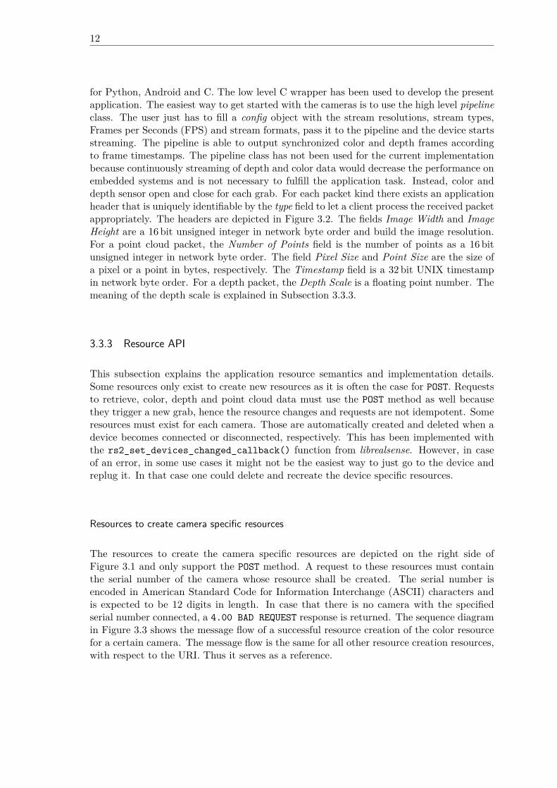
for Python, Android and C. The low level C wrapper has been used to develop the presentapplication. The easiest way to get started with the cameras is to use the high level pipelineclass. The user just has to fill a config object with the stream resolutions, stream types,Frames per Seconds (FPS) and stream formats, pass it to the pipeline and the device startsstreaming. The pipeline is able to output synchronized color and depth frames accordingto frame timestamps. The pipeline class has not been used for the current implementationbecause continuously streaming of depth and color data would decrease the performance onembedded systems and is not necessary to fulfill the application task. Instead, color anddepth sensor open and close for each grab. For each packet kind there exists an applicationheader that is uniquely identifiable by the type field to let a client process the received packetappropriately. The headers are depicted in Figure 3.2. The fields Image Width and ImageHeight are a 16 bit unsigned integer in network byte order and build the image resolution.For a point cloud packet, the Number of Points field is the number of points as a 16 bitunsigned integer in network byte order. The field Pixel Size and Point Size are the size ofa pixel or a point in bytes, respectively. The Timestamp field is a 32 bit UNIX timestampin network byte order. For a depth packet, the Depth Scale is a floating point number. Themeaning of the depth scale is explained in Subsection 3.3.3.
3.3.3 Resource API
This subsection explains the application resource semantics and implementation details.Some resources only exist to create new resources as it is often the case for POST. Requeststo retrieve, color, depth and point cloud data must use the POST method as well becausethey trigger a new grab, hence the resource changes and requests are not idempotent. Someresources must exist for each camera. Those are automatically created and deleted when adevice becomes connected or disconnected, respectively. This has been implemented withthe rs2_set_devices_changed_callback() function from librealsense. However, in caseof an error, in some use cases it might not be the easiest way to just go to the device andreplug it. In that case one could delete and recreate the device specific resources.
Resources to create camera specific resources
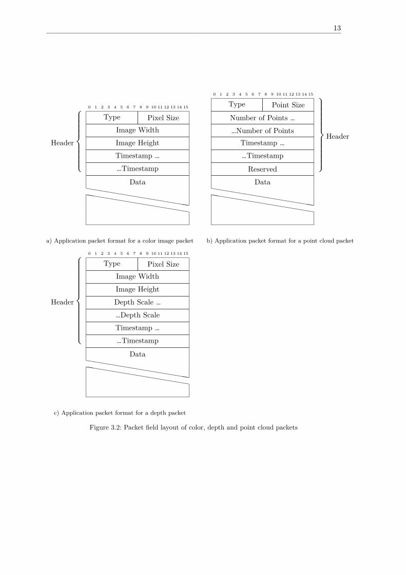
The resources to create the camera specific resources are depicted on the right side ofFigure 3.1 and only support the POST method. A request to these resources must containthe serial number of the camera whose resource shall be created. The serial number isencoded in American Standard Code for Information Interchange (ASCII) characters andis expected to be 12 digits in length. In case that there is no camera with the specifiedserial number connected, a 4.00 BAD REQUEST response is returned. The sequence diagramin Figure 3.3 shows the message flow of a successful resource creation of the color resourcefor a certain camera. The message flow is the same for all other resource creation resources,with respect to the URI. Thus it serves as a reference.
13
0 1 2 3 4 5 6 7 8 9 10 11 12 13 14 15
Type Pixel SizeImage WidthImage HeightTimestamp ……Timestamp
Header
⎧{{{{⎨{{{{⎩
Datahhhhhhhhhhhhhhhh
hhhhhhhhhhhhhhhh
a) Application packet format for a color image packet
0 1 2 3 4 5 6 7 8 9 10 11 12 13 14 15
Type Point SizeNumber of Points ……Number of Points
Timestamp ……Timestamp
Reserved
⎫}}}}}⎬}}}}}⎭
Header
Datahhhhhhhhhhhhhhhh
hhhhhhhhhhhhhhhh
b) Application packet format for a point cloud packet
0 1 2 3 4 5 6 7 8 9 10 11 12 13 14 15
Type Pixel SizeImage WidthImage HeightDepth Scale ……Depth ScaleTimestamp ……Timestamp
Header
⎧{{{{{{⎨{{{{{{⎩
Datahhhhhhhhhhhhhhhh
hhhhhhhhhhhhhhhh
c) Application packet format for a depth packet
Figure 3.2: Packet field layout of color, depth and point cloud packets
14
Client ServerPOST:/cams/color
Payload: <serial nr.>
2.01 CREATED
Figure 3.3: CoAP message flow of a successful resource creation of the color resource for a certaincamera
Resource: /cams/pointclouds
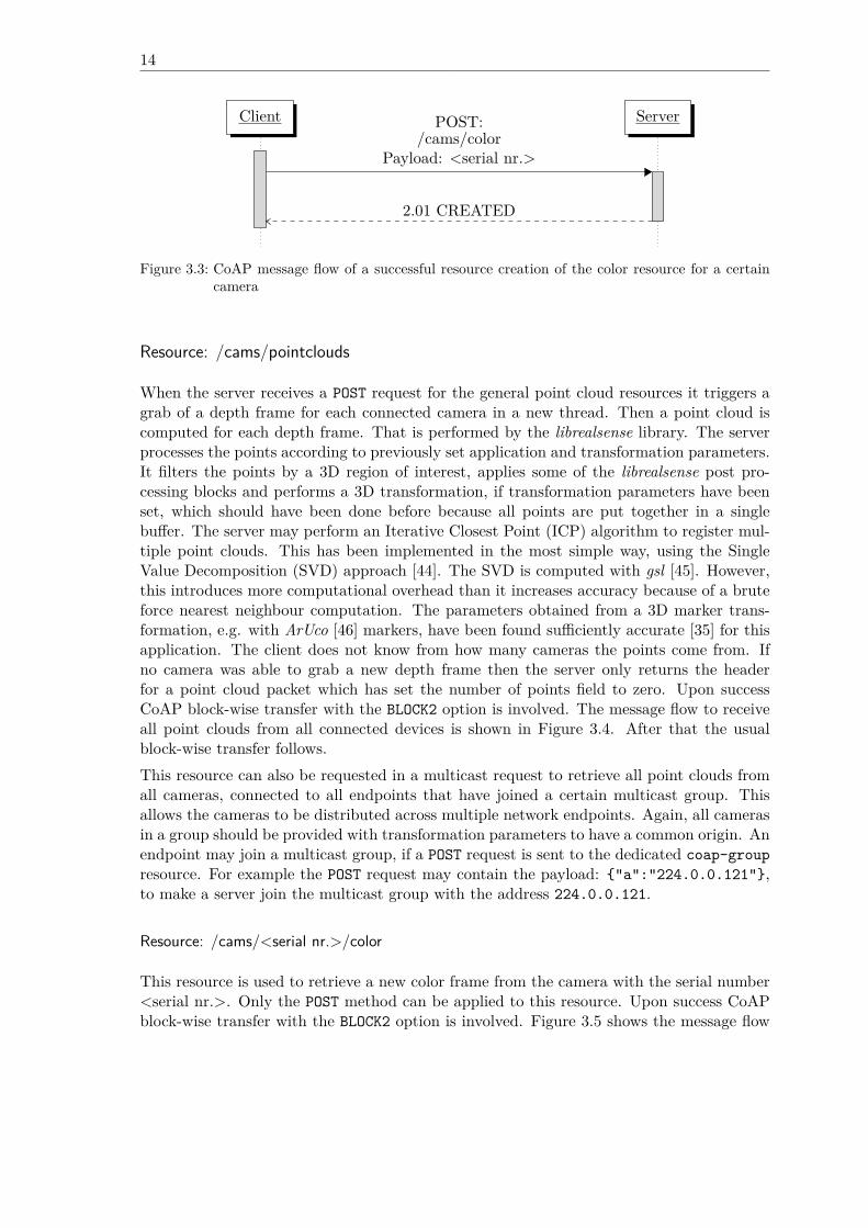
When the server receives a POST request for the general point cloud resources it triggers agrab of a depth frame for each connected camera in a new thread. Then a point cloud iscomputed for each depth frame. That is performed by the librealsense library. The serverprocesses the points according to previously set application and transformation parameters.It filters the points by a 3D region of interest, applies some of the librealsense post pro-cessing blocks and performs a 3D transformation, if transformation parameters have beenset, which should have been done before because all points are put together in a singlebuffer. The server may perform an Iterative Closest Point (ICP) algorithm to register mul-tiple point clouds. This has been implemented in the most simple way, using the SingleValue Decomposition (SVD) approach [44]. The SVD is computed with gsl [45]. However,this introduces more computational overhead than it increases accuracy because of a bruteforce nearest neighbour computation. The parameters obtained from a 3D marker trans-formation, e.g. with ArUco [46] markers, have been found sufficiently accurate [35] for thisapplication. The client does not know from how many cameras the points come from. Ifno camera was able to grab a new depth frame then the server only returns the headerfor a point cloud packet which has set the number of points field to zero. Upon successCoAP block-wise transfer with the BLOCK2 option is involved. The message flow to receiveall point clouds from all connected devices is shown in Figure 3.4. After that the usualblock-wise transfer follows.This resource can also be requested in a multicast request to retrieve all point clouds fromall cameras, connected to all endpoints that have joined a certain multicast group. Thisallows the cameras to be distributed across multiple network endpoints. Again, all camerasin a group should be provided with transformation parameters to have a common origin. Anendpoint may join a multicast group, if a POST request is sent to the dedicated coap-groupresource. For example the POST request may contain the payload: {"a":"224.0.0.121"},to make a server join the multicast group with the address 224.0.0.121.
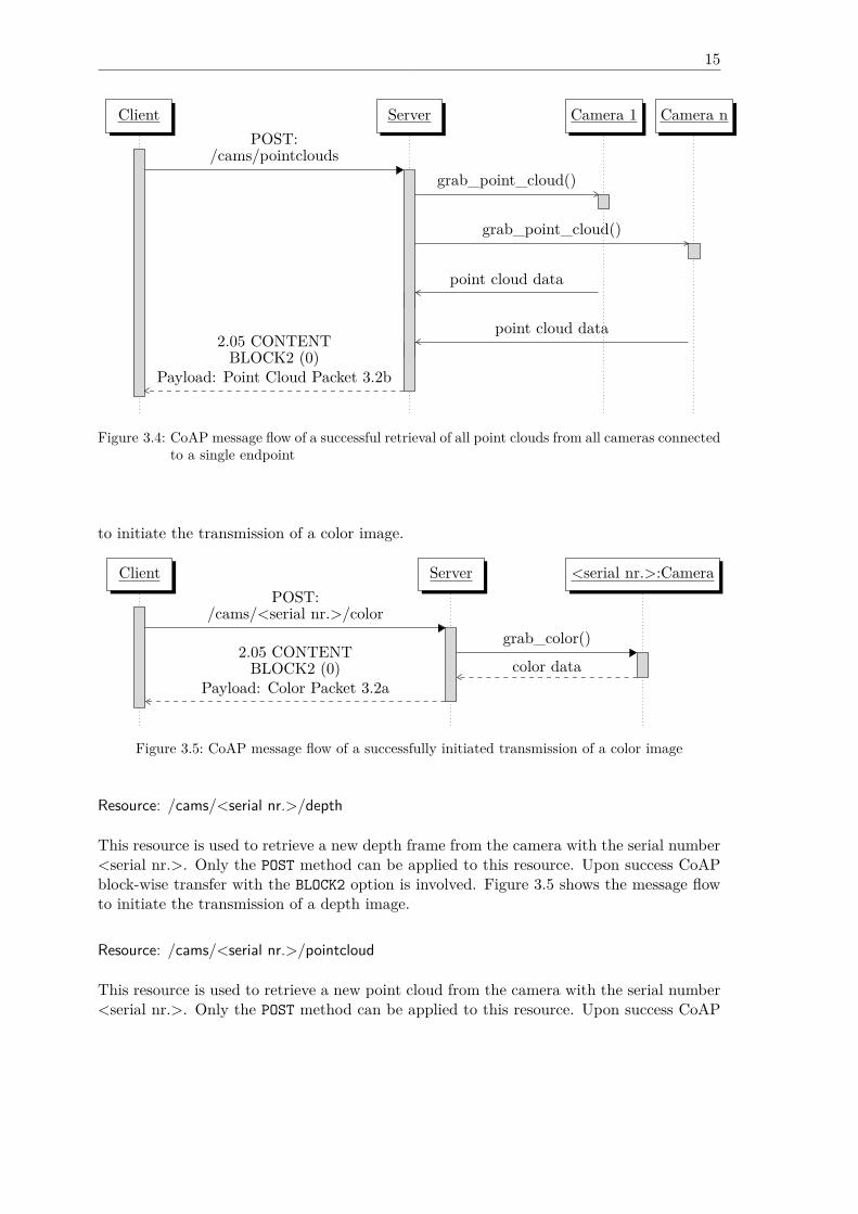
Resource: /cams/<serial nr.>/color
This resource is used to retrieve a new color frame from the camera with the serial number<serial nr.>. Only the POST method can be applied to this resource. Upon success CoAPblock-wise transfer with the BLOCK2 option is involved. Figure 3.5 shows the message flow
15
Client Server Camera 1 Camera nPOST:
/cams/pointcloudsgrab_point_cloud()
grab_point_cloud()
point cloud data
point cloud data2.05 CONTENT
BLOCK2 (0)Payload: Point Cloud Packet 3.2b
Figure 3.4: CoAP message flow of a successful retrieval of all point clouds from all cameras connectedto a single endpoint
to initiate the transmission of a color image.
Client Server <serial nr.>:CameraPOST:
/cams/<serial nr.>/colorgrab_color()
color data2.05 CONTENT
BLOCK2 (0)Payload: Color Packet 3.2a
Figure 3.5: CoAP message flow of a successfully initiated transmission of a color image
Resource: /cams/<serial nr.>/depth
This resource is used to retrieve a new depth frame from the camera with the serial number<serial nr.>. Only the POST method can be applied to this resource. Upon success CoAPblock-wise transfer with the BLOCK2 option is involved. Figure 3.5 shows the message flowto initiate the transmission of a depth image.
Resource: /cams/<serial nr.>/pointcloud
This resource is used to retrieve a new point cloud from the camera with the serial number<serial nr.>. Only the POST method can be applied to this resource. Upon success CoAP
16
Client Server <serial nr.>:CameraPOST:
/cams/<serial nr.>/depthgrab_depth()
depth data2.05 CONTENT
BLOCK2 (0)Payload: Depth Packet 3.2c
Figure 3.6: CoAP message flow of a successfully initiated transmission of a depth image
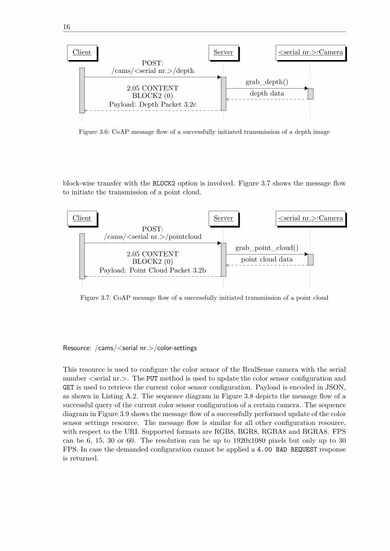
block-wise transfer with the BLOCK2 option is involved. Figure 3.7 shows the message flowto initiate the transmission of a point cloud.
Client Server <serial nr.>:CameraPOST:
/cams/<serial nr.>/pointcloudgrab_point_cloud()
point cloud data2.05 CONTENT
BLOCK2 (0)Payload: Point Cloud Packet 3.2b
Figure 3.7: CoAP message flow of a successfully initiated transmission of a point cloud
Resource: /cams/<serial nr.>/color-settings
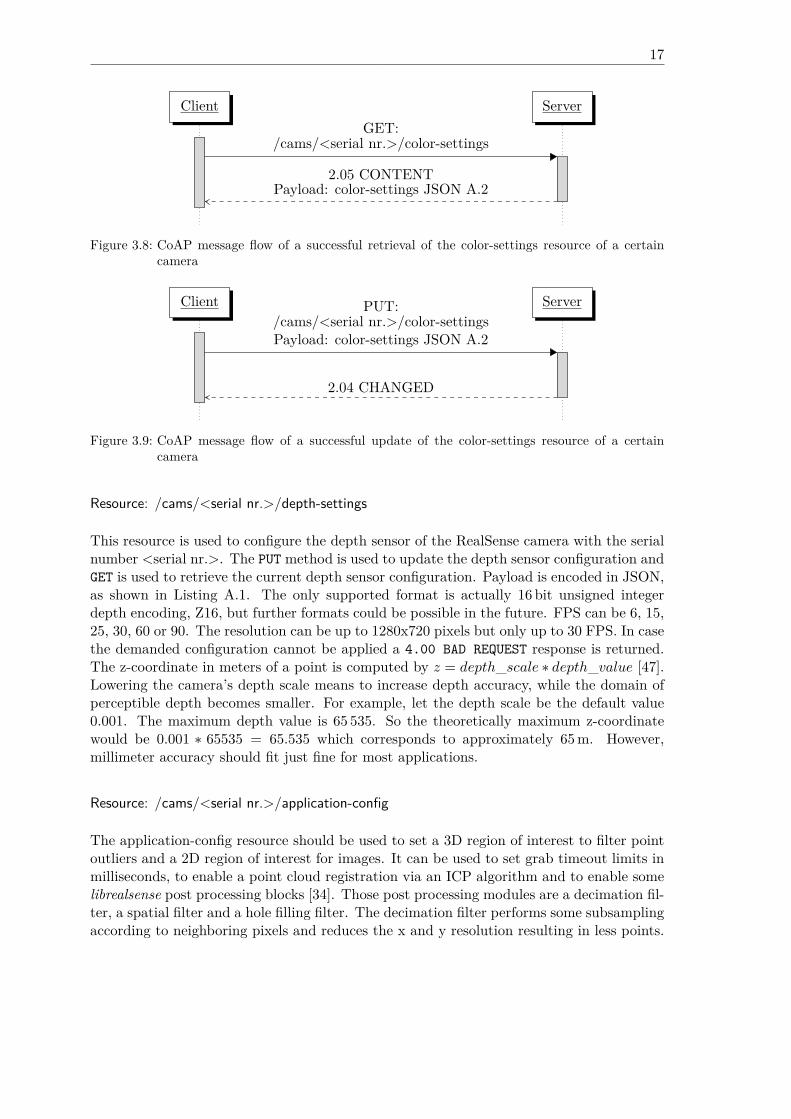
This resource is used to configure the color sensor of the RealSense camera with the serialnumber <serial nr.>. The PUT method is used to update the color sensor configuration andGET is used to retrieve the current color sensor configuration. Payload is encoded in JSON,as shown in Listing A.2. The sequence diagram in Figure 3.8 depicts the message flow of asuccessful query of the current color sensor configuration of a certain camera. The sequencediagram in Figure 3.9 shows the message flow of a successfully performed update of the colorsensor settings resource. The message flow is similar for all other configuration resource,with respect to the URI. Supported formats are RGB8, BGR8, RGBA8 and BGRA8. FPScan be 6, 15, 30 or 60. The resolution can be up to 1920x1080 pixels but only up to 30FPS. In case the demanded configuration cannot be applied a 4.00 BAD REQUEST responseis returned.
17
Client ServerGET:
/cams/<serial nr.>/color-settings
2.05 CONTENTPayload: color-settings JSON A.2
Figure 3.8: CoAP message flow of a successful retrieval of the color-settings resource of a certaincamera
Client ServerPUT:/cams/<serial nr.>/color-settingsPayload: color-settings JSON A.2
2.04 CHANGED
Figure 3.9: CoAP message flow of a successful update of the color-settings resource of a certaincamera
Resource: /cams/<serial nr.>/depth-settings
This resource is used to configure the depth sensor of the RealSense camera with the serialnumber <serial nr.>. The PUT method is used to update the depth sensor configuration andGET is used to retrieve the current depth sensor configuration. Payload is encoded in JSON,as shown in Listing A.1. The only supported format is actually 16 bit unsigned integerdepth encoding, Z16, but further formats could be possible in the future. FPS can be 6, 15,25, 30, 60 or 90. The resolution can be up to 1280x720 pixels but only up to 30 FPS. In casethe demanded configuration cannot be applied a 4.00 BAD REQUEST response is returned.The z-coordinate in meters of a point is computed by 𝑧 = 𝑑𝑒𝑝𝑡ℎ_𝑠𝑐𝑎𝑙𝑒 ∗ 𝑑𝑒𝑝𝑡ℎ_𝑣𝑎𝑙𝑢𝑒 [47].Lowering the camera’s depth scale means to increase depth accuracy, while the domain ofperceptible depth becomes smaller. For example, let the depth scale be the default value0.001. The maximum depth value is 65 535. So the theoretically maximum z-coordinatewould be 0.001 ∗ 65535 = 65.535 which corresponds to approximately 65 m. However,millimeter accuracy should fit just fine for most applications.
Resource: /cams/<serial nr.>/application-config
The application-config resource should be used to set a 3D region of interest to filter pointoutliers and a 2D region of interest for images. It can be used to set grab timeout limits inmilliseconds, to enable a point cloud registration via an ICP algorithm and to enable somelibrealsense post processing blocks [34]. Those post processing modules are a decimation fil-ter, a spatial filter and a hole filling filter. The decimation filter performs some subsamplingaccording to neighboring pixels and reduces the x and y resolution resulting in less points.
18
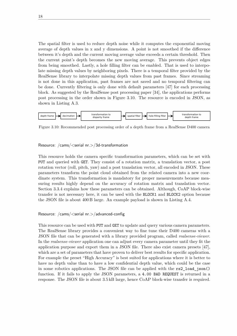
The spatial filter is used to reduce depth noise while it computes the exponential movingaverage of depth values in x and y dimensions. A point is not smoothed if the differencebetween it’s depth and the current moving average value exceeds a certain threshold. Thenthe current point’s depth becomes the new moving average. This prevents object edgesfrom being smoothed. Lastly, a hole filling filter can be enabled. That is used to interpo-late missing depth values by neighboring pixels. There is a temporal filter provided by theRealSense library to interpolate missing depth values from past frames. Since streamingis not done in this application, past frames are not saved and no temporal filtering canbe done. Currently filtering is only done with default parameters [47] for each processingblock. As suggested by the RealSense post processing paper [34], the applications performspost processing in the order shown in Figure 3.10. The resource is encoded in JSON, asshown in Listing A.3.
decimationtransformation todisparity frame
spatial filter hole-filling filtertransformation to
depth framedepth frame
Figure 3.10: Recommended post processing order of a depth frame from a RealSense D400 camera
Resource: /cams/<serial nr.>/3d-transformation
This resource holds the camera specific transformation parameters, which can be set withPUT and queried with GET. They consist of a rotation matrix, a translation vector, a postrotation vector (roll, pitch, yaw) and a post translation vector, all encoded in JSON. Theseparameters transform the point cloud obtained from the related camera into a new coor-dinate system. This transformation is mandatory for proper measurements because mea-suring results highly depend on the accuracy of rotation matrix and translation vector.Section 3.3.4 explains how these parameters can be obtained. Although, CoAP block-wisetransfer is not necessary here, it can be used with the BLOCK1 and BLOCK2 option becausethe JSON file is about 400 B large. An example payload is shown in Listing A.4.
Resource: /cams/<serial nr.>/advanced-config
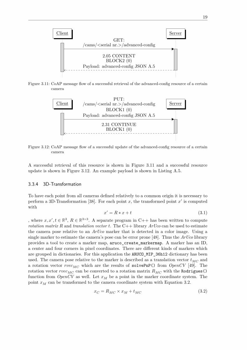
This resource can be used with PUT and GET to update and query various camera parameters.The RealSense library provides a convenient way to fine tune their D400 cameras with aJSON file that can be generated with a library provided program, called realsense-viewer.In the realsense-viewer application one can adjust every camera parameter until they fit theapplication purpose and export them in a JSON file. There also exist camera presets [47],which are a set of parameters that have proven to deliver best results for specific application.For example the preset “High Accuracy” is best suited for applications where it is better tohave no depth value than to have a low confidential depth value, which could be the casein some robotics applications. The JSON file can be applied with the rs2_load_json()function. If it fails to apply the JSON parameters, a 4.00 BAD REQUEST is returned in aresponse. The JSON file is about 3.5 kB large, hence CoAP block-wise transfer is required.
19
Client ServerGET:
/cams/<serial nr.>/advanced-config
2.05 CONTENTBLOCK2 (0)
Payload: advanced-config JSON A.5
Figure 3.11: CoAP message flow of a successful retrieval of the advanced-config resource of a certaincamera
Client ServerPUT:
/cams/<serial nr.>/advanced-configBLOCK1 (0)
Payload: advanced-config JSON A.5
2.31 CONTINUEBLOCK1 (0)
Figure 3.12: CoAP message flow of a successful update of the advanced-config resource of a certaincamera
A successful retrieval of this resource is shown in Figure 3.11 and a successful resourceupdate is shown in Figure 3.12. An example payload is shown in Listing A.5.
3.3.4 3D-Transformation
To have each point from all cameras defined relatively to a common origin it is necessary toperform a 3D-Transformation [38]. For each point 𝑥, the transformed point 𝑥′ is computedwith
𝑥′ = 𝑅 ∗ 𝑥 + 𝑡 (3.1), where 𝑥, 𝑥′, 𝑡 ∈ ℝ3, 𝑅 ∈ ℝ3×3. A separate program in C++ has been written to computerotation matrix 𝑅 and translation vector 𝑡. The C++ library ArUco can be used to estimatethe camera pose relative to an ArUco marker that is detected in a color image. Using asingle marker to estimate the camera’s pose can be error prone [48]. Thus the ArUco libraryprovides a tool to create a marker map, aruco_create_markermap. A marker has an ID,a center and four corners in pixel coordinates. There are different kinds of markers whichare grouped in dictionaries. For this application the ARUCO_MIP_36h12 dictionary has beenused. The camera pose relative to the marker is described as a translation vector 𝑡𝑀𝐶 anda rotation vector 𝑟𝑣𝑒𝑐𝑀𝐶 which are the results of solvePnP() from OpenCV [49]. Therotation vector 𝑟𝑣𝑒𝑐𝑀𝐶 can be converted to a rotation matrix 𝑅𝑀𝐶 with the Rodrigues()function from OpenCV as well. Let 𝑥𝑀 be a point in the marker coordinate system. Thepoint 𝑥𝑀 can be transformed to the camera coordinate system with Equation 3.2.
𝑥𝐶 = 𝑅𝑀𝐶 × 𝑥𝑀 + 𝑡𝑀𝐶 (3.2)
20
To get the opposite direction from the camera coordinate system to the marker coordinatesystem, Equation 3.2 must be converted to Equation 3.6.
𝑥𝐶 = 𝑅𝑀𝐶 × 𝑥𝑀 + 𝑡𝑀𝐶 (3.3)𝑥𝐶 − 𝑡𝑀𝐶 = 𝑅𝑀𝐶 × 𝑥𝑀 (3.4)
𝑅−1𝑀𝐶 × (𝑥𝐶 − 𝑡𝑀𝐶) = 𝑥𝑀 (3.5)
𝑥𝑀 = 𝑅−1𝑀𝐶 × 𝑥𝐶 − 𝑅−1
𝑀𝐶 ∗ 𝑡𝑀𝐶 (3.6)
The resulting rotation matrix 𝑅𝐶𝑀 to transform a point from the camera coordinate sys-tem to the marker coordinate system is 𝑅−1
𝑀𝐶 and the resulting translation vector 𝑡𝐶𝑀 totransform a point from the camera coordinate system to the marker coordinate system is−𝑅−1
𝑀𝐶 ∗ 𝑡𝑀𝐶. Before 𝑟𝑣𝑒𝑐𝑀𝐶 and 𝑡𝑣𝑒𝑐𝑀𝐶 can be computed ArUco must be provided withthe camera Intrinsic Parameters of the color sensor. That are a camera matrix 𝐶 3.3.4 anda tupel 𝑑 of five distortion values. Both can be obtained from a camera calibration.
𝐶 = ⎛⎜⎝
𝑓𝑥 0 𝑐𝑥0 𝑓𝑦 𝑐𝑦0 0 1
⎞⎟⎠
The parameter 𝑓𝑥 is the Focal Length in multiples of pixel x-length, 𝑓𝑦 is the Focal Lengthin multiples of pixel y-length, 𝑐𝑥 is the x pixel coordinate of the Principal Point and 𝑐𝑦is the y pixel coordinate of the Principal Point. Intrinsic Parameters are stored on thecamera and have been estimated when the camera has been factory calibrated [36]. Theyare not the same for the same camera model, thus each camera needs an individual cali-bration. The quality of the calibration parameters varies from camera to camera. Whilethe camera with serial number 809512060141 does not have very accurate parameters, thepoints from the camera with serial number 840412060746 transform very well with fac-tory determined parameters. A recalibration of a camera is possible but not as accurateas can be done with professional equipment. Even though Intel provides a paper and acalibration framework [36], self-determined parameters from 100 images resulted in worseresults. The RealSense library provides an interface to query the intrinsic camera parame-ters, rs2_get_video_stream_intrinsics(). The distortion coefficients returned by thatfunction are always zero. So it can be assumed that frames automatically become rectifiedby the library. However, there must be distortion. The real distortion coefficients for theleft and right imagers can be queried with an external tool that is mentioned in the cameracalibration white paper from Intel. But distortion coefficients for the RGB sensor are notprovided by Intel. To read the camera calibration from the device the CustomRW toolfrom Intel can be used with CustomRW -sn <serial nr.> -r -f <outfile.xml>.The transformation tool takes as arguments: the configuration file for the generated markermap, the actual marker size in meters e.g. printed on a sheet of paper, the serial numberof the camera, the file that contains the Intrinsic Parameters, width resolution, heightresolution, a number of threads that shall be used to transform all points and an outputfile. The librealsense pipeline API is used to start streaming color and depth frames from aRealSense camera and ArUco tries to detect the configured marker map in the color image.When the marker map could be detected successfully, transformation parameters 𝑅𝐶𝑀 and𝑡𝐶𝑀 were computed. These parameters hold for the transformation from the color sensorto the marker map center, but each point in a point cloud from a D400 RealSense camera
21
is defined relative to the left imager, so the extrinsic transformation parameters from theleft imager to the color sensor must be applied as well. The Extrinsic Parameters from theimagers to the color sensor and vice versa have also been stored on the camera at the time offactory calibration and can be queried with the rs2_register_extrinsics() function. Let𝑅1 be the rotation matrix from the left imager to the color sensor and 𝑡1 the transformationvector from the left imager to the color sensor. Let 𝑅2 be the rotation matrix from thecolor sensor to the marker map and 𝑡2 the transformation vector from the color sensor tothe marker map. A point 𝑥 in the camera coordinate system is transformed to 𝑥′ in themarker coordinate system, as shown in Equation 3.8.
𝑥′ = 𝑅2 × (𝑅1 × 𝑥 + 𝑡1) + 𝑡2 (3.7)= 𝑅2 × 𝑅1 × 𝑥 + 𝑅2 × 𝑡1 + 𝑡2 (3.8)
If the tool was compiled with make WITH_GRAPHICS=1 then the transformed points are visu-alized with OpenGL [50] and GLEW [51] and the user will be able to apply manual correc-tion, with respect to rotation, translation and scaling. Manual changes in rotation are storedas roll, pitch and yaw values in degrees, where roll is the rotation around the x-axis, pitch isthe rotation around the y-axis and yaw is the rotation around the z-axis, with respect to theobject coordinate system. The result should be that the world axis lie in the center of themarker map, with the z-axis perpendicular. Other library dependencies are GLFW [52] to cre-ate a window and to capture user input and glm [53] for matrix computations. For an embed-ded device the tool should not be compiled with extra graphical support. The tool producesan output file in JSON that lists ``rotation_matrix'' and ``translation_matrix'' asthe result of the computed transformation and ``post_rotation_matrix'' (roll, pitch, yaw) and ``post_translation_matrix'' as the result of the manual correction. A``scale_matrix'' and a ``post_scale_matrix'' are also contained in the file but notneeded for the application of this thesis. Figure 3.13 shows the transformation result.
3.3.5 Image Processing
In order to compute object dimensions, some image processing has to be done by the client.The client application depends on OpenCV [49] with a version prior to 4.0.0 because sincethe release of OpenCV 4.0.0 the compilation standard has been raised to C++ 11 and theC API has been dropped.It is assumed that all cameras are facing the ground and have been configured to use acommon coordinate system with the z-axis pointing upwards and is oriented perpendicularto the ground. The measuring area should be free of any other object that shall not bemeasured because only one object can be measured at a time. In advance a minimum z valuefor all points of interest should have been configured in the application-config resource fromSubsection 3.3.3 for all cameras because points that represent the ground should not betransmitted by the server. The only points of interest for the computation are those whichform the upper surface of the object within the measuring range. The object’s z dimensionis computed as the maximum observed z-value from the points that form the upper surface.To compute x and y dimensions only the x and y components of a point are considered. Fromthese 2D points the convex hull is computed with OpenCV’s cvConvexHull2() function.The resulting points are then used as input to OpenCV’s cvMinAreaRect2() function which
22
Figure 3.13: Aligned point clouds after 3D transformation
23
computes the minimum area rectangle that encloses all points. The rectangle’s width andheight are the x and y dimensions of the object below the sensors.
3.4 Experiments
This section is dedicated to the performance analysis of the presented application thatprovides color, depth and point cloud data from RealSense D400 cameras as CoAP resources.The experiments only cover the color and point cloud resource of a single camera but notthe depth image resource because the depth image is just a prestage of the point cloud.Experimental parameters are hardware, resolution and network overhead. Tests have beenexecuted on a desktop computer and on embedded hardware. Because performance stronglydepends on the CoAP library, libcoap has been used as a well known library reference. Asa test scenario, a client initiates the block-wise transfer of the requested resource 32 times,with the maximum block size of 1024 B [18]. After each transmission of a complete imageor point cloud, the client sleeps for one second. For each test case, transmission times andmoving average transmission times for each complete resource transmission are measured.The term “transmission time” is defined to be the elapsed time from request transmissionto the last successfully received response which completes the transmission of a resource.Hence, “transmission time” includes processing delay which includes the time it takes tograb an image. The average time from 32 grabs of a color image has been measured withca. 0.1 s, while the average time to grab a depth frame and to calculate the point cloudhas been measured with ca. 0.185 s. Server statistics, i.e. user CPU time, system CPUtime and maximum resident set size, are obtained with getrusage(). Some test cases havebeen repeated with valgrind --tool=callgrind --simulate-cache=yes to capture thenumber of executed instructions, instruction miss rate, data accesses and data access missrate. Table 3.2 lists the hardware that has been used. The application has been compiledwith clang -O3.
Name: Desktop Lenovo-Yoga L390 Odroid-Xu4OS: Ubuntu 18.04 Arch Linux Ubuntu 18.04Kernel: 4.15.0-48-generic 5.0.3-arch1-1-ARCH 4.14.111-158CPU: i5-4460 - 3.20GHz i5-8265U - 1.6GHz SAMSUNG Exynos 5422Cores: 4 8 8RAM: 8GB DDR3 8GB DDR3 2GB LPDDR3Network: 802.11n - 2.4GHz 802.11n - 2.4GHz Ethernet
Table 3.2: Hardware that has been used in all test cases
3.4.1 Test Case 1: (Color, 640x480, local)
In the first test case the camera has been configured to produce color frames at a resolutionof 640x480 pixels in BGR8 format. Server and client application both have been runningon the same desktop computer from Table 3.2. 640 × 480 × 3 B + 10 B header result in
24
921 610 B of CoAP response payload to be transferred 32 times. This test case has alsobeen repeated with Callgrind.
3.4.2 Test Case 2: (Color, 1280x720, local)
The second test case shows how the color image resolution affects the measured parameters.The camera has been configured to produce color frames at a resolution of 1280x720 pixelsin BGR8 format. Server and client application both have been running on the same desktopcomputer from Table 3.2. 1280 × 720 × 3 B + 10 B header result in 2 764 810 B of CoAPresponse payload to be transferred 32 times. Because the resolution in test case 2 is 2 timeshigher than in test case 1, the average response time is expected to be thrice as much as intest case 1. This test case has also been repeated with Callgrind.
Hypothesis 1 (H1): The average transmission time in test case 2 will be at most thriceas much as in test case 1.
Hypothesis 2 (H2): The number of instructions in test case 2 will be at most thrice ashigh as in test case 1.
Hypothesis 3 (H3): The maximum resident set size in test case 2 will be at most thriceas much as in test case 1.
3.4.3 Test Case 3: (libcoap, 2764810 Byte, local)
The same amount of data as in test case 2 has been transferred in this test case but libcoaphas been used as a CoAP library reference to illuminate the influence of the CoAP libraryand the CoAP block-wise transfer implementation. To make test case 3 comparable withtest case 2, server and client both have been running locally on the same machine as in testcase 2. For hypothesis, see test case 8 in Subsection 3.4.8.
3.4.4 Test Case 4: (Color, 1280x720, 1-Hop)
Test case 4 is a repetition of test case 2 but this time in a wireless network scenario. Theserver has been running on the desktop computer and the client has been running on theLenovo Yoga L390, both listed in Table 3.2.
Hypothesis 4 (H4): The average transmission time in test case 4 will be higher than theaverage transmission time in test case 2 and transmission times will have a greater variance.
Hypothesis 5 (H5): The maximum resident set size in test case 4 will be approximatelyas large as the maximum resident set size in test case 2.
3.4.5 Test Case 5: (Embedded, Color, 1280x720, 1-Hop)
Test case 5 is a repetition of test case 4, where the server has been running on an Odroid-Xu4 and the client has been running on the desktop computer. Test case 5 is not fullycomparable to test case 4 because the Odroid does not have a WiFi interface.
25
Hypothesis 6 (H6): The average transmission time in test case 5 will be higher than theaverage transmission time in test case 4.
Hypothesis 7 (H7): The maximum resident set size in test case 5 will be approximatelyas large as the maximum resident set size in test case 4.
3.4.6 Test Case 6: (Point Cloud, 640x480, local)
In the 6th test case the camera has been configured to produce point clouds from depthimages at a resolution of 640x480 pixels in Z16 format. Server and client application bothhave been running at the same desktop computer from Table 3.2. The observed numberof valid points has been approximately 286 000. 286 000 points × 12 B per point + 12 Bheader result in 3 432 012 B of response CoAP payload to be transferred 32 times. This testcase has also been repeated with Callgrind.
Hypothesis 8 (H8): The average transmission time in test case 6 will be greater than theaverage transmission time in test case 1.
Hypothesis 9 (H9): The maximum resident set size in test case 6 will be greater than themaximum resident set size in test case 1.
Hypothesis 10 (H10): The number of instructions in test case 6 will be higher than thenumber of instructions in test case 1.
3.4.7 Test Case 7: (Point Cloud, 1280x720, local)
Test case 7 shows how the depth image resolution affects the measured parameters. Thecamera has been configured to produce point clouds from depth frames at a resolution of1280x720 pixels in Z16 format. Server and client application both have been running onthe same desktop computer from Table 3.2. The observed number of valid points has beenapproximately 836 000. 836 000 points × 12 B per point + 12 B header result in 10 032 012 Bof CoAP response payload to be transferred 32 times. This test case has also been repeatedwith Callgrind.
Hypothesis 11 (H11): The average transmission time in test case 7 will be at most thriceas much as in test case 6.
Hypothesis 12 (H12): The number of instructions in test case 7 will be at most thriceas high as in test case 6.
Hypothesis 13 (H13): The maximum resident set size in test case 7 will be at most thriceas much as in test case 6.
3.4.8 Test Case 8: (libcoap, 10032012 Byte, local)
In test case 8 libcoap has again been used to serve as a CoAP library reference implemen-tation to transfer 10 032 012 B via block-wise transfer.
26
Hypothesis 14 (H14): libcoap will have similar transmission times to the custom CoAPlibrary.
Hypothesis 15 (H15): libcoap will need less memory than the custom CoAP library.
3.4.9 Test Case 9: (Point Cloud, 1280x720, 1-Hop)
In test case 9 a point cloud from a depth frame at a resolution of 1280x720 pixels in Z16format has been transmitted over 1 hop in a wireless network, 32 times. The server hasbeen the desktop PC and the client has been the Lenovo laptop from Table 3.2.
Hypothesis 16 (H16): The average transmission time in test case 9 will be higher thanthe average transmission time in test case 7 and transmission times will have a greatervariance.
Hypothesis 17 (H17): The maximum resident set size in test case 9 will be approximatelyas large as the maximum resident set size in test case 7.
3.4.10 Test Case 10: (Point Cloud, Decimation, 1280x720, 1-Hop)
The RealSense library provides a decimation filter to reduce the number of points in apoint cloud. This test has been accomplished to show the influence of post processing withrespect to the measured parameters.
Hypothesis 18 (H18): The average transmission time in test case 10 will be lower thanthe average transmission time in test case 9.
Hypothesis 19 (H19): The maximum resident set size in test case 10 will be approxi-mately the same as in test case 9.
3.4.11 Test Case 11: (Embedded, Point Cloud, Decimation, 1280x720, 1-Hop)
To complete all test cases, the 11th test case repeats test case 10 with the Odroid-Xu4 asa CoAP server and the desktop computer as a CoAP client.
Hypothesis 20 (H20): The average transmission time in test case 11 will be higher thanthe average transmission time in test case 10.
Hypothesis 21 (H21): The maximum resident set size in test case 11 will be approxi-mately the same as in test case 10.
CHAPTER 4
Thesis Outcome
In this chapter, the test cases from the previous chapter are evaluated. At the end of Sec-tion 4.1 there are evaluation charts in Subsection 4.1.12 that show each test case, comparedto each other, with respect to one measured parameter.
4.1 Evaluation
This section evaluates the described test cases from the previous section. There is a shorttable that summarizes rounded values of the minimum, maximum and average transmissiontime, standard deviation and the coefficient of variance for each test case. The transmissiontimes mark an upper bound because as described in Subsection 3.3.5, only the upper surfaceis needed to compute the object dimensions. It is up to the user to configure a 3D measuringrage with the resource shown in Subsection 3.3.3 to limit the number of points that actuallyneed to be transmitted. Measurements of the time spent in user space and kernel space areinaccurate. Instead, Callgrind is a better measure of program complexity.
4.1.1 Evaluation Test Case 1: (Color, 640x480, local)
Except for the first transmission which almost took 0.6 s, all local transmissions of a 640x480color image have been completed within 0.11 s and 0.14 s. The transmission times are ex-pectedly small and there is almost no variance. The rolling average transmission time tendsto decrease. For the last transmission the average was about 0.138 s. The maximum resi-dent set size after all transmissions was 138 624 kB. When the test has been repeated withCallgrind, 10 484 381 115 instruction- and 2 619 011 862 data references have been measured,where the I1 miss rate was 0.06%, D1 miss rate was 0.2% and LLD miss rate was 0.01%.The program has almost spent twice as much time in system space than in user space.
28
Min. [ns] Max. [ns] Avg. [ns] SD. [ns] Coefficient OfVariance
114 601 127 597 480 766 137 930 475 82 792 576 0.60
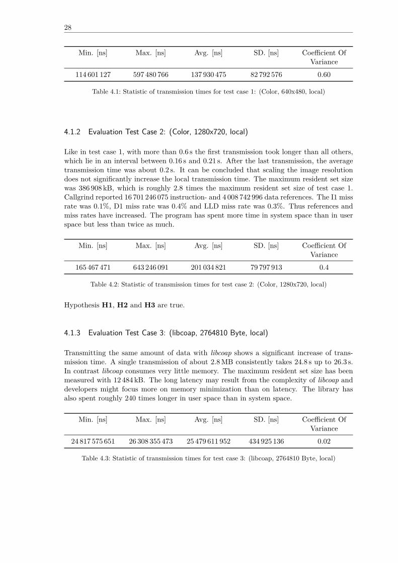
Table 4.1: Statistic of transmission times for test case 1: (Color, 640x480, local)
4.1.2 Evaluation Test Case 2: (Color, 1280x720, local)
Like in test case 1, with more than 0.6 s the first transmission took longer than all others,which lie in an interval between 0.16 s and 0.21 s. After the last transmission, the averagetransmission time was about 0.2 s. It can be concluded that scaling the image resolutiondoes not significantly increase the local transmission time. The maximum resident set sizewas 386 908 kB, which is roughly 2.8 times the maximum resident set size of test case 1.Callgrind reported 16 701 246 075 instruction- and 4 008 742 996 data references. The I1 missrate was 0.1%, D1 miss rate was 0.4% and LLD miss rate was 0.3%. Thus references andmiss rates have increased. The program has spent more time in system space than in userspace but less than twice as much.
Min. [ns] Max. [ns] Avg. [ns] SD. [ns] Coefficient OfVariance
165 467 471 643 246 091 201 034 821 79 797 913 0.4
Table 4.2: Statistic of transmission times for test case 2: (Color, 1280x720, local)
Hypothesis H1, H2 and H3 are true.
4.1.3 Evaluation Test Case 3: (libcoap, 2764810 Byte, local)
Transmitting the same amount of data with libcoap shows a significant increase of trans-mission time. A single transmission of about 2.8 MB consistently takes 24.8 s up to 26.3 s.In contrast libcoap consumes very little memory. The maximum resident set size has beenmeasured with 12 484 kB. The long latency may result from the complexity of libcoap anddevelopers might focus more on memory minimization than on latency. The library hasalso spent roughly 240 times longer in user space than in system space.
Min. [ns] Max. [ns] Avg. [ns] SD. [ns] Coefficient OfVariance
24 817 575 651 26 308 355 473 25 479 611 952 434 925 136 0.02
Table 4.3: Statistic of transmission times for test case 3: (libcoap, 2764810 Byte, local)
29
4.1.4 Evaluation Test Case 4: (Color, 1280x720, 1-Hop)
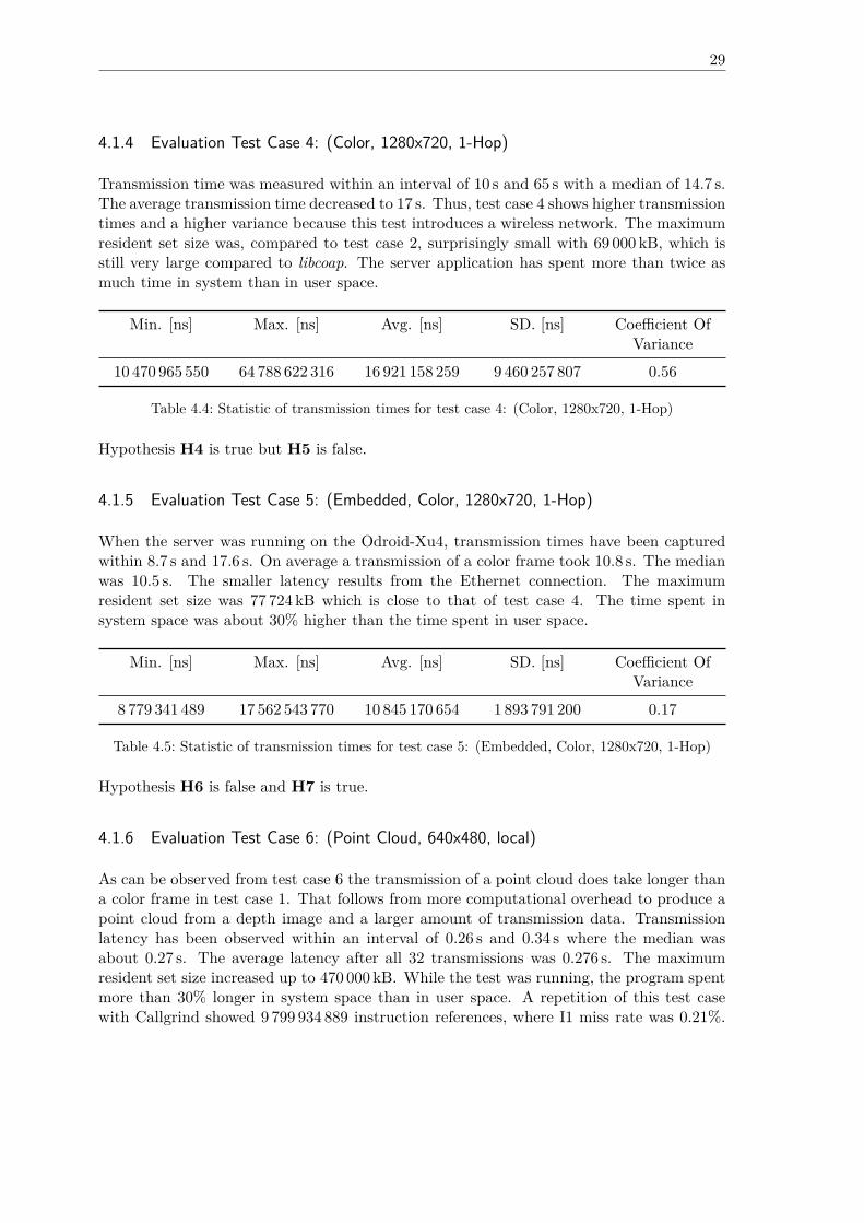
Transmission time was measured within an interval of 10 s and 65 s with a median of 14.7 s.The average transmission time decreased to 17 s. Thus, test case 4 shows higher transmissiontimes and a higher variance because this test introduces a wireless network. The maximumresident set size was, compared to test case 2, surprisingly small with 69 000 kB, which isstill very large compared to libcoap. The server application has spent more than twice asmuch time in system than in user space.
Min. [ns] Max. [ns] Avg. [ns] SD. [ns] Coefficient OfVariance
10 470 965 550 64 788 622 316 16 921 158 259 9 460 257 807 0.56
Table 4.4: Statistic of transmission times for test case 4: (Color, 1280x720, 1-Hop)
Hypothesis H4 is true but H5 is false.
4.1.5 Evaluation Test Case 5: (Embedded, Color, 1280x720, 1-Hop)
When the server was running on the Odroid-Xu4, transmission times have been capturedwithin 8.7 s and 17.6 s. On average a transmission of a color frame took 10.8 s. The medianwas 10.5 s. The smaller latency results from the Ethernet connection. The maximumresident set size was 77 724 kB which is close to that of test case 4. The time spent insystem space was about 30% higher than the time spent in user space.
Min. [ns] Max. [ns] Avg. [ns] SD. [ns] Coefficient OfVariance
8 779 341 489 17 562 543 770 10 845 170 654 1 893 791 200 0.17
Table 4.5: Statistic of transmission times for test case 5: (Embedded, Color, 1280x720, 1-Hop)
Hypothesis H6 is false and H7 is true.
4.1.6 Evaluation Test Case 6: (Point Cloud, 640x480, local)
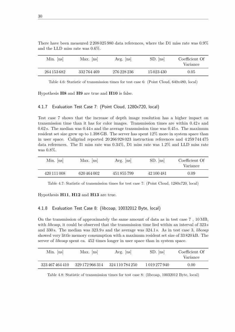
As can be observed from test case 6 the transmission of a point cloud does take longer thana color frame in test case 1. That follows from more computational overhead to produce apoint cloud from a depth image and a larger amount of transmission data. Transmissionlatency has been observed within an interval of 0.26 s and 0.34 s where the median wasabout 0.27 s. The average latency after all 32 transmissions was 0.276 s. The maximumresident set size increased up to 470 000 kB. While the test was running, the program spentmore than 30% longer in system space than in user space. A repetition of this test casewith Callgrind showed 9 799 934 889 instruction references, where I1 miss rate was 0.21%.
30
There have been measured 2 208 025 980 data references, where the D1 miss rate was 0.9%and the LLD miss rate was 0.6%.
Min. [ns] Max. [ns] Avg. [ns] SD. [ns] Coefficient OfVariance
264 153 682 332 764 469 276 228 236 15 023 430 0.05
Table 4.6: Statistic of transmission times for test case 6: (Point Cloud, 640x480, local)
Hypothesis H8 and H9 are true and H10 is false.
4.1.7 Evaluation Test Case 7: (Point Cloud, 1280x720, local)
Test case 7 shows that the increase of depth image resolution has a higher impact ontransmission time than it has for color images. Transmission times are within 0.42 s and0.62 s. The median was 0.44 s and the average transmission time was 0.45 s. The maximumresident set size grew up to 1.398 GB. The server has spent 12% more in system space thanin user space. Callgrind reported 20 266 928 023 instruction references and 4 259 744 475data references. The I1 miss rate was 0.34%, D1 miss rate was 1.2% and LLD miss ratewas 0.8%.
Min. [ns] Max. [ns] Avg. [ns] SD. [ns] Coefficient OfVariance
420 111 008 620 464 002 451 855 799 42 100 481 0.09
Table 4.7: Statistic of transmission times for test case 7: (Point Cloud, 1280x720, local)
Hypothesis H11, H12 and H13 are true.
4.1.8 Evaluation Test Case 8: (libcoap, 10032012 Byte, local)
On the transmission of approximately the same amount of data as in test case 7 , 10 MB,with libcoap, it could be observed that the transmission time lied within an interval of 323 sand 330 s. The median was 323.9 s and the average was 324.1 s. As in test case 3, libcoapshowed very little memory consumption with a maximum resident set size of 33 820 kB. Theserver of libcoap spent ca. 452 times longer in user space than in system space.
Min. [ns] Max. [ns] Avg. [ns] SD. [ns] Coefficient OfVariance
323 467 464 410 329 172 966 314 324 110 784 250 1 019 277 940 0.00
Table 4.8: Statistic of transmission times for test case 8: (libcoap, 10032012 Byte, local)
31
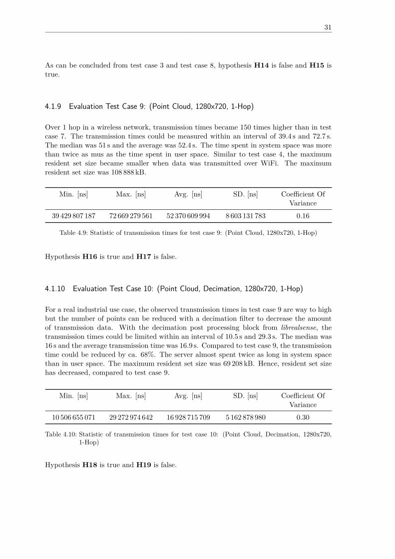
As can be concluded from test case 3 and test case 8, hypothesis H14 is false and H15 istrue.
4.1.9 Evaluation Test Case 9: (Point Cloud, 1280x720, 1-Hop)
Over 1 hop in a wireless network, transmission times became 150 times higher than in testcase 7. The transmission times could be measured within an interval of 39.4 s and 72.7 s.The median was 51 s and the average was 52.4 s. The time spent in system space was morethan twice as mus as the time spent in user space. Similar to test case 4, the maximumresident set size became smaller when data was transmitted over WiFi. The maximumresident set size was 108 888 kB.
Min. [ns] Max. [ns] Avg. [ns] SD. [ns] Coefficient OfVariance
39 429 807 187 72 669 279 561 52 370 609 994 8 603 131 783 0.16
Table 4.9: Statistic of transmission times for test case 9: (Point Cloud, 1280x720, 1-Hop)
Hypothesis H16 is true and H17 is false.
4.1.10 Evaluation Test Case 10: (Point Cloud, Decimation, 1280x720, 1-Hop)
For a real industrial use case, the observed transmission times in test case 9 are way to highbut the number of points can be reduced with a decimation filter to decrease the amountof transmission data. With the decimation post processing block from librealsense, thetransmission times could be limited within an interval of 10.5 s and 29.3 s. The median was16 s and the average transmission time was 16.9 s. Compared to test case 9, the transmissiontime could be reduced by ca. 68%. The server almost spent twice as long in system spacethan in user space. The maximum resident set size was 69 208 kB. Hence, resident set sizehas decreased, compared to test case 9.
Min. [ns] Max. [ns] Avg. [ns] SD. [ns] Coefficient OfVariance
10 506 655 071 29 272 974 642 16 928 715 709 5 162 878 980 0.30
Table 4.10: Statistic of transmission times for test case 10: (Point Cloud, Decimation, 1280x720,1-Hop)
Hypothesis H18 is true and H19 is false.
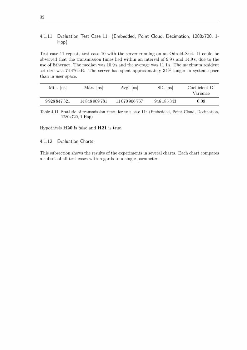
32
4.1.11 Evaluation Test Case 11: (Embedded, Point Cloud, Decimation, 1280x720, 1-Hop)
Test case 11 repeats test case 10 with the server running on an Odroid-Xu4. It could beobserved that the transmission times lied within an interval of 9.9 s and 14.9 s, due to theuse of Ethernet. The median was 10.9 s and the average was 11.1 s. The maximum residentset size was 74 476 kB. The server has spent approximately 34% longer in system spacethan in user space.
Min. [ns] Max. [ns] Avg. [ns] SD. [ns] Coefficient OfVariance
9 928 847 321 14 848 909 781 11 070 906 767 946 185 343 0.09
Table 4.11: Statistic of transmission times for test case 11: (Embedded, Point Cloud, Decimation,1280x720, 1-Hop)
Hypothesis H20 is false and H21 is true.
4.1.12 Evaluation Charts
This subsection shows the results of the experiments in several charts. Each chart comparesa subset of all test cases with regards to a single parameter.
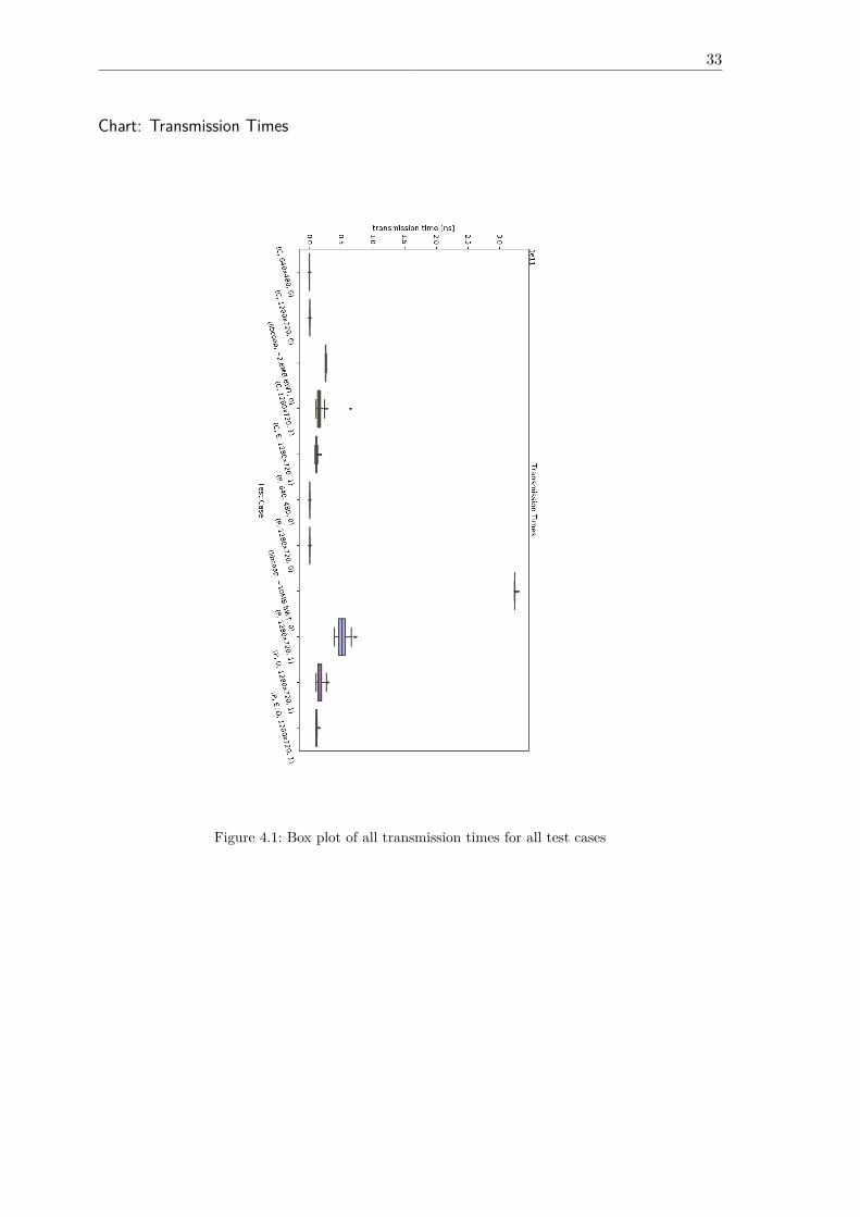
33
Chart: Transmission Times
Figure 4.1: Box plot of all transmission times for all test cases
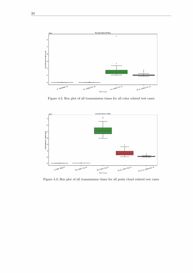
34
Figure 4.2: Box plot of all transmission times for all color related test cases
Figure 4.3: Box plot of all transmission times for all point cloud related test cases
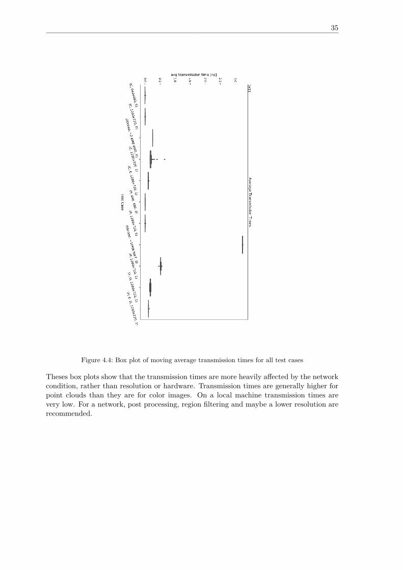
35
Figure 4.4: Box plot of moving average transmission times for all test cases
Theses box plots show that the transmission times are more heavily affected by the networkcondition, rather than resolution or hardware. Transmission times are generally higher forpoint clouds than they are for color images. On a local machine transmission times arevery low. For a network, post processing, region filtering and maybe a lower resolution arerecommended.
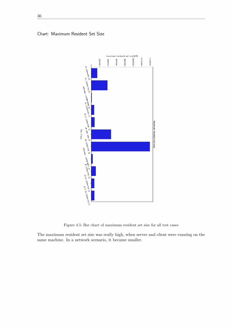
36
Chart: Maximum Resident Set Size
Figure 4.5: Bar chart of maximum resident set size for all test cases
The maximum resident set size was really high, when server and client were running on thesame machine. In a network scenario, it became smaller.
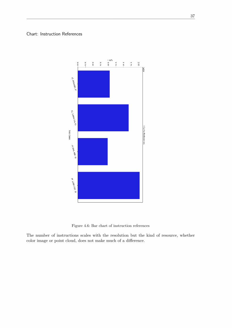
37
Chart: Instruction References
Figure 4.6: Bar chart of instruction references
The number of instructions scales with the resolution but the kind of resource, whethercolor image or point cloud, does not make much of a difference.
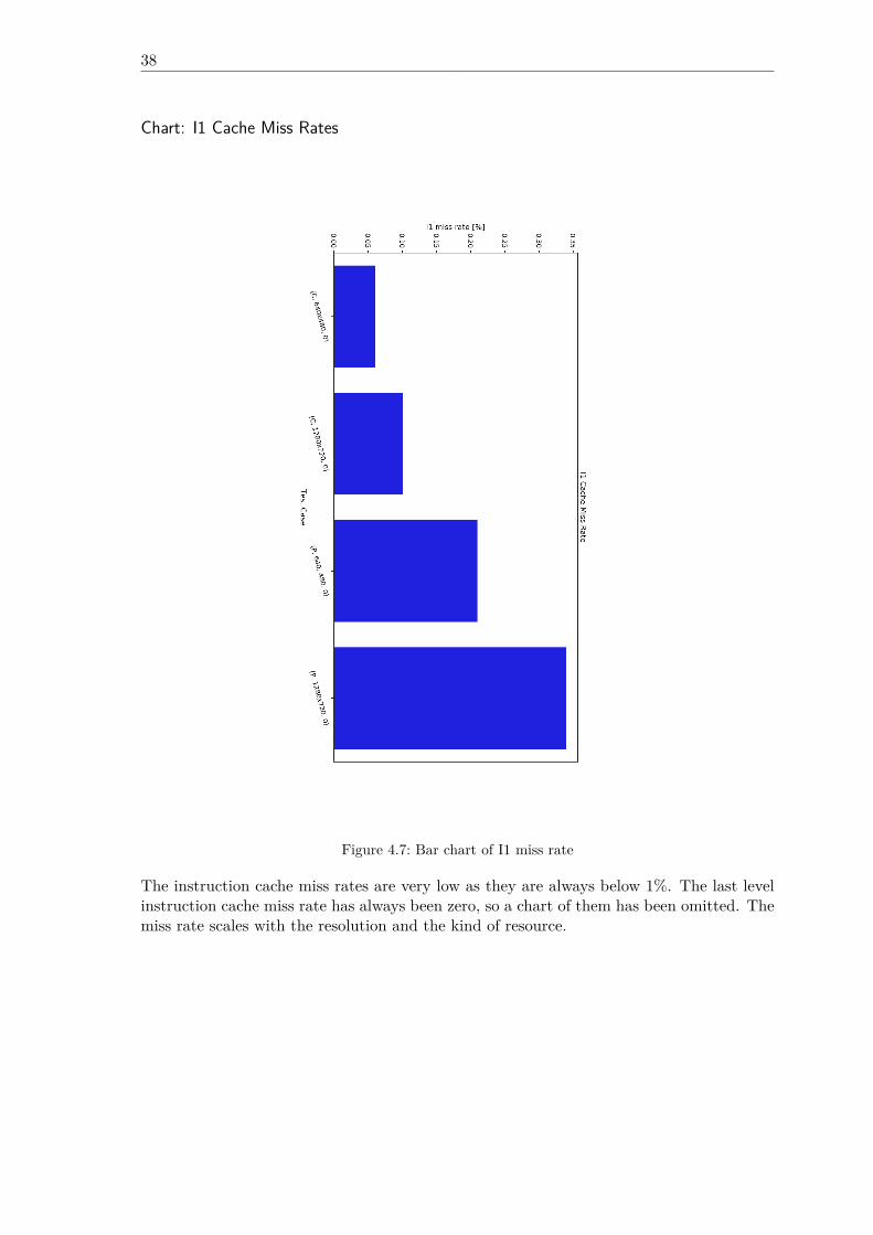
38
Chart: I1 Cache Miss Rates
Figure 4.7: Bar chart of I1 miss rate
The instruction cache miss rates are very low as they are always below 1%. The last levelinstruction cache miss rate has always been zero, so a chart of them has been omitted. Themiss rate scales with the resolution and the kind of resource.
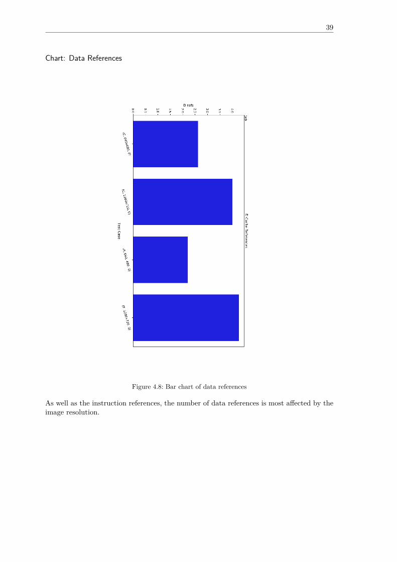
39
Chart: Data References
Figure 4.8: Bar chart of data references
As well as the instruction references, the number of data references is most affected by theimage resolution.
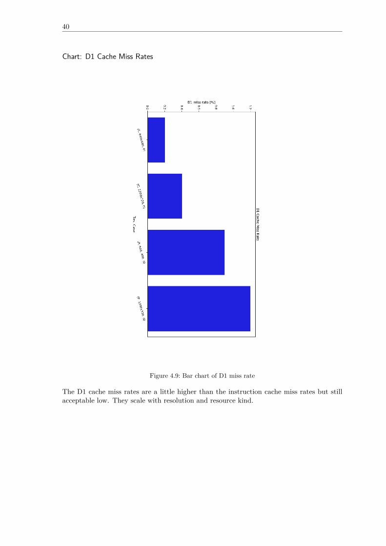
40
Chart: D1 Cache Miss Rates
Figure 4.9: Bar chart of D1 miss rate
The D1 cache miss rates are a little higher than the instruction cache miss rates but stillacceptable low. They scale with resolution and resource kind.
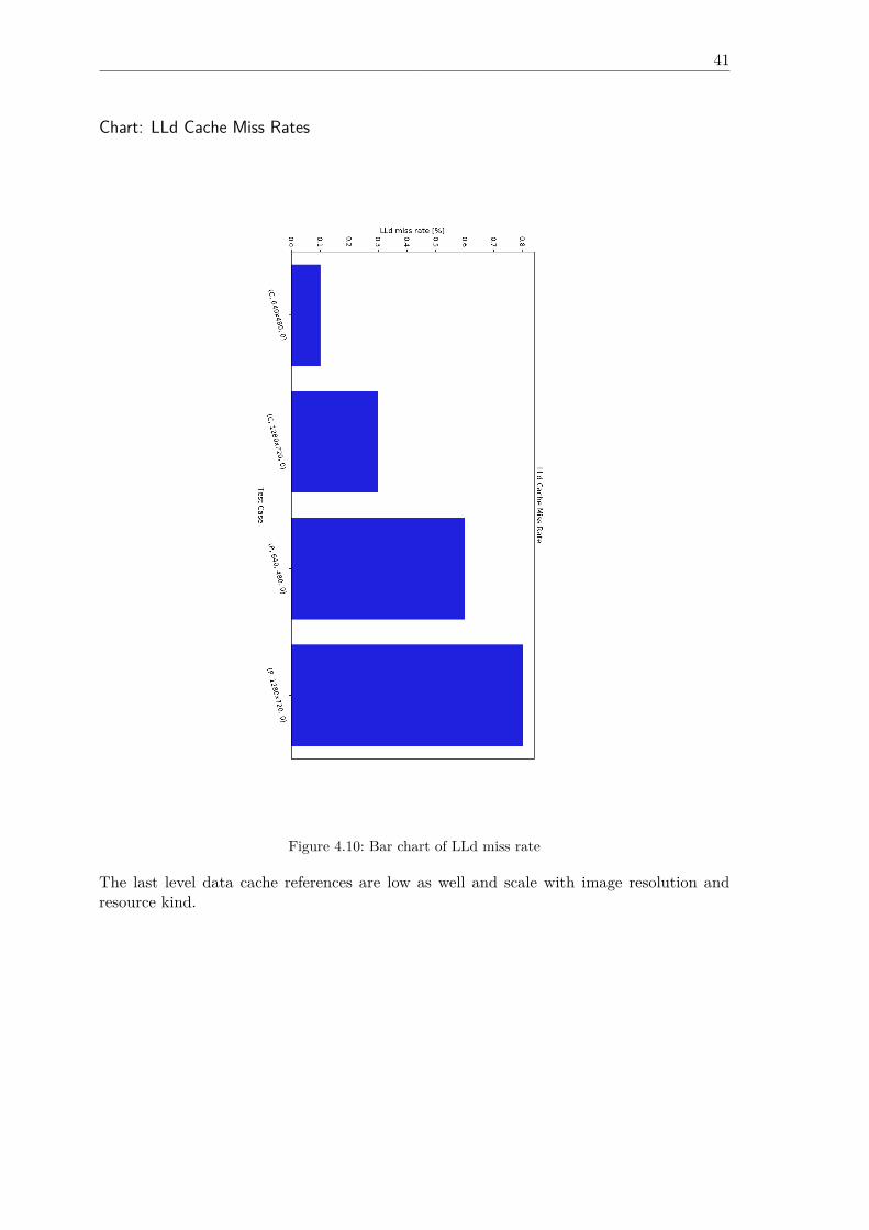
41
Chart: LLd Cache Miss Rates
Figure 4.10: Bar chart of LLd miss rate
The last level data cache references are low as well and scale with image resolution andresource kind.

CHAPTER 5
Conclusion
This chapter summarizes the advantages and disadvantages of using CoAP to transmit largeRGB-D sensor data. In the last section, an outlook of possible improvements and futureresearch will be given.
5.1 Summary
The goal of this thesis was to show that CoAP may function as a lightweight communicationprotocol to transmit RGB-D sensor data. As a contribution of this thesis, a simple scanapplication that uses the state of the art Intel RealSense D400 stereo depth sensors anda CoAP resource API have been proposed. Compared to libcoap, the application serverperforms very well in response time but leaves much potential in memory optimizations.The first transmission of a color or a depth packet usually takes longer than following trans-missions because the first grab with a cold sensor induces a short delay. Hence a highervariance follows. Experiments 4.1.4 and 4.1.9 have shown that the network overhead be-comes a bottleneck, when large data is being transferred with CoAP because of messageloss, retransmission timeouts and the nature of stop and wait. With default protocol pa-rameters, a client waits 3 s before it assumes that the first transmission did not reach theserver. An interesting approach to speed up transmission times in CoAP would be to setthe NSTART variable from RFC7252 [5] to a value greater than 1. Using the MQTT protocoldata can be transmitted faster due to TCP’s sliding window. For example a 10 MB filewas transferred in 0.04 s with the mosquitto_pub and mosquitto_sub applications from themosquitto MQTT broker, where publisher and subscriber have been running on the desktopcomputer, listed in Table 3.2. Compared to the results from experiment 4.1.8 where thefastest transmission was 0.42 s, MQTT would be about 9 times faster than CoAP. But effec-tively, all transmission times, except those measured with libcoap, from Section 4.1 includeprocessing delay, i.e. the time it takes to grab an image with the sensor. On constraintdevices the TCP sliding window might even be reduced to 1, which makes MQTT fall backto simple stop and wait. Tests have shown that the transmission of a point cloud gener-ally takes longer than the transmission of an image. However, scaling the resolution from640x480 to 1280x720 does not triple the transmission times because there is a constantprocessing overhead, including image grab time. For color frames, the higher resolution
44
scales the number of instructions by ca. 1.6 and the number of data references by 1.53. Forpoint cloud the number of instructions is scaled by 2.07 and the number of data referencedbecomes scaled by 1.93. Cache miss rates are mostly below 1%. Test case 10, related totest case 9, leads to the conclusion that decimation post processing improves transmissiontimes by ca. 68%. Test cases 5 and 11 show that the application may run on an embeddedsystem, such as the Odroid-Xu4 without suffering from higher response times. Generally,transmission times in a network are very high for full resolution images and point clouds.Thus, the conclusion of this thesis is that CoAP is only conditionally suitable to transmitlarge point cloud and image data if some point subsampling can be performed and a limited3D region of interest is known and a low resolution for color images can be use. Despitethe fact that CoAP runs over UDP, live streaming with default protocol parameters is nota suitable application for CoAP.
5.2 Future Work
Most significantly, future work includes to make use of a resource directory. The resourcedirectory serves as a central point to discover measurement groups, i.e. multicast groups ofCoAP endpoint whose cameras are configured to have a common coordinate system. Theresource directory should provide the current number of group members because the clientthat issues a multicast request to a measurement group must know how many endpoint itcan expect a response from. For now the client waits until the multicast response timeouthas expired, before computations are done. Secondly, a mechanism to synchronize the pointin time when multiple cameras take an image must be found. At the same endpoint onecould use sync-cables and across a network a time protocol could be used to coordinatedevice timers and the recipient should drop a response if it’s timestamps drifts away toofar.
Bibliography
[1] Statista. Internet of Things (IoT) connected devices installed base worldwide from2015 to 2025 (in billions). 2015. url: https://www.statista.com/statistics/471264/iot-number-of-connected-devices-worldwide/ (visited on 06/17/2019).
[2] Prasse et al. “New Approaches for Singularization in Logistic Applications Using LowCost 3D Sensors”. In: Sensing Technology: Current Status and Future Trends IV.Smart Sensors, Measurement and Instrumentation, vol 12. Springer, Cham (2015).
[3] Luis Barreto, António Amaral, and Teresa Pereira. “Industry 4.0 implications in lo-gistics: an overview”. In: Procedia Manufacturing 13 (Dec. 2017), pp. 1245–1252.
[4] Andrew Banksm et al. MQTT Version 5.0. Tech. rep. OASIS, 2018. url: http ://docs.oasis-open.org/mqtt/mqtt/v5.0/cs02/mqtt-v5.0-cs02.html (visitedon 06/17/2019).
[5] Zach Shelby, Klaus Hartke, and Carsten Bormann. The Constrained Application Pro-tocol (CoAP). RFC 7252. RFC Editor, June 2014. url: https://tools.ietf.org/rfc/rfc7252.txt (visited on 06/17/2019).
[6] Hong Linh Truong Andy Stanford-Clark. MQTT For Sensor Networks (MQTT-SN)Protocol Specification. Tech. rep. IBM, 2013.
[7] Statista authors. Anzahl der beförderten Pakete durch die Deutsche Post in Deutsch-land von 2016 bis 2018 (in Millionen Stück). url: https://de.statista.com/statistik/daten/studie/476935/umfrage/anzahl-der-befoerderten-pakete-durch-die-deutsche-post/ (visited on 06/17/2019).
[8] Fielding et al. Hypertext Transfer Protocol – HTTP/1.1. RFC 2616. RFC Editor, June1999. url: https://tools.ietf.org/rfc/rfc2616.txt (visited on 06/17/2019).
[9] Roy Thomas Fielding. Architectural Styles and the Design of Network-based SoftwareArchitectures. Tech. rep. UNIVERSITY OF CALIFORNIA, IRVINE, 2000. url: https://www.ics.uci.edu/~fielding/pubs/dissertation/top.htm (visited on06/17/2019).
[10] Berners-Lee et al. Uniform Resource Identifier (URI): Generic Syntax. RFC 3986.RFC Editor, Jan. 2005. url: https://tools.ietf.org/rfc/rfc3986.txt (visitedon 06/17/2019).
[11] Angelo P. Castellani et al. Guidelines for Mapping Implementations: HTTP to theConstrained Application Protocol (CoAP). RFC 8075. RFC Editor, Feb. 2017. url:https://tools.ietf.org/rfc/rfc8075.txt (visited on 06/17/2019).
46
[12] Michael Zollhöfer et al. “State of the Art on 3D Reconstruction with RGB‐D Cam-eras”. In: Computer Graphics Forum 37 (May 2018), pp. 625–652.
[13] Akbar Rahman and Esko Dijk. Group Communication for the Constrained ApplicationProtocol (CoAP). RFC 7390. RFC Editor, Oct. 2014. url: https://tools.ietf.org/rfc/rfc7390.txt (visited on 06/17/2019).
[14] Zach Shelby et al. CoRE Resource Directory - draft-ietf-core-resource-directory-20.Internet-Draft. RFC Editor, Mar. 2019. url: https://tools.ietf.org/id/draft-ietf-core-resource-directory-20.txt (visited on 06/17/2019).
[15] Cenk Gündoğan et al. “NDN, CoAP, and MQTT: A Comparative Measurement Studyin the IoT”. In: Proceedings of ACM ICN 2018 (2018). eprint: arXiv:1806.01444.
[16] Muhammad Harith Amaran et al. “A Comparison of Lightweight CommunicationProtocols in Robotic Applications”. In: Procedia Computer Science 76 (Dec. 2015),pp. 400–405.
[17] Dinesh Thangavel et al. “Performance evaluation of MQTT and CoAP via a commonmiddleware”. In: 2014 IEEE Ninth International Conference on Intelligent Sensors,Sensor Networks and Information Processing (ISSNIP). IEEE, Apr. 2014. url: https://doi.org/10.1109%2Fissnip.2014.6827678 (visited on 06/17/2019).
[18] Carsten Bormann and Zach Shelby. Block-Wise Transfers in the Constrained Appli-cation Protocol (CoAP). RFC 7959. RFC Editor, Aug. 2016. url: https://tools.ietf.org/rfc/rfc7959.txt (visited on 06/17/2019).
[19] Klaus Hartke. Observing Resources in the Constrained Application Protocol (CoAP).RFC 7641. RFC Editor, Sept. 2015. url: https://tools.ietf.org/rfc/rfc7641.txt (visited on 06/17/2019).
[20] Badis Djamaa and Ali Yachir. “A Proactive Trickle-based Mechanism for DiscoveringCoRE Resource Directories”. In: Procedia Computer Science 83 (Dec. 2016), pp. 115–122.
[21] Badis Djamaa et al. “Towards efficient distributed service discovery in low-power andlossy networks”. In: Wireless Networks 20 (June 2014), pp. 2437–2453.
[22] Markel Iglesias-Urkia, Adrián Orive, and Aitor Urbieta. “Analysis of CoAP Implemen-tations for Industrial Internet of Things: A Survey”. In: Procedia Computer Science109 (2017), pp. 188–195.
[23] Hagen Borstell et al. “Flexible 3D-Smart-Sensoren für Anwendungen in der Logistikund Produktion”. In: Dec. 2016, pp.103–112.
[24] Felix Endres et al. “3D Mapping with an RGB-D Camera”. In: IEEE TRANSAC-TIONS ON ROBOTICS 30 (2014).
[25] S. R. Fanello et al. “HyperDepth: Learning Depth from Structured Light withoutMatching”. In: 2016 IEEE Conference on Computer Vision and Pattern Recognition(CVPR). June 2016, pp. 5441–5450.
[26] Miles Hansard et al. Time-of-Flight Cameras: Principles, Methods and Applications.Springer Publishing Company, Incorporated, 2012.
47
[27] Wasenmüller O.and Stricker D. “A Comparison of Kinect V1 and V2 Depth Imagesin Terms of Accuracy and Precision”. In: Chen CS., Lu J., Ma KK. (eds) ComputerVision – ACCV 2016 Workshops. ACCV 2016. Lecture Notes in Computer Science,vol 10117. Springer, Cham (2017).
[28] Intel. Intel® RealSense™ Depth Camera D400-Series. Tech. rep. Intel, 2017. url:https://www.mouser.com/pdfdocs/Intel_D400_Series_Datasheet.pdf (visitedon 06/17/2019).
[29] Paul Munro and Antony P Gerdelan. “Stereo Vision Computer Depth Perception”.In: (May 2019).
[30] Anders Grunnet-Jepsen et al. “Projectors for Intel®RealSense™ Depth Cameras D4xx”.In: Intel Support (2018). url: https://www.intelrealsense.com/wp-content/uploads/2019/03/WhitePaper_on_Projectors_for_RealSense_D4xx_1.0.pdf(visited on 06/17/2019).
[31] Monica Carfagni et al. “Metrological and Critical Characterization of the Intel D415Stereo Depth Camera”. In: Sensors 19 (Jan. 2019), p. 489.
[32] Anders Grunnet-Jepsen, John N. Sweetser, and John Woodfill. “Best-Known-Methodsfor Tuning Intel® RealSenseTM D400 Depth Cameras for Best Performance”. In:Intel Support (2018). url: https://www.intel.com/content/dam/support/us/en/documents/emerging- technologies/intel- realsense- technology/BKMs_Tuning_RealSense_D4xx_Cam.pdf (visited on 06/17/2019).
[33] Philip Krejov and Anders Grunnet-Jepsen. “Intel RealSense Depth Camera over Eth-ernet”. In: Intel Support (2019). url: https : / / www . intelrealsense . com / wp -content/uploads/2019/03/Depth_Camera_powered_by_Ethernet_WhitePaper.pdf (visited on 06/17/2019).
[34] Anders Grunnet-Jepsen and Dave Tong. “Depth Post-Processing for Intel® RealSense™D400 Depth Cameras”. In: Intel Support (2018). url: https://www.intel.com/content / dam / support / us / en / documents / emerging - technologies / intel -realsense- technology/Intel- RealSense- Depth- PostProcess.pdf (visited on06/17/2019).
[35] Anders Grunnet-Jepsen et al. “Using the Intel® RealSenseTMDepth cameras D4xx inMulti-Camera Configurations”. In: Intel Support (2018). url: https://www.intel.com/content/dam/support/us/en/documents/emerging-technologies/intel-realsense-technology/RealSense_Multiple_Camera_WhitePaper.pdf (visited on06/17/2019).
[36] Intel. Intel®RealSense™ D400 SeriesCalibrationTools. Tech. rep. Intel, 2019. url:https://www.intel.com/content/dam/support/us/en/documents/emerging-technologies/intel-realsense-technology/RealSense_D400_Dyn_Calib_User_Guide.pdf (visited on 06/17/2019).
[37] Martin Wegner and Dr. Markus Kückelhaus. “LOW-COST SENSOR TECHNOL-OGY A DHL perspective on implications and use cases for the logistics industry”.In: DHL Customer Solutions & Innovation (2013). url: https : / / delivering -tomorrow.com/wp- content/uploads/2015/08/CSI_Studie_Low_Sensor.pdf(visited on 06/17/2019).
48 Appendix
[38] Rod Deakin. “3-D Coordinate Transformations”. In: 58 (Jan. 1999), pp. 223–34.[39] Dr. David L. Mills et al. Network Time Protocol Version 4: Protocol and Algorithms
Specification. RFC 5905. RFC Editor, June 2010. url: https://tools.ietf.org/rfc/rfc5905.txt (visited on 06/17/2019).
[40] Jakub Czyz et al. “Taming the 800 pound gorilla: The rise and decline of NTP DDoSattacks”. In: Proceedings of the ACM SIGCOMM Internet Measurement Conference,IMC (Nov. 2014), pp. 435–448.
[41] Zach Shelby. Constrained RESTful Environments (CoRE) Link Format. RFC 6690.RFC Editor, Aug. 2012. url: https://tools.ietf.org/rfc/rfc6690.txt (visitedon 06/17/2019).
[42] cJSON Developers. The cJSON Library. url: https://github.com/DaveGamble/cJSON (visited on 06/17/2019).
[43] RealSense Developers. The RealSense Library. url: https://github.com/IntelRealSense/librealsense (visited on 06/17/2019).
[44] Shinji Oomori, Takeshi Nishida, and Shuichi Kurogi. “Point cloud matching usingsingular value decomposition”. In: Artificial Life and Robotics 21 (June 2016), pp. 149–154.
[45] GSL Developers. The GNU Scientific Library. url: https://www.gnu.org/software/gsl/ (visited on 06/17/2019).
[46] ArUco Developers. The ArUco Library. url: https://sourceforge.net/projects/aruco/ (visited on 06/17/2019).
[47] RealSense Developers. GitHub WiKi of RealSense Library. url: https://github.com/IntelRealSense/librealsense/wiki (visited on 06/17/2019).
[48] Alberto López-Cerón and José M. Cañas. “Accuracy analysis of marker-based 3Dvisual localization”. In: Jornadas de Automática (2016).
[49] OpenCV Developers. The OpenCV Library. url: https://github.com/opencv/opencv/tree/3.4 (visited on 06/17/2019).
[50] OpenGL Developers. OpenGL. url: https://www.opengl.org/ (visited on 06/17/2019).[51] GLEW Developers. GLEW. url: http : / / glew . sourceforge . net/ (visited on
06/17/2019).[52] GLFW Developers. GLFW. url: https://www.glfw.org/ (visited on 06/17/2019).[53] glm Developers. glm. url: https://github.com/g-truc/glm (visited on 06/17/2019).
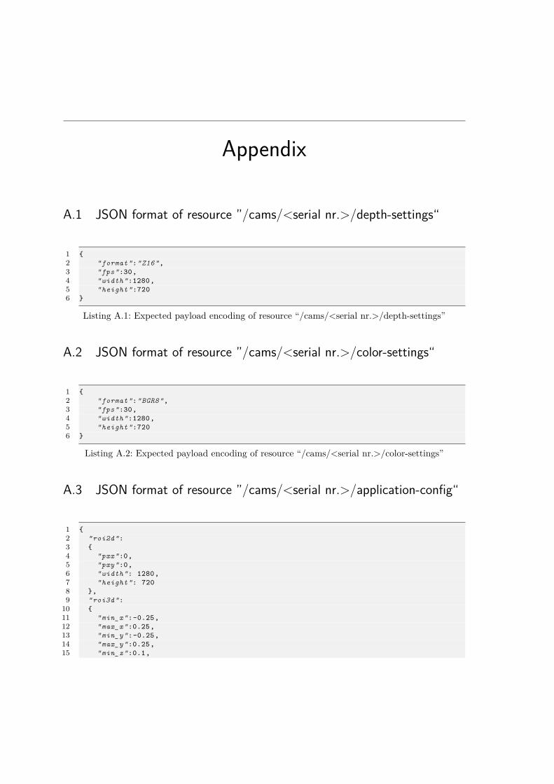
Appendix
A.1 JSON format of resource ”/cams/<serial nr.>/depth-settings“
1 {2 "format":"Z16",3 "fps":30,4 "width":1280,5 "height":7206 }
Listing A.1: Expected payload encoding of resource “/cams/<serial nr.>/depth-settings”
A.2 JSON format of resource ”/cams/<serial nr.>/color-settings“
1 {2 "format":"BGR8",3 "fps":30,4 "width":1280,5 "height":7206 }
Listing A.2: Expected payload encoding of resource “/cams/<serial nr.>/color-settings”
A.3 JSON format of resource ”/cams/<serial nr.>/application-config“
1 {2 "roi2d":3 {4 "pxx":0,5 "pxy":0,6 "width": 1280,7 "height": 7208 },9 "roi3d":
10 {11 "min_x":-0.25,12 "max_x":0.25,13 "min_y":-0.25,14 "max_y":0.25,15 "min_z":0.1,
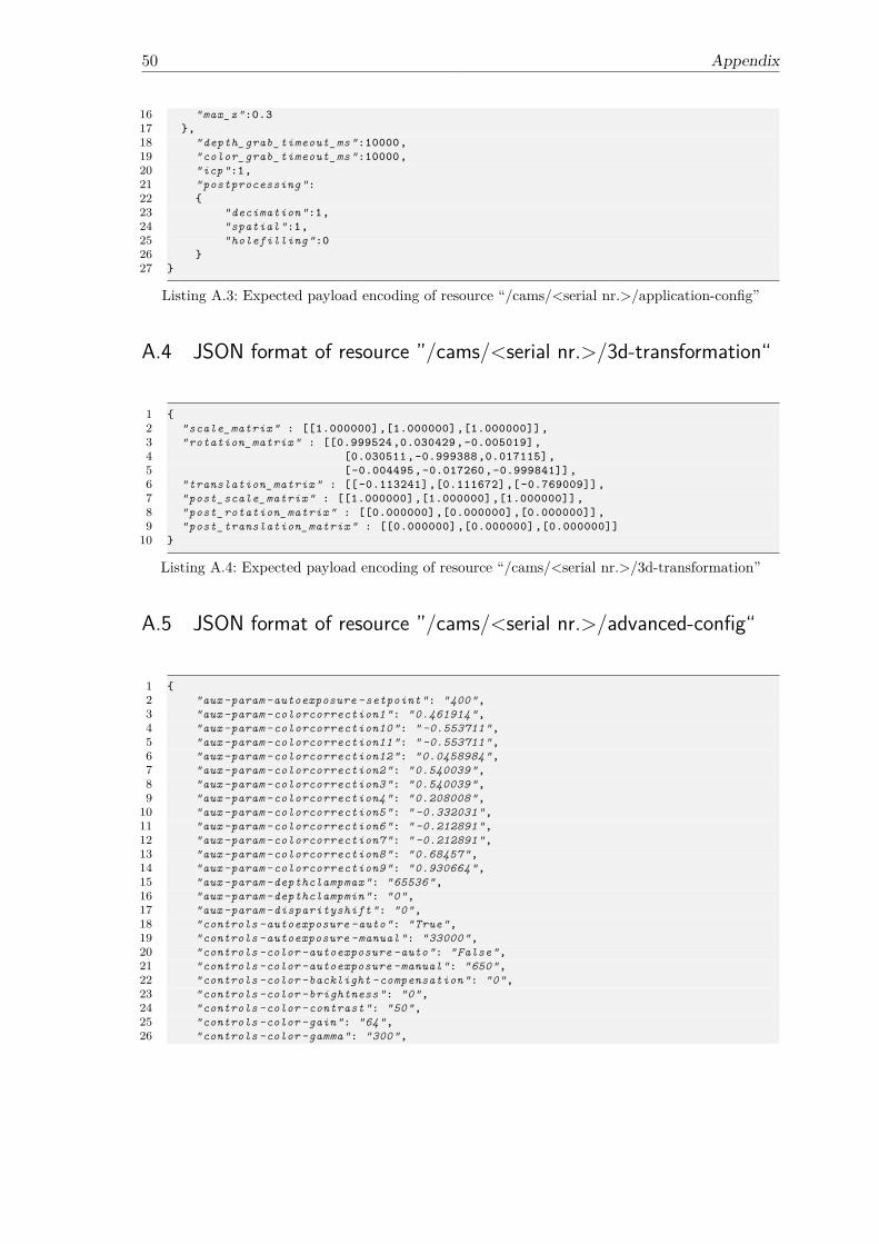
50 Appendix
16 "max_z":0.317 },18 "depth_grab_timeout_ms":10000,19 "color_grab_timeout_ms":10000,20 "icp":1,21 "postprocessing":22 {23 "decimation":1,24 "spatial":1,25 "holefilling":026 }27 }
Listing A.3: Expected payload encoding of resource “/cams/<serial nr.>/application-config”
A.4 JSON format of resource ”/cams/<serial nr.>/3d-transformation“
1 {2 "scale_matrix" : [[1.000000],[1.000000],[1.000000]],3 "rotation_matrix" : [[0.999524,0.030429,-0.005019],4 [0.030511,-0.999388,0.017115],5 [-0.004495,-0.017260,-0.999841]],6 "translation_matrix" : [[-0.113241],[0.111672],[-0.769009]],7 "post_scale_matrix" : [[1.000000],[1.000000],[1.000000]],8 "post_rotation_matrix" : [[0.000000],[0.000000],[0.000000]],9 "post_translation_matrix" : [[0.000000],[0.000000],[0.000000]]
10 }
Listing A.4: Expected payload encoding of resource “/cams/<serial nr.>/3d-transformation”
A.5 JSON format of resource ”/cams/<serial nr.>/advanced-config“
1 {2 "aux-param -autoexposure -setpoint": "400",3 "aux-param -colorcorrection1": "0.461914",4 "aux-param -colorcorrection10": " -0.553711",5 "aux-param -colorcorrection11": " -0.553711",6 "aux-param -colorcorrection12": "0.0458984",7 "aux-param -colorcorrection2": "0.540039",8 "aux-param -colorcorrection3": "0.540039",9 "aux-param -colorcorrection4": "0.208008",
10 "aux-param -colorcorrection5": " -0.332031",11 "aux-param -colorcorrection6": " -0.212891",12 "aux-param -colorcorrection7": " -0.212891",13 "aux-param -colorcorrection8": "0.68457",14 "aux-param -colorcorrection9": "0.930664",15 "aux-param -depthclampmax": "65536",16 "aux-param -depthclampmin": "0",17 "aux-param -disparityshift": "0",18 "controls -autoexposure -auto": "True",19 "controls -autoexposure -manual": "33000",20 "controls -color -autoexposure -auto": "False",21 "controls -color -autoexposure -manual": "650",22 "controls -color -backlight -compensation": "0",23 "controls -color -brightness": "0",24 "controls -color -contrast": "50",25 "controls -color -gain": "64",26 "controls -color -gamma": "300",
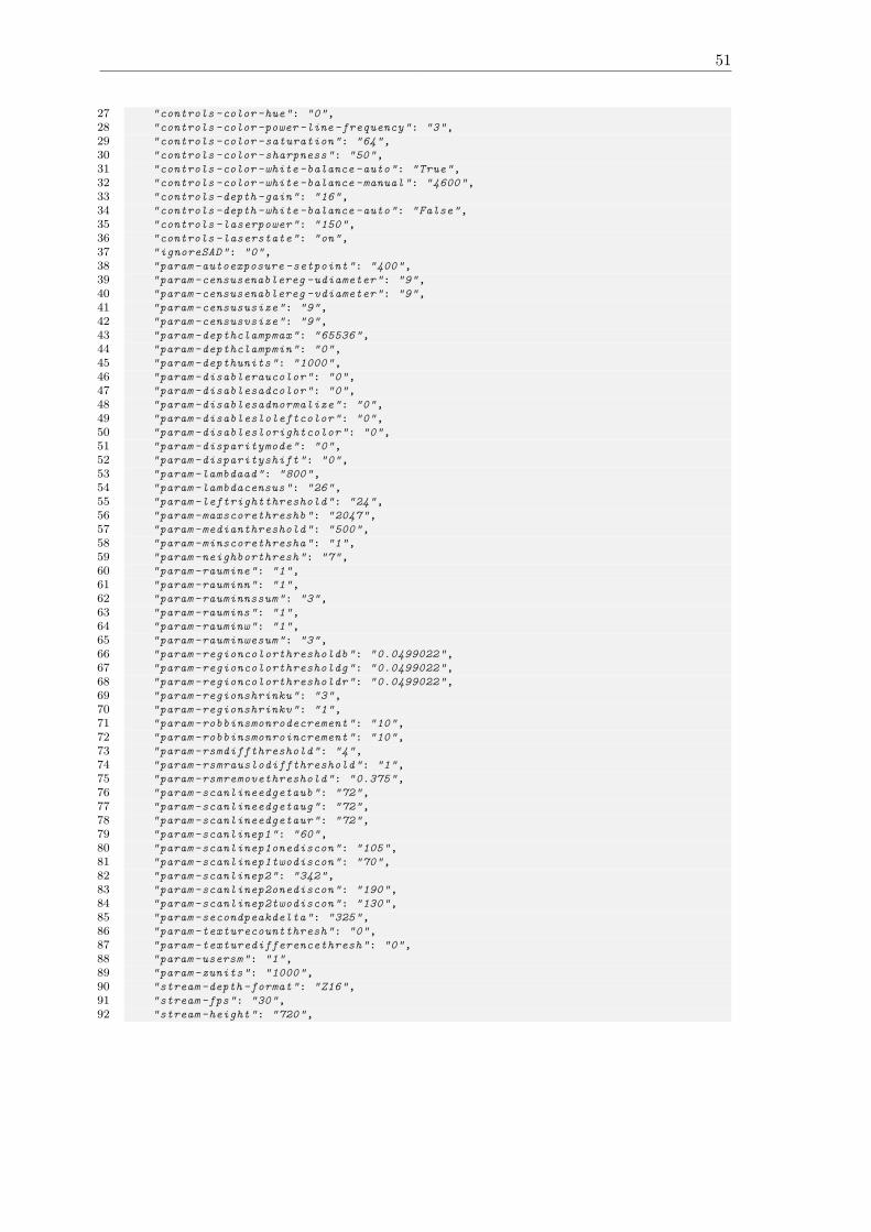
51
27 "controls -color -hue": "0",28 "controls -color -power -line-frequency": "3",29 "controls -color -saturation": "64",30 "controls -color -sharpness": "50",31 "controls -color -white -balance -auto": "True",32 "controls -color -white -balance -manual": "4600",33 "controls -depth -gain": "16",34 "controls -depth -white -balance -auto": "False",35 "controls -laserpower": "150",36 "controls -laserstate": "on",37 "ignoreSAD": "0",38 "param -autoexposure -setpoint": "400",39 "param -censusenablereg -udiameter": "9",40 "param -censusenablereg -vdiameter": "9",41 "param -censususize": "9",42 "param -censusvsize": "9",43 "param -depthclampmax": "65536",44 "param -depthclampmin": "0",45 "param -depthunits": "1000",46 "param -disableraucolor": "0",47 "param -disablesadcolor": "0",48 "param -disablesadnormalize": "0",49 "param -disablesloleftcolor": "0",50 "param -disableslorightcolor": "0",51 "param -disparitymode": "0",52 "param -disparityshift": "0",53 "param -lambdaad": "800",54 "param -lambdacensus": "26",55 "param -leftrightthreshold": "24",56 "param -maxscorethreshb": "2047",57 "param -medianthreshold": "500",58 "param -minscorethresha": "1",59 "param -neighborthresh": "7",60 "param -raumine": "1",61 "param -rauminn": "1",62 "param -rauminnssum": "3",63 "param -raumins": "1",64 "param -rauminw": "1",65 "param -rauminwesum": "3",66 "param -regioncolorthresholdb": "0.0499022",67 "param -regioncolorthresholdg": "0.0499022",68 "param -regioncolorthresholdr": "0.0499022",69 "param -regionshrinku": "3",70 "param -regionshrinkv": "1",71 "param -robbinsmonrodecrement": "10",72 "param -robbinsmonroincrement": "10",73 "param -rsmdiffthreshold": "4",74 "param -rsmrauslodiffthreshold": "1",75 "param -rsmremovethreshold": "0.375",76 "param -scanlineedgetaub": "72",77 "param -scanlineedgetaug": "72",78 "param -scanlineedgetaur": "72",79 "param -scanlinep1": "60",80 "param -scanlinep1onediscon": "105",81 "param -scanlinep1twodiscon": "70",82 "param -scanlinep2": "342",83 "param -scanlinep2onediscon": "190",84 "param -scanlinep2twodiscon": "130",85 "param -secondpeakdelta": "325",86 "param -texturecountthresh": "0",87 "param -texturedifferencethresh": "0",88 "param -usersm": "1",89 "param -zunits": "1000",90 "stream -depth -format": "Z16",91 "stream -fps": "30",92 "stream -height": "720",
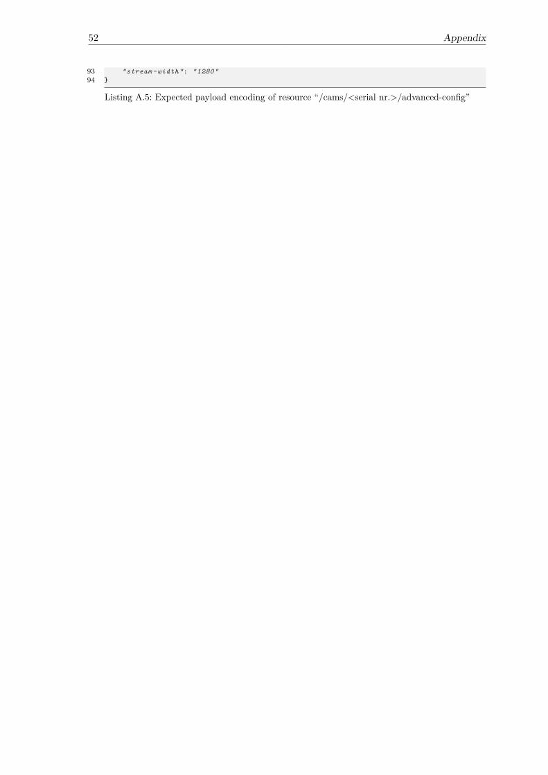
52 Appendix
93 "stream -width": "1280"94 }
Listing A.5: Expected payload encoding of resource “/cams/<serial nr.>/advanced-config”

I herewith assure that I wrote the present thesis titled 3D Scan Applications in Logistics:Using CoAP with RGB-D Cameras independently, that the thesis has not been partiallyor fully submitted as graded academic work and that I have used no other means than theones indicated. I have indicated all parts of the work in which sources are used accordingto their wording or to their meaning.I am aware of the fact that violations of copyright can lead to injunctive relief and claimsfor damages of the author as well as a penalty by the law enforcement agency.
Magdeburg, August 6, 2020(Fabian Hüßler)