Embed Size (px)
Citation preview
616 01 1019 00 10/17/14
Communicating Wall ControlWith Wi--FiR CapabilityInstallation ManualTSTAT0201CW
U.S. Patent No. 7,243,004U.S. Patent No. 7,775,452
C O M M U N I C A T I N G S Y S T E M
R
All trademarks are the property of the respective owners.
Wi-Fi® is a registered trademark of the Wi-Fi Alliance Corporation.

2 616 01 1019 00
Safety Considerations 6. . . . . . . . . . . . . . . . . . . . . . . . . . . . . . .Introduction 7. . . . . . . . . . . . . . . . . . . . . . . . . . . . . . . . . . . . . . . . .Quick Start 9. . . . . . . . . . . . . . . . . . . . . . . . . . . . . . . . . . . . . . . . .
Set Day and Time 9. . . . . . . . . . . . . . . . . . . . . . . . . . . . . . . . .Set Schedule for All Days 11. . . . . . . . . . . . . . . . . . . . . . . . .
Installation 14. . . . . . . . . . . . . . . . . . . . . . . . . . . . . . . . . . . . . . . .Overview 14. . . . . . . . . . . . . . . . . . . . . . . . . . . . . . . . . . . . . . .Check Equipment 15. . . . . . . . . . . . . . . . . . . . . . . . . . . . . . . .Location 15. . . . . . . . . . . . . . . . . . . . . . . . . . . . . . . . . . . . . . . .
Wall Control 15. . . . . . . . . . . . . . . . . . . . . . . . . . . . . . . . . .Remote Room Sensors 16. . . . . . . . . . . . . . . . . . . . . . . .
Wiring Considerations 17. . . . . . . . . . . . . . . . . . . . . . . . . . . .Shielded Wire 19. . . . . . . . . . . . . . . . . . . . . . . . . . . . . . . . .Non-communicating equipment 19. . . . . . . . . . . . . . . . .
Mounting 19. . . . . . . . . . . . . . . . . . . . . . . . . . . . . . . . . . . . . . .Humidifier Connection 21. . . . . . . . . . . . . . . . . . . . . . . . . . . .
Bypass Humidifiers 21. . . . . . . . . . . . . . . . . . . . . . . . . . . .Fan Powered Humidifiers 21. . . . . . . . . . . . . . . . . . . . . . .
Commissioning 22. . . . . . . . . . . . . . . . . . . . . . . . . . . . . . . . . . . .Communicating System Overview 22. . . . . . . . . . . . . . . . . .Selecting Accessories 24. . . . . . . . . . . . . . . . . . . . . . . . . . . .Selecting Indoor Unit 24. . . . . . . . . . . . . . . . . . . . . . . . . . . . .Equipment Summary 26. . . . . . . . . . . . . . . . . . . . . . . . . . . . .Brand Selection 26. . . . . . . . . . . . . . . . . . . . . . . . . . . . . . . . .Current Software Version 27. . . . . . . . . . . . . . . . . . . . . . . . .Software Updates 27. . . . . . . . . . . . . . . . . . . . . . . . . . . . . . . .Setting Up Remote Access and Wi-Fi® Connection 28. .
3616 01 1019 00
Install/Service Menus – Communicating andNon-Communicating Mode 30. . . . . . . . . . . . . . . . . . . . . . . . . .
Equipment Summary Menu 31. . . . . . . . . . . . . . . . . . . . . . .Service Menus 32. . . . . . . . . . . . . . . . . . . . . . . . . . . . . . . . . .
Status 32. . . . . . . . . . . . . . . . . . . . . . . . . . . . . . . . . . . . . . . .Heat Stage (Furnace) 32. . . . . . . . . . . . . . . . . . . . . . . .Electric Heat (Fan Coil) 32. . . . . . . . . . . . . . . . . . . . . .Airflow CFM 32. . . . . . . . . . . . . . . . . . . . . . . . . . . . . . . .Inducer RPM (Modulating furnaces only) 32. . . . . . .Blower RPM (Modulating furnaces only) 33. . . . . . . .Lockout Timer 33. . . . . . . . . . . . . . . . . . . . . . . . . . . . . .Heat Pump/AC Status 33. . . . . . . . . . . . . . . . . . . . . . .Stage: (Heat/Cool) 33. . . . . . . . . . . . . . . . . . . . . . . . . .Defrost 33. . . . . . . . . . . . . . . . . . . . . . . . . . . . . . . . . . . .Outdoor Coil Temp 33. . . . . . . . . . . . . . . . . . . . . . . . . .
Last 10 System Faults 33. . . . . . . . . . . . . . . . . . . . . . . . .Lifetime Run History 34. . . . . . . . . . . . . . . . . . . . . . . . . . .Cycle Counters 34. . . . . . . . . . . . . . . . . . . . . . . . . . . . . . . .Run Timers 34. . . . . . . . . . . . . . . . . . . . . . . . . . . . . . . . . . .Filter Reminder 26. . . . . . . . . . . . . . . . . . . . . . . . . . . . . . . .
Auto Mode Enable 36. . . . . . . . . . . . . . . . . . . . . . . . . . . . . . .Room Temperature Sensing 37. . . . . . . . . . . . . . . . . . . . . .Reversing Valve 38. . . . . . . . . . . . . . . . . . . . . . . . . . . . . . . . .English/Metric Display 39. . . . . . . . . . . . . . . . . . . . . . . . . . . .Fan on with W 40. . . . . . . . . . . . . . . . . . . . . . . . . . . . . . . . . . .Cooling Lockout 41. . . . . . . . . . . . . . . . . . . . . . . . . . . . . . . . .Auxiliary Heat Lockout 42. . . . . . . . . . . . . . . . . . . . . . . . . . . .Heat Pump Lockout 43. . . . . . . . . . . . . . . . . . . . . . . . . . . . . .
4 616 01 1019 00
Minimum Cooling Setpoint 44. . . . . . . . . . . . . . . . . . . . . . . .Maximum Heating Setpoint 45. . . . . . . . . . . . . . . . . . . . . . . .Outdoor Air Temperature Offset 46. . . . . . . . . . . . . . . . . . .Room Air Temperature Offset 47. . . . . . . . . . . . . . . . . . . . .Smart Recovery 48. . . . . . . . . . . . . . . . . . . . . . . . . . . . . . . . .Setpoint Deadband 49. . . . . . . . . . . . . . . . . . . . . . . . . . . . . .Cycles Per Hour 50. . . . . . . . . . . . . . . . . . . . . . . . . . . . . . . . .Auto Changeover Timer 51. . . . . . . . . . . . . . . . . . . . . . . . . .Time Between Fuel Types 52. . . . . . . . . . . . . . . . . . . . . . . .Humidity Offset 53. . . . . . . . . . . . . . . . . . . . . . . . . . . . . . . . . .Programming On/Off 54. . . . . . . . . . . . . . . . . . . . . . . . . . . . .Reset to Factory Defaults 55. . . . . . . . . . . . . . . . . . . . . . . . .Dealer Info 56. . . . . . . . . . . . . . . . . . . . . . . . . . . . . . . . . . . . . .Service Reminder 57. . . . . . . . . . . . . . . . . . . . . . . . . . . . . . . .
Install/Service Menus - Communicating Equipment 57. . . . .Setup Menu 57. . . . . . . . . . . . . . . . . . . . . . . . . . . . . . . . . . . . .
English/Metric Display 58. . . . . . . . . . . . . . . . . . . . . . .Airflow 59. . . . . . . . . . . . . . . . . . . . . . . . . . . . . . . . . . . . . . .
Heating Airflow 59. . . . . . . . . . . . . . . . . . . . . . . . . . . . .Furnace / Fancoil Heating Airflow 59. . . . . . . . . . . . .Heat Pump Heating Airflow 60. . . . . . . . . . . . . . . . . . .Cooling Airflow 60. . . . . . . . . . . . . . . . . . . . . . . . . . . . .Dehum Airflow 60. . . . . . . . . . . . . . . . . . . . . . . . . . . . . .Furnace Airflow (Capacity) Limiting 61. . . . . . . . . . . .Dehum Drain 61. . . . . . . . . . . . . . . . . . . . . . . . . . . . . . .Off Delay 61. . . . . . . . . . . . . . . . . . . . . . . . . . . . . . . . . .Low Heat Rise 62. . . . . . . . . . . . . . . . . . . . . . . . . . . . . .Defrost Interval 63. . . . . . . . . . . . . . . . . . . . . . . . . . . . .
5616 01 1019 00
Defrost With Furnace 64. . . . . . . . . . . . . . . . . . . . . . . .Quiet Shift 64. . . . . . . . . . . . . . . . . . . . . . . . . . . . . . . . .Zones 65. . . . . . . . . . . . . . . . . . . . . . . . . . . . . . . . . . . . .Zone Weighting 66. . . . . . . . . . . . . . . . . . . . . . . . . . . . .Zone Airflow Control 67. . . . . . . . . . . . . . . . . . . . . . . . .Bypass 68. . . . . . . . . . . . . . . . . . . . . . . . . . . . . . . . . . . .Airflow Capacity 68. . . . . . . . . . . . . . . . . . . . . . . . . . . .Damper Type 69. . . . . . . . . . . . . . . . . . . . . . . . . . . . . . .
Leaving Air Sensor (LAS) 70. . . . . . . . . . . . . . . . . . . . . . .Disable Zoning 70. . . . . . . . . . . . . . . . . . . . . . . . . . . . . . . .Damper Timing 71. . . . . . . . . . . . . . . . . . . . . . . . . . . . . . . .HRV - Heat Recovery Maintenance 71. . . . . . . . . . . . . .Daughter Board 72. . . . . . . . . . . . . . . . . . . . . . . . . . . . . . .Operational Information 73. . . . . . . . . . . . . . . . . . . . . . . .Auto Mode 73. . . . . . . . . . . . . . . . . . . . . . . . . . . . . . . . . . . .
Setpoint Deadband 73. . . . . . . . . . . . . . . . . . . . . . . . . .Offsets 73. . . . . . . . . . . . . . . . . . . . . . . . . . . . . . . . . . . .Cycles Per Hour 73. . . . . . . . . . . . . . . . . . . . . . . . . . . .
Programming 74. . . . . . . . . . . . . . . . . . . . . . . . . . . . . . . . .Smart Recovery 74. . . . . . . . . . . . . . . . . . . . . . . . . . . . . . .
Appendix – Wiring Diagrams 75. . . . . . . . . . . . . . . . . . . . . . . . .
6 616 01 1019 00
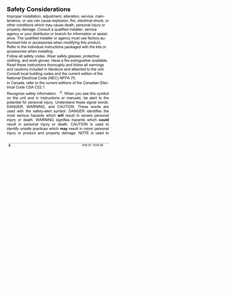
Safety ConsiderationsImproper installation, adjustment, alteration, service, main-tenance, or use can cause explosion, fire, electrical shock, orother conditions which may cause death, personal injury orproperty damage. Consult a qualified installer, serviceagency or your distributor or branch for information or assist-ance. The qualified installer or agency must use factory-au-thorized kits or accessories when modifying this product.Refer to the individual instructions packaged with the kits oraccessories when installing.Follow all safety codes. Wear safety glasses, protectiveclothing, and work gloves. Have a fire extinguisher available.Read these instructions thoroughly and follow all warningsand cautions included in literature and attached to the unit.Consult local building codes and the current edition of theNational Electrical Code (NEC) NFPA 70.In Canada, refer to the current editions of the Canadian Elec-trical Code CSA C22.1.
Recognize safety information. When you see this symbolon the unit and in instructions or manuals, be alert to thepotential for personal injury. Understand these signal words:DANGER, WARNING, and CAUTION. These words areused with the safety-alert symbol. DANGER identifies themost serious hazards which will result in severe personalinjury or death. WARNING signifies hazards which couldresult in personal injury or death. CAUTION is used toidentify unsafe practices which may result in minor personalinjury or product and property damage. NOTE is used to
7616 01 1019 00
highlight suggestions which will result in enhancedinstallation, reliability, or operation.
IntroductionThe Observer® communicating system consists of severalintelligent communicating components which includes theObserver® Wall Control, and Observer System HVACequipment such as, variable speed furnace or fan coil,2-stage AC or HP, which continually communicate with eachother via a four-wire communication bus. Commands, oper-ating conditions, and other data are passed continuallybetween components over the communication bus. The res-ult is an enhanced level of comfort, versatility, and simplicity.All communicating furnaces or fan coils are variable-speedand multi-stage for maximum flexibility, efficiency, and com-fort. They support controlled humidification, dehumidification,and air quality control. Either an Observer communicating, ora standard 24VAC controlled outdoor unit may be used.When using conventional, single-stage outdoor units, thecommunicating furnace (single-stage AC unit), or fan coil(single-stage HP) provides the 24 volt signals needed to con-trol them. Add the accessory daughter board to the systemto control other types of conventional outdoor units. All sys-tem components are controlled through the wall mountedObserver Control, which replaces the conventional thermo-stat and provides the homeowner with a single wall controlfor all features of the system.The Observer Communicating Control with Wi-FiR networkcompatibility allows connection of this system to the Internetvia a home Wi-FiR network. See the Owner's Manual forinformation on connecting the wall control to the home Wi-Fi
8 616 01 1019 00
network, and the MyObserverComfort web server. See laterin these Installation Instructions for information on applyingthe accessory NAXA00101WA wireless access point, if theexisting home network is incompatible with this product.
The ability to remotely access and adjust the settings ofthe Observer® wall control with the MyObserverComfortweb and mobile applications is dependent on the com-patibility of the user’s computer/network or mobile de-vice, the Observer wall control, and/or the MyObserver-Comfort web server with, and the availability of, theuser’s Internet service provider or mobile device carrierservice. International Comfort Products makes no repre-sentations or warranties, express or implied, including,to the extent permitted by applicable law, any impliedwarranty of merchantability or fitness for a particularpurpose or use, about the compatibility of the user’scomputer/network, or mobile device, with the Observerwall control, and/or the MyObserverComfort web server,with, and the availability of, the user’s Internet serviceprovider or mobile device carrier service, or that theability to remotely access and adjust the settings of theObserver wall control will not be negatively affected bythe network-related modifications, upgrades, or similaractivity of the user’s Internet service provider or mobiledevice carrier service.
9616 01 1019 00
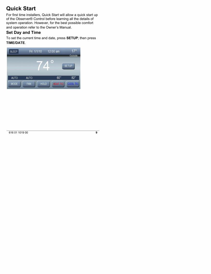
Quick StartFor first time installers, Quick Start will allow a quick start upof the Observer® Control before learning all the details ofsystem operation. However, for the best possible comfortand operation refer to the Owner’s Manual.
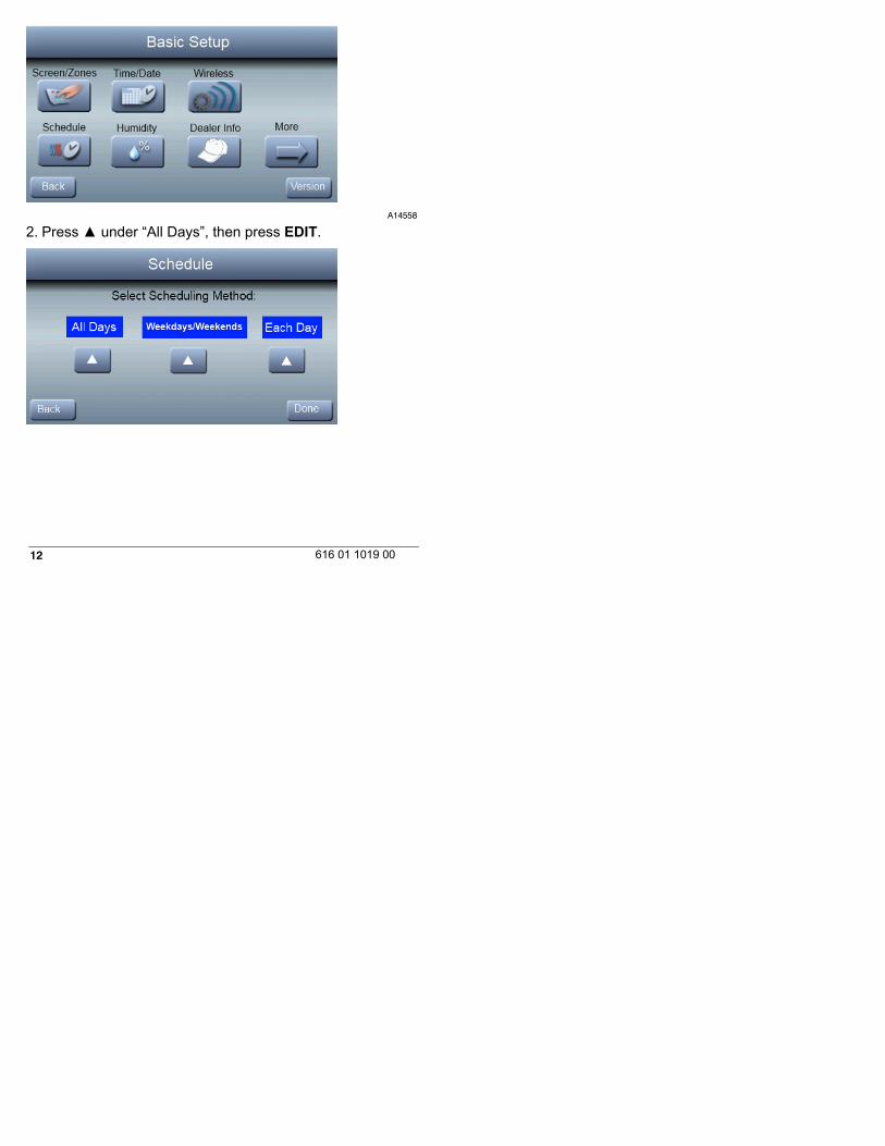
Set Day and TimeTo set the current time and date, press SETUP; then pressTIME/DATE.

10 616 01 1019 00
A14558
Under date, you can select the month, day, or year buttons;then use the ▲ and ▼ to select the appropriate date. . Un-der time, you can select the hour, minute, and am/pm; thenuse the ▲ and ▼ to select the appropriate time. You alsohave the option of selecting between a 12 HR or 24 HR clockformat. Finally, you can choose whether you observe daylight savings time by pressing the ON or OFF button. Press
11616 01 1019 00
DONE to save and exit the information that you haveentered.
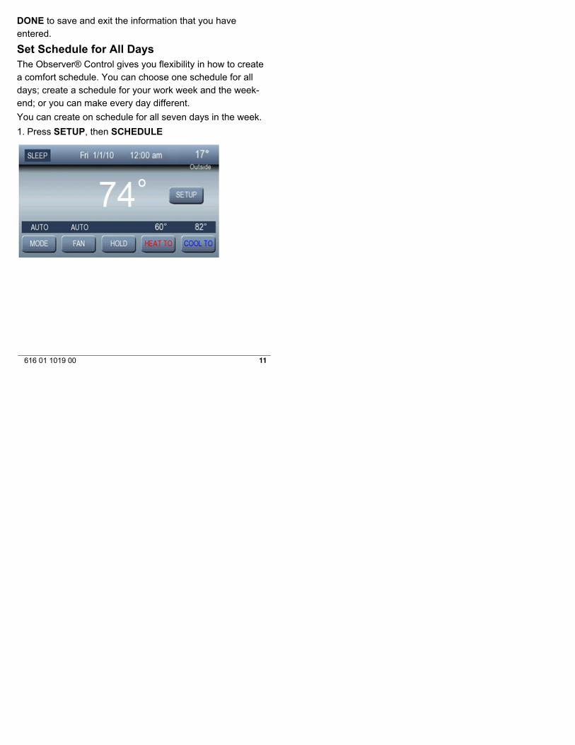
Set Schedule for All DaysThe Observer® Control gives you flexibility in how to createa comfort schedule. You can choose one schedule for alldays; create a schedule for your work week and the week-end; or you can make every day different.
You can create on schedule for all seven days in the week.
1. Press SETUP, then SCHEDULE
12 616 01 1019 00
A14558
2. Press ▲ under “All Days”, then press EDIT.
13616 01 1019 00
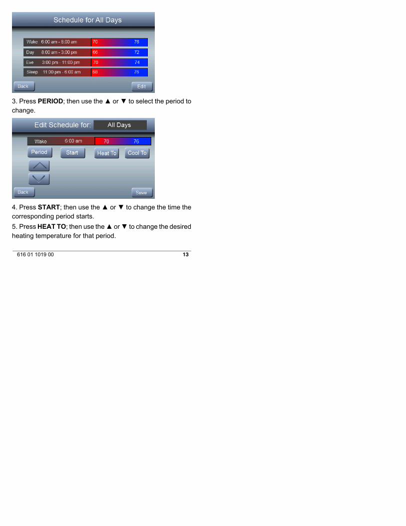
3. Press PERIOD; then use the ▲ or ▼ to select the period tochange.
4. Press START; then use the ▲ or ▼ to change the time thecorresponding period starts.
5. Press HEAT TO; then use the▲ or▼ to change the desiredheating temperature for that period.

14 616 01 1019 00
6. Press COOL TO; then use the▲ or▼ to change the desiredheating temperature for that period.
7. Press DONE after you have completed your edits.
8. Press SAVE to save your new schedule and exit (or pressCANCEL to exit without saving.)
NOTE: See Owners manual for further details of setting upschedules.
InstallationOverviewThis instruction covers installation of the Observer® Controlonly. Physical installation instructions for the indoor and out-door equipment and accessories are provided with each unit.Setup, commissioning, operation, and troubleshooting of thecommunicating system are covered only in this installationinstruction. It is the guide to connecting the system compon-ents and commissioning the system once all physical com-ponents are installed. Special screen prompts and start-upcapabilities are provided in the communicating system tosimplify and automate the initial commissioning of the sys-tem.
S Install Observer Control according to this instruction.S Install indoor unit, outdoor unit, and accessories ac-
cording to their instructions.S Wire complete system according to this instruction.S Setup, commission, and operate system according
to this instruction to assure a smooth and troublefree start--up.
15616 01 1019 00
Check EquipmentInspect equipment. File claim with shipping company prior toinstallation if shipment is damaged or incomplete.
LocationAll wiring must comply with national, local, and state codes.Wall Control
The Observer® Control is the command center for the com-municating system. It should be located where it is easilyaccessible and visible to the adult homeowner or end user.For accurate temperature measurement, the followingguidelines should be followed:The Observer Control and Room Sensors SHOULD bemounted:
Approximately 5-ft (1.5 m) from the floor.Close to or in a frequently used room, preferably on an inside
partitioning wall.On a section of wall without pipes or ductwork.
The Observer Control and Room Sensors SHOULD NOT bemounted:
Close to a window, on an outside wall, or next to a door lead-ing to the outside.
Exposed to direct light or heat from a lamp, sun, fireplace, orother temperature-radiating objects which could cause a falsereading.
Close to or in direct airflow from supply registers.In areas with poor air circulation, such as behind a door or in
an alcove.
16 616 01 1019 00
Remote Room Sensors(for non-zoned system)
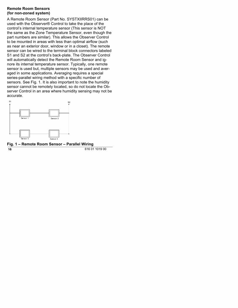
A Remote Room Sensor (Part No. SYSTXIIRRS01) can beused with the Observer® Control to take the place of thecontrol’s internal temperature sensor (This sensor is NOTthe same as the Zone Temperature Sensor, even though thepart numbers are similar). This allows the Observer Controlto be mounted in areas with less than optimal airflow (suchas near an exterior door, window or in a closet). The remotesensor can be wired to the terminal block connectors labeledS1 and S2 at the control’s back-plate. The Observer Controlwill automatically detect the Remote Room Sensor and ig-nore its internal temperature sensor. Typically, one remotesensor is used but, multiple sensors may be used and aver-aged in some applications. Averaging requires a specialseries-parallel wiring method with a specific number ofsensors. See Fig. 1. It is also important to note the humiditysensor cannot be remotely located, so do not locate the Ob-server Control in an area where humidity sensing may not beaccurate.
Fig. 1 – Remote Room Sensor – Parallel Wiring

17616 01 1019 00
Wiring ConsiderationsOrdinary thermostat wire is recommended. Use 22 AWG orlarger for normal wiring applications. Continuous wire lengthsover 100 ft. should use 20 AWG or larger.NOTE: The communicating bus wiring only requires afour-wire connection; however, it is good practice to run ther-mostat cable having more than four wires in the event of adamaged or broken wire during installation.Each communicating device in the system has a four-pinconnector. It is recommended that the following color codebe used when wiring each device:DX+ — Green = Data ADX- — Yellow = Data BC — White = 24VAC (Com)R — Red = 24VAC (Hot)NOTE: TERMINAL MARKINGS FOR EACH COMMUNICAT-ING SYSTEM COMPONENT MAY NOT BE IN THE SAMEORDER. IT IS NOT MANDATORY THAT THE ABOVE COL-OR CODE BE USED, BUT EACH CONNECTOR IN THESYSTEM MUST BE WIRED CONSISTENTLY.A separate four-pin connector comes inside packaging andshould be used when connecting to furnace (or fan coil). En-sure connector is inserted properly into circuit board.1. Turn off all power to equipment.2. If an existing thermostat or control is being replaced:
a. Remove existing thermostat from wall.. . . . . . .b. Disconnect wires from existing thermostat.. . . . . . .c. Discard or recycle old thermostat.. . . . . . .
18 616 01 1019 00
NOTE: Mercury is a hazardous waste, if existing control con-tains any mercury, it MUST be disposed of properly. The Ob-server® Control does not contain mercury.3. Select Observer Control mounting plastic4. Route wires through hole in mounting plastic. Level rearplastic against wall (for aesthetic value only - Observer Con-trol need not be level to operate properly) and mark wallthrough two mounting holes.5. Drill two 3/16-in (4.8 mm) mounting holes in wall wheremarked.6. Secure mounting plastic to wall using two screws and an-chors provided.7. Adjust length and routing of each wire to reach each wireentry on the connector back-plate. Strip 1/4--in (6.4 mm) ofinsulation from each wire.8. Match and connect thermostat wires to proper terminalson wall control back-plate. See Wiring Diagrams inAppendix.9. Push any excess wire into the wall. Seal hole in wall toprevent any air leaks. Leaks can affect operation.10. Attach Observer Control to the mounting plastic by liningup the plastic guides on the back of the control with theopening on the mounting plastic and push on.11. Perform installation of all other system equipment (i.e.humidifier, UV lights, etc.).12. Turn on power to equipment.NOTE: In a dual fuel installation with a non-communicatingheat pump, an OAT sensor must be installed, or the heatpump will not run.

19616 01 1019 00
Shielded Wire
If the thermostat wiring will be located near or in parallel withhigh voltage wiring, cable TV or Ethernet wiring, then shiel-ded thermostat wire can be used to reduce or eliminate po-tential interference. The shield wire should be connected tothe C terminal, or ground, at the indoor unit. The shield wireshould NOT be connected to any terminal at the wall control.Connecting the shield to ground at both ends can cause cur-rent loops in the shield, reducing shield effectiveness.Non-communicating equipment
The Observer® Control, when paired with theNAXA00101DB daughter board, will operate non-communic-ating equipment. When the system utilizes theNAXA00101DB daughter board, the Observer Control oper-ates as a standard universal thermostat. See Appendix Wir-ing Diagrams
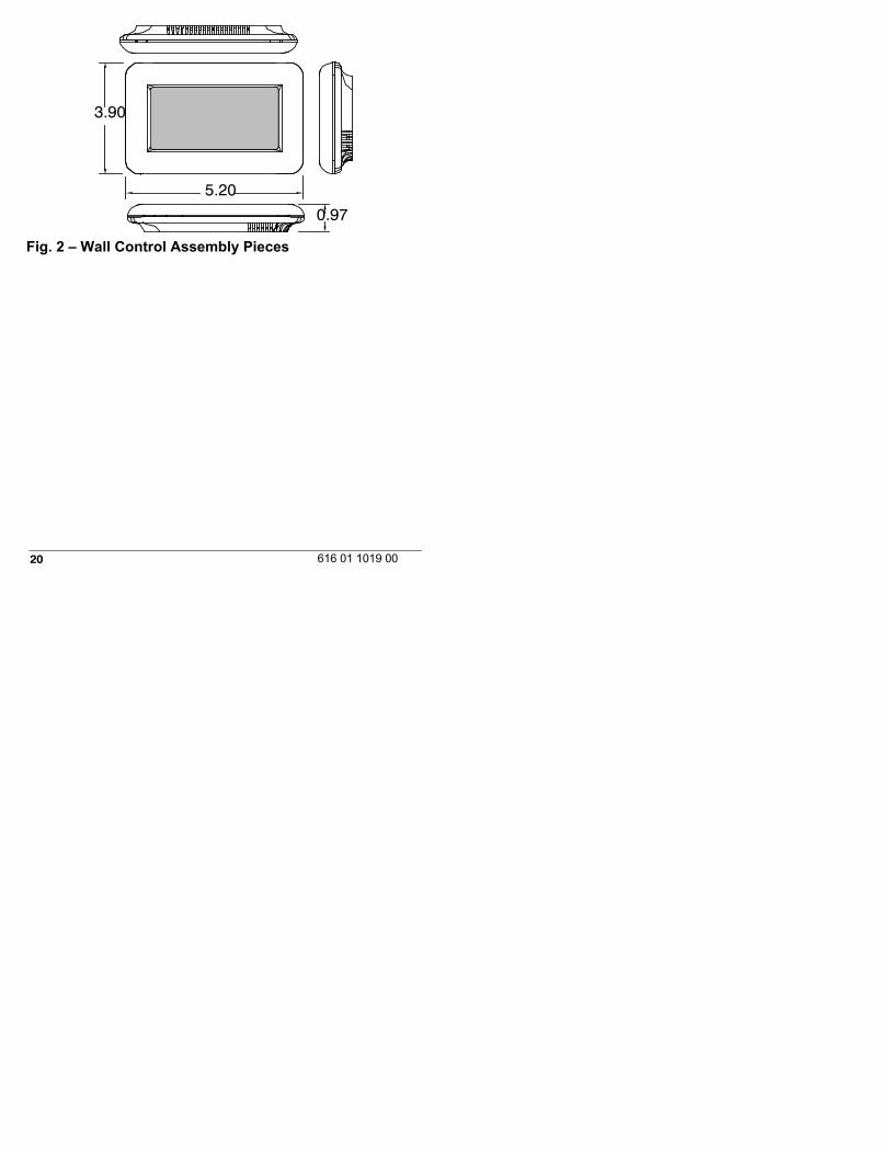
MountingFirst become familiar with all plastic assembly pieces shownin Figure 2. The wall control will snap together with theback-plate. A back-plate is supplied Figure 2. Attachback-plate using only a small hole in the wall allowing a fourwire connection to pass through. Mount the assembly to theback-plate.NOTE: Once Observer Control is secured to wall with theback-plate assembly (snapped together), care must be takennot to bend or break the interlocking tabs when removing.
20 616 01 1019 00
3.90
5.20
0.97
Fig. 2 – Wall Control Assembly Pieces
21616 01 1019 00
Humidifier ConnectionA 24VAC bypass or fan powered humidifier may be installed.NOTE: Do Not Use a traditional humidistat to control humidi-fier operation. If a humidifier is installed, let the Observer®Control operate humidifier.Bypass Humidifiers
A bypass humidifier is normally wired directly to the furnaceor fan coil HUM and 24VAC COM terminals. The Observer®Control will automatically energize the HUM output during acall for humidification. See the humidifier installation instruc-tions for the proper wiring procedure for each particular hu-midifier.Fan Powered Humidifiers
Most fan powered humidifiers produce internal 24VAC in or-der to energize upon a switch or contact closure. For thisapplication, a 24VAC N.O. Isolation Relay (DPST) MUST beused to prevent mixing the internal humidifier power with theindoor equipment transformer. Applying 24VAC isolation re-lay coil to furnace or fan coil HUM and COM terminals willallow the Observer® Control to automatically energize theHUM output during a call for humidification. The N.O. relaycontacts will be used to energize the humidifier. See fanpowered humidifier installation instructions for more details.
22 616 01 1019 00
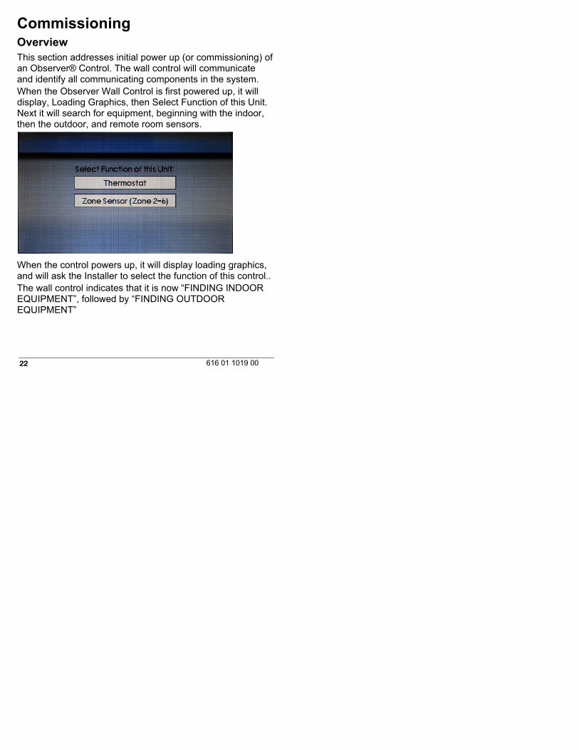
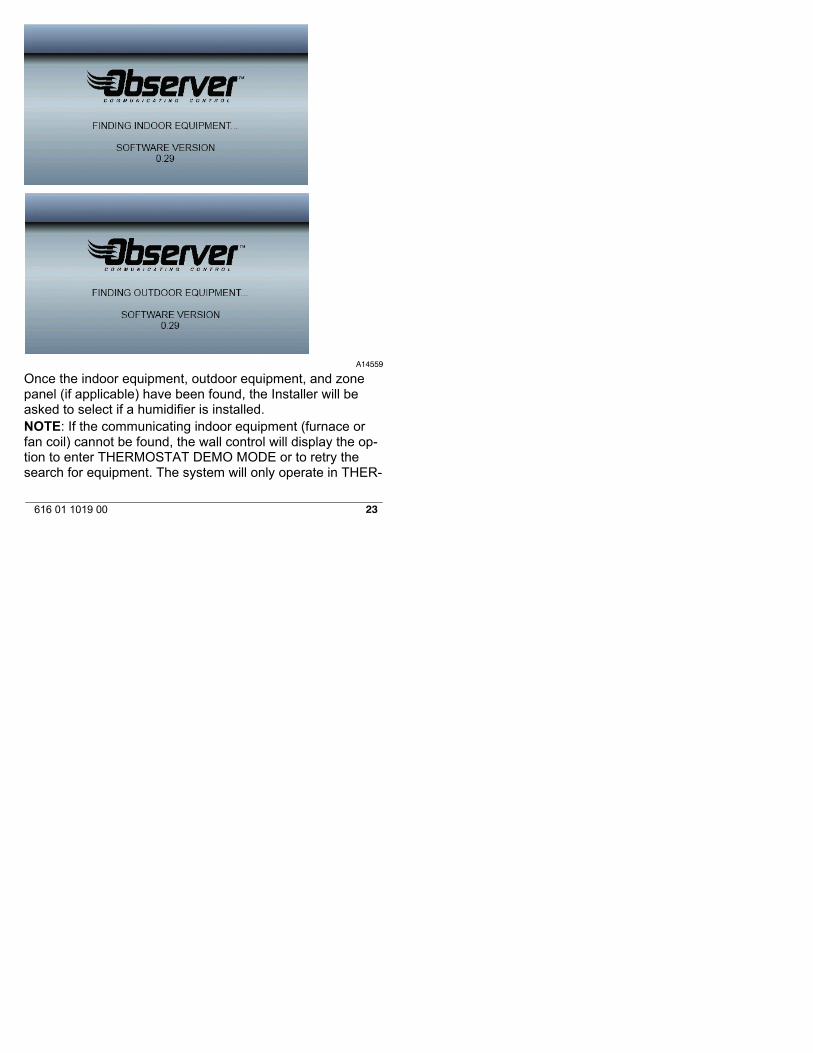
CommissioningOverviewThis section addresses initial power up (or commissioning) ofan Observer® Control. The wall control will communicateand identify all communicating components in the system.When the Observer Wall Control is first powered up, it willdisplay, Loading Graphics, then Select Function of this Unit.Next it will search for equipment, beginning with the indoor,then the outdoor, and remote room sensors.
When the control powers up, it will display loading graphics,and will ask the Installer to select the function of this control..The wall control indicates that it is now “FINDING INDOOREQUIPMENT”, followed by “FINDING OUTDOOREQUIPMENT”
23616 01 1019 00
A14559
Once the indoor equipment, outdoor equipment, and zonepanel (if applicable) have been found, the Installer will beasked to select if a humidifier is installed.NOTE: If the communicating indoor equipment (furnace orfan coil) cannot be found, the wall control will display the op-tion to enter THERMOSTAT DEMO MODE or to retry thesearch for equipment. The system will only operate in THER-
24 616 01 1019 00
MOSTAT DEMO MODE if no communicating equipment isfound.If a communicating indoor unit is found, but a communicatingoutdoor unit or relay board is not found, the installer will beprompted to select the outdoor type; either AC, Heat Pump,or NONE.
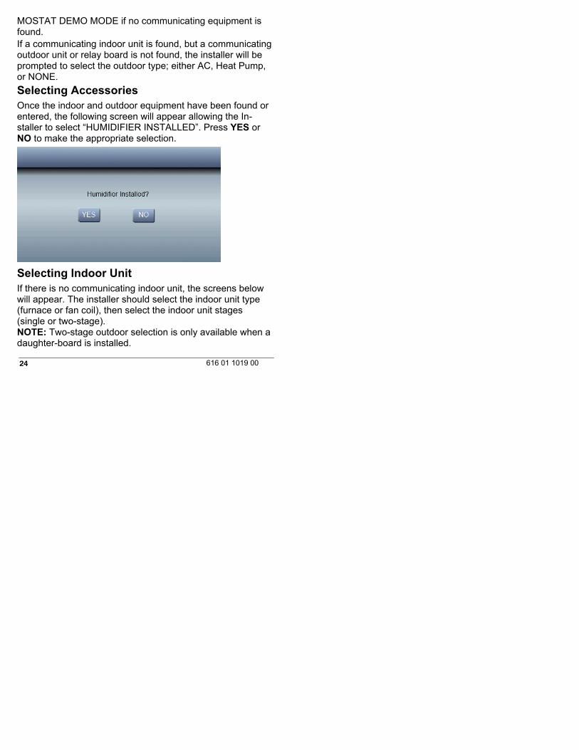
Selecting AccessoriesOnce the indoor and outdoor equipment have been found orentered, the following screen will appear allowing the In-staller to select “HUMIDIFIER INSTALLED”. Press YES orNO to make the appropriate selection.
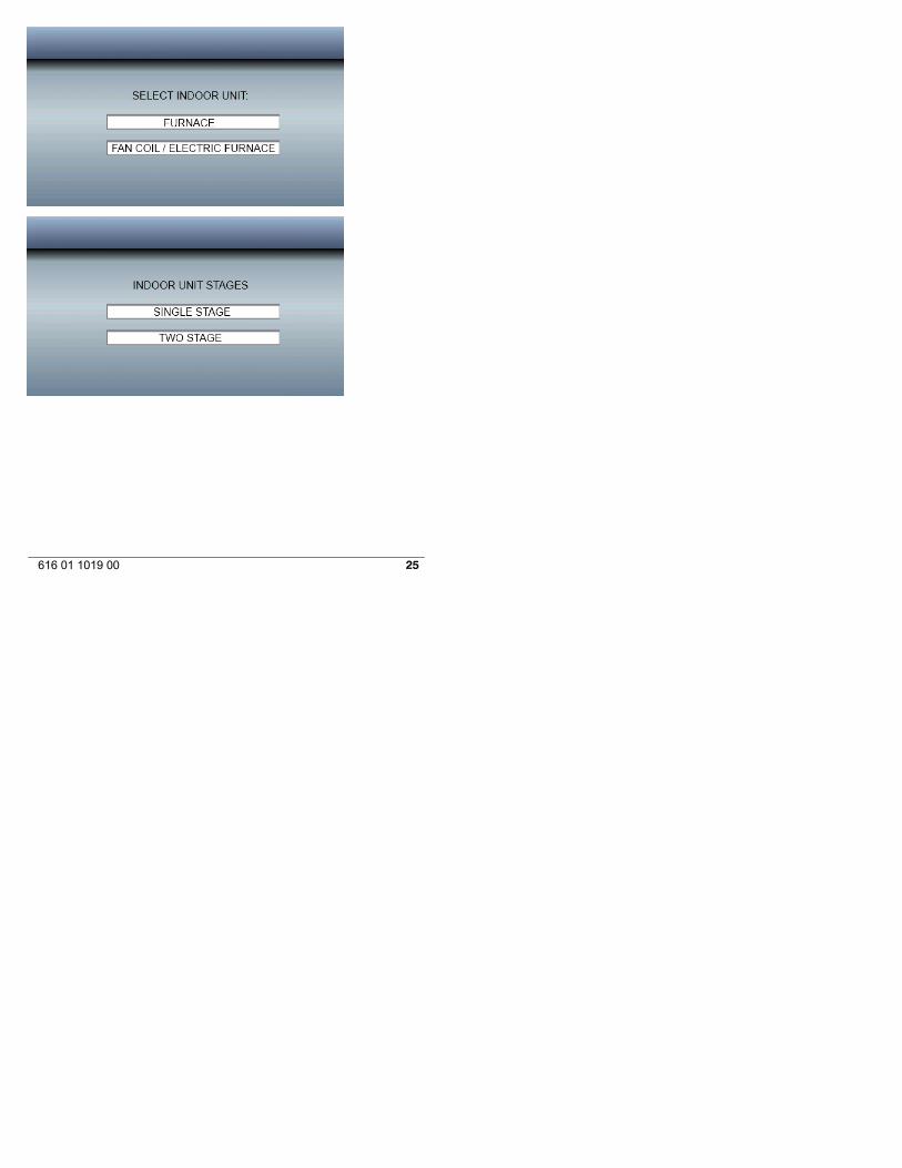
Selecting Indoor UnitIf there is no communicating indoor unit, the screens belowwill appear. The installer should select the indoor unit type(furnace or fan coil), then select the indoor unit stages(single or two-stage).NOTE: Two-stage outdoor selection is only available when adaughter-board is installed.
25616 01 1019 00
26 616 01 1019 00
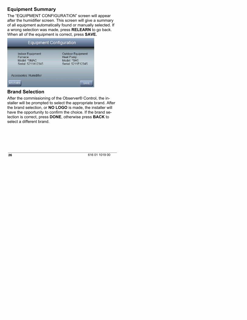
Equipment SummaryThe “EQUIPMENT CONFIGURATION” screen will appearafter the humidifier screen. This screen will give a summaryof all equipment automatically found or manually selected. Ifa wrong selection was made, press RELEARN to go back.When all of the equipment is correct, press SAVE.
Brand SelectionAfter the commissioning of the Observer® Control, the in-staller will be prompted to select the appropriate brand. Afterthe brand selection, or NO LOGO is made, the installer willhave the opportunity to confirm the choice. If the brand se-lection is correct, press DONE, otherwise press BACK toselect a different brand.
27616 01 1019 00
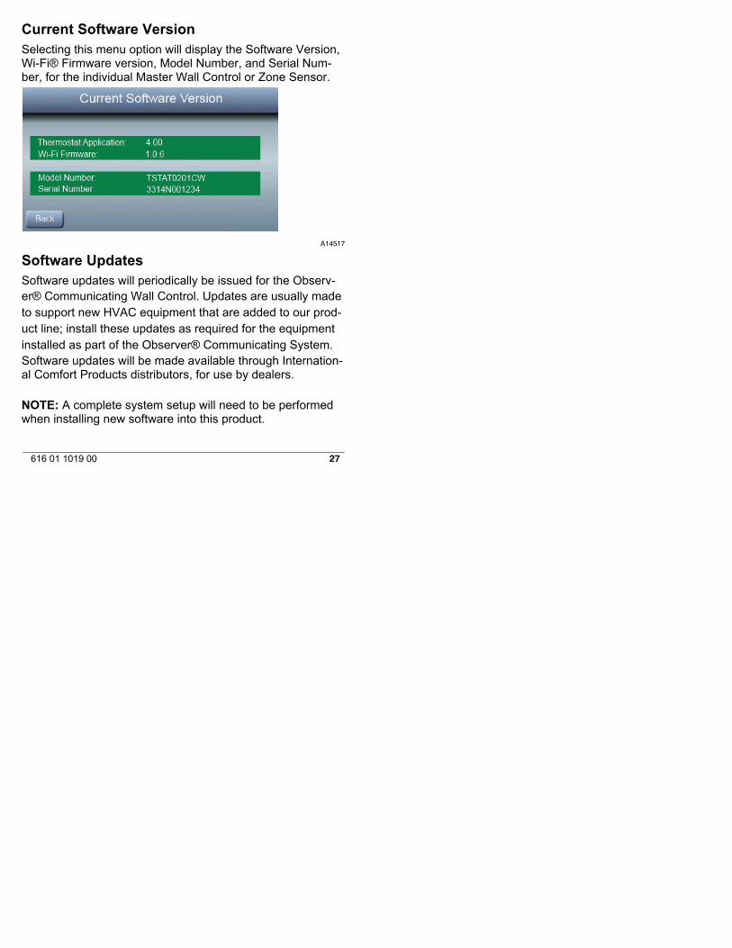
Current Software VersionSelecting this menu option will display the Software Version,Wi-Fi® Firmware version, Model Number, and Serial Num-ber, for the individual Master Wall Control or Zone Sensor.
A14517
Software UpdatesSoftware updates will periodically be issued for the Observ-er® Communicating Wall Control. Updates are usually madeto support new HVAC equipment that are added to our prod-uct line; install these updates as required for the equipmentinstalled as part of the Observer® Communicating System.Software updates will be made available through Internation-al Comfort Products distributors, for use by dealers.
NOTE: A complete system setup will need to be performedwhen installing new software into this product.
28 616 01 1019 00
Setting Up Remote Access and Wi-Fi®ConnectionThe Observer® Communicating Wall Control can connectthrough an in-home Wi-Fi® network to connect to the Inter-net. If the in-home Wi-Fi network or router is found to be in-compatible with the Observer wall control, an accessory Ob-server Wireless Access Point (NAXA00101WA) or any othercompatible wireless router can be installed to establish Wi-Ficonnectivity. Wi-Fi range extenders may also be used if thewall control is located a significant distance away from theWi-Fi access point or router. More information may be foundat the www.MyObserverComfort.com website.Please contact your distributor, or call the help desk (avail-able 8:00 AM - 5:00 PM ET, M-F) at 877-591-8908, if youneed help with Wi-Fi set-up and connection to the MyOb-serverComfort web server.See the Owner’s Manual for complete instructions oncommissioning the Wi-Fi® connection.Connect the blue WAN port of the optional NAXA00101WAaccessory (TP-LINK®) Wireless Access Point to the home-owner’s existing router LAN port using the provided Ethernetcable. The LAN ports on the back of the TP-LINK WirelessAccess Point should not be used for other devices. The TP-LINK Wireless Access Point should only be used for connec-tion of the ObserverR wall control, and is not intended to beused wired or wirelessly with any other devices. Connect theprovided antenna and apply power to the wireless accesspoint using the provided power supply.
29616 01 1019 00
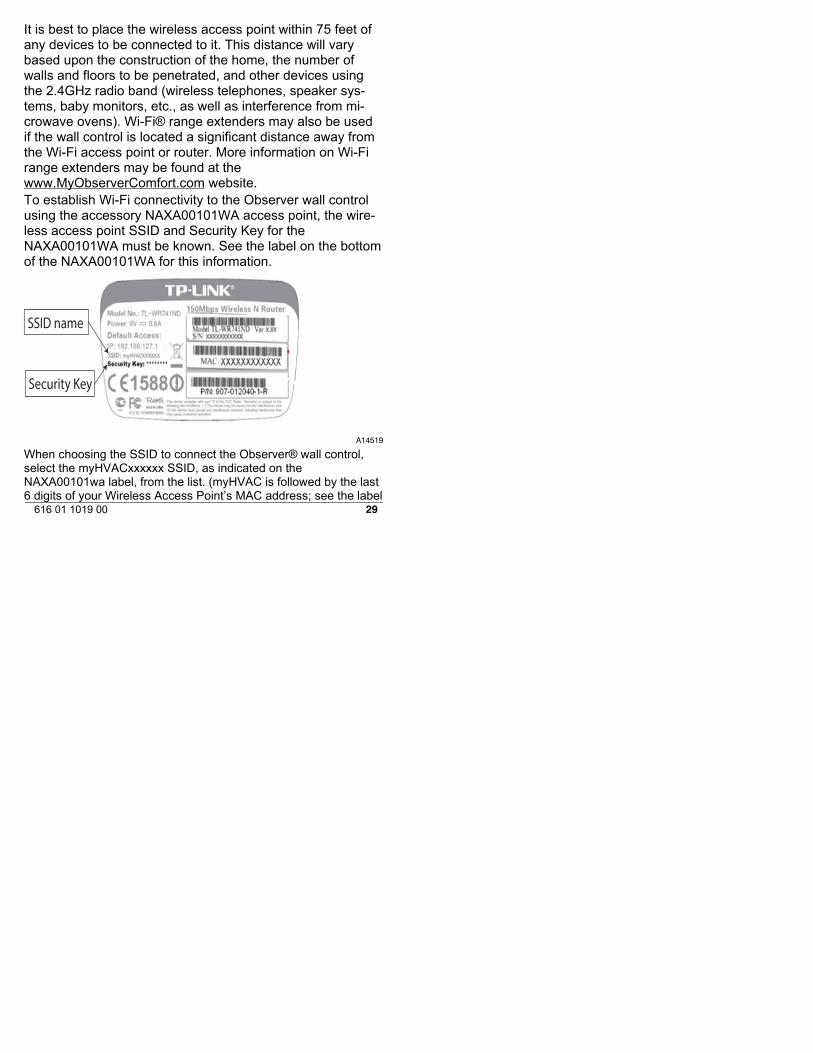
It is best to place the wireless access point within 75 feet ofany devices to be connected to it. This distance will varybased upon the construction of the home, the number ofwalls and floors to be penetrated, and other devices usingthe 2.4GHz radio band (wireless telephones, speaker sys-tems, baby monitors, etc., as well as interference from mi-crowave ovens). Wi-Fi® range extenders may also be usedif the wall control is located a significant distance away fromthe Wi-Fi access point or router. More information on Wi-Firange extenders may be found at thewww.MyObserverComfort.com website.To establish Wi-Fi connectivity to the Observer wall controlusing the accessory NAXA00101WA access point, the wire-less access point SSID and Security Key for theNAXA00101WA must be known. See the label on the bottomof the NAXA00101WA for this information.
SSID name
Security Key
A14519
When choosing the SSID to connect the Observer® wall control,select the myHVACxxxxxx SSID, as indicated on theNAXA00101wa label, from the list. (myHVAC is followed by the last6 digits of your Wireless Access Point’s MAC address; see the label

30 616 01 1019 00
on the bottom of the TP-LINK® wireless access point). You mayhave to use the arrow at the bottom right of the SSID display screento scroll to the next screen to find “myHVACxxxxxx”.
A14518
Install/Service Menus –Communicating andNon-Communicating ModeThe “INSTALLER CONFIGURATION” menus contain vitalinformation. This information enables the Installer or Serviceperson to view a summary of what has been installed, etc.This information is not covered in the Owner’s Manual.To enter INSTALLER CONFIGURATION menus, press andhold the FAN BUTTON for at least ten seconds. The follow-ing menu will appear: (If an item is grayed out, that item isnot applicable to the equipment configuration selected – forexample, reversing valve will be grayed out if a standard ACsystem is selected).

31616 01 1019 00
NOTE: The INSTALL / SERVICE menu will automaticallyexit after 90 seconds of no activity.Equipment Summary MenuThis screen shows indoor unit type and model number, out-door unit type (and model number if a communicating out-door unit), and any accessories that are installed are recog-nized.
32 616 01 1019 00
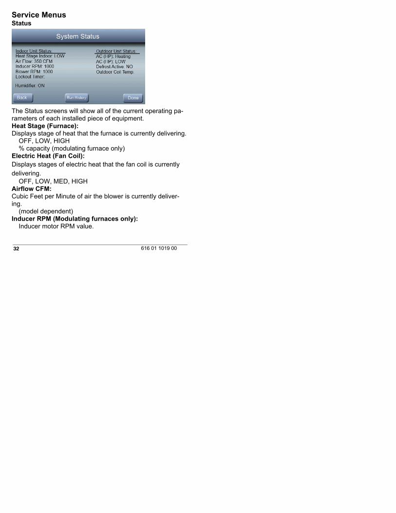
Service MenusStatus
The Status screens will show all of the current operating pa-rameters of each installed piece of equipment.Heat Stage (Furnace):Displays stage of heat that the furnace is currently delivering.
OFF, LOW, HIGH% capacity (modulating furnace only)
Electric Heat (Fan Coil):Displays stages of electric heat that the fan coil is currentlydelivering.
OFF, LOW, MED, HIGHAirflow CFM:Cubic Feet per Minute of air the blower is currently deliver-ing.
(model dependent)Inducer RPM (Modulating furnaces only):
Inducer motor RPM value.
33616 01 1019 00
Blower RPM (Modulating furnaces only):Actual RPM feedback from indoor blower motor.
Lockout Timer:If a lockout timer is active, this will show the current time val-ue. See equipment manual for details on lockout timers.
SecondsHeat Pump/AC StatusStage: (Heat/Cool):Displays stage of heating or cooling that the Heat Pump/ACis delivering.
OFF, HIGH, LOWDefrost:
NO, YESOutdoor Coil Temp:Temperature of the outdoor unit coil (only available on2-stage communicating outdoor units).
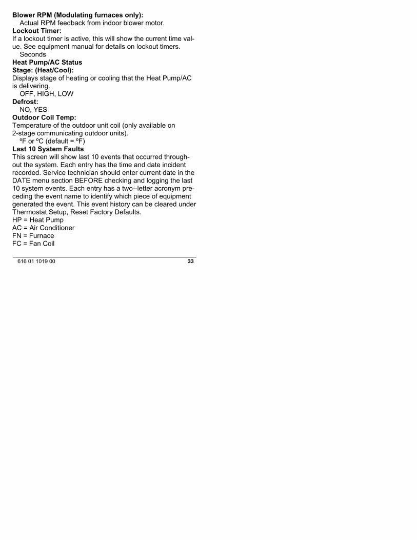
ºF or ºC (default = ºF)Last 10 System FaultsThis screen will show last 10 events that occurred through-out the system. Each entry has the time and date incidentrecorded. Service technician should enter current date in theDATE menu section BEFORE checking and logging the last10 system events. Each entry has a two--letter acronym pre-ceding the event name to identify which piece of equipmentgenerated the event. This event history can be cleared underThermostat Setup, Reset Factory Defaults.HP = Heat PumpAC = Air ConditionerFN = FurnaceFC = Fan Coil
34 616 01 1019 00
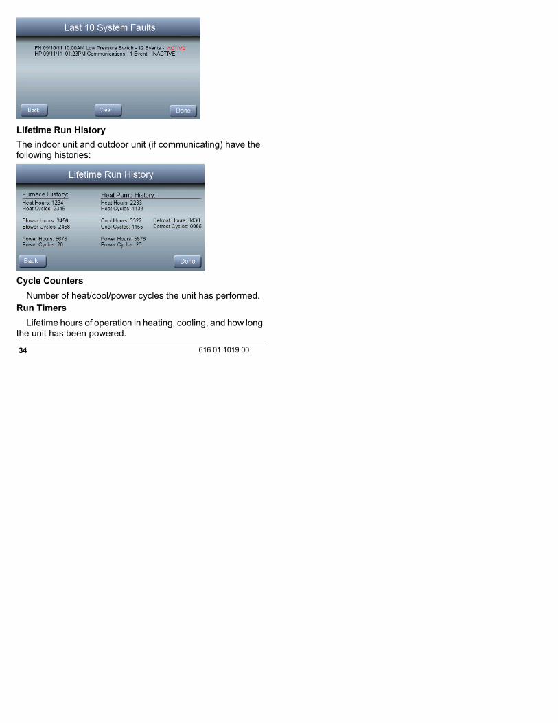
Lifetime Run History
The indoor unit and outdoor unit (if communicating) have thefollowing histories:
Cycle Counters
Number of heat/cool/power cycles the unit has performed.Run Timers
Lifetime hours of operation in heating, cooling, and how longthe unit has been powered.
35616 01 1019 00
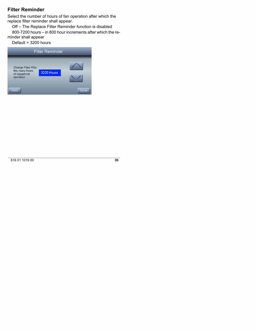
Filter ReminderSelect the number of hours of fan operation after which thereplace filter reminder shall appear.
Off – The Replace Filter Reminder function is disabled800-7200 hours – in 800 hour increments after which the re-
minder shall appearDefault = 3200 hours
36 616 01 1019 00
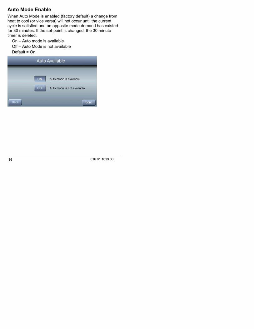
Auto Mode EnableWhen Auto Mode is enabled (factory default) a change fromheat to cool (or vice versa) will not occur until the currentcycle is satisfied and an opposite mode demand has existedfor 30 minutes. If the set-point is changed, the 30 minutetimer is deleted.
On – Auto mode is availableOff – Auto Mode is not availableDefault = On.
37616 01 1019 00
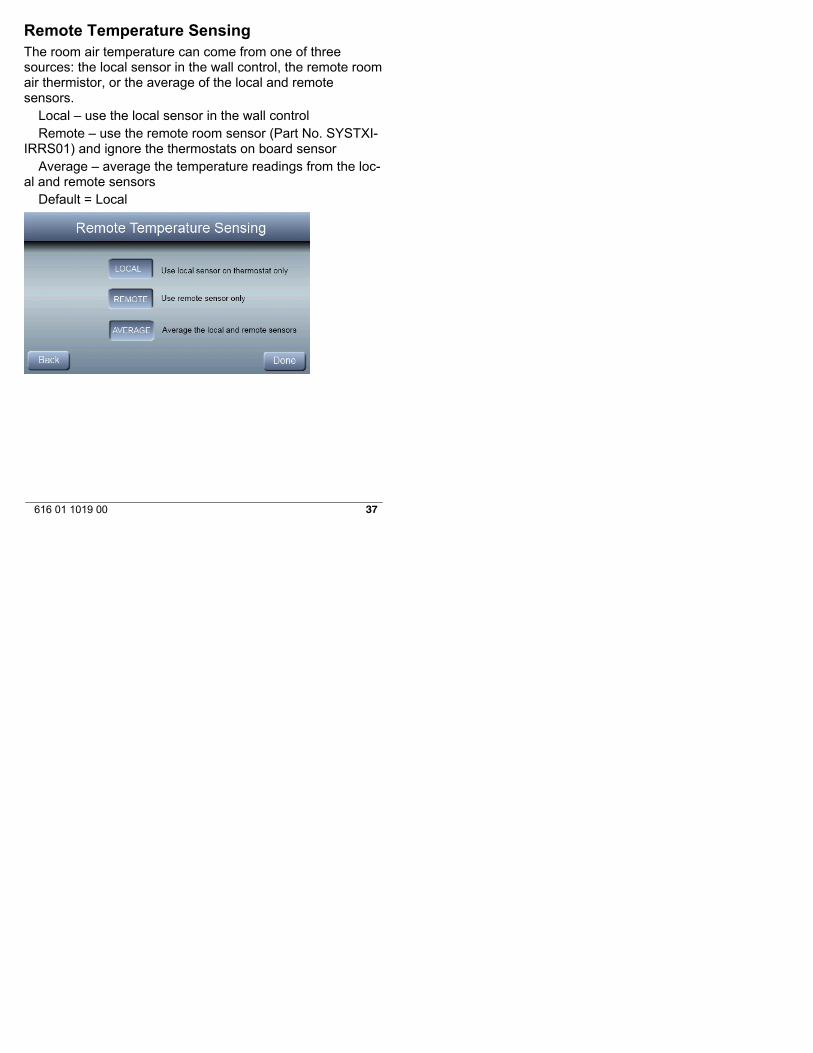
Remote Temperature SensingThe room air temperature can come from one of threesources: the local sensor in the wall control, the remote roomair thermistor, or the average of the local and remotesensors.
Local – use the local sensor in the wall controlRemote – use the remote room sensor (Part No. SYSTXI-
IRRS01) and ignore the thermostats on board sensorAverage – average the temperature readings from the loc-
al and remote sensorsDefault = Local

38 616 01 1019 00
Reversing ValveFor heat pump applications, the reversing valve will be activewith heating or cooling operation.
HeatCool (default)
39616 01 1019 00
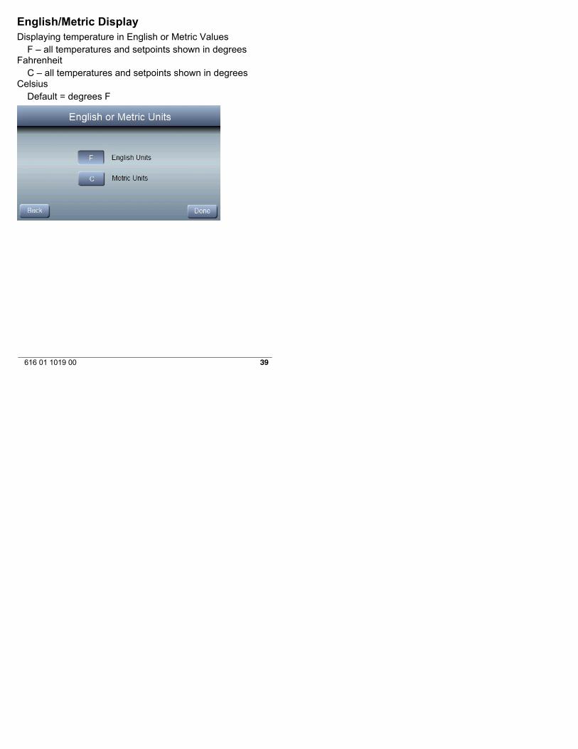
English/Metric DisplayDisplaying temperature in English or Metric Values
F – all temperatures and setpoints shown in degreesFahrenheit
C – all temperatures and setpoints shown in degreesCelsius
Default = degrees F

40 616 01 1019 00
Fan on with W
An option to turn the fan on with a call for heating
ONOFF (default)

41616 01 1019 00
Cooling LockoutWhen enabled, cooling will not be provided when the outsidetemperature is below 55º F.
Off – Cooling is allowed at all outdoor air temperaturesOn – Cooling not allowed when outdoor air temperature is
below 55º F.Default = Off
42 616 01 1019 00
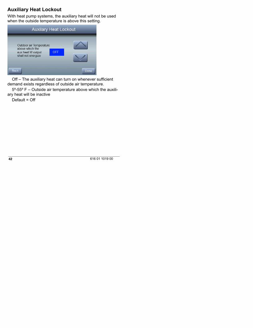
Auxiliary Heat LockoutWith heat pump systems, the auxiliary heat will not be usedwhen the outside temperature is above this setting.
Off – The auxiliary heat can turn on whenever sufficientdemand exists regardless of outside air temperature.
5º-55º F – Outside air temperature above which the auxili-ary heat will be inactive
Default = Off
43616 01 1019 00
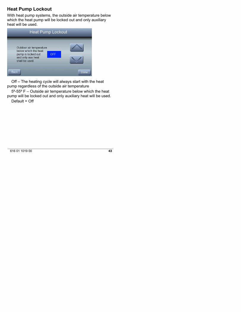
Heat Pump LockoutWith heat pump systems, the outside air temperature belowwhich the heat pump will be locked out and only auxiliaryheat will be used.
Off – The heating cycle will always start with the heatpump regardless of the outside air temperature
5º-55º F – Outside air temperature below which the heatpump will be locked out and only auxiliary heat will be used.
Default = Off
44 616 01 1019 00
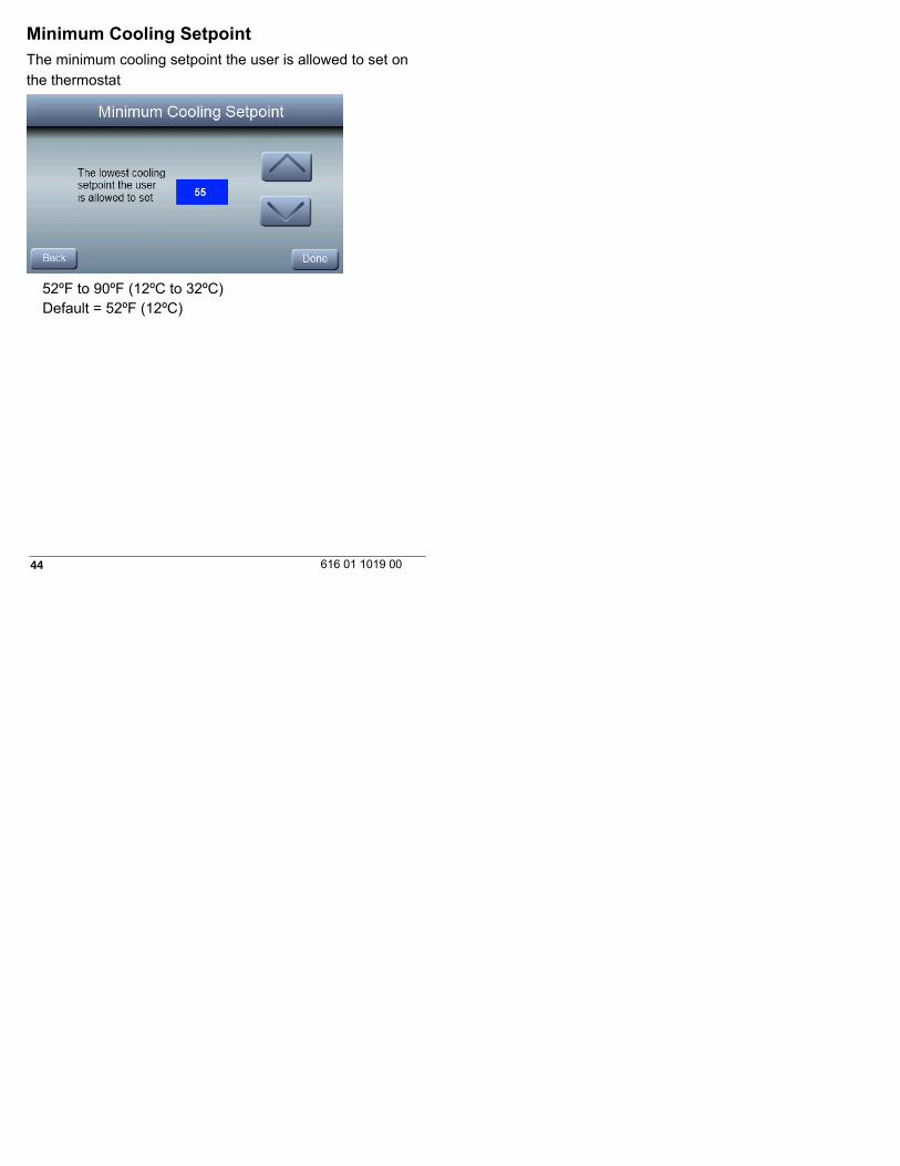
Minimum Cooling Setpoint
The minimum cooling setpoint the user is allowed to set on
the thermostat
52ºF to 90ºF (12ºC to 32ºC)Default = 52ºF (12ºC)

45616 01 1019 00
Maximum Heating Setpoint
The maximum heating setpoint the user is allowed to set on
the thermostat
50ºF to 88ºF (10ºC to 30ºC)Default = 88ºF (30ºC)

46 616 01 1019 00
Outdoor Air Temperature OffsetThis option allows calibration (or deliberate mis-calibration)of the outdoor temperature. This offset is added to the actualtemperature values.
-5ºF to +5ºF (-3ºC to +3ºC) – Number of degrees added tothe actual temperature value
Default = 0

47616 01 1019 00
Room Air Temperature Offset
-5ºF to +5ºF (-3ºC to +3ºC) – Number of degrees added tothe actual temperature value
Default = 0
48 616 01 1019 00
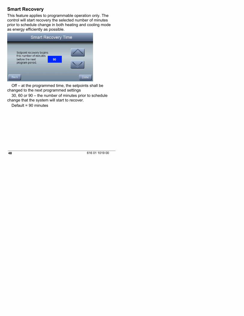
Smart RecoveryThis feature applies to programmable operation only. Thecontrol will start recovery the selected number of minutesprior to schedule change in both heating and cooling modeas energy efficiently as possible.
Off – at the programmed time, the setpoints shall bechanged to the next programmed settings
30, 60 or 90 – the number of minutes prior to schedulechange that the system will start to recover.
Default = 90 minutes
49616 01 1019 00
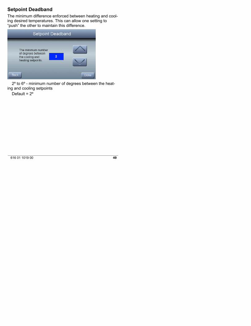
Setpoint DeadbandThe minimum difference enforced between heating and cool-ing desired temperatures. This can allow one setting to“push” the other to maintain this difference.
2º to 6º - minimum number of degrees between the heat-ing and cooling setpoints
Default = 2º
50 616 01 1019 00
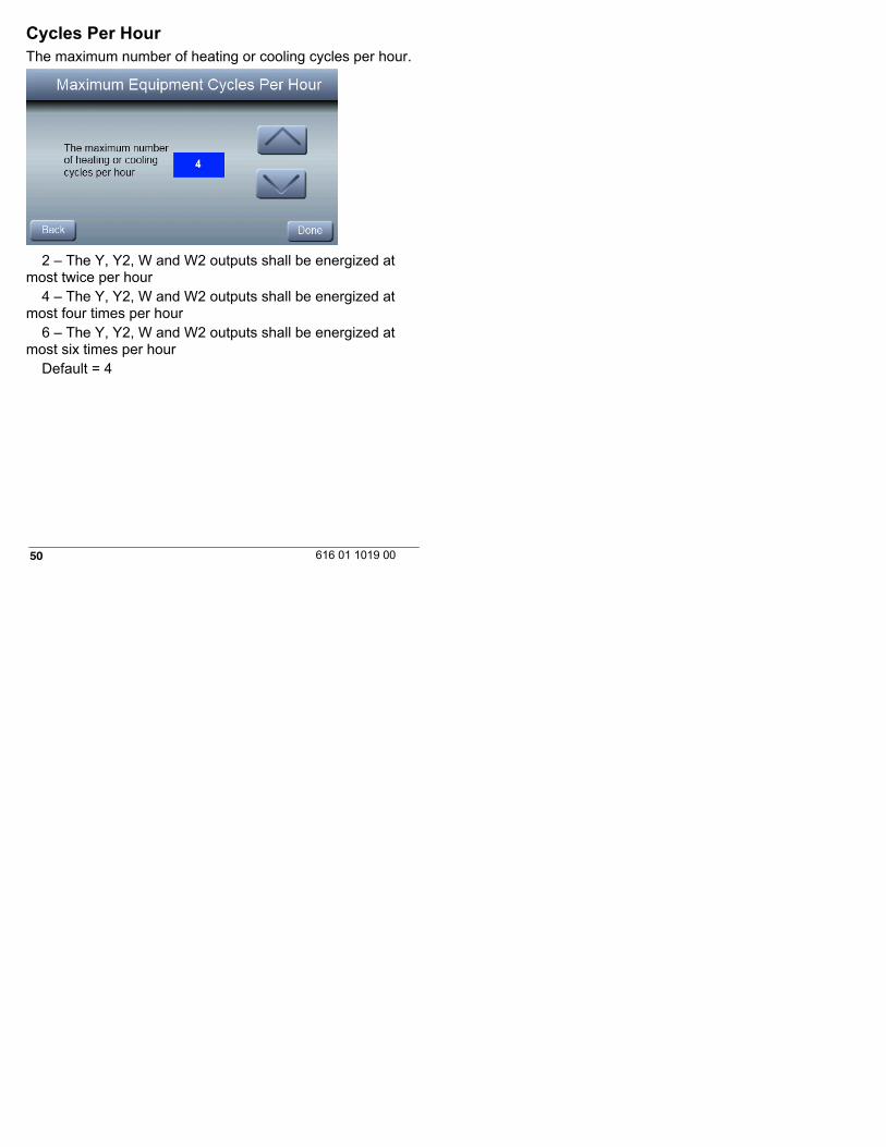
Cycles Per HourThe maximum number of heating or cooling cycles per hour.
2 – The Y, Y2, W and W2 outputs shall be energized atmost twice per hour
4 – The Y, Y2, W and W2 outputs shall be energized atmost four times per hour
6 – The Y, Y2, W and W2 outputs shall be energized atmost six times per hour
Default = 4

51616 01 1019 00
Auto Changeover TimerThis feature designates the minimum number of minutesbetween heating and cooling operation when in auto mode.
5 to 30 minutes (5 minute increments)Default = 30 minutes

52 616 01 1019 00
Time Between Fuel TypesThe minimum amount of time the Y1 and Y2 output must beenergized in heating before turning on the W1 output.
10 to 25 minutes (5 minute increments)Default = 15 minutes
53616 01 1019 00
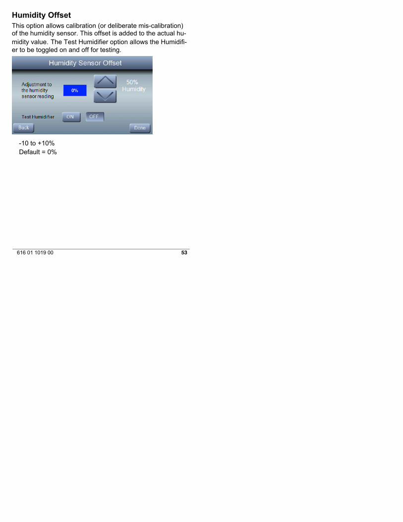
Humidity OffsetThis option allows calibration (or deliberate mis-calibration)of the humidity sensor. This offset is added to the actual hu-midity value. The Test Humidifier option allows the Humidifi-er to be toggled on and off for testing.
-10 to +10%Default = 0%
54 616 01 1019 00
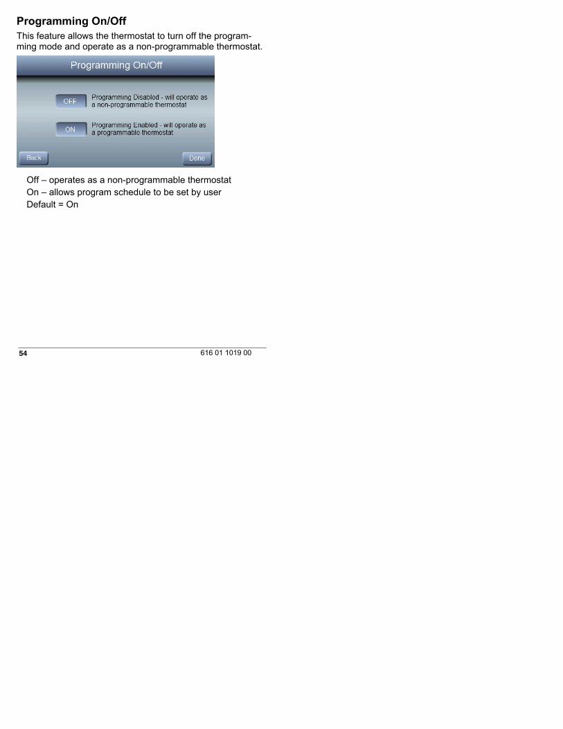
Programming On/OffThis feature allows the thermostat to turn off the program-ming mode and operate as a non-programmable thermostat.
Off – operates as a non-programmable thermostatOn – allows program schedule to be set by userDefault = On

55616 01 1019 00
Reset to Factory DefaultsThis feature allows the installer to return the thermostat to itsfactory default settings. The installer will need to hold the ▼button down for 10 seconds to reset settings.
56 616 01 1019 00
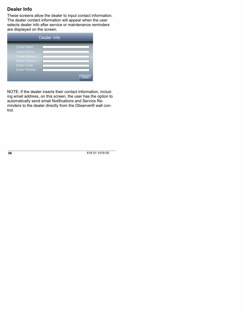
Dealer InfoThese screens allow the dealer to input contact information.The dealer contact information will appear when the userselects dealer info after service or maintenance remindersare displayed on the screen.
NOTE: If the dealer inserts their contact information, includ-ing email address, on this screen, the user has the option toautomatically send email Notifications and Service Re-minders to the dealer directly from the Observer® wall con-trol.
57616 01 1019 00
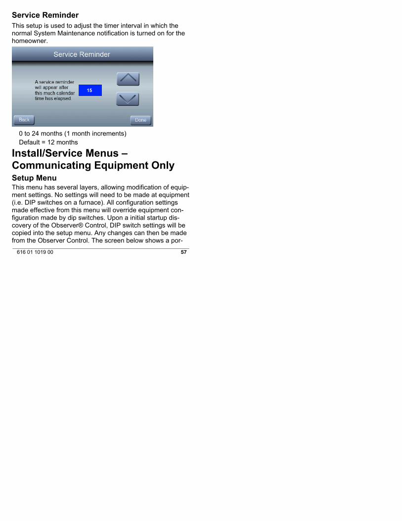
Service ReminderThis setup is used to adjust the timer interval in which thenormal System Maintenance notification is turned on for thehomeowner.
0 to 24 months (1 month increments)Default = 12 months
Install/Service Menus –Communicating Equipment OnlySetup MenuThis menu has several layers, allowing modification of equip-ment settings. No settings will need to be made at equipment(i.e. DIP switches on a furnace). All configuration settingsmade effective from this menu will override equipment con-figuration made by dip switches. Upon a initial startup dis-covery of the Observer® Control, DIP switch settings will becopied into the setup menu. Any changes can then be madefrom the Observer Control. The screen below shows a por-
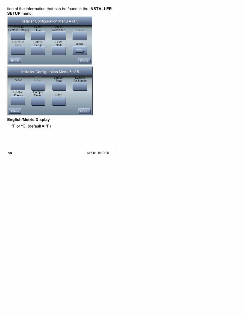
58 616 01 1019 00
tion of the information that can be found in the INSTALLERSETUP menu.
English/Metric Display
ºF or ºC, (default = ºF)

59616 01 1019 00
AirflowUpon a first time start-up of the Observer® Control, the fur-nace DIP switch settings will be copied to the furnace setupmenu. Any changes can then be made from the ObserverControl.Heating Airflow
Furnace / Fancoil Heating Airflow
Selects the airflow of the indoor unit when heating. EFFI-CIENCY is the airflow used to meet specified ratings, COM-FORT is a decreased airflow used to increase the output airtemperature and provide increased comfort.
COMFORT (default)EFFICIENCYMIN CFM (modulating furnace only) – runs the modulating
furnace at the minimum CFMMAX CFM modulating furnace only) – runs the modulating
furnace at the maximum CFM
60 616 01 1019 00
Heat Pump Heating Airflow
COMFORT (default) -- Heat Pump airflow is varied depend-ing on outdoor temperature to maximize comfort.
EFF 325 -- Fixed airflow used to achieve specified ratings.This is nominally 325 CFM/ton, but will vary if a 2--stage out-door unit is used.
EFF 350 -- Fixed airflow used to achieve specified ratings.This is nominally 350 CFM/ton, but will vary if a 2--stage out-door unit is used.
MAXIMUM -- 400 CFM/ton.Cooling Airflow
COMFORT (default) -- cooling airflow is varied depending onhumidity and temperature demands settings. This selection en-ables the full dehumidify and comfort capabilities of the system.When COMFORT is not selected, the unit will not run reducedairflows for dehumidification.
EFF 325 -- fixed airflow used to achieve specified ratings –no dehumidification airflow reduction. This is nominally 325CFM/ton, but will vary if a 2--stage outdoor unit is used.
EFF 350 -- fixed airflow used to achieve specified ratings –no dehumidification airflow reduction. This is nominally 350CFM/ton, but will vary if a 2--stage outdoor unit is used.
MAXIMUM -- 400 CFM/ton. No dehumidification airflow re-duction.Dehum Airflow
NORMAL (default) -- When equipment is running to dehu-midify, the airflow is allowed to adjust to a minimum to satisfythe dehumidification call.

61616 01 1019 00
HIGH -- Minimum airflow during the dehumidify mode is in-creased to reduce duct and register sweating.Furnace Airflow (Capacity) Limiting
The following settings allow the installer to restrict the fur-nace within certain minimum and maximum airflows. Theseairflows are converted to capacities. The Min and Max limitsare determined by the equipment size.Min CFM (only appears with modulating furnaces)Minimum CFM to run a modulating furnace. This will in-crease the minimum operating capacity of the furnace. De-fault value is the furnace air flow for the lowest heat capacity.Maximum CFM (only appears with modulating furnaces)Maximum CFM to run a modulating furnace. This will reducethe operating capacity of the furnace. Default value is thefurnace air flow for the highest heat capacity.Dehum Drain
Turns off the continuous fan at the end of cooling cycle for fiveminutes in order to drain the indoor coil of water. The fan will onlybe turned off if a dehumidify demand existed at the start of or duringthe cooling cycle. Default is enabled.
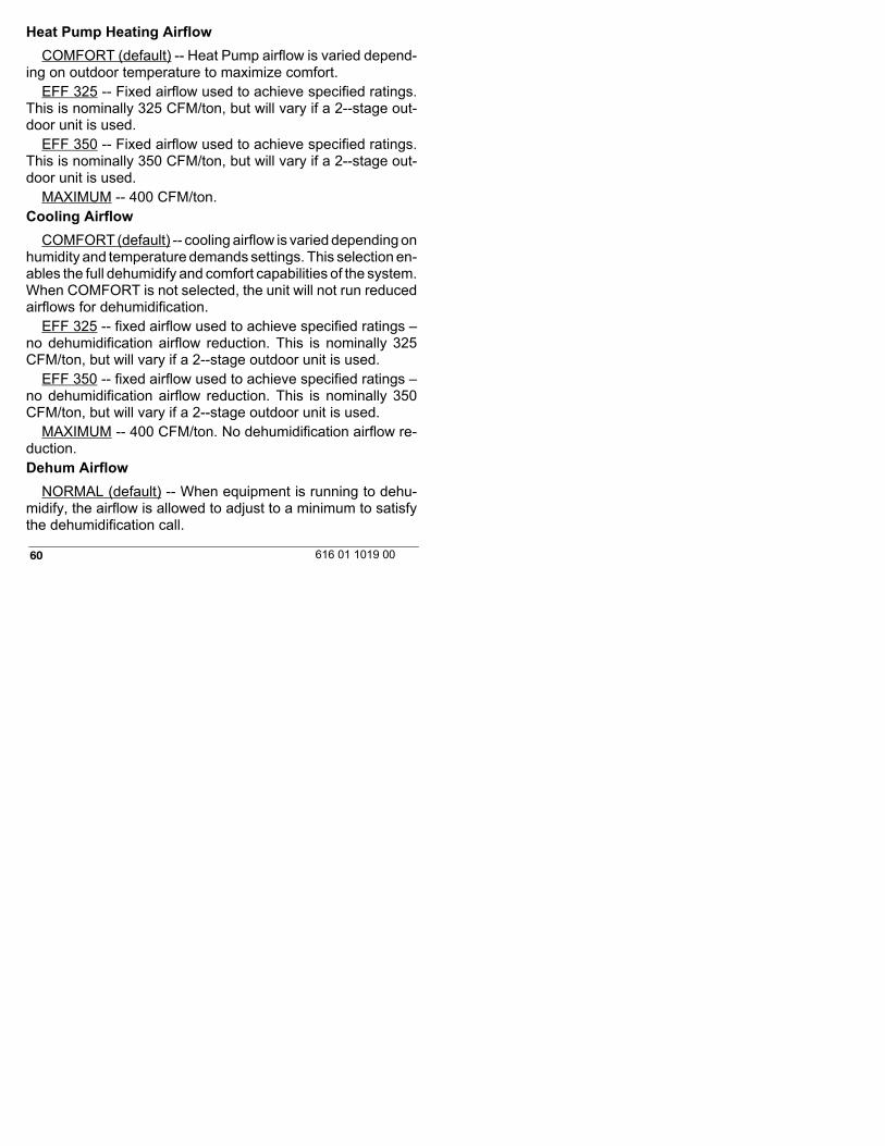
Off Delay
Amount of time the blower will continue to run after heatinghas shut off.
90 seconds120 seconds (default)150 seconds180 seconds
62 616 01 1019 00
Low Heat Rise
Set to ON if the system contains a bypass humidifier. TheON setting will increase the furnace low heat airflow.
OnOff (default)
63616 01 1019 00
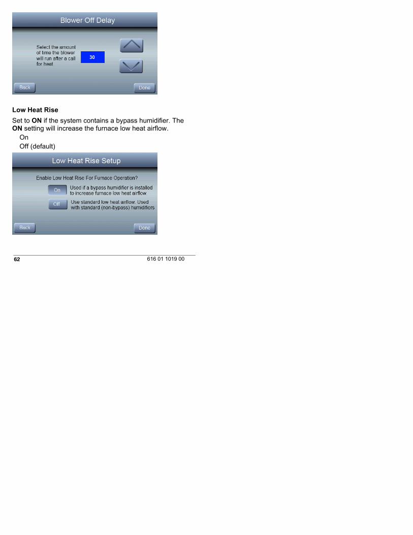
Defrost Interval
Time interval at which defrost cycles can occur on a heatpump.
30 minutes60 minutes90 minutes120 minutes (default)Auto-Defrost interval optimized by outdoor control (default
for communicating HP)

64 616 01 1019 00
Defrost With FurnaceChoose whether furnace operates during defrost cycle.
YES (default)NO
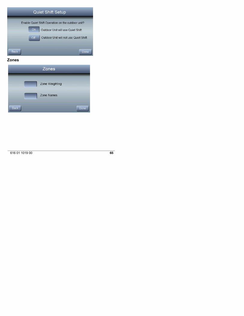
Quiet Shift
Turns on Quiet Shift function in 1-stage or 2-stage commu-nicating heat pumps.
OFF (default)ON
65616 01 1019 00
Zones

66 616 01 1019 00
Zone Weighting
This configuration allows the installer to select the “size” ofeach zone. Typically, living areas are assigned a largerweight %, or importance factor, than bedrooms and smallerareas. The Zone weight affects what heating and coolingstages are used to condition the calling zones. If only onezone is calling for conditioning and that zones has a lowweight, only low stage may be used. Example: if a zoneweighted a 30% is calling for conditioning, the system maynot run until more zones are calling.
67616 01 1019 00
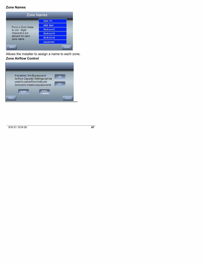
Zone Names
Allows the installer to assign a name to each zone.Zone Airflow Control
Zone airflow control
68 616 01 1019 00
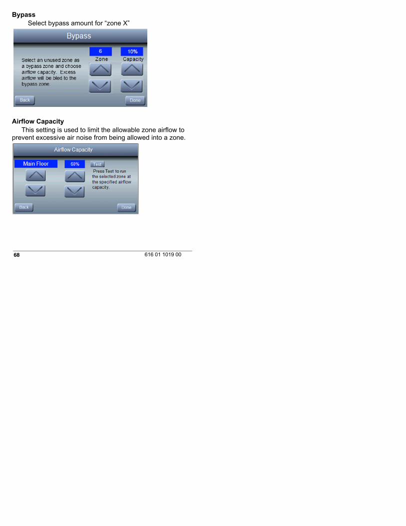
BypassSelect bypass amount for “zone X”
Airflow CapacityThis setting is used to limit the allowable zone airflow to
prevent excessive air noise from being allowed into a zone.
69616 01 1019 00
Damper Type
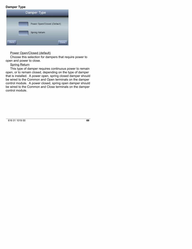
Power Open/Closed (default)Choose this selection for dampers that require power to
open and power to close.Spring ReturnThis type of damper requires continuous power to remain
open, or to remain closed, depending on the type of damperthat is installed. A power open, spring closed damper shouldbe wired to the Common and Open terminals on the dampercontrol module. A power closed, spring open damper shouldbe wired to the Common and Close terminals on the dampercontrol module.
70 616 01 1019 00
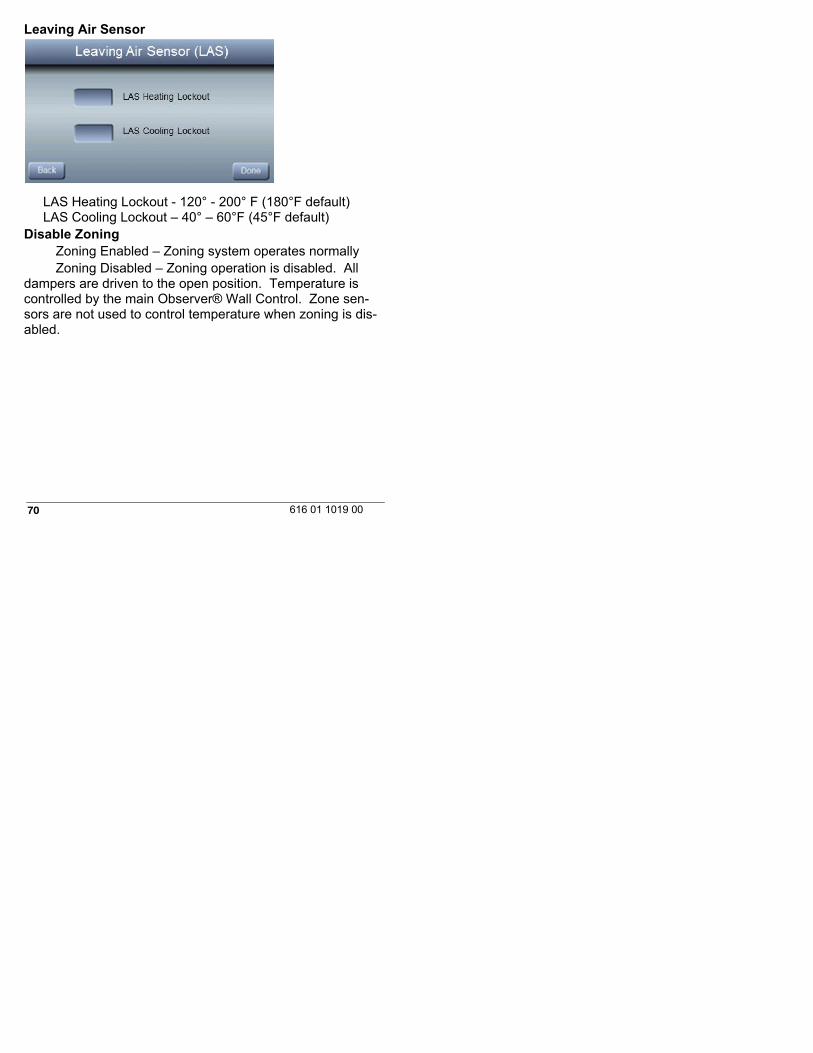
Leaving Air Sensor
LAS Heating Lockout - 120° - 200° F (180°F default)LAS Cooling Lockout – 40° – 60°F (45°F default)
Disable ZoningZoning Enabled – Zoning system operates normallyZoning Disabled – Zoning operation is disabled. All
dampers are driven to the open position. Temperature iscontrolled by the main Observer® Wall Control. Zone sen-sors are not used to control temperature when zoning is dis-abled.
71616 01 1019 00
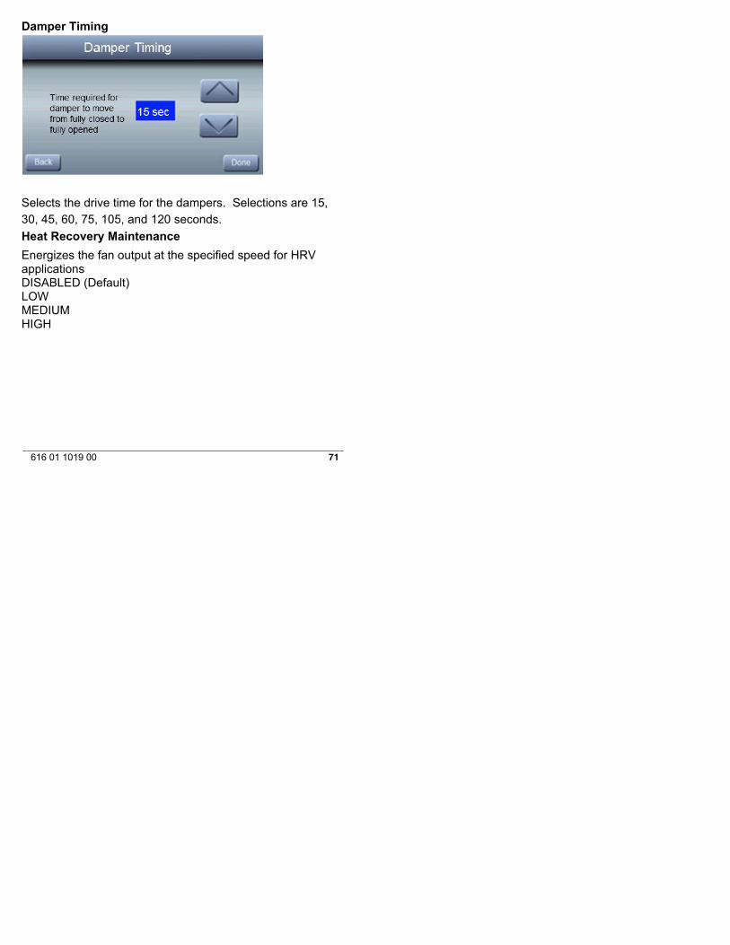
Damper Timing
Selects the drive time for the dampers. Selections are 15,30, 45, 60, 75, 105, and 120 seconds.
Heat Recovery Maintenance
Energizes the fan output at the specified speed for HRVapplicationsDISABLED (Default)LOWMEDIUMHIGH

72 616 01 1019 00
Daughter BoardWhen non-communicating equipment is used, the daughterboard may be needed. The daughter board provides outputsfor non-communicating indoor equipment and non-communi-cating outdoor equipment. The daughter board should beused in the following applications:
S Non-communicating indoor unit with non-communi-cating outdoor unit.
S Communicating furnace with any heat pump.S Communicating furnace with any two-stage A/C or
HP.S Communicating fan coil with any two-stage A/C or
HP.
73616 01 1019 00
Operational InformationAuto Mode
When Auto Mode is enabled (factory default) a change fromheat to cool (or vice versa) will not occur until the currentcycle is satisfied and an opposite mode demand has existedfor 30 minutes. If the set-point is changed, the 30 minutetimer is deleted.
Enable/Disable Auto Changeover mode (default = En-able).
Auto Changeover Time may be adjusted 5 to 120 minutes,(default = 30 minutes).Setpoint Deadband
The minimum difference enforced between heating and cool-ing desired temperatures. This can allow one setting to“push” the other to maintain this difference.
0 to 6ºF (0 to 3ºC), (default = 2ºF)Offsets
This option allows calibration (or deliberate mis-calibration)of the temperature and humidity sensors. These offsets areadded to the actual temperature/humidity values (default =0).
Temperature Offset: -5ºF to +5ºF (-3ºC to +3ºC)Outside Temp Offset: -5ºF to +5ºF (-3ºC to +3ºC)Humidity Offset: -10 to +10%
Cycles Per Hour
Maximum cycles per hour = 4 (default) or 6.

74 616 01 1019 00
Programming
ON (default) - allows program schedule to be set by user.OFF - system becomes non--programmable
Smart Recovery
This feature applies to programmable operation only. Thecontrol will start recovery 90 minutes prior to schedulechange in both heating and cooling mode. Refer to opera-tional information for more detail.
On or Off (default = On)
75616 01 1019 00
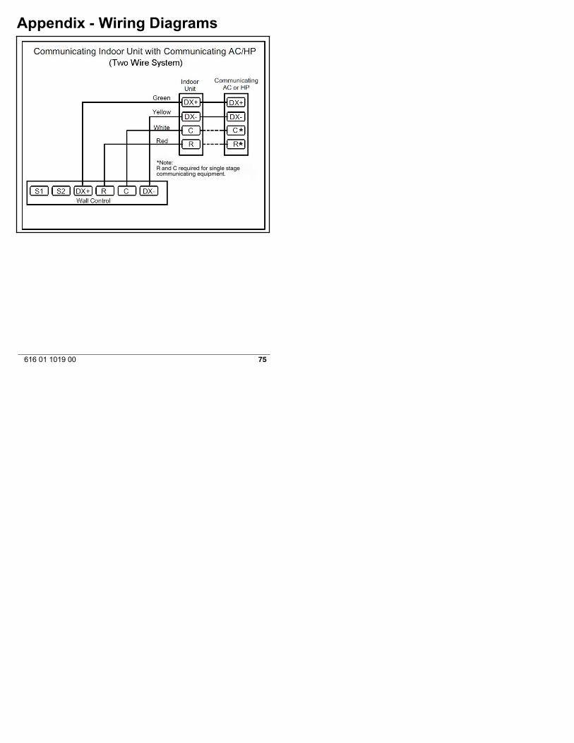
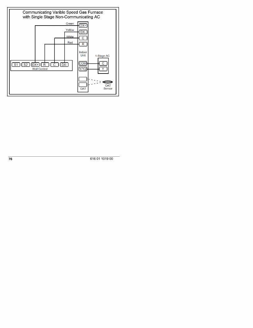
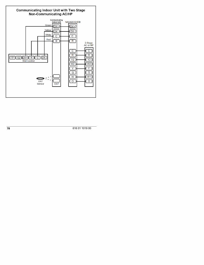
Appendix - Wiring Diagrams
*Note:R and C required for single stagecommunicating equipment.
76 616 01 1019 00

77616 01 1019 00
78 616 01 1019 00

79616 01 1019 00
Non-Communicating Indoor Unit withNon-Communicating Outdoor
NAXA00101DB
Green
Yellow
White
Red
OATSensor
Non-CommunicatingOutdoor
W2
Y2
C
Y
R
Y2
W2
C
R
WallControl
OAT
DX+
R
C
DX-
Y
G
W
O O
G
W1
C
Y/Y2
R
W2
G
W1
DX+
R
C
DX-
Non-CommunicatingIndoor
80 616 01 1019 00
All trademarks are the property of the respective owners.Wi-Fi® is a registered trademark of the Wi-Fi Alliance Corporation.
Copyright 2014 International Comfort ProductsLewisburg, TN 37091 USA