Embed Size (px)
Citation preview
Singapore Polytechnic
Singapore Maritime Academy
&Maritime Institute Of William Barentsz
Bachelor Degree in Maritime Operations (BMO)MA9022
Diesel Technology & EmissionsCOMMON RAIL FUEL SYSTEM AND EXHAUST VALVE
ACTUATION WITH ELECTRONIC INJECTION CONTROL
Pururav NagarajDate: 29 August 2006This assignment is done in the fulfillment of bachelor degree in maritime operations for diesel technology and emissions Unit 2: Marine Diesel-Technology Trends.
1
1. What has driven the innovation of this technology?
In the marine market, the Annex VI of MARPOL 73/78 and the Technical Code on the Control of Emissions of Nitrogen Oxides from Marine Diesel Engines came into force on 18th may 2005.
Both at international and regional levels, more stringent legislation stipulates and regulates levels of smoke, particulates, NOx, SOx and other pollutants generated from marine diesel engines.
New emission reduction technologies, offered as standard on new engines, can often be retrofitted on marine or power plant installations already in operation. These installations can then benefit from technical improvements not originally available when they first entered into service.
EPA legislation is example of how limits on particulate matter and NOx have changed over the years: from 1988 to 2010 requirements for emission reduction are rising more than 95%.
So in conclusion, the need for a clean environment and reducing health hazards to human beings forced the MARPOL and the marine industry to innovate new technologies for reducing harmful emissions from marine diesel engines.
2
1.1. Briefly describe how this technology works.
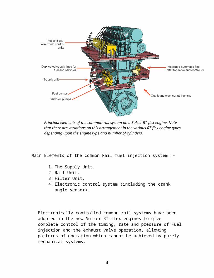
Principal elements of the common-rail system on a Sulzer RT-flex engine. Note that there are variations on this arrangement in the various RT-flex engine types depending upon the engine type and number of cylinders.
Main Elements of the Common Rail fuel injection system: -
1. The Supply Unit.2. Rail Unit.3. Filter Unit.4. Electronic control system (including the crank angle sensor).
Electronically-controlled common-rail systems have been adopted in the new Sulzer RT-flex engines to give complete control of the timing, rate and pressure of Fuel injection and the exhaust valve operation, allowing patterns of operation which cannot be achieved by purely mechanical systems.
3
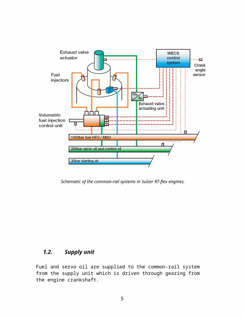
Schematic of the common-rail systems in Sulzer RT-flex engines.
1.2. Supply unit
Fuel and servo oil are supplied to the common-rail system from the supply unit which is driven through gearing from the engine crankshaft.
4
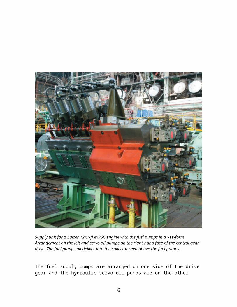
Supply unit for a Sulzer 12RT-fl ex96C engine with the fuel pumps in a Vee-formArrangement on the left and servo oil pumps on the right-hand face of the central gear drive. The fuel pumps all deliver into the collector seen above the fuel pumps.
The fuel supply pumps are arranged on one side of the drive gear and the hydraulic servo-oil pumps are on the other side. This pump arrangement allows a very short, compact supply unit with reasonable service access. The numbers, size and arrangement of Pumps are adapted to the engine type and the number of engine cylinders.
The fuel supply pumps are driven through a camshaft with three-lobe cams. This camshaft cannot be compared with the traditional engine camshaft. It is very short and of much smaller diameter, and is quite differently loaded.
5
The fuel delivery volume and rail pressure are regulated according to engine requirements through suction control with helix-controlled filling volume regulation of the fuel supply pumps. Suction control was selected for its low power consumption as no excess fuel is pressurized.
The fuel pumps deliver the pressurized fuel to an adjacent collector from which two independent, double walled delivery pipes lead upwards to the fuel rail. Each delivery pipe is dimensioned for full fuel flow. The collector is equipped with a safety relief valve set to 1250 bar.
The supply unit supplies both servo oil and control oil to the rail unit.
Servo oil - Servo oil is used for exhaust valve actuation and control. It is supplied by a number of swashplate-type axial piston hydraulic pumps mounted on the supply unit. The oil used in both the servo and control oil systems is standard engine system lubricating oil, and is simply taken from the delivery to the engine lubrication system.
Control oil - The control oil serves as the working medium for all rail valves of the injection control units (ICU). The working pressure of the control oil is maintained constant to ensure precise timing in the ICU. It is also used to prime the servo oil rail at standstill thereby enabling a rapid starting of the engine.
1.3. Rail Unit
The rail unit contains the rail pipes and associated equipment for the fuel, servo oil and control oil systems. The starting air system is not included in the rail unit.
The hydraulic pipes for the exhaust valve drives arch up from the exhaust valve actuators on the servo oil rail, and the sets of triple high-pressure fuel injection pipes rise up from the injection control units on the fuel rail.
The volume of the common-rail system and the supply rate from the fuel supply pumps are such that the rail pressure is very stable with negligible pressure drop after each injection.
6
A D B C
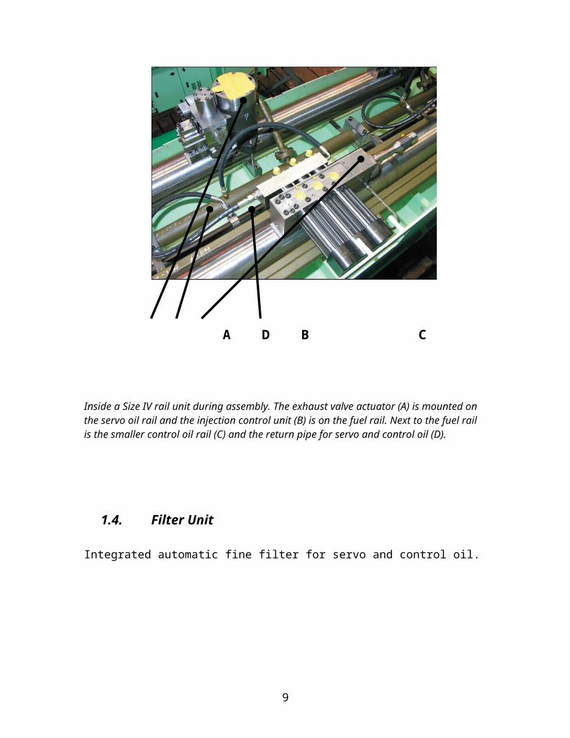
Inside a Size IV rail unit during assembly. The exhaust valve actuator (A) is mounted on the servo oil rail and the injection control unit (B) is on the fuel rail. Next to the fuel rail is the smaller control oil rail (C) and the return pipe for servo and control oil (D).
1.4. Filter Unit
Integrated automatic fine filter for servo and control oil.
7
1.5. Electronic Control System
All functions in the Sulzer RT-flex system are controlled and monitored through the Wärtsilä Engine Control System (WECS). This is a modular electronic system with separate microprocessor control units for each cylinder, and overall control and supervision by duplicated microprocessor control units. The latter provide the usual interface for the electronic governor and the shipboard remote control and alarm systems.
An essential input signal for WECS is the engine crank angle. This is measured very accurately by two sensors driven from a stub shaft on the free end of the crankshaft. The sensors are able to give the absolute crank angle position immediately that electrical power is applied. With RT-flex engines, the remote control sends engine manoeuvring commands to the WECS. The remote control processes speed signals from the engine order telegraph according to a defined engine load program and fuelling limitations, and generates a fuel reference signal for the WECS.
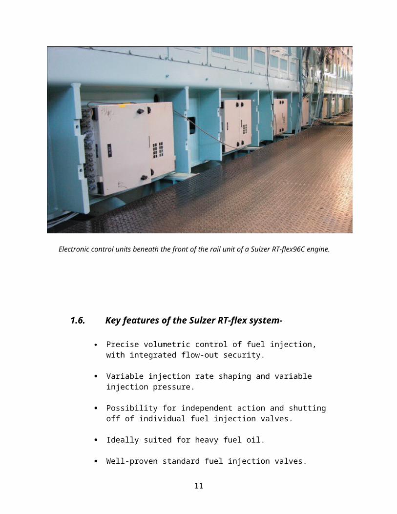
Electronic control units beneath the front of the rail unit of a Sulzer RT-flex96C engine.
8
1.6. Key features of the Sulzer RT-flex system-
Precise volumetric control of fuel injection, with integrated flow-out security.
Variable injection rate shaping and variable injection pressure.
Possibility for independent action and shutting off of individual fuel injection valves.
Ideally suited for heavy fuel oil.
Well-proven standard fuel injection valves.
Proven, high-efficiency common-rail pumps.
Lower levels of vibration and internal forces and moments.
Steady operation at very low running speeds with precise speed regulation.
Smokeless operation at all speeds.
9
2. How does this technology apply to control emission?
The superior combustion performance with the common-rail system is achieved by maintaining the fuel injection pressure at the optimum level right across the engine speed range. In addition, selective shut-off of single injectors and an optimised exhaust valve timing help to keep smoke emissions below the visible limit at very low speeds.
The precision and flexibility in engine setting given by the RT-flex system facilitates compliance with the NOX regulation of Annex VI of the MARPOL 73/78 convention, usually referred to IMO NOX regulation.
The flexibility of the RT-flex engines will also allow a lowering of NOX emissions if the corresponding increase in BSFC is acceptable. With common-rail injection, a wide variety of injection patterns can be generated. The injected quantity of fuel can be divided, for pre-injection, triple injection, etc. The Sulzer RT-flex engine, with its individual fuel valve control, also has the unique ability to vary individually the injection timing and sequence between the three fuel injectors in each cylinder and thus to generate a tailor-made heat release.
In engine tests, this degree of flexibility has proved useful to reach NOX emissions of 20 per cent below the IMO NOX limit with a moderate BSFC increase of 2.3 per cent.
10
3. What are the precautions involved in running this kind of technology?
Reliability and safety has the utmost priority in the common rail RT-flex system.
The duplicated high-pressure delivery pipes have stop cocks at both ends to isolate any failed pipe. Each single pipe is adequate for the full delivery. All high pressure pipes are double-walled for safety.
Every injection nozzle is independently monitored and controlled by the WECS. In case of difficulties, such as a broken high pressure line or a malfunctioning injector, the affected injection valve can be cut out individually without losing the entire cylinder.
If the stroke measuring sensor fails, the WECS system switches the ICU to a pure time control and triggers the signal based on the timing of the neighbouring cylinders.
11
References:-
Wartsila 2006 Technical papers - The Sulzer RT-Flex common rail system described [Online] Available from: www.wartsila.com/.../ship_power/media_publications/technical_papers/sulzer /rtflex_description_20040816.pdf [Accessed on 18 august 2006].
Wartsila Services- Environmental Solutions [Online]Available from:http://www.wartsila.com/en,service,0,solution,12029574846768,4009646227060296,,2900.htm
[Accessed on 18 august 2006]
12