Embed Size (px)
Citation preview

Common and Normal Mode Currents in PMSM PWM Drives
Radu Marţiş, Radu Siecoban, Claudia Marţiş, Loránd Szabó Technical University of Cluj-Napoca, Dept. of Electrical Machines and Drives
Cluj-Napoca, Romania [email protected]
Abstract—The paper approaches the high-frequency equivalent circuit of permanent magnet synchronous machines (PMSM) with different pole number, and its response to PWM-based supplying current. The model is implemented in MATLAB-Simulink, and the phase currents, as well as the common and normal mode currents are analyzed.
Keywords—permanent magnet synchronous machine, high-frequency equivalent circuit, parasitic capacitance, common mode current, normal mode current
I. INTRODUCTION PMSM is the most suitable electrical machine for small
electrical actuated automotive applications, due to their high power density and high efficiency. In order to reduce torque ripple and improve the dynamic performances of the PMSM drives different control strategies are implemented [1]. An important consequence of using different control strategies, are harmonics within the voltage, which in turn are responsible for high frequency currents that can appear in the machine. The high frequency current harmonics can excite the parasitic capacitances inside the electrical motor and generate capacitive and conductive disturbances within the system. Disturbing current components can thus flow in both common-mode and normal mode paths [2]. Several research works have been performed to model and evaluate the high-frequency behavior of PMSM drives, most of them focused on high-frequency model development and analysis, equivalent high-frequency circuit parameters estimation and/or computation [2]. However no research efforts have been oriented to deal with the influence of PMSM topology on its high-frequency response.
The paper proposes an analysis of the common and normal mode currents for PMSMs with different number of slots/number of poles combination, using a Space Vector Modulation (SVM) based control strategy. Section II presents the high-frequency equivalent circuit of the machine [4], and its parameters computation. The model is then implemented and analyzed in Section III, for speed-controlled PMSM. The performed simulations and the obtained results are presented in Section IV.
II. PMSM HIGH-FREQUENCY EQUIVALENT CIRCUIT PARAMETERS
As mentioned previously, in order to evaluate the parasitic currents that can appear in the system, a high-frequency equivalent circuit for each phase of the motor was used (Fig. 1) [4].
Fig. 1. Equivalent circuit for one phase [7]
The circuit parameters are as following:
- Rs - the phase resistance; - Rp - the resistance modeling the eddy current losses
given by:
(1)
where peddy represents the specific eddy loss of the stator core, ms the mass of the stator, and IphN the rated phase current [2],
- Ls is the phase inductance computed as:
(2)
with Φph is the phase linkage magnetic flux.
When addressing capacitive disturbances to the system, three types of parasitic capacitances have to be taken into account:
- turn to turn capacitance; - capacitance between two separate coils; - stator to ground capacitance.
A. Turn to turn capacitance This type of capacitance can appear between every two
turns within a coil [8]. Considering that the distance between two adjacent turns is very small, it can be presumed that the electric field lines close only through an adjacent turn. Also, due to the symmetry of the coil, it can be supposed that the equivalent capacitance between two turns will be the same for every group of two turns within the same coil [5].
978-1-5090-2067-6/16/$31.00 ©2016 IEEE
2016International Symposium on Power Electronics,Electrical Drives, Automation and Motion
500

Fig. 2. Parasitic capacitances between turns
Fig. 2 [3] shows the capacitance matrix between 4 wires
(having circular and rectangular cross-sections). This can be extrapolated to create a coil with any number of turns.
The turn to turn capacitance can be calculated by using:
(3)
where e0 is the vacuum permittivity, er the material (copper) permittivity, sis the width of the insulation used on the copper wires and Da the diameter of the wire. Θ is the angle at which the electric flux closes between two adjacent turns and can be computed as follows:
(4)
The coil stray capacitance can be calculated using the turn to turn capacitance:
(5) where Nt is the number of turns in one coil [6].
B. Capacitance between two separate coils In machines that have double layered windings (two coils
in the same slot) another type of parasitic capacitance occurs. This can be estimated as 20% of the phase stray capacitance, given the fact that only part of the turns from each coil is in close proximity with the turns of another phase.
Of course this is specific to each motor, and its value can vary, depending on the number of turns from each coil.
C. Stator to ground capacitance The stator to ground capacitance that can induce parasitic
common-mode currents in the system can be computed as:
(6)
III. IMPLEMENTATION OF THE PMSM HIGH-FREQUENCY MODEL
Three topologies of surface mounted PMSMs are used in order to validate the proposed study. All of them use an identical stator stack with 36 slots. The stator windings and the rotors are different, having 4, 6 and 8 poles respectively. The cross-sections of the three PMSMs under study are shown in Fig. 3.
Fig. 3. PMSM topologies with different rotor pole numbers
a) 4 poles b) 6 poles c) 8 poles
The high-frequency equivalent circuit parameters for each topology are given in Table I.
TABLE I. PMSM PARAMETERS 4 poles 6 poles 8 poles
IphN 1.77 A 1.77 A 1.77 A
Ls 41.7248 mH 24.50 mH 16.4274 mH Cp 7.147 pF 3.409 pF 1.903 pF Cg 4.727 pF 2.26 pF 1.259 pF
Rp 1.351 kΩ 3 kΩ 5.403 kΩ Rph 20.58 Ω 9.732 Ω 5.48 Ω
The parameters were obtained analytically using Mathcad. For the validation of the results, the parasitic capacitance between two phases was calculated also by using a numerical approach. JMAG Designer was applied for this. The 3D models of the PMSMs taken into study were built up. The stator model of the 4 poles PMSM is given in Fig. 4.
Fig. 4. 3D model of the 4 poles PMSM variant's stator
It is known that a capacitance appears between two surfaces which are charged with different voltages, and so, one coil will have a 1 V supply, whilst the other will have
501

0 V. This method provides the phase to phase capacitance which is needed in order to validate the obtained analytical data. The results obtained via the two methods are given in Table II.
TABLE II. ANALYTICAL VS. NUMERICAL COMPUTATION OF PARASITIC CAPACITANCE BETWEEN TWO PHASES
Analytical computation
Numerical computation
Relative error
4 poles 1.4294 pF 1.52 pF 5.1%
6 poles 0.6818 pF 0.67 pF 4.1%
8 poles 0.3806 pF 0.39 pF 3.5%
As it can be seen from the results given in Table II, the initial estimation that the parasitic capacitance between two phases is 20% of the phase own parasitic capacitance was proved also by means of numerical computations.
Based on the parameters of the three-phase PMSM, the high-frequency equivalent circuit was implemented in MATLAB-Simulink (see Fig. 5).
Fig. 5. PMSM high-frequency model
The main blocks of the MATLAB-Simulink PMSM high frequency model, as well as the voltage supply are given in Fig. 5. The phase high-frequency equivalent circuit is presented in Fig. 6, with the parameters defined in Section II.
Fig. 6. Phase high-frequency equivalent circuit
In order to analyze the influence of the number of stator slots/number of rotor poles combination on the common and normal mode currents, the machine is fed via a power converter (with the topology given in Fig. 7) and controlled using a Space Vector Modulation control strategy.
Fig. 7. Power inverter
IV. SIMULATION RESULTS The phase currents are given in Fig. 8. The frequency of
the fundamental is 50 Hz, 75 Hz and 100 Hz respectively, according to the number of poles.
a) 4 poles
b) 6 poles,
c) 8 poles
Fig 8. Phase currents for the studied topologies
502
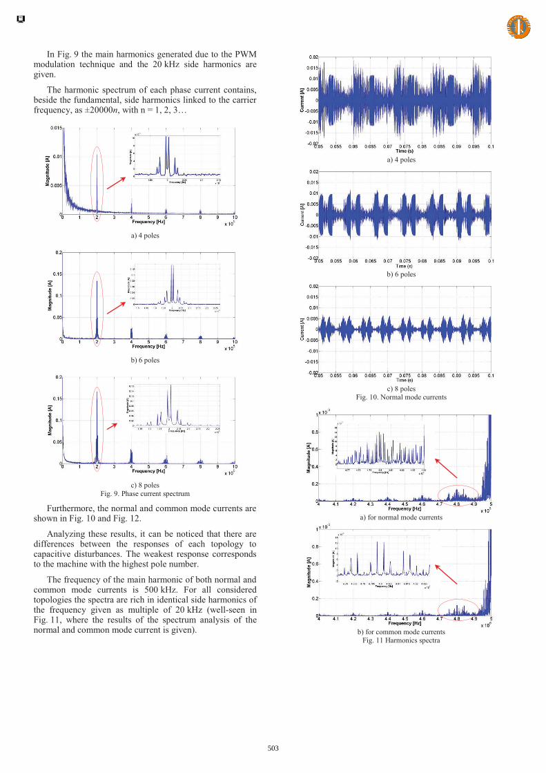
In Fig. 9 the main harmonics generated due to the PWM modulation technique and the 20 kHz side harmonics are given.
The harmonic spectrum of each phase current contains, beside the fundamental, side harmonics linked to the carrier frequency, as ±20000n, with n = 1, 2, 3…
a) 4 poles
b) 6 poles
c) 8 poles
Fig. 9. Phase current spectrum
Furthermore, the normal and common mode currents are shown in Fig. 10 and Fig. 12.
Analyzing these results, it can be noticed that there are differences between the responses of each topology to capacitive disturbances. The weakest response corresponds to the machine with the highest pole number.
The frequency of the main harmonic of both normal and common mode currents is 500 kHz. For all considered topologies the spectra are rich in identical side harmonics of the frequency given as multiple of 20 kHz (well-seen in Fig. 11, where the results of the spectrum analysis of the normal and common mode current is given).
a) 4 poles
b) 6 poles
c) 8 poles
Fig. 10. Normal mode currents
a) for normal mode currents
b) for common mode currents
Fig. 11 Harmonics spectra
503

a) 4 poles
b) 6 poles
c) 8 poles
Fig. 12. Common mode currents
CONCLUSIONS AND FUTURE WORK
The paper aims the analysis of PMSM topology influence on the common and normal mode disturbances in PMSM Space vector Modulation based controlled drives. A high-frequency equivalent circuit is proposed and implemented in MATLAB-Simulink. Phase currents and common and normal mode currents are depicted. At first sight, the magnitude of the normal and common mode currents harmonics are lower for machines with a higher number of poles. Furthermore, Table III shows the normal and common mode currents as rms value and percentage compare to the phase current rms.
TABLE III. NORMAL AND COMMON MODE CURRENT MAXIMAL AND PERCENTAGE BASED VALUES FROM TOTAL PHASE CURRENT
4 poles 6 poles 8 poles Normal mode current [A] 0.02 0.01 0.007
Normal mode current [%] 1 0.5 0.35
Common mode current [A] 0.05 0.02 0.01
Common mode current [%] 2.5 1 0.5
Further investigations are needed in order to develop an analytical procedure for harmonic order identification and description, as a function of machine topology, operating speed and control strategy.
V. ACKNOWLEDGEMENT This work was supported by Joint Applied Research
Projects “CEMIVA-Coupled Electromagnetic Interferences and Vibration Analysis for Safe Automotive ELECTRICAL Actuators” funded by Romanian UEFISCDI under PCCA 252/2014 research grant.
REFERENCES [1] G. Jayabaskaran, B. Adhavan, and V. Jagannathan. "Torque ripple
reduction in Permanent Magnet Synchronous Motor driven by field oriented control using Iterative Learning Control with space vector pulse width modulation," in Proceedings of the 2013 International Conference on Computer Communication and Informatics (ICCCI '13), Coimbatore (India), 2013.
[2] O.A. Mohammed, et al., "High Frequency Modeling of Permanent Magnet Synchronous Motor Drive," in Proceedings of the IEEE International Electric Machines & Drives Conference (IEMDC '07), Antalya (Turkey), pp. 318-321, 2007.
[3] K. Gulez, et al. "High-frequency common-mode modeling of permanent magnet synchronous motors," IEEE Transactions on Electromagnetic Compatibility, vol. 50, no. 2, pp. 423-426, 2008.
[4] X. Pan, R. Ehrhard, R. Vick, "An extended high frequency model of permanent magnet synchronous motors in hybrid vehicles," in Proceedings of the 10th International Symposium on Electromagnetic Compatibility (EMC '2011), York (U.K.), pp. 690-694, 2011.
[5] L. Ran, et al. "Conducted electromagnetic emissions in induction motor drive systems. II. Frequency domain models," IEEE Transactions on Power Electronics, vol. 13, no. 4, pp. 768-776, 1998.
[6] A. Boglietti, A. Cavagnino and M. Lazzari, "Experimental high-frequency parameter identification of AC electrical motors," IEEE Transactions on Industry Applications, vol. 43, no. 1, pp. 23-29, 2007.
[7] G. Grandi, D. Casadei and U. Reggiani, "Equivalent circuit of mush wound AC windings for high frequency analysis," in Proceedings of the IEEE International Symposium on Industrial Electronics (ISIE '97), Guimaraes (Portugal), vol. 1, pp. SS201-SS206, 1997.
[8] A. Boglietti and E. Carpaneto, "Induction motor high frequency model," in Conference Record of the 1999 IEEE Industry Applications Conference (IAS '99), Phoenix (U.S.A.), vol. 3, pp. 1551-1558, 1999.
504