Embed Size (px)
Citation preview
CommercialPackage UnitsRRCF- Cooling OnlyRREF- Electric HeatRRGF- Gas Heat
FORM NO. R11-814 REV. 11Supersedes Form No. R11-814 Rev. 10
6.5 & 7.5 NOMINAL TON UNITS[22.9 & 26.4 kW]
“CERTIFIED UNDER THEA.R.I. CERTIFICATION
PROGRAM—A.R.I.STANDARD 210”

2
TABLE OF CONTENTSModel Number Designation . . . . . . . . . . . . . . . . . . . . . . . . . . . . 2Unit Features . . . . . . . . . . . . . . . . . . . . . . . . . . . . . . . . . . . . . . . . 3Accessories . . . . . . . . . . . . . . . . . . . . . . . . . . . . . . . . . . . . . . . . . . 3Physical Data . . . . . . . . . . . . . . . . . . . . . . . . . . . . . . . . . . . . . . . . 4Performance Data . . . . . . . . . . . . . . . . . . . . . . . . . . . . . . . . . . . . 5Selection Procedure . . . . . . . . . . . . . . . . . . . . . . . . . . . . . . . . . . 6Cooling Performance Data. . . . . . . . . . . . . . . . . . . . . . . . . . . . . . 7Indoor Blower Performance . . . . . . . . . . . . . . . . . . . . . . . . . . . . 8General Information . . . . . . . . . . . . . . . . . . . . . . . . . . . . . . . . . . 9Unit Dimensions . . . . . . . . . . . . . . . . . . . . . . . . . . . . . . . . . . . . 10Accessory Information . . . . . . . . . . . . . . . . . . . . . . . . . . . . . . 11-14Electrical Data . . . . . . . . . . . . . . . . . . . . . . . . . . . . . . . . . . . . 15-17Typical Wiring Schematics . . . . . . . . . . . . . . . . . . . . . . . . . . 18-22Sequence of Operation . . . . . . . . . . . . . . . . . . . . . . . . . . . . . . 23Limited Warranty . . . . . . . . . . . . . . . . . . . . . . . . . . . . . . . . . . . . 23Sample Specifications . . . . . . . . . . . . . . . . . . . . . . . . . . . . . . . . 24
A NEW BREED OF ROOFTOPSDESIGNED FOR THE 90’S.Rheem® combined years of proven product reliability and hightech engineering to develop this line of versatile rooftops. Thisresulted in a flexible design with the features of earlier models ina fully accessible, totally new compact cabinet.
MODEL NUMBER DESIGNATIONR RG F— 201 076 C K R
Type of GasR-NaturalA-Natural (Canadian Models)Drive PackageK-Standard L-OptionalElectrical CharacteristicsC-3/60/208/230D-3/60/460 Y-3/60/575Nominal Tons Cooling Capacity076-7.5 Tons [26.4 kW]065-6.5 Tons [22.9 kW]Electric Heat-Total KW015/020/030/040 KWSee Electrical Data Table foractual KW value.Heating Input201 = 200,000 BTUH [58.6 kW]131 = 135,000 BTUH [39.6 kW]Design SeriesRooftop—Type HeatingRG-Gas RC-Cool OnlyRE-Electric Resistance HeatRheem
[ ] Designates Metric Conversions
3[ ] Designates Metric Conversions
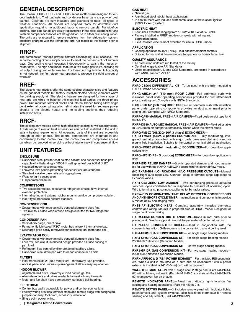
GENERAL DESCRIPTIONThe Rheem RRCF-, RREF- and RRGF- series rooftops are designed for out-door installation. Their cabinets and condenser base pans are powder coatpainted. Cabinets are fully insulated and gasketed to resist all types ofweather conditions. All models are shipped ready for downflow ductapplication requiring no additional labor to remove panels. For sideflowducting, duct cap panels are easily repositioned in the field. Economizer andfresh air damper accessories are designed for use in either duct configuration.The units are evacuated to remove moisture from the refrigeration system,precisely charged with the refrigerant and run tested at the factory prior toshipment.
RRGF-The combination rooftops provide comfort conditioning in all seasons. Twoseparate cooling circuits supply cool air to meet the demands of hot summerdays. One cooling circuit operates independently to satisfy the needs onmilder days. The high heat model features a two-stage gas valve, allowing forfull output during cold winter weather. For those cool nights when full capacityis not needed, the first stage heat operates to produce the right amount ofwarm air.
RREF-The electric heat models offer the same cooling characteristics and featuresas the gas heat models but factory installed electric heating elements warmthe building supply air. The electric heaters are designed for two stages ofheat and are wired to balance the electrical load across the three phasepower. Unit mounted terminal blocks and internal branch fusing allow singlepoint external power wiring which eliminates the need for separate powercircuits to the electric heater and the cooling sections, thus reducinginstallation costs.
RRCF-The cooling only models deliver high efficiency cooling in two capacity steps.A wide range of electric heat accessories can be field installed in the unit tosatisfy heating requirements. All operating parts of the unit are accessiblethrough exterior panels. The control components are mounted in oneconveniently located control box. The control box and compressor accesspanel can be removed for servicing without interfering with condenser air flow.
UNIT FEATURESENCLOSURE• Galvanized steel powder coat painted cabinet and condenser base pan
capable of withstanding a 1000-HR salt spray test per ASTM B 117.• Insulated indoor section panels.• Louvered inlet panels protecting condenser coil are standard.• Standard forkable base rails with rigging holes.• Weather tight construction.• Full perimeter base rail.
COMPRESSORS• Two sealed hermetics, in separate refrigerant circuits, have internal
overload protection.• Internal spring and external rubber mounts provide compressor isolation.• Insert type crankcase heaters standard.
CONDENSER COIL• Copper tubes with mechanically bonded aluminum plate fins.• Two-row, four-sided wrap-around design circuited for two refrigerant
systems.
CONDENSER FAN• Vertical discharge, direct drive.• Permanently lubricated “PSC” motor has inherent thermal overload.• Discharge grille easily removable for access to fan, motor and coil.
EVAPORATOR COIL• Copper tubes with mechanically bonded aluminum plate fins.• Four row, two circuit, interlaced design provides full-face cooling at
part load.• Refrigerant flow control by filter-protected capillary tubes.• Galvanized steel drain pan with threaded connector on side.
FILTERS• Filter frame holds 2" [50.8 mm] filters—throwaway type provided.• Access panel and unique clip arrangement allows easy replacement.
INDOOR BLOWER• Adjustable belt drive, forwardly curved centrifugal fan.• Alternate motors and drives available to meet job requirements.• Motor and fan shaft have permanently lubricated ball bearings.
ELECTRICAL• Control box easily accessible for power and control connections.• Factory wiring provides terminal strips and remote plugs with designated
jumpers for easy, fool-proof, accessory installation.• Single point power wiring.
GAS HEAT• Natural gas.• Aluminized steel tubular heat exchangers.• In shot burners with induced draft combustion air have spark ignition
(100% lockout) system.
ELECTRIC HEAT• Four sizes available ranging from 15 KW to 40 KW at 240 volts.• Factory installed in RREF- models complete with wiring and
appropriate fuses.• Field installed electric heat available for use in RRCF- model.
APPLICATION• Cooling operation to 45°F [7.2C]. Field add low ambient controls.• Shipped for vertical airflow—relocate two panels for horizontal airflow.
QUALITY ASSURANCE• All production units are run tested at the factory.• Certified to applicable ARI Standards.• Listed to applicable U.L. and CSA Standards, and tested in accordance
with ANSI Standard Z21.47.
ACCESSORIESRXRD-CBD10 DIFFERENTIAL KIT—To be used with the fully modulatingRXRQ-HM51Z economizer.
RXKG-ABD24 24" [610 mm] ROOF CURB—Full perimeter curb withinsulation panel under operating components provides for duct attachmentprior to setting unit. Complies with NRCA Standards.
RXKG-E50 14" [356 mm] ROOF CURB—Full perimeter curb with insulationpanel under operating components provides for duct attachment prior tosetting unit. Complies with NRCA Standards.
RXRF-CA50 MANUAL FRESH AIR DAMPER—Fixed position slot type for 0to 25% FA.
RXRF-DB50 AUTO MECHANICAL FRESH AIR DAMPER—Field adjustable(0-25%) fresh air damper automatically closes when the blower stops.
RXRQ-FM50Z (208/230/460V, 3 phase) ECONOMIZER—RXRQ-FM50Y (575V, 3 phase) ECONOMIZER—Fully modulating, inte-grated, enthalpy controlled, with major parts pre-assembled and wired forplug-in field installation. Suitable for horizontal or vertical airflow application.
RXRQ-HM51Z (RSI-full modulating) ECONOMIZER—For downflow appli-cations only.
RXRQ-HP51Z (RSI- 3 position) ECONOMIZER—For downflow applicationsonly.
RXRP-E50 RELIEF DAMPER—Gravity operated damper and hood assem-bly for use with the RXRQ-FM50Z(Y) economizer in either airflow mode.
(HI) RXAB-B01 (LO) RXAC-B01 HI/LO PRESSURE CUTOUTS—Manualreset High; auto reset Low. Connect leads to terminal strip; capillaries toSchrader valves.
RXRT-C53 ZERO LOW AMBIENT—Two condensing pressure actuatedswitches, cycle condenser fan in response to pressure of operating cycle.Wire to terminal strip; connect capillaries to Schrader valves.
RXRW-C55 COMBINATION TIME DELAY BETWEEN COMPRESSORSAND ANTI-SHORT CYCLE TIMER—Instructions and components to provide5 minute delay and staging relay.
RXSE-AF ELECTRIC HEAT—Complete assembly includes elements,controls and wiring. Mounts in prepared area of RRCF- model. Designed forsingle point power wiring.
RXRM-EB50 CONCENTRIC TRANSITION—Drops in roof curb prior toplacing unit. Directs supply air around the perimeter of center return duct.
RXRN-EE50 CONCENTRIC GRILLE—Used in conjunction with theconcentric transition. Grille mounts to the concentric ducts at ceiling level.
RXRJ-GP01R GAS CONVERSION KIT—For single stage heating models.
RXRJ-GP03R GAS CONVERSION KIT—For single stage heating models—2000-4500' elevation (Canadian Models).
RXRJ-GP09R GAS CONVERSION KIT—For two stage heating models.
RXRJ-GP10R GAS CONVERSION KIT—For two stage heating models—2000-4500' elevation (Canadian Models).
RXRX-AFF01C & D (RSI) POWER EXHAUST—For the listed RSI economiz-ers. When a unit is mounted on a curb and an economizer with a powerexhaust is installed, a 24” [610mm] curb will be required.
WALL THERMOSTAT—24 volt, 2 stage cool, 2 stage heat (Part #41-21444-01) with subbase, automatic (Part #41-21445-01) or manual (Part #41-21443-02) changeover; fan on or auto.
REMOTE INDICATOR PANEL—Panel has indicator lights to show fancooling and heating operations, (Part #41-41946-01).
REMOTE STATUS PANEL—Kit includes remote panel with indicator lights,potentiometer and system switches, also has room thermostat for remotesensing and adjustment, (Part #41-21946-12).
4
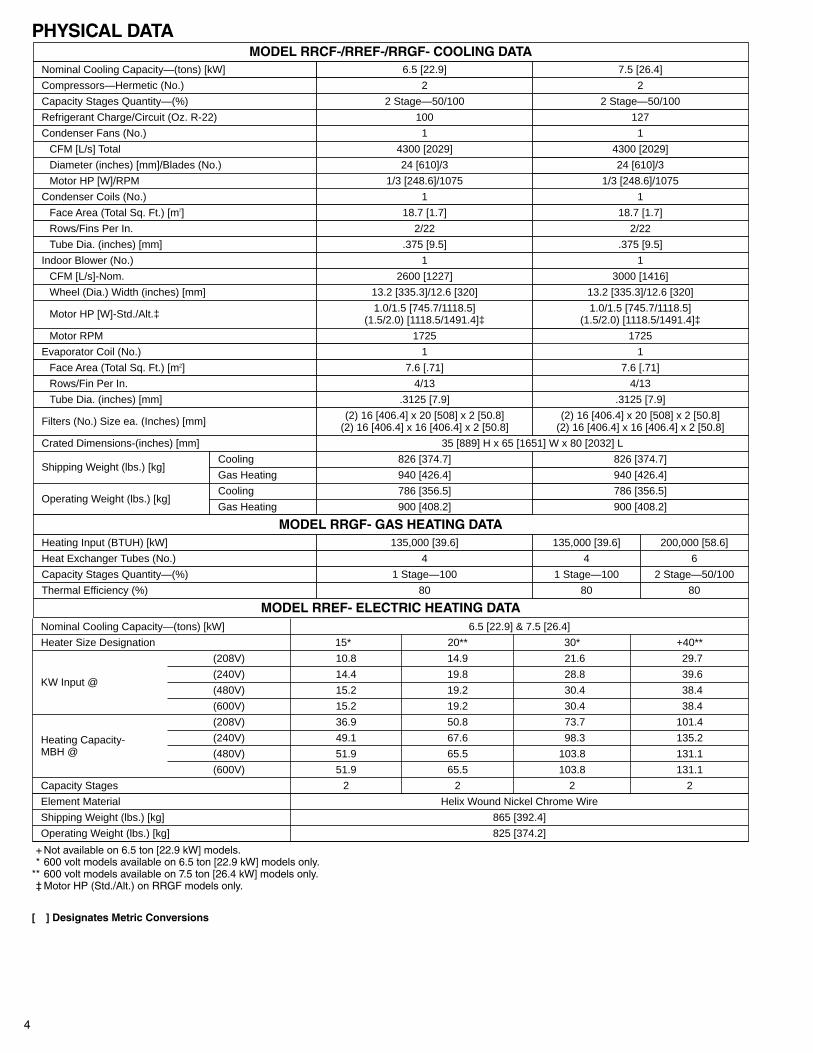
Compressors—Hermetic (No.)
Condenser Coils (No.)
2
Capacity Stages Quantity—(%)
1
2 Stage—50/100
Refrigerant Charge/Circuit (Oz. R-22)
1
100
Condenser Fans (No.)
80
1
CFM [L/s] Total
2 Stage—50/100
4300 [2029]
MODEL RRCF-/RREF-/RRGF- COOLING DATA
6
200,000 [58.6]
Diameter (inches) [mm]/Blades (No.)
Nominal Cooling Capacity—(tons) [kW] 6.5 [22.9]
24 [610]/3
Motor HP [W]/RPM 1/3 [248.6]/1075
Face Area (Total Sq. Ft.) [m2] 18.7 [1.7]
Rows/Fins Per In. 2/22
Tube Dia. (inches) [mm] .375 [9.5]
Indoor Blower (No.) 1
CFM [L/s]-Nom. 2600 [1227]
Wheel (Dia.) Width (inches) [mm] 13.2 [335.3]/12.6 [320]
Motor HP [W]-Std./Alt.‡ 1.0/1.5 [745.7/1118.5](1.5/2.0) [1118.5/1491.4]‡
Motor RPM 1725
Evaporator Coil (No.) 1
Face Area (Total Sq. Ft.) [m2] 7.6 [.71]
Rows/Fin Per In. 4/13
Tube Dia. (inches) [mm] .3125 [7.9]
Filters (No.) Size ea. (Inches) [mm] (2) 16 [406.4] x 20 [508] x 2 [50.8](2) 16 [406.4] x 16 [406.4] x 2 [50.8]
Crated Dimensions-(inches) [mm] 35 [889] H x 65 [1651] W x 80 [2032] L
Shipping Weight (lbs.) [kg]Cooling 826 [374.7]
Gas Heating 940 [426.4]
Operating Weight (lbs.) [kg]Cooling 786 [356.5]
Gas Heating 900 [408.2]
MODEL RRGF- GAS HEATING DATAHeating Input (BTUH) [kW] 135,000 [39.6]
Heat Exchanger Tubes (No.) 4
Capacity Stages Quantity—(%) 1 Stage—100
Thermal Efficiency (%) 80
MODEL RREF- ELECTRIC HEATING DATA80
1 Stage—100
4
135,000 [39.6]
900 [408.2]
786 [356.5]
940 [426.4]
826 [374.7]
(2) 16 [406.4] x 20 [508] x 2 [50.8](2) 16 [406.4] x 16 [406.4] x 2 [50.8]
.3125 [7.9]
4/13
7.6 [.71]
1
1725
1.0/1.5 [745.7/1118.5](1.5/2.0) [1118.5/1491.4]‡
13.2 [335.3]/12.6 [320]
3000 [1416]
1
.375 [9.5]
2/22
18.7 [1.7]
1/3 [248.6]/1075
24 [610]/3
4300 [2029]
1
127
2 Stage—50/100
2
7.5 [26.4]
Nominal Cooling Capacity—(tons) [kW] 6.5 [22.9] & 7.5 [26.4]
Heater Size Designation 15*0 20** 30* +40**
KW Input @
(208V) 10.8 14.9 21.6 29.7
(240V) 14.4 19.8 28.8 39.6
(480V) 15.2 19.2 30.4 38.4
(600V) 15.2 19.2 30.4 38.4
Heating Capacity-MBH @
(208V) 36.9 50.8 73.7 101.4
(240V) 49.1 67.6 98.3 135.2
(480V) 51.9 65.5 103.8 131.1
(600V) 51.9 65.5 103.8 131.1
Capacity Stages 2 2 2 2
Element Material Helix Wound Nickel Chrome Wire
Shipping Weight (lbs.) [kg] 865 [392.4]
Operating Weight (lbs.) [kg] 825 [374.2]
PHYSICAL DATA
*+ Not available on 6.5 ton [22.9 kW] models.** 600 volt models available on 6.5 ton [22.9 kW] models only.** 600 volt models available on 7.5 ton [26.4 kW] models only.*‡ Motor HP (Std./Alt.) on RRGF models only.
[ ] Designates Metric Conversions
5
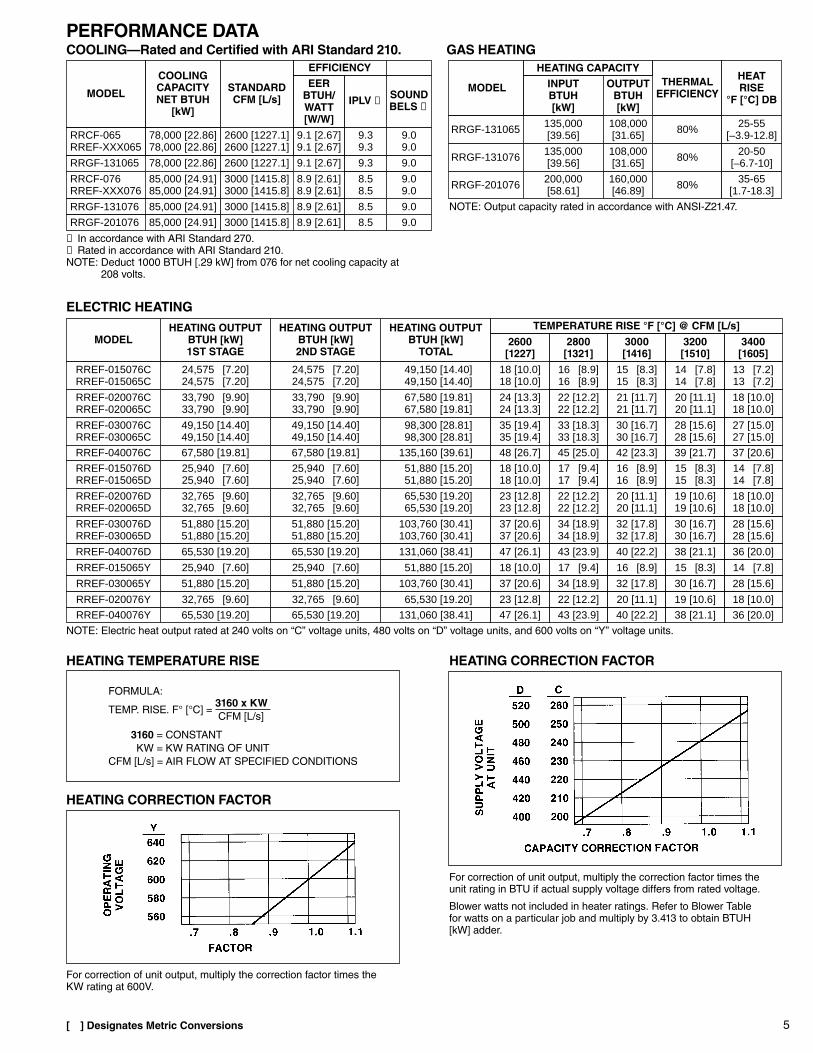
PERFORMANCE DATACOOLING—Rated and Certified with ARI Standard 210. GAS HEATING
[ ] Designates Metric Conversions
RRGF-131065 78,000 [22.86]
RRCF-076RREF-XXX076
85,000 [24.91]85,000 [24.91]
RRGF-131076 85,000 [24.91]
RRGF-201076 85,000 [24.91]
MODEL
COOLINGCAPACITYNET BTUH
[kW]
3000 [1415.8]
3000 [1415.8]
3000 [1415.8]3000 [1415.8]
2600 [1227.1]
STANDARDCFM [L/s]
9.1 [2.67]
8.9 [2.61]8.9 [2.61]
8.9 [2.61]
8.9 [2.61]
EFFICIENCY
8.5
8.5
8.58.5
9.3
9.0
9.0
9.09.0
9.0
9.1 [2.67]9.1 [2.67]
9.39.3
RRCF-065RREF-XXX065
78,000 [22.86]78,000 [22.86]
9.09.0
2600 [1227.1]2600 [1227.1]
EERBTUH/WATT[W/W]
IPLV ➁ SOUNDBELS ➀
MODELHEATING OUTPUT
BTUH [kW]TOTAL
HEATING OUTPUTBTUH [kW]1ST STAGE
RREF-020076CRREF-020065C
67,580 [19.81]67,580 [19.81]
33,790 [9.90]33,790 [9.90]
RREF-030076CRREF-030065C
98,300 [28.81]98,300 [28.81]
49,150 [14.40]49,150 [14.40]
35 [19.4]35 [19.4]
24 [13.3]24 [13.3]
TEMPERATURE RISE °F [°C] @ CFM [L/s]
49,150 [14.40]49,150 [14.40]
33,790 [9.90]33,790 [9.90]
HEATING OUTPUTBTUH [kW]2ND STAGE
33 [18.3]33 [18.3]
22 [12.2]22 [12.2]
30 [16.7]30 [16.7]
21 [11.7]21 [11.7]
28 [15.6]28 [15.6]
20 [11.1]20 [11.1]
27 [15.0]27 [15.0]
18 [10.0]18 [10.0]
45 [25.0]
17 [9.4]17 [9.4]
RREF-015076DRREF-015065D
51,880 [15.20]51,880 [15.20]
25,940 [7.60]25,940 [7.60]
RREF-040076C 135,160 [39.61]67,580 [19.81] 42 [23.3]48 [26.7]
18 [10.0]18 [10.0]
16 [8.9]16 [8.9]
39 [21.7]
15 [8.3]15 [8.3]
37 [20.6]
14 [7.8]14 [7.8]
67,580 [19.81]
25,940 [7.60]25,940 [7.60]
22 [12.2]22 [12.2]
RREF-020076DRREF-020065D
65,530 [19.20]65,530 [19.20]
32,765 [9.60]32,765 [9.60]
23 [12.8]23 [12.8]
20 [11.1]20 [11.1]
19 [10.6]19 [10.6]
18 [10.0]18 [10.0]
32,765 [9.60]32,765 [9.60]
34 [18.9]34 [18.9]
RREF-030076DRREF-030065D
103,760 [30.41]103,760 [30.41]
51,880 [15.20]51,880 [15.20]
37 [20.6]37 [20.6]
32 [17.8]32 [17.8]
30 [16.7]30 [16.7]
28 [15.6]28 [15.6]
51,880 [15.20]51,880 [15.20]
43 [23.9]RREF-040076D 131,060 [38.41]65,530 [19.20] 40 [22.2]47 [26.1] 38 [21.1] 36 [20.0]65,530 [19.20]
17 [9.4]RREF-015065Y 51,880 [15.20]25,940 [7.60] 16 [8.9]18 [10.0] 15 [8.3] 14 [7.8]25,940 [7.60]
34 [18.9]RREF-030065Y 103,760 [30.41]51,880 [15.20] 32 [17.8]37 [20.6] 30 [16.7] 28 [15.6]51,880 [15.20]
22 [12.2]RREF-020076Y 65,530 [19.20]32,765 [9.60] 20 [11.1]23 [12.8] 19 [10.6] 18 [10.0]32,765 [9.60]
43 [23.9]RREF-040076Y 131,060 [38.41]65,530 [19.20] 40 [22.2]47 [26.1] 38 [21.1] 36 [20.0]65,530 [19.20]
RREF-015076CRREF-015065C
49,150 [14.40]49,150 [14.40]
24,575 [7.20]24,575 [7.20]
16 [8.9]16 [8.9]
18 [10.0]18 [10.0]
15 [8.3]15 [8.3]
14 [7.8]14 [7.8]
13 [7.2]13 [7.2]
24,575 [7.20]24,575 [7.20]
2800[1321]
2600[1227]
3000[1416]
3200[1510]
3400[1605]
RRGF-131065 80%135,000[39.56]
RRGF-131076 80%135,000[39.56]
RRGF-201076 80%200,000[58.61]
35-65[1.7-18.3]
20-50[–6.7-10]
25-55[–3.9-12.8]
THERMALEFFICIENCY
HEATRISE
°F [°C] DBMODEL
HEATING CAPACITY
160,000[46.89]
108,000[31.65]
108,000[31.65]
INPUTBTUH[kW]
OUTPUTBTUH[kW]
➀ In accordance with ARI Standard 270.➁ Rated in accordance with ARI Standard 210.NOTE: Deduct 1000 BTUH [.29 kW] from 076 for net cooling capacity at
208 volts.
NOTE: Electric heat output rated at 240 volts on “C” voltage units, 480 volts on “D” voltage units, and 600 volts on “Y” voltage units.
NOTE: Output capacity rated in accordance with ANSI-Z21.47.
ELECTRIC HEATING
HEATING TEMPERATURE RISE HEATING CORRECTION FACTOR
HEATING CORRECTION FACTOR
For correction of unit output, multiply the correction factor times theunit rating in BTU if actual supply voltage differs from rated voltage.
Blower watts not included in heater ratings. Refer to Blower Tablefor watts on a particular job and multiply by 3.413 to obtain BTUH[kW] adder.
For correction of unit output, multiply the correction factor times theKW rating at 600V.
FORMULA:
TEMP. RISE. F° [°C] = 3160 x KWCFM [L/s]
3160 = CONSTANTKW = KW RATING OF UNIT
CFM [L/s] = AIR FLOW AT SPECIFIED CONDITIONS
6
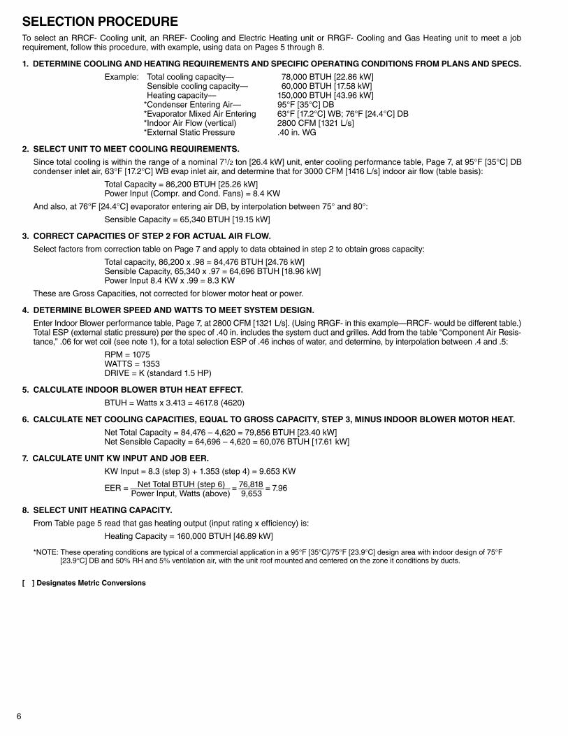
SELECTION PROCEDURETo select an RRCF- Cooling unit, an RREF- Cooling and Electric Heating unit or RRGF- Cooling and Gas Heating unit to meet a jobrequirement, follow this procedure, with example, using data on Pages 5 through 8.
1. DETERMINE COOLING AND HEATING REQUIREMENTS AND SPECIFIC OPERATING CONDITIONS FROM PLANS AND SPECS.
Example: *Total cooling capacity— 78,000 BTUH [22.86 kW]*Sensible cooling capacity— 60,000 BTUH [17.58 kW]*Heating capacity— 150,000 BTUH [43.96 kW]*Condenser Entering Air— 95°F [35°C] DB*Evaporator Mixed Air Entering 63°F [17.2°C] WB; 76°F [24.4°C] DB*Indoor Air Flow (vertical) 2800 CFM [1321 L/s]*External Static Pressure .40 in. WG
2. SELECT UNIT TO MEET COOLING REQUIREMENTS.
Since total cooling is within the range of a nominal 71/2 ton [26.4 kW] unit, enter cooling performance table, Page 7, at 95°F [35°C] DBcondenser inlet air, 63°F [17.2°C] WB evap inlet air, and determine that for 3000 CFM [1416 L/s] indoor air flow (table basis):
Total Capacity = 86,200 BTUH [25.26 kW]Power Input (Compr. and Cond. Fans) = 8.4 KW
And also, at 76°F [24.4°C] evaporator entering air DB, by interpolation between 75° and 80°:
Sensible Capacity = 65,340 BTUH [19.15 kW]
3. CORRECT CAPACITIES OF STEP 2 FOR ACTUAL AIR FLOW.
Select factors from correction table on Page 7 and apply to data obtained in step 2 to obtain gross capacity:
Total capacity, 86,200 x .98 = 84,476 BTUH [24.76 kW]Sensible Capacity, 65,340 x .97 = 64,696 BTUH [18.96 kW]Power Input 8.4 KW x .99 = 8.3 KW
These are Gross Capacities, not corrected for blower motor heat or power.
4. DETERMINE BLOWER SPEED AND WATTS TO MEET SYSTEM DESIGN.
Enter Indoor Blower performance table, Page 7, at 2800 CFM [1321 L/s]. (Using RRGF- in this example—RRCF- would be different table.)Total ESP (external static pressure) per the spec of .40 in. includes the system duct and grilles. Add from the table “Component Air Resis-tance,” .06 for wet coil (see note 1), for a total selection ESP of .46 inches of water, and determine, by interpolation between .4 and .5:
RPM = 1075WATTS = 1353DRIVE = K (standard 1.5 HP)
5. CALCULATE INDOOR BLOWER BTUH HEAT EFFECT.
BTUH = Watts x 3.413 = 4617.8 (4620)
6. CALCULATE NET COOLING CAPACITIES, EQUAL TO GROSS CAPACITY, STEP 3, MINUS INDOOR BLOWER MOTOR HEAT.
Net Total Capacity = 84,476 – 4,620 = 79,856 BTUH [23.40 kW]Net Sensible Capacity = 64,696 – 4,620 = 60,076 BTUH [17.61 kW]
7. CALCULATE UNIT KW INPUT AND JOB EER.
KW Input = 8.3 (step 3) + 1.353 (step 4) = 9.653 KW
EER = Net Total BTUH (step 6) = 76,818 = 7.96Power Input, Watts (above) 9,653
8. SELECT UNIT HEATING CAPACITY.
From Table page 5 read that gas heating output (input rating x efficiency) is:
Heating Capacity = 160,000 BTUH [46.89 kW]
*NOTE: These operating conditions are typical of a commercial application in a 95°F [35°C]/75°F [23.9°C] design area with indoor design of 75°F[23.9°C] DB and 50% RH and 5% ventilation air, with the unit roof mounted and centered on the zone it conditions by ducts.
[ ] Designates Metric Conversions
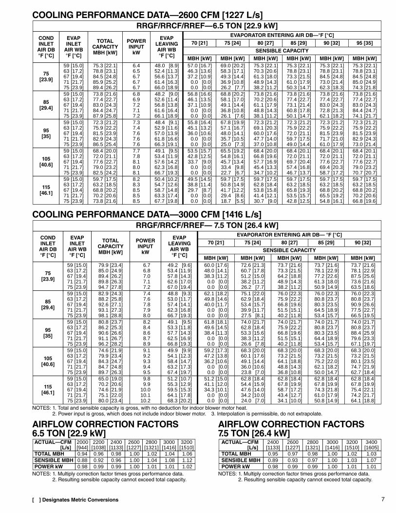
7
COOLING PERFORMANCE DATA—2600 CFM [1227 L/s]
COOLING PERFORMANCE DATA—3000 CFM [1416 L/s]
AIRFLOW CORRECTION FACTORS6.5 TON [22.9 kW]
AIRFLOW CORRECTION FACTORS7.5 TON [26.4 kW]
RRGF/RRCF/RREF—6.5 TON [22.9 kW]
POWERINPUT
kW
EVAPLEAVINGAIR WB°F [°C]
CONDINLET
AIR DB°F [°C]
EVAPINLET
AIR WB°F [°C]
EVAPORATOR ENTERING AIR DB—°F [°C]TOTAL
CAPACITYMBH [kW]
70 [21] 75 [24] 80 [27] 85 [29] 90 [32] 95 [35]
6.46.56.76.76.7
48.0 [8.9]52.4 [11.3]56.6 [13.7]61.4 [16.3]66.0 [18.9]
75[23.9]
59 [15.0]63 [17.2]67 [19.4]71 [21.7]75 [23.9]
57.0 [16.7]46.3 [13.6]37.2 [10.9]
0.0 [0.0]0.0 [0.0]
75.3 [22.1]78.8 [23.1]84.5 [24.8]85.9 [25.2]89.4 [26.2]
69.0 [20.2]58.3 [17.1]49.3 [14.4]36.9 [10.8]26.2 [7.7]
75.3 [22.1]70.3 [20.6]61.3 [18.0]48.9 [14.3]38.2 [11.2]
75.3 [22.1]78.8 [23.1]73.3 [21.5]61.0 [17.9]50.3 [14.7]
75.3 [22.1]78.8 [23.1]84.5 [24.8]73.0 [21.4]62.3 [18.3]
75.3 [22.1]78.8 [23.1]84.5 [24.8]85.0 [24.9]74.3 [21.8]
SENSIBLE CAPACITY
MBH [kW] MBH [kW] MBH [kW] MBH [kW] MBH [kW] MBH [kW]
6.86.97.27.17.2
48.2 [9.0]52.6 [11.4]56.8 [13.8]61.6 [16.4]66.1 [18.9]
85[29.4]
59 [15.0]63 [17.2]67 [19.4]71 [21.7]75 [23.9]
56.8 [16.6]46.1 [13.5]37.1 [10.9]
0.0 [0.0]0.0 [0.0]
73.8 [21.6]77.4 [22.7]83.0 [24.3]84.4 [24.7]87.9 [25.8]
68.8 [20.2]58.1 [17.0]49.1 [14.4]36.8 [10.8]26.1 [7.6]
73.8 [21.6]70.2 [20.6]61.1 [17.9]48.8 [14.3]38.1 [11.2]
73.8 [21.6]77.4 [22.7]73.1 [21.4]60.8 [17.8]50.1 [14.7]
73.8 [21.6]77.4 [22.7]83.0 [24.3]72.8 [21.3]62.1 [18.2]
73.8 [21.6]77.4 [22.7]83.0 [24.3]84.4 [24.7]74.1 [21.7]
7.77.88.18.08.1
49.1 [9.5]53.4 [11.9]57.6 [14.2]62.3 [16.8]66.7 [19.3]
105[40.6]
59 [15.0]63 [17.2]67 [19.4]71 [21.7]75 [23.9]
53.5 [15.7]42.8 [12.5]33.7 [9.0]
0.0 [0.0]0.0 [0.0]
68.4 [20.0]72.0 [21.1]77.6 [22.7]79.0 [23.2]82.5 [24.2]
65.5 [19.2]54.8 [16.1]45.7 [13.4]33.4 [9.8]22.7 [6.7]
68.4 [20.0]66.8 [19.6]57.7 [16.9]45.4 [13.3]34.7 [10.2]
68.4 [20.1]72.0 [21.1]69.7 [20.4]57.4 [16.8]46.7 [13.7]
68.4 [20.1]72.0 [21.1]77.6 [22.7]69.4 [20.3]58.7 [17.2]
68.4 [20.1]72.0 [21.1]77.6 [22.7]79.0 [23.2]70.7 [20.7]
7.37.47.67.67.6
48.4 [9.1]52.9 [11.6]57.0 [13.9]61.8 [16.6]66.3 [19.1]
95[35]
59 [15.0]63 [17.2]67 [19.4]71 [21.7]75 [23.9]
55.8 [16.4]45.1 [13.2]36.0 [10.6]
0.0 [0.0]0.0 [0.0]
72.3 [21.2]75.9 [22.2]81.5 [23.9]82.9 [24.3]86.5 [25.4]
67.8 [19.9]57.1 [16.7]48.0 [14.1]35.7 [10.5]25.0 [7.3]
72.3 [21.2]69.1 [20.3]60.0 [17.6]47.7 [14.0]37.0 [10.8]
72.3 [21.2]75.9 [22.2]72.0 [21.1]59.7 [17.5]49.0 [14.4]
72.3 [21.2]75.9 [22.2]81.5 [23.9]71.7 [21.0]61.0 [17.9]
72.3 [21.2]75.9 [22.2]81.5 [23.9]82.9 [24.3]73.0 [21.4]
8.28.38.58.58.5
50.4 [10.2]54.7 [12.6]58.7 [14.8]63.3 [17.4]67.7 [19.8]
115[46.1]
59 [15.0]63 [17.2]67 [19.4]71 [21.7]75 [23.9]
49.5 [14.5]38.8 [11.4]29.7 [8.7]
0.0 [0.0]0.0 [0.0]
59.7 [17.5]63.2 [18.5]68.8 [20.2]70.2 [20.6]73.8 [21.6]
59.7 [17.5]50.8 [14.9]41.7 [12.2]29.4 [8.6]18.7 [5.5]
59.7 [17.5]62.8 [18.4]53.8 [15.8]41.4 [12.1]30.7 [9.0]
59.7 [17.5]63.2 [18.5]65.8 [19.3]53.5 [15.7]42.8 [12.5]
59.7 [17.5]63.2 [18.5]68.8 [20.2]65.5 [19.2]54.8 [16.1]
59.7 [17.5]63.2 [18.5]68.8 [20.2]70.2 [20.6]66.8 [19.6]
8.28.48.68.78.9
49.1 [9.5]53.3 [11.8]57.7 [14.3]62.5 [16.9]66.8 [19.3]
95[35]
59 [15.0]63 [17.2]67 [19.4]71 [21.7]75 [23.9]
61.8 [18.1]49.6 [14.5]38.4 [11.3]
0.0 [0.0]0.0 [0.0]
80.8 [23.7]86.2 [25.3]90.6 [26.6]91.1 [26.7]96.2 [28.2]
74.0 [21.7]62.8 [18.4]53.3 [15.6]38.3 [11.2]26.6 [7.8]
74.0 [21.7]75.9 [22.2]66.8 [19.6]51.5 [15.1]40.2 [11.8]
74.0 [21.7]80.8 [23.7]80.3 [23.5]64.4 [18.9]53.4 [15.7]
74.0 [21.7]80.8 [23.7]88.4 [25.9]79.6 [23.3]67.1 [19.7]
9.89.9
10.010.110.2
51.2 [10.7]55.3 [12.9]59.5 [15.3]64.1 [17.8]68.3 [20.2]
115[46.1]
59 [15.0]63 [17.2]67 [19.4]71 [21.7]75 [23.9]
51.2 [15.0]41.1 [12.0]34.3 [10.1]
0.0 [0.0]0.0 [0.0]
65.0 [19.0]70.2 [20.6]74.6 [21.9]75.1 [22.0]80.0 [23.4]
62.8 [18.4]54.4 [15.9]47.6 [14.0]34.2 [10.0]24.0 [7.0]
62.8 [18.4]67.8 [19.9]58.7 [17.2]43.4 [12.7]34.1 [10.0]
62.8 [18.4]67.8 [19.9]74.3 [21.8]61.0 [17.9]50.8 [14.9]
62.8 [18.4]67.8 [19.9]75.4 [22.1]74.2 [21.7]64.1 [18.8]
9.19.29.39.49.5
49.9 [9.9]54.1 [12.3]58.4 [14.7]63.2 [17.3]67.4 [19.7]
105[40.6]
59 [15.0]63 [17.2]67 [19.4]71 [21.7]75 [23.9]
59.2 [17.3]47.2 [13.8]36.2 [10.6]
0.0 [0.0]0.0 [0.0]
74.6 [21.9]79.9 [23.4]84.3 [24.7]84.7 [24.8]89.7 [26.3]
68.3 [20.0]60.1 [17.6]49.1 [14.4]36.0 [10.6]23.8 [7.0]
68.3 [20.0]73.2 [21.5]64.1 [18.8]48.8 [14.3]36.8 [10.8]
68.3 [20.0]73.2 [21.5]75.2 [22.0]62.1 [18.2]50.0 [14.7]
68.3 [20.0]73.2 [21.5]80.1 [23.5]74.7 [21.9]62.7 [18.4]
RRGF/RRCF/RREF— 7.5 TON [26.4 kW]
7.47.67.87.98.0
48.8 [9.3]53.0 [11.7]57.4 [14.1]62.3 [16.8]66.7 [19.3]
85[29.4]
59 [15.0]63 [17.2]67 [19.4]71 [21.7]75 [23.9]
62.1 [18.2]49.8 [14.6]40.0 [11.7]
0.0 [0.0]0.0 [0.0]
82.9 [24.3]88.2 [25.8]92.6 [27.1]93.1 [27.3]98.1 [28.8]
75.1 [22.0]62.9 [18.4]53.4 [15.7]39.9 [11.7]27.5 [8.1]
76.0 [22.3]75.9 [22.2]66.8 [19.6]51.5 [15.1]40.2 [11.8]
76.0 [22.3]80.8 [23.7]80.3 [23.5]64.5 [18.9]53.4 [15.7]
76.0 [22.3]80.8 [23.7]90.9 [26.6]77.5 [22.7]66.5 [19.5]
POWERINPUT
kW
EVAPLEAVINGAIR WB°F [°C]
CONDINLET
AIR DB°F [°C]
EVAPINLET
AIR WB°F [°C]
EVAPORATOR ENTERING AIR DB— °F [°C]TOTAL
CAPACITYMBH [kW]
70 [21] 75 [24] 80 [27] 85 [29] 90 [32]
MBH [kW] MBH [kW] MBH [kW] MBH [kW] MBH [kW]
SENSIBLE CAPACITY
6.76.87.07.17.2
49.2 [9.6]53.4 [11.9]57.8 [14.3]62.6 [17.0]67.0 [19.4]
75[23.9]
59 [15.0]63 [17.2]67 [19.4]71 [21.7]75 [23.9]
60.0 [17.6]48.0 [14.1]38.3 [11.2]
0.0 [0.0]0.0 [0.0]
79.9 [23.4]85.0 [24.9]89.4 [26.2]89.8 [26.3]94.7 [27.8]
72.6 [21.3]60.7 [17.8]51.2 [15.0]38.2 [11.2]26.2 [7.7]
73.7 [21.6]73.3 [21.5]64.2 [18.8]48.9 [14.3]38.2 [11.2]
73.7 [21.6]78.1 [22.9]77.2 [22.6]61.3 [18.0]50.9 [14.9]
73.7 [21.6]78.1 [22.9]87.5 [25.6]73.6 [21.6]63.5 [18.6]
0.98TOTAL MBH 0.94 0.96
0.99POWER kW 0.98 0.990.96SENSIBLE MBH 0.88 0.92
2400[1133]
ACTUAL—CFM[L/s]
2000[944]
2200[1038]
1.00
1.001.00
2600[1227]
1.02 1.04
1.011.08
3000[1416]
1.011.04
2800[1321]
1.06
1.021.12
3200[1510]
0.98 1.00TOTAL MBH 0.95
1.00
0.971.00
3000[1416]
1.02 1.03
1.010.991.07
3400[1605]
POWER kW 0.98 1.010.991.03
3200[1510]
0.97SENSIBLE MBH 0.89 0.93
2800[1321]
ACTUAL—CFM[L/s]
2400[1133]
2600[1227]
NOTES: 1. Total and sensible capacity is gross, with no deduction for indoor blower motor heat.2. Power input is gross, which does not include indoor blower motor. 3. Interpolation is permissible, do not extrapolate.
NOTES: 1. Multiply correction factor times gross performance data.2. Resulting sensible capacity cannot exceed total capacity.
NOTES: 1. Multiply correction factor times gross performance data.2. Resulting sensible capacity cannot exceed total capacity.
[ ] Designates Metric Conversions
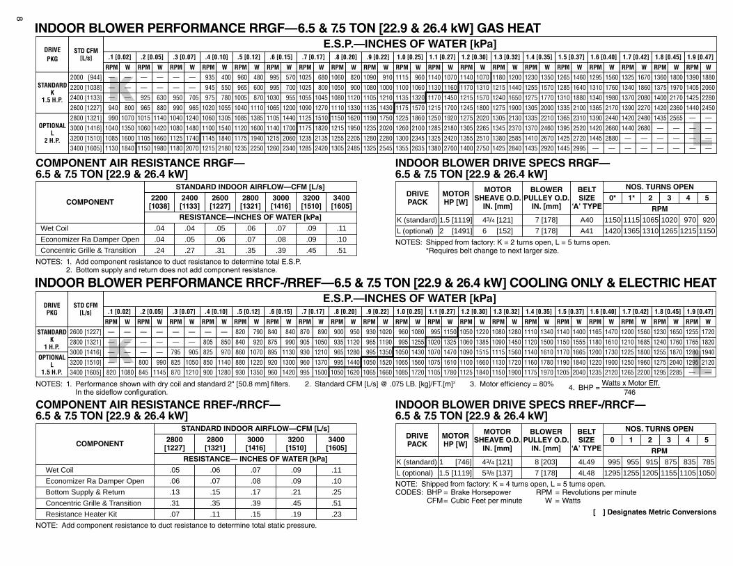
8
INDOOR BLOWER PERFORMANCE RRGF—6.5 & 7.5 TON [22.9 & 26.4 kW] GAS HEAT
[ ] Designates Metric Conversions
NOTES: 1. Add component resistance to duct resistance to determine total E.S.P.2. Bottom supply and return does not add component resistance.
NOTES: 1. Performance shown with dry coil and standard 2" [50.8 mm] filters. 2. Standard CFM [L/s] @ .075 LB. [kg]/FT.[m]3 3. Motor efficiency = 80% 4. BHP = Watts x Motor Eff.
746In the sideflow configuration.
NOTES: Shipped from factory: K = 2 turns open, L = 5 turns open.*Requires belt change to next larger size.
NOTE: Shipped from factory: K = 4 turns open, L = 5 turns open.CODES: BHP = Brake Horsepower RPM = Revolutions per minute
CFM= Cubic Feet per minute W = Watts
NOTE: Add component resistance to duct resistance to determine total static pressure.
COMPONENT AIR RESISTANCE RRGF—6.5 & 7.5 TON [22.9 & 26.4 kW]
INDOOR BLOWER DRIVE SPECS RRGF—6.5 & 7.5 TON [22.9 & 26.4 kW]
COMPONENT AIR RESISTANCE RREF-/RRCF—6.5 & 7.5 TON [22.9 & 26.4 kW]
INDOOR BLOWER DRIVE SPECS RREF-/RRCF—6.5 & 7.5 TON [22.9 & 26.4 kW]
INDOOR BLOWER PERFORMANCE RRCF-/RREF—6.5 & 7.5 TON [22.9 & 26.4 kW] COOLING ONLY & ELECTRIC HEAT
LK
DRIVEPKG
STD CFM[L/s]
E.S.P.—INCHES OF WATER [kPa].1 [0.02] .2 [0.05] .3 [0.07] .4 [0.10]
RPM W RPM W RPM W RPM W
2600 [1227] 940 800 965 880 990 965 1020 1055
2800 [1321] 990 1070 1015 1140 1040 1240 1060 1305
3000 [1416] 1040 1350 1060 1420 1080 1480 1100 1540
3200 [1510] 1085 1600 1105 1660 1125 1740 1145 1840
3400 [1605] 1130 1840 1150 1980 1180 2070 1215 2180
.5 [0.12] .6 [0.15] .7 [0.17] .8 [0.20]
RPM W RPM W RPM W RPM W
1040 1110 1065 1200 1090 1270 1110 1330
1085 1385 1105 1440 1125 1510 1150 1620
1120 1600 1140 1700 1175 1820 1215 1950
1175 1940 1215 2060 1235 2135 1255 2205
1235 2250 1260 2340 1285 2420 1305 2485
1.3 [0.32] 1.4 [0.35] 1.5 [0.37] 1.6 [0.40]
RPM W RPM W RPM W RPM W
1275 1900 1305 2000 1335 2100 1365 2170
1305 2130 1335 2210 1365 2310 1390 2440
1345 2370 1370 2460 1395 2520 1420 2660
1380 2585 1410 2670 1425 2720 1445 2880
1425 2840 1435 2920 1445 2995 — —
.9 [0.22] 1.0 [0.25] 1.1 [0.27] 1.2 [0.30]
RPM W RPM W RPM W RPM W
1135 1430 1175 1570 1215 1700 1245 1800
1190 1750 1225 1860 1250 1920 1275 2020
1235 2020 1260 2100 1285 2180 1305 2265
1280 2280 1300 2345 1325 2420 1355 2510
1325 2545 1355 2635 1380 2700 1400 2750
1.7 [0.42] 1.8 [0.45] 1.9 [0.47]
RPM W RPM W RPM W
1390 2270 1420 2360 1440 2450
1420 2480 1435 2565 — —
1440 2680 — — — —
— — — — — —
— — — — — —
OPTIONALL
2 H.P.
960 480 995 570 1025 680 1060 820
965 600 995 700 1025 800 1050 900
1005 870 1030 955 1055 1045 1080 1120
1180 1200 1230 1350 1265 1460 1295 1560
1215 1440 1255 1570 1285 1640 1310 1760
1240 1650 1275 1770 1310 1880 1340 1980
STANDARDK
1.5 H.P.
2000 [944] — — — — — — 935 400 1090 910 1115 960 1140 1070 1140
2200 [1038] — — — — — — 945 550
1070
1080 1000 1100 1060 1130 1160 1170 1310
1105 1210 1135 1320 1170 1450 1215 15702400 [1133] — — 925 630 950 705 975 780
1325 1670 1360 1800 1390 1880
1340 1860 1375 1970 1405 2060
1370 2080 1400 2170 1425 2280
RESISTANCE—INCHES OF WATER [kPa]
Economizer Ra Damper Open .04
Concentric Grille & Transition .24
COMPONENT
STANDARD INDOOR AIRFLOW—CFM [L/s]2200
[1038]2400[1133]
.27
.05 .06
.31
2600[1227]
2800[1321]
.35
.07 .09
.45
3200[1510]
3400[1605]
.51
.10
3000[1416]
.39
.08
.05 .06Wet Coil .04 .09 .11.07.04
Wet Coil .07.05 .09.06 .11
COMPONENT
STANDARD INDOOR AIRFLOW—CFM [L/s]2800
[1227]2800
[1321]3000[1416]
3200[1510]
3400[1605]
RESISTANCE— INCHES OF WATER [kPa]
Economizer Ra Damper Open .06 .07 .08 .09 .10
Bottom Supply & Return .13 .15 .17 .21 .25
Concentric Grille & Transition .31 .35 .39 .45 .51
Resistance Heater Kit .07 .11 .15 .19 .23
MOTORHP [W]
MOTORSHEAVE O.D.
IN. [mm]
DRIVEPACK
BLOWERPULLEY O.D.
IN. [mm]
BELTSIZE
‘A’ TYPE
NOS. TURNS OPEN50* 1* 2 3 4
9207 [178] A401.5 [1119] 43/4 [121]K (standard) 1150 1115 1065 1020 970
RPM
11507 [178] A412.5 [1491] 63/4 [152]L (optional) 1420 1365 1310 1265 1215
5
10507 [178] 4L481.5 [1119] 53/8 [137]
0 1 2 3 4
785
L (optional)
8 [203] 4L491.5 [746] 43/4 [121]
BLOWERPULLEY O.D.
IN. [mm]
K (standard) 995 955
BELTSIZE
‘A’ TYPE
915 875 835
MOTORHP [W]
MOTORSHEAVE O.D.
IN. [mm]
DRIVEPACK
1295
NOS. TURNS OPEN
1255 1205 1155 1105
RPM
K L
.5 [0.12] .6 [0.15] .7 [0.17] .8 [0.20]
RPM W RPM W RPM W RPM W
820 790 840 840 870 890 900 950
840 920 875 990 905 1050 935 1120
860 1070 895 1130 930 1210 965 1280
880 1220 920 1300 960 1370 995 1440
930 1350 960 1420 995 1500 1050 1620
1.3 [0.32] 1.4 [0.35] 1.5 [0.37] 1.6 [0.40]
RPM W RPM W RPM W RPM W
1080 1280 1110 1340 1140 1400 1165 1470
1090 1450 1120 1500 1150 1555
DRIVEPKG
STD CFM[L/s]
E.S.P.—INCHES OF WATER [kPa]
1180 1610
1115 1560 1140 1610 1170 1665 1200 1730
1130 1720 1160 1780 1190 1840 1220 1900
1150 1900 1175 1970 1205 2040 1235 2120
.1 [0.02] .2 [0.05] .3 [0.07] .4 [0.10] .9 [0.22] 1.0 [0.25] 1.1 [0.27] 1.2 [0.30]
RPM W RPM W RPM W RPM W
930 1020 960 1080 995 1150 1050 1220
965 1190 995 1255 1020 1325 1060 1385
RPM W RPM W RPM W RPM W
995 1350 1050 1430 1070 1470 1090 1515
1050 1520 1065 1560 1075 1610 1100 1660
1065 1660 1085 1720 1105 1780 1125 1840
2600 [1227] — — — — — — — —
1.7 [0.42] 1.8 [0.45] 1.9 [0.47]
RPM W RPM W RPM W
1200 1560 1230 1650 1255 1720
2800 [1321] — — — — — — 805 850 1210 1685 1240 1760 1765 1820
1225 1800 1255 1870 1280 1940
1250 1960 1275 2040 1295 2120
1265 2200 1295 2285 — —
3000 [1416] — — — — 795 905 825 970
3200 [1510] — — 800 990 825 1050 850 1140
3400 [1605] 820 1080 845 1145 870 1210 900 1280
STANDARDK
1 H.P.
OPTIONALL
1.5 H.P.
9[ ] Designates Metric Conversions
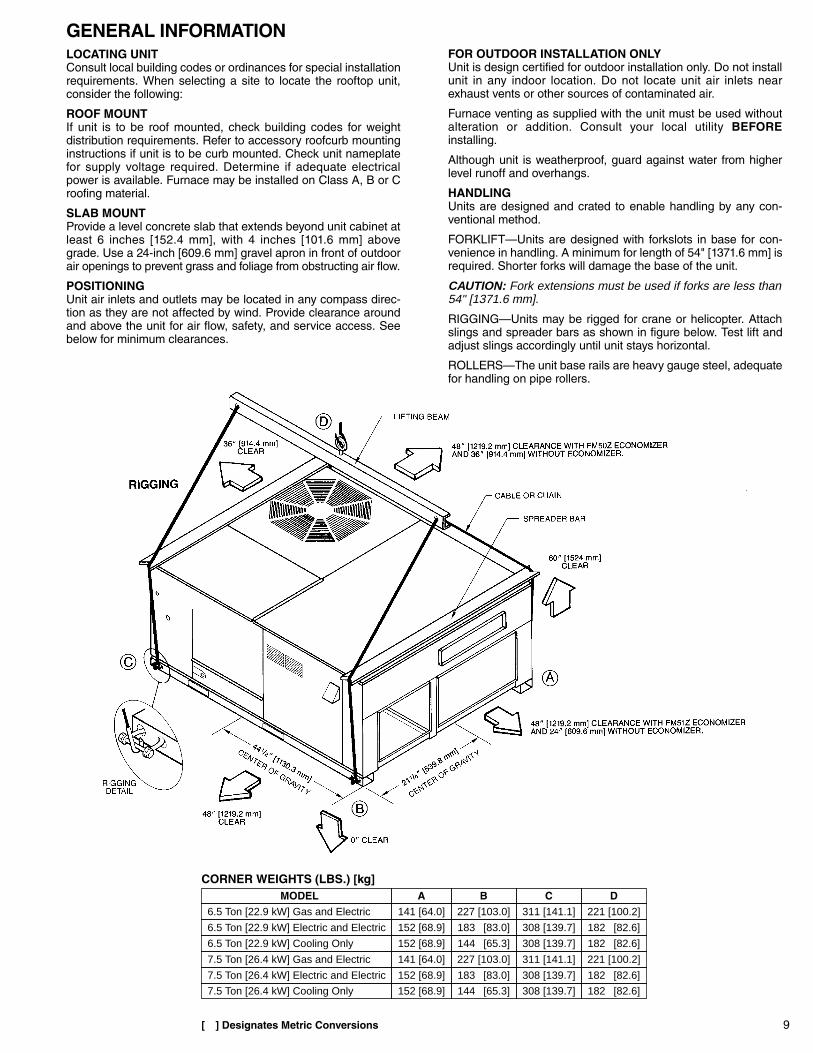
GENERAL INFORMATIONLOCATING UNITConsult local building codes or ordinances for special installationrequirements. When selecting a site to locate the rooftop unit,consider the following:
ROOF MOUNTIf unit is to be roof mounted, check building codes for weightdistribution requirements. Refer to accessory roofcurb mountinginstructions if unit is to be curb mounted. Check unit nameplatefor supply voltage required. Determine if adequate electricalpower is available. Furnace may be installed on Class A, B or Croofing material.
SLAB MOUNTProvide a level concrete slab that extends beyond unit cabinet atleast 6 inches [152.4 mm], with 4 inches [101.6 mm] abovegrade. Use a 24-inch [609.6 mm] gravel apron in front of outdoorair openings to prevent grass and foliage from obstructing air flow.
POSITIONINGUnit air inlets and outlets may be located in any compass direc-tion as they are not affected by wind. Provide clearance aroundand above the unit for air flow, safety, and service access. Seebelow for minimum clearances.
FOR OUTDOOR INSTALLATION ONLYUnit is design certified for outdoor installation only. Do not installunit in any indoor location. Do not locate unit air inlets nearexhaust vents or other sources of contaminated air.
Furnace venting as supplied with the unit must be used withoutalteration or addition. Consult your local utility BEFOREinstalling.
Although unit is weatherproof, guard against water from higherlevel runoff and overhangs.
HANDLINGUnits are designed and crated to enable handling by any con-ventional method.
FORKLIFT—Units are designed with forkslots in base for con-venience in handling. A minimum for length of 54" [1371.6 mm] isrequired. Shorter forks will damage the base of the unit.
CAUTION: Fork extensions must be used if forks are less than54" [1371.6 mm].
RIGGING—Units may be rigged for crane or helicopter. Attachslings and spreader bars as shown in figure below. Test lift andadjust slings accordingly until unit stays horizontal.
ROLLERS—The unit base rails are heavy gauge steel, adequatefor handling on pipe rollers.
CORNER WEIGHTS (LBS.) [kg]MODEL A B C D
6.5 Ton [22.9 kW] Gas and Electric 141 [64.0] 227 [103.0] 311 [141.1] 221 [100.2]
6.5 Ton [22.9 kW] Electric and Electric 152 [68.9] 183 [83.0] 308 [139.7] 182 [82.6]
6.5 Ton [22.9 kW] Cooling Only 152 [68.9] 144 [65.3] 308 [139.7] 182 [82.6]
7.5 Ton [26.4 kW] Gas and Electric 141 [64.0] 227 [103.0] 311 [141.1] 221 [100.2]
7.5 Ton [26.4 kW] Electric and Electric 152 [68.9] 183 [83.0] 308 [139.7] 182 [82.6]
7.5 Ton [26.4 kW] Cooling Only 152 [68.9] 144 [65.3] 308 [139.7] 182 [82.6]
10
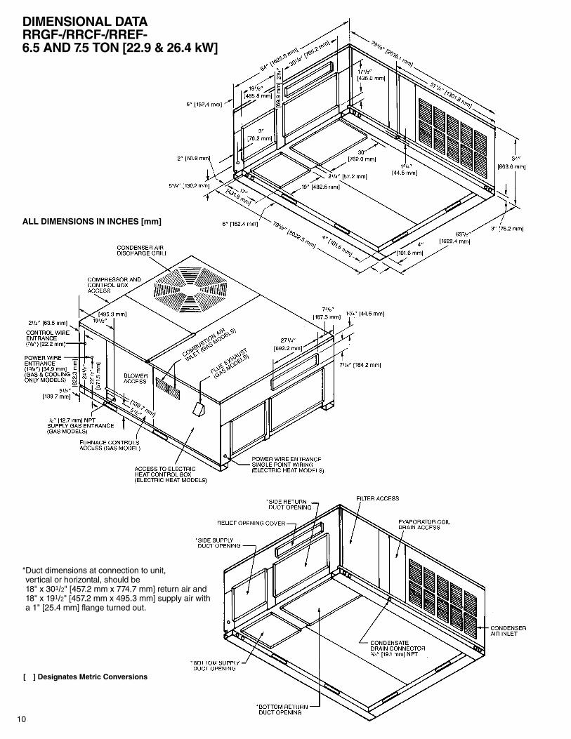
DIMENSIONAL DATARRGF-/RRCF-/RREF-6.5 AND 7.5 TON [22.9 & 26.4 kW]
ALL DIMENSIONS IN INCHES [mm]
[ ] Designates Metric Conversions
*Duct dimensions at connection to unit,vertical or horizontal, should be18" x 301/2" [457.2 mm x 774.7 mm] return air and18" x 191/2" [457.2 mm x 495.3 mm] supply air witha 1" [25.4 mm] flange turned out.
11
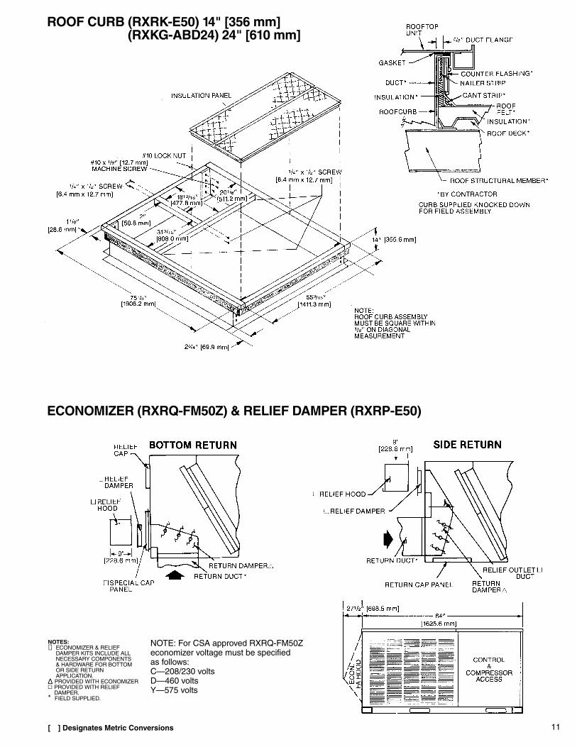
ROOF CURB (RXRK-E50) 14" [356 mm](RXKG-ABD24) 24" [610 mm]
ECONOMIZER (RXRQ-FM50Z) & RELIEF DAMPER (RXRP-E50)
[ ] Designates Metric Conversions
NOTES:➀ ECONOMIZER & RELIEF
DAMPER KITS INCLUDE ALLNECESSARY COMPONENTS& HARDWARE FOR BOTTOMOR SIDE RETURNAPPLICATION.
∆ PROVIDED WITH ECONOMIZER▫ PROVIDED WITH RELIEF
DAMPER.* FIELD SUPPLIED.
NOTE: For CSA approved RXRQ-FM50Zeconomizer voltage must be specified as follows:C—208/230 voltsD—460 voltsY—575 volts
12
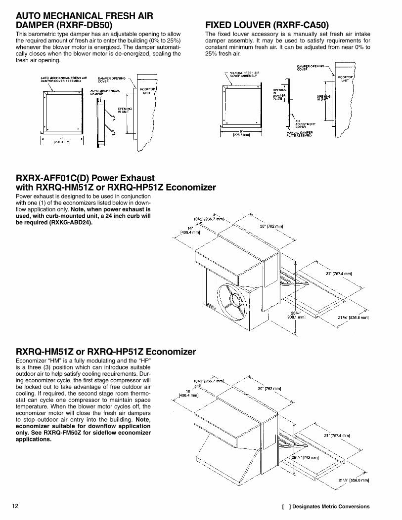
FIXED LOUVER (RXRF-CA50)The fixed louver accessory is a manually set fresh air intakedamper assembly. It may be used to satisfy requirements forconstant minimum fresh air. It can be adjusted from near 0% to25% fresh air.
AUTO MECHANICAL FRESH AIRDAMPER (RXRF-DB50)This barometric type damper has an adjustable opening to allowthe required amount of fresh air to enter the building (0% to 25%)whenever the blower motor is energized. The damper automati-cally closes when the blower motor is de-energized, sealing thefresh air opening.
RXRX-AFF01C(D) Power Exhaustwith RXRQ-HM51Z or RXRQ-HP51Z EconomizerPower exhaust is designed to be used in conjunctionwith one (1) of the economizers listed below in down-flow application only. Note, when power exhaust isused, with curb-mounted unit, a 24 inch curb willbe required (RXKG-ABD24).
RXRQ-HM51Z or RXRQ-HP51Z EconomizerEconomizer “HM” is a fully modulating and the “HP”is a three (3) position which can introduce suitableoutdoor air to help satisfy cooling requirements. Dur-ing economizer cycle, the first stage compressor willbe locked out to take advantage of free outdoor aircooling. If required, the second stage room thermo-stat can cycle one compressor to maintain spacetemperature. When the blower motor cycles off, theeconomizer motor will close the fresh air dampers to stop outdoor air entry into the building. Note,economizer suitable for downflow applicationonly. See RXRQ-FM50Z for sideflow economizerapplications.
[ ] Designates Metric Conversions
13
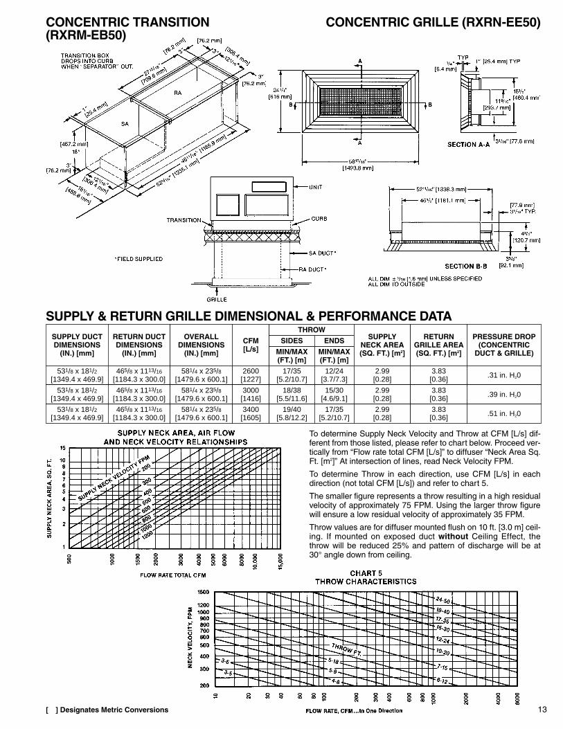
CONCENTRIC TRANSITION(RXRM-EB50)
SUPPLY & RETURN GRILLE DIMENSIONAL & PERFORMANCE DATA
CONCENTRIC GRILLE (RXRN-EE50)
[ ] Designates Metric Conversions
To determine Supply Neck Velocity and Throw at CFM [L/s] dif-ferent from those listed, please refer to chart below. Proceed ver-tically from “Flow rate total CFM [L/s]” to diffuser “Neck Area Sq.Ft. [m2]” At intersection of lines, read Neck Velocity FPM.
To determine Throw in each direction, use CFM [L/s] in eachdirection (not total CFM [L/s]) and refer to chart 5.
The smaller figure represents a throw resulting in a high residualvelocity of approximately 75 FPM. Using the larger throw figurewill ensure a low residual velocity of approximately 35 FPM.
Throw values are for diffuser mounted flush on 10 ft. [3.0 m] ceil-ing. If mounted on exposed duct without Ceiling Effect, thethrow will be reduced 25% and pattern of discharge will be at30° angle down from ceiling.
SUPPLY DUCTDIMENSIONS
(IN.) [mm]
CFM[L/s]
RETURN DUCTDIMENSIONS
(IN.) [mm] MIN/MAX(FT.) [m]
SIDESTHROW
MIN/MAX(FT.) [m]
ENDSOVERALLDIMENSIONS
(IN.) [mm]
SUPPLYNECK AREA(SQ. FT.) [m2]
RETURNGRILLE AREA(SQ. FT.) [m2]
PRESSURE DROP(CONCENTRIC
DUCT & GRILLE)
531/8 x 181/2[1349.4 x 469.9]
465/8 x 1113/16
[1184.3 x 300.0]581/4 x 235/8
[1479.6 x 600.1]2600
[1227]17/35
[5.2/10.7]12/24
[3.7/7.3]2.99
[0.28]3.83[0.36] .31 in. H20
531/8 x 181/2[1349.4 x 469.9]
465/8 x 1113/16
[1184.3 x 300.0]581/4 x 235/8
[1479.6 x 600.1]3000[1416]
18/38[5.5/11.6]
15/30[4.6/9.1]
2.99[0.28]
3.83[0.36] .39 in. H20
531/8 x 181/2[1349.4 x 469.9]
465/8 x 1113/16
[1184.3 x 300.0]581/4 x 235/8
[1479.6 x 600.1]3400[1605]
19/40[5.8/12.2]
17/35[5.2/10.7]
2.99[0.28]
3.83[0.36] .51 in. H20
14
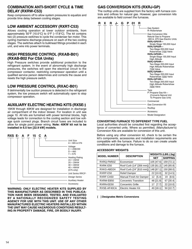
COMBINATION ANTI-SHORT CYCLE & TIMEDELAY (RXRW-C53)Keep compressors off to allow system pressures to equalize andprovide time delay between cooling stages.
LOW AMBIENT ACCESSORY (RXRT-C53)Allows cooling operation at lower outdoor ambients, fromapproximately 50°F [10.0°C] to 0°F [–17.8°C]. The kit containstwo (2) pressure switches to cycle the condenser fan motor. Thiscycling maintains discharge pressure on each of the two coolingstages. The switches attach to bulkhead fittings provided in eachunit, and wire into power terminals.
HIGH PRESSURE CONTROL (RXAB-B01)(RXAB-B02 For CSA Units)High Pressure switches provide additional protection to therefrigerant system. In the event of abnormally high dischargepressures, the switches will open the electrical circuit to thecompressor contactor, restricting compressor operation until aqualified service person determines and corrects the cause andresets the high pressure switch.
LOW PRESSURE CONTROL (RXAC-B01)If detrimentally low suction pressure is detected in the refrigerantsystem, the low pressure switch will automatically open to stopcompressor operation.
AUXILIARY ELECTRIC HEATING KITS (RXSE-)15KW through 40KW are designed for installation in dischargeair compartment of the indoor blower. For location in unit seepage 10. All kits are furnished with power terminal blocks, highvoltage leads for connection to the cooling section and low volt-age quick connect plugs. Branch circuit fuses are included toallow for single point power wiring. Note: 40KW kit not to beinstalled in 6.5 ton [22.9 kW] models.
GAS CONVERSION KITS (RXRJ-GP)The rooftop units are supplied from the factory with furnace con-trols and orifices for natural gas. However, gas conversion kitsare available to field convert the furnaces.
RXS E- A F 15 C AUnit SizeA = 065 & 076
VoltageC = 208/230D = 460Y = 575
Heating Rating15 = 15KW20 = 20KW30 = 30KW40 = 40KW(075 only)
Unit Series RRCF-
Design Series
Auxiliary Heater
Accessory
WARNING: ONLY ELECTRIC HEATER KITS SUPPLIED BYTHIS MANUFACTURER AS DESCRIBED IN THIS PUBLICA-TION HAVE BEEN DESIGNED, TESTED, AND EVALUATEDBY A NATIONALLY RECOGNIZED SAFETY TESTINGAGENCY FOR USE WITH THIS UNIT. USE OF ANY OTHERMANUFACTURED ELECTRIC HEATERS INSTALLED WITHINTHE UNIT MAY CAUSE HAZARDOUS CONDITIONS RESULT-ING IN PROPERTY DAMAGE, FIRE, OR BODILY INJURY.
R X R J- G P 01 RGas SystemR–Robertshaw
Gas Conversion KitsNatural Gas to Propane-065 & -075 Gas Electric UnitsRXRJ-GP01R—
Single Stage 135,000 InputRXRJ-GP02R—
Two-Stage 200,000 InputRobertshaw 7100 Valve
RXRJ-GP03R—Single-Stage 135,000 InputHigh Altitude
RXRJ-GP04R—Two-Stage 200,000 InputHigh Altitude Robertshaw7100 Valve
RXRJ-GP09R—Two-Stage 200,000 InputRobertshaw 7200 Valve
RXRJ-GP10R—Two-Stage 200,000 InputHigh Altitude Robertshaw7200 Valve
TypeP–Propane Gas Kit—
(Converts Natural UnitTo Propane Gas Unit)
Commercial
Gas Conversion Kit
Rooftop
Accessory
Model Designation
CONVERTING FURNACE TO DIFFERENT TYPE FUELLocal authorities should be consulted first regarding the accep-tance of converted units. Where so permitted, (Manufacturer’s)Conversion Kits are available for conversion of this unit.
Before using any other conversion kit, check to be certain thekit’s components, accessories and installation requirements arecompatible with the furnace. Failure to do so can create unsafeconditions and damage to the furnace.
ACCESSORY WEIGHTS
[ ] Designates Metric Conversions
MODEL NUMBER DESCRIPTIONSHIPPING
RXRQ-FM50Z 159 [72.1]Economizer 105 [47.6]
NETWEIGHTS (LBS.) [kg]
RXRK-E50 Roof Curb (14" [356 mm]) 135 [61.2] 145 [65.8]
RXRP-E50 Relief Damper 22 [10.0] 32 [14.5]
RXRF-CA50 Manual Fresh Air Damper 12 [5.4] 19 [8.6]
RXRM-EB50 Concentric Transition 48 [21.8] 67 [30.4]
RXRN-EE50 Concentric Grille 17 [7.7] 22 [10.0]
RXSE-AF40CA Electric Heater Kit 40 [18.1] 50 [22.7]
RXKG-ABD24 Roof Curb (24" [610 mm]) 148 [67.1] 150 [68.0]
15
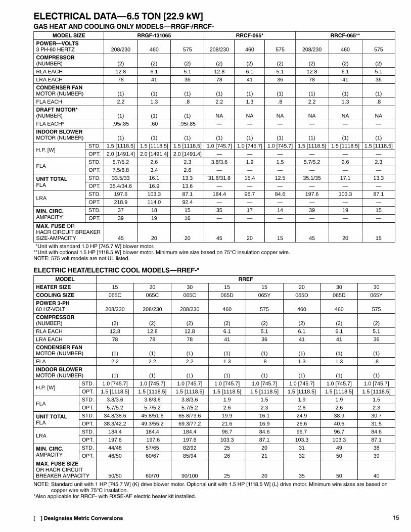
ELECTRICAL DATA—6.5 TON [22.9 kW]GAS HEAT AND COOLING ONLY MODELS—RRGF-/RRCF-
**Unit with standard 1.0 HP [745.7 W] blower motor.**Unit with optional 1.5 HP [1118.5 W] blower motor. Minimum wire size based on 75°C insulation copper wire.NOTE: 575 volt models are not UL listed.
NOTE: Standard unit with 1 HP [745.7 W] (K) drive blower motor. Optional unit with 1.5 HP [1118.5 W] (L) drive motor. Minimum wire sizes are based oncopper wire with 75°C insulation.
*Also applicable for RRCF- with RXSE-AF electric heater kit installed.
5.1RLA EACH 5.112.8 12.812.8 6.1 6.1 5.16.1
MODEL SIZE RRGF-131065 RRCF-065* RRCF-065**POWER—VOLTS3 PH-60 HERTZ 208/230 460 575 208/230 460 575 208/230 460 575
COMPRESSOR(NUMBER) (2) (2) (2) (2) (2) (2) (2) (2) (2)
LRA EACH 78 41 36 78 41 36 78 41 36
CONDENSER FANMOTOR (NUMBER) (1) (1) (1) (1) (1) (1) (1) (1) (1)
FLA EACH 2.2 1.3 .8 2.2 1.3 .8 2.2 1.3 .8
DRAFT MOTOR*(NUMBER) (1) (1) (1) NA NA NA NA NA NA
FLA EACH* .95/.85 .60 .95/.85 — — — — — —
INDOOR BLOWERMOTOR (NUMBER) (1) (1) (1) (1) (1) (1) (1) (1) (1)
H.P. [W]1.5 [1118.5] 1.5 [1118.5] 1.5 [1118.5] 1.0 [745.7] 1.0 [745.7] 1.0 [745.7] 1.5 [1118.5] 1.5 [1118.5] 1.5 [1118.5]
2.0 [1491.4] 2.0 [1491.4] 2.0 [1491.4] — — — — — —
MAX. FUSE ORHACR CIRCUIT BREAKERSIZE-AMPACITY 45 20 20 45 20 15 45 20 15
STD.
OPT.
STD.
OPT.FLA
5.7/5.2 2.6 2.3 3.8/3.6 1.9 1.5 5.7/5.2 2.6 2.3
7.5/6.8 3.4 2.6 — — — — — —
STD.
OPT.
STD.
OPT.LRA
197.6
UNIT TOTALFLA
33.5/33 16.1 13.3 31.6/31.8 15.4 12.5 35.1/35 17.1 13.3
103.3
35.4/34.6 16.9 13.6 — — — — — —
87.1 184.4 96.7 84.6 197.6 103.3 87.1
218.9 114.0 92.4 — — — — — —
STD.
OPT.MIN. CIRC.AMPACITY
37 18 15 35 17 14 39 19 15
39 19 16 — — — — — —
STD.
OPT.
STD.
OPT.H.P. [W]
1.0 [745.7]
460POWER 3-PH60 HZ-VOLT 208/230208/230 460460 575 575208/230
MODEL RREFHEATER SIZE 15 20 30 15 15 20 30 30
COOLING SIZE 065C 065C 065C 065D 065Y 065D 065D 065Y
COMPRESSOR(NUMBER) (2) (2) (2) (2) (2) (2) (2) (2)
RLA EACH 12.8 12.8 12.8 6.1 5.1 6.1 6.1 5.1
CONDENSER FANMOTOR (NUMBER) (1) (1) (1) (1) (1) (1) (1) (1)
FLA3.8/3.6 3.8/3.6 3.8/3.6 1.9 1.5 1.9 1.9 1.5
1.0 [745.7]
5.7/5.2 5.7/5.2 5.7/5.2 2.6 2.3 2.6 2.6 2.3
MAX. FUSE SIZEOR HACR CIRCUITBREAKER AMPACITY 50/50 60/70 90/100 25 20 35 50 40
1.0 [745.7] 1.0 [745.7] 1.0 [745.7] 1.0 [745.7] 1.0 [745.7] 1.0 [745.7]
1.5 [1118.5] 1.5 [1118.5] 1.5 [1118.5] 1.5 [1118.5] 1.5 [1118.5] 1.5 [1118.5] 1.5 [1118.5] 1.5 [1118.5]
STD.
OPT.
STD.
OPT.LRA
184.4
UNIT TOTALFLA
34.8/38.6 45.8/51.6 65.8/73.6 19.9 16.1 24.9 38.9 30.7
184.4
38.3/42.2 49.3/55.2 69.3/77.2 21.6 16.9 26.6 40.6 31.5
184.4 96.7 84.6 96.7 96.7 84.6
197.6 197.6 197.6 103.3 87.1 103.3 103.3 87.1
STD.
OPT.MIN. CIRC.AMPACITY
44/48 57/65 82/92 25 20 31 49 38
46/50 60/67 85/94 26 21 32 50 39
LRA EACH 78 78 78 41 36 41 41 36
FLA 2.2 2.2 2.2 1.3 .8 1.3 1.3 .8
INDOOR BLOWERMOTOR (NUMBER) (1) (1) (1) (1) (1) (1) (1) (1)
[ ] Designates Metric Conversions
ELECTRIC HEAT/ELECTRIC COOL MODELS—RREF-*

16
ELECTRICAL DATA—7.5 TON [26.4 kW]GAS HEAT AND COOLING ONLY MODELS—RRGF-/RRCF-
**Unit with standard 1.0 HP [745.7 W] blower motor.**Unit with optional 1.5 HP [1118.5 W] blower motor. Minimum wire size based on 75°C insulation copper wire.NOTE: 575 volt models are not UL listed.
NOTE: Standard unit with 1 HP [745.7 W] (K) drive blower motor. Optional unit with 1.5 HP [1118.5 W] (L) drive motor. Minimum wire sizes are based oncopper wire with 75°C insulation.
*Also applicable for RRCF- with RXSE-AF electric heater kit installed.
MODEL SIZE RRGF-131/201076
STD.
OPT.
RRCF-076*
STD.
OPT.
RRCF-076**
FLA5.7/5.2
POWER—VOLTS3 PH-60 HERTZ 208/230 460 575 208/230 460
5.4RLA EACH
575
5.4
208/230 460
15/14 15/14
575
15/14 7.5 7.5
COMPRESSOR(NUMBER) (2) (2) (2) (2)
5.47.5
(2) (2) (2) (2) (2)
LRA EACH 130 64 52 130 64 52 130 64 52
CONDENSER FANMOTOR (NUMBER) (1) (1) (1) (1) (1) (1) (1) (1) (1)
FLA EACH 2.2 1.3 .8 2.2 1.3 .8 2.2 1.3 .8
DRAFT MOTOR*(NUMBER) (1) (1) (1) NA NA NA NA NA NA
FLA EACH* .95/.85 .60 .95/.85 — — — — — —
INDOOR BLOWERMOTOR (NUMBER) (1) (1) (1) (1) (1) (1) (1) (1) (1)
H.P. [W]1.5 [1118.5] 1.5 [1118.5] 1.5 [1118.5] 1.0 [745.7] 1.0 [745.7] 1.0 [745.7] 1.5 [1118.5] 1.5 [1118.5] 1.5 [1118.5]
2.6
2.0 [1491.4] 2.0 [1491.4] 2.0 [1491.4] — — — — — —
MAX. FUSE ORHACR CIRCUIT BREAKERSIZE-AMPACITY 50 25 20 50 25 20 50 25 20
2.3 3.8/3.6 1.9 1.5 5.7/5.2 2.6 2.3
7.5/6.8 3.4 2.6 — — — — — —
STD.
OPT.
STD.
OPT.UNIT TOTALLRA
253.6
UNIT TOTALFLA
37.9/35.4 18.9 13.9 36.0/33.8 18.4 13.1 37.9/35.4 18.9 13.9
126.0
39.7/37 19.7 14.2 — — — — — —
103.1 240.4 1119.7 100.6 253.6 126.0 103.1
274.9 136.7 108.4 — — — — — —
STD.
OPT.MIN. CIRC.AMPACITY
42/40 21 16 40/38 20 15 40/42 21 16
44/42 22 17 — — — — — —
RLA EACH 15/14
STD.
OPT.
15/14
STD.
OPT.
15/14
H.P. [W]1.0 [745.7]
15/14 7.5 7.5 5.4 7.5
FLA
MODEL
2.2 2.2 2.2
RREF
2.2 1.3 1.3 .8 1.3
INDOOR BLOWERMOTOR (NUMBER) (1) (1) (1) (1) (1) (1) (1) (1)
COOLING SIZE 076C 076C 076C 076C 076D 076D 076Y 076D
POWER 3-PH60 HZ-VOLT 208/230 208/230 208/230 208/230 460 460 575 460
COMPRESSOR(NUMBER) (2) (2) (2) (2) (2) (2) (2) (2)
CONDENSER FANMOTOR (NUMBER) (1) (1) (1) (1) (1) (1) (1) (1)
FLA3.8/3.6 3.8/3.6 3.8/3.6 3.8/3.6 1.9 1.9 1.5 1.9
1.0 [745.7]
5.7/5.2 5.7/5.2 5.7/5.2 5.7/5.2 2.6 2.6 2.3 2.6
MAX. FUSE SIZEOR HACR CIRCUITBREAKER AMPACITY 50/50 60/70 90/100 110/125 25 35 25 50
1.0 [745.7] 1.0 [745.7] 1.0 [745.7] 1.0 [745.7] 1.0 [745.7] 1.0 [745.7]
1.5 [1118.5] 1.5 [1118.5] 1.5 [1118.5] 1.5 [1118.5] 1.5 [1118.5] 1.5 [1118.5] 1.5 [1118.5] 1.5 [1118.5]
STD.
OPT.
STD.
OPT.LRA
240
UNIT TOTALFLA
35.6/38.6 45.8/51.6 65.8/73.6 86.8/98.6 19.9 24.9 20.0 38.9
240
39.1/42.2 49.3/55.2 69.3/77.2 90.3/102.2 21.6 26.6 20.8 40.6
240 240 119 119 100.6 119
253 253 253 253 126 126 103.1 126
STD.
OPT.MIN. CIRC.AMPACITY
44/48 57/65 82/92 109/123 25 31 25 49
46/50 60/67 85/94 111/125 26 32 26 50
7.5 5.4
1.3 .8
(1) (1)
076D 076Y
460 575
(2) (2)
(1) (1)
1.9 1.5
2.6 2.3
60 50
1.0 [745.7] 1.0 [745.7]
1.5 [1118.5] 1.5 [1118.5]
47.9 38.5
49.6 39.3
119 100.6
126 103.1
60 48
61 49
LRA EACH 130 130 130 130 64 64 52 64 64 52
20HEATER SIZE 3015 2040 15 3020 40 40
ELECTRIC HEAT/ELECTRIC COOL MODELS—RREF-*
[ ] Designates Metric Conversions
17
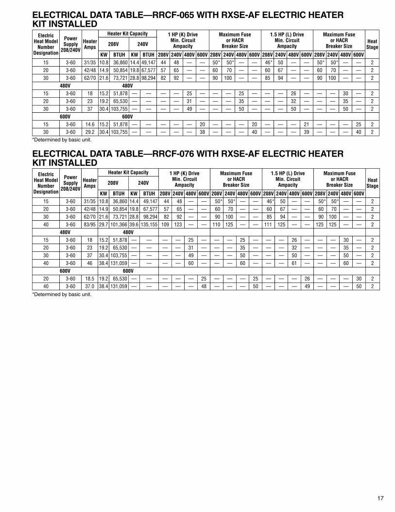
ELECTRICAL DATA TABLE—RRCF-065 WITH RXSE-AF ELECTRIC HEATERKIT INSTALLED
ELECTRICAL DATA TABLE—RRCF-076 WITH RXSE-AF ELECTRIC HEATERKIT INSTALLED
*Determined by basic unit.
*Determined by basic unit.
ElectricHeat Model
NumberDesignation
Heater Kit CapacityPowerSupply
208/240V208V
KW15 10.83-60 36,860
BTUH14.4KW
240V
31/35
HeaterAmps
49,147BTUH
44208V
1 HP (K) DriveMin. Circuit
Ampacity
48240V
—480V
—600V
50*208V
Maximum Fuseor HACR
Breaker Size
50*240V
—480V
—600V
46*208V
1.5 HP (L) DriveMin. Circuit
Ampacity
50240V
—480V
—600V
50*208V
Maximum Fuseor HACR
Breaker Size
50*240V
—480V
—600V
2
HeatStage
20 3-60 42/48 14.9 50,854 19.8 67,577 57 65 — — 60 70 — — 60 67 — — 60 70 — — 230 3-60 62/70 21.6 73,721 28.8 98,294 82 92 — — 90 100 — — 85 94 — — 90 100 — — 2
480V 480V15 3-60 18 15.2 51,878 — — — — 25 — — — 25 — — — 26 — — — 30 — 220 3-60 23 19.2 65,530 — — — — 31 — — — 35 — — — 32 — — — 35 — 230 3-60 37 30.4 103,755 — — — — 49 — — — 50 — — — 50 — — — 50 — 2
15 3-60 14.6 15.2 51,878 — — — — — 20 — — — 20 — — — 21 — — — 25 230 3-60 29.2 30.4 103,755 — — — — — 38 — — — 40 — — — 39 — — — 40 2
600V 600V
ElectricHeat Model
NumberDesignation
Heater Kit CapacityPowerSupply
208/240V
600V
208V
600V
KW15 10.83-60 49,14736,860
BTUH BTUH14.4KW
240V
44208V
1 HP (K) DriveMin. Circuit
Ampacity
48240V
—480V
—600V
50*208V
Maximum Fuseor HACR
Breaker Size
50*240V
—480V
—600V
46*208V
1.5 HP (L) DriveMin. Circuit
Ampacity
50240V
—480V
—600V
50*208V
Maximum Fuseor HACR
Breaker Size
50*240V
—480V
—600V
2
HeatStage
20 3-60 42/48 14.9 50,854 19.8 67,577 57 65 — — 60 70 — — 60 67 — — 60 70 — — 230 3-60 62/70 21.6 73,721 28.8 98,294 82 92 — — 90 100 — — 85 94 — — 90 100 — — 2
480V 480V15 3-60 18 15.2 51,878 — — — — 25 — — — 25 — — — 26 — — — 30
31/35
HeaterAmps
— 220 3-60 23 19.2 65,530 — — — — 31 — — — 35 — — — 32 — — — 35 — 230 3-60 37 30.4 103,755 — — — — 49 — — — 50 — — — 50 — — — 50 — 2
20 3-60 18.5 19.2 65,530 — — — — — 25 — — — 25 — — — 26 — — — 30 240 3-60 37.0 38.4 131,059 — — — — — 48 — — — 50 — — — 49 — — — 50 2
40 3-60 83/95 29.7 101,366 39.6 135,155 109 123 — — 110 125 — — 111 125 — — 125 125 — — 2
40 3-60 46 38.4 131,059 — — — — 60 — — — 60 — — — 61 — — — 60 — 2
18
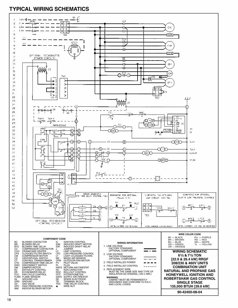
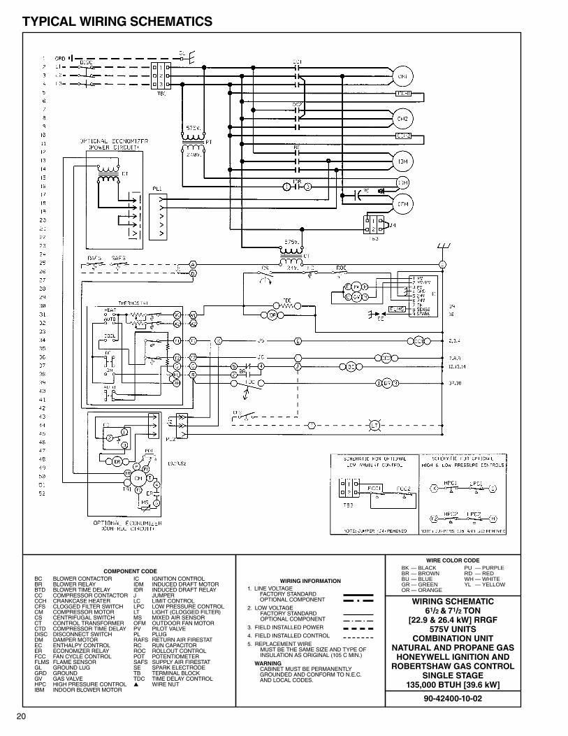
TYPICAL WIRING SCHEMATICS
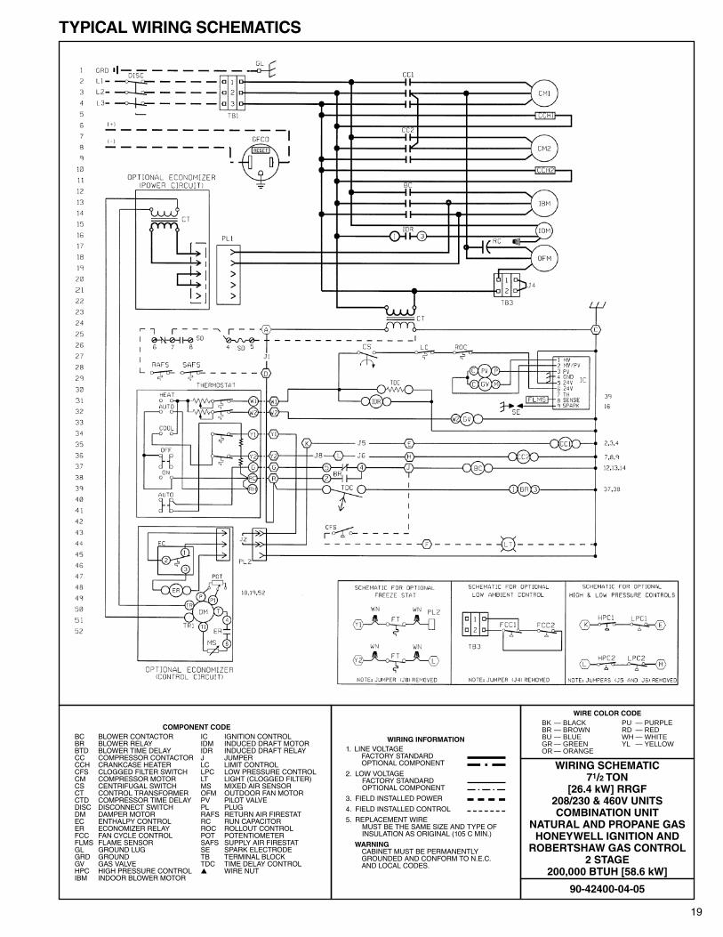
COMPONENT CODEBC BLOWER CONTACTOR IC IGNITION CONTROLBR BLOWER RELAY IDM INDUCED DRAFT MOTORBTD BLOWER TIME DELAY IDR INDUCED DRAFT RELAYCC COMPRESSOR CONTACTOR J JUMPERCCH CRANKCASE HEATER LC LIMIT CONTROLCFS CLOGGED FILTER SWITCH LPC LOW PRESSURE CONTROLCM COMPRESSOR MOTOR LT LIGHT (CLOGGED FILTER)CS CENTRIFUGAL SWITCH MS MIXED AIR SENSORCT CONTROL TRANSFORMER OFM OUTDOOR FAN MOTORCTD COMPRESSOR TIME DELAY PV PILOT VALVEDISC DISCONNECT SWITCH PL PLUGDM DAMPER MOTOR RAFS RETURN AIR FIRESTATEC ENTHALPY CONTROL RC RUN CAPACITORER ECONOMIZER RELAY ROC ROLLOUT CONTROLFCC FAN CYCLE CONTROL POT POTENTIOMETERFLMS FLAME SENSOR SAFS SUPPLY AIR FIRESTATGL GROUND LUG SE SPARK ELECTRODEGRD GROUND TB TERMINAL BLOCKGV GAS VALVE TDC TIME DELAY CONTROLHPC HIGH PRESSURE CONTROL ▲▲ WIRE NUTIBM INDOOR BLOWER MOTOR
WIRING INFORMATION1. LINE VOLTAGE
FACTORY STANDARDOPTIONAL COMPONENT
2. LOW VOLTAGEFACTORY STANDARDOPTIONAL COMPONENT
3. FIELD INSTALLED POWER
4. FIELD INSTALLED CONTROL
5. REPLACEMENT WIREMUST BE THE SAME SIZE AND TYPE OFINSULATION AS ORIGINAL (105 C MIN.)
WARNINGCABINET MUST BE PERMANENTLY GROUNDED AND CONFORM TO N.E.C.AND LOCAL CODES.
90-42400-08-04
WIRING SCHEMATIC61/2 & 71/2 TON
[22.9 & 26.4 kW] RRGF208/230 & 460V UNITSCOMBINATION UNIT
NATURAL AND PROPANE GASHONEYWELL IGNITION AND
ROBERTSHAW GAS CONTROLSINGLE STAGE
135,000 BTUH [39.6 kW]
WIRE COLOR CODEBK — BLACK PU — PURPLEBR — BROWN RD — REDBU — BLUE WH — WHITEGR — GREEN YL — YELLOWOR — ORANGE
19
TYPICAL WIRING SCHEMATICS
COMPONENT CODEBC BLOWER CONTACTOR IC IGNITION CONTROLBR BLOWER RELAY IDM INDUCED DRAFT MOTORBTD BLOWER TIME DELAY IDR INDUCED DRAFT RELAYCC COMPRESSOR CONTACTOR J JUMPERCCH CRANKCASE HEATER LC LIMIT CONTROLCFS CLOGGED FILTER SWITCH LPC LOW PRESSURE CONTROLCM COMPRESSOR MOTOR LT LIGHT (CLOGGED FILTER)CS CENTRIFUGAL SWITCH MS MIXED AIR SENSORCT CONTROL TRANSFORMER OFM OUTDOOR FAN MOTORCTD COMPRESSOR TIME DELAY PV PILOT VALVEDISC DISCONNECT SWITCH PL PLUGDM DAMPER MOTOR RAFS RETURN AIR FIRESTATEC ENTHALPY CONTROL RC RUN CAPACITORER ECONOMIZER RELAY ROC ROLLOUT CONTROLFCC FAN CYCLE CONTROL POT POTENTIOMETERFLMS FLAME SENSOR SAFS SUPPLY AIR FIRESTATGL GROUND LUG SE SPARK ELECTRODEGRD GROUND TB TERMINAL BLOCKGV GAS VALVE TDC TIME DELAY CONTROLHPC HIGH PRESSURE CONTROL ▲▲ WIRE NUTIBM INDOOR BLOWER MOTOR
WIRING INFORMATION1. LINE VOLTAGE
FACTORY STANDARDOPTIONAL COMPONENT
2. LOW VOLTAGEFACTORY STANDARDOPTIONAL COMPONENT
3. FIELD INSTALLED POWER
4. FIELD INSTALLED CONTROL
5. REPLACEMENT WIREMUST BE THE SAME SIZE AND TYPE OFINSULATION AS ORIGINAL (105 C MIN.)
WARNINGCABINET MUST BE PERMANENTLY GROUNDED AND CONFORM TO N.E.C.AND LOCAL CODES.
90-42400-04-05
WIRING SCHEMATIC71/2 TON
[26.4 kW] RRGF208/230 & 460V UNITSCOMBINATION UNIT
NATURAL AND PROPANE GASHONEYWELL IGNITION AND
ROBERTSHAW GAS CONTROL2 STAGE
200,000 BTUH [58.6 kW]
WIRE COLOR CODEBK — BLACK PU — PURPLEBR — BROWN RD — REDBU — BLUE WH — WHITEGR — GREEN YL — YELLOWOR — ORANGE
20
TYPICAL WIRING SCHEMATICS
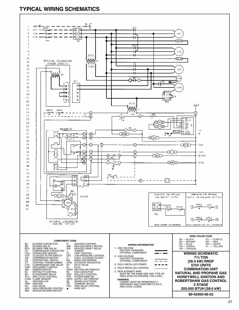
COMPONENT CODEBC BLOWER CONTACTOR IC IGNITION CONTROLBR BLOWER RELAY IDM INDUCED DRAFT MOTORBTD BLOWER TIME DELAY IDR INDUCED DRAFT RELAYCC COMPRESSOR CONTACTOR J JUMPERCCH CRANKCASE HEATER LC LIMIT CONTROLCFS CLOGGED FILTER SWITCH LPC LOW PRESSURE CONTROLCM COMPRESSOR MOTOR LT LIGHT (CLOGGED FILTER)CS CENTRIFUGAL SWITCH MS MIXED AIR SENSORCT CONTROL TRANSFORMER OFM OUTDOOR FAN MOTORCTD COMPRESSOR TIME DELAY PV PILOT VALVEDISC DISCONNECT SWITCH PL PLUGDM DAMPER MOTOR RAFS RETURN AIR FIRESTATEC ENTHALPY CONTROL RC RUN CAPACITORER ECONOMIZER RELAY ROC ROLLOUT CONTROLFCC FAN CYCLE CONTROL POT POTENTIOMETERFLMS FLAME SENSOR SAFS SUPPLY AIR FIRESTATGL GROUND LUG SE SPARK ELECTRODEGRD GROUND TB TERMINAL BLOCKGV GAS VALVE TDC TIME DELAY CONTROLHPC HIGH PRESSURE CONTROL ▲▲ WIRE NUTIBM INDOOR BLOWER MOTOR
WIRING INFORMATION1. LINE VOLTAGE
FACTORY STANDARDOPTIONAL COMPONENT
2. LOW VOLTAGEFACTORY STANDARDOPTIONAL COMPONENT
3. FIELD INSTALLED POWER
4. FIELD INSTALLED CONTROL
5. REPLACEMENT WIREMUST BE THE SAME SIZE AND TYPE OFINSULATION AS ORIGINAL (105 C MIN.)
WARNINGCABINET MUST BE PERMANENTLY GROUNDED AND CONFORM TO N.E.C.AND LOCAL CODES.
90-42400-10-02
WIRING SCHEMATIC61/2 & 71/2 TON
[22.9 & 26.4 kW] RRGF575V UNITS
COMBINATION UNITNATURAL AND PROPANE GAS
HONEYWELL IGNITION ANDROBERTSHAW GAS CONTROL
SINGLE STAGE135,000 BTUH [39.6 kW]
WIRE COLOR CODEBK — BLACK PU — PURPLEBR — BROWN RD — REDBU — BLUE WH — WHITEGR — GREEN YL — YELLOWOR — ORANGE
21
TYPICAL WIRING SCHEMATICS
COMPONENT CODEBC BLOWER CONTACTOR IC IGNITION CONTROLBR BLOWER RELAY IDM INDUCED DRAFT MOTORBTD BLOWER TIME DELAY IDR INDUCED DRAFT RELAYCC COMPRESSOR CONTACTOR J JUMPERCCH CRANKCASE HEATER LC LIMIT CONTROLCFS CLOGGED FILTER SWITCH LPC LOW PRESSURE CONTROLCM COMPRESSOR MOTOR LT LIGHT (CLOGGED FILTER)CS CENTRIFUGAL SWITCH MS MIXED AIR SENSORCT CONTROL TRANSFORMER OFM OUTDOOR FAN MOTORCTD COMPRESSOR TIME DELAY PV PILOT VALVEDISC DISCONNECT SWITCH PL PLUGDM DAMPER MOTOR RAFS RETURN AIR FIRESTATEC ENTHALPY CONTROL RC RUN CAPACITORER ECONOMIZER RELAY ROC ROLLOUT CONTROLFCC FAN CYCLE CONTROL POT POTENTIOMETERFLMS FLAME SENSOR SAFS SUPPLY AIR FIRESTATGL GROUND LUG SE SPARK ELECTRODEGRD GROUND TB TERMINAL BLOCKGV GAS VALVE TDC TIME DELAY CONTROLHPC HIGH PRESSURE CONTROL ▲▲ WIRE NUTIBM INDOOR BLOWER MOTOR
WIRING INFORMATION1. LINE VOLTAGE
FACTORY STANDARDOPTIONAL COMPONENT
2. LOW VOLTAGEFACTORY STANDARDOPTIONAL COMPONENT
3. FIELD INSTALLED POWER
4. FIELD INSTALLED CONTROL
5. REPLACEMENT WIREMUST BE THE SAME SIZE AND TYPE OFINSULATION AS ORIGINAL (105 C MIN.)
WARNINGCABINET MUST BE PERMANENTLY GROUNDED AND CONFORM TO N.E.C.AND LOCAL CODES.
90-42400-06-03
WIRING SCHEMATIC71/2 TON
[26.4 kW] RRGF575V UNITS
COMBINATION UNITNATURAL AND PROPANE GAS
HONEYWELL IGNITION ANDROBERTSHAW GAS CONTROL
2 STAGE200,000 BTUH [58.6 kW]
WIRE COLOR CODEBK — BLACK PU — PURPLEBR — BROWN RD — REDBU — BLUE WH — WHITEGR — GREEN YL — YELLOWOR — ORANGE
22
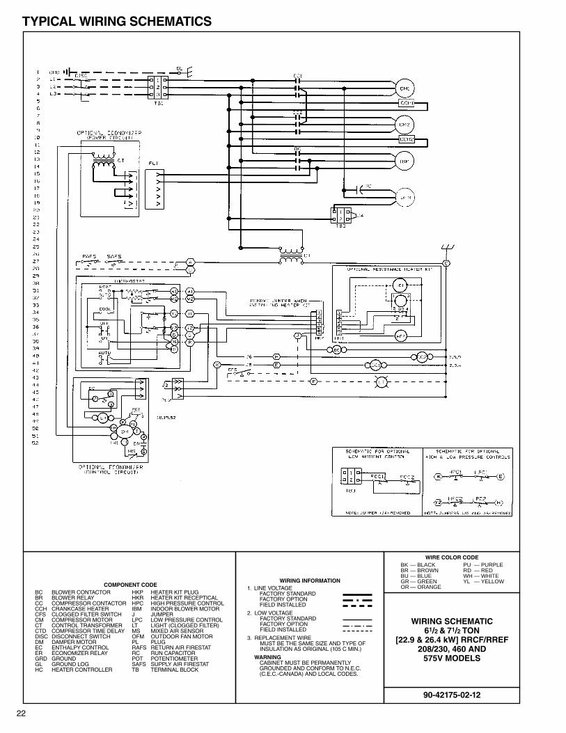
TYPICAL WIRING SCHEMATICS
COMPONENT CODEBC BLOWER CONTACTOR HKP HEATER KIT PLUGBR BLOWER RELAY HKR HEATER KIT RECEPTICALCC COMPRESSOR CONTACTOR HPC HIGH PRESSURE CONTROLCCH CRANKCASE HEATER IBM INDOOR BLOWER MOTORCFS CLOGGED FILTER SWITCH J JUMPERCM COMPRESSOR MOTOR LPC LOW PRESSURE CONTROLCT CONTROL TRANSFORMER LT LIGHT (CLOGGED FILTER)CTD COMPRESSOR TIME DELAY MS MIXED AIR SENSORDISC DISCONNECT SWITCH OFM OUTDOOR FAN MOTORDM DAMPER MOTOR PL PLUGEC ENTHALPY CONTROL RAFS RETURN AIR FIRESTATER ECONOMIZER RELAY RC RUN CAPACITORGRD GROUND POT POTENTIOMETERGL GROUND LOG SAFS SUPPLY AIR FIRESTATHC HEATER CONTROLLER TB TERMINAL BLOCK
WIRING INFORMATION1. LINE VOLTAGE
FACTORY STANDARDFACTORY OPTIONFIELD INSTALLED
2. LOW VOLTAGEFACTORY STANDARDFACTORY OPTIONFIELD INSTALLED
3. REPLACEMENT WIREMUST BE THE SAME SIZE AND TYPE OFINSULATION AS ORIGINAL (105 C MIN.)
WARNINGCABINET MUST BE PERMANENTLY GROUNDED AND CONFORM TO N.E.C.(C.E.C.-CANADA) AND LOCAL CODES.
90-42175-02-12
WIRING SCHEMATIC61/2 & 71/2 TON
[22.9 & 26.4 kW] RRCF/RREF208/230, 460 AND
575V MODELS
WIRE COLOR CODEBK — BLACK PU — PURPLEBR — BROWN RD — REDBU — BLUE WH — WHITEGR — GREEN YL — YELLOWOR — ORANGE
23
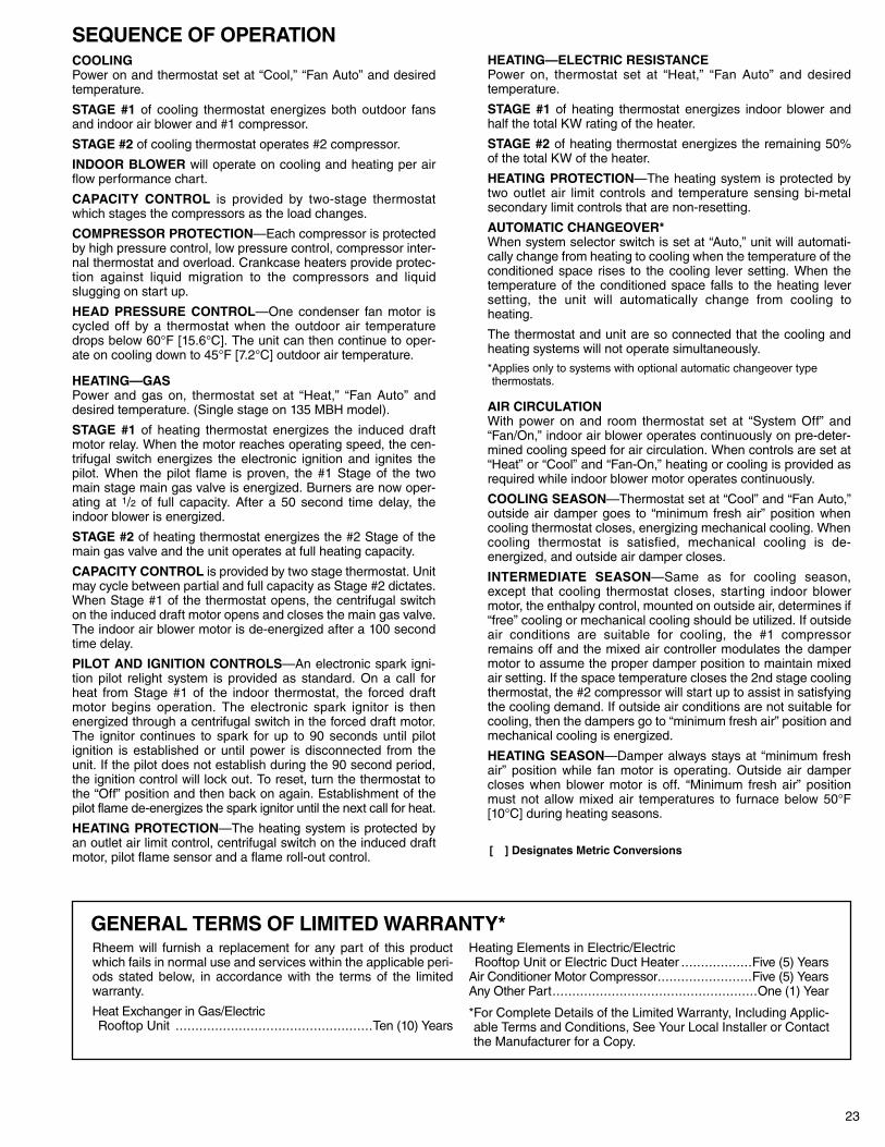
SEQUENCE OF OPERATIONCOOLINGPower on and thermostat set at “Cool,” “Fan Auto” and desiredtemperature.
STAGE #1 of cooling thermostat energizes both outdoor fansand indoor air blower and #1 compressor.
STAGE #2 of cooling thermostat operates #2 compressor.
INDOOR BLOWER will operate on cooling and heating per airflow performance chart.
CAPACITY CONTROL is provided by two-stage thermostatwhich stages the compressors as the load changes.
COMPRESSOR PROTECTION—Each compressor is protectedby high pressure control, low pressure control, compressor inter-nal thermostat and overload. Crankcase heaters provide protec-tion against liquid migration to the compressors and liquidslugging on start up.
HEAD PRESSURE CONTROL—One condenser fan motor iscycled off by a thermostat when the outdoor air temperaturedrops below 60°F [15.6°C]. The unit can then continue to oper-ate on cooling down to 45°F [7.2°C] outdoor air temperature.
HEATING—GASPower and gas on, thermostat set at “Heat,” “Fan Auto” anddesired temperature. (Single stage on 135 MBH model).
STAGE #1 of heating thermostat energizes the induced draftmotor relay. When the motor reaches operating speed, the cen-trifugal switch energizes the electronic ignition and ignites thepilot. When the pilot flame is proven, the #1 Stage of the twomain stage main gas valve is energized. Burners are now oper-ating at 1/2 of full capacity. After a 50 second time delay, theindoor blower is energized.
STAGE #2 of heating thermostat energizes the #2 Stage of themain gas valve and the unit operates at full heating capacity.
CAPACITY CONTROL is provided by two stage thermostat. Unitmay cycle between partial and full capacity as Stage #2 dictates.When Stage #1 of the thermostat opens, the centrifugal switchon the induced draft motor opens and closes the main gas valve.The indoor air blower motor is de-energized after a 100 secondtime delay.
PILOT AND IGNITION CONTROLS—An electronic spark igni-tion pilot relight system is provided as standard. On a call forheat from Stage #1 of the indoor thermostat, the forced draftmotor begins operation. The electronic spark ignitor is thenenergized through a centrifugal switch in the forced draft motor.The ignitor continues to spark for up to 90 seconds until pilotignition is established or until power is disconnected from theunit. If the pilot does not establish during the 90 second period,the ignition control will lock out. To reset, turn the thermostat tothe “Off” position and then back on again. Establishment of thepilot flame de-energizes the spark ignitor until the next call for heat.
HEATING PROTECTION—The heating system is protected byan outlet air limit control, centrifugal switch on the induced draftmotor, pilot flame sensor and a flame roll-out control.
HEATING—ELECTRIC RESISTANCEPower on, thermostat set at “Heat,” “Fan Auto” and desiredtemperature.
STAGE #1 of heating thermostat energizes indoor blower andhalf the total KW rating of the heater.
STAGE #2 of heating thermostat energizes the remaining 50%of the total KW of the heater.
HEATING PROTECTION—The heating system is protected bytwo outlet air limit controls and temperature sensing bi-metalsecondary limit controls that are non-resetting.
AUTOMATIC CHANGEOVER*When system selector switch is set at “Auto,” unit will automati-cally change from heating to cooling when the temperature of theconditioned space rises to the cooling lever setting. When thetemperature of the conditioned space falls to the heating leversetting, the unit will automatically change from cooling toheating.
The thermostat and unit are so connected that the cooling andheating systems will not operate simultaneously.
*Applies only to systems with optional automatic changeover typethermostats.
AIR CIRCULATIONWith power on and room thermostat set at “System Off” and“Fan/On,” indoor air blower operates continuously on pre-deter-mined cooling speed for air circulation. When controls are set at“Heat” or “Cool” and “Fan-On,” heating or cooling is provided asrequired while indoor blower motor operates continuously.
COOLING SEASON—Thermostat set at “Cool” and “Fan Auto,”outside air damper goes to “minimum fresh air” position whencooling thermostat closes, energizing mechanical cooling. Whencooling thermostat is satisfied, mechanical cooling is de-energized, and outside air damper closes.
INTERMEDIATE SEASON—Same as for cooling season,except that cooling thermostat closes, starting indoor blowermotor, the enthalpy control, mounted on outside air, determines if“free” cooling or mechanical cooling should be utilized. If outsideair conditions are suitable for cooling, the #1 compressorremains off and the mixed air controller modulates the dampermotor to assume the proper damper position to maintain mixedair setting. If the space temperature closes the 2nd stage coolingthermostat, the #2 compressor will start up to assist in satisfyingthe cooling demand. If outside air conditions are not suitable forcooling, then the dampers go to “minimum fresh air” position andmechanical cooling is energized.
HEATING SEASON—Damper always stays at “minimum freshair” position while fan motor is operating. Outside air dampercloses when blower motor is off. “Minimum fresh air” positionmust not allow mixed air temperatures to furnace below 50°F[10°C] during heating seasons.
GENERAL TERMS OF LIMITED WARRANTY*Rheem will furnish a replacement for any part of this productwhich fails in normal use and services within the applicable peri-ods stated below, in accordance with the terms of the limitedwarranty.
Heat Exchanger in Gas/ElectricRooftop Unit ..................................................Ten (10) Years
Heating Elements in Electric/ElectricRooftop Unit or Electric Duct Heater ..................Five (5) Years
Air Conditioner Motor Compressor........................Five (5) YearsAny Other Part....................................................One (1) Year
*For Complete Details of the Limited Warranty, Including Applic-able Terms and Conditions, See Your Local Installer or Contactthe Manufacturer for a Copy.
[ ] Designates Metric Conversions
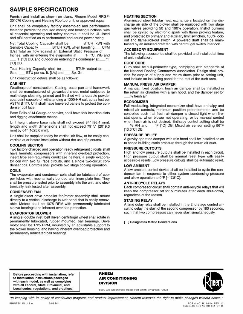
SAMPLE SPECIFICATIONSFurnish and install as shown on plans, Rheem Model RRGF-201076 Cooling and Heating Rooftop unit, or approved equal.
Unit shall be completely factory assembled and performancetested to provide the required cooling and heating functions, withall essential operating and safety controls. It shall be UL listedand ARI certified as to performance and sound power rating.
Net Total Cooling Capacity shall be ______ BTUH [kW] withSensible Capacity ______ BTUH [kW], when handling ___ CFM[L/s] Total air flow against an External Static Pressure of ___Inches, with air entering the evaporator at ___ °F [°C] WB and___ °F [°C] DB, and outdoor air entering the condenser at ___ °F[°C] DB.
Total Heating Capacity shall be ______ BTUH output on ___Gas, ___ BTU per cu. ft. [L/s] and ___ Sp. Gr.
Unit construction details shall be as follows:
CABINETWeatherproof construction. Casing, base pan and frameworkshall be manufactured of galvanized sheet metal subjected tomulti-stage cleaning, primed and finished with a durable powdercoat paint capable of withstanding a 1000-HR salt spray test perASTM B 117. Unit shall have louvered panels to protect the con-denser coil face.
Base Rails of 14 Gauge or heavier, shall have fork insertion slotsand rigging attachment means.
Unit height above base rails shall not exceed 34" [86.4 mm];length and width dimensions shall not exceed 791/2" [2019.3mm] by 64" [1625.6 mm].
Unit shall be supplied ready for vertical air flow, or be easily con-vertible at or before installation without the use of plenums.
COOLING SECTIONTwo factory charged and operation ready refrigerant circuits shallhave hermetic compressors with inherent overload protection,insert type self-regulating crankcase heaters, a single evapora-tor coil with two full face circuits, and a single two-circuit con-denser coil. Controls shall provide two stage cooling operation.
COILSThe evaporator and condenser coils shall be fabricated of cop-per tubes with mechanically bonded aluminum plate fins. Theyshall be pressure tested prior to assembly into the unit, and elec-tronically leak tested after assembly.
CONDENSER FANA single direct drive propeller fan/motor assembly shall mountdirectly to a vertical-discharge louver panel that is easily remov-able. Motors shall be 1075 RPM with permanently lubricatedsleeve bearings and inherent overload protection.
EVAPORATOR BLOWERA single, double inlet, belt driven centrifugal wheel shall rotate inpermanently lubricated, rubber mounted, ball bearings. Drivemotor shall be 1725 RPM, mounted by an adjustable support tothe blower housing, and having inherent overload protection andpermanently lubricated ball bearings.
HEATING SECTIONAluminized steel tubular heat exchangers located on the dis-charge air side of the blower shall be equipped with two stagegas valves providing 50 and 100% operation. Inshot burnersshall be ignited by electronic spark with flame proving feature,and protected by primary and auxiliary limit switches, 100% lock-out and flame roll-out switch. A powered draft shall be main-tained by an induced draft fan with centrifugal switch interlock.
ACCESSORY EQUIPMENTThe following accessories shall be provided and installed at timeof unit installation.
ROOF CURBCurb shall be full-perimeter type, complying with standards ofthe National Roofing Contractors Association. Design shall pro-vide for drop-in of supply and return ducts prior to setting unit,and include an insulating panel for the rest of the curb area.
MANUAL FRESH AIR DAMPERA manual, fixed position, fresh air damper shall be installed inthe return air chamber with a rain hood, and the damper set for___% fresh air.
ECONOMIZERFull modulating, integrated economizer shall have enthalpy andmixed air controls, minimum position potentiometer, and becontrolled such that fresh air damper is closed tight when fire-stat opens, when blower not operating, or by manual controlwhen fresh air is not desired. Enthalpy control setting shall be___% RH and ___°F [°C] DB. Mixed air sensor setting 56°F[13.3°C] DB.
PRESSURE RELIEFA gravity operated damper with rain hood shall be installed so asto sense building static pressure through the return air duct.
PRESSURE CUTOUTSHigh and low pressure cutouts shall be installed in each circuit.High pressure cutout shall be manual reset type with easilyaccessible resets. Low pressure cutouts shall be automatic reset.
LOW AMBIENTA low ambient control device shall be installed to cycle the con-denser fan in response to either system condensing pressureand allow operation to 0°F [–17.8°C].
ANTI-RECYCLE RELAYSEach compressor circuit shall contain anti-recycle relays that willkeep the compressor off for 5 minutes after each shut-down,regardless of the reason.
STAGING RELAYA time delay relay shall be installed in the 2nd stage control cir-cuit to delay the start of the second compressor by 180 seconds,such that two compressors can never start simultaneously.
[ ] Designates Metric Conversions
Before proceeding with installation, referto installation instructions packagedwith each model, as well as complyingwith all Federal, State, Provincial, andLocal codes, regulations, and practices.
RHEEMAIR CONDITIONINGDIVISION
5600 Old Greenwood Road, Fort Smith, Arkansas 72903
“In keeping with its policy of continuous progress and product improvement, Rheem reserves the right to make changes without notice.”
PRINTED IN U.S.A. 5-98 DC FORM NO. R11-814 REV. 11Supersedes Form No. R11-814 Rev. 10


![Commercial Heating and Cooling RRCF- Cooling Only RREF- …pts.myrheem.com/docstore/webdocs/servicedocs/histlib/... · 1997. 12. 15. · 12.5 & 15 NOMINAL TON UNITS [44 & 52.8 kW]](https://img.pdfslide.us/doc/110x75/607dc9d92952ec2ff609b2bb/commercial-heating-and-cooling-rrcf-cooling-only-rref-pts-1997-12-15-125.jpg)