Embed Size (px)
Citation preview
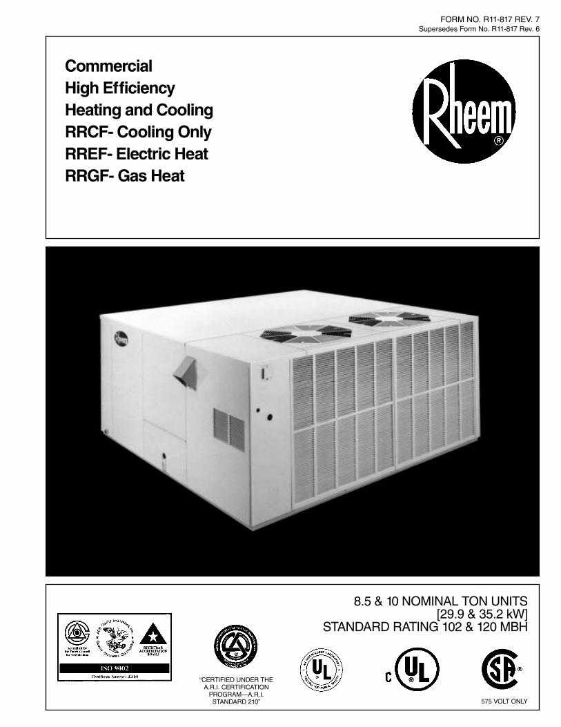
8.5 & 10 NOMINAL TON UNITS[29.9 & 35.2 kW]
STANDARD RATING 102 & 120 MBH
CommercialHigh EfficiencyHeating and CoolingRRCF- Cooling OnlyRREF- Electric HeatRRGF- Gas Heat
FORM NO. R11-817 REV. 7Supersedes Form No. R11-817 Rev. 6
“CERTIFIED UNDER THEA.R.I. CERTIFICATION
PROGRAM—A.R.I.STANDARD 210” 575 VOLT ONLY
2
R RG F- 200 085 C K RType of GasR–Natural A–Natural(U.S.) (Canadian)
Drive PackageK–StandardL–Optional
Electrical CharacteristicsC–3/60/208/230D–3/60/460Y–3/60/575 (Canadian)
Nominal Tons Cooling Capacity085–8.5 Tons [29.9 kW]100–10.0 Tons [35.2 kW]
Electric Heat–Total kW015–15 kW 040-40 kW020–20 kW 060-60 kW (60 kW for030–30 kW 10 Ton [35.2 kW] Only
Gas Heat200–200,000 BTUH [58.6 kW]250–250,000 BTUH [73.3 kW]–10 Ton
[35.2 kW] Only
SeriesF–New Design Series
Rooftop–Type HeatingRG-Gas–8.5 & 10 Ton [29.9 & 35.2 kW]RE-Electric–8.5 & 10 Ton [29.9 & 35.2 kW]RC-Cool only–8.5 & 10 Ton [29.9 & 35.2 kW]
Model DesignationR = Rheem
[ ] Designates Metric Conversions
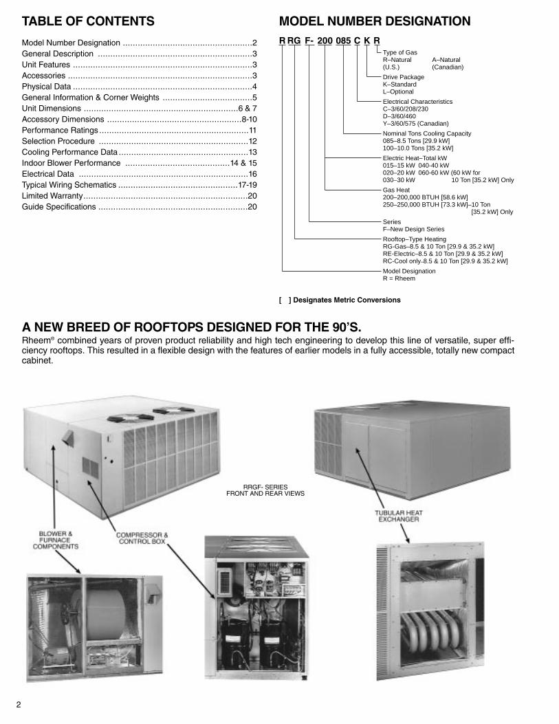
A NEW BREED OF ROOFTOPS DESIGNED FOR THE 90’S.Rheem® combined years of proven product reliability and high tech engineering to develop this line of versatile, super effi-ciency rooftops. This resulted in a flexible design with the features of earlier models in a fully accessible, totally new compactcabinet.
TABLE OF CONTENTS
Model Number Designation ....................................................2General Description ..............................................................3Unit Features ........................................................................3Accessories ..........................................................................3Physical Data ........................................................................4General Information & Corner Weights ....................................5Unit Dimensions ..............................................................6 & 7Accessory Dimensions ......................................................8-10Performance Ratings ............................................................11Selection Procedure ............................................................12Cooling Performance Data ....................................................13Indoor Blower Performance ..........................................14 & 15Electrical Data ....................................................................16Typical Wiring Schematics ................................................17-19Limited Warranty..................................................................20Guide Specifications ............................................................20
MODEL NUMBER DESIGNATION
RRGF- SERIESFRONT AND REAR VIEWS

3[ ] Designates Metric Conversions
GENERAL DESCRIPTIONThe Rheem RRCF-, RREF- and RRGF- series rooftops are designed foroutdoor installation. Their cabinets and condenser base pans are powdercoat painted. Cabinets are fully insulated and gasketed to resist all types ofweather conditions. All models are shipped ready for downflow duct appli-cation requiring no additional labor to remove panels. For sideflow ducting,duct cap panels are easily repositioned in the field. Economizer and freshair damper accessories are designed for use in either duct configuration.The units are evacuated to remove moisture from the refrigeration system,precisely charged with the refrigerant and run tested at the factory prior toshipment.
RRGF-The combination rooftops provide comfort conditioning in all seasons. Twoseparate cooling circuits supply cool air to meet the demands of hot sum-mer days. One cooling circuit operates independently to satisfy the needson warm spring and fall days. The gas furnace furnishes two stages ofheat during cold winter weather. For those cool nights when full capacity isnot needed, the first stage heat operates to produce the right amount ofwarm air.
RREF-The electric heat models offer the same cooling characteristics and fea-tures as the gas heat models but factory installed electric heating ele-ments warm the building supply air. The electric heaters are designed fortwo stages of heat and are wired to balance the electrical load across thethree phase power. Unit mounted terminal blocks and internal branch fus-ing allow single point external power wiring which eliminates the need forseparate power circuits to the electric heater and the cooling sections, thusreducing installation costs.
RRCF-The cooling only models deliver high efficiency cooling in two capacitysteps. A wide range of electric heat accessories can be field installed inthe unit to satisfy heating requirements. All operating parts of the unit areaccessible through exterior panels. The control components are mountedin one conveniently located control box. The control box and compressoraccess panel can be removed for servicing without interfering with con-denser air flow.
FEATURESENCLOSURE• Galvanized Steel• Powder coat painted cabinet and condenser base pan, capable of with-
standing a 1000-HR salt spray test per ASTM B 117.• Indoor section panels insulated with high density glass fiber.• Louvered inlet panels protecting condenser coil are standard.• Weather tight construction.
COMPRESSORS• Two sealed hermetics, in separate refrigerant circuits, have internal over-
load protection.• Internal spring and external rubber mounts provide compressor isolation.• Insert type crankcase heaters.• High and low pressure controls.
CONDENSER COIL• Copper tubes with mechanically bonded aluminum plate fins.• Two-row, circuited for two refrigerant systems.
CONDENSER FAN• Vertical discharge, direct drive.• Permanently lubricated “PSC” motor has inherent thermal overload.• Discharge grille easily removable for access to fan, motor and coil.
EVAPORATOR COIL• Copper tubes with mechanically bonded aluminum plate fins.• Four row, two circuit, interlaced design provides full-face cooling at
part load.• Refrigerant flow control by filter-protected capillary tubes.• Galvanized steel drain pan with threaded connector on side.
FILTERS• Filter frame holds 2" [50.8 mm] filters—throwaway type provided.• Access panel and unique clip arrangement allows easy replacement.
INDOOR BLOWER• Adjustable belt drive, forwardly curved centrifugal fan.• Alternate motors and drives available to meet job requirements.• Motor and fan shaft have permanently lubricated ball bearings.
ELECTRICAL• Control box easily accessible for power and control connections.• Factory wiring provides terminal strips and remote plugs with designated
jumpers for easy, fool-proof, accessory installation.• Single point power wiring.
GAS HEAT• Natural gas.• Aluminized steel tubular heat exchangers.• In-shot burners with induced draft combustion air have spark ignition
(100% Lockout) system.• Two stage heating.
ELECTRIC HEAT• Five sizes available ranging from 15 kW to 60 kW. (60 kW for 10 Ton
only)• Factory installed in RREF- models complete with wiring and appropriate
fuses.• Field installed electric heat available for use in RRCF- model.
APPLICATION• Cooling operation to 45°F [7.2°C]. Field add low ambient controls.• Shipped for vertical airflow—relocate two panels for horizontal.
QUALITY ASSURANCE• All production units are run tested at the factory.• Certified to applicable ARI Standards.• Listed to applicable U.L. and CSA Standards, and tested in accordance
with ANSI Standard Z21.47.
ACCESSORIESRXRK-E54 ROOF CURB—Full perimeter curb with insulation panel underoperating components provides for duct attachment prior to setting unit.Complies with NRCA Standards.
RXRF-CA54 MANUAL FRESH AIR DAMPER—Fixed position, fieldadjustable (0-25%) fresh air damper.
RXRQ-FM54Z ECONOMIZER—Fully modulating, integrated, enthalpycontrolled, with major parts pre-assembled and wired for plug-in installa-tion. Suitable for horizontal or vertical airflow application. Factory installedoption.
RXRP-E54 RELIEF DAMPER—Gravity operated damper and hoodassembly for use with economizer to relieve positive building pressure.
RXRT-C54 LOW AMBIENT—Two condensing pressure actuatedswitches, cycle condenser fan in response to pressure of operating cycle.Wire to terminal strip; connect capillaries to Schrader valves.
RXRW-C55 COMBINATION TIME DELAY BETWEEN COMPRESSORSAND ANTI-SHORT CYCLE TIMER—Instructions and components to pro-vide 5 minute delay and staging relay.
RXSE-BF ELECTRIC HEAT—Complete assembly includes elements,controls and wiring. Mounts in prepared area of RRCF- model. Designedfor single point power wiring.
RXRM-EB54 CONCENTRIC TRANSITION—Drops in roof curb prior toplacing unit. Directs supply air around the perimeter of center return duct.
RXRN-EE54 CONCENTRIC GRILLE—Used in conjunction with the con-centric transition. Grille mounts to the concentric ducts at ceiling level.
RXRJ-GP05W GAS CONVERSION KITS—Converts Natural gas units tooperate on Propane gas.
RXRJ-GP06W GAS CONVERSION KITS—Converts Natural gas units tooperate on Propane gas. (High altitude Canadian models only).
WALL THERMOSTAT—24 volt, 2 stage cool, 2 stage heat (Part #41-21444-01) with subbase, automatic (Part #41-21445-01) or manual (Part#41-21443-02) changeover; fan on or auto.
REMOTE INDICATOR PANEL—Panel has indicator lights to show fancooling and heating operations, (Part #41-21946-01).
REMOTE STATUS PANEL—Kit includes remote panel with indicatorlights, potentiometer and system switches, also has room thermostat forremote sensing and adjustment, (Part #41-21946-12).
4
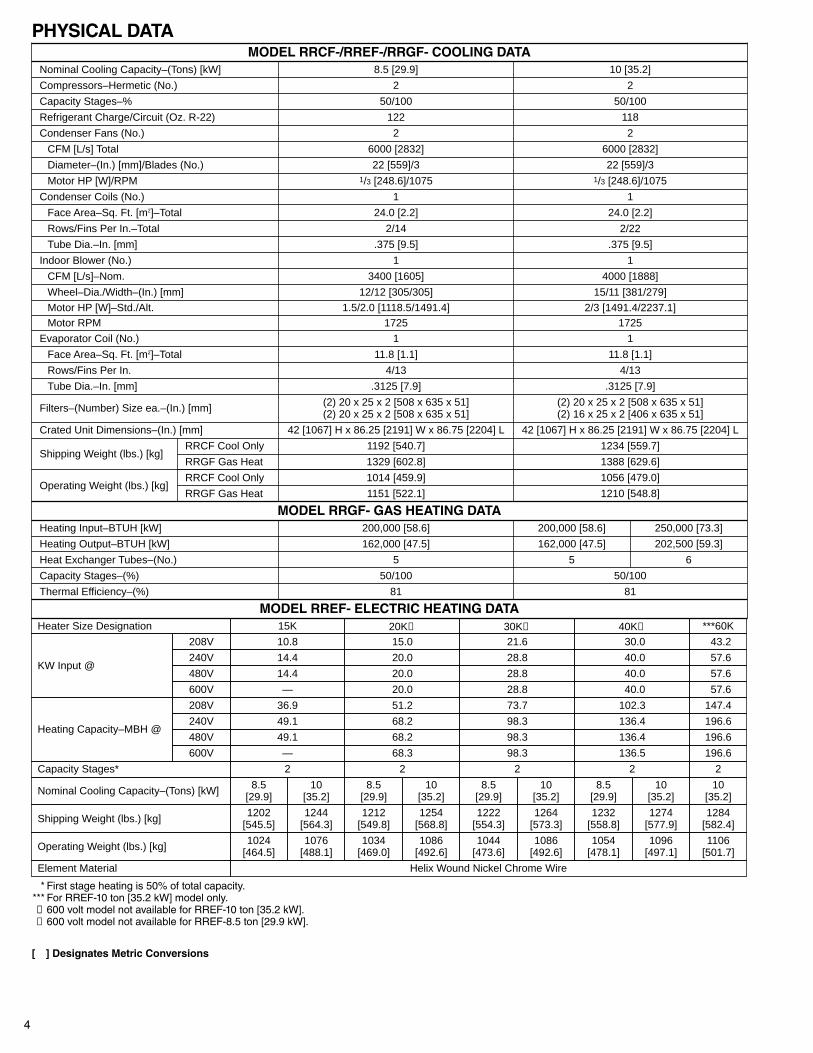
Compressors–Hermetic (No.)
Condenser Coils (No.)
2
Capacity Stages–%
1
50/100
Refrigerant Charge/Circuit (Oz. R-22)
1
122
Condenser Fans (No.) 2
CFM [L/s] Total 6000 [2832]
MODEL RRCF-/RREF-/RRGF- COOLING DATA
6
250,000 [73.3]
Diameter–(In.) [mm]/Blades (No.)
Nominal Cooling Capacity–(Tons) [kW] 8.5 [29.9]
22 [559]/3
Motor HP [W]/RPM 1/3 [248.6]/1075
Face Area–Sq. Ft. [m2]–Total 24.0 [2.2]
Rows/Fins Per In.–Total 2/14
Tube Dia.–In. [mm] .375 [9.5]
Indoor Blower (No.) 1
CFM [L/s]–Nom. 3400 [1605]
Wheel–Dia./Width–(In.) [mm] 12/12 [305/305]
Motor HP [W]–Std./Alt. 1.5/2.0 [1118.5/1491.4]Motor RPM 1725
Evaporator Coil (No.) 1
Face Area–Sq. Ft. [m2]–Total 11.8 [1.1]
Rows/Fins Per In. 4/13
Tube Dia.–In. [mm] .3125 [7.9]
Filters–(Number) Size ea.–(In.) [mm] (2) 20 x 25 x 2 [508 x 635 x 51](2) 20 x 25 x 2 [508 x 635 x 51]
Crated Unit Dimensions–(In.) [mm] 42 [1067] H x 86.25 [2191] W x 86.75 [2204] L
Shipping Weight (lbs.) [kg]RRCF Cool Only 1192 [540.7]
RRGF Gas Heat 1329 [602.8]
Operating Weight (lbs.) [kg]RRCF Cool Only 1014 [459.9]
RRGF Gas Heat 1151 [522.1]
MODEL RRGF- GAS HEATING DATAHeating Input–BTUH [kW] 200,000 [58.6]
Heat Exchanger Tubes–(No.) 5
Capacity Stages–(%) 50/100
Thermal Efficiency–(%) 81
MODEL RREF- ELECTRIC HEATING DATA81
50/100
5
200,000 [58.6]
1210 [548.8]
1056 [479.0]
1388 [629.6]
1234 [559.7]
(2) 20 x 25 x 2 [508 x 635 x 51](2) 16 x 25 x 2 [406 x 635 x 51]
.3125 [7.9]
4/13
11.8 [1.1]
1
17252/3 [1491.4/2237.1]
15/11 [381/279]
4000 [1888]
1
.375 [9.5]
2/22
24.0 [2.2]
1/3 [248.6]/1075
22 [559]/3
6000 [2832]
2
118
50/100
2
10 [35.2]
42 [1067] H x 86.25 [2191] W x 86.75 [2204] L
202,500 [59.3]Heating Output–BTUH [kW] 162,000 [47.5] 162,000 [47.5]
Heater Size Designation 15K 20K➀ 30K➁ 40K➀
KW Input @
208V 10.8 15.0 21.6 30.0
240V 14.4 20.0 28.8 40.0
480V 14.4 20.0 28.8 40.0
600V — 20.0 28.8 40.0
Heating Capacity–MBH @
208V 36.9 51.2 73.7 102.3
240V 49.1 68.2 98.3 136.4
480V 49.1 68.2 98.3 136.4
600V — 68.3 98.3 136.5
Capacity Stages* 2 2 2 2
Nominal Cooling Capacity–(Tons) [kW] 8.5[29.9]
Shipping Weight (lbs.) [kg] 1202[545.5]
Operating Weight (lbs.) [kg] 1024[464.5]
8.5[29.9]
8.5[29.9]
8.5[29.9]
1232[558.8]
1222[554.3]
1212[549.8]
1054[478.1]
1044[473.6]
1034[469.0]
10[35.2]
***60K
43.2
57.6
57.6
1284[582.4]
57.6
147.4
196.6
196.6
1106[501.7]
196.6
2
Element Material Helix Wound Nickel Chrome Wire
10[35.2]
10[35.2]
10[35.2]
10[35.2]
1244[564.3]
1254[568.8]
1264[573.3]
1274[577.9]
1076[488.1]
1086[492.6]
1086[492.6]
1096[497.1]
PHYSICAL DATA
*** First stage heating is 50% of total capacity.*** For RREF-10 ton [35.2 kW] model only.➀ 600 volt model not available for RREF-10 ton [35.2 kW].➁ 600 volt model not available for RREF-8.5 ton [29.9 kW].
[ ] Designates Metric Conversions
5
GENERAL INFORMATIONLOCATING UNITConsult local building codes or ordinances for special installationrequirements. When selecting a site to locate the rooftop unit, con-sider the following:
ROOF MOUNTIf unit is to be roof mounted, check building codes for weight distri-bution requirements. Refer to accessory roofcurb mountinginstructions if unit is to be curb mounted. Check unit nameplate for supply voltage required. Determine if adequate electrical poweris available. Furnace may be installed on Class A, B or C roofingmaterial.
SLAB MOUNTProvide a level concrete slab that extends beyond unit cabinet atleast 6 inches [152 mm], with 4 inches [102 mm] above grade. Usea 24-inch [610 mm] gravel apron in front of outdoor air openings toprevent grass and foliage from obstructing air flow.
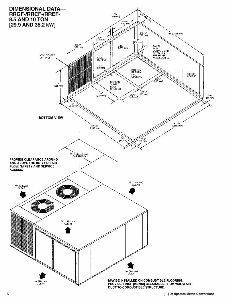
POSITIONINGUnit air inlets and outlets may be located in any compass directionas they are not affected by wind. Provide clearance around andabove the unit for air flow, safety, and service access. See page 6for minimum clearances.
FOR OUTDOOR INSTALLATION ONLYUnit is design certified for outdoor installation only. Do not installunit in any indoor location. Do not locate unit air inlets nearexhaust vents or other sources of contaminated air.Furnace venting as supplied with the unit must be used withoutalteration or addition. Consult your local utility BEFORE installing.Although unit is weatherproof, guard against water from higherlevel runoff and overhangs.
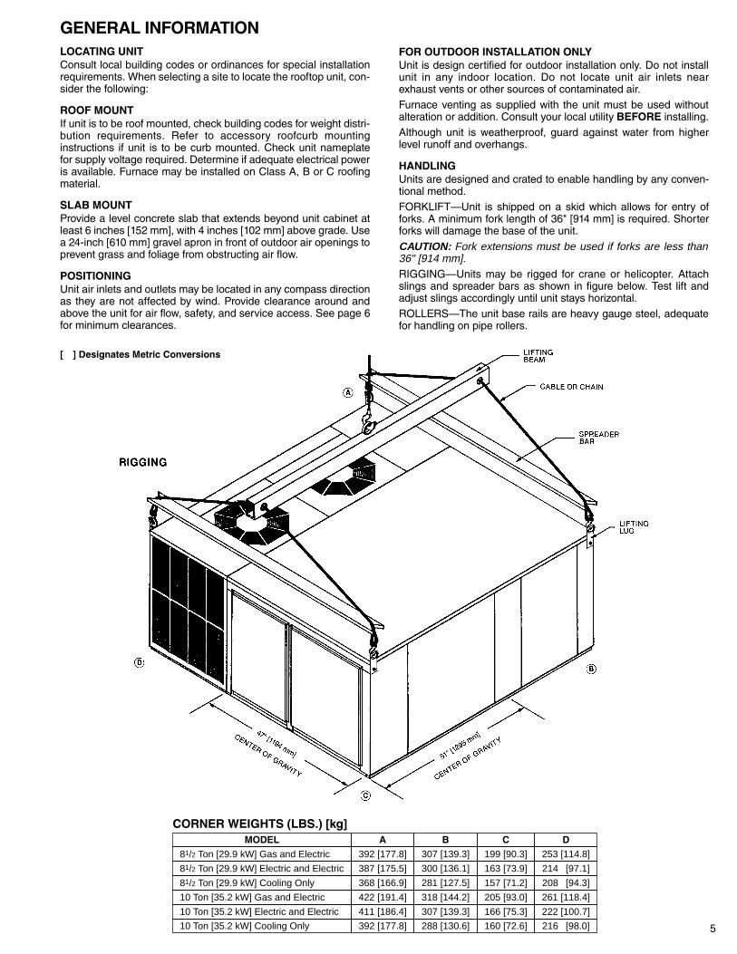
HANDLINGUnits are designed and crated to enable handling by any conven-tional method.FORKLIFT—Unit is shipped on a skid which allows for entry offorks. A minimum fork length of 36" [914 mm] is required. Shorterforks will damage the base of the unit.
CAUTION: Fork extensions must be used if forks are less than36" [914 mm].RIGGING—Units may be rigged for crane or helicopter. Attachslings and spreader bars as shown in figure below. Test lift andadjust slings accordingly until unit stays horizontal.ROLLERS—The unit base rails are heavy gauge steel, adequatefor handling on pipe rollers.
MODEL A B C D
81/2 Ton [29.9 kW] Gas and Electric 392 [177.8] 307 [139.3] 199 [90.3] 253 [114.8]
81/2 Ton [29.9 kW] Electric and Electric 387 [175.5] 300 [136.1] 163 [73.9] 214 [97.1]
81/2 Ton [29.9 kW] Cooling Only 368 [166.9] 281 [127.5] 157 [71.2] 208 [94.3]
10 Ton [35.2 kW] Gas and Electric 422 [191.4] 318 [144.2] 205 [93.0] 261 [118.4]
10 Ton [35.2 kW] Electric and Electric 411 [186.4] 307 [139.3] 166 [75.3] 222 [100.7]
10 Ton [35.2 kW] Cooling Only 392 [177.8] 288 [130.6] 160 [72.6] 216 [98.0]
CORNER WEIGHTS (LBS.) [kg]
[ ] Designates Metric Conversions
6
DIMENSIONAL DATA—RRGF-/RRCF-/RREF- 8.5 AND 10 TON [29.9 AND 35.2 kW]
[ ] Designates Metric Conversions
7
DIMENSIONAL DATA—
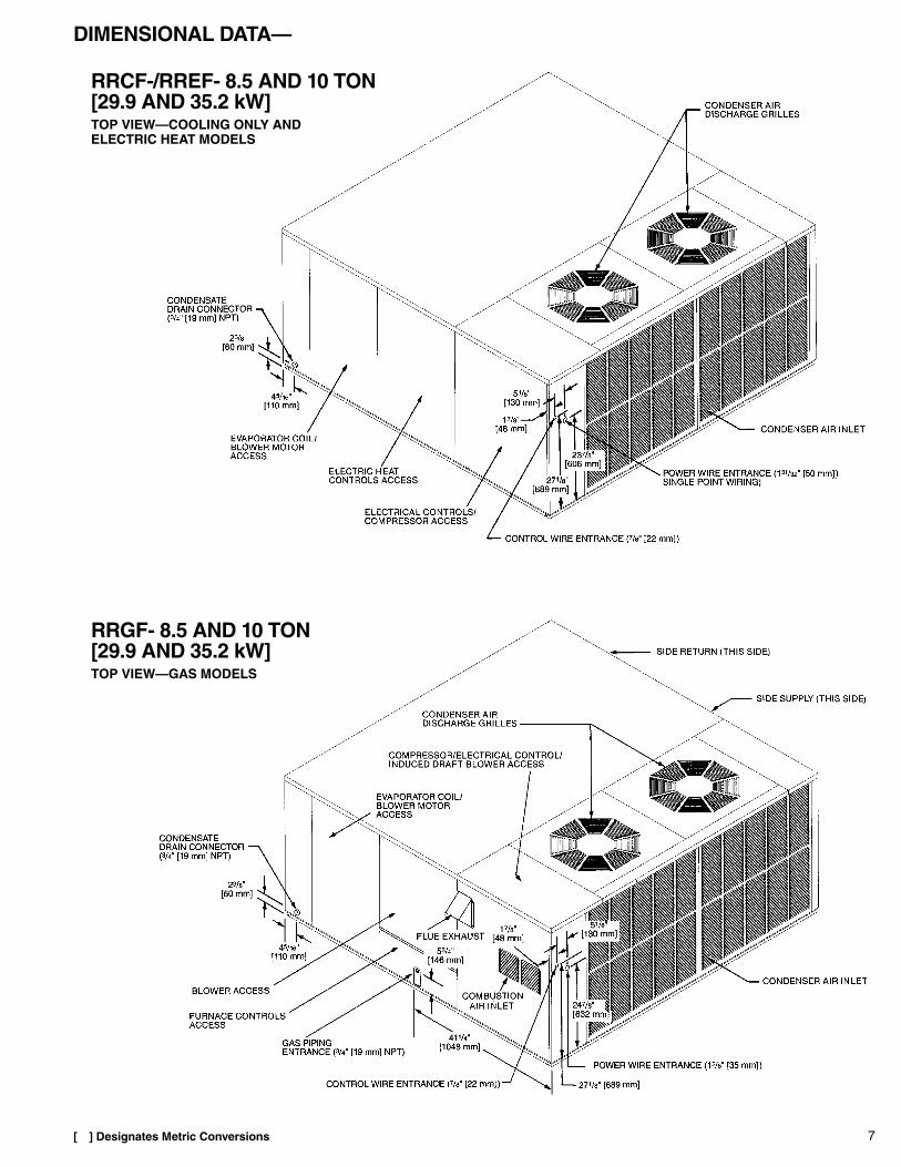
RRCF-/RREF- 8.5 AND 10 TON [29.9 AND 35.2 kW]TOP VIEW—COOLING ONLY ANDELECTRIC HEAT MODELS
RRGF- 8.5 AND 10 TON [29.9 AND 35.2 kW]TOP VIEW—GAS MODELS
[ ] Designates Metric Conversions
8
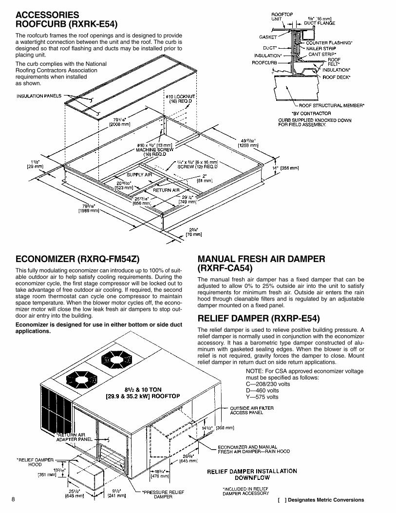
ACCESSORIESROOFCURB (RXRK-E54)The roofcurb frames the roof openings and is designed to providea watertight connection between the unit and the roof. The curb isdesigned so that roof flashing and ducts may be installed prior toplacing unit.
The curb complies with the NationalRoofing Contractors Associationrequirements when installedas shown.
ECONOMIZER (RXRQ-FM54Z)This fully modulating economizer can introduce up to 100% of suit-able outdoor air to help satisfy cooling requirements. During theeconomizer cycle, the first stage compressor will be locked out totake advantage of free outdoor air cooling. If required, the secondstage room thermostat can cycle one compressor to maintainspace temperature. When the blower motor cycles off, the econo-mizer motor will close the low leak fresh air dampers to stop out-door air entry into the building.
Economizer is designed for use in either bottom or side ductapplications.
MANUAL FRESH AIR DAMPER(RXRF-CA54)The manual fresh air damper has a fixed damper that can beadjusted to allow 0% to 25% outside air into the unit to satisfyrequirements for minimum fresh air. Outside air enters the rainhood through cleanable filters and is regulated by an adjustabledamper mounted on a fixed panel.
RELIEF DAMPER (RXRP-E54)The relief damper is used to relieve positive building pressure. Arelief damper is normally used in conjunction with the economizeraccessory. It has a barometric type damper constructed of alu-minum with gasketed sealing edges. When the blower is off orrelief is not required, gravity forces the damper to close. Mountrelief damper in return duct on side return applications.
NOTE: For CSA approved economizer voltagemust be specified as follows:C—208/230 voltsD—460 voltsY—575 volts
[ ] Designates Metric Conversions
9
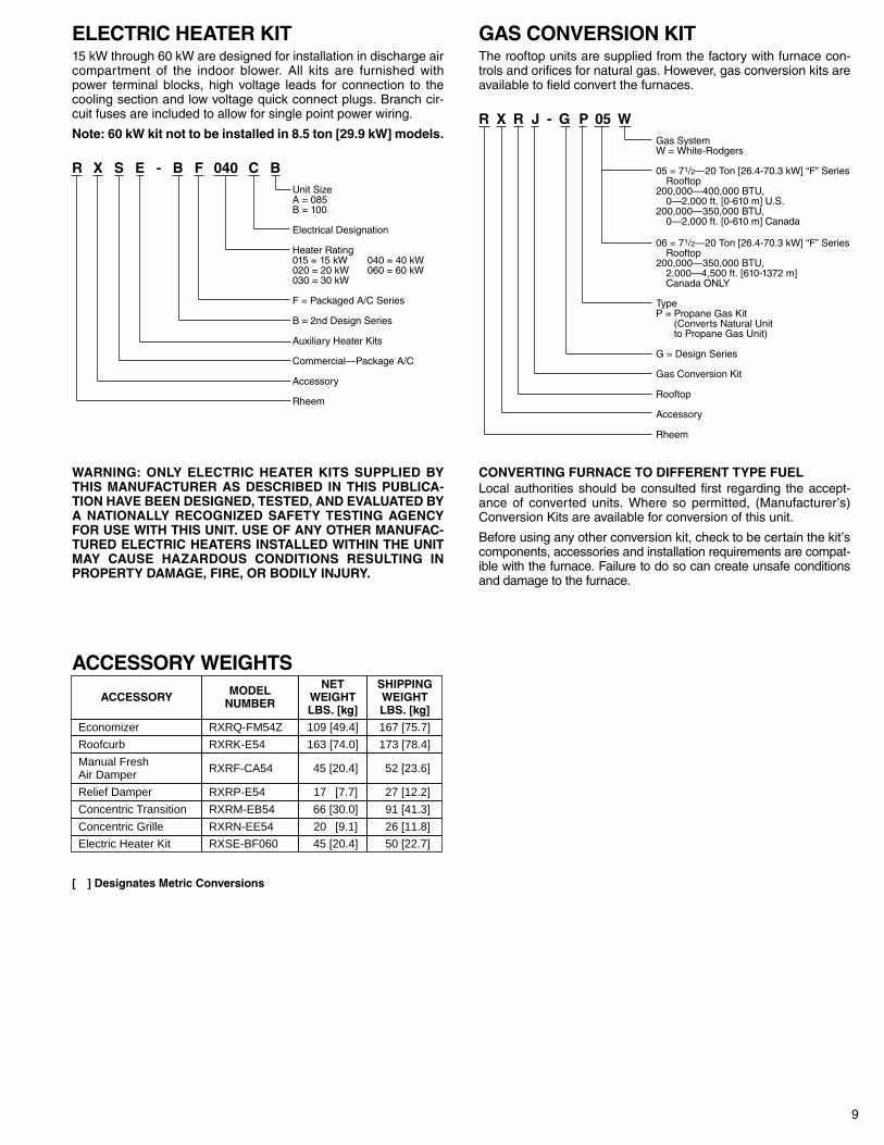
ELECTRIC HEATER KIT15 kW through 60 kW are designed for installation in discharge aircompartment of the indoor blower. All kits are furnished withpower terminal blocks, high voltage leads for connection to thecooling section and low voltage quick connect plugs. Branch cir-cuit fuses are included to allow for single point power wiring.
Note: 60 kW kit not to be installed in 8.5 ton [29.9 kW] models.
R X S E - B F 040 C BUnit SizeA = 085B = 100
Electrical Designation
Heater Rating015 = 15 kW 040 = 40 kW020 = 20 kW 060 = 60 kW030 = 30 kW
F = Packaged A/C Series
B = 2nd Design Series
Auxiliary Heater Kits
Commercial—Package A/C
Accessory
Rheem
WARNING: ONLY ELECTRIC HEATER KITS SUPPLIED BYTHIS MANUFACTURER AS DESCRIBED IN THIS PUBLICA-TION HAVE BEEN DESIGNED, TESTED, AND EVALUATED BYA NATIONALLY RECOGNIZED SAFETY TESTING AGENCYFOR USE WITH THIS UNIT. USE OF ANY OTHER MANUFAC-TURED ELECTRIC HEATERS INSTALLED WITHIN THE UNITMAY CAUSE HAZARDOUS CONDITIONS RESULTING INPROPERTY DAMAGE, FIRE, OR BODILY INJURY.
GAS CONVERSION KITThe rooftop units are supplied from the factory with furnace con-trols and orifices for natural gas. However, gas conversion kits areavailable to field convert the furnaces.
R X R J - G P 05 WGas SystemW = White-Rodgers
05 = 71/2—20 Ton [26.4-70.3 kW] “F” SeriesRooftop
200,000—400,000 BTU,0—2,000 ft. [0-610 m] U.S.
200,000—350,000 BTU,0—2,000 ft. [0-610 m] Canada
06 = 71/2—20 Ton [26.4-70.3 kW] “F” SeriesRooftop
200,000—350,000 BTU,2,000—4,500 ft. [610-1372 m]Canada ONLY
TypeP = Propane Gas Kit
(Converts Natural Unitto Propane Gas Unit)
G = Design Series
Gas Conversion Kit
Rooftop
Accessory
Rheem
CONVERTING FURNACE TO DIFFERENT TYPE FUELLocal authorities should be consulted first regarding the accept-ance of converted units. Where so permitted, (Manufacturer’s)Conversion Kits are available for conversion of this unit.
Before using any other conversion kit, check to be certain the kit’scomponents, accessories and installation requirements are compat-ible with the furnace. Failure to do so can create unsafe conditionsand damage to the furnace.
ACCESSORY WEIGHTS
ACCESSORY MODELNUMBER
NETWEIGHTLBS. [kg]
SHIPPINGWEIGHTLBS. [kg]
Economizer RXRQ-FM54Z 109 [49.4] 167 [75.7]
Roofcurb RXRK-E54 163 [74.0] 173 [78.4]
Manual FreshAir Damper RXRF-CA54 45 [20.4] 52 [23.6]
Relief Damper RXRP-E54 17 [7.7] 27 [12.2]
Concentric Transition RXRM-EB54 66 [30.0] 91 [41.3]
Concentric Grille RXRN-EE54 20 [9.1] 26 [11.8]
Electric Heater Kit RXSE-BF060 45 [20.4] 50 [22.7]
[ ] Designates Metric Conversions
10
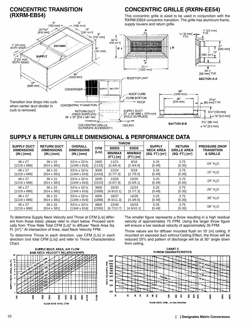
CONCENTRIC TRANSITION(RXRM-EB54)
CONCENTRIC GRILLE (RXRN-EE54)This concentric grille is sized to be used in conjunction with theRXRM-EB54 concentric transition. The grille has aluminum frame,supply louvers and return grille.
Transition box drops into curbwhen center duct divider incurb is removed.
SUPPLY DUCTDIMENSIONS
(IN.) [mm]
RETURN DUCTDIMENSIONS
(IN.) [mm]
OVERALLDIMENSIONS
(IN.) [mm]
CFM[L/s]
THROWSUPPLY
NECK AREA(SQ. FT.) [m2]
RETURNGRILLE AREA(SQ. FT.) [m2]
PRESSURE DROPTRANSITION
& GRILLE
SIDES ENDS
MIN/MAX(FT.) [m]
MIN/MAX(FT.) [m]
48 x 27[1219 x 686]
36 x 15[914 x 381]
531/8 x 321/8[1349 x 816]
2400[1133]
11/21[3.4/6.4]
8/16[2.4/4.9]
5.25[0.49]
3.75[0.35] .04" H2O
48 x 27[1219 x 686]
36 x 15[914 x 381]
531/8 x 321/8[1349 x 816]
3000[1416]
12/24[3.7/7.3]
9/18[2.7/5.5]
5.25[0.49]
3.75[0.35] .15" H2O
48 x 27[1219 x 686]
36 x 15[914 x 381]
531/8 x 321/8[1349 x 816]
3200[1510]
13/26[4.0/7.9]
10/20[3.0/6.1]
5.25[0.49]
3.75[0.35] .19" H2O
48 x 27[1219 x 686]
36 x 15[914 x 381]
531/8 x 321/8[1349 x 816]
3600[1699]
16/33[4.9/10.1]
12/24[3.7/7.3]
5.25[0.49]
3.75[0.35] .28" H2O
48 x 27[1219 x 686]
36 x 15[914 x 381]
531/8 x 321/8[1349 x 816]
4000[1888]
18/37[5.5/11.3]
14/28[4.3/8.5]
5.25[0.49]
3.75[0.35] .38" H2O
48 x 27[1219 x 686]
36 x 15[914 x 381]
531/8 x 321/8[1349 x 816]
4800[2265]
22/45[6.7/13.7]
16/33[4.9/10.1]
5.25[0.49]
3.75[0.35] .58" H2O
SUPPLY & RETURN GRILLE DIMENSIONAL & PERFORMANCE DATA
To determine Supply Neck Velocity and Throw at CFM [L/s] differ-ent from those listed, please refer to chart below. Proceed verti-cally from “Flow Rate Total CFM [L/s]” to diffuser “Neck Area Sq.Ft. [m2].” At intersection of lines, read Neck Velocity FPM.
To determine Throw in each direction, use CFM [L/s] in eachdirection (not total CFM [L/s]) and refer to Throw CharacteristicsChart.
The smaller figure represents a throw resulting in a high residualvelocity of approximately 75 FPM. Using the larger throw figurewill ensure a low residual velocity of approximately 35 FPM.
Throw values are for diffuser mounted flush on 10' [m] ceiling. Ifmounted on exposed duct without Ceiling Effect, the throw will bereduced 25% and pattern of discharge will be at 30° angle downfrom ceiling.
[ ] Designates Metric Conversions

11
PERFORMANCE RATINGSCOOLING RATED AND CERTIFIED WITHARI STANDARD 210
MODELCOOLINGCAPACITY
NET BTUH [kW]
STANDARDCFM [L/s]
EFFICIENCY
SOUNDBELS➀
EERBTUH/WATT[W/W]
IPLV
RRCF-085 102,000 [29.89] 3400 [1604.6] 9.0 [2.64] 9.0 9.0RREF-085 102,000 [29.89] 3400 [1604.6] 9.0 [2.64] 9.0 9.0RRGF-085 102,000 [29.89] 3400 [1604.6] 9.0 [2.64] 9.0 9.0RRCF-100 120,000 [35.17] 3900 [1840.6] 9.0 [2.64] 9.3 9.0RREF-100 120,000 [35.17] 3900 [1840.6] 9.0 [2.64] 9.3 9.0RRGF-100 120,000 [35.17] 3900 [1840.6] 9.0 [2.64] 9.3 9.0
MODEL
HEATING CAPACITYTHERMAL
EFFICIENCY(%)
AFUE(%)
HEATRISE
°F [°C] DB
INPUTBTUH[kW]
OUTPUTBTUH[kW]
RRGF-200085 200,000[58.61]
162,000[47.48] 81 79.5 30-60
[-1.1-15.6]
RRGF-200100 200,000[58.61]
162,000[47.48] 81 79.8 25-55
[-3.9-12.8]
RRGF-250100 250,000[73.27]
202,500[59.35] 81 79.6 30-60
[-1.1-15.6]
➀ In accordance with ARI Standard 270.NOTE: Deduct 2000 BTUH from [0.59 kW] 100 model for net cooling
capacity at 208 volts.
NOTE: Output capacity rated in accordance with ANSI-Z21.47.
ELECTRIC HEATING (8.5 Ton [29.9 kW] Models)
MODELHEATING OUTPUT
BTUH [kW]1ST STAGE
HEATING OUTPUTBTUH [kW]2ND STAGE
HEATING OUTPUTBTUH [kW]
TOTAL
TEMPERATURE RISE °F [°C] @ CFM [L/s]2600
[1227]3000[1416]
3400[1605]
3800[1793]
4200[1982]
RREF-015085C 24,574 [7.20] 24,574 [7.20] 49,148 [14.40] 18 [10.0] 15 [8.3] 13 [7.2] 12 [6.7] 11 [6.1]RREF-020085C 34,096 [9.99] 34,096 [9.99] 68,192 [19.99] 24 [13.3] 21 [11.7] 19 [10.6] 17 [9.4] 15 [8.3]RREF-030085C 49,147 [14.40] 49,147 [14.40] 98,294 [28.81] 35 [19.4] 30 [16.7] 27 [15.0] 24 [13.3] 22 [12.2]RREF-040085C 68,192 [19.99] 68,192 [19.99] 136,384 [39.97] 49 [27.2] 42 [23.3] 37 [20.6] 33 [18.3] 30 [16.7]RREF-015085D 24,574 [7.20] 24,574 [7.20] 49,148 [14.40] 18 [10.0] 15 [8.3] 13 [7.2] 12 [6.7] 11 [6.1]RREF-020085D 34,096 [9.99] 34,096 [9.99] 68,192 [19.99] 24 [13.3] 21 [11.7] 19 [10.6] 17 [9.4] 15 [8.3]RREF-030085D 49,147 [14.40] 49,147 [14.40] 98,294 [28.81] 35 [19.4] 30 [16.7] 27 [15.0] 24 [13.3] 22 [12.2]RREF-040085D 68,192 [19.99] 68,192 [19.99] 136,384 [39.97] 49 [27.2] 42 [23.3] 37 [20.6] 33 [18.3] 30 [16.7]RREF-020085Y 34,130 [10.00] 34,130 [10.00] 68,260 [20.01] 24 [13.3] 21 [11.7] 19 [10.6] 17 [9.4] 15 [8.3]RREF-040085Y 68,260 [20.01] 68,260 [20.01] 136,520 [40.01] 49 [27.2] 42 [23.3] 38 [21.1] 34 [18.9] 30 [16.7]
ELECTRIC HEATING (10 Ton [35.2 kW] Models)
MODELHEATING OUTPUT
BTUH [kW]1ST STAGE
HEATING OUTPUTBTUH [kW]2ND STAGE
HEATING OUTPUTBTUH [kW]
TOTAL
TEMPERATURE RISE °F [°C] @ CFM [L/s]3200[1510]
3600[1699]
4000[1888]
4400[2077]
4800[2265]
RREF-015100C 24,574 [7.20] 24,574 [7.20] 49,148 [14.40] 14 [7.8] 13 [7.2] 11 [6.1] 10 [5.6] 9 [5.0]RREF-020100C 34,096 [9.99] 34,096 [9.99] 68,192 [19.99] 20 [11.1] 18 [10.0] 16 [8.9] 14 [7.8] 13 [7.2]RREF-030100C 49,147 [14.40] 49,147 [14.40] 98,294 [28.81] 28 [15.6] 25 [13.9] 23 [12.8] 21 [11.7] 19 [10.6]RREF-040100C 68,192 [19.99] 68,192 [19.99] 136,384 [39.97] 39 [21.7] 36 [20.0] 32 [17.8] 29 [16.1] 26 [14.4]RREF-060100C 98,295 [28.81] 98,295 [28.81] 196,590 [57.61] 57 [31.7] 51 [28.3] 46 [25.6] 41 [22.8] 38 [21.1]RREF-015100D 24,574 [7.20] 24,574 [7.20] 49,148 [14.40] 14 [7.8] 13 [7.2] 11 [6.1] 10 [5.6] 9 [5.0]RREF-020100D 34,096 [9.99] 34,096 [9.99] 68,192 [19.99] 20 [11.1] 18 [10.0] 16 [8.9] 14 [7.8] 13 [7.2]RREF-030100D 49,147 [14.40] 49,147 [14.40] 98,294 [28.81] 28 [15.6] 25 [13.9] 23 [12.8] 21 [11.7] 19 [10.6]RREF-040100D 68,192 [19.99] 68,192 [19.99] 136,384 [39.97] 39 [21.7] 36 [20.0] 32 [17.8] 29 [16.1] 26 [14.4]RREF-060100D 98,295 [28.81] 98,295 [28.81] 196,590 [57.61] 57 [31.7] 51 [28.3] 46 [25.6] 41 [22.8] 38 [21.1]RREF-030100Y 49,148 [14.40] 49,148 [14.40] 98,295 [28.81] 14 [7.8] 13 [7.2] 11 [6.1] 10 [5.6] 9 [5.0]RREF-060100Y 98,295 [28.81] 98,295 [28.81] 196,590 [57.61] 57 [31.7] 51 [28.3] 46 [25.6] 41 [22.8] 38 [21.1]
NOTE: Electric heat output rated at 240 volts on “C” voltage units, 480 volts on “D” voltage units, and 600 volts on “Y” voltage units.
NOTE: Electric heat output rated at 240 volts on “C” voltage units, 480 volts on “D” voltage units, and 600 volts on “Y” voltage units.
HEATING TEMPERATURE RISE HEATING CORRECTION FACTOR
HEATING CORRECTION FACTOR
For correction of unit output, multiply the correction factor times the unitrating in BTU if actual supply voltage differs from rated voltage.
Blower watts not included in heater ratings. Refer to Blower Table for wattson a particular job and multiply by 3.413 to obtain BTUH [kW] adder.
[ ] Designates Metric ConversionsFor correction of unit output, multiply the correction factor times thekW rating at 600V.
FORMULA: TEMP. RISE. °F [°C] = 3160 x kWCFM [L/s]
3160 = CONSTANTkW = kW RATING OF UNITCFM [L/s] =AIR FLOW AT SPECIFIED CONDITIONS
GAS HEATING
12
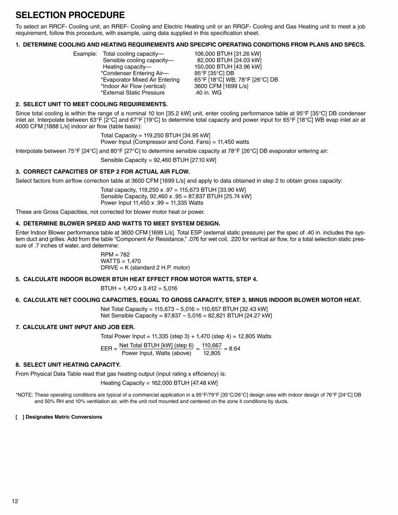
SELECTION PROCEDURETo select an RRCF- Cooling unit, an RREF- Cooling and Electric Heating unit or an RRGF- Cooling and Gas Heating unit to meet a jobrequirement, follow this procedure, with example, using data supplied in this specification sheet.
1. DETERMINE COOLING AND HEATING REQUIREMENTS AND SPECIFIC OPERATING CONDITIONS FROM PLANS AND SPECS.
Example: *Total cooling capacity— 106,000 BTUH [31.26 kW]*Sensible cooling capacity— 82,000 BTUH [24.03 kW]*Heating capacity— 150,000 BTUH [43.96 kW]*Condenser Entering Air— 95°F [35°C] DB*Evaporator Mixed Air Entering 65°F [18°C] WB; 78°F [26°C] DB*Indoor Air Flow (vertical) 3600 CFM [1699 L/s]*External Static Pressure .40 in. WG
2. SELECT UNIT TO MEET COOLING REQUIREMENTS.
Since total cooling is within the range of a nominal 10 ton [35.2 kW] unit, enter cooling performance table at 95°F [35°C] DB condenserinlet air. Interpolate between 63°F [2°C] and 67°F [19°C] to determine total capacity and power input for 65°F [18°C] WB evap inlet air at4000 CFM [1888 L/s] indoor air flow (table basis):
Total Capacity = 119,250 BTUH [34.95 kW]Power Input (Compressor and Cond. Fans) = 11,450 watts
Interpolate between 75°F [24°C] and 80°F [27°C] to determine sensible capacity at 78°F [26°C] DB evaporator entering air:
Sensible Capacity = 92,460 BTUH [27.10 kW]
3. CORRECT CAPACITIES OF STEP 2 FOR ACTUAL AIR FLOW.
Select factors from airflow correction table at 3600 CFM [1699 L/s] and apply to data obtained in step 2 to obtain gross capacity:
Total capacity, 119,250 x .97 = 115,673 BTUH [33.90 kW]Sensible Capacity, 92,460 x .95 = 87,837 BTUH [25.74 kW]Power Input 11,450 x .99 = 11,335 Watts
These are Gross Capacities, not corrected for blower motor heat or power.
4. DETERMINE BLOWER SPEED AND WATTS TO MEET SYSTEM DESIGN.
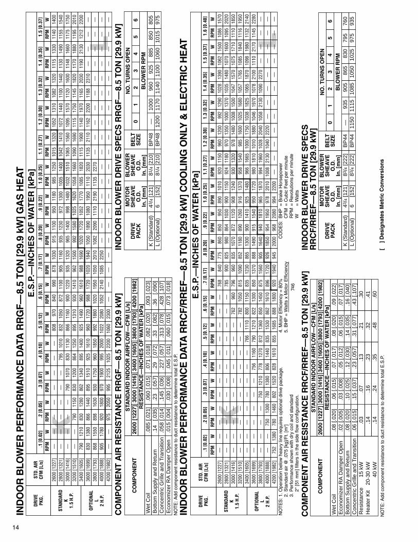
Enter Indoor Blower performance table at 3600 CFM [1699 L/s]. Total ESP (external static pressure) per the spec of .40 in. includes the sys-tem duct and grilles. Add from the table “Component Air Resistance,” .076 for wet coil, .220 for vertical air flow, for a total selection static pres-sure of .7 inches of water, and determine:
RPM = 782WATTS = 1,470DRIVE = K (standard 2 H.P. motor)
5. CALCULATE INDOOR BLOWER BTUH HEAT EFFECT FROM MOTOR WATTS, STEP 4.
BTUH = 1,470 x 3.412 = 5,016
6. CALCULATE NET COOLING CAPACITIES, EQUAL TO GROSS CAPACITY, STEP 3, MINUS INDOOR BLOWER MOTOR HEAT.
Net Total Capacity = 115,673 – 5,016 = 110,657 BTUH [32.43 kW]Net Sensible Capacity = 87,837 – 5,016 = 82,821 BTUH [24.27 kW]
7. CALCULATE UNIT INPUT AND JOB EER.
Total Power Input = 11,335 (step 3) + 1,470 (step 4) = 12,805 Watts
EER = Net Total BTUH [kW] (step 6) = 110,667 = 8.64Power Input, Watts (above) 12,805
8. SELECT UNIT HEATING CAPACITY.
From Physical Data Table read that gas heating output (input rating x efficiency) is:
Heating Capacity = 162,000 BTUH [47.48 kW]
*NOTE: These operating conditions are typical of a commercial application in a 95°F/79°F [35°C/26°C] design area with indoor design of 76°F [24°C] DBand 50% RH and 10% ventilation air, with the unit roof mounted and centered on the zone it conditions by ducts.
[ ] Designates Metric Conversions
13
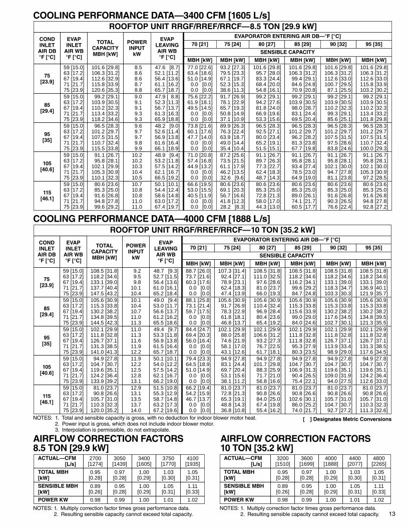
COOLING PERFORMANCE DATA—3400 CFM [1605 L/s]
COOLING PERFORMANCE DATA—4000 CFM [1888 L/s]
AIRFLOW CORRECTION FACTORS8.5 TON [29.9 kW]
AIRFLOW CORRECTION FACTORS10 TON [35.2 kW]
NOTES: 1. Total and sensible capacity is gross, with no deduction for indoor blower motor heat. [ ] Designates Metric Conversions2. Power input is gross, which does not include indoor blower motor.3. Interpolation is permissible, do not extrapolate.
NOTES: 1. Multiply correction factor times gross performance data.2. Resulting sensible capacity cannot exceed total capacity.
ROOFTOP UNIT RRGF/RREF/RRCF—8.5 TON [29.9 kW]
POWERINPUT
kW
EVAPLEAVINGAIR WB°F [°C]
CONDINLET
AIR DB°F [°C]
EVAPINLET
AIR WB°F [°C]
EVAPORATOR ENTERING AIR DB—°F [°C]TOTAL
CAPACITYMBH [kW]
70 [21] 75 [24] 80 [27] 85 [29] 90 [32] 95 [35]
8.58.68.68.78.8
47.6 [8.7]52.1 [11.2]56.4 [13.6]61.1 [16.2]65.7 [18.7]
75[23.9]
59 [15.0]63 [17.2]67 [19.4]71 [21.7]75 [23.9]
77.0 [22.6]63.4 [18.6]51.0 [14.9]
0.0 [0.0]0.0 [0.0]
101.6 [29.8]106.3 [31.2]112.6 [32.9]115.8 [33.9]120.6 [35.3]
93.2 [27.3]79.5 [23.3]67.1 [19.7]52.3 [15.3]38.6 [11.3]
101.6 [29.8]95.7 [28.0]83.3 [24.4]68.4 [20.0]54.8 [16.1]
101.6 [29.8]106.3 [31.2]
99.4 [29.1]84.6 [24.8]70.9 [20.8]
101.6 [29.8]106.3 [31.2]112.6 [33.0]100.7 [29.5]
87.1 [25.5]
101.6 [29.8]106.3 [31.2]112.6 [33.0]115.8 [33.9]103.2 [30.2]
SENSIBLE CAPACITY
MBH [kW] MBH [kW] MBH [kW] MBH [kW] MBH [kW] MBH [kW]
9.09.19.19.39.3
47.9 [ 8.8]52.3 [11.3]56.7 [13.7]61.3 [16.3]65.9 [18.8]
85[29.4]
59 [15.0]63 [17.2]67 [19.4]71 [21.7]75 [23.9]
75.6 [22.2]61.9 [18.1]49.5 [14.5]
0.0 [0.0]0.0 [0.0]
99.2 [29.1]103.9 [30.5]110.2 [32.3]113.4 [33.2]118.2 [34.6]
91.7 [26.9]78.1 [22.9]65.7 [19.3]50.8 [14.9]37.1 [10.9]
99.2 [29.1]94.2 [27.6]81.8 [24.0]66.9 [19.6]53.3 [15.6]
99.2 [29.1]103.9 [30.5]
98.0 [28.7]83.1 [24.4]69.5 [20.4]
99.2 [29.1]103.9 [30.5]110.2 [32.3]
99.3 [29.1]85.6 [25.1]
99.2 [29.1]103.9 [30.5]110.2 [32.3]113.4 [33.2]101.8 [29.8]
10.210.210.310.410.5
48.9 [9.4]53.2 [11.8]57.5 [14.2]62.1 [16.7]66.5 [19.2]
105[40.6]
59 [15.0]63 [17.2]67 [19.4]71 [21.7]75 [23.9]
71.0 [20.8]57.4 [16.8]44.9 [13.2]
0.0 [0.0]0.0 [0.0]
91.1 [26.7]95.8 [28.1]
102.1 [29.9]105.3 [30.9]110.1 [32.3]
87.2 [25.6]73.5 [21.5]61.1 [17.9]46.2 [13.5]32.6 [9.6]
91.1 [26.7]89.7 [26.3]77.3 [22.7]62.4 [18.3]48.7 [14.3]
91.1 [26.7]95.8 [28.1]93.4 [27.4]78.5 [23.0]64.9 [19.0]
91.1 [26.7]95.8 [28.1]
102.1 [30.0]94.7 [27.8]81.1 [23.8]
91.1 [26.7]95.8 [28.1]
102.1 [30.0]105.3 [30.9]
97.2 [28.5]
9.69.79.79.89.9
48.2 [9.0]52.6 [11.4]56.9 [13.8]61.6 [16.4]66.1 [18.9]
95[35]
59 [15.0]63 [17.2]67 [19.4]71 [21.7]75 [23.9]
73.8 [21.6]60.1 [17.6]47.7 [14.0]
0.0 [0.0]0.0 [0.0]
96.5 [28.3]101.2 [29.7]107.5 [31.5]110.7 [32.4]115.5 [33.8]
89.9 [26.3]76.3 [22.4]63.9 [18.7]49.0 [14.4]35.4 [10.4]
96.5 [28.3]92.5 [27.1]80.0 [23.4]65.2 [19.1]51.5 [15.1]
96.5 [28.3]101.2 [29.7]
96.2 [28.2]81.3 [23.8]67.7 [19.8]
96.5 [28.3]101.2 [29.7]107.5 [31.5]
97.5 [28.6]83.8 [24.6]
96.5 [28.3]101.2 [29.7]107.5 [31.5]110.7 [32.4]100.0 [29.3]
10.710.810.811.011.0
50.1 [10.1]54.4 [12.4]58.6 [14.8]63.0 [17.2]67.4 [19.7]
115[46.1]
59 [15.0]63 [17.2]67 [19.4]71 [21.7]75 [23.9]
66.6 [19.5]53.0 [15.5]40.5 [11.9]
0.0 [0.0]0.0 [0.0]
80.6 [23.6]85.3 [25.0]91.6 [26.8]94.8 [27.8]99.6 [29.2]
80.6 [23.6]69.1 [20.3]56.7 [16.6]41.8 [12.3]28.2 [8.3]
80.6 [23.6]85.3 [25.0]72.8 [21.3]58.0 [17.0]44.3 [13.0]
80.6 [23.6]85.3 [25.0]89.0 [26.1]74.1 [21.7]60.5 [17.7]
80.6 [23.6]85.3 [25.0]91.6 [26.8]90.3 [26.5]76.6 [22.4]
80.6 [23.6]85.3 [25.0]91.6 [26.8]94.8 [27.8]92.8 [27.2]
ROOFTOP UNIT RRGF/RREF/RRCF—10 TON [35.2 kW]
POWERINPUT
kW
EVAPLEAVINGAIR WB°F [°C]
CONDINLET
AIR DB°F [°C]
EVAPINLET
AIR WB°F [°C]
EVAPORATOR ENTERING AIR DB—°F [°C]TOTAL
CAPACITYMBH [kW]
70 [21] 75 [24] 80 [27] 85 [29] 90 [32] 95 [35]
9.29.59.8
10.110.4
48.7 [9.3]52.7 [11.5]56.4 [13.6]61.0 [16.1]65.2 [18.4]
75[23.9]
59 [15.0]63 [17.2]67 [19.4]71 [21.7]75 [23.9]
88.7 [26.0]73.7 [21.6]60.3 [17.6]
0.0 [0.0]0.0 [0.0]
108.5 [31.8]118.2 [34.6]133.1 [39.0]137.7 [40.4]147.5 [43.2]
107.3 [31.4]92.4 [27.1]78.9 [23.1]62.4 [18.3]47.4 [13.9]
108.5 [31.8]111.0 [32.5]
97.6 [28.6]81.0 [23.7]66.0 [19.3]
108.5 [31.8]118.2 [34.6]116.2 [34.1]
99.6 [29.2]84.7 [24.8]
108.5 [31.8]118.2 [34.6]133.1 [39.0]118.3 [34.7]103.3 [30.3]
108.5 [31.8]118.2 [34.6]133.1 [39.0]136.9 [40.1]121.9 [35.7]
SENSIBLE CAPACITY
MBH [kW] MBH [kW] MBH [kW] MBH [kW] MBH [kW] MBH [kW]
10.110.410.711.011.3
49.0 [9.4]53.0 [11.7]56.6 [13.7]61.2 [16.2]65.5 [18.6]
85[29.4]
59 [15.0]63 [17.2]67 [19.4]71 [21.7]75 [23.9]
88.1 [25.8]73.1 [21.4]59.7 [17.5]
0.0 [0.0]0.0 [0.0]
105.6 [30.9]115.3 [33.8]130.2 [38.2]134.8 [39.5]144.5 [42.3]
105.6 [30.9]91.7 [26.9]78.3 [22.9]61.8 [18.1]46.8 [13.7]
105.6 [30.9]110.4 [32.4]
96.9 [28.4]80.4 [23.6]65.4 [19.2]
105.6 [30.9]115.3 [33.8]115.6 [33.9]
99.0 [29.0]84.0 [24.6]
105.6 [30.9]115.3 [33.8]130.2 [38.2]117.6 [34.5]102.7 [30.1]
105.6 [30.9]115.3 [33.8]130.2 [38.2]134.8 [39.5]121.3 [35.5]
11.912.212.512.813.1
50.1 [10.1]54.0 [12.2]57.5 [14.2]62.1 [16.7]66.2 [19.0]
105[40.6]
59 [15.0]63 [17.2]67 [19.4]71 [21.7]75 [23.9]
79.4 [23.3]64.5 [18.9]51.0 [14.9]
0.0 [0.0]0.0 [0.0]
94.9 [27.8]104.7 [30.7]119.6 [35.1]124.2 [36.4]133.9 [39.2]
94.9 [27.8]83.1 [24.4]69.7 [20.4]53.1 [15.6]38.1 [11.2]
94.9 [27.8]101.7 [29.8]
88.3 [25.9]71.7 [21.0]56.8 [16.6]
94.9 [27.8]104.7 [30.7]106.9 [31.3]
90.4 [26.5]75.4 [22.1]
94.9 [27.8]104.7 [30.7]119.6 [35.1]109.0 [31.9]
94.0 [27.5]
94.9 [27.8]104.7 [30.7]119.6 [35.1]124.2 [36.4]112.6 [33.0]
11.011.311.611.912.2
49.4 [9.7]53.3 [11.8]56.9 [13.8]61.5 [16.4]65.7 [18.7]
95[35]
59 [15.0]63 [17.2]67 [19.4]71 [21.7]75 [23.9]
84.4 [24.7]69.4 [20.3]56.0 [16.4]
0.0 [0.0]0.0 [0.0]
102.1 [29.9]111.8 [32.8]126.7 [37.1]131.3 [38.5]141.0 [41.3]
102.1 [29.9]88.0 [25.8]74.6 [21.9]58.1 [17.0]43.1 [12.6]
102.1 [29.9]106.6 [31.2]
93.2 [27.3]76.7 [22.5]61.7 [18.1]
102.1 [29.9]111.8 [32.8]111.8 [32.8]
95.3 [27.9]80.3 [23.5]
102.1 [29.9]111.8 [32.8]126.7 [37.1]113.9 [33.4]
98.9 [29.0]
102.1 [29.9]111.8 [32.8]126.7 [37.1]131.3 [38.5]117.6 [34.5]
12.913.113.513.714.0
51.5 [10.8]55.3 [12.9]58.7 [14.8]63.2 [17.3]67.2 [19.6]
115[46.1]
59 [15.0]63 [17.2]67 [19.4]71 [21.7]75 [23.9]
66.2 [19.4]54.2 [15.9]46.7 [13.7]
0.0 [0.0]0.0 [0.0]
81.0 [23.7]90.8 [26.6]
105.7 [31.0]110.3 [32.3]120.0 [35.2]
81.0 [23.7]72.8 [21.3]65.3 [19.1]48.8 [14.3]36.8 [10.8]
81.0 [23.7]90.8 [26.6]84.0 [25.0]67.4 [19.8]55.4 [16.2]
81.0 [23.7]90.8 [26.6]
102.6 [30.1]86.0 [25.2]74.0 [21.7]
81.0 [23.7]90.8 [26.6]
105.7 [31.0]104.7 [30.7]
92.7 [27.2]
81.0 [23.7]90.8 [26.6]
105.7 [31.0]110.3 [32.3]111.3 [32.6]
ACTUAL—CFM [L/s]
2700[1274]
3050[1439]
3750[1770]
4100[1935]
TOTAL MBH[kW]
0.95[0.28]
0.97[0.28]
1.03[0.30]
1.05[0.31]
SENSIBLE MBH[kW]
0.89[0.26]
0.95[0.28]
1.05[0.31]
1.11[0.33]
POWER KW 0.98 0.99 1.01 1.02
3400[1605]
1.00[0.29]
1.00[0.29]
1.00
ACTUAL—CFM [L/s]
3200[1510]
3600[1699]
4000[1888]
4400[2077]
TOTAL MBH[kW]
0.95[0.28]
0.97[0.28]
1.00[0.29]
1.03[0.30]
SENSIBLE MBH[kW]
0.89[0.26]
0.95[0.28]
1.00[0.29]
1.05[0.31]
POWER KW 0.98 0.99 1.00 1.01
4800[2265]
1.05[0.31]
1.11[0.33]
1.02
NOTES: 1. Multiply correction factor times gross performance data.2. Resulting sensible capacity cannot exceed total capacity.
14
NO
TE
S: 1
. Ope
ratio
n be
low
hea
vy li
ne r
equi
res
optio
nal d
rive
pack
age.
2. S
tand
ard
air
@ .0
75 [k
g]/F
t. [m
3 ]3.
Per
form
ance
sho
wn
with
dry
coi
l and
sta
ndar
d 2"
[51
mm
] filt
ers
in th
e si
de fl
ow c
onfig
urat
ion.
IND
OO
R B
LOW
ER
PE
RFO
RM
AN
CE
DA
TAR
RG
F—8.
5 TO
N [2
9.9
kW] G
AS
HE
AT
NO
TE
:Add
com
pone
nt r
esis
tanc
e to
duc
t res
ista
nce
to d
eter
min
e to
tal E
.S.P
.
NO
TE
: Add
com
pone
nt r
esis
tanc
e to
duc
t res
ista
nce
to d
eter
min
e to
tal E
.S.P
.
CO
MP
ON
EN
T A
IR R
ES
ISTA
NC
E R
RG
F—
8.5
TON
[29.
9 kW
]IN
DO
OR
BLO
WE
R D
RIV
E S
PE
CS
RR
GF
—8.
5 TO
N [2
9.9
kW]
CO
MP
ON
EN
TA
IRR
ES
ISTA
NC
E R
RC
F/R
RE
F—
8.5
TON
[29.
9 kW
]IN
DO
OR
BLO
WE
R D
RIV
E S
PE
CS
R
RC
F/R
RE
F—
8.5
TON
[29.
9 kW
]
IND
OO
R B
LOW
ER
PE
RFO
RM
AN
CE
DA
TA R
RC
F/R
RE
F—8.
5 TO
N [2
9.9
kW] C
OO
LIN
G O
NLY
& E
LEC
TRIC
HE
ATL
KDR
IVE
PKG.
STD.
AIR
CFM
[L/s
]
E.S
.P.—
INC
HE
S O
F W
AT
ER
[kP
a].1
[0.0
2].2
[0.0
5].3
[0.0
7].4
[0.1
0]RP
MW
RPM
WRP
MW
RPM
W
3200
[151
0]—
—79
011
5083
012
0086
412
5034
00 [1
605]
790
1210
830
1280
862
1340
895
1400
3600
[169
9]83
013
8086
614
4089
515
1092
516
1038
00 [1
793]
868
1550
898
1630
930
1750
960
1850
4000
[188
8]90
517
8092
018
0097
019
0099
520
00
.5 [0
.12]
.6 [0
.15]
.7 [0
.17]
.8 [0
.20]
RPM
WRP
MW
RPM
WRP
MW
895
1310
930
1410
962
1500
992
1580
925
1490
960
1610
988
1690
1020
1720
960
1720
988
1720
1020
1840
1050
1890
992
1860
1020
1950
1050
2010
1082
2090
1022
2080
1052
2140
1085
2250
——
1.3
[0.3
2]1.
4 [0
.35]
1.5
[0.3
7]RP
MW
RPM
WRP
MW
1145
1820
1170
1880
1195
2010
1165
2030
1190
2130
1212
2200
1188
2310
——
——
——
——
——
——
——
——
.9 [0
.22]
1.0
[0.2
5]1.
1 [0
.27]
1.2
[0.3
0]RP
MW
RPM
WRP
MW
RPM
W
1025
1620
1058
1660
1090
1690
1115
1750
1052
1770
1085
1820
1115
1900
1140
1970
1080
1950
1110
2030
1135
2110
1162
2200
1110
2190
1135
2270
——
——
——
——
——
——
808
970
840
990
878
1030
915
1100
832
1050
872
1100
905
1160
935
1230
866
1160
900
1220
935
1320
965
1400
1082
1320
1115
1330
1140
1400
1100
1440
1130
1490
1155
1540
1120
1600
1148
1660
1175
1750
STAN
DARD
K1.
5 H.
P.
2600
[122
7]—
——
——
——
—95
011
8098
512
5010
1513
2010
5228
00 [1
321]
——
——
——
795
1010
1310
972
1300
1005
1400
1042
1410
1072
1440
998
1480
1032
1510
1065
1560
1095
1570
3000
[141
6]—
——
—79
010
7083
011
30
1060
2300
——
——
——
——
——
——
——
——
——
——
4200
[198
2]—
—97
520
5099
521
2510
2522
00
OPTI
ONAL
L2
H.P.
KL
.5 [0
.12]
.6 [0
.15]
.7 [0
.17]
.8 [0
.20]
RPM
WRP
MW
RPM
WRP
MW
——
——
768
840
775
860
——
——
785
900
825
980
——
762
960
796
960
835
1070
——
782
1050
815
1090
852
1180
766
1110
800
1150
835
1230
865
1300
1.3
[0.3
2]1.
4 [0
.35]
1.5
[0.3
7]1.
6 [0
.40]
RPM
WRP
MW
RPM
WRP
MW
992
1290
1028
1390
1062
1500
1086
1570
1000
1370
1035
1480
1070
1600
DRIV
EPK
G.ST
D. A
IRCF
M [L
/s]
E.S
.P.—
INC
HE
S O
F W
AT
ER
[kP
a]
1095
2020
1008
1500
1047
1570
1075
1710
1110
1850
1025
1680
1057
1765
1085
1840
1116
1950
1038
1825
1065
1870
1098
1980
1132
2140
.1 [0
.02]
.2 [0
.05]
.3 [0
.07]
.4 [0
.10]
.9 [0
.22]
1.0
[0.2
5]1.
1 [0
.27]
1.2
[0.3
0]
RPM
WRP
MW
RPM
WRP
MW
850
950
890
1010
920
1150
960
1200
864
1030
900
1150
924
1180
970
1350
RPM
WRP
MW
RPM
WRP
MW
872
1120
908
1240
930
1320
978
1480
890
1260
916
1370
958
1540
985
1600
900
1410
925
1480
966
1665
1000
1750
2600
[122
7]—
——
——
——
—28
00 [1
321]
——
——
——
——
3000
[141
6]—
——
——
——
—32
00 [1
510]
——
——
——
——
3400
[160
5]—
——
——
——
—
STAN
DARD
K1.
5 H.
P.
790
1210
822
1300
850
1370
888
1490
812
1360
850
1450
875
1560
905
1640
835
1530
862
1610
896
1720
926
1850
1046
1970
1078
2100
1110
2170
1145
2280
1058
2130
1090
2270
——
——
——
——
——
——
915
1540
950
1720
980
1810
1010
1880
940
1810
965
1870
994
1960
1028
2040
954
1950
978
2010
1008
2130
1040
2220
3600
[169
9]—
——
——
—75
611
6038
00 [1
793]
——
——
750
1210
778
1270
4000
[188
8]—
—75
013
0078
013
8080
614
4085
516
8588
818
0092
019
4094
520
00—
——
——
——
—96
820
8099
422
00—
——
—42
00 [1
982]
752
1380
780
1460
802
1520
828
1610
OPTI
ONAL
L2
H.P.
RE
SIS
TAN
CE
—IN
CH
ES
OF
WA
TE
R [
kPa]
Bot
tom
Sup
ply
and
Ret
urn
.14
[.035
]C
once
ntric
Gril
le a
nd T
rans
ition
.058
[.01
4]
CO
MP
ON
EN
TS
TAN
DA
RD
IND
OO
R A
IRF
LOW
—C
FM
[L
/s]
2600
[12
27]
3000
[14
16]
.145
[.03
6].2
3 [.0
57]
.29
[.072
].2
27 [.
057]
3400
[16
05]
3800
[17
93]
.313
[.07
8].3
3 [.0
82]
4200
[19
82]
.428
[.10
7].3
6 [.0
90]
.071
[.01
8].0
82 [.
020]
Wet
Coi
l.0
85 [.
021]
.093
[.02
3].0
60 [.
015]
Eco
nom
izer
RA
Dam
per
Ope
n.0
45 [.
011]
.015
[.00
4].0
60 [.
015]
.073
[.01
8].0
30 [.
008]
MO
TO
RS
HE
AV
EO
.D.
In. [
mm
]
DR
IVE
PA
CK
BLO
WE
RS
HE
AV
EO
.D.
In. [
mm
]
BE
LTS
IZE
NO
. TU
RN
SO
PE
N5
01
23
4
850
81/4
[210
]B
P48
43/4
[121
]K
(S
tand
ard)
—10
0096
092
588
5B
LOW
ER
RP
M
1015
81/4
[210
]B
P48
63/4
[152
]L
(Opt
iona
l)12
0011
7011
4011
0010
60
6 975
805
4. M
otor
Effi
cien
cy =
80%
5. B
HP
= W
atts
x M
otor
Effi
cien
cy74
6
CO
DE
S:
BH
P=
Bra
ke H
orse
pow
erC
FM
= C
ubic
Fee
t per
min
ute
RP
M=
Rev
olut
ions
per
min
ute
W=
Wat
ts
RE
SIS
TAN
CE
—IN
CH
ES
OF
WA
TE
R [
kPa]
Bot
tom
Sup
ply
and
Ret
urn
.08
[.020
]C
once
ntric
Gril
le a
nd T
rans
ition
.06
[.015
]
CO
MP
ON
EN
TS
TAN
DA
RD
IND
OO
R A
IRF
LOW
—C
FM
[L
/s]
2600
[12
27]
3000
[14
16]
.15
[.037
].1
0 [.0
25]
.12
[.030
].2
3 [.0
57]
3400
[16
05]
3800
[17
93]
.31
[.077
].1
4 [.0
35]
4200
[19
82]
.43
[.107
].1
6 [.0
40]
.07
[.017
].0
8 [.0
20]
Wet
Coi
l.0
8 [.0
20]
.09
[.022
].0
6 [.0
15]
Eco
nom
izer
RA
Dam
per
Ope
n.0
5 [.0
12]
.02
[.005
].0
6 [.0
15]
.07
[.017
].0
3 [.0
08]
Res
ista
nce
15 k
WH
eate
r K
it20
-30
kW40
kW
.13
.03
.21
.30
.23
.32
.14
.41
.16
.07
.35
.48
.14
.60
.24
MO
TO
RS
HE
AV
EO
.D.
In. [
mm
]
DR
IVE
PA
CK
BLO
WE
RS
HE
AV
EO
.D.
In. [
mm
]
BE
LTS
IZE
NO
. TU
RN
SO
PE
N5
01
23
4
795
83/4
[222
]B
P44
43/4
[121
]K
(S
tand
ard)
—93
590
586
583
0B
LOW
ER
RP
M
975
83/4
[222
]B
P44
63/4
[152
]L
(Opt
iona
l)11
5011
1510
8510
5010
25
6 935
760
[]
Des
ign
ates
Met
ric
Co
nver
sio
ns
15
MO
TO
RS
HE
AV
EO
.D.
In. [
mm
]
DR
IVE
PA
CK
BLO
WE
RS
HE
AV
EO
.D.
In. [
mm
]
BE
LTS
IZE
NO
. TU
RN
SO
PE
N5
01
23
4
715
93/4
[248
]B
P55
43/4
[121
]K
(S
tand
ard)
—84
081
078
075
0B
LOW
ER
RP
M
855
93/4
[248
]B
P55
63/4
[152
]L
(Opt
iona
l)10
1098
095
092
089
0
6 820
685
L
KDR
IVE
PKG.
STD.
AIR
CFM
[L/s
]
E.S
.P.—
INC
HE
S O
F W
AT
ER
[kP
a].1
[0.0
2].2
[0.0
5].3
[0.0
7].4
[0.1
0]RP
MW
RPM
WRP
MW
RPM
W
3800
[179
3]—
——
—70
013
5072
414
2040
00 [1
888]
——
696
1420
720
1490
746
1570
4200
[198
2]69
615
2072
015
9074
816
8077
617
7044
00 [2
077]
720
1700
748
1780
776
1880
804
2000
4600
[217
1]75
219
2078
020
1081
021
4081
820
50
.5 [0
.12]
.6 [0
.15]
.7 [0
.17]
.8 [0
.20]
RPM
WRP
MW
RPM
WRP
MW
752
1490
776
1560
802
1620
826
1670
774
1660
800
1730
824
1790
846
1870
800
1850
824
1930
850
1910
872
1990
818
1940
846
2020
870
2110
894
2220
848
2150
870
2250
894
2370
916
2450
1.3
[0.3
2]1.
4 [0
.35]
1.5
[0.3
7]RP
MW
RPM
WRP
MW
944
1950
966
2060
996
2150
962
2170
988
2250
1016
2400
986
2390
1010
2530
——
1006
2680
——
——
——
——
——
.9 [0
.22]
1.0
[0.2
5]1.
1 [0
.27]
1.2
[0.3
0]RP
MW
RPM
WRP
MW
RPM
W
848
1740
876
1770
898
1820
920
1870
874
1880
896
1950
916
2010
940
2090
894
2070
914
2150
938
2230
960
2320
914
2290
936
2390
960
2480
984
2550
938
2550
962
2640
984
2750
1004
2840
682
1060
714
1130
740
1200
766
1240
708
1200
736
1270
762
1340
788
1390
728
1330
756
1410
782
1470
808
1530
898
1500
920
1560
942
1640
912
1650
934
1700
954
1770
926
1780
948
1850
972
1950
STAN
DARD
K2
H.P.
3200
[151
0]—
——
——
——
—79
212
9082
013
4084
013
7087
234
00 [1
605]
——
——
——
680
1130
1420
818
1440
836
1480
864
1500
890
1600
823
1580
850
1620
882
1690
906
1740
3600
[169
9]—
——
——
—70
212
80
872
2400
894
2490
920
2620
942
2730
——
——
——
964
2790
984
2900
1004
3000
——
4800
[226
5]78
421
4081
222
8082
221
8085
022
70
OPTI
ONAL
L3
H.P.
IND
OO
R B
LOW
ER
PE
RFO
RM
AN
CE
DA
TAR
RG
F—10
TO
N [3
5.2
kW] G
AS
HE
AT
NO
TE
:Add
com
pone
nt r
esis
tanc
e to
duc
t res
ista
nce
to d
eter
min
e to
tal E
.S.P
.
NO
TE
: Add
com
pone
nt r
esis
tanc
e to
duc
t res
ista
nce
to d
eter
min
e to
tal E
.S.P
.
CO
MP
ON
EN
T A
IR R
ES
ISTA
NC
E R
RG
F—
10 T
ON
[35.
2 kW
]IN
DO
OR
BLO
WE
R D
RIV
E S
PE
CS
RR
GF
—10
TO
N [3
5.2
kW]
CO
MP
ON
EN
TA
IRR
ES
ISTA
NC
E R
RC
F/R
RE
F—
10 T
ON
[35.
2 kW
]IN
DO
OR
BLO
WE
R D
RIV
E S
PE
CS
R
RC
F/R
RE
F—
10 T
ON
[35.
2 kW
]
IND
OO
R B
LOW
ER
PE
RFO
RM
AN
CE
DA
TA R
RC
F/R
RE
F—10
TO
N [3
5.2
kW] C
OO
LIN
G O
NLY
& E
LEC
TRIC
HE
AT
KL
.5 [0
.12]
.6 [0
.15]
.7 [0
.17]
.8 [0
.20]
RPM
WRP
MW
RPM
WRP
MW
——
630
1100
660
1150
690
1220
——
645
1220
670
1290
700
1370
635
1290
660
1330
685
1470
710
1505
650
1395
675
1470
700
1550
725
1630
670
1525
690
1620
720
1690
740
1780
1.3
[0.3
2]1.
4 [0
.35]
1.5
[0.3
7]1.
6 [0
.40]
RPM
WRP
MW
RPM
WRP
MW
805
1640
820
1660
840
1710
865
1760
810
1740
830
1780
850
1840
DRIV
EPK
G.ST
D. A
IRCF
M [L
/s]
E.S
.P.—
INC
HE
S O
F W
AT
ER
[kP
a]
875
1910
815
1860
840
1920
860
2000
890
2060
825
1970
850
2060
870
2170
——
835
2130
860
2230
850
2330
——
.1 [0
.02]
.2 [0
.05]
.3 [0
.07]
.4 [0
.10]
.9 [0
.22]
1.0
[0.2
5]1.
1 [0
.27]
1.2
[0.3
0]
RPM
WRP
MW
RPM
WRP
MW
715
1290
740
1380
770
1470
800
1560
725
1430
745
1530
780
1630
790
1700
RPM
WRP
MW
RPM
WRP
MW
735
1580
755
1660
780
1740
795
1800
750
1700
770
1800
785
1840
800
1900
765
1830
785
1880
795
1920
810
2030
3200
[151
0]—
——
——
——
—34
00 [1
605]
——
——
——
——
3600
[169
9]—
——
——
——
—38
00 [1
793]
——
——
——
625
1340
4000
[188
8]—
——
——
—64
514
55
STAN
DARD
K2
H.P.
690
1680
715
1770
735
1850
765
1920
705
1820
730
1920
755
2010
780
2090
725
2050
750
2140
775
2250
795
2290
850
2315
870
2400
890
2500
——
865
2500
885
2600
——
——
880
2670
895
2750
——
——
780
2005
795
2050
810
2125
825
2215
795
2180
805
2230
830
2310
850
2400
805
2350
820
2420
845
2520
865
2600
4200
[198
2]—
——
—63
515
0566
516
0044
00 [2
077]
——
640
1600
660
1660
680
1720
4600
[217
1]64
016
7065
517
2069
018
6070
519
1073
521
0076
521
9079
522
7081
023
7089
528
70—
——
——
—82
524
9084
525
9086
027
0087
527
9048
00 [2
265]
660
1780
675
1850
700
1910
715
1970
OPTI
ONAL
L3
H.P.
RE
SIS
TAN
CE
—IN
CH
ES
OF
WA
TE
R [
kPa]
Bot
tom
Sup
ply
and
Ret
urn
.180
[.04
5]C
once
ntric
Gril
le a
nd T
rans
ition
.190
[.04
7]
CO
MP
ON
EN
TS
TAN
DA
RD
IND
OO
R A
IRF
LOW
—C
FM
[L
/s]
3200
[15
10]
3600
[16
99]
.280
[.07
0].2
20 [.
055]
.285
[.07
1].3
80 [.
095]
4000
[18
88]
4400
[20
77]
.443
[.11
0].4
00 [.
100]
4800
[22
65]
.580
[.14
4].5
60 [.
139]
.087
[.02
2].0
99 [.
025]
Wet
Coi
l.0
65 [.
016]
.110
[.02
7].0
76 [.
019]
Eco
nom
izer
RA
Dam
per
Ope
n.0
68 [.
017]
.038
[.01
0].0
80 [.
020]
.095
[.02
4].0
53 [.
013]
RE
SIS
TAN
CE
—IN
CH
ES
OF
WA
TE
R [
kPa]
Bot
tom
Sup
ply
and
Ret
urn
.110
[.02
7]C
once
ntric
Gril
le a
nd T
rans
ition
.190
[.04
7]
CO
MP
ON
EN
TS
TAN
DA
RD
IND
OO
R A
IRF
LOW
—C
FM
[L
/s]
3200
[15
10]
3600
[16
99]
.280
[.07
0].1
30 [.
032]
.150
[.03
7].3
80 [.
095]
4000
[18
88]
4400
[20
77]
.443
[.11
0].1
70 [.
042]
4800
[22
65]
.580
[.14
4].1
90 [.
047]
.087
[.02
2].0
99 [.
025]
Wet
Coi
l.0
65 [.
016]
.110
[.02
7].0
76 [.
019]
Eco
nom
izer
RA
Dam
per
Ope
n.0
68 [.
017]
.038
[.01
0].0
80 [.
020]
.095
[.02
4].0
53 [.
013]
Res
ista
nce
15-2
0 kW
Hea
ter
Kit
30-6
0 kW
.250
.120
.310
.370
.500
.640
.250
.780
.370
.180
MO
TO
RS
HE
AV
EO
.D.
In. [
mm
]
DR
IVE
PA
CK
BLO
WE
RS
HE
AV
EO
.D.
In. [
mm
]
BE
LTS
IZE
NO
. TU
RN
SO
PE
N5
01
23
4
655
103 /
4[2
73]
BP
4843
/4[1
21]
K (
Sta
ndar
d)—
785
750
720
690
BLO
WE
R R
PM
740
93/4
[248
]B
P47
43/4
[121
]L
(Opt
iona
l)89
586
583
580
577
5
6 705
625
NO
TE
: Fac
tory
set
tings
are
sha
ded.
NO
TE
: Fac
tory
set
tings
are
sha
ded.
[]
Des
ign
ates
Met
ric
Co
nver
sio
ns
NO
TE
S: 1
. Ope
ratio
n be
low
hea
vy li
ne r
equi
res
optio
nal d
rive
pack
age.
2. S
tand
ard
air
@ .0
75 [k
g]/F
t. [m
3 ]3.
Per
form
ance
sho
wn
with
dry
coi
l and
sta
ndar
d 2"
[51
mm
] filt
ers
in th
e si
de fl
ow c
onfig
urat
ion.
4. M
otor
Effi
cien
cy =
80%
5. B
HP
= W
atts
x M
otor
Effi
cien
cy74
6
CO
DE
S:
BH
P=
Bra
ke H
orse
pow
erC
FM
= C
ubic
Fee
t per
min
ute
RP
M=
Rev
olut
ions
per
min
ute
W=
Wat
ts
16
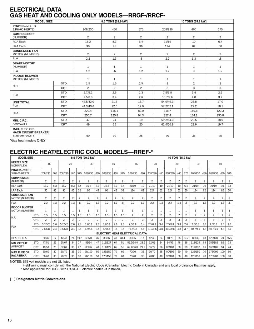
ELECTRICAL DATAGAS HEAT AND COOLING ONLY MODELS—RRGF-/RRCF-
MODEL SIZE 8.5 TONS [29.9 kW] 10 TONS [35.2 kW]
POWER—VOLTS3 PH-60 HERTZ 208/230 460 575 208/230 460 575
COMPRESSOR(NUMBER) 2 2 2 2 2 2
RLA Each 16.2 8.3 6.4 21/19 10 6.4
LRA Each 90 45 36 124 62 50
CONDENSER FANMOTOR (NUMBER) 2 2 2 2 2 2
2.2 1.3 .8 2.2 1.3 .8
DRAFT MOTOR*(NUMBER) 1 1 1 1 1 1
FLA 1.2 .6 1.2 1.2 .6 1.2
INDOOR BLOWERMOTOR (NUMBER) 1 1 1 1 1 1
H.P.1.5 1.5 1.5 2 2 2
2 2 2 3 3 3
FLA5.7/5.2 2.6 2.3 7.5/6.8 3.4 2.6
7.5/6.8 3.4 2.6 10.7/9.6 4.8 3.7
UNIT TOTALFLA
42.5/42.0 21.8 16.7 54.0/49.3 25.8 17.0
44.3/43.6 22.6 17.0 57.2/52.1 27.2 18.1
LRA229.4 115.1 89.0 318.7 159.8 122.3
250.7 125.8 94.3 327.4 164.1 130.8
MIN. CIRC.AMPACITY
47 24 19 59.2/54.0 28.5 18.6
49 25 20 62.4/56.8 29.9 19.7
MAX. FUSE ORHACR CIRCUIT BREAKERSIZE-AMPACITY 60 30 25 70 35 25
STD.
STD.
STD.
STD.
STD.
OPT.
OPT.
OPT.
OPT.
OPT.
FLA
*Gas heat models ONLY
ELECTRIC HEAT/ELECTRIC COOL MODELS—RREF-*MODEL SIZE 8.5 TON [29.9 kW] 10 TON [35.2 kW]
RLA Each 16.2 8.3 16.2 8.3 6.4 16.2 8.3 16.2 8.3 6.4 21/19 10 21/19 10 21/19 10 6.4 21/19 10 21/19 10 6.4
LRA Each 90 45 90 45 36 90 45 90 45 36 124 62 124 62 124 62 50 124 62 124 62 50
CONDENSER FANMOTOR (NUMBER) 2 2 2 2 2 2 2 2 2 2 2 2 2 2 2 2 2 2 2 2 2 2
FLA 2.2 1.3 2.2 1.3 .8 2.2 1.3 2.2 1.3 .8 2.2 1.3 2.2 1.3 2.2 1.3 .8 2.2 1.3 2.2 1.3 .8
INDOOR BLOWERMOTOR (NUMBER) 1 1 1 1 1 1 1 1 1 1 1 1 1 1 1 1 1 1 1 1 1 1
H.P.1.5 1.5 1.5 1.5 1.5 1.5 1.5 1.5 1.5 1.5 2 2 2 2 2 2 2 2 2 2 2 2
2 2 2 2 2 2 2 2 2 2 3 3 3 3 3 3 3 3 3 3 3 3
FLA5.7/5.2 2.6 5.7/5.2 2.6 2.3 5.7/5.2 2.6 5.7/5.2 2.6 2.3 7.5/6.8 3.4 7.5/6.8 3.4 7.5/6.8 3.4 2.6 7.5/6.8 3.4 7.5/6.8 3.4 2.6
7.5/6.8 3.4 7.5/6.8 3.4 2.6 7.5/6.8 3.4 7.5/6.8 3.4 2.6 10.7/9.6 4.8 10.7/9.6 4.8 10.7/9.6 4.8 3.7 10.7/9.6 4.8 10.7/9.6 4.8 3.7
ELECTRIC HEAT ELECTRICAL DATA
HEATER FLA 30/35 17 42/48 24 19.2 60/70 35 83/96 48 38.4 30/35 17 42/48 24 60/70 35 27.7 83/96 48 120/139 70 55.5
MIN. CIRCUITAMPACITY
47/51 25 60/67 34 27 83/94 47 111/127 64 51 59.2/54.0 28.5 62/69 34 84/96 48 38 113/129 64 159/182 92 73
49/53 26 62/69 35 27 85/96 48 114/129 65 51 62.4/56.8 29.9 66/72 36 88/100 50 39 117/132 66 163/186 94 74
MAX. FUSE ORHACR BRKR.
60/60 30 60/70 35 30 90/100 50 125/150 70 60 70/70 35 70/70 35 90/100 50 40 125/150 70 175/200 100 80
60/60 30 70/70 35 30 90/100 50 125/150 70 60 70/70 35 70/80 40 90/100 50 40 125/150 70 175/200 100 80
POWER—VOLTS3 PH-60 HERTZ 208/230 460 208/230 460 575 208/230 460 208/230 460 575 208/230 460 208/230 460 208/230 460 575 208/230 460 208/230 460 575
COMPRESSOR(NUMBER) 2 2 2 2 2 2 2 2 2 2 2 2 2 2 2 2 2 2 2 2 2 2
STD.
OPT.
STD.
OPT.
STD.
OPT.
STD.
OPT.
HEATER SIZENOMINAL kW 15 20 30 40 15 20 30 40 60
NOTES: 575 volt models are not UL listed.Field wiring must comply with the National Electric Code (Canadian Electric Code in Canada) and any local ordinance that may apply.
*Also applicable for RRCF with RXSE-BF electric heater kit installed.
[ ] Designates Metric Conversions
17
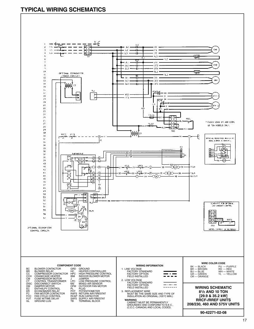
TYPICAL WIRING SCHEMATICS
COMPONENT CODEBC BLOWER CONTACTOR GRD GROUNDBR BLOWER RELAY HC HEATER CONTROLLERCC COMPRESSOR CONTACTOR HPC HIGH PRESSURE CONTROLCCH CRANKCASE HEATER IBM INDOOR BLOWER MOTORCM COMPRESSOR MOTOR J JUMPERCT CONTROL TRANSFORMER LPC LOW PRESSURE CONTROLDISC DISCONNECT SWITCH MS MIXED AIR SENSORDM DAMPER MOTOR OFM OUTDOOR FAN MOTOREC ENTHALPY CONTROL PL PLUGER ECONOMIZER RELAY POT POTENTIOMETERFC FAN MOTOR CONTACTOR RAFS RETURN AIR FIRESTATFCC FAN CYCLE CONTROL RCAP RUN CAPACITORFUT FUSE W/TIME DELAY SAFS SUPPLY AIR FIRESTATGL GROUND LUG TB TERMINAL BLOCK
WIRING INFORMATION1. LINE VOLTAGE
FACTORY STANDARDFACTORY OPTIONFIELD INSTALLED
2. LOW VOLTAGEFACTORY STANDARDFACTORY OPTIONFIELD INSTALLED
3. REPLACEMENT WIREMUST BE THE SAME SIZE AND TYPE OFINSULATION AS ORIGINAL (105°C MIN.)
WARNINGCABINET MUST BE PERMANENTLY GROUNDED AND CONFORM TO N.E.C.,(C.E.C.-CANADA) AND LOCAL CODES.
90-42271-02-08
WIRING SCHEMATIC81/2 AND 10 TON[29.9 & 35.2 kW]
RRCF-/RREF UNITS208/230, 460 AND 575V UNITS
WIRE COLOR CODEBK — BLACK PU — PURPLEBR — BROWN RD — REDBU — BLUE WH — WHITEGR — GREEN YL — YELLOWOR — ORANGE
18
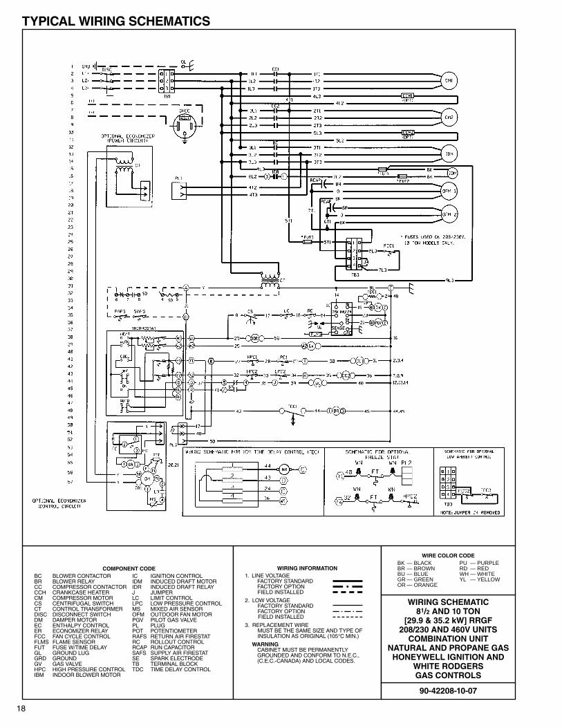
TYPICAL WIRING SCHEMATICS
COMPONENT CODEBC BLOWER CONTACTOR IC IGNITION CONTROLBR BLOWER RELAY IDM INDUCED DRAFT MOTORCC COMPRESSOR CONTACTOR IDR INDUCED DRAFT RELAYCCH CRANKCASE HEATER J JUMPERCM COMPRESSOR MOTOR LC LIMIT CONTROLCS CENTRIFUGAL SWITCH LPC LOW PRESSURE CONTROLCT CONTROL TRANSFORMER MS MIXED AIR SENSORDISC DISCONNECT SWITCH OFM OUTDOOR FAN MOTORDM DAMPER MOTOR PGV PILOT GAS VALVEEC ENTHALPY CONTROL PL PLUGER ECONOMIZER RELAY POT POTENTIOMETERFCC FAN CYCLE CONTROL RAFS RETURN AIR FIRESTATFLMS FLAME SENSOR RC ROLLOUT CONTROLFUT FUSE W/TIME DELAY RCAP RUN CAPACITORGL GROUND LUG SAFS SUPPLY AIR FIRESTATGRD GROUND SE SPARK ELECTRODEGV GAS VALVE TB TERMINAL BLOCKHPC HIGH PRESSURE CONTROL TDC TIME DELAY CONTROLIBM INDOOR BLOWER MOTOR
WIRING INFORMATION1. LINE VOLTAGE
FACTORY STANDARDFACTORY OPTIONFIELD INSTALLED
2. LOW VOLTAGEFACTORY STANDARDFACTORY OPTIONFIELD INSTALLED
3. REPLACEMENT WIREMUST BE THE SAME SIZE AND TYPE OFINSULATION AS ORIGINAL (105°C MIN.)
WARNINGCABINET MUST BE PERMANENTLY GROUNDED AND CONFORM TO N.E.C.,(C.E.C.-CANADA) AND LOCAL CODES.
90-42208-10-07
WIRING SCHEMATIC81/2 AND 10 TON
[29.9 & 35.2 kW] RRGF208/230 AND 460V UNITS
COMBINATION UNITNATURAL AND PROPANE GAS
HONEYWELL IGNITION ANDWHITE RODGERS GAS CONTROLS
WIRE COLOR CODEBK — BLACK PU — PURPLEBR — BROWN RD — REDBU — BLUE WH — WHITEGR — GREEN YL — YELLOWOR — ORANGE
19
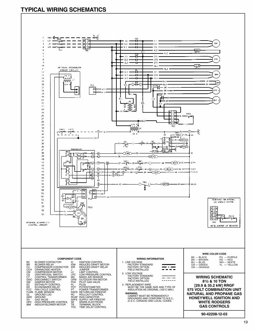
TYPICAL WIRING SCHEMATICS
COMPONENT CODEBC BLOWER CONTACTOR IC IGNITION CONTROLBR BLOWER RELAY IDM INDUCED DRAFT MOTORCC COMPRESSOR CONTACTOR IDR INDUCED DRAFT RELAYCCH CRANKCASE HEATER J JUMPERCM COMPRESSOR MOTOR LC LIMIT CONTROLCS CENTRIFUGAL SWITCH LPC LOW PRESSURE CONTROLCT CONTROL TRANSFORMER MS MIXED AIR SENSORDISC DISCONNECT SWITCH OFM OUTDOOR FAN MOTORDM DAMPER MOTOR PGV PILOT GAS VALVEEC ENTHALPY CONTROL PL PLUGER ECONOMIZER RELAY POT POTENTIOMETERFCC FAN CYCLE CONTROL PT POWER TRANSFORMERFLMS FLAME SENSOR RAFS RETURN AIR FIRESTATGL GROUND LUG RC ROLLOUT CONTROLGRD GROUND RCAP RUN CAPACITORGV GAS VALVE SAFS SUPPLY AIR FIRESTATHPC HIGH PRESSURE CONTROL SE SPARK ELECTRODEIBM INDOOR BLOWER MOTOR TB TERMINAL BLOCK
TDC TIME DELAY CONTROL
WIRING INFORMATION1. LINE VOLTAGE
FACTORY STANDARDFACTORY OPTIONFIELD INSTALLED
2. LOW VOLTAGEFACTORY STANDARDFACTORY OPTIONFIELD INSTALLED
3. REPLACEMENT WIREMUST BE THE SAME SIZE AND TYPE OFINSULATION AS ORIGINAL (105°C MIN.)
WARNINGCABINET MUST BE PERMANENTLY GROUNDED AND CONFORM TO N.E.C.,(C.E.C.-CANADA) AND LOCAL CODES.
90-42208-12-03
WIRING SCHEMATIC81/2 & 10 TON
[29.9 & 35.2 kW] RRGF575 VOLT COMBINATION UNITNATURAL AND PROPANE GAS
HONEYWELL IGNITION ANDWHITE RODGERS GAS CONTROLS
WIRE COLOR CODEBK — BLACK PU — PURPLEBR — BROWN RD — REDBU — BLUE WH — WHITEGR — GREEN YL — YELLOWOR — ORANGE
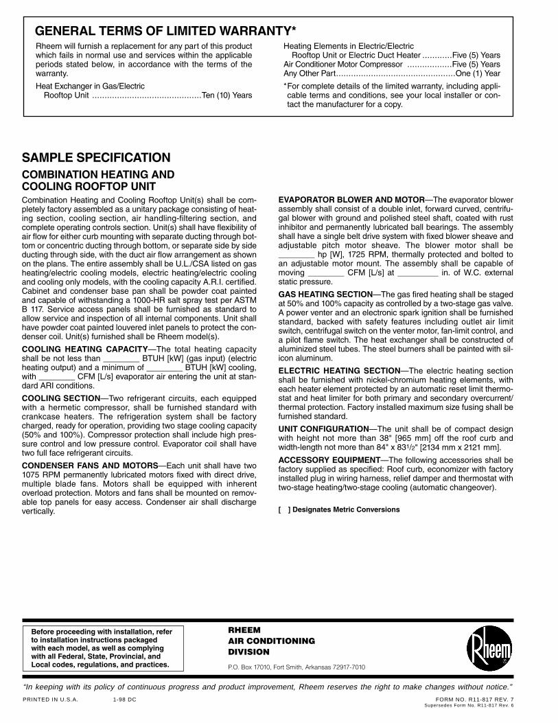
GENERAL TERMS OF LIMITED WARRANTY*Rheem will furnish a replacement for any part of this productwhich fails in normal use and services within the applicableperiods stated below, in accordance with the terms of thewarranty.
Heat Exchanger in Gas/ElectricRooftop Unit ............................................Ten (10) Years
Heating Elements in Electric/ElectricRooftop Unit or Electric Duct Heater ............Five (5) Years
Air Conditioner Motor Compressor ..................Five (5) YearsAny Other Part................................................One (1) Year
*For complete details of the limited warranty, including appli-cable terms and conditions, see your local installer or con-tact the manufacturer for a copy.
SAMPLE SPECIFICATIONCOMBINATION HEATING ANDCOOLING ROOFTOP UNITCombination Heating and Cooling Rooftop Unit(s) shall be com-pletely factory assembled as a unitary package consisting of heat-ing section, cooling section, air handling-filtering section, andcomplete operating controls section. Unit(s) shall have flexibility ofair flow for either curb mounting with separate ducting through bot-tom or concentric ducting through bottom, or separate side by sideducting through side, with the duct air flow arrangement as shownon the plans. The entire assembly shall be U.L./CSA listed on gasheating/electric cooling models, electric heating/electric coolingand cooling only models, with the cooling capacity A.R.I. certified.Cabinet and condenser base pan shall be powder coat paintedand capable of withstanding a 1000-HR salt spray test per ASTMB 117. Service access panels shall be furnished as standard toallow service and inspection of all internal components. Unit shallhave powder coat painted louvered inlet panels to protect the con-denser coil. Unit(s) furnished shall be Rheem model(s).
COOLING HEATING CAPACITY—The total heating capacityshall be not less than ________ BTUH [kW] (gas input) (electricheating output) and a minimum of ________ BTUH [kW] cooling,with ________ CFM [L/s] evaporator air entering the unit at stan-dard ARI conditions.
COOLING SECTION—Two refrigerant circuits, each equippedwith a hermetic compressor, shall be furnished standard withcrankcase heaters. The refrigeration system shall be factorycharged, ready for operation, providing two stage cooling capacity(50% and 100%). Compressor protection shall include high pres-sure control and low pressure control. Evaporator coil shall havetwo full face refrigerant circuits.
CONDENSER FANS AND MOTORS—Each unit shall have two1075 RPM permanently lubricated motors fixed with direct drive,multiple blade fans. Motors shall be equipped with inherentoverload protection. Motors and fans shall be mounted on remov-able top panels for easy access. Condenser air shall dischargevertically.
EVAPORATOR BLOWER AND MOTOR—The evaporator blowerassembly shall consist of a double inlet, forward curved, centrifu-gal blower with ground and polished steel shaft, coated with rustinhibitor and permanently lubricated ball bearings. The assemblyshall have a single belt drive system with fixed blower sheave andadjustable pitch motor sheave. The blower motor shall be________ hp [W], 1725 RPM, thermally protected and bolted to an adjustable motor mount. The assembly shall be capable ofmoving ________ CFM [L/s] at _________ in. of W.C. externalstatic pressure.
GAS HEATING SECTION—The gas fired heating shall be stagedat 50% and 100% capacity as controlled by a two-stage gas valve.A power venter and an electronic spark ignition shall be furnishedstandard, backed with safety features including outlet air limitswitch, centrifugal switch on the venter motor, fan-limit control, anda pilot flame switch. The heat exchanger shall be constructed ofaluminized steel tubes. The steel burners shall be painted with sil-icon aluminum.
ELECTRIC HEATING SECTION—The electric heating sectionshall be furnished with nickel-chromium heating elements, witheach heater element protected by an automatic reset limit thermo-stat and heat limiter for both primary and secondary overcurrent/thermal protection. Factory installed maximum size fusing shall befurnished standard.
UNIT CONFIGURATION—The unit shall be of compact designwith height not more than 38" [965 mm] off the roof curb andwidth-length not more than 84" x 831/2" [2134 mm x 2121 mm].
ACCESSORY EQUIPMENT—The following accessories shall befactory supplied as specified: Roof curb, economizer with factoryinstalled plug in wiring harness, relief damper and thermostat withtwo-stage heating/two-stage cooling (automatic changeover).
[ ] Designates Metric Conversions
Before proceeding with installation, referto installation instructions packagedwith each model, as well as complyingwith all Federal, State, Provincial, andLocal codes, regulations, and practices.
RHEEMAIR CONDITIONINGDIVISION
P.O. Box 17010, Fort Smith, Arkansas 72917-7010
“In keeping with its policy of continuous progress and product improvement, Rheem reserves the right to make changes without notice.”
PRINTED IN U.S.A. 1-98 DC FORM NO. R11-817 REV. 7Supersedes Form No. R11-817 Rev. 6