Embed Size (px)
Citation preview
Commercial - Light Industrial PrecinctSTRUCTURE PLAN
August 201206406P
Commercial - Light Industrial PrecinctSTRUCTURE PLAN
i
CONTENTS1.0 Introduction ........................................................................................................................... 1
1.1 Background ................................................................................................................ 12.0 Physical Context ................................................................................................................... 2
2.1 Site and Situation ....................................................................................................... 22.2 Land Tenure ................................................................................................................ 22.3 Landform .................................................................................................................... 2
3.0 Statutory Context ................................................................................................................. 43.1 Statement of Planning Policy No. 1 ......................................................................... 43.2 State Planning Strategy............................................................................................. 43.3 Greater Bunbury Region Scheme ............................................................................ 53.4 Bunbury Wellington Region Plan and Greater Bunbury Structure Plan .................. 53.5 Shire of Harvey District Town Planning Scheme No.1(TPS No.1) ........................... 53.7 Treendale District Centre Structure Plan ................................................................. 9
4.0 Concept Development ..................................................................................................... 124.1 Design Philosophy ................................................................................................... 124.2 Relationship to District Centre ................................................................................ 124.3 Interface with Australind Bypass ............................................................................ 124.4 Interface with Residential Landuses ...................................................................... 144.5 Servicing .................................................................................................................... 14
4.5.1 Roads ........................................................................................................ 144.5.2 Drainage ................................................................................................... 144.5.3 Sewerage ................................................................................................. 154.5.4 Water Supply ............................................................................................ 154.5.5 Power ........................................................................................................ 154.5.6 Telecommunications ............................................................................... 154.5.7 Gas ............................................................................................................ 15
4.6 Design Guidelines .................................................................................................... 155.0 Implementation .................................................................................................................. 16
5.1 Structure Plan Approval .......................................................................................... 164.6 Design Guidelines .................................................................................................... 224.7 Application of Guidelines ....................................................................................... 224.8 Design Guideline Elements ..................................................................................... 22
Commercial - Light Industrial PrecinctSTRUCTURE PLAN
ii
L IST OF FIGURESFigure 1 Location Plan .............................................................................................................. 3Figure 2 Extract from Greater Bunbury Region Scheme ...................................................... 6Figure 3 Greater Bunbury Structure Plan ................................................................................ 7Figure 4 Existing Zoning ............................................................................................................. 8Figure 5 Treendale Farm Structure Plan ................................................................................ 10Figure 6 District Centre Structure Plan .................................................................................. 11Figure 7 Subdivision Concept Plan ....................................................................................... 13Figure 8 Typical Cross Section ............................................................................................... 14Figure 9 Structure Plan Policy Statements ............................................................................ 21Figure 10 Precinct Plans and Statements ............................................................................... 22
L IST OF APPENDICESAppendix A Certifi cates of TitleAppendix B Zoning Table ExtractsAppendix C Design Guidelines
Commercial - Light Industrial PrecinctSTRUCTURE PLAN
1
1.0 Introduction
1.1 Background
The Shire of Harvey is experiencing an extended period of signifi cant economic and urban growth in the Australind Urban Corridor. It is timely that provision be made for an adequate level of services to support this growth.
Approval of this structure plan by both Council and the Western Australian Planning Commission (WAPC) will establish the framework for future rezoning, subdivision and development.
Commercial - Light Industrial PrecinctSTRUCTURE PLAN
2
2.0 Phys ical Context
2.1 Site and Situation
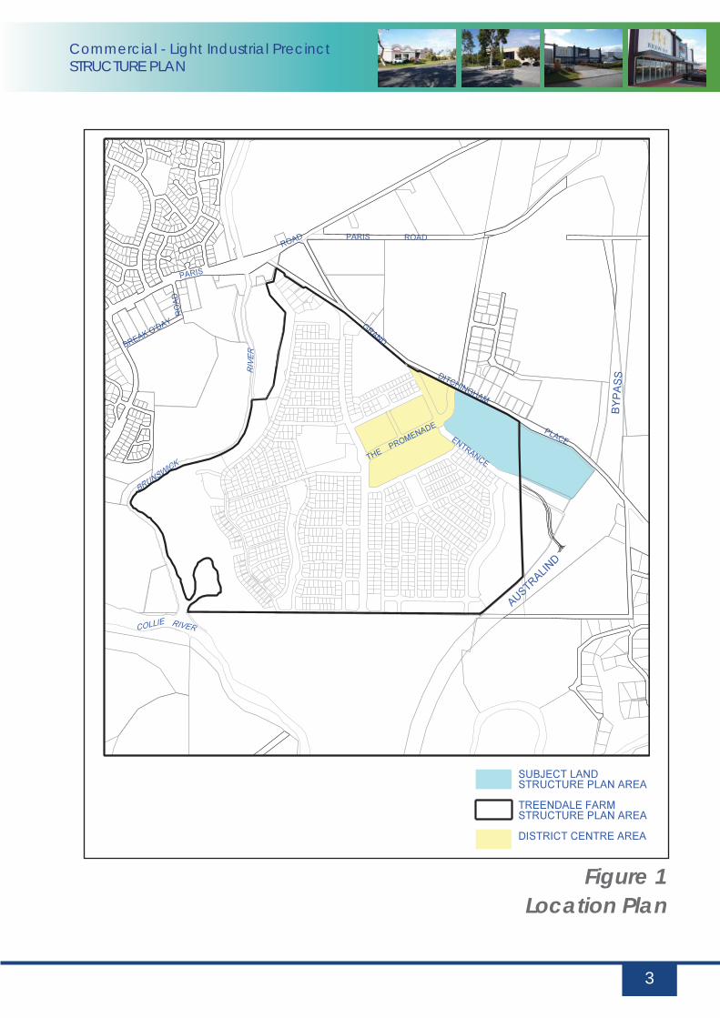
The subject land is situated in the Eaton/Australind Urban Growth Corridor extending northward from the City of Bunbury (see Figure 1 – Location Plan).
The subject land is located within urban expansion areas of Treendale and Kingston and will eventually link south across the Collie River to Millbridge, the Peninsula and Eaton.
2.2 Land Tenure
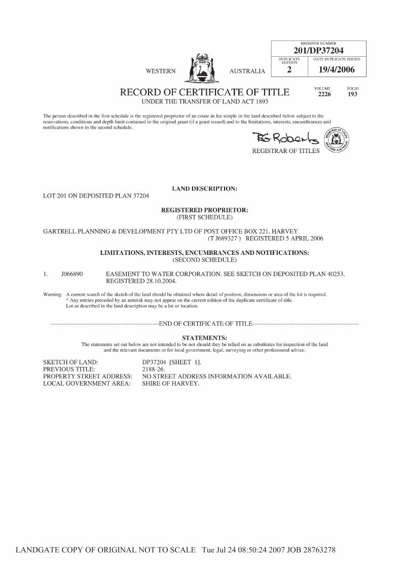
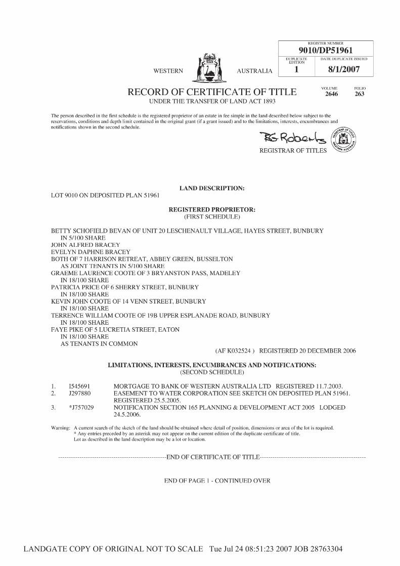
The subject land is located of two titles in separate ownership. The land is described as Lots 201 on deposited plan 37204 and Lot 9010 on deposited plan 51961 (see Appendix A – Certifi cate of Titles).
2.3 Landform
The proposed “Commercial Light Industrial Precinct” site is situated on a cleared area. The site is extremely fl at with a uniformed elevation of 13.8 metres AHD.
Geotechnical investigations have indicated that there are no acid sulphate soils in the area and that the land form does not impose signifi cant servicing constraints.
Commercial - Light Industrial PrecinctSTRUCTURE PLAN
3
Figure 1Location Plan
Commercial - Light Industrial PrecinctSTRUCTURE PLAN
4
3.0 Statutory Context
3.1 Statement of Planning Policy No. 1
The Statement of Planning Policy No. 1 is the State planning framework. It incorporates the State Planning Strategy and existing regional policies and plans into an ordered hierarchy for decision making on land use and development. As a Statement of Planning Policy, the Commission and Local Governments’ must have “due regard” to the provisions when making decisions on planning matters.
3.2 State Planning Strategy
The State Planning Strategy was adopted by the Western Australian Planning Commission in December 1997. It is designed to provide a strategic guide for land use planning throughout the State through to the year 2029. The strategy sets out:
• A common vision for development in the State and for the regions within it.• Provides a guide to the State Government on its land use planning response and on the
programs and actions required to achieve the visions set out in the strategy.• Identifi es the likely changes and prepares for them.• Establishes the mechanisms to ensure the strategy is implemented and kept current.
The State Planning Strategy’s vision is to:“…signifi cantly contribute to the quality of life of all Western Australians in the years to 2029, by using the landuse planning system to facilitate and contribute to regional wealth; the preservation and enhancement of the environment; and the building of dynamic and safe communities which nurture human activity.” (Page 2)
The Strategy recognises that the South West Urban System (extending from Perth, south to Bunbury, Busselton and Albany) will be subject to substantial development pressure. It requires the area to be managed by developing more sustainable and identifi able new communities, protection of natural resource areas and reinforcement of strategic transport routes.
Commercial - Light Industrial PrecinctSTRUCTURE PLAN
5
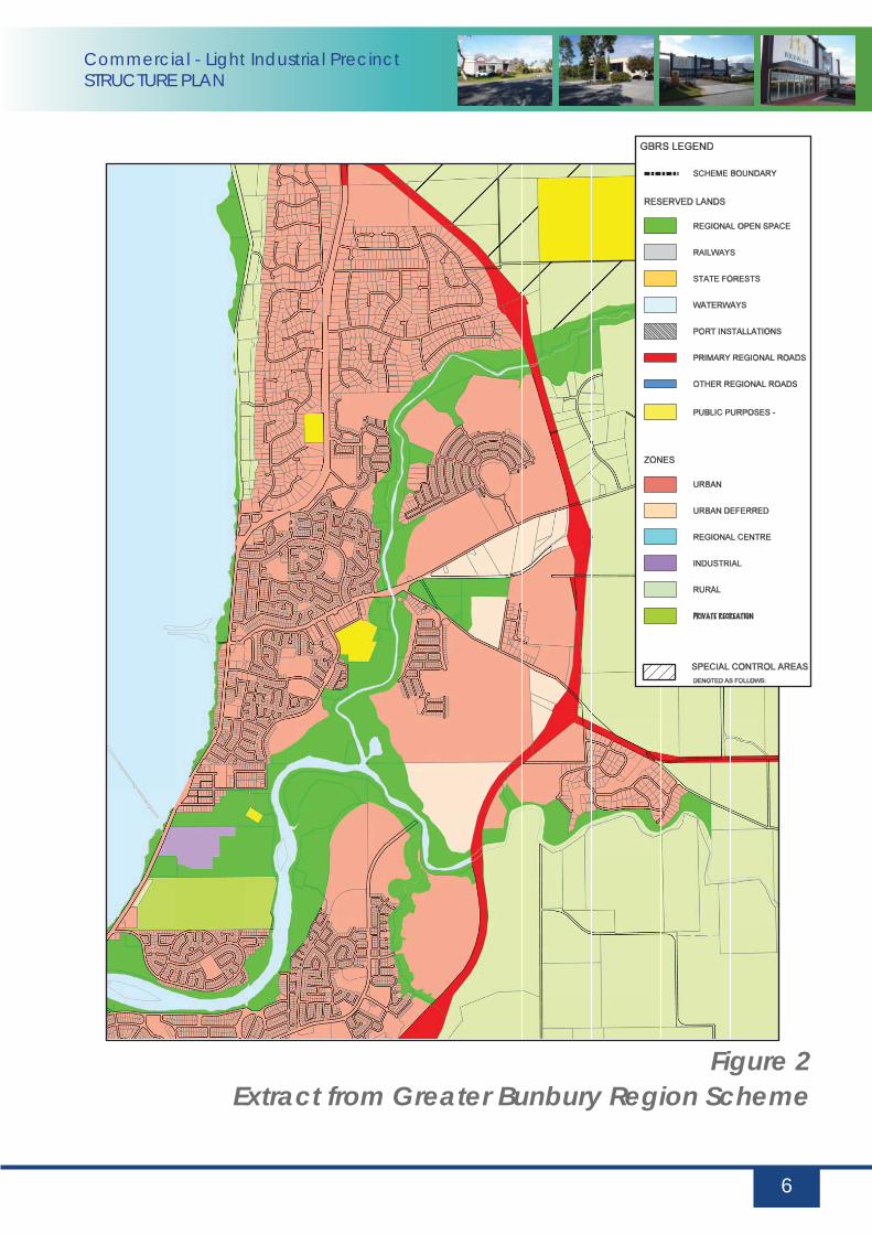
3.3 Greater Bunbury Region Scheme
The Greater Bunbury Region Scheme provides regional level statutory controls for the Greater Bunbury Area.
Figure 2 - Greater Bunbury Region Scheme identifi es the western portion of the subject land as “Urban” and the balance as “Urban Deferred”. This land use designation incorporates “… areas in which a range of activities, including residential, commercial, recreational and light industrial are undertaken.”
3.4 Bunbury Wellington Region Plan and Greater Bunbury Structure Plan
The Bunbury – Wellington Region Plan and Greater Bunbury Structure Plan were endorsed by State Cabinet in 1995. They provide a framework in which Local Government Town Planning Schemes have been evaluated. Figure 3 - Greater Bunbury Structure Plan identifi es the subject land in its wider context.
The Greater Bunbury Structure Plan includes the subject land within planning unit CO6 which is identifi ed for “… medium – long term urban expansion, with a District Commercial Centre, Light Industrial Area and wide reserves along the river”. Planning guidelines also recommend a requirement for the Structure Plan.
The unit statement also includes a limitation on the size of the proposed District Centre to neighbourhood size until at least the year 2006, but encouraged the early establishment of local shopping and district level business and community service functions. In addition, it promotes “local shopping and district level business, community service functions” as well as “local commercial and civic facilities” within the District Centre Precinct.
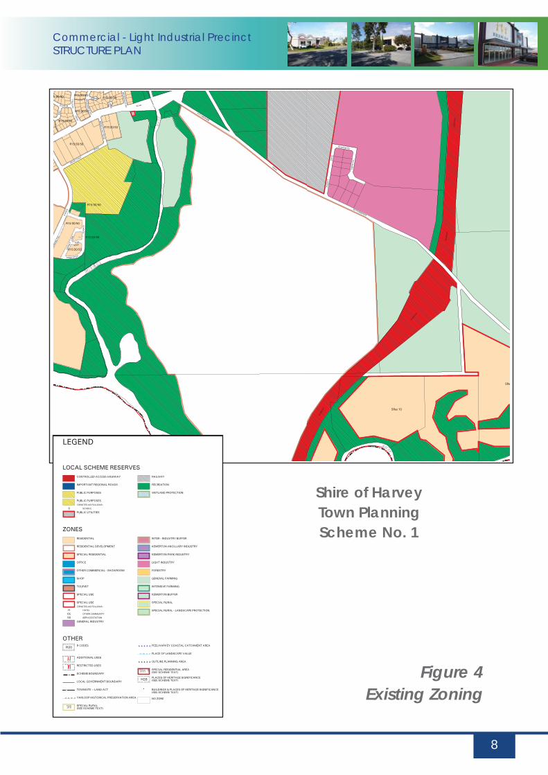
3.5 Shire of Harvey District Town Planning Scheme No.1(TPS No.1)
The Shire of Harvey Town Planning Scheme No.1 was gazetted on the 12th of November 1996. The majority of the subject land and surrounding Treendale neighbourhood is zoned “Residential Development” (see Figure 4 – Existing Zoning). The eastern portion is zoned “General Farming”. The southern portion of “General Farming” zoned land is presently the subject of Town Planning Scheme Amendment No.70. This amendment is waiting gazettal. The land subject to this structure plan will be subject to a seperate amendment proposal.
Commercial - Light Industrial PrecinctSTRUCTURE PLAN
6
Figure 2Extract from Greater Bunbury Region Scheme

Commercial - Light Industrial PrecinctSTRUCTURE PLAN
7
Figure 3Greater Bunbury Structure Plan
Parks, Recreation And DrainageAreas Under Consideration For ConservationScenic Protection And Reservation
Rural ResidentialSpecial Amenity AreaExisting UrbanFuture Urban (Category A)Future Urban (Category B)Regional CentreCentral Business DistrictDistrict Centre
Mixed Use Buffer
Mixed Business AreaHarbour And Port Related Industries
Tourism And Recreation Development
IndustrialRural
Major Service CorridorPublic Purposes (Denoted As Follows) :
High SchoolPost-Secondary EducationPrisonHospital
LEGEND
BUFFER AREA SUBJECTTO DETAILED STUDYBY WATER AUTHORITY
SUBJECT TO CURRENTENVIRONMENTALASSESSMENT
SUBJECT TO DECOMMISSIONINGOF WASTE WATER TREATMENTWORKS (See Report)
SUBJECT TO DECOMMISSIONINGOF WASTE WATER TREATMENTWORKS (See Report)
Major Surface Water Catchment Boundary
Local Government Boundary
Waste Water Treatment WorksAnd Indicative Buffer
CemeteryRegional Recreation Centre
Primary Distributor Major River
Railway
District Distributor (Arterial)
Port
TO BE DETERMINED BYSPECIAL STUDY
FINAL ALIGNMENT OFSOUTH WESTERN HIGHWAY
Aerodrome
Special Development AreaConservation/Landscape Value
SUBJECT TO FUTUREENVIRONMENTALASSESSMENT ANDKEMERTON PORTINVESTIGATIONS
FINAL ROAD ALIGNMENT SUBJECT TODETAILED STUDY BY MAIN ROADS W.A.
"ZONINGS" AND LAYOUT WITHIN PICTONAND PRESTON AREAS MAY VARY AFTERFURTHER STUDY OF THE SCOPE OFFUTURE INDUSTRY
District Distributor (Subarterial)
0
metres
2500 5000
Bunbury-WellingtonRegion Plan
GREATER BUNBURYSTRUCTURE PLAN
2500
Ministry for PlanningWESTERN AUSTRALIA
Figure 16
OCTOBER 1995
WELLESLEY
ROAD
TREASURE
ROAD
MARRIOTT ROAD
WE
LLES
LEY
OLD
CO
AS
TR
OA
D
ROAD
SOUTH
WESTERN
KOOMBANA
DR
BL
AI R
ST
ESTUARY
DR
OCEA
NDR
IVE
BU
SS
EL
L
HIG
HW
AY
BU
SS
ELL
HIG
HWA
Y
TheMaidens
RAYMOND
ROAD
PARIS
RO
AD
OLD
CO
AS
T
Regional Refuse
Disposal Site
ROAD
HIGHWAY
DAR
DAN
UP
RO
AD
SOUTH
WE
STE
RN
HIG
HW
AY
NORTH
BO
YA
NU
PR
OA
D
ROADCENTENARY
HAREWOODROAD
EATON
PRESTON
STRATHAM
AUSTRALIND
KEMERTON
MYALUP
BINNINGUP
LESCHENAULT
ESTUARY
WaterlooHead
SamphireBay
PelicanPointTurkey
Point
VittoriaBay
KOOMBANABAY
MinninupBeach
DalyellupBeach
H AR VE Y R IVE
R
D I V ER S I ON D R A I N
WE
LL
ES
LEY
RI V
ER
B RU NS W I C K
RIV
ER
R IV ERCOL L
IE
C O L LI E
PR
E ST O
RIV
ER
N
F i v e M i l e B r o ok
Dr a
i n
LakeBeridup
CokelupSwamp
RushSwamp
BigSwamp
MuddyLake
PointCasuarina
R I V E R
HARBOUROUTER
GLEN IRIS
HARBOURINNER
GELORUP
SHIRE
OF
HARVEY
SHIRE
OF
DARDANUP
SHIRE
OF
CAPEL
CITY
OF
BUNBURY
H.S.P.S.E.P.H.
H.S.
H.S.
H.S.
H.P.S.E.
H.S.P.
H.S. H.S.
H.S.
C.R.
C.
C.
R.
A.
A.
H.S.
H.S.
H.S.
Commercial - Light Industrial PrecinctSTRUCTURE PLAN
8
Figure 4 Existing Zoning
Shire of HarveyTown Planning Scheme No. 1

Commercial - Light Industrial PrecinctSTRUCTURE PLAN
9
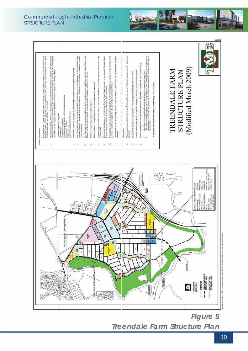
3.6 Treendale Structure Plan
The Treendale Farm Structure Plan dated April 2001 has been endorsed by the Shire of Harvey and the Western Australian Planning Commission (see Figure 5 – Treendale Farm Structure Plan).
Subsequent to the adoption of this document, minor modifi cations to the Structure Plan have been ongoing. These do not signifi cantly impact on this site. Figure 5 depicts the current structure plan.
The philosophy of the Treendale Farm Structure Plan encompasses the following objectives:• To protect the environmental qualities of the Collie and Brunswick Rivers associated
wetlands and fl ood plains;• To build upon the local and regional planning for the area and create a vibrant district
centre that will act as a cultural and commercial focus for the locality;• To be innovative in the application of urban design principles and incorporate key
aspects of the Liveable Neighbourhoods Community Design Code;• To provide a mechanism which will allow refi nement and staging of the Treendale Farm
Structure Plan;• To provide for strong pedestrian connectivity utilizing a permeable road network, open
space linkages and conservation areas;• To develop an integrated open space and drainage network which maximizes ground
water recharge at source and ensure urban runoff is stripped of nutrients prior to discharging; and
• Given the fl at topography of the site, artifi cial focuses, or landmarks, are to be created by strategic use of open space and concentrating more intensive land uses at specifi c points and emphasizing these locations by adopting regid geometric road layouts.
The Structure Plan has been developed to promote a broad range of employment generated land uses to foster a vibrant and self sustaining community including district and local commercial centres, industrial, service commercial and mixed business areas.
3.7 Treendale District Centre Structure Plan
The subject land abuts the proposed Treendale District Centre site (see Figure 6 – Treendale District Centre Structure Plan). This structure plan has been adopted by the Shire of Harvey and the Western Australian Planning Commission. It provides for detailed consideration of:
• fl oor space; • streetscape;• building design principles; • built form; and• servicing.
Commercial - Light Industrial PrecinctSTRUCTURE PLAN
10
Figure 5Treendale Farm Structure Plan

Commercial - Light Industrial PrecinctSTRUCTURE PLAN
11
ENC
LOSE
D P
EDES
TRIA
N E
NV
IRO
NM
ENT
(to
rem
ain
open
dur
ing
stan
dar
d c
entre
ope
ratin
g ho
urs)
USES
IN T
HIS
LOC
ATIO
N S
HOUL
D A
TTEM
PT T
O A
CTIV
ATE
AFT
ER H
OUR
S A
CTIV
ITY
LAN
DM
ARK
BUI
LDIN
G S
ITE
R C
OD
E D
ENSI
TY
BUS
STO
P
INTE
GRA
TOR
B
INTE
GRA
TOR
B - T
OW
N C
ENTR
E M
AIN
STR
EET
** *
*
*Subj
ect t
o se
para
test
ruct
ure
plan
ning
R80
R80
R80
R80
R80
R80
R80
R80
R80 R8
0
R80
R80
RESI
DEN
TIAL
RETA
IL
OFF
ICE
MED
ICA
L
MIX
ED U
SE
FOO
D &
EN
TERT
AIN
MEN
T
CO
MM
UNITY
USE
/ R
ESER
VE
SHO
WRO
OM
S N
URSE
RY
OFF
ICE
RESI
DEN
TIAL
OFF
ICE
POS
RESE
RVE
Figure 6District Centre Structure Plan

Commercial - Light Industrial PrecinctSTRUCTURE PLAN
12
4.0 Concept Development
4.1 Design Philosophy
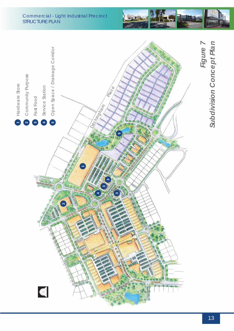
The design philosophy of the “Commercial – Light Industrial Precinct Concept Structure Plan” is to provide a high level of local amenity and provide a clear demarcation between private and public land. (See Figure 7 – Concept Plan). The proposed layout ensures that no lots back directly onto the landscaped highway buffers.
The proposed public open space corridor provides high levels of accessibility through the subject land to future “Community Purpose” sites and provides a safe linkage to the adjoining District Centre site.
The proposal depicts a range of lot sizes to ensure that a wide range of activities can be accommodated on the subject land.
4.2 Relationship to District Centre
The concept plan depicts a complementary and integrated transition of land uses between “District Centre” uses on the western boundary and “Light Industrial” land to the north. The concept plan shows a hardware store to mediate uses and defi ne the north western interface edge with existing light industrial uses. The western edge provides opportunity for built form to address the street and provide an attractive interface with the adjoining community purpose site and screen car parking from the street environment.
The south western section includes a potential fast food precinct that will interface with the proposed fast food site within the district centre. I high degree of streetscape amenity can be achieved through the limited use of crossovers and orientation of buildings to address the public realm. The balance of the site serviced by internal roads to additional setbacks and landscaping treatments to ensure an attractive interface with abutting future residential land use to the south.
4.3 Interface with Australind Bypass
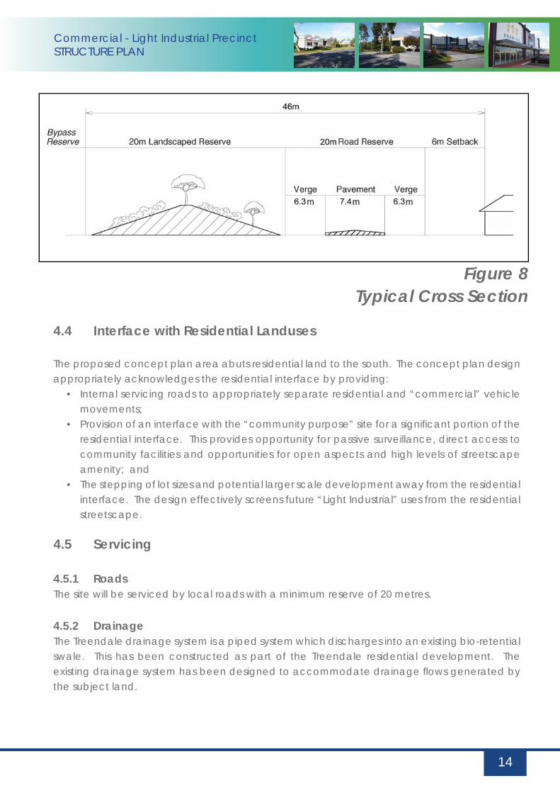
The proposed concept plan is consistent with the intent of the Treendale Farm Structure Plan which identifi es a “POS and Landscape Buffer” along the Australind Bypass interface. The proposed concept plan depicts a 20m POS strip abutting the Bypass reserve which is intended to contain a landscaped bund (see Figure 8 – Typical Cross Section). This “buffer” is further expanded by the use of a 20m wide internal servicing road, which maximizes the opportunity for buffering and screening development from the Bypass, while providing scope for passive surveillance.
Commercial - Light Industrial PrecinctSTRUCTURE PLAN
13
Figu
re 7
Subd
ivisi
on C
once
pt P
lan
Ditc
hing
ham
Pla
ce
Hard
war
e St
ore
Com
mun
ity P
urpo
se
Fast
Foo
d
Serv
ice
Stat
ion
Ope
n Sp
ace
/ D
rain
age
Cor
ridor
1
1
2
2
3
33
3
4
4
5
5
Commercial - Light Industrial PrecinctSTRUCTURE PLAN
14
4.4 Interface with Residential Landuses
The proposed concept plan area abuts residential land to the south. The concept plan design appropriately acknowledges the residential interface by providing:
• Internal servicing roads to appropriately separate residential and “commercial” vehicle movements;
• Provision of an interface with the “community purpose” site for a signifi cant portion of the residential interface. This provides opportunity for passive surveillance, direct access to community facilities and opportunities for open aspects and high levels of streetscape amenity; and
• The stepping of lot sizes and potential larger scale development away from the residential interface. The design effectively screens future “Light Industrial” uses from the residential streetscape.
4.5 Servicing
4.5.1 RoadsThe site will be serviced by local roads with a minimum reserve of 20 metres.
4.5.2 DrainageThe Treendale drainage system is a piped system which discharges into an existing bio-retential swale. This has been constructed as part of the Treendale residential development. The existing drainage system has been designed to accommodate drainage fl ows generated by the subject land.
Figure 8Typical Cross Section
Commercial - Light Industrial PrecinctSTRUCTURE PLAN
4.5.3 SewerageA sewerage strategy has been developed for the entire Treendale estate based on current planning and discussions with the Water Corporation.
4.5.4 Water SupplyA water supply strategy has been developed for the entire Treendale estate based on current planning and discussions with Water Corporation.
4.5.5 PowerThe power supply strategy has been developed for the entire Treendale estate. This is based on planning and discussions with Western Power and involves a series of transformers across the site.
4.5.6 TelecommunicationsA telecommunications strategy has been developed for the entire Treendale estate based on current planning and discussions with Telstra.
4.5.7 GasA gas reticulaion strategy also been developed for the entire Treendale estate based on current planning and discussions with Alinta Gas.
4.6 Design Guidelines
Appendix C contains design guidelines and detailed area plans that provide controls for future development ensuring a high amenity outcome.
The guidelines have been prepared to address issues associated with landuses, setback, building form and access to ensure a high quality interface with adjoining land areas/district centre and minimise potential for land use confl ict.
15

Commercial - Light Industrial PrecinctSTRUCTURE PLAN
16
5.0 Implementat ion
5.1 Structure Plan Approval
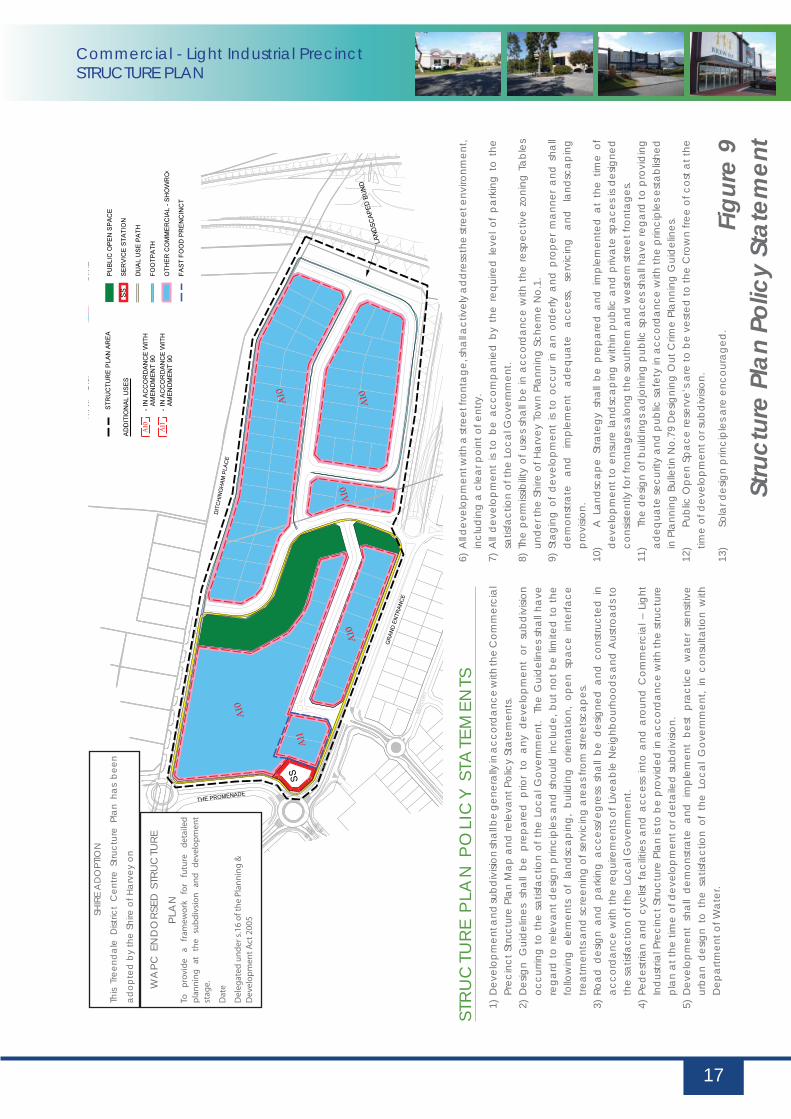
The Shire of Harvey Town Planning Scheme No.1 stipulates the need to prepare a structure plan prior to subdivision or development occurring. The structure plan and implementation provisions follow this section. (See Figures 9 & 10)
5.2 Zoning
It is proposed to rezone the land as part of town planning scheme amendment. This process will provide the statutory controls to guide future subdivision and development.
5.3 Subdivision
Subdivision is to occur generally in accordance with the structure plan. It is expected that design guidelines will be required as a condition of subdivision to control matters of detailed design for future development.
5.4 Development Approvals
Development shall be in accordance with the structure plan provisions, scheme requirements and approved Design Guidelines.
Commercial - Light Industrial PrecinctSTRUCTURE PLAN
17
STR
UC
TUR
E P
LAN
PO
LIC
Y S
TATE
MEN
TS1)
Dev
elop
men
t and
subd
ivisi
on sh
all b
e ge
nera
lly in
acc
ord
ance
with
the
Com
mer
cial
Pr
ecin
ct S
truct
ure
Plan
Map
and
rele
vant
Pol
icy
Stat
emen
ts.
2) D
esig
n G
uid
elin
es s
hall
be p
repa
red
prio
r to
any
dev
elop
men
t or
sub
div
ision
oc
curri
ng t
o th
e sa
tisfa
ctio
n of
the
Loc
al G
over
nmen
t. T
he G
uid
elin
es s
hall
have
re
gard
to
rele
vant
des
ign
prin
cipl
es a
nd s
houl
d in
clud
e, b
ut n
ot b
e lim
ited
to
the
follo
win
g el
emen
ts o
f la
ndsc
apin
g, b
uild
ing
orie
ntat
ion,
ope
n sp
ace
inte
rface
tre
atm
ents
and
scre
enin
g of
serv
icin
g ar
eas f
rom
stre
etsc
apes
. 3)
Roa
d d
esig
n an
d p
arki
ng a
cces
s/eg
ress
sha
ll be
des
igne
d a
nd c
onst
ruct
ed i
n ac
cord
ance
with
the
requ
irem
ents
of L
ivea
ble
Nei
ghbo
urho
ods
and
Aus
troad
s to
th
e sa
tisfa
ctio
n of
the
Loca
l Gov
ernm
ent.
4) P
edes
trian
and
cyc
list
faci
litie
s an
d a
cces
s in
to a
nd a
roun
d C
omm
erci
al –
Lig
ht
Ind
ustri
al P
reci
nct S
truct
ure
Plan
is to
be
prov
ided
in a
ccor
dan
ce w
ith th
e st
ruct
ure
plan
at t
he ti
me
of d
evel
opm
ent o
r det
aile
d su
bdiv
ision
.5)
Dev
elop
men
t sh
all
dem
onst
rate
and
im
plem
ent
best
pra
ctic
e w
ater
sen
sitiv
e ur
ban
des
ign
to t
he s
atisf
actio
n of
the
Loc
al G
over
nmen
t, in
con
sulta
tion
with
D
epar
tmen
t of W
ater
.
6) A
ll dev
elop
men
t with
a st
reet
fron
tage
, sha
ll act
ivel
y ad
dre
ss th
e st
reet
env
ironm
ent,
incl
udin
g a
clea
r poi
nt o
f ent
ry.
7) A
ll d
evel
opm
ent
is to
be
acco
mpa
nied
by
the
requ
ired
leve
l of
park
ing
to t
he
satis
fact
ion
of th
e Lo
cal G
over
nmen
t.8)
The
per
miss
ibilit
y of
use
s sh
all b
e in
acc
ord
ance
with
the
resp
ectiv
e zo
ning
Tab
les
und
er th
e Sh
ire o
f Har
vey
Tow
n Pl
anni
ng S
chem
e N
o.1.
9)
Sta
ging
of
dev
elop
men
t is
to o
ccur
in a
n or
der
ly a
nd p
rope
r m
anne
r an
d s
hall
dem
onst
rate
an
d
impl
emen
t ad
equa
te
acce
ss,
serv
icin
g an
d
land
scap
ing
prov
ision
. 10
) A
Lan
dsc
ape
Stra
tegy
sha
ll be
pre
pare
d a
nd i
mpl
emen
ted
at
the
time
of
dev
elop
men
t to
ensu
re la
ndsc
apin
g w
ithin
pub
lic a
nd p
rivat
e sp
aces
is d
esig
ned
co
nsist
ently
for f
ront
ages
alo
ng th
e so
uthe
rn a
nd w
este
rn st
reet
fron
tage
s.11
) Th
e d
esig
n of
bui
ldin
gs a
djo
inin
g pu
blic
spa
ces
shal
l hav
e re
gard
to p
rovi
din
g ad
equa
te se
curit
y an
d p
ublic
safe
ty in
acc
ord
ance
with
the
prin
cipl
es e
stab
lishe
d
in P
lann
ing
Bulle
tin N
o.79
Des
igni
ng O
ut C
rime
Plan
ning
Gui
del
ines
.12
) Pu
blic
Ope
n Sp
ace
rese
rve’
s are
to b
e ve
sted
to th
e C
row
n fre
e of
cos
t at t
he
time
of d
evel
opm
ent o
r sub
div
ision
.
13)
Sola
r des
ign
prin
cipl
es a
re e
ncou
rage
d.
Figu
re 9
Stru
ctur
e Pl
an P
olic
y St
atem
ent
SHIR
E A
DO
PTIO
N
This
Tree
ndal
e D
istric
t C
entre
Stru
ctur
e Pl
an h
as b
een
adop
ted
by
the
Shire
of H
arve
y on
WA
PC E
ND
ORS
ED S
TRU
CTU
RE
PLA
NTo
p
rovi
de
a fr
amew
ork
fo
r fu
ture
d
etai
led
p
lan
nin
g
at
the
sub
div
sio
n
and
d
evel
op
men
t st
age.
Dat
e
Del
egat
ed u
nd
er s
.16
of t
he
Plan
nin
g &
D
evel
op
men
t A
ct 2
005

Commercial - Light Industrial PrecinctSTRUCTURE PLAN
18
Figu
re 1
0Pr
ecin
ct P
lans
and
Sta
tem
ents
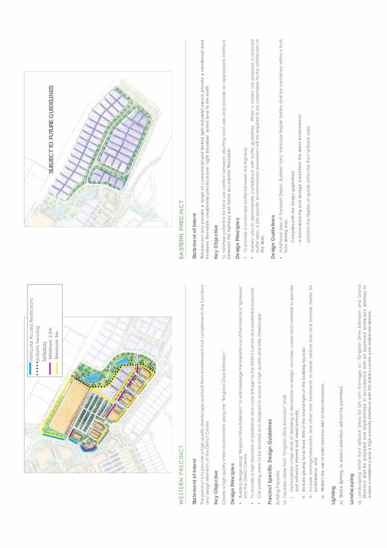
EAST
ERN
PR
ECIN
CT
Stat
emen
t of I
nten
tTh
is pr
ecin
ct is
to p
rovi
de
a ra
nge
of c
omm
erci
al a
nd li
mite
d li
ght i
ndus
trial
use
s to
pro
vid
e a
trans
ition
al a
rea
betw
een
Tree
ndal
e’s r
esid
entia
l pre
cinc
ts a
nd “
Light
Ind
ustri
al”
zone
d la
nd to
the
north
.
Key
Obj
ectiv
eTo
min
imise
pot
entia
l for
land
use
con
fl ict
bet
wee
n ab
uttin
g la
nd u
ses
and
pro
vid
e an
app
ropr
iate
inte
rface
be
twee
n th
e hi
ghw
ay a
nd fu
ture
acc
ess i
nto
Tree
ndal
e.
Desig
n Pr
inci
ples
• To
pro
vid
e a
land
scap
e bu
ffer b
etw
een
the
high
way
• N
urse
ry u
ses
to d
emon
stra
te c
ompl
ianc
e w
ith b
uffe
r gui
del
ines
. W
hen
a nu
rser
y us
e pr
opos
es a
red
uced
bu
ffer a
rea,
a si
te sp
ecifi
c en
viro
nmen
tal a
sses
smen
t will
be re
quire
d to
be
und
erta
ken
to th
e sa
tisfa
ctio
n of
th
e Sh
ire.
Desig
n G
uide
lines
• A
dd
ition
al U
ses
of T
rans
port
Dep
ot, B
uild
ers
Yard
, Veh
icul
ar R
epai
r Sta
tion
shal
l be
cont
aine
d w
ithin
a b
uilt
form
setti
ng th
at:
-
Com
plie
s with
the
des
ign
guid
elin
es
- sc
reen
s ser
vici
ng a
nd st
orag
e ar
eas f
rom
the
stre
et e
nviro
nmen
t;
-
proh
ibits
the
disp
lay
of g
ood
s with
in th
e fro
nt se
tbac
k ar
ea
WES
TER
N P
REC
INC
T
Stat
emen
t of I
nten
tTh
is pr
ecin
ct is
to p
rovi
de
a hi
gh q
ualit
y st
reet
scap
e an
d b
uilt
form
env
ironm
ent t
hat c
ompl
emen
ts th
e fu
nctio
ns
and
des
ign
elem
ents
of t
he D
istric
t Cen
tre
Key
Obj
ectiv
eC
reat
e a
high
qua
lity
stre
et e
nviro
nmen
t alo
ng th
e “K
ings
ton
Driv
e Ex
tens
ion”
.
Desig
n Pr
inci
ples
• Bu
ildin
g d
esig
n al
ong
“Kin
gsto
n D
rive
Exte
nsio
n” to
ack
now
led
ge th
e im
porta
nce
of th
e ro
ad a
s a “
gate
way
” in
to th
e D
istric
t Cen
tre.
• To
pro
vid
e a
high
stan
dar
d o
f ped
estri
an a
nd c
ycle
linka
ge to
the
Dist
rict C
entre
and
resid
entia
l sur
roun
ds
• C
ar p
arki
ng a
reas
to b
e lo
cate
d a
nd d
esig
ned
to e
nsur
e a
high
qua
lity
and
safe
stre
etsc
ape.
Prec
inct
Spe
cifi c
Des
ign
Gui
delin
esBu
ildin
g Fa
cad
esa)
Fac
ades
visi
ble
from
“Ki
ngst
on D
rive
Exte
nsio
n” sh
all:
i.
Dem
onst
rate
a h
igh
leve
l of d
etai
ling
or d
ecor
atio
n in
des
ign,
stru
ctur
e, c
olou
r and
mat
eria
ls to
pro
vid
e an
d e
nhan
ce in
tere
st a
nd v
isual
am
enity
; ii.
Inc
lud
e gl
azin
g fo
r at l
east
40%
of t
he to
tal le
ngth
of t
he b
uild
ing
faça
de;
iii.
In
clud
e aw
ning
s/ve
rand
ahs
and
oth
er r
oof
treat
men
ts t
o br
eak
verti
cal l
ines
and
pro
vid
e sh
elte
r fo
r pe
des
trian
s; a
ndiv
. Re
stric
t the
use
of r
olle
r doo
rs to
sid
e or
rear
ele
vatio
ns.
Light
ing
a) S
trobe
light
ing,
to a
ttrac
t atte
ntio
n, w
ill no
t be
perm
itted
.
Land
scap
ing
a) L
and
scap
ing
with
in f
ront
set
back
are
as f
or lo
ts w
ith f
ront
ages
on
“Kin
gsto
n D
rive
Exte
nsio
n an
d G
rand
En
tranc
e sh
all b
e pr
epar
ed a
nd im
plem
ente
d in
acc
ord
ance
with
an
appr
oved
land
scap
e st
rate
gy t
o en
sure
con
siste
ncy
and
a h
igh
amen
ity in
terfa
ce w
ith th
e d
istric
t cen
tre a
nd re
siden
tial s
treet
s.
Commercial - Light Industrial PrecinctSTRUCTURE PLAN
APPENDIX A
CERTIFICATE OF TITLES
LANDGATE COPY OF ORIGINAL NOT TO SCALE Tue Jul 24 08:50:24 2007 JOB 28763278
LANDGATE COPY OF ORIGINAL NOT TO SCALE Tue Jul 24 08:51:23 2007 JOB 28763304
LANDGATE COPY OF ORIGINAL NOT TO SCALE Tue Jul 24 08:51:23 2007 JOB 28763304

Commercial - Light Industrial PrecinctSTRUCTURE PLAN
APPENDIX B
ZONING TABLE EXTRACTS
Shi
re o
f Har
vey
TPS
1
Pag
e N
o. 6
0
TAB
LE 1
4 - Z
ON
ING
AN
D D
EVEL
OPM
ENT
STA
ND
AR
DS
ZO
NIN
G A
ND
DE
VE
LOP
ME
NT
STA
ND
AR
DS
O
THE
R C
OM
ME
RC
IAL
- SH
OW
RO
OM
P
OLI
CY
STA
TEM
EN
T In
tend
ed fo
r the
est
ablis
hmen
t of s
how
room
type
use
s, w
hich
are
inap
prop
riate
to th
e S
hop
Zone
bec
ause
of t
he la
rger
land
are
as re
quire
d, b
ut a
re n
ot s
uite
d to
In
dust
rial Z
ones
. D
EV
ELO
PM
EN
T S
TAN
DA
RD
S
MIN
IMU
M B
OU
ND
AR
Y S
ETB
AC
KS
Min
imum
Lo
t Are
as
Min
imum
E
ffect
ive
Fron
tage
Min
imum
Lot
ar
ea fo
r D
wel
ling
Uni
t
Fron
t R
ear
Sid
es
Min
imum
Car
P
arki
ng
Spa
ces
Min
imum
La
nd-
scap
ing
O
THE
R R
EQ
UIR
EM
EN
TS
For a
n ex
plan
atio
n of
sym
bols
refe
r to
Cla
use
4.
2.2
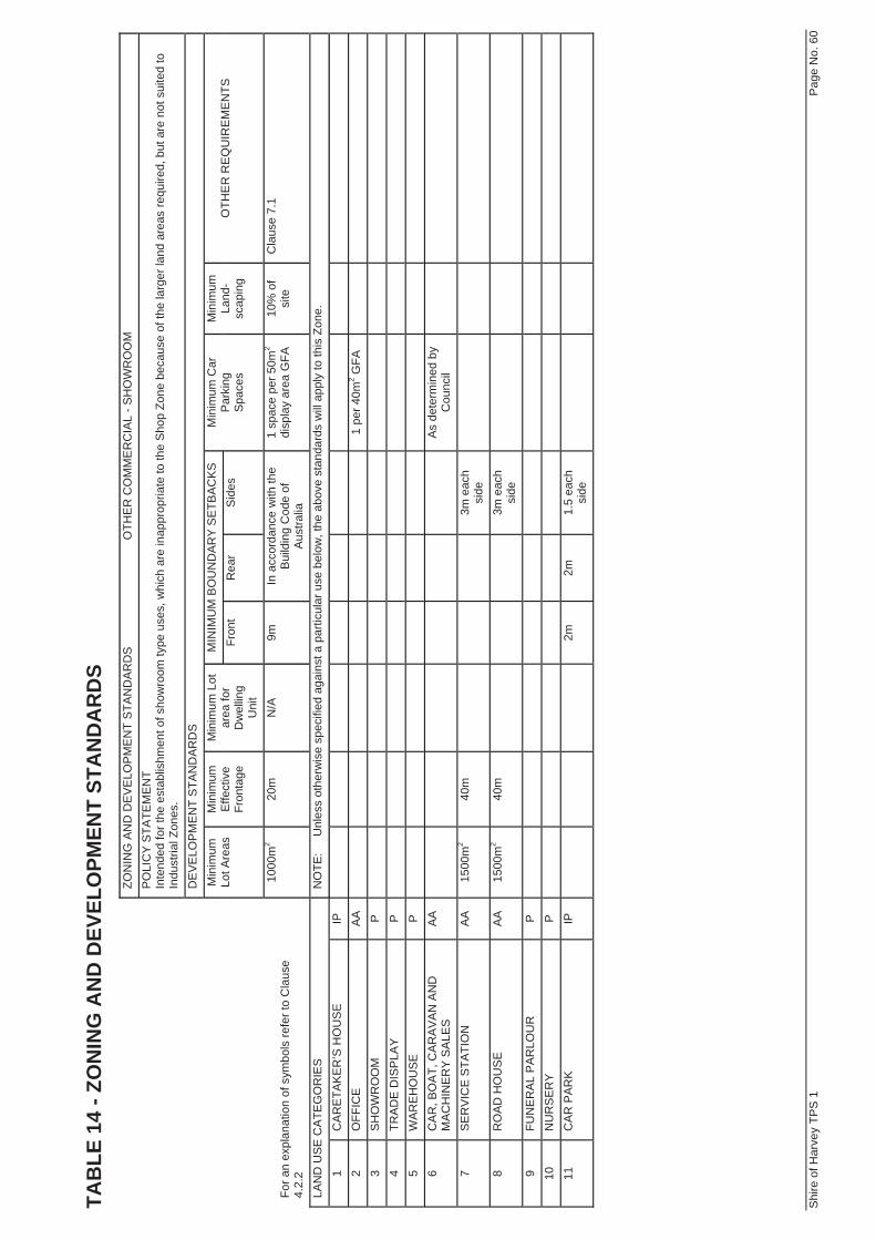
1000
m2
20m
N
/A
9m
In a
ccor
danc
e w
ith th
e B
uild
ing
Cod
e of
A
ustra
lia
1 sp
ace
per 5
0m2
disp
lay
area
GFA
10
% o
f si
te
Cla
use
7.1
LAN
D U
SE
CA
TEG
OR
IES
N
OTE
:
Unl
ess
othe
rwis
e sp
ecifi
ed a
gain
st a
par
ticul
ar u
se b
elow
, the
abo
ve s
tand
ards
will
app
ly to
this
Zon
e.
1 C
AR
ETA
KE
R’S
HO
US
E
IP
2
OFF
ICE
A
A
1 pe
r 40m
2 GFA
3
SH
OW
RO
OM
P
4 TR
AD
E D
ISP
LAY
P
5
WA
RE
HO
US
E
P
6
CA
R, B
OA
T, C
AR
AV
AN
AN
D
MA
CH
INE
RY
SA
LES
A
A
As
dete
rmin
ed b
y C
ounc
il
7 S
ER
VIC
E S
TATI
ON
A
A
1500
m2
40m
3m e
ach
side
8 R
OA
D H
OU
SE
A
A
1500
m2
40m
3m e
ach
side
9 FU
NE
RA
L P
AR
LOU
R
P
10
N
UR
SE
RY
P
11
C
AR
PA
RK
IP
2m
2m
1.5
each
si
de
Shi
re o
f Har
vey
TPS
1
Pag
e N
o. 6
1
TAB
LE 1
5 - Z
ON
ING
AN
D D
EVEL
OPM
ENT
STA
ND
AR
DS
ZO
NIN
G A
ND
DE
VE
LOP
ME
NT
STA
ND
AR
DS
O
THE
R C
OM
ME
RC
IAL
- SH
OW
RO
OM
(CO
NTI
NU
ED
) P
OLI
CY
STA
TEM
EN
T In
tend
ed fo
r the
est
ablis
hmen
t of s
how
room
type
use
s, w
hich
are
inap
prop
riate
to th
e S
hop
Zone
bec
ause
of t
he la
rger
land
are
as re
quire
d, b
ut a
re n
ot s
uite
d to
In
dust
rial Z
ones
. D
EV
ELO
PM
EN
T S
TAN
DA
RD
S
MIN
IMU
M B
OU
ND
AR
Y S
ETB
AC
KS
Min
imum
Lo
t Are
as
Min
imum
E
ffect
ive
Fron
tage
Min
imum
Lot
ar
ea fo
r D
wel
ling
Uni
t Fr
ont
Rea
r S
ides
M
inim
um C
ar
Par
king
Spa
ces
Min
imum
La
nd-
scap
ing
OTH
ER
RE
QU
IRE
ME
NTS
For a
n ex
plan
atio
n of
sym
bols
refe
r to
Cla
use
4.
2.2
1000
m2
20m
N
/A
9m
In a
ccor
danc
e w
ith th
e B
uild
ing
Cod
e of
A
ustra
lia
1 sp
ace
per 5
0m2
disp
lay
area
GFA
10
% o
f si
te
Cla
use
7.1
LAN
D U
SE
CA
TEG
OR
IES
N
OTE
:
Unl
ess
othe
rwis
e sp
ecifi
ed a
gain
st a
par
ticul
ar u
se b
elow
, the
abo
ve s
tand
ards
will
app
ly to
this
Zon
e.
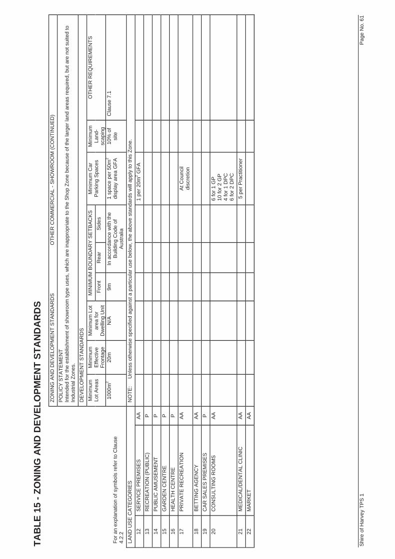
12
SE
RV
ICE
PR
EM
ISE
S
AA
1
per 2
0m2 G
FA
13
RE
CR
EA
TIO
N (P
UB
LIC
) P
14
PU
BLI
C A
MU
SE
ME
NT
P
15
G
AR
DE
N C
EN
TRE
P
16
HE
ALT
H C
EN
TRE
P
17
PR
IVA
TE R
EC
RE
ATI
ON
A
A
At C
ounc
il di
scre
tion
18
BE
TTIN
G A
GE
NC
Y A
A
19
C
AR
SA
LES
PR
EM
ISE
S
P
20
C
ON
SU
LTIN
G R
OO
MS
A
A
6 fo
r 1 G
P
10 fo
r 2 G
P
4 fo
r 1 D
PC
6
for 2
DP
C
21
ME
DIC
AL/
DE
NTA
L C
LIN
IC
AA
5
per P
ract
ition
er
22
MA
RK
ET
AA
Shi
re o
f Har
vey
TPS
1
Pag
e N
o. 6
2
TAB
LE 1
6 - Z
ON
ING
AN
D D
EVEL
OPM
ENT
STA
ND
AR
DS
ZO
NIN
G A
ND
DE
VE
LOP
ME
NT
STA
ND
AR
DS
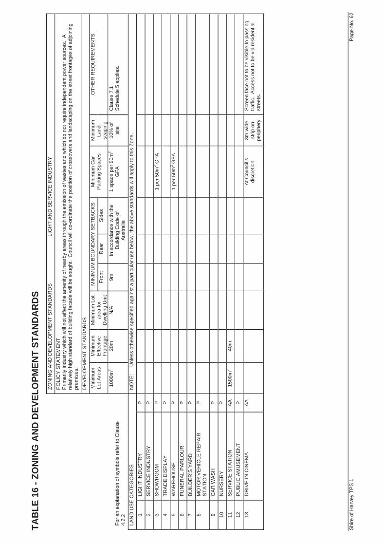
LI
GH
T A
ND
SE
RV
ICE
IND
US
TRY
PO
LIC
Y S
TATE
ME
NT
Prim
arily
indu
stry
whi
ch w
ill n
ot a
ffect
the
amen
ity o
f nea
rby
area
s th
roug
h th
e em
issi
on o
f was
tes
and
whi
ch d
o no
t req
uire
inde
pend
ent p
ower
sou
rces
. A
re
lativ
ely
high
sta
ndar
d of
bui
ldin
g fa
cade
will
be
soug
ht.
Cou
ncil
will
co-
ordi
nate
the
posi
tion
of c
ross
over
s an
d la
ndsc
apin
g on
the
stre
et fr
onta
ges
of a
djoi
ning
pr
emis
es.
DE
VE
LOP
ME
NT
STA
ND
AR
DS
MIN
IMU
M B
OU
ND
AR
Y S
ETB
AC
KS
Min
imum
Lo
t Are
as
Min
imum
E
ffect
ive
Fron
tage
Min
imum
Lot
ar
ea fo
r D
wel
ling
Uni
t Fr
ont
Rea
r S
ides
M
inim
um C
ar
Par
king
Spa
ces
Min
imum
La
nd-
scap
ing
OTH
ER
RE
QU
IRE
ME
NTS
For a
n ex
plan
atio
n of
sym
bols
refe
r to
Cla
use
4.
2.2
1000
m2
20m
N
/A
9m
In a
ccor
danc
e w
ith th
e B
uild
ing
Cod
e of
A
ustra
lia
1 sp
ace
per 5
0m2
GFA
10
% o
f si
te
Cla
use
7.1
Sch
edul
e 5
appl
ies.
LAN
D U
SE
CA
TEG
OR
IES
N
OTE
:
Unl
ess
othe
rwis
e sp
ecifi
ed a
gain
st a
par
ticul
ar u
se b
elow
, the
abo
ve s
tand
ards
will
app
ly to
this
Zon
e.
1 LI
GH
T IN
DU
STR
Y P
2 S
ER
VIC
E IN
DU
STR
Y P
3 S
HO
WR
OO
M
P
1 pe
r 50m
2 GFA
4
TRA
DE
DIS
PLA
Y P
5 W
AR
EH
OU
SE
P
1
per 5
0m2 G
FA
6 FU
NE
RA
L P
AR
LOU
R
P
7
BU
ILD
ER
’S Y
AR
D
P
8
MO
TOR
VE
HIC
LE R
EP
AIR
S
TATI
ON
P
9 C
AR
WA
SH
P
10
NU
RS
ER
Y P
11
SE
RV
ICE
STA
TIO
N
AA
15
00m
2 40
m
12
P
UB
LIC
AM
US
EM
EN
T P
13
DR
IVE
IN C
INE
MA
A
A
At C
ounc
il’s
disc
retio
n 3m
wid
e st
rip o
n pe
riphe
ry
Scr
een
face
not
to b
e vi
sibl
e to
pas
sing
tra
ffic.
Acc
ess
not t
o be
via
resi
dent
ial
stre
ets.
Shi
re o
f Har
vey
TPS
1
Pag
e N
o. 6
3
TAB
LE 1
7 - Z
ON
ING
AN
D D
EVEL
OPM
ENT
STA
ND
AR
DS
ZO
NIN
G A
ND
DE
VE
LOP
ME
NT
STA
ND
AR
DS
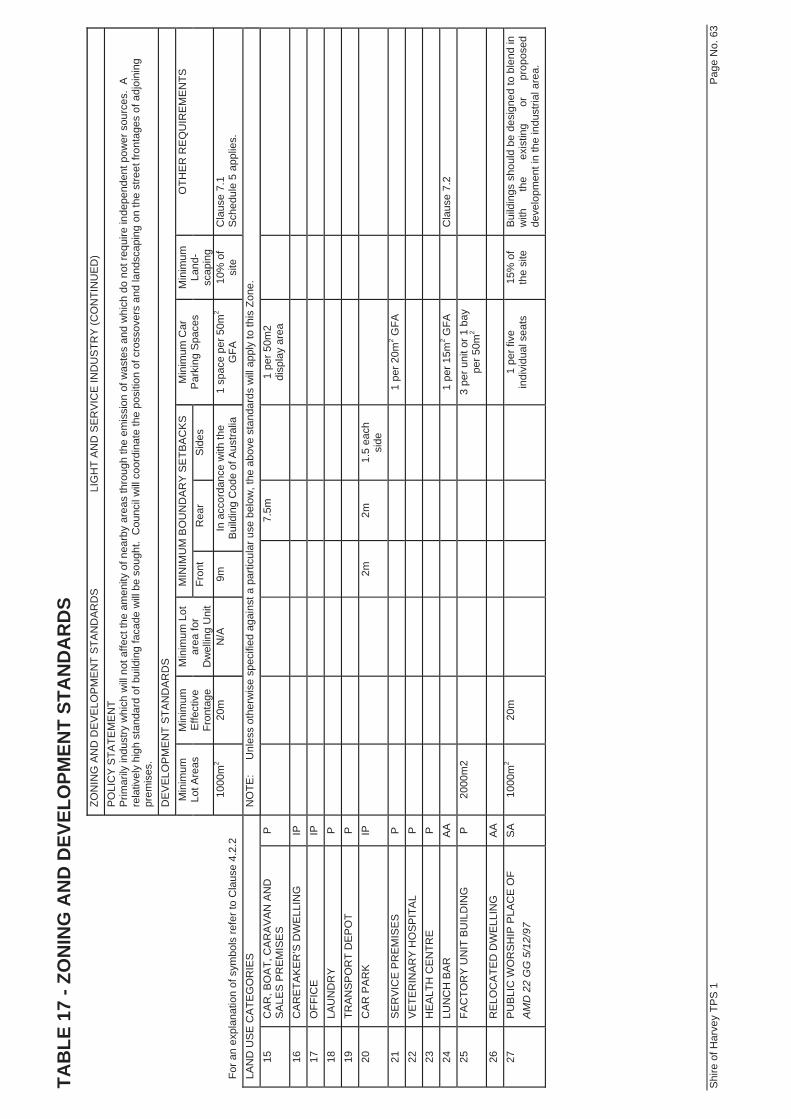
LI
GH
T A
ND
SE
RV
ICE
IND
US
TRY
(CO
NTI
NU
ED
) P
OLI
CY
STA
TEM
EN
T P
rimar
ily in
dust
ry w
hich
will
not
affe
ct th
e am
enity
of n
earb
y ar
eas
thro
ugh
the
emis
sion
of w
aste
s an
d w
hich
do
not r
equi
re in
depe
nden
t pow
er s
ourc
es.
A
rela
tivel
y hi
gh s
tand
ard
of b
uild
ing
faca
de w
ill b
e so
ught
. C
ounc
il w
ill c
oord
inat
e th
e po
sitio
n of
cro
ssov
ers
and
land
scap
ing
on th
e st
reet
fron
tage
s of
adj
oini
ng
prem
ises
. D
EV
ELO
PM
EN
T S
TAN
DA
RD
S
MIN
IMU
M B
OU
ND
AR
Y S
ETB
AC
KS
Min
imum
Lo
t Are
as
Min
imum
E
ffect
ive
Fron
tage
Min
imum
Lot
ar
ea fo
r D
wel
ling
Uni
t Fr
ont
Rea
r S
ides
M
inim
um C
ar
Par
king
Spa
ces
Min
imum
La
nd-
scap
ing
OTH
ER
RE
QU
IRE
ME
NTS
For a
n ex
plan
atio
n of
sym
bols
refe
r to
Cla
use
4.2.
2 10
00m
2 20
m
N/A
9m
In
acc
orda
nce
with
the
Bui
ldin
g C
ode
of A
ustra
lia
1 sp
ace
per 5
0m2
GFA
10
% o
f si
te
Cla
use
7.1
Sch
edul
e 5
appl
ies.
LA
ND
US
E C
ATE
GO
RIE
S
NO
TE:
U
nles
s ot
herw
ise
spec
ified
aga
inst
a p
artic
ular
use
bel
ow, t
he a
bove
sta
ndar
ds w
ill a
pply
to th
is Z
one.
15
C
AR
, BO
AT,
CA
RA
VA
N A
ND
S
ALE
S P
RE
MIS
ES
P
7.
5m
1
per 5
0m2
disp
lay
area
16
CA
RE
TAK
ER
’S D
WE
LLIN
G
IP
17
O
FFIC
E
IP
18
LA
UN
DR
Y
P
19
TR
AN
SP
OR
T D
EP
OT
P
20
C
AR
PA
RK
IP
2m
2m
1.5
each
si
de
21
SE
RV
ICE
PR
EM
ISE
S
P
1 pe
r 20m
2 GFA
22
V
ETE
RIN
AR
Y H
OS
PIT
AL
P
23
H
EA
LTH
CE
NTR
E
P
24
LU
NC
H B
AR
A
A
1 pe
r 15m
2 GFA
Cla
use
7.2
25
FAC
TOR
Y U
NIT
BU
ILD
ING
P
20
00m
2
3 pe
r uni
t or 1
bay
pe
r 50m
2
26
RE
LOC
ATE
D D
WE
LLIN
G
AA
27
PU
BLI
C W
OR
SH
IP P
LAC
E O
F AM
D 2
2 G
G 5
/12/
97
SA
10
00m
2 20
m
1 pe
r fiv
e in
divi
dual
sea
ts
15%
of
the
site
B
uild
ings
sho
uld
be d
esig
ned
to b
lend
in
with
th
e ex
istin
g or
pr
opos
ed
deve
lopm
ent i
n th
e in
dust
rial a
rea.
Shi
re o
f Har
vey
TPS
1
Pag
e N
o. 8
4
TAB
LE 3
8 - Z
ON
ING
AN
D D
EVEL
OPM
ENT
STA
ND
AR
DS
ZON
ING
AN
D D
EV
ELO
PM
EN
T S
TAN
DA
RD
S
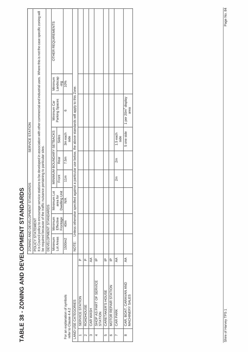
SE
RV
ICE
STA
TIO
N
PO
LIC
Y S
TATE
ME
NT
It is
Cou
ncil p
olic
y to
enc
oura
ge s
ervi
ce s
tatio
ns to
be
deve
lope
d in
ass
ocia
tion
with
oth
er c
omm
erci
al a
nd in
dust
rial u
ses.
Whe
re th
is is
not
the
case
spe
cific
zon
ing
will
be re
quire
d be
caus
e of
the
traffi
c nu
isan
ce p
erta
inin
g to
par
ticul
ar s
ites.
D
EV
ELO
PM
EN
T S
TAN
DA
RD
S
MIN
IMU
M B
OU
ND
AR
Y S
ETB
AC
KS
Min
imum
Lo
t Are
as
Min
imum
E
ffect
ive
Fron
tage
Min
imum
Lot
ar
ea fo
r D
wel
ling
Uni
t Fr
ont
Rea
r S
ides
M
inim
um C
ar
Par
king
Spa
ces
Min
imum
La
ndsc
ap-in
g
OTH
ER
RE
QU
IRE
ME
NTS
For a
n ex
plan
atio
n of
sym
bols
re
fer t
o C
laus
e 4.
4.2
1500
m2
40m
N
/A
11m
7.
5m
3m e
ach
side
6
10%
LAN
D U
SE
CA
TEG
OR
IES
N
OTE
:
Unl
ess
othe
rwis
e sp
ecifi
ed a
gain
st a
par
ticul
ar u
se b
elow
, the
abo
ve s
tand
ards
will
app
ly to
this
Zon
e.
1 S
ER
VIC
E S
TATI
ON
P
2 R
OA
DH
OU
SE
P
3 C
AR
WA
SH
A
A
4
SH
OP
AS
PA
RT
OF
SE
RV
ICE
S
TATI
ON
IP
5 C
AR
ETA
KE
R’S
HO
US
E
IP
6
MO
TOR
RE
PA
IR S
TATI
ON
IP
7 C
AR
PA
RK
A
A
2m
2m
1.
5 ea
ch
side
8 C
AR
, BO
AT,
CA
RA
VA
N A
ND
M
AC
HIN
ER
Y S
ALE
S
AA
5 on
e si
de
1 pe
r 20m
2 dis
play
ar
ea
Commercial - Light Industrial PrecinctSTRUCTURE PLAN
APPENDIX C
DESIGN GUIDELINES
EAST
ERN
PR
ECIN
CT
Stat
emen
t of I
nten
tTh
is pr
ecin
ct is
to p
rovi
de
a ra
nge
of c
omm
erci
al a
nd li
mite
d li
ght i
ndus
trial
use
s to
pro
vid
e a
trans
ition
al a
rea
betw
een
Tree
ndal
e’s r
esid
entia
l pre
cinc
ts a
nd “
Light
Ind
ustri
al”
zone
d la
nd to
the
north
.
Key
Obj
ectiv
e
betw
een
the
high
way
and
futu
re a
cces
s int
o Tr
eend
ale.
Desig
n Pr
inci
ples
the
Shire
.
Desig
n G
uide
lines
form
setti
ng th
at:
-
Com
plie
s with
the
des
ign
guid
elin
es
- sc
reen
s ser
vici
ng a
nd st
orag
e ar
eas f
rom
the
stre
et e
nviro
nmen
t;
Stat
emen
t of I
nten
t
Key
Obj
ectiv
e
Desig
n Pr
inci
ples
and
enh
ance
inte
rest
and
visu
al a
men
ity;
ii. I
nclu
de
glaz
ing
for a
t lea
st 4
0% o
f the
tota
l leng
th o
f the
bui
ldin
g fa
çad
e;
ped
estri
ans;
and
iv.
Rest
rict t
he u
se o
f rol
ler d
oors
to si
de
or re
ar e
leva
tions
.
Light
ing
a) S
trobe
light
ing,
to a
ttrac
t atte
ntio
n, w
ill no
t be
perm
itted
.
Land
scap
ing
Entra
nce
shal
l be
prep
ared
and
impl
emen
ted
in a
ccor
dan
ce w
ith a
n ap
prov
ed la
ndsc
ape
stra
tegy
to
ensu
re c
onsis
tenc
y an
d a
hig
h am
enity
inte
rface
with
the
dist
rict c
entre
and
resid
entia
l stre
ets.
Min
imum
2.5
m M
inim
um 5
mSU
BJEC
T TO
FUT
URE
GUI
DELI
NES

Commercial - Light Industrial PrecinctSTRUCTURE PLAN
Design Guidelines
Objectives
a) To develop and maintain an attractive Commercial Precinct fronting the “The Promenade”;
b) To provide a high standard of visual amenity and provide an attractive and complementary interface to the District Centre and residential frontages;
c) To achieve a cohesive built environment;d) To encourage development in a form that will give regard to security of property and the
safety of users; ande) To encourage buildings to address open space areas and provide passive surveillance
of car parking areas.
Application of Guidelines
a) The Guidelines apply to the area detailed in the Development Guide Plan referenced as number 11072P-MP-03; and
b) The Guidelines are to be read in conjunction with the Development Guide Plan and the relevant Scheme provisions applicable to the site.
Design Guideline Elements
The Commercial Precinct is divided into three distinctive precincts. Specifi c design objectives and elements relevant to each precinct are contained on the Development Guide Plan. General element provisions applicable to the entire Commercial Precinct are set out in the following Design Elements.
Where there is a confl ict between the intent of the general guidelines and the specifi c guidelines and elements presented on the Development Guide Plan, the specifi c guidelines and elements shall prevail.
General Guidelines
The general provisions of the Guidelines are set out in each of the following Design Elements:
Statement of Intent – Key Objective
The Commercial Precinct is to provide a high quality streetscape and built form environment that complements District Centre activity and provides a positive interface with open space environments and responds sympathetically with adjoining residential landholdings.
Commercial - Light Industrial PrecinctSTRUCTURE PLAN
ELEMENT 1 – STREETSCAPE AND BUILT FORM
Setbacks
a) Setbacks shall comply with the Detailed Guide Plan (DGP) where specifi cally mentioned. All other setbacks shall be determined in accordance with Table 14 of the Shire of Harvey Town Planning Scheme No.1;
b) Verandas and awnings may project up to 2.5 metres forward of the setback line and shall be a minimum of 2.75m above the foot path;
c) Setback areas shall only be used to contain car parking, landscaping and pedestrian access paths; and
d) Notwithstanding a) above, minor setback variations will be supported where they assist in breaking the linear form and provide interest.
d) Setback areas shall not be used for the storage of materials, products or by-products or wastes, the storage of fuel, machinery or plant equipment.
Building Height
a) A building shall not exceed a height of Category C of the Residential Planning Codes.
Facades and Structures
a) All elevations visible from the street are to include a high degree of architectural design detail at the pedestrian scale;
b) Long straight, unrelieved, horizontal lines should be broken by interesting design devices to suit a pedestrian environment and the building;
c) Plant rooms, servicing and storage areas shall be screened from the street environment; d) Roller doors shall generally be positioned to minimise impact on the street elevations. If
a roller door is required to address the street, it shall be restricted to a width of no greater than 6.5 metres; and
e) Transportable buildings shall be prohibited.
Windows/Glazing
a) The continuity of glazing on street elevations should be broken to provide interest by solid (opaque) vertical panels, framework and/or strong visual displays;
Entrance
a) Entrances to a building should be clearly visible from the street environment and should not be obscured by columns, planting or other features. Major doorways should be evident as such, with minor entrances also easily seen; and
b) Major entrances should include access for people of limited mobility. Access will be required as under the Building Code of Australia.

Commercial - Light Industrial PrecinctSTRUCTURE PLAN
Signage
a) All signage structures and signage shall be of a scale that refl ects the related development and be located and maintained in a manner that does not limit sightlines or create potential for public safety issues;
b) Signs should be integrated within the design of the building or the space in which it is proposed to be placed where practical;
c) Street numbering shall be integrated within the design of the building or the space in which it is proposed to be placed; and
d) Signage and advertising on glazed areas shall be limited to 30% of each street frontage. Signage and advertising on glazed areas shall be of a professional standard and of a style and theme consistent with other advertising integrated within the design of the building.
Colours
a) Colour should be used so that every building is different and interesting but not at the expense of its neighbours; and
b) Colour should differentiate between brick, render and wood surfaces and be used to highlight articulation or other architectural features where desirable.
Awnings and Verandahs
a) Weather protection on street frontage building façades is to be provided;b) Verandah roofs should be of solid light impenetrable material and should provide full
shade and shelter from sun, wind and rain; and c) If verandahs are provided, they and their supports, if any, should be designed to
complement the building’s architecture and scale.
Materials
a) Highly refl ective colorbond or zincalume roofs materials are not permitted;b) Use of external second hand materials shall not be permitted.
Fencing
a) Fencing abutting the Recreation reserve as defi ned on the Development Guide Plan shall be 1.8m high and consist of 1.8m high masonry piers with open picket infi ll above a 750mm high portion of masonry wall;
b) Side fencing abutting the “Public Purpose” site shall be constructed of 1.8m open mesh fencing with steel pole piers;
c) Front fencing is not supported, unless it is less than 750mm in height, matches with the design, material and colour of the building façade and forms part of a landscaping treatment;
Commercial - Light Industrial PrecinctSTRUCTURE PLAN
d) Side fencing forward of the building line shall be consistent with the theme of the building in terms of colour and materials, reducing at the building line to a 45 degree angle to a height not exceeding 1 metre; and
e) No fi bro cement fencing is permitted.
ELEMENT 2 – LANDSCAPING
Landscaping Plan
a) A detailed landscaping plan shall be required for developments. The plan shall include details of planting, lighting and paving. The design of the planting component must comply with the general guidelines outlined within this document. Information provided shall include all plant types clearly labelled and located, proposed numbers, sizes and spacing of plants and details of soil improvement and reticulation.
Street Frontages
a) Landscaping should be in the form of trees and low level plantings that will not block views between the road and buildings at eye level;
b) A minimum of 20% of the front setback area shall be landscaped; c) A minimum of 10% of secondary street setbacks areas shall be landscaped; andd) Landscaping is to apply “Waterwise” principles and predominantly incorporate native
plant species.
Car Parks
a) Any car parking or open areas facing streets shall be enhanced with extensive tree planting, lighting in accordance with relevant Australian Standards, paving etc so as to present a quality street frontage.
Lighting and Paving
a) All external lighting of buildings should be designed to complement the character of the streetscape; and
b) Paving should be used to enhance and identify pedestrian, cycle and vehicular access ways.
ELEMENT 3 – MOVEMENT AND PARKING
Pedestrian Movement
a) The pedestrian network shall provide a safe and attractive link between buildings and their respective parking areas; and
b) Development adjacent to footpaths and other pedestrian areas should provide an attractive and interesting frontage to the route. The use of blank walls, exhaust vents and mechanical equipment will not be supported where abutting pedestrian ways and street frontages.
Commercial - Light Industrial PrecinctSTRUCTURE PLAN
35
Parking and Access
a) Car parking bays shall be provided in accordance with the Shire of Harvey Town Planning Scheme No.1;
b) Vehicular access shall be restricted to points as generally indicated on the Development Guide Plan;
c) Sharing of crossovers is encouraged where practical; andd) All access ways and car parking areas are to be sealed or paved, marked and drained
to the satisfaction of the Local Government.
ELEMENT 4 – DEVELOPER APPROVAL
a) All building plans in the precinct covered by these design guidelines shall be subject to approval by the estate developer prior to being submitted to the Shire for planning approval and/or building licence.
MATTERS NOT CONSIDERED BY THE GUIDELINES
a) Wherever there are matters not considered or deemed questionable in these guidelines, the Shire of Harvey Town Planning Scheme No.1 shall prevail; and
b) If the matter is not resolved by a) above, then it shall be decided by the Shire of Harvey Council, unless a right of review is pursued by the proponent.