Embed Size (px)
Citation preview

PA C K A G E D E L E C T R I C / E L E C T R I C
LCHEnergence® Rooftop Units
50 HzBulletin No. 490152
March 2021 Supersedes June 2019
88 to 105 kW (25 to 30 Tons)Net Cooling Capacity − 74.4 to 88.5 kW (254 000 to 302 000 Btuh)
Optional Electric Heat - 23 to 91.9 kW
Factory Installed Electric Heat N = No Heat J = 23 kW Electric Heat K = 34.5 kW Electric Heat L = 45.9 kW Electric Heat P = 68.9 kW Electric Heat S = 91.9 kW Electric Heat
L C H 300 H 4 B S 1 M
Brand/Family L = Energence®
Unit Type C = Packaged Electric Cooling with optional Electric Heat
Major Design Sequence H = 1st Generation
Nominal Cooling Capacity - kW 300 = 88 kW
360 = 105 kW
Refrigerant Type 4 = R-410A
Blower Type B = Constant Air Volume (CAV) Belt Drive
Minor Design Sequence 1 = 1st Revision 2 = 2nd Revision 3 = 3rd Revision
Voltage M = 380/420V-3 phase-50Hz
Cooling Efficiency H = High Efficiency
LCH 88 TO 105 KW ROOFTOP UNITS
MODEL NUMBER IDENTIFICATION
C O M M E R C I A L P R O D U C T S P E C I F I C AT I O N S

Energence® Packaged Electric / Electric 88 to 105 kW - 50 Hz / Page 2
BB
DD EE
CC
FF
GG
HH
II
JJ
KK
LL
MM
NN
FEATURE HIGHLIGHTS
Lennox’ Energence® packaged rooftop unit product line was created to save energy with intelligence by offering some of the highest energy efficiency ratings available with a powerful, easy to use unit controller. This makes Energence rooftop units perfect for business owners looking for an Heating/Ventilation/Air Conditioning (HVAC) product with the lowest total cost of ownership.
Blower Data . . . . . . . . . . . . . . . . . . . . . . . . . . . . . . . . . . . . . . . . . . . . . . . . . . . . . . . . 18Dimensions . . . . . . . . . . . . . . . . . . . . . . . . . . . . . . . . . . . . . . . . . . . . . . . . . . . . . . . . 24
- Unit . . . . . . . . . . . . . . . . . . . . . . . . . . . . . . . . . . . . . . . . . . . . . . . . . . . . . . . . . . . 24 - Accessories . . . . . . . . . . . . . . . . . . . . . . . . . . . . . . . . . . . . . . . . . . . . . . . . . . . . . . 25
Electrical/Electric Heat Data . . . . . . . . . . . . . . . . . . . . . . . . . . . . . . . . . . . . . . . . . . . . . . . 22Electric Heat Capacities . . . . . . . . . . . . . . . . . . . . . . . . . . . . . . . . . . . . . . . . . . . . . . . . . 22Electric Heat Data . . . . . . . . . . . . . . . . . . . . . . . . . . . . . . . . . . . . . . . . . . . . . . . . . . . . . 22Optional Conventional Temperature Control Systems . . . . . . . . . . . . . . . . . . . . . . . . . . . . . . . . . 9Options / Accessories . . . . . . . . . . . . . . . . . . . . . . . . . . . . . . . . . . . . . . . . . . . . . . . . . . 11Outdoor Sound Data . . . . . . . . . . . . . . . . . . . . . . . . . . . . . . . . . . . . . . . . . . . . . . . . . . . 12Ratings . . . . . . . . . . . . . . . . . . . . . . . . . . . . . . . . . . . . . . . . . . . . . . . . . . . . . . . . . . . 16Specifications . . . . . . . . . . . . . . . . . . . . . . . . . . . . . . . . . . . . . . . . . . . . . . . . . . . . . . . 15Weight Data . . . . . . . . . . . . . . . . . . . . . . . . . . . . . . . . . . . . . . . . . . . . . . . . . . . . . . . . 12
- Unit . . . . . . . . . . . . . . . . . . . . . . . . . . . . . . . . . . . . . . . . . . . . . . . . . . . . . . . . . . . 12 - Options / Accessories. . . . . . . . . . . . . . . . . . . . . . . . . . . . . . . . . . . . . . . . . . . . . . . . . 12
CONTENTS
1. Scroll Compressors2. Condenser Coil3. Thermal Expansion Valves4. Filters/Driers5. Outdoor Coil Fan Motors6. Construction7. Hinged Access Panels8. Blower9. Electric Heat10. Air Filters11. Unit Controller12. Economizer13. Downflow Barometric Relief
Dampers

Energence® Packaged Electric / Electric 88 to 105 kW - 50 Hz / Page 3
• Components bonded for grounding to meet safety standards for servicing required by Underwriters Laboratories (UL) and the International Electrotechnical Commission (IEC)
• Cooling performance is rated at test conditions included in Air-Conditioning, Heating and Refrigeration (AHRI) Standard 340/360-2007 while operating at rated voltage and air volumes. International Organization for Standardization (ISO) 9001
• Registered Manufacturing Quality System
COOLING SYSTEM• Designed to maximize sensible and latent cooling
performance at design conditions• System can operate from –18°C to 52°C without any
additional controls
R-410A Refrigerant • Non-chlorine• Ozone friendly• Unit pre-charged with refrigerant; see Specification table
Scroll Compressors• Scroll compressors on all models for high performance,
reliability and quiet operation• Resiliently mounted on rubber grommets for quiet
operation
Compressor Crankcase Heaters• Protects against refrigerant migration that can occur
during low ambient operation or during extended off cycles
Condenser Coil - Lennox’ Environ™ Coil System • Lightweight, all aluminum brazed
fin construction• Constructed of three components
• A flat extrusion tube• Fins in-between the flat
extrusion tube• Two refrigerant manifolds
Environ™ Coil System Features:• Improved heat transfer performance due to high primary
surface area (flat tubes) versus secondary surface (fins)• Smaller internal volume (reduced refrigerant charge)• High durability• All aluminum construction• Fewer brazed joints• Compact design• Reduced unit weight• Easy maintenance/cleaning• Face split design• Mounting brackets with rubber inserts• Angled cabinet design protects coil from damage
BB
CC
FEATURES AND BENEFITSEvaporator Coil• Copper tube construction• Enhanced rippled-edge aluminum fins• Flared shoulder tubing connections• Silver-soldered construction • Factory leak tested• Cross row circuiting with rifled tubing • Low fin per inch count minimizes air pressure dropNOTE - All models have face-split evaporator coils
designed to keep condensate water off of an inactive part of the coil so the condensate will not re-enter the air stream.
Thermal Expansion Valves• Ensures optimal performance throughout the application
range• Removable element head
Filter/Driers• High capacity filter/drier protects the system from dirt
and moisture
High Pressure Switches• Protects the compressor from overload conditions such
as dirty condenser coils, blocked refrigerant flow, or loss of outdoor fan operation
Low Pressure Switches• Protects the compressors from low pressure conditions
such as low refrigerant charge, or low/no airflow
Condensate Drain Pan• Plastic, sloped drain pan• Side drain connectionsNOTE - Stainless steel drain pan available as a factory
installed option.
Freezestats• Protects the evaporator coil from damaging ice build-
up due to conditions such as low/no airflow, or low refrigerant charge
Outdoor Coil Fan Motors• Thermal overload protected• Totally enclosed• Permanently lubricated ball bearings• Shaft up• Wire basket mount
Outdoor Coil Fans• Polyvinyl chloride (PVC) coated fan guard furnished
DD
EE
FF
PERFORMANCE/QUALITY
Energence® Packaged Electric / Electric 88 to 105 kW - 50 Hz / Page 4
FEATURES AND BENEFITS
COOLING SYSTEM (continued)
Required Selections
Cooling Capacity• Specify nominal cooling capacity
Options/Accessories
Factory InstalledDischarge Air Temperature Sensor• Sensor sends information to the unit controller to
cycle up to 2 stages of heating or 4 stages of cooling to maintain the discharge air setpoints for heating or cooling
• Optional for units with single zone or bypass zoning control
NOTE - Sensor is shipped with the unit for remote field installation in the supply duct.
Factory or Field InstalledCondensate Drain Trap• Field installed only, may be factory enclosed to ship with
unit• Available in copper or Polyvinyl chloride (PVC)
Drain Pan Overflow Switch• Monitors condensate level in drain pan• Shuts down unit if drain becomes clogged
Stainless Steel Drain Pan• Non-corrosive drain pan
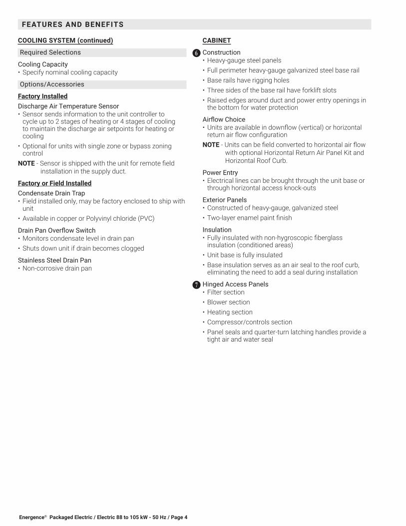
CABINET
Construction• Heavy-gauge steel panels • Full perimeter heavy-gauge galvanized steel base rail• Base rails have rigging holes• Three sides of the base rail have forklift slots• Raised edges around duct and power entry openings in
the bottom for water protection
Airflow Choice• Units are available in downflow (vertical) or horizontal
return air flow configurationNOTE - Units can be field converted to horizontal air flow
with optional Horizontal Return Air Panel Kit and Horizontal Roof Curb.
Power Entry• Electrical lines can be brought through the unit base or
through horizontal access knock-outs
Exterior Panels• Constructed of heavy-gauge, galvanized steel • Two-layer enamel paint finish
Insulation• Fully insulated with non-hygroscopic fiberglass
insulation (conditioned areas)• Unit base is fully insulated• Base insulation serves as an air seal to the roof curb,
eliminating the need to add a seal during installation
Hinged Access Panels• Filter section• Blower section• Heating section• Compressor/controls section• Panel seals and quarter-turn latching handles provide a
tight air and water seal
GG
HH

Energence® Packaged Electric / Electric 88 to 105 kW - 50 Hz / Page 5
FEATURES AND BENEFITS
BLOWER• A wide selection of supply air blower options are
available to meet a variety of airflow requirements
Motor• Overload protected• Ball bearings• Belt drive motors are offered on all models and are
available in several different sizes to maximize air performance
Supply Air Blower• Forward curved blades• Double inlet• Adjustable pulley (allows speed change)• Blower assembly slides out of unit for servicing• Grease fittings furnished
Required Selections• Specify motor output and drive kit number when base
unit is ordered, see Drive Kit Specifications tables• Order one drive kit, see Drive Kit Specifications Table
Options/Accessories
Factory InstalledBlower Belt Auto-Tensioner• Provides proper tension to belt drive blower belt without
the need for regular adjustments• Maintains airflow and proper performance
Field InstalledSupply Static Limit Switch• Field installed manual reset switch for supply static high
pressure limit• Prevents exceeding pressure limit in supply air duct.
Optional Mounting Kit includes tubing and adaptors
ELECTRICALNOTE - All units include terminal block and fuse block in
power entry junction box for single power entry application.
SmartWire™ System• Keyed and color-coded to prevent miswiring• Wire coloring scheme is standardized across all models• Each connection is intuitively labeled to make
troubleshooting and servicing quick and easy
Required Selections
Voltage Choice• Specify when ordering base unit
Options/Accessories
Factory or Field InstalledElectric Heat• Electric heat is CE marked• Helix wound nichrome elements• Individual element limit controls
II
JJ
• Wiring harness• Unit fuse block• See Options/Accessories tables for ordering information
Options/Accessories
Factory InstalledCorrosion Protection• A completely flexible immersed coating with an
electrodeposited dry film process (AST ElectroFin E-Coat); meets Mil Spec MIL-P-53084, ASTM B117 Standard Method Salt Spray Testing
• Indoor Corrosion Protection:• Coated coil• Painted blower housing• Painted indoor base
• Outdoor Corrosion Protection:• Coated coil• Painted outdoor base
Combination Coil/Hail Guards• Heavy gauge steel frame painted to match cabinet with
expanded metal mesh to protect the outdoor coil from damage
Grille Guards• Protects the space between outdoor coils and main
cabinet
Horizontal Return Air Panel Kit• Required for horizontal applications with Horizontal
Roof Curb, contains panel with return air opening for field replacement of existing unit panel and panel to cover bottom return air opening in unit, see dimension drawings
INDOOR AIR QUALITY
Air Filters• Disposable 51 mm filters furnished as standard
Options/Accessories
Factory or Field InstalledHealthy Climate® High Efficiency Air Filters• Disposable MERV 8 or MERV 13 (Minimum Efficiency
Reporting Value based on ASHRAE 52.2) efficiency 51 mm pleated filters
Replacement Filter Media Kit With Frame• Replaces existing pleated filter media• Includes washable metal mesh screen and metal frame
with clip for holding replaceable non-pleated filter
Field InstalledIndoor Air Quality (CO2) Sensors• Monitors CO2 levels, reports to the Prodigy® Unit
Controller, which adjusts economizer dampers as needed
KK
Energence® Packaged Electric / Electric 88 to 105 kW - 50 Hz / Page 6
CONTROL SYSTEM
PRODIGY UNIT CONTROLLER
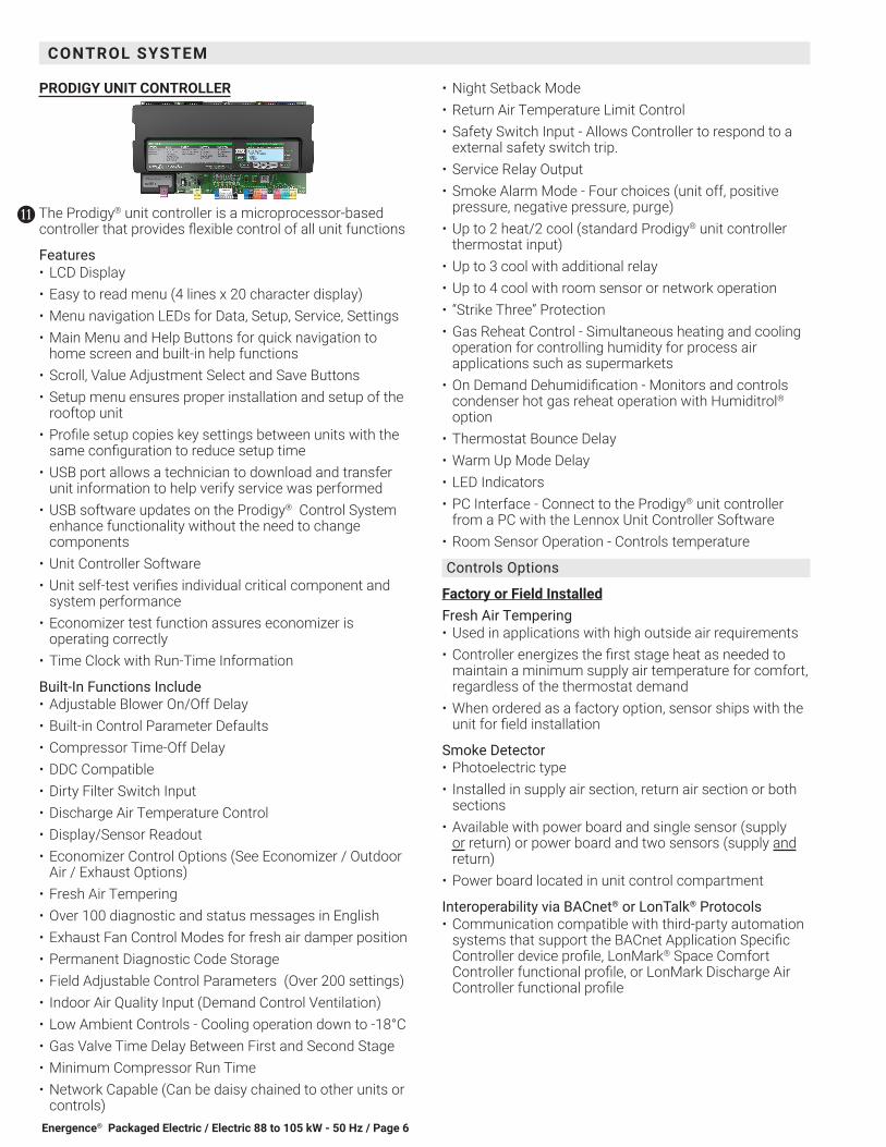
The Prodigy® unit controller is a microprocessor-based controller that provides flexible control of all unit functions
Features• LCD Display• Easy to read menu (4 lines x 20 character display)• Menu navigation LEDs for Data, Setup, Service, Settings• Main Menu and Help Buttons for quick navigation to
home screen and built-in help functions• Scroll, Value Adjustment Select and Save Buttons• Setup menu ensures proper installation and setup of the
rooftop unit• Profile setup copies key settings between units with the
same configuration to reduce setup time• USB port allows a technician to download and transfer
unit information to help verify service was performed• USB software updates on the Prodigy® Control System
enhance functionality without the need to change components
• Unit Controller Software• Unit self-test verifies individual critical component and
system performance• Economizer test function assures economizer is
operating correctly• Time Clock with Run-Time Information
Built-In Functions Include• Adjustable Blower On/Off Delay• Built-in Control Parameter Defaults• Compressor Time-Off Delay• DDC Compatible• Dirty Filter Switch Input• Discharge Air Temperature Control• Display/Sensor Readout• Economizer Control Options (See Economizer / Outdoor
Air / Exhaust Options)• Fresh Air Tempering• Over 100 diagnostic and status messages in English• Exhaust Fan Control Modes for fresh air damper position• Permanent Diagnostic Code Storage• Field Adjustable Control Parameters (Over 200 settings)• Indoor Air Quality Input (Demand Control Ventilation) • Low Ambient Controls - Cooling operation down to -18°C• Gas Valve Time Delay Between First and Second Stage• Minimum Compressor Run Time• Network Capable (Can be daisy chained to other units or
controls)
LL
• Night Setback Mode• Return Air Temperature Limit Control• Safety Switch Input - Allows Controller to respond to a
external safety switch trip.• Service Relay Output• Smoke Alarm Mode - Four choices (unit off, positive
pressure, negative pressure, purge)• Up to 2 heat/2 cool (standard Prodigy® unit controller
thermostat input)• Up to 3 cool with additional relay• Up to 4 cool with room sensor or network operation• “Strike Three” Protection• Gas Reheat Control - Simultaneous heating and cooling
operation for controlling humidity for process air applications such as supermarkets
• On Demand Dehumidification - Monitors and controls condenser hot gas reheat operation with Humiditrol® option
• Thermostat Bounce Delay• Warm Up Mode Delay• LED Indicators• PC Interface - Connect to the Prodigy® unit controller
from a PC with the Lennox Unit Controller Software• Room Sensor Operation - Controls temperature
Controls Options
Factory or Field InstalledFresh Air Tempering• Used in applications with high outside air requirements• Controller energizes the first stage heat as needed to
maintain a minimum supply air temperature for comfort, regardless of the thermostat demand
• When ordered as a factory option, sensor ships with the unit for field installation
Smoke Detector• Photoelectric type• Installed in supply air section, return air section or both
sections• Available with power board and single sensor (supply
or return) or power board and two sensors (supply and return)
• Power board located in unit control compartment
Interoperability via BACnet® or LonTalk® Protocols• Communication compatible with third-party automation
systems that support the BACnet Application Specific Controller device profile, LonMark® Space Comfort Controller functional profile, or LonMark Discharge Air Controller functional profile
Energence® Packaged Electric / Electric 88 to 105 kW - 50 Hz / Page 7
ECONOMIZER• Economizer operation is set and controlled by the
Prodigy® Unit Controller• Simple plug-in connections from economizer to unit
controller for easy installationNOTE - Optional sensors may be used instead of unit
sensors to determine whether outdoor air is suitable for free cooling. See Options/Accessories table.
Factory or Field InstalledHigh Performance• Low leakage dampers are Air Movement and Control
Association International (AMCA) Class 1A Certified - Maximum 3 CFM per sq. ft. leakage at 1 in. w.g.
• Gear-driven action• High torque 24-volt fully-modulating spring return
damper motor• Return air and outdoor air dampers• Plug-in connections to unit• Stainless steel bearings• Enhanced neoprene blade edge seals• Flexible stainless steel jamb sealsNOTE - Refer to Installation Instructions for complete
setup information.
Differential Sensible Control• Factory setting• Uses outdoor air and return air sensors that are
furnished with the unit• The Prodigy® Unit Controller compares outdoor air and
return air • When the outdoor air is below the configured setpoint
and cooler than return air, the controller activates the economizer
NOTE - Differential Sensible Control can be configured in the field to provide Offset Differential Sensible Control or Single Sensible Control.
NOTE - In Offset Differential Sensible Control mode, the economizer is enabled if the temperature differential (offset) between outdoor air and return air reaches the configured setpoint. In Single Sensible Control mode, the economizer is enabled when outdoor air temperature falls below the configured setpoint.
NOTE - The Free Cooling default setting for outdoor air temperature sensor is 13°C.
Global Control• The unit controller communicates with a DDC system
with one global sensor (enthalpy or sensible)• Determines whether outside air is suitable for free
cooling on all units connected to the control system• Sensor must be field provided
MM Factory or Field InstalledSingle Enthalpy Temperature Control• Outdoor air enthalpy sensor enables Economizer if the
outdoor enthalpy is less than the setpoint of the control
Differential Enthalpy Control• Order two Single Enthalpy Controls• One is field installed in the return air section• One is installed in the outdoor air section• Allows the economizer control to select between
outdoor air or return air, whichever has lower enthalpy
EXHAUST
Factory or Field InstalledDownflow Barometric Relief Dampers• Allow relief of excess air• Aluminum blade dampers prevent blow back and
outdoor air infiltration during off cycle• Bird screen furnished• Exhaust hood for downflow barometric relief dampers is
factory installed when dampers are factory installed with economizer
• Exhaust hood is furnished with dampers when ordered for field installation
Standard Static Power Exhaust Fans• Three, 0.25 kW motors • 508 mm propeller-type fans• Five blades• Total power input of 1125 W and a total air volume of
6040 L/s at 0 Pa.• Motor is inherently protected • Totally enclosed• Installs internal to unit for downflow applications only
with economizer option• Provides exhaust air pressure relief• Interlocked to run when return air dampers are closed
and supply air blower is operating• Fan runs based on air damper position (adjustable)• Motor inherently protected• Steel cabinet and hood painted to match unitNOTE - Requires optional Downflow Economizer
Barometric Relief Dampers. See Standard Static Power Exhaust Blower Tables.
Horizontal Barometric Relief Dampers• For use when unit is configured for horizontal
applications requiring an economizer• Allows relief of excess air• Aluminum blade dampers prevent blow back and
outdoor air infiltration during off cycle• Field installed in return air duct• Bird screen and hood furnishedNOTE - Horizontal Economizer Conversion kit is available
for field installation.
NN
OPTIONS / ACCESSORIES
Energence® Packaged Electric / Electric 88 to 105 kW - 50 Hz / Page 8
OPTIONS / ACCESSORIES
OUTDOOR AIR
Factory or Field InstalledOutdoor Air Damper - Downflow or Horizontal With Air Hood• Linked mechanical dampers• 0 to 25% (fixed) outdoor air adjustable• Installs in unit• Includes outdoor air hood• Automatic model features fully modulating spring return
damper motor with plug-in connection• Manual model features parallel blade, gear-driven
dampers with adjustable fixed positionNOTE - Minimum mixed air temperature in heating mode
is -1°C. Maximum mixed air temperature in cooling mode is 32°C.
ROOF CURBS• Nailer strip furnished• Mates to unit• US National Roofing Contractors Approved• Shipped knocked down
DownflowHybrid Roof Curbs• Interlocking tabs to fasten corners together• No tools required• Curb can also be fastened together with furnished
hardware• Available in 356, 457, and 610 mm heightsNOTE - See Options/Accessories table.
Horizontal• Converts unit from downflow to horizontal (side) air flow• Return air is on unit, supply air is on curb, see dimension
drawings• Available in 940 mm and 1041 mm heightsNOTE - Requires Horizontal Return Air Panel KitNOTE - Optional Insulation Kit is available to help prevent
sweating.
CEILING DIFFUSERS
Field InstalledCeiling Diffusers (Flush or Step-Down)• White powder coat finish on diffuser face and grilles• Insulated UL listed duct liner• Diffuser box has collars for duct connection• Step-down diffusers have double deflection blades• Flush diffusers have fixed blades• Provisions for suspending• Internally sealed to prevent recirculation• Removable return air grille• Adapts to T-bar ceiling grids or plaster ceilings
Transitions (Supply and Return)• Used with diffusers• Installs in roof curb• Galvanized steel construction• Flanges furnished for duct connection to diffusers• Fully insulated

Energence® Packaged Electric / Electric 88 to 105 kW - 50 Hz / Page 9
OPTIONAL CONVENTIONAL TEMPERATURE CONTROL SYSTEMS
ComfortSense® 8500 Commercial 7-Day Programmable Thermostat
• Fully Communicating Sensor• Full Color Touchscreen Interface• Variable Speed System Control (On Compatible Units)• Up To 4 Heat / 4 Cool• Built-In Sensors For Temperature, Humidity And Optional
CO2• Remote Sensor Options For Occupancy, Temperature• BACnet Capable Options• 5-2 or 7-Day Scheduling • Smooth Setback Recovery• Heat/Cool Auto-Changeover• Four-Wire Installation• FDD, ASHRAE, IECC Compliant
ComfortSense® 7500 Commercial 7-Day Programmable Thermostat
• Premium Universal Thermostat• Full Color Touchscreen Interface• Up To 4 Heat / 4 Cool• Built-In Sensors For Temperature and Humidity• Remote Sensors Options For Temperature, Discharge
Air, Outdoor Air• 5-2 or 7-Day Scheduling • Smooth Setback Recovery• Heat/Cool Auto-Changeover• FDD, ASHRAE, IECC Compliant
ComfortSense® 3000 Commercial 5-2 Day Programmable Thermostat
MAINT
Commercial
• Conventional Multi-Stage Thermostat• Intuitive Display• Push-Button Operation• Up To 2 Heat / 2 Cool• Built-In Temperature Sensor• Remote Temperature Sensing• Up to 5-2 Day Scheduling • Smooth Setback Recovery• Heat/Cool Auto-changeover
Wired Room Sensor (LCS-5030)
• Simple Push-Button Override• Variable Speed System Control (On Compatible Units)• Up To 4 Heat / 4 Cool• Built-In Temperature and Humidity Sensors• AA Battery / 24VAC Powered• SBUS Wired Operation• Automatic Sensor Averaging• Locking Hex Screw

Energence® Packaged Electric / Electric 88 to 105 kW - 50 Hz / Page 10
OPTIONAL CONVENTIONAL TEMPERATURE CONTROL SYSTEMSDescription Catalog No.ComfortSense® 8500 Commercial 7 Day Programmable ThermostatCS8500 7-Day Thermostat No CO2 Sensing 17G75
With CO2 Sensing 17G76Sensors/Accessories ¹ Remote non-adjustable wall-mount 10k 47W37
¹ Remote non-adjustable wall-mount 11k 94L61Sysbus Network Cable (Yellow) for ComfortSense 8500 and LCS-5030 Wired Room SensorTwisted pair 100% shielded communication cable, Red and Black 22 AWG, yellow jacket, rated at 75°C, 300V, Plenum rated Insulation - Low smoke PVC, NEC, CMP
500 ft. box 27M191000 ft. box 94L632500 ft. roll 68M25
ComfortSense® 7500 Commercial 7-Day Programmable ThermostatCS7500 7-Day Thermostat 17G74Sensors/Accessories ² Remote non-adjustable wall-mount 20k 47W36
² Remote non-adjustable wall-mount 10k 47W37Remote non-adjustable discharge air (duct mount) 19L22
Outdoor temperature sensor X2658ComfortSense® 3000 Commercial 5-2 Day Programmable ThermostatCS3000 5-2 Day Thermostat 11Y05Sensors/Accessories Remote non-adjustable wall mount 10k averaging 47W37
Thermostat wall mounting plate X2659ComfortSense® Non-Programmable ThermostatCS3000 Non-Programmable Thermostat 51M32Universal Thermostat Guard with Lock (clear)
Inside Dimensions (H x W) 5 7/8 x 8 3/8 in. 39P21Wired Room SensorLCS-5030 Wired Room Sensor 21L071 Up to nine of the same type remote temperature sensors can be connected in parallel.2 R emote wall-mount sensors can be applied in any of the following combinations:
One Sensor - (1) 47W36, Two Sensors - (2) 47W37, Three Sensors - (2) 47W36 and (1) 47W37 Four Sensors - (4) 47W36, Five Sensors - (3) 47W36 and (2) 47W37
Energence® Packaged Electric / Electric 88 to 105 kW - 50 Hz / Page 11
OPTIONS / ACCESSORIES
Item Description Model Number
Catalog Number
Unit Model No300 360
COOLING SYSTEM
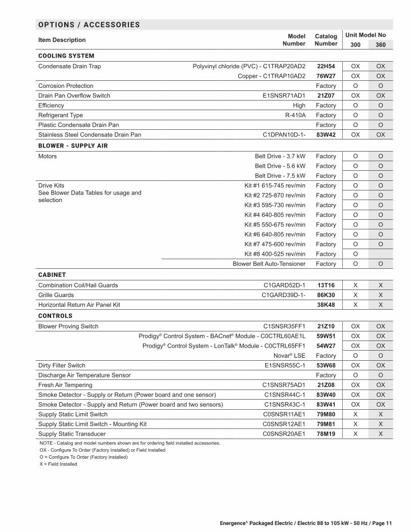
Condensate Drain Trap Polyvinyl chloride (PVC) - C1TRAP20AD2 22H54 OX OXCopper - C1TRAP10AD2 76W27 OX OX
Corrosion Protection Factory O ODrain Pan Overflow Switch E1SNSR71AD1 21Z07 OX OXEfficiency High Factory O ORefrigerant Type R-410A Factory O OPlastic Condensate Drain Pan Factory O OStainless Steel Condensate Drain Pan C1DPAN10D-1- 83W42 OX OX
BLOWER - SUPPLY AIR
Motors Belt Drive - 3.7 kW Factory O OBelt Drive - 5.6 kW Factory O OBelt Drive - 7.5 kW Factory O O
Drive Kits See Blower Data Tables for usage and selection
Kit #1 615-745 rev/min Factory O OKit #2 725-870 rev/min Factory O OKit #3 595-730 rev/min Factory O OKit #4 640-805 rev/min Factory O OKit #5 550-675 rev/min Factory O OKit #6 640-805 rev/min Factory O OKit #7 475-600 rev/min Factory O OKit #8 400-525 rev/min Factory O
Blower Belt Auto-Tensioner Factory O O
CABINET
Combination Coil/Hail Guards C1GARD52D-1 13T16 X XGrille Guards C1GARD39D-1- 86K30 X XHorizontal Return Air Panel Kit 38K48 X X
CONTROLS
Blower Proving Switch C1SNSR35FF1 21Z10 OX OXProdigy® Control System - BACnet® Module - C0CTRL60AE1L 59W51 OX OX
Prodigy® Control System - LonTalk® Module - C0CTRL65FF1 54W27 OX OXNovar® LSE Factory O O
Dirty Filter Switch E1SNSR55C-1 53W68 OX OXDischarge Air Temperature Sensor Factory O OFresh Air Tempering C1SNSR75AD1 21Z08 OX OXSmoke Detector - Supply or Return (Power board and one sensor) C1SNSR44C-1 83W40 OX OXSmoke Detector - Supply and Return (Power board and two sensors) C1SNSR43C-1 83W41 OX OXSupply Static Limit Switch C0SNSR11AE1 79M80 X XSupply Static Limit Switch - Mounting Kit C0SNSR12AE1 79M81 X XSupply Static Transducer C0SNSR20AE1 78M19 X XNOTE - Catalog and model numbers shown are for ordering field installed accessories.OX - Configure To Order (Factory Installed) or Field InstalledO = Configure To Order (Factory Installed)X = Field Installed
Energence® Packaged Electric / Electric 88 to 105 kW - 50 Hz / Page 12
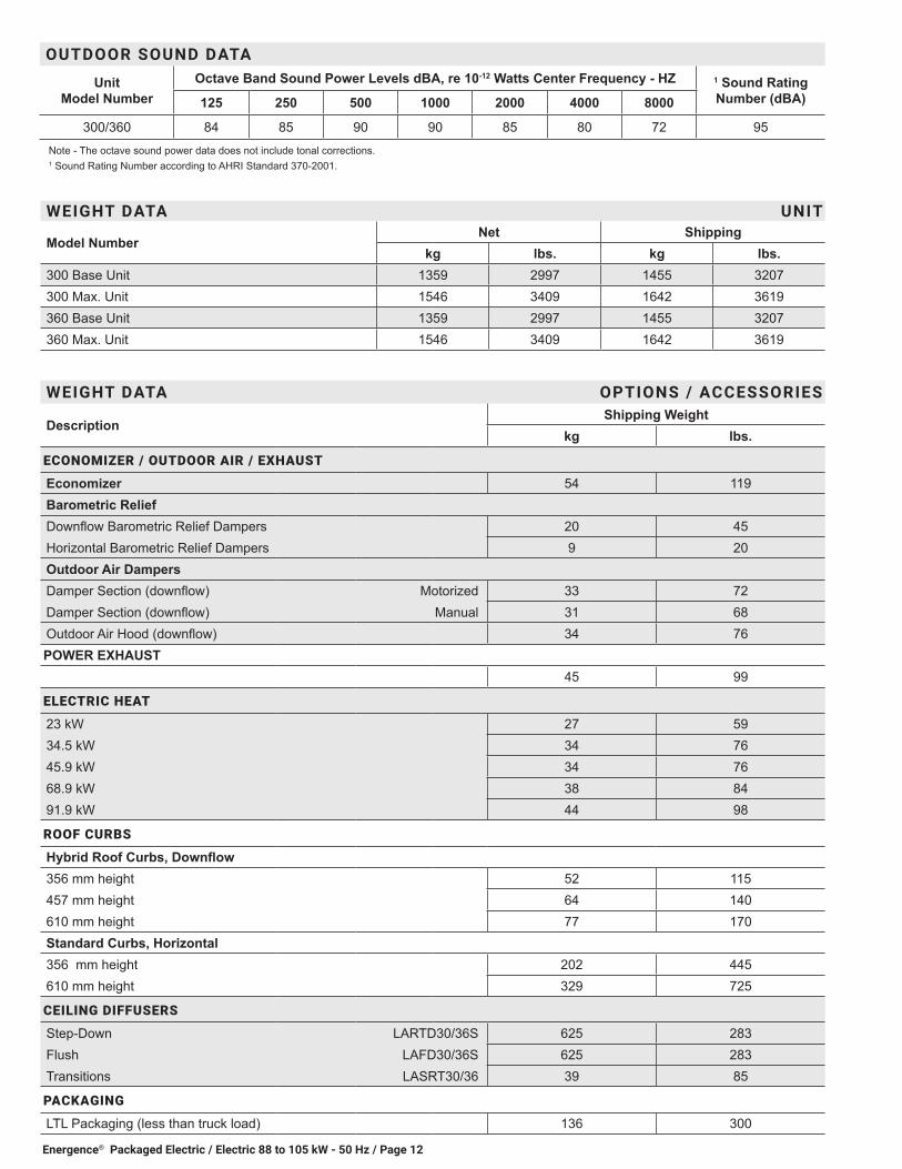
WEIGHT DATA UNIT
Model NumberNet Shipping
kg lbs. kg lbs.300 Base Unit 1359 2997 1455 3207300 Max. Unit 1546 3409 1642 3619360 Base Unit 1359 2997 1455 3207360 Max. Unit 1546 3409 1642 3619
WEIGHT DATA OPTIONS / ACCESSORIES
DescriptionShipping Weight
kg lbs.
ECONOMIZER / OUTDOOR AIR / EXHAUST
Economizer 54 119Barometric ReliefDownflow Barometric Relief Dampers 20 45Horizontal Barometric Relief Dampers 9 20Outdoor Air DampersDamper Section (downflow) Motorized 33 72Damper Section (downflow) Manual 31 68Outdoor Air Hood (downflow) 34 76POWER EXHAUST
45 99
ELECTRIC HEAT
23 kW 27 5934.5 kW 34 7645.9 kW 34 7668.9 kW 38 8491.9 kW 44 98
ROOF CURBS
Hybrid Roof Curbs, Downflow356 mm height 52 115457 mm height 64 140610 mm height 77 170Standard Curbs, Horizontal356 mm height 202 445610 mm height 329 725
CEILING DIFFUSERS
Step-Down LARTD30/36S 625 283Flush LAFD30/36S 625 283Transitions LASRT30/36 39 85
PACKAGING
LTL Packaging (less than truck load) 136 300
OUTDOOR SOUND DATA
Unit Model Number
Octave Band Sound Power Levels dBA, re 10-12 Watts Center Frequency - HZ 1 Sound Rating Number (dBA)125 250 500 1000 2000 4000 8000
300/360 84 85 90 90 85 80 72 95Note - The octave sound power data does not include tonal corrections.1 Sound Rating Number according to AHRI Standard 370-2001.

Energence® Packaged Electric / Electric 88 to 105 kW - 50 Hz / Page 13
OPTIONS / ACCESSORIES
Item Description Model Number
Catalog Number
Unit Model No300 360
INDOOR AIR QUALITY
Air FiltersHealthy Climate High Efficiency Air Filters 508 x 508 x 51 mm - order 12 per unit
MERV 8 - C1FLTR15D-1- 54W21 OX OX
MERV 13 - C1FLTR40D-1- 52W39 OX OX
Replaceable Media Filter with Metal Mesh Frame (includes Non-Pleated Filter Media) 508 x 508 x 51 mm - order 12 per unit
C1FLTR30D-1- 44N60 X X
Indoor Air Quality (CO2) SensorsSensor - Wall-mount, off-white plastic cover with LCD display C0SNSR50AE1L 77N39 X X
Sensor - Wall-mount, off-white plastic cover, no display C0SNSR52AE1L 87N53 X X
Sensor - Black plastic case with LCD display, rated for plenum mounting C0SNSR51AE1L 87N52 X X
Sensor - Wall-mount, black plastic case, no display, rated for plenum mounting
C0MISC19AE1 87N54 X X
CO2 Sensor Duct Mounting Kit - for downflow applications C0MISC19AE1- 85L43 X X
Aspiration Box - for duct mounting non-plenum rated CO2 sensors (87N53 or 77N39)
C0MISC16AE1- 90N43 X X
ELECTRICAL
Voltage 50 hz with neutral 380/420V - 3 phase Factory O O
ELECTRIC HEAT
23 kW 380/420V-3ph - C1EH0230C21M 67W98 OX OX
34.5 kW 380/420V-3ph - C1EH0345C21M 68W00 OX OX
45.9 kW 380/420V-3ph - C1EH0459C21M 68W02 OX OX
68.9 kW 380/420V-3ph - C1EH0689C-1M 68W03 OX OX
91.9 kW 380/420V-3ph - E1EH0900D-1M 74W01 OX OX
ECONOMIZER
High Performance EconomizerHigh Performance Economizer Downflow or Horizontal Applications - Includes Outdoor Air Hood. Order Downflow or Horizontal Barometric Relief Dampers separately.
E1ECON17D-2 18X87 OX OX
Economizer ControlsDifferential Enthalpy Order 2 - C1SNSR64FF1 21Z09 OX OX
Sensible Control Sensor is Furnished Factory O O
Single Enthalpy C1SNSR64FF1 21Z09 OX OX
Global, Enthalpy Sensor Field Provided Factory O O
Differential Sensible Sensor is Furnished Factory O O
Barometric Relief Dampers With Exhaust Hood Downflow Barometric Relief Dampers E1DAMP60D-1 76W17 OX OX
Horizontal Barometric Relief Dampers LAGEDH30/36 33K78 OX OX
OUTDOOR AIR
Outdoor Air Dampers With Outdoor Air HoodMotorized E1DAMP25D-2- 18X89 OX OX
Manual E1DAMP15D-2- 18X88 OX OXNOTE - Catalog and model numbers shown are for ordering field installed accessories.OX - Configure To Order (Factory Installed) or Field InstalledO = Configure To Order (Factory Installed)X = Field Installed

Energence® Packaged Electric / Electric 88 to 105 kW - 50 Hz / Page 14
OPTIONS / ACCESSORIES
Item Description Model Number
Catalog Number
Unit Model No300 360
POWER EXHAUST
Standard Static 380/420V - E1PWRE40D-1M 74W24 OX OX
ROOF CURBS
Hybrid Roof Curbs, Downflow
356 mm height C1CURB71D-1 11F62 X X
457 mm height C1CURB72D-1 11F63 X X
610 mm height C1CURB73D-1 11F64 X X
Standard Roof Curbs, Horizontal - Requires Horizontal Air Panel Kit
762 mm height - slab applications C1CURB15C-1 11T90 X X
1041 mm height - rooftop applications C1CURB17C-1 11T97 X X
Horizontal Return Air Panel Kit (Required) 38K48 X X
Insulation Kit For Standard Horizontal Curbs
for C1CURB15C-1 73K33 X X
for C1CURB17C-1 73K35 X X
CEILING DIFFUSERS
Step-Down - Order one LARTD30/36S 45K74 X X
Flush - Order one LAFD30/36S 45K75 X X
Transitions (Supply and Return) - Order one LASRT30/36 33K80 X XNOTE - Catalog and model numbers shown are for ordering field installed accessories.OX - Configure To Order (Factory Installed) or Field InstalledO = Configure To Order (Factory Installed)X = Field Installed
Energence® Packaged Electric / Electric 88 to 105 kW - 50 Hz / Page 15
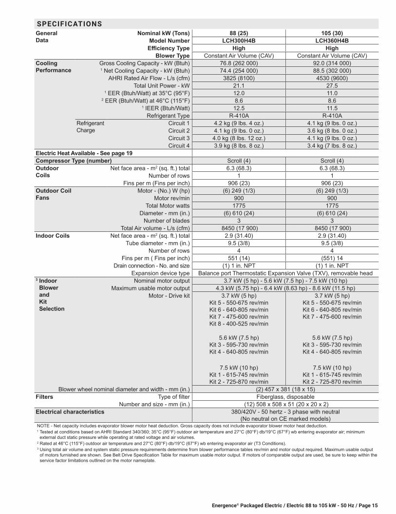
SPECIFICATIONSGeneral Data
Nominal kW (Tons) 88 (25) 105 (30)Model Number LCH300H4B LCH360H4B
Efficiency Type High HighBlower Type Constant Air Volume (CAV) Constant Air Volume (CAV)
Cooling Performance
Gross Cooling Capacity - kW (Btuh) 76.8 (262 000) 92.0 (314 000)1 Net Cooling Capacity - kW (Btuh) 74.4 (254 000) 88.5 (302 000)
AHRI Rated Air Flow - L/s (cfm) 3825 (8100) 4530 (9600)Total Unit Power - kW 21.1 27.5
1 EER (Btuh/Watt) at 35°C (95°F) 12.0 11.02 EER (Btuh/Watt) at 46°C (115°F) 8.6 8.6
1 IEER (Btuh/Watt) 12.5 11.5Refrigerant Type R-410A R-410A
Refrigerant Charge
Circuit 1 4.2 kg (9 lbs. 4 oz.) 4.1 kg (9 lbs. 0 oz.)Circuit 2 4.1 kg (9 lbs. 0 oz.) 3.6 kg (8 lbs. 0 oz.)Circuit 3 4.0 kg (8 lbs. 12 oz.) 4.1 kg (9 lbs. 0 oz.)Circuit 4 3.9 kg (8 lbs. 8 oz.) 3.4 kg (7 lbs. 8 oz.)
Electric Heat Available - See page 19 Compressor Type (number) Scroll (4) Scroll (4)Outdoor Coils
Net face area - m2 (sq. ft.) total 6.3 (68.3) 6.3 (68.3)Number of rows 1 1
Fins per m (Fins per inch) 906 (23) 906 (23)Outdoor Coil Fans
Motor - (No.) W (hp) (6) 249 (1/3) (6) 249 (1/3)Motor rev/min 900 900
Total Motor watts 1775 1775Diameter - mm (in.) (6) 610 (24) (6) 610 (24)
Number of blades 3 3Total Air volume - L/s (cfm) 8450 (17 900) 8450 (17 900)
Indoor Coils Net face area - m2 (sq. ft.) total 2.9 (31.40) 2.9 (31.40)Tube diameter - mm (in.) 9.5 (3/8) 9.5 (3/8)
Number of rows 4 4Fins per m ( Fins per inch) 551 (14) (551) 14
Drain connection - No. and size (1) 1 in. NPT (1) 1 in. NPTExpansion device type Balance port Thermostatic Expansion Valve (TXV), removable head
3 Indoor Blower and Kit Selection
Nominal motor output 3.7 kW (5 hp) - 5.6 kW (7.5 hp) - 7.5 kW (10 hp)Maximum usable motor output 4.3 kW (5.75 hp) - 6.4 kW (8.63 hp) - 8.6 kW (11.5 hp)
Motor - Drive kit 3.7 kW (5 hp) Kit 5 - 550-675 rev/min Kit 6 - 640-805 rev/min Kit 7 - 475-600 rev/min Kit 8 - 400-525 rev/min
5.6 kW (7.5 hp)
Kit 3 - 595-730 rev/min Kit 4 - 640-805 rev/min
7.5 kW (10 hp)
Kit 1 - 615-745 rev/min Kit 2 - 725-870 rev/min
3.7 kW (5 hp) Kit 5 - 550-675 rev/min Kit 6 - 640-805 rev/min Kit 7 - 475-600 rev/min
5.6 kW (7.5 hp) Kit 3 - 595-730 rev/min Kit 4 - 640-805 rev/min
7.5 kW (10 hp)
Kit 1 - 615-745 rev/min Kit 2 - 725-870 rev/min
Blower wheel nominal diameter and width - mm (in.) (2) 457 x 381 (18 x 15)Filters Type of filter Fiberglass, disposable
Number and size - mm (in.) (12) 508 x 508 x 51 (20 x 20 x 2)Electrical characteristics 380/420V - 50 hertz - 3 phase with neutral
(No neutral on CE marked models)NOTE - Net capacity includes evaporator blower motor heat deduction. Gross capacity does not include evaporator blower motor heat deduction.1 Tested at conditions based on AHRI Standard 340/360; 35°C (95°F) outdoor air temperature and 27°C (80°F) db/19°C (67°F) wb entering evaporator air; minimum
external duct static pressure while operating at rated voltage and air volumes.2 Rated at 46°C (115°F) outdoor air temperature and 27°C (80°F) db/19°C (67°F) wb entering evaporator air (T3 Conditions). 3 Using total air volume and system static pressure requirements determine from blower performance tables rev/min and motor output required. Maximum usable output
of motors furnished are shown. See Belt Drive Specification Table for maximum usable motor output. If motors of comparable output are used, be sure to keep within the service factor limitations outlined on the motor nameplate.
Energence® Packaged Electric / Electric 88 to 105 kW - 50 Hz / Page 16
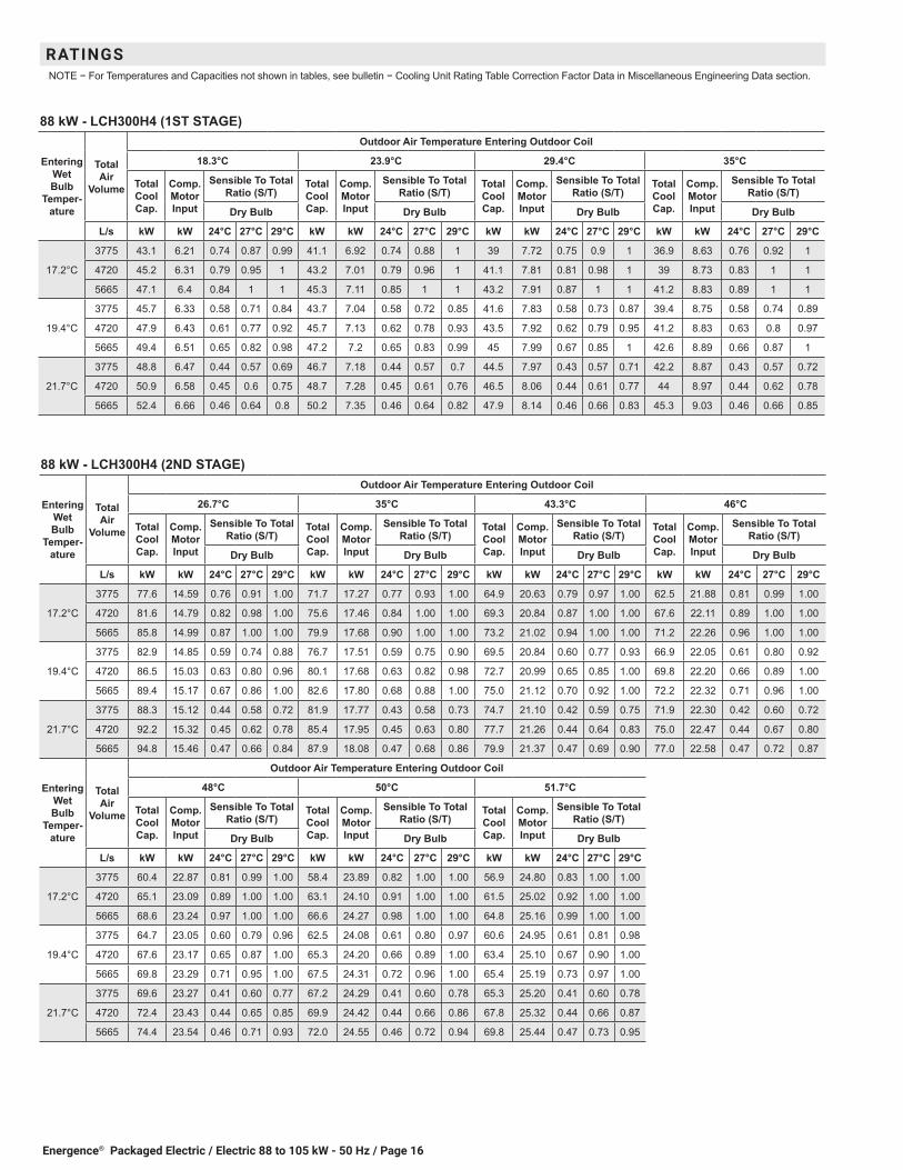
RATINGSNOTE − For Temperatures and Capacities not shown in tables, see bulletin − Cooling Unit Rating Table Correction Factor Data in Miscellaneous Engineering Data section.
88 kW - LCH300H4 (1ST STAGE)
Entering Wet Bulb
Temper-ature
Total Air
Volume
Outdoor Air Temperature Entering Outdoor Coil
18.3°C 23.9°C 29.4°C 35°C
Total Cool Cap.
Comp. Motor Input
Sensible To Total Ratio (S/T)
Total Cool Cap.
Comp. Motor Input
Sensible To Total Ratio (S/T)
Total Cool Cap.
Comp. Motor Input
Sensible To Total Ratio (S/T)
Total Cool Cap.
Comp. Motor Input
Sensible To Total Ratio (S/T)
Dry Bulb Dry Bulb Dry Bulb Dry Bulb
L/s kW kW 24°C 27°C 29°C kW kW 24°C 27°C 29°C kW kW 24°C 27°C 29°C kW kW 24°C 27°C 29°C
17.2°C
3775 43.1 6.21 0.74 0.87 0.99 41.1 6.92 0.74 0.88 1 39 7.72 0.75 0.9 1 36.9 8.63 0.76 0.92 1
4720 45.2 6.31 0.79 0.95 1 43.2 7.01 0.79 0.96 1 41.1 7.81 0.81 0.98 1 39 8.73 0.83 1 1
5665 47.1 6.4 0.84 1 1 45.3 7.11 0.85 1 1 43.2 7.91 0.87 1 1 41.2 8.83 0.89 1 1
19.4°C
3775 45.7 6.33 0.58 0.71 0.84 43.7 7.04 0.58 0.72 0.85 41.6 7.83 0.58 0.73 0.87 39.4 8.75 0.58 0.74 0.89
4720 47.9 6.43 0.61 0.77 0.92 45.7 7.13 0.62 0.78 0.93 43.5 7.92 0.62 0.79 0.95 41.2 8.83 0.63 0.8 0.97
5665 49.4 6.51 0.65 0.82 0.98 47.2 7.2 0.65 0.83 0.99 45 7.99 0.67 0.85 1 42.6 8.89 0.66 0.87 1
21.7°C
3775 48.8 6.47 0.44 0.57 0.69 46.7 7.18 0.44 0.57 0.7 44.5 7.97 0.43 0.57 0.71 42.2 8.87 0.43 0.57 0.72
4720 50.9 6.58 0.45 0.6 0.75 48.7 7.28 0.45 0.61 0.76 46.5 8.06 0.44 0.61 0.77 44 8.97 0.44 0.62 0.78
5665 52.4 6.66 0.46 0.64 0.8 50.2 7.35 0.46 0.64 0.82 47.9 8.14 0.46 0.66 0.83 45.3 9.03 0.46 0.66 0.85
88 kW - LCH300H4 (2ND STAGE)
Entering Wet Bulb
Temper-ature
Total Air
Volume
Outdoor Air Temperature Entering Outdoor Coil
26.7°C 35°C 43.3°C 46°C
Total Cool Cap.
Comp. Motor Input
Sensible To Total Ratio (S/T)
Total Cool Cap.
Comp. Motor Input
Sensible To Total Ratio (S/T)
Total Cool Cap.
Comp. Motor Input
Sensible To Total Ratio (S/T)
Total Cool Cap.
Comp. Motor Input
Sensible To Total Ratio (S/T)
Dry Bulb Dry Bulb Dry Bulb Dry Bulb
L/s kW kW 24°C 27°C 29°C kW kW 24°C 27°C 29°C kW kW 24°C 27°C 29°C kW kW 24°C 27°C 29°C
17.2°C
3775 77.6 14.59 0.76 0.91 1.00 71.7 17.27 0.77 0.93 1.00 64.9 20.63 0.79 0.97 1.00 62.5 21.88 0.81 0.99 1.00
4720 81.6 14.79 0.82 0.98 1.00 75.6 17.46 0.84 1.00 1.00 69.3 20.84 0.87 1.00 1.00 67.6 22.11 0.89 1.00 1.00
5665 85.8 14.99 0.87 1.00 1.00 79.9 17.68 0.90 1.00 1.00 73.2 21.02 0.94 1.00 1.00 71.2 22.26 0.96 1.00 1.00
19.4°C
3775 82.9 14.85 0.59 0.74 0.88 76.7 17.51 0.59 0.75 0.90 69.5 20.84 0.60 0.77 0.93 66.9 22.05 0.61 0.80 0.92
4720 86.5 15.03 0.63 0.80 0.96 80.1 17.68 0.63 0.82 0.98 72.7 20.99 0.65 0.85 1.00 69.8 22.20 0.66 0.89 1.00
5665 89.4 15.17 0.67 0.86 1.00 82.6 17.80 0.68 0.88 1.00 75.0 21.12 0.70 0.92 1.00 72.2 22.32 0.71 0.96 1.00
21.7°C
3775 88.3 15.12 0.44 0.58 0.72 81.9 17.77 0.43 0.58 0.73 74.7 21.10 0.42 0.59 0.75 71.9 22.30 0.42 0.60 0.72
4720 92.2 15.32 0.45 0.62 0.78 85.4 17.95 0.45 0.63 0.80 77.7 21.26 0.44 0.64 0.83 75.0 22.47 0.44 0.67 0.80
5665 94.8 15.46 0.47 0.66 0.84 87.9 18.08 0.47 0.68 0.86 79.9 21.37 0.47 0.69 0.90 77.0 22.58 0.47 0.72 0.87
Entering Wet Bulb
Temper-ature
Total Air
Volume
Outdoor Air Temperature Entering Outdoor Coil
48°C 50°C 51.7°C
Total Cool Cap.
Comp. Motor Input
Sensible To Total Ratio (S/T)
Total Cool Cap.
Comp. Motor Input
Sensible To Total Ratio (S/T)
Total Cool Cap.
Comp. Motor Input
Sensible To Total Ratio (S/T)
Dry Bulb Dry Bulb Dry Bulb
L/s kW kW 24°C 27°C 29°C kW kW 24°C 27°C 29°C kW kW 24°C 27°C 29°C
17.2°C
3775 60.4 22.87 0.81 0.99 1.00 58.4 23.89 0.82 1.00 1.00 56.9 24.80 0.83 1.00 1.00
4720 65.1 23.09 0.89 1.00 1.00 63.1 24.10 0.91 1.00 1.00 61.5 25.02 0.92 1.00 1.00
5665 68.6 23.24 0.97 1.00 1.00 66.6 24.27 0.98 1.00 1.00 64.8 25.16 0.99 1.00 1.00
19.4°C
3775 64.7 23.05 0.60 0.79 0.96 62.5 24.08 0.61 0.80 0.97 60.6 24.95 0.61 0.81 0.98
4720 67.6 23.17 0.65 0.87 1.00 65.3 24.20 0.66 0.89 1.00 63.4 25.10 0.67 0.90 1.00
5665 69.8 23.29 0.71 0.95 1.00 67.5 24.31 0.72 0.96 1.00 65.4 25.19 0.73 0.97 1.00
21.7°C
3775 69.6 23.27 0.41 0.60 0.77 67.2 24.29 0.41 0.60 0.78 65.3 25.20 0.41 0.60 0.78
4720 72.4 23.43 0.44 0.65 0.85 69.9 24.42 0.44 0.66 0.86 67.8 25.32 0.44 0.66 0.87
5665 74.4 23.54 0.46 0.71 0.93 72.0 24.55 0.46 0.72 0.94 69.8 25.44 0.47 0.73 0.95
Energence® Packaged Electric / Electric 88 to 105 kW - 50 Hz / Page 17
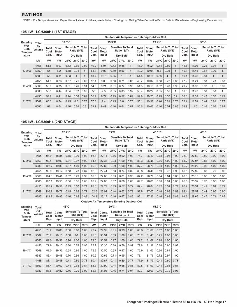
105 kW - LCH360H4 (1ST STAGE)
Entering Wet Bulb
Temper-ature
Total Air
Volume
Outdoor Air Temperature Entering Outdoor Coil
18.3°C 23.9°C 29.4°C 35°C
Total Cool Cap.
Comp. Motor Input
Sensible To Total Ratio (S/T)
Total Cool Cap.
Comp. Motor Input
Sensible To Total Ratio (S/T)
Total Cool Cap.
Comp. Motor Input
Sensible To Total Ratio (S/T)
Total Cool Cap.
Comp. Motor Input
Sensible To Total Ratio (S/T)
Dry Bulb Dry Bulb Dry Bulb Dry Bulb
L/s kW kW 24°C 27°C 29°C kW kW 24°C 27°C 29°C kW kW 24°C 27°C 29°C kW kW 24°C 27°C 29°C
17.2°C
4455 51.5 8.07 0.73 0.86 0.99 49.2 8.94 0.73 0.88 1 46.9 9.92 0.74 0.89 1 44.6 11.06 0.75 0.91 1
5569 54 8.2 0.78 0.94 1 51.5 9.06 0.79 0.96 1 49.2 10.04 0.8 0.98 1 46.8 11.18 0.81 0.99 1
6683 56 8.31 0.83 1 1 53.7 9.18 0.85 1 1 51.5 10.16 0.86 1 1 49.1 11.32 0.88 1 1
19.4°C
4455 54.5 8.23 0.57 0.71 0.83 52.1 9.09 0.58 0.71 0.85 49.7 10.07 0.58 0.72 0.86 47.2 11.21 0.58 0.73 0.88
5569 56.8 8.35 0.61 0.76 0.91 54.3 9.21 0.61 0.77 0.93 51.8 10.18 0.62 0.78 0.95 49.2 11.32 0.62 0.8 0.96
6683 58.5 8.44 0.64 0.82 0.98 56 9.3 0.65 0.83 0.99 53.4 10.29 0.65 0.85 1 50.8 11.42 0.66 0.86 1
21.7°C
4455 57.9 8.41 0.44 0.56 0.69 55.4 9.27 0.43 0.57 0.69 52.9 10.25 0.43 0.57 0.7 50.3 11.39 0.42 0.57 0.71
5569 60.3 8.54 0.45 0.6 0.75 57.6 9.4 0.45 0.6 0.75 55.1 10.38 0.44 0.61 0.76 52.4 11.51 0.44 0.61 0.77
6683 62 8.64 0.46 0.64 0.8 59.2 9.49 0.46 0.64 0.81 56.6 10.46 0.46 0.64 0.83 53.9 11.6 0.46 0.66 0.84
RATINGSNOTE − For Temperatures and Capacities not shown in tables, see bulletin − Cooling Unit Rating Table Correction Factor Data in Miscellaneous Engineering Data section.
105 kW - LCH360H4 (2ND STAGE)
Entering Wet Bulb
Temper-ature
Total Air
Volume
Outdoor Air Temperature Entering Outdoor Coil
26.7°C 35°C 43.3°C 46°C
Total Cool Cap.
Comp. Motor Input
Sensible To Total Ratio (S/T)
Total Cool Cap.
Comp. Motor Input
Sensible To Total Ratio (S/T)
Total Cool Cap.
Comp. Motor Input
Sensible To Total Ratio (S/T)
Total Cool Cap.
Comp. Motor Input
Sensible To Total Ratio (S/T)
Dry Bulb Dry Bulb Dry Bulb Dry Bulb
L/s kW kW 24°C 27°C 29°C kW kW 24°C 27°C 29°C kW kW 24°C 27°C 29°C kW kW 24°C 27°C 29°C
17.2°C
4455 94.0 18.85 0.75 0.90 1.00 86.8 22.11 0.76 0.92 1.00 78.7 26.17 0.78 0.96 1.00 75.9 27.62 0.80 0.99 1.00
5569 98.4 19.09 0.81 0.97 1.00 91.1 22.35 0.83 1.00 1.00 83.3 26.45 0.86 1.00 1.00 81.2 27.97 0.88 1.00 1.00
6683 102.7 19.33 0.87 1.00 1.00 95.6 22.63 0.89 1.00 1.00 87.7 26.73 0.93 1.00 1.00 85.2 28.22 0.96 1.00 1.00
19.4°C
4455 99.9 19.17 0.58 0.73 0.87 92.3 22.44 0.58 0.74 0.89 83.8 26.48 0.59 0.76 0.93 80.5 27.92 0.60 0.79 0.92
5569 104.0 19.41 0.62 0.79 0.95 96.0 22.66 0.63 0.81 0.98 87.2 26.70 0.64 0.84 1.00 83.9 28.15 0.66 0.88 1.00
6683 107.1 19.58 0.66 0.85 1.00 98.9 22.83 0.67 0.88 1.00 89.7 26.85 0.68 0.91 1.00 86.5 28.32 0.70 0.96 1.00
21.7°C
4455 105.9 19.51 0.43 0.57 0.71 98.0 22.77 0.43 0.57 0.72 89.4 26.84 0.42 0.59 0.74 86.2 28.31 0.42 0.61 0.72
5569 110.2 19.77 0.45 0.62 0.77 102.0 23.01 0.44 0.62 0.79 92.8 27.05 0.44 0.63 0.82 89.4 28.51 0.44 0.66 0.80
6683 113.2 19.95 0.46 0.65 0.83 104.8 23.19 0.46 0.67 0.86 95.1 27.22 0.46 0.68 0.89 91.6 28.65 0.47 0.71 0.87
Entering Wet Bulb
Temper-ature
Total Air
Volume
Outdoor Air Temperature Entering Outdoor Coil
48°C 50°C 51.7°C
Total Cool Cap.
Comp. Motor Input
Sensible To Total Ratio (S/T)
Total Cool Cap.
Comp. Motor Input
Sensible To Total Ratio (S/T)
Total Cool Cap.
Comp. Motor Input
Sensible To Total Ratio (S/T)
Dry Bulb Dry Bulb Dry Bulb
L/s kW kW 24°C 27°C 29°C kW kW 24°C 27°C 29°C kW kW 24°C 27°C 29°C
17.2°C
4455 73.2 28.80 0.80 0.98 1.00 70.7 29.99 0.81 0.99 1.00 68.6 31.08 0.82 1.00 1.00
5569 78.2 29.13 0.88 0\1 1.00 75.8 30.34 0.89 1.00 1.00 73.7 31.43 0.91 1.00 1.00
6683 82.0 29.38 0.96 1.00 1.00 79.5 30.59 0.97 1.00 1.00 77.2 31.69 0.98 1.00 1.00
19.4°C
4455 77.9 29.10 0.60 0.78 0.95 75.2 30.30 0.60 0.79 0.97 72.8 31.38 0.60 0.80 0.98
5569 81.0 29.32 0.65 0.86 1.00 78.2 30.50 0.65 0.87 1.00 75.9 31.60 0.66 0.89 1.00
6683 83.4 29.48 0.70 0.94 1.00 80.5 30.69 0.71 0.95 1.00 78.1 31.76 0.72 0.97 1.00
21.7°C
4455 83.1 29.45 0.41 0.59 0.76 80.4 30.67 0.41 0.59 0.77 77.9 31.73 0.41 0.60 0.78
5569 86.4 29.69 0.44 0.65 0.84 83.3 30.90 0.44 0.65 0.85 80.5 31.93 0.44 0.66 0.87
6683 88.5 29.82 0.46 0.70 0.92 85.5 31.03 0.46 0.71 0.94 82.7 32.09 0.46 0.72 0.95
Energence® Packaged Electric / Electric 88 to 105 kW - 50 Hz / Page 18
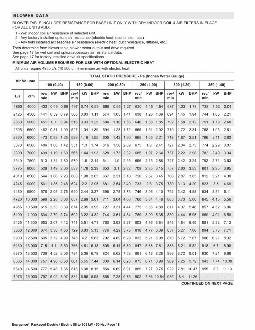
BLOWER DATABLOWER TABLE INCLUDES RESISTANCE FOR BASE UNIT ONLY WITH DRY INDOOR COIL & AIR FILTERS IN PLACE FOR ALL UNITS ADD:
1 - Wet indoor coil air resistance of selected unit. 2 - Any factory installed options air resistance (electric heat, economizer, etc.) 3 - Any field installed accessories air resistance (electric heat, duct resistance, diffuser, etc.)
Then determine from blower table blower motor output and drive required. See page 17 for wet coil and option/accessory air resistance data. See page 17 for factory installed drive kit specifications.MINIMUM AIR VOLUME REQUIRED FOR USE WITH OPTIONAL ELECTRIC HEAT
All units require 4955 L/s (10 500 cfm) minimum air with electric heat.
Air VolumeTOTAL STATIC PRESSURE - Pa (Inches Water Gauge)
100 (0.40) 150 (0.60) 200 (0.80) 250 (1.00) 300 (1.20) 350 (1.40)
L/s cfmrev/min
kW BHP rev/min
kW BHP rev/min
kW BHP rev/min
kW BHP rev/min
kW BHP rev/min
kW BHP
1890 4000 433 0.49 0.66 497 0.74 0.99 565 0.95 1.27 630 1.15 1.54 687 1.33 1.78 738 1.52 2.04
2125 4500 441 0.59 0.79 506 0.83 1.11 574 1.05 1.41 638 1.26 1.69 694 1.45 1.94 744 1.65 2.21
2360 5000 451 0.7 0.94 516 0.93 1.25 584 1.16 1.55 646 1.38 1.85 702 1.58 2.12 751 1.79 2.40
2595 5500 462 0.81 1.09 527 1.04 1.39 594 1.28 1.72 655 1.51 2.02 710 1.72 2.31 758 1.95 2.61
2830 6000 473 0.93 1.25 539 1.16 1.55 605 1.42 1.90 665 1.65 2.21 718 1.87 2.51 766 2.11 2.83
3070 6500 486 1.06 1.42 551 1.3 1.74 616 1.56 2.09 675 1.8 2.41 727 2.04 2.73 774 2.29 3.07
3300 7000 499 1.19 1.60 565 1.44 1.93 628 1.73 2.32 685 1.97 2.64 737 2.22 2.98 782 2.49 3.34
3540 7500 513 1.34 1.80 579 1.6 2.14 641 1.9 2.55 696 2.15 2.88 747 2.42 3.24 792 2.71 3.63
3775 8000 528 1.49 2.00 593 1.78 2.39 653 2.1 2.82 708 2.35 3.15 757 2.63 3.53 801 2.95 3.95
4010 8500 544 1.66 2.23 608 1.98 2.65 667 2.31 3.10 720 2.57 3.45 768 2.87 3.85 812 3.21 4.30
4245 9000 561 1.85 2.48 624 2.2 2.95 681 2.54 3.40 733 2.8 3.75 780 3.13 4.20 823 3.5 4.69
4480 9500 578 2.05 2.75 640 2.44 3.27 696 2.78 3.73 746 3.06 4.10 792 3.42 4.58 834 3.81 5.11
4720 10 000 596 2.28 3.06 657 2.69 3.61 711 3.04 4.08 760 3.34 4.48 805 3.73 5.00 845 4.15 5.56
4955 10 500 615 2.53 3.39 674 2.95 3.95 727 3.31 4.44 775 3.65 4.89 817 4.07 5.46 857 4.52 6.06
5190 11 000 634 2.79 3.74 692 3.22 4.32 744 3.61 4.84 789 3.99 5.35 830 4.44 5.95 869 4.91 6.58
5425 11 500 653 3.07 4.12 711 3.51 4.71 760 3.93 5.27 803 4.36 5.84 843 4.84 6.49 881 5.32 7.13
5660 12 000 674 3.38 4.53 729 3.83 5.13 776 4.29 5.75 818 4.77 6.39 857 5.27 7.06 894 5.75 7.71
5900 12 500 695 3.72 4.99 748 4.2 5.63 792 4.69 6.29 832 5.21 6.98 870 5.72 7.67 906 6.21 8.32
6130 13 000 715 4.1 5.50 766 4.61 6.18 808 5.14 6.89 847 5.68 7.61 883 6.21 8.32 918 6.7 8.98
6370 13 500 736 4.52 6.06 784 5.06 6.78 824 5.62 7.53 861 6.18 8.28 896 6.72 9.01 930 7.21 9.66
6605 14 000 757 4.98 6.68 801 5.55 7.44 839 6.14 8.23 875 6.71 8.99 909 7.25 9.72 943 7.74 10.38
6840 14 500 777 5.48 7.35 818 6.08 8.15 854 6.69 8.97 889 7.27 9.75 922 7.81 10.47 955 8.3 11.13
7075 15 000 797 6.02 8.07 834 6.66 8.93 868 7.28 9.76 902 7.86 10.54 935 8.4 11.26 - - - - - - - - -
CONTINUED ON NEXT PAGE

Energence® Packaged Electric / Electric 88 to 105 kW - 50 Hz / Page 19
BLOWER DATABLOWER TABLE INCLUDES RESISTANCE FOR BASE UNIT ONLY WITH DRY INDOOR COIL & AIR FILTERS IN PLACE FOR ALL UNITS ADD:
1 - Wet indoor coil air resistance of selected unit. 2 - Any factory installed options air resistance (electric heat, economizer, etc.) 3 - Any field installed accessories air resistance (electric heat, duct resistance, diffuser, etc.)
Then determine from blower table blower motor output and drive required. See page 17 for wet coil and option/accessory air resistance data. See page 17 for factory installed drive kit specifications.MINIMUM AIR VOLUME REQUIRED FOR USE WITH OPTIONAL ELECTRIC HEAT
All units require 4955 L/s (10 500 cfm) minimum air with electric heat.
Air VolumeTOTAL STATIC PRESSURE - Pa (Inches Water Gauge)
400 (1.60) 450 (1.80) 500 (2.00) 550 (2.20) 600 (2.40) 650 (2.60)
L/s cfmrev/min
kW BHP rev/min
kW BHP rev/min
kW BHP rev/min
kW BHP rev/min
kW BHP rev/min
kW BHP
1890 4000 784 1.72 2.31 824 1.91 2.56 861 2.1 2.82 897 2.31 3.10 932 2.54 3.40 - - - - - - - - -
2125 4500 790 1.86 2.49 831 2.07 2.77 868 2.28 3.06 903 2.5 3.35 938 2.73 3.66 974 2.99 4.01
2360 5000 796 2.01 2.69 837 2.24 3.00 874 2.46 3.30 909 2.69 3.61 944 2.94 3.94 980 3.21 4.30
2595 5500 802 2.18 2.92 843 2.42 3.24 880 2.66 3.57 916 2.9 3.89 951 3.15 4.22 987 3.43 4.60
2830 6000 809 2.36 3.16 850 2.62 3.51 887 2.87 3.85 922 3.12 4.18 957 3.38 4.53 994 3.66 4.91
3070 6500 817 2.56 3.43 857 2.83 3.79 894 3.1 4.16 929 3.35 4.49 964 3.62 4.85 1001 3.91 5.24
3300 7000 825 2.78 3.73 864 3.07 4.12 901 3.34 4.48 937 3.6 4.83 971 3.87 5.19 1008 4.17 5.59
3540 7500 833 3.02 4.05 872 3.32 4.45 909 3.61 4.84 945 3.88 5.20 979 4.15 5.56 1016 4.45 5.97
3775 8000 843 3.28 4.40 881 3.6 4.83 918 3.89 5.21 953 4.17 5.59 988 4.45 5.97 1025 4.75 6.37
4010 8500 852 3.56 4.77 890 3.89 5.21 927 4.2 5.63 962 4.49 6.02 997 4.77 6.39 1034 5.08 6.81
4245 9000 862 3.87 5.19 900 4.22 5.66 936 4.53 6.07 972 4.82 6.46 1007 5.11 6.85 1044 5.43 7.28
4480 9500 873 4.21 5.64 910 4.56 6.11 946 4.88 6.54 982 5.17 6.93 1018 5.47 7.33 1055 5.8 7.77
4720 10 000 884 4.57 6.13 921 4.93 6.61 957 5.24 7.02 992 5.54 7.43 1028 5.86 7.86 1066 6.2 8.31
4955 10 500 895 4.94 6.62 932 5.31 7.12 967 5.63 7.55 1003 5.93 7.95 1039 6.27 8.40 1077 6.63 8.89
5190 11 000 907 5.34 7.16 943 5.71 7.65 978 6.03 8.08 1013 6.35 8.51 1050 6.7 8.98 1089 7.08 9.49
5425 11 500 918 5.75 7.71 954 6.13 8.22 989 6.46 8.66 1025 6.78 9.09 1062 7.15 9.58 1101 7.55 10.12
5660 12 000 930 6.19 8.30 965 6.57 8.81 1000 6.9 9.25 1036 7.24 9.71 1073 7.62 10.21 1112 8.03 10.76
5900 12 500 941 6.65 8.91 976 7.03 9.42 1011 7.37 9.88 1048 7.72 10.35 1085 8.1 10.86 1124 8.52 11.42
6130 13 000 953 7.13 9.56 988 7.51 10.07 1023 7.85 10.52 1059 8.21 11.01 - - - - - - - - - - - - - - - - - -
6370 13 500 965 7.64 10.24 1000 8.01 10.74 1035 8.35 11.19 - - - - - - - - - - - - - - - - - - - - - - - - - - -
6605 14 000 977 8.16 10.94 1012 8.53 11.43 - - - - - - - - - - - - - - - - - - - - - - - - - - - - - - - - - - - -

Energence® Packaged Electric / Electric 88 to 105 kW - 50 Hz / Page 20
FACTORY INSTALLED OPTIONS/FIELD INSTALLED ACCESSORY AIR RESISTANCEAir
Volume Wet Indoor Coil Electric Heat Economizer
Filters Horizontal Roof CurbMERV 8 MERV 13
L/s cfm Pa in. w.g. Pa in. w.g. Pa in. w.g. Pa in. w.g. Pa in. w.g. Pa in. w.g.1890 4000 10 0.04 2 0.01 0 0.00 0 0.00 0 0.00 10 0.04
2125 4500 10 0.04 2 0.01 0 0.00 0 0.00 0 0.00 12 0.05
2360 5000 12 0.05 2 0.01 0 0.00 0 0.00 0 0.00 15 0.06
2595 5500 15 0.06 5 0.02 2 0.01 0 0.00 2 0.01 17 0.07
2830 6000 17 0.07 5 0.02 2 0.01 0 0.00 5 0.02 20 0.08
3070 6500 20 0.08 5 0.02 2 0.01 2 0.01 5 0.02 22 0.09
3300 7000 22 0.09 7 0.03 5 0.02 2 0.01 7 0.03 25 0.10
3540 7500 25 0.10 7 0.03 5 0.02 2 0.01 10 0.04 27 0.11
3775 8000 27 0.11 7 0.03 5 0.02 2 0.01 10 0.04 32 0.13
4010 8500 30 0.12 10 0.04 7 0.03 2 0.01 10 0.04 37 0.15
4245 9000 32 0.13 10 0.04 10 0.04 2 0.01 10 0.04 42 0.17
4480 9500 35 0.14 12 0.05 10 0.04 5 0.02 15 0.06 47 0.19
4720 10 000 37 0.15 12 0.05 12 0.05 5 0.02 15 0.06 52 0.21
4955 10 500 40 0.16 15 0.06 15 0.06 5 0.02 15 0.06 60 0.24
5190 11 000 45 0.18 15 0.06 17 0.07 5 0.02 17 0.07 67 0.27
5425 11 500 47 0.19 17 0.07 20 0.08 5 0.02 20 0.08 75 0.30
5660 12 000 50 0.20 17 0.07 25 0.10 5 0.02 20 0.08 82 0.33
5900 12 500 52 0.21 20 0.08 27 0.11 7 0.03 25 0.10 92 0.37
6130 13 000 57 0.23 20 0.08 32 0.13 7 0.03 25 0.10 100 0.40
6370 13 500 60 0.24 22 0.09 35 0.14 7 0.03 27 0.11 110 0.44
6605 14 000 65 0.26 25 0.10 40 0.16 7 0.03 30 0.12 122 0.49
6840 14 500 67 0.27 25 0.10 45 0.18 10 0.04 32 0.13 132 0.53
7075 15 000 72 0.29 27 0.11 52 0.21 10 0.04 32 0.13 144 0.58
BLOWER DATAFACTORY INSTALLED BELT DRIVE KIT SPECIFICATIONS
Nominal kW
Nominal hp
Maximum kW
Maximum hp
Drive Kit Number
Rev/min Range
3.7 5 4.3 5.75 5 550 - 675
3.7 5 4.3 5.75 6 640 - 805
3.7 5 4.3 5.75 7 475 - 600
3.7 5 4.3 5.75 8 400 - 525
5.6 7.5 6.4 8.63 3 595 - 730
5.6 7.5 6.4 8.63 4 640 - 805
7.5 10 8.6 11.50 1 615 - 745
7.5 10 8.6 11.50 2 725 - 870NOTE - Using total air volume and system static pressure requirements determine from blower performance tables rev/min and motor output required. Maximum
usable output of motors furnished as shown. If motors of comparable output are used, be sure to keep within the service factor limitations outlined on the motor nameplate.

Energence® Packaged Electric / Electric 88 to 105 kW - 50 Hz / Page 21
BLOWER DATA
POWER EXHAUST FAN PERFORMANCE - STANDARD STATICReturn Duct Negative Static Pressure Air Volume Exhausted
Pa in. w.g. L/s cfm0 0 6040 12 800
12 0.05 5760 12 20025 0.10 5430 11 50037 0.15 5100 10 80050 0.20 4670 990062 0.25 4250 900075 0.30 3730 790087 0.35 3190 6750
100 0.40 2570 5450112 0.45 1960 4150125 0.50 1370 2900
CEILING DIFFUSER AIR RESISTANCE
Air VolumeStep-Down Diffuser - LARTD30/36S Flush Diffuser -
LAFD30/36S2 Ends Open 1 Side/2 Ends Open All Ends & Sides OpenL/s cfm Pa in. w.g. Pa in. w.g. Pa in. w.g. Pa in. w.g.
3540 7500 92 0.37 77 0.31 62 0.25 72 0.293775 8000 104 0.42 90 0.36 72 0.29 85 0.344010 8500 119 0.48 102 0.41 85 0.34 97 0.394245 9000 137 0.55 117 0.47 97 0.39 109 0.444485 9500 154 0.62 132 0.53 112 0.45 127 0.514720 10000 174 0.70 149 0.60 127 0.51 142 0.574955 10 500 194 0.78 169 0.68 144 0.58 162 0.655190 11 000 216 0.87 190 0.76 162 0.65 179 0.725425 11 500 241 0.97 211 0.85 182 0.73 201 0.815665 12 000 269 1.08 234 0.94 204 0.82 223 0.905900 12 500 296 1.19 259 1.04 226 0.91 246 0.996135 13 000 323 1.30 286 1.15 249 1.00 274 1.106370 13 500 356 1.43 313 1.26 374 1.10 298 1.206605 14 000 388 1.56 343 1.38 298 1.20 326 1.316845 14 500 420 1.69 373 1.50 326 1.31 356 1.437080 15 000 457 1.84 405 1.63 356 1.43 388 1.56
CEILING DIFFUSER AIR THROW DATA
Air Volume1 Effective Throw Range
Step-Down Flush
L/s cfm m ft. m ft.4245 9000 12 - 14 40 - 47 8 - 11 29 - 354485 9500 13 - 15 43 - 50 10 - 12 33 - 414720 10 000 14 - 16 46 - 54 11 - 14 37 - 464955 10 500 15 - 18 50 - 58 13 - 15 42 - 514190 11 000 16 - 19 53 - 61 14 - 17 46 - 565425 11 500 17 - 20 55 - 64 15 - 19 50 - 615665 12 000 18 - 20 58 - 67 16 - 20 54 - 665900 12 500 19 - 22 61 - 71 18 - 22 58 - 716135 13 000 20 - 23 64 - 74 19 - 23 62 - 756370 13 500 20 - 23 67 - 77 20 - 24 66 - 79
1 Throw is the horizontal or vertical distance an airstream travels on leaving the outlet or diffuser before the maximum velocity is reduced to 15 m (50 ft.) per minute. Four sides open.

Energence® Packaged Electric / Electric 88 to 105 kW - 50 Hz / Page 22
ELECTRICAL/ELECTRIC HEAT DATALCH300H4B LCH360H4B
1 Voltage - 50Hz 3 Phase with neutral 380/420V 380/420VCompressor 1 Rated Load Amps 10.6 12.2
Locked Rotor Amps 74 101Compressor 2 Rated Load Amps 10.6 12.2
Locked Rotor Amps 74 101Compressor 3 Rated Load Amps 10.6 12.2
Locked Rotor Amps 74 101Compressor 4 Rated Load Amps 10.6 12.2
Locked Rotor Amps 74 101Outdoor Fan Motors (6)
Full Load Amps(total)
1.3(7.8)
1.3(7.8)
Standard Power Exhaust (3) 0.25 kW
Full Load Amps(total)
1.3(3.9)
1.3(3.9)
Indoor Blower Motor kW 3.7 5.6 7.5 3.7 5.6 7.5Full Load Amps 8.2 11.7 16.3 8.2 11.7 16.3
2 Maximum Overcurrent Protection
Unit Only 70 70 80 80 80 90With (3) 0.25 kW
Standard Power Exhaust70 80 90 80 80 90
3 Minimum Circuit Ampacity
Unit Only 62 65 71 68 72 77With (3) 0.25 kW
Standard Power Exhaust65 69 75 72 76 81
ELECTRIC HEAT DATAElectric Heat Voltage 420V 420V 420V 420V 420V 420V
2 Maximum Overcurrent Protection
Unit+ 4 Electric Heat
23 kW 70 70 80 80 80 9034.5 kW 70 80 80 80 80 9045.9 kW 80 80 90 80 80 9068.9 kW 110 110 125 110 110 12591.9 kW 150 150 150 150 150 150
3 Minimum Circuit Ampacity
Unit+ 4 Electric Heat
23 kW 62 65 71 68 72 7734.5 kW 70 74 80 70 74 8045.9 kW 74 78 84 74 78 8468.9 kW 105 110 116 105 110 11691.9 kW 137 141 147 137 141 147
2 Maximum Overcurrent Protection
Unit+ 4 Electric Heat and Standard
Power Exhaust (3) 0.25 kW
23 kW 70 80 90 80 80 9034.5 kW 80 80 90 80 80 9045.9 kW 80 90 90 80 90 9068.9 kW 110 125 125 110 125 12591.9 kW 150 150 175 150 150 175
3 Minimum Circuit Ampacity
Unit+ 4 Electric Heat and Standard
Power Exhaust (3) 0.25 kW
23 kW 65 69 75 72 76 8134.5 kW 75 79 85 75 79 8545.9 kW 79 83 89 79 83 8968.9 kW 110 115 120 110 115 12091.9 kW 142 146 152 142 146 152
1 Extremes of operating range are plus and minus 10% of line voltage.2 Heating, Air Conditioning, Refrigeration (HACR) type breaker or fuse. 3 Refer to local electrical code to determine wire, fuse and disconnect size requirements. 4 Nominal kW based on 420V-3ph-50hz.
ELECTRIC HEAT CAPACITIES
Volts Input
23 kW 34.5 kW 45.9 kW 68.9 kW 91.9 kWkW
Input Btuh
Output No. of Stages
kW Input
Btuh Output
No. of Stages
kW Input
Btuh Output
No. of Stages
kW Input
Btuh Output
No. of Stages
kW Input
Btuh Output
No. of Stages
380 18.8 64 200 1 28.2 93 600 2 37.6 128 400 2 56.4 192 500 2 75.2 236 700 2
400 20.8 71 100 1 31.2 106 700 2 41.6 142 200 2 62.5 213 200 2 83.4 261 000 2
420 23.0 78 400 1 34.4 117 600 2 45.9 156 800 2 68.9 235 100 2 91.9 313 700 2
Energence® Packaged Electric / Electric 88 to 105 kW - 50 Hz / Page 23
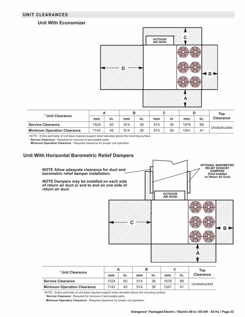
1 Unit ClearanceA B C D Top
Clearancemm in. mm in. mm in mm in.Service Clearance 1524 60 914 36 914 36 1676 66
UnobstructedMinimum Operation Clearance 1143 45 914 36 914 36 1041 41NOTE - Entire perimeter of unit base requires support when elevated above the mounting surface.
1 Service Clearance - Required for removal of serviceable parts. Minimum Operation Clearance - Required clearance for proper unit operation.
Unit With Economizer
C
B
OUTDOORAIR HOOD
A
D
Unit With Horizontal Barometric Relief Dampers
NOTE Allow adequate clearance for duct andbarometric relief damper installation.
NOTE Dampers may be installed on each sideof return air duct or end to end on one side ofreturn air duct.
OPTIONAL BAROMETRICRELIEF EXHAUST
DAMPERS(Field Installed
on Return Air Duct)
OUTDOORAIR HOOD
B
A
C
1 Unit ClearanceA B C Top
Clearancemm in. mm in. mm in.Service Clearance 1524 60 914 36 1676 66
UnobstructedMinimum Operation Clearance 1143 45 914 36 1041 41NOTE - Entire perimeter of unit base requires support when elevated above the mounting surface.1 Service Clearance - Required for removal of serviceable parts. Minimum Operation Clearance - Required clearance for proper unit operation.
UNIT CLEARANCES

Energence® Packaged Electric / Electric 88 to 105 kW - 50 Hz / Page 24
DIMENSIONS UNITCORNER WEIGHTS CENTER OF GRAVITY
Model No. AA BB CC DD EE FFkg lbs. kg lbs. kg lbs. kg lbs. mm in. mm in.
LCH300 Base Unit 277 610 278 612 399 880 406 895 1524 60 940 37LCH300 Max. Unit 315 693 316 696 454 1001 462 1018 1524 60 940 37LCH360 Base Unit 277 610 278 612 399 880 406 895 1524 60 940 37LCH360 Max. Unit 315 693 316 696 454 1001 462 1018 1524 60 940 37Base Unit - The unit with NO INTERNAL OPTIONS.Max. Unit - The unit with ALL INTERNAL OPTIONS Installed. (Economizer, Standard Static Power Exhaust Fans, Controls, etc.). Does not include accessories external to unit or high static power exhaust.
SIDE VIEW
TOP VIEW
END VIEW
FORKLIFT SLOTS(Front and Left Side Only)
2289 (90-1/8)
(31-1/2)800
2305 (90−3/4) 3042 (119−3/4)
3683 (145)
LIFTING HOLES(For Rigging
Front and Back)
BOTTOM POWER ENTRY127 X 203 mm (5 X 8 inches)
BOTTOM SUPPLYAIR OPENINGS
BOTTOM RETURNAIR OPENING
(4-1/4)108
(4-1/2)114
(28)711711
(28)
102 (4)
229 (9)
(5-3/4)146
(17-1/2)445
508 (20) 508 (20)
381 (15)
457 (18)
1994 (78-1/2)
CONDENSATEDRAIN
(5-3/8)137
AA BB
CCDD
CENTER OFGRAVITY
EE
FF
(25-3/4)654
(3-1/4)83
(61-3/4)1568
SIDEELECTRICALINLETS
(65)1651
OPTIONALOUTDOORGRILLE KIT
(Field Installed)(Both Sides)
Energence® Packaged Electric / Electric 88 to 105 kW - 50 Hz / Page 25
DIMENSIONS ACCESSORIES
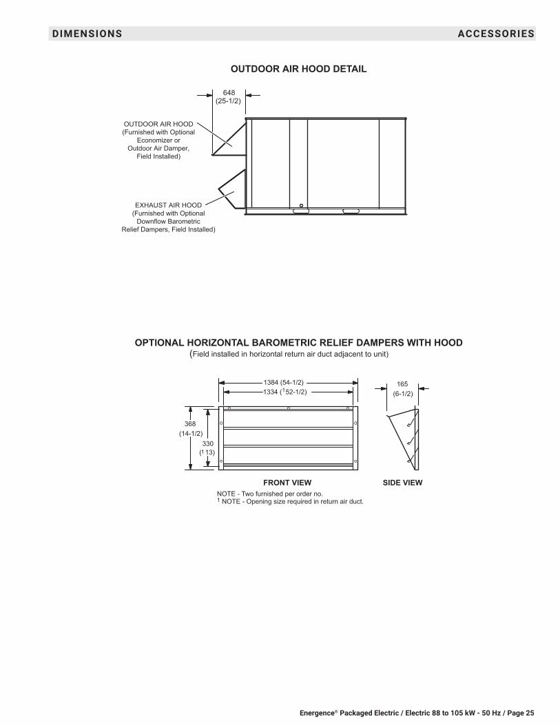
OUTDOOR AIR HOOD DETAIL
OPTIONAL HORIZONTAL BAROMETRIC RELIEF DAMPERS WITH HOOD(Field installed in horizontal return air duct adjacent to unit)
OUTDOOR AIR HOOD(Furnished with Optional
Economizer orOutdoor Air Damper,
Field Installed)
EXHAUST AIR HOOD(Furnished with Optional
Downflow BarometricRelief Dampers, Field Installed)
(25-1/2)648
FRONT VIEW SIDE VIEW
1384 (54-1/2)
(14-1/2)368
1 ( 13)330
(6-1/2)165
1 1334 ( 52-1/2)
NOTE - Two furnished per order no. 1 NOTE - Opening size required in return air duct.

Energence® Packaged Electric / Electric 88 to 105 kW - 50 Hz / Page 26
DIMENSIONS ACCESSORIES
RETURNOPENING
SUPPLYOPENING
NOTE - Roof deck may be omitted within confines of curb.
TYPICAL FLASHING DETAIL FOR ROOF CURB
ROOF CURB(Extends around entire
perimeter of unit)
FIBERGLASSINSULATION
(Furnished)COUNTER FLASHING(Field Supplied)
BASE BOTTOM
RIGID INSULATION(Field Supplied)
ROOFINGMATERIAL
CANT STRIP(Field Supplied)
PACKAGEDUNIT
NAILER STRIP(Furnished)
DETAIL ROOF CURB
FACTORY INSTALLEDPERIMETER WOODNAILER STRIP
HYBRID ROOF CURBS - DOUBLE DUCT OPENING
13 (1/2)
44(1-3/4)
44(1-3/4)
356 (14)457 (18)610 (24)
2835(111-5/8)
1562(61-1/2)
337(13-1/4)
51(2)
2019(79-1/2) 2924
(115-1/8)
356 (14)457 (18)610 (24)
2188(86-1/8)
2099(82-5/8)
533(21)
432(17)
406(16)

Energence® Packaged Electric / Electric 88 to 105 kW - 50 Hz / Page 27
DIMENSIONS ACCESSORIES
ROOF CURBS WITH SUPPLY & RETURN AIR TRANSITIONS FOR CEILING DIFFUSERS
A
LASRT RETURNTRANSITION
LASRT SUPPLYTRANSITION
RETURNAIR OPENING
SUPPLY AIROPENINGS
TOP VIEW
(54)1372
(3/4)19
Typ.
114 (4-1/2)
SUPPORTANGLE
(Furnished withTransitions)
TRANSITION DETAIL
2051 (80-3/4)
(28) 711
1524 (60)
1524 (60)
ASECTION B-B
(26-1/2)673
(28)711
(28) 711
(4-1/2) 114
(28)711
LAS
RT
RE
TUR
NTR
AN
SIT
ION
LAS
RT
SU
PP
LYTR
AN
SIT
ION (14)
356
(2)51
(12)305
(1-1/2) 38
Typ. (26-1/2)673
Energence® Packaged Electric / Electric 88 to 105 kW - 50 Hz / Page 28
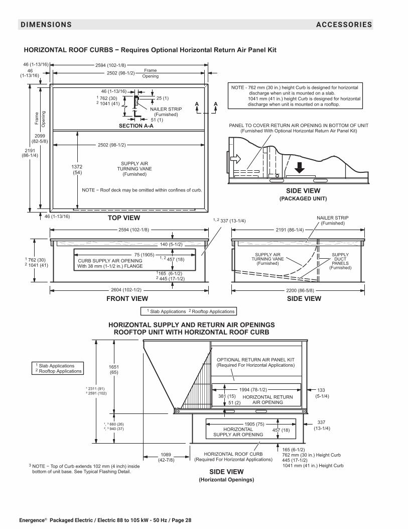
HORIZONTAL ROOF CURBS − Requires Optional Horizontal Return Air Panel Kit
(13-1/4) 337¹, ³ 660 (26)
², ³ 940 (37)
165 (6-1/2)
445 (17-1/2)3 NOTE − Top of Curb extends 102 mm (4 inch) inside
bottom of unit base. See Typical Flashing Detail. SIDE VIEW(Horizontal Openings)
HORIZONTAL ROOF CURB(Required For Horizontal Applications)
HORIZONTAL RETURNAIR OPENING
(5-1/4)133
381 (15)1994 (78-1/2)
1651(65)
HORIZONTALSUPPLY AIR OPENING
1905 (75)457 (18)
51 (2)
OPTIONAL RETURN AIR PANEL KIT(Required For Horizontal Applications)
(42-7/8)1089
HORIZONTAL SUPPLY AND RETURN AIR OPENINGSROOFTOP UNIT WITH HORIZONTAL ROOF CURB
1 762 (30)2 1041 (41)
2594 (102-1/8)
SIDE VIEW
TOP VIEW
Fram
eO
peni
ng
FrameOpening
(54) 1372
2502 (98-1/2)
(82-5/8)2099
2200 (86-5/8)
2502 (98-1/2)
FRONT VIEW
NAILER STRIP(Furnished)
2604 (102-1/2)
CURB SUPPLY AIR OPENINGWith 38 mm (1-1/2 in.) FLANGE
75 (1905)
140 (5-1/2)
SUPPLYDUCT
PANELS(Furnished)
SUPPLY AIRTURNING VANE
(Furnished)
25 (1)
51 (1)SECTION A-A
46 (1-13/16)
NAILER STRIP(Furnished)
AA
2594 (102-1/8) 2191 (86-1/4)
NOTE − Roof deck may be omitted within confines of curb.
SUPPLY AIRTURNING VANE
(Furnished)
PANEL TO COVER RETURN AIR OPENING IN BOTTOM OF UNIT(Furnished With Optional Horizontal Return Air Panel Kit)
SIDE VIEW(PACKAGED UNIT)
46 (1-13/16)
(1-13/16)46
46 (1-13/16)
1, 2 337 (13-1/4)
1165 (6-1/2)2 445 (17-1/2)
1 762 (30)2 1041 (41)
1, 2
457 (18)
(86-1/4)2191
NOTE - 762 mm (30 in.) height Curb is designed for horizontal discharge when unit is mounted on a slab. 1041 mm (41 in.) height Curb is designed for horizontal discharge when unit is mounted on a rooftop.
1 Slab Applications 2 Rooftop Applications
¹ 2311 (91)² 2591 (102)
762 mm (30 in.) Height Curb
1041 mm (41 in.) Height Curb
1 Slab Applications 2 Rooftop Applications
DIMENSIONS ACCESSORIES

Energence® Packaged Electric / Electric 88 to 105 kW - 50 Hz / Page 29
Model Number LARTD30/36SA mm 1667
in. 65-5/8 B mm 1667
in. 65-5/8 C mm 1029
in. 40-1/2 D mm 1613
in. 63-1/2E mm 1613
in 63-1/2F mm 114
in 4-1/2G mm 711
in. 28H mm 38
in. 1-1/2J mm 1524
in. 60K mm 44
in. 1-3/4L mm 1613
in. 63-1/2M mm 1613
in. 63-1/2N mm 308
in. 12-1/8Duct Size mm 711 x 1524
in. 28 x 60
Model Number LAFD30/36SA mm 1667
in. 65-5/8B mm 1667
in. 65-5/8C mm 1016
in. 40D mm 1613
in. 63-1/2E mm 1613
in. 63-1/2F mm 108
in. 4-1/4G mm 711
in 28H mm 32
in. 1-5/8J mm 1524
in. 60K mm 44
in. 1-3/4Duct Size mm 711 x 1524
in. 28 x 60
COMBINATION CEILING SUPPLY AND RETURN DIFFUSERSRESUFFID GNILIEC HSULFRESUFFID GNILIEC NWOD-PETS
L
A
C
HJG
FE
B
M
N
K
DG
51 (2)
A
C
HJG
FE
B
K
DG
51 (2)
DIMENSIONS ACCESSORIES


REVISIONS
REVISIONS
Sections Description of Change
Options/Accessories Catalog numbers revised for:Blower Proving SwitchDrain Pan Overflow SwitchFresh Air TemperingSingle Enthalpy
NOTE - Due to Lennox’ ongoing commitment to quality, Specifications, Ratings and Dimensions subject to change without notice and without incurring liability. Improper installation, adjustment, alteration, service or maintenance can cause property damage or personal injury. Installation and service must be performed by a qualified installer and servicing agency. ©2021 Lennox Industries, Inc.
Visit us at www.lennox.com For the latest technical information, www.lennoxcommercial.com Contact us at 1-800-4-LENNOX