Embed Size (px)
Citation preview

KGB Landmark® Rooftop Units
Standard and High Efficiency - 60 Hz
2 to 7.5 TonsNet Cooling Capacity − 24,200 to 88,000 Btuh
Gas Input Heat Capacity − 65,000 to 150,000 Btuh
K G B 060 S 4 B S 1 YBrand/Family
K = Landmark® Product Line
Unit Type G = Packaged Gas Heat w/ Electric Cooling
Major Design Sequence B = 2nd Generation
Nominal Cooling Capacity - Tons 024 = 2 Tons
030 = 2.5 Tons 036 = 3 Tons 048 = 4 Tons 060 = 5 Tons 072 = 6 Tons 074 = 6 Tons
090 = 7.5 Tons
Cooling Efficiency H = High Efficiency
S = Standard Efficiency
Refrigerant Type 4 = R-410A
Blower Type D = Direct Drive (PSC) E = Direct Drive (ECM) B = Belt Drive T = Belt Drive (2 Speed)
Heating Type S = Standard Gas Heat, 1 stage M = Medium Gas Heat, 1 stage U = Medium Gas Heat, 2 Stage T = High Gas Heat, 1 Stage H = High Gas Heat, 2 Stage W = Standard Gas Heat, 1 Stage, Low NOx B = Standard Gas Heat, 2 Stage Low NOx Y = Medium Gas Heat, 1 Stage, Low NOx Q = Medium Gas Heat, 2 Stage, Low NOx Z = High Gas Heat, 1 Stage, Low NOx X = High Gas Heat, 2 Stage, Low NOx
Minor Design Sequence 1 = 1st Revision 2 = 2nd Revision 3 = 3rd Revision
Voltage P = 208/230V−1 phase-60hz Y = 208/230V-3 phase-60hz G = 460V-3 phase-60hz J = 575V-3 phase-60hz
ASHRAE 90.1COMPLIANT
Bulletin No. 210786 March 2021
Supersedes September 2020
KGB 2-6 TON ROOFTOP UNITS
PA C K A G E D G A S / E L E C T R I C
C O M M E R C I A L P R O D U C T S P E C I F I C AT I O N S
MODEL NUMBER IDENTIFICATION

Landmark® Packaged Gas / Electric 2 to 6 Tons / Page 2
Landmark® rooftop units from Lennox® are the new standard for reliable, efficient rooftop units built for long-lasting performance that can significantly improve indoor environments.
FEATURE HIGHLIGHTS
1. Heat Exchanger2. Electronic Pilot Ignition3. Scroll Compressor4. Thermal Expansion Valves5. Lennox’ Environ™ Coil System6. Outdoor Coil Fan Motors7. Heavy Gauge Steel Cabinet8. Power Entry9. Insulation10. Hinged Access Panels (option)11. Supply Air Blower12. Air Filters13. Economizer (option)14. Power Exhaust Fans (option, not shown)
CONTENTS
Approvals and Warranty . . . . . . . . . . . . . . . . . . . . . . . . . . . . . . . . . . . . . . . . . . . . . . . . . . 3Blower Data . . . . . . . . . . . . . . . . . . . . . . . . . . . . . . . . . . . . . . . . . . . . . . . . . . . . . . . . 31Dimensions - Accessories . . . . . . . . . . . . . . . . . . . . . . . . . . . . . . . . . . . . . . . . . . . . . . . . 58Dimensions - Unit . . . . . . . . . . . . . . . . . . . . . . . . . . . . . . . . . . . . . . . . . . . . . . . . . . . . . 57Electrical Data . . . . . . . . . . . . . . . . . . . . . . . . . . . . . . . . . . . . . . . . . . . . . . . . . . . . . . . 48Features And Benefits . . . . . . . . . . . . . . . . . . . . . . . . . . . . . . . . . . . . . . . . . . . . . . . . . . . 3High Altitude Derate . . . . . . . . . . . . . . . . . . . . . . . . . . . . . . . . . . . . . . . . . . . . . . . . . . . 24Humiditrol® Dehumidification System Option . . . . . . . . . . . . . . . . . . . . . . . . . . . . . . . . . . . . . 12Humiditrol® Dehumidification System Ratings . . . . . . . . . . . . . . . . . . . . . . . . . . . . . . . . . . . . . 29Model Number Identification. . . . . . . . . . . . . . . . . . . . . . . . . . . . . . . . . . . . . . . . . . . . . . . . 1Optional Conventional Temperature Control Systems . . . . . . . . . . . . . . . . . . . . . . . . . . . . . . . . 11Options / Accessories . . . . . . . . . . . . . . . . . . . . . . . . . . . . . . . . . . . . . . . . . . . . . . . . . . 13Outdoor Sound Data . . . . . . . . . . . . . . . . . . . . . . . . . . . . . . . . . . . . . . . . . . . . . . . . . . . 47Ratings . . . . . . . . . . . . . . . . . . . . . . . . . . . . . . . . . . . . . . . . . . . . . . . . . . . . . . . . . . . 25Specifications - Belt Drive Blower . . . . . . . . . . . . . . . . . . . . . . . . . . . . . . . . . . . . . . . . . . . . 20Specifications - Direct Drive Blower . . . . . . . . . . . . . . . . . . . . . . . . . . . . . . . . . . . . . . . . . . . 17Specifications - Low NOx Gas Heat . . . . . . . . . . . . . . . . . . . . . . . . . . . . . . . . . . . . . . . . . . . 24Specifications - Standard Gas Heat . . . . . . . . . . . . . . . . . . . . . . . . . . . . . . . . . . . . . . . . . . . 24Unit Clearances . . . . . . . . . . . . . . . . . . . . . . . . . . . . . . . . . . . . . . . . . . . . . . . . . . . . . . 55Weight Data . . . . . . . . . . . . . . . . . . . . . . . . . . . . . . . . . . . . . . . . . . . . . . . . . . . . . . . . 56
BB
CCOO NN
MMLL
KK
JJ
II
HH
GG
FF
EE
DD

Landmark® Packaged Gas / Electric 2 to 6 Tons/ Page 3
HEATING SYSTEM• Aluminized steel inshot burners• Direct spark ignition• Electronic flame sensor• Combustion air inducer• Redundant automatic single or dual stage gas valve with
manual shut-off
Heat Exchanger• Tubular construction• Aluminized steel• Life cycle testedNOTE - Stainless Steel Heat Exchanger is required if mixed
air temperature is below 45°F.
Electronic Pilot Ignition• Electronic spark igniter provides positive direct ignition
of burners on each operating cycle• System permits main gas valve to stay open only when
the burners are proven to be lit• Should a loss of flame occur, the gas valve closes,
shutting off the gas to the burners• Ignition module has LED to indicate status and aid in
troubleshooting
BB
CC
APPROVALS AND WARRANTY
APPROVALS• AHRI Standard 210/240 certified (2 - 5 ton models)• AHRI Standard 340/360 certified (6 and 7.5 ton models)• ETL and CSA listed• CSA certified energy ratings• Unit and components ETL, NEC and CEC bonded for grounding to meet safety standards for servicing• All models are ASHRAE 90.1 compliant• ISO 9001 Registered Manufacturing Quality SystemNOTE - All single phase models and models equipped with low NOx gas heat option meet the California Nitrogen Oxides
Standard (NOx) limits of 40 ng/J that apply in the South Coast Air Quality Management District and the San Francisco Bay Area Air Quality Management District.
California Only• If installed in South Coast Air Quality Management District (SCAQMD) only:
• This gas unit does not meet the SCAQMD Rule 1111 NOx emission limit (14 ng/J), and thus is subject to a mitigation fee of up to $450. This furnace is not eligible for the Clean Air Furnace Rebate Program: www.CleanAirFurnaceRebate.com.
• If installed in San Joaquin Valley Air Pollution Control District (SJVAPCD) only• This gas unit does not meet the SJVAPCD Rule 4905 NOx emission limit (14 ng/J), and thus is subject to a mitigation
fee of up to $450
WARRANTY• Aluminized steel heat exchanger - Limited ten years• Stainless steel heat exchanger (optional) - Limited fifteen years• Compressors - Limited five years• Lennox’ Environ™ Coil System - Limited three years• Optional High Performance Economizers - Limited five years• All other covered components - Limited one year
FEATURES AND BENEFITS
• Watchguard circuit on module automatically resets ignition controls after one hour of continuous thermostat demand after unit lockout, eliminating nuisance service calls
• Ignition control is factory installed in the controls section
Limit Controls• Factory installed• Redundant limit controls with fixed temperature setting• Protect heat exchanger and other components from
overheating
Safety Switches• Flame roll-out switch• Flame sensor and combustion air inducer proving switch
protect system operation
Low NOx Models• All single phase models are available in low NOx
versions (40 ng/J)

Landmark® Packaged Gas / Electric 2 to 6 Tons / Page 4
FEATURES AND BENEFITS
HEATING SYSTEM (continued)
Required Selections
Gas Input Choice - Order one:• Standard Gas Heat (1 Stage) 65,000 Btuh• Standard Gas Heat (2 Stage) 70,000/53,000 Btuh• Medium Gas Heat (1 Stage) 108,000 Btuh• Medium Gas Heat (2 Stage) 81,000/108,000 Btuh• High Gas Heat (1 Stage) 150,000 Btuh• High Gas Heat (2 Stage) 113,000/150,000 Btuh
Standard or Low NOx• Specify standard gas heat or Low NOx (40 ng/J) option
(three phase models only)NOTE - All single phase models are Low NOx (40 ng/J)
equipped.NOTE - Standard Gas Heat
(2 Stage) is only available with Low NOx models.
Options/Accessories
Factory InstalledStainless Steel Heat Exchanger• Required if mixed air temperature is below 45°F
Field InstalledCombustion Air Intake Extensions• Recommended for use with existing flue extension kits
in areas where high snow areas can block intake air
Low Temperature Vestibule Heater• Electric heater automatically controls minimum
temperature in gas burner compartment when temperature is below -40°F
• C.S.A.certified to allow operation of unit down to -60°F
LPG/Propane Kits• Conversion kit to field change over units from Natural
Gas to LPG/Propane
Vertical Vent Extension Kit• Use to exhaust flue gases vertically above unit• Required when unit vent is too close to fresh air intakes
per building codes• Also prevents ice formation on intake louvers
COOLING SYSTEM• Designed to maximize sensible and latent cooling
performance at design conditions• System can operate from 30°F to 125°F without any
additional controls
R-410A Refrigerant• Non-chlorine based• Ozone-friendly
Single Speed Scroll Compressor (024 through 072 Models)• High performance, reliability and quiet operation• Resiliently mounted on rubber grommets for quiet
operation
DD
Two-Stage Scroll Compressor (074 and 090 Models)• Two-stage for increased part load efficiency, high
performance, reliability and quiet operation• Resiliently mounted on rubber grommets for quiet
operation
Compressor Crankcase Heater• Protects against refrigerant migration that can occur
during low ambient operation
Thermal Expansion Valve • Assures optimal performance throughout the application
range• Removable element head
High Pressure Switch• Protects the compressor from overload conditions such
as dirty condenser coils, blocked refrigerant flow, or loss of outdoor fan operation
Filter/Drier• High capacity filter/drier protects the system from dirt
and moisture
Freezestat• Protects the evaporator coil from damaging ice build-up
due to conditions such as low/no air flow, or low refrigerant charge
Lennox’ Environ™ Coil System • Lightweight, all aluminum brazed
fin construction• Constructed of three components:
• A flat extrusion tube• Fins in-between the flat
extrusion tube• Two refrigerant manifolds
Environ™ Coil System Features:• Improved heat transfer performance due to high primary
surface area (flat tubes) versus secondary surface (fins)• Smaller internal volume (reduced refrigerant charge)• High durability• All aluminum construction• Fewer brazed joints• Compact design• Reduced unit weight• Easy maintenance/cleaning• Mounting brackets with rubber inserts
EE
FF

Landmark® Packaged Gas / Electric 2 to 6 Tons/ Page 5
FEATURES AND BENEFITS
COOLING SYSTEM (continued)
Evaporator Coil• Copper tube construction• Ehanced rippled-edge aluminum fins• Flared shoulder tubing connections• Silver soldered construction• Factory leak tested• Cross row circuiting with rifled tubing
Condensate Drain Pan• Plastic pan, sloped to meet drainage requirements of
ASHRAE 62.1• Side or bottom drain connections• Reversible to allow connection at back of unit
Outdoor Coil Fan Motor• Thermal overload protected• Totally enclosed• Permanently lubricated sleeve bearings (024, 030, 036
and 048 models)• Permanently lubricated ball bearings (060, 072, 074, and
090 models)• Shaft up• Wire basket mount
Outdoor Coil Fan• PVC coated fan guard furnished
Required Selections
Cooling Capacity• Specify nominal cooling capacity
Options/Accessories
Factory InstalledConventional Fin/Tube Condenser Coil (replaces Environ™ Coil System) (All except 072 and 074H)• Copper tube construction• Enhanced rippled-edge aluminum fins• Flared shoulder tubing connections• Silver soldered constructionNOTE - Required if Humiditrol® Dehumidification System
is ordered.
Field InstalledCondensate Drain Trap• Field installed only• Available in copper or PVC
Drain Pan Overflow Switch• Monitors condensate level in drain pan, shuts down unit
if drain becomes clogged
GG
Low Ambient Kit (0°F)• Cycles the outdoor fan while allowing compressor
operation in the cooling cycle• This intermittent fan operation allows the system to operate
without icing the evaporator coil and losing capacity• Designed for use in ambient temperatures no lower than 0°FNOTE - A crankcase heater must be installed on the
compressor.
CABINET
Construction• Heavy-gauge steel panels• Two-layer enamel paint finish• Full perimeter heavy-gauge galvanized steel base rail• Base rails have rigging holes• Three sides of the base rail have forklift slots• Raised edges around duct and power entry openings in
the bottom of the unit for water protection
Airflow Choice• Units are shipped in downflow (vertical) return air
configuration• Can be field converted to horizontal air flow
configuration without the need of a kit
Power/Gas Entry• Electrical and gas lines can be brought through the unit
base or through horizontal access knock-outsNOTE - Optional Bottom Gas Entry Kit is available.
Insulation• Fully insulated with non-hygroscopic fiberglass
insulation (conditioned areas)• Unit base is fully insulated• Base insulation serves as an air seal to the roof curb,
eliminating the need to add a seal during installation
Access Panels• Economizer/Filter section• Heating/Blower section• Compressor/Controls sectionNOTE - KGB060/074/090 models include a filler panel
for proper cabinet fit for optional accessories (Economizers, Power Exhaust, Outdoor Air Dampers and Barometric Relief Dampers).
HH
II
JJ
Landmark® Packaged Gas / Electric 2 to 6 Tons / Page 6
CABINET (continued)
Options/Accessories
Factory InstalledCorrosion Protection• Completely flexible immersed coating• Electrodeposited dry film process• AST ElectroFin E-Coat• Meets Mil Spec MIL-P-53084, ASTM B117 Standard
Method Salt Spray Testing• Indoor Corrosion Protection:
• Coated coil• Coated reheat coil (Humiditrol®)• Painted blower housing• Painted base
• Outdoor Corrosion Protection:• Coated coil• Painted outdoor base
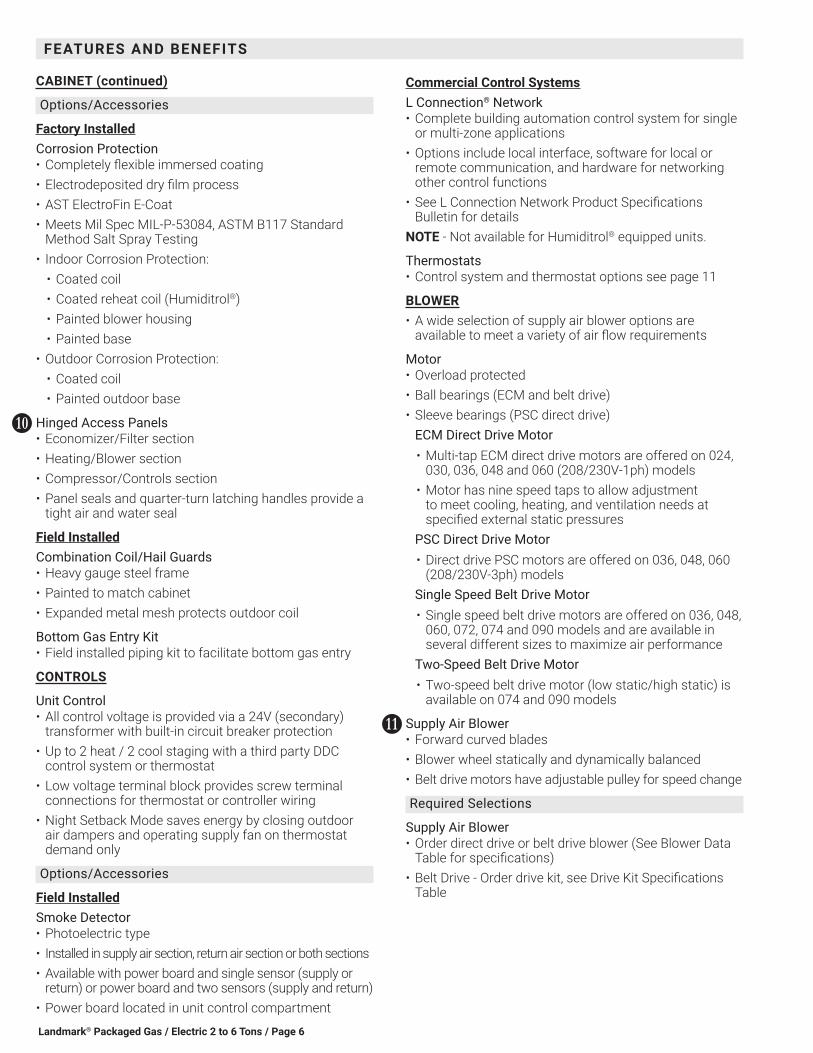
Hinged Access Panels• Economizer/Filter section• Heating/Blower section• Compressor/Controls section• Panel seals and quarter-turn latching handles provide a
tight air and water seal
Field InstalledCombination Coil/Hail Guards• Heavy gauge steel frame• Painted to match cabinet• Expanded metal mesh protects outdoor coil
Bottom Gas Entry Kit• Field installed piping kit to facilitate bottom gas entry
CONTROLS
Unit Control• All control voltage is provided via a 24V (secondary)
transformer with built-in circuit breaker protection• Up to 2 heat / 2 cool staging with a third party DDC
control system or thermostat• Low voltage terminal block provides screw terminal
connections for thermostat or controller wiring• Night Setback Mode saves energy by closing outdoor
air dampers and operating supply fan on thermostat demand only
Options/Accessories
Field InstalledSmoke Detector• Photoelectric type• Installed in supply air section, return air section or both sections• Available with power board and single sensor (supply or
return) or power board and two sensors (supply and return)• Power board located in unit control compartment
KK
Commercial Control SystemsL Connection® Network• Complete building automation control system for single
or multi-zone applications• Options include local interface, software for local or
remote communication, and hardware for networking other control functions
• See L Connection Network Product Specifications Bulletin for details
NOTE - Not available for Humiditrol® equipped units.
Thermostats• Control system and thermostat options see page 11
BLOWER• A wide selection of supply air blower options are
available to meet a variety of air flow requirements
Motor• Overload protected• Ball bearings (ECM and belt drive)• Sleeve bearings (PSC direct drive)
ECM Direct Drive Motor• Multi-tap ECM direct drive motors are offered on 024,
030, 036, 048 and 060 (208/230V-1ph) models• Motor has nine speed taps to allow adjustment
to meet cooling, heating, and ventilation needs at specified external static pressures
PSC Direct Drive Motor• Direct drive PSC motors are offered on 036, 048, 060
(208/230V-3ph) modelsSingle Speed Belt Drive Motor• Single speed belt drive motors are offered on 036, 048,
060, 072, 074 and 090 models and are available in several different sizes to maximize air performance
Two-Speed Belt Drive Motor• Two-speed belt drive motor (low static/high static) is
available on 074 and 090 models
Supply Air Blower• Forward curved blades• Blower wheel statically and dynamically balanced• Belt drive motors have adjustable pulley for speed change
Required Selections
Supply Air Blower• Order direct drive or belt drive blower (See Blower Data
Table for specifications)• Belt Drive - Order drive kit, see Drive Kit Specifications
Table
LL
FEATURES AND BENEFITS
Landmark® Packaged Gas / Electric 2 to 6 Tons/ Page 7
ELECTRICAL• All units include terminal block and fuse block in power
entry junction box for single power entry application
Marked & Color-Coded Wiring• All electrical wiring is color-coded and marked to identify
which components it is connecting
Electrical Plugs• Positive connection electrical plugs are used to connect
common accessories or maintenance parts for easy removal or installation
Required Selections
Voltage Choice• Specify when ordering base unit
Options/Accessories
Factory or Field InstalledDisconnect Switch• Accessible from outside of unit• Spring loaded weatherproof cover furnished
GFI Service Outlets (2)• 115V ground fault circuit interrupter (GFCI) type• Non-powered• Field-wired
GFI Weatherproof Cover• Single-gang cover• Heavy-duty UV-resistant polycarbonate case construction• Hinged base cover with gasket
INDOOR AIR QUALITY
Air Filters• Disposable 2 inch filters furnished as standard
Options/Accessories
Field InstalledHealthy Climate® High Efficiency Air Filters• Disposable MERV 8 or MERV 13 (Minimum Efficiency
Reporting Value based on ASHRAE 52.2) efficiency 2 inch pleated filters
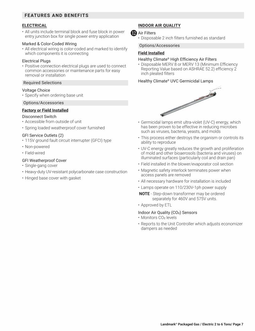
Healthy Climate® UVC Germicidal Lamps
• Germicidal lamps emit ultra-violet (UV-C) energy, which has been proven to be effective in reducing microbes such as viruses, bacteria, yeasts, and molds
• This process either destroys the organism or controls its ability to reproduce
• UV-C energy greatly reduces the growth and proliferation of mold and other bioaerosols (bacteria and viruses) on illuminated surfaces (particularly coil and drain pan)
• Field installed in the blower/evaporator coil section• Magnetic safety interlock terminates power when
access panels are removed• All necessary hardware for installation is included• Lamps operate on 110/230V-1ph power supply NOTE - Step-down transformer may be ordered
separately for 460V and 575V units.• Approved by ETL
Indoor Air Quality (CO2) Sensors• Monitors CO2 levels• Reports to the Unit Controller which adjusts economizer
dampers as needed
MM
FEATURES AND BENEFITS
Landmark® Packaged Gas / Electric 2 to 6 Tons / Page 8
OPTIONS/ACCESSORIES
ECONOMIZER
Factory or Field InstalledEconomizer (Standard and High Performance Common Features)• Combination Outdoor Air Hood is furnished• Factory installed Economizer can be ordered with two
exhaust options:• Barometric Relief Dampers• No Exhaust
• Field installed Economizer includes Barometric Relief Dampers with Combination Hood
• Barometric Relief Dampers allow relief of excess air, dampers prevent blow back and outdoor air infiltration during off cycle, bird screen furnished
NOTE - Barometric Relief Dampers are required when Economizer is factory installed with field installed Power Exhaust Fan option. See Power Exhaust Fan section and Options/Accessories table.
• Occupied/Unoccupied mode with field furnished setback thermostat
• Demand Control Ventilation (DCV) ready using optional CO2 sensors
• Mixed Air Sensor is furnished for field installation in the rooftop unit
NOTE - Sensor is factory installed when Economizers are factory installed.
• Single sensible sensor is furnished with Economizer and enables economizer operation if the outdoor temperature is less than the setpoint of the control
• Horizontal Barometric Dampers are required for horizontal Economizer applications and must be ordered separately
Standard Economizer Features (Not for Title 24)• Gear-driven action• Return air and outdoor air dampers• Plug-in connections to unit• Neoprene seals• 24-volt, fully-modulating spring return motor
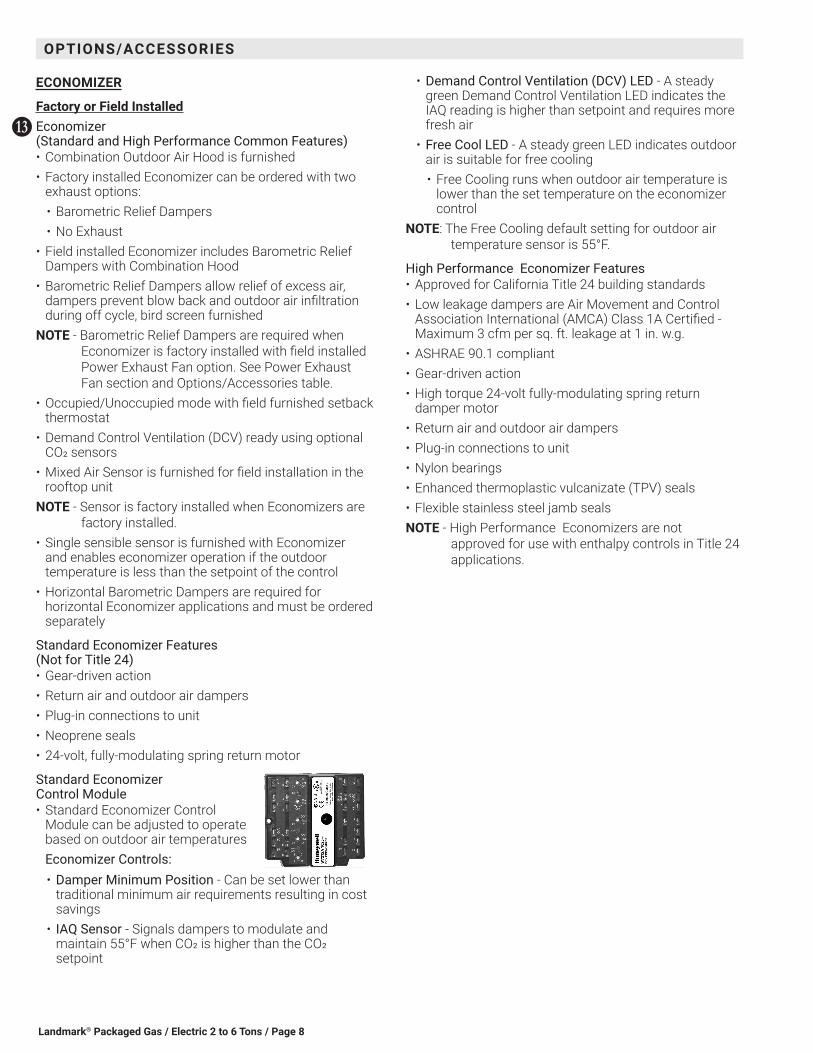
Standard Economizer Control Module• Standard Economizer Control
Module can be adjusted to operate based on outdoor air temperaturesEconomizer Controls:• Damper Minimum Position - Can be set lower than
traditional minimum air requirements resulting in cost savings
• IAQ Sensor - Signals dampers to modulate and maintain 55°F when CO2 is higher than the CO2 setpoint
NN
• Demand Control Ventilation (DCV) LED - A steady green Demand Control Ventilation LED indicates the IAQ reading is higher than setpoint and requires more fresh air
• Free Cool LED - A steady green LED indicates outdoor air is suitable for free cooling• Free Cooling runs when outdoor air temperature is
lower than the set temperature on the economizer control
NOTE: The Free Cooling default setting for outdoor air temperature sensor is 55°F.
High Performance Economizer Features• Approved for California Title 24 building standards• Low leakage dampers are Air Movement and Control
Association International (AMCA) Class 1A Certified - Maximum 3 cfm per sq. ft. leakage at 1 in. w.g.
• ASHRAE 90.1 compliant• Gear-driven action• High torque 24-volt fully-modulating spring return
damper motor• Return air and outdoor air dampers• Plug-in connections to unit• Nylon bearings• Enhanced thermoplastic vulcanizate (TPV) seals• Flexible stainless steel jamb sealsNOTE - High Performance Economizers are not
approved for use with enthalpy controls in Title 24 applications.

Landmark® Packaged Gas / Electric 2 to 6 Tons/ Page 9
ECONOMIZER (continued)
High Performance Economizer Control Module • Module provides inputs and
outputs to control economizer based on parameter settings
• Module automatically detects sensors by polling to determine which sensors are installed in system
• Module displays any alarm messages (fault detection and diagnostics) as an aid in troubleshooting
• Non-volatile memory retains parameter settings in case of power failure
• Keypad with four navigation buttons and LCD screen is furnished for setting economizer parameters:• Menu Up/Exit button returns to the main menu• Arrow Up button moves to the previous or next
parameter within the selected menu• Arrow Down button moves to the next parameter
within the selected menu• Select (enter) button confirms parameter selection
Main Menu Structure:• Status (economizer and system operation status)• Setpoints (settings for various setpoint parameters)• System Setup (settings/information about the system)• Advanced Setup (freeze protection, CO2 settings, stage
3 delay and additional calibration settings)• Checkout (damper positions)• Alarms (output signal that can be configured for
remote alarm monitoring)NOTE - The Free Cooling setpoint for Title 24 applications
must be set based on the Climate Zone where the system is installed. See Section 140.4 “Prescriptive Requirements for Space Conditioning Systems” of the California Energy Commission’s 2013 Building Energy Efficiency Standards.
NOTE - Refer to Installation Instructions for complete setup information and menu parameters available.
Factory or Field InstalledSingle Enthalpy Temperature Control (Not for Title 24)• Outdoor air enthalpy sensor enables Economizer if the
outdoor enthalpy is less than the setpoint of the control
Field InstalledDifferential Enthalpy Control (Not for Title 24)• Order two Single Enthalpy Controls• One is field installed in the return air section, the other in
the outdoor air section• Allows the economizer control board to select between
outdoor air or return air, whichever has lower enthalpy
OPTIONS/ACCESSORIES
EXHAUST
Field InstalledHorizontal Barometric Relief Dampers• For use when unit is configured for horizontal
applications with an economizer• Allows relief of excess air• Blade type dampers prevent blow back and outdoor air
infiltration during off cycle• Field installed in return air duct• Exhaust hood with bird screen furnishedNOTE - Requires Horizontal Economizer Conversion Kit.
Horizontal Economizer Conversion Kit• Insulated panel covers the bottom return air opening
on the unit base to convert downflow Economizer to horizontal airflow
Power Exhaust Fan• Installs internal to unit for downflow applications only
with Economizer option• Provides exhaust air pressure relief• Interlocked to run when supply air blower is operating,
fan runs when outdoor air dampers are 50% open (adjustable)
• Motor is overload protected.• 16 in. diameter fan• 4 fan blades• 1/3 hp motorNOTE - Not available for 024 and 030 models.NOTE - If Power Exhaust is field installed with a factory
installed Economizer, the Economizer must be ordered with No Exhaust option. Barometric Relief Dampers must also be ordered separately for field installation.
OUTDOOR AIR
Factory or Field InstalledOutdoor Air Dampers - Downflow or Horizontal With Air Hood• Single blade damper• 0 to 25% (fixed) outdoor air adjustable• Installs in unit• Includes outdoor air hood• Automatic model features fully modulating spring return
damper motor with plug-in connection• Manual model features a slide damper• Maximum mixed air temperature in cooling mode: 100°F
OO

Landmark® Packaged Gas / Electric 2 to 6 Tons / Page 10
OPTIONS/ACCESSORIES
ROOF CURBS
Field Installed• Nailer strip furnished• Mates to unit• US National Roofing Contractors Approved• Shipped knocked down
Hybrid Roof Curbs• Downflow• Interlocking tabs fasten corners together• No tools required• Can also be fastened together with furnished hardware• Available in 8, 14, 18, and 24 inch heights
Full Perimeter Curbs, Downflow (090 Models Only)• Hybrid roof curbs can be assembled using interlocking
tabs to fasten corners together• No tools required.• Can also be fastened together with furnished hardware• Available in 8, 14, 18, and 24 inch heightsNOTE - 090 models can be used on smaller 79-3/4 in.
Hybrid Roof Curbs (not full perimeter) with 15-3/4 in. overhang at condenser end of unit. See dimension drawing on page 60.
Adjustable Pitch Curb• Downflow• Fully adjustable pitch curbs (3/4 in. per foot in any
direction) provide a level platform for rooftop units allowing flexible installations on roofs with uneven or sloped angles
• Uses interlocking tabs to fasten corners together. No tools required
• Hardware is furnished to connect upper curb with lower curb
• Available in 14 inch height
Adaptor Curbs (not shown)• Curbs are regionally sourced• Dimensions vary based upon the sourceNOTE - Contact your local sales representative for a
detailed cut sheet with applicable dimensions.
CEILING DIFFUSERS
Field InstalledCeiling Diffusers (Flush or Step-Down)• White powder coat finish on diffuser face and grilles• Insulated UL listed duct liner• Diffuser box has collars for duct connection• Step-down diffusers have double deflection blades• Flush diffusers have fixed blades• Provisions for suspending• Internally sealed to prevent recirculation• Removable return air grille• Adapts to T-bar ceiling grids or plaster ceilings
Transitions (Supply and Return)• Used with diffusers• Installs in roof curb• Galvanized steel construction• Flanges furnished for duct connection to diffusers• Fully insulated
Landmark® Packaged Gas / Electric 2 to 6 Tons/ Page 11
OPTIONAL CONVENTIONAL TEMPERATURE CONTROL SYSTEMS
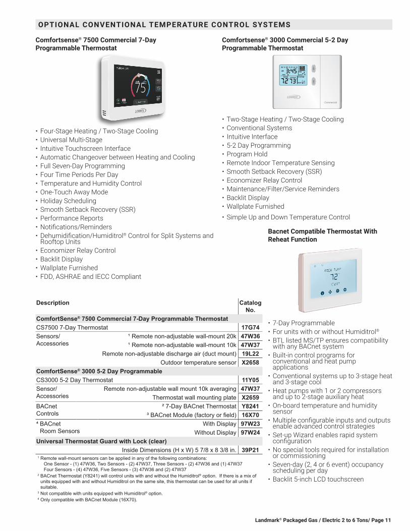
Comfortsense® 7500 Commercial 7-Day Programmable Thermostat
• Four-Stage Heating / Two-Stage Cooling• Universal Multi-Stage• Intuitive Touchscreen Interface• Automatic Changeover between Heating and Cooling• Full Seven-Day Programming• Four Time Periods Per Day• Temperature and Humidity Control• One-Touch Away Mode• Holiday Scheduling• Smooth Setback Recovery (SSR)• Performance Reports• Notifications/Reminders• Dehumidification/Humiditrol® Control for Split Systems and
Rooftop Units• Economizer Relay Control• Backlit Display• Wallplate Furnished• FDD, ASHRAE and IECC Compliant
Comfortsense® 3000 Commercial 5-2 Day Programmable Thermostat
MAINT
Commercial
• Two-Stage Heating / Two-Stage Cooling• Conventional Systems• Intuitive Interface• 5-2 Day Programming• Program Hold• Remote Indoor Temperature Sensing• Smooth Setback Recovery (SSR)• Economizer Relay Control• Maintenance/Filter/Service Reminders• Backlit Display• Wallplate Furnished• Simple Up and Down Temperature Control
Bacnet Compatible Thermostat With Reheat Function
• 7-Day Programmable• For units with or without Humiditrol®• BTL listed MS/TP ensures compatibility
with any BACnet system• Built-in control programs for
conventional and heat pump applications
• Conventional systems up to 3-stage heat and 3-stage cool
• Heat pumps with 1 or 2 compressors and up to 2-stage auxiliary heat
• On-board temperature and humidity sensor
• Multiple configurable inputs and outputs enable advanced control strategies
• Set-up Wizard enables rapid system configuration
• No special tools required for installation or commissioning
• Seven-day (2, 4 or 6 event) occupancy scheduling per day
• Backlit 5-inch LCD touchscreen
Description Catalog No.
ComfortSense® 7500 Commercial 7-Day Programmable ThermostatCS7500 7-Day Thermostat 17G74Sensors/Accessories
¹ Remote non-adjustable wall-mount 20k 47W36¹ Remote non-adjustable wall-mount 10k 47W37
Remote non-adjustable discharge air (duct mount) 19L22Outdoor temperature sensor X2658
ComfortSense® 3000 5-2 Day ProgrammableCS3000 5-2 Day Thermostat 11Y05Sensor/Accessories
Remote non-adjustable wall mount 10k averaging 47W37Thermostat wall mounting plate X2659
BACnet Controls
² 7-Day BACnet Thermostat Y8241³ BACnet Module (factory or field) 16X70
⁴ BACnet Room Sensors
With Display 97W23Without Display 97W24
Universal Thermostat Guard with Lock (clear)Inside Dimensions (H x W) 5 7/8 x 8 3/8 in. 39P21
1 R emote wall-mount sensors can be applied in any of the following combinations: One Sensor - (1) 47W36, Two Sensors - (2) 47W37, Three Sensors - (2) 47W36 and (1) 47W37 Four Sensors - (4) 47W36, Five Sensors - (3) 47W36 and (2) 47W37
2 BACnet Thermostat (Y8241) will control units with and without the Humiditrol® option. If there is a mix of units equipped with and without Humiditrol on the same site, this thermostat can be used for all units if suitable.
3 Not compatible with units equipped with Humiditrol® option.4 Only compatible with BACnet Module (16X70).
Landmark® Packaged Gas / Electric 2 to 6 Tons / Page 12
OVERVIEWNOTE - Not available with Environ™ Coil System.
Conventional Fin/Tube condenser coil must be ordered as a factory option.
• Factory installed option designed to control humidity• Provides dehumidification on demand using ASHRAE
90.1 recommended method for comfort conditioning humidity controller
• Unit comes equipped with one row reheat coil, solenoid valve and humidity controller
• A dehumidistat or thermostat with a dehumidification output or a DDC controller with an isolated output is required to control humidity and must be located in the occupied space
• Reheat controls are located in the compressor control section of the unit for easy access
BENEFITS• Improves indoor air quality• Helps prevents damage due to high humidity levels• Improves comfort levels by reducing space humidity
levels
OPERATION
No Dehumidification Demand• The unit will operate conventionally whenever there is a
demand for cooling or heating and no dehumidification demand
• Free cooling is only permitted when there is no demand for dehumidification
Dehumidification Demand Only• Reheat operation will initiate on a dehumidification
demand and does not require a cooling demand• Unit will operate in the dehumidification mode until the
relative humidity of the conditioned space is below the setpoint
• Reheat coil is sized to provide 68°F to 75°F supply air during reheat operation
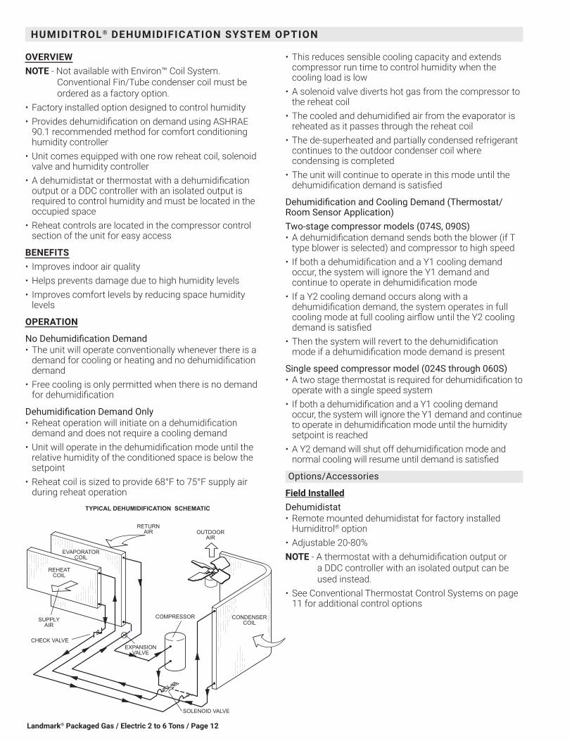
TYPICAL DEHUMIDIFICATION SCHEMATIC
REHEATCOIL
EVAPORATORCOIL
SOLENOID VALVE
RETURNAIR
CONDENSERCOIL
OUTDOORAIR
COMPRESSORSUPPLYAIR
CHECK VALVEEXPANSION
VALVE
HUMIDITROL ® DEHUMIDIFICATION SYSTEM OPTION
• This reduces sensible cooling capacity and extends compressor run time to control humidity when the cooling load is low
• A solenoid valve diverts hot gas from the compressor to the reheat coil
• The cooled and dehumidified air from the evaporator is reheated as it passes through the reheat coil
• The de-superheated and partially condensed refrigerant continues to the outdoor condenser coil where condensing is completed
• The unit will continue to operate in this mode until the dehumidification demand is satisfied
Dehumidification and Cooling Demand (Thermostat/Room Sensor Application)Two-stage compressor models (074S, 090S)• A dehumidification demand sends both the blower (if T
type blower is selected) and compressor to high speed• If both a dehumidification and a Y1 cooling demand
occur, the system will ignore the Y1 demand and continue to operate in dehumidification mode
• If a Y2 cooling demand occurs along with a dehumidification demand, the system operates in full cooling mode at full cooling airflow until the Y2 cooling demand is satisfied
• Then the system will revert to the dehumidification mode if a dehumidification mode demand is present
Single speed compressor model (024S through 060S)• A two stage thermostat is required for dehumidification to
operate with a single speed system• If both a dehumidification and a Y1 cooling demand
occur, the system will ignore the Y1 demand and continue to operate in dehumidification mode until the humidity setpoint is reached
• A Y2 demand will shut off dehumidification mode and normal cooling will resume until demand is satisfied
Options/Accessories
Field InstalledDehumidistat• Remote mounted dehumidistat for factory installed
Humiditrol® option• Adjustable 20-80%NOTE - A thermostat with a dehumidification output or
a DDC controller with an isolated output can be used instead.
• See Conventional Thermostat Control Systems on page 11 for additional control options

Landmark® Packaged Gas / Electric 2 to 6 Tons/ Page 13
OPTIONS / ACCESSORIES
Item Catalog No.
Unit Model No.KGB 024
KGB 030
KGB 036
KGB 048
KGB 060
KGB 072
KGB 074
KGB 090
COOLING SYSTEM
Condensate Drain Trap PVC 22H54 X X X X X X X XCopper 76W27 X X X X X X X X
Conventional Fin/Tube Condenser Coil (replaces Environ™ Coil System) Factory O O O O O ¹ O ODrain Pan Overflow Switch 74W42 X X X X X X X XLow Ambient Kit 14D89 X X X X X X X XEfficiency High O O O
Standard O O O O O O ORefrigerant Type R-410A O O O O O O O O
HEATING SYSTEM
Bottom Gas Piping Kit 19W50 X X X X X X X XLow Temperature Vestibule Heater
208/230V-1 or 3 ph 19W53 X X X X X X X X460V-3ph 19W54 X X X X X X575V-3ph 19W62 X X X X X X
Combustion Air Intake Extensions 19W51 X X X X X X X XGas Heat Input Standard One-Stage - 65 kBtuh input Factory O O O O 3 O O O
Standard Two-Stage - 53/70 kBtuh input Factory 2 O 2 O O 2 O 2 OMedium One-Stage - 108 kBtuh input Factory O O 3 O O O O
Medium Two Stage - 81/108 kBtuh input Factory O O O O O OHigh One-Stage - 150 kBtuh input Factory ³ O 3 O O O O
High Two-Stage - 113/150 kBtuh input Factory ³ O O O O OLPG/Propane Conversion Kits
For one-stage models 21Z22 X X X X X X X XFor two-stage models 21Z23 X X X X X X
Stainless Steel Heat Exchanger Factory O O O O O O O OVertical Vent Extension 31W62 X X X X X X X X1 074S models only.2 Standard Two-Stage Heat is only available with Low NOx Models.3 Three-Phase models only.
NOTE - The catalog numbers that appear here are for ordering field installed accessories only.OX - Field Installed or Configure to Order (Factory Installed)O - Configure to Order (Factory Installed)X - Field Installed
Landmark® Packaged Gas / Electric 2 to 6 Tons / Page 14
OPTIONS / ACCESSORIES
Item Catalog No.
Unit Model No.KGB 024
KGB 030
KGB 036
KGB 048
KGB 060
KGB 072
KGB 074
KGB 090
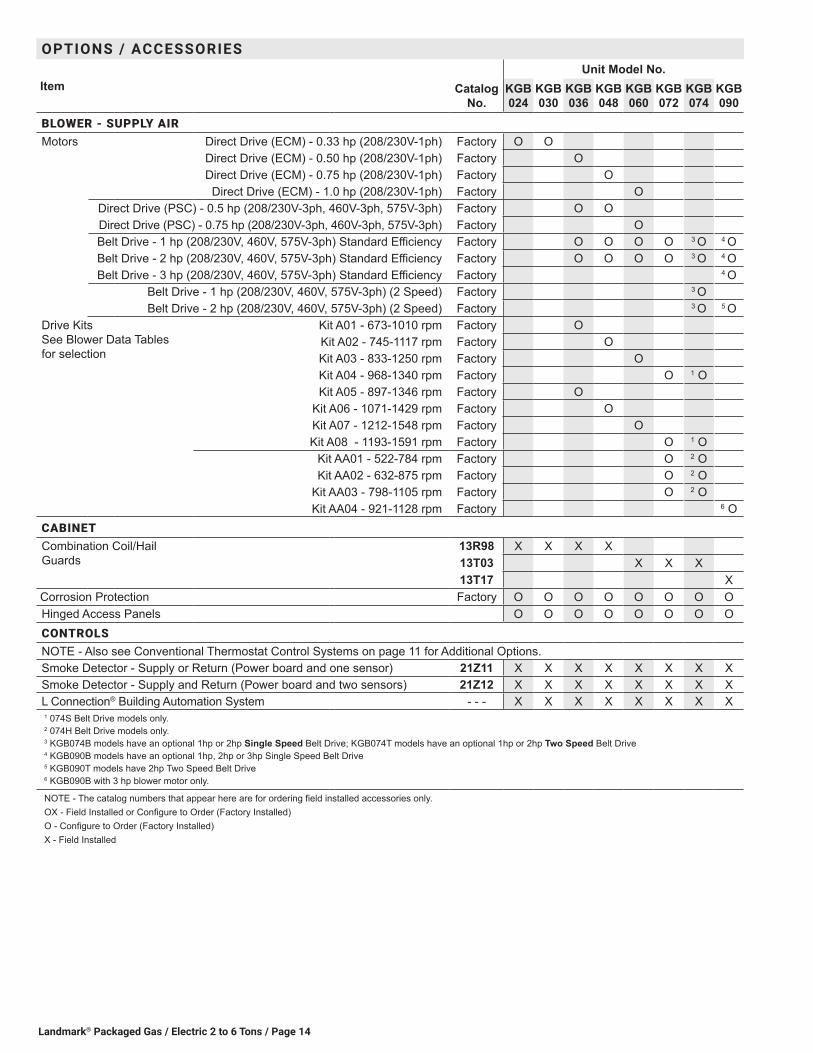
BLOWER - SUPPLY AIRMotors Direct Drive (ECM) - 0.33 hp (208/230V-1ph) Factory O O
Direct Drive (ECM) - 0.50 hp (208/230V-1ph) Factory ODirect Drive (ECM) - 0.75 hp (208/230V-1ph) Factory O
Direct Drive (ECM) - 1.0 hp (208/230V-1ph) Factory ODirect Drive (PSC) - 0.5 hp (208/230V-3ph, 460V-3ph, 575V-3ph) Factory O ODirect Drive (PSC) - 0.75 hp (208/230V-3ph, 460V-3ph, 575V-3ph) Factory OBelt Drive - 1 hp (208/230V, 460V, 575V-3ph) Standard Efficiency Factory O O O O 3 O 4 OBelt Drive - 2 hp (208/230V, 460V, 575V-3ph) Standard Efficiency Factory O O O O 3 O 4 OBelt Drive - 3 hp (208/230V, 460V, 575V-3ph) Standard Efficiency Factory 4 O
Belt Drive - 1 hp (208/230V, 460V, 575V-3ph) (2 Speed) Factory 3 OBelt Drive - 2 hp (208/230V, 460V, 575V-3ph) (2 Speed) Factory 3 O 5 O
Drive Kits See Blower Data Tables for selection
Kit A01 - 673-1010 rpm Factory OKit A02 - 745-1117 rpm Factory OKit A03 - 833-1250 rpm Factory OKit A04 - 968-1340 rpm Factory O 1 OKit A05 - 897-1346 rpm Factory O
Kit A06 - 1071-1429 rpm Factory OKit A07 - 1212-1548 rpm Factory OKit A08 - 1193-1591 rpm Factory O 1 O
Kit AA01 - 522-784 rpm Factory O 2 OKit AA02 - 632-875 rpm Factory O 2 O
Kit AA03 - 798-1105 rpm Factory O 2 OKit AA04 - 921-1128 rpm Factory 6 O
CABINETCombination Coil/Hail Guards
13R98 X X X X13T03 X X X13T17 X
Corrosion Protection Factory O O O O O O O OHinged Access Panels O O O O O O O OCONTROLSNOTE - Also see Conventional Thermostat Control Systems on page 11 for Additional Options.Smoke Detector - Supply or Return (Power board and one sensor) 21Z11 X X X X X X X XSmoke Detector - Supply and Return (Power board and two sensors) 21Z12 X X X X X X X XL Connection® Building Automation System - - - X X X X X X X X1 074S Belt Drive models only.2 074H Belt Drive models only.3 KGB074B models have an optional 1hp or 2hp Single Speed Belt Drive; KGB074T models have an optional 1hp or 2hp Two Speed Belt Drive4 KGB090B models have an optional 1hp, 2hp or 3hp Single Speed Belt Drive5 KGB090T models have 2hp Two Speed Belt Drive6 KGB090B with 3 hp blower motor only.
NOTE - The catalog numbers that appear here are for ordering field installed accessories only.OX - Field Installed or Configure to Order (Factory Installed)O - Configure to Order (Factory Installed)X - Field Installed

Landmark® Packaged Gas / Electric 2 to 6 Tons/ Page 15
OPTIONS / ACCESSORIES
Item Catalog No.
Unit Model No.KGB 024
KGB 030
KGB 036
KGB 048
KGB 060
KGB 072
KGB 074
KGB 090
ECONOMIZERStandard Economizer With Outdoor Air Hood (Sensible Control) (Not for Title 24)Standard Economizer Includes Barometric Relief Dampers and Exhaust Hood
14D90 OX OX OX OX OX OX OX OX
Standard Economizer - No Exhaust Factory O O O O O O O XStandard Economizer Controls (Not for Title 24)Single Enthalpy Control 21Z09 OX OX OX OX OX OX OX OXDifferential Enthalpy Control (order 2) 21Z09 X X X X X X X XHigh Performance Economizer With Outdoor Air Hood (Sensible Control) (Approved for California Title 24 Building Standards / AMCA Class 1A Certified)High Performance Economizer Includes Barometric Relief Dampers and Exhaust Hood
20H49 OX OX OX OX OX OX OX OX
High Performance Economizer Controls (Not for Title 24)Single Enthalpy Control 10Z75 OX OX OX OX OX OX OX OXDifferential Enthalpy Control (order 2) 10Z75 X X X X X X X XEconomizer AccessoriesHorizontal Economizer Conversion Kit 17W45 X X X X X X X XPOWER EXHAUST FANStandard StaticNOTE - Field installed Power Exhaust Fan requires “Barometric Relief Dampers for Power Exhaust Kit” for field installation. See below.
208/230V-1 or 3ph 21Z13 X X X X X X
460V-3ph 21Z14 X X X X X X
575V-3ph 21Z15 X X X X X X
1 BAROMETRIC RELIEF1 Barometric Relief Dampers for Power Exhaust Kit 21Z21 X X X X X X² Horizontal Barometric Relief Dampers With Exhaust Hood 19F01 X X X X X X X XOUTDOOR AIROutdoor Air Dampers With Outdoor Air HoodMotorized 15D17 OX OX OX OX OX OX OX OXManual 15D18 OX OX OX OX OX OX OX OXHUMIDITROL® CONDENSER REHEAT OPTIONHumiditrol Dehumidification Option, includes remote mounted Dehumidistat Factory O O O O O ⁴ O O³ Dehumidistat, Remote Mounted 99N41 X X X X X ⁴ X XELECTRICALVoltage 60 hz
208/230V - 1 phase O O O O O208/230V - 3 phase O O O O O O
460V - 3 phase O O O O O O575V - 3 phase O O O O O O
Disconnect See Electrical Data Tables for selection OX OX OX OX OX OX OX OXGFI Service Outlets
15 amp non-powered, field-wired (208/230V, 460V only) 74M70 OX OX OX OX OX OX OX OX20 amp non-powered, field-wired (575V only) 67E01 X X X X X X X X
Weatherproof Cover for GFI 10C89 X X X X X X X X1 Required when Economizer is factory installed with field installed Power Exhaust Fan option.2 Required when Economizer is configured for horizontal airflow.3 A thermostat with a dehumidification output or a DDC controller with an isolated output can be used instead.4 074S models only.
NOTE - The catalog numbers that appear here are for ordering field installed accessories only.OX - Field Installed or Configure to Order (Factory Installed)O - Configure to Order (Factory Installed)X - Field Installed
Landmark® Packaged Gas / Electric 2 to 6 Tons / Page 16
OPTIONS / ACCESSORIES
Item Catalog No.
Unit Model No.KGB 024
KGB 030
KGB 036
KGB 048
KGB 060
KGB 072
KGB 074
KGB 090
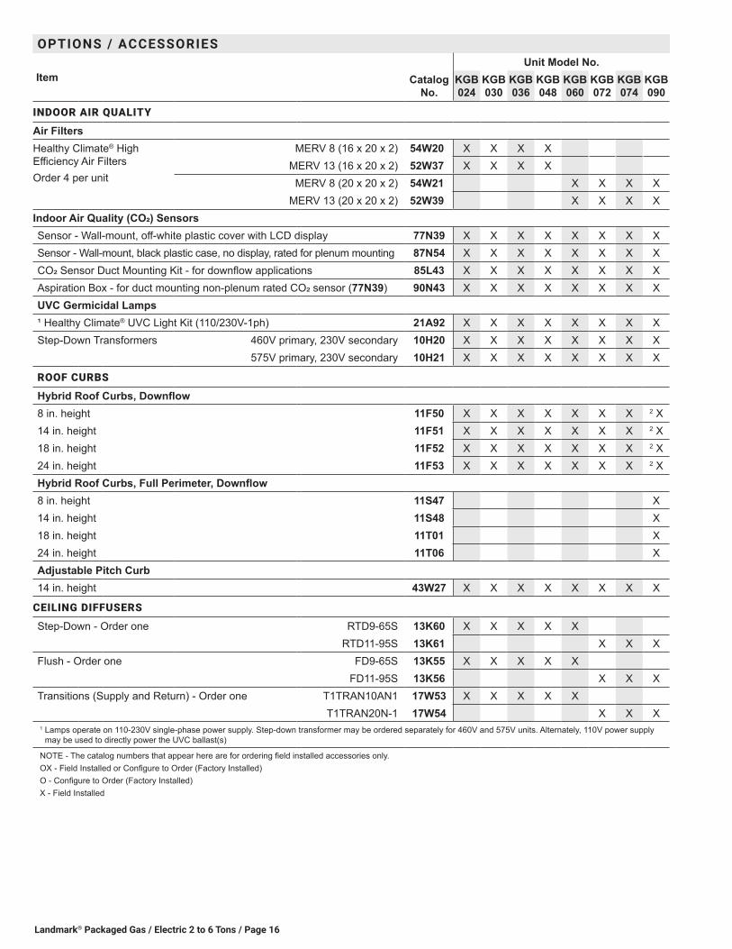
INDOOR AIR QUALITY
Air FiltersHealthy Climate® High Efficiency Air FiltersOrder 4 per unit
MERV 8 (16 x 20 x 2) 54W20 X X X XMERV 13 (16 x 20 x 2) 52W37 X X X X
MERV 8 (20 x 20 x 2) 54W21 X X X XMERV 13 (20 x 20 x 2) 52W39 X X X X
Indoor Air Quality (CO2) SensorsSensor - Wall-mount, off-white plastic cover with LCD display 77N39 X X X X X X X XSensor - Wall-mount, black plastic case, no display, rated for plenum mounting 87N54 X X X X X X X XCO2 Sensor Duct Mounting Kit - for downflow applications 85L43 X X X X X X X XAspiration Box - for duct mounting non-plenum rated CO2 sensor (77N39) 90N43 X X X X X X X XUVC Germicidal Lamps¹ Healthy Climate® UVC Light Kit (110/230V-1ph) 21A92 X X X X X X X XStep-Down Transformers 460V primary, 230V secondary 10H20 X X X X X X X X
575V primary, 230V secondary 10H21 X X X X X X X X
ROOF CURBS
Hybrid Roof Curbs, Downflow8 in. height 11F50 X X X X X X X 2 X14 in. height 11F51 X X X X X X X 2 X18 in. height 11F52 X X X X X X X 2 X24 in. height 11F53 X X X X X X X 2 XHybrid Roof Curbs, Full Perimeter, Downflow8 in. height 11S47 X14 in. height 11S48 X18 in. height 11T01 X24 in. height 11T06 XAdjustable Pitch Curb14 in. height 43W27 X X X X X X X X
CEILING DIFFUSERS
Step-Down - Order one RTD9-65S 13K60 X X X X XRTD11-95S 13K61 X X X
Flush - Order one FD9-65S 13K55 X X X X XFD11-95S 13K56 X X X
Transitions (Supply and Return) - Order one T1TRAN10AN1 17W53 X X X X XT1TRAN20N-1 17W54 X X X
1 Lamps operate on 110-230V single-phase power supply. Step-down transformer may be ordered separately for 460V and 575V units. Alternately, 110V power supply may be used to directly power the UVC ballast(s)
NOTE - The catalog numbers that appear here are for ordering field installed accessories only.OX - Field Installed or Configure to Order (Factory Installed)O - Configure to Order (Factory Installed)X - Field Installed
Landmark® Packaged Gas / Electric 2 to 6 Tons/ Page 17
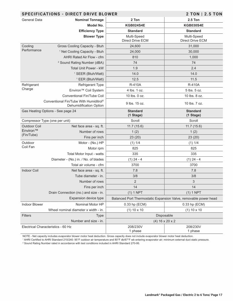
SPECIFICATIONS - DIRECT DRIVE BLOWER 2 TON | 2.5 TONGeneral Data Nominal Tonnage 2 Ton 2.5 Ton
Model No. KGB024S4E KGB030S4EEfficiency Type Standard Standard
Blower Type Multi-Speed Direct Drive ECM
Multi-Speed Direct Drive ECM
Cooling Performance
Gross Cooling Capacity - Btuh 24,600 31,0001 Net Cooling Capacity - Btuh 24,000 30,000
AHRI Rated Air Flow - cfm 810 1,0002 Sound Rating Number (dBA) 74 74
Total Unit Power - kW 1.9 2.41 SEER (Btuh/Watt) 14.0 14.0
1 EER (Btuh/Watt) 12.5 11.5Refrigerant Charge
Refrigerant Type R-410A R-410AEnviron™ Coil System 4 lbs. 1 oz. 5 lbs. 5 oz.
Conventional Fin/Tube Coil 10 lbs. 0 oz. 10 lbs. 8 oz.Conventional Fin/Tube With Humiditrol®
Dehumidification Option 9 lbs. 15 oz. 10 lbs. 7 oz.
Gas Heating Options - See page 24 Standard (1 Stage)
Standard (1 Stage)
Compressor Type (one per unit) Scroll ScrollOutdoor Coil Environ™ (Fin/Tube)
Net face area - sq. ft. 11.7 (15.6) 11.7 (15.6)Number of rows 1 (2) 1 (2)
Fins per inch 23 (20) 23 (20)Outdoor Coil Fan
Motor - (No.) HP (1) 1/4 (1) 1/4Motor rpm 825 825
Total Motor Input - watts 335 335Diameter - (No.) in. / No. of blades (1) 24 - 4 (1) 24 - 4
Total air volume - cfm 3700 3700Indoor Coil Net face area - sq. ft. 7.8 7.8
Tube diameter - in. 3/8 3/8Number of rows 2 3
Fins per inch 14 14Drain Connection (no.) and size - in. (1) 1 NPT (1) 1 NPT
Expansion device type Balanced Port Thermostatic Expansion Valve, removable power head
Indoor Blower Nominal Motor HP 0.33 hp (ECM) 0.33 hp (ECM)Wheel nominal diameter x width - in. (1) 10 x 10 (1) 10 x 10
Filters Type DisposableNumber and size - in. (4) 16 x 20 x 2
Electrical Characteristics - 60 Hz 208/230V 1 phase
208/230V 1 phase
NOTE - Net capacity includes evaporator blower motor heat deduction. Gross capacity does not include evaporator blower motor heat deduction.1 AHRI Certified to AHRI Standard 210/240: 95°F outdoor air temperature and 80°F db/67°F wb entering evaporator air; minimum external duct static pressure.2 Sound Rating Number rated in accordance with test conditions included in AHRI Standard 270-95.

Landmark® Packaged Gas / Electric 2 to 6 Tons / Page 18
SPECIFICATIONS - DIRECT DRIVE BLOWER 3 TON | 4 TONGeneral Data Nominal Tonnage 3 Ton 3 Ton 4 Ton 4 Ton
Model No. KGB036S4E KGB036S4D KGB048S4E KGB048S4DEfficiency Type Standard Standard Standard Standard
Blower Type Multi-Speed Direct Drive
ECM
Multi-Speed Direct Drive
PSC
Multi-Speed Direct Drive
ECM
Multi-Speed Direct Drive
PSCCooling Performance
Gross Cooling Capacity - Btuh 37,300 37,300 49,700 49,7001 Net Cooling Capacity - Btuh 36,000 36,000 47,500 47,500
AHRI Rated Air Flow - cfm 1150 1150 1560 15602 Sound Rating Number (dBA) 74 74 74 74
Total Unit Power - kW 2.9 2.9 4.1 4.11 SEER (Btuh/Watt) 14.0 14.0 14.0 14.0
1 EER (Btuh/Watt) 12.3 12.3 11.5 11.5Refrigerant Charge
Refrigerant Type R-410A R-410A R-410A R-410AEnviron™ Coil System 5 lbs. 9 oz. 5 lbs. 9 oz. 5 lbs. 10 oz. 5 lbs. 10 oz.
Conventional Fin/Tube Coil 11 lbs. 3 oz. 11 lbs. 3 oz. 9 lbs. 13 oz. 9 lbs. 13 oz.Conventional Fin/Tube With Humiditrol®
Dehumidification Option 12 lbs. 7 oz. 12 lbs. 7 oz. 9 lbs. 13 oz. 9 lbs. 13 oz.
Gas Heating Options - See page 24 Standard (1 or 2 Stage) Medium (1 or 2 Stage)
Standard (1 or 2 Stage) Medium (1 or 2 Stage)
High (1 or 2 Stage)Compressor Type (one per unit) Scroll Scroll Scroll ScrollOutdoor Coil Environ™ (Fin/Tube)
Net face area - sq. ft. 14.5 (15.6) 14.5 (15.6) 14.5 (15.6) 14.5 (15.6)Number of rows 1 (2) 1 (2) 1 (2) 1 (2)
Fins per inch 23 (20) 23 (20) 23 (20) 23 (20)Outdoor Coil Fan
Motor - (No.) HP (1) 1/4 (1) 1/4 (1) 1/4 (1) 1/4Motor rpm 825 825 825 825
Total Motor Input - watts 325 325 325 325Diameter - (No.) in. / No. of blades (1) 24 - 4 (1) 24 - 4 (1) 24 - 4 (1) 24 - 4
Total air volume - cfm 3950 3950 3950 3950Indoor Coil Net face area - sq. ft. 7.8 7.8 7.8 7.8
Tube diameter - in. 3/8 3/8 3/8 3/8Number of rows 3 3 3 3
Fins per inch 14 14 14 14Drain Connection (no.) and size - in. (1) 1 NPT (1) 1 NPT (1) 1 NPT (1) 1 NPT
Expansion device type Balanced Port Thermostatic Expansion Valve, removable power headIndoor Blower
Nominal Motor HP 0.50 hp (ECM) 0.50 hp (PSC) 0.75 hp (ECM) 0.50 hp (PSC)Wheel nominal diameter x width - in. (1) 10 x 10 (1) 10 x 10 (1) 10 x 10 (1) 10 x 10
Filters Type DisposableNumber and size - in. (4) 16 x 20 x 2
Electrical Characteristics - 60 Hz 208/230V 1 phase
208/230V, 460V & 575V
3 phase
208/230V 1 phase
208/230V, 460V & 575V
3 phaseNOTE - Net capacity includes evaporator blower motor heat deduction. Gross capacity does not include evaporator blower motor heat deduction.1 AHRI Certified to AHRI Standard 210/240: 95°F outdoor air temperature and 80°F db/67°F wb entering evaporator air; minimum external duct static pressure.2 Sound Rating Number rated in accordance with test conditions included in AHRI Standard 270-95.

Landmark® Packaged Gas / Electric 2 to 6 Tons/ Page 19
SPECIFICATIONS - DIRECT DRIVE BLOWER 5 TONGeneral Data Nominal Tonnage 5 Ton 5 Ton
Model No. KGB060S4E KGB060S4DEfficiency Type Standard Standard
Blower Type Multi-Speed Direct Drive ECM
Multi-Speed Direct Drive PSC
Cooling Performance
Gross Cooling Capacity - Btuh 60,900 60,9001 Net Cooling Capacity - Btuh 58,500 58,500
AHRI Rated Air Flow - cfm 1760 17602 Sound Rating Number (dBA) 83 83
Total Unit Power - kW 5.0 5.01 SEER (Btuh/Watt) 14.0 14.0
1 EER (Btuh/Watt) 11.0 11.0Refrigerant Charge
Refrigerant Type R-410A R-410AEnviron™ Coil System 8 lbs. 0 oz. 8 lbs. 0 oz.
Conventional Fin/Tube Coil 14 lbs. 3 oz. 14 lbs. 3 oz.Conventional Fin/Tube With Humiditrol® Dehumidification
Option 15 lbs. 3 oz. 15 lbs. 3 oz.
Gas Heating Options - See page 24 Standard (2 Stage) Medium (2 Stage)
High (2 Stage)
Standard (1 or 2 Stage) Medium (1 or 2 Stage)
High (1 or 2 Stage)Compressor Type (one per unit) Scroll ScrollOutdoor Coil Environ™ (Fin/Tube)
Net face area - sq. ft. 17.8 (19.3) 17.8 (19.3)Number of rows 1 (2) 1 (2)
Fins per inch 23 (20) 23 (20)Outdoor Coil Fan
Motor - (No.) HP (1) 1/3 (1) 1/3Motor rpm 1075 1075
Total Motor Input - watts 375 375Diameter - (No.) in. / No. of blades (1) 24 - 3 (1) 24 - 3
Total air volume - cfm 4700 4700Indoor Coil Net face area - sq. ft. 9.7 9.7
Tube diameter - in. 3/8 3/8Number of rows 4 4
Fins per inch 14 14Drain Connection (no.) and size - in. (1) 1 NPT (1) 1 NPT
Expansion device type Balanced Port Thermostatic Expansion Valve, removable power headIndoor Blower
Nominal Motor HP 1 hp (ECM) 0.75 hp (PSC)Wheel nominal diameter x width - in. (1) 11 x 10 (1) 11 x 10
Filters Type DisposableNumber and size - in. (4) 20 x 20 x 2
Electrical Characteristics - 60 Hz 208/230V 1 phase
208/230V, 460V & 575V
3 phaseNOTE - Net capacity includes evaporator blower motor heat deduction. Gross capacity does not include evaporator blower motor heat deduction.1 AHRI Certified to AHRI Standard 210/240: 95°F outdoor air temperature and 80°F db/67°F wb entering evaporator air; minimum external duct static pressure.2 Sound Rating Number rated in accordance with test conditions included in AHRI Standard 270-95.

Landmark® Packaged Gas / Electric 2 to 6 Tons / Page 20
SPECIFICATIONS - BELT DRIVE BLOWER SINGLE SPEED - 3 TON | 4 TON | 5 TONGeneral Data Nominal Tonnage 3 Ton 4 Ton 5 Ton
Model No. KGB036S4B KGB048S4B KGB060S4BEfficiency Type Standard Standard Standard
Blower Type Single Speed Belt Drive
Single Speed Belt Drive
Single Speed Belt Drive
Cooling Performance
Gross Cooling Capacity - Btuh 37,300 49,700 60,9001 Net Cooling Capacity - Btuh 36,000 47,500 58,500
AHRI Rated Air Flow - cfm 1150 1560 17602 Sound Rating Number (dBA) 74 74 83
Total Unit Power - kW 2.9 4.1 51 SEER (Btuh/Watt) 14.0 14.0 14.0
1 EER (Btuh/Watt) 12.3 11.5 11.0Refrigerant Charge
Refrigerant Type R-410A R-410A R-410AEnviron™ Coil System 5 lbs. 9 oz. 5 lbs. 10 oz. 8 lbs. 0 oz.
Conventional Fin/Tube Coil 11 lbs. 3 oz. 9 lbs. 13 oz. 14 lbs. 3 oz.Conventional Fin/Tube With Humiditrol® Dehumidification Option 12 lbs. 7 oz. 9 lbs. 13 oz. 15 lbs. 3 oz.Gas Heating Options - See page 24 Standard (1 or 2 Stage)
Medium (1 or 2 Stage)
Standard (1 or 2 Stage) Medium (1 or 2 Stage)
High (1 or 2 Stage)Compressor Type (one per unit) Scroll Scroll ScrollOutdoor Coil Environ™ (Fin/Tube)
Net face area - sq. ft. 14.5 (15.6) 14.5 (15.6) 17.8 (19.3)Number of rows 1 (2) 1 (2) 1 (2)
Fins / inch 23 (20) 23 (20) 23 (20)Outdoor Coil Fan
Motor - (No.) HP (1) 1/4 (1) 1/4 (1) 1/3Motor rpm 825 825 1075
Total Motor Input - watts 325 325 375Diameter - (No.) in. / No. of blades (1) 24 - 4 (1) 24 - 4 (1) 24 - 3
Total air volume - cfm 3950 3950 4700Indoor Coil Net face area - sq. ft. 7.8 7.8 9.7
Tube diameter - in. 3/8 3/8 3/8Number of rows 3 3 4
Fins per inch 14 14 14Drain Connection (no.) and size - in. (1) 1 NPT (1) 1 NPT (1) 1 NPT
Expansion device type Balanced Port Thermostatic Expansion Valve, removable power head3 Indoor
Blower & Drive Selection
Nominal Motor HP 1 hp, 2 hp 1 hp, 2 hp 1 hp, 2 hpMaximum Usable Motor Output (US Only) 1.15 hp, 2.3 hp 1.15 hp, 2.3 hp 1.15 hp, 2.3 hp
Available Drive Kits A01 673 - 1010 rpm
A05 897 - 1346 rpm
A02 745 - 1117 rpm
A06 1071 - 1429 rpm
A03 833 - 1250 rpm
A07 1212 - 1548 rpm
Wheel nominal diameter x width - in. (1) 10 x 10 (1) 10 x 10 (1) 10 x 10Filters Type Disposable
Number and size - in. (4) 16 x 20 x 2 (4) 20 x 20 x 2Electrical Characteristics - 60 Hz 208/230V, 460V or 575V − 60 hertz − 3 phaseNOTE - Net capacity includes evaporator blower motor heat deduction. Gross capacity does not include evaporator blower motor heat deduction.1 AHRI Certified to AHRI Standard 210/240: 95°F outdoor air temperature and 80°F db/67°F wb entering evaporator air; minimum external duct static pressure.2 Sound Rating Number rated in accordance with test conditions included in AHRI Standard 270-95.3 Using total air volume and system static pressure requirements determine from blower performance tables rpm and motor hp required. Maximum usable hp of motors
furnished are shown. In Canada, nominal motor hp is also maximum usable motor hp output. If motors of comparable hp are used, be sure to keep within the service factor limitations outlined on the motor nameplate.

Landmark® Packaged Gas / Electric 2 to 6 Tons/ Page 21
SPECIFICATIONS - BELT DRIVE BLOWER SINGLE SPEED - 6 TONGeneral Data Nominal Tonnage 6 Ton 6 Ton
Model No. KGB072H4B KGB074S4BEfficiency Type High Standard
Blower Type Single Speed Belt Drive Single Speed Belt DriveCooling Performance
Gross Cooling Capacity - Btuh 73,500 71,0001 Net Cooling Capacity - Btuh 72,000 68,000
AHRI Rated Air Flow - cfm 1920 21502 Sound Rating Number (dBA) 79 79
Total Unit Power - kW 6.0 6.11 IEER 13.5 12.7
1 EER (Btuh/Watt) 12.0 11.0Refrigerant Charge
Refrigerant Type R-410A R-410AEnviron™ Coil System 7 lbs. 8 oz. 7 lbs. 2 oz.
Conventional Fin/Tube Coil - - - 14 lbs. 8 oz.Conventional Fin/Tube With Humiditrol® Dehumidification Option - - - 14 lbs. 11 oz.Gas Heating Options - See page 24 Standard (1 or 2 Stage)
Medium (1 or 2 Stage) High (1 or 2 Stage)
Standard (1 Stage) Medium (1 or 2 Stage)
High (1 or 2 Stage)Compressor Type (one per unit) Scroll Two-Stage ScrollOutdoor Coil Environ™ (Fin/Tube)
Net face area - sq. ft. 17.8 17.8 (19.3)Number of rows 1 1 (2)
Fins / inch 23 23 (20)Outdoor Coil Fan
Motor - (No.) HP (1) 1/3 (1) 1/3Motor rpm 1075 1075
Total Motor Input - watts 410 375Diameter - (No.) in. / No. of blades (1) 24 - 3 (1) 24 - 3
Total air volume - cfm 4800 4700Indoor Coil Net face area - sq. ft. 9.72 9.72
Tube diameter - in. 3/8 3/8Number of rows 4 4
Fins per inch 14 14Drain Connection (no.) and size - in. (1) 1 NPT (1) 1 in. NPT
Expansion device type Balanced Port Thermostatic Expansion Valve, removable power head3 Indoor
Blower & Drive Selection
Nominal Motor Output 1 hp, 2 hp 1 hp, 2 hpMaximum Usable Motor Output (US Only) 1.15 hp, 2.3 hp 1.15 hp 2.3 hp
Motor - Drive Kit Number AA01 522-784 rpm
AA02 632-875 rpm
AA03 798-1105 rpm
A04968 - 1340 rpm
A081193-1591 rpm
Wheel Nominal Diameter x Width - in. (1) 15 x 9 10 X 10Filters Type Disposable Disposable
Number and size - in. (4) 20 x 20 x 2 (4) 20 x 20 x 2Electrical Characteristics - 60 Hz 208/230V, 460V or 575V − 60 hertz − 3 phaseNOTE - Net capacity includes evaporator blower motor heat deduction. Gross capacity does not include evaporator blower motor heat deduction.1 AHRI Certified to AHRI Standard 340/360: 95°F outdoor air temperature and 80°F db/67°F wb entering evaporator air; minimum external duct static pressure.2 Sound Rating Number rated in accordance with test conditions included in AHRI Standard 270-95.3 Using total air volume and system static pressure requirements determine from blower performance tables rpm and motor hp required. Maximum usable hp of motors
furnished are shown. In Canada, nominal motor hp is also maximum usable motor hp output. If motors of comparable hp are used, be sure to keep within the service factor limitations outlined on the motor nameplate.
Landmark® Packaged Gas / Electric 2 to 6 Tons / Page 22
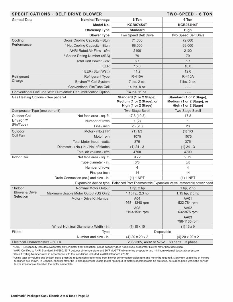
SPECIFICATIONS - BELT DRIVE BLOWER TWO-SPEED - 6 TONGeneral Data Nominal Tonnage 6 Ton 6 Ton
Model No. KGB074S4T KGB074H4TEfficiency Type Standard High
Blower Type Two Speed Belt Drive Two Speed Belt DriveCooling Performance
Gross Cooling Capacity - Btuh 71,000 72,0001 Net Cooling Capacity - Btuh 68,000 69,000
AHRI Rated Air Flow - cfm 2100 21002 Sound Rating Number (dBA) 79 79
Total Unit Power - kW 6.1 5.71 IEER 15.0 16.0
1 EER (Btuh/Watt) 11.2 12.0Refrigerant Charge
Refrigerant Type R-410A R-410AEnviron™ Coil System 7 lbs. 2 oz. 7 lbs. 2 oz.
Conventional Fin/Tube Coil 14 lbs. 8 oz. - - -Conventional Fin/Tube With Humiditrol® Dehumidification Option 14 lbs. 11 oz. - - -Gas Heating Options - See page 24 Standard (1 or 2 Stage),
Medium (1 or 2 Stage), or High (1 or 2 Stage)
Standard (1 or 2 Stage), Medium (1 or 2 Stage), or
High (1 or 2 Stage)Compressor Type (one per unit) Two-Stage Scroll Two-Stage ScrollOutdoor Coil Environ™ (Fin/Tube)
Net face area - sq. ft. 17.8 (19.3) 17.8Number of rows 1 (2) 1
Fins / inch 23 (20) 23Outdoor Coil Fan
Motor - (No.) HP (1) 1/3 (1) 1/3Motor rpm 1075 1075
Total Motor Input - watts 375 375Diameter - (No.) in. / No. of blades (1) 24 - 3 (1) 24 - 3
Total air volume - cfm 4700 4700Indoor Coil Net face area - sq. ft. 9.72 9.72
Tube diameter - in. 3/8 3/8Number of rows 4 4
Fins per inch 14 14Drain Connection (no.) and size - in. (1) 1 NPT (1) 1 NPT
Expansion device type Balanced Port Thermostatic Expansion Valve, removable power head3 Indoor
Blower & Drive Selection
Nominal Motor Output 1 hp, 2 hp 1 hp, 2 hpMaximum Usable Motor Output (US Only) 1.15 hp, 2.3 hp 1.15 hp, 2.3 hp
Motor - Drive Kit Number A04 968 - 1340 rpm
A08 1193-1591 rpm
AA01 522-784 rpm
AA02 632-875 rpm
AA03 798-1105 rpm
Wheel Nominal Diameter x Width - in. (1) 10 x 10 (1) 15 x 9Filters Type Disposable
Number and size - in. (4) 20 x 20 x 2 (4) 20 x 20 x 2Electrical Characteristics - 60 Hz 208/230V, 460V or 575V − 60 hertz − 3 phaseNOTE - Net capacity includes evaporator blower motor heat deduction. Gross capacity does not include evaporator blower motor heat deduction.1 AHRI Certified to AHRI Standard 340/360: 95°F outdoor air temperature and 80°F db/67°F wb entering evaporator air; minimum external duct static pressure.2 Sound Rating Number rated in accordance with test conditions included in AHRI Standard 270-95.3 Using total air volume and system static pressure requirements determine from blower performance tables rpm and motor hp required. Maximum usable hp of motors
furnished are shown. In Canada, nominal motor hp is also maximum usable motor hp output. If motors of comparable hp are used, be sure to keep within the service factor limitations outlined on the motor nameplate.
Landmark® Packaged Gas / Electric 2 to 6 Tons/ Page 23
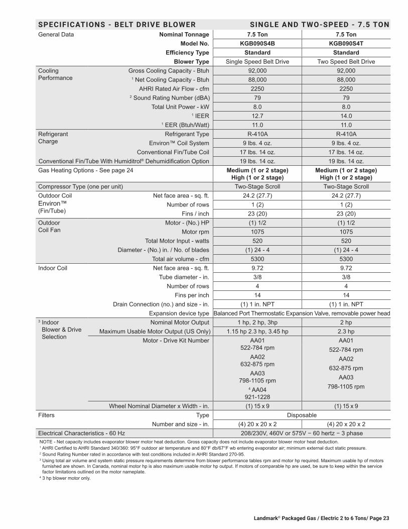
SPECIFICATIONS - BELT DRIVE BLOWER SINGLE AND TWO-SPEED - 7.5 TONGeneral Data Nominal Tonnage 7.5 Ton 7.5 Ton
Model No. KGB090S4B KGB090S4TEfficiency Type Standard Standard
Blower Type Single Speed Belt Drive Two Speed Belt DriveCooling Performance
Gross Cooling Capacity - Btuh 92,000 92,0001 Net Cooling Capacity - Btuh 88,000 88,000
AHRI Rated Air Flow - cfm 2250 22502 Sound Rating Number (dBA) 79 79
Total Unit Power - kW 8.0 8.01 IEER 12.7 14.0
1 EER (Btuh/Watt) 11.0 11.0Refrigerant Charge
Refrigerant Type R-410A R-410AEnviron™ Coil System 9 lbs. 4 oz. 9 lbs. 4 oz.
Conventional Fin/Tube Coil 17 lbs. 14 oz. 17 lbs. 14 oz.Conventional Fin/Tube With Humiditrol® Dehumidification Option 19 lbs. 14 oz. 19 lbs. 14 oz.Gas Heating Options - See page 24 Medium (1 or 2 stage)
High (1 or 2 stage)Medium (1 or 2 stage)
High (1 or 2 stage)Compressor Type (one per unit) Two-Stage Scroll Two-Stage ScrollOutdoor Coil Environ™ (Fin/Tube)
Net face area - sq. ft. 24.2 (27.7) 24.2 (27.7)Number of rows 1 (2) 1 (2)
Fins / inch 23 (20) 23 (20)Outdoor Coil Fan
Motor - (No.) HP (1) 1/2 (1) 1/2Motor rpm 1075 1075
Total Motor Input - watts 520 520Diameter - (No.) in. / No. of blades (1) 24 - 4 (1) 24 - 4
Total air volume - cfm 5300 5300Indoor Coil Net face area - sq. ft. 9.72 9.72
Tube diameter - in. 3/8 3/8Number of rows 4 4
Fins per inch 14 14Drain Connection (no.) and size - in. (1) 1 in. NPT (1) 1 in. NPT
Expansion device type Balanced Port Thermostatic Expansion Valve, removable power head3 Indoor
Blower & Drive Selection
Nominal Motor Output 1 hp, 2 hp, 3hp 2 hpMaximum Usable Motor Output (US Only) 1.15 hp 2.3 hp, 3.45 hp 2.3 hp
Motor - Drive Kit Number AA01 522-784 rpm
AA02 632-875 rpm
AA03 798-1105 rpm
4 AA04 921-1228
AA01522-784 rpm
AA02632-875 rpm
AA03798-1105 rpm
Wheel Nominal Diameter x Width - in. (1) 15 x 9 (1) 15 x 9Filters Type Disposable
Number and size - in. (4) 20 x 20 x 2 (4) 20 x 20 x 2Electrical Characteristics - 60 Hz 208/230V, 460V or 575V − 60 hertz − 3 phaseNOTE - Net capacity includes evaporator blower motor heat deduction. Gross capacity does not include evaporator blower motor heat deduction.1 AHRI Certified to AHRI Standard 340/360: 95°F outdoor air temperature and 80°F db/67°F wb entering evaporator air; minimum external duct static pressure.2 Sound Rating Number rated in accordance with test conditions included in AHRI Standard 270-95.3 Using total air volume and system static pressure requirements determine from blower performance tables rpm and motor hp required. Maximum usable hp of motors
furnished are shown. In Canada, nominal motor hp is also maximum usable motor hp output. If motors of comparable hp are used, be sure to keep within the service factor limitations outlined on the motor nameplate.
4 3 hp blower motor only.
Landmark® Packaged Gas / Electric 2 to 6 Tons / Page 24
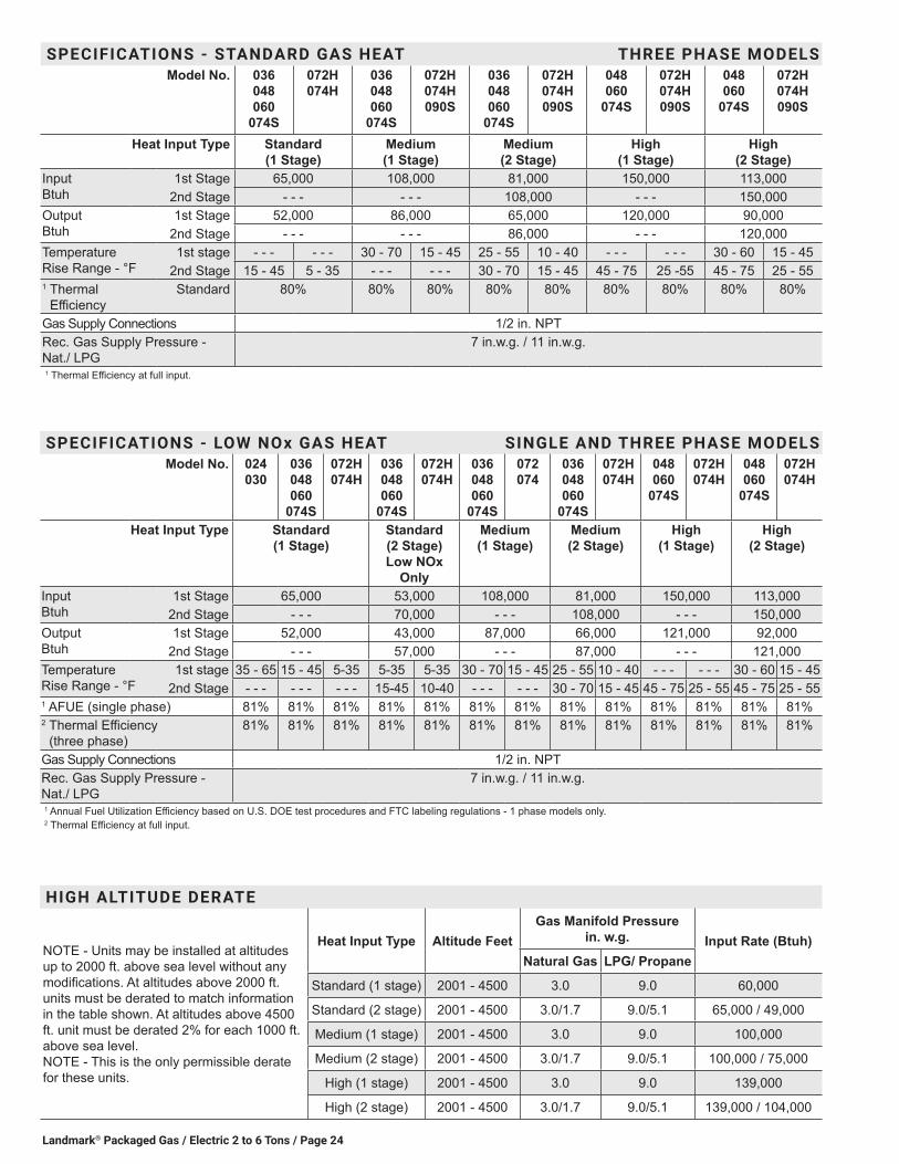
SPECIFICATIONS - LOW NOx GAS HEAT SINGLE AND THREE PHASE MODELSModel No. 024
030036 048 060
074S
072H 074H
036 048 060
074S
072H 074H
036 048 060
074S
072 074
036 048 060
074S
072H 074H
048 060
074S
072H 074H
048 060
074S
072H 074H
Heat Input Type Standard (1 Stage)
Standard (2 Stage) Low NOx
Only
Medium (1 Stage)
Medium (2 Stage)
High (1 Stage)
High (2 Stage)
Input Btuh
1st Stage 65,000 53,000 108,000 81,000 150,000 113,0002nd Stage - - - 70,000 - - - 108,000 - - - 150,000
Output Btuh
1st Stage 52,000 43,000 87,000 66,000 121,000 92,0002nd Stage - - - 57,000 - - - 87,000 - - - 121,000
Temperature Rise Range - °F
1st stage 35 - 65 15 - 45 5-35 5-35 5-35 30 - 70 15 - 45 25 - 55 10 - 40 - - - - - - 30 - 60 15 - 452nd Stage - - - - - - - - - 15-45 10-40 - - - - - - 30 - 70 15 - 45 45 - 75 25 - 55 45 - 75 25 - 55
1 AFUE (single phase) 81% 81% 81% 81% 81% 81% 81% 81% 81% 81% 81% 81% 81%2 Thermal Efficiency
(three phase)81% 81% 81% 81% 81% 81% 81% 81% 81% 81% 81% 81% 81%
Gas Supply Connections 1/2 in. NPTRec. Gas Supply Pressure - Nat./ LPG
7 in.w.g. / 11 in.w.g.
1 Annual Fuel Utilization Efficiency based on U.S. DOE test procedures and FTC labeling regulations - 1 phase models only.2 Thermal Efficiency at full input.
HIGH ALTITUDE DERATE
NOTE - Units may be installed at altitudes up to 2000 ft. above sea level without any modifications. At altitudes above 2000 ft. units must be derated to match information in the table shown. At altitudes above 4500 ft. unit must be derated 2% for each 1000 ft. above sea level. NOTE - This is the only permissible derate for these units.
Heat Input Type Altitude Feet Gas Manifold Pressure
in. w.g. Input Rate (Btuh) Natural Gas LPG/ Propane
Standard (1 stage) 2001 - 4500 3.0 9.0 60,000
Standard (2 stage) 2001 - 4500 3.0/1.7 9.0/5.1 65,000 / 49,000
Medium (1 stage) 2001 - 4500 3.0 9.0 100,000
Medium (2 stage) 2001 - 4500 3.0/1.7 9.0/5.1 100,000 / 75,000
High (1 stage) 2001 - 4500 3.0 9.0 139,000
High (2 stage) 2001 - 4500 3.0/1.7 9.0/5.1 139,000 / 104,000
SPECIFICATIONS - STANDARD GAS HEAT THREE PHASE MODELSModel No. 036
048 060
074S
072H 074H
036 048 060
074S
072H 074H 090S
036 048 060
074S
072H 074H 090S
048 060
074S
072H 074H 090S
048 060
074S
072H 074H 090S
Heat Input Type Standard (1 Stage)
Medium (1 Stage)
Medium (2 Stage)
High (1 Stage)
High (2 Stage)
Input Btuh
1st Stage 65,000 108,000 81,000 150,000 113,0002nd Stage - - - - - - 108,000 - - - 150,000
Output Btuh
1st Stage 52,000 86,000 65,000 120,000 90,0002nd Stage - - - - - - 86,000 - - - 120,000
Temperature Rise Range - °F
1st stage - - - - - - 30 - 70 15 - 45 25 - 55 10 - 40 - - - - - - 30 - 60 15 - 452nd Stage 15 - 45 5 - 35 - - - - - - 30 - 70 15 - 45 45 - 75 25 -55 45 - 75 25 - 55
1 Thermal Efficiency
Standard 80% 80% 80% 80% 80% 80% 80% 80% 80%
Gas Supply Connections 1/2 in. NPTRec. Gas Supply Pressure - Nat./ LPG
7 in.w.g. / 11 in.w.g.
1 Thermal Efficiency at full input.

Landmark® Packaged Gas / Electric 2 to 6 Tons/ Page 25
2 TON - KGB024S4Entering
Wet Bulb Tem-
perature
Total Air
Volume
Outdoor Air Temperature Entering Outdoor Coil85°F 95°F 105°F 115°F
Total Cool Cap.
Comp. Motor Input
Sensible To Total Ratio (S/T)
Total Cool Cap.
Comp. Motor Input
Sensible To Total Ratio (S/T)
Total Cool Cap.
Comp. Motor Input
Sensible To Total Ratio (S/T)
Total Cool Cap.
Comp. Motor Input
Sensible To Total Ratio (S/T)
Dry Bulb Dry Bulb Dry Bulb Dry Bulbcfm kBtuh kW 75°F 80°F 85°F kBtuh kW 75°F 80°F 85°F kBtuh kW 75°F 80°F 85°F kBtuh kW 75°F 80°F 85°F
63°F640 23.2 1.31 0.69 0.84 0.99 21.7 1.49 0.7 0.86 1 20.1 1.72 0.71 0.89 1 18.4 1.97 0.73 0.92 1800 24.6 1.3 0.75 0.93 1 23.1 1.48 0.76 0.95 1 21.4 1.7 0.78 0.98 1 19.7 1.95 0.8 1 1960 25.8 1.29 0.8 1 1 24.3 1.47 0.82 1 1 22.7 1.69 0.85 1 1 21 1.94 0.88 1 1
67°F640 24.5 1.3 0.54 0.67 0.81 23 1.48 0.54 0.68 0.82 21.4 1.71 0.54 0.69 0.85 19.7 1.96 0.54 0.71 0.88800 26.1 1.28 0.58 0.72 0.89 24.5 1.47 0.58 0.74 0.91 22.7 1.69 0.58 0.75 0.94 20.8 1.94 0.59 0.78 0.98960 27.2 1.27 0.61 0.78 0.96 25.5 1.45 0.61 0.8 0.99 23.7 1.68 0.62 0.82 1 21.6 1.93 0.63 0.86 1
71°F640 25.7 1.29 0.41 0.53 0.65 24.2 1.47 0.4 0.53 0.66 22.6 1.7 0.39 0.53 0.67 20.8 1.95 0.38 0.54 0.68800 27.4 1.27 0.42 0.57 0.7 25.8 1.45 0.42 0.57 0.72 24 1.68 0.41 0.58 0.73 22.1 1.93 0.39 0.58 0.76960 28.6 1.25 0.44 0.6 0.76 26.9 1.44 0.43 0.61 0.77 25 1.66 0.43 0.61 0.8 22.9 1.91 0.43 0.63 0.83
2.5 TON - KGB030S4Entering
Wet Bulb Tem-
perature
Total Air
Volume
Outdoor Air Temperature Entering Outdoor Coil85°F 95°F 105°F 115°F
Total Cool Cap.
Comp. Motor Input
Sensible To Total Ratio (S/T)
Total Cool Cap.
Comp. Motor Input
Sensible To Total Ratio (S/T)
Total Cool Cap.
Comp. Motor Input
Sensible To Total Ratio (S/T)
Total Cool Cap.
Comp. Motor Input
Sensible To Total Ratio (S/T)
Dry Bulb Dry Bulb Dry Bulb Dry Bulbcfm kBtuh kW 75°F 80°F 85°F kBtuh kW 75°F 80°F 85°F kBtuh kW 75°F 80°F 85°F kBtuh kW 75°F 80°F 85°F
63°F800 29.2 1.66 0.7 0.85 1 28.1 1.9 0.71 0.87 1 26.3 2.21 0.73 0.9 1 24.6 2.69 0.74 0.93 1
1000 30.7 1.66 0.76 0.95 1 29.5 1.9 0.77 0.97 1 27.7 2.21 0.79 1 1 26.1 2.69 0.81 1 11200 32 1.66 0.82 1 1 30.9 1.91 0.83 1 1 29.2 2.22 0.86 1 1 27.5 2.69 0.9 1 1
67°F800 30.9 1.66 0.55 0.68 0.82 29.7 1.91 0.55 0.69 0.83 27.9 2.22 0.56 0.7 0.86 26.2 2.69 0.56 0.72 0.89
1000 32.3 1.67 0.59 0.74 0.92 31.1 1.91 0.59 0.75 0.93 29.2 2.22 0.6 0.77 0.96 27.3 2.68 0.61 0.79 0.991200 33.3 1.67 0.6 0.8 1 32 1.92 0.62 0.81 1 30.1 2.22 0.63 0.84 1 28.2 2.7 0.65 0.87 1
71°F800 32.5 1.67 0.41 0.54 0.66 31.3 1.91 0.41 0.54 0.67 29.5 2.22 0.41 0.55 0.68 27.7 2.69 0.41 0.56 0.7
1000 33.9 1.67 0.44 0.58 0.73 32.6 1.92 0.43 0.58 0.73 30.7 2.23 0.43 0.59 0.75 28.8 2.69 0.43 0.59 0.771200 34.8 1.68 0.44 0.61 0.78 33.5 1.92 0.44 0.6 0.8 31.5 2.23 0.44 0.63 0.83 29.7 2.69 0.44 0.64 0.85
RATINGSNOTE − For Temperatures and Capacities not shown in tables, see bulletin − Cooling Unit Rating Table Correction Factor Data in Miscellaneous Engineering Data section.
3 TON - KGB036S4Entering
Wet Bulb Tem-
perature
Total Air
Volume
Outdoor Air Temperature Entering Outdoor Coil85°F 95°F 105°F 115°F
Total Cool Cap.
Comp. Motor Input
Sensible To Total Ratio (S/T)
Total Cool Cap.
Comp. Motor Input
Sensible To Total Ratio (S/T)
Total Cool Cap.
Comp. Motor Input
Sensible To Total Ratio (S/T)
Total Cool Cap.
Comp. Motor Input
Sensible To Total Ratio (S/T)
Dry Bulb Dry Bulb Dry Bulb Dry Bulbcfm kBtuh kW 75°F 80°F 85°F kBtuh kW 75°F 80°F 85°F kBtuh kW 75°F 80°F 85°F kBtuh kW 75°F 80°F 85°F
63°F960 36.5 2.01 0.69 0.85 1 34.3 2.29 0.7 0.87 1 32 2.63 0.71 0.89 1 29.5 3.05 0.72 0.92 1
1200 38.6 2.02 0.75 0.94 1 36.3 2.3 0.77 0.97 1 33.9 2.63 0.78 1 1 31.5 3.05 0.8 1 11440 40.4 2.03 0.82 1 1 38.2 2.3 0.83 1 1 36 2.63 0.86 1 1 33.6 3.04 0.89 1 1
67°F960 39 2.02 0.54 0.67 0.81 36.8 2.3 0.54 0.68 0.83 34.4 2.63 0.54 0.69 0.85 31.8 3.04 0.54 0.7 0.88
1200 41.1 2.03 0.57 0.73 0.9 38.8 2.31 0.58 0.74 0.93 36.3 2.63 0.58 0.76 0.96 33.6 3.04 0.59 0.78 0.991440 42.7 2.04 0.61 0.79 0.99 40.2 2.31 0.62 0.81 1 37.5 2.64 0.62 0.83 1 34.9 3.05 0.63 0.86 1
71°F960 41.4 2.03 0.4 0.53 0.65 39.1 2.31 0.4 0.53 0.65 36.7 2.63 0.38 0.53 0.67 34.1 3.04 0.38 0.53 0.68
1200 43.7 2.05 0.42 0.56 0.71 41.3 2.32 0.41 0.57 0.72 38.7 2.64 0.41 0.57 0.74 36.1 3.04 0.4 0.58 0.751440 45.3 2.06 0.43 0.6 0.77 42.8 2.33 0.43 0.61 0.79 40.1 2.65 0.43 0.61 0.81 37.3 3.04 0.42 0.63 0.83
4 TON - KGB048S4Entering
Wet Bulb Tem-
perature
Total Air
Volume
Outdoor Air Temperature Entering Outdoor Coil85°F 95°F 105°F 115°F
Total Cool Cap.
Comp. Motor Input
Sensible To Total Ratio (S/T)
Total Cool Cap.
Comp. Motor Input
Sensible To Total Ratio (S/T)
Total Cool Cap.
Comp. Motor Input
Sensible To Total Ratio (S/T)
Total Cool Cap.
Comp. Motor Input
Sensible To Total Ratio (S/T)
Dry Bulb Dry Bulb Dry Bulb Dry Bulbcfm kBtuh kW 75°F 80°F 85°F kBtuh kW 75°F 80°F 85°F kBtuh kW 75°F 80°F 85°F kBtuh kW 75°F 80°F 85°F
63°F1280 47.6 2.86 0.68 0.84 1 44.1 3.23 0.69 0.87 1 40.7 3.66 0.7 0.9 1 37.1 4.16 0.72 0.95 11600 50.1 2.88 0.74 0.95 1 46.6 3.25 0.76 0.98 1 43.1 3.68 0.78 1 1 39.7 4.19 0.81 1 11920 52.5 2.89 0.81 1 1 49.1 3.27 0.83 1 1 45.7 3.7 0.87 1 1 42.2 4.21 0.91 1 1
67°F1280 50.9 2.88 0.53 0.66 0.8 47.3 3.26 0.53 0.67 0.83 43.8 3.69 0.53 0.68 0.86 40.1 4.19 0.53 0.7 0.91600 53.6 2.89 0.56 0.72 0.91 49.7 3.27 0.57 0.73 0.94 46 3.71 0.57 0.76 0.98 42 4.21 0.58 0.79 11920 55.4 2.9 0.6 0.78 1 51.4 3.29 0.6 0.81 1 47.5 3.72 0.61 0.84 1 43.3 4.22 0.63 0.88 1
71°F1280 54.1 2.9 0.39 0.52 0.64 50.4 3.28 0.38 0.52 0.65 46.8 3.71 0.37 0.52 0.66 42.8 4.21 0.37 0.52 0.681600 56.8 2.91 0.41 0.55 0.7 52.9 3.3 0.4 0.56 0.71 49.1 3.73 0.4 0.57 0.73 45 4.23 0.39 0.58 0.761920 58.9 2.92 0.42 0.59 0.76 54.8 3.31 0.42 0.6 0.79 50.8 3.74 0.42 0.61 0.82 46.5 4.25 0.41 0.62 0.86

Landmark® Packaged Gas / Electric 2 to 6 Tons / Page 26
RATINGSNOTE − For Temperatures and Capacities not shown in tables, see bulletin − Cooling Unit Rating Table Correction Factor Data in Miscellaneous Engineering Data section.
5 TON - KGB060S4Entering
Wet Bulb Tem-
perature
Total Air
Volume
Outdoor Air Temperature Entering Outdoor Coil85°F 95°F 105°F 115°F
Total Cool Cap.
Comp. Motor Input
Sensible To Total Ratio (S/T)
Total Cool Cap.
Comp. Motor Input
Sensible To Total Ratio (S/T)
Total Cool Cap.
Comp. Motor Input
Sensible To Total Ratio (S/T)
Total Cool Cap.
Comp. Motor Input
Sensible To Total Ratio (S/T)
Dry Bulb Dry Bulb Dry Bulb Dry Bulbcfm kBtuh kW 75°F 80°F 85°F kBtuh kW 75°F 80°F 85°F kBtuh kW 75°F 80°F 85°F kBtuh kW 75°F 80°F 85°F
63°F1600 60.1 3.41 0.68 0.84 1 56.8 3.86 0.7 0.86 1 53.1 4.39 0.71 0.89 1 48.9 5 0.73 0.93 12000 63.5 3.44 0.75 0.95 1 59.9 3.88 0.76 0.97 1 55.9 4.41 0.78 1 1 51.9 5.02 0.81 1 12400 66.4 3.45 0.8 1 1 63.1 3.91 0.83 1 1 59.5 4.44 0.86 1 1 55.3 5.07 0.9 1 1
67°F1600 64.3 3.44 0.53 0.66 0.81 60.8 3.89 0.54 0.67 0.82 56.9 4.42 0.54 0.69 0.85 52.5 5.04 0.55 0.7 0.892000 67.8 3.46 0.58 0.72 0.9 64 3.91 0.57 0.74 0.93 59.7 4.44 0.58 0.75 0.96 55.1 5.07 0.59 0.78 12400 70.3 3.47 0.6 0.78 0.99 66.3 3.92 0.61 0.81 1 61.7 4.46 0.62 0.83 1 56.8 5.08 0.63 0.88 1
71°F1600 68.8 3.46 0.4 0.52 0.64 65.2 3.92 0.4 0.53 0.65 61.1 4.45 0.39 0.53 0.66 56.3 5.08 0.38 0.54 0.682000 72.5 3.48 0.41 0.57 0.7 68.4 3.94 0.41 0.56 0.72 63.8 4.47 0.41 0.57 0.73 58.7 5.1 0.41 0.58 0.752400 74.7 3.49 0.42 0.59 0.76 70.5 3.95 0.43 0.6 0.78 66 4.49 0.43 0.61 0.81 60.7 5.12 0.42 0.63 0.85
6 TON - KGB072H4Entering
Wet Bulb Tem-
perature
Total Air
Volume
Outdoor Air Temperature Entering Outdoor Coil85°F 95°F 105°F 115°F
Total Cool Cap.
Comp. Motor Input
Sensible To Total Ratio (S/T)
Total Cool Cap.
Comp. Motor Input
Sensible To Total Ratio (S/T)
Total Cool Cap.
Comp. Motor Input
Sensible To Total Ratio (S/T)
Total Cool Cap.
Comp. Motor Input
Sensible To Total Ratio (S/T)
Dry Bulb Dry Bulb Dry Bulb Dry Bulbcfm kBtuh kW 75°F 80°F 85°F kBtuh kW 75°F 80°F 85°F kBtuh kW 75°F 80°F 85°F kBtuh kW 75°F 80°F 85°F
63°F1920 68.1 4.47 0.67 0.83 1 64.4 4.95 0.68 0.86 1 60.3 5.5 0.7 0.9 1 55.9 6.12 0.71 0.94 12400 71.8 4.48 0.72 0.94 1 67.8 4.97 0.74 0.97 1 63.4 5.51 0.77 1 1 59.4 6.14 0.81 1 12880 74.6 4.49 0.79 1 1 71 4.98 0.82 1 1 67.1 5.53 0.85 1 1 62.8 6.16 0.9 1 1
67°F1920 72.4 4.48 0.52 0.64 0.78 68.7 4.97 0.53 0.65 0.81 64.7 5.52 0.54 0.67 0.84 60 6.15 0.55 0.69 0.892400 76.3 4.5 0.56 0.7 0.89 72.2 4.99 0.56 0.71 0.92 67.3 5.53 0.57 0.74 0.96 62.7 6.17 0.59 0.77 12880 78.8 4.51 0.58 0.76 0.98 74.6 5 0.59 0.79 1 69.7 5.55 0.6 0.82 1 64.7 6.18 0.62 0.87 1
71°F1920 77.2 4.5 0.39 0.51 0.62 73.1 4.99 0.39 0.51 0.63 68.7 5.54 0.4 0.52 0.65 63.9 6.17 0.4 0.54 0.672400 81 4.52 0.41 0.55 0.68 76.7 5.01 0.41 0.55 0.69 71.9 5.56 0.41 0.56 0.71 66.6 6.19 0.41 0.57 0.742880 83.4 4.53 0.42 0.58 0.73 79 5.02 0.42 0.58 0.75 74.1 5.57 0.43 0.6 0.79 68.7 6.2 0.43 0.61 0.83
6 TON - STANDARD EFFICIENCY KGB074S4B (1ST STAGE)Entering
Wet Bulb Tem-
perature
Total Air
Volume
Outdoor Air Temperature Entering Outdoor Coil65°F 75°F 85°F 95°F
Total Cool Cap.
Comp. Motor Input
Sensible To Total Ratio (S/T)
Total Cool Cap.
Comp. Motor Input
Sensible To Total Ratio (S/T)
Total Cool Cap.
Comp. Motor Input
Sensible To Total Ratio (S/T)
Total Cool Cap.
Comp. Motor Input
Sensible To Total Ratio (S/T)
Dry Bulb Dry Bulb Dry Bulb Dry Bulbcfm kBtuh kW 75°F 80°F 85°F kBtuh kW 75°F 80°F 85°F kBtuh kW 75°F 80°F 85°F kBtuh kW 75°F 80°F 85°F
63°F1920 61.9 2.05 0.79 0.94 1 58.8 2.43 0.8 0.96 1 55.5 2.85 0.81 0.98 1 52.1 3.3 0.83 1 12400 65.2 2.03 0.85 1 1 62.5 2.42 0.87 1 1 59.5 2.84 0.89 1 1 56 3.29 0.92 1 12880 68.9 2.02 0.91 1 1 65.9 2.41 0.94 1 1 62.7 2.83 0.96 1 1 59.1 3.29 0.99 1 1
67°F1920 66 2.03 0.61 0.76 0.91 62.8 2.42 0.62 0.77 0.93 59.3 2.84 0.62 0.78 0.95 55.6 3.3 0.63 0.81 0.982400 69 2.02 0.65 0.82 0.99 65.6 2.41 0.66 0.84 1 61.9 2.83 0.66 0.86 1 58 3.29 0.68 0.89 12880 71.2 2.01 0.68 0.89 1 67.7 2.4 0.7 0.91 1 63.9 2.82 0.71 0.94 1 60 3.29 0.73 0.97 1
71°F1920 70.3 2.01 0.45 0.6 0.74 67 2.4 0.45 0.61 0.75 63.4 2.83 0.45 0.61 0.76 59.5 3.29 0.45 0.62 0.782400 73.4 2 0.44 0.64 0.8 69.8 2.39 0.48 0.64 0.81 66.2 2.82 0.47 0.66 0.83 62 3.29 0.47 0.67 0.862880 75.8 1.99 0.48 0.68 0.87 72.1 2.39 0.49 0.69 0.88 68.1 2.82 0.49 0.71 0.91 63.9 3.28 0.5 0.73 0.94
6 TON - STANDARD EFFICIENCY KGB074S4B (2ND STAGE)Entering
Wet Bulb Tem-
perature
Total Air
Volume
Outdoor Air Temperature Entering Outdoor Coil85°F 95°F 105°F 115°F
Total Cool Cap.
Comp. Motor Input
Sensible To Total Ratio (S/T)
Total Cool Cap.
Comp. Motor Input
Sensible To Total Ratio (S/T)
Total Cool Cap.
Comp. Motor Input
Sensible To Total Ratio (S/T)
Total Cool Cap.
Comp. Motor Input
Sensible To Total Ratio (S/T)
Dry Bulb Dry Bulb Dry Bulb Dry Bulbcfm kBtuh kW 75°F 80°F 85°F kBtuh kW 75°F 80°F 85°F kBtuh kW 75°F 80°F 85°F kBtuh kW 75°F 80°F 85°F
63°F1920 68.6 4.06 0.73 0.88 1 64.9 4.58 0.75 0.9 1 60.9 5.17 0.77 0.93 1 56.7 5.85 0.79 0.96 12400 72.2 4.09 0.79 0.96 1 68.1 4.61 0.81 0.99 1 63.9 5.2 0.83 1 1 60 5.88 0.86 1 12880 75.2 4.12 0.85 1 1 71.6 4.64 0.87 1 1 67.6 5.24 0.9 1 1 63.4 5.92 0.94 1 1
67°F1920 73 4.1 0.57 0.71 0.85 69 4.62 0.58 0.73 0.87 64.9 5.21 0.59 0.75 0.89 60.4 5.88 0.6 0.77 0.932400 76.7 4.13 0.62 0.77 0.93 72.4 4.65 0.62 0.79 0.95 67.9 5.24 0.63 0.81 0.98 63 5.91 0.64 0.84 12880 79.1 4.16 0.64 0.83 0.99 74.8 4.68 0.66 0.85 1 69.9 5.26 0.67 0.87 1 65 5.93 0.69 0.91 1
71°F1920 77.6 4.14 0.44 0.56 0.69 73.5 4.66 0.43 0.57 0.7 69.1 5.26 0.44 0.58 0.72 64.2 5.93 0.43 0.59 0.742400 81.1 4.18 0.45 0.6 0.75 76.8 4.7 0.45 0.61 0.77 72 5.29 0.45 0.62 0.79 67.1 5.96 0.44 0.64 0.812880 83.7 4.21 0.47 0.64 0.8 79.3 4.73 0.46 0.65 0.83 74.2 5.31 0.47 0.66 0.85 69.2 5.98 0.48 0.68 0.89

Landmark® Packaged Gas / Electric 2 to 6 Tons/ Page 27
RATINGS NOTE − For Temperatures and Capacities not shown in tables, see bulletin − Cooling Unit Rating Table Correction Factor Data in Miscellaneous Engineering Data section.
6 TON - HIGH EFFICIENCY KGB074H4T (1ST STAGE)Entering
Wet Bulb Tem-
perature
Total Air
Volume
Outdoor Air Temperature Entering Outdoor Coil65°F 75°F 85°F 95°F
Total Cool Cap.
Comp. Motor Input
Sensible To Total Ratio (S/T)
Total Cool Cap.
Comp. Motor Input
Sensible To Total Ratio (S/T)
Total Cool Cap.
Comp. Motor Input
Sensible To Total Ratio (S/T)
Total Cool Cap.
Comp. Motor Input
Sensible To Total Ratio (S/T)
Dry Bulb Dry Bulb Dry Bulb Dry Bulbcfm kBtuh kW 75°F 80°F 85°F kBtuh kW 75°F 80°F 85°F kBtuh kW 75°F 80°F 85°F kBtuh kW 75°F 80°F 85°F
63°F1200 53.3 2.27 0.68 0.81 0.92 51 2.59 0.69 0.82 0.94 48.3 2.95 0.7 0.83 0.96 45.6 3.36 0.71 0.85 0.981600 57.8 2.26 0.74 0.88 1 55.2 2.58 0.75 0.9 1 52.5 2.94 0.77 0.92 1 49.3 3.36 0.78 0.95 12000 61.2 2.25 0.8 0.96 1 58.2 2.57 0.81 0.98 1 55.3 2.94 0.83 1 1 52.5 3.35 0.84 1 1
67°F1200 57.2 2.26 0.55 0.66 0.77 54.7 2.58 0.55 0.67 0.78 51.9 2.94 0.55 0.67 0.79 48.9 3.36 0.55 0.68 0.811600 61.9 2.25 0.58 0.72 0.85 59.2 2.57 0.59 0.73 0.86 56.3 2.93 0.59 0.74 0.88 53 3.35 0.6 0.76 0.912000 65.4 2.24 0.62 0.78 0.93 62.3 2.56 0.62 0.78 0.94 59.2 2.93 0.63 0.8 0.97 55.6 3.34 0.64 0.82 0.99
71°F1200 61.2 2.25 0.43 0.53 0.63 58.6 2.57 0.42 0.53 0.64 55.8 2.93 0.42 0.53 0.64 52.6 3.35 0.41 0.53 0.651600 66.3 2.23 0.44 0.57 0.69 63.3 2.56 0.44 0.57 0.7 60.2 2.92 0.44 0.58 0.71 56.7 3.34 0.44 0.59 0.732000 69.6 2.22 0.45 0.61 0.75 66.5 2.54 0.46 0.61 0.76 63.1 2.91 0.45 0.62 0.77 59.6 3.33 0.46 0.63 0.8
6 TON - HIGH EFFICIENCY KGB074H4T (2ND STAGE)Entering
Wet Bulb Tem-
perature
Total Air
Volume
Outdoor Air Temperature Entering Outdoor Coil85°F 95°F 105°F 115°F
Total Cool Cap.
Comp. Motor Input
Sensible To Total Ratio (S/T)
Total Cool Cap.
Comp. Motor Input
Sensible To Total Ratio (S/T)
Total Cool Cap.
Comp. Motor Input
Sensible To Total Ratio (S/T)
Total Cool Cap.
Comp. Motor Input
Sensible To Total Ratio (S/T)
Dry Bulb Dry Bulb Dry Bulb Dry Bulbcfm kBtuh kW 75°F 80°F 85°F kBtuh kW 75°F 80°F 85°F kBtuh kW 75°F 80°F 85°F kBtuh kW 75°F 80°F 85°F
63°F1920 68.6 4.12 0.73 0.88 1 64.9 4.65 0.75 0.9 1 60.9 5.25 0.77 0.93 1 56.6 5.94 0.79 0.96 12400 72.2 4.16 0.79 0.96 1 68.1 4.68 0.81 0.99 1 63.9 5.28 0.83 1 1 60 5.97 0.86 1 12880 75.2 4.18 0.85 1 1 71.6 4.72 0.87 1 1 67.6 5.32 0.9 1 1 63.4 6.01 0.94 1 1
67°F1920 73 4.16 0.57 0.71 0.85 69 4.69 0.59 0.73 0.87 64.8 5.29 0.59 0.74 0.89 60.4 5.97 0.6 0.77 0.932400 76.7 4.2 0.62 0.77 0.93 72.4 4.73 0.62 0.79 0.95 67.9 5.32 0.63 0.81 0.98 63 6 0.64 0.84 12880 79.1 4.22 0.64 0.83 0.99 74.8 4.75 0.66 0.85 1 69.9 5.34 0.67 0.88 1 65 6.02 0.69 0.91 1
71°F1920 77.6 4.21 0.44 0.56 0.69 73.5 4.74 0.43 0.57 0.7 69.1 5.34 0.43 0.58 0.72 64.2 6.02 0.43 0.59 0.742400 81.1 4.24 0.45 0.6 0.75 76.8 4.77 0.45 0.61 0.77 72 5.37 0.45 0.62 0.79 67.1 6.05 0.44 0.64 0.812880 83.7 4.27 0.47 0.64 0.8 79.3 4.8 0.46 0.65 0.83 74.2 5.4 0.48 0.66 0.85 69.2 6.07 0.48 0.68 0.89
6 TON - STANDARD EFFICIENCY KGB074S4T (1ST STAGE)Entering
Wet Bulb Tem-
perature
Total Air
Volume
Outdoor Air Temperature Entering Outdoor Coil65°F 75°F 85°F 95°F
Total Cool Cap.
Comp. Motor Input
Sensible To Total Ratio (S/T)
Total Cool Cap.
Comp. Motor Input
Sensible To Total Ratio (S/T)
Total Cool Cap.
Comp. Motor Input
Sensible To Total Ratio (S/T)
Total Cool Cap.
Comp. Motor Input
Sensible To Total Ratio (S/T)
Dry Bulb Dry Bulb Dry Bulb Dry Bulbcfm kBtuh kW 75°F 80°F 85°F kBtuh kW 75°F 80°F 85°F kBtuh kW 75°F 80°F 85°F kBtuh kW 75°F 80°F 85°F
63°F1200 53.3 2.3 0.68 0.81 0.92 51 2.62 0.69 0.82 0.94 48.3 2.99 0.7 0.83 0.96 45.6 3.41 0.71 0.85 0.981600 57.8 2.29 0.74 0.88 1 55.2 2.61 0.75 0.9 1 52.5 2.98 0.77 0.92 1 49.3 3.4 0.78 0.95 12000 61.2 2.28 0.8 0.96 1 58.2 2.6 0.81 0.98 1 55.3 2.98 0.83 1 1 52.5 3.4 0.84 1 1
67°F1200 57.2 2.29 0.55 0.66 0.77 54.7 2.62 0.55 0.67 0.78 51.9 2.98 0.55 0.67 0.79 48.9 3.4 0.55 0.68 0.811600 61.9 2.28 0.58 0.72 0.85 59.2 2.6 0.59 0.73 0.86 56.3 2.97 0.59 0.74 0.88 53 3.4 0.6 0.76 0.912000 65.4 2.27 0.62 0.78 0.93 62.3 2.59 0.62 0.78 0.94 59.1 2.96 0.63 0.8 0.97 55.6 3.39 0.64 0.82 0.99
71°F1200 61.2 2.28 0.42 0.53 0.63 58.6 2.61 0.42 0.53 0.64 55.8 2.97 0.42 0.53 0.64 52.6 3.4 0.41 0.53 0.651600 66.3 2.26 0.44 0.57 0.69 63.3 2.59 0.44 0.57 0.7 60.2 2.96 0.44 0.58 0.71 56.7 3.39 0.44 0.59 0.732000 69.6 2.25 0.46 0.61 0.75 66.5 2.58 0.46 0.61 0.76 63.1 2.95 0.45 0.61 0.77 59.6 3.38 0.46 0.63 0.8
6 TON - STANDARD EFFICIENCY KGB074S4T (2ND STAGE)Entering
Wet Bulb Tem-
perature
Total Air
Volume
Outdoor Air Temperature Entering Outdoor Coil85°F 95°F 105°F 115°F
Total Cool Cap.
Comp. Motor Input
Sensible To Total Ratio (S/T)
Total Cool Cap.
Comp. Motor Input
Sensible To Total Ratio (S/T)
Total Cool Cap.
Comp. Motor Input
Sensible To Total Ratio (S/T)
Total Cool Cap.
Comp. Motor Input
Sensible To Total Ratio (S/T)
Dry Bulb Dry Bulb Dry Bulb Dry Bulbcfm kBtuh kW 75°F 80°F 85°F kBtuh kW 75°F 80°F 85°F kBtuh kW 75°F 80°F 85°F kBtuh kW 75°F 80°F 85°F
63°F1920 68.6 4.18 0.73 0.88 1 64.9 4.71 0.75 0.9 1 60.9 5.32 0.77 0.93 1 56.8 6.02 0.79 0.96 12400 72.2 4.21 0.79 0.96 1 68.1 4.74 0.81 0.99 1 63.8 5.35 0.83 1 1 60 6.05 0.86 1 12880 75.2 4.24 0.85 1 1 71.6 4.78 0.87 1 1 67.6 5.39 0.9 1 1 63.4 6.09 0.94 1 1
67°F1920 73 4.22 0.58 0.71 0.85 69 4.75 0.58 0.73 0.87 64.8 5.36 0.59 0.74 0.89 60.4 6.05 0.6 0.77 0.932400 76.7 4.25 0.62 0.77 0.93 72.4 4.79 0.62 0.79 0.95 67.9 5.4 0.63 0.81 0.98 63 6.08 0.65 0.84 12880 79.1 4.28 0.64 0.83 0.99 74.8 4.82 0.66 0.85 1 69.9 5.42 0.67 0.88 1 65 6.1 0.69 0.91 1
71°F1920 77.6 4.26 0.44 0.56 0.69 73.5 4.8 0.43 0.57 0.7 69.1 5.41 0.43 0.58 0.72 64.2 6.1 0.43 0.59 0.742400 81.1 4.3 0.45 0.6 0.75 76.8 4.84 0.45 0.61 0.77 72 5.45 0.45 0.62 0.79 67.1 6.13 0.45 0.64 0.812880 83.7 4.33 0.47 0.64 0.8 79.2 4.87 0.46 0.65 0.83 74.2 5.47 0.48 0.66 0.85 69.2 6.15 0.48 0.68 0.89

Landmark® Packaged Gas / Electric 2 to 6 Tons / Page 28
RATINGS NOTE − For Temperatures and Capacities not shown in tables, see bulletin − Cooling Unit Rating Table Correction Factor Data in Miscellaneous Engineering Data section.
7.5 TON - STANDARD EFFICIENCY KGB090S4T (1ST STAGE)Entering
Wet Bulb Tem-
perature
Total Air
Volume
Outdoor Air Temperature Entering Outdoor Coil65°F 75°F 85°F 95°F
Total Cool Cap.
Comp. Motor Input
Sensible To Total Ratio (S/T)
Total Cool Cap.
Comp. Motor Input
Sensible To Total Ratio (S/T)
Total Cool Cap.
Comp. Motor Input
Sensible To Total Ratio (S/T)
Total Cool Cap.
Comp. Motor Input
Sensible To Total Ratio (S/T)
Dry Bulb Dry Bulb Dry Bulb Dry Bulbcfm kBtuh kW 75°F 80°F 85°F kBtuh kW 75°F 80°F 85°F kBtuh kW 75°F 80°F 85°F kBtuh kW 75°F 80°F 85°F
63°F1600 68 2.72 0.7 0.83 0.96 63.6 3.18 0.7 0.84 0.98 59.1 3.69 0.71 0.86 1 54.4 4.25 0.72 0.89 12000 72.4 2.72 0.75 0.9 1 67.8 3.18 0.76 0.92 1 63.1 3.69 0.77 0.95 1 57.9 4.25 0.79 0.97 12400 75.8 2.71 0.8 0.97 1 71 3.18 0.81 0.99 1 66.2 3.69 0.83 1 1 61.6 4.25 0.85 1 1
67°F1600 73.2 2.71 0.55 0.67 0.8 68.6 3.17 0.55 0.68 0.81 63.8 3.69 0.54 0.68 0.82 59 4.25 0.55 0.7 0.842000 77.8 2.71 0.58 0.73 0.86 73 3.18 0.59 0.74 0.88 68 3.69 0.59 0.75 0.91 62.7 4.25 0.59 0.77 0.942400 81.5 2.71 0.62 0.78 0.93 76.2 3.18 0.62 0.79 0.96 70.9 3.69 0.62 0.81 0.98 65.3 4.25 0.63 0.83 1
71°F1600 78.9 2.71 0.43 0.54 0.65 74 3.18 0.41 0.54 0.66 69.2 3.69 0.41 0.53 0.66 63.9 4.25 0.39 0.54 0.672000 83.7 2.71 0.44 0.57 0.7 78.6 3.18 0.43 0.58 0.71 73.2 3.69 0.42 0.58 0.73 67.6 4.26 0.41 0.58 0.742400 87.2 2.71 0.46 0.61 0.75 81.7 3.18 0.45 0.61 0.77 76.2 3.69 0.44 0.62 0.78 70.4 4.26 0.44 0.62 0.8
7.5 TON - STANDARD EFFICIENCY KGB090S4T (2ND STAGE)Entering
Wet Bulb Tem-
perature
Total Air
Volume
Outdoor Air Temperature Entering Outdoor Coil85°F 95°F 105°F 115°F
Total Cool Cap.
Comp. Motor Input
Sensible To Total Ratio (S/T)
Total Cool Cap.
Comp. Motor Input
Sensible To Total Ratio (S/T)
Total Cool Cap.
Comp. Motor Input
Sensible To Total Ratio (S/T)
Total Cool Cap.
Comp. Motor Input
Sensible To Total Ratio (S/T)
Dry Bulb Dry Bulb Dry Bulb Dry Bulbcfm kBtuh kW 75°F 80°F 85°F kBtuh kW 75°F 80°F 85°F kBtuh kW 75°F 80°F 85°F kBtuh kW 75°F 80°F 85°F
63°F2400 91.7 6.09 0.71 0.86 0.99 85.8 6.72 0.72 0.87 1 79.7 7.4 0.73 0.89 1 73.2 8.15 0.74 0.92 13000 96.9 6.2 0.76 0.93 1 90.7 6.84 0.78 0.96 1 84.4 7.52 0.8 0.98 1 77.5 8.27 0.82 1 13600 101.1 6.3 0.82 1 1 94.9 6.93 0.84 1 1 88.7 7.63 0.86 1 1 82.3 8.4 0.89 1 1
67°F2400 98.2 6.23 0.56 0.69 0.82 92.1 6.86 0.55 0.7 0.84 85.6 7.55 0.55 0.71 0.86 78.9 8.3 0.56 0.73 0.893000 103.3 6.34 0.59 0.74 0.9 97 6.98 0.6 0.76 0.92 90.1 7.67 0.6 0.78 0.95 83 8.43 0.61 0.8 0.983600 107.4 6.43 0.63 0.8 0.97 100.6 7.07 0.63 0.82 0.99 93.6 7.75 0.64 0.84 1 85.7 8.5 0.65 0.87 1
71°F2400 105.2 6.38 0.42 0.55 0.67 98.8 7.02 0.41 0.55 0.68 92 7.71 0.4 0.55 0.69 84.9 8.47 0.4 0.55 0.73000 110.5 6.5 0.44 0.58 0.72 103.9 7.14 0.43 0.59 0.73 96.6 7.84 0.42 0.59 0.76 89 8.59 0.42 0.6 0.783600 114.4 6.59 0.45 0.62 0.78 107.3 7.23 0.45 0.63 0.8 99.8 7.92 0.45 0.63 0.82 91.7 8.67 0.44 0.65 0.85
7.5 TON - STANDARD EFFICIENCY KGB090S4B (1ST STAGE)Entering
Wet Bulb Tem-
perature
Total Air
Volume
Outdoor Air Temperature Entering Outdoor Coil65°F 75°F 85°F 95°F
Total Cool Cap.
Comp. Motor Input
Sensible To Total Ratio (S/T)
Total Cool Cap.
Comp. Motor Input
Sensible To Total Ratio (S/T)
Total Cool Cap.
Comp. Motor Input
Sensible To Total Ratio (S/T)
Total Cool Cap.
Comp. Motor Input
Sensible To Total Ratio (S/T)
Dry Bulb Dry Bulb Dry Bulb Dry Bulbcfm kBtuh kW 75°F 80°F 85°F kBtuh kW 75°F 80°F 85°F kBtuh kW 75°F 80°F 85°F kBtuh kW 75°F 80°F 85°F
63°F2400 76.1 2.67 0.75 0.94 1 71.6 3.13 0.76 0.97 1 66.5 3.63 0.77 0.99 1 62 4.18 0.79 1 13000 80.9 2.67 0.81 1 1 76.5 3.12 0.83 1 1 72 3.63 0.85 1 1 67.1 4.18 0.9 1 13600 85.6 2.67 0.89 1 1 80.9 3.12 0.93 1 1 76 3.63 0.96 1 1 70.9 4.18 1 1 1
67°F2400 81.8 2.67 0.58 0.73 0.88 76.7 3.12 0.58 0.74 0.91 71.6 3.63 0.58 0.75 0.95 66.3 4.18 0.59 0.77 0.983000 85.6 2.67 0.6 0.79 0.99 80.3 3.12 0.62 0.81 1 74.9 3.63 0.63 0.83 1 69.3 4.17 0.64 0.85 13600 88.5 2.67 0.66 0.86 1 83.1 3.12 0.66 0.89 1 77.3 3.62 0.68 0.93 1 71.7 4.18 0.69 0.97 1
71°F2400 87.6 2.67 0.43 0.57 0.7 82.2 3.12 0.42 0.57 0.72 76.8 3.62 0.42 0.57 0.73 71.2 4.18 0.41 0.58 0.743000 91.3 2.66 0.44 0.61 0.77 85.9 3.12 0.45 0.62 0.79 80.3 3.62 0.45 0.62 0.8 74.5 4.17 0.43 0.63 0.833600 94.5 2.67 0.46 0.65 0.83 88.8 3.12 0.46 0.66 0.85 82.9 3.62 0.45 0.67 0.89 76.7 4.18 0.46 0.69 0.94
7.5 TON - STANDARD EFFICIENCY KGB090S4B (2ND STAGE)Entering
Wet Bulb Tem-
perature
Total Air
Volume
Outdoor Air Temperature Entering Outdoor Coil85°F 95°F 105°F 115°F
Total Cool Cap.
Comp. Motor Input
Sensible To Total Ratio (S/T)
Total Cool Cap.
Comp. Motor Input
Sensible To Total Ratio (S/T)
Total Cool Cap.
Comp. Motor Input
Sensible To Total Ratio (S/T)
Total Cool Cap.
Comp. Motor Input
Sensible To Total Ratio (S/T)
Dry Bulb Dry Bulb Dry Bulb Dry Bulbcfm kBtuh kW 75°F 80°F 85°F kBtuh kW 75°F 80°F 85°F kBtuh kW 75°F 80°F 85°F kBtuh kW 75°F 80°F 85°F
63°F2400 91.7 6.09 0.71 0.86 0.99 85.8 6.72 0.72 0.87 1 79.7 7.4 0.73 0.89 1 73.2 8.15 0.74 0.92 13000 96.9 6.2 0.76 0.93 1 90.7 6.84 0.78 0.96 1 84.4 7.52 0.8 0.98 1 77.5 8.27 0.82 1 13600 101.1 6.3 0.82 1 1 94.9 6.93 0.84 1 1 88.7 7.63 0.86 1 1 82.3 8.4 0.89 1 1
67°F2400 98.2 6.23 0.56 0.69 0.82 92.1 6.86 0.55 0.7 0.84 85.6 7.55 0.55 0.71 0.86 78.9 8.3 0.56 0.73 0.893000 103.3 6.34 0.59 0.74 0.9 97 6.98 0.6 0.76 0.92 90.1 7.67 0.6 0.78 0.95 83 8.43 0.61 0.8 0.983600 107.4 6.43 0.63 0.8 0.97 100.6 7.07 0.63 0.82 0.99 93.6 7.75 0.64 0.84 1 85.7 8.5 0.65 0.87 1
71°F2400 105.2 6.38 0.42 0.55 0.67 98.8 7.02 0.41 0.55 0.68 92 7.71 0.4 0.55 0.69 84.9 8.47 0.4 0.55 0.73000 110.5 6.5 0.44 0.58 0.72 103.9 7.14 0.43 0.59 0.73 96.6 7.84 0.42 0.59 0.76 89 8.59 0.42 0.6 0.783600 114.4 6.59 0.45 0.62 0.78 107.3 7.23 0.45 0.63 0.8 99.8 7.92 0.45 0.63 0.82 91.7 8.67 0.44 0.65 0.85

Landmark® Packaged Gas / Electric 2 to 6 Tons/ Page 29
HUMIDITROL ® DEHUMIDIFICATION SYSTEM RATINGS
2 TON STANDARD EFFICIENCY KGB024S4 WITH HUMIDITROL® OPERATINGEntering
WetBulb Tem-
perature
Total Air Vol-
ume
Outdoor Air Temperature Entering Outdoor Coil65°F 75°F 85°F 95°F
Total Cool Cap.
Comp. Motor Input
Sensible To Total Ratio (S/T)
Total Cool Cap.
Comp. Motor Input
Sensible To Total Ratio (S/T)
Total Cool Cap.
Comp. Motor Input
Sensible To Total Ratio (S/T)
Total Cool Cap.
Comp. Motor Input
Sensible To Total Ratio (S/T)
Dry Bulb Dry Bulb Dry Bulb Dry Bulbcfm kBtuh kW 75°F 80°F 85°F kBtuh kW 75°F 80°F 85°F kBtuh kW 75°F 80°F 85°F kBtuh kW 75°F 80°F 85°F
63°F640 18.4 920 .61 .78 .94 15.2 1050 .55 .76 .95 11.8 1200 .46 .74 .97 8.4 1360 .31 .68 .89800 19.7 910 .67 .86 1.00 16.0 1040 .62 .85 1.00 12.2 1180 .53 .85 1.00 8.3 1350 .37 .84 .96960 21.0 900 .72 .86 .99 16.5 1030 .68 .95 1.00 12.4 1170 .61 .95 1.00 8.2 1340 .48 .99 1.00
67°F640 20.5 920 .45 .61 .77 17.2 1050 .36 .56 .74 13.9 1200 .27 .49 .71 10.4 1360 .01 .36 .67800 21.8 910 .48 .66 .83 18.1 1040 .40 .63 .82 14.3 1180 .27 .56 .81 10.3 1350 .02 .45 .81960 22.7 900 .52 .72 .89 18.6 1030 .42 .70 .90 14.5 1170 .29 .63 .93 10.2 1340 .03 .54 .94
71°F640 22.9 920 .28 .46 .60 19.2 1050 .21 .39 .56 15.8 1200 .06 .29 .50 12.3 1360 -.18 .13 .41800 24.0 910 .32 .50 .65 20.3 1040 .22 .43 .62 16.4 1180 .06 .33 .59 12.4 1350 -.22 .16 .50960 25.1 900 .34 .53 .71 21.0 1030 .23 .47 .69 16.7 1170 .06 .37 .66 12.3 1340 -.25 .19 .57
2.5 TON STANDARD EFFICIENCY KGB030S4 WITH HUMIDITROL® OPERATINGEntering
WetBulb Tem-
perature
Total Air Vol-
ume
Outdoor Air Temperature Entering Outdoor Coil65°F 75°F 85°F 95°F
Total Cool Cap.
Comp. Motor Input
Sensible To Total Ratio (S/T)
Total Cool Cap.
Comp. Motor Input
Sensible To Total Ratio (S/T)
Total Cool Cap.
Comp. Motor Input
Sensible To Total Ratio (S/T)
Total Cool Cap.
Comp. Motor Input
Sensible To Total Ratio (S/T)
Dry Bulb Dry Bulb Dry Bulb Dry Bulbcfm kBtuh kW 75°F 80°F 85°F kBtuh kW 75°F 80°F 85°F kBtuh kW 75°F 80°F 85°F kBtuh kW 75°F 80°F 85°F
63°F800 21.0 1170 .56 .73 .88 17.5 1330 .50 .69 .86 13.5 1510 .44 .69 .89 9.8 1710 .21 .59 .87
1000 22.3 1170 .60 .80 .96 18.5 1330 .56 .77 .96 14.4 1510 .45 .71 .90 10.0 1700 .23 .61 .861200 23.4 1170 .65 .86 .99 19.0 1330 .61 .86 .99 14.9 1500 .46 .73 1.00 10.1 1700 .20 .62 .98
67°F800 23.3 1180 .41 .57 .71 19.8 1340 .34 .51 .68 16.0 1510 .21 .45 .64 12.1 1710 .03 .31 .59
1000 24.8 1180 .42 .61 .78 20.8 1330 .35 .57 .76 16.8 1500 .24 .49 .74 12.1 1700 -.01 .36 .621200 25.9 1180 .47 .66 .80 21.6 1330 .39 .61 .83 16.8 1500 .25 .56 .83 11.9 1690 -.03 .46 .65
71°F800 26.1 1180 .30 .42 .56 22.7 1340 .21 .35 .51 18.8 1510 .05 .26 .45 14.7 1700 -.13 .13 .34
1000 27.5 1180 .27 .45 .62 23.5 1340 .19 .39 .57 19.3 1510 .05 .29 .52 14.6 1700 -.20 .14 .411200 28.4 1180 .28 .49 .66 24.1 1340 .19 .41 .62 19.5 1500 .04 .32 .58 14.5 1680 -.23 .18 .50
3 TON STANDARD EFFICIENCY KGB036S4 WITH HUMIDITROL® OPERATINGEntering
WetBulb Tem-
perature
Total Air Vol-
ume
Outdoor Air Temperature Entering Outdoor Coil65°F 75°F 85°F 95°F
Total Cool Cap.
Comp. Motor Input
Sensible To Total Ratio (S/T)
Total Cool Cap.
Comp. Motor Input
Sensible To Total Ratio (S/T)
Total Cool Cap.
Comp. Motor Input
Sensible To Total Ratio (S/T)
Total Cool Cap.
Comp. Motor Input
Sensible To Total Ratio (S/T)
Dry Bulb Dry Bulb Dry Bulb Dry Bulbcfm kBtuh kW 75°F 80°F 85°F kBtuh kW 75°F 80°F 85°F kBtuh kW 75°F 80°F 85°F kBtuh kW 75°F 80°F 85°F
63°F960 23.7 1530 .58 .76 .94 20.4 1720 .54 .75 .95 16.7 1940 .48 .74 .98 12.7 2190 .35 .71 1.00
1200 24.8 1540 .64 .85 .99 21.0 1730 .61 .85 .91 16.9 1930 .56 .87 1.00 12.5 2180 .47 .88 1.001440 25.6 1550 .70 .94 1.00 21.5 1730 .68 .96 .96 17.1 1930 .64 1.00 1.00 12.6 2170 .58 .97 1.00
67°F960 26.4 1550 .41 .57 .73 23.0 1740 .36 .54 .71 19.4 1950 .27 .49 .70 15.6 2190 .13 .41 .68
1200 27.7 1560 .44 .63 .81 23.9 1750 .39 .60 .82 19.8 1950 .30 .56 .74 15.4 2190 .16 .50 .831440 28.5 1570 .47 .69 .91 24.4 1750 .42 .67 .91 19.9 1950 .33 .64 .95 15.1 2180 .18 .59 .98
71°F960 29.0 1570 .27 .41 .56 25.7 1760 .20 .37 .53 22.0 1970 .11 .30 .49 18.2 2200 -.03 .20 .43
1200 30.6 1590 .28 .44 .61 26.7 1770 .20 .40 .59 22.6 1970 .10 .34 .56 18.3 2200 -.05 .24 .511440 31.5 1600 .29 .49 .67 27.3 1780 .21 .44 .66 22.9 1970 .10 .37 .63 18.2 2200 -.08 .27 .60
4 TON STANDARD EFFICIENCY KGB048S4 WITH HUMIDITROL® OPERATINGEntering
WetBulb Tem-
perature
Total Air Vol-
ume
Outdoor Air Temperature Entering Outdoor Coil65°F 75°F 85°F 95°F
Total Cool Cap.
Comp. Motor Input
Sensible To Total Ratio (S/T)
Total Cool Cap.
Comp. Motor Input
Sensible To Total Ratio (S/T)
Total Cool Cap.
Comp. Motor Input
Sensible To Total Ratio (S/T)
Total Cool Cap.
Comp. Motor Input
Sensible To Total Ratio (S/T)
Dry Bulb Dry Bulb Dry Bulb Dry Bulbcfm kBtuh kW 75°F 80°F 85°F kBtuh kW 75°F 80°F 85°F kBtuh kW 75°F 80°F 85°F kBtuh kW 75°F 80°F 85°F
63°F1280 35.7 2160 .58 .77 .93 29.5 2440 .54 .76 .98 23.3 2730 .46 .74 .98 17.3 3060 .32 .71 1.001600 37.4 2160 .65 .85 1.00 30.7 2430 .62 .84 1.00 23.9 2730 .52 .85 1.00 17.3 3040 .42 .84 1.001920 38.7 2160 .70 .91 1.00 31.5 2430 .65 .92 1.00 24.0 2720 .66 .96 .94 17.0 3030 .44 1.00 1.00
67°F1280 39.4 2180 .41 .58 .73 33.0 2460 .34 .54 .73 26.8 2760 .22 .48 .71 20.7 3090 .02 .37 .681600 41.1 2180 .45 .64 .82 34.2 2460 .37 .61 .82 27.3 2750 .29 .57 .81 20.7 3080 .02 .44 .821920 42.1 2170 .42 .71 .89 34.6 2450 .40 .69 .90 27.6 2750 .25 .61 .93 20.3 3060 .01 .55 .96
71°F1280 42.8 2200 .26 .43 .57 36.4 2480 .17 .36 .54 30.1 2790 .02 .27 .48 23.8 3120 -.19 .12 .411600 44.6 2200 .28 .45 .63 37.5 2480 .18 .40 .60 30.6 2780 .07 .31 .57 23.7 3110 -.24 .14 .521920 45.7 2190 .26 .49 .69 38.1 2480 .18 .43 .65 30.5 2770 .12 .37 .62 23.6 3100 -.32 .11 .58

Landmark® Packaged Gas / Electric 2 to 6 Tons / Page 30
HUMIDITROL ® DEHUMIDIFICATION SYSTEM RATINGS
5 TON STANDARD EFFICIENCY KGB060S4 WITH HUMIDITROL® OPERATINGEntering
WetBulb Tem-
perature
Total Air Vol-
ume
Outdoor Air Temperature Entering Outdoor Coil65°F 75°F 85°F 95°F
Total Cool Cap.
Comp. Motor Input
Sensible To Total Ratio (S/T)
Total Cool Cap.
Comp. Motor Input
Sensible To Total Ratio (S/T)
Total Cool Cap.
Comp. Motor Input
Sensible To Total Ratio (S/T)
Total Cool Cap.
Comp. Motor Input
Sensible To Total Ratio (S/T)
Dry Bulb Dry Bulb Dry Bulb Dry Bulbcfm kBtuh kW 75°F 80°F 85°F kBtuh kW 75°F 80°F 85°F kBtuh kW 75°F 80°F 85°F kBtuh kW 75°F 80°F 85°F
63°F1600 42.3 2750 .50 .73 .93 35.3 3020 .45 .69 .95 27.9 3340 .33 .64 .97 19.7 3730 .12 .55 .992000 44.2 2770 .60 .83 1.00 35.9 3030 .52 .85 1.00 30.1 3360 .43 .57 1.00 18.9 3720 .22 .76 .992400 45.3 2780 .67 .95 .99 37.0 3040 .59 .93 .98 28.4 3340 .51 .93 .98 18.5 3720 .29 .91 1.00
67°F1600 47.7 2800 .34 .52 .70 40.4 3060 .25 .46 .66 33.2 3380 .11 .36 .62 25.1 3770 -.12 .22 .552000 49.5 2810 .40 .60 .79 41.8 3080 .28 .52 .78 33.5 3380 .16 .44 .77 24.3 3760 -.15 .31 .742400 50.8 2830 .41 .66 .90 42.3 3080 .30 .59 .89 32.9 3370 .15 .56 .88 23.0 3740 -.19 .43 .88
71°F1600 54.3 2850 .18 .28 .51 45.7 3110 .10 .28 .45 38.2 3430 -.05 .17 .39 29.9 3810 -.30 .01 .272000 55.3 2860 .16 .38 .56 46.6 3110 .09 .32 .51 38.3 3420 -.07 .21 .46 29.1 3800 -.38 .03 .372400 56.1 2870 .21 .42 .64 46.8 3110 .09 .35 .59 37.7 3420 -.10 .23 .55 28.1 3780 -.48 .03 .48
6 TON STANDARD EFFICIENCY KGB074S4 WITH HUMIDITROL® OPERATINGEntering
WetBulb Tem-
perature
Total Air Vol-
ume
Outdoor Air Temperature Entering Outdoor Coil65°F 75°F 85°F 95°F
Total Cool Cap.
Comp. Motor Input
Sensible To Total Ratio (S/T)
Total Cool Cap.
Comp. Motor Input
Sensible To Total Ratio (S/T)
Total Cool Cap.
Comp. Motor Input
Sensible To Total Ratio (S/T)
Total Cool Cap.
Comp. Motor Input
Sensible To Total Ratio (S/T)
Dry Bulb Dry Bulb Dry Bulb Dry Bulbcfm kBtuh kW 75°F 80°F 85°F kBtuh kW 75°F 80°F 85°F kBtuh kW 75°F 80°F 85°F kBtuh kW 75°F 80°F 85°F
63°F1920 43.6 3210 .54 .74 .93 36.3 3520 .47 .73 .95 29.1 3890 .37 .69 .96 21.3 4320 .21 .64 1.002400 45.8 3250 .61 .82 1.00 37.9 3550 .54 .80 1.00 29.1 3890 .43 .87 .88 20.7 4310 .25 .87 .992880 46.5 3270 .63 .95 .99 38.2 3550 .63 .95 .98 29.7 3900 .60 .95 .98 20.6 4310 .31 .97 1.00
67°F1920 48.8 3280 .34 .52 .70 41.4 3590 .27 .48 .69 34.0 3960 .15 .40 .67 25.9 4400 -.19 .29 .642400 50.7 3310 .37 .57 .81 42.7 3610 .28 .52 .79 34.0 3960 .08 .47 .76 25.5 4390 -.10 .36 .792880 51.4 3320 .39 .65 .91 43.1 3620 .24 .60 .88 33.2 3950 .01 .61 .90 24.9 4380 -.15 .38 .91
71°F1920 53.6 3330 .19 .35 .51 46.3 3650 .09 .28 .47 38.4 4030 -.04 .19 .40 30.2 4470 -.29 .05 .332400 55.0 3360 .22 .38 .57 46.8 3660 .09 .31 .54 38.1 4020 -.07 .22 .47 29.1 4450 -.37 .06 .412880 55.7 3370 .25 .41 .64 46.7 3660 .10 .34 .59 37.4 4020 -.10 .23 .55 26.1 4400 -.46 .25 .50
7.5 TON STANDARD EFFICIENCY KGB090S4 WITH HUMIDITROL® OPERATINGEntering
WetBulb Tem-
perature
Total Air Vol-
ume
Outdoor Air Temperature Entering Outdoor Coil65°F 75°F 85°F 95°F
Total Cool Cap.
Comp. Motor Input
Sensible To Total Ratio (S/T)
Total Cool Cap.
Comp. Motor Input
Sensible To Total Ratio (S/T)
Total Cool Cap.
Comp. Motor Input
Sensible To Total Ratio (S/T)
Total Cool Cap.
Comp. Motor Input
Sensible To Total Ratio (S/T)
Dry Bulb Dry Bulb Dry Bulb Dry Bulbcfm kBtuh kW 75°F 80°F 85°F kBtuh kW 75°F 80°F 85°F kBtuh kW 75°F 80°F 85°F kBtuh kW 75°F 80°F 85°F
63°F2400 53.6 4850 .49 .69 .90 44.1 5230 .45 .69 .91 35.4 5670 .38 .63 .93 25.9 6160 .07 .55 .903000 55.7 4930 .55 .76 1.00 45.6 5300 .44 .77 1.00 36.3 5730 .32 .68 1.00 25.1 6170 .10 .66 .993600 56.9 4980 .58 .81 1.00 45.9 5320 .36 .83 1.00 35.9 5740 .37 .74 .83 24.0 6170 .07 .76 .93
67°F2400 58.2 4950 .34 .53 .69 49.3 5340 .24 .45 .65 39.3 5750 .08 .40 .61 30.6 6240 -.19 .16 .533000 59.4 5000 .36 .58 .73 50.0 5370 .27 .47 .73 39.2 5780 .09 .44 .75 27.9 6210 -.26 .31 .673600 61.0 5020 .38 .53 .75 49.2 5370 .21 .56 .72 38.1 5770 .06 .48 .67 27.2 6210 -.36 .25 .77
71°F2400 62.9 5030 .19 .34 .50 53.5 5420 .06 .27 .45 43.9 5860 -.11 .17 .40 33.7 6320 -.43 -.03 .253000 63.6 5070 .18 .38 .52 52.9 5410 .08 .30 .54 42.6 5840 -.12 .17 .42 31.3 6290 -.50 -.06 .333600 63.4 5060 .19 .38 .58 52.6 5420 .07 .31 .47 40.2 5800 -.15 .28 .48 30.6 6280 -.60 -.09 .35
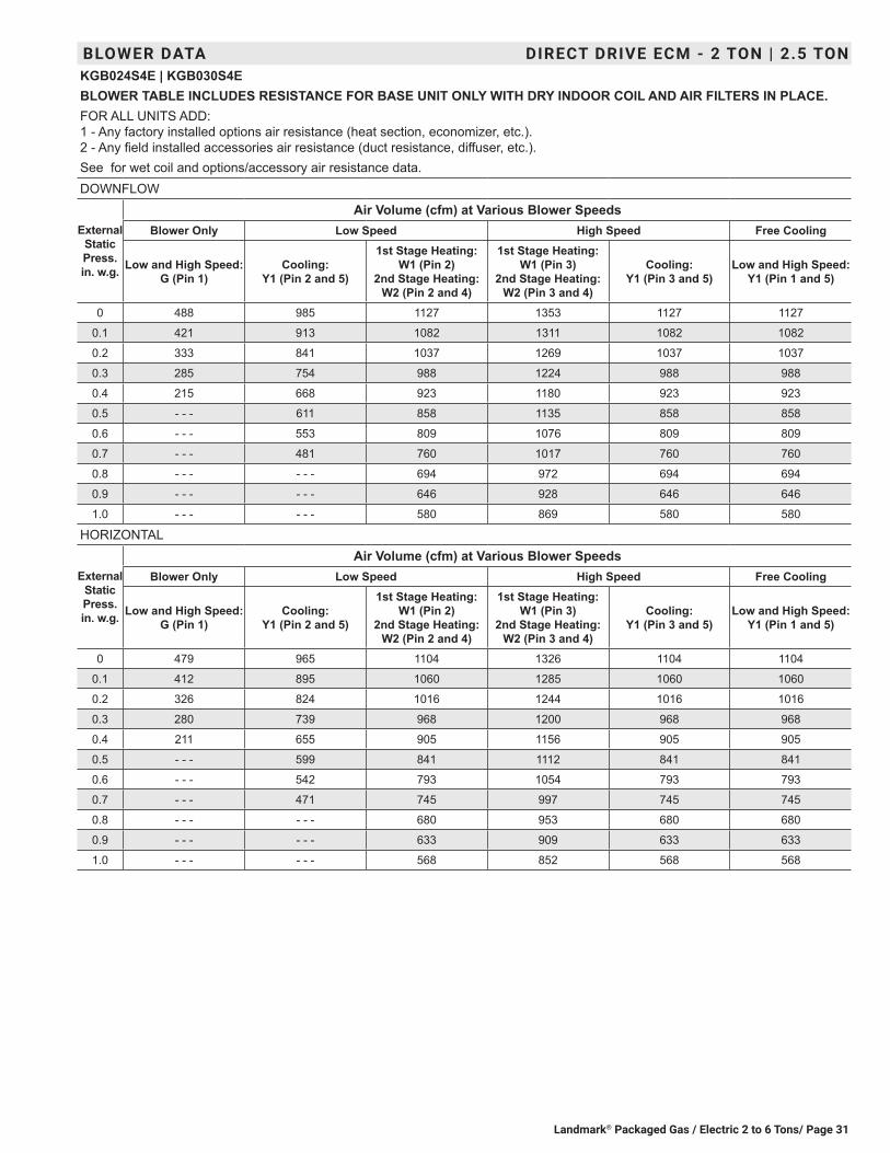
Landmark® Packaged Gas / Electric 2 to 6 Tons/ Page 31
BLOWER DATA DIRECT DRIVE ECM - 2 TON | 2.5 TONKGB024S4E | KGB030S4EBLOWER TABLE INCLUDES RESISTANCE FOR BASE UNIT ONLY WITH DRY INDOOR COIL AND AIR FILTERS IN PLACE.FOR ALL UNITS ADD: 1 - Any factory installed options air resistance (heat section, economizer, etc.). 2 - Any field installed accessories air resistance (duct resistance, diffuser, etc.).See for wet coil and options/accessory air resistance data.DOWNFLOW
External Static Press. in. w.g.
Air Volume (cfm) at Various Blower SpeedsBlower Only Low Speed High Speed Free Cooling
Low and High Speed: G (Pin 1)
Cooling: Y1 (Pin 2 and 5)
1st Stage Heating: W1 (Pin 2)
2nd Stage Heating: W2 (Pin 2 and 4)
1st Stage Heating: W1 (Pin 3)
2nd Stage Heating: W2 (Pin 3 and 4)
Cooling: Y1 (Pin 3 and 5)
Low and High Speed: Y1 (Pin 1 and 5)
0 488 985 1127 1353 1127 1127
0.1 421 913 1082 1311 1082 1082
0.2 333 841 1037 1269 1037 1037
0.3 285 754 988 1224 988 988
0.4 215 668 923 1180 923 923
0.5 - - - 611 858 1135 858 858
0.6 - - - 553 809 1076 809 809
0.7 - - - 481 760 1017 760 760
0.8 - - - - - - 694 972 694 694
0.9 - - - - - - 646 928 646 646
1.0 - - - - - - 580 869 580 580
HORIZONTAL
External Static Press. in. w.g.
Air Volume (cfm) at Various Blower SpeedsBlower Only Low Speed High Speed Free Cooling
Low and High Speed: G (Pin 1)
Cooling: Y1 (Pin 2 and 5)
1st Stage Heating: W1 (Pin 2)
2nd Stage Heating: W2 (Pin 2 and 4)
1st Stage Heating: W1 (Pin 3)
2nd Stage Heating: W2 (Pin 3 and 4)
Cooling: Y1 (Pin 3 and 5)
Low and High Speed: Y1 (Pin 1 and 5)
0 479 965 1104 1326 1104 1104
0.1 412 895 1060 1285 1060 1060
0.2 326 824 1016 1244 1016 1016
0.3 280 739 968 1200 968 968
0.4 211 655 905 1156 905 905
0.5 - - - 599 841 1112 841 841
0.6 - - - 542 793 1054 793 793
0.7 - - - 471 745 997 745 745
0.8 - - - - - - 680 953 680 680
0.9 - - - - - - 633 909 633 633
1.0 - - - - - - 568 852 568 568

Landmark® Packaged Gas / Electric 2 to 6 Tons / Page 32
BLOWER DATA DIRECT DRIVE ECM - 3 TONKGB036S4EBLOWER TABLE INCLUDES RESISTANCE FOR BASE UNIT ONLY WITH DRY INDOOR COIL AND AIR FILTERS IN PLACE.FOR ALL UNITS ADD: 1 - Any factory installed options air resistance (heat section, economizer, etc.). 2 - Any field installed accessories air resistance (duct resistance, diffuser, etc.).See for wet coil and options/accessory air resistance data.DOWNFLOW
External Static Press. in. w.g.
Air Volume (cfm) at Various Blower SpeedsBlower Only Low Speed High Speed Free Cooling
Low and High Speed:
G (Pin 1)
1st Stage Heating: W1 (Pin 2) Cooling:
Y1 (Pin 2 and 5)
2nd Stage Heating:
W2 (Pin 2 and 4)
1st Stage Heating:
W1 (Pin 3)
2nd Stage Heating:
W2 (Pin 3 and 4)
Cooling: Y1 (Pin 3 and 5)
Low and High Speed:
Y1 (Pin 1 and 5)
0 862 1375 1567 1706 1840 1567 1567
0.1 809 1330 1539 1682 1780 1539 1539
0.2 741 1277 1511 1658 1748 1511 1511
0.3 680 1253 1477 1624 1712 1477 1477
0.4 622 1200 1443 1598 1677 1443 1443
0.5 555 1150 1409 1564 1638 1409 1409
0.6 - - - 1095 1364 1530 1608 1364 1364
0.7 - - - 1052 1330 1496 1577 1330 1330
0.8 - - - 1004 1296 1444 1528 1296 1296
0.9 - - - 950 1251 1419 1491 1251 1251
1.0 - - - 900 1206 1394 1455 1206 1206
HORIZONTAL
External Static Press. in. w.g.
Air Volume (cfm) at Various Blower SpeedsBlower Only Low Speed High Speed Free Cooling
Low and High Speed:
G (Pin 1)
1st Stage Heating: W1 (Pin 2) Cooling:
Y1 (Pin 2 and 5)
2nd Stage Heating:
W2 (Pin 2 and 4)
1st Stage Heating:
W1 (Pin 3)
2nd Stage Heating:
W2 (Pin 3 and 4)
Cooling: Y1 (Pin 3 and 5)
Low and High Speed:
Y1 (Pin 1 and 5)
0 479 1379 1536 1672 1810 1536 1536
0.1 412 1305 1508 1648 1749 1508 1508
0.2 326 1264 1481 1625 1718 1481 1481
0.3 280 1216 1447 1592 1677 1447 1447
0.4 211 1173 1414 1566 1649 1414 1414
0.5 - - - 1131 1381 1533 1622 1381 1381
0.6 - - - 1078 1337 1499 1577 1337 1337
0.7 - - - 1038 1303 1466 1544 1303 1303
0.8 - - - 986 1270 1415 1509 1270 1270
0.9 - - - 933 1226 1391 1471 1226 1226
1.0 - - - 885 1182 1366 1438 1182 1182

Landmark® Packaged Gas / Electric 2 to 6 Tons/ Page 33
BLOWER DATA DIRECT DRIVE ECM - 4 TONKGB048S4EBLOWER TABLE INCLUDES RESISTANCE FOR BASE UNIT ONLY WITH DRY INDOOR COIL AND AIR FILTERS IN PLACE.FOR ALL UNITS ADD: 1 - Any factory installed options air resistance (larger gas heat section, economizer, wet coil, etc.) See page 46. 2 - Any field installed accessories air resistance (duct resistance, diffuser, etc.) See page 46.DOWNFLOW
External Static Press. in. w.g.
Air Volume (cfm) at Various Blower SpeedsBlower Only Low Speed High Speed Free Cooling
Low and High Speed: G (Pin 1)
Cooling: Y1 (Pin 2 and 5)
1st Stage Heating: W1 (Pin 2)
2nd Stage Heating: W2 (Pin 2 and 4)
2nd Stage Heating: W2 (Pin 3 and 4)
1st Stage Heating: W1 (Pin 3) Cooling:
Y1 (Pin 3 and 5)
Low and High Speed: Y1 (Pin 1 and 5)
0 963 1561 1869 2156 1869 1958
0.1 897 1530 1842 2132 1842 1920
0.2 831 1499 1815 2108 1815 1882
0.3 752 1466 1788 2084 1788 1844
0.4 673 1432 1750 2057 1750 1814
0.5 620 1398 1723 2031 1723 1784
0.6 567 1353 1695 1991 1695 1754
0.7 501 1319 1658 1952 1658 1724
0.8 - - - 1274 1621 1899 1621 1694
0.9 - - - 1240 1593 1794 1593 1672
1.0 - - - 1184 1556 1689 1556 1650
HORIZONTAL
External Static Press. in. w.g.
Air Volume (cfm) at Various Blower SpeedsBlower Only Low Speed High Speed Free Cooling
Low and High Speed: G (Pin 1)
Cooling: Y1 (Pin 2 and 5)
1st Stage Heating: W1 (Pin 2)
2nd Stage Heating: W2 (Pin 2 and 4)
2nd Stage Heating: W2 (Pin 3 and 4)
1st Stage Heating: W1 (Pin 3) Cooling:
Y1 (Pin 3 and 5)
Low and High Speed: Y1 (Pin 1 and 5)
0 944 1530 1832 2113 1832 1919
0.1 879 1499 1805 2089 1805 1882
0.2 814 1469 1779 2066 1779 1844
0.3 737 1437 1752 2042 1752 1807
0.4 660 1403 1715 2016 1715 1778
0.5 608 1370 1689 1990 1689 1748
0.6 556 1326 1661 1951 1661 1719
0.7 491 1293 1625 1913 1625 1690
0.8 - - - 1249 1589 1861 1589 1660
0.9 - - - 1215 1561 1758 1561 1639
1.0 - - - 1160 1525 1655 1525 1617
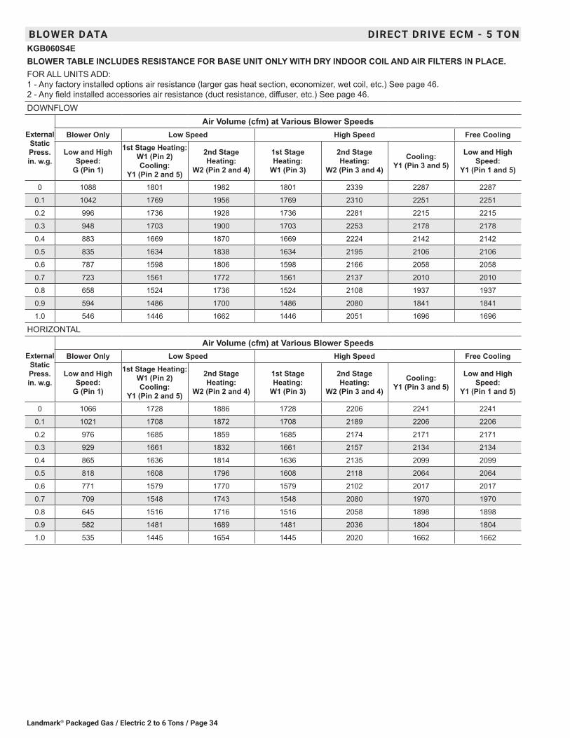
Landmark® Packaged Gas / Electric 2 to 6 Tons / Page 34
BLOWER DATA DIRECT DRIVE ECM - 5 TONKGB060S4EBLOWER TABLE INCLUDES RESISTANCE FOR BASE UNIT ONLY WITH DRY INDOOR COIL AND AIR FILTERS IN PLACE.FOR ALL UNITS ADD: 1 - Any factory installed options air resistance (larger gas heat section, economizer, wet coil, etc.) See page 46. 2 - Any field installed accessories air resistance (duct resistance, diffuser, etc.) See page 46.DOWNFLOW
External Static Press. in. w.g.
Air Volume (cfm) at Various Blower SpeedsBlower Only Low Speed High Speed Free Cooling
Low and High Speed:
G (Pin 1)
1st Stage Heating: W1 (Pin 2) Cooling:
Y1 (Pin 2 and 5)
2nd Stage Heating:
W2 (Pin 2 and 4)
1st Stage Heating:
W1 (Pin 3)
2nd Stage Heating:
W2 (Pin 3 and 4)
Cooling: Y1 (Pin 3 and 5)
Low and High Speed:
Y1 (Pin 1 and 5)
0 1088 1801 1982 1801 2339 2287 2287
0.1 1042 1769 1956 1769 2310 2251 2251
0.2 996 1736 1928 1736 2281 2215 2215
0.3 948 1703 1900 1703 2253 2178 2178
0.4 883 1669 1870 1669 2224 2142 2142
0.5 835 1634 1838 1634 2195 2106 2106
0.6 787 1598 1806 1598 2166 2058 2058
0.7 723 1561 1772 1561 2137 2010 2010
0.8 658 1524 1736 1524 2108 1937 1937
0.9 594 1486 1700 1486 2080 1841 1841
1.0 546 1446 1662 1446 2051 1696 1696
HORIZONTAL
External Static Press. in. w.g.
Air Volume (cfm) at Various Blower SpeedsBlower Only Low Speed High Speed Free Cooling
Low and High Speed:
G (Pin 1)
1st Stage Heating: W1 (Pin 2) Cooling:
Y1 (Pin 2 and 5)
2nd Stage Heating:
W2 (Pin 2 and 4)
1st Stage Heating:
W1 (Pin 3)
2nd Stage Heating:
W2 (Pin 3 and 4)
Cooling: Y1 (Pin 3 and 5)
Low and High Speed:
Y1 (Pin 1 and 5)
0 1066 1728 1886 1728 2206 2241 2241
0.1 1021 1708 1872 1708 2189 2206 2206
0.2 976 1685 1859 1685 2174 2171 2171
0.3 929 1661 1832 1661 2157 2134 2134
0.4 865 1636 1814 1636 2135 2099 2099
0.5 818 1608 1796 1608 2118 2064 2064
0.6 771 1579 1770 1579 2102 2017 2017
0.7 709 1548 1743 1548 2080 1970 1970
0.8 645 1516 1716 1516 2058 1898 1898
0.9 582 1481 1689 1481 2036 1804 1804
1.0 535 1445 1654 1445 2020 1662 1662

Landmark® Packaged Gas / Electric 2 to 6 Tons/ Page 35
BLOWER DATA DIRECT DRIVE PSC - 3 TON | 4 TONKGB036S4D | KGB048S4DBLOWER TABLE INCLUDES RESISTANCE FOR BASE UNIT ONLY WITH DRY INDOOR COIL AND AIR FILTERS IN PLACE.FOR ALL UNITS ADD: 1 - Any factory installed options air resistance (larger gas heat section, economizer, wet coil, etc.) See page 46. 2 - Any field installed accessories air resistance (duct resistance, diffuser, etc.) See page 46.
External Static Pressure (in. w.g.)
Air Volume (cfm) at Various Blower Speeds208 VOLTS 230 VOLTS 460/575 VOLTS
High Medium Low High Medium Low High Medium Low3 and 4 Ton Standard Efficiency (Downflow) KGB036S and KGB048S
0.0 1873 1561 1123 2094 1783 1321 2064 1727 12160.1 1993 1601 1148 2168 1797 1338 2105 1744 12290.2 1913 1601 1137 2098 1803 1308 2050 1694 11980.3 1858 1527 1078 2036 1725 1261 1987 1638 11670.4 1801 1496 1046 1973 1679 1219 1905 1598 11480.5 1763 1467 987 1910 1647 1177 1862 1559 11080.6 1709 1414 897 1830 1560 1080 1781 1509 10570.7 1617 1368 806 1727 1519 986 1698 1449 9820.8 1472 1269 730 1604 1419 918 1614 1389 9200.9 1359 1162 487 1478 1363 706 1488 1346 7921.0 961 922 370 1093 1083 590 1167 1099 703
3 and 4 Ton Standard Efficiency (Horizontal) KGB036S and KGB048S0.0 1799 1530 1073 2012 1747 1263 2015 1756 12510.1 1868 1544 1088 2032 1733 1268 2071 1760 12790.2 1802 1494 1068 1976 1682 1228 2014 1700 12260.3 1735 1432 1014 1900 1618 1185 1937 1634 11870.4 1666 1397 980 1825 1568 1142 1878 1597 11740.5 1615 1350 904 1750 1516 1078 1801 1558 11240.6 1564 1305 842 1675 1440 1014 1743 1479 10600.7 1462 1228 758 1562 1364 928 1664 1415 9820.8 1330 1151 670 1449 1287 842 1512 1335 8650.9 1194 1011 464 1298 1185 671 1393 1297 7331.0 878 878 355 998 1032 565 1060 1063 618
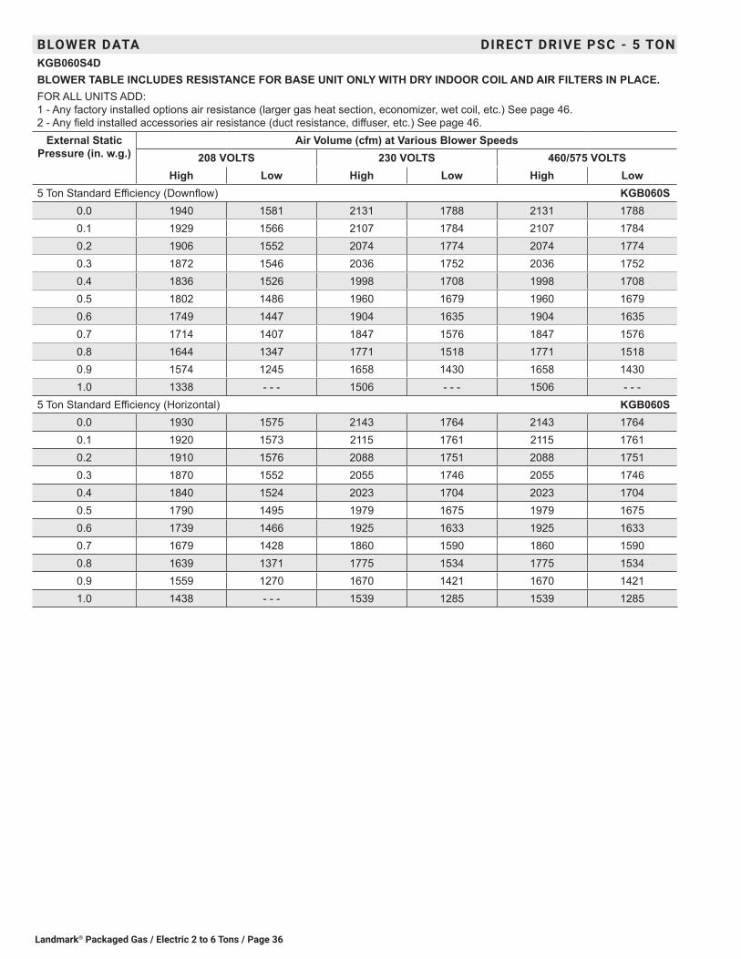
Landmark® Packaged Gas / Electric 2 to 6 Tons / Page 36
BLOWER DATA DIRECT DRIVE PSC - 5 TONKGB060S4DBLOWER TABLE INCLUDES RESISTANCE FOR BASE UNIT ONLY WITH DRY INDOOR COIL AND AIR FILTERS IN PLACE.FOR ALL UNITS ADD: 1 - Any factory installed options air resistance (larger gas heat section, economizer, wet coil, etc.) See page 46. 2 - Any field installed accessories air resistance (duct resistance, diffuser, etc.) See page 46.
External Static Pressure (in. w.g.)
Air Volume (cfm) at Various Blower Speeds208 VOLTS 230 VOLTS 460/575 VOLTS
High Low High Low High Low5 Ton Standard Efficiency (Downflow) KGB060S
0.0 1940 1581 2131 1788 2131 17880.1 1929 1566 2107 1784 2107 17840.2 1906 1552 2074 1774 2074 17740.3 1872 1546 2036 1752 2036 17520.4 1836 1526 1998 1708 1998 17080.5 1802 1486 1960 1679 1960 16790.6 1749 1447 1904 1635 1904 16350.7 1714 1407 1847 1576 1847 15760.8 1644 1347 1771 1518 1771 15180.9 1574 1245 1658 1430 1658 14301.0 1338 - - - 1506 - - - 1506 - - -
5 Ton Standard Efficiency (Horizontal) KGB060S0.0 1930 1575 2143 1764 2143 17640.1 1920 1573 2115 1761 2115 17610.2 1910 1576 2088 1751 2088 17510.3 1870 1552 2055 1746 2055 17460.4 1840 1524 2023 1704 2023 17040.5 1790 1495 1979 1675 1979 16750.6 1739 1466 1925 1633 1925 16330.7 1679 1428 1860 1590 1860 15900.8 1639 1371 1775 1534 1775 15340.9 1559 1270 1670 1421 1670 14211.0 1438 - - - 1539 1285 1539 1285

Landmark® Packaged Gas / Electric 2 to 6 Tons/ Page 37
BLOWER BELT DRIVE (SINGLE SPEED) - 3 TONKGB036S4BBLOWER TABLE INCLUDES RESISTANCE FOR BASE UNIT ONLY WITH DRY INDOOR COIL AND AIR FILTERS IN PLACE.FOR ALL UNITS ADD: 1 - Any factory installed options air resistance (heat section, economizer, wet coil, etc.). 2 - Any field installed accessories air resistance (duct resistance, diffuser, etc.). See page 46 for blower motors and drives and wet coil and options/accessory air resistance data.
DOWNFLOW
Air Volume
cfm
External Static - in. w.g.0.10 0.20 0.30 0.40 0.50 0.60 0.70 0.80
RPM BHP RPM BHP RPM BHP RPM BHP RPM BHP RPM BHP RPM BHP RPM BHP900 493 0.11 564 0.15 637 0.19 711 0.22 783 0.24 851 0.26 910 0.29 961 0.32
1000 517 0.14 588 0.18 660 0.22 733 0.24 804 0.26 868 0.29 924 0.32 974 0.351100 544 0.17 614 0.21 685 0.25 757 0.27 826 0.29 887 0.32 940 0.36 987 0.381200 574 0.2 643 0.24 712 0.28 782 0.31 849 0.33 906 0.36 956 0.39 1001 0.421300 613 0.23 679 0.28 745 0.31 811 0.34 873 0.36 926 0.40 973 0.43 1016 0.461400 662 0.26 722 0.30 781 0.34 841 0.37 897 0.41 944 0.44 989 0.48 1032 0.511500 710 0.29 763 0.33 816 0.38 869 0.41 919 0.45 963 0.49 1006 0.53 1049 0.56
Air Volume
cfm
External Static - in. w.g.0.90 1.00 1.10 1.20 1.30 1.40 1.50 1.60
RPM BHP RPM BHP RPM BHP RPM BHP RPM BHP RPM BHP RPM BHP RPM BHP900 1008 0.34 1056 0.36 1104 0.39 1149 0.41 1190 0.44 1229 0.46 1267 0.49 1305 0.52
1000 1020 0.37 1067 0.40 1115 0.42 1159 0.45 1200 0.48 1239 0.51 1277 0.54 1314 0.571100 1032 0.41 1078 0.43 1124 0.46 1168 0.49 1210 0.52 1249 0.55 1286 0.58 1323 0.621200 1045 0.45 1090 0.47 1135 0.50 1178 0.53 1220 0.57 1259 0.60 1296 0.64 1332 0.671300 1060 0.49 1104 0.51 1148 0.55 1190 0.58 1230 0.62 1269 0.65 1306 0.69 1342 0.721400 1075 0.53 1119 0.56 1162 0.60 1203 0.63 1242 0.67 1280 0.71 1317 0.75 1352 0.781500 1093 0.58 1136 0.61 1177 0.65 1217 0.69 1255 0.73 1292 0.77 1328 0.80 1364 0.84
HORIZONTAL
Air Volume
cfm
External Static - in. w.g.0.10 0.20 0.30 0.40 0.50 0.60 0.70 0.80
RPM BHP RPM BHP RPM BHP RPM BHP RPM BHP RPM BHP RPM BHP RPM BHP900 465 0.09 531 0.14 600 0.17 670 0.20 740 0.22 808 0.24 869 0.27 925 0.30
1000 483 0.12 549 0.16 617 0.20 687 0.22 756 0.24 822 0.26 881 0.29 935 0.331100 504 0.14 570 0.19 637 0.22 706 0.25 773 0.27 837 0.29 894 0.32 946 0.361200 527 0.17 592 0.22 658 0.25 726 0.28 792 0.30 854 0.32 908 0.36 957 0.391300 552 0.20 617 0.25 682 0.29 748 0.31 812 0.33 871 0.36 923 0.40 970 0.431400 580 0.24 644 0.28 708 0.32 773 0.35 834 0.37 890 0.40 938 0.44 984 0.481500 611 0.28 674 0.32 736 0.35 799 0.38 857 0.41 908 0.44 954 0.49 998 0.52
Air Volume
cfm
External Static - in. w.g.0.90 1.00 1.10 1.20 1.30 1.40 1.50 1.60
RPM BHP RPM BHP RPM BHP RPM BHP RPM BHP RPM BHP RPM BHP RPM BHP900 977 0.33 1028 0.36 1079 0.39 1127 0.42 1169 0.45 1208 0.48 1246 0.51 1282 0.54
1000 985 0.36 1036 0.39 1087 0.42 1135 0.45 1177 0.48 1216 0.52 1253 0.55 1290 0.581100 995 0.39 1044 0.42 1093 0.45 1140 0.49 1183 0.52 1223 0.56 1261 0.59 1297 0.621200 1005 0.43 1053 0.46 1100 0.49 1146 0.53 1190 0.56 1230 0.60 1268 0.63 1304 0.671300 1016 0.47 1063 0.50 1109 0.53 1154 0.57 1197 0.61 1237 0.64 1275 0.68 1311 0.721400 1029 0.51 1074 0.54 1120 0.58 1164 0.61 1205 0.65 1245 0.69 1282 0.73 1318 0.771500 1042 0.56 1087 0.59 1132 0.62 1174 0.66 1215 0.71 1253 0.75 1290 0.78 1326 0.82
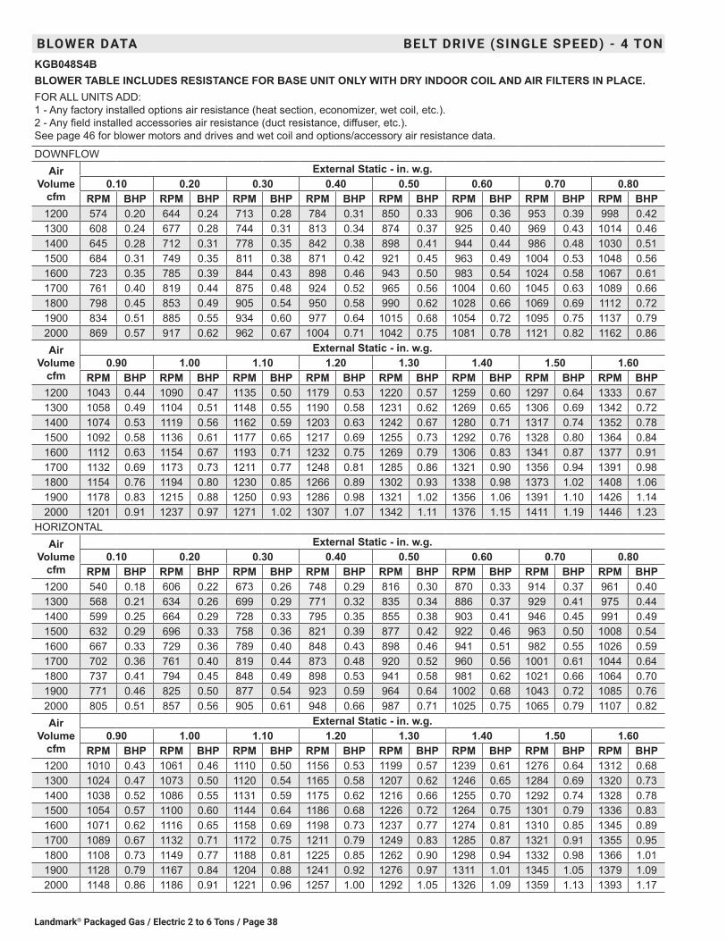
Landmark® Packaged Gas / Electric 2 to 6 Tons / Page 38
BLOWER DATA BELT DRIVE (SINGLE SPEED) - 4 TONKGB048S4BBLOWER TABLE INCLUDES RESISTANCE FOR BASE UNIT ONLY WITH DRY INDOOR COIL AND AIR FILTERS IN PLACE.FOR ALL UNITS ADD: 1 - Any factory installed options air resistance (heat section, economizer, wet coil, etc.). 2 - Any field installed accessories air resistance (duct resistance, diffuser, etc.). See page 46 for blower motors and drives and wet coil and options/accessory air resistance data.
DOWNFLOWAir
Volume cfm
External Static - in. w.g.0.10 0.20 0.30 0.40 0.50 0.60 0.70 0.80
RPM BHP RPM BHP RPM BHP RPM BHP RPM BHP RPM BHP RPM BHP RPM BHP1200 574 0.20 644 0.24 713 0.28 784 0.31 850 0.33 906 0.36 953 0.39 998 0.421300 608 0.24 677 0.28 744 0.31 813 0.34 874 0.37 925 0.40 969 0.43 1014 0.461400 645 0.28 712 0.31 778 0.35 842 0.38 898 0.41 944 0.44 986 0.48 1030 0.511500 684 0.31 749 0.35 811 0.38 871 0.42 921 0.45 963 0.49 1004 0.53 1048 0.561600 723 0.35 785 0.39 844 0.43 898 0.46 943 0.50 983 0.54 1024 0.58 1067 0.611700 761 0.40 819 0.44 875 0.48 924 0.52 965 0.56 1004 0.60 1045 0.63 1089 0.661800 798 0.45 853 0.49 905 0.54 950 0.58 990 0.62 1028 0.66 1069 0.69 1112 0.721900 834 0.51 885 0.55 934 0.60 977 0.64 1015 0.68 1054 0.72 1095 0.75 1137 0.792000 869 0.57 917 0.62 962 0.67 1004 0.71 1042 0.75 1081 0.78 1121 0.82 1162 0.86Air
Volume cfm
External Static - in. w.g.0.90 1.00 1.10 1.20 1.30 1.40 1.50 1.60
RPM BHP RPM BHP RPM BHP RPM BHP RPM BHP RPM BHP RPM BHP RPM BHP1200 1043 0.44 1090 0.47 1135 0.50 1179 0.53 1220 0.57 1259 0.60 1297 0.64 1333 0.671300 1058 0.49 1104 0.51 1148 0.55 1190 0.58 1231 0.62 1269 0.65 1306 0.69 1342 0.721400 1074 0.53 1119 0.56 1162 0.59 1203 0.63 1242 0.67 1280 0.71 1317 0.74 1352 0.781500 1092 0.58 1136 0.61 1177 0.65 1217 0.69 1255 0.73 1292 0.76 1328 0.80 1364 0.841600 1112 0.63 1154 0.67 1193 0.71 1232 0.75 1269 0.79 1306 0.83 1341 0.87 1377 0.911700 1132 0.69 1173 0.73 1211 0.77 1248 0.81 1285 0.86 1321 0.90 1356 0.94 1391 0.981800 1154 0.76 1194 0.80 1230 0.85 1266 0.89 1302 0.93 1338 0.98 1373 1.02 1408 1.061900 1178 0.83 1215 0.88 1250 0.93 1286 0.98 1321 1.02 1356 1.06 1391 1.10 1426 1.142000 1201 0.91 1237 0.97 1271 1.02 1307 1.07 1342 1.11 1376 1.15 1411 1.19 1446 1.23
HORIZONTALAir
Volume cfm
External Static - in. w.g.0.10 0.20 0.30 0.40 0.50 0.60 0.70 0.80
RPM BHP RPM BHP RPM BHP RPM BHP RPM BHP RPM BHP RPM BHP RPM BHP1200 540 0.18 606 0.22 673 0.26 748 0.29 816 0.30 870 0.33 914 0.37 961 0.401300 568 0.21 634 0.26 699 0.29 771 0.32 835 0.34 886 0.37 929 0.41 975 0.441400 599 0.25 664 0.29 728 0.33 795 0.35 855 0.38 903 0.41 946 0.45 991 0.491500 632 0.29 696 0.33 758 0.36 821 0.39 877 0.42 922 0.46 963 0.50 1008 0.541600 667 0.33 729 0.36 789 0.40 848 0.43 898 0.46 941 0.51 982 0.55 1026 0.591700 702 0.36 761 0.40 819 0.44 873 0.48 920 0.52 960 0.56 1001 0.61 1044 0.641800 737 0.41 794 0.45 848 0.49 898 0.53 941 0.58 981 0.62 1021 0.66 1064 0.701900 771 0.46 825 0.50 877 0.54 923 0.59 964 0.64 1002 0.68 1043 0.72 1085 0.762000 805 0.51 857 0.56 905 0.61 948 0.66 987 0.71 1025 0.75 1065 0.79 1107 0.82Air
Volume cfm
External Static - in. w.g.0.90 1.00 1.10 1.20 1.30 1.40 1.50 1.60
RPM BHP RPM BHP RPM BHP RPM BHP RPM BHP RPM BHP RPM BHP RPM BHP1200 1010 0.43 1061 0.46 1110 0.50 1156 0.53 1199 0.57 1239 0.61 1276 0.64 1312 0.681300 1024 0.47 1073 0.50 1120 0.54 1165 0.58 1207 0.62 1246 0.65 1284 0.69 1320 0.731400 1038 0.52 1086 0.55 1131 0.59 1175 0.62 1216 0.66 1255 0.70 1292 0.74 1328 0.781500 1054 0.57 1100 0.60 1144 0.64 1186 0.68 1226 0.72 1264 0.75 1301 0.79 1336 0.831600 1071 0.62 1116 0.65 1158 0.69 1198 0.73 1237 0.77 1274 0.81 1310 0.85 1345 0.891700 1089 0.67 1132 0.71 1172 0.75 1211 0.79 1249 0.83 1285 0.87 1321 0.91 1355 0.951800 1108 0.73 1149 0.77 1188 0.81 1225 0.85 1262 0.90 1298 0.94 1332 0.98 1366 1.011900 1128 0.79 1167 0.84 1204 0.88 1241 0.92 1276 0.97 1311 1.01 1345 1.05 1379 1.092000 1148 0.86 1186 0.91 1221 0.96 1257 1.00 1292 1.05 1326 1.09 1359 1.13 1393 1.17

Landmark® Packaged Gas / Electric 2 to 6 Tons/ Page 39
BLOWER DATA BELT DRIVE (SINGLE SPEED) - 5 TONKGB060S4BBLOWER TABLE INCLUDES RESISTANCE FOR BASE UNIT ONLY WITH DRY INDOOR COIL AND AIR FILTERS IN PLACE.FOR ALL UNITS ADD: 1 - Any factory installed options air resistance (heat section, economizer, wet coil, etc.). 2 - Any field installed accessories air resistance (duct resistance, diffuser, etc.). See page 46 for blower motors and drives and wet coil and options/accessory air resistance data.
DOWNFLOWAir
Volume cfm
External Static - in. w.g.0.10 0.20 0.30 0.40 0.50 0.60 0.70 0.80
RPM BHP RPM BHP RPM BHP RPM BHP RPM BHP RPM BHP RPM BHP RPM BHP1600 720 0.28 769 0.33 819 0.37 871 0.41 926 0.44 975 0.47 1016 0.51 1054 0.551700 779 0.30 822 0.35 864 0.39 908 0.44 953 0.48 995 0.52 1034 0.57 1072 0.611800 828 0.34 864 0.39 901 0.43 938 0.48 977 0.53 1015 0.58 1053 0.63 1091 0.671900 858 0.41 892 0.45 927 0.50 962 0.55 999 0.60 1036 0.65 1074 0.69 1112 0.732000 879 0.47 913 0.52 948 0.56 984 0.61 1020 0.67 1058 0.72 1096 0.76 1134 0.802100 900 0.53 935 0.58 970 0.63 1007 0.69 1044 0.74 1081 0.79 1119 0.84 1157 0.882200 922 0.60 958 0.65 994 0.71 1031 0.76 1068 0.82 1106 0.87 1143 0.91 1180 0.952300 947 0.67 983 0.73 1020 0.79 1057 0.85 1094 0.90 1131 0.95 1168 1.00 1205 1.032400 974 0.76 1010 0.82 1047 0.88 1084 0.94 1120 0.99 1157 1.04 1193 1.08 1230 1.12Air
Volume cfm
External Static - in. w.g.0.90 1.00 1.10 1.20 1.30 1.40 1.50 1.60
RPM BHP RPM BHP RPM BHP RPM BHP RPM BHP RPM BHP RPM BHP RPM BHP1600 1093 0.60 1133 0.63 1173 0.67 1214 0.70 1253 0.73 1288 0.77 1318 0.81 1351 0.851700 1111 0.65 1150 0.69 1190 0.72 1230 0.76 1268 0.79 1301 0.83 1331 0.87 1363 0.921800 1130 0.71 1169 0.75 1208 0.78 1247 0.82 1285 0.86 1317 0.90 1345 0.94 1377 0.981900 1150 0.77 1188 0.81 1227 0.85 1267 0.88 1303 0.92 1333 0.97 1361 1.02 1392 1.062000 1172 0.84 1210 0.88 1248 0.92 1286 0.96 1321 1.00 1350 1.05 1377 1.10 1409 1.142100 1195 0.91 1233 0.95 1269 1.00 1306 1.04 1339 1.09 1367 1.14 1395 1.19 1426 1.232200 1218 0.99 1255 1.03 1290 1.09 1324 1.14 1356 1.19 1385 1.24 1413 1.28 1444 1.322300 1242 1.07 1277 1.13 1310 1.20 1343 1.26 1374 1.30 1403 1.34 1432 1.38 1464 1.422400 1267 1.16 1300 1.23 1332 1.31 1364 1.37 1394 1.41 1423 1.45 1453 1.48 1484 1.53
HORIZONTALAir
Volume cfm
External Static - in. w.g.0.10 0.20 0.30 0.40 0.50 0.60 0.70 0.80
RPM BHP RPM BHP RPM BHP RPM BHP RPM BHP RPM BHP RPM BHP RPM BHP1600 654 0.28 712 0.32 769 0.36 825 0.39 879 0.43 933 0.47 982 0.50 1024 0.541700 703 0.31 756 0.35 807 0.39 858 0.43 906 0.47 955 0.51 999 0.55 1039 0.591800 752 0.34 798 0.38 844 0.43 889 0.48 933 0.52 977 0.57 1017 0.61 1056 0.651900 796 0.38 837 0.43 878 0.48 918 0.53 958 0.58 997 0.62 1036 0.67 1074 0.712000 833 0.43 870 0.48 907 0.54 943 0.59 980 0.64 1018 0.69 1055 0.73 1093 0.772100 864 0.50 897 0.55 931 0.60 966 0.65 1002 0.71 1038 0.76 1075 0.80 1113 0.832200 887 0.57 920 0.62 953 0.67 988 0.73 1024 0.78 1060 0.83 1097 0.87 1135 0.902300 909 0.64 942 0.70 976 0.75 1011 0.81 1046 0.86 1083 0.91 1120 0.95 1157 0.982400 931 0.72 965 0.78 999 0.83 1035 0.89 1071 0.94 1108 0.99 1144 1.03 1181 1.07Air
Volume cfm
External Static - in. w.g.0.90 1.00 1.10 1.20 1.30 1.40 1.50 1.60
RPM BHP RPM BHP RPM BHP RPM BHP RPM BHP RPM BHP RPM BHP RPM BHP1600 1063 0.58 1101 0.61 1141 0.64 1181 0.67 1222 0.70 1261 0.73 1298 0.77 1333 0.811700 1078 0.63 1117 0.66 1156 0.69 1196 0.72 1235 0.75 1273 0.79 1309 0.83 1344 0.871800 1094 0.68 1133 0.72 1172 0.75 1211 0.78 1250 0.81 1287 0.85 1322 0.90 1355 0.941900 1112 0.74 1151 0.77 1190 0.81 1228 0.84 1265 0.88 1301 0.92 1335 0.97 1367 1.012000 1131 0.80 1170 0.83 1208 0.87 1245 0.91 1281 0.96 1316 1.00 1349 1.04 1380 1.092100 1151 0.87 1189 0.90 1227 0.94 1263 0.99 1298 1.04 1331 1.08 1363 1.13 1394 1.172200 1173 0.94 1210 0.98 1246 1.02 1281 1.07 1315 1.12 1347 1.17 1379 1.22 1409 1.262300 1195 1.02 1231 1.06 1266 1.11 1300 1.16 1333 1.22 1364 1.27 1395 1.32 1424 1.362400 1217 1.10 1252 1.15 1286 1.20 1319 1.26 1351 1.32 1382 1.38 1411 1.43 1440 1.48

Landmark® Packaged Gas / Electric 2 to 6 Tons / Page 40
BLOWER DATA BELT DRIVE (SINGLE AND TWO-SPEED - 6 TON (DOWNFLOW)KGB074S4B | KGB074S4TBLOWER TABLE INCLUDES RESISTANCE FOR BASE UNIT ONLY WITH DRY INDOOR COIL AND AIR FILTERS IN PLACE.FOR ALL UNITS ADD: 1 - Any factory installed options air resistance (heat section, economizer, wet coil, etc.). 2 - Any field installed accessories air resistance (duct resistance, diffuser, etc.). See page 46 for blower motors and drives and wet coil and options/accessory air resistance data.
Air Volume
cfm
External Static - in. w.g.0.10 0.20 0.30 0.40 0.50 0.60 0.70 0.80
RPM BHP RPM BHP RPM BHP RPM BHP RPM BHP RPM BHP RPM BHP RPM BHP1900 857 0.41 892 0.45 927 0.50 962 0.55 999 0.60 1036 0.65 1074 0.69 1112 0.732000 879 0.47 913 0.52 948 0.56 984 0.61 1020 0.67 1058 0.72 1096 0.76 1134 0.802100 900 0.53 935 0.58 970 0.63 1007 0.69 1044 0.74 1081 0.79 1119 0.84 1157 0.882200 922 0.60 958 0.65 994 0.71 1031 0.76 1068 0.82 1106 0.87 1143 0.91 1180 0.952300 947 0.67 983 0.73 1020 0.79 1057 0.85 1094 0.90 1131 0.95 1168 1.00 1205 1.032400 974 0.76 1010 0.82 1047 0.88 1084 0.94 1120 0.99 1157 1.04 1193 1.08 1230 1.122500 1002 0.85 1039 0.91 1075 0.97 1112 1.03 1148 1.08 1184 1.13 1220 1.17 1257 1.212600 1032 0.95 1068 1.01 1105 1.07 1141 1.13 1177 1.17 1213 1.22 1248 1.26 1284 1.312700 1062 1.05 1099 1.11 1136 1.17 1172 1.22 1207 1.27 1242 1.32 1277 1.37 1312 1.432800 1094 1.16 1131 1.22 1167 1.27 1202 1.32 1237 1.38 1271 1.43 1305 1.49 1339 1.562900 1127 1.26 1163 1.32 1198 1.38 1233 1.44 1267 1.50 1300 1.56 1334 1.64 1367 1.71
Air Volume
cfm
External Static - in. w.g.0.90 1.00 1.10 1.20 1.30 1.40 1.50 1.60
RPM BHP RPM BHP RPM BHP RPM BHP RPM BHP RPM BHP RPM BHP RPM BHP1900 1150 0.77 1188 0.81 1227 0.85 1267 0.88 1303 0.92 1333 0.97 1360 1.02 1392 1.062000 1172 0.84 1210 0.88 1248 0.92 1286 0.96 1321 1.00 1350 1.05 1377 1.10 1409 1.142100 1195 0.91 1233 0.95 1269 1.00 1306 1.04 1339 1.09 1367 1.14 1395 1.19 1426 1.232200 1218 0.99 1255 1.03 1290 1.09 1324 1.14 1356 1.19 1385 1.24 1413 1.28 1444 1.322300 1242 1.07 1277 1.13 1310 1.20 1343 1.26 1374 1.30 1403 1.34 1432 1.38 1464 1.422400 1267 1.16 1300 1.23 1332 1.31 1364 1.37 1394 1.41 1423 1.45 1453 1.48 1484 1.532500 1292 1.26 1324 1.34 1355 1.42 1387 1.48 1417 1.52 1445 1.56 1475 1.59 1506 1.642600 1318 1.38 1350 1.46 1380 1.55 1411 1.60 1440 1.64 1469 1.68 1498 1.71 1529 1.762700 1345 1.51 1376 1.60 1406 1.68 1436 1.73 1465 1.77 1493 1.80 1523 1.84 1553 1.882800 1372 1.65 1403 1.74 1433 1.82 1462 1.86 1490 1.90 1519 1.93 1548 1.97 1578 2.012900 1399 1.80 1430 1.89 1460 1.96 1489 2.00 1516 2.03 1544 2.06 1573 2.10 1603 2.14

Landmark® Packaged Gas / Electric 2 to 6 Tons/ Page 41
BLOWER DATA BELT DRIVE (SINGLE AND TWO-SPEED) - 6 TON (HORIZONTAL)KGB074S4B | KGB074S4TBLOWER TABLE INCLUDES RESISTANCE FOR BASE UNIT ONLY WITH DRY INDOOR COIL AND AIR FILTERS IN PLACE.FOR ALL UNITS ADD: 1 - Any factory installed options air resistance (heat section, economizer, wet coil, etc.). 2 - Any field installed accessories air resistance (duct resistance, diffuser, etc.). See page 46 for blower motors and drives and wet coil and options/accessory air resistance data.
Air Volume
cfm
External Static - in. w.g.0.10 0.20 0.30 0.40 0.50 0.60 0.70 0.80
RPM BHP RPM BHP RPM BHP RPM BHP RPM BHP RPM BHP RPM BHP RPM BHP1900 796 0.38 837 0.43 878 0.48 918 0.53 958 0.58 997 0.62 1036 0.67 1074 0.712000 833 0.43 870 0.48 907 0.54 943 0.59 980 0.64 1018 0.69 1055 0.73 1093 0.772100 864 0.50 897 0.55 931 0.60 966 0.65 1002 0.71 1038 0.76 1075 0.80 1113 0.832200 887 0.57 920 0.62 953 0.67 988 0.73 1024 0.78 1060 0.83 1097 0.87 1135 0.902300 909 0.64 942 0.70 976 0.75 1011 0.81 1046 0.86 1083 0.91 1120 0.95 1157 0.982400 931 0.72 965 0.78 999 0.83 1035 0.89 1071 0.94 1108 0.99 1144 1.03 1181 1.072500 955 0.80 989 0.86 1024 0.92 1061 0.98 1097 1.03 1133 1.08 1170 1.11 1205 1.152600 981 0.90 1016 0.96 1052 1.01 1088 1.07 1124 1.12 1160 1.16 1195 1.20 1230 1.252700 1009 0.99 1044 1.05 1080 1.11 1116 1.16 1152 1.21 1187 1.26 1221 1.30 1254 1.352800 1038 1.10 1073 1.16 1109 1.21 1145 1.26 1180 1.31 1214 1.36 1247 1.40 1279 1.462900 1068 1.20 1104 1.26 1139 1.31 1174 1.36 1208 1.41 1240 1.47 1273 1.52 1304 1.58
Air Volume
cfm
External Static - in. w.g.0.90 1.00 1.10 1.20 1.30 1.40 1.50 1.60
RPM BHP RPM BHP RPM BHP RPM BHP RPM BHP RPM BHP RPM BHP RPM BHP1900 1112 0.74 1151 0.77 1190 0.81 1228 0.84 1265 0.88 1301 0.92 1335 0.97 1367 1.012000 1131 0.80 1170 0.83 1208 0.87 1245 0.91 1281 0.96 1316 1.00 1349 1.04 1380 1.092100 1151 0.87 1189 0.90 1227 0.94 1263 0.99 1298 1.04 1331 1.08 1363 1.13 1394 1.172200 1173 0.94 1210 0.98 1246 1.02 1281 1.07 1315 1.12 1347 1.17 1379 1.22 1409 1.262300 1195 1.02 1231 1.06 1266 1.11 1300 1.16 1333 1.22 1364 1.27 1395 1.32 1424 1.362400 1217 1.10 1252 1.15 1286 1.20 1319 1.26 1351 1.32 1382 1.38 1411 1.43 1440 1.482500 1240 1.20 1274 1.25 1307 1.31 1339 1.37 1370 1.43 1400 1.49 1428 1.55 1457 1.592600 1264 1.30 1297 1.35 1329 1.42 1360 1.49 1389 1.55 1418 1.61 1446 1.67 1475 1.722700 1287 1.40 1319 1.47 1350 1.54 1380 1.61 1409 1.68 1437 1.74 1465 1.79 1493 1.842800 1311 1.52 1342 1.59 1373 1.66 1402 1.74 1430 1.8 1457 1.87 1485 1.92 1513 1.972900 1335 1.65 1366 1.72 1395 1.79 1424 1.87 1451 1.94 1478 2.00 1505 2.05 1533 2.09
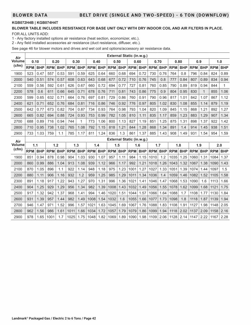
Landmark® Packaged Gas / Electric 2 to 6 Tons / Page 42
BLOWER DATA BELT DRIVE (SINGLE AND TWO-SPEED) - 6 TON (DOWNFLOW)KGB072H4B | KGB074H4TBLOWER TABLE INCLUDES RESISTANCE FOR BASE UNIT ONLY WITH DRY INDOOR COIL AND AIR FILTERS IN PLACE.FOR ALL UNITS ADD: 1 - Any factory installed options air resistance (heat section, economizer, etc.). 2 - Any field installed accessories air resistance (duct resistance, diffuser, etc.).See page 46 for blower motors and drives and wet coil and options/accessory air resistance data.
Air Volume (cfm)
External Static (in.w.g.)0.10 0.20 0.30 0.40 0.50 0.60 0.70 0.80 0.9 1.0
RPM BHP RPM BHP RPM BHP RPM BHP RPM BHP RPM BHP RPM BHP RPM BHP RPM BHP RPM BHP1900 523 0.47 557 0.53 591 0.59 625 0.64 660 0.68 694 0.72 730 0.76 764 0.8 796 0.84 824 0.892000 540 0.51 574 0.57 608 0.63 643 0.68 677 0.72 710 0.76 745 0.8 777 0.84 807 0.89 834 0.942100 559 0.56 592 0.61 626 0.67 660 0.72 694 0.77 727 0.81 760 0.85 790 0.89 819 0.94 844 12200 578 0.6 611 0.66 645 0.71 678 0.76 711 0.81 743 0.86 775 0.9 804 0.95 830 1 855 1.062300 599 0.65 632 0.71 664 0.76 697 0.81 729 0.86 760 0.91 790 0.96 817 1.01 842 1.07 867 1.122400 621 0.71 652 0.76 684 0.81 716 0.86 746 0.92 776 0.97 805 1.02 830 1.08 855 1.14 879 1.192500 642 0.77 673 0.82 704 0.87 734 0.93 764 0.98 793 1.04 820 1.09 845 1.15 868 1.21 892 1.272600 665 0.82 694 0.88 724 0.93 753 0.99 782 1.05 810 1.11 835 1.17 859 1.23 883 1.29 907 1.342700 688 0.89 716 0.94 744 1 773 1.06 800 1.13 827 1.19 851 1.25 875 1.31 898 1.37 922 1.422800 710 0.95 738 1.02 765 1.08 792 1.15 818 1.21 844 1.28 868 1.34 891 1.4 914 1.45 938 1.512900 733 1.03 759 1.1 785 1.17 811 1.24 836 1.3 861 1.37 885 1.43 908 1.49 931 1.54 954 1.59
Air Volume (cfm)
External Static (in.w.g.)1.1 1.2 1.3 1.4 1.5 1.6 1.7 1.8 1.9 2.0
RPM BHP RPM BHP RPM BHP RPM BHP RPM BHP RPM BHP RPM BHP RPM BHP RPM BHP RPM BHP1900 851 0.94 878 0.98 904 1.03 930 1.07 957 1.11 984 1.15 1010 1.2 1035 1.25 1060 1.31 1084 1.372000 860 0.99 886 1.04 913 1.08 939 1.12 966 1.17 992 1.21 1018 1.26 1043 1.32 1067 1.38 1090 1.432100 870 1.05 896 1.1 922 1.14 948 1.18 975 1.23 1001 1.27 1027 1.33 1051 1.39 1074 1.44 1097 1.52200 880 1.11 906 1.16 932 1.2 959 1.25 985 1.29 1011 1.34 1036 1.4 1059 1.46 1082 1.52 1105 1.582300 891 1.18 917 1.22 943 1.27 970 1.31 996 1.36 1021 1.41 1046 1.47 1068 1.53 1090 1.6 1113 1.662400 904 1.25 929 1.29 956 1.34 982 1.39 1008 1.43 1032 1.49 1056 1.55 1078 1.62 1099 1.68 1121 1.752500 917 1.32 942 1.37 968 1.41 994 1.46 1020 1.51 1044 1.57 1066 1.64 1088 1.7 1108 1.77 1130 1.842600 931 1.39 957 1.44 982 1.49 1008 1.54 1032 1.6 1055 1.66 1077 1.73 1098 1.8 1118 1.87 1139 1.942700 946 1.47 971 1.52 996 1.57 1021 1.63 1045 1.69 1067 1.76 1088 1.83 1108 1.91 1127 1.98 1148 2.052800 962 1.56 986 1.61 1011 1.66 1034 1.72 1057 1.79 1079 1.86 1099 1.94 1118 2.02 1137 2.09 1158 2.162900 978 1.65 1001 1.7 1025 1.75 1048 1.82 1069 1.89 1090 1.98 1109 2.06 1128 2.14 1147 2.22 1167 2.28

Landmark® Packaged Gas / Electric 2 to 6 Tons/ Page 43
BLOWER DATA BELT DRIVE (SINGLE AND TWO-SPEED) - 6 TON (HORIZONTAL)KGB072H4B | KGB074H4TBLOWER TABLE INCLUDES RESISTANCE FOR BASE UNIT ONLY WITH DRY INDOOR COIL AND AIR FILTERS IN PLACE.FOR ALL UNITS ADD: 1 - Any factory installed options air resistance (heat section, economizer, etc.). 2 - Any field installed accessories air resistance (duct resistance, diffuser, etc.).See page 46 for blower motors and drives and wet coil and options/accessory air resistance data.
Air Volume (cfm)
External Static (in.w.g.)0.10 0.20 0.30 0.40 0.50 0.60 0.70 0.80 0.9 1.0
RPM BHP RPM BHP RPM BHP RPM BHP RPM BHP RPM BHP RPM BHP RPM BHP RPM BHP RPM BHP1900 490 0.5 521 0.53 554 0.56 588 0.6 622 0.63 656 0.67 690 0.71 725 0.75 759 0.79 790 0.832000 505 0.55 537 0.58 569 0.61 602 0.64 636 0.68 669 0.71 702 0.75 736 0.79 769 0.84 798 0.882100 521 0.6 552 0.62 584 0.66 617 0.69 650 0.73 682 0.76 715 0.8 747 0.84 778 0.89 807 0.932200 537 0.65 569 0.68 600 0.71 632 0.74 665 0.78 696 0.81 728 0.85 759 0.9 789 0.94 816 0.992300 554 0.7 585 0.73 617 0.76 648 0.79 680 0.83 711 0.87 741 0.91 771 0.95 799 1 826 1.052400 572 0.75 602 0.78 633 0.81 664 0.85 695 0.88 725 0.92 755 0.97 784 1.01 811 1.06 836 1.112500 591 0.8 620 0.83 650 0.87 680 0.9 711 0.94 740 0.98 769 1.03 797 1.08 823 1.13 847 1.182600 610 0.86 639 0.89 668 0.92 697 0.96 727 1 755 1.05 783 1.09 810 1.14 835 1.2 859 1.252700 630 0.91 658 0.95 686 0.98 715 1.02 743 1.07 771 1.11 798 1.16 824 1.22 848 1.27 872 1.322800 650 0.97 677 1.01 705 1.05 732 1.09 760 1.14 787 1.19 813 1.24 838 1.3 861 1.35 885 1.42900 670 1.03 697 1.07 724 1.11 750 1.16 777 1.21 803 1.27 828 1.32 852 1.38 876 1.44 898 1.49
Air Volume (cfm)
External Static (in.w.g.)1.1 1.2 1.3 1.4 1.5 1.6 1.7 1.8 1.9 2.0
RPM BHP RPM BHP RPM BHP RPM BHP RPM BHP RPM BHP RPM BHP RPM BHP RPM BHP RPM BHP1900 818 0.88 843 0.92 869 0.97 896 1.01 924 1.05 953 1.1 981 1.14 1008 1.19 1034 1.24 1059 1.292000 825 0.93 850 0.97 875 1.02 902 1.06 930 1.11 958 1.15 986 1.2 1012 1.25 1038 1.3 1061 1.352100 833 0.98 857 1.03 883 1.07 910 1.12 937 1.16 965 1.21 991 1.26 1017 1.31 1041 1.37 1064 1.422200 841 1.04 866 1.09 891 1.13 918 1.18 945 1.22 972 1.27 998 1.32 1022 1.38 1045 1.44 1067 1.492300 851 1.1 875 1.15 901 1.19 927 1.24 954 1.29 980 1.34 1004 1.39 1028 1.45 1050 1.51 1071 1.572400 861 1.16 886 1.21 911 1.26 937 1.3 963 1.35 988 1.41 1012 1.47 1034 1.53 1055 1.59 1076 1.652500 872 1.23 896 1.27 921 1.32 947 1.37 972 1.43 997 1.48 1019 1.55 1041 1.61 1061 1.68 1081 1.742600 883 1.3 908 1.35 933 1.4 958 1.45 982 1.5 1006 1.57 1027 1.63 1048 1.7 1068 1.77 1087 1.832700 895 1.37 920 1.42 944 1.47 969 1.53 992 1.59 1015 1.65 1036 1.72 1056 1.79 1075 1.86 1094 1.922800 908 1.45 932 1.5 956 1.56 980 1.62 1003 1.68 1025 1.75 1045 1.82 1064 1.89 1083 1.96 1102 2.022900 922 1.54 945 1.59 969 1.65 992 1.71 1014 1.78 1035 1.85 1055 1.92 1074 2 1092 2.07 1111 2.13

Landmark® Packaged Gas / Electric 2 to 6 Tons / Page 44
BLOWER DATA BELT DRIVE (SINGLE AND TWO-SPEED) - 7.5 TON (DOWNFLOW)KGB090S4B | KGB090S4TBLOWER TABLE INCLUDES RESISTANCE FOR BASE UNIT ONLY WITH DRY INDOOR COIL AND AIR FILTERS IN PLACE.FOR ALL UNITS ADD: 1 - Any factory installed options air resistance (heat section, economizer, etc.). 2 - Any field installed accessories air resistance (duct resistance, diffuser, etc.).See page 46 for blower motors and drives and wet coil and options/accessory air resistance data.
Air Volume (cfm)
External Static (in.w.g.)0.10 0.20 0.30 0.40 0.50 0.60 0.70 0.80 0.9 1.0
RPM BHP RPM BHP RPM BHP RPM BHP RPM BHP RPM BHP RPM BHP RPM BHP RPM BHP RPM BHP2400 621 0.71 652 0.76 684 0.81 716 0.86 746 0.92 776 0.97 805 1.02 830 1.08 855 1.14 879 1.192500 642 0.77 673 0.82 704 0.87 734 0.93 764 0.98 793 1.04 820 1.09 845 1.15 868 1.21 892 1.272600 665 0.82 694 0.88 724 0.93 753 0.99 782 1.05 810 1.11 835 1.17 859 1.23 883 1.29 907 1.342700 688 0.89 716 0.94 744 1.00 773 1.06 800 1.13 827 1.19 851 1.25 875 1.31 898 1.37 922 1.422800 710 0.95 738 1.02 765 1.08 792 1.15 818 1.21 844 1.28 868 1.34 891 1.40 914 1.45 938 1.512900 733 1.03 759 1.10 785 1.17 811 1.24 836 1.30 861 1.37 885 1.43 908 1.49 931 1.54 954 1.593000 754 1.12 779 1.19 805 1.26 830 1.33 855 1.40 879 1.46 902 1.52 925 1.58 948 1.63 970 1.693100 775 1.22 800 1.29 824 1.36 849 1.43 873 1.50 897 1.56 920 1.62 942 1.67 964 1.73 987 1.783200 796 1.32 820 1.39 844 1.47 868 1.53 892 1.60 915 1.66 937 1.72 959 1.77 981 1.83 1002 1.883300 816 1.43 840 1.50 863 1.57 887 1.64 910 1.70 933 1.76 955 1.82 976 1.88 997 1.93 1018 1.993400 837 1.54 860 1.61 883 1.68 906 1.75 929 1.81 951 1.87 972 1.93 993 1.98 1013 2.05 1033 2.113500 858 1.66 881 1.73 903 1.79 926 1.86 948 1.92 969 1.98 990 2.04 1009 2.10 1029 2.17 1048 2.243600 879 1.77 901 1.84 923 1.91 945 1.97 966 2.04 987 2.10 1006 2.16 1025 2.23 1044 2.30 1062 2.38
Air Volume (cfm)
External Static (in.w.g.)1.1 1.2 1.3 1.4 1.5 1.6 1.7 1.8 1.9 2.0
RPM BHP RPM BHP RPM BHP RPM BHP RPM BHP RPM BHP RPM BHP RPM BHP RPM BHP RPM BHP2400 904 1.25 929 1.29 956 1.34 982 1.39 1008 1.43 1032 1.49 1056 1.55 1078 1.62 1099 1.68 1121 1.752500 917 1.32 942 1.37 968 1.41 994 1.46 1020 1.51 1044 1.57 1066 1.64 1088 1.70 1108 1.77 1130 1.842600 931 1.39 957 1.44 982 1.49 1008 1.54 1032 1.60 1055 1.66 1077 1.73 1098 1.80 1118 1.87 1139 1.942700 946 1.47 971 1.52 996 1.57 1021 1.63 1045 1.69 1067 1.76 1088 1.83 1108 1.91 1127 1.98 1148 2.052800 962 1.56 986 1.61 1011 1.66 1034 1.72 1057 1.79 1079 1.86 1099 1.94 1118 2.02 1137 2.09 1158 2.162900 978 1.65 1001 1.70 1025 1.75 1048 1.82 1069 1.89 1090 1.98 1109 2.06 1128 2.14 1147 2.22 1167 2.283000 993 1.74 1016 1.79 1039 1.86 1061 1.93 1081 2.01 1101 2.10 1120 2.18 1138 2.27 1157 2.34 1177 2.413100 1009 1.84 1031 1.90 1052 1.97 1073 2.05 1093 2.13 1112 2.22 1130 2.31 1148 2.40 1167 2.47 1187 2.533200 1024 1.94 1045 2.01 1065 2.09 1085 2.17 1104 2.26 1123 2.36 1141 2.45 1159 2.53 1178 2.60 1198 2.663300 1038 2.06 1058 2.13 1078 2.22 1097 2.31 1116 2.40 1134 2.49 1152 2.58 1170 2.66 1189 2.73 1209 2.793400 1053 2.19 1072 2.27 1091 2.35 1109 2.45 1127 2.54 1145 2.63 1163 2.72 1181 2.79 1200 2.86 1220 2.923500 1067 2.32 1085 2.41 1103 2.50 1121 2.59 1138 2.69 1156 2.78 1174 2.85 1192 2.93 1212 2.99 1231 3.053600 1081 2.46 1098 2.55 1116 2.64 1133 2.74 1151 2.83 1168 2.91 1186 2.99 1205 3.06 1224 3.12 1243 3.17

Landmark® Packaged Gas / Electric 2 to 6 Tons/ Page 45
BLOWER DATA BELT DRIVE (SINGLE AND TWO-SPEED) - 7.5 TON (HORIZONTAL)KGB090S4B | KGB090S4TBLOWER TABLE INCLUDES RESISTANCE FOR BASE UNIT ONLY WITH DRY INDOOR COIL AND AIR FILTERS IN PLACE.FOR ALL UNITS ADD: 1 - Any factory installed options air resistance (heat section, economizer, etc.). 2 - Any field installed accessories air resistance (duct resistance, diffuser, etc.).See page 46 for blower motors and drives and wet coil and options/accessory air resistance data.
Air Volume (cfm)
External Static (in.w.g.)0.10 0.20 0.30 0.40 0.50 0.60 0.70 0.80 0.9 1.0
RPM BHP RPM BHP RPM BHP RPM BHP RPM BHP RPM BHP RPM BHP RPM BHP RPM BHP RPM BHP2400 572 0.75 602 0.78 633 0.81 664 0.85 695 0.88 725 0.92 755 0.97 784 1.01 811 1.06 836 1.112500 591 0.80 620 0.83 650 0.87 680 0.90 711 0.94 740 0.98 769 1.03 797 1.08 823 1.13 847 1.182600 610 0.86 639 0.89 668 0.92 697 0.96 727 1.00 755 1.05 783 1.09 810 1.14 835 1.20 859 1.252700 630 0.91 658 0.95 686 0.98 715 1.02 743 1.07 771 1.11 798 1.16 824 1.22 848 1.27 872 1.322800 650 0.97 677 1.01 705 1.05 732 1.09 760 1.14 787 1.19 813 1.24 838 1.30 861 1.35 885 1.402900 670 1.03 697 1.07 724 1.11 750 1.16 777 1.21 803 1.27 828 1.32 852 1.38 876 1.44 898 1.493000 691 1.09 717 1.14 743 1.18 769 1.24 794 1.29 819 1.35 844 1.42 868 1.47 890 1.53 913 1.583100 712 1.16 737 1.21 762 1.27 787 1.32 812 1.39 836 1.45 860 1.51 883 1.57 906 1.63 928 1.683200 732 1.24 756 1.30 781 1.36 805 1.42 829 1.48 853 1.55 876 1.61 899 1.67 921 1.73 943 1.783300 752 1.33 776 1.39 799 1.46 823 1.52 847 1.59 870 1.65 893 1.71 916 1.77 937 1.83 959 1.883400 772 1.43 795 1.50 818 1.56 842 1.63 865 1.69 888 1.76 910 1.82 932 1.88 953 1.93 974 1.993500 792 1.54 815 1.61 838 1.67 861 1.74 883 1.80 906 1.87 928 1.93 949 1.98 970 2.04 990 2.103600 812 1.65 834 1.72 857 1.79 880 1.85 902 1.92 924 1.98 945 2.04 966 2.10 986 2.16 1005 2.22
Air Volume (cfm)
External Static (in.w.g.)1.1 1.2 1.3 1.4 1.5 1.6 1.7 1.8 1.9 2.0
RPM BHP RPM BHP RPM BHP RPM BHP RPM BHP RPM BHP RPM BHP RPM BHP RPM BHP RPM BHP2400 861 1.16 886 1.21 911 1.26 937 1.30 963 1.35 988 1.41 1012 1.47 1034 1.53 1055 1.59 1076 1.652500 872 1.23 896 1.27 921 1.32 947 1.37 972 1.43 997 1.48 1019 1.55 1041 1.61 1061 1.68 1081 1.742600 883 1.30 908 1.35 933 1.40 958 1.45 982 1.50 1006 1.57 1027 1.63 1048 1.70 1068 1.77 1087 1.832700 895 1.37 920 1.42 944 1.47 969 1.53 992 1.59 1015 1.65 1036 1.72 1056 1.79 1075 1.86 1094 1.922800 908 1.45 932 1.50 956 1.56 980 1.62 1003 1.68 1025 1.75 1045 1.82 1064 1.89 1083 1.96 1102 2.022900 922 1.54 945 1.59 969 1.65 992 1.71 1014 1.78 1035 1.85 1055 1.92 1074 2.00 1092 2.07 1111 2.133000 936 1.63 959 1.68 982 1.74 1004 1.81 1026 1.88 1046 1.96 1065 2.03 1084 2.11 1102 2.18 1120 2.253100 950 1.73 973 1.78 995 1.85 1017 1.91 1037 1.99 1057 2.07 1076 2.15 1094 2.23 1112 2.31 1130 2.383200 965 1.83 987 1.89 1008 1.95 1029 2.03 1049 2.11 1068 2.19 1087 2.28 1105 2.36 1123 2.44 1141 2.513300 980 1.94 1001 2.00 1022 2.07 1042 2.15 1061 2.23 1080 2.32 1098 2.41 1116 2.50 1134 2.58 1152 2.653400 995 2.05 1015 2.12 1035 2.19 1054 2.28 1073 2.37 1092 2.46 1110 2.55 1128 2.64 1145 2.72 1163 2.793500 1010 2.17 1029 2.24 1048 2.32 1067 2.41 1086 2.51 1104 2.60 1122 2.70 1139 2.78 1157 2.86 1174 2.933600 1024 2.30 1043 2.38 1062 2.46 1080 2.55 1098 2.65 1116 2.75 1133 2.84 1151 2.93 1168 3.01 1186 3.08
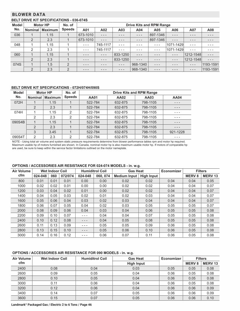
Landmark® Packaged Gas / Electric 2 to 6 Tons / Page 46
BLOWER DATABELT DRIVE KIT SPECIFICATIONS - 036-074SModel
No.Motor HP No. of
SpeedsDrive Kits and RPM Range
Nominal Maximum A01 A02 A03 A04 A05 A06 A07 A08036 1 1.15 1 673-1010 - - - - - - - - - 897-1346 - - - - - - - - -
2 2.3 1 673-1010 - - - - - - - - - 897-1346 - - - - - - - - -048 1 1.15 1 - - - 745-1117 - - - - - - - - - 1071-1429 - - - - - -
2 2.3 1 - - - 745-1117 - - - - - - - - - 1071-1429 - - - - - -060 1 1.15 1 - - - - - - 833-1250 - - - - - - - - - 1212-1548 - - -
2 2.3 1 - - - - - - 833-1250 - - - - - - - - - 1212-1548 - - -074S 1 1.5 2 - - - - - - - - - 968-1340 - - - - - - - - - 1193-1591
2 2.3 2 - - - - - - - - - 968-1340 - - - - - - - - - 1193-1591
OPTIONS / ACCESSORIES AIR RESISTANCE FOR 024-074 MODELS - in. w.g. Air Volume
cfmWet Indoor Coil Humiditrol Coil Gas Heat Economizer Filters
024-048 060 072/074 024-048 060, 074 Medium Input High Input MERV 8 MERV 13800 0.01 0.01 0.01 0.00 0.00 0.02 0.02 0.04 0.04 0.05
1000 0.02 0.02 0.01 0.00 0.00 0.02 0.02 0.04 0.04 0.071200 0.03 0.04 0.02 0.01 0.00 0.02 0.02 0.04 0.04 0.071400 0.04 0.05 0.03 0.02 0.01 0.02 0.03 0.04 0.04 0.071600 0.05 0.06 0.04 0.03 0.02 0.03 0.04 0.04 0.04 0.071800 0.06 0.07 0.05 0.04 0.02 0.03 0.05 0.05 0.05 0.072000 0.08 0.09 0.06 0.04 0.03 0.04 0.06 0.05 0.05 0.082200 0.09 0.10 0.07 - - - 0.04 0.04 0.07 0.05 0.05 0.082400 0.10 0.12 0.08 - - - 0.04 0.05 0.08 0.05 0.05 0.082600 0.11 0.13 0.09 - - - 0.05 0.05 0.09 0.06 0.05 0.082800 0.13 0.15 0.10 - - - 0.05 0.06 0.10 0.06 0.05 0.083000 0.14 0.16 0.12 - - - 0.06 0.07 0.11 0.06 0.05 0.08
BELT DRIVE KIT SPECIFICATIONS - 072H/074H/090SModel
No.Motor HP No. of
SpeedsDrive Kits and RPM Range
Nominal Maximum AA01 AA02 AA03 AA04072H 1 1.15 1 522-784 632-875 798-1105 - - -
2 2.3 1 522-784 632-875 798-1105 - - -074H 1 1.15 2 522-784 632-875 798-1105 - - -
2 2.3 2 522-784 632-875 798-1105 - - -090S4B 1 1.15 1 522-784 632-875 798-1105 - - -
2 2.3 1 522-784 632-875 798-1105 - - -3 3.45 1 522-784 632-875 798-1105 921-1228
090S4T 2 2.3 2 522-784 632-875 798-1105 - - -NOTE - Using total air volume and system static pressure requirements determine from blower performance tables rpm and motor hp required. Maximum usable hp of motors furnished are shown. In Canada, nominal motor hp is also maximum usable motor hp. If motors of comparable hp are used, be sure to keep within the service factor limitations outlined on the motor nameplate.
OPTIONS / ACCESSORIES AIR RESISTANCE FOR 090 MODELS - in. w.g. Air Volume
cfmWet Indoor Coil Humiditrol Coil Gas Heat Economizer Filters
High Input MERV 8 MERV 132400 0.08 0.04 0.03 0.05 0.05 0.082600 0.09 0.05 0.04 0.06 0.05 0.082800 0.10 0.05 0.04 0.06 0.05 0.083000 0.11 0.06 0.04 0.06 0.05 0.083200 0.12 0.06 0.04 0.06 0.06 0.093400 0.14 0.07 0.05 0.06 0.06 0.093600 0.15 0.07 0.05 0.06 0.06 0.10
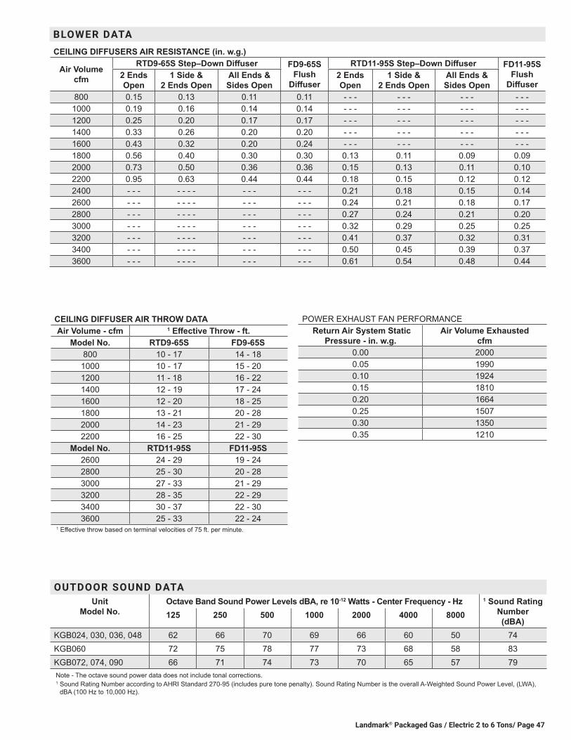
Landmark® Packaged Gas / Electric 2 to 6 Tons/ Page 47
BLOWER DATA CEILING DIFFUSERS AIR RESISTANCE (in. w.g.)
Air Volume cfm
RTD9-65S Step–Down Diffuser FD9-65S Flush
Diffuser
RTD11-95S Step–Down Diffuser FD11-95S Flush
Diffuser2 Ends Open
1 Side & 2 Ends Open
All Ends & Sides Open
2 Ends Open
1 Side & 2 Ends Open
All Ends & Sides Open
800 0.15 0.13 0.11 0.11 - - - - - - - - - - - -1000 0.19 0.16 0.14 0.14 - - - - - - - - - - - -1200 0.25 0.20 0.17 0.17 - - - - - - - - - - - -1400 0.33 0.26 0.20 0.20 - - - - - - - - - - - -1600 0.43 0.32 0.20 0.24 - - - - - - - - - - - -1800 0.56 0.40 0.30 0.30 0.13 0.11 0.09 0.092000 0.73 0.50 0.36 0.36 0.15 0.13 0.11 0.102200 0.95 0.63 0.44 0.44 0.18 0.15 0.12 0.122400 - - - - - - - - - - - - - 0.21 0.18 0.15 0.142600 - - - - - - - - - - - - - 0.24 0.21 0.18 0.172800 - - - - - - - - - - - - - 0.27 0.24 0.21 0.203000 - - - - - - - - - - - - - 0.32 0.29 0.25 0.253200 - - - - - - - - - - - - - 0.41 0.37 0.32 0.313400 - - - - - - - - - - - - - 0.50 0.45 0.39 0.373600 - - - - - - - - - - - - - 0.61 0.54 0.48 0.44
CEILING DIFFUSER AIR THROW DATAAir Volume - cfm 1 Effective Throw - ft.
Model No. RTD9-65S FD9-65S800 10 - 17 14 - 18
1000 10 - 17 15 - 201200 11 - 18 16 - 221400 12 - 19 17 - 241600 12 - 20 18 - 251800 13 - 21 20 - 282000 14 - 23 21 - 292200 16 - 25 22 - 30
Model No. RTD11-95S FD11-95S2600 24 - 29 19 - 242800 25 - 30 20 - 283000 27 - 33 21 - 293200 28 - 35 22 - 293400 30 - 37 22 - 303600 25 - 33 22 - 24
1 Effective throw based on terminal velocities of 75 ft. per minute.
POWER EXHAUST FAN PERFORMANCE Return Air System Static
Pressure - in. w.g. Air Volume Exhausted
cfm0.00 20000.05 19900.10 19240.15 18100.20 16640.25 15070.30 13500.35 1210
OUTDOOR SOUND DATAUnit
Model No.Octave Band Sound Power Levels dBA, re 10-12 Watts - Center Frequency - Hz 1 Sound Rating
Number (dBA)
125 250 500 1000 2000 4000 8000
KGB024, 030, 036, 048 62 66 70 69 66 60 50 74KGB060 72 75 78 77 73 68 58 83KGB072, 074, 090 66 71 74 73 70 65 57 79Note - The octave sound power data does not include tonal corrections.1 Sound Rating Number according to AHRI Standard 270-95 (includes pure tone penalty). Sound Rating Number is the overall A-Weighted Sound Power Level, (LWA),
dBA (100 Hz to 10,000 Hz).

Landmark® Packaged Gas / Electric 2 to 6 Tons / Page 48
ELECTRICAL DATA DIRECT DRIVE ECM - 2 TON | 2.5 TON ECMModel No. KGB024S4E KGB030S4E
1 Voltage - 60hz 208/230V - 1 Ph 208/230V - 1 PhCompressor Rated Load Amps 10.9 13.5
Locked Rotor Amps 60 73Outdoor Fan Motor
Full Load Amps 1.7 1.7
Service Outlet 115V GFI (amps) 15 15Indoor Blower Motor
Horsepower 0.33 0.33Type Direct (ECM) Direct (ECM)
Full Load Amps 2.9 2.92 Maximum
Overcurrent Protection
Unit Only 25 30
3 Minimum Circuit Ampacity
Unit Only 19 22
ELECTRICAL ACCESSORIES
Disconnect Standard Access 20W17 20W17Hinged Access 20W23 20W23
NOTE - All units have a minimum Short Circuit Current Rating (SCCR) of 5000 amps. 1 Extremes of operating range are plus and minus 10% of line voltage.2 HACR type breaker or fuse.3 Refer to National or Canadian Electrical Code manual to determine wire, fuse and disconnect size requirements.
ELECTRICAL DATA DIRECT DRIVE ECM - 3 TON | 4 TON | 5 TONModel No. KGB036S4E KGB048S4E KGB060S4E
1 Voltage - 60hz 208/230V - 1 Ph 208/230V - 1 Ph 208/230V - 1 PhCompressor Rated Load Amps 15.3 20 24.4
Locked Rotor Amps 70 99 144Outdoor Fan Motor
Full Load Amps 1.7 1.7 1.65
Power Exhaust (1) 0.33 HP
Full Load Amps 2.4 2.4 2.4
Service Outlet 115V GFI (amps) 15 15 15Indoor Blower Motor
Horsepower 0.50 0.75 1.0Type Direct (ECM) Direct (ECM) Direct (ECM)
Full Load Amps 4.6 6.3 8.42 Maximum
Overcurrent Protection
Unit Only 40 50 60with (1) 0.33 HP Power Exhaust
40 50 60
3 Minimum Circuit Ampacity
Unit Only 26 33 41with (1) 0.33 HP Power Exhaust
28 36 43
ELECTRICAL ACCESSORIES
Disconnect Standard Access 20W17 20W17 22A22Hinged Access 20W23 20W23 22A25
NOTE - All units have a minimum Short Circuit Current Rating (SCCR) of 5000 amps. 1 Extremes of operating range are plus and minus 10% of line voltage.2 HACR type breaker or fuse.3 Refer to National or Canadian Electrical Code manual to determine wire, fuse and disconnect size requirements.

Landmark® Packaged Gas / Electric 2 to 6 Tons/ Page 49
ELECTRICAL DATA DIRECT DRIVE PSC - 4 TONKGB048S4D - STANDARD EFFICIENCY - DIRECT DRIVE PSC BLOWER
1 Voltage - 60hz 208/230V - 3 Ph 460V - 3 Ph 575V - 3 PhCompressor Rated Load Amps 11 5.5 4.7
Locked Rotor Amps 86 37 34Outdoor Fan Motor
Full Load Amps 1.7 1.1 0.7
Power Exhaust (1) 0.33 HP
Full Load Amps 2.4 1.3 1
Service Outlet 115V GFI (amps) 15 1.3 1Indoor Blower Motor
Horsepower 0.5 0.5 0.5Type Direct (PSC) Direct (PSC) Direct (PSC)
Full Load Amps 3.9 2 22 Maximum
Overcurrent Protection
Unit Only 30 15 15with (1) 0.33 HP Power Exhaust
30 15 15
3 Minimum Circuit Ampacity
Unit Only 20 10 9with (1) 0.33 HP Power Exhaust
22 12 10
ELECTRICAL ACCESSORIES
Disconnect Standard Access 20W17 20W17 20W17Hinged Access 20W23 20W23 20W23
NOTE - All units have a minimum Short Circuit Current Rating (SCCR) of 5000 amps. 1 Extremes of operating range are plus and minus 10% of line voltage.2 HACR type breaker or fuse.3 Refer to National or Canadian Electrical Code manual to determine wire, fuse and disconnect size requirements.
ELECTRICAL DATA DIRECT DRIVE PSC - 3 TONModel No. KGB036S4D
1 Voltage - 60hz 208/230V - 3 Ph 460V - 3 Ph 575V - 3 PhCompressor Rated Load Amps 8.7 4 3.6
Locked Rotor Amps 70 31 27Outdoor Fan Motor
Full Load Amps 1.7 1.1 0.7
Power Exhaust (1) 0.33 HP
Full Load Amps 2.4 1.3 1
Service Outlet 115V GFI (amps) 15 15 20Indoor Blower Motor
Horsepower 0.5 0.5 0.5Type Direct (PSC) Direct (PSC) Direct (PSC)
Full Load Amps 3.9 2 22 Maximum
Overcurrent Protection
Unit Only 25 15 15with (1) 0.33 HP Power Exhaust
25 15 15
3 Minimum Circuit Ampacity
Unit Only 17 9 8with (1) 0.33 HP Power Exhaust
19 10 9
ELECTRICAL ACCESSORIES
Disconnect Standard Access 20W17 20W17 20W17Hinged Access 20W23 20W23 20W23
NOTE - All units have a minimum Short Circuit Current Rating (SCCR) of 5000 amps. 1 Extremes of operating range are plus and minus 10% of line voltage.2 HACR type breaker or fuse.3 Refer to National or Canadian Electrical Code manual to determine wire, fuse and disconnect size requirements.

Landmark® Packaged Gas / Electric 2 to 6 Tons / Page 50
ELECTRICAL DATA DIRECT DRIVE PSC - 5 TONModel No. KGB060S4D
1 Voltage - 60hz 208/230V - 3 Ph 460V - 3 Ph 575V - 3 PhCompressor Rated Load Amps 16 7.8 5.7
Locked Rotor Amps 110 52 38.9Outdoor Fan Motor
Full Load Amps 1.65 0.8 1
Power Exhaust (1) 0.33 HP
Full Load Amps 2.4 1.3 1
Service Outlet 115V GFI (amps) 15 15 20Indoor Blower Motor
Horsepower 0.75 0.75 0.75Type Direct (PSC) Direct (PSC) Direct (PSC)
Full Load Amps 4.9 2.5 2.52 Maximum
Overcurrent Protection
Unit Only 40 20 15with (1) 0.33 HP Power Exhaust
40 20 15
3 Minimum Circuit Ampacity
Unit Only 27 14 10with (1) 0.33 HP Power Exhaust
29 15 12
ELECTRICAL ACCESSORIES
Disconnect Standard Access 22A22 22A22 22A22Hinged Access 22A25 22A25 22A25
NOTE - All units have a minimum Short Circuit Current Rating (SCCR) of 5000 amps. 1 Extremes of operating range are plus and minus 10% of line voltage.2 HACR type breaker or fuse.3 Refer to National or Canadian Electrical Code manual to determine wire, fuse and disconnect size requirements.
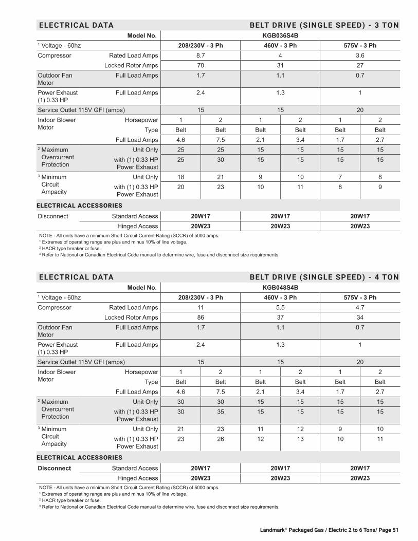
Landmark® Packaged Gas / Electric 2 to 6 Tons/ Page 51
ELECTRICAL DATA BELT DRIVE (SINGLE SPEED) - 3 TONModel No. KGB036S4B
1 Voltage - 60hz 208/230V - 3 Ph 460V - 3 Ph 575V - 3 PhCompressor Rated Load Amps 8.7 4 3.6
Locked Rotor Amps 70 31 27Outdoor Fan Motor
Full Load Amps 1.7 1.1 0.7
Power Exhaust (1) 0.33 HP
Full Load Amps 2.4 1.3 1
Service Outlet 115V GFI (amps) 15 15 20Indoor Blower Motor
Horsepower 1 2 1 2 1 2Type Belt Belt Belt Belt Belt Belt
Full Load Amps 4.6 7.5 2.1 3.4 1.7 2.72 Maximum
Overcurrent Protection
Unit Only 25 25 15 15 15 15with (1) 0.33 HP Power Exhaust
25 30 15 15 15 15
3 Minimum Circuit Ampacity
Unit Only 18 21 9 10 7 8with (1) 0.33 HP Power Exhaust
20 23 10 11 8 9
ELECTRICAL ACCESSORIES
Disconnect Standard Access 20W17 20W17 20W17Hinged Access 20W23 20W23 20W23
NOTE - All units have a minimum Short Circuit Current Rating (SCCR) of 5000 amps. 1 Extremes of operating range are plus and minus 10% of line voltage.2 HACR type breaker or fuse.3 Refer to National or Canadian Electrical Code manual to determine wire, fuse and disconnect size requirements.
ELECTRICAL DATA BELT DRIVE (SINGLE SPEED) - 4 TONModel No. KGB048S4B
1 Voltage - 60hz 208/230V - 3 Ph 460V - 3 Ph 575V - 3 PhCompressor Rated Load Amps 11 5.5 4.7
Locked Rotor Amps 86 37 34Outdoor Fan Motor
Full Load Amps 1.7 1.1 0.7
Power Exhaust (1) 0.33 HP
Full Load Amps 2.4 1.3 1
Service Outlet 115V GFI (amps) 15 15 20Indoor Blower Motor
Horsepower 1 2 1 2 1 2Type Belt Belt Belt Belt Belt Belt
Full Load Amps 4.6 7.5 2.1 3.4 1.7 2.72 Maximum
Overcurrent Protection
Unit Only 30 30 15 15 15 15with (1) 0.33 HP Power Exhaust
30 35 15 15 15 15
3 Minimum Circuit Ampacity
Unit Only 21 23 11 12 9 10with (1) 0.33 HP Power Exhaust
23 26 12 13 10 11
ELECTRICAL ACCESSORIES
Disconnect Standard Access 20W17 20W17 20W17Hinged Access 20W23 20W23 20W23
NOTE - All units have a minimum Short Circuit Current Rating (SCCR) of 5000 amps. 1 Extremes of operating range are plus and minus 10% of line voltage.2 HACR type breaker or fuse.3 Refer to National or Canadian Electrical Code manual to determine wire, fuse and disconnect size requirements.
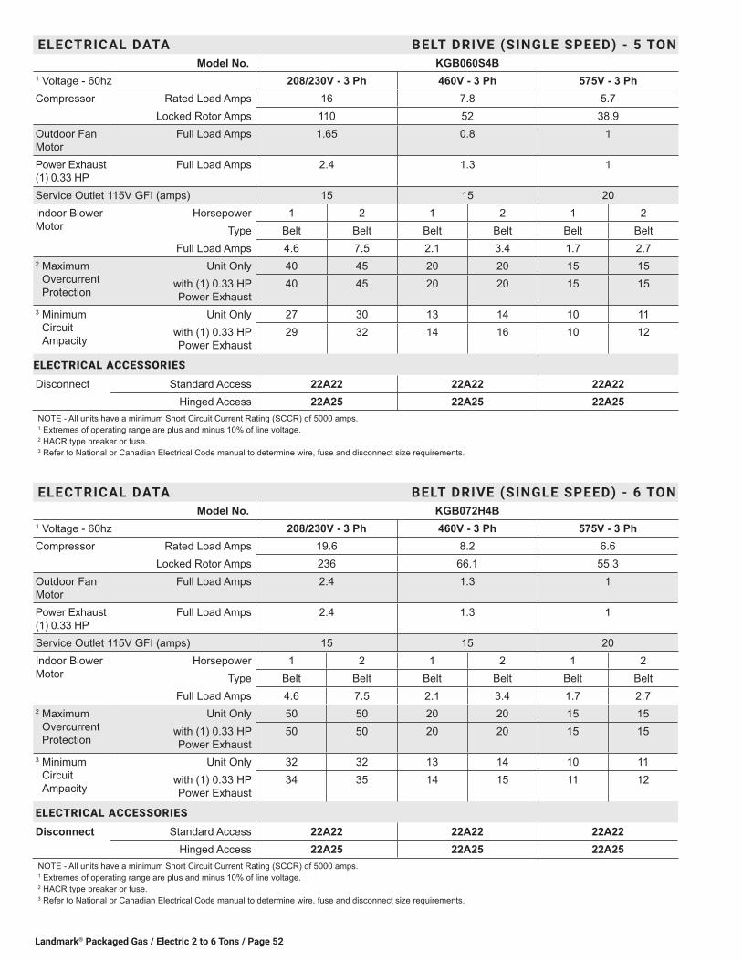
Landmark® Packaged Gas / Electric 2 to 6 Tons / Page 52
ELECTRICAL DATA BELT DRIVE (SINGLE SPEED) - 5 TONModel No. KGB060S4B
1 Voltage - 60hz 208/230V - 3 Ph 460V - 3 Ph 575V - 3 PhCompressor Rated Load Amps 16 7.8 5.7
Locked Rotor Amps 110 52 38.9Outdoor Fan Motor
Full Load Amps 1.65 0.8 1
Power Exhaust (1) 0.33 HP
Full Load Amps 2.4 1.3 1
Service Outlet 115V GFI (amps) 15 15 20Indoor Blower Motor
Horsepower 1 2 1 2 1 2Type Belt Belt Belt Belt Belt Belt
Full Load Amps 4.6 7.5 2.1 3.4 1.7 2.72 Maximum
Overcurrent Protection
Unit Only 40 45 20 20 15 15with (1) 0.33 HP Power Exhaust
40 45 20 20 15 15
3 Minimum Circuit Ampacity
Unit Only 27 30 13 14 10 11with (1) 0.33 HP Power Exhaust
29 32 14 16 10 12
ELECTRICAL ACCESSORIES
Disconnect Standard Access 22A22 22A22 22A22Hinged Access 22A25 22A25 22A25
NOTE - All units have a minimum Short Circuit Current Rating (SCCR) of 5000 amps. 1 Extremes of operating range are plus and minus 10% of line voltage.2 HACR type breaker or fuse.3 Refer to National or Canadian Electrical Code manual to determine wire, fuse and disconnect size requirements.
ELECTRICAL DATA BELT DRIVE (SINGLE SPEED) - 6 TONModel No. KGB072H4B
1 Voltage - 60hz 208/230V - 3 Ph 460V - 3 Ph 575V - 3 PhCompressor Rated Load Amps 19.6 8.2 6.6
Locked Rotor Amps 236 66.1 55.3Outdoor Fan Motor
Full Load Amps 2.4 1.3 1
Power Exhaust (1) 0.33 HP
Full Load Amps 2.4 1.3 1
Service Outlet 115V GFI (amps) 15 15 20Indoor Blower Motor
Horsepower 1 2 1 2 1 2Type Belt Belt Belt Belt Belt Belt
Full Load Amps 4.6 7.5 2.1 3.4 1.7 2.72 Maximum
Overcurrent Protection
Unit Only 50 50 20 20 15 15with (1) 0.33 HP Power Exhaust
50 50 20 20 15 15
3 Minimum Circuit Ampacity
Unit Only 32 32 13 14 10 11with (1) 0.33 HP Power Exhaust
34 35 14 15 11 12
ELECTRICAL ACCESSORIES
Disconnect Standard Access 22A22 22A22 22A22Hinged Access 22A25 22A25 22A25
NOTE - All units have a minimum Short Circuit Current Rating (SCCR) of 5000 amps. 1 Extremes of operating range are plus and minus 10% of line voltage.2 HACR type breaker or fuse.3 Refer to National or Canadian Electrical Code manual to determine wire, fuse and disconnect size requirements.
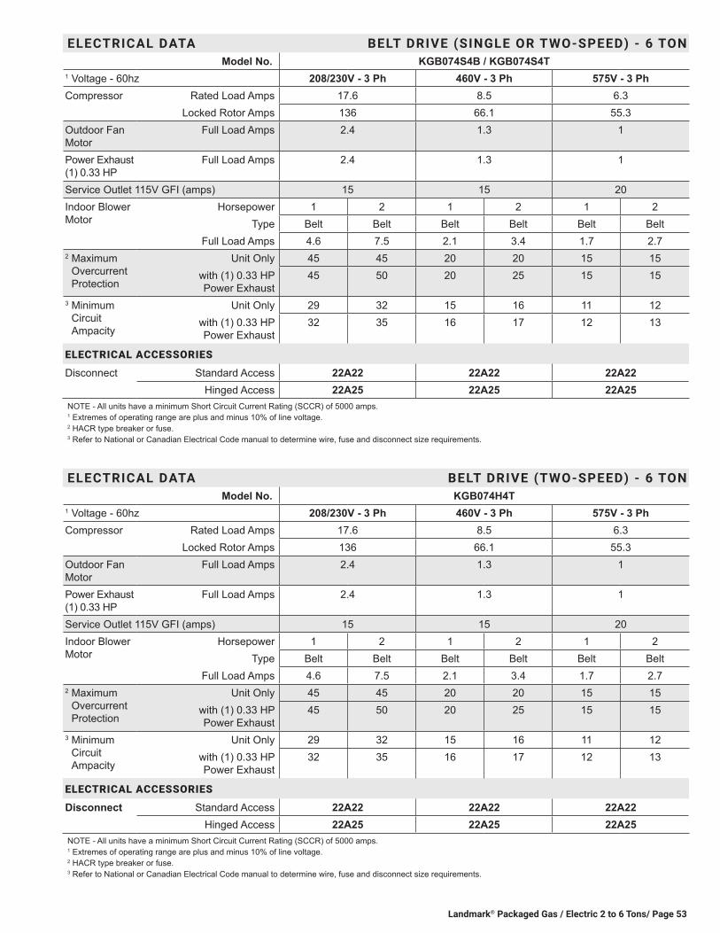
Landmark® Packaged Gas / Electric 2 to 6 Tons/ Page 53
ELECTRICAL DATA BELT DRIVE (TWO-SPEED) - 6 TONModel No. KGB074H4T
1 Voltage - 60hz 208/230V - 3 Ph 460V - 3 Ph 575V - 3 PhCompressor Rated Load Amps 17.6 8.5 6.3
Locked Rotor Amps 136 66.1 55.3Outdoor Fan Motor
Full Load Amps 2.4 1.3 1
Power Exhaust (1) 0.33 HP
Full Load Amps 2.4 1.3 1
Service Outlet 115V GFI (amps) 15 15 20Indoor Blower Motor
Horsepower 1 2 1 2 1 2Type Belt Belt Belt Belt Belt Belt
Full Load Amps 4.6 7.5 2.1 3.4 1.7 2.72 Maximum
Overcurrent Protection
Unit Only 45 45 20 20 15 15with (1) 0.33 HP Power Exhaust
45 50 20 25 15 15
3 Minimum Circuit Ampacity
Unit Only 29 32 15 16 11 12with (1) 0.33 HP Power Exhaust
32 35 16 17 12 13
ELECTRICAL ACCESSORIES
Disconnect Standard Access 22A22 22A22 22A22Hinged Access 22A25 22A25 22A25
NOTE - All units have a minimum Short Circuit Current Rating (SCCR) of 5000 amps. 1 Extremes of operating range are plus and minus 10% of line voltage.2 HACR type breaker or fuse.3 Refer to National or Canadian Electrical Code manual to determine wire, fuse and disconnect size requirements.
ELECTRICAL DATA BELT DRIVE (SINGLE OR TWO-SPEED) - 6 TONModel No. KGB074S4B / KGB074S4T
1 Voltage - 60hz 208/230V - 3 Ph 460V - 3 Ph 575V - 3 PhCompressor Rated Load Amps 17.6 8.5 6.3
Locked Rotor Amps 136 66.1 55.3Outdoor Fan Motor
Full Load Amps 2.4 1.3 1
Power Exhaust (1) 0.33 HP
Full Load Amps 2.4 1.3 1
Service Outlet 115V GFI (amps) 15 15 20Indoor Blower Motor
Horsepower 1 2 1 2 1 2Type Belt Belt Belt Belt Belt Belt
Full Load Amps 4.6 7.5 2.1 3.4 1.7 2.72 Maximum
Overcurrent Protection
Unit Only 45 45 20 20 15 15with (1) 0.33 HP Power Exhaust
45 50 20 25 15 15
3 Minimum Circuit Ampacity
Unit Only 29 32 15 16 11 12with (1) 0.33 HP Power Exhaust
32 35 16 17 12 13
ELECTRICAL ACCESSORIES
Disconnect Standard Access 22A22 22A22 22A22Hinged Access 22A25 22A25 22A25
NOTE - All units have a minimum Short Circuit Current Rating (SCCR) of 5000 amps. 1 Extremes of operating range are plus and minus 10% of line voltage.2 HACR type breaker or fuse.3 Refer to National or Canadian Electrical Code manual to determine wire, fuse and disconnect size requirements.

Landmark® Packaged Gas / Electric 2 to 6 Tons / Page 54
ELECTRICAL DATA BELT DRIVE (TWO-SPEED) - 7.5 TONModel No. KGB090S4T
1 Voltage - 60hz 208/230V - 3 Ph 460V - 3 Ph 575V - 3 PhCompressor Rated Load Amps 26.9 12 9
Locked Rotor Amps 164 94 65Outdoor Fan Motor
Full Load Amps 3 1.5 1.2
Power Exhaust (1) 0.33 HP
Full Load Amps 2.4 1.3 1
Service Outlet 115V GFI (amps) 15 15 20Indoor Blower Motor
Horsepower 2 2 2Type Belt Belt Belt
Full Load Amps 7.5 3.4 2.72 Maximum
Overcurrent Protection
Unit Only 70 30 20with (1) 0.33 HP Power Exhaust
70 30 25
3 Minimum Circuit Ampacity
Unit Only 45 20 16with (1) 0.33 HP Power Exhaust
47 22 17
ELECTRICAL ACCESSORIES
Disconnect Standard Access 22A22 22A22 22A22Hinged Access 22A25 22A25 22A25
NOTE - All units have a minimum Short Circuit Current Rating (SCCR) of 5000 amps.1 Extremes of operating range are plus and minus 10% of line voltage.2 HACR type breaker or fuse.3 Refer to National or Canadian Electrical Code manual to determine wire, fuse and disconnect size requirements.
ELECTRICAL DATA BELT DRIVE (SINGLE SPEED) - 7.5 TONModel No. KGB090S4B
1 Voltage - 60hz 208/230V - 3 Ph 460V - 3 Ph 575V - 3 PhCompressor Rated Load Amps 26.9 12 9
Locked Rotor Amps 164 94 65Outdoor Fan Motor
Full Load Amps 3 1.5 1.2
Power Exhaust (1) 0.33 HP
Full Load Amps 2.4 1.3 1
Service Outlet 115V GFI (amps) 15 15 20Indoor Blower Motor
Horsepower 1 2 3 1 2 3 1 2 3Type Belt Belt Belt Belt Belt Belt Belt Belt Belt
Full Load Amps 4.6 7.5 10.6 2.1 3.4 4.8 1.7 2.7 3.92 Maximum
Overcurrent Protection
Unit Only 60 70 70 30 30 30 20 20 25with (1) 0.33 HP Power Exhaust
70 7070
30 30 30 20 25 25
3 Minimum Circuit Ampacity
Unit Only 42 45 48 19 20 22 15 16 17with (1) 0.33 HP Power Exhaust
44 47 50 20 22 23 16 17 18
ELECTRICAL ACCESSORIES
Disconnect Standard Access - 0-22.5 kW 22A20 22A20 22A20 22A20 22A2030 kW 22A21 22A21 22A21 22A20 22A20
Hinged Access - 0-22.5 kW 22A23 22A23 22A23 22A23 22A2330 kW 22A24 22A24 22A24 22A23 22A23
NOTE - All units have a minimum Short Circuit Current Rating (SCCR) of 5000 amps.1 Extremes of operating range are plus and minus 10% of line voltage.2 HACR type breaker or fuse.3 Refer to National or Canadian Electrical Code manual to determine wire, fuse and disconnect size requirements.4 Factory installed circuit breaker not available.
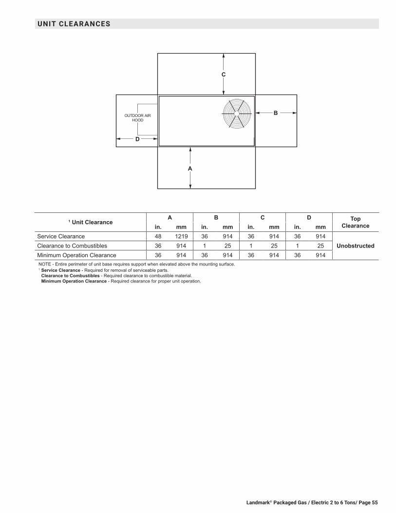
Landmark® Packaged Gas / Electric 2 to 6 Tons/ Page 55
B
D
C
A
OUTDOOR AIRHOOD
1 Unit ClearanceA B C D Top
Clearancein. mm in. mm in. mm in. mmService Clearance 48 1219 36 914 36 914 36 914
UnobstructedClearance to Combustibles 36 914 1 25 1 25 1 25Minimum Operation Clearance 36 914 36 914 36 914 36 914NOTE - Entire perimeter of unit base requires support when elevated above the mounting surface.1 Service Clearance - Required for removal of serviceable parts.
Clearance to Combustibles - Required clearance to combustible material. Minimum Operation Clearance - Required clearance for proper unit operation.
UNIT CLEARANCES

Landmark® Packaged Gas / Electric 2 to 6 Tons / Page 56
OPTIONS / ACCESSORIESShipping Weights
lbs. kgECONOMIZER / OUTDOOR AIR / EXHAUSTEconomizerEconomizer - Includes Barometric Relief Dampers and Exhaust Hood 131 59Outdoor Air DampersMotorized 40 18Manual 30 14Power ExhaustStandard Static 35 16
GAS HEATMedium Heat (adder over standard heat) 8 4High Heat (adder over standard heat) 19 9HUMIDITROL® DEHUMIDIFICATION SYSTEMHumiditrol Dehumidification Option (Net Weight) 27 12ROOF CURBSHybrid Roof Curbs, Downflow8 in. height 50 2314 in. height 70 3218 in. height 80 3624 in. height 100 45Hybrid Roof Curbs, Full Perimeter, Downflow8 in. height 57 2614 in. height 60 2718 in. height 91 4124 in. height 114 52Adjustable Pitch Curb, Downflow14 in. height 113 51
CEILING DIFFUSERSStep-Down RTD9-65S 80 36
RTD11-95S 118 54Flush FD9-65S 80 36
FD11-95S 118 54Transitions (Supply and Return) T1TRAN10AN1 22 10
T1TRAN20N-1 21 10
WEIGHT DATA
Model Number Outdoor Coil
Net Shipping Outdoor Coil
Net Shippinglbs. kg lbs. kg lbs. kg lbs. kg
024S Base Unit Environ™ 530 240 571 259 Fin/Tube 566 257 607 275024S Max. Unit Environ™ 640 290 681 309 Fin/Tube 700 318 741 336030S Base Unit Environ™ 533 242 574 260 Fin/Tube 569 258 610 277030S Max. Unit Environ™ 643 292 684 310 Fin/Tube 703 319 744 337036 Base Unit Environ™ 555 252 596 270 Fin/Tube 588 267 629 285036 Max. Unit Environ™ 701 318 742 337 Fin/Tube 761 345 802 364048 Base Unit Environ™ 555 252 596 270 Fin/Tube 588 267 629 285048 Max. Unit Environ™ 716 325 757 343 Fin/Tube 776 352 817 371060 Base Unit Environ™ 649 294 690 313 Fin/Tube 682 309 723 328060 Max. Unit Environ™ 813 369 854 387 Fin/Tube 873 396 914 415072, 074 Base Unit Environ™ 649 294 690 313 Fin/Tube ¹ 682 ¹ 309 ¹ 723 ¹ 328072, 074 Max. Unit Environ™ 813 369 854 387 Fin/Tube ¹ 873 ¹ 396 ¹ 914 ¹ 415090 Base Unit Environ™ 783 355 843 382 Fin/Tube 848 385 908 412090 Max. Unit Environ™ 883 401 953 432 Fin/Tube 975 442 1045 4741 074S models only.

Landmark® Packaged Gas / Electric 2 to 6 Tons/ Page 57
45(1143)
END VIEW
1 (25)
47 (1194)BASE
38-7
/8 (9
87) K
GB0
24 th
ru 0
4846
-7/8
(119
1) K
GB0
60, 0
72, 0
74 a
nd 0
90
18-3/8(467)
19-1/2(495)
5-1/2(140)
FORKLIFT SLOTS(Front, Back and
Blower End)
HORIZONTALRETURN AIR
OPENING(Without Economizer)
HORIZONTALSUPPLY AIR
OPENING
2 (51)
(279)
29(737)
20(508)
5-1/2(140)
BACK VIEW
11
DD CC
BBAA
FF
EE
11(279)
16-1/4(413)
18(457)
20(508)
5 (127)
47 (1194)BASE
BOTTOMSUPPLY
AIROPENING
TOP VIEW (Base)
CENTEROF
GRAVITY
9-1/2(241)
6-5/8(168)
26-1/2(673)
5-5/8(143)
29(737)
7 (178) BOTTOMRETURN
AIROPENING
BOTTOMCONDENSATE
OUTLET BOTTOM POWER ENTRY3 X 8 (76 X 203)
25-3/4 (654)KGB024 THRU 07438-3/4 (984) KGB090
GASINLET
FLUE/VENTOUTLET
27(686)
15(381)
3-1/2 (89)
26-1/2(673)
5-1/2(140)
LIFTING HOLES(For rigging)
SIDE VIEW
1 (25)
35-3
/8 (8
99) K
GB0
24 th
ru 0
4843
-3/8
(110
2) K
GB0
60, 0
72,
074
and
090
CONDENSATEOUTLET
(EITHER SIDE)
ELECTRICALINLET
85-1/4 (2165) KGB024 THRU KGB074 BASE98-1/4 (2496) KGB090 BASE
83-1/4 (2115) KGB024 THRU 07496-1/4 (2245) KGB090
DIMENSIONS - UNITModel
No.CORNER WEIGHTS CENTER OF GRAVITY
AA BB CC DD EE FFBase Max. Base Max. Base Max. Base Max. Base Max. Base Max.
lbs. kg lbs. kg lbs. kg lbs. kg lbs. kg lbs. kg lbs. kg lbs. kg in. mm in. mm in. mm in. mm024 107 49 129 59 124 56 132 60 160 73 170 77 138 63 208 95 39-1/2 1003 45 1143 20-1/2 521 20-1/2 521030 108 49 130 59 125 57 132 60 161 73 171 78 139 63 209 95 39-1/2 1003 45 1143 20-1/2 521 20-1/2 521036 112 51 142 64 130 59 141 64 168 76 190 86 145 66 228 104 39-1/2 1003 45 1143 20-1/2 521 20 508048 112 51 145 66 130 59 144 65 168 76 194 88 145 66 233 106 39-1/2 1003 45 1143 20-1/2 521 20 508060 130 59 162 74 147 67 167 76 198 90 226 103 175 79 257 117 40 1016 44 1118 20 508 20 508072 130 59 162 74 147 67 167 76 198 90 226 103 175 79 257 117 40 1016 44 1118 20 508 20 508074 130 59 162 74 147 67 167 76 198 90 226 103 175 79 257 117 40 1016 44 1118 20 508 20 508090 168 76 195 88 183 83 212 96 227 103 263 119 203 95 241 109 47 1194 47 1194 21 533 21 533
Base Unit - The unit with NO INTERNAL OPTIONS.Max. Unit - The unit with ALL INTERNAL OPTIONS Installed. (Economizer, Standard Static Power Exhaust Fans, Controls, etc.). Does not include accessories external to unit or high static power exhaust.

Landmark® Packaged Gas / Electric 2 to 6 Tons / Page 58
DIMENSIONS - ACCESSORIES
COMBINATION OUTDOOR AIR HOOD DETAIL FOR OPTIONAL ECONOMIZER AND BAROMETRIC RELIEF DAMPERS(Furnished With Economizer for Downflow Applications)
SIDE VIEW
OUTDOOR AIR DAMPER HOOD DETAIL (Downflow or Horizontal Applications)
MANUAL OUTDOOR AIR HOOD
SIDE VIEW
MOTORIZED OUTDOOR AIR HOOD
SIDE VIEW
OPTIONALCOMBINATION HOOD
(Furnished with Economizer)
OUTDOOR AIRDAMPER HOOD
OPTIONALOUTDOOR
AIR DAMPERSAND PANEL
OUTDOOR AIRDAMPER HOOD
(Furnished)
OUTDOOR AIRDAMPER HOOD
(Furnished)
OPTIONALOUTDOOR
AIR DAMPERSAND PANEL
OUTDOOR AIRDAMPER HOOD
16(406)
16-1/2(419)
35 (889)024 thru 04843 (1092)060 thru 090
13-1/2(343)
10-1/2(267)
10-1/2 (267)
16-3/8(416)
17-3/8(441)
35 (889)024 thru 04843 (1092)060 thru 090
35(889)
16-1/4(413)
16-3/8(416)
35(889)
16(406)
32(813)
33-1/4(845)
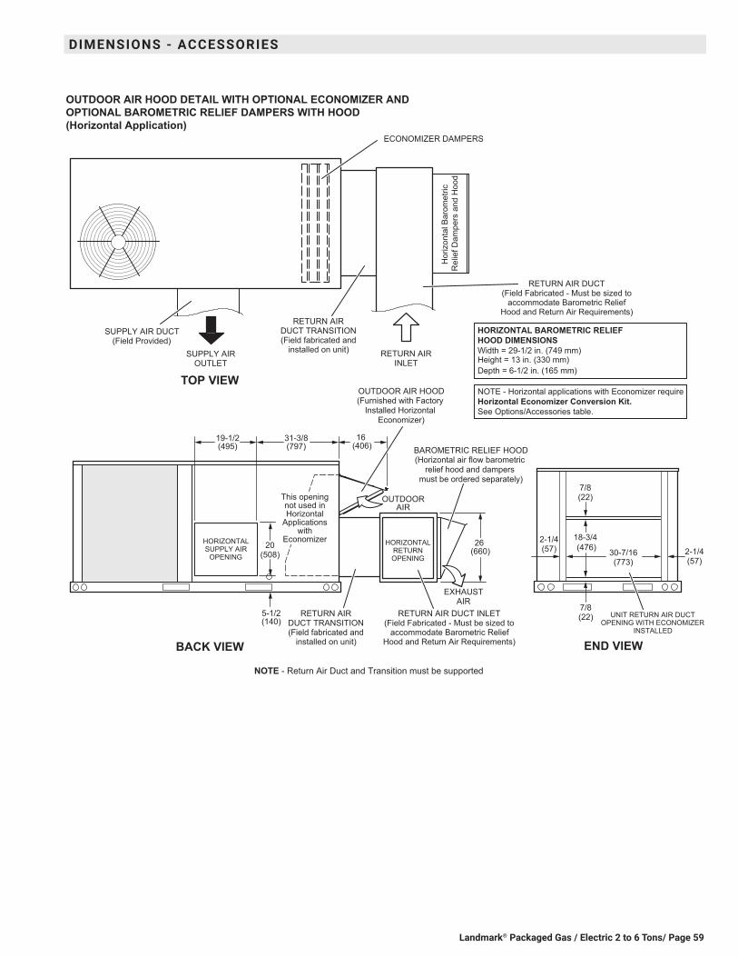
Landmark® Packaged Gas / Electric 2 to 6 Tons/ Page 59
DIMENSIONS - ACCESSORIES
UNIT RETURN AIR DUCTOPENING WITH ECONOMIZER
INSTALLED
END VIEW
NOTE - Return Air Duct and Transition must be supported
HORIZONTAL BAROMETRIC RELIEF HOOD DIMENSIONSWidth = 29-1/2 in. (749 mm)Height = 13 in. (330 mm)
SUPPLY AIR DUCT(Field Provided)
RETURN AIR DUCT(Field Fabricated - Must be sized to
accommodate Barometric ReliefHood and Return Air Requirements)
TOP VIEW
Hor
izon
tal B
arom
etric
R
elie
f Dam
pers
and
Hoo
d
RETURN AIRDUCT TRANSITION(Field fabricated and
installed on unit)
ECONOMIZER DAMPERS
RETURN AIRINLET
SUPPLY AIROUTLET
RETURN AIR DUCT INLET(Field Fabricated - Must be sized to
accommodate Barometric Relief Hood and Return Air Requirements)
BAROMETRIC RELIEF HOOD(Horizontal air flow barometric
relief hood and dampers must be ordered separately)
RETURN AIRDUCT TRANSITION(Field fabricated and
installed on unit)
OUTDOOR AIR HOOD(Furnished with Factory
Installed Horizontal Economizer)
BACK VIEW
EXHAUSTAIR
OUTDOORAIR
HORIZONTALSUPPLY AIR
OPENING
HORIZONTALRETURNOPENING
This openingnot used inHorizontal
Applicationswith
Economizer
NOTE - Horizontal applications with Economizer require Horizontal Economizer Conversion Kit.See Options/Accessories table.
OUTDOOR AIR HOOD DETAIL WITH OPTIONAL ECONOMIZER AND OPTIONAL BAROMETRIC RELIEF DAMPERS WITH HOOD(Horizontal Application)
Depth = 6-1/2 in. (165 mm)
2-1/4(57)
30-7/16(773)
7/8(22)
18-3/4 (476)
7/8(22)
2-1/4(57)
5-1/2(140)
19-1/2(495)
31-3/8(797)
16 (406)
20(508)
26 (660)

Landmark® Packaged Gas / Electric 2 to 6 Tons / Page 60
DIMENSIONS - ACCESSORIES
NOTE - Roof deck may be omitted within confines of curb.
TYPICAL FLASHING DETAIL FOR ROOF CURB
ROOF CURB(Extends around entire
perimeter of unit)
FIBERGLASSINSULATION
(Furnished)COUNTER FLASHING(Field Supplied)
BASE BOTTOM
RIGID INSULATION(Field Supplied)
ROOFINGMATERIAL
CANT STRIP(Field Supplied)
PACKAGEDUNIT
NAILER STRIP(Furnished)
DETAIL ROOF CURB
FACTORY INSTALLEDPERIMETER WOODNAILER STRIP
RETURNOPENING
SUPPLYOPENING
HYBRID ROOF CURBS - DOUBLE DUCT OPENING - STANDARD AND FULL PERIMETER
19-1/8(486)
15-1/8(384)
12-5/8(321)
1-3/4(44)
32(813)
21-1/8(537)
41-1/2(1054)
38(965)
8 (203)14 (356)18 (457)24 (610)
8 (203)14 (356)18 (457)24 (610)
1-3/4(44)
1/2 (13)
1-3/4(44)
A B
Model No.A B
in. mm in. mmStandard - 024, 030, 036, 048, 060, 072, 074 1 090 79-3/4 2026 76-1/4 1937Full Perimeter - 090 92-3/4 2356 89-1/4 22671 090 models can be used on smaller 79-3/4 in. (2026 mm) roof curbs (not full perimeter) with 15-3/4 in. (400 mm) overhang at condenser end of unit. See dimension drawing on page 53
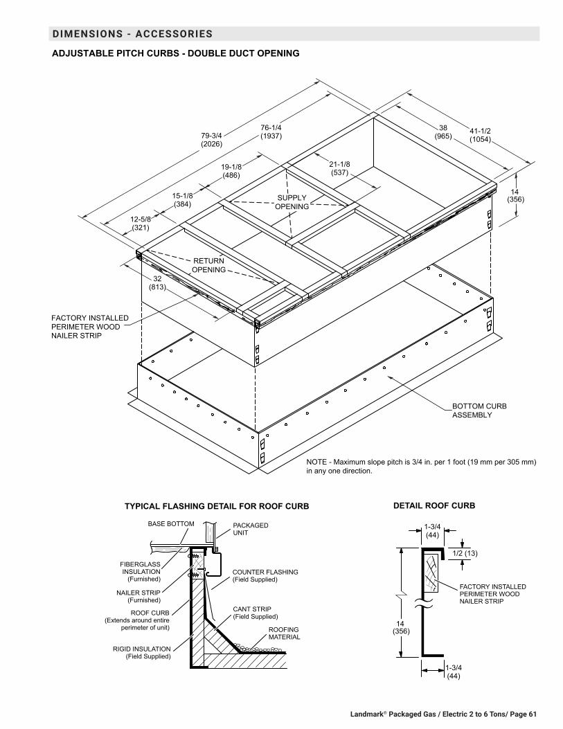
Landmark® Packaged Gas / Electric 2 to 6 Tons/ Page 61
DIMENSIONS - ACCESSORIES
TYPICAL FLASHING DETAIL FOR ROOF CURB
ROOF CURB(Extends around entire
perimeter of unit)
FIBERGLASSINSULATION
(Furnished)COUNTER FLASHING(Field Supplied)
BASE BOTTOM
RIGID INSULATION(Field Supplied)
ROOFINGMATERIAL
CANT STRIP(Field Supplied)
PACKAGEDUNIT
NAILER STRIP(Furnished)
DETAIL ROOF CURB
FACTORY INSTALLEDPERIMETER WOODNAILER STRIP
RETURNOPENING
ADJUSTABLE PITCH CURBS - DOUBLE DUCT OPENING
SUPPLYOPENING
FACTORY INSTALLEDPERIMETER WOODNAILER STRIP
BOTTOM CURBASSEMBLY
NOTE - Maximum slope pitch is 3/4 in. per 1 foot (19 mm per 305 mm)in any one direction.
19-1/8(486)
15-1/8(384)
12-5/8(321)
32(813)
21-1/8(537)
41-1/2(1054)
38(965)
14 (356)
1-3/4(44)
1/2 (13)
1-3/4(44)
76-1/4(1937)79-3/4
(2026)
14 (356)

Landmark® Packaged Gas / Electric 2 to 6 Tons / Page 62
090 MODELS - SHOWING OVERHANG ON SMALLER 79-3/4 INCH LENGTH ROOF CURBS(Not Full Perimeter)
79-3/4(2026)
15-3/4(400)
2-3/4(70)
SIDE VIEW
ROOF CURB
RET
UR
NO
PEN
ING
12(305) 31-1/2
(800)
8 (203)
18-1/2(470)
20-1/2(521)
8 (203)
RETURN TRANSITION
SUPPLY TRANSITION
TRANSITIONS
21-1/8(537)
SUPPLYOPENING
32(813)
T1TRAN10AN-1 - FOR 18 INCH (457 MM) DUCTT1TRAN20N-1 - FOR 20 INCH (508 MM) DUCT
T1TRAN10AN-1 - FOR 18 INCH (457 MM) DUCTT1TRAN20N-1 - FOR 20 INCH (508 MM) DUCT
12-5/8(321)
19-1/8(486)
1-1/2 inch (38 mm) T1TRAN10AN-12 inch (51mm) T1TRAN20N-1
1-1/2 inch (38 mm) T1TRAN10AN-12 inch (51mm) T1TRAN20N-1
DIMENSIONS - ACCESSORIES

Landmark® Packaged Gas / Electric 2 to 6 Tons/ Page 63
DIMENSIONS - ACCESSORIES
COMBINATION CEILING SUPPLY AND RETURN DIFFUSERSSTEP-DOWN CEILING DIFFUSER FLUSH CEILING DIFFUSER
L A
J
C
HH
DG
G
FE
B
K
2 (51)
A
C
HH
DG
G
FE
B
2 (51)
Model Number RTD9-65S RTD11-95SA in. 47-5/8 47-5/8
mm 1159 1159B in. 23-5/8 29-5/8
mm 600 752C in. 11-3/8 14-3/8
mm 289 365D in. 21-1/2 27-1/2
mm 546 699E in. 45-1/2 45-1/2
mm 1156 1158F in. 22-1/2 22-1/2
mm 572 572G in. 11-1/2 11-1/2
mm 292 292H in. 10-3/4 13-3/4
mm 273 349J in. 45-1/2 45-1/2
mm 1156 1156K in. 21-1/2 27-1/2
mm 546 699L in. 7-1/8 8-1/8
mm 181 206Duct Size in. 18 round 20 round
mm 457 round 508 round
Model Number FD9-65S FD11-95SA in. 47-5/8 47-5/8
mm 1159 1159B in. 23-5/8 29-5/8
mm 600 752C in. 13-1/2 16-5/8
mm 343 422D in. 21 27
mm 533 686E in. 45 45
mm 1143 1143F in. 22-1/2 22-1/2
mm 572 572G in. 11-1/4 11-1/4
mm 286 286H in. 10-1/2 13-1/2
mm 267 343Duct Size in. 18 round 20 round
mm 457 round 508 round

REVISIONS
REVISIONS
Sections Description of Change
Options/Accessories Added step-down transformers for UVC lights.Catalog numbers revised for:Barometric Relief DampersCondensate Drain TrapDisconnectsEconomizersLPG KitsPower ExhaustSingle EnthalpySmoke Detectors
NOTE - Due to Lennox’ ongoing commitment to quality, Specifications, Ratings and Dimensions subject to change without notice and without incurring liability. Improper installation, adjustment, alteration, service or maintenance can cause property damage or personal injury. Installation and service must be performed by a qualified installer and servicing agency. ©2021 Lennox Industries, Inc.
Visit us at www.Lennox.com For the latest technical information, www.LennoxCommercial.com Contact us at 1-800-4-LENNOX