Embed Size (px)
Citation preview
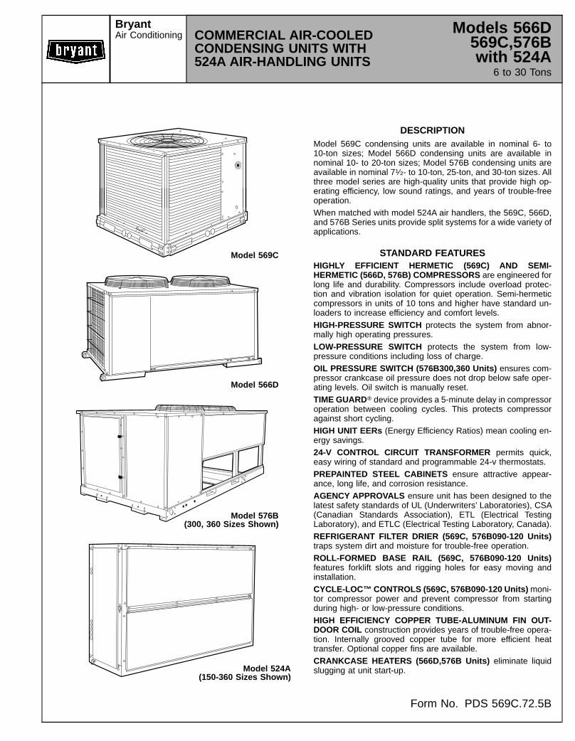
DESCRIPTIONModel 569C condensing units are available in nominal 6- to10-ton sizes; Model 566D condensing units are available innominal 10- to 20-ton sizes; Model 576B condensing units areavailable in nominal 71⁄2- to 10-ton, 25-ton, and 30-ton sizes. Allthree model series are high-quality units that provide high op-erating efficiency, low sound ratings, and years of trouble-freeoperation.When matched with model 524A air handlers, the 569C, 566D,and 576B Series units provide split systems for a wide variety ofapplications.
STANDARD FEATURESHIGHLY EFFICIENT HERMETIC (569C) AND SEMI-HERMETIC (566D, 576B) COMPRESSORS are engineered forlong life and durability. Compressors include overload protec-tion and vibration isolation for quiet operation. Semi-hermeticcompressors in units of 10 tons and higher have standard un-loaders to increase efficiency and comfort levels.HIGH-PRESSURE SWITCH protects the system from abnor-mally high operating pressures.LOW-PRESSURE SWITCH protects the system from low-pressure conditions including loss of charge.OIL PRESSURE SWITCH (576B300,360 Units) ensures com-pressor crankcase oil pressure does not drop below safe oper-ating levels. Oil switch is manually reset.TIME GUARDT device provides a 5-minute delay in compressoroperation between cooling cycles. This protects compressoragainst short cycling.HIGH UNIT EERs (Energy Efficiency Ratios) mean cooling en-ergy savings.24-V CONTROL CIRCUIT TRANSFORMER permits quick,easy wiring of standard and programmable 24-v thermostats.PREPAINTED STEEL CABINETS ensure attractive appear-ance, long life, and corrosion resistance.AGENCY APPROVALS ensure unit has been designed to thelatest safety standards of UL (Underwriters’ Laboratories), CSA(Canadian Standards Association), ETL (Electrical TestingLaboratory), and ETLC (Electrical Testing Laboratory, Canada).REFRIGERANT FILTER DRIER (569C, 576B090-120 Units)traps system dirt and moisture for trouble-free operation.ROLL-FORMED BASE RAIL (569C, 576B090-120 Units)features forklift slots and rigging holes for easy moving andinstallation.CYCLE-LOC™CONTROLS (569C, 576B090-120 Units) moni-tor compressor power and prevent compressor from startingduring high- or low-pressure conditions.HIGH EFFICIENCY COPPER TUBE-ALUMINUM FIN OUT-DOOR COIL construction provides years of trouble-free opera-tion. Internally grooved copper tube for more efficient heattransfer. Optional copper fins are available.CRANKCASE HEATERS (566D,576B Units) eliminate liquidslugging at unit start-up.
Model 569C
Model 566D
Model 576B(300, 360 Sizes Shown)
Model 524A(150-360 Sizes Shown)
BryantAir Conditioning COMMERCIAL AIR-COOLED
CONDENSING UNITS WITH524A AIR-HANDLING UNITS
Models 566D569C,576Bwith 524A
6 to 30 Tons
Form No. PDS 569C.72.5B

FIELD-INSTALLED ACCESSORYDESCRIPTION AND USAGE
Gage Panel — Package includes suction and head pressuregages, mounting bracket, fittings, and hardware.SUGGESTED USE:• When easy and quick reading of system operating pressuresis desired.
Low Ambient Kit — Kit consists of electronic control andcondenser-coil temperature sensor to regulate the condenserfan motor in order to maintain condenser-coil head pressure forproper cooling operation.SUGGESTED USE:• Whenever cooling is required at low outdoor ambient tem-peratures (as low as –20 F).
Winter-Start Relay Package — Package consists oftime-delay.SUGGESTED USE:• For timed bypass of low-pressure switch on start-up duringlow ambient conditions. (Not required for 576B300,360 units.)
Thermostat and Subbase — Accessories consist of a tem-perature regulating device with a separate mounting support.SUGGESTED USE:• For cooling control of condensing unit.Condenser Coil Guard Assembly (569C, 576B090-120, 566DUnits) — Package consists of a coil grille which attaches to thecondenser coil.SUGGESTED USE:• To protect the condenser coil from damage by large objects orvandalism.
Condenser Coil Hail Guard Assembly (569C, 576B090-120Units) — Package consists of a hood and coil grille which at-tach to the condenser coil.SUGGESTED USE:• To protect the condenser coil from hail and other debris.Pressure-Operating Unloader (566D120-180 Units) — Pack-age includes cylinder head, valve plate, unloader valve, andhardware.SUGGESTED USE:• To add additional step of unloading. Provides maximum com-fort and energy efficiency at partial loads.
Electric Solenoid Unloader Conversion Package (576B120,566D, and 576B300,360 Units) — Accessory consists of un-loader valve, piston, and hardware. Note that coil is sold as aseparate accessory.SUGGESTED USE:• To convert any pressure-operated unloader to electricunloading.
Hot Gas Bypass Kit (576B300,360 Units) — Accessory con-tains valve and hardware to maintain constant suction pressure.SUGGESTED USE:• To prevent the indoor coil from freezing during low airflow orlow return air temperature conditions.
Part Winding Start Relay (576B300,360 Units) — Accessoryreduces inrush current and locked rotor amps during unitstart-up.SUGGESTED USE:• On 208/230 V, 3 Ph, 60 Hz units only, reduces start-up loads.
CONTENTSPage
Model Descriptions . . . . . . . . . . . . . . . . . . . . . . . . . . . . . . . 4,5ARI Capacities . . . . . . . . . . . . . . . . . . . . . . . . . . . . . . . . . . . 6Dimensional Drawings . . . . . . . . . . . . . . . . . . . . . . . . . . . 7-12Specifications . . . . . . . . . . . . . . . . . . . . . . . . . . . . . . . . . . 13-15Selection Procedure . . . . . . . . . . . . . . . . . . . . . . . . . . . . . . 16Condensing Unit Ratings — 569C Units . . . . . . . . . . . . . . 17Condensing Unit Ratings — 576B090-120 Units . . . . . . . . 17Condensing Unit Ratings — 566D Units . . . . . . . . . . . . . . 18Condensing Unit Ratings — 576B300,360 Units . . . . . . . . 18Combination Ratings — 569C Units . . . . . . . . . . . . . . . . 19,20Combination Ratings — 576B090-120 Units . . . . . . . . . . 20,21Combination Ratings — 566D Units . . . . . . . . . . . . . . . . 22,23Combination Ratings — 576B300,360 Units . . . . . . . . . . . 24Hydronic Heating Capacities — 524A . . . . . . . . . . . . . . . . 25Air Delivery — 524A . . . . . . . . . . . . . . . . . . . . . . . . . . . . 26-29Accessory Pressure Drop — 524A . . . . . . . . . . . . . . . . . . . 29Accessory Plenum Air Throw Data — 524A Units . . . . . . . 29Electrical Data . . . . . . . . . . . . . . . . . . . . . . . . . . . . . . . . . 30-32Electric Heater Data — 524A Units . . . . . . . . . . . . . . . . . . 33Operating Sequences . . . . . . . . . . . . . . . . . . . . . . . . . . . . . 34Typical Field Wiring . . . . . . . . . . . . . . . . . . . . . . . . . . . . . 35-38Typical Installations . . . . . . . . . . . . . . . . . . . . . . . . . . . . . 39-43Application Data — 569C, 576B090-120 Units . . . . . . . . . 44Application Data — 566D Units . . . . . . . . . . . . . . . . . . . . 45,46Application Data — 576B300,360 Units . . . . . . . . . . . . . . . 47Application Data — 524A Units . . . . . . . . . . . . . . . . . . . . 48-50Engineer’s Specification Guide —569C, 576B090-120 Units . . . . . . . . . . . . . . . . . . . . . . . . 51
Engineer’s Specification Guide — 566D Units . . . . . . . . . . 52Engineer’s Specification Guide — 576B300,360 Units . . . 53Engineer’s Specification Guide — 524A Units . . . . . . . . . . 54
2

524A AIR-HANDLING UNIT STANDARD FEATURESMULTIPOISE DESIGN can be installed horizontally or verticallywithout modification. Accessory suspension packages and sub-bases are available for floor or ceiling mounting. Coil connectionaccess is provided on both sides of the unit, and drain connec-tions are provided for both horizontal and verticalapplications.INDOOR AIR QUALITY is promoted by cleanable insulationtreated with an EPA-registered antimicrobial agent, 2-in. deepfilters, and sloped drain pans. When used with an accessoryCO2 sensor, the economizer accessory can be used to admitextra fresh air into the building if necessary.RUGGED DEPENDABILITY is provided by the die-formed gal-vanized steel casings, galvanized steel internal components (in-cluding fan scrolls and coil casings) and mechanically bondedcoil fins.EASIER INSTALLATION AND SERVICE help you to get theunit installed and running quickly. The direct expansion (DX)coils have thermostatic expansion valves (TXVs) with matchingdistributor nozzles. Units can be converted from horizontal tovertical operation by simply repositioning the unit. Drain panconnections are duplicated on both sides of the unit, and drainpans can be pitched for right- or left-hand operation with asimple adjustment. The fan motor and fan contactor areprewired. The filters, motor, drive, TXVs, and coil connectionsare all easily accessed by removing a single side panel.ECONOMICAL OPERATION saves money by reducing instal-lation expense and providing ongoing energy-efficient perfor-mance. Coils have mechanically bonded fins for improved heattransfer. The high efficiency, precision-balanced fans minimizesurging and unbalanced operation to reduce operating ex-penses. When the outside air enthalpy is suitable, the econo-mizer accessory can admit outside air to provide ‘‘free’’ cooling.Accessory hot water and steam coils and electric heaters aremounted directly on the fan deck for easy installation.
524A FACTORY-INSTALLED OPTION DESCRIPTIONAND USAGE
Alternate Fan Motors and Drives are available to provide thewidest possible range of performance. In addition to the drivesupplied for standard static pressure applications, drives for me-dium and high static applications are also available. An alternatemotor is also available for use with the high-static drive.Prepainted Steel Units are available from the factory for appli-cations that require painted units. Units are painted with Ameri-can Sterling Gray color.
524A FIELD-INSTALLED ACCESSORY DESCRIPTIONAND USAGE
Two-Row Hot Water Coils have 5⁄8-in. diameter copper tubesmechanically bonded to aluminum plate fins. The coils havenon-ferrous headers.One-Row Steam Coil has 1-in. OD copper tube and aluminumfins. The Inner Distributing Tube (IDT) design provides uniformtemperatures across the coil face. The steam coil has a broadoperating pressure range; up to 175 psig at 400 F. IDT steamcoils are especially suited to applications where sub-freezing airenters the unit.Electric Resistance Heat Coil has a multi-stage, open-wire de-sign and is mounted in a rigid frame. Safety cutouts for hightemperature conditions are standard.Economizer (Enthalpy Controlled) provides ventilation airand provides ‘‘free’’ cooling if outside ambient temperature andhumidity are suitable. Can also be used in conjunction with ther-mostats and CO2 sensors to help meet indoor air qualityrequirements.Discharge Plenum directs the air discharge directly into the oc-cupied space; integral horizontal and vertical louvers enable re-direction of airflow. Accessory is available unpainted or painted.Return-Air Grille provides a protective barrier over the return-air opening and gives a finished appearance to units installed inthe occupied space. Accessory is available unpainted orpainted.Subbase provides a stable, raised platform and room for con-densate drain connection for floor-mounted units. Accessory isavailable unpainted or painted.Overhead Suspension Package includes necessary bracketsto support units in horizontal ceiling installations.CO2 Sensor can be used in conjunction with the economizer ac-cessory to help meet indoor air quality requirements. The sen-sor signals the economizer to open when the CO2 level in thespace exceeds the set point.
3

MODEL DESCRIPTIONS
566D; 576B300,360 UNITS 569C; 576B090-120 UNITS
4

MODEL DESCRIPTIONS (cont)
LEGENDTXV — Thermostatic Expansion Valve
*The YC and WD option codes for all 360 size units and 090 size units with 208/230-1-60 voltage designate standard motor and high-static drive.
5

ARI CAPACITIES
569C UNITS
UNIT569C
INDOORUNIT
EVAPORATORAIRFLOW(Cfm)
SYSTEM CONDENSING UNIT ONLY*Net Cap. EER† Capacity EER(Btuh)† (Btuh)
072 524A072 2400 71,000 9.8 75,000 11.1524A090 2600 74,000 9.9
090524A072 2400 84,000 9.1
97,000 10.7524A090 3000 90,000 9.3524A120 3450 93,000 9.3
120 524A120 4000 120,000 9.0 129,000 10.2524A150 4650 124,000 9.3
LEGENDARI — Air Conditioning and Refrigeration InstituteEER — Energy Efficiency Ratio
*Rated at 45 F saturated suction temperature and 95 F entering-airtemperature.†Rated in accordance with ARI Standard 210/240-89.
566D UNITS
UNIT566D
INDOORUNIT
EVAPORATORAIRFLOW(Cfm)
SYSTEM CONDENSING UNIT ONLY*Net Cap. EER† Net Cap. EER(Btuh)† (Btuh)
120524A090 3000 104,000 9.3
120,000 10.8524A120 4000 112,000 9.4524A150 4300 117,000 9.9
150524A120 4000 130,000 9.6
149,000 11.8524A150 5000 136,000 9.9524A180 5300 144,000 10.0
180524A150 5000 166,000 8.9
192,000 10.5524A180 6000 178,000 9.1524A240 7000 186,000 9.1
240524A180 6000 206,000 8.7
239,000 9.9524A240 7000 216,000 8.7524A300 8600 230,000 8.8
LEGENDARI — Air Conditioning and Refrigeration InstituteEER — Energy Efficiency Ratio
*Condensing unit only ratings are at 45 F SST and 95 F entering air temperature,in accordance with ARI Standard 365.†Rated in accordance with ARI Standard 210/240-89 or 360-86.
576B UNITS
UNIT576B
INDOORUNIT
EVAPORATORAIRFLOW(Cfm)
SYSTEM CONDENSING UNIT ONLY*Net Cap. EER† Net Cap. EER(Btuh)† (Btuh)
090524A072 2400 84,000 9.8
97,000 11.5524A090 3000 90,000 9.9524A120 3450 93,000 9.9
102 524A090 3000 101,000 9.0 115,000 10.7524A120 4000 109,000 9.0
120524A090 3000 102,000 9.1
117,000 10.6524A120 4000 109,000 9.0524A150 4200 114,000 9.6
LEGENDARI — Air Conditioning and Refrigeration InstituteEER — Energy Efficiency RatioSST — Saturated Suction Temperature*Condensing unit only ratings are at 45 F SST and 95 F entering air temperature.†Rated in accordance with ARI Standard 210/240-89 or 360-86.
NOTE: Ratings for 576B300 and 360 units combined with 524A air-handling unitsexceed the scope of the ARI certification program. See page 24 for ratings forthese unit combinations.
6

DIMENSIONAL DRAWING — 569C, 576B090-120 UNITS
DIMENSIONS (Ft-in.)
UNIT A B C D E FWith Aluminum Fin Coils (Std)
569C072 1-61⁄2 1-23⁄4 — 1-21⁄4 1-45⁄16 2-95⁄16569C090 1-8 1-61⁄2 2-913⁄16 1-3 2-5⁄16 3-57⁄16569C120 1-9 1-8 2-0 1-3 2-5⁄16 3-57⁄16576B090 1-6 1-43⁄4 2-913⁄16 1-3 2-5⁄16 3-57⁄16576B102 1-7 1-5 2-913⁄16 1-3 2-5⁄16 3-57⁄16576B120 1-7 1-5 2-913⁄16 1-3 2-5⁄16 3-57⁄16
With Copper Fin Coils (Optional)569C072 1-8 1-3 — 1-21⁄4 1-45⁄16 2-95⁄16569C090 1-91⁄2 1-6 2-913⁄16 1-3 2-5⁄16 3-57⁄16569C120 1-10 1-7 2-0 1-3 2-5⁄16 3-57⁄16576B090 1-71⁄2 1-41⁄2 2-913⁄16 1-3 2-5⁄16 3-57⁄16576B102 1-71⁄2 1-4 2-913⁄16 1-3 2-5⁄16 3-57⁄16576B120 1-71⁄2 1-4 2-913⁄16 1-3 2-5⁄16 3-57⁄16
ELECTRICAL CONNECTIONS
CONNECTION SIZESAA 13⁄89 Dia Field Power Supply HoleBB 29 Dia Power Supply KnockoutCC 21⁄29 Dia Power Supply KnockoutDD 7⁄89 Dia Field Control Wiring Hole
SERVICE VALVE CONNECTIONS
UNIT SUCTION LIQUID569C072 11⁄89 1⁄29569C090 11⁄89 1⁄29569C120 11⁄89 5⁄89576B090 11⁄89 1⁄29576B102 11⁄89 5⁄89576B120 11⁄89 5⁄89
WEIGHT CHART (lb)
UNITSTD UNIT CORNER W CORNER XAl Cu Al Cu Al Cu
569C072 340 386 86 106 53 65569C090 370 438 86 114 78 95569C120 395 472 89 118 92 116576B090 510 578 114 143 89 106576B102 564 632 133 161 97 114576B120 564 632 133 161 97 114
UNITCORNER Y CORNER ZAl Cu Al Cu
569C072 77 82 124 133569C090 99 108 107 121569C120 109 119 105 119576B090 133 142 173 187576B102 141 150 193 207576B120 141 150 193 207
NOTE: Al indicates weight with aluminum-fin coil (standard); Cu indicates weightwith copper-fin coil (optional).
NOTES:1. Dimensions in [ ] are in millimeters.2. Center of Gravity. See chart for
dimensions.
3. Direction of airflow.
4. Minimum clearance (local codes or jurisdic-tion may prevail):a. Bottom to combustible surfaces,
0 inches.b. Either left or rear side of condensing unit
must have 36-in. clearance for properairflow; the remaining side(s) must have12-in. clearance each.
c. Overhead, 60 in., to assure proper con-denser fan operation.
d. Between units, control box side, 42 in.per NEC (National Electrical Code).
e. Between unit and ungrounded surfaces,control box side, 36 in. per NEC.
f. Between unit and block or concretewalls and other grounded surfaces, con-trol box side, 42 in. per NEC.
5. With the exception of the clearance for thecondenser coil as stated in Note 4b, a re-movable fence or barricade requires noclearance.
6. Units may be installed on combustiblefloors made from wood or Class A, B, or Croof covering material.
7. Certified dimension drawings available onrequest.
7

DIMENSIONAL DRAWING — 566D UNITS
UNIT566D
SUCTIONCONNECTION
(in. OD)
WEIGHT
Lbs Kg
120 11⁄8 732 332150 13⁄8 779 353180 13⁄8 789 358240 15⁄8 900 408
UNIT566D
TOTALWEIGHT (lb)
OPERATIONAL CORNER WEIGHTS (lb)A B C D
120 732 142 138 225 227150 779 143 140 247 249180 789 143 143 250 253240 900 178 168 269 285
8

DIMENSIONAL DRAWING — 576B300,360 UNITS
NOTES:1. There must be 4 ft (1220 mm) for service and for
unrestricted airflow on all sides of unit.2. There must be minimum 8 ft (2440 mm) clear air
space above unit.3. The approximate operating weight of the unit
follows:
UNIT WT (Lb) WT (Kg)576B300 1650 748576B360 1803 818
APPROX. OPER. WT (lb)AT LIFTING HOLES
576B 1 2 3 4 Tot.300 418 626 242 364 1650360 459 673 272 399 1803
9
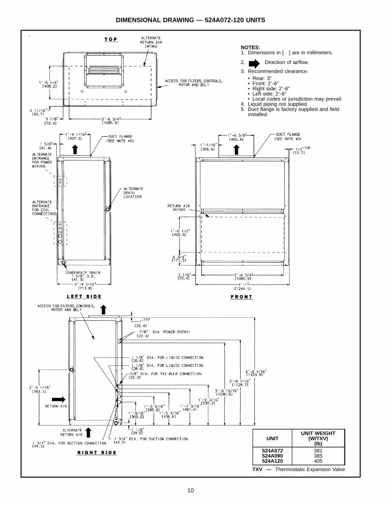
DIMENSIONAL DRAWING — 524A072-120 UNITS
NOTES:1. Dimensions in [ ] are in millimeters.
2. Direction of airflow.
3. Recommended clearance:• Rear: 39• Front: 28-69• Right side: 28-69• Left side: 28-69• Local codes or jurisdiction may prevail.
4. Liquid piping not supplied.5. Duct flange is factory supplied and field
installed.
UNITUNIT WEIGHT
(W/TXV)(lb)
524A072 381524A090 385524A120 405
TXV — Thermostatic Expansion Valve
10

DIMENSIONAL DRAWING — 524A150-240 UNITS
NOTES:1. Dimensions in [ ] are in millimeters.
2. Direction of airflow.
3. Recommended clearance:• Rear: 39• Front: 28-69• Right side: 28-69• Left side: 28-69• Local codes or jurisdiction may prevail.
4. Liquid piping not supplied.5. Duct flange is factory supplied and field
installed.
UNITUNIT WEIGHT
(W/TXV)(lb)
524A150 670524A180 685524A240 690
TXV — Thermostatic Expansion Valve
11
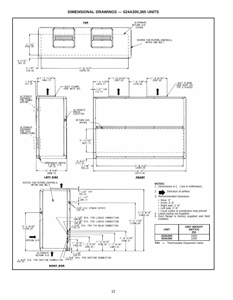
DIMENSIONAL DRAWINGS — 524A300,360 UNITS
NOTES:1. Dimensions in [ ] are in millimeters.
2. Direction of airflow.
3. Recommended clearance:• Rear: 39• Front: 28-69• Right side: 28-69• Left side: 28-69• Local codes or jurisdiction may prevail.
4. Liquid piping not supplied.5. Duct flange is factory supplied and field
installed.
UNITUNIT WEIGHT
(W/TXV)(lb)
524A300 1020524A360 1030
TXV — Thermostatic Expansion Valve
12

SPECIFICATIONS569C, 576B090-120 UNITS
BASE UNIT 569C072 569C090 569C120 576B090 576B102 576B120NOMINAL CAPACITY (tons) 6 71⁄2 10 71⁄2 81⁄2 10OPERATING WEIGHT (lb) 340 370 395 510 564 564RIGGING WEIGHT (lb) 390 420 445 560 614 614REFRIGERANT* R-22Operating Charge, Approx. (lb) 10.0
UNIT VOLUME (cu ft) 35.5 44.0 44.0 44.0 44.0 44.0COMPRESSOR Reciprocating, Hermetic Reciprocating, Semi-HermeticQty...Type 1...SF5572E 1...SF5594E 1...SF5612E/F 1...06DA818 1...06DA824 1...06DH824 (See Note)Qty Cylinders (ea) 4 4 4 4 6 6Speed (rpm) 3450 3450 3450 1750 1750 1750Oil Charge (oz) (ea) 65 65 65 88 128 128
CONDENSER AIR FAN Propeller; Direct DriveQty...Rpm 1...850 1...1100 1...1100 1...1100 1...1100 1...1100Diameter (in.) 26 26 26 26 26 26Motor Hp (NEMA) 1⁄3 3⁄4 3⁄4 3⁄4 3⁄4 3⁄4Watts 444 976 960 930 930 930Nominal Cfm Total 3800 6500 7000 6500 6500 6500
CONDENSER COIL Enhanced Copper Tubes, Aluminum Lanced FinsFace Area (sq ft) 12.24 18.0 20.50 18.0 18.0 18.0Storage Capacity (lb)† 11.26 16.56 18.87 16.56 16.56 16.56
CONNECTIONS (sweat)Suction (in.) 11⁄8 11⁄8 11⁄8 11⁄8 11⁄8 11⁄8Liquid (in.) 1⁄2 1⁄2 5⁄8 1⁄2 5⁄8 5⁄8
CONTROLSPressurestat Settings (psig)High Cutout 426 ± 7
Cut-in 320 ± 20Low Cutout 7 ± 3
Cut-in 22 ± 5
LEGENDNEMA — National Electrical Manufacturers Association*Unit is factory supplied with holding charge only.†Storage capacity of condenser coil with coil 80% full of liquid R-22at 124 F.
NOTE: Unit 576B120 has one step of unloading. Full load is 100% of capacity, andone step of unloading is 67% capacity. Unit 576B120 has the following unloadersettings: Load is 70 ± 1 psig and unload is 60 ± 2 psig.
566D UNITS
BASE UNIT 566D 120 150 180 240OPERATING WEIGHT (lb) 732 779 789 900REFRIGERANT* R-22Operating Charge, Approx. (lb) 22 23 23 28
COMPRESSOR Reciprocating, Semi-HermeticSpeed (Rpm) 1750No. Cylinders 6 6 6 4Model No. 06DD824 06DD328 06DD537 06E4250Oil (pt) 10 10 10 15.5Crankcase Heater Watts 125 125 125 180Unloader Setting (psig)Load 70 70 70 72Unload 60 60 60 62
OUTDOOR-AIR FANS Axial Flow, Direct DriveNo. ...Rpm 2...1075Diameter (in.) 26Motor Hp 1⁄2Nominal Total Airflow (Cfm) 11,000
FAN CYCLING CONTROLOperating Pressure (psig), No. 2 FanClose 260 ± 15Open 126 ± 10
OUTDOOR COILFace Area (sq ft) 29.2Storage Capacity (lb)† 27.2 40.0 40.0 40.0
CONTROLSPressurestat Settings (psig)High Cutout 395 ± 10
Cut-in 295 ± 10Low Cutout 27 ± 3
Cut-in 44 ± 5FUSIBLE PLUG (F) 200 200 200 210PIPING CONNECTIONS (in. ODM)Suction 11⁄8 13⁄8 13⁄8 15⁄8Liquid 5⁄8Hot Gas Bypass 3⁄8
*Unit is factory supplied with holding charge only.†Storage capacity is measured at liquid saturated temperatures of 125 F for 566D120,123 F for 566D150, and 130 F for 566D180,240 (coil 80% full of R-22 liquid).
13

SPECIFICATIONS (cont)576B300,360 UNITS
BASE UNIT 576B 300 360NOMINAL CAPACITY (tons) 25 30OPERATING WEIGHT (lb)Unit 1650 1803
COMPRESSOR Serviceable, Semi-HermeticQuantity...Type 1...06E9265 1...06E9275No. Cylinders — Speed (Rpm) 6 — 1750 6 — 1750Capacity Steps, No. 3 3
% 100-66-33 100-66-33Oil (pt) 20.0 20.0Oil Pressure Switch (psid)Set Point 9Differential 2.8
Crankcase Heater (watts) 180Capacity Control Suction Pressure Unloader(s)No. 1 Unloader Settings (psig)Load 76 76Unload 58 58
No. 2 Unloader Settings (psig)Load 78 78Unload 60 60
REFRIGERANT R-22Operating Charge (lb-oz) Approx.* 30-8 43-8
CONDENSER FANS Direct Drive PropellerQuantity...Diameter (in.) 2...30 2...30Nominal Airflow (cfm) 15,700 15,700Motor Hp...Rpm 1...1140 1...1140Power Consumption (watts ea.) 1490 1750
CONDENSER COIL Enhanced Copper Tube, Lanced Aluminum FinsRows...Fins/in. 2...19 3...17Total Face Area (sq ft) 39.2 39.2Storage 37.7 56.6
HIGH-PRESSURE SWITCH (psig)Cutout 426 ± 7Reset 320 ± 20
LOW-PRESSURE SWITCH (psig)Cutout 27 ± 3Reset 44 ± 5
FAN CYCLE SWITCH (psig)Close 260 ± 15Open 160 ± 10
OIL PRESSURE SWITCH (psig)Cut-in 14Cutout 6
CONNECTION SIZE (in.)Suction 15⁄8 21⁄8Liquid 7⁄8 7⁄8
Psid — Pounds per sq. in. Differential
*Unit is factory supplied with holding charge only.†Storage at 125 F liquid temperature and 80% full.
14
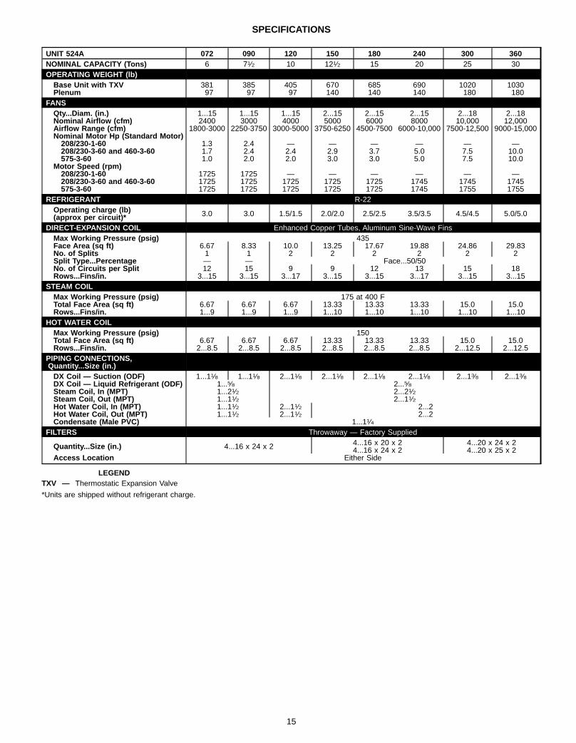
SPECIFICATIONS
UNIT 524A 072 090 120 150 180 240 300 360NOMINAL CAPACITY (Tons) 6 71⁄2 10 121⁄2 15 20 25 30OPERATING WEIGHT (lb)Base Unit with TXV 381 385 405 670 685 690 1020 1030Plenum 97 97 97 140 140 140 180 180
FANSQty...Diam. (in.) 1...15 1...15 1...15 2...15 2...15 2...15 2...18 2...18Nominal Airflow (cfm) 2400 3000 4000 5000 6000 8000 10,000 12,000Airflow Range (cfm) 1800-3000 2250-3750 3000-5000 3750-6250 4500-7500 6000-10,000 7500-12,500 9000-15,000Nominal Motor Hp (Standard Motor)208/230-1-60 1.3 2.4 — — — — — —208/230-3-60 and 460-3-60 1.7 2.4 2.4 2.9 3.7 5.0 7.5 10.0575-3-60 1.0 2.0 2.0 3.0 3.0 5.0 7.5 10.0
Motor Speed (rpm)208/230-1-60 1725 1725 — — — — — —208/230-3-60 and 460-3-60 1725 1725 1725 1725 1725 1745 1745 1745575-3-60 1725 1725 1725 1725 1725 1745 1755 1755
REFRIGERANT R-22Operating charge (lb)(approx per circuit)* 3.0 3.0 1.5/1.5 2.0/2.0 2.5/2.5 3.5/3.5 4.5/4.5 5.0/5.0
DIRECT-EXPANSION COIL Enhanced Copper Tubes, Aluminum Sine-Wave FinsMax Working Pressure (psig) 435Face Area (sq ft) 6.67 8.33 10.0 13.25 17.67 19.88 24.86 29.83No. of Splits 1 1 2 2 2 2 2 2Split Type...Percentage — — Face...50/50No. of Circuits per Split 12 15 9 9 12 13 15 18Rows...Fins/in. 3...15 3...15 3...17 3...15 3...15 3...17 3...15 3...15
STEAM COILMax Working Pressure (psig) 175 at 400 FTotal Face Area (sq ft) 6.67 6.67 6.67 13.33 13.33 13.33 15.0 15.0Rows...Fins/in. 1...9 1...9 1...9 1...10 1...10 1...10 1...10 1...10
HOT WATER COILMax Working Pressure (psig) 150Total Face Area (sq ft) 6.67 6.67 6.67 13.33 13.33 13.33 15.0 15.0Rows...Fins/in. 2...8.5 2...8.5 2...8.5 2...8.5 2...8.5 2...8.5 2...12.5 2...12.5
PIPING CONNECTIONS,Quantity...Size (in.)DX Coil — Suction (ODF) 1...11⁄8 1...11⁄8 2...11⁄8 2...11⁄8 2...11⁄8 2...11⁄8 2...13⁄8 2...13⁄8DX Coil — Liquid Refrigerant (ODF) 1...5⁄8 2...5⁄8Steam Coil, In (MPT) 1...21⁄2 2...21⁄2Steam Coil, Out (MPT) 1...11⁄2 2...11⁄2Hot Water Coil, In (MPT) 1...11⁄2 2...11⁄2 2...2Hot Water Coil, Out (MPT) 1...11⁄2 2...11⁄2 2...2Condensate (Male PVC) 1...11⁄4
FILTERS Throwaway — Factory Supplied
Quantity...Size (in.) 4...16 x 24 x 2 4...16 x 20 x 24...16 x 24 x 2
4...20 x 24 x 24...20 x 25 x 2
Access Location Either Side
LEGENDTXV — Thermostatic Expansion Valve
*Units are shipped without refrigerant charge.
15

SELECTION PROCEDURE
I DETERMINE COOLING LOAD, EVAPORATOR-AIRTEMPERATURE AND QUANTITY.Given:Total Cooling CapacityRequired (TC) . . . . . . . . . . . . . . . . . . . . . 230,000 Btuh
Sensible Heat CapacityRequired (SHC) . . . . . . . . . . . . . . . . . . . . 185,000 Btuh
Temperature Air Entering Condenser (Edb) . . . . . . . 95 FTemperature Air EnteringEvaporator (db/wb) . . . . . . . . . . . . . . 80 F db, 67 F wb
Evaporator Air Quantity . . . . . . . . . . . . . . . . . . 8,000 cfmExternal Static Pressure . . . . . . . . . . . . . . . . . 0.80 in. wgLength of InterconnectingRefrigerant Piping . . . . . . . . . . . . . . . . . . . 30 ft (Linear)
II SELECT CONDENSING UNIT AIR-HANDLERCOMBINATION.For this example, select a 566D240 unit matched with a524A240 unit (See Combination Ratings table, page 22.)This 566D240/524A240 condensing unit-air handler com-bination provides 235,600 Btuh of total cooling capacityand 187,900 Btuh of sensible capacity at the given condi-tions. If other temperatures or cfm values are required, in-terpolate the values from the combination ratings.
III DETERMINE SIZES OF LIQUID AND SUCTION LINES.Enter Refrigerant Piping Sizes table (page 46). The sizesshown are based on an equivalent length of pipe. Thisequivalent length is equal to the linear length of pipe indi-cated at the top of each sizing column, plus a 50% allow-ance for fitting losses. (For a more accurate determinationof actual equivalent length in place of using the estimated50% value, refer to the System Design Manual.) For thisexample, note in the linear length column that the properpipe size is 7⁄8 in. for the liquid line and 15⁄8 in. for the suc-tion line.
IV DETERMINE FAN RPM AND BHP (BRAKEHORSEPOWER).At the Air Delivery table (page 26), enter the 523A240 sec-tion at 8000 cfm and move to the External Static Pressure(ESP) column. Note that the conditions require 904 rpm at3.86 bhp. Use the standard motor and medium-static drive(option code HC or FD).
16

CONDENSING UNIT RATINGS — 569C UNITS
UNIT569C
SST(F)
CONDENSER AIR TEMPERATURE (F)80 85 95 100 105 115
Cap. SDT(F)
CompkW Cap. SDT
(F)CompkW Cap. SDT
(F)CompkW Cap. SDT
(F)CompkW Cap. SDT
(F)CompkW Cap. SDT
(F)CompkW
072(6 Tons)
25 52.3 104 4.87 50.3 109 5.04 46.1 118 5.38 43.9 123 5.51 41.6 127 5.65 37.4 137 5.9330 60.2 107 5.08 58.0 111 5.27 53.6 121 5.63 51.2 125 5.79 48.8 130 5.94 44.3 140 6.2535 68.2 110 5.29 65.8 114 5.49 61.0 123 5.88 58.5 128 6.06 56.1 132 6.23 51.2 142 6.5740 76.1 112 5.50 73.5 117 5.72 68.5 126 6.14 65.9 130 6.33 63.3 135 6.52 58.1 144 6.9045 84.0 115 5.72 81.3 119 5.94 75.9 128 6.39 73.2 133 6.60 70.5 137 6.82 65.0 146 7.2250 91.9 118 5.93 89.1 122 6.17 83.4 131 6.65 80.5 135 6.88 77.7 139 7.11 71.9 148 7.54
090(71⁄2 Tons)
25 69.1 102 6.31 66.7 107 6.53 61.6 116 6.91 59.1 120 7.10 56.7 125 7.27 51.9 134 7.5830 78.6 104 6.55 76.0 109 6.79 70.5 118 7.22 67.8 123 7.43 65.1 127 7.62 59.9 137 7.9835 88.1 107 6.78 85.2 111 7.04 79.3 120 7.52 76.5 125 7.76 73.6 129 7.98 67.9 139 8.3940 97.6 109 7.01 94.5 114 7.29 88.2 123 7.83 85.1 127 8.09 82.0 132 8.33 75.8 141 8.7945 107 111 7.24 104 116 7.55 97.1 125 8.14 93.8 129 8.42 90.5 134 8.69 83.8 143 9.1950 117 114 7.47 114 118 7.80 106 127 8.44 103 132 8.75 99.3 136 9.04 92.3 145 9.60
120(10 Tons)
25 92.6 106 8.88 89.2 110 9.19 81.8 119 9.73 78.5 124 10.0 75.1 128 10.3 68.1 138 10.730 105 108 9.29 102 113 9.62 93.7 122 10.2 90.1 126 10.5 86.3 131 10.8 78.8 140 11.335 118 111 9.70 114 116 10.1 106 124 10.7 102 129 11.0 97.6 133 11.4 89.6 142 11.940 131 114 10.1 126 118 10.5 118 127 11.2 113 131 11.6 109 136 11.9 100 145 12.545 143 117 10.5 139 121 10.9 129 130 11.7 125 134 12.1 120 138 12.4 111 147 13.250 157 120 11.0 152 124 11.4 142 132 12.2 137 137 12.6 132 141 13.0 122 150 13.8
LEGENDCap. — Capacity (1000 Btuh)kW — Compressor Motor Power InputSDT — Saturated Discharge TemperatureSST — Saturated Suction Temperature
CONDENSING UNIT RATINGS — 576B090-120 UNITS
UNIT576B
SST(F)
CONDENSER AIR TEMPERATURE (F)80 85 95 100 105 115
Cap. SDT(F)
CompkW Cap. SDT
(F)CompkW Cap. SDT
(F)CompkW Cap. SDT
(F)CompkW Cap. SDT
(F)CompkW Cap. SDT
(F)CompkW
090(71⁄2 Tons)
25 68.8 102 5.69 66.2 106 5.89 61.2 116 6.24 58.6 120 6.41 56.1 125 6.55 50.9 134 6.7930 78.4 104 5.92 75.6 108 6.14 70.1 118 6.55 67.4 122 6.74 64.6 127 6.91 59.0 136 7.2035 87.9 106 6.15 85.0 111 6.40 79.1 120 6.86 76.1 124 7.07 73.1 129 7.27 67.2 138 7.6240 97.5 109 6.38 94.3 113 6.65 88.0 122 7.17 84.8 127 7.41 81.7 131 7.63 75.3 140 8.0445 107.0 111 6.61 104.0 115 6.91 97.0 124 7.48 93.6 129 7.74 90.2 133 7.99 83.4 142 8.4650 117.0 114 6.83 113.0 118 7.16 106.0 127 7.78 103.0 131 8.08 99.2 136 8.36 92.0 144 8.88
102(81⁄2 Tons)
25 82.9 106 7.52 79.7 111 7.75 73.2 119 8.16 70.1 124 8.35 66.9 128 8.51 60.3 137 8.7830 94.1 109 7.94 90.7 114 8.20 83.7 122 8.66 80.4 127 8.88 76.8 131 9.07 69.7 140 9.4035 105.3 112 8.36 101.4 116 8.64 94.1 125 9.16 90.5 129 9.41 86.7 134 9.63 79.2 142 10.040 116.9 115 8.78 113.0 119 9.09 104.3 128 9.66 100.5 132 9.93 96.6 136 10.2 88.7 145 10.645 127.5 118 9.20 123.6 122 9.53 115.0 131 10.2 111.1 135 10.5 106.3 139 10.7 98.5 147 11.350 139.1 121 9.62 135.2 125 9.99 125.6 134 10.7 121.7 138 11.0 116.9 142 11.3 108.2 150 11.9
120(10 Tons)
25 84.4 106 7.51 81.1 110 7.74 74.4 119 8.15 71.3 124 8.34 68.0 128 8.50 61.4 137 8.7830 95.8 109 7.92 92.3 113 8.17 85.1 122 8.64 81.7 126 8.86 78.1 131 9.05 71.1 139 9.4035 107.0 112 8.33 103.0 116 8.61 95.8 125 9.14 92.1 129 9.38 88.3 133 9.61 80.7 142 10.040 119.0 115 8.74 115.0 119 9.05 107.0 127 9.63 102.0 132 9.91 93.4 136 10.2 90.3 145 10.645 130.0 118 9.15 126.0 122 9.49 117.0 130 10.1 113.0 134 10.4 109.0 139 10.7 100.0 147 11.250 142.0 121 9.57 138.0 125 9.94 128.0 133 10.6 124.0 137 11.0 119.0 141 11.3 110.0 150 11.9
LEGENDCap. — Capacity (1000 Btuh)kW — Compressor Motor Power InputSDT — Saturated Discharge TemperatureSST — Saturated Suction Temperature
17

CONDENSING UNIT RATINGS — 566D UNITS
UNIT566D
SST(F)
CONDENSER AIR TEMPERATURE (F)85 95 100 105 115
Cap. SDT(F)
CompkW Cap. SDT
(F)CompkW Cap. SDT
(F)CompkW Cap. SDT
(F)CompkW Cap. SDT
(F)CompkW
120(10 Tons)
25 86 109 7.5 79 118 8.0 75 123 8.2 72 127 8.4 66 137 8.830 96 111 7.9 88 120 8.4 85 124 8.7 81 129 8.9 74 138 9.335 106 113 8.3 98 122 8.8 94 126 9.1 91 131 9.4 83 140 9.840 117 115 8.6 109 124 9.3 105 128 9.6 101 133 9.8 93 142 10.445 129 117 9.0 120 126 9.7 116 131 10.0 111 135 10.3 103 144 10.950 141 120 9.4 132 129 10.1 127 133 10.5 122 137 10.8 113 146 11.5
150(121⁄2 Tons)
25 104 109 9.1 97 119 9.7 93 124 10.0 89 129 10.2 82 139 10.730 117 109 9.4 109 119 10.0 105 124 10.4 101 129 10.7 93 139 11.335 131 110 9.7 122 120 10.4 118 124 10.7 113 129 11.1 104 139 11.840 145 112 10.0 135 121 10.8 131 126 11.2 126 130 11.5 117 140 12.345 159 114 10.4 149 123 11.2 144 127 11.6 139 132 12.0 130 141 12.850 174 116 10.7 164 125 11.6 159 129 12.1 153 134 12.5 143 143 13.3
180(15 Tons)
25 140 110 13.1 131 119 13.9 127 124 14.3 122 128 14.7 114 138 15.330 155 112 13.7 145 121 14.6 140 126 15.1 136 130 15.5 126 139 16.235 170 114 14.4 160 123 15.4 155 128 15.8 150 132 16.3 140 141 17.140 187 117 15.1 176 126 16.1 170 130 16.6 165 135 17.1 154 144 18.145 204 119 15.7 192 128 16.9 186 133 17.5 180 137 18.0 168 146 19.050 222 122 16.4 209 131 17.7 203 135 18.3 197 140 18.9 184 148 20.0
240(20 Tons)
25 172 111 16.4 157 119 17.1 149 123 17.4 142 128 17.7 128 136 18.130 195 114 17.6 180 123 18.4 172 127 18.8 164 131 19.1 149 140 19.635 219 118 18.7 203 126 19.7 194 130 20.1 186 134 20.5 170 143 21.140 243 121 19.9 225 129 21.0 217 133 21.5 208 137 21.9 191 146 22.745 266 125 21.1 248 133 22.3 239 137 22.8 230 141 23.3 212 149 24.250 290 128 22.2 271 136 23.5 262 140 24.1 252 144 24.7 232 152 25.7
LEGENDCap. — Capacity (1000 Btuh)kW — Compressor Motor Power InputSDT — Saturated Discharge TemperatureSST — Saturated Suction Temperature
CONDENSING UNIT RATINGS — 576B300,360 UNITS
UNIT576B
SST(F)
CONDENSER AIR TEMPERATURE (F)85 95 100 105 115
Cap. SDT(F)
CompkW Cap. SDT
(F)CompkW Cap. SDT
(F)CompkW Cap. SDT
(F)CompkW Cap. SDT
(F)CompkW
300(25 Tons)
20 199 108 20.7 183 117 21.6 176 121 22.0 169 126 22.4 154 135 23.025 230 111 22.2 213 120 23.2 204 124 23.7 196 129 24.1 180 138 24.930 261 114 23.6 242 123 24.8 233 127 25.4 224 131 25.9 206 140 26.835 292 117 25.0 271 125 26.4 261 130 27.0 252 134 27.6 232 143 28.740 323 120 26.4 301 128 28.0 290 133 28.7 279 137 29.3 258 145 30.645 354 123 27.8 330 131 29.5 319 135 30.3 307 140 31.1 284 148 32.450 386 126 29.3 361 134 31.2 348 138 32.0 336 142 32.9 312 151 34.4
360(30 Tons)
20 227 107 23.5 209 116 24.4 201 121 24.8 193 125 25.1 176 134 25.625 260 110 25.1 241 119 26.2 232 124 26.6 223 128 27.0 205 137 27.730 293 113 26.6 273 122 27.9 264 126 28.4 254 131 28.9 234 140 29.835 326 116 28.1 305 125 29.6 295 129 30.2 284 133 30.8 263 142 31.940 359 119 29.6 337 128 31.3 326 132 32.1 314 136 32.8 292 145 34.045 393 122 31.1 369 130 33.0 357 135 33.9 345 139 34.7 321 147 36.150 428 125 32.7 402 133 34.8 390 138 35.7 377 142 36.6 351 150 38.2
LEGENDCap. — Capacity (1000 Btuh)kW — Compressor Motor Power InputSDT — Saturated Discharge TemperatureSST — Saturated Suction Temperature
18

COMBINATION RATINGS — 569C UNITS
569C072/524A072
Temp (F)Air EnteringCondenser
(Edb)
Evaporator Air — Cfm/BF1800/0.06 2400/0.10 3000/0.12
Evaporator Air — Ewb (F)72 67 62 72 67 62 72 67 62
85TC 78.8 72.7 66.1 82.4 76.4 70.0 84.6 79.1 73.1SHC 39.9 49.5 62.4 44.4 58.1 70.0 50.2 64.6 73.1kW 5.87 5.70 5.51 5.97 5.80 5.62 6.03 5.88 5.71
95TC 75.3 69.5 63.3 78.7 72.9 67.1 80.6 75.4 70.1SHC 38.4 48.3 60.2 43.0 56.8 67.1 48.9 63.3 70.1kW 6.37 6.17 5.97 6.48 6.29 6.09 6.55 6.37 6.19
100TC 73.6 67.8 61.8 76.8 71.1 65.6 78.6 73.6 68.5SHC 37.7 47.6 58.9 42.3 56.0 65.6 48.2 62.6 68.5kW 6.61 6.40 6.18 6.73 6.52 6.32 6.80 6.61 6.43
105TC 71.8 66.2 60.3 74.9 69.3 64.0 76.7 71.7 66.9SHC 36.9 47.0 57.7 41.6 55.3 64.0 47.6 61.9 66.9kW 6.87 6.64 6.39 7.00 6.77 6.55 7.08 6.87 6.67
115TC 68.1 62.7 57.2 70.9 65.6 60.8 72.5 67.8 63.7SHC 35.3 45.6 55.1 40.1 53.8 60.8 46.2 60.4 63.6kW 7.36 7.11 6.86 7.50 7.25 7.02 7.57 7.35 7.16
569C072/524A090
Temp (F)Air EnteringCondenser
(Edb)
Evaporator Air — Cfm/BF2250/0.06 3000/0.10 3750/0.12
Evaporator Air — Ewb (F)72 67 62 72 67 62 72 67 62
85TC 85.1 78.5 72.0 87.6 82.0 76.4 89.7 84.6 79.7SHC 44.3 57.1 69.9 52.2 66.1 76.4 57.0 74.8 79.7kW 6.05 5.86 5.68 6.12 5.96 5.80 6.18 6.03 5.89
95TC 81.2 74.9 68.8 83.4 78.1 73.0 85.3 80.5 76.2SHC 42.7 55.5 67.1 50.8 64.4 73.0 55.5 73.2 76.2kW 6.57 6.36 6.15 6.64 6.46 6.29 6.71 6.55 6.40
100TC 79.2 73.1 67.1 81.3 76.1 71.3 83.2 78.5 74.5SHC 41.9 54.7 65.6 50.1 63.6 71.3 54.7 72.4 74.4kW 6.82 6.59 6.37 6.90 6.71 6.53 6.97 6.80 6.65
105TC 77.3 71.2 65.4 79.2 74.1 69.5 81.0 76.5 72.7SHC 41.1 53.9 64.2 49.4 62.7 69.5 54.0 71.6 72.7kW 7.10 6.85 6.61 7.18 6.97 6.78 7.26 7.07 6.91
115TC 73.2 67.3 61.8 74.8 70.0 65.8 76.4 72.2 68.9SHC 39.4 52.2 61.1 47.9 61.0 65.8 52.4 69.9 68.9kW 7.60 7.33 7.07 7.68 7.45 7.26 7.75 7.55 7.40
569C090/524A072
Temp (F)Air EnteringCondenser
(Edb)
Evaporator Air — Cfm/BF1800/0.06 2400/0.10 3000/0.12
Evaporator Air — Ewb (F)72 67 62 72 67 62 72 67 62
85TC 92.0 84.7 — 96.8 89.6 80.9 99.9 93.0 84.3SHC 45.6 54.1 — 49.8 63.4 80.9 55.3 69.9 84.3kW 7.22 7.02 — 7.35 7.16 6.92 7.44 7.25 7.01
95TC 88.2 81.3 73.7 92.7 85.8 77.9 95.4 89.0 81.2SHC 43.9 52.8 68.6 48.3 61.9 77.8 53.8 68.4 81.2kW 7.83 7.59 7.32 7.99 7.75 7.47 8.08 7.86 7.59
100TC 86.3 79.6 72.1 90.6 83.9 76.3 93.2 87.0 79.5SHC 43.1 52.1 67.4 47.5 61.2 76.2 53.1 67.6 79.5kW 8.14 7.88 7.60 8.30 8.04 7.75 8.40 8.16 7.88
105TC 84.4 77.8 70.5 88.5 81.9 74.6 91.0 84.9 77.9SHC 42.3 51.4 66.1 46.7 60.4 74.6 52.3 66.8 77.9kW 8.43 8.15 7.84 8.61 8.33 8.02 8.71 8.45 8.15
115TC 80.3 74.1 67.3 84.1 77.9 71.3 86.3 80.7 74.4SHC 40.6 50.0 63.4 45.0 58.8 71.3 50.8 65.3 74.4kW 9.02 8.70 8.37 9.21 8.89 8.56 9.32 9.03 8.72
LEGENDBF — Bypass FactorEdb — Entering Dry BulbEER — Energy Efficiency RatioEwb — Entering Wet BulbkW — Compressor Motor Power InputSHC — Sensible Heat Capacity (1000 Btuh), GrossTC — Total Capacity (1000 Btuh), Gross— — Unit cannot operate at these conditions due to interruption by safety
control.
NOTES:1. Gross capacities shown do not include a deduction for evaporator fan motor
heat.2. Combination ratings are based on a 2° F line loss. For a close-coupled system
(less than 15 ft), add 2% to ratings. All combination ratings are based on R-22.
569C090/524A090
Temp (F)Air EnteringCondenser
(Edb)
Evaporator Air — Cfm/BF2250/0.06 3000/0.10 3750/0.12
Evaporator Air — Ewb (F)72 67 62 72 67 62 72 67 62
85TC 100.1 92.4 84.3 104.2 97.3 89.3 107.1 100.5 93.0SHC 50.5 63.2 80.4 57.7 72.5 89.3 63.1 81.2 93.0kW 7.44 7.23 7.01 7.56 7.37 7.15 7.63 7.45 7.25
95TC 95.8 88.4 80.9 99.4 92.8 85.6 102.0 95.9 89.2SHC 48.7 61.4 77.5 56.1 70.6 85.6 61.3 79.3 89.2kW 8.09 7.84 7.57 8.22 7.99 7.74 8.31 8.10 7.87
100TC 93.6 86.4 79.1 97.0 90.6 83.7 99.5 93.6 87.3SHC 47.8 60.5 75.9 55.3 69.7 83.7 60.4 78.4 87.3kW 8.41 8.14 7.86 8.54 8.30 8.04 8.64 8.41 8.17
105TC 91.4 84.3 77.2 94.6 88.4 81.8 97.0 91.3 85.3SHC 46.9 59.6 74.3 54.5 68.8 81.8 59.6 77.5 85.3kW 8.73 8.43 8.13 8.86 8.60 8.32 8.96 8.72 8.47
115TC 86.8 80.1 73.5 89.6 83.8 77.9 91.7 86.5 81.3SHC 45.0 57.8 71.1 52.9 66.8 77.9 57.7 75.6 81.3kW 9.34 9.01 8.67 9.48 9.19 8.89 9.59 9.32 9.06
569C090/524A120
Temp (F)Air EnteringCondenser
(Edb)
Evaporator Air — Cfm/BF3000/0.05 4000/0.07 5000/0.12
Evaporator Air — Ewb (F)72 67 62 72 67 62 72 67 62
85TC 110.2 102.0 94.2 114.0 106.3 99.8 116.1 108.9 104.3SHC 58.1 76.0 91.5 66.0 87.2 99.7 74.8 99.6 104.3kW 7.72 7.50 7.28 7.82 7.61 7.43 7.88 7.68 7.56
95TC 105.0 97.2 90.0 108.3 101.2 95.3 110.2 103.5 99.8SHC 55.9 74.0 88.0 63.8 84.8 95.3 72.7 97.4 99.8kW 8.41 8.14 7.89 8.53 8.28 8.08 8.60 8.36 8.23
100TC 102.5 94.9 87.9 105.7 98.7 93.1 107.5 100.9 97.6SHC 54.9 73.0 86.3 62.8 83.7 93.1 71.8 96.3 97.6kW 8.75 8.46 8.20 8.87 8.61 8.39 8.94 8.69 8.56
105TC 100.0 92.5 85.8 103.0 96.2 90.9 — 98.2 95.3SHC 53.9 71.9 84.5 61.8 82.5 90.9 — 95.2 95.3kW 9.09 8.78 8.49 9.22 8.93 8.71 — 9.02 8.89
115TC 94.6 87.6 81.3 97.3 90.9 86.2 — 92.7 90.6SHC 51.7 69.8 80.8 59.6 80.1 86.2 — 93.0 90.6kW 9.73 9.38 9.07 9.86 9.55 9.31 — 9.63 9.53
569C120/524A120
Temp (F)Air EnteringCondenser
(Edb)
Evaporator Air — Cfm/BF3000/0.05 4000/0.07 5000/0.12
Evaporator Air — Ewb (F)72 67 62 72 67 62 72 67 62
85TC 133.6 123.2 112.5 139.7 129.6 119.2 143.4 133.7 124.2SHC 67.7 85.1 106.7 75.9 97.9 119.2 84.2 109.7 124.2kW 10.73 10.41 10.08 10.92 10.61 10.29 11.03 10.74 10.45
95TC 127.5 118.2 108.8 132.6 123.7 114.9 135.6 127.2 119.6SHC 65.2 82.9 103.7 73.2 95.2 114.8 81.5 107.0 119.5kW 11.63 11.21 10.78 11.86 11.46 11.06 12.00 11.62 11.27
100TC 124.8 115.0 105.3 130.1 120.7 111.7 133.2 124.3 116.7SHC 64.1 81.6 100.7 72.2 93.8 111.7 80.7 105.9 116.7kW 12.09 11.68 11.28 12.31 11.92 11.54 12.44 12.07 11.75
105TC 121.5 112.3 103.2 126.3 117.6 109.3 129.1 120.8 114.1SHC 62.7 80.4 99.0 70.7 92.3 109.3 79.2 104.4 114.1kW 12.47 12.05 11.64 12.69 12.29 11.91 12.81 12.44 12.13
115TC 115.5 106.4 97.6 120.0 111.4 103.7 122.6 114.4 108.6SHC 60.2 77.9 94.3 68.3 89.5 103.7 77.0 101.8 108.6kW 13.49 12.91 12.35 13.77 13.22 12.73 13.94 13.42 13.05
3. SHC is based on 80 F edb temperature of air entering evaporator coil.Below 80 F edb, subtract (corr factor x cfm) from SHC.Above 80 F edb, add (corr factor x cfm) to SHC.
BYPASSFACTOR(BF)
ENTERING-AIR DRY BULB TEMP (F)79 78 77 76 75 under 7581 82 83 84 85 over 85
Correction Factor.05 1.04 2.07 3.11 4.14 5.18
Use formulashown below.
.10 .98 1.96 2.94 3.92 4.91
.20 .87 1.74 2.62 3.49 4.36
.30 .76 1.53 2.29 3.05 3.82
Interpolation is permissible.Correction Factor = 1.10 x (1 – BF) x (edb – 80).
19

COMBINATION RATINGS — 569C UNITS (cont)
569C120/524A150
Temp (F)Air EnteringCondenser
(Edb)
Evaporator Air — Cfm/BF3750/0.06 5000/0.08 6250/0.10
Evaporator Air — Ewb (F)72 67 62 72 67 62 72 67 62
85TC 141.9 130.2 120.2 147.2 136.2 127.6 150.9 140.1 133.5SHC 75.2 95.6 116.3 85.0 111.2 127.6 94.8 125.0 133.5kW 10.99 10.63 10.32 11.15 10.81 10.55 11.27 10.93 10.73
95TC 134.5 124.1 115.6 138.9 129.3 122.3 142.1 132.7 127.6SHC 72.4 92.8 112.4 81.9 108.3 122.3 91.8 121.5 127.6kW 11.95 11.48 11.09 12.15 11.71 11.39 12.29 11.87 11.64
100TC 132.2 121.1 112.4 136.7 126.5 119.4 140.0 130.1 125.0SHC 71.4 91.4 109.6 81.1 107.1 119.4 91.1 120.3 125.0kW 12.40 11.94 11.57 12.59 12.16 11.87 12.73 12.31 12.10
105TC 128.2 117.8 109.8 132.3 122.9 116.5 135.4 126.1 121.8SHC 69.9 89.9 107.4 79.5 105.5 116.5 89.5 118.4 121.8kW 12.77 12.30 11.94 12.96 12.53 12.24 13.10 12.68 12.48
115TC 121.9 111.5 104.0 125.8 116.4 110.7 — 119.5 116.0SHC 67.5 87.0 102.5 77.1 102.7 110.7 — 115.4 116.0kW 13.89 13.23 12.75 14.14 13.54 13.18 — 13.74 13.52
COMBINATION RATINGS — 569B090-120 UNITS
576B090/524A072
Temp (F)Air EnteringCondenser
(Edb)
Evaporator Air — Cfm/BF1800/0.06 2400/0.10 3000/0.12
Evaporator Air — Ewb (F)72 67 62 72 67 62 72 67 62
85TC 91.8 84.5 — 96.7 89.4 80.6 99.8 92.8 84.1SHC 45.5 54.0 — 49.8 63.4 80.6 55.3 69.8 84.1kW 6.57 6.37 — 6.71 6.50 6.26 6.79 6.60 6.36
95TC 88.1 81.2 73.5 92.6 85.7 77.7 95.4 88.9 81.0SHC 43.9 52.8 68.5 48.2 61.9 77.7 53.8 68.3 81.0kW 7.17 6.93 6.67 7.33 7.09 6.81 7.42 7.20 6.93
100TC 86.1 79.4 71.9 90.5 83.7 76.0 93.1 86.8 79.3SHC 43.1 52.1 67.1 47.4 61.1 76.0 53.0 67.5 79.3kW 7.46 7.21 6.92 7.62 7.37 7.08 7.72 7.48 7.20
105TC 84.2 77.6 70.4 88.3 81.8 74.4 90.8 84.7 77.7SHC 42.2 51.4 65.9 46.6 60.3 74.4 52.3 66.8 77.7kW 7.73 7.46 7.15 7.91 7.63 7.32 8.02 7.76 7.46
115TC 82.6 73.0 63.1 88.8 78.9 68.9 92.7 83.3 73.6SHC 41.5 49.6 60.0 46.8 59.1 68.9 52.9 66.2 73.6kW 8.21 7.99 7.76 8.35 8.12 7.89 8.44 8.23 8.00
576B090/524A090
Temp (F)Air EnteringCondenser
(Edb)
Evaporator Air — Cfm/BF2250/0.06 3000/0.10 3750/0.12
Evaporator Air — Ewb (F)72 67 62 72 67 62 72 67 62
85TC 100.1 92.2 84.1 104.2 97.2 89.1 107.1 100.4 92.9SHC 50.4 63.1 80.2 57.7 72.4 89.1 63.1 81.2 92.9kW 6.80 6.58 6.36 6.92 6.72 6.49 7.00 6.81 6.60
95TC 95.7 88.3 80.7 99.3 92.7 85.5 101.9 95.8 89.1SHC 48.6 61.4 77.3 56.1 70.6 85.5 61.3 79.3 89.1kW 7.44 7.18 6.92 7.56 7.33 7.08 7.65 7.44 7.21
100TC 93.5 86.2 78.8 96.9 90.5 83.5 99.4 93.4 87.1SHC 47.7 60.5 75.7 55.3 69.6 83.5 60.4 78.4 87.1kW 7.74 7.46 7.19 7.86 7.62 7.36 7.96 7.73 7.50
105TC 91.2 84.1 77.0 94.4 88.2 81.6 96.8 91.1 85.2SHC 46.8 59.6 74.2 54.5 68.7 81.6 59.5 77.4 85.2kW 8.03 7.73 7.43 8.17 7.91 7.63 8.27 8.03 7.78
115TC 93.3 82.4 71.9 98.6 88.7 78.8 102.7 93.3 84.1SHC 47.7 58.8 69.8 55.9 68.9 78.8 61.5 78.3 84.1kW 8.46 8.21 7.96 8.58 8.35 8.12 8.68 8.46 8.24
LEGENDBF — Bypass FactorEdb — Entering Dry BulbEER — Energy Efficiency RatioEwb — Entering Wet BulbkW — Compressor Motor Power InputSHC — Sensible Heat Capacity (1000 Btuh), GrossTC — Total Capacity (1000 Btuh), Gross— — Unit cannot operate at these conditions due to interruption by safety
control.
NOTES:1. Gross capacities shown do not include a deduction for evaporator fan motor
heat.2. Combination ratings are based on a 2° F line loss. For a close-coupled system
(less than 15 ft), add 2% to ratings. All combination ratings are based on R-22.
576B090/524A120
Temp (F)Air EnteringCondenser
(Edb)
Evaporator Air — Cfm/BF3000/0.05 4000/0.07 5000/0.12
Evaporator Air — Ewb (F)72 67 62 72 67 62 72 67 62
85TC 110.3 102.0 94.1 114.1 106.4 99.7 116.3 109.0 104.3SHC 58.1 76.0 91.4 66.0 87.2 99.7 74.8 99.6 104.3kW 7.08 6.85 6.63 7.19 6.98 6.79 7.25 7.05 6.92
95TC 105.0 97.2 89.9 108.4 101.2 95.2 110.3 103.4 99.8SHC 55.9 73.9 87.9 63.8 84.8 95.2 72.8 97.4 99.7kW 7.75 7.49 7.24 7.87 7.62 7.42 7.94 7.70 7.57
100TC 102.4 94.8 87.7 105.6 98.6 93.0 107.4 100.8 97.5SHC 54.9 72.9 86.1 62.8 83.6 93.0 71.8 96.3 97.5kW 8.07 7.78 7.52 8.19 7.93 7.72 8.26 8.01 7.89
105TC 99.7 92.3 85.6 102.7 96.0 90.7 — 98.0 95.1SHC 53.8 71.9 84.3 61.7 82.4 90.7 — 95.1 95.1kW 8.39 8.08 7.79 8.52 8.23 8.01 — 8.32 8.20
115TC 107.4 95.3 84.5 113.0 101.5 92.5 — 105.2 99.4SHC 56.9 73.1 83.4 65.6 85.0 92.5 — 98.1 99.4kW 8.79 8.50 8.25 8.91 8.65 8.44 — 8.73 8.60
576B102/524A090
Temp (F)Air EnteringCondenser
(Edb)
Evaporator Air — Cfm/BF2250/0.06 3000/0.10 3750/0.12
Evaporator Air — Ewb (F)72 67 62 72 67 62 72 67 62
85TC 111.9 103.3 — 117.3 109.3 99.5 120.7 113.0 103.5SHC 55.3 68.0 — 62.1 77.6 99.4 67.8 86.2 103.4kW 9.05 8.69 — 9.27 8.94 8.53 9.41 9.09 8.69
95TC 106.6 98.1 89.2 111.5 103.7 94.4 114.8 107.4 98.5SHC 53.1 65.6 84.6 60.2 75.2 94.4 65.8 83.9 98.5kW 9.78 9.34 8.90 10.02 9.63 9.16 10.19 9.81 9.37
100TC 104.3 95.9 87.2 109.0 101.4 92.4 112.2 104.9 96.4SHC 52.2 64.7 82.9 59.3 74.2 92.4 64.8 83.0 96.4kW 10.13 9.67 9.20 10.38 9.97 9.49 10.56 10.16 9.70
105TC 101.6 93.6 85.4 105.8 98.7 90.4 108.7 102.0 94.2SHC 51.1 63.7 81.4 58.3 73.1 90.4 63.6 81.8 94.2kW 10.46 10.05 9.62 10.67 10.31 9.88 10.83 10.48 10.08
115TC 96.6 88.7 80.7 100.5 93.5 85.8 103.3 96.7 89.6SHC 49.0 61.6 77.3 56.5 70.9 85.8 61.7 79.7 89.6kW 11.16 10.60 10.03 11.44 10.94 10.39 11.64 11.17 10.66
3. SHC is based on 80 F edb temperature of air entering evaporator coil.Below 80 F edb, subtract (corr factor x cfm) from SHC.Above 80 F edb, add (corr factor x cfm) to SHC.
BYPASSFACTOR(BF)
ENTERING-AIR DRY BULB TEMP (F)79 78 77 76 75 under 7581 82 83 84 85 over 85
Correction Factor.05 1.04 2.07 3.11 4.14 5.18
Use formulashown below.
.10 .98 1.96 2.94 3.92 4.91
.20 .87 1.74 2.62 3.49 4.36
.30 .76 1.53 2.29 3.05 3.82
Interpolation is permissible.Correction Factor = 1.10 x (1 – BF) x (edb – 80).
20

COMBINATION RATINGS — 569B090-120 UNITS (cont)
576B102/524A120
Temp (F)Air EnteringCondenser
(Edb)
Evaporator Air — Cfm/BF3000/0.05 4000/0.07 5000/0.12
Evaporator Air — Ewb (F)72 67 62 72 67 62 72 67 62
85TC 123.9 114.9 105.9 128.7 120.1 111.8 131.5 123.4 116.4SHC 63.7 81.5 101.2 71.6 93.5 111.8 80.1 105.5 116.4kW 9.54 9.17 8.79 9.74 9.39 9.04 9.86 9.52 9.23
95TC 118.1 109.1 100.4 122.6 114.2 106.3 125.3 117.2 111.1SHC 61.3 79.1 96.6 69.3 90.8 106.3 77.9 103.0 111.1kW 10.36 9.90 9.46 10.59 10.16 9.76 10.72 10.31 10.00
100TC 115.4 106.6 98.1 119.8 111.4 104.0 122.3 114.4 108.8SHC 60.2 78.0 94.7 68.2 89.5 103.9 76.9 101.8 108.7kW 10.73 10.26 9.79 10.97 10.52 10.11 11.11 10.68 10.37
105TC 111.9 103.5 95.6 115.8 108.0 101.2 118.0 110.6 105.8SHC 58.8 76.7 92.7 66.7 88.0 101.2 75.4 100.3 105.8kW 10.99 10.56 10.15 11.19 10.79 10.44 11.30 10.92 10.67
115TC 106.5 98.2 90.5 110.2 102.5 96.1 — 105.0 100.9SHC 56.6 74.4 88.4 64.5 85.4 96.1 — 98.0 100.9kW 11.87 11.28 10.73 12.13 11.58 11.13 — 11.76 11.47
576B120/524A090
Temp (F)Air EnteringCondenser
(Edb)
Evaporator Air — Cfm/BF2250/0.06 3000/0.10 3750/0.12
Evaporator Air — Ewb (F)72 67 62 72 67 62 72 67 62
85TC 113.1 104.3 — 118.7 110.5 100.3 122.3 114.3 104.4SHC 55.8 68.4 — 62.6 78.1 100.3 68.4 86.7 104.4kW 8.98 8.62 — 9.20 8.87 8.46 9.34 9.02 8.62
95TC 108.2 100.0 91.3 113.0 105.5 96.4 116.2 109.0 100.3SHC 53.8 66.5 86.4 60.7 76.0 96.4 66.3 84.6 100.3kW 9.69 9.30 8.89 9.91 9.56 9.13 10.06 9.73 9.31
100TC 105.2 96.6 87.6 110.1 102.3 93.0 113.5 105.9 97.1SHC 52.6 65.0 83.3 59.7 74.6 93.0 65.3 83.4 97.1kW 10.05 9.67 9.27 10.27 9.92 9.51 10.42 10.09 9.69
105TC 103.0 94.5 85.9 107.6 100.0 91.1 110.7 103.5 95.1SHC 51.6 64.1 81.8 58.9 73.6 91.1 64.3 82.4 95.1kW 10.41 10.02 9.61 10.63 10.27 9.86 10.78 10.44 10.05
115TC 97.5 89.7 81.7 101.5 94.5 86.7 104.3 97.7 90.5SHC 49.4 62.0 78.2 56.8 71.3 86.7 62.1 80.1 90.5kW 11.05 10.56 10.07 11.29 10.86 10.38 11.47 11.06 10.61
LEGENDBF — Bypass FactorEdb — Entering Dry BulbEER — Energy Efficiency RatioEwb — Entering Wet BulbkW — Compressor Motor Power InputSHC — Sensible Heat Capacity (1000 Btuh), GrossTC — Total Capacity (1000 Btuh), Gross— — Unit cannot operate at these conditions due to interruption by safety
control.
NOTES:1. Gross capacities shown do not include a deduction for evaporator fan motor
heat.2. Combination ratings are based on a 2° F line loss. For a close-coupled system
(less than 15 ft), add 2% to ratings. All combination ratings are based on R-22.
576B120/524A120
Temp (F)Air EnteringCondenser
(Edb)
Evaporator Air — Cfm/BF3000/0.05 4000/0.07 5000/0.12
Evaporator Air — Ewb (F)72 67 62 72 67 62 72 67 62
85TC 125.5 116.2 106.9 130.5 121.7 113.0 133.4 125.1 117.7SHC 64.3 82.1 102.1 72.4 94.2 113.0 80.7 106.2 117.7kW 9.47 9.10 8.73 9.67 9.32 8.97 9.79 9.45 9.16
95TC 119.3 110.7 102.3 123.7 115.6 108.0 126.3 118.6 112.5SHC 61.8 79.7 98.2 69.7 91.4 108.0 78.3 103.5 112.5kW 10.21 9.81 9.41 10.42 10.03 9.68 10.53 10.17 9.89
100TC 116.8 107.7 98.9 121.4 112.8 104.9 124.0 115.8 109.8SHC 60.8 78.4 95.4 68.8 90.1 104.9 77.5 102.4 109.8kW 10.57 10.16 9.77 10.77 10.39 10.04 10.89 10.53 10.26
105TC 114.0 105.2 96.7 118.3 110.0 102.6 120.8 112.9 107.4SHC 59.6 77.4 93.6 67.7 88.9 102.6 76.4 101.2 107.4kW 10.94 10.52 10.12 11.14 10.75 10.40 11.26 10.88 10.63
115TC 107.5 99.2 91.5 111.2 103.5 97.1 — 106.0 101.8SHC 57.0 74.8 89.2 64.9 85.9 97.1 — 98.4 101.8kW 11.66 11.15 10.67 11.89 11.42 11.02 — 11.57 11.31
576B120/524A150
Temp (F)Air EnteringCondenser
(Edb)
Evaporator Air — Cfm/BF3750/0.06 5000/0.08 6250/0.10
Evaporator Air — Ewb (F)72 67 62 72 67 62 72 67 62
85TC 132.4 122.0 113.7 136.7 127.2 120.4 139.8 130.5 125.6SHC 71.6 91.8 110.7 81.1 107.4 120.4 91.0 120.5 125.6kW 9.75 9.33 9.00 9.92 9.54 9.26 10.04 9.67 9.48
95TC 125.5 115.8 108.4 129.3 120.5 114.7 132.0 123.4 119.7SHC 68.9 89.0 106.3 78.4 104.5 114.7 88.3 117.2 119.7kW 10.50 10.04 9.70 10.68 10.26 9.99 10.81 10.40 10.22
100TC 123.3 112.9 105.3 127.2 117.8 112.0 130.2 121.0 117.3SHC 68.0 87.6 103.6 77.6 103.4 112.0 87.7 116.1 117.2kW 10.86 10.39 10.06 11.03 10.62 10.35 11.16 10.76 10.59
105TC 120.2 110.0 102.9 123.9 114.8 109.4 — 117.8 114.5SHC 66.8 86.3 101.5 76.4 102.1 109.4 — 114.6 114.5kW 11.23 10.75 10.41 11.40 10.97 10.72 — 11.12 10.96
115TC 113.0 103.4 97.2 — 107.8 103.3 — 110.4 108.2SHC 64.1 83.3 96.7 — 99.0 103.3 — 111.1 108.2kW 12.00 11.41 11.02 — 11.68 11.40 — 11.85 11.70
3. SHC is based on 80 F edb temperature of air entering evaporator coil.Below 80 F edb, subtract (corr factor x cfm) from SHC.Above 80 F edb, add (corr factor x cfm) to SHC.
BYPASSFACTOR(BF)
ENTERING-AIR DRY BULB TEMP (F)79 78 77 76 75 under 7581 82 83 84 85 over 85
Correction Factor.05 1.04 2.07 3.11 4.14 5.18
Use formulashown below.
.10 .98 1.96 2.94 3.92 4.91
.20 .87 1.74 2.62 3.49 4.36
.30 .76 1.53 2.29 3.05 3.82
Interpolation is permissible.Correction Factor = 1.10 x (1 – BF) x (edb – 80).
21

COMBINATION RATINGS — 566D UNITS
566D120/524A090
Temp (F)Air EnteringCondenser
(Edb)
Evaporator Air — Cfm/BF2250/0.06 3000/0.10 3750/0.12
Evaporator Air — Ewb (F)72 67 62 72 67 62 72 67 62
85TC 114.2 104.9 — 120.2 111.5 100.6 124.0 115.5 104.9SHC 56.3 68.6 — 63.1 78.5 100.6 69.0 87.2 104.9kW 8.51 8.20 — 8.71 8.42 8.05 8.83 8.55 8.20
95TC 109.5 100.7 91.6 114.7 106.7 96.9 118.2 110.5 101.0SHC 54.3 66.8 86.6 61.2 76.5 96.9 66.9 85.2 101.0kW 9.32 9.00 8.67 9.51 9.22 8.86 9.64 9.35 9.01
100TC 107.1 98.4 89.3 112.1 104.2 94.7 115.5 107.9 98.8SHC 53.3 65.8 84.7 60.4 75.4 94.7 66.0 84.1 98.8kW 9.67 9.36 9.03 9.86 9.57 9.22 9.98 9.70 9.37
105TC 104.4 96.3 87.8 109.0 101.6 92.9 112.1 105.0 96.8SHC 52.2 64.9 83.4 59.3 74.3 92.9 64.8 83.0 96.8kW 9.97 9.56 9.14 10.20 9.83 9.39 10.35 10.00 9.59
115TC 99.4 91.4 83.1 103.6 96.4 88.2 106.5 99.7 92.1SHC 50.2 62.7 79.4 57.5 72.1 88.2 62.9 80.9 92.1kW 10.72 10.32 9.91 10.93 10.57 10.16 11.07 10.73 10.35
566D120/524A120
Temp (F)Air EnteringCondenser
(Edb)
Evaporator Air — Cfm/BF3000/0.05 4000/0.07 5000/0.12
Evaporator Air — Ewb (F)72 67 62 72 67 62 72 67 62
85TC 127.4 117.6 107.7 132.8 123.4 114.1 136.0 127.1 119.0SHC 65.1 82.7 102.7 73.2 95.0 114.1 81.6 107.0 119.0kW 8.95 8.62 8.29 9.13 8.81 8.50 9.23 8.94 8.67
95TC 121.5 112.3 103.2 126.3 117.6 109.3 — 120.8 114.1SHC 62.7 80.4 99.0 70.7 92.3 109.3 — 104.4 114.1kW 9.75 9.42 9.09 9.93 9.61 9.31 — 9.73 9.48
100TC 118.8 109.7 100.7 123.5 114.8 106.8 — 118.0 111.7SHC 61.6 79.3 96.9 69.6 91.1 106.8 — 103.3 111.7kW 10.10 9.77 9.44 10.27 9.96 9.66 — 10.07 9.84
105TC 115.2 106.7 98.4 119.4 111.4 104.1 — 114.2 108.8SHC 60.1 78.0 95.0 68.1 89.5 104.1 — 101.7 108.8kW 10.51 10.08 9.67 10.72 10.32 9.96 — 10.46 10.19
115TC 109.7 101.3 93.3 — 105.7 99.0 — 108.3 103.7SHC 57.9 75.7 90.7 — 86.9 99.0 — 99.4 103.7kW 11.24 10.81 10.41 — 11.04 10.70 — 11.17 10.94
566D120/524A150
Temp (F)Air EnteringCondenser
(Edb)
Evaporator Air — Cfm/BF3750/0.06 5000/0.08 6250/0.10
Evaporator Air — Ewb (F)72 67 62 72 67 62 72 67 62
85TC 134.9 123.8 114.9 139.6 129.3 121.9 — 132.9 127.5SHC 72.5 92.7 111.7 82.2 108.3 121.9 — 121.6 127.5kW 9.20 8.83 8.53 9.35 9.01 8.76 — 9.13 8.95
95TC 128.2 117.8 109.8 132.3 122.9 116.5 — 126.1 121.8SHC 69.9 89.9 107.4 79.5 105.5 116.5 — 118.4 121.8kW 10.00 9.62 9.33 10.15 9.80 9.57 — 9.92 9.76
100TC 125.4 115.0 107.2 129.4 120.0 113.9 — 123.2 119.2SHC 68.8 88.6 105.2 78.5 104.3 113.9 — 117.1 119.2kW 10.34 9.96 9.68 10.49 10.14 9.92 — 10.26 10.12
105TC 121.2 111.4 104.4 — 116.0 110.7 — 118.9 115.7SHC 67.2 87.0 102.9 — 102.6 110.7 — 115.1 115.7kW 10.81 10.32 9.97 — 10.55 10.28 — 10.70 10.53
115TC 115.4 105.7 99.1 — 110.1 105.4 — 112.9 110.3SHC 65.0 84.3 98.3 — 100.1 105.4 — 112.3 110.3kW 11.52 11.03 10.70 — 11.26 11.02 — 11.40 11.27
566D150/524A120
Temp (F)Air EnteringCondenser
(Edb)
Evaporator Air — Cfm/BF3000/0.05 4000/0.07 5000/0.12
Evaporator Air — Ewb (F)72 67 62 72 67 62 72 67 62
85TC 145.6 134.4 122.6 152.8 141.8 129.6 157.1 146.6 134.6SHC 72.5 89.9 115.1 80.9 103.4 129.6 88.9 115.0 134.6kW 10.02 9.70 9.36 10.22 9.91 9.56 10.34 10.05 9.70
95TC 139.5 128.4 116.9 146.3 135.5 123.9 150.3 140.0 129.1SHC 70.0 87.3 110.5 78.4 100.5 123.9 86.6 112.3 129.1kW 10.93 10.61 10.28 11.12 10.81 10.48 11.24 10.94 10.63
100TC 136.7 126.3 115.4 143.1 132.8 122.1 146.8 137.1 127.1SHC 68.9 86.4 109.1 77.2 99.3 122.1 85.3 111.1 127.1kW 11.38 11.05 10.72 11.57 11.26 10.93 11.69 11.39 11.08
105TC 133.6 123.2 112.5 139.7 129.6 119.2 143.4 133.7 124.2SHC 67.7 85.1 106.7 75.9 97.9 119.2 84.2 109.7 124.2kW 11.79 11.39 10.98 12.03 11.64 11.24 12.17 11.80 11.43
115TC 128.0 117.6 107.2 133.7 123.8 113.9 137.1 127.6 119.1SHC 65.3 82.7 102.4 73.6 95.2 113.9 82.0 107.2 119.1kW 12.72 12.32 11.92 12.94 12.56 12.18 13.07 12.71 12.38
566D150/524A150
Temp (F)Air EnteringCondenser
(Edb)
Evaporator Air — Cfm/BF3750/0.06 5000/0.08 6250/0.10
Evaporator Air — Ewb (F)72 67 62 72 67 62 72 67 62
85TC 155.0 142.8 131.1 161.2 149.4 138.9 165.4 153.8 145.0SHC 80.2 101.4 125.5 90.1 116.9 138.9 99.8 131.4 145.0kW 10.29 9.94 9.60 10.46 10.12 9.82 10.58 10.25 10.00
95TC 148.5 136.3 125.2 154.4 142.7 133.0 158.5 147.0 139.1SHC 77.7 98.4 120.5 87.6 114.0 133.0 97.4 128.2 139.1kW 11.19 10.84 10.52 11.35 11.02 10.74 11.47 11.14 10.92
100TC 145.2 133.5 123.2 150.7 139.6 130.6 154.4 143.6 136.5SHC 76.5 97.2 118.8 86.2 112.7 130.6 96.0 126.6 136.5kW 11.64 11.28 10.96 11.80 11.46 11.19 11.92 11.59 11.37
105TC 141.9 130.2 120.2 147.2 136.2 127.6 150.9 140.1 133.5SHC 75.2 95.6 116.3 85.0 111.2 127.6 94.8 125.6 133.5kW 12.11 11.66 11.28 12.31 11.89 11.56 12.46 12.04 11.79
115TC 135.9 124.2 114.8 140.9 130.0 122.2 144.5 133.9 128.0SHC 72.9 92.9 111.6 82.7 108.6 122.2 92.6 122.1 128.0kW 13.03 12.58 12.21 13.22 12.80 12.50 13.36 12.95 12.72
566D150/524A180
Temp (F)Air EnteringCondenser
(Edb)
Evaporator Air — Cfm/BF4500/0.03 6000/0.05 7500/0.08
Evaporator Air — Ewb (F)72 67 62 72 67 62 72 67 62
85TC 165.7 153.7 142.4 170.8 160.6 150.8 175.3 165.0 157.4SHC 90.0 114.1 139.2 99.4 130.5 150.8 111.0 146.0 157.4kW 10.59 10.25 9.92 10.74 10.45 10.16 10.87 10.57 10.35
95TC 158.6 147.0 136.0 163.4 153.6 144.2 167.8 157.8 150.8SHC 87.5 111.1 133.6 96.7 127.1 144.2 108.4 142.4 150.8kW 11.47 11.14 10.83 11.61 11.33 11.06 11.74 11.45 11.25
100TC 154.5 143.6 133.3 158.9 149.8 141.0 163.0 153.7 147.4SHC 86.1 109.6 131.2 94.9 125.3 141.0 106.6 140.3 147.3kW 11.92 11.59 11.27 12.06 11.78 11.51 12.18 11.90 11.70
105TC 150.9 140.2 130.0 155.1 146.2 137.7 159.2 150.0 144.0SHC 84.8 108.0 128.3 93.5 123.5 137.7 105.3 138.5 144.0kW 12.46 12.05 11.65 12.62 12.28 11.95 12.78 12.42 12.19
115TC 144.4 134.0 124.1 148.3 139.8 131.6 152.3 143.4 137.9SHC 82.5 105.3 123.1 91.0 120.4 131.6 102.8 135.2 137.9kW 13.35 12.95 12.57 13.50 13.18 12.86 13.66 13.31 13.10
LEGENDBF — Bypass FactorEdb — Entering Dry BulbEER — Energy Efficiency RatioEwb — Entering Wet BulbkW — Compressor Motor Power InputSHC — Sensible Heat Capacity (1000 Btuh), GrossTC — Total Capacity (1000 Btuh), Gross— — Unit cannot operate at these conditions due to interruption by safety
control.NOTES:1. Direct interpolation is permissible. Do not extrapolate.2. The sensible heat capacity (SHC) is based on 80 F dry-bulb temperature of air
entering evaporator coil.Below 80 F dry-bulb, subtract (corr factor x cfm) from SHC.Above 80 F dry bulb, add (corr factor x cfm) to SHC.
BYPASSFACTOR
ENTERING-AIR DRY BULB TEMP (F)79 78 77 76 75 under 7581 82 83 84 85 over 85
Correction Factor.10 .99 1.98 2.97 3.96 4.95 Use formula
shown below..20 .88 1.76 2.64 3.52 4.40.30 .77 1.54 2.31 3.08 3.85
Interpolation is permissible.Correction Factor = 1.1 x (1 – BF) x (db – 80).
3. Gross capacities shown do not include a deduction for evaporator fan motorheat.
4. Formulas:
sensible heat capacity (Btuh)tldb = tedb −1.1 x cfm
tlwb = wet-bulb temperature corresponding to enthalpy of air leaving evapora-tor coil (hlwb).
total capacity (Btuh)hlwb = hewb −4.5 x cfm
where hewb = enthalpy of air entering evaporator coil
5. Combination ratings are based on a 2° F line loss. For a close-coupled system(less than 15 ft), add 2% to ratings. All combination ratings are based on R-22.
22
COMBINATION RATINGS — 566D UNITS (cont)
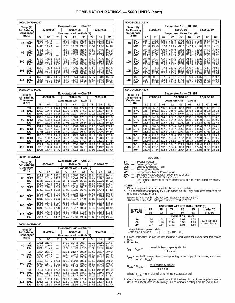
566D180/524A150
Temp (F)Air EnteringCondenser
(Edb)
Evaporator Air — Cfm/BF3750/0.06 5000/0.08 6250/0.10
Evaporator Air — Ewb (F)72 67 62 72 67 62 72 67 62
85TC 181.7 167.9 — 190.3 176.1 160.9 195.7 181.8 167.7SHC 90.5 113.0 — 100.8 128.3 160.8 110.2 144.5 167.7kW 14.85 14.20 — 15.25 14.59 13.87 15.51 14.86 14.19
95TC 175.1 161.7 — 183.0 169.5 155.6 188.0 174.9 162.2SHC 88.0 110.2 — 98.1 125.5 155.6 107.6 141.2 162.2kW 16.06 15.39 — 16.45 15.77 15.08 16.70 16.04 15.41
100TC 171.4 158.0 143.9 179.0 165.7 152.3 184.0 171.0 158.9SHC 86.5 108.5 136.4 96.6 123.9 152.3 106.2 139.4 158.9kW 16.68 15.93 15.13 17.11 16.36 15.60 17.39 16.65 15.97
105TC 168.2 155.3 142.0 175.3 162.6 150.0 180.0 167.6 156.4SHC 85.3 107.2 134.8 95.3 122.5 150.0 104.8 137.8 156.4kW 17.29 16.52 15.72 17.72 16.96 16.20 18.00 17.25 16.58
115TC 160.9 148.6 136.4 167.4 155.4 144.2 171.7 160.0 150.3SHC 82.5 104.1 130.0 92.4 119.4 144.2 102.0 134.2 150.3kW 18.54 17.75 16.97 18.96 18.19 17.47 19.24 18.48 17.86
566D180/524A180
Temp (F)Air EnteringCondenser
(Edb)
Evaporator Air — Cfm/BF4500/0.03 6000/0.05 7500/0.08
Evaporator Air — Ewb (F)72 67 62 72 67 62 72 67 62
85TC 196.7 181.4 167.0 204.2 190.6 177.3 209.9 196.4 184.8SHC 100.9 126.5 160.9 111.9 145.0 177.3 123.4 161.7 184.8kW 15.55 14.84 14.16 15.91 15.27 14.64 16.18 15.54 15.00
95TC 188.8 174.5 161.0 195.6 183.0 170.7 200.9 188.4 178.0SHC 98.2 123.4 155.6 108.7 141.4 170.7 120.2 157.7 178.0kW 16.74 16.03 15.35 17.08 16.45 15.84 17.35 16.72 16.20
100TC 184.7 170.6 157.4 191.3 179.0 167.0 196.6 184.3 174.2SHC 96.7 121.7 152.4 107.1 139.4 167.0 118.6 155.6 174.2kW 17.43 16.64 15.89 17.80 17.11 16.43 18.09 17.40 16.84
105TC 180.6 167.3 154.8 186.7 175.2 163.9 191.7 180.1 170.8SHC 95.3 120.2 150.1 105.4 137.6 163.9 116.9 153.6 170.8kW 18.04 17.24 16.49 18.40 17.71 17.03 18.70 18.01 17.45
115TC 172.1 159.8 148.1 177.5 167.0 156.7 182.1 171.5 163.3SHC 92.3 116.8 144.3 101.9 133.6 156.7 113.5 149.2 163.3kW 19.26 18.47 17.72 19.61 18.93 18.27 19.91 19.22 18.70
566D180/524A240
Temp (F)Air EnteringCondenser
(Edb)
Evaporator Air — Cfm/BF6000/0.03 8000/0.06 10,000/0.07
Evaporator Air — Ewb (F)72 67 62 72 67 62 72 67 62
85TC 214.1 198.7 185.1 221.3 206.0 195.8 224.4 212.1 204.4SHC 115.8 151.5 181.2 131.8 175.4 195.8 145.7 196.7 204.4kW 16.37 15.65 15.01 16.71 15.99 15.51 16.86 16.28 15.92
95TC 205.0 190.4 177.9 211.6 197.1 188.2 214.2 202.8 196.4SHC 112.3 148.1 175.0 128.3 171.6 188.2 142.1 192.5 196.4kW 17.55 16.82 16.20 17.88 17.15 16.71 18.01 17.44 17.12
100TC 200.6 186.2 174.0 207.1 192.6 184.2 209.6 198.4 192.5SHC 110.7 146.4 171.5 126.7 169.8 184.2 140.5 190.4 192.5kW 18.32 17.51 16.82 18.69 17.87 17.40 18.83 18.20 17.86
105TC 195.5 181.8 170.4 201.6 187.8 180.3 203.7 193.3 188.2SHC 108.7 144.6 168.4 124.7 167.7 180.3 138.4 188.1 188.2kW 18.93 18.11 17.43 19.29 18.47 18.02 19.42 18.80 18.49
115TC 185.7 172.9 162.6 191.2 178.3 172.0 192.9 183.4 179.5SHC 105.0 140.9 161.6 120.9 163.7 172.0 134.6 183.6 179.5kW 20.14 19.31 18.65 20.49 19.66 19.26 20.60 19.99 19.74
566D240/524A180
Temp (F)Air EnteringCondenser
(Edb)
Evaporator Air — Cfm/BF4500/0.03 6000/0.05 7500/0.08
Evaporator Air — Ewb (F)72 67 62 72 67 62 72 67 62
85TC 232.1 211.5 — 243.6 224.3 205.7 251.3 232.6 214.6SHC 113.4 140.0 — 126.7 161.4 205.7 138.2 179.8 214.6kW 19.33 18.26 — 19.93 18.93 17.95 20.33 19.36 18.42
95TC 221.4 201.5 — 232.1 213.7 196.0 239.6 221.7 204.9SHC 109.7 135.5 — 122.4 156.3 196.0 134.0 174.3 204.9kW 20.79 19.67 — 21.40 20.36 19.36 21.83 20.81 19.86
100TC 216.6 197.5 179.9 226.8 209.2 192.2 234.0 216.8 201.0SHC 108.0 133.7 172.2 120.4 154.1 192.2 132.0 171.9 201.0kW 21.48 20.35 19.31 22.08 21.04 20.04 22.50 21.49 20.55
105TC 211.1 192.4 175.1 221.0 203.8 187.3 228.1 211.2 196.0SHC 106.0 131.4 168.0 118.2 151.5 187.3 129.9 169.1 196.0kW 22.10 20.91 19.81 22.73 21.63 20.58 23.18 22.10 21.14
115TC 200.5 182.9 166.7 209.4 193.5 178.3 216.1 200.4 186.8SHC 102.3 127.2 160.6 113.9 146.5 178.3 125.6 163.7 186.8kW 23.38 22.12 20.96 24.02 22.88 21.79 24.49 23.37 22.40
566D240/524A240
Temp (F)Air EnteringCondenser
(Edb)
Evaporator Air — Cfm/BF6000/0.03 8000/0.06 10,000/0.07
Evaporator Air — Ewb (F)72 67 62 72 67 62 72 67 62
85TC 256.4 236.5 216.9 267.0 247.5 229.7 272.9 255.3 240.0SHC 131.9 167.0 208.9 148.3 192.9 229.7 162.8 216.4 240.0kW 20.60 19.56 18.54 21.15 20.13 19.21 21.46 20.54 19.75
95TC 224.8 225.2 206.5 255.0 235.6 219.4 260.3 243.3 229.7SHC 127.5 162.4 199.9 144.0 187.9 219.4 158.3 211.0 229.7kW 22.12 21.01 19.96 22.69 21.60 20.68 22.99 22.04 21.27
100TC 234.0 220.1 202.3 248.6 229.9 214.8 253.5 237.4 224.9SHC 125.3 160.3 196.2 141.7 185.5 214.8 156.0 208.2 224.9kW 22.80 21.68 20.63 23.37 22.26 21.37 23.66 22.70 21.97
105TC 233.1 214.3 197.1 242.5 223.9 209.6 247.1 231.3 219.6SHC 123.0 157.9 191.6 139.5 182.9 209.6 153.7 205.5 219.6kW 23.50 22.30 21.20 24.09 22.91 22.00 24.39 23.38 22.64
115TC 221.0 203.1 187.2 229.7 211.8 199.4 233.6 218.9 209.2SHC 118.4 153.3 183.1 134.8 177.8 199.4 149.0 199.8 209.2kW 24.84 23.56 22.43 25.46 24.18 23.30 25.74 24.69 24.00
566D240/524A300
Temp (F)Air EnteringCondenser
(Edb)
Evaporator Air — Cfm/BF7500/0.04 10,000/0.06 12,500/0.08
Evaporator Air — Ewb (F)72 67 62 72 67 62 72 67 62
85TC 275.0 253.1 235.5 284.8 262.9 249.6 289.9 271.6 261.5SHC 148.4 191.3 231.9 168.6 222.7 249.6 188.3 250.8 261.5kW 21.57 20.43 19.51 22.08 20.94 20.25 22.35 21.39 20.87
95TC 262.7 240.6 224.5 272.2 250.1 238.8 276.9 258.9 250.7SHC 143.9 186.3 221.9 164.2 217.4 238.8 184.0 245.3 250.6kW 23.13 21.88 20.97 23.67 22.42 21.78 23.93 22.91 22.45
100TC 256.1 234.5 219.6 265.0 243.6 233.5 269.4 252.1 245.1SHC 141.5 183.8 217.3 161.7 214.7 233.5 181.5 242.4 245.1kW 23.81 22.53 21.65 24.34 23.07 22.47 24.60 23.57 23.16
105TC 249.9 228.2 214.0 258.6 237.1 228.0 262.8 245.7 239.5SHC 139.2 181.2 212.2 159.4 212.1 228.0 179.3 239.5 239.5kW 24.56 23.18 22.28 25.12 23.75 23.17 25.39 24.30 23.91
115TC 236.6 215.4 203.1 244.7 223.8 216.8 248.4 232.1 228.0SHC 134.3 176.1 202.2 154.6 206.6 216.8 174.5 233.6 228.0kW 25.96 24.44 23.56 26.54 25.04 24.54 26.80 25.64 25.34
LEGENDBF — Bypass FactorEdb — Entering Dry BulbEER — Energy Efficiency RatioEwb — Entering Wet BulbkW — Compressor Motor Power InputSHC — Sensible Heat Capacity (1000 Btuh), GrossTC — Total Capacity (1000 Btuh), Gross— — Unit cannot operate at these conditions due to interruption by safety
control.NOTES:1. Direct interpolation is permissible. Do not extrapolate.2. The sensible heat capacity (SHC) is based on 80 F dry-bulb temperature of air
entering evaporator coil.Below 80 F dry-bulb, subtract (corr factor x cfm) from SHC.Above 80 F dry bulb, add (corr factor x cfm) to SHC.
BYPASSFACTOR
ENTERING-AIR DRY BULB TEMP (F)79 78 77 76 75 under 7581 82 83 84 85 over 85
Correction Factor.10 .99 1.98 2.97 3.96 4.95 Use formula
shown below..20 .88 1.76 2.64 3.52 4.40.30 .77 1.54 2.31 3.08 3.85
Interpolation is permissible.Correction Factor = 1.1 x (1 – BF) x (db – 80).
3. Gross capacities shown do not include a deduction for evaporator fan motorheat.
4. Formulas:
sensible heat capacity (Btuh)tldb = tedb −1.1 x cfm
tlwb = wet-bulb temperature corresponding to enthalpy of air leaving evapora-tor coil (hlwb).
total capacity (Btuh)hlwb = hewb −4.5 x cfm
where hewb = enthalpy of air entering evaporator coil
5. Combination ratings are based on a 2° F line loss. For a close-coupled system(less than 15 ft), add 2% to ratings. All combination ratings are based on R-22.
23
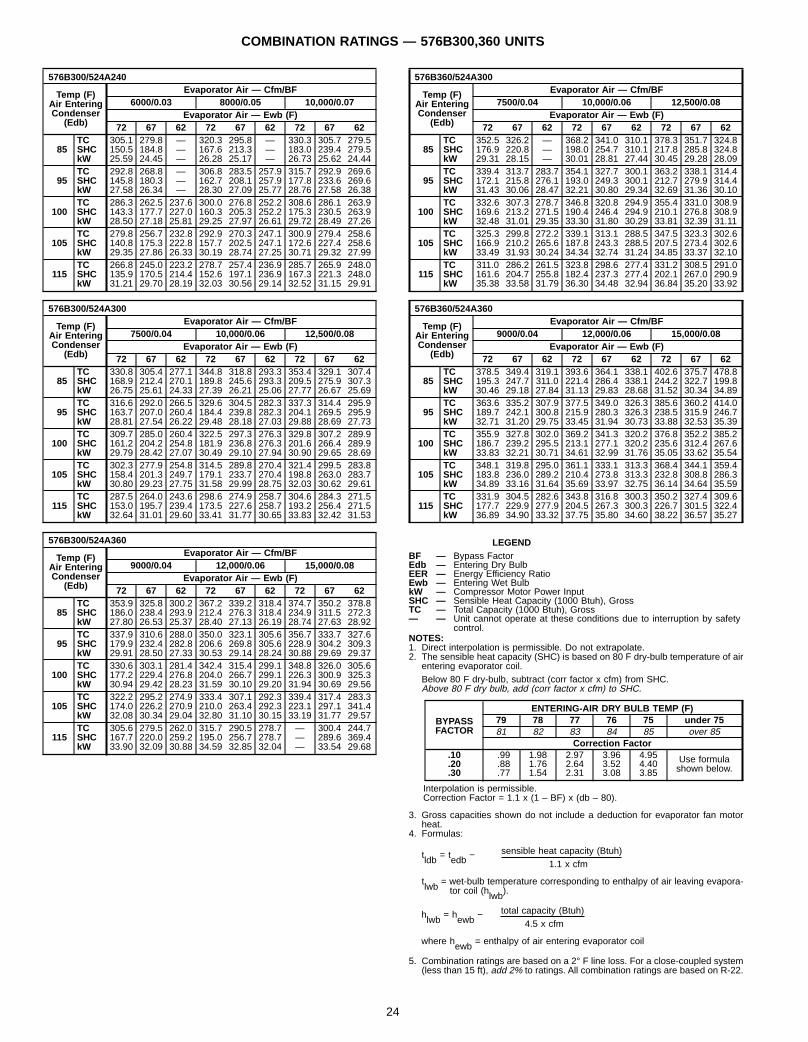
COMBINATION RATINGS — 576B300,360 UNITS
576B300/524A240
Temp (F)Air EnteringCondenser
(Edb)
Evaporator Air — Cfm/BF6000/0.03 8000/0.05 10,000/0.07
Evaporator Air — Ewb (F)72 67 62 72 67 62 72 67 62
85TC 305.1 279.8 — 320.3 295.8 — 330.3 305.7 279.5SHC 150.5 184.8 — 167.6 213.3 — 183.0 239.4 279.5kW 25.59 24.45 — 26.28 25.17 — 26.73 25.62 24.44
95TC 292.8 268.8 — 306.8 283.5 257.9 315.7 292.9 269.6SHC 145.8 180.3 — 162.7 208.1 257.9 177.8 233.6 269.6kW 27.58 26.34 — 28.30 27.09 25.77 28.76 27.58 26.38
100TC 286.3 262.5 237.6 300.0 276.8 252.2 308.6 286.1 263.9SHC 143.3 177.7 227.0 160.3 205.3 252.2 175.3 230.5 263.9kW 28.50 27.18 25.81 29.25 27.97 26.61 29.72 28.49 27.26
105TC 279.8 256.7 232.8 292.9 270.3 247.1 300.9 279.4 258.6SHC 140.8 175.3 222.8 157.7 202.5 247.1 172.6 227.4 258.6kW 29.35 27.86 26.33 30.19 28.74 27.25 30.71 29.32 27.99
115TC 266.8 245.0 223.2 278.7 257.4 236.9 285.7 265.9 248.0SHC 135.9 170.5 214.4 152.6 197.1 236.9 167.3 221.3 248.0kW 31.21 29.70 28.19 32.03 30.56 29.14 32.52 31.15 29.91
576B300/524A300
Temp (F)Air EnteringCondenser
(Edb)
Evaporator Air — Cfm/BF7500/0.04 10,000/0.06 12,500/0.08
Evaporator Air — Ewb (F)72 67 62 72 67 62 72 67 62
85TC 330.8 305.4 277.1 344.8 318.8 293.3 353.4 329.1 307.4SHC 168.9 212.4 270.1 189.8 245.6 293.3 209.5 275.9 307.3kW 26.75 25.61 24.33 27.39 26.21 25.06 27.77 26.67 25.69
95TC 316.6 292.0 266.5 329.6 304.5 282.3 337.3 314.4 295.9SHC 163.7 207.0 260.4 184.4 239.8 282.3 204.1 269.5 295.9kW 28.81 27.54 26.22 29.48 28.18 27.03 29.88 28.69 27.73
100TC 309.7 285.0 260.4 322.5 297.3 276.3 329.8 307.2 289.9SHC 161.2 204.2 254.8 181.9 236.8 276.3 201.6 266.4 289.9kW 29.79 28.42 27.07 30.49 29.10 27.94 30.90 29.65 28.69
105TC 302.3 277.9 254.8 314.5 289.8 270.4 321.4 299.5 283.8SHC 158.4 201.3 249.7 179.1 233.7 270.4 198.8 263.0 283.7kW 30.80 29.23 27.75 31.58 29.99 28.75 32.03 30.62 29.61
115TC 287.5 264.0 243.6 298.6 274.9 258.7 304.6 284.3 271.5SHC 153.0 195.7 239.4 173.5 227.6 258.7 193.2 256.4 271.5kW 32.64 31.01 29.60 33.41 31.77 30.65 33.83 32.42 31.53
576B300/524A360
Temp (F)Air EnteringCondenser
(Edb)
Evaporator Air — Cfm/BF9000/0.04 12,000/0.06 15,000/0.08
Evaporator Air — Ewb (F)72 67 62 72 67 62 72 67 62
85TC 353.9 325.8 300.2 367.2 339.2 318.4 374.7 350.2 378.8SHC 186.0 238.4 293.9 212.4 276.3 318.4 234.9 311.5 272.3kW 27.80 26.53 25.37 28.40 27.13 26.19 28.74 27.63 28.92
95TC 337.9 310.6 288.0 350.0 323.1 305.6 356.7 333.7 327.6SHC 179.9 232.4 282.8 206.6 269.8 305.6 228.9 304.2 309.3kW 29.91 28.50 27.33 30.53 29.14 28.24 30.88 29.69 29.37
100TC 330.6 303.1 281.4 342.4 315.4 299.1 348.8 326.0 305.6SHC 177.2 229.4 276.8 204.0 266.7 299.1 226.3 300.9 325.3kW 30.94 29.42 28.23 31.59 30.10 29.20 31.94 30.69 29.56
105TC 322.2 295.2 274.9 333.4 307.1 292.3 339.4 317.4 283.3SHC 174.0 226.2 270.9 210.0 263.4 292.3 223.1 297.1 341.4kW 32.08 30.34 29.04 32.80 31.10 30.15 33.19 31.77 29.57
115TC 305.6 279.5 262.0 315.7 290.5 278.7 — 300.4 244.7SHC 167.7 220.0 259.2 195.0 256.7 278.7 — 289.6 369.4kW 33.90 32.09 30.88 34.59 32.85 32.04 — 33.54 29.68
576B360/524A300
Temp (F)Air EnteringCondenser
(Edb)
Evaporator Air — Cfm/BF7500/0.04 10,000/0.06 12,500/0.08
Evaporator Air — Ewb (F)72 67 62 72 67 62 72 67 62
85TC 352.5 326.2 — 368.2 341.0 310.1 378.3 351.7 324.8SHC 176.9 220.8 — 198.0 254.7 310.1 217.8 285.8 324.8kW 29.31 28.15 — 30.01 28.81 27.44 30.45 29.28 28.09
95TC 339.4 313.7 283.7 354.1 327.7 300.1 363.2 338.1 314.4SHC 172.1 215.8 276.1 193.0 249.3 300.1 212.7 279.9 314.4kW 31.43 30.06 28.47 32.21 30.80 29.34 32.69 31.36 30.10
100TC 332.6 307.3 278.7 346.8 320.8 294.9 355.4 331.0 308.9SHC 169.6 213.2 271.5 190.4 246.4 294.9 210.1 276.8 308.9kW 32.48 31.01 29.35 33.30 31.80 30.29 33.81 32.39 31.11
105TC 325.3 299.8 272.2 339.1 313.1 288.5 347.5 323.3 302.6SHC 166.9 210.2 265.6 187.8 243.3 288.5 207.5 273.4 302.6kW 33.49 31.93 30.24 34.34 32.74 31.24 34.85 33.37 32.10
115TC 311.0 286.2 261.5 323.8 298.6 277.4 331.2 308.5 291.0SHC 161.6 204.7 255.8 182.4 237.3 277.4 202.1 267.0 290.9kW 35.38 33.58 31.79 36.30 34.48 32.94 36.84 35.20 33.92
576B360/524A360
Temp (F)Air EnteringCondenser
(Edb)
Evaporator Air — Cfm/BF9000/0.04 12,000/0.06 15,000/0.08
Evaporator Air — Ewb (F)72 67 62 72 67 62 72 67 62
85TC 378.5 349.4 319.1 393.6 364.1 338.1 402.6 375.7 478.8SHC 195.3 247.7 311.0 221.4 286.4 338.1 244.2 322.7 199.8kW 30.46 29.18 27.84 31.13 29.83 28.68 31.52 30.34 34.89
95TC 363.6 335.2 307.9 377.5 349.0 326.3 385.6 360.2 414.0SHC 189.7 242.1 300.8 215.9 280.3 326.3 238.5 315.9 246.7kW 32.71 31.20 29.75 33.45 31.94 30.73 33.88 32.53 35.39
100TC 355.9 327.8 302.0 369.2 341.3 320.2 376.8 352.2 385.2SHC 186.7 239.2 295.5 213.1 277.1 320.2 235.6 312.4 267.6kW 33.83 32.21 30.71 34.61 32.99 31.76 35.05 33.62 35.54
105TC 348.1 319.8 295.0 361.1 333.1 313.3 368.4 344.1 359.4SHC 183.8 236.0 289.2 210.4 273.8 313.3 232.8 308.8 286.3kW 34.89 33.16 31.64 35.69 33.97 32.75 36.14 34.64 35.59
115TC 331.9 304.5 282.6 343.8 316.8 300.3 350.2 327.4 309.6SHC 177.7 229.9 277.9 204.5 267.3 300.3 226.7 301.5 322.4kW 36.89 34.90 33.32 37.75 35.80 34.60 38.22 36.57 35.27
LEGENDBF — Bypass FactorEdb — Entering Dry BulbEER — Energy Efficiency RatioEwb — Entering Wet BulbkW — Compressor Motor Power InputSHC — Sensible Heat Capacity (1000 Btuh), GrossTC — Total Capacity (1000 Btuh), Gross— — Unit cannot operate at these conditions due to interruption by safety
control.NOTES:1. Direct interpolation is permissible. Do not extrapolate.2. The sensible heat capacity (SHC) is based on 80 F dry-bulb temperature of air
entering evaporator coil.Below 80 F dry-bulb, subtract (corr factor x cfm) from SHC.Above 80 F dry bulb, add (corr factor x cfm) to SHC.
BYPASSFACTOR
ENTERING-AIR DRY BULB TEMP (F)79 78 77 76 75 under 7581 82 83 84 85 over 85
Correction Factor.10 .99 1.98 2.97 3.96 4.95 Use formula
shown below..20 .88 1.76 2.64 3.52 4.40.30 .77 1.54 2.31 3.08 3.85
Interpolation is permissible.Correction Factor = 1.1 x (1 – BF) x (db – 80).
3. Gross capacities shown do not include a deduction for evaporator fan motorheat.
4. Formulas:
sensible heat capacity (Btuh)tldb = tedb −1.1 x cfm
tlwb = wet-bulb temperature corresponding to enthalpy of air leaving evapora-tor coil (hlwb).
total capacity (Btuh)hlwb = hewb −4.5 x cfm
where hewb = enthalpy of air entering evaporator coil
5. Combination ratings are based on a 2° F line loss. For a close-coupled system(less than 15 ft), add 2% to ratings. All combination ratings are based on R-22.
24

HYDRONIC HEATING CAPACITIES — 524A
UNIT524A
AIRFLOW(Cfm)
1-ROWSTEAM*
2-ROWHOT WATER COIL†
Cap. Ldb Cap. Ldb Gpm PD
0721,8002,4003,000
146173209
134126123
156.0183.0206.0
140131124
15.618.320.6
3.44.35.2
0902,2503,0003,750
168209240
129123117
174.0206.0238.0
133124118
17.420.623.8
4.05.26.5
1203,0004,0005,000
209243279
123115111
299.0275.0316.0
152124119
29.927.531.6
5.06.68.2
1503,7505,0006,250
370425465
150137128
362.0409.0456.0
149136128
36.240.945.6
4.25.16.0
1804,5006,0007,500
402458479
141129118
412.0471.0529.0
145133125
41.247.152.9
4.55.56.6
2406,0008,00010,000
458487499
129115105
506.0584.0652.0
138128120
50.658.465.2
5.16.37.5
3007,50010,00012,500
511575626
122112106
649.0752.0842.0
140130122
64.975.284.2
5.77.18.5
3609,00012,00015,000
560621670
117107101
735.0850.0950.0
136126119
73.585.095.0
6.27.89.3
LEGENDCap. — Capacity (Btuh in thousands)Ldb — Leaving-Air Dry-Bulb Temp (F)PD — Pressure Drop (ft water)*Based on 5 psig steam, 60 F entering-air temperature. All steam coils are non-freeze type.†Based on 200 F entering water, 20 F water temperature drop, 60 F entering-air temperature.
NOTES:1. Maximum operating limits for steam heating coils: 175 psig at 400 F. Maximum operating limit for hot water coils is 150 psig.2. Capacity (Btuh)Leaving db =ent db (F) +
1.1 x cfm3. See Heating Correction Factors tables below.
HEATING CORRECTION FACTORS — 524AHOT WATER COIL
Water TempDrop(F)
Ent WaterTemp(F)
Entering-Air Temp (F)
40 50 60 70 80
10
140 0.72 0.64 0.57 0.49 0.41160 0.89 0.81 0.74 0.66 0.58180 1.06 0.98 0.90 0.83 0.75200 1.22 1.15 1.07 1.00 0.92220 1.39 1.32 1.24 1.17 1.09
20
140 0.64 0.57 0.49 0.41 0.33160 0.81 0.74 0.66 0.58 0.51180 0.98 0.91 0.83 0.75 0.68200 1.15 1.08 1.00 0.93 0.85220 1.32 1.25 1.17 1.10 1.02
30
140 0.56 0.49 0.41 0.33 0.24160 0.74 0.66 0.58 0.51 0.43180 0.91 0.83 0.76 0.68 0.60200 1.08 1.00 0.93 0.85 0.78220 1.25 1.18 1.10 1.03 0.95
NOTE: Multiply capacity given in the Hydronic Heating Capacities table by the cor-rection factor for conditions at which unit is actually operating. Correct leaving-airtemperature using formula in Note 2 of Hydronic Heating Capacities table.
STEAM COIL
Steam Pressure(psig)
Entering-Air Temp (F)40 50 60 70 80
0 1.06 0.98 0.91 0.85 0.782 1.09 1.02 0.95 0.89 0.825 1.13 1.06 1.00 0.93 0.87
NOTE: Multiply capacity given in the Hydronic Heating Capacities table by the cor-rection factor for conditions at which unit is actually operating. Correct leaving-airtemperature using formula in Note 2 of Hydronic Heating Capacities table.
25

AIR DELIVERY — 524A (0.0-1.2 ESP)
UNIT524A
AIRFLOW(Cfm)
EXTERNAL STATIC PRESSURE (in. wg)0.0 0.2 0.4 0.6 0.8 1.0 1.2
Rpm Bhp Rpm Bhp Rpm Bhp Rpm Bhp Rpm Bhp Rpm Bhp Rpm Bhp
072
1,800 320 0.22 442 0.32 534 0.42 611 0.52 678 0.61 739 0.70 795 0.802,100 373 0.31 483 0.42 569 0.53 642 0.63 708 0.73 767 0.82 821 0.922,400 427 0.42 526 0.53 606 0.64 676 0.75 739 0.86 796 0.96 849 1.062,700 480 0.54 570 0.67 646 0.78 712 0.89 773 1.00 828 1.11 880 1.213,000 533 0.69 616 0.82 687 0.94 750 1.05 808 1.16 862 1.28 912 1.39
090
2,250 359 0.32 472 0.44 560 0.55 634 0.65 700 0.75 759 0.86 814 0.962,600 415 0.45 516 0.57 599 0.68 669 0.79 732 0.90 790 1.01 843 1.113,000 478 0.62 569 0.75 645 0.86 712 0.98 773 1.09 828 1.20 879 1.323,400 542 0.82 624 0.95 695 1.08 758 1.20 815 1.31 869 1.43 918 1.553,750 598 1.03 673 1.17 740 1.29 800 1.42 855 1.60 906 1.66 954 1.78
120
3,000 444 0.58 541 0.71 621 0.83 691 0.94 753 1.05 809 1.17 862 1.283,500 518 0.82 604 0.95 677 1.08 742 1.20 801 1.32 855 1.44 906 1.564,000 592 1.11 669 1.25 736 1.38 797 1.51 853 1.63 904 1.75 953 1.884,500 666 1.44 735 1.59 797 1.72 854 1.86 907 1.99 956 2.12 1003 2.245,000 740 1.83 803 1.98 861 2.12 914 2.26 964 2.39 1010 2.53 1055 2.66
150
3,750 363 0.37 475 0.58 566 0.80 645 1.02 715 1.24 779 1.47 839 1.694,300 416 0.53 517 0.78 601 1.02 676 1.26 743 1.50 805 1.74 862 1.995,000 484 0.81 573 1.08 650 1.35 719 1.62 782 1.89 841 2.16 896 2.445,700 552 1.17 631 1.47 702 1.76 766 2.06 826 2.36 881 2.66 934 2.966,250 605 1.51 678 1.83 744 2.15 805 2.47 862 2.79 915 3.11 966 3.43
180
4,500 391 0.51 495 0.75 581 1.00 657 1.25 725 1.50 787 1.76 845 2.025,300 460 0.80 551 1.08 629 1.35 700 1.63 764 1.91 823 2.20 878 2.486,000 521 1.13 602 1.43 675 1.73 741 2.04 801 2.34 858 2.65 911 2.966,800 590 1.60 663 1.93 730 2.26 791 2.59 847 2.92 901 3.26 951 3.607,500 651 2.10 718 2.45 779 2.81 837 3.16 890 3.52 941 3.88 990 4.24
240
6,000 503 1.07 587 1.37 661 1.67 727 1.97 789 2.28 846 2.59 900 2.907,000 586 1.64 660 1.98 726 2.31 787 2.65 844 2.99 898 3.33 948 3.678,000 670 2.37 735 2.74 795 3.12 851 3.49 904 3.86 954 4.23 1001 4.619,000 754 3.28 812 3.69 867 4.09 918 4.50 967 4.90 1014 5.31 1059 5.7210,000 838 4.39 891 4.83 941 5.27 988 5.70 1034 6.14 1077 6.85 1120 7.02
300
7,500 412 1.15 492 1.53 568 2.00 640 2.56 710 3.22 776 3.98 840 4.838,750 481 1.76 550 2.17 616 2.66 680 3.22 742 3.86 802 4.58 860 5.3810,000 549 2.55 610 2.99 669 3.50 726 4.07 782 4.70 836 5.40 889 6.1711,250 618 3.52 672 4.00 725 4.53 777 5.12 827 5.76 876 6.45 925 7.2112,500 687 4.71 735 5.22 783 5.78 830 6.38 876 7.04 922 7.74 966 8.49
360
9,000 471 1.78 539 2.17 604 2.63 667 3.17 728 3.78 788 4.46 845 5.2210,500 550 2.72 608 3.15 665 3.64 720 4.18 774 4.79 827 5.45 878 6.1812,000 628 3.93 679 4.40 730 4.92 779 5.48 827 6.09 874 6.76 921 7.4713,500 707 5.44 752 5.94 797 6.49 841 7.08 885 7.71 928 8.38 970 9.1015,000 785 7.27 826 7.81 867 8.39 907 9.01 947 9.66 986 10.35 1024 11.07
26

LEGENDBhp — Brake Horsepower Input to FanESP — External Static Pressure
Italic type indicates special field-supplied drive required for use withstandard motor.Bold indicates standard drive and standard motor.Plain type indicates medium-static drive and standard motor. For524A300 size only, plain type indicates medium-static drive and alter-nate motor.
indicates high-static drive and alternate motor. For 524A360size and single-phase 090 size, shading indicates high-static drive andstandard motor.
NOTES:1. Maximum allowable fan speed is 1100 rpm for unit sizes 300 and
360; 1200 rpm for all other sizes.2. Fan performance is based on deductions for wet coil, clean 2-in. fil-
ters, and unit casing. See below for factory-supplied filter pressuredrop.
3. Refer to fan motor and drives tables, pages 48-50 to complete theselection.
4. Alternate motor not available for 360 size units or single-phase 090size units.
FACTORY-SUPPLIED FILTER PRESSURE DROP (in. wg)
UNIT524A
AIRFLOW(Cfm)
PRESSURE DROP(in. wg)
0721,8002,4003,000
0.050.080.11
0902,2503,0003,750
0.070.110.15
1203,0004,0005,000
0.110.170.23
1503,7505,0006,250
0.060.100.13
1804,5006,0007,500
0.080.120.17
2406,0008,00010,000
0.120.190.26
3007,50010,00012,500
0.150.220.30
3609,00012,00015,000
0.190.290.40
27

AIR DELIVERY — 524A (1.4-2.4 ESP)
UNIT524A
AIRFLOW(Cfm)
EXTERNAL STATIC PRESSURE (in. wg)1.4 1.6 1.8 2.0 2.2 2.4
Rpm Bhp Rpm Bhp Rpm Bhp Rpm Bhp Rpm Bhp Rpm Bhp
072
1,800 847 0.89 896 0.98 942 1.07 986 1.16 1027 1.25 — —2,100 872 1.02 920 1.11 965 1.21 1008 1.30 1050 1.40 — —2,400 899 1.16 946 1.26 990 1.36 1033 1.46 1073 1.55 — —2,700 928 1.32 974 1.42 1018 1.52 1059 1.63 1099 1.73 — —3,000 959 1.49 1004 1.60 1046 1.71 1087 1.81 1126 1.92 — —
090
2,250 865 1.06 913 1.16 958 1.27 1001 1.37 1042 1.47 — —2,600 893 1.22 940 1.33 984 1.43 1027 1.54 1067 1.65 — —3,000 928 1.43 973 1.54 1017 1.65 1058 1.76 1098 1.87 — —3,400 965 1.66 1010 1.78 1052 1.89 1092 2.00 1131 2.12 — —3,750 1000 1.90 1043 2.02 1084 2.13 1124 2.25 1162 2.37 — —
120
3,000 911 1.39 958 1.50 1002 1.61 1044 1.72 1084 1.83 1123 1.943,500 953 1.67 998 1.79 1041 1.90 1082 2.02 1122 2.13 1159 2.254,000 999 2.00 1042 2.12 1084 2.24 1124 2.36 1162 2.48 1199 2.604,500 1047 2.37 1089 2.50 1129 2.62 1168 2.74 — — — —5,000 1097 2.79 1138 2.92 1177 3.05 — — — — — —
150
3,750 894 1.91 947 2.14 996 2.37 1044 2.60 1089 2.83 — —4,300 916 2.23 967 2.48 1016 2.73 1062 2.98 1107 3.24 — —5,000 948 2.71 997 2.98 1044 3.26 1089 3.53 1133 3.81 — —5,700 984 3.25 1031 3.55 1076 3.86 1120 4.16 1162 4.46 — —6,250 1014 3.75 1060 4.07 1104 4.39 1147 4.71 1188 5.03 — —
180
4,500 899 2.29 951 2.56 999 2.84 1046 3.12 1091 3.41 1133 3.705,300 930 2.78 980 3.08 1027 3.38 1072 3.68 1116 3.99 1157 4.306,000 961 3.28 1009 3.60 1055 3.92 1098 4.24 1141 4.57 1181 4.916,800 999 3.94 1045 4.28 1089 4.63 1132 4.98 1173 5.33 — —7,500 1036 4.60 1080 4.97 1123 5.34 1164 5.71 — — — —
240
6,000 950 3.21 999 3.53 1045 3.85 1089 4.17 1131 4.50 1172 4.837,000 996 4.02 1042 4.37 1086 4.72 1129 5.07 1169 5.43 — —8,000 1047 4.99 1091 5.37 1133 5.75 1173 6.13 — — — —9,000 1102 6.13 1143 6.54 1183 6.96 — — — — — —10,000 1160 7.46 1200 7.91 — — — — — — — —
300
7,500 903 5.79 963 6.83 1021 7.98 1078 9.21 — — — —8,750 917 6.26 972 7.22 1025 8.26 1078 9.38 — — — —10,000 941 7.01 991 7.91 1040 8.89 1089 9.93 — — — —11,250 972 8.02 1019 8.89 1064 9.83 — — — — — —12,500 1010 9.29 1053 10.15 1095 11.05 — — — — — —
360
9,000 901 6.07 955 6.98 1008 7.98 1060 9.05 — — — —10,500 928 6.98 978 7.84 1026 8.76 1073 9.74 — — — —12,000 966 8.24 1011 9.07 1055 9.95 1098 10.88 — — — —13,500 1011 9.86 1052 10.67 1092 11.52 — — — — — —15,000 1062 11.84 — — — — — — — — — —
LEGENDBhp — Brake Horsepower Input to FanESP — External Static Pressure
Plain type indicates medium-static drive and standard motor. For524A300 size only, plain type indicates medium-static drive and alter-nate motor.
indicates high-static drive and alternate motor. For 524A360size and single-phase 090 size, shading indicates high-static drive andstandard motor.Italics indicate special field-supplied drive required for use with alternatemotor. For 524A360 size only, italics indicate special field-supplied driverequired for use with standard motor.Bold indicates special field-supplied drive and motor.
NOTES:1. Maximum allowable fan speed is 1100 rpm for unit sizes 300 and
360; 1200 rpm for all other sizes.2. Fan performance is based on deductions for wet coil, clean 2-in. fil-
ters, and unit casing. See page 27 for factory-supplied filter pressuredrop.
3. Refer to fan motor and drives tables, pages 48-50 to complete theselection.
4. Alternate motor not available for 360 size units or single-phase 090size units.
28
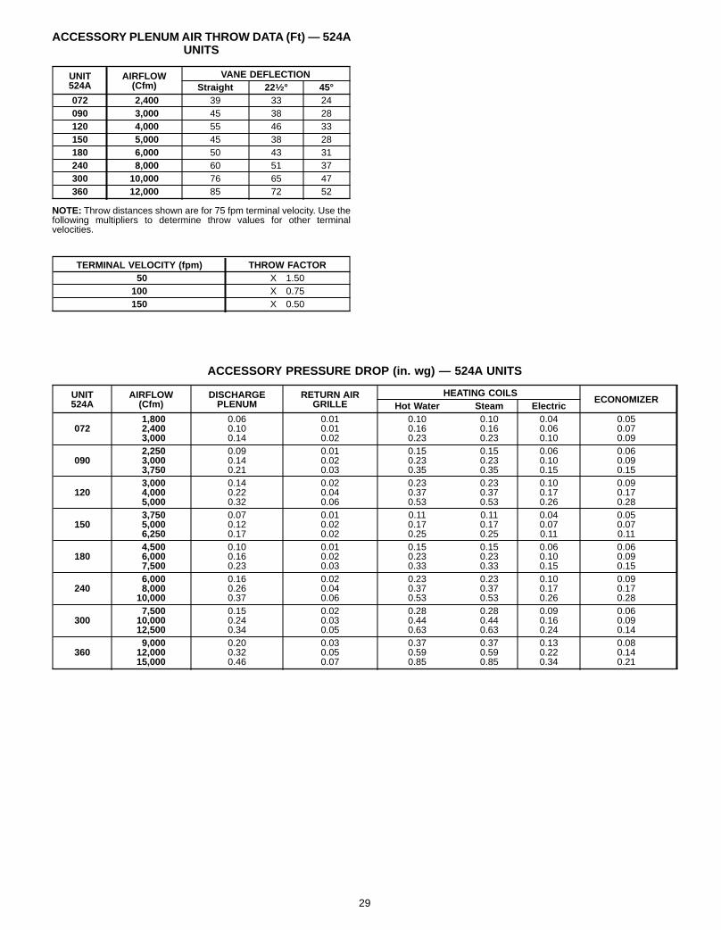
ACCESSORY PLENUMAIR THROW DATA (Ft) — 524AUNITS
UNIT524A
AIRFLOW(Cfm)
VANE DEFLECTIONStraight 22 1⁄2° 45°
072 2,400 39 33 24090 3,000 45 38 28120 4,000 55 46 33150 5,000 45 38 28180 6,000 50 43 31240 8,000 60 51 37300 10,000 76 65 47360 12,000 85 72 52
NOTE: Throw distances shown are for 75 fpm terminal velocity. Use thefollowing multipliers to determine throw values for other terminalvelocities.
TERMINAL VELOCITY (fpm) THROW FACTOR50 X 1.50100 X 0.75150 X 0.50
ACCESSORY PRESSURE DROP (in. wg) — 524A UNITS
UNIT524A
AIRFLOW(Cfm)
DISCHARGEPLENUM
RETURN AIRGRILLE
HEATING COILSECONOMIZER
Hot Water Steam Electric
0721,8002,4003,000
0.060.100.14
0.010.010.02
0.100.160.23
0.100.160.23
0.040.060.10
0.050.070.09
0902,2503,0003,750
0.090.140.21
0.010.020.03
0.150.230.35
0.150.230.35
0.060.100.15
0.060.090.15
1203,0004,0005,000
0.140.220.32
0.020.040.06
0.230.370.53
0.230.370.53
0.100.170.26
0.090.170.28
1503,7505,0006,250
0.070.120.17
0.010.020.02
0.110.170.25
0.110.170.25
0.040.070.11
0.050.070.11
1804,5006,0007,500
0.100.160.23
0.010.020.03
0.150.230.33
0.150.230.33
0.060.100.15
0.060.090.15
2406,0008,00010,000
0.160.260.37
0.020.040.06
0.230.370.53
0.230.370.53
0.100.170.26
0.090.170.28
3007,50010,00012,500
0.150.240.34
0.020.030.05
0.280.440.63
0.280.440.63
0.090.160.24
0.060.090.14
3609,00012,00015,000
0.200.320.46
0.030.050.07
0.370.590.85
0.370.590.85
0.130.220.34
0.080.140.21
29

ELECTRICAL DATA
569C UNITS
UNIT 569C NOMINAL VOLTAGE(V-Ph-Hz)
VOLTAGE RANGE* COMPR OFM POWER SUPPLYMin Max RLA LRA FLA MCA MOCP
072 208/230-3-60 187 254 19.0 142 1.9 25.6 35460-3-60 414 508 9.5 72 1.0 12.9 15
090 208/230-3-60 187 254 25.0 185 3.1 34.4 45460-3-60 414 508 12.4 89 1.4 16.9 20
120 208/230-3-60 187 254 34.5 239 3.1 46.2 60460-3-60 414 508 17.0 119 1.4 22.7 30
576B090-120 UNITS
UNIT576B
NOMINAL VOLTAGE(V-Ph-Hz)
VOLTAGE RANGE* COMPR OFM POWER SUPPLYMin Max RLA LRA FLA MCA MOCP
090208/230-3-60 187 254 31.5 160 3.1 42.5 50460-3-60 414 508 15.7 80 1.4 21.0 25575-3-60 518 632 12.6 64 1.4 17.2 20
102208/230-3-60 187 254 39.7 198 3.1 52.7 70460-3-60 414 508 19.9 99 1.4 26.3 35575-3-60 518 632 15.9 79 1.4 21.3 25
120208/230-3-60 187 254 39.7 198 3.1 52.7 70460-3-60 414 508 19.9 99 1.4 26.3 35575-3-60 518 632 15.9 79 1.4 21.3 25
566D UNITS
UNIT566D
NOMINAL VOLTAGE(V-Ph-Hz)
VOLTAGE RANGE* COMPR OFM POWER SUPPLY
Min Max RLA LRA Qty Nom.Hp
FLA (ea)Fan No. MCA MOCP
(Fuse)1 2
120 208/230-3-60 187 253 43.6 170 2 1⁄2 4.3 3.7 62.5 100460-3-60 414 528 20.0 77 2.3 1.9 29.1 40
150 208/230-3-60 187 253 49.3 191 2 1⁄2 4.3 3.7 69.3 100460-3-60 414 528 22.1 80 2.3 1.9 31.7 50
180 208/230-3-60 187 253 63.6 266 2 1⁄2 4.3 3.7 87.5 125460-3-60 414 528 29.3 120 2.3 1.9 40.7 60
240208/230-3-60 187 254 67.9 345
2 1⁄24.3 3.7 93.4 161
460-3-60 414 508 34.7 173 2.3 1.9 48.1 82575-3-60 518 632 28.8 120 1.8 1.8 40.1 68
LEGENDCSA — Canadian Standards AssociationFLA — Full Load AmpsHACR — Heating, Air Conditioning and RefrigerationLRA — Locked Rotor AmpsMCA — Minimum Circuit AmpsMOCP — Maximum Overcurrent ProtectionNEC — National Electrical CodeOFM — Outdoor (Condenser) Fan MotorRLA — Rated Load AmpsUL — Underwriters’ Laboratories
*Units are suitable for use on electrical systems where voltage suppliedto the unit terminals is not below or above the listed limits.
NOTES:1. In compliance with NEC requirements for multimotor and combina-
tion load equipment (refer to NEC Articles 430 and 440), the over-current protective device shall be fuse or HACR breaker.
2. The 575-v units are CSA listed only.
30
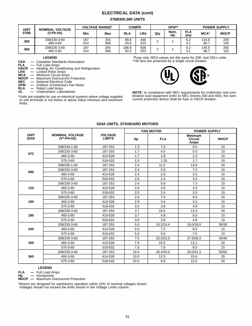
ELECTRICAL DATA (cont)
576B300,360 UNITS
UNIT576B
NOMINAL VOLTAGE(V-Ph-Hz)
VOLTAGE RANGE* COMPR OFM** POWER SUPPLY
Min Max RLA LRA Qty Nom.Hp
FLA(ea) MCA† MOCP
300 208/230-3-60 187 254 89.8 446 2 1 6.2 124.6 200460-3-60 414 508 43.6 223 3.1 60.7 100
360 208/230-3-60 187 254 106.5 506 2 1 6.2 145.5 250460-3-60 414 508 50.0 253 3.1 68.7 110
LEGENDCSA — Canadian Standards AssociationFLA — Full Load AmpsHACR — Heating, Air Conditioning and RefrigerationLRA — Locked Rotor AmpsMCA — Minimum Circuit AmpsMOCP — Maximum Overcurrent ProtectionNEC — National Electrical CodeOFM — Outdoor (Condenser) Fan MotorRLA — Rated Load AmpsUL — Underwriters’ Laboratories
*Units are suitable for use on electrical systems where voltage suppliedto unit terminals is not below or above listed minimum and maximumlimits.
†Fuse only. MCA values are the same for 208- and 230-v units.**All fans are protected by a single circuit breaker.
NOTE: In compliance with NEC requirements for multimotor and com-bination load equipment (refer to NEC Articles 430 and 440), the over-current protective device shall be fuse or HACR breaker.
524A UNITS, STANDARD MOTORS
UNIT524A
NOMINAL VOLTAGE(V*-PH-HZ)
VOLTAGELIMITS
FAN MOTOR POWER SUPPLY
Hp FLAMinimumCircuitAmps
MOCP
072
208/230-1-60 187-253 1.3 7.6 9.5 15208/230-3-60 187-253 1.7 4.0 5.0 15460-3-60 414-528 1.7 1.8 2.3 15575-3-60 518-632 1.0 1.35 1.7 15
090
208/230-1-60 187-253 2.4 11.0 13.8 20208/230-3-60 187-253 2.4 5.8 7.3 15460-3-60 414-528 2.4 2.6 3.3 15575-3-60 518-632 2.0 2.4 3.0 15
120208/230-3-60 187-253 2.4 5.8 7.3 15460-3-60 414-528 2.4 2.6 3.3 15575-3-60 518-632 2.0 2.4 3.0 15
150208/230-3-60 187-253 2.9 7.5 9.4 15460-3-60 414-528 2.9 3.4 4.3 15575-3-60 518-632 3.0 3.8 4.8 15
180208/230-3-60 187-253 3.7 10.6 13.3 20460-3-60 414-528 3.7 4.8 6.0 15575-3-60 518-632 3.0 3.8 4.8 15
240208/230-3-60 187-253 5.0 15.2/14.4 19.0/18.0 30/30460-3-60 414-528 5.0 7.2 9.0 15575-3-60 518-632 5.0 5.6 7.0 15
300208/230-3-60 187-253 7.5 22.0/21.0 27.5/26.3 45/45460-3-60 414-528 7.5 10.5 13.1 20575-3-60 518-632 7.5 7.6 9.5 15
360208/230-3-60 187-253 10.0 26.4/25.0 33.0/31.3 55/55460-3-60 414-528 10.0 12.5 15.6 25575-3-60 518-632 10.0 9.6 12.0 20
LEGENDFLA — Full Load AmpsHp — HorsepowerMOCP — Maximum Overcurrent Protection
*Motors are designed for satisfactory operation within 10% of nominal voltages shown.Voltages should not exceed the limits shown in the Voltage Limits column.
31

ELECTRICAL DATA (cont)
524A UNITS, ALTERNATE MOTORS
UNIT524A
NOMINAL VOLTAGE(V*-PH-HZ)
VOLTAGELIMITS
FAN MOTOR POWER SUPPLY
Hp FLAMinimumCircuitAmps
MOCP
072
208/230-1-60 187-253 2.4 11.0 13.8 20208/230-3-60 187-253 2.9 7.5 9.4 15460-3-60 414-528 2.9 3.4 4.3 15575-3-60 518-632 2.0 2.4 3.0 15
090208/230-3-60 187-253 2.9 7.5 9.4 15460-3-60 414-528 2.9 3.4 4.3 15575-3-60 518-632 3.0 2.4 3.0 15
120208/230-3-60 187-253 3.7 10.6 13.3 20460-3-60 414-528 3.7 4.8 6.0 15575-3-60 518-632 3.0 3.8 4.8 15
150208/230-3-60 187-253 3.7 10.6 13.3 20460-3-60 414-528 3.7 4.8 6.0 15575-3-60 518-632 5.0 5.6 7.0 15
180208/230-3-60 187-253 5.0 15.2/14.4 19.9/18.0 30/30460-3-60 414-528 5.0 7.2 6.0 15575-3-60 518-632 5.0 5.6 4.8 15
240208/230-3-60 187-253 7.5 22.0/21.0 27.5/26.3 45/45460-3-60 414-528 7.5 10.5 13.1 20575-3-60 518-632 7.5 7.6 9.5 15
300208/230-3-60 187-253 10.0 26.4/25.0 33.0/31.3 55/55460-3-60 414-528 10.0 12.5 15.6 25575-3-60 518-632 10.0 9.6 12.0 20
LEGENDFLA — Full Load AmpsHp — HorsepowerMOCP — Maximum Overcurrent Protection
*Motors are designed for satisfactory operation within 10% of nominal voltages shown.Voltages should not exceed the limits shown in the Voltage Limits column.
32

ELECTRIC HEATER DATA — 524A UNITS
UNIT 524A HEATERPART NO. V-PH-HZ NOMINAL kW HEATER
AMPS MCA* MOCP*
072-120
CAELHEAT001A00 240-3-605
12.0 25.6 30CAELHEAT002A00 480-3-60 6.0 12.3 15CAELHEAT003A00 575-3-60 5.0 11.9 15CAELHEAT004A00 240-3-60
1024.1 40.7 50
CAELHEAT005A00 480-3-60 12.0 17.8 25CAELHEAT006A00 575-3-60 10.0 18.1 25CAELHEAT007A00 240-3-60
1536.0 55.7 80
CAELHEAT008A00 480-3-60 18.0 27.4 40CAELHEAT009A00 575-3-60 15.1 24.4 35CAELHEAT010A00 240-3-60
2560.1 85.8 125
CAELHEAT011A00 480-3-60 30.1 42.4 60CAELHEAT012A00 575-3-60 25.1 67.0 50
090,120CAELHEAT013A00 240-3-60
3584.0 115.8 175
CAELHEAT014A00 480-3-60 42.1 57.4 80CAELHEAT015A00 575-3-60 35.1 49.5 70
150-240
CAELHEAT016A00 240-3-6010
24.1 52.1 60CAELHEAT017A00 480-3-60 12.0 25.5 30CAELHEAT018A00 575-3-60 10.0 20.2 25CAELHEAT019A00 240-3-60
2047.9 82.1 110
CAELHEAT020A00 480-3-60 24.1 40.6 50CAELHEAT021A00 575-3-60 20.1 32.7 45CAELHEAT022A00 240-3-60
3071.9 112.2 150
CAELHEAT023A00 480-3-60 36.1 55.6 80CAELHEAT024A00 575-3-60 30.1 45.3 70
180,240CAELHEAT025A00 240-3-60
50120.0 172.4 250
CAELHEAT026A00 480-3-60 60.1 85.7 125CAELHEAT027A00 575-3-60 50.2 70.4 100
300,360
CAELHEAT028A00 240-3-6020
47.9 86.5 110CAELHEAT029A00 480-3-60 24.1 42.6 60CAELHEAT030A00 575-3-60 20.1 34.7 45CAELHEAT031A00 240-3-60
4095.7 146.7 200
CAELHEAT032A00 480-3-60 48.1 72.6 100CAELHEAT033A00 575-3-60 40.2 59.8 80CAELHEAT034A00 240-3-60
50120.0 176.8 250
CAELHEAT035A00 480-3-60 60.1 87.7 125CAELHEAT036A00 575-3-60 50.2 72.4 100CAELHEAT037A00 240-3-60
70167.9 236.9 350
CAELHEAT038A00 480-3-60 84.0 117.8 175CAELHEAT039A00 575-3-60 70.3 97.5 150
LEGENDHACR — Heating, Air Conditioning, and RefrigerationMCA — Minimum Circuit AmpsMOCP — Maximum Overcurrent Protection (Amps)
*Sizes shown are for single-point connection of electric heat accessory and air handler.
NOTES:1. MCA and MOCP values apply to both standard and alternate factory-supplied motors.2. Electric heaters are tested and ETL approved at maximum total external static pressure of 1.9 in. wg.3. Electrical resistance heaters are rated at 240 v, 480 v, or 575 v. To determine heater capacity (kW) at operating voltage, multiply 240-v, 480-v, or
575-v capacity by multipliers found in table below.
HEATER RATINGVOLTAGE
ACTUAL HEATER VOLTAGE200 208 230 240 440 460 480 550 575 600
240 .694 .751 .918 1 — — — — — —480 — — — — .840 .918 1 — — —575 — — — — — — — .915 1 1.089
NOTE: The following equation converts kW of heat energy to Btuh:kW x 3.412 =Btuh.
33
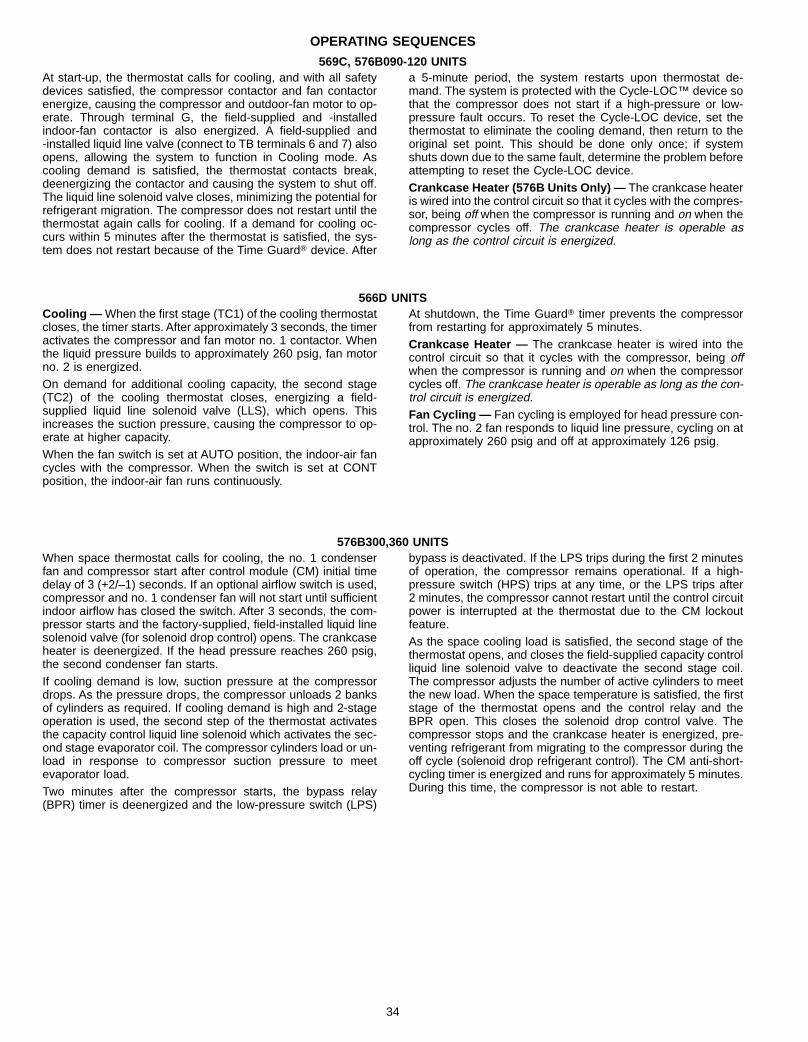
OPERATING SEQUENCES
569C, 576B090-120 UNITSAt start-up, the thermostat calls for cooling, and with all safetydevices satisfied, the compressor contactor and fan contactorenergize, causing the compressor and outdoor-fan motor to op-erate. Through terminal G, the field-supplied and -installedindoor-fan contactor is also energized. A field-supplied and-installed liquid line valve (connect to TB terminals 6 and 7) alsoopens, allowing the system to function in Cooling mode. Ascooling demand is satisfied, the thermostat contacts break,deenergizing the contactor and causing the system to shut off.The liquid line solenoid valve closes, minimizing the potential forrefrigerant migration. The compressor does not restart until thethermostat again calls for cooling. If a demand for cooling oc-curs within 5 minutes after the thermostat is satisfied, the sys-tem does not restart because of the Time GuardT device. After
a 5-minute period, the system restarts upon thermostat de-mand. The system is protected with the Cycle-LOC™ device sothat the compressor does not start if a high-pressure or low-pressure fault occurs. To reset the Cycle-LOC device, set thethermostat to eliminate the cooling demand, then return to theoriginal set point. This should be done only once; if systemshuts down due to the same fault, determine the problem beforeattempting to reset the Cycle-LOC device.Crankcase Heater (576B Units Only) — The crankcase heateris wired into the control circuit so that it cycles with the compres-sor, being off when the compressor is running and on when thecompressor cycles off. The crankcase heater is operable aslong as the control circuit is energized.
566D UNITSCooling — When the first stage (TC1) of the cooling thermostatcloses, the timer starts. After approximately 3 seconds, the timeractivates the compressor and fan motor no. 1 contactor. Whenthe liquid pressure builds to approximately 260 psig, fan motorno. 2 is energized.On demand for additional cooling capacity, the second stage(TC2) of the cooling thermostat closes, energizing a field-supplied liquid line solenoid valve (LLS), which opens. Thisincreases the suction pressure, causing the compressor to op-erate at higher capacity.When the fan switch is set at AUTO position, the indoor-air fancycles with the compressor. When the switch is set at CONTposition, the indoor-air fan runs continuously.
At shutdown, the Time GuardT timer prevents the compressorfrom restarting for approximately 5 minutes.Crankcase Heater — The crankcase heater is wired into thecontrol circuit so that it cycles with the compressor, being offwhen the compressor is running and on when the compressorcycles off. The crankcase heater is operable as long as the con-trol circuit is energized.Fan Cycling — Fan cycling is employed for head pressure con-trol. The no. 2 fan responds to liquid line pressure, cycling on atapproximately 260 psig and off at approximately 126 psig.
576B300,360 UNITSWhen space thermostat calls for cooling, the no. 1 condenserfan and compressor start after control module (CM) initial timedelay of 3 (+2/–1) seconds. If an optional airflow switch is used,compressor and no. 1 condenser fan will not start until sufficientindoor airflow has closed the switch. After 3 seconds, the com-pressor starts and the factory-supplied, field-installed liquid linesolenoid valve (for solenoid drop control) opens. The crankcaseheater is deenergized. If the head pressure reaches 260 psig,the second condenser fan starts.If cooling demand is low, suction pressure at the compressordrops. As the pressure drops, the compressor unloads 2 banksof cylinders as required. If cooling demand is high and 2-stageoperation is used, the second step of the thermostat activatesthe capacity control liquid line solenoid which activates the sec-ond stage evaporator coil. The compressor cylinders load or un-load in response to compressor suction pressure to meetevaporator load.Two minutes after the compressor starts, the bypass relay(BPR) timer is deenergized and the low-pressure switch (LPS)
bypass is deactivated. If the LPS trips during the first 2 minutesof operation, the compressor remains operational. If a high-pressure switch (HPS) trips at any time, or the LPS trips after2 minutes, the compressor cannot restart until the control circuitpower is interrupted at the thermostat due to the CM lockoutfeature.As the space cooling load is satisfied, the second stage of thethermostat opens, and closes the field-supplied capacity controlliquid line solenoid valve to deactivate the second stage coil.The compressor adjusts the number of active cylinders to meetthe new load. When the space temperature is satisfied, the firststage of the thermostat opens and the control relay and theBPR open. This closes the solenoid drop control valve. Thecompressor stops and the crankcase heater is energized, pre-venting refrigerant from migrating to the compressor during theoff cycle (solenoid drop refrigerant control). The CM anti-short-cycling timer is energized and runs for approximately 5 minutes.During this time, the compressor is not able to restart.
34

TYPICAL FIELD WIRING
AHA — Adjustable Heat AnticipatorC — Contactor, CompressorCB — Circuit BreakerCC — Cooling CompensatorCLO — Compressor LockoutHPS — High-Pressure SwitchIFC — Indoor-Fan ContactorLLSV — Liquid Line Solenoid ValveLPS — Low-Pressure SwitchTB — Terminal BlockTC — Thermostat-CoolingTDR — Time-Delay RelayTH — Thermostat-HeatingTRAN — Transformer
Terminal (Marked)
Terminal (Unmarked)
Terminal Block
Splice
Factory WiringAccessory or Optional WiringTo indicate common potential only,not to represent wiring.Field Wiring
LEGEND
569C Units
35

TYPICAL FIELD WIRING (cont)
AHA — Adjustable Heat AnticipatorC — Contactor, CompressorCB — Circuit BreakerCC — Cooling CompensatorCLO — Compressor LockoutHPS — High-Pressure SwitchIFC — Indoor-Fan ContactorLLSV — Liquid Line Solenoid ValveLPS — Low-Pressure SwitchTB — Terminal BlockTC — Thermostat-CoolingTDR — Time-Delay RelayTH — Thermostat-HeatingTRAN — Transformer
Terminal (Marked)
Terminal (Unmarked)
Terminal Block
Splice
Factory WiringAccessory or Optional WiringTo indicate common potential only,not to represent wiring.Field Wiring
LEGEND
576B090-120 Units
36

TYPICAL FIELD WIRING (cont)
LEGENDC — Compressor ContactorHD — Heating DeviceHT. ANT — Heat AnticipatorIFC — Indoor Fan ContactorLLSV — Liquid Line Solenoid ValveR — RelayTC — Thermostat, CoolingTH — Thermostat, Heating
Factory WiringField Wiring
NOTES:1. Combination LLSV plus IFC VA should
not exceed 30 VA.2. Do not exceed 5 VA (24 VAC) per coil. } Use accessory relay-transformer
package 319702-401 if these VAvalues must be exceeded.
566D Units
37
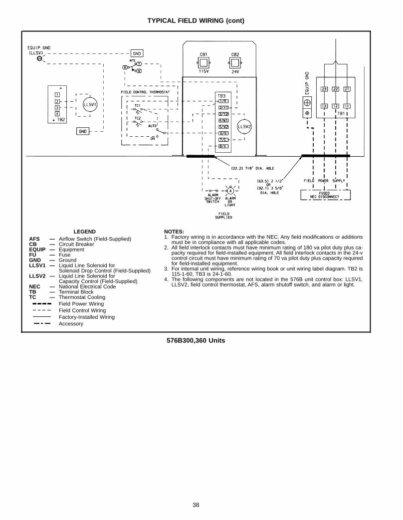
TYPICAL FIELD WIRING (cont)
LEGENDAFS — Airflow Switch (Field-Supplied)CB — Circuit BreakerEQUIP — EquipmentFU — FuseGND — GroundLLSV1 — Liquid Line Solenoid for
Solenoid Drop Control (Field-Supplied)LLSV2 — Liquid Line Solenoid for
Capacity Control (Field-Supplied)NEC — National Electrical CodeTB — Terminal BlockTC — Thermostat Cooling
Field Power WiringField Control WiringFactory-Installed WiringAccessory
NOTES:1. Factory wiring is in accordance with the NEC. Any field modifications or additions
must be in compliance with all applicable codes.2. All field interlock contacts must have minimum rating of 180 va pilot duty plus ca-
pacity required for field-installed equipment. All field interlock contacts in the 24-vcontrol circuit must have minimum rating of 70 va pilot duty plus capacity requiredfor field-installed equipment.
3. For internal unit wiring, reference wiring book or unit wiring label diagram. TB2 is115-1-60, TB3 is 24-1-60.
4. The following components are not located in the 576B unit control box: LLSV1,LLSV2, field control thermostat, AFS, alarm shutoff switch, and alarm or light.
576B300,360 Units
38

TYPICAL INSTALLATIONS
LEGENDNEC — National Electrical CodeTXV — Thermostatic Expansion Valve
Airflow
24-Volt WiringLine VoltagePiping
*Accessory item.†Field supplied.
NOTES:1. All piping must follow standard refrigerant piping techniques.2. All wiring must comply with the applicable local and national
codes.3. Wiring and piping shown are general points-of-connection guides
only and are not intended for, or include all details for, a specificinstallation.
4. Liquid line solenoid valve (solenoid drop control) is recom-mended to prevent refrigerant migration to the compressor.
5. Internal factory-supplied TXVs not shown.
Rooftop Installation — 569C, 576B090-120 Units
39

TYPICAL INSTALLATIONS (cont)
LEGENDNEC — National Electrical CodeTXV — Thermostatic Expansion Valve
Piping
*Field supplied.†Double riser may be required. Consult Applica-tion section for details.
NOTES:1. All piping must follow standard refrigerant piping techniques.2. All wiring must comply with the applicable local and national codes.3. Wiring and piping shown are general points-of-connection guides only and
are not intended for, or to include all details for, a specific installation.4. Liquid line solenoid valve (solenoid drop control) is recommended to pre-
vent refrigerant migration to the compressor.5. Internal factory-supplied TXVs not shown.
Rooftop Installation — 566D Units
40

TYPICAL INSTALLATIONS (cont)
LEGENDTXV — Thermostatic Expansion Valve
Piping*Field supplied.
NOTES:1. All piping must follow standard refrigerant piping techniques.2. All wiring must comply with the applicable local and national codes.3. Wiring and piping shown are general points-of-connection guides only and are
not intended for, or to include all details for, a specific installation.4. Liquid line solenoid valve (solenoid drop control) is recommended to prevent
refrigerant migration to the compressor.5. Internal factory-supplied TXVs not shown.
Ground-Level Installation — 566D Units
41

TYPICAL INSTALLATIONS (cont)
LEGENDNEC — National Electrical CodeTXV — Thermostatic Expansion Valve
Piping
*Field supplied.†Double riser may be required. Consult Applica-tion section for details.
Rooftop Installation — 576B300,360 Units
NOTES:1. All piping must follow standard refrigerant piping techniques.2. All wiring must comply with the applicable local and national codes.3. Wiring and piping shown are general points-of-connection guides only and
are not intended for, or to include all details for, a specific installation.4. Liquid line solenoid valve (solenoid drop control) is recommended to pre-
vent refrigerant migration to the compressor.5. Internal factory-supplied TXVs not shown.
42
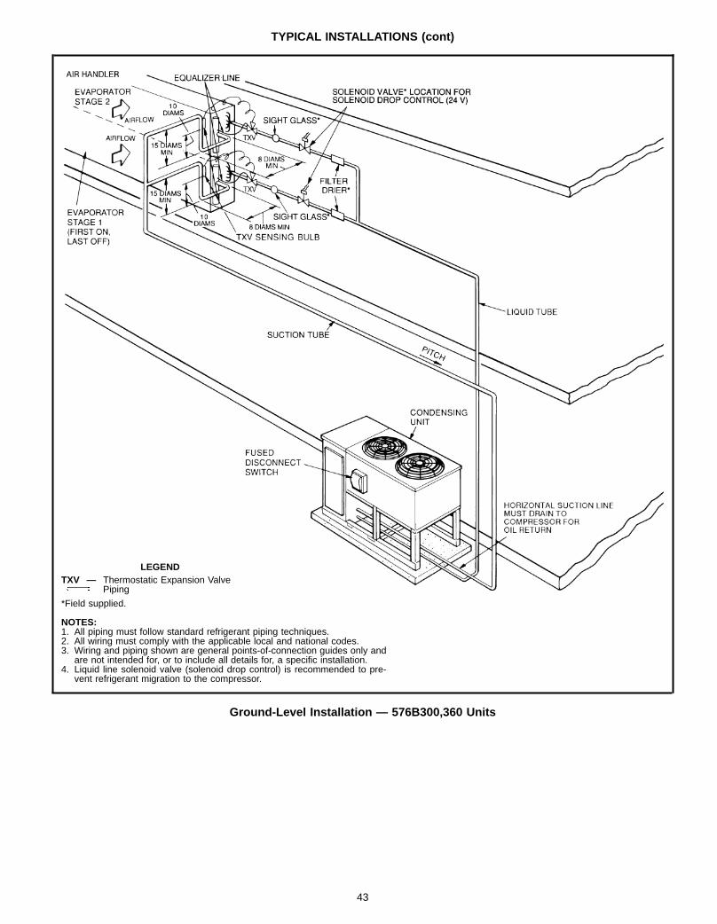
TYPICAL INSTALLATIONS (cont)
LEGENDTXV — Thermostatic Expansion Valve
Piping
*Field supplied.
NOTES:1. All piping must follow standard refrigerant piping techniques.2. All wiring must comply with the applicable local and national codes.3. Wiring and piping shown are general points-of-connection guides only and
are not intended for, or to include all details for, a specific installation.4. Liquid line solenoid valve (solenoid drop control) is recommended to pre-
vent refrigerant migration to the compressor.
Ground-Level Installation — 576B300,360 Units
43

APPLICATION DATA — 569C, 576B090-120 UNITS
1. Select air handler at no less than 300 cfm/ton (nominal con-densing unit capacity).
2. Total combined draw of the field-supplied liquid line solenoidvalve and air handler fan contactor must not exceed 22 va. Ifthe specified va must be exceeded, use a remote relay tocontrol the load.
OPERATING LIMITS
Maximum Cooling Load 115 FMinimum Return-Air Temperature 55 FMaximum Return-Air Temperature 95 FRange of Acceptable SaturationSuction Temperature 25 to 55 F
Maximum Discharge Temperature 275 FMinimum Discharge Superheat 60 F
LIQUID LINE DATA
UNITMAX
ALLOWABLELIQUID LIFT (ft)
LIQUID LINEMax AllowablePressure Drop
(psi)
Max AllowableTemp Loss
(F)569C072 86
7 2
569C090 60569C120 70576B090 60576B102 65576B120 65
NOTE: Values shown are for units operating at 45 F saturated suctionand 95 F entering air.
MINIMUM OUTDOOR-AIROPERATING TEMPERATURE
UNIT COMPRESSORCAPACITY
CONDENSERTEMP (F)
MINIMUMOUTDOORTEMP (F)
Standard
WithLow-
AmbientKit
569C072 100% 90 53 −20569C090 100% 90 60 −20569C120 100% 90 52 −20576B090 100% 90 60 −20576B102 100% 90 53 −20
576B120* 100%67%
9080
4852
−20−20
*Unit has one step of unloading.
NOTES:1. Field-fabricated wind baffles are required for low-ambient operation.2. For winter operation, use accessory winter start package.
REFRIGERANT PIPING SIZES
UNIT
LINEAR LENGTH OF PIPING — FT0-25 25-50 50-75 75-100
Line Size (in. OD)L S L S L S L S
569C072 1⁄2 11⁄8 1⁄2 11⁄8 1⁄2 11⁄8 1⁄2 11⁄8569C090 1⁄2 11⁄8 1⁄2 11⁄8 5⁄8 11⁄8 5⁄8 13⁄8569C120 5⁄8 11⁄8 5⁄8 13⁄8 5⁄8 13⁄8 5⁄8 13⁄8576B090 1⁄2 11⁄8 1⁄2 11⁄8 5⁄8 11⁄8 5⁄8 13⁄8576B102 5⁄8 11⁄8 5⁄8 11⁄8 5⁄8 13⁄8 5⁄8 13⁄8576B120 5⁄8 11⁄8 5⁄8 11⁄8 5⁄8 13⁄8 5⁄8 13⁄8
LEGENDL — Liquid Line S — Suction Line
NOTES:1. Pipe sizes are based on a 2° F loss for liquid and suction lines.2. Pipe sizes are based on the maximum linear length, shown for each
column, plus a 50% allowance for fittings.3. Charge units with R-22 in accordance with unit installation
instructions.
44

APPLICATION DATA — 566D UNITS
1. Select equipment to match or to be slightly less than peakload. This provides better humidity control, less unit cycling,and less part-load operation.
2. When selecting vapor line sizes, oil return must be evalu-ated, particularly at part-load conditions.
3. The indoor fan must always be operating when outdoor unitis operating.
4. Ductwork should be sized according to unit size, notbuilding load.
5. To minimize the possibility of air recirculation, avoid the useof concentric supply/return grilles.
6. Indoor equipment should be selected at no less than300 cfm/ton.
7. A liquid line solenoid valve is recommended for all installa-tions and is required if the interconnecting piping exceeds75 feet.Field-supplied liquid line solenoid valves (capacity control)may be used to deactivate upper portion of evaporator coilsurface in order to unload compressor (suction-activated un-loaders) at part-load conditions.
OPERATING LIMITS
Maximum Outdoor Ambient 115 FMinimum Outdoor Ambient See Minimum Outdoor-Air
Operating Temperaturetable below.
Minimum Return-Air Temperature 55 FMaximum Return-Air Temperature 95 FNormal Acceptable SaturationSuction Temperature Range 25 to 55 F
Maximum Discharge Temperature 295 FMinimum Discharge Superheat 60 F
MINIMUM OUTDOOR-AIROPERATING TEMPERATURE
UNIT566D
NO. OFCYL
% FULLLOAD CAP.
MINIMUM OUTDOOROPER TEMP (F)*DX Evaporator(s)
1206 100 354 67 552† 33 75
1506 100 374 67 582† 33 77
1806 100 234 67 462† 33 70
2404 100 152 50 31
LEGENDCAP. — CapacityCYL — CylindersDX — Direct Expansion
*With accessory low-ambient kit, units can operate to –20 F ambient.†Requires accessory pressure-operated unloader package.
NOTES:1. Minimum outdoor-air operating temperatures for single direct-
expansion evaporator based on:
MIN. COND TEMP 90 F 80 F 70 F% COMPR CAP. 100-75 75-50 50-17
2. For low-ambient operation, field-fabricated wind baffles are requiredon all 566D units.
3. For winter operation, use accessory winter-start package.
LIQUID LINE DATA
UNIT566D
MAX.ALLOW.
LIQUID LIFT(ft)
LIQUID LINEMax Allow.Press. Drop
(psi)
Max Allow.Temp Loss
(F)120 52
7 2150 67180 82240 87
NOTE: Data above is for units operating at 45 F saturated suction and95 F entering air.
LEGENDTXV — Thermostatic Expansion Valve
Location of One Liquid Line Solenoid ValveServicing 2 Coil Circuits (Solenoid Drop Control)
LEGENDTXV — Thermostatic Expansion Valve
Face-Split Coil Suction and Liquid Line Piping
45
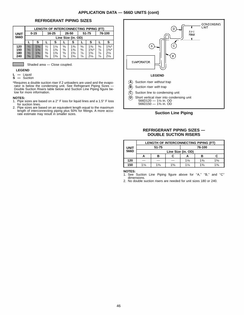
APPLICATION DATA — 566D UNITS (cont)
REFRIGERANT PIPING SIZES
UNIT566D
LENGTH OF INTERCONNECTING PIPING (FT)0-15 16-25 26-50 51-75 76-100
Line Size (in. OD)L S L S L S L S L S
120 1⁄2 11⁄8 1⁄2 11⁄8 5⁄8 13⁄8 5⁄8 13⁄8 5⁄8 15⁄8*150 1⁄2 11⁄8 1⁄2 13⁄8 5⁄8 13⁄8 5⁄8 15⁄8* 7⁄8 15⁄8*180 1⁄2 13⁄8 5⁄8 13⁄8 5⁄8 15⁄8 7⁄8 15⁄8 7⁄8 21⁄8240 5⁄8 15⁄8 5⁄8 15⁄8 7⁄8 15⁄8 7⁄8 21⁄8 7⁄8 21⁄8
Shaded area — Close coupled.
LEGENDL — LiquidS — Suction
*Requires a double suction riser if 2 unloaders are used and the evapo-rator is below the condensing unit. See Refrigerant Piping Sizes —Double Suction Risers table below and Suction Line Piping figure be-low for more information.
NOTES:1. Pipe sizes are based on a 2° F loss for liquid lines and a 1.5° F loss
for suction lines.2. Pipe sizes are based on an equivalent length equal to the maximum
length of interconnecting piping plus 50% for fittings. A more accu-rate estimate may result in smaller sizes.
REFRIGERANT PIPING SIZES —DOUBLE SUCTION RISERS
UNIT566D
LENGTH OF INTERCONNECTING PIPING (FT)51-75 76-100
Line Size (in. OD)A B C A B C
120 — — — 11⁄8 13⁄8 15⁄8150 11⁄8 13⁄8 15⁄8 11⁄8 13⁄8 13⁄8
NOTES:1. See Suction Line Piping figure above for ‘‘A,’’ ‘‘B,’’ and ‘‘C’’
dimensions.2. No double suction risers are needed for unit sizes 180 or 240.
LEGEND
A Suction riser without trap
B Suction riser with trap
C Suction line to condensing unit
D Short vertical riser into condensing unit566D120 — 11⁄8 in. OD566D150 — 13⁄8 in. OD
Suction Line Piping
46

APPLICATION DATA — 576B300,360 UNITS
1. Select equipment to match or to be slightly less than peakload. This provides better humidity control, less unit cycling,and less part-load operation.
2. When selecting vapor line sizes, oil return should be evalu-ated, particularly at part-load conditions.
3. The indoor fan must always be operating when outdoor fan isoperating.
4. Unit cycles should be limited to 3 or less per hour.
5. Multiple outdoor units may be used with a single indoor unit;this involves multiple refrigeration circuits.
IMPORTANT: When application is in a variable air volume (VAV)system, total building load is not the sum of the individual peakloads. If individual peak loads are summed, the equipmenttends to be oversized for the load.6. To minimize return-air temperature extremes, use the equip-
ment room as a return-air plenum when applying VAV sys-tems with supply-to-return-air recycle.
7. Indoor equipment should be selected at no less than300 cfm/ton.
OPERATING LIMITS
Maximum Cooling Load 115 FMinimum Cooling Load Additional head pressure
control may be required below35 F outdoor ambient.
Minimum Return-Air Temperature 55 FMaximum Return-Air Temperature 95 FNormal Acceptable SaturationSuction Temperature Range 30 to 55 F
Maximum Discharge Temperature 295 FMinimum Discharge Superheat 60 F
MINIMUM OUTDOOR-AIR OPERATINGTEMPERATURE (F)
UNIT576B
COMPRCAP. (%)
CONDTEMP (F)
MIN OUTDOOR TEMPStandard
UnitLow Ambient
Control
300100 90 31 –2067 80 35 –2033 70 43 –20
360100 90 30 –2067 80 34 –2033 70 42 –20
MAXIMUM LIQUID LIFT*
UNIT 576B FT300 76360 67
*Based on 2° F liquid line loss and 7 psi pressureloss for accessories.
REFRIGERANT PIPING SIZES
SINGLE SUCTION RISERS
UNIT576B
LENGTH OF INTERCONNECTING PIPING, FT16-25 26-50 51-75 76-100 101-200
L S L S L S L S L S300 7⁄8 15⁄8 7⁄8 21⁄8* 7⁄8 21⁄8* 7⁄8 21⁄8* 7⁄8 21⁄8*360 7⁄8 21⁄8 7⁄8 21⁄8 7⁄8 21⁄8 11⁄8 21⁄8 11⁄8 25⁄8*
LEGENDL — Liquid LineS — Suction Line
*IMPORTANT: — Requires a double suction riser if evaporator is belowcondensing unit. See table below.NOTE: Liquid and suction line sizes are OD (in.).
DOUBLE SUCTION RISERS
UNIT576B
LENGTH OF INTERCONNECTING PIPING, FT26-50 51-75 76-100 101-200
A B C A B C A B C A B C300 13⁄8 15⁄8 21⁄8 13⁄8 15⁄8 21⁄8 13⁄8 15⁄8 21⁄8 13⁄8 15⁄8 21⁄8360 — — — — — — — — — 15⁄8 21⁄8 25⁄8
NOTE: A, B, and C dimensions relate to reference diagram above.
LEGEND
A Suction riser without trap
B Suction riser with trap
C Horizontal suction line tocondensing unit
D Short vertical riser576B300 — 15⁄8 in. OD576B360 — 21⁄8 in. OD
Suction Line Piping
47

APPLICATION DATA — 524A UNITS1. Select equipment to match or to be slightly less than peak
load. This provides better humidity control, less unit cycling,and less part-load operation. Equipment should be selectedto perform at no less than 300 cfm/ton.
2. The air handler fan must always be operating when the con-densing unit is operating.
3. Ductwork should be sized according to unit size, not buildingload. For larger units with two fans, a split duct transition isrecommended at the fan outlets, but a plenum can be usedwith slight reduction in external static pressure capability.
4. For VAV systems with supply-to-return air recycling, use theequipment room as a return air plenum.
OPERATING LIMITS
Maximum fan speed524A072-240 1200 rpm
Maximum fan speed524A300,360 1100 rpm
FACTORY-INSTALLED NOZZLE AND DISTRIBUTOR DATA
UNIT TXVQty...Part No.
DISTRIBUTORQty...Part No.
FEEDER TUBESPER DISTRIBUTOR
Qty...Size (in.)
NOZZLEQty...Part No.
524A072 1...XVE-5 1...1116 12...1⁄4 1...E5524A090 1...SVE-8 1...1126 15...1⁄4 1...C6524A120 2...XVE-4 2...1115 9...1⁄4 2...E4524A150 2...XVE-5 2...1115 9...1⁄4 2...E5524A180 2...XVE-8 2...1116 12...1⁄4 2...E6524A240 2...XVE-10 2...1116 13...1⁄4 2...E8524A300 2...EBSVE-11 2...1126 15...1⁄4 2...C10524A360 2...SVE-15 2...1126 18...1⁄4 2...C12
TXV — Thermostatic Expansion Valve
NOTE: Hot gas bypass applications require field-supplied auxiliary side connector.
STANDARD FAN MOTOR DATA230-1-60 MOTORS
UNIT524A 072 090
Speed (rpm) 1725 1725Hp 1.3 2.4Frame (NEMA) 56Y 56YShaft Dia (in.) 5⁄8 5⁄8
NEMA — National Electrical Manufacturers Association
208/230-3-60 AND 460-3-60 MOTORS
UNIT524A 072 090 120 150 180 240 300 360
Speed (rpm) 1725 1725 1725 1725 1725 1745 1745 1745Hp 1.7 2.4 2.4 2.9 3.7 5.0 7.5 10.0Frame (NEMA) 56Y 56Y 56Y 56Y 56Y S184T S213T S215TShaft Dia (in.) 5⁄8 5⁄8 5⁄8 7⁄8 7⁄8 11⁄8 13⁄8 13⁄8
NEMA — National Electrical Manufacturers Association
575-3-60 MOTORS
UNIT524A 072 090 120 150 180 240 300 360
Speed (rpm) 1725 1725 1725 1725 1725 1745 1755 1755Hp 1.0 2.0 2.0 3.0 3.0 5.0 7.5 10.0Frame (NEMA) 56 56HZ 56HZ 56HZ 56HZ 184T S213T S215TShaft Dia (in.) 5⁄8 7⁄8 7⁄8 7⁄8 7⁄8 11⁄8 13⁄8 13⁄8
NEMA — National Electrical Manufacturers Association
48
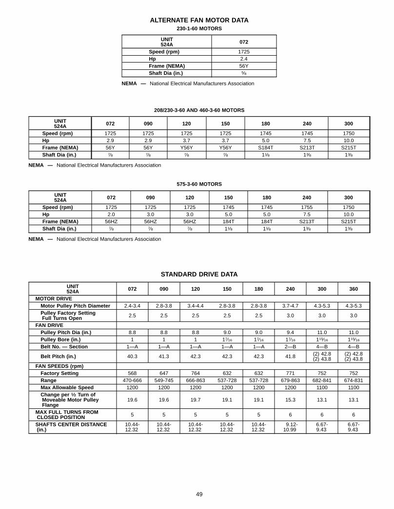
ALTERNATE FAN MOTOR DATA230-1-60 MOTORS
UNIT524A 072
Speed (rpm) 1725Hp 2.4Frame (NEMA) 56YShaft Dia (in.) 5⁄8
NEMA — National Electrical Manufacturers Association
208/230-3-60 AND 460-3-60 MOTORS
UNIT524A 072 090 120 150 180 240 300
Speed (rpm) 1725 1725 1725 1725 1745 1745 1750Hp 2.9 2.9 3.7 3.7 5.0 7.5 10.0Frame (NEMA) 56Y 56Y Y56Y Y56Y S184T S213T S215TShaft Dia (in.) 7⁄8 7⁄8 7⁄8 7⁄8 11⁄8 13⁄8 13⁄8
NEMA — National Electrical Manufacturers Association
575-3-60 MOTORS
UNIT524A 072 090 120 150 180 240 300
Speed (rpm) 1725 1725 1725 1745 1745 1755 1750Hp 2.0 3.0 3.0 5.0 5.0 7.5 10.0Frame (NEMA) 56HZ 56HZ 56HZ 184T 184T S213T S215TShaft Dia (in.) 7⁄8 7⁄8 7⁄8 11⁄8 11⁄8 13⁄8 13⁄8
NEMA — National Electrical Manufacturers Association
STANDARD DRIVE DATA
UNIT524A 072 090 120 150 180 240 300 360
MOTOR DRIVEMotor Pulley Pitch Diameter 2.4-3.4 2.8-3.8 3.4-4.4 2.8-3.8 2.8-3.8 3.7-4.7 4.3-5.3 4.3-5.3Pulley Factory SettingFull Turns Open 2.5 2.5 2.5 2.5 2.5 3.0 3.0 3.0
FAN DRIVEPulley Pitch Dia (in.) 8.8 8.8 8.8 9.0 9.0 9.4 11.0 11.0Pulley Bore (in.) 1 1 1 17⁄16 17⁄16 17⁄16 115⁄16 115⁄16Belt No. — Section 1—A 1—A 1—A 1—A 1—A 2—B 4—B 4—B
Belt Pitch (in.) 40.3 41.3 42.3 42.3 42.3 41.8 (2) 42.8(2) 43.8
(2) 42.8(2) 43.8
FAN SPEEDS (rpm)Factory Setting 568 647 764 632 632 771 752 752Range 470-666 549-745 666-863 537-728 537-728 679-863 682-841 674-831Max Allowable Speed 1200 1200 1200 1200 1200 1200 1100 1100Change per 1⁄2 Turn ofMoveable Motor PulleyFlange
19.6 19.6 19.7 19.1 19.1 15.3 13.1 13.1
MAX FULL TURNS FROMCLOSED POSITION 5 5 5 5 5 6 6 6
SHAFTS CENTER DISTANCE(in.)
10.44-12.32
10.44-12.32
10.44-12.32
10.44-12.32
10.44-12.32
9.12-10.99
6.67-9.43
6.67-9.43
49
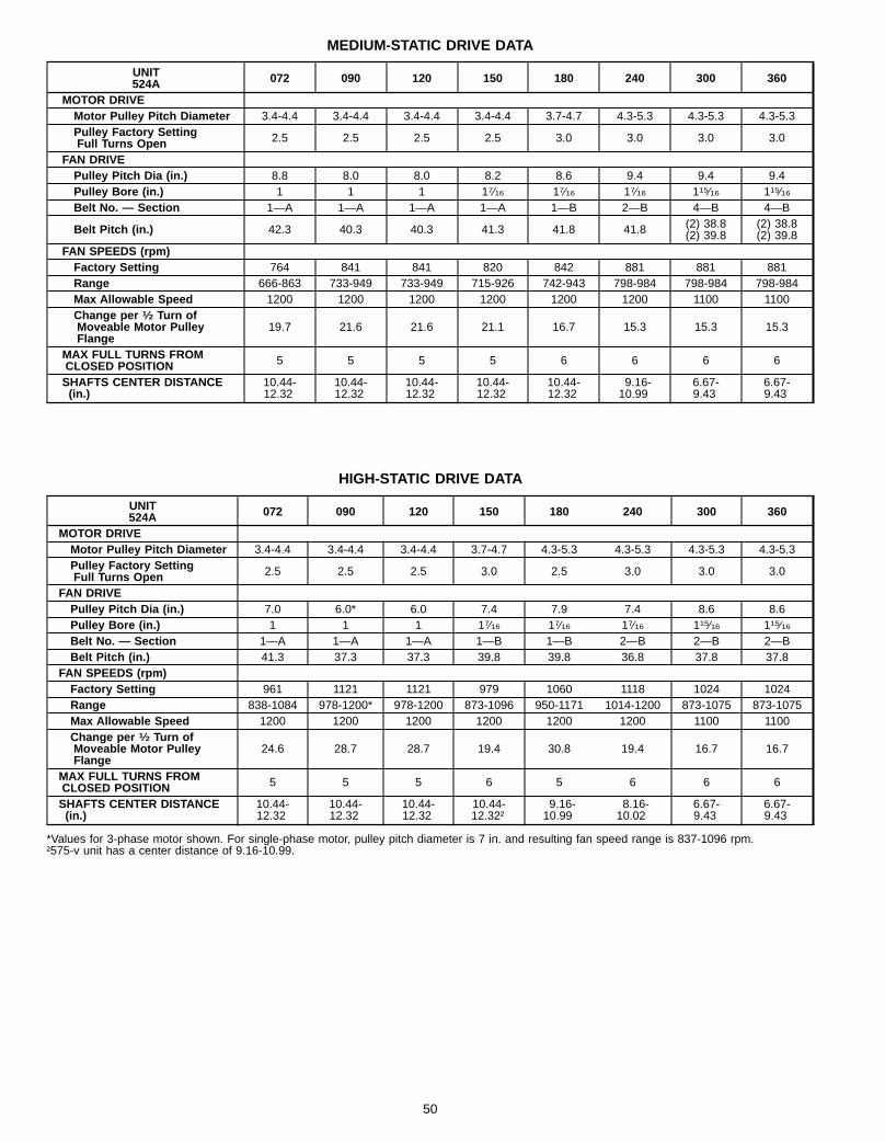
MEDIUM-STATIC DRIVE DATA
UNIT524A 072 090 120 150 180 240 300 360
MOTOR DRIVEMotor Pulley Pitch Diameter 3.4-4.4 3.4-4.4 3.4-4.4 3.4-4.4 3.7-4.7 4.3-5.3 4.3-5.3 4.3-5.3Pulley Factory SettingFull Turns Open 2.5 2.5 2.5 2.5 3.0 3.0 3.0 3.0
FAN DRIVEPulley Pitch Dia (in.) 8.8 8.0 8.0 8.2 8.6 9.4 9.4 9.4Pulley Bore (in.) 1 1 1 17⁄16 17⁄16 17⁄16 115⁄16 115⁄16Belt No. — Section 1—A 1—A 1—A 1—A 1—B 2—B 4—B 4—B
Belt Pitch (in.) 42.3 40.3 40.3 41.3 41.8 41.8 (2) 38.8(2) 39.8
(2) 38.8(2) 39.8
FAN SPEEDS (rpm)Factory Setting 764 841 841 820 842 881 881 881Range 666-863 733-949 733-949 715-926 742-943 798-984 798-984 798-984Max Allowable Speed 1200 1200 1200 1200 1200 1200 1100 1100Change per 1⁄2 Turn ofMoveable Motor PulleyFlange
19.7 21.6 21.6 21.1 16.7 15.3 15.3 15.3
MAX FULL TURNS FROMCLOSED POSITION 5 5 5 5 6 6 6 6
SHAFTS CENTER DISTANCE(in.)
10.44-12.32
10.44-12.32
10.44-12.32
10.44-12.32
10.44-12.32
9.16-10.99
6.67-9.43
6.67-9.43
HIGH-STATIC DRIVE DATA
UNIT524A 072 090 120 150 180 240 300 360
MOTOR DRIVEMotor Pulley Pitch Diameter 3.4-4.4 3.4-4.4 3.4-4.4 3.7-4.7 4.3-5.3 4.3-5.3 4.3-5.3 4.3-5.3Pulley Factory SettingFull Turns Open 2.5 2.5 2.5 3.0 2.5 3.0 3.0 3.0
FAN DRIVEPulley Pitch Dia (in.) 7.0 6.0* 6.0 7.4 7.9 7.4 8.6 8.6Pulley Bore (in.) 1 1 1 17⁄16 17⁄16 17⁄16 115⁄16 115⁄16Belt No. — Section 1—A 1—A 1—A 1—B 1—B 2—B 2—B 2—BBelt Pitch (in.) 41.3 37.3 37.3 39.8 39.8 36.8 37.8 37.8
FAN SPEEDS (rpm)Factory Setting 961 1121 1121 979 1060 1118 1024 1024Range 838-1084 978-1200* 978-1200 873-1096 950-1171 1014-1200 873-1075 873-1075Max Allowable Speed 1200 1200 1200 1200 1200 1200 1100 1100Change per 1⁄2 Turn ofMoveable Motor PulleyFlange
24.6 28.7 28.7 19.4 30.8 19.4 16.7 16.7
MAX FULL TURNS FROMCLOSED POSITION 5 5 5 6 5 6 6 6
SHAFTS CENTER DISTANCE(in.)
10.44-12.32
10.44-12.32
10.44-12.32
10.44-12.32†
9.16-10.99
8.16-10.02
6.67-9.43
6.67-9.43
*Values for 3-phase motor shown. For single-phase motor, pulley pitch diameter is 7 in. and resulting fan speed range is 837-1096 rpm.†575-v unit has a center distance of 9.16-10.99.
50

ENGINEER’S SPECIFICATION GUIDE — 569C, 576B090-120 UNITS
GENERAL: Furnish and install outdoor-mounted, single-piece,air-cooled condensing unit suitable for on-the-ground or rooftopinstallation.Unit shall consist of a reciprocating compressor, an air-cooledcoil, propeller-type condenser fan, and a control box.Unit shall discharge supply air upward as shown on contractdrawings.Unit shall be used in a refrigeration circuit matched with a pack-aged fan coil unit.Contained within the unit enclosure shall be all factory wiring,piping, controls, compressor, and special features required priorto field start-up.Units shall operate on 3-phase, 60-cycle power at the voltageshown on the unit informative plate.Unit control circuit shall contain a 24-v transformer for unitcontrol.COOLING CAPACITY: Total cooling capacity of the unit shall be
Btuh or greater, with air-entering condenser at F,and a saturated suction temperature at compressor of F.Saturated condensing temperature shall not exceed F.Maximum liquid lift shall be feet.CABINET: Unit cabinet shall be constructed of galvanized steel,bonderized, and coated with a prepainted baked enamel finish.Lifting holes shall be provided to facilitate rigging.DIMENSIONS: Dimensions of entire assembly shall not bemore than in. high and in. wide.
CONNECTIONS: Only one liquid line, one suction line, and onepower supply connection shall be required for each unit.The electrical power shall be single-point connection.FAN SECTION: Condenser fans shall be direct driven,propeller-type, discharging air vertically upward.Fan blades shall be balanced and fan discharge openings shallbe equipped with PVC-coated steel wire safety guards.Condenser fan and motor shall be corrosion-resistant.Fan motor bearings shall be permanently lubricated.COIL SECTION: The condenser coil shall be air-cooled and cir-cuited for integral subcooler.
Coil shall be constructed of aluminum fins (copper fins optional)mechanically bonded to internally grooved seamless coppertubes which are then cleaned, dehydrated, and sealed.COMPRESSOR: The compressor shall be semi-hermetic(576B) or hermetic (569C) reciprocating type, and shall bemounted on vibration isolators. Units with semi-hermetic com-pressors shall have an integral crankcase heater.Semi-hermetic compressor (576B) shall have automatically re-versible positive-displacement oil pump to protect compressor;casing with discharge shutoff valves, oil level control orifice, andoil-pressure regulating valve; unloader (576B120) for capacityreduction capability.REFRIGERATION COMPONENTS: Refrigeration circuit com-ponents shall include liquid line service valve, suction line ser-vice valve, liquid filter drier, a full charge of compressor oil, anda holding charge of refrigerant.CONTROLS: Minimum control functions shall include powerand control terminal blocks; 5-minute recycle protection to pre-vent compressor short-cycling; and lockout on auto-reset safetyuntil reset from thermostat.Minimum safety devices are equipped with automatic reset (af-ter resetting first at thermostat) and shall include high dischargepressure cutout and low suction pressure cutout.APPROVALS: Unit shall be rated in accordance with ARIStandard 210/240 (latest edition). Construction shall complywith ASHRAE 15 latest revision safety code and comply withNEC.Unit shall be constructed in accordance with UL 1995 standardand shall carry the UL label of approval. Unit shall have CSAapproval.Unit cabinet shall be capable of withstanding Federal TestMethod Standard No. 141 (method 6061) 500-hour salt spraytest.Unit shall be manufactured in a facility registered to theISO 9002 manufacturing quality standard.Air-cooled condenser coils for hermetic compressor units shallbe leak tested at 200 psig and pressure tested at 428 psig.ACCESSORIES: Field-installed accessories shall include lowambient temperature kit, gage panel, winter-start relay package,condenser coil guard assembly, condenser coil hail guard as-sembly, thermostats, and subbases. Electric solenoid unloaderconversion package shall be available for 576B120 unit only.
51

ENGINEER’S SPECIFICATION GUIDE — 566D UNITS
GENERAL: Furnish and install an air-cooled condensing unit.The unit shall be properly assembled and tested at the factory,and shall be designed for use with R-22.Nominal unit electrical characteristics shall be v, 3 ph,60 Hz. The unit shall be capable of satisfactory operation withinvoltage limits of v to v.The unit shall operate down to F outdoor-air temperatureentering condenser with standard controls and down to
F outdoor-air temperature entering condenser with ad-dition of accessory low-ambient kit.COOLING CAPACITY: Total cooling capacity of the unit shall be
Btuh or greater, with air entering condenser atF, and a saturated suction temperature at compressor ofF. Saturated condensing temperature shall not exceedF. Maximum liquid lift shall be ft.
CABINET: Unit cabinet shall be constructed of galvanized steelthat is zinc phosphatized and prepainted with baked enamel.Cabinet shall be capable of withstanding Federal Test methodStandard no. 141 (method 6061) 500-hour salt-spray test.Cabinet panels shall be easily removable for service access.Openings shall be provided for power and refrigerantconnections.DIMENSIONS: Dimensions of entire assembly shall not bemore than in. high and in. wide.
CONNECTIONS: Only one liquid line, one suction line, and onepower supply connection shall be required for each unit.FANS: Unit shall be equipped with two direct-driven, propeller-type fans in vertical discharge configuration.Condenser fan motors shall have inherent protection, and shallbe of the permanently lubricated type, resiliently mounted.Each fan shall be equipped with a safety guard.Controls shall be included for cycling fan(s) for intermediateseason operation.COIL SECTION: Condenser coil shall be of non-ferrous con-struction, with aluminum-plate fins mechanically bonded toseamless copper tubes.
Condenser coil shall be circuited for subcooling.COMPRESSOR: Unit shall have one compressor, of service-able semi-hermetic design with external spring isolators, andshall have an automatically reversible oil pump and crankcaseheater.Maximum power input to compressor(s) shall not exceedkW at conditions specified.Compressor(s) shall unload in response to suction pressuredown to % of full capacity in steps for partial loadoperation.CONTROLS: Unit controls shall be factory wired and located ina separate enclosure.Safety devices shall consist of low-pressure switch, high-pressure switch, and compressor overload devices.Unit wiring shall incorporate a positive-acting timer to preventshort cycling of compressor if power is interrupted. Time GuardTtimer shall prevent compressor from restarting for approxi-mately 5 minutes after shut-off.The units shall have transformer for 24-v control circuit for allvoltages.Circuit breaker shall provide phase protection.APPROVALS: Performance shall be rated in accordance withARI Standards 210/240 and 360 (latest editions). Condensingunit only performance shall be rated in accordance with ARIStandard 365 (latest edition).Unit shall be manufactured in a facility registered to theISO 9002 manufacturing quality standard.Unit shall be constructed in accordance with UL regulations andshall carry UL label of approval.ACCESSORIES: Field-installed accessories shall includepressure-operated unloader (sizes 120-180), gage panel, winterstart package, electric solenoid unloader conversion package,thermostat and subbase, coil guard, and low ambient kit.
52
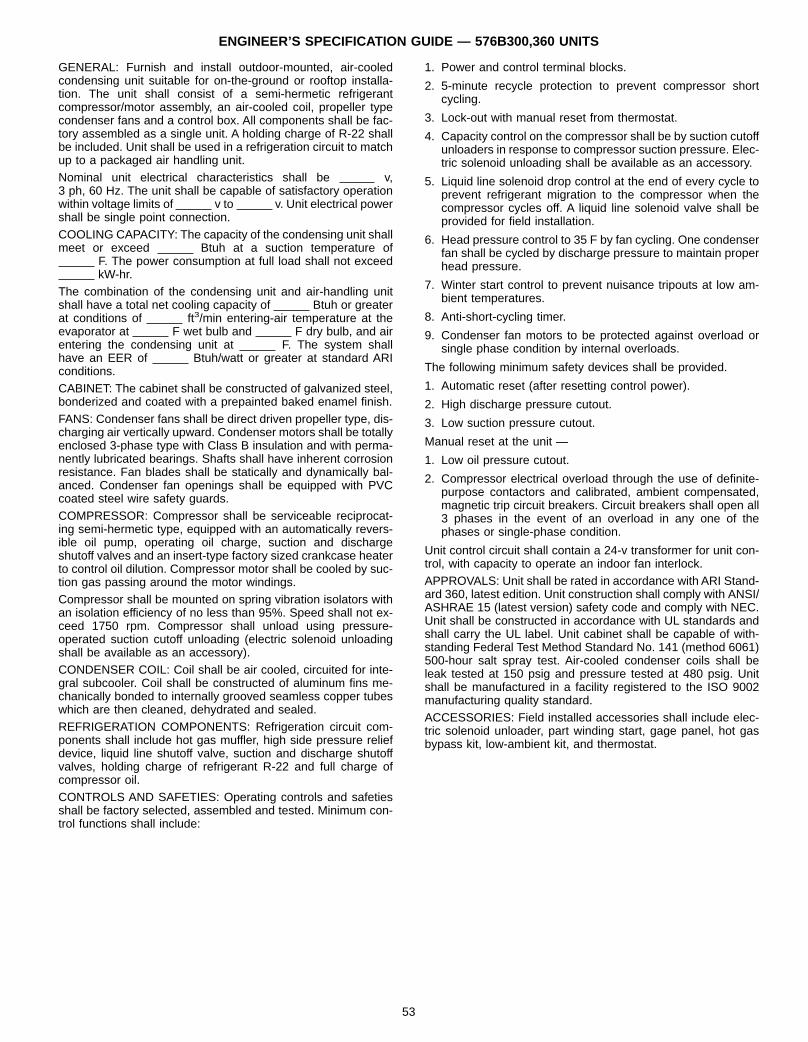
ENGINEER’S SPECIFICATION GUIDE — 576B300,360 UNITS
GENERAL: Furnish and install outdoor-mounted, air-cooledcondensing unit suitable for on-the-ground or rooftop installa-tion. The unit shall consist of a semi-hermetic refrigerantcompressor/motor assembly, an air-cooled coil, propeller typecondenser fans and a control box. All components shall be fac-tory assembled as a single unit. A holding charge of R-22 shallbe included. Unit shall be used in a refrigeration circuit to matchup to a packaged air handling unit.Nominal unit electrical characteristics shall be v,3 ph, 60 Hz. The unit shall be capable of satisfactory operationwithin voltage limits of v to v. Unit electrical powershall be single point connection.COOLING CAPACITY: The capacity of the condensing unit shallmeet or exceed Btuh at a suction temperature of
F. The power consumption at full load shall not exceedkW-hr.
The combination of the condensing unit and air-handling unitshall have a total net cooling capacity of Btuh or greaterat conditions of ft3/min entering-air temperature at theevaporator at F wet bulb and F dry bulb, and airentering the condensing unit at F. The system shallhave an EER of Btuh/watt or greater at standard ARIconditions.CABINET: The cabinet shall be constructed of galvanized steel,bonderized and coated with a prepainted baked enamel finish.FANS: Condenser fans shall be direct driven propeller type, dis-charging air vertically upward. Condenser motors shall be totallyenclosed 3-phase type with Class B insulation and with perma-nently lubricated bearings. Shafts shall have inherent corrosionresistance. Fan blades shall be statically and dynamically bal-anced. Condenser fan openings shall be equipped with PVCcoated steel wire safety guards.COMPRESSOR: Compressor shall be serviceable reciprocat-ing semi-hermetic type, equipped with an automatically revers-ible oil pump, operating oil charge, suction and dischargeshutoff valves and an insert-type factory sized crankcase heaterto control oil dilution. Compressor motor shall be cooled by suc-tion gas passing around the motor windings.Compressor shall be mounted on spring vibration isolators withan isolation efficiency of no less than 95%. Speed shall not ex-ceed 1750 rpm. Compressor shall unload using pressure-operated suction cutoff unloading (electric solenoid unloadingshall be available as an accessory).CONDENSER COIL: Coil shall be air cooled, circuited for inte-gral subcooler. Coil shall be constructed of aluminum fins me-chanically bonded to internally grooved seamless copper tubeswhich are then cleaned, dehydrated and sealed.REFRIGERATION COMPONENTS: Refrigeration circuit com-ponents shall include hot gas muffler, high side pressure reliefdevice, liquid line shutoff valve, suction and discharge shutoffvalves, holding charge of refrigerant R-22 and full charge ofcompressor oil.CONTROLS AND SAFETIES: Operating controls and safetiesshall be factory selected, assembled and tested. Minimum con-trol functions shall include:
1. Power and control terminal blocks.
2. 5-minute recycle protection to prevent compressor shortcycling.
3. Lock-out with manual reset from thermostat.
4. Capacity control on the compressor shall be by suction cutoffunloaders in response to compressor suction pressure. Elec-tric solenoid unloading shall be available as an accessory.
5. Liquid line solenoid drop control at the end of every cycle toprevent refrigerant migration to the compressor when thecompressor cycles off. A liquid line solenoid valve shall beprovided for field installation.
6. Head pressure control to 35 F by fan cycling. One condenserfan shall be cycled by discharge pressure to maintain properhead pressure.
7. Winter start control to prevent nuisance tripouts at low am-bient temperatures.
8. Anti-short-cycling timer.
9. Condenser fan motors to be protected against overload orsingle phase condition by internal overloads.
The following minimum safety devices shall be provided.
1. Automatic reset (after resetting control power).
2. High discharge pressure cutout.
3. Low suction pressure cutout.
Manual reset at the unit —
1. Low oil pressure cutout.
2. Compressor electrical overload through the use of definite-purpose contactors and calibrated, ambient compensated,magnetic trip circuit breakers. Circuit breakers shall open all3 phases in the event of an overload in any one of thephases or single-phase condition.
Unit control circuit shall contain a 24-v transformer for unit con-trol, with capacity to operate an indoor fan interlock.APPROVALS: Unit shall be rated in accordance with ARI Stand-ard 360, latest edition. Unit construction shall comply with ANSI/ASHRAE 15 (latest version) safety code and comply with NEC.Unit shall be constructed in accordance with UL standards andshall carry the UL label. Unit cabinet shall be capable of with-standing Federal Test Method Standard No. 141 (method 6061)500-hour salt spray test. Air-cooled condenser coils shall beleak tested at 150 psig and pressure tested at 480 psig. Unitshall be manufactured in a facility registered to the ISO 9002manufacturing quality standard.ACCESSORIES: Field installed accessories shall include elec-tric solenoid unloader, part winding start, gage panel, hot gasbypass kit, low-ambient kit, and thermostat.
53

ENGINEER’S SPECIFICATION GUIDE — 524A UNITSGENERAL: Furnish and install indoor, draw-thru, direct expan-sion, packaged air handling unit that can be used with or withoutductwork in a suspended horizontal configuration or free-standing vertical configuration. Unit shall not require modifica-tion for horizontal or vertical installation. Unit shall consist offorward-curved belt-driven centrifugal fan(s), motor and driveassembly, prewired fan motor contactor, factory-installed refrig-erant metering devices, direct-expansion coil, 2-in. disposableair filters, and condensate drain pans for vertical or horizontalconfigurations. Unit shall be capable of being used in a refrig-erant circuit with a matching air-cooled condensing unit(s).Nominal unit electrical characteristics shall be v,
ph, 60 Hz. The unit shall be capable of satisfactoryoperation within voltage limits of v to v.Unit shall be capable of providing a constant volume of air at aspecified external static pressure within the unit nominal oper-ating range.
CABINET: Unit cabinet shall be constructed of mill galvanizedsteel. Painted American Sterling Gray casing shall be availableas an option.Cabinet panels shall be fully insulated with a fire-retardant ma-terial. Insulation shall be cleanable and treated with EPA-approved antimicrobial agent.FAN SECTION: Unit shall be equipped with double-inlet fanwheel(s) with forward-curved blades that shall operate at least25% below the first critical speed, and shall be designed forcontinuous operation at maximum rated fan speed.Fan wheels and scrolls shall be constructed of mill galvanizedsteel. The fan shaft shall be constructed of steel, coated with ahydrocarbon rust inhibitor. Fan wheels shall be statically and dy-namically balanced at the factory and shall run on split collet orspider-type bearings.Fan motor and drive shall be factory supplied and installed asshown on the equipment schedule. Optional alternate motor
and medium- or high-static drive shall be available to meet theairflow and external static pressure requirements specified onthe equipment schedule.
CONDENSATE DRAIN PAN: Condensate drain pan shall bePVC material and shall extend under the entire coil area. Nomodification of the drain pan shall be required for either horizon-tal or vertical application. Condensate drain connection shall be2 sets of 11⁄4-in. MPT PVC stubs.COILS: Direct-expansion coil shall have 3 rows of copper tubes,aluminum plate fins, and galvanized steel casing. Fins withbelled collars shall be bonded to tubes by mechanical expan-sion. Coils shall have supply and discharge connections at thesame end. All coils shall be burst tested at 435 psi and factorytested for leakage at 150 psig air pressure with the coils sub-merged in water. After testing, direct-expansion coils shall bedehydrated and charged with dry air.Refrigerant distributor complete with nozzles shall be factory in-stalled on the cooling coil. Distributor nozzles shall be sized foruse with R-22. Matching TXVs shall be factory-supplied andinstalled.FILTERS: Filter frame designed to accept standard 2-in. throw-away filters shall be installed upstream of the cooling coil.Filters shall be factory supplied.
APPROVALS: Units shall be constructed in accordance withETL and ETLC regulations and shall carry ETL and ETLC labelsof approval. Unit shall be manufactured in a facility certified tomeet ISO 9002 quality standards.
ACCESSORIES: Field-installed accessories shall include airdischarge plenum, return-air grille, hot water coil, steam distrib-uting coil, unit subbase, overhead suspension package, electricstrip heaters, CO2 sensor, and economizer.
54

BryantAir Conditioning
Copyright 1995 Carrier Corporation
SPECIFICATIONS SUBJECT TO CHANGE WITHOUT NOTICE
UNIT MUST BE INSTALLED IN ACCORDANCEWITH INSTALLATION INSTRUCTIONS
Printed in U.S.A. 4/95 CATALOG NO. BY-3256-906


![EXTENSION OF WINDING FUNCTION THEORY FOR RADIAL … · EXTENSION OF WINDING FUNCTION THEORY FOR ... for non-uniform air gap machines [17,18]. This theory has been applied to ... induction](https://img.pdfslide.us/doc/110x75/5b8d8f5409d3f2a0138c314a/extension-of-winding-function-theory-for-radial-extension-of-winding-function.jpg)