Embed Size (px)
Citation preview
IEEE TRANSACTIONS ON ELECTRON DEVICES, VOL. ED-31, NO. 5 , MAY 1984 711
Briefs
Comments on the Experimental Determination of Series Resistance in Solar Cells
J. C. H. PHANG, D. S. H. CHAN, A N D Y. K. WONG
Abstract-A method for measuring the series resistance of a solar cell recently proposed by Araujo and Sanchez [ l ] is compared with that proposed by Wolf and Rauschenbach [2]. It is shown that the former method is accurate only for cells with very low R, and operating under high illumination conditions. The latter method is able to determine R, at any particular operating point of the I-V characteristic without a prior knowledge of the other parameters, provided these parameters are independent of illumination. Experlmentnlly meosured
,by mthd of Wolf et ol
Araujo and Sanchez [ 1 ] showed that the series resistance R , of a solar cell may be experimentally determined by the area method from the expression
where V,, is the open-circuit voltage, I,, is the short-circuit current, A is the area under the I-V characteristic, and n the diode quality factor which may be taken as unity for high illumination. This equation is derived after assuming Rsh t o be infinite and Iph = I,,. This method has several advantages over the slope method proposed by Wolf and Rauschenbach [ 2 ] as described in [ 1 1 . However, an important property of the slope method that should be highlighted is that it enables the accurate determination of R, at any particular operating point of the characteristic: without any limiting approximations. I t is also independent of the other parameters such as the re- verse saturation current, junction ideality factor, and shunt resistance, provided these are constant at the two operating points at which the measurements were made. Furthermore, the method can be used as a “small signal” technique in that the gradient that defines R , is measured over a small localized region since R , is not necessarily constant with the level of illumination. Measurement in this way also ensures that errors in R, due t o cell temperature variation are minimized. Varia- tions of R , with loading and illumination determined in this way are due to the distributed nature of series resistance [3] and are a manifestation of the limitation of the four-parameter one-exponential solar cell model used.
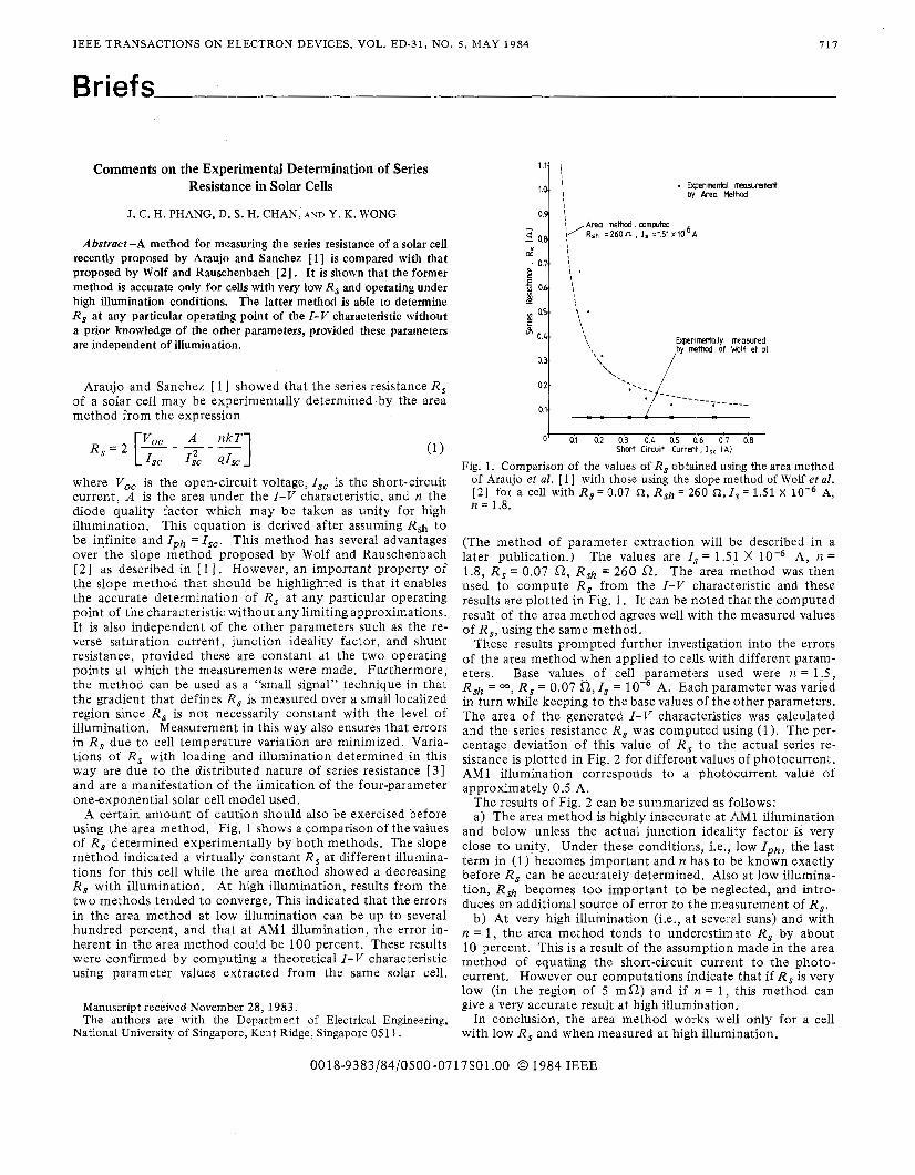
A certain amount of caution should also be exercised before using the area method. Fig. 1 shows a comparison of the values of R , determined experimentally by both methods. The slope method indicated a virtually constant R , at different illumina- tions for this cell while the area method showed a decreasing R , with illumination. At high illumination, results from the two methods tended to converge. This indicated that the errors in the area method at low illumination can be up to several hundred percent, and that at AM1 illumination, the error in- herent in the area method could be 100 percent. These results were confirmed by computing a theoretical I-V characteristic using parameter values extracted from the same solar cell.
Manuscript received November 28,1983. The authors are with the Department of Electrical Engineering,
National University of Singapore, Kent Ridge, Singapore 0511.
0’ 0.1 02 0.3 0.4 0.5 (1.6 0 7 08 7-
Shat Circult Current, ISc [ A I
Fig. 1. Comparison of the values of R, obtained using the area method of Araujo et al. [ 11 with those using the slope method of Wolf et al. [ 2 ] for a cell with R,= 0.07 a , R,h = 2160 a, I,= 1.51 X A, n = 1.8.
(The method of parameter extraction will be described in a later publication.) The values are I,* = 1.5 1 X A, n = 1.8, R, = 0.07 a, Rsh = 260 a. The area method was then used to compute R , from the I-V characteristic and these results are plotted in Fig. 1. It can be noted that the computed result of the area method agrees well with the measured values of R,, using the same method.
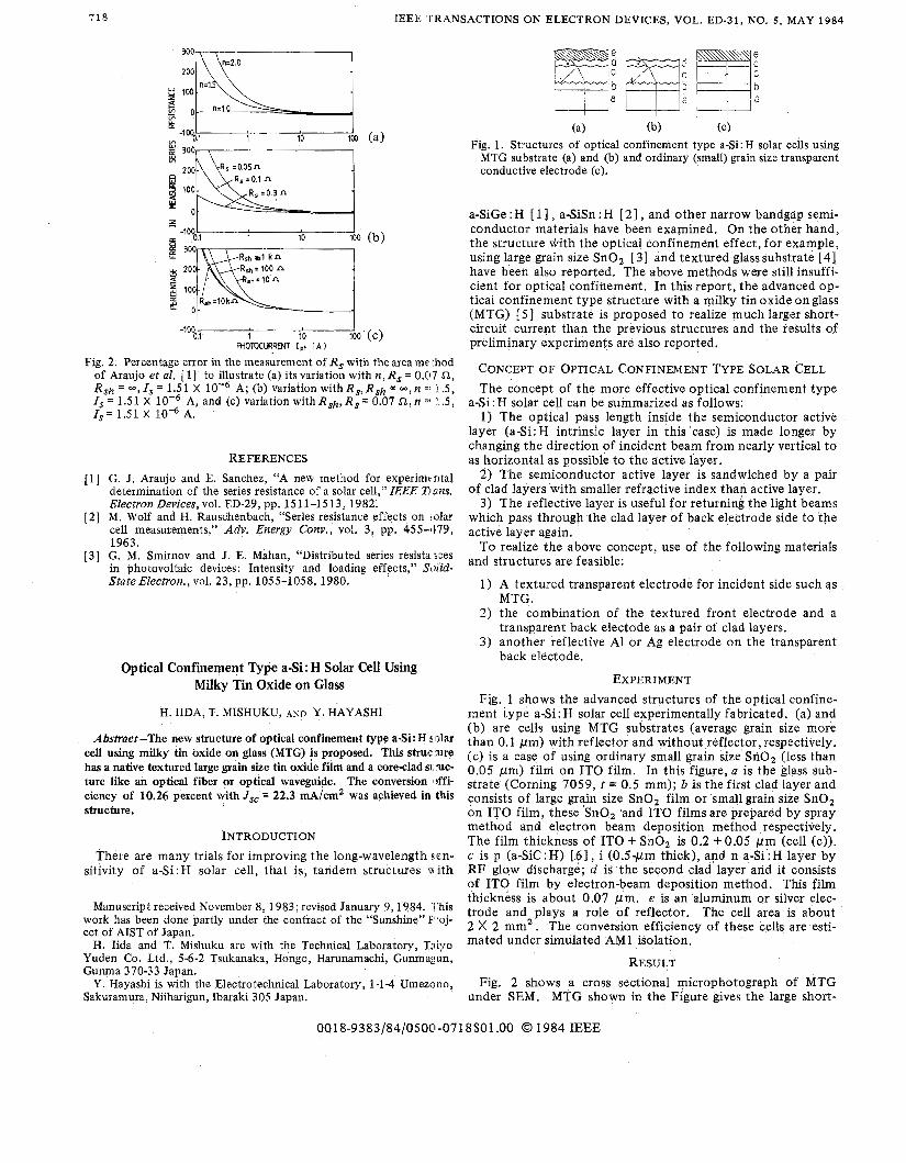
These results prompted further investigation into the errors of the area method when applied to cells with different param- eters. Base values of cell parameters used were n = 1.5, Rsh = 00, R , = 0.07 a, I , = A. Each parameter was varied in turn while keeping to the base values of the other parameters. The area of the generated I-V characteristics was calculated and the series resistance R , was computed using (1). The per- centage deviation of this value of R , to the actual series re- sistance is plotted in Fig. 2 for different values of photocurrent. AM1 illumination corresponds to a photocurrent value of approximately 0.5 A.
The results of Fig. 2 can be summarized as follows: a) The area method is highly inaccurate at AM1 illumination
and below unless the actual junction ideality factor is very close to unity. Under these conditions, i.e., low I p h , the last term in (1) becomes important and n has to be known exactly before R , can be accurately determined. Also at low illumina- tion, Rsh becomes too important to be neglected, and intro- duces an additional source of error to the measurement of R,.
b) At very high illumination (i,e., at several suns) and with n = 1, the area method tends to underestimate Rs by about 10 percent. This is a result of the assumption made in the area method of equating the short-circuit current to the photo- current. However our computations indicate that if R , is very low (in the region of 5 m a ) and if n = 1, this method can give a very accurate result at high illumination.
In conclusion, the area method works wel.1 only for a cell with low R, and when measured at high illumination.
0018-9383/84/0500-0717$01.00 0 1984 IEEE
710 IEEE TRANSACTIONS ON ELECTRON DEVICES, VOL. ED-31, NO. 5, MAY 1984
Z L p: -100 0.1 1 10 100
Rsh 1 k n R*= 100 n
* h = l O n
E R,h=lOkn 0
-loo 0.1 1 0 0 ’ (c) FFOTOCWIRENT I ph I A 1
10
Fig. 2. Percentage error in the measurement of R, with the area method of Araujo et al. 111 to illustrate (a) its variation with n. R , = 0.07 51. R,h = -, 1, = 1.51 X lov6 A; (b) variation with R,, Rsh = -, n :: : i 5 ;
I,= 1.51 X 10” A. I , = 1.51 X A, and (c) variation with R,h,R, = 0.07 a , n =: :,.5,
_ . I “
REFERENCES G. J. Araujo and E. Sanchez, “A new method for experimcntal determination of the series resistance of a solar cell,” IEEE Tlans. Electron Devices, vol. ED-29, pp. 1511-1513, 1982. M. Wolf and H. Rauschenbach, “Series resistance effects on !alar cell measurements,” Adu. Energy Conu., vol. 3, pp. 455-11’79, 1963. G. M. Smirnov and J. E. Mahan, “Distributed series resista xes in photovoltaic devices: Intensity and loading effects,” W i d - State Electron., vol. 23, pp. 1055-1058, 1980.
Optical Confinement Type a-Si : H Solar Cell Using Milky Tin Oxide on Glass
H. IIDA, T. MISHUKU, A N D Y. HAYASHI
Abstract-The new structure of optical confinement type a-Si:H !;[vlar cell using milky tin oxide on glass (MTG) is proposed. This struc :me has a native textured large grain see tin oxide film and a core-clad s1:ruc- ture like an optical fiber or optical waveguide. The conversion dfi- ciency of 10.26 percent with Jsc’= 22.3 mA/cm2 was achieved in this structure.
INTRODUCTION There are many trials for improving the long-wavelength !;en-
sitivity of a-Si:H solar cell, that is, tandem structures vtith
Manuscript received November 8, 1983; revised January 9,1984. ‘i’his work has been done partly under the contract of the “Sunshine” E‘:oj- ect of AIST of Japan.
H. Iida and T. Mishuku are with the Technical Laboratory, Tsiyo Yuden Co. Ltd., 5-6-2 Tsukanaka, Hongo, Harunamachi, Gunmagun, Gunma 370-33 Japan.
Y. Hayashi is with the Electrotechnical Laboratory, 1 - 1 4 Umezclno, Sakuramura, Niiharigun, Ibaraki 305 Japan.
(a) (b) (C) Fig. 1. Structures of optical confinement type a-Si: H solar ceils using
MTG substrate (a) and (b) and ordinary (small) grain size transparent conductive electrode (c).
a-SiGe : H [ 1 ] , a-SiSn : H [ 21 , and other narrow bandgap semi- conductor materials have been examined. On the other hand, the structure with the optical confinement effect, for example, using large grain size SnOz [3] and textured glasssubstrate [4] have been also reported. The above methods were still insuffi- cient for optical confinement. In this report, the advanced op- tical confinement type structure with a vilky tin oxide on glass (MTG) [ 51 substrate is proposed to realize much larger short- circuit current than the previous structures and the results of preliminary experiments are also reported.
CONCEPT OF OPTICAL CONFINEMENT TYPE SOLAR CELL The concept of the more effective optical confinement type
a-Si: H solar cell can be summarized as follows: 1) The optical pass length inside the semiconductor active
layer (a-Si:H intrinsic layer in this case) is made longer by changing the direction of incident beam from nearly vertical to as horizontal as possible to the active layer.
2 ) ?‘he semiconductor active layer is sandwiched by a pair of clad layers with smaller refractive index than active layer.
3) The reflective layer is useful for returning the light beams which pass throughthe clad layer of back electrode side to the active layer again.
To realize the above concept, use of the following materials and structures are feasible:
1) A textured transparent electrode for incident side such as
2 ) the combination of the textured front electrode and a
3) another reflective A1 or Ag electrode on the transparent
MTG.
transparent back electode as a pair of clad layers.
back electode.
EXPERIMENT Fig. 1 shows the advanced structures of the optical confine-
ment type a-Si:H solar cell experimentally fabricated. (a) and (b) are cells using MTG substrates (average grain size more than 0.1 pm) with reflector and without reflector,respectively. (c) is a case of using ordinary small grain size SnOz (less than 0.05 pm) f i lm on IT0 f i lm. In this f igure, a is the glass sub- strate (Corning 7059, t = 0.5 mm); b is the first clad layer and consists of large grain size SnO, film or small grain size SnO, on IT0 film, these SnO, and !TO films are prepared by spray method and electron beam deposition method respectively. The film thickness of I T 0 + SnO, is 0.2 + 0.05 p m (cell (c)). c is p (a-Sic : H) [.6 I , i (0.5-pm thick), and n a-Si : H layer by R F glow discharge; d is the second clad layer and it consists of I T 0 film by electron-beam deposition method. This film thickness is about 0.07 p m . e is an aluminum or silver elec- trode and plays a role of reflector. The cell area is about 2 X 2 mm2 , The conversion efficiency of these cells are esti- mated under simulated AM1 isolation.
RESULT Fig. 2 shows a cross sectional microphotograph of MTG
under SEM. MTG shown in the Figure gives the large short-
0018-9383/84/0500-0718$01.00 @ 1984 IEEE


![B.Sc. Physics Course Structure under CBCS · Determination of the Refractive Index [µ] of glass using a prism and a spectrometer. 7. Determination of Resistance and Specific Resistance](https://img.pdfslide.us/doc/110x75/5e0f8795275cca046b696474/bsc-physics-course-structure-under-determination-of-the-refractive-index-.jpg)