Embed Size (px)
Citation preview
Page 1
Comments on the "Availability assessment of ALSTOM's safety-relevant trainborne odometry sub-system"
Dr. Borivoje Stamenkoviċ
TLS 45 Consulting GmbH, 3172 Niederwangen, Switzerland (December 2012)
Abstract
In more than 12 years, ALSTOM's trainborne ERTMS/ETCS solutions have been applied worldwide by many new railways projects (in Spain, Switzerland, Italy, Austria, Denmark, etc.).
In order to achieve the best safety-related and availability performances of safety-relevant vital functionalities, the 2-out-of-3 (2oo3) protection architecture is applied for the three European Vital Computer (EVC) basic channels.
The correct availability modelling of the spurious Emergency Brakes (EB) application needs to present a correct availability modelling for the odometry sub-system.
In this paper a correct availability modelling of the odometry subsystem is presented, as well as the complete solution for the calculation of the Mean operating Time Between System Failures (MTBSF) related to the spurious EB application.
1 Introduction
In [1], an approximate algebraic solution has been presented for the availability assessment of ALSTOM's safety-relevant trainborne odometry sub-system. In the present article, the complete availability model of odometry sub-system has been developed, and the solution is extended to the spurious EB application. Instead of using approximate solutions for the impact of odometry sub-system and approximate expressions for the estimation of the resulting MTBSF (or system failure rate) for spurious EB application, a BQR CARE-FTA software tool [3] is used to obtain a complete solution.
2 Odometry Sensor Configuration
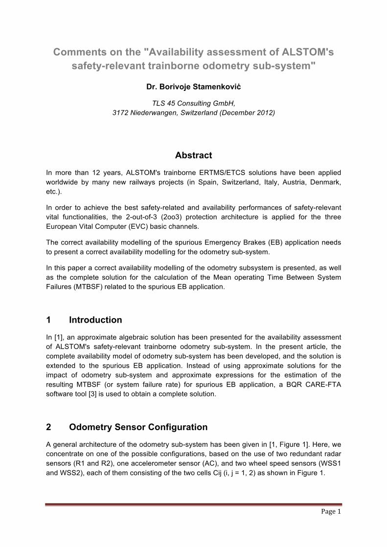
A general architecture of the odometry sub-system has been given in [1, Figure 1]. Here, we concentrate on one of the possible configurations, based on the use of two redundant radar sensors (R1 and R2), one accelerometer sensor (AC), and two wheel speed sensors (WSS1 and WSS2), each of them consisting of the two cells Cij (i, j = 1, 2) as shown in Figure 1.
Page 2
Figure 1: Odometry sensor configuration; Five sensor signals of two radars (R1 and R2), one accelerometer (AC), and four wheel speed sensor cells WSSCij = Cij, (i, j = 1, 2) are conducted to EVC channel ii (CH ii) (i = 1, 2, 3).
3 Reliability Block Diagram (RBD) for the Spurious Emergency Brakes (EB) Application
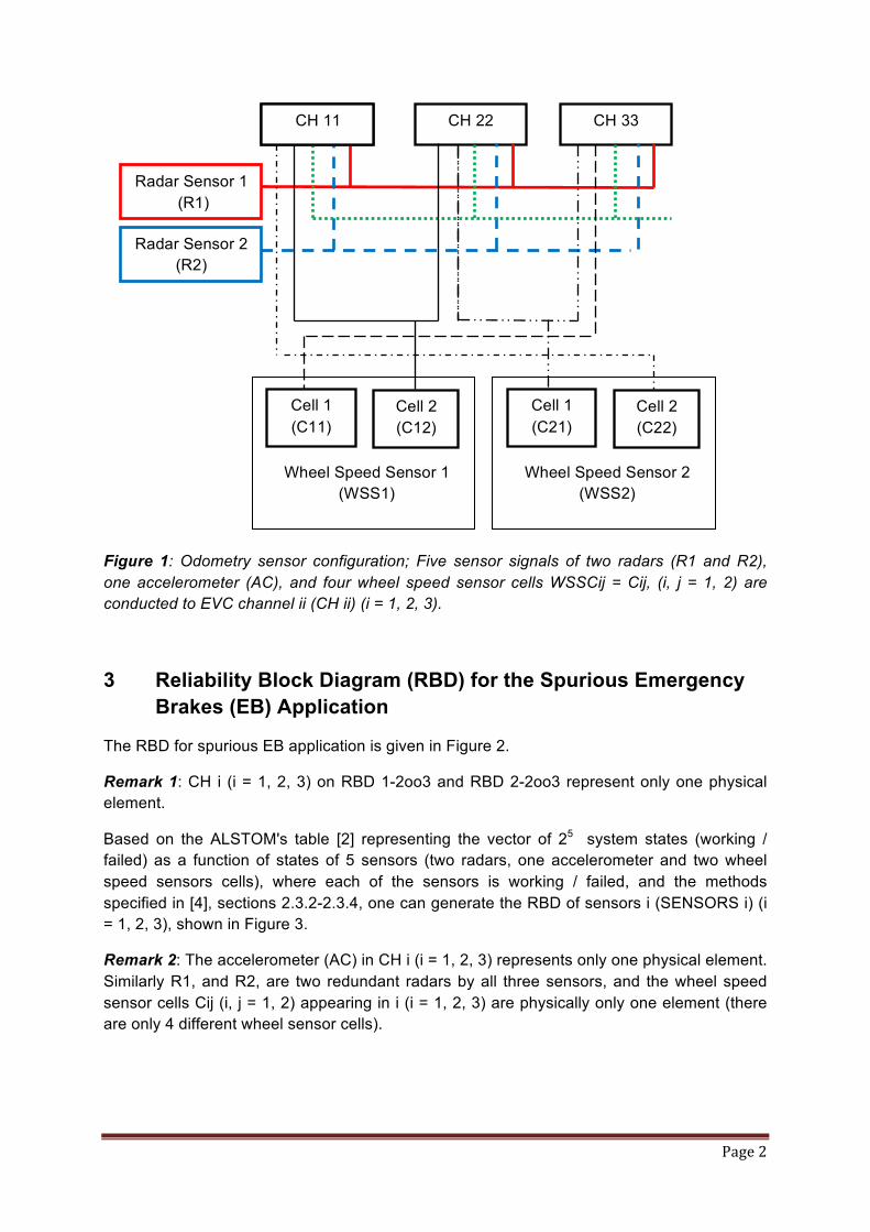
The RBD for spurious EB application is given in Figure 2.
Remark 1: CH i (i = 1, 2, 3) on RBD 1-2oo3 and RBD 2-2oo3 represent only one physical element.
Based on the ALSTOM's table [2] representing the vector of 25 system states (working / failed) as a function of states of 5 sensors (two radars, one accelerometer and two wheel speed sensors cells), where each of the sensors is working / failed, and the methods specified in [4], sections 2.3.2-2.3.4, one can generate the RBD of sensors i (SENSORS i) (i = 1, 2, 3), shown in Figure 3.
Remark 2: The accelerometer (AC) in CH i (i = 1, 2, 3) represents only one physical element. Similarly R1, and R2, are two redundant radars by all three sensors, and the wheel speed sensor cells Cij (i, j = 1, 2) appearing in i (i = 1, 2, 3) are physically only one element (there are only 4 different wheel sensor cells).
ODO 1 CH 22 CH 33
Radar Sensor 1 (R1)
Radar Sensor 2 (R2)
Cell 1 (C11)
Cell 2 (C12)
Wheel Speed Sensor 1 (WSS1)
Cell 1 (C21)
Cell 2 (C22)
Wheel Speed Sensor 2 (WSS2)
CH 11
Page 3
Figure 2: RBD for spurious EB application; S = Start and E = End of the RBD; RBD i-2oo3 (i = 1, 2) consisting of the Brake Request Relays BRR ij (i = 1, 2, 3; j = 1, 2) of the i-th channel (CH i, and RBD 3 - RBD of Peripherals consisting of Eurobalise Subsystem (TES) and Back Plane (BP).
Remark 3: In [1, Figure 2], the odometry sub-system has used one radar instead of two redundant radars, and the approximate solution has been presented based on the use of a 3-out-of-4 (3oo4) protection architecture of one radar, one accelerometer and two wheel speed sensors, each of them with two sensor cells. It has been noted in [1], that the presented solution is only one approximation. It can easily be shown that each of the RBD sensors i, shown in Figure 3, with one radar will be absorbed by 3oo4 protection architecture proposed in [1, Figure 2].
4 Availability Modelling with the BQR CARE-FTA Software Tool
The BQR CARE-FTA software tool [3] will be applied for RBD 1-2oo3 and RBD 2-2oo3 to calculate the availability, the Mean operating Time Between System Failure (MTBSF) (or alternatively - System Failure Rate ) for the Mean Time to Restoration / Recovery (MTTR) MTTR = 10 h. It is pointed out, that the consideration is based on the assumption that each original "end cause event" in CARE-FTA is a functional or constructive block, which can be failed and repaired independently of the other ones.
To solve RBD i-2oo3 (i = 1, 2, 3), specified with the 2oo3 protection architecture, with [3], let us apply the "Successful Part Transformation (SPT)" shown in Figure 4, where RBD i-SP is based on the successful paths (A AND B; A AND C, and B AND C).
CH 1
CH 2
CH 3
BRR 11
BRR 31
BRR 21 2oo3
S
Peripherals
RBD 3
RBD 1-2oo3
CH 1
CH 2
CH 3
BRR 12
BRR 32
BRR 22 2oo3
RBD 2-2oo3
E
Page 4
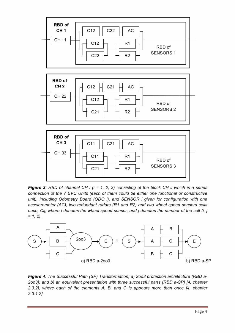
Figure 3: RBD of channel CH i (i = 1, 2, 3) consisting of the block CH ii which is a series connection of the 7 EVC Units (each of them could be either one functional or constructive unit), including Odometry Board (ODO i), and SENSOR i given for configuration with one accelerometer (AC), two redundant radars (R1 and R2) and two wheel speed sensors cells each, Cij, where i denotes the wheel speed sensor, and j denotes the number of the cell (i, j = 1, 2).
Figure 4: The Successful Path (SP) Transformation; a) 2oo3 protection architecture (RBD a-2oo3); and b) an equivalent presentation with three successful parts (RBD a-SP) [4, chapter 2.3.2], where each of the elements A, B, and C is appears more than once [4, chapter 2.3.1.2].
CH 11 C12
C22 AC C12
C22
R1
R2
RBD of SENSORS 1
RBD of CH 1
CH 22 C12
C21 AC C12
C21
R1
R2
RBD of SENSORS 2
RBD of CH 2
CH 33 C11
C21 AC C11
C21
R1
R2
RBD of SENSORS 3
RBD of CH 3
S
A
B
C a) RBD a-2oo3
A
A
B
B
C
C S ≡ E E
b) RBD a-SP
2oo3
Page 5
The RBD a-SP shown in Figure 4, b) allows one to apply [3], where each block X (X = A, B, C) appears one time as "Original" and the second time is copied with "Paste common cause" of a physically identical unit.
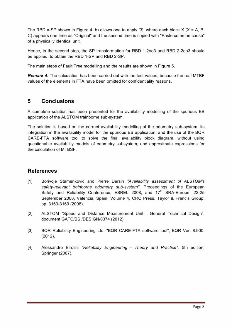
Hence, in the second step, the SP transformation for RBD 1-2oo3 and RBD 2-2oo3 should be applied, to obtain the RBD 1-SP and RBD 2-SP.
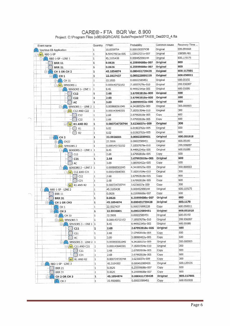
The main steps of Fault Tree modelling and the results are shown in Figure 5.
Remark 4: The calculation has been carried out with the test values, because the real MTBF values of the elements in FTA have been omitted for confidentiality reasons.
5 Conclusions
A complete solution has been presented for the availability modelling of the spurious EB application of the ALSTOM trainborne sub-system.
The solution is based on the correct availability modelling of the odometry sub-system, its integration in the availability model for the spurious EB application, and the use of the BQR CARE-FTA software tool to solve the final availability block diagram, without using questionable availability models of odometry subsystem, and approximate expressions for the calculation of MTBSF.
References
[1] Borivoje Stamenkoviċ and Pierre Dersin "Availability assessment of ALSTOM's safety-relevant trainborne odometry sub-system", Proceedings of the European Safety and Reliability Conference, ESREL 2008, and 17th SRA-Europe, 22-25 September 2008, Valencia, Spain, Volume 4, CRC Press, Taylor & Francis Group: pp. 3163-3169 (2008).
[2] ALSTOM "Speed and Distance Measurement Unit - General Technical Design", document GATC/BSI/DESIGN/0374 (2012). [3] BQR Reliability Engineering Ltd. "BQR CARE-FTA software tool", BQR Ver. 8.900, (2012). [4] Alessandro Birolini "Reliability Engineering - Theory and Practice", 5th edition, Springer (2007).
Page 6
Page 7
Figure 5: Trainborne Subsystem; FTA for Spurious EB Application; Legend: (a) FPMH (failure per milion hours); (b) Probability (Unavailability); (c) Recovery Time (MTTR = 10 hours).