Embed Size (px)
Citation preview
Command Reference Networking OS 7.8 for 1/10Gb LAN Switch Module
Product Version
Getting Help
Contents
FASTFIND LINKS

ii
Command Reference
© 2014 Hitachi, Ltd. All rights reserved.
No part of this publication may be reproduced or transmitted in any form or by any
means, electronic or mechanical, including photocopying and recording, or stored in a database or retrieval system for any purpose without the express written
permission of Hitachi, Ltd.
Hitachi, Ltd., reserves the right to make changes to this document at any time without notice and assumes no responsibility for its use. This document contains
the most current information available at the time of publication. When new or revised information becomes available, this entire document will be updated and
distributed to all registered users.
Some of the features described in this document might not be currently available. Refer to the most recent product announcement for information about feature and
product availability, or contact your reseller.
All other trademarks, service marks, and company names in this document or
website are properties of their respective owners.
Microsoft® product screen shots are reprinted with permission from Microsoft Corporation.
Contents iii
Command Reference
Contents
Preface .................................................................................................... v
Intended Audience ............................................................................................... vi Product Version .................................................................................................... vi Release Notes ...................................................................................................... vi Referenced Documents ......................................................................................... vi Document Conventions ......................................................................................... vii Convention for storage capacity values ................................................................. viii Getting Help........................................................................................................ viii
CLI Basics ............................................................................................. 1-1
Information Commands .......................................................................... 2-1
Statistics Commands .............................................................................. 3-1
Configuration Commands ....................................................................... 4-1
Operations Commands ........................................................................... 5-1
Boot Options ......................................................................................... 6-1
Maintenance Commands ........................................................................ 7-1
Appendix A ............................................................................................ A-1

Preface v
Command Reference
Preface
This document describes how to use the Hitachi BladeSymphony 1/10Gb LAN Switch Module. The Networking OS 7.8 Command Reference describes how to
configure and use the Networking OS 7.8 software with your Hitachi BladeSymphony 1/10Gb LAN Switch Module. This guide lists each command, together with the complete syntax and a functional description, from the
Command Line Interface (CLI).
This preface includes the following information:
Intended Audience
Product Version
Release Notes
Referenced Documents
Document Conventions
Convention for storage capacity values
Getting Help
vi Preface
Command Reference
Intended Audience
This book is intended for network installers and system administrators engaged in configuring and maintaining a network. The administrator should
be familiar with Ethernet concepts, IP addressing, the Spanning Tree Protocol and SNMP configuration parameters.
Product Version
This document revision applies to 1/10Gb LAN Switch Module version
Networking OS 7.8.
Release Notes
Read the release notes before installing and using this product. They may contain requirements or restrictions that are not fully described in this
document or updates or corrections to this document.
Referenced Documents
1/10Gb LAN Switch Module documents:
Networking OS Application Guide
Networking OS Browser-Based Interface Quick Guide
Preface vii
Command Reference
Document Conventions
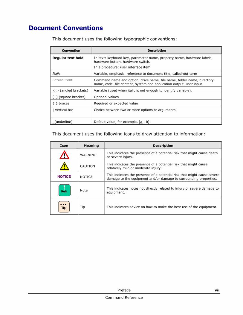
This document uses the following typographic conventions:
Convention Description
Regular text bold In text: keyboard key, parameter name, property name, hardware labels, hardware button, hardware switch.
In a procedure: user interface item
Italic Variable, emphasis, reference to document title, called-out term
Screen text Command name and option, drive name, file name, folder name, directory name, code, file content, system and application output, user input
< > (angled brackets) Variable (used when italic is not enough to identify variable).
[ ] (square bracket) Optional values
{ } braces Required or expected value
| vertical bar Choice between two or more options or arguments
_(underline) Default value, for example, [a | b]
This document uses the following icons to draw attention to information:
Icon Meaning Description
WARNING
This indicates the presence of a potential risk that might cause death or severe injury.
CAUTION
This indicates the presence of a potential risk that might cause relatively mild or moderate injury.
NOTICE NOTICE This indicates the presence of a potential risk that might cause severe damage to the equipment and/or damage to surrounding properties.
Note This indicates notes not directly related to injury or severe damage to equipment.
Tip This indicates advice on how to make the best use of the equipment.
viii Preface
Command Reference
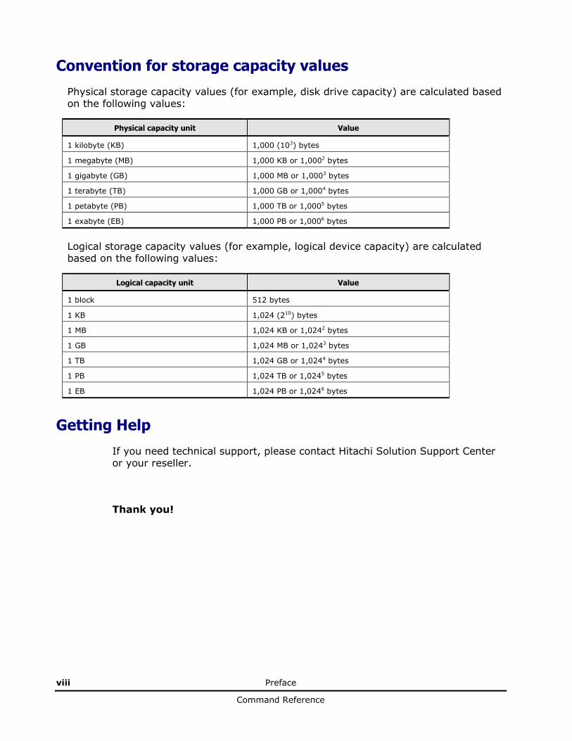
Convention for storage capacity values
Physical storage capacity values (for example, disk drive capacity) are calculated based on the following values:
Physical capacity unit Value
1 kilobyte (KB) 1,000 (103) bytes
1 megabyte (MB) 1,000 KB or 1,0002 bytes
1 gigabyte (GB) 1,000 MB or 1,0003 bytes
1 terabyte (TB) 1,000 GB or 1,0004 bytes
1 petabyte (PB) 1,000 TB or 1,0005 bytes
1 exabyte (EB) 1,000 PB or 1,0006 bytes
Logical storage capacity values (for example, logical device capacity) are calculated based on the following values:
Logical capacity unit Value
1 block 512 bytes
1 KB 1,024 (210) bytes
1 MB 1,024 KB or 1,0242 bytes
1 GB 1,024 MB or 1,0243 bytes
1 TB 1,024 GB or 1,0244 bytes
1 PB 1,024 TB or 1,0245 bytes
1 EB 1,024 PB or 1,0246 bytes
Getting Help
If you need technical support, please contact Hitachi Solution Support Center or your reseller.
Thank you!
1
CLI Basics 1-1
Command Reference
CLI Basics
Your 1/10Gb LAN Switch Module is ready to perform basic switching functions
right out of the box. Some of the more advanced features, however, require some administrative configuration before they can be used effectively.
This guide describes the individual CLI commands available for 1/10Gb LAN
Switch Module.
The CLI provides a direct method for collecting switch information and performing switch configuration. Using a basic terminal, the CLI allows you to
view information and statistics about the switch, and to perform any necessary configuration.
This chapter explains how to access the Command Line Interface (CLI) for the
switch.
Accessing the CLI
CLI Command Modes
Global Commands
Command Line Interface Shortcuts
User Access Levels
Idle Timeout
1-2 CLI Basics
Command Reference
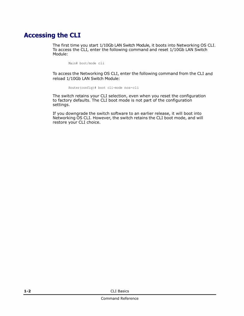
Accessing the CLI
The first time you start 1/10Gb LAN Switch Module, it boots into Networking OS CLI. To access the CLI, enter the following command and reset 1/10Gb LAN Switch Module:
Main# boot/mode cli
To access the Networking OS CLI, enter the following command from the CLI and
reload 1/10Gb LAN Switch Module:
Router(config)# boot cli-mode nos-cli
The switch retains your CLI selection, even when you reset the configuration to factory defaults. The CLI boot mode is not part of the configuration settings. If you downgrade the switch software to an earlier release, it will boot into Networking OS CLI. However, the switch retains the CLI boot mode, and will restore your CLI choice.
CLI Basics 1-3
Command Reference
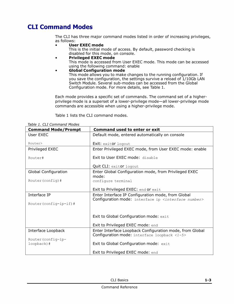
CLI Command Modes
The CLI has three major command modes listed in order of increasing privileges, as follows: • User EXEC mode
This is the initial mode of access. By default, password checking is disabled for this mode, on console.
• Privileged EXEC mode This mode is accessed from User EXEC mode. This mode can be accessed using the following command: enable
• Global Configuration mode This mode allows you to make changes to the running configuration. If you save the configuration, the settings survive a reload of 1/10Gb LAN Switch Module. Several sub-modes can be accessed from the Global Configuration mode. For more details, see Table 1.
Each mode provides a specific set of commands. The command set of a higher-
privilege mode is a superset of a lower-privilege mode—all lower-privilege mode
commands are accessible when using a higher-privilege mode.
Table 1 lists the CLI command modes.
Table 1. CLI Command Modes
Command Mode/Prompt Command used to enter or exit
User EXEC
Router>
Default mode, entered automatically on console
Exit: exit or logout
Privileged EXEC Router#
Enter Privileged EXEC mode, from User EXEC mode: enable Exit to User EXEC mode: disable Quit CLI: exit or logout
Global Configuration Router(config)#
Enter Global Configuration mode, from Privileged EXEC
mode: configure terminal
Exit to Privileged EXEC: end or exit
Interface IP Router(config-ip-if)#
Enter Interface IP Configuration mode, from Global Configuration mode: interface ip <interface number>
Exit to Global Configuration mode: exit Exit to Privileged EXEC mode: end
Interface Loopback Router(config-ip-
loopback)#
Enter Interface Loopback Configuration mode, from Global Configuration mode: interface loopback <1-5> Exit to Global Configuration mode: exit Exit to Privileged EXEC mode: end

1-4 CLI Basics
Command Reference
Table 1. CLI Command Modes (continued)
Command Mode/Prompt Command used to enter or exit
Interface Port
Router(config-if)#
Enter Port Configuration mode, from Global Configuration mode: interface port <port number or alias>
Exit to Privileged EXEC mode: exit
Exit to Global Configuration mode: end
Interface PortChannel
Router(config-PortChannel)#
Enter PortChannel (trunk group) Configuration mode,
from Global Configuration mode: interface portchannel {<trunk number>|lacp
<key>}
Exit to Privileged EXEC mode: exit Exit to Global Configuration mode: end
VLAN
Router(config-vlan)#
Enter VLAN Configuration mode, from Global Configuration mode: vlan <VLAN number>
Exit to Global Configuration mode: exit Exit to Privileged EXEC mode: end
Router OSPF
Router(config-router-ospf)#
Enter OSPF Configuration mode, from Global Configuration mode: router ospf
Exit to Global Configuration mode: exit Exit to Privileged EXEC mode: end
Router BGP
Router(config-router-bgp)#
Enter BGP Configuration mode, from Global Configuration mode: router bgp
Exit to Global Configuration mode: exit Exit to Privileged EXEC mode: end
Router RIP
Router(config-router-rip)#
Enter RIP Configuration mode, from Global
Configuration mode: router rip
Exit to Global Configuration mode: exit
Exit to Privileged EXEC mode: end
Route Map Router(config-route-map)#
Enter Route Map Configuration mode, from Global Configuration mode: route-map <1-32>
Exit to Global Configuration mode: exit Exit to Privileged EXEC mode: end
CLI Basics 1-5
Command Reference
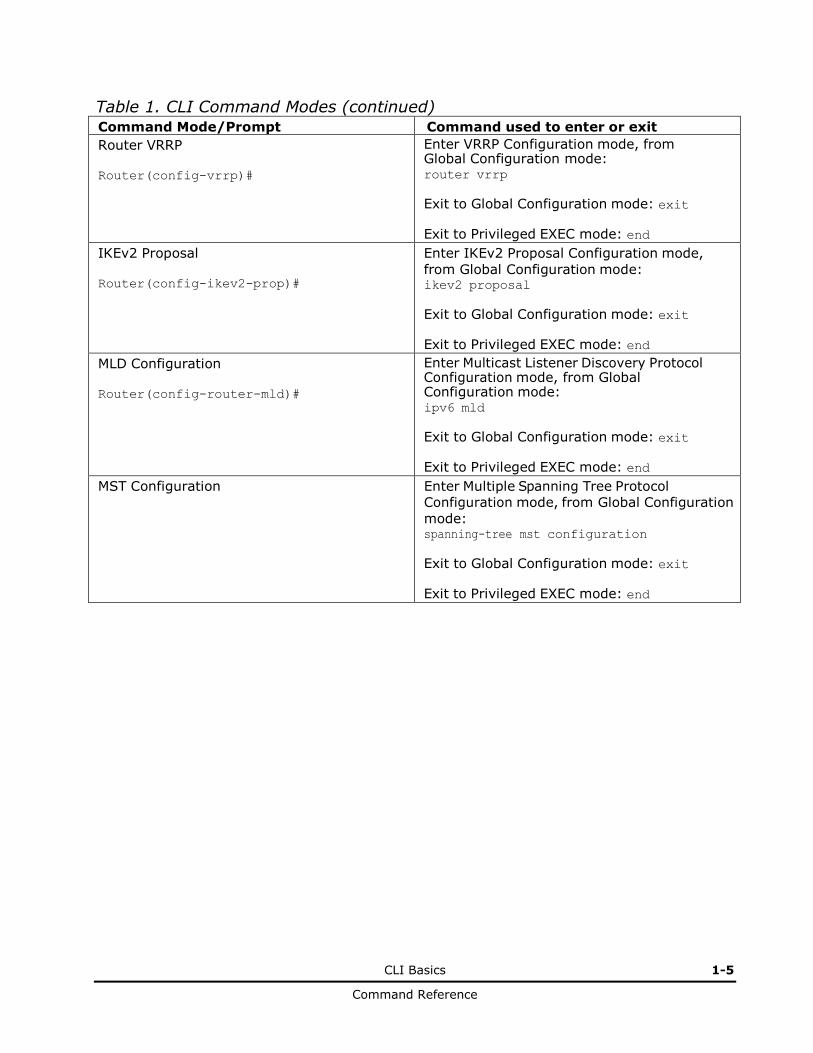
Table 1. CLI Command Modes (continued) Command Mode/Prompt Command used to enter or exit
Router VRRP Router(config-vrrp)#
Enter VRRP Configuration mode, from Global Configuration mode: router vrrp
Exit to Global Configuration mode: exit Exit to Privileged EXEC mode: end
IKEv2 Proposal Router(config-ikev2-prop)#
Enter IKEv2 Proposal Configuration mode,
from Global Configuration mode: ikev2 proposal
Exit to Global Configuration mode: exit Exit to Privileged EXEC mode: end
MLD Configuration Router(config-router-mld)#
Enter Multicast Listener Discovery Protocol Configuration mode, from Global Configuration mode: ipv6 mld
Exit to Global Configuration mode: exit Exit to Privileged EXEC mode: end
MST Configuration Enter Multiple Spanning Tree Protocol
Configuration mode, from Global Configuration
mode: spanning-tree mst configuration
Exit to Global Configuration mode: exit Exit to Privileged EXEC mode: end
1-6 CLI Basics
Command Reference
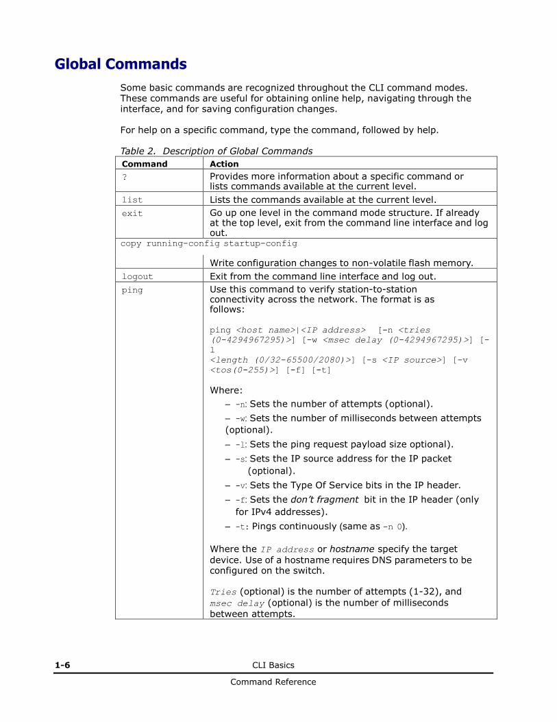
Global Commands
Some basic commands are recognized throughout the CLI command modes. These commands are useful for obtaining online help, navigating through the interface, and for saving configuration changes. For help on a specific command, type the command, followed by help. Table 2. Description of Global Commands
Command Action
? Provides more information about a specific command or lists commands available at the current level.
list Lists the commands available at the current level.
exit Go up one level in the command mode structure. If already at the top level, exit from the command line interface and log out.
copy running-config startup-config
Write configuration changes to non-volatile flash memory.
logout Exit from the command line interface and log out.
ping Use this command to verify station-to-station connectivity across the network. The format is as follows: ping <host name>|<IP address> [-n <tries
(0-4294967295)>] [-w <msec delay (0-4294967295)>] [-
l <length (0/32-65500/2080)>] [-s <IP source>] [-v
<tos(0-255)>] [-f] [-t]
Where:
– -n: Sets the number of attempts (optional).
– -w: Sets the number of milliseconds between attempts
(optional).
– -l: Sets the ping request payload size optional).
– -s: Sets the IP source address for the IP packet
(optional).
– -v: Sets the Type Of Service bits in the IP header.
– -f: Sets the don’t fragment bit in the IP header (only
for IPv4 addresses).
– -t: Pings continuously (same as -n 0).
Where the IP address or hostname specify the target
device. Use of a hostname requires DNS parameters to be configured on the switch.
Tries (optional) is the number of attempts (1-32), and
msec delay (optional) is the number of milliseconds
between attempts.
CLI Basics 1-7
Command Reference
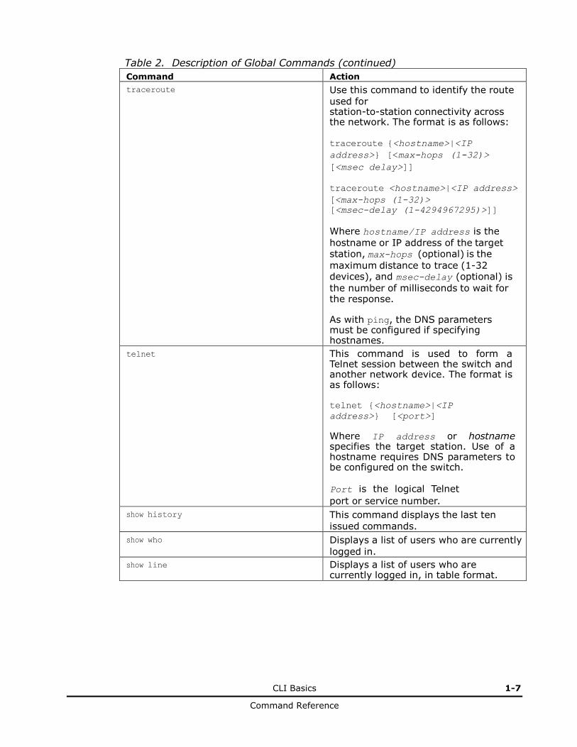
Table 2. Description of Global Commands (continued)
Command Action
traceroute Use this command to identify the route
used for station-to-station connectivity across the network. The format is as follows:
traceroute {<hostname>|<IP
address>} [<max-hops (1-32)> [<msec delay>]]
traceroute <hostname>|<IP address>
[<max-hops (1-32)>
[<msec-delay (1-4294967295)>]]
Where hostname/IP address is the
hostname or IP address of the target station, max-hops (optional) is the
maximum distance to trace (1-32 devices), and msec-delay (optional) is
the number of milliseconds to wait for the response. As with ping, the DNS parameters must be configured if specifying hostnames.
telnet This command is used to form a Telnet session between the switch and another network device. The format is as follows: telnet {<hostname>|<IP
address>} [<port>]
Where IP address or hostname specifies the target station. Use of a hostname requires DNS parameters to be configured on the switch.
Port is the logical Telnet
port or service number.
show history This command displays the last ten
issued commands.
show who Displays a list of users who are currently
logged in.
show line Displays a list of users who are currently logged in, in table format.

1-8 CLI Basics
Command Reference
Command Line Interface Shortcuts
The following shortcuts allow you to enter commands quickly and easily.
CLI List and Range Inputs For VLAN and port commands that allow an individual item to be selected from within a numeric range, lists and ranges of items can now be specified. For example, the vlan command permits the following options:
# vlan 1,3,4095 (access VLANs 1, 3, and 4095)
# vlan 1-20 (access VLANs 1 through 20)
# vlan 1-5,90-99,4090-4095 (access multiple ranges)
# vlan 1-5,19,20,4090-4095 (access a mix of lists and ranges)
The numbers in a range must be separated by a dash: <start of range>-<end of range>
Multiple ranges or list items are permitted using a comma: <range or item 1>,<range or item 2>
Do not use spaces within list and range specifications.
Ranges can also be used to apply the same command option to multiple items. For example, to access multiple ports with one command:
# interface port 1-4 (Access ports 1 though 4)
Command Abbreviation
Most commands can be abbreviated by entering the first characters which distinguish the command from the others in the same mode. For example, consider the following full command and a valid abbreviation:
Router(config)# spanning-tree stp 2 bridge hello 2
or Router(config)# sp stp 2 br h 2
Tab Completion
By entering the first letter of a command at any prompt and pressing <Tab>, the CLI displays all available commands or options that begin with that letter. Entering additional letters further refines the list of commands or options displayed. If only one command fits the input text when <Tab> is pressed, that command is supplied on the command line, waiting to be entered.
CLI Basics 1-9
Command Reference
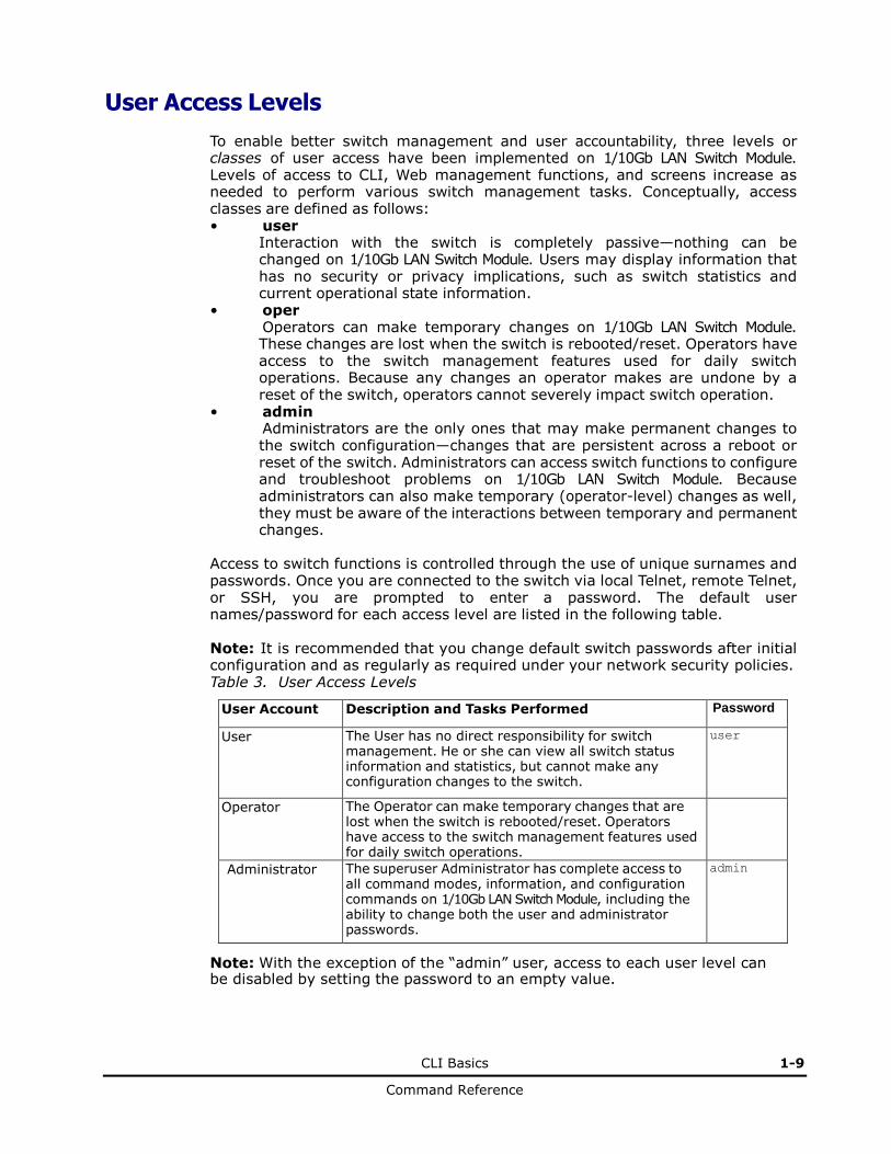
User Access Levels
To enable better switch management and user accountability, three levels or classes of user access have been implemented on 1/10Gb LAN Switch Module. Levels of access to CLI, Web management functions, and screens increase as needed to perform various switch management tasks. Conceptually, access classes are defined as follows: • user
Interaction with the switch is completely passive—nothing can be changed on 1/10Gb LAN Switch Module. Users may display information that has no security or privacy implications, such as switch statistics and current operational state information.
• oper Operators can make temporary changes on 1/10Gb LAN Switch Module. These changes are lost when the switch is rebooted/reset. Operators have access to the switch management features used for daily switch operations. Because any changes an operator makes are undone by a reset of the switch, operators cannot severely impact switch operation.
• admin Administrators are the only ones that may make permanent changes to the switch configuration—changes that are persistent across a reboot or reset of the switch. Administrators can access switch functions to configure and troubleshoot problems on 1/10Gb LAN Switch Module. Because administrators can also make temporary (operator-level) changes as well, they must be aware of the interactions between temporary and permanent changes.
Access to switch functions is controlled through the use of unique surnames and passwords. Once you are connected to the switch via local Telnet, remote Telnet, or SSH, you are prompted to enter a password. The default user names/password for each access level are listed in the following table. Note: It is recommended that you change default switch passwords after initial configuration and as regularly as required under your network security policies. Table 3. User Access Levels
User Account Description and Tasks Performed Password
User The User has no direct responsibility for switch management. He or she can view all switch status information and statistics, but cannot make any configuration changes to the switch.
user
Operator The Operator can make temporary changes that are lost when the switch is rebooted/reset. Operators have access to the switch management features used for daily switch operations.
Administrator The superuser Administrator has complete access to all command modes, information, and configuration commands on 1/10Gb LAN Switch Module, including the ability to change both the user and administrator passwords.
admin
Note: With the exception of the “admin” user, access to each user level can be disabled by setting the password to an empty value.

1-10 CLI Basics
Command Reference
Idle Timeout
By default, the switch will disconnect your Telnet session after ten minutes of inactivity. This function is controlled by the following command, which can be set from 1 to 60 minutes, or disabled when set to 0:
system idle <0-60>
Command mode: Global Configuration
2
Information Commands 2-1
Command Reference
Information Commands
You can view configuration information for the switch in both the user and
administrator command modes. This chapter discusses how to use the command line interface to display switch information.
Information Commands
System Information
Layer 2 Information
Layer 3 Information
RMON Information Commands
Port Information
Port Transceiver Status
Virtual Machines Information
SLP Information
Information Dump

2-2 Information Commands
Command Reference
Information Commands
You can view configuration information for the switch in both the user and administrator command modes. This chapter discusses how to use the command line interface to display switch information.
Table 4. Information Commands
Command Syntax and Usage
show interface status <port alias or number>
Displays configuration information about the selected port(s), including:
– Port alias and number
– Port speed
– Duplex mode (half, full, or auto)
– Flow control for transmit and receive (no, yes, or both)
– Link status (up, down, or disabled)
For details, see page 2-89.
Command mode: All
show interface trunk <port alias or number>
Displays port status information, including:
– Port alias and number
– Whether the port uses VLAN Tagging or not
– Port VLAN ID (PVID)
– Port name
– VLAN membership
– FDB Learning status
– Flooding status
For details, see page 2-91.
Command mode: All
show interface transceiver
Displays the status of the port transceiver module on each external port. For details, see page 2-93.
Command mode: All
show software-key
Displays the enabled software features.
Command mode: All
show information-dump
Dumps all switch information available (10K or more, depending on your configuration).
If you want to capture dump data to a file, set your communication software on your workstation to capture session data prior to issuing the dump commands.
Command mode: All
Information Commands 2-3
Command Reference
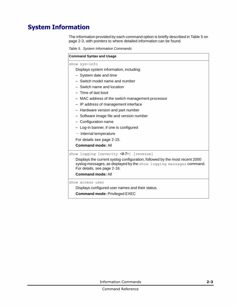
System Information
The information provided by each command option is briefly described in Table 5 on page 2-3, with pointers to where detailed information can be found.
Table 5. System Information Commands
Command Syntax and Usage
show sys-info
Displays system information, including:
– System date and time
– Switch model name and number
– Switch name and location
– Time of last boot
– MAC address of the switch management processor
– IP address of management interface
– Hardware version and part number
– Software image file and version number
– Configuration name
– Log-in banner, if one is configured
- Internal temperature
For details see page 2-15.
Command mode: All
show logging [severity <0-7>] [reverse]
Displays the current syslog configuration, followed by the most recent 2000 syslog messages, as displayed by the show logging messages command.
For details, see page 2-16.
Command mode: All
show access user
Displays configured user names and their status.
Command mode: Privileged EXEC
2-4 Information Commands
Command Reference
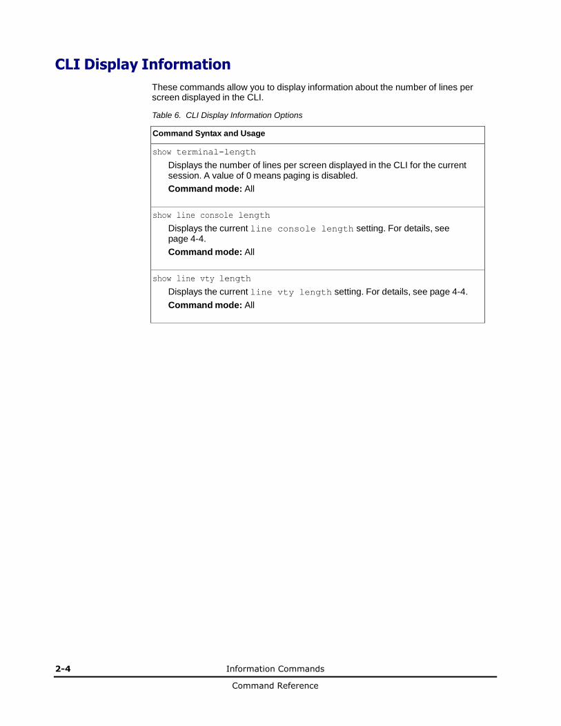
CLI Display Information
These commands allow you to display information about the number of lines per screen displayed in the CLI.
Table 6. CLI Display Information Options
Command Syntax and Usage
show terminal-length
Displays the number of lines per screen displayed in the CLI for the current session. A value of 0 means paging is disabled.
Command mode: All
show line console length
Displays the current line console length setting. For details, see page 4-4.
Command mode: All
show line vty length
Displays the current line vty length setting. For details, see page 4-4.
Command mode: All
Information Commands 2-5
Command Reference
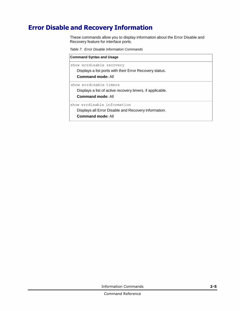
Error Disable and Recovery Information
These commands allow you to display information about the Error Disable and Recovery feature for interface ports.
Table 7. Error Disable Information Commands
Command Syntax and Usage
show errdisable recovery
Displays a list ports with their Error Recovery status.
Command mode: All
show errdisable timers
Displays a list of active recovery timers, if applicable.
Command mode: All
show errdisable information
Displays all Error Disable and Recovery information.
Command mode: All
2-6 Information Commands
Command Reference
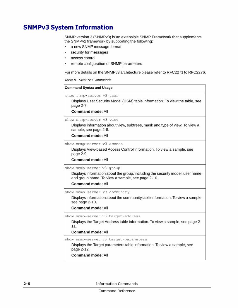
SNMPv3 System Information
SNMP version 3 (SNMPv3) is an extensible SNMP Framework that supplements the SNMPv2 framework by supporting the following:
• a new SNMP message format
• security for messages
• access control
• remote configuration of SNMP parameters
For more details on the SNMPv3 architecture please refer to RFC2271 to RFC2276.
Table 8. SNMPv3 Commands
Command Syntax and Usage
show snmp-server v3 user
Displays User Security Model (USM) table information. To view the table, see page 2-7.
Command mode: All
show snmp-server v3 view
Displays information about view, subtrees, mask and type of view. To view a sample, see page 2-8.
Command mode: All
show snmp-server v3 access
Displays View-based Access Control information. To view a sample, see page 2-9.
Command mode: All
show snmp-server v3 group
Displays information about the group, including the security model, user name, and group name. To view a sample, see page 2-10.
Command mode: All
show snmp-server v3 community
Displays information about the community table information. To view a sample, see page 2-10.
Command mode: All
show snmp-server v3 target-address
Displays the Target Address table information. To view a sample, see page 2-11.
Command mode: All
show snmp-server v3 target-parameters
Displays the Target parameters table information. To view a sample, see page 2-12.
Command mode: All
Information Commands 2-7
Command Reference
Table 8. SNMPv3 Commands (continued)
Command Syntax and Usage
show snmp-server v3 notify
Displays the Notify table information. To view a sample, see page 2-13.
Command mode: All
show snmp-server v3
Displays all the SNMPv3 information. To view a sample, see page 2-14.
Command mode: All
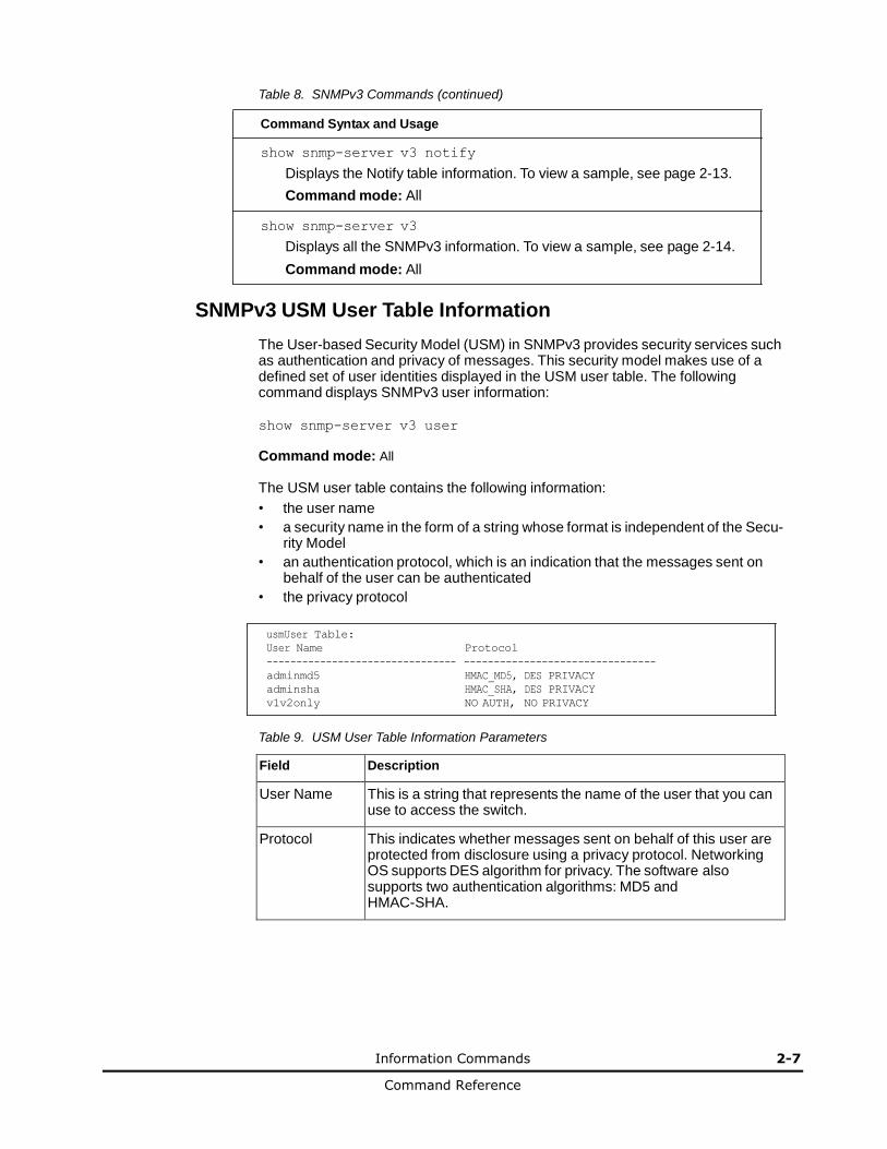
SNMPv3 USM User Table Information
The User-based Security Model (USM) in SNMPv3 provides security services such as authentication and privacy of messages. This security model makes use of a defined set of user identities displayed in the USM user table. The following command displays SNMPv3 user information:
show snmp-server v3 user
Command mode: All
The USM user table contains the following information:
• the user name
• a security name in the form of a string whose format is independent of the Secu- rity Model
• an authentication protocol, which is an indication that the messages sent on behalf of the user can be authenticated
• the privacy protocol
usmUser Table:
User Name Protocol
-------------------------------- --------------------------------
adminmd5 HMAC_MD5, DES PRIVACY
adminsha HMAC_SHA, DES PRIVACY
v1v2only NO AUTH, NO PRIVACY
Table 9. USM User Table Information Parameters
Field Description
User Name This is a string that represents the name of the user that you can use to access the switch.
Protocol This indicates whether messages sent on behalf of this user are protected from disclosure using a privacy protocol. Networking OS supports DES algorithm for privacy. The software also supports two authentication algorithms: MD5 and HMAC-SHA.

2-8 Information Commands
Command Reference
SNMPv3 View Table Information
The user can control and restrict the access allowed to a group to only a subset of the management information in the management domain that the group can access within each context by specifying the group’s rights in terms of a particular MIB view for security reasons.
The following command displays the SNMPv3 View Table:
show snmp-server v3 view
Command mode: All
View Name Subtree Mask Type
----------------- ------------------ -------------- --------
iso 1 included
v1v2only 1 included
v1v2only 1.3.6.1.6.3.15 excluded
v1v2only 1.3.6.1.6.3.16 excluded
v1v2only 1.3.6.1.6.3.18 excluded
Table 10. SNMPv3 View Table Information Parameters
Field Description
View Name Displays the name of the view.
Subtree Displays the MIB subtree as an OID string. A view subtree is the set of all MIB object instances which have a common Object Identifier prefix to their names.
Mask Displays the bit mask.
Type Displays whether a family of view subtrees is included or excluded from the MIB view.

Information Commands 2-9
Command Reference
SNMPv3 Access Table Information
The access control subsystem provides authorization services.
The vacmAccessTable maps a group name, security information, a context, and a message type, which could be the read or write type of operation or notification into a MIB view.
The View-based Access Control Model defines a set of services that an application can use for checking access rights of a group. This group's access rights are determined by a read-view, a write-view and a notify-view. The read-view represents the set of object instances authorized for the group while reading the objects. The write-view represents the set of object instances authorized for the group when writing objects. The notify-view represents the set of object instances authorized for the group when sending a notification.
The following command displays SNMPv3 access information:
show snmp-server v3 access
Command mode: All
Group Name Model Level ReadV WriteV NotifyV
---------- ------- ------ ------ ------ --------
v1v2grp snmpv1 noAuthNoPriv iso iso v1v2only
admingrp usm authPriv iso iso iso
Table 11. SNMPv3 Access Table Information
Field Description
Group Name Displays the name of group.
Model Displays the security model used, for example, SNMPv1, or SNMPv2 or USM.
Level Displays the minimum level of security required to gain rights of access. For example, noAuthNoPriv, authNoPriv, or authPriv.
ReadV Displays the MIB view to which this entry authorizes the read access.
WriteV Displays the MIB view to which this entry authorizes the write access.
NotifyV Displays the Notify view to which this entry authorizes the notify access.
2-10 Information Commands
Command Reference
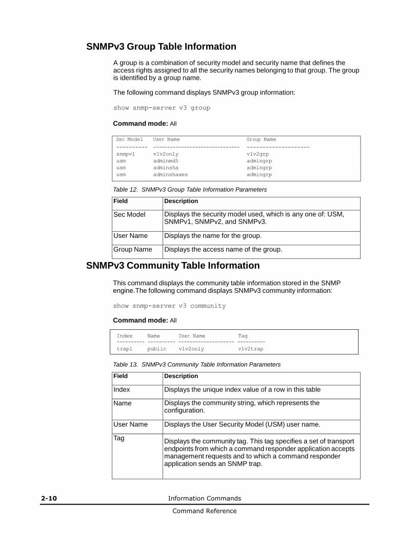
SNMPv3 Group Table Information
A group is a combination of security model and security name that defines the access rights assigned to all the security names belonging to that group. The group is identified by a group name.
The following command displays SNMPv3 group information:
show snmp-server v3 group
Command mode: All
Sec Model User Name Group Name
---------- ------------------------------- --------------------
snmpv1 v1v2only v1v2grp
usm adminmd5 admingrp
usm adminsha admingrp
usm adminshaaes admingrp
Table 12. SNMPv3 Group Table Information Parameters
Field Description
Sec Model Displays the security model used, which is any one of: USM, SNMPv1, SNMPv2, and SNMPv3.
User Name Displays the name for the group.
Group Name Displays the access name of the group.
SNMPv3 Community Table Information
This command displays the community table information stored in the SNMP engine.The following command displays SNMPv3 community information:
show snmp-server v3 community
Command mode: All
Index Name User Name Tag
---------- ---------- -------------------- ----------
trap1 public v1v2only v1v2trap
Table 13. SNMPv3 Community Table Information Parameters
Field Description
Index Displays the unique index value of a row in this table
Name Displays the community string, which represents the configuration.
User Name Displays the User Security Model (USM) user name.
Tag
Displays the community tag. This tag specifies a set of transport endpoints from which a command responder application accepts management requests and to which a command responder application sends an SNMP trap.
Information Commands 2-11
Command Reference
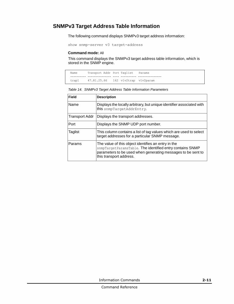
SNMPv3 Target Address Table Information
The following command displays SNMPv3 target address information:
show snmp-server v3 target-address
Command mode: All
This command displays the SNMPv3 target address table information, which is stored in the SNMP engine.
Name Transport Addr Port Taglist Params
---------- --------------- ---- ---------- ---------------
trap1 47.81.25.66 162 v1v2trap v1v2param
Table 14. SNMPv3 Target Address Table Information Parameters
Field Description
Name Displays the locally arbitrary, but unique identifier associated with this snmpTargetAddrEntry.
Transport Addr Displays the transport addresses.
Port Displays the SNMP UDP port number.
Taglist This column contains a list of tag values which are used to select target addresses for a particular SNMP message.
Params The value of this object identifies an entry in the snmpTargetParamsTable. The identified entry contains SNMP parameters to be used when generating messages to be sent to this transport address.
2-12 Information Commands
Command Reference
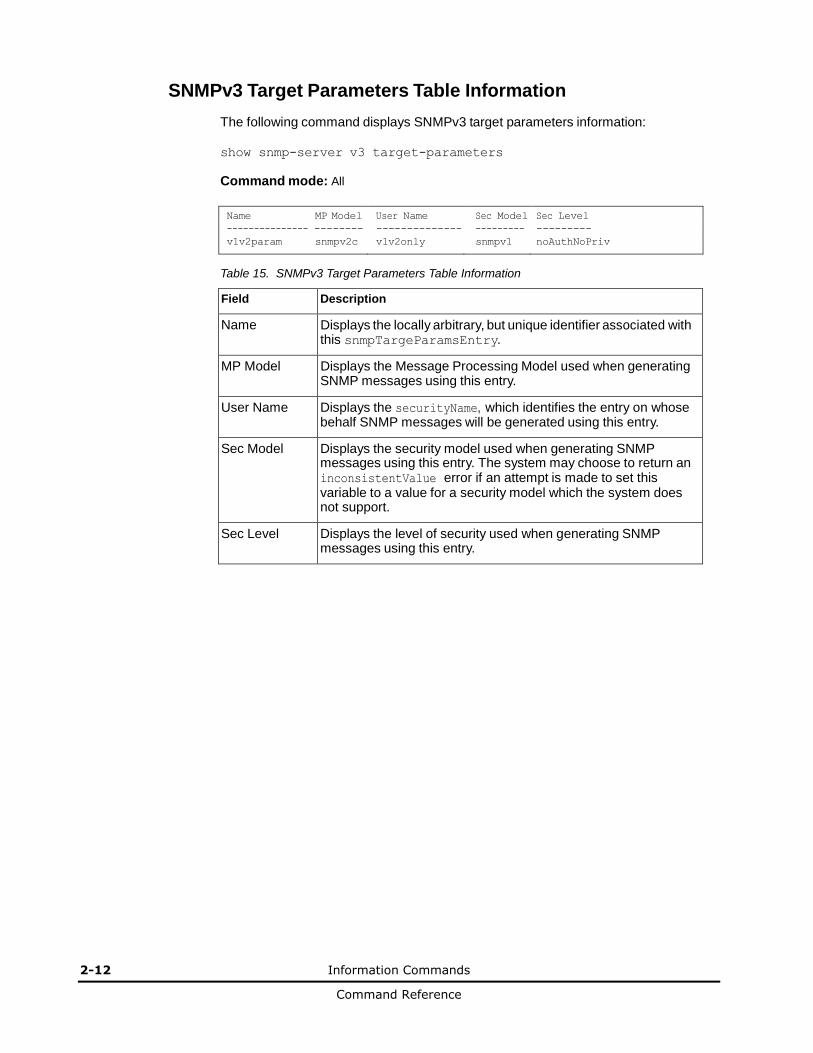
SNMPv3 Target Parameters Table Information
The following command displays SNMPv3 target parameters information:
show snmp-server v3 target-parameters
Command mode: All
Name MP Model User Name Sec Model Sec Level
--------------- -------- -------------- --------- ---------
v1v2param snmpv2c v1v2only snmpv1 noAuthNoPriv
Table 15. SNMPv3 Target Parameters Table Information
Field Description
Name Displays the locally arbitrary, but unique identifier associated with this snmpTargeParamsEntry.
MP Model Displays the Message Processing Model used when generating SNMP messages using this entry.
User Name Displays the securityName, which identifies the entry on whose behalf SNMP messages will be generated using this entry.
Sec Model Displays the security model used when generating SNMP messages using this entry. The system may choose to return an inconsistentValue error if an attempt is made to set this variable to a value for a security model which the system does not support.
Sec Level Displays the level of security used when generating SNMP messages using this entry.
Information Commands 2-13
Command Reference
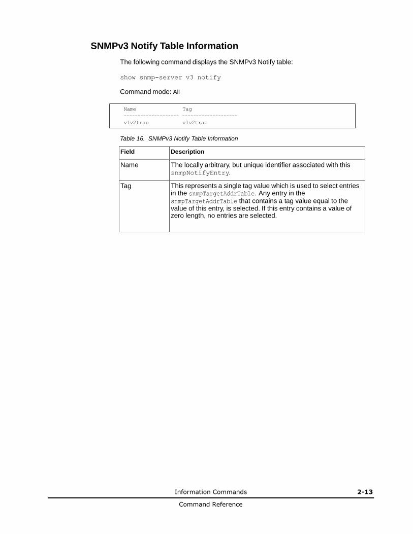
SNMPv3 Notify Table Information
The following command displays the SNMPv3 Notify table:
show snmp-server v3 notify
Command mode: All
Name Tag
-------------------- --------------------
v1v2trap v1v2trap
Table 16. SNMPv3 Notify Table Information
Field Description
Name The locally arbitrary, but unique identifier associated with this snmpNotifyEntry.
Tag This represents a single tag value which is used to select entries in the snmpTargetAddrTable. Any entry in the snmpTargetAddrTable that contains a tag value equal to the value of this entry, is selected. If this entry contains a value of zero length, no entries are selected.
2-14 Information Commands
Command Reference
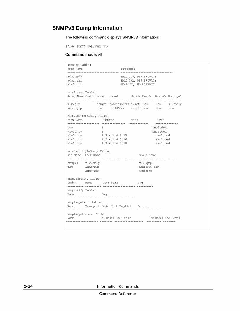
SNMPv3 Dump Information
The following command displays SNMPv3 information:
show snmp-server v3
Command mode: All
usmUser Table:
User Name Protocol
-------------------------------- --------------------------------
adminmd5 HMAC_MD5, DES PRIVACY
adminsha HMAC_SHA, DES PRIVACY
v1v2only NO AUTH, NO PRIVACY
vacmAccess Table:
Group Name Prefix Model Level Match ReadV WriteV NotifyV
---------- ------ ------- ------------ ------ ------- ------- -------
v1v2grp snmpv1 noAuthNoPriv exact iso iso v1v2only
admingrp usm authPriv exact iso iso iso
vacmViewTreeFamily Table:
View Name Subtree Mask Type
-------------------- --------------- ------------ --------------
iso 1 included
v1v2only 1 included
v1v2only 1.3.6.1.6.3.15 excluded
v1v2only 1.3.6.1.6.3.16 excluded
v1v2only 1.3.6.1.6.3.18 excluded
vacmSecurityToGroup Table:
Sec Model User Name Group Name
---------- ------------------------------- -----------------------
snmpv1 v1v2only v1v2grp
usm adminmd5 admingrp usm
adminsha admingrp
snmpCommunity Table:
Index Name User Name Tag
---------- ---------- -------------------- ----------
snmpNotify Table:
Name Tag
-------------------- --------------------
snmpTargetAddr Table:
Name Transport Addr Port Taglist Params
---------- --------------- ---- ---------- ---------------
snmpTargetParams Table:
Name MP Model User Name Sec Model Sec Level
-------------------- -------- ------------------ --------- -------
Information Commands 2-15
Command Reference
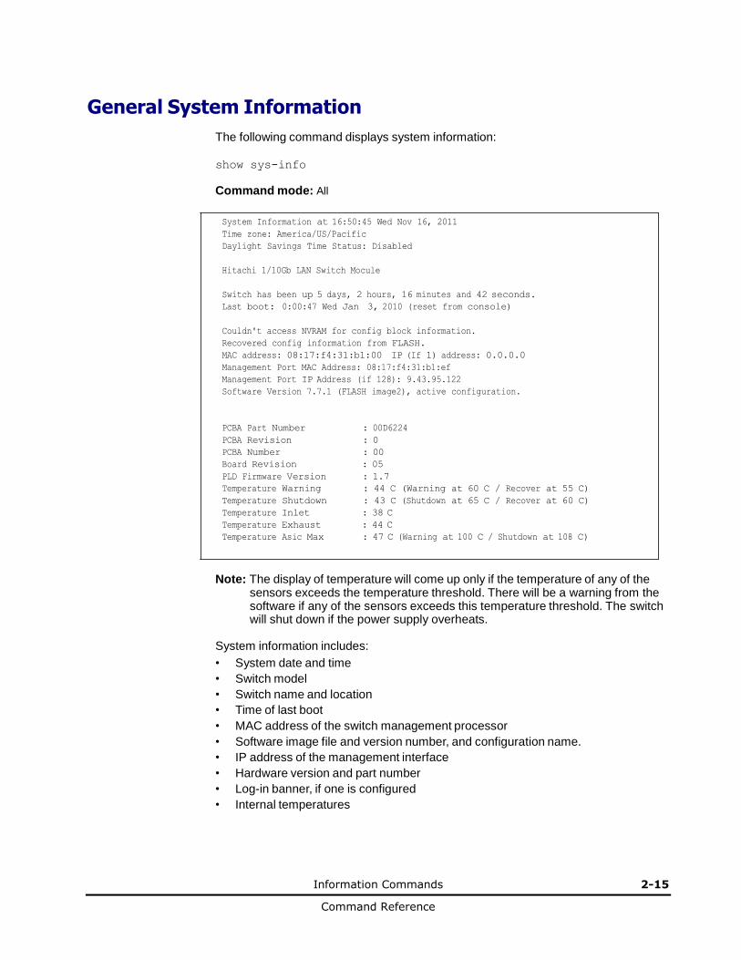
General System Information
The following command displays system information:
show sys-info
Command mode: All
System Information at 16:50:45 Wed Nov 16, 2011
Time zone: America/US/Pacific
Daylight Savings Time Status: Disabled
Hitachi 1/10Gb LAN Switch Mocule
Switch has been up 5 days, 2 hours, 16 minutes and 42 seconds.
Last boot: 0:00:47 Wed Jan 3, 2010 (reset from console)
Couldn't access NVRAM for config block information.
Recovered config information from FLASH.
MAC address: 08:17:f4:31:b1:00 IP (If 1) address: 0.0.0.0
Management Port MAC Address: 08:17:f4:31:b1:ef
Management Port IP Address (if 128): 9.43.95.122
Software Version 7.7.1 (FLASH image2), active configuration.
PCBA Part Number : 00D6224
PCBA Revision : 0
PCBA Number : 00
Board Revision : 05
PLD Firmware Version : 1.7
Temperature Warning : 44 C (Warning at 60 C / Recover at 55 C)
Temperature Shutdown : 43 C (Shutdown at 65 C / Recover at 60 C)
Temperature Inlet : 38 C
Temperature Exhaust : 44 C
Temperature Asic Max : 47 C (Warning at 100 C / Shutdown at 108 C)
Note: The display of temperature will come up only if the temperature of any of the
sensors exceeds the temperature threshold. There will be a warning from the software if any of the sensors exceeds this temperature threshold. The switch will shut down if the power supply overheats.
System information includes:
• System date and time
• Switch model
• Switch name and location
• Time of last boot
• MAC address of the switch management processor
• Software image file and version number, and configuration name.
• IP address of the management interface
• Hardware version and part number
• Log-in banner, if one is configured
• Internal temperatures
2-16 Information Commands
Command Reference
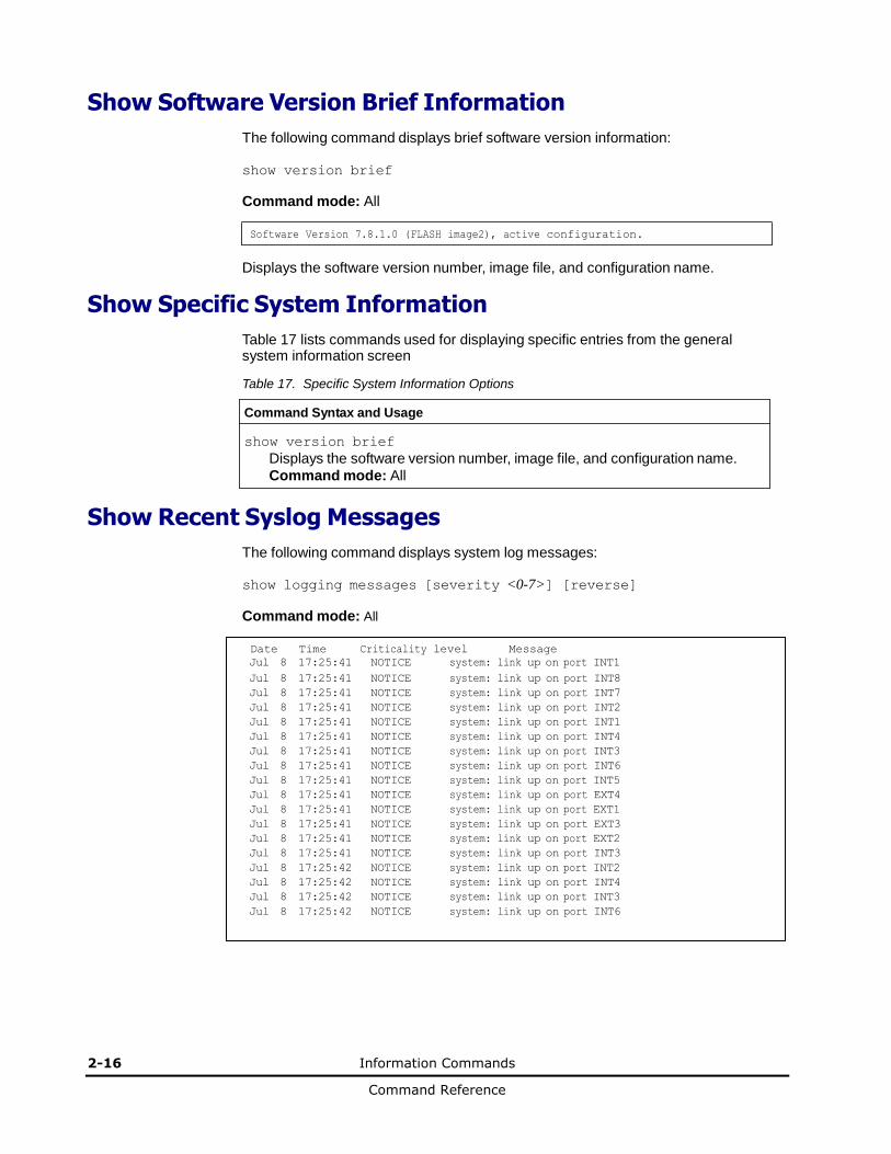
Show Software Version Brief Information
The following command displays brief software version information:
show version brief
Command mode: All
Software Version 7.8.1.0 (FLASH image2), active configuration.
Displays the software version number, image file, and configuration name.
Show Specific System Information
Table 17 lists commands used for displaying specific entries from the general system information screen
Table 17. Specific System Information Options
Command Syntax and Usage
show version brief
Displays the software version number, image file, and configuration name.
Command mode: All
Show Recent Syslog Messages
The following command displays system log messages:
show logging messages [severity <0-7>] [reverse]
Command mode: All
Date Time Criticality level Message
Jul 8 17:25:41 NOTICE system: link up on port INT1
Jul 8 17:25:41 NOTICE system: link up on port INT8
Jul 8 17:25:41 NOTICE system: link up on port INT7
Jul 8 17:25:41 NOTICE system: link up on port INT2
Jul 8 17:25:41 NOTICE system: link up on port INT1
Jul 8 17:25:41 NOTICE system: link up on port INT4
Jul 8 17:25:41 NOTICE system: link up on port INT3
Jul 8 17:25:41 NOTICE system: link up on port INT6
Jul 8 17:25:41 NOTICE system: link up on port INT5
Jul 8 17:25:41 NOTICE system: link up on port EXT4
Jul 8 17:25:41 NOTICE system: link up on port EXT1
Jul 8 17:25:41 NOTICE system: link up on port EXT3
Jul 8 17:25:41 NOTICE system: link up on port EXT2
Jul 8 17:25:41 NOTICE system: link up on port INT3
Jul 8 17:25:42 NOTICE system: link up on port INT2
Jul 8 17:25:42 NOTICE system: link up on port INT4
Jul 8 17:25:42 NOTICE system: link up on port INT3
Jul 8 17:25:42 NOTICE system: link up on port INT6
Information Commands 2-17
Command Reference
Each syslog message has a severity level associated with it, included in text form as a prefix to the log message. One of eight different prefixes is used, depending on the condition for which the administrator is being notified.
• EMERG Indicates the system is unusable
• ALERT Indicates action should be taken immediately
• CRIT Indicates critical conditions
• ERR Indicates error conditions or errored operations
• WARNING Indicates warning conditions
• NOTICE Indicates a normal but significant condition
• INFO Indicates an information message
• DEBUG Indicates a debug-level message
The severity option filters only syslog messages with a specific severity level between 0 and 7, from EMERG to DEBUG correspondingly.
The reverse option displays the output in reverse order, from the newest entry to the oldest.
2-18 Information Commands
Command Reference
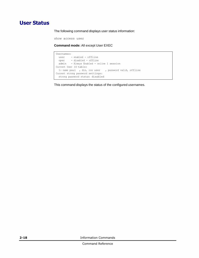
User Status
The following command displays user status information:
show access user
Command mode: All except User EXEC
Usernames:
user - enabled - offline
oper - disabled - offline
admin - Always Enabled - online 1 session
Current User ID table:
1: name paul , dis, cos user , password valid, offline
Current strong password settings:
strong password status: disabled
This command displays the status of the configured usernames.
Information Commands 2-19
Command Reference
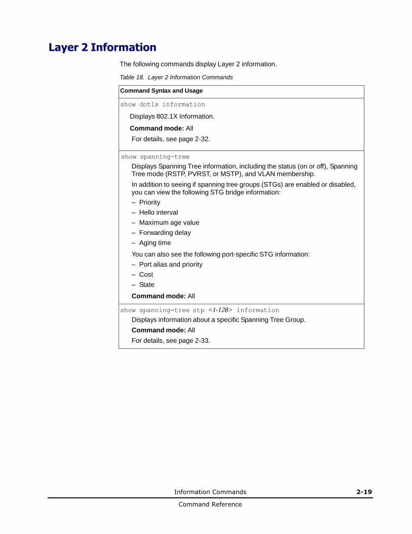
Layer 2 Information
The following commands display Layer 2 information.
Table 18. Layer 2 Information Commands
Command Syntax and Usage
show dot1x information
Displays 802.1X Information.
Command mode: All
For details, see page 2-32.
show spanning-tree
Displays Spanning Tree information, including the status (on or off), Spanning Tree mode (RSTP, PVRST, or MSTP), and VLAN membership.
In addition to seeing if spanning tree groups (STGs) are enabled or disabled, you can view the following STG bridge information:
– Priority
– Hello interval
– Maximum age value
– Forwarding delay
– Aging time
You can also see the following port-specific STG information:
– Port alias and priority
– Cost
– State
Command mode: All
show spanning-tree stp <1-128> information
Displays information about a specific Spanning Tree Group.
Command mode: All
For details, see page 2-33.

2-20 Information Commands
Command Reference
Table 18. Layer 2 Information Commands (continued)
Command Syntax and Usage
show spanning-tree mst 0 information
Displays Common Internal Spanning Tree (CIST) information for the specified instance, including the MSTP digest and VLAN membership.
CIST bridge information includes:
– Priority
– Hello interval
– Maximum age value
– Forwarding delay
– Root bridge information (priority, MAC address, path cost, root port)
CIST port information includes:
– Port number and priority
– Cost
– State
For details, see page 2-36.
Command mode: All
show spanning-tree mst configuration
Displays the current MSTP settings.
show portchannel information
Displays the state of each port in the various static or LACP trunk groups. For details, see page 2-38.
Command mode: All
show vlan
Displays VLAN configuration information for all configured VLANs, including:
– VLAN Number
– VLAN Name
– Status
– Port membership of the VLAN
For details, see page 2-39.
Command mode: All
show failover trigger <trigger number>
Displays Layer 2 Failover information. For details, see page 2-25.
Command mode: All
Information Commands 2-21
Command Reference
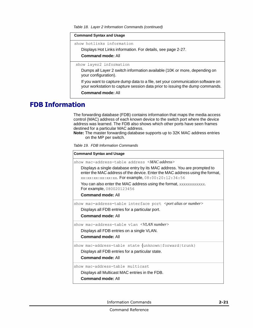
Table 18. Layer 2 Information Commands (continued)
Command Syntax and Usage
show hotlinks information
Displays Hot Links information. For details, see page 2-27.
Command mode: All
show layer2 information
Dumps all Layer 2 switch information available (10K or more, depending on your configuration).
If you want to capture dump data to a file, set your communication software on your workstation to capture session data prior to issuing the dump commands.
Command mode: All
FDB Information
The forwarding database (FDB) contains information that maps the media access control (MAC) address of each known device to the switch port where the device address was learned. The FDB also shows which other ports have seen frames destined for a particular MAC address. Note: The master forwarding database supports up to 32K MAC address entries
on the MP per switch.
Table 19. FDB Information Commands
Command Syntax and Usage
show mac-address-table address <MAC address>
Displays a single database entry by its MAC address. You are prompted to enter the MAC address of the device. Enter the MAC address using the format,
xx:xx:xx:xx:xx:xx. For example, 08:00:20:12:34:56
You can also enter the MAC address using the format, xxxxxxxxxxxx. For example, 080020123456
Command mode: All
show mac-address-table interface port <port alias or number>
Displays all FDB entries for a particular port.
Command mode: All
show mac-address-table vlan <VLAN number>
Displays all FDB entries on a single VLAN.
Command mode: All
show mac-address-table state {unknown|forward|trunk}
Displays all FDB entries for a particular state.
Command mode: All
show mac-address-table multicast
Displays all Multicast MAC entries in the FDB.
Command mode: All
2-22 Information Commands
Command Reference
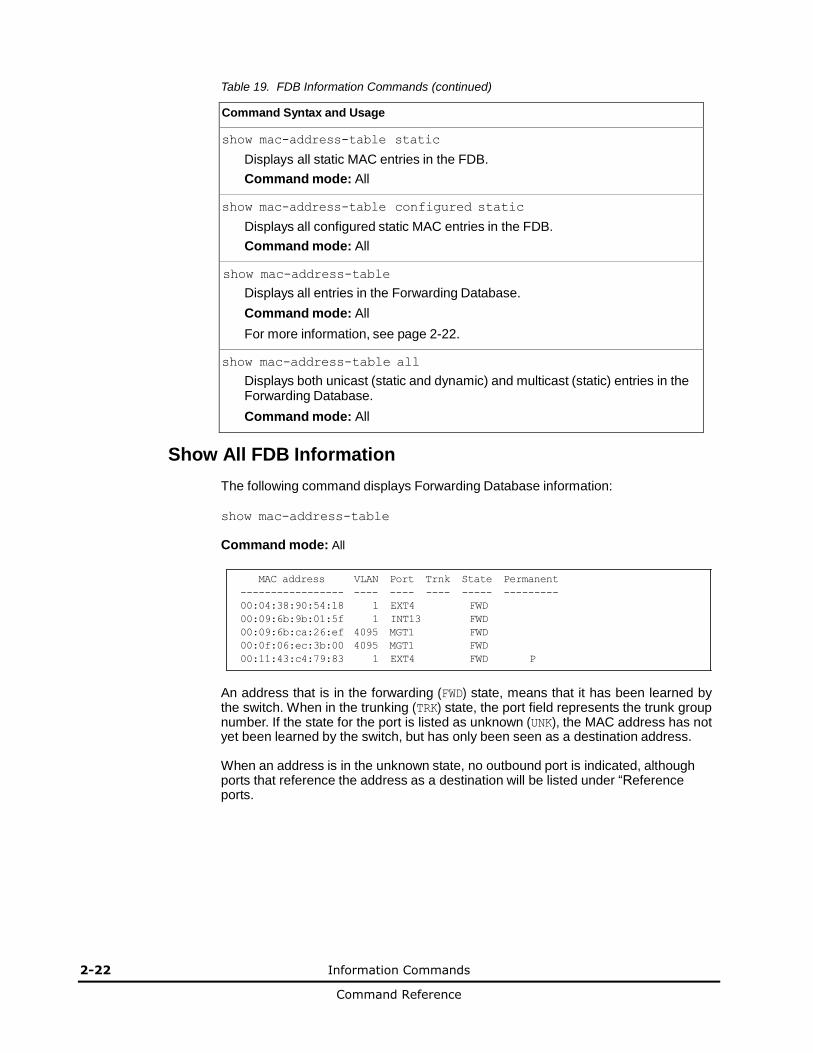
Table 19. FDB Information Commands (continued)
Command Syntax and Usage
show mac-address-table static
Displays all static MAC entries in the FDB.
Command mode: All
show mac-address-table configured static
Displays all configured static MAC entries in the FDB.
Command mode: All
show mac-address-table
Displays all entries in the Forwarding Database.
Command mode: All
For more information, see page 2-22.
show mac-address-table all
Displays both unicast (static and dynamic) and multicast (static) entries in the Forwarding Database.
Command mode: All
Show All FDB Information
The following command displays Forwarding Database information:
show mac-address-table
Command mode: All
MAC address VLAN Port Trnk State Permanent
----------------- ---- ---- ---- ----- ---------
00:04:38:90:54:18 1 EXT4 FWD
00:09:6b:9b:01:5f 1 INT13 FWD
00:09:6b:ca:26:ef 4095 MGT1 FWD
00:0f:06:ec:3b:00 4095 MGT1 FWD
00:11:43:c4:79:83 1 EXT4 FWD P
An address that is in the forwarding (FWD) state, means that it has been learned by the switch. When in the trunking (TRK) state, the port field represents the trunk group number. If the state for the port is listed as unknown (UNK), the MAC address has not yet been learned by the switch, but has only been seen as a destination address.
When an address is in the unknown state, no outbound port is indicated, although ports that reference the address as a destination will be listed under “Reference ports.
Information Commands 2-23
Command Reference
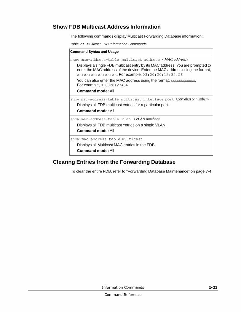
Show FDB Multicast Address Information
The following commands display Multicast Forwarding Database information:.
Table 20. Multicast FDB Information Commands
Command Syntax and Usage
show mac-address-table multicast address <MAC address>
Displays a single FDB multicast entry by its MAC address. You are prompted to enter the MAC address of the device. Enter the MAC address using the format,
xx:xx:xx:xx:xx:xx. For example, 03:00:20:12:34:56
You can also enter the MAC address using the format, xxxxxxxxxxxx. For example, 030020123456
Command mode: All
show mac-address-table multicast interface port <port alias or number>
Displays all FDB multicast entries for a particular port.
Command mode: All
show mac-address-table vlan <VLAN number>
Displays all FDB multicast entries on a single VLAN.
Command mode: All
show mac-address-table multicast
Displays all Multicast MAC entries in the FDB.
Command mode: All
Clearing Entries from the Forwarding Database
To clear the entire FDB, refer to “Forwarding Database Maintenance” on page 7-4.
2-24 Information Commands
Command Reference
Link Aggregation Control Protocol Information
Use these commands to display LACP status information about each port on 1/10Gb LAN Switch Module.
Table 21. LACP Information Commands
Command Syntax and Usage
show lacp aggregator <aggregator ID>
Displays detailed information about the LACP aggregator.
Command mode: All
show interface port <port alias or number> lacp information
Displays LACP information about the selected port.
Command mode: All
show lacp information
Displays a summary of LACP information.
Command mode: All
For details, see page 2-24.
Link Aggregation Control Protocol
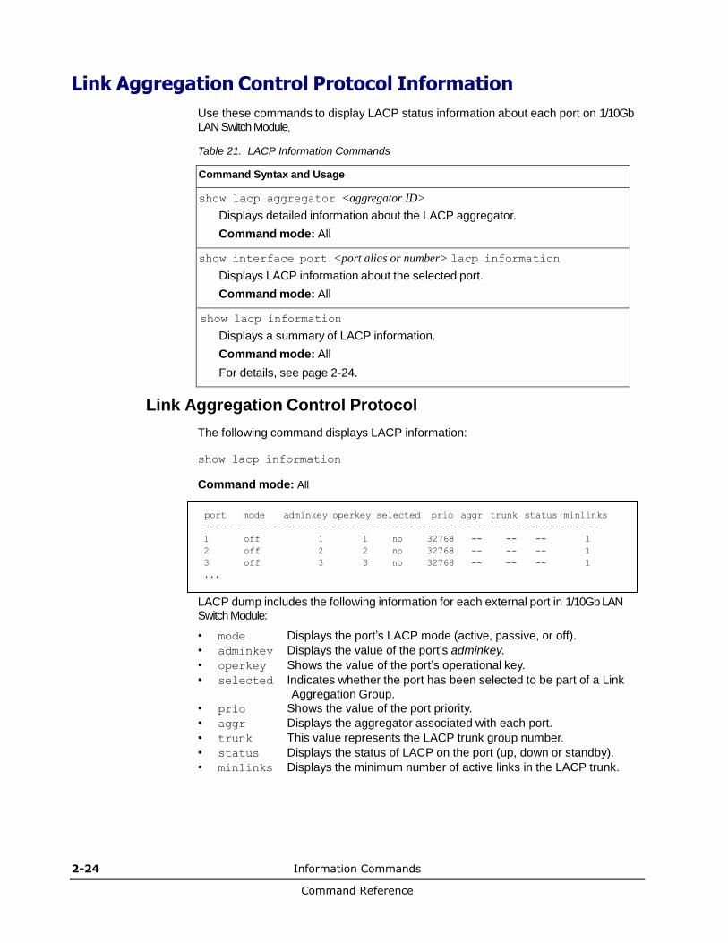
The following command displays LACP information:
show lacp information
Command mode: All
port mode adminkey operkey selected prio aggr trunk status minlinks
---------------------------------------------------------------------------------
1 off 1 1 no 32768 -- -- -- 1
2 off 2 2 no 32768 -- -- -- 1
3 off 3 3 no 32768 -- -- -- 1
...
LACP dump includes the following information for each external port in 1/10Gb LAN Switch Module:
• mode Displays the port’s LACP mode (active, passive, or off).
• adminkey Displays the value of the port’s adminkey.
• operkey Shows the value of the port’s operational key.
• selected Indicates whether the port has been selected to be part of a Link
Aggregation Group.
• prio Shows the value of the port priority.
• aggr Displays the aggregator associated with each port.
• trunk This value represents the LACP trunk group number.
• status Displays the status of LACP on the port (up, down or standby).
• minlinks Displays the minimum number of active links in the LACP trunk.
Information Commands 2-25
Command Reference
Layer 2 Failover Information Commands
Table 22. Layer 2 Failover Information Commands
Command Syntax and Usage
show failover trigger <trigger number>
Displays detailed information about the selected Layer 2 Failover trigger.
Command mode: All
show failover trigger
Displays a summary of Layer 2 Failover information. For details, see page 2-25.
Command mode: All
Layer 2 Failover Information
The following command displays Layer 2 Failover information:
show failover trigger
2-26 Information Commands
Command Reference
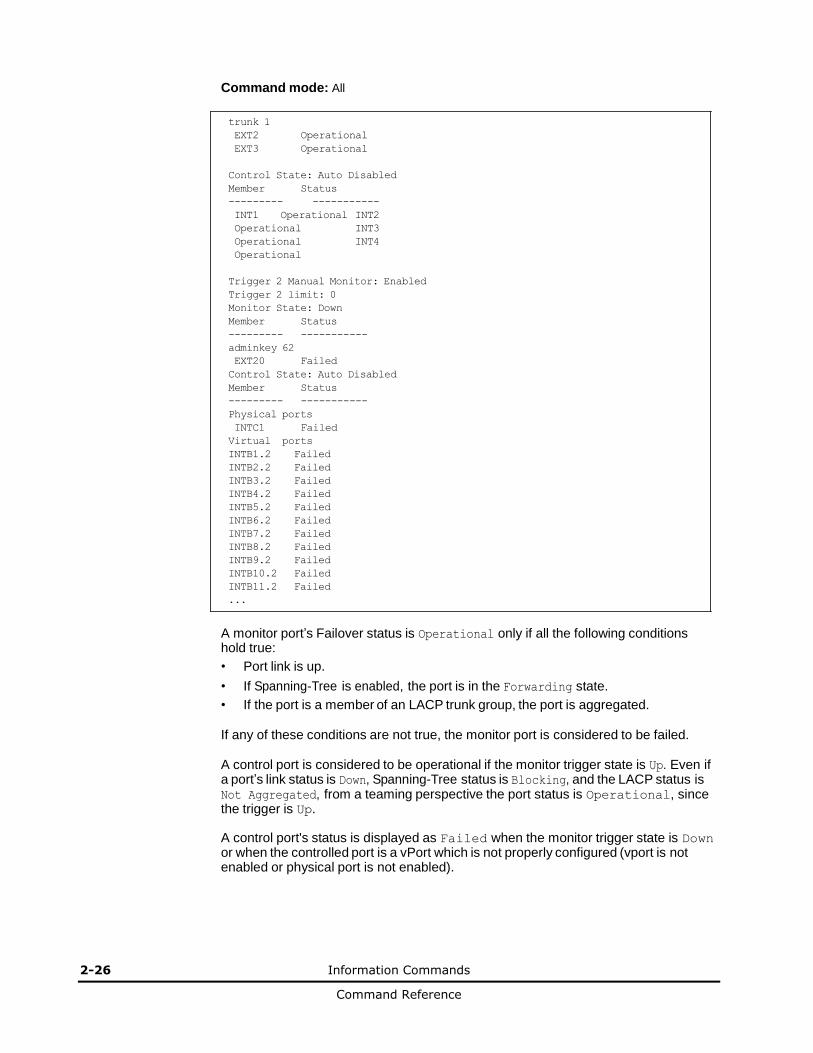
Command mode: All
trunk 1
EXT2 Operational
EXT3 Operational
Control State: Auto Disabled
Member Status
--------- -----------
INT1 Operational INT2
Operational INT3
Operational INT4
Operational
Trigger 2 Manual Monitor: Enabled
Trigger 2 limit: 0
Monitor State: Down
Member Status
--------- -----------
adminkey 62
EXT20 Failed
Control State: Auto Disabled
Member Status
--------- -----------
Physical ports
INTC1 Failed
Virtual ports
INTB1.2 Failed
INTB2.2 Failed
INTB3.2 Failed
INTB4.2 Failed
INTB5.2 Failed
INTB6.2 Failed
INTB7.2 Failed
INTB8.2 Failed
INTB9.2 Failed
INTB10.2 Failed
INTB11.2 Failed
...
A monitor port’s Failover status is Operational only if all the following conditions hold true:
• Port link is up.
• If Spanning-Tree is enabled, the port is in the Forwarding state.
• If the port is a member of an LACP trunk group, the port is aggregated.
If any of these conditions are not true, the monitor port is considered to be failed.
A control port is considered to be operational if the monitor trigger state is Up. Even if a port’s link status is Down, Spanning-Tree status is Blocking, and the LACP status is Not Aggregated, from a teaming perspective the port status is Operational, since the trigger is Up.
A control port's status is displayed as Failed when the monitor trigger state is Down or when the controlled port is a vPort which is not properly configured (vport is not enabled or physical port is not enabled).
Information Commands 2-27
Command Reference
Hot Links Information
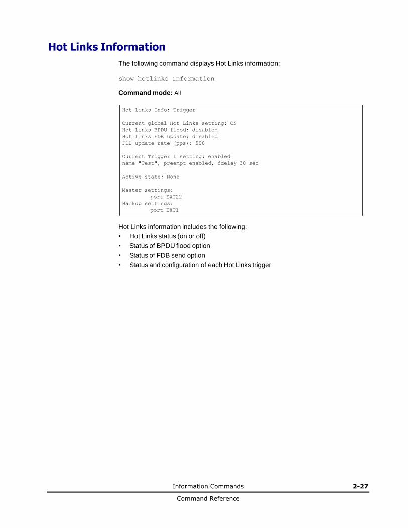
The following command displays Hot Links information:
show hotlinks information
Command mode: All
Hot Links Info: Trigger
Current global Hot Links setting: ON
Hot Links BPDU flood: disabled
Hot Links FDB update: disabled
FDB update rate (pps): 500
Current Trigger 1 setting: enabled
name "Test", preempt enabled, fdelay 30 sec
Active state: None
Master settings:
port EXT22
Backup settings:
port EXT1
Hot Links information includes the following:
• Hot Links status (on or off)
• Status of BPDU flood option
• Status of FDB send option
• Status and configuration of each Hot Links trigger
2-28 Information Commands
Command Reference
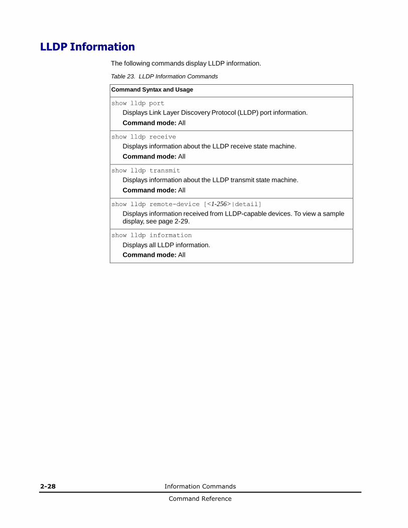
LLDP Information
The following commands display LLDP information.
Table 23. LLDP Information Commands
Command Syntax and Usage
show lldp port
Displays Link Layer Discovery Protocol (LLDP) port information.
Command mode: All
show lldp receive
Displays information about the LLDP receive state machine.
Command mode: All
show lldp transmit
Displays information about the LLDP transmit state machine.
Command mode: All
show lldp remote-device [<1-256>|detail]
Displays information received from LLDP-capable devices. To view a sample display, see page 2-29.
show lldp information
Displays all LLDP information.
Command mode: All
Information Commands 2-29
Command Reference
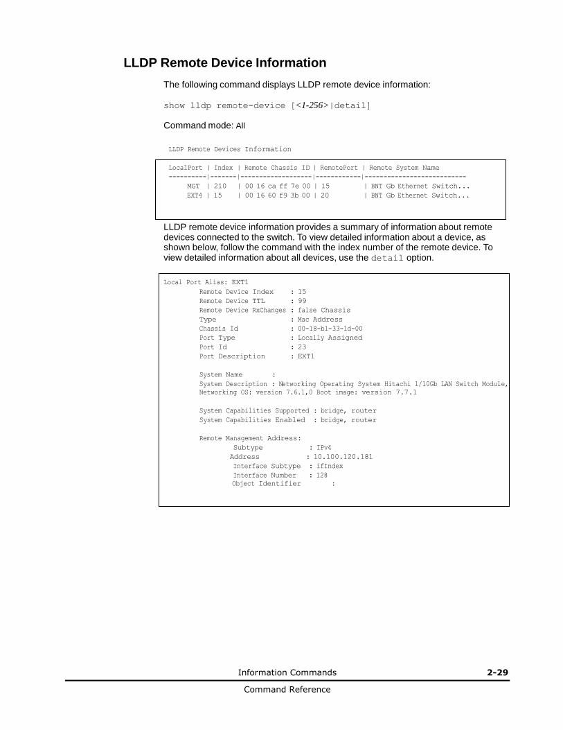
LLDP Remote Device Information
The following command displays LLDP remote device information:
show lldp remote-device [<1-256>|detail]
Command mode: All
LLDP Remote Devices Information
LocalPort | Index | Remote Chassis ID | RemotePort | Remote System Name
----------|-------|-------------------|------------|---------------------------
MGT | 210 | 00 16 ca ff 7e 00 | 15 | BNT Gb Ethernet Switch...
EXT4 | 15 | 00 16 60 f9 3b 00 | 20 | BNT Gb Ethernet Switch...
LLDP remote device information provides a summary of information about remote devices connected to the switch. To view detailed information about a device, as shown below, follow the command with the index number of the remote device. To view detailed information about all devices, use the detail option.
Local Port Alias: EXT1
Remote Device Index : 15
Remote Device TTL : 99
Remote Device RxChanges : false Chassis
Type : Mac Address
Chassis Id : 00-18-b1-33-1d-00
Port Type : Locally Assigned
Port Id : 23
Port Description : EXT1
System Name :
System Description : Networking Operating System Hitachi 1/10Gb LAN Switch Module,
Networking OS: version 7.6.1,0 Boot image: version 7.7.1
System Capabilities Supported : bridge, router
System Capabilities Enabled : bridge, router
Remote Management Address:
Subtype : IPv4
Address : 10.100.120.181
Interface Subtype : ifIndex
Interface Number : 128
Object Identifier :
2-30 Information Commands
Command Reference
Unidirectional Link Detection Information
The following commands show unidirectional link detection information.
Table 24. UDLD Information Commands
Command Syntax and Usage
show interface port <port alias or number> udld
Displays UDLD information about the selected port.
Command mode: All
show udld
Displays all UDLD information.
Command mode: All
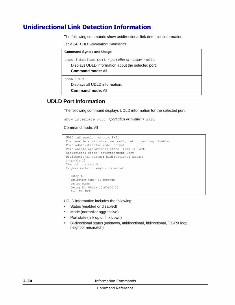
UDLD Port Information
The following command displays UDLD information for the selected port:
show interface port <port alias or number> udld
Command mode: All
UDLD information on port EXT1
Port enable administrative configuration setting: Enabled
Port administrative mode: normal
Port enable operational state: link up Port
operational state: advertisement Port
bidirectional status: bidirectional Message
interval: 15
Time out interval: 5
Neighbor cache: 1 neighbor detected
Entry #1
Expiration time: 31 seconds
Device Name:
Device ID: 00:da:c0:00:04:00
Port ID: EXT1
UDLD information includes the following:
• Status (enabled or disabled)
• Mode (normal or aggressive)
• Port state (link up or link down)
• Bi-directional status (unknown, unidirectional, bidirectional, TX-RX loop, neighbor mismatch)

Information Commands 2-31
Command Reference
OAM Discovery Information
Table 25. OAM Discovery Information Commands
Command Syntax and Usage
show interface port <port alias or number> oam
Displays OAM information about the selected port.
Command mode: All
show oam
Displays all OAM information.
Command mode: All
OAM Port Information
The following command displays OAM information for the selected port:
show interface port <port alias or number> oam
Command mode: All
OAM information on port EXT1
State enabled
Mode active
Link up
Satisfied Yes
Evaluating No
Remote port information:
Mode active
MAC address 00:da:c0:00:04:00
Stable Yes
State valid Yes
Evaluating No
OAM port display shows information about the selected port and the peer to which the link is connected.
2-32 Information Commands
Command Reference
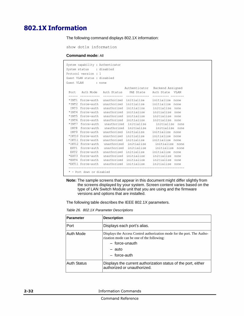
802.1X Information
The following command displays 802.1X information:
show dot1x information
Command mode: All
System capability : Authenticator
System status : disabled
Protocol version : 1
Guest VLAN status : disabled
Guest VLAN : none
Authenticator Backend Assigned
Port Auth Mode Auth Status PAE State Auth State VLAN
----- ------------ ------------ -------------- ---------- --------
*INT1 force-auth unauthorized initialize initialize none
*INT2 force-auth unauthorized initialize initialize none
INT3 force-auth unauthorized initialize initialize none
*INT4 force-auth unauthorized initialize initialize none
*INT5 force-auth unauthorized initialize initialize none
*INT6 force-auth unauthorized initialize initialize none
*INT7 force-auth unauthorized initialize initialize none
INT8 force-auth unauthorized initialize initialize none
INT9 force-auth unauthorized initialize initialize none
*INT10 force-auth unauthorized initialize initialize none
*INT11 force-auth unauthorized initialize initialize none
*INT12 force-auth unauthorized initialize initialize none
EXT1 force-auth unauthorized initialize initialize none
EXT2 force-auth unauthorized initialize initialize none
*EXT3 force-auth unauthorized initialize initialize none
*EXT4 force-auth unauthorized initialize initialize none
*EXT11 force-auth unauthorized initialize initialize none
----------------------------------------------------------------------
* - Port down or disabled
Note: The sample screens that appear in this document might differ slightly from the screens displayed by your system. Screen content varies based on the type of LAN Switch Module unit that you are using and the firmware versions and options that are installed.
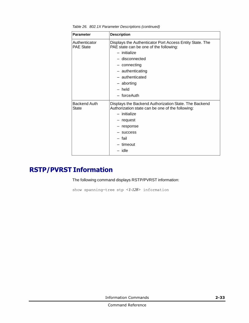
The following table describes the IEEE 802.1X parameters.
Table 26. 802.1X Parameter Descriptions
Parameter Description
Port Displays each port’s alias.
Auth Mode Displays the Access Control authorization mode for the port. The Autho-
rization mode can be one of the following:
– force-unauth
– auto
– force-auth
Auth Status Displays the current authorization status of the port, either authorized or unauthorized.
Information Commands 2-33
Command Reference
Table 26. 802.1X Parameter Descriptions (continued)
Parameter Description
Authenticator PAE State
Displays the Authenticator Port Access Entity State. The PAE state can be one of the following:
– initialize
– disconnected
– connecting
– authenticating
– authenticated
– aborting
– held
– forceAuth
Backend Auth State
Displays the Backend Authorization State. The Backend Authorization state can be one of the following:
– initialize
– request
– response
– success
– fail
– timeout
– idle
RSTP/PVRST Information
The following command displays RSTP/PVRST information:
show spanning-tree stp <1-128> information

2-34 Information Commands
Command Reference
Command mode: All
Spanning Tree Group 1: On (RSTP)
VLANs: 1
Current Root: Path-Cost Port Hello MaxAge FwdDel
ffff 00:13:0a:4f:7d:d0 0 EXT4 2 20 15
Parameters: Priority Hello MaxAge FwdDel Aging
61440 2 20 15 300
Port Prio Cost State Role Designated Bridge Des Port Type
----- ---- --------- ----- ---- ---------------------- -------- -----
INT1 0 0 DSB * INT2 0 0 DSB * INT3 0 0 FWD * INT4 0 0 DSB * INT5 0 0 DSB * INT6 0 0 DSB * INT7 0 0 DSB * INT8 0 0 DSB * INT9 0 0 DSB * INT10 0 0 DSB * INT11 0 0 DSB * INT12 0 0 DSB * INT13 0 0 DSB * INT14 0 0 DSB * EXT1 128 2000 FWD DESG 8000-00:11:58:ae:39:00 8011 P2P
EXT2 128 2000 DISC BKUP 8000-00:11:58:ae:39:00 8011 P2P
EXT3 128 2000 FWD DESG 8000-00:11:58:ae:39:00 8013 P2P
EXT4 128 20000 DISC BKUP 8000-00:11:58:ae:39:00 8013 Shared
... * = STP turned off for this port.
Note: The sample screens that appear in this document might differ slightly from
the screens displayed by your system. Screen content varies based on the type of BladeSymphony unit that you are using and the firmware versions and options that are installed.
You can configure the switch software to use the IEEE 802.1D (2004) Rapid Spanning Tree Protocol (RSTP), Per VLAN Rapid Spanning Tree Protocol (PVRST) or IEEE 802.1Q (2003) Multiple Spanning Tree Protocol (MSTP).
If RSTP/PVRST is turned on, you can view the following bridge information for the Spanning Tree Group:.
Table 27. RSTP/PVRST Bridge Parameter Descriptions
Parameter Description
Current Root The Current Root shows information about the root bridge for the Spanning Tree. Information includes the priority (in hexadecimal notation) and the MAC address of the root.
Priority (bridge) The Bridge Priority parameter controls which bridge on the network will become the STP root bridge.
Hello The Hello Time parameter specifies, in seconds, how often the root bridge transmits a configuration bridge protocol data unit (BPDU). Any bridge that is not the root bridge uses the root bridge hello value.
Information Commands 2-35
Command Reference
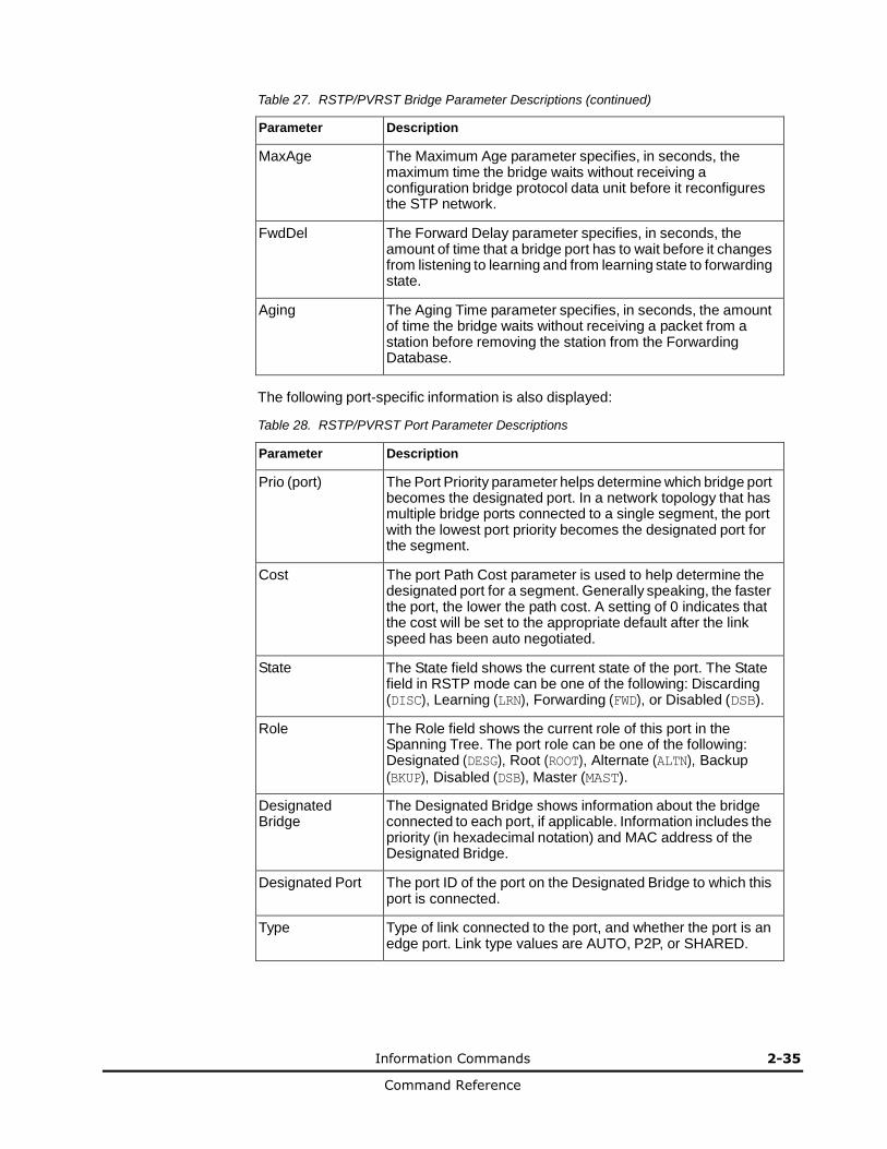
Table 27. RSTP/PVRST Bridge Parameter Descriptions (continued)
Parameter Description
MaxAge The Maximum Age parameter specifies, in seconds, the maximum time the bridge waits without receiving a configuration bridge protocol data unit before it reconfigures the STP network.
FwdDel The Forward Delay parameter specifies, in seconds, the amount of time that a bridge port has to wait before it changes from listening to learning and from learning state to forwarding state.
Aging The Aging Time parameter specifies, in seconds, the amount of time the bridge waits without receiving a packet from a station before removing the station from the Forwarding Database.
The following port-specific information is also displayed:
Table 28. RSTP/PVRST Port Parameter Descriptions
Parameter Description
Prio (port) The Port Priority parameter helps determine which bridge port becomes the designated port. In a network topology that has multiple bridge ports connected to a single segment, the port with the lowest port priority becomes the designated port for the segment.
Cost The port Path Cost parameter is used to help determine the designated port for a segment. Generally speaking, the faster the port, the lower the path cost. A setting of 0 indicates that the cost will be set to the appropriate default after the link speed has been auto negotiated.
State The State field shows the current state of the port. The State field in RSTP mode can be one of the following: Discarding (DISC), Learning (LRN), Forwarding (FWD), or Disabled (DSB).
Role The Role field shows the current role of this port in the Spanning Tree. The port role can be one of the following: Designated (DESG), Root (ROOT), Alternate (ALTN), Backup (BKUP), Disabled (DSB), Master (MAST).
Designated Bridge
The Designated Bridge shows information about the bridge connected to each port, if applicable. Information includes the priority (in hexadecimal notation) and MAC address of the Designated Bridge.
Designated Port The port ID of the port on the Designated Bridge to which this port is connected.
Type Type of link connected to the port, and whether the port is an edge port. Link type values are AUTO, P2P, or SHARED.

2-36 Information Commands
Command Reference
Common Internal Spanning Tree Information
The following command displays Common Internal Spanning Tree (CIST) information:
show spanning-tree mst 0 information
Command mode: All
Mstp Digest: 0xac36177f50283cd4b83821d8ab26de62
Common Internal Spanning Tree:
VLANs MAPPED: 1-4094
VLANs: 1 2 4095
Current Root: Path-Cost Port MaxAge FwdDel
8000 00:11:58:ae:39:00 2026 0 20 15
Cist Regional Root: Path-Cost
8000 00:11:58:ae:39:00 0
Parameters: Priority MaxAge FwdDel Hops
32768 20 15 20
Port Prio Cost State Role Designated Bridge Des Port Hello Type
----- ---- --------- ----- ---- ---------------------- -------- ----- ----
1 128 2000! FWD ROOT fffe-00:13:0a:4f:7d:d0 8011 2 P2P#
23 128 2000! DISC ALTN fffe-00:22:00:24:46:00 8012 2 P2P#
MGT 0 0 FWD *
* = STP turned off for this port.
! = Automatic path cost.
# = PVST Protection enabled for this port.
In addition to seeing if Common Internal Spanning Tree (CIST) is enabled or disabled, you can view the following CIST bridge information:
Table 29. CIST Parameter Descriptions
Parameter Description
CIST Root The CIST Root shows information about the root bridge for the Common Internal Spanning Tree (CIST). Values on this row of information refer to the CIST root.
CIST Regional Root
The CIST Regional Root shows information about the root bridge for this MSTP region. Values on this row of information refer to the regional root.
Priority (bridge) The bridge priority parameter controls which bridge on the network will become the STP root bridge.
Hello The hello time parameter specifies, in seconds, how often the root bridge transmits a configuration bridge protocol data unit (BPDU). Any bridge that is not the root bridge uses the root bridge hello value.

Information Commands 2-37
Command Reference
Table 29. CIST Parameter Descriptions (continued)
Parameter Description
MaxAge The maximum age parameter specifies, in seconds, the maximum time the bridge waits without receiving a configuration bridge protocol data unit before it reconfigure the STP network.
FwdDel The forward delay parameter specifies, in seconds, the amount of time that a bridge port has to wait before it changes from learning state to forwarding state.
Hops The maximum number of bridge hops a packet can traverse before it is dropped. The default value is 20.
The following port-specific CIST information is also displayed:
Table 30. CIST Parameter Descriptions
Parameter Description
Prio (port) The port priority parameter helps determine which bridge port becomes the designated port. In a network topology that has multiple bridge ports connected to a single segment, the port with the lowest port priority becomes the designated port for the segment.
Cost The port path cost parameter is used to help determine the designated port for a segment. Generally speaking, the faster the port, the lower the path cost. A setting of 0 indicates that the cost will be set to the appropriate default after the link speed has been auto negotiated.
State The state field shows the current state of the port. The state field can be either Discarding (DISC), Learning (LRN), or Forwarding (FWD).
Role The Role field shows the current role of this port in the Spanning Tree. The port role can be one of the following: Designated (DESG), Root (ROOT), Alternate (ALTN), Backup (BKUP), Disabled (DSB), Master (MAST), or Unknown (UNK).
Designated Bridge
The Designated Bridge shows information about the bridge connected to each port, if applicable. Information includes the priority (in hexadecimal notation) and MAC address of the Designated Bridge.
Designated Port The port ID of the port on the Designated Bridge to which this port is connected.
Type Type of link connected to the port, and whether the port is an edge port. Link type values are AUTO, P2P, or SHARED.
2-38 Information Commands
Command Reference
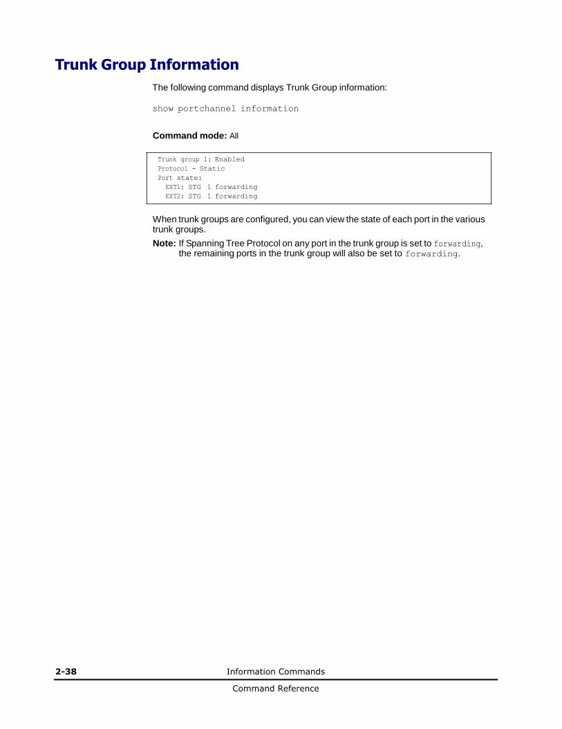
Trunk Group Information
The following command displays Trunk Group information:
show portchannel information
Command mode: All
Trunk group 1: Enabled
Protocol - Static
Port state:
EXT1: STG 1 forwarding
EXT2: STG 1 forwarding
When trunk groups are configured, you can view the state of each port in the various trunk groups.
Note: If Spanning Tree Protocol on any port in the trunk group is set to forwarding, the remaining ports in the trunk group will also be set to forwarding.
Information Commands 2-39
Command Reference
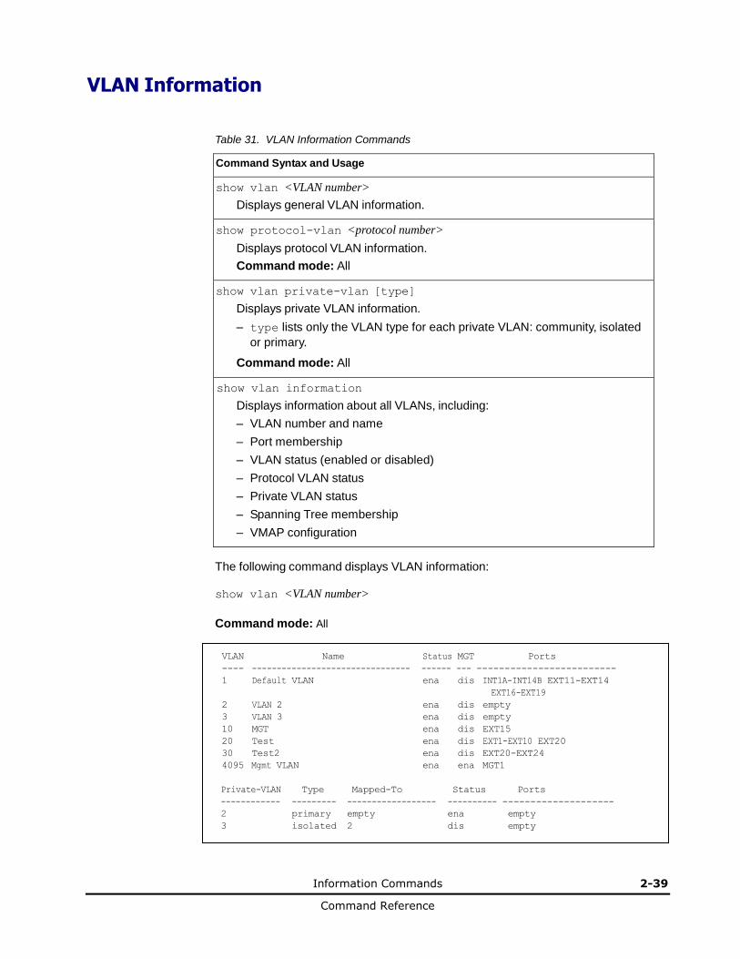
VLAN Information
Table 31. VLAN Information Commands
Command Syntax and Usage
show vlan <VLAN number>
Displays general VLAN information.
show protocol-vlan <protocol number>
Displays protocol VLAN information.
Command mode: All
show vlan private-vlan [type]
Displays private VLAN information.
– type lists only the VLAN type for each private VLAN: community, isolated
or primary.
Command mode: All
show vlan information
Displays information about all VLANs, including:
– VLAN number and name
– Port membership
– VLAN status (enabled or disabled)
– Protocol VLAN status
– Private VLAN status
– Spanning Tree membership
– VMAP configuration
The following command displays VLAN information:
show vlan <VLAN number>
Command mode: All
VLAN Name Status MGT Ports
---- -------------------------------- ------ --- -------------------------
1 Default VLAN ena dis INT1A-INT14B EXT11-EXT14
EXT16-EXT19
2 VLAN 2 ena dis empty
3 VLAN 3 ena dis empty
10 MGT ena dis EXT15
20 Test ena dis EXT1-EXT10 EXT20
30 Test2 ena dis EXT20-EXT24
4095 Mgmt VLAN ena ena MGT1
Private-VLAN Type Mapped-To Status Ports
------------ --------- ------------------ ---------- --------------------
2 primary empty ena empty
3 isolated 2 dis empty

2-40 Information Commands
Command Reference
Note: The sample screens that appear in this document might differ slightly from the screens displayed by your system. Screen content varies based on the type of LAN Switch Module unit that you are using and the firmware versions and options that are installed.
This information display includes all configured VLANs and all member ports that have an active link state. Port membership is represented in slot/port format.
VLAN information includes:
• VLAN Number
• VLAN Type
• Status
• Management status of the VLAN
• Port membership of the VLAN
• Protocol-based VLAN information
• Private VLAN configuration
Information Commands 2-41
Command Reference
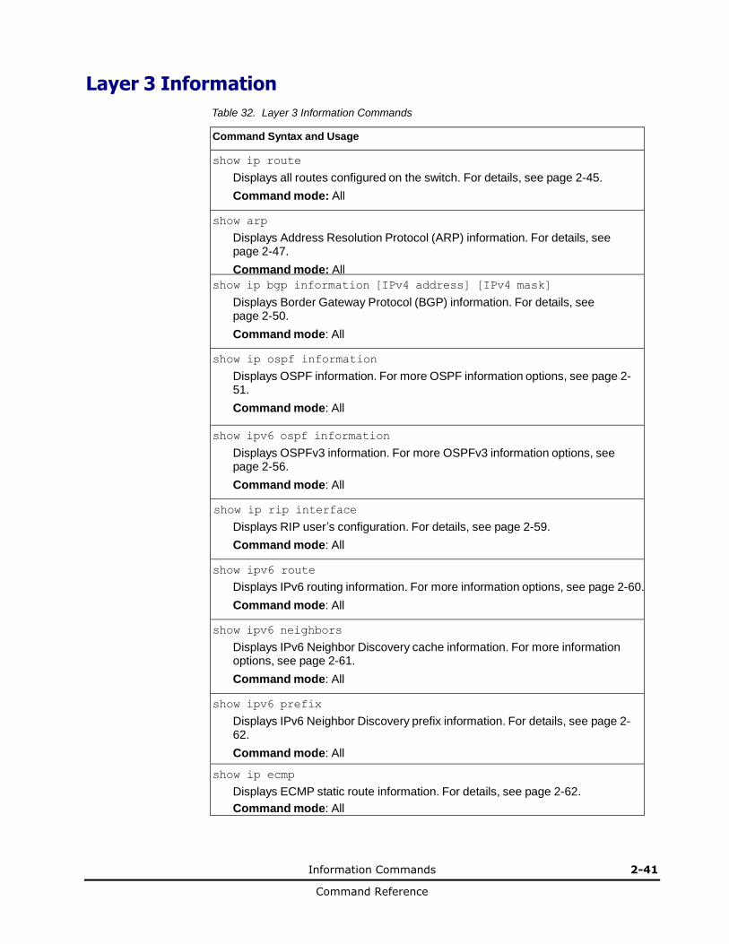
Layer 3 Information
Table 32. Layer 3 Information Commands
Command Syntax and Usage
show ip route
Displays all routes configured on the switch. For details, see page 2-45.
Command mode: All
show arp
Displays Address Resolution Protocol (ARP) information. For details, see page 2-47.
Command mode: All
show ip bgp information [IPv4 address] [IPv4 mask]
Displays Border Gateway Protocol (BGP) information. For details, see page 2-50.
Command mode: All
show ip ospf information
Displays OSPF information. For more OSPF information options, see page 2-51.
Command mode: All
show ipv6 ospf information
Displays OSPFv3 information. For more OSPFv3 information options, see page 2-56.
Command mode: All
show ip rip interface
Displays RIP user’s configuration. For details, see page 2-59.
Command mode: All
show ipv6 route
Displays IPv6 routing information. For more information options, see page 2-60.
Command mode: All
show ipv6 neighbors
Displays IPv6 Neighbor Discovery cache information. For more information options, see page 2-61.
Command mode: All
show ipv6 prefix
Displays IPv6 Neighbor Discovery prefix information. For details, see page 2-62.
Command mode: All
show ip ecmp
Displays ECMP static route information. For details, see page 2-62.
Command mode: All
2-42 Information Commands
Command Reference
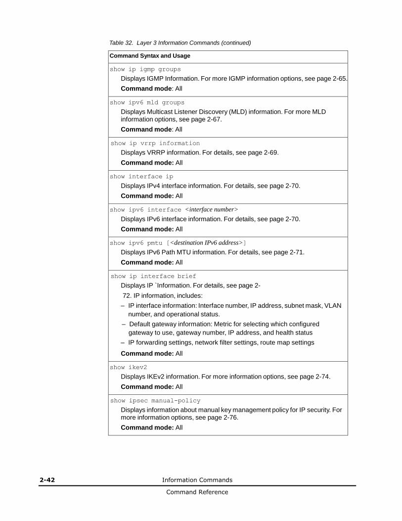
Table 32. Layer 3 Information Commands (continued)
Command Syntax and Usage
show ip igmp groups
Displays IGMP Information. For more IGMP information options, see page 2-65.
Command mode: All
show ipv6 mld groups
Displays Multicast Listener Discovery (MLD) information. For more MLD information options, see page 2-67.
Command mode: All
show ip vrrp information
Displays VRRP information. For details, see page 2-69.
Command mode: All
show interface ip
Displays IPv4 interface information. For details, see page 2-70.
Command mode: All
show ipv6 interface <interface number>
Displays IPv6 interface information. For details, see page 2-70.
Command mode: All
show ipv6 pmtu [<destination IPv6 address>]
Displays IPv6 Path MTU information. For details, see page 2-71.
Command mode: All
show ip interface brief
Displays IP `Information. For details, see page 2-
72. IP information, includes:
– IP interface information: Interface number, IP address, subnet mask, VLAN
number, and operational status.
– Default gateway information: Metric for selecting which configured
gateway to use, gateway number, IP address, and health status
– IP forwarding settings, network filter settings, route map settings
Command mode: All
show ikev2
Displays IKEv2 information. For more information options, see page 2-74.
Command mode: All
show ipsec manual-policy
Displays information about manual key management policy for IP security. For more information options, see page 2-76.
Command mode: All
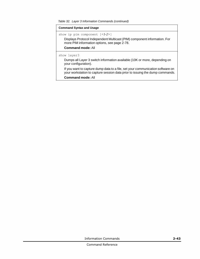
Information Commands 2-43
Command Reference
Table 32. Layer 3 Information Commands (continued)
Command Syntax and Usage
show ip pim component [<1-2>]
Displays Protocol Independent Multicast (PIM) component information. For more PIM information options, see page 2-78.
Command mode: All
show layer3
Dumps all Layer 3 switch information available (10K or more, depending on your configuration).
If you want to capture dump data to a file, set your communication software on your workstation to capture session data prior to issuing the dump commands.
Command mode: All
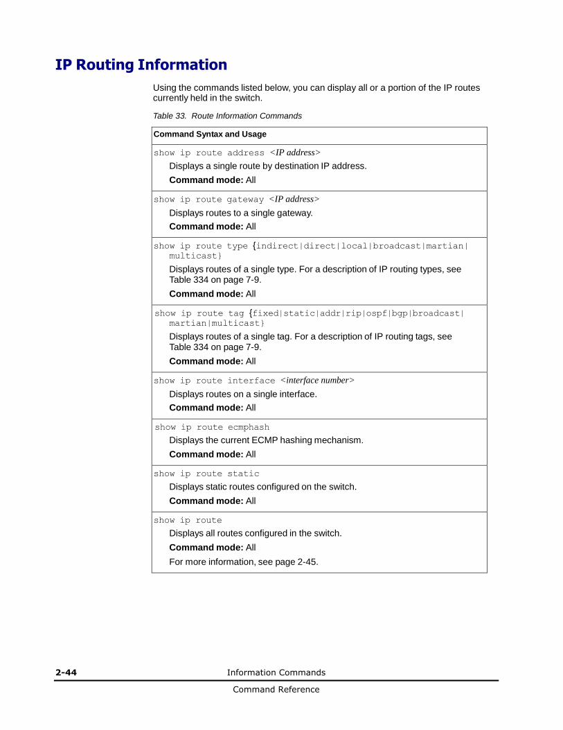
2-44 Information Commands
Command Reference
IP Routing Information
Using the commands listed below, you can display all or a portion of the IP routes currently held in the switch.
Table 33. Route Information Commands
Command Syntax and Usage
show ip route address <IP address>
Displays a single route by destination IP address.
Command mode: All
show ip route gateway <IP address>
Displays routes to a single gateway.
Command mode: All
show ip route type {indirect|direct|local|broadcast|martian| multicast}
Displays routes of a single type. For a description of IP routing types, see Table 334 on page 7-9.
Command mode: All
show ip route tag {fixed|static|addr|rip|ospf|bgp|broadcast| martian|multicast}
Displays routes of a single tag. For a description of IP routing tags, see Table 334 on page 7-9.
Command mode: All
show ip route interface <interface number>
Displays routes on a single interface.
Command mode: All
show ip route ecmphash
Displays the current ECMP hashing mechanism.
Command mode: All
show ip route static
Displays static routes configured on the switch.
Command mode: All
show ip route
Displays all routes configured in the switch.
Command mode: All
For more information, see page 2-45.
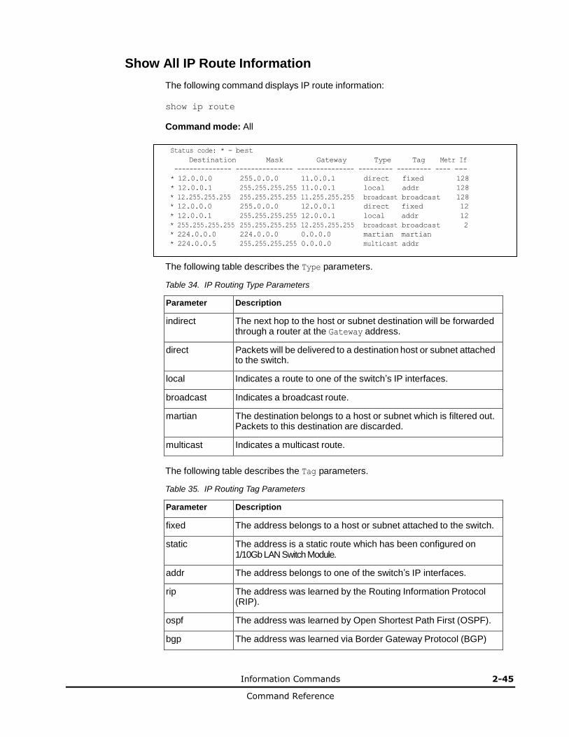
Information Commands 2-45
Command Reference
Show All IP Route Information
The following command displays IP route information:
show ip route
Command mode: All
Status code: * - best
Destination Mask Gateway Type Tag Metr If
--------------- --------------- --------------- --------- --------- ---- ---
* 12.0.0.0 255.0.0.0 11.0.0.1 direct fixed 128
* 12.0.0.1 255.255.255.255 11.0.0.1 local addr 128
* 12.255.255.255 255.255.255.255 11.255.255.255 broadcast broadcast 128
* 12.0.0.0 255.0.0.0 12.0.0.1 direct fixed 12
* 12.0.0.1 255.255.255.255 12.0.0.1 local addr 12
* 255.255.255.255 255.255.255.255 12.255.255.255 broadcast broadcast 2
* 224.0.0.0 224.0.0.0 0.0.0.0 martian martian * 224.0.0.5 255.255.255.255 0.0.0.0 multicast addr
The following table describes the Type parameters.
Table 34. IP Routing Type Parameters
Parameter Description
indirect The next hop to the host or subnet destination will be forwarded through a router at the Gateway address.
direct Packets will be delivered to a destination host or subnet attached to the switch.
local Indicates a route to one of the switch’s IP interfaces.
broadcast Indicates a broadcast route.
martian The destination belongs to a host or subnet which is filtered out. Packets to this destination are discarded.
multicast Indicates a multicast route.
The following table describes the Tag parameters.
Table 35. IP Routing Tag Parameters
Parameter Description
fixed The address belongs to a host or subnet attached to the switch.
static The address is a static route which has been configured on 1/10Gb LAN Switch Module.
addr The address belongs to one of the switch’s IP interfaces.
rip The address was learned by the Routing Information Protocol (RIP).
ospf The address was learned by Open Shortest Path First (OSPF).
bgp The address was learned via Border Gateway Protocol (BGP)
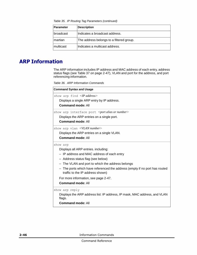
2-46 Information Commands
Command Reference
Table 35. IP Routing Tag Parameters (continued)
Parameter Description
broadcast Indicates a broadcast address.
martian The address belongs to a filtered group.
multicast Indicates a multicast address.
ARP Information
The ARP information includes IP address and MAC address of each entry, address status flags (see Table 37 on page 2-47), VLAN and port for the address, and port referencing information.
Table 36. ARP Information Commands
Command Syntax and Usage
show arp find <IP address>
Displays a single ARP entry by IP address.
Command mode: All
show arp interface port <port alias or number>
Displays the ARP entries on a single port.
Command mode: All
show arp vlan <VLAN number>
Displays the ARP entries on a single VLAN.
Command mode: All
show arp
Displays all ARP entries. including:
– IP address and MAC address of each entry
– Address status flag (see below)
– The VLAN and port to which the address belongs
– The ports which have referenced the address (empty if no port has routed
traffic to the IP address shown)
For more information, see page 2-47.
Command mode: All
show arp reply
Displays the ARP address list: IP address, IP mask, MAC address, and VLAN flags.
Command mode: All

Information Commands 2-47
Command Reference
Show All ARP Entry Information
The following command displays ARP information:
show arp
Command mode: All
IP address Flags MAC address VLAN Age Port
--------------- ----- ----------------- ---- --- -----
12.20.1.1 00:15:40:07:20:42 4095 0 INT8
12.20.20.16 00:30:13:e3:44:14 4095 2 INT8
12.20.20.18 00:30:13:e3:44:14 4095 2 INT6
12.20.23.111 00:1f:29:95:f7:e5 4095 6 INT6
The Port field shows the target port of the ARP entry.
The Flags field is interpreted as follows:
Table 37. ARP Dump Flag Parameters
Flag Description
P Permanent entry created for switch IP interface.
R Indirect route entry.
U Unresolved ARP entry. The MAC address has not been learned.
ARP Address List Information
The following command displays owned ARP address list information:
show arp reply
Command mode: All
IP address IP mask MAC address VLAN Pass-Up
--------------- --------------- ----------------- ---- -----
205.178.18.66 255.255.255.255 00:70:cf:03:20:04 P
205.178.50.1 255.255.255.255 00:70:cf:03:20:06 1 205.178.18.64 255.255.255.255 00:70:cf:03:20:05 1
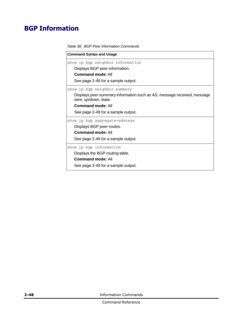
2-48 Information Commands
Command Reference
BGP Information
Table 38. BGP Peer Information Commands
Command Syntax and Usage
show ip bgp neighbor information
Displays BGP peer information.
Command mode: All
See page 2-49 for a sample output.
show ip bgp neighbor summary
Displays peer summary information such as AS, message received, message sent, up/down, state.
Command mode: All
See page 2-49 for a sample output.
show ip bgp aggregate-address
Displays BGP peer routes.
Command mode: All
See page 2-49 for a sample output.
show ip bgp information
Displays the BGP routing table.
Command mode: All
See page 2-49 for a sample output.
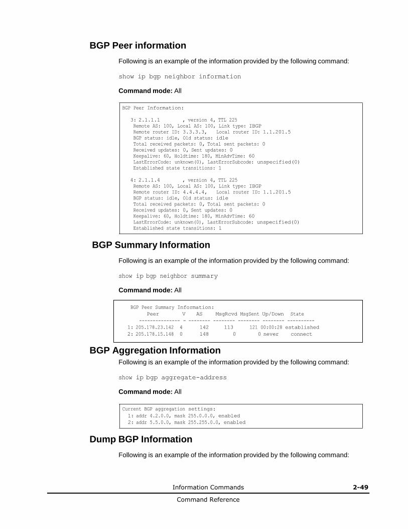
Information Commands 2-49
Command Reference
BGP Peer information
Following is an example of the information provided by the following command:
show ip bgp neighbor information
Command mode: All
BGP Peer Information:
3: 2.1.1.1 , version 4, TTL 225
Remote AS: 100, Local AS: 100, Link type: IBGP
Remote router ID: 3.3.3.3, Local router ID: 1.1.201.5
BGP status: idle, Old status: idle
Total received packets: 0, Total sent packets: 0
Received updates: 0, Sent updates: 0
Keepalive: 60, Holdtime: 180, MinAdvTime: 60
LastErrorCode: unknown(0), LastErrorSubcode: unspecified(0)
Established state transitions: 1
4: 2.1.1.4 , version 4, TTL 225
Remote AS: 100, Local AS: 100, Link type: IBGP
Remote router ID: 4.4.4.4, Local router ID: 1.1.201.5
BGP status: idle, Old status: idle
Total received packets: 0, Total sent packets: 0
Received updates: 0, Sent updates: 0
Keepalive: 60, Holdtime: 180, MinAdvTime: 60
LastErrorCode: unknown(0), LastErrorSubcode: unspecified(0)
Established state transitions: 1
BGP Summary Information
Following is an example of the information provided by the following command:
show ip bgp neighbor summary
Command mode: All
BGP Peer Summary Information:
Peer V AS MsgRcvd MsgSent Up/Down State
--------------- - -------- -------- -------- -------- ----------
1: 205.178.23.142 4 142 113 121 00:00:28 established
2: 205.178.15.148 0 148 0 0 never connect
BGP Aggregation Information Following is an example of the information provided by the following command:
show ip bgp aggregate-address
Command mode: All
Current BGP aggregation settings:
1: addr 4.2.0.0, mask 255.0.0.0, enabled
2: addr 5.5.0.0, mask 255.255.0.0, enabled
Dump BGP Information
Following is an example of the information provided by the following command:
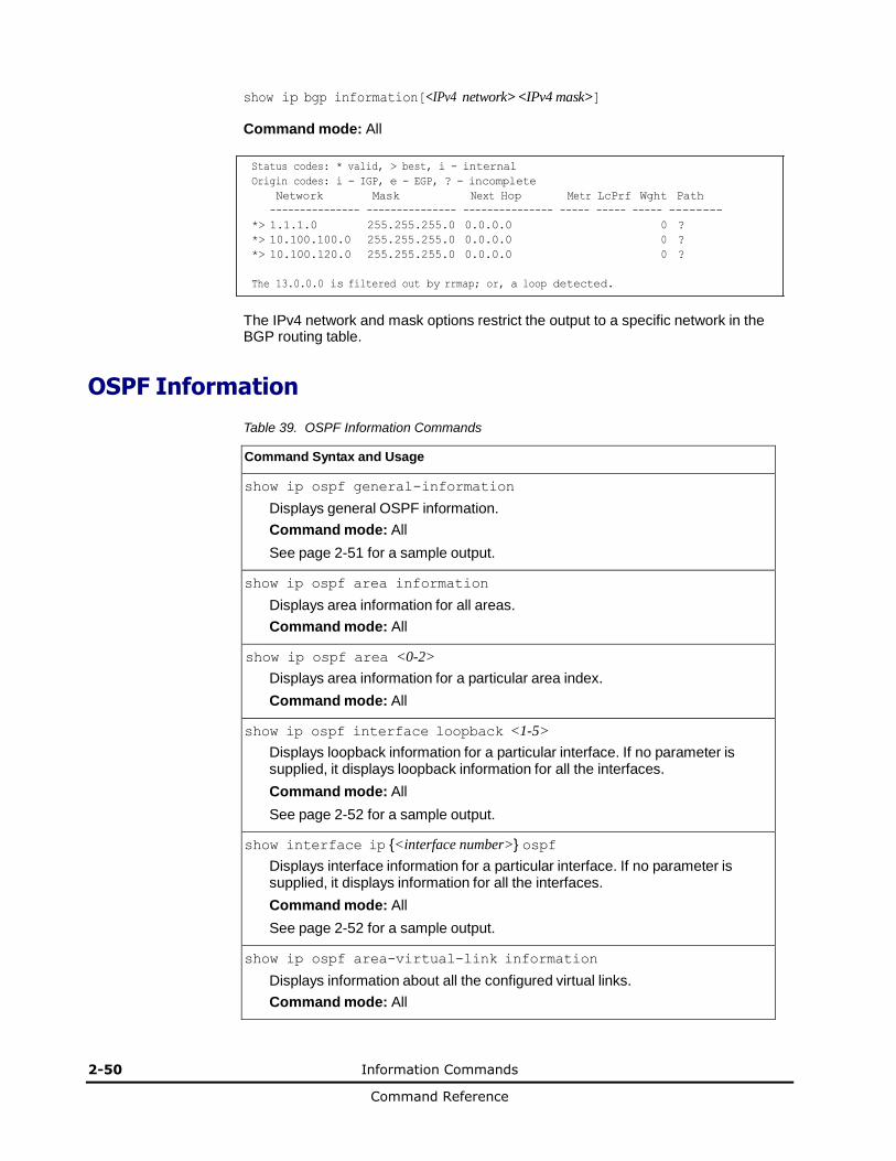
2-50 Information Commands
Command Reference
show ip bgp information[<IPv4 network> <IPv4 mask>]
Command mode: All
Status codes: * valid, > best, i - internal
Origin codes: i - IGP, e - EGP, ? - incomplete
Network Mask Next Hop Metr LcPrf Wght Path
--------------- --------------- --------------- ----- ----- ----- --------
*> 1.1.1.0 255.255.255.0 0.0.0.0 0 ?
*> 10.100.100.0 255.255.255.0 0.0.0.0 0 ?
*> 10.100.120.0 255.255.255.0 0.0.0.0 0 ?
The 13.0.0.0 is filtered out by rrmap; or, a loop detected.
The IPv4 network and mask options restrict the output to a specific network in the BGP routing table.
OSPF Information
Table 39. OSPF Information Commands
Command Syntax and Usage
show ip ospf general-information
Displays general OSPF information.
Command mode: All
See page 2-51 for a sample output.
show ip ospf area information
Displays area information for all areas.
Command mode: All
show ip ospf area <0-2>
Displays area information for a particular area index.
Command mode: All
show ip ospf interface loopback <1-5>
Displays loopback information for a particular interface. If no parameter is supplied, it displays loopback information for all the interfaces.
Command mode: All
See page 2-52 for a sample output.
show interface ip {<interface number>} ospf
Displays interface information for a particular interface. If no parameter is supplied, it displays information for all the interfaces.
Command mode: All
See page 2-52 for a sample output.
show ip ospf area-virtual-link information
Displays information about all the configured virtual links.
Command mode: All
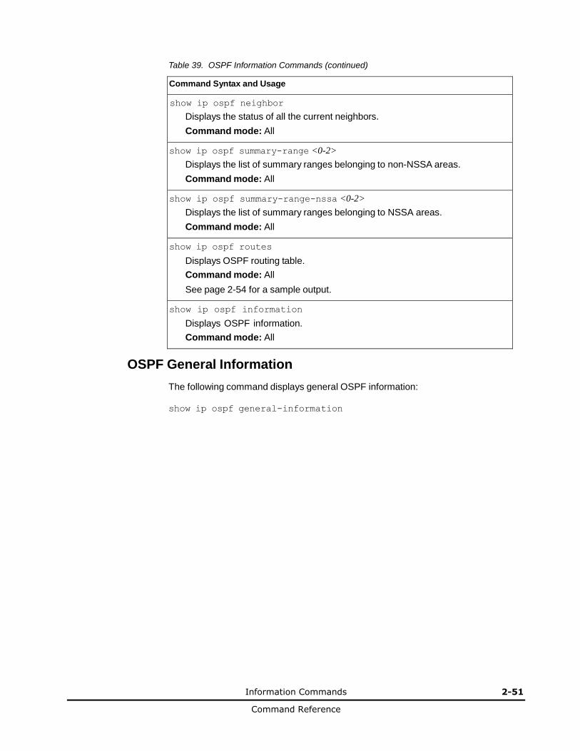
Information Commands 2-51
Command Reference
Table 39. OSPF Information Commands (continued)
Command Syntax and Usage
show ip ospf neighbor
Displays the status of all the current neighbors.
Command mode: All
show ip ospf summary-range <0-2>
Displays the list of summary ranges belonging to non-NSSA areas.
Command mode: All
show ip ospf summary-range-nssa <0-2>
Displays the list of summary ranges belonging to NSSA areas.
Command mode: All
show ip ospf routes
Displays OSPF routing table.
Command mode: All
See page 2-54 for a sample output.
show ip ospf information
Displays OSPF information.
Command mode: All
OSPF General Information
The following command displays general OSPF information:
show ip ospf general-information

2-52 Information Commands
Command Reference
Command mode: All
OSPF Version 2
Router ID: 10.10.10.1
Started at 1663 and the process uptime is 4626
Area Border Router: yes, AS Boundary Router: no
LS types supported are 6
External LSA count 0
External LSA checksum sum 0x0
Number of interfaces in this router is 2
Number of virtual links in this router is 1
16 new lsa received and 34 lsa originated from this router
Total number of entries in the LSDB 10
Database checksum sum 0x0
Total neighbors are 1, of which
2 are >=INIT state,
2 are >=EXCH state,
2 are =FULL state
Number of areas is 2, of which 3-transit 0-nssa
Area Id : 0.0.0.0
Authentication : none
Import ASExtern : yes
Number of times SPF ran : 8
Area Border Router count : 2
AS Boundary Router count : 0
LSA count : 5
LSA Checksum sum : 0x2237B
Summary : noSummary
OSPF Interface Loopback Information
The following command displays OSPF interface loopback information:
show ip ospf interface loopback <interface number>
Command mode: All
Ip Address 5.5.5.5, Area 0.0.0.1, Passive interface, Admin Status UP
Router ID 1.1.1.2, State Loopback, Priority 1
Designated Router (ID) 0.0.0.0, Ip Address 0.0.0.0
Backup Designated Router (ID) 0.0.0.0, Ip Address 0.0.0.0
Timer intervals, Hello 10, Dead 40, Wait 40, Retransmit 5, Transit delay
1
Neighbor count is 0 If Events 1, Authentication type none
OSPF Interface Information
The following command displays OSPF interface information:
show ip ospf interface <interface number>
Command mode: All
Ip Address 10.10.12.1, Area 0.0.0.1, Admin Status UP
Router ID 10.10.10.1, State DR, Priority 1
Designated Router (ID) 10.10.10.1, Ip Address 10.10.12.1
Backup Designated Router (ID) 10.10.14.1, Ip Address 10.10.12.2
Timer intervals, Hello 10, Dead 40, Wait 1663, Retransmit 5,
Neighbor count is 1 If Events 4, Authentication type none

Information Commands 2-53
Command Reference
OSPF Database Information
Table 40. OSPF Database Information Commands
Command Syntax and Usage
show ip ospf database advertising-router <router ID>
Takes advertising router as a parameter. Displays all the Link State Advertisements (LSAs) in the LS database that have the advertising router with the specified router ID, for example: 20.1.1.1.
Command mode: All
show ip ospf database asbr-summary
[advertising-router <router ID>|link-state-id <A.B.C.D>|self]
Displays ASBR summary LSAs. The use of this command is as follows:
a. asbr-summary advertising-router 20.1.1.1 displays ASBR summary LSAs having the advertising router 20.1.1.1.
b. asbr-summary link-state-id 10.1.1.1 displays ASBR summary LSAs
having the link state ID 10.1.1.1.
c. asbr-summary self displays the self advertised ASBR summary LSAs.
d. asbr-summary with no parameters displays all the ASBR summary LSAs.
Command mode: All
show ip ospf database database-summary
Displays the following information about the LS database in a table format:
a. Number of LSAs of each type in each area.
b. Total number of LSAs for each area.
c. Total number of LSAs for each LSA type for all areas combined.
d. Total number of LSAs for all LSA types for all areas combined.
No parameters are required.
Command mode: All
show ip ospf database external [advertising-router <router ID>| link-state-id <A.B.C.D>|self]
Displays the AS-external (type 5) LSAs with detailed information of each field of the LSAs.
Command mode: All
show ip ospf database network [advertising-router <router ID>| link-state-id <A.B.C.D>|self]
Displays the network (type 2) LSAs with detailed information of each field of the LSA.network LS database.
Command mode: All
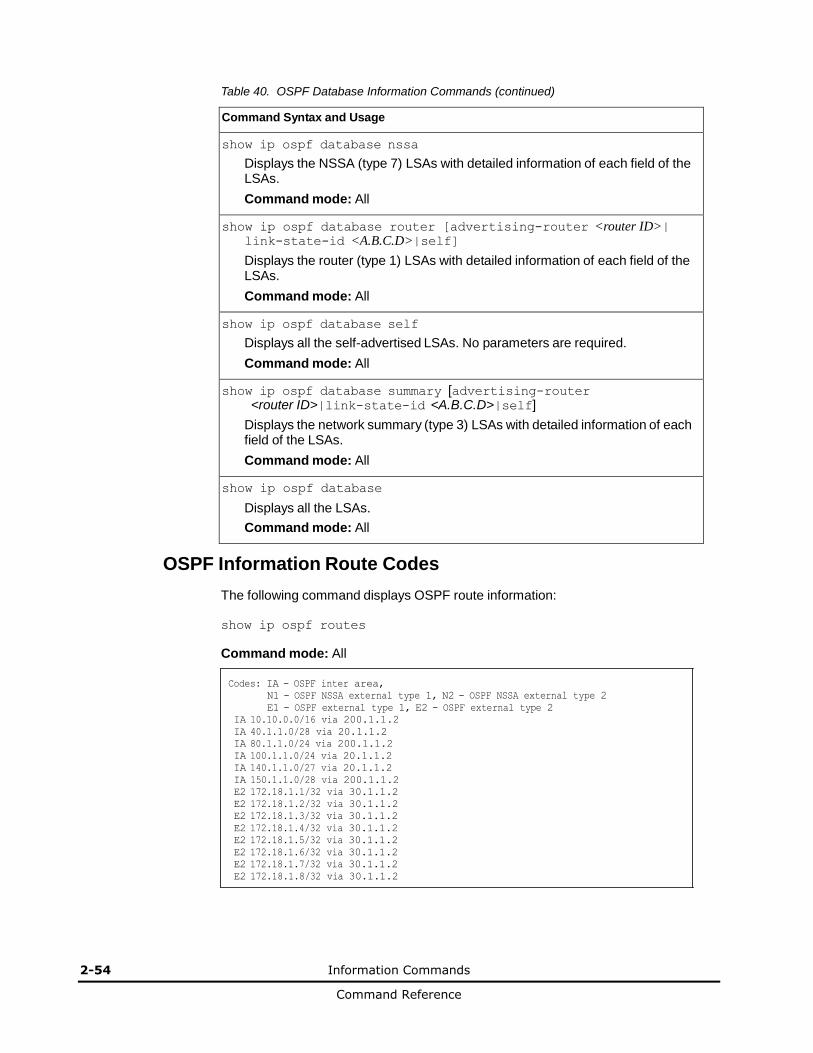
2-54 Information Commands
Command Reference
Table 40. OSPF Database Information Commands (continued)
Command Syntax and Usage
show ip ospf database nssa
Displays the NSSA (type 7) LSAs with detailed information of each field of the LSAs.
Command mode: All
show ip ospf database router [advertising-router <router ID>| link-state-id <A.B.C.D>|self]
Displays the router (type 1) LSAs with detailed information of each field of the LSAs.
Command mode: All
show ip ospf database self
Displays all the self-advertised LSAs. No parameters are required.
Command mode: All
show ip ospf database summary [advertising-router <router ID>|link-state-id <A.B.C.D>|self]
Displays the network summary (type 3) LSAs with detailed information of each field of the LSAs.
Command mode: All
show ip ospf database
Displays all the LSAs.
Command mode: All
OSPF Information Route Codes
The following command displays OSPF route information:
show ip ospf routes
Command mode: All
Codes: IA - OSPF inter area,
N1 - OSPF NSSA external type 1, N2 - OSPF NSSA external type 2
E1 - OSPF external type 1, E2 - OSPF external type 2
IA 10.10.0.0/16 via 200.1.1.2
IA 40.1.1.0/28 via 20.1.1.2
IA 80.1.1.0/24 via 200.1.1.2
IA 100.1.1.0/24 via 20.1.1.2
IA 140.1.1.0/27 via 20.1.1.2
IA 150.1.1.0/28 via 200.1.1.2
E2 172.18.1.1/32 via 30.1.1.2
E2 172.18.1.2/32 via 30.1.1.2
E2 172.18.1.3/32 via 30.1.1.2
E2 172.18.1.4/32 via 30.1.1.2
E2 172.18.1.5/32 via 30.1.1.2
E2 172.18.1.6/32 via 30.1.1.2
E2 172.18.1.7/32 via 30.1.1.2
E2 172.18.1.8/32 via 30.1.1.2
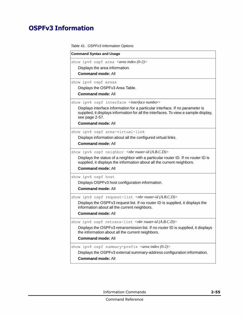
Information Commands 2-55
Command Reference
OSPFv3 Information
Table 41. OSPFv3 Information Options
Command Syntax and Usage
show ipv6 ospf area <area index (0-2)>
Displays the area information.
Command mode: All
show ipv6 ospf areas
Displays the OSPFv3 Area Table.
Command mode: All
show ipv6 ospf interface <interface number>
Displays interface information for a particular interface. If no parameter is supplied, it displays information for all the interfaces. To view a sample display, see page 2-57.
Command mode: All
show ipv6 ospf area-virtual-link
Displays information about all the configured virtual links.
Command mode: All
show ipv6 ospf neighbor <nbr router-id (A.B.C.D)>
Displays the status of a neighbor with a particular router ID. If no router ID is supplied, it displays the information about all the current neighbors.
Command mode: All
show ipv6 ospf host
Displays OSPFv3 host configuration information.
Command mode: All
show ipv6 ospf request-list <nbr router-id (A.B.C.D)>
Displays the OSPFv3 request list. If no router ID is supplied, it displays the information about all the current neighbors.
Command mode: All
show ipv6 ospf retrans-list <nbr router-id (A.B.C.D)>
Displays the OSPFv3 retransmission list. If no router ID is supplied, it displays the information about all the current neighbors.
Command mode: All
show ipv6 ospf summary-prefix <area index (0-2)>
Displays the OSPFv3 external summary-address configuration information.
Command mode: All
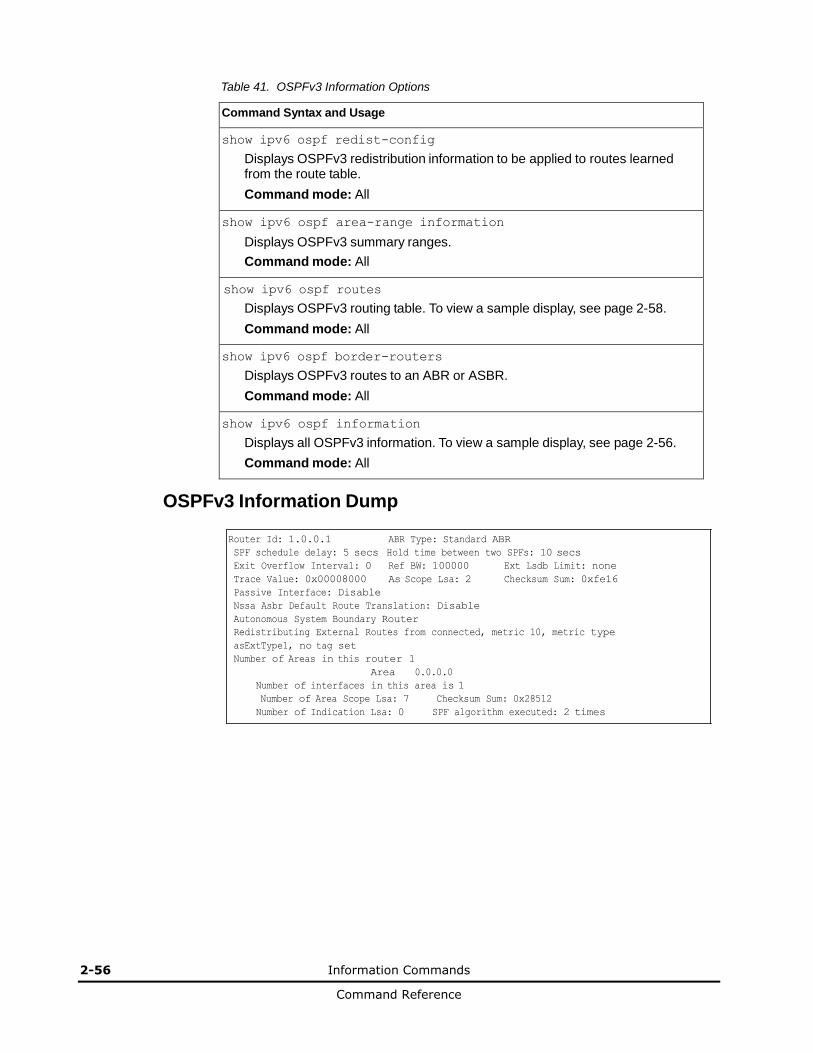
2-56 Information Commands
Command Reference
Table 41. OSPFv3 Information Options
Command Syntax and Usage
show ipv6 ospf redist-config
Displays OSPFv3 redistribution information to be applied to routes learned from the route table.
Command mode: All
show ipv6 ospf area-range information
Displays OSPFv3 summary ranges.
Command mode: All
show ipv6 ospf routes
Displays OSPFv3 routing table. To view a sample display, see page 2-58.
Command mode: All
show ipv6 ospf border-routers
Displays OSPFv3 routes to an ABR or ASBR.
Command mode: All
show ipv6 ospf information
Displays all OSPFv3 information. To view a sample display, see page 2-56.
Command mode: All
OSPFv3 Information Dump
Router Id: 1.0.0.1 ABR Type: Standard ABR
SPF schedule delay: 5 secs Hold time between two SPFs: 10 secs
Exit Overflow Interval: 0 Ref BW: 100000 Ext Lsdb Limit: none
Trace Value: 0x00008000 As Scope Lsa: 2 Checksum Sum: 0xfe16
Passive Interface: Disable
Nssa Asbr Default Route Translation: Disable
Autonomous System Boundary Router
Redistributing External Routes from connected, metric 10, metric type
asExtType1, no tag set
Number of Areas in this router 1
Area 0.0.0.0
Number of interfaces in this area is 1
Number of Area Scope Lsa: 7 Checksum Sum: 0x28512
Number of Indication Lsa: 0 SPF algorithm executed: 2 times
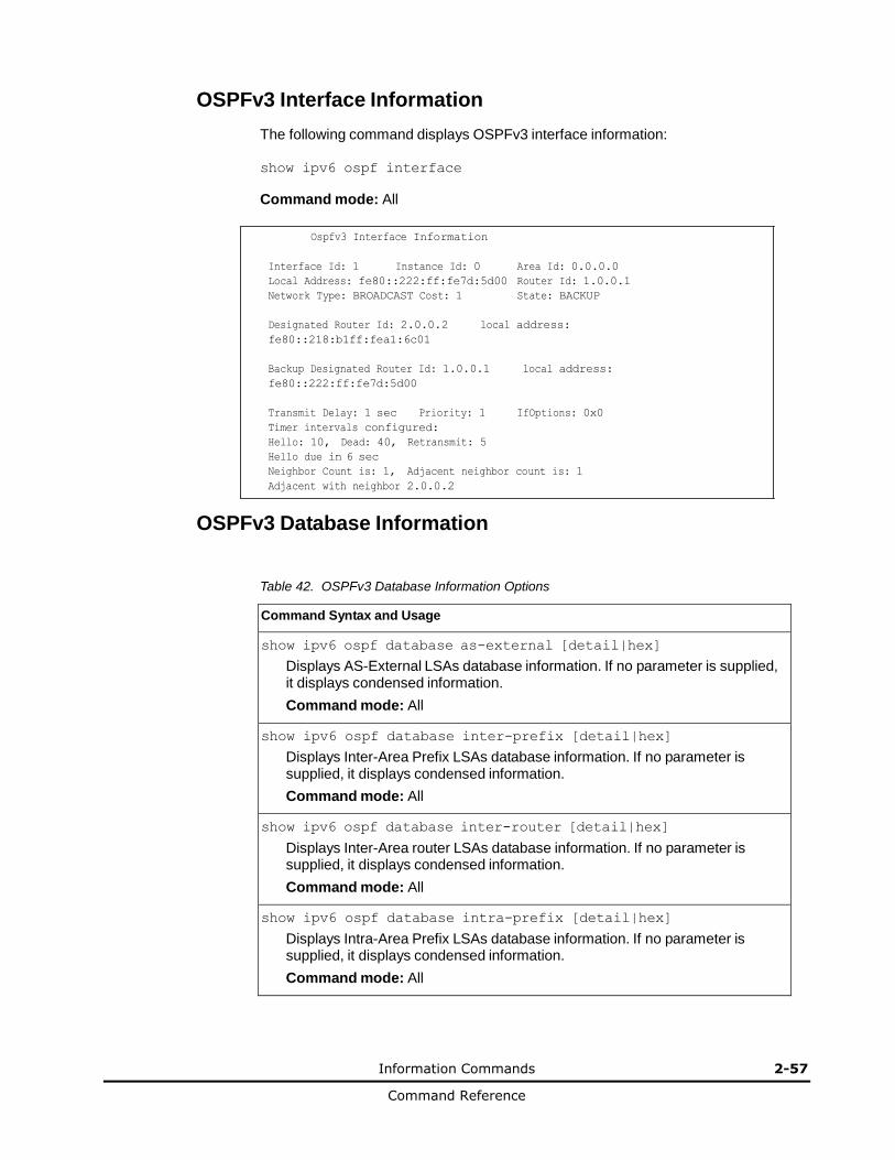
Information Commands 2-57
Command Reference
OSPFv3 Interface Information
The following command displays OSPFv3 interface information:
show ipv6 ospf interface
Command mode: All
Ospfv3 Interface Information
Interface Id: 1 Instance Id: 0 Area Id: 0.0.0.0
Local Address: fe80::222:ff:fe7d:5d00 Router Id: 1.0.0.1
Network Type: BROADCAST Cost: 1 State: BACKUP
Designated Router Id: 2.0.0.2 local address:
fe80::218:b1ff:fea1:6c01
Backup Designated Router Id: 1.0.0.1 local address:
fe80::222:ff:fe7d:5d00
Transmit Delay: 1 sec Priority: 1 IfOptions: 0x0
Timer intervals configured:
Hello: 10, Dead: 40, Retransmit: 5
Hello due in 6 sec
Neighbor Count is: 1, Adjacent neighbor count is: 1
Adjacent with neighbor 2.0.0.2
OSPFv3 Database Information
Table 42. OSPFv3 Database Information Options
Command Syntax and Usage
show ipv6 ospf database as-external [detail|hex]
Displays AS-External LSAs database information. If no parameter is supplied, it displays condensed information.
Command mode: All
show ipv6 ospf database inter-prefix [detail|hex]
Displays Inter-Area Prefix LSAs database information. If no parameter is supplied, it displays condensed information.
Command mode: All
show ipv6 ospf database inter-router [detail|hex]
Displays Inter-Area router LSAs database information. If no parameter is supplied, it displays condensed information.
Command mode: All
show ipv6 ospf database intra-prefix [detail|hex]
Displays Intra-Area Prefix LSAs database information. If no parameter is supplied, it displays condensed information.
Command mode: All
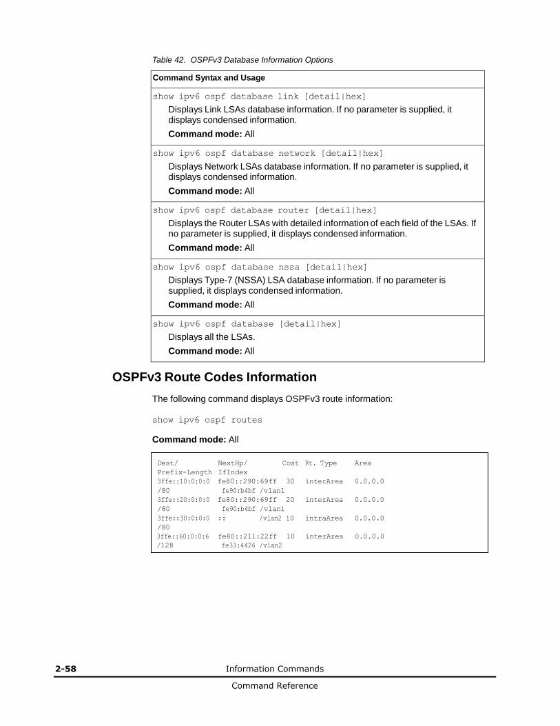
2-58 Information Commands
Command Reference
Table 42. OSPFv3 Database Information Options
Command Syntax and Usage
show ipv6 ospf database link [detail|hex]
Displays Link LSAs database information. If no parameter is supplied, it displays condensed information.
Command mode: All
show ipv6 ospf database network [detail|hex]
Displays Network LSAs database information. If no parameter is supplied, it displays condensed information.
Command mode: All
show ipv6 ospf database router [detail|hex]
Displays the Router LSAs with detailed information of each field of the LSAs. If no parameter is supplied, it displays condensed information.
Command mode: All
show ipv6 ospf database nssa [detail|hex]
Displays Type-7 (NSSA) LSA database information. If no parameter is supplied, it displays condensed information.
Command mode: All
show ipv6 ospf database [detail|hex]
Displays all the LSAs.
Command mode: All
OSPFv3 Route Codes Information
The following command displays OSPFv3 route information:
show ipv6 ospf routes
Command mode: All
Dest/ NextHp/ Cost Rt. Type Area
Prefix-Length IfIndex
3ffe::10:0:0:0 fe80::290:69ff 30 interArea 0.0.0.0
/80 fe90:b4bf /vlan1
3ffe::20:0:0:0 fe80::290:69ff 20 interArea 0.0.0.0
/80 fe90:b4bf /vlan1
3ffe::30:0:0:0 :: /vlan2 10 intraArea 0.0.0.0
/80
3ffe::60:0:0:6 fe80::211:22ff 10 interArea 0.0.0.0
/128 fe33:4426 /vlan2

Information Commands 2-59
Command Reference
Routing Information Protocol
Table 43. Routing Information Protocol Commands
Command Syntax and Usage
show ip rip routes
Displays RIP routes.
Command mode: All
For more information, see page 2-59.
show interface ip <interface number> rip
Displays RIP user’s configuration. Command
mode: All
For more information, see page 2-59.
RIP Routes Information
The following command displays RIP route information:
show ip rip routes
Command mode: All
>> IP Routing#
30.1.1.0/24 directly connected
3.0.0.0/8 via 30.1.1.11 metric 4
4.0.0.0/16 via 30.1.1.11 metric 16
10.0.0.0/8 via 30.1.1.2 metric 3
20.0.0.0/8 via 30.1.1.2 metric 2
This table contains all dynamic routes learned through RIP, including the routes that are undergoing garbage collection with metric = 16. This table does not contain locally configured static routes.
RIP Interface Information
The following command displays RIP user information:
show ip rip interface <interface number>
Command mode: All
RIP USER CONFIGURATION :
RIP: ON, update 30
RIP on Interface 49 : 101.1.1.10, enabled
version 2, listen enabled, supply enabled, default none
poison disabled, split horizon enabled, trigg enabled, mcast enabled, metric 1
auth none,key none
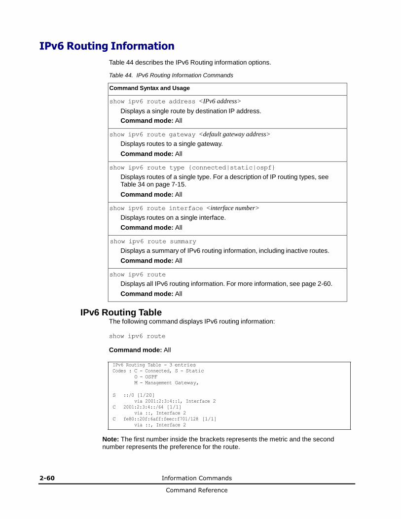
2-60 Information Commands
Command Reference
IPv6 Routing Information
Table 44 describes the IPv6 Routing information options.
Table 44. IPv6 Routing Information Commands
Command Syntax and Usage
show ipv6 route address <IPv6 address>
Displays a single route by destination IP address.
Command mode: All
show ipv6 route gateway <default gateway address>
Displays routes to a single gateway.
Command mode: All
show ipv6 route type {connected|static|ospf}
Displays routes of a single type. For a description of IP routing types, see Table 34 on page 7-15.
Command mode: All
show ipv6 route interface <interface number>
Displays routes on a single interface.
Command mode: All
show ipv6 route summary
Displays a summary of IPv6 routing information, including inactive routes.
Command mode: All
show ipv6 route
Displays all IPv6 routing information. For more information, see page 2-60.
Command mode: All
IPv6 Routing Table The following command displays IPv6 routing information:
show ipv6 route
Command mode: All
IPv6 Routing Table - 3 entries
Codes : C - Connected, S - Static
O - OSPF
M - Management Gateway,
S ::/0 [1/20]
via 2001:2:3:4::1, Interface 2
C 2001:2:3:4::/64 [1/1]
via ::, Interface 2
C fe80::20f:6aff:feec:f701/128 [1/1]
via ::, Interface 2
Note: The first number inside the brackets represents the metric and the second number represents the preference for the route.
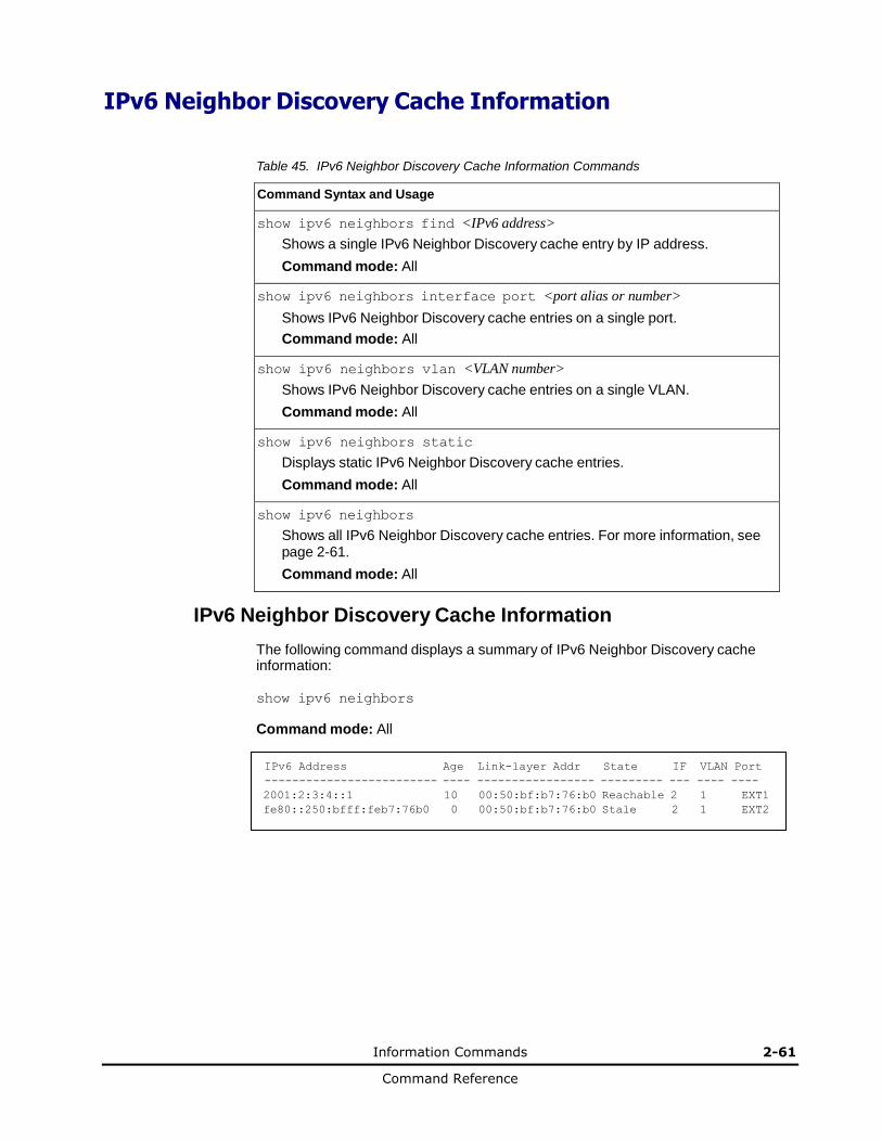
Information Commands 2-61
Command Reference
IPv6 Neighbor Discovery Cache Information
Table 45. IPv6 Neighbor Discovery Cache Information Commands
Command Syntax and Usage
show ipv6 neighbors find <IPv6 address>
Shows a single IPv6 Neighbor Discovery cache entry by IP address.
Command mode: All
show ipv6 neighbors interface port <port alias or number>
Shows IPv6 Neighbor Discovery cache entries on a single port.
Command mode: All
show ipv6 neighbors vlan <VLAN number>
Shows IPv6 Neighbor Discovery cache entries on a single VLAN.
Command mode: All
show ipv6 neighbors static
Displays static IPv6 Neighbor Discovery cache entries.
Command mode: All
show ipv6 neighbors
Shows all IPv6 Neighbor Discovery cache entries. For more information, see page 2-61.
Command mode: All
IPv6 Neighbor Discovery Cache Information
The following command displays a summary of IPv6 Neighbor Discovery cache information:
show ipv6 neighbors
Command mode: All
IPv6 Address Age Link-layer Addr State IF VLAN Port
------------------------- ---- ----------------- --------- --- ---- ----
2001:2:3:4::1 10 00:50:bf:b7:76:b0 Reachable 2 1 EXT1
fe80::250:bfff:feb7:76b0 0 00:50:bf:b7:76:b0 Stale 2 1 EXT2

2-62 Information Commands
Command Reference
IPv6 Neighbor Discovery Prefix Information
The following command displays a summary of IPv6 Neighbor Discovery prefix information:
show ipv6 prefix
Command mode: All
Codes: A - Address , P - Prefix-Advertisement
D - Default , N - Not Advertised
[L] - On-link Flag is set
[A] - Autonomous Flag is set
AD 10:: 64 [LA] Valid lifetime 2592000 , Preferred lifetime 604800
P 20:: 64 [LA] Valid lifetime 200 , Preferred lifetime 100
Neighbor Discovery prefix information includes information about all configured prefixes.
The following command displays IPv6 Neighbor Discovery prefix information for an interface:
show ipv6 prefix interface <interface number>
Command mode: All
ECMP Static Route Information
The following command displays Equal Cost Multi-Path (ECMP) route information:
show ip ecmp
Command mode: All
Current ecmp static routes:
Destination
-------------
10.10.1.1
Mask Gateway
-- --------------- -------------
255.255.255.255 100.10.1.1
If
-- --
--
1
GW Status
-----------
up
200.20.2.2 1 down
10.20.2.2
255.255.255.255 10.233.3.3
1
up
10.20.2.2 255.255.255.255 10.234.4.4 1 up
10.20.2.2 255.255.255.255 10.235.5.5 1 up
ECMP route information shows the status of each ECMP route configured on the switch.
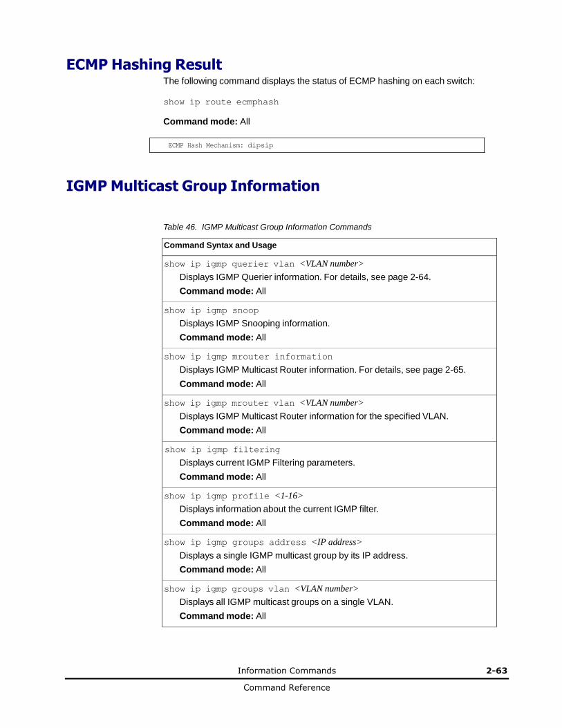
Information Commands 2-63
Command Reference
ECMP Hashing Result The following command displays the status of ECMP hashing on each switch:
show ip route ecmphash
Command mode: All
ECMP Hash Mechanism: dipsip
IGMP Multicast Group Information
Table 46. IGMP Multicast Group Information Commands
Command Syntax and Usage
show ip igmp querier vlan <VLAN number>
Displays IGMP Querier information. For details, see page 2-64.
Command mode: All
show ip igmp snoop
Displays IGMP Snooping information.
Command mode: All
show ip igmp mrouter information
Displays IGMP Multicast Router information. For details, see page 2-65.
Command mode: All
show ip igmp mrouter vlan <VLAN number>
Displays IGMP Multicast Router information for the specified VLAN.
Command mode: All
show ip igmp filtering
Displays current IGMP Filtering parameters.
Command mode: All
show ip igmp profile <1-16>
Displays information about the current IGMP filter.
Command mode: All
show ip igmp groups address <IP address>
Displays a single IGMP multicast group by its IP address.
Command mode: All
show ip igmp groups vlan <VLAN number>
Displays all IGMP multicast groups on a single VLAN.
Command mode: All
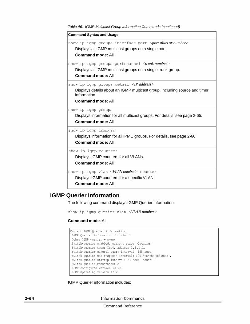
2-64 Information Commands
Command Reference
Table 46. IGMP Multicast Group Information Commands (continued)
Command Syntax and Usage
show ip igmp groups interface port <port alias or number>
Displays all IGMP multicast groups on a single port.
Command mode: All
show ip igmp groups portchannel <trunk number>
Displays all IGMP multicast groups on a single trunk group.
Command mode: All
show ip igmp groups detail <IP address>
Displays details about an IGMP multicast group, including source and timer information.
Command mode: All
show ip igmp groups
Displays information for all multicast groups. For details, see page 2-65.
Command mode: All
show ip igmp ipmcgrp
Displays information for all IPMC groups. For details, see page 2-66.
Command mode: All
show ip igmp counters
Displays IGMP counters for all VLANs.
Command mode: All
show ip igmp vlan <VLAN number> counter
Displays IGMP counters for a specific VLAN.
Command mode: All
IGMP Querier Information The following command displays IGMP Querier information:
show ip igmp querier vlan <VLAN number>
Command mode: All
Current IGMP Querier information:
IGMP Querier information for vlan 1:
Other IGMP querier - none
Switch-querier enabled, current state: Querier
Switch-querier type: Ipv4, address 1.1.1.1,
Switch-querier general query interval: 125 secs,
Switch-querier max-response interval: 100 'tenths of secs',
Switch-querier startup interval: 31 secs, count: 2
Switch-querier robustness: 2
IGMP configured version is v3
IGMP Operating version is v3
IGMP Querier information includes:
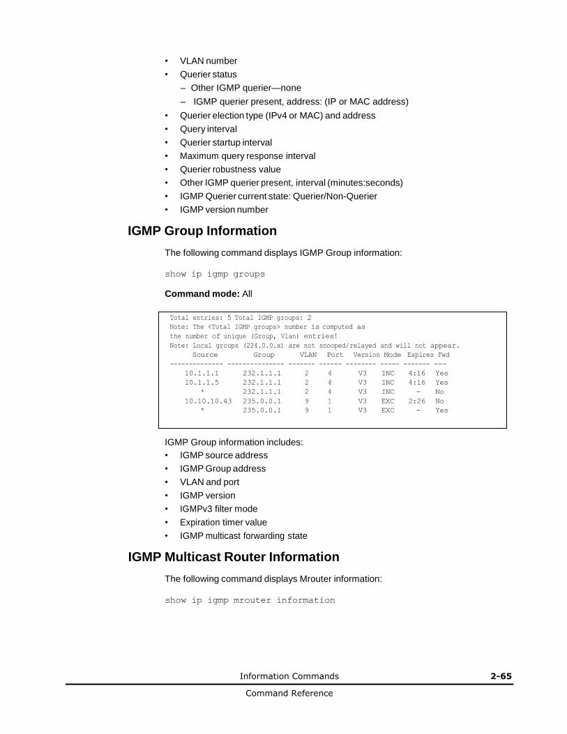
Information Commands 2-65
Command Reference
• VLAN number
• Querier status
– Other IGMP querier—none
– IGMP querier present, address: (IP or MAC address)
• Querier election type (IPv4 or MAC) and address
• Query interval
• Querier startup interval
• Maximum query response interval
• Querier robustness value
• Other IGMP querier present, interval (minutes:seconds)
• IGMP Querier current state: Querier/Non-Querier
• IGMP version number
IGMP Group Information
The following command displays IGMP Group information:
show ip igmp groups
Command mode: All
Total entries: 5 Total IGMP groups: 2
Note: The <Total IGMP groups> number is computed as
the number of unique (Group, Vlan) entries!
Note: Local groups (224.0.0.x) are not snooped/relayed and will not appear.
Source Group VLAN Port Version Mode Expires Fwd
-------------- --------------- ------- ------ -------- ----- ------- ---
10.1.1.1 232.1.1.1 2 4 V3 INC 4:16 Yes
10.1.1.5 232.1.1.1 2 4 V3 INC 4:16 Yes
* 232.1.1.1 2 4 V3 INC - No
10.10.10.43 235.0.0.1 9 1 V3 EXC 2:26 No
* 235.0.0.1 9 1 V3 EXC - Yes
IGMP Group information includes:
• IGMP source address
• IGMP Group address
• VLAN and port
• IGMP version
• IGMPv3 filter mode
• Expiration timer value
• IGMP multicast forwarding state
IGMP Multicast Router Information
The following command displays Mrouter information:
show ip igmp mrouter information
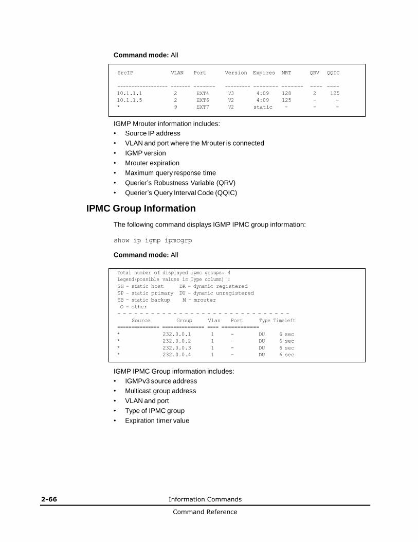
2-66 Information Commands
Command Reference
Command mode: All
SrcIP VLAN Port Version Expires MRT QRV QQIC
------------------ ------- ------- --------- -------- ------- ---- ----
10.1.1.1 2 EXT4 V3 4:09 128 2 125
10.1.1.5 2 EXT6 V2 4:09 125 - -
* 9 EXT7 V2 static - - -
IGMP Mrouter information includes:
• Source IP address
• VLAN and port where the Mrouter is connected
• IGMP version
• Mrouter expiration
• Maximum query response time
• Querier’s Robustness Variable (QRV)
• Querier’s Query Interval Code (QQIC)
IPMC Group Information
The following command displays IGMP IPMC group information:
show ip igmp ipmcgrp
Command mode: All
Total number of displayed ipmc groups: 4
Legend(possible values in Type column) :
SH - static host DR - dynamic registered
SP - static primary DU - dynamic unregistered
SB - static backup M - mrouter
O - other
- - - - - - - - - - - - - - - - - - - - - - - - - - - - - - -
Source Group Vlan Port Type Timeleft
=============== =============== ==== ============
* 232.0.0.1 1 - DU 6 sec
* 232.0.0.2 1 - DU 6 sec
* 232.0.0.3 1 - DU 6 sec
* 232.0.0.4 1 - DU 6 sec
IGMP IPMC Group information includes:
• IGMPv3 source address
• Multicast group address
• VLAN and port
• Type of IPMC group
• Expiration timer value

Information Commands 2-67
Command Reference
MLD information
Table 47 describes the commands used to view Multicast Listener Discovery (MLD) information.
Table 47. MLD Information Commands
Command Syntax and Usage
show ipv6 mld groups
Displays MLD multicast group information.
Command mode: All
show ipv6 mld groups address <IPv6 address>
Displays group information for the specified IPv6 address.
Command mode: All
show ipv6 mld groups interface port <port alias or number>
Displays MLD groups on a single interface port.
Command mode: All
show ipv6 mld groups portchannel <trunk group number>
Displays groups on a single port channel.
Command mode: All
show ipv6 mld groups vlan <VLAN number>
Displays groups on a single VLAN.
Command mode: All
show ipv6 mld mrouter
Displays all MLD Mrouter ports. See page 2-68 for sample output.
Command mode: All

2-68 Information Commands
Command Reference
MLD Mrouter Information
The following command displays MLD Mrouter information:
show ipv6 mld mrouter
Command mode: All
Source: fe80:0:0:0:200:14ff:fea8:40c9
Port/Vlan: 26/4
Interface: 3
QRV: 2 QQIC:125
Maximum Response Delay: 1000
Version: MLDv2 Expires:1:02
The following table describes the MLD Mrouter information displayed in the output.
Table 48. MLD Mrouter
Statistic Description
Source Displays the link-local address of the reporter.
Port/Vlan Displays the port/vlan on which the general query is received.
Interface Displays the interface number on which the general query is received.
QRV Displays the Querier’s robustness variable value.
QQIC Displays the Querier’s query interval code.
Maximum Response Delay
Displays the configured maximum query response time.
Version Displays the MLD version configured on the interface.
Expires Displays the amount of time that must pass before the multicast router decides that there are no more listeners for a multicast address or a particular source on a link.
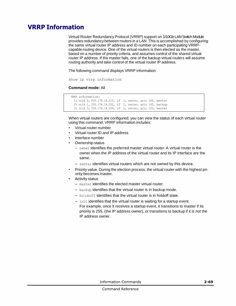
Information Commands 2-69
Command Reference
VRRP Information
Virtual Router Redundancy Protocol (VRRP) support on 1/10Gb LAN Switch Module
provides redundancy between routers in a LAN. This is accomplished by configuring the same virtual router IP address and ID number on each participating VRRP-capable routing device. One of the virtual routers is then elected as the master, based on a number of priority criteria, and assumes control of the shared virtual router IP address. If the master fails, one of the backup virtual routers will assume routing authority and take control of the virtual router IP address.
The following command displays VRRP information:
show ip vrrp information
Command mode: All VRRP information:
1: vrid 2, 205.178.18.210, if 1, renter, prio 100, master
2: vrid 1, 205.178.18.202, if 1, renter, prio 100, backup
3: vrid 3, 205.178.18.204, if 1, renter, prio 100, master
When virtual routers are configured, you can view the status of each virtual router using this command. VRRP information includes:
• Virtual router number
• Virtual router ID and IP address
• Interface number
• Ownership status
– owner identifies the preferred master virtual router. A virtual router is the
owner when the IP address of the virtual router and its IP interface are the
same.
– renter identifies virtual routers which are not owned by this device.
• Priority value. During the election process, the virtual router with the highest pri- ority becomes master.
• Activity status
– master identifies the elected master virtual router.
– backup identifies that the virtual router is in backup mode.
– holdoff identifies that the virtual router is in holdoff state.
– init identifies that the virtual router is waiting for a startup event.
For example, once it receives a startup event, it transitions to master if its
priority is 255, (the IP address owner), or transitions to backup if it is not the
IP address owner.
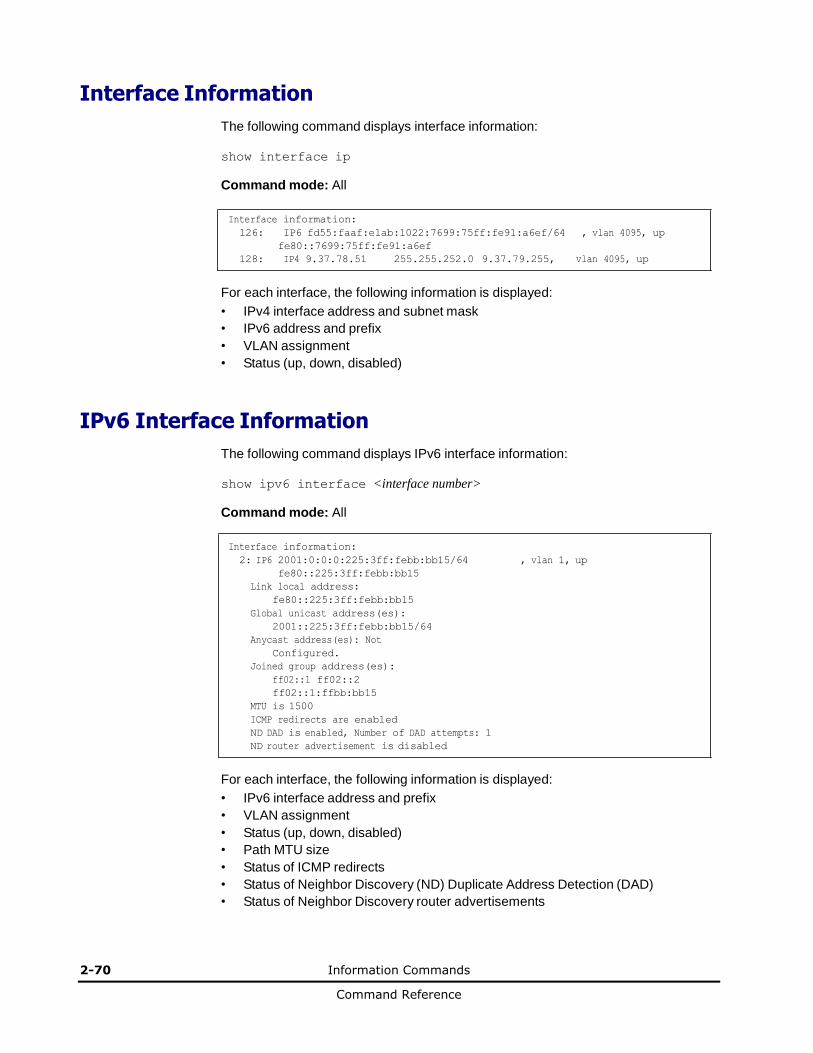
2-70 Information Commands
Command Reference
Interface Information
The following command displays interface information:
show interface ip
Command mode: All
Interface information:
126: IP6 fd55:faaf:e1ab:1022:7699:75ff:fe91:a6ef/64 , vlan 4095, up
fe80::7699:75ff:fe91:a6ef
128: IP4 9.37.78.51 255.255.252.0 9.37.79.255, vlan 4095, up
For each interface, the following information is displayed:
• IPv4 interface address and subnet mask
• IPv6 address and prefix
• VLAN assignment
• Status (up, down, disabled)
IPv6 Interface Information
The following command displays IPv6 interface information:
show ipv6 interface <interface number>
Command mode: All
Interface information:
2: IP6 2001:0:0:0:225:3ff:febb:bb15/64 , vlan 1, up
fe80::225:3ff:febb:bb15
Link local address:
fe80::225:3ff:febb:bb15
Global unicast address(es):
2001::225:3ff:febb:bb15/64
Anycast address(es): Not
Configured.
Joined group address(es):
ff02::1 ff02::2
ff02::1:ffbb:bb15
MTU is 1500
ICMP redirects are enabled
ND DAD is enabled, Number of DAD attempts: 1
ND router advertisement is disabled
For each interface, the following information is displayed:
• IPv6 interface address and prefix
• VLAN assignment
• Status (up, down, disabled)
• Path MTU size
• Status of ICMP redirects
• Status of Neighbor Discovery (ND) Duplicate Address Detection (DAD)
• Status of Neighbor Discovery router advertisements
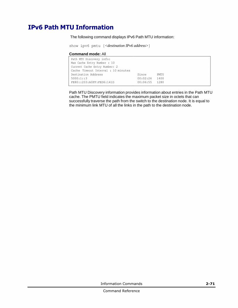
Information Commands 2-71
Command Reference
IPv6 Path MTU Information
The following command displays IPv6 Path MTU information:
show ipv6 pmtu [<destination IPv6 address>]
Command mode: All
Path MTU Discovery info: Max Cache Entry Number : 10
Current Cache Entry Number: 2
Cache Timeout Interval : 10 minutes
Destination Address Since PMTU
5000:1::3 00:02:26 1400
FE80::203:A0FF:FED6:141D 00:06:55 1280
Path MTU Discovery information provides information about entries in the Path MTU cache. The PMTU field indicates the maximum packet size in octets that can successfully traverse the path from the switch to the destination node. It is equal to the minimum link MTU of all the links in the path to the destination node.

2-72 Information Commands
Command Reference
IP Information
The following command displays Layer 3 information:
show ip interface brief
Command mode: All
IP information:
AS number 0
Interface information:
126: IP6 0:0:0:0:0:0:0:0/0 , vlan 4095, up
fe80::200:ff:fe00:ef
128: IP4 9.43.95.121 255.255.255.0 9.43.95.255, vlan 4095, up
Loopback interface information:
Default gateway information: metric strict
4: 9.43.95.254, FAILED
Default IP6 gateway information:
Current BOOTP relay settings: OFF
Global servers:
-------------------------
Server 1 address 0.0.0.0
Server 2 address 0.0.0.0
Server 3 address 0.0.0.0
Server 4 address 0.0.0.0
Server 5 address 0.0.0.0
Current IP forwarding settings: ON, dirbr disabled, icmprd disabled
Current network filter settings:
none
Current route map settings:
RIP is disabled.
OSPF is disabled.
OSPFv3 is disabled.
BGP is disabled.
IP information includes:
• IP interface information: Interface number, IP address, subnet mask, broadcast address, VLAN number, and operational status.
• Default gateway information: Metric for selecting which configured gateway to use, gateway number, IP address, and health status
• BootP relay settings
• IP forwarding settings, including the forwarding status of directed broadcasts, and the status of ICMP re-directs
• Network filter settings, if applicable
• Route map settings, if applicable
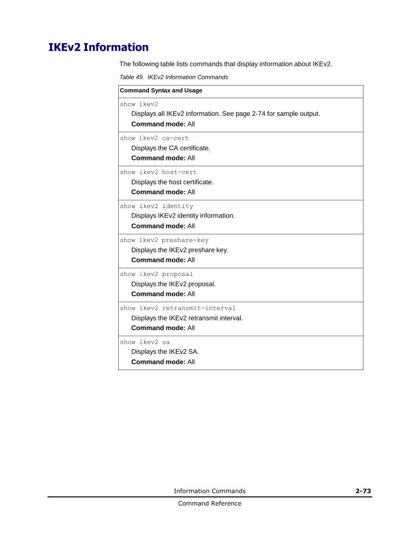
Information Commands 2-73
Command Reference
IKEv2 Information
The following table lists commands that display information about IKEv2.
Table 49. IKEv2 Information Commands
Command Syntax and Usage
show ikev2
Displays all IKEv2 information. See page 2-74 for sample output.
Command mode: All
show ikev2 ca-cert
Displays the CA certificate.
Command mode: All
show ikev2 host-cert
Displays the host certificate.
Command mode: All
show ikev2 identity
Displays IKEv2 identity information.
Command mode: All
show ikev2 preshare-key
Displays the IKEv2 preshare key.
Command mode: All
show ikev2 proposal
Displays the IKEv2 proposal.
Command mode: All
show ikev2 retransmit-interval
Displays the IKEv2 retransmit interval.
Command mode: All
show ikev2 sa
Displays the IKEv2 SA.
Command mode: All
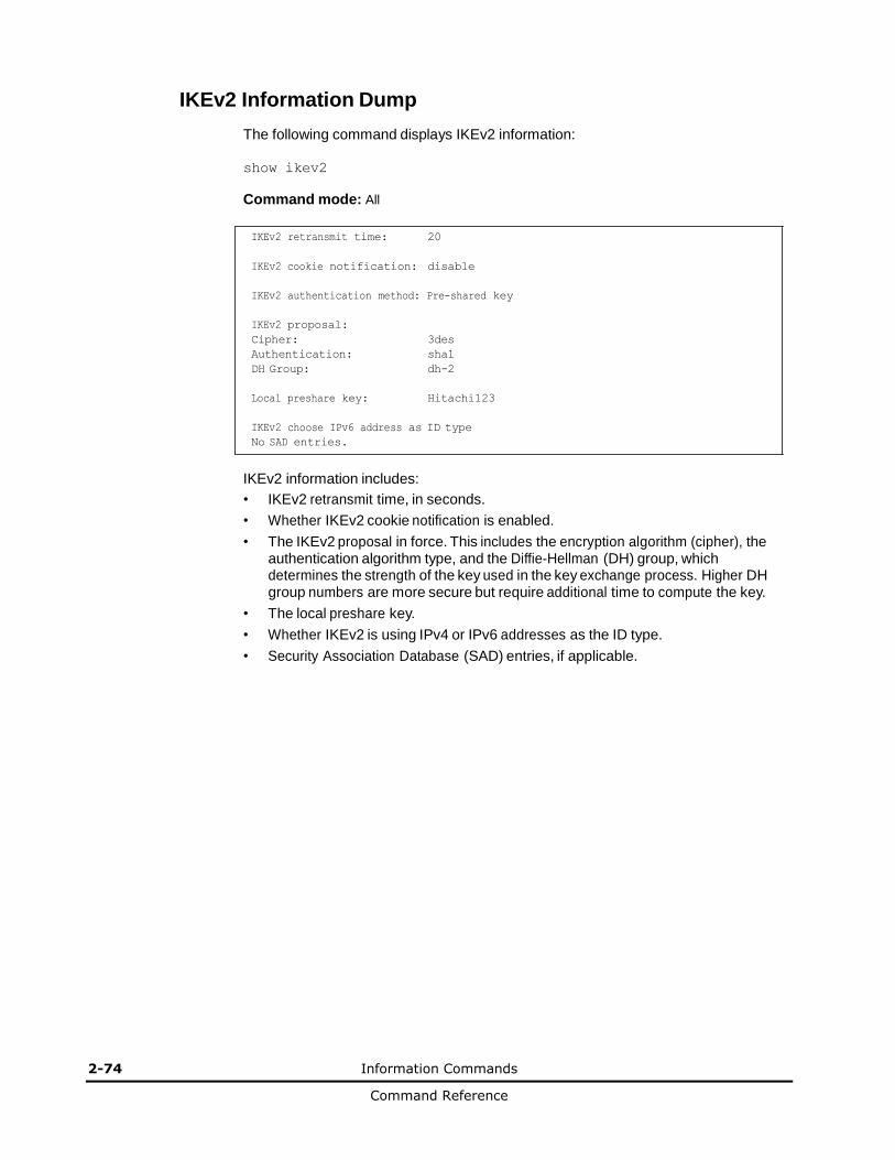
2-74 Information Commands
Command Reference
IKEv2 Information Dump
The following command displays IKEv2 information:
show ikev2
Command mode: All
IKEv2 retransmit time: 20
IKEv2 cookie notification: disable
IKEv2 authentication method: Pre-shared key
IKEv2 proposal:
Cipher: 3des
Authentication: sha1
DH Group: dh-2
Local preshare key: Hitachi123
IKEv2 choose IPv6 address as ID type
No SAD entries.
IKEv2 information includes:
• IKEv2 retransmit time, in seconds.
• Whether IKEv2 cookie notification is enabled.
• The IKEv2 proposal in force. This includes the encryption algorithm (cipher), the authentication algorithm type, and the Diffie-Hellman (DH) group, which determines the strength of the key used in the key exchange process. Higher DH group numbers are more secure but require additional time to compute the key.
• The local preshare key.
• Whether IKEv2 is using IPv4 or IPv6 addresses as the ID type.
• Security Association Database (SAD) entries, if applicable.
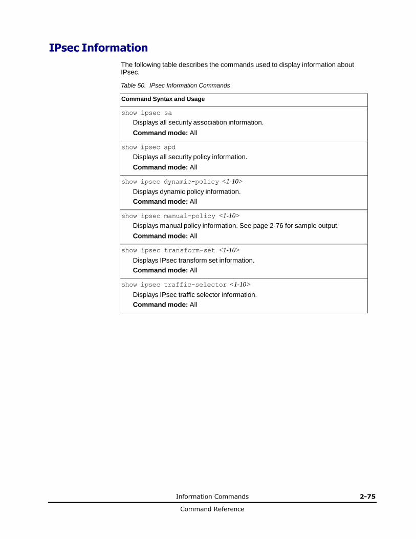
Information Commands 2-75
Command Reference
IPsec Information
The following table describes the commands used to display information about IPsec.
Table 50. IPsec Information Commands
Command Syntax and Usage
show ipsec sa
Displays all security association information.
Command mode: All
show ipsec spd
Displays all security policy information.
Command mode: All
show ipsec dynamic-policy <1-10>
Displays dynamic policy information.
Command mode: All
show ipsec manual-policy <1-10>
Displays manual policy information. See page 2-76 for sample output.
Command mode: All
show ipsec transform-set <1-10>
Displays IPsec transform set information.
Command mode: All
show ipsec traffic-selector <1-10>
Displays IPsec traffic selector information.
Command mode: All
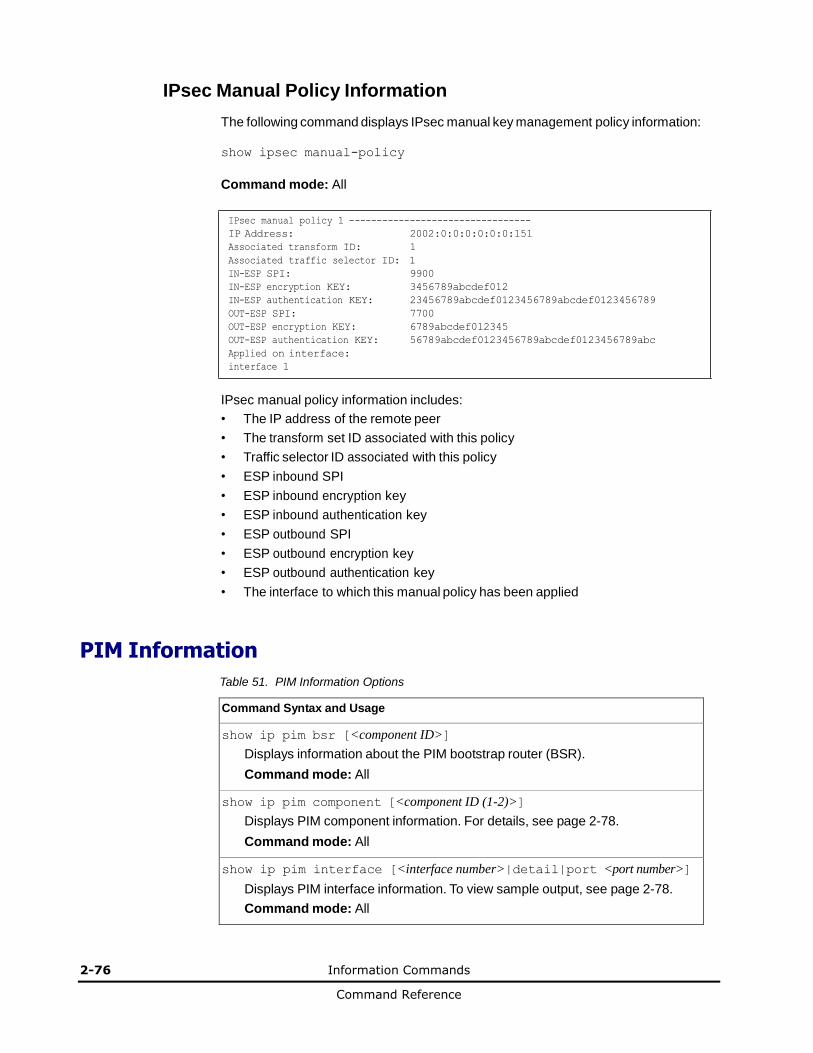
2-76 Information Commands
Command Reference
IPsec Manual Policy Information
The following command displays IPsec manual key management policy information:
show ipsec manual-policy
Command mode: All
IPsec manual policy 1 ---------------------------------
IP Address: 2002:0:0:0:0:0:0:151
Associated transform ID: 1
Associated traffic selector ID: 1
IN-ESP SPI: 9900
IN-ESP encryption KEY: 3456789abcdef012
IN-ESP authentication KEY: 23456789abcdef0123456789abcdef0123456789
OUT-ESP SPI: 7700
OUT-ESP encryption KEY: 6789abcdef012345
OUT-ESP authentication KEY: 56789abcdef0123456789abcdef0123456789abc
Applied on interface:
interface 1
IPsec manual policy information includes:
• The IP address of the remote peer
• The transform set ID associated with this policy
• Traffic selector ID associated with this policy
• ESP inbound SPI
• ESP inbound encryption key
• ESP inbound authentication key
• ESP outbound SPI
• ESP outbound encryption key
• ESP outbound authentication key
• The interface to which this manual policy has been applied
PIM Information
Table 51. PIM Information Options
Command Syntax and Usage
show ip pim bsr [<component ID>]
Displays information about the PIM bootstrap router (BSR).
Command mode: All
show ip pim component [<component ID (1-2)>]
Displays PIM component information. For details, see page 2-78.
Command mode: All
show ip pim interface [<interface number>|detail|port <port number>]
Displays PIM interface information. To view sample output, see page 2-78.
Command mode: All
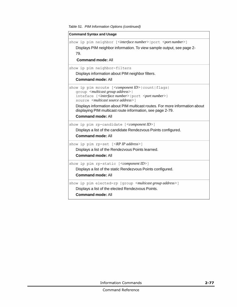
Information Commands 2-77
Command Reference
Table 51. PIM Information Options (continued)
Command Syntax and Usage
show ip pim neighbor [<interface number>|port <port number>]
Displays PIM neighbor information. To view sample output, see page 2-
79.
Command mode: All
show ip pim neighbor-filters
Displays information about PIM neighbor filters.
Command mode: All
show ip pim mroute [<component ID>|count|flags| group <multicast group address>| inteface {<interface number>|port <port number>} source <multicast source address>]
Displays information about PIM multicast routes. For more information about displaying PIM multicast route information, see page 2-79.
Command mode: All
show ip pim rp-candidate [<component ID>]
Displays a list of the candidate Rendezvous Points configured.
Command mode: All
show ip pim rp-set [<RP IP address>]
Displays a list of the Rendezvous Points learned.
Command mode: All
show ip pim rp-static [<component ID>]
Displays a list of the static Rendezvous Points configured.
Command mode: All
show ip pim elected-rp [group <multicast group address>]
Displays a list of the elected Rendezvous Points.
Command mode: All

2-78 Information Commands
Command Reference
PIM Component Information
The following command displays Protocol Independent Multicast (PIM) component information:
show ip pim component [<component ID>]
Command mode: All
PIM Component Information
---------------------------
Component-Id: 1
PIM Mode: sparse, PIM Version: 2
Elected BSR: 1.1.1.1
Candidate RP Holdtime: 100
PIM component information includes the following:
• Component ID
• Mode (sparse, dense)
• PIM Version
• Elected Bootstrap Router (BSR) address
• Candidate Rendezvous Point (RP) hold time, in seconds
PIM Interface Information
The following command displays information about PIM interfaces:
show ip pim interface
Command mode: All
Address IfName/IfId Ver/Mode Nbr Qry DR-Address DR-Prio
Count Interval ------- ----------- -------- ----- -------- ---------- -----
40.0.0.3 net4/4 2/Sparse 1 30 40.0.0.3 1
50.0.0.3 net5/5 2/Sparse 0 30 50.0.0.3 1
PIM interface information includes the following for each PIM interface:
• IP address
• Name and ID
• Version and mode
• Neighbor count
• Query interval
• Designated Router address
• Designated Router priority value
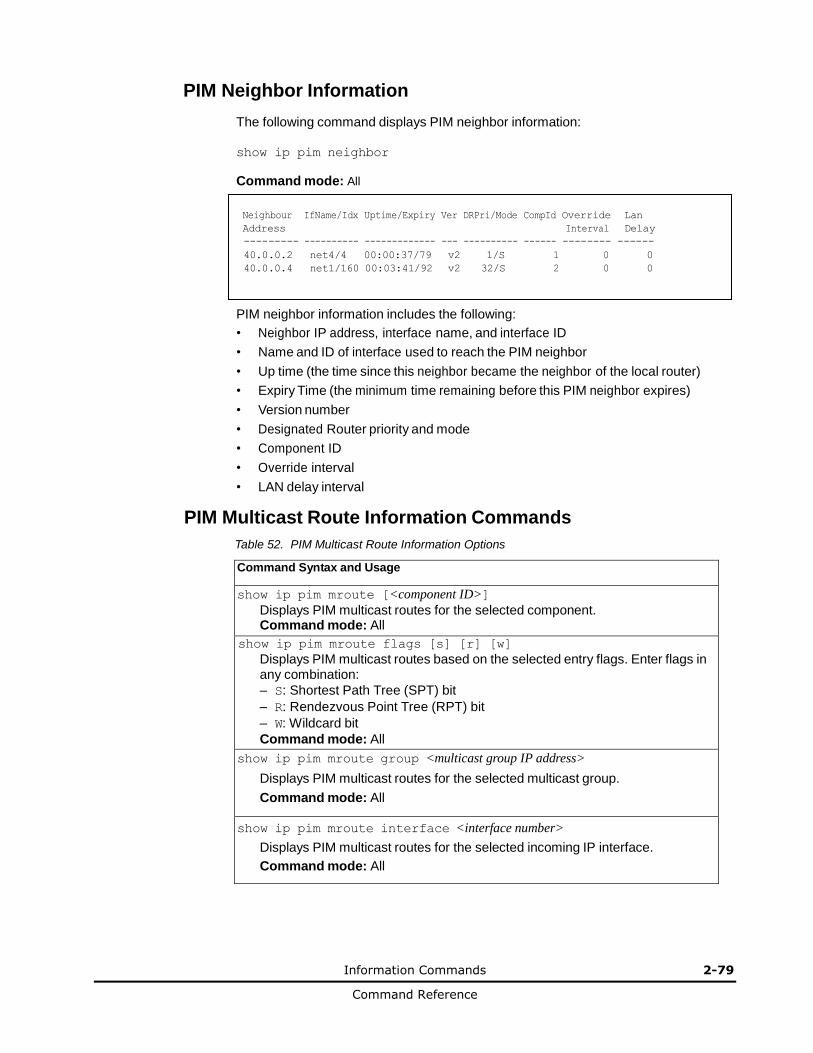
Information Commands 2-79
Command Reference
PIM Neighbor Information
The following command displays PIM neighbor information:
show ip pim neighbor
Command mode: All
Neighbour IfName/Idx Uptime/Expiry Ver DRPri/Mode CompId Override Lan
Address Interval Delay
--------- ---------- ------------- --- ---------- ------ -------- ------
40.0.0.2 net4/4 00:00:37/79 v2 1/S 1 0 0
40.0.0.4 net1/160 00:03:41/92 v2 32/S 2 0 0
PIM neighbor information includes the following:
• Neighbor IP address, interface name, and interface ID
• Name and ID of interface used to reach the PIM neighbor
• Up time (the time since this neighbor became the neighbor of the local router)
• Expiry Time (the minimum time remaining before this PIM neighbor expires)
• Version number
• Designated Router priority and mode
• Component ID
• Override interval
• LAN delay interval
PIM Multicast Route Information Commands
Table 52. PIM Multicast Route Information Options
Command Syntax and Usage
show ip pim mroute [<component ID>]
Displays PIM multicast routes for the selected component. Command mode: All
show ip pim mroute flags [s] [r] [w]
Displays PIM multicast routes based on the selected entry flags. Enter flags in any combination:
– S: Shortest Path Tree (SPT) bit
– R: Rendezvous Point Tree (RPT) bit
– W: Wildcard bit
Command mode: All
show ip pim mroute group <multicast group IP address>
Displays PIM multicast routes for the selected multicast group.
Command mode: All
show ip pim mroute interface <interface number>
Displays PIM multicast routes for the selected incoming IP interface.
Command mode: All

2-80 Information Commands
Command Reference
Table 52. PIM Multicast Route Information Options (continued)
Command Syntax and Usage
show ip pim mroute source <multicast source IP address>
Displays PIM multicast routes for the selected source IP address.
Command mode: All
show ip pim mroute count
Displays a count of PIM multicast routes of each type.
Command mode: All
show ip pim mroute
Displays information about all PIM multicast routes.
Command mode: All
PIM Multicast Route Information
The following command displays PIM multicast route information:
show ip pim mroute
Command mode: All
IP Multicast Routing Table
--------------------------
Route Flags S: SPT Bit W: Wild Card Bit R: RPT Bit
Timers: Uptime/Expires
(8.8.8.111, 224.2.2.100) ,00:42:03/00:01:11
Incoming Interface : net44 ,RPF nbr : 44.44.44.1 ,Route Flags : S
Outgoing InterfaceList :
net17, Forwarding/Sparse ,00:42:03/---
(*, 224.2.2.100) ,00:45:15/--- ,RP : 88.88.88.2
Incoming Interface : net5 ,RPF nbr : 5.5.5.2 ,Route Flags : WR
Outgoing InterfaceList :
net17, Forwarding/Sparse ,00:45:15/---
Total number of (*,G) entries : 1
Total number of (S,G) entries : 1
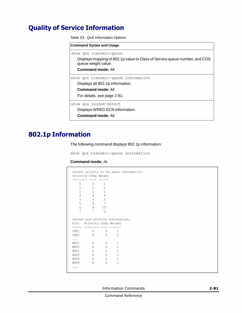
Information Commands 2-81
Command Reference
Quality of Service Information
Table 53. QoS Information Options
Command Syntax and Usage
show qos transmit-queue
Displays mapping of 802.1p value to Class of Service queue number, and COS queue weight value.
Command mode: All
show qos transmit-queue information
Displays all 802.1p information.
Command mode: All
For details, see page 2-81.
show qos random-detect
Displays WRED ECN information.
Command mode: All
802.1p Information
The following command displays 802.1p information:
show qos transmit-queue information
Command mode: All
Current priority to COS queue information:
Priority COSq Weight
-------- ---- ------
0 0 1
1 1 2
2 2 3
3 3 4
4 4 5
5 5 7
6 6 15
7 7 0
Current port priority information:
Port Priority COSq Weight
----- -------- ---- ------
INT1 0 0 1
INT2 0 0 1
... MGT1 0 0 1
MGT2 0 0 1
EXT1 0 0 1
EXT2 0 0 1
EXT3 0 0 1
EXT4 0 0 1
...
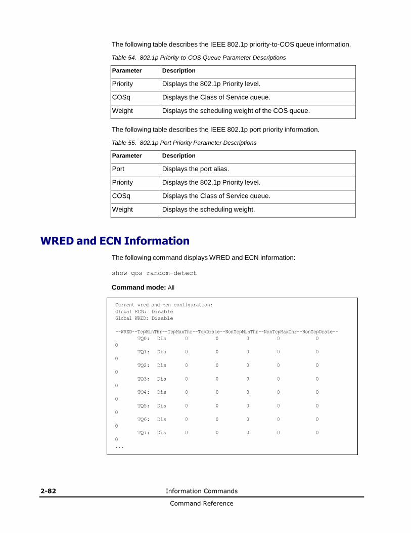
2-82 Information Commands
Command Reference
The following table describes the IEEE 802.1p priority-to-COS queue information.
Table 54. 802.1p Priority-to-COS Queue Parameter Descriptions
Parameter Description
Priority Displays the 802.1p Priority level.
COSq Displays the Class of Service queue.
Weight Displays the scheduling weight of the COS queue.
The following table describes the IEEE 802.1p port priority information.
Table 55. 802.1p Port Priority Parameter Descriptions
Parameter Description
Port Displays the port alias.
Priority Displays the 802.1p Priority level.
COSq Displays the Class of Service queue.
Weight Displays the scheduling weight.
WRED and ECN Information
The following command displays WRED and ECN information:
show qos random-detect
Command mode: All
Current wred and ecn configuration:
Global ECN: Disable
Global WRED: Disable
--WRED--TcpMinThr--TcpMaxThr--TcpDrate--NonTcpMinThr--NonTcpMaxThr--NonTcpDrate--
TQ0: Dis 0 0 0 0 0
0 TQ1: Dis 0 0 0 0 0
0 TQ2: Dis 0 0 0 0 0
0 TQ3: Dis 0 0 0 0 0
0 TQ4: Dis 0 0 0 0 0
0 TQ5: Dis 0 0 0 0 0
0 TQ6: Dis 0 0 0 0 0
0 TQ7: Dis 0 0 0 0 0
0 ...
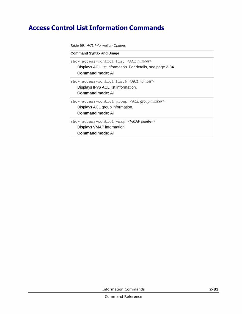
Information Commands 2-83
Command Reference
Access Control List Information Commands
Table 56. ACL Information Options
Command Syntax and Usage
show access-control list <ACL number>
Displays ACL list information. For details, see page 2-84.
Command mode: All
show access-control list6 <ACL number>
Displays IPv6 ACL list information.
Command mode: All
show access-control group <ACL group number>
Displays ACL group information.
Command mode: All
show access-control vmap <VMAP number>
Displays VMAP information.
Command mode: All
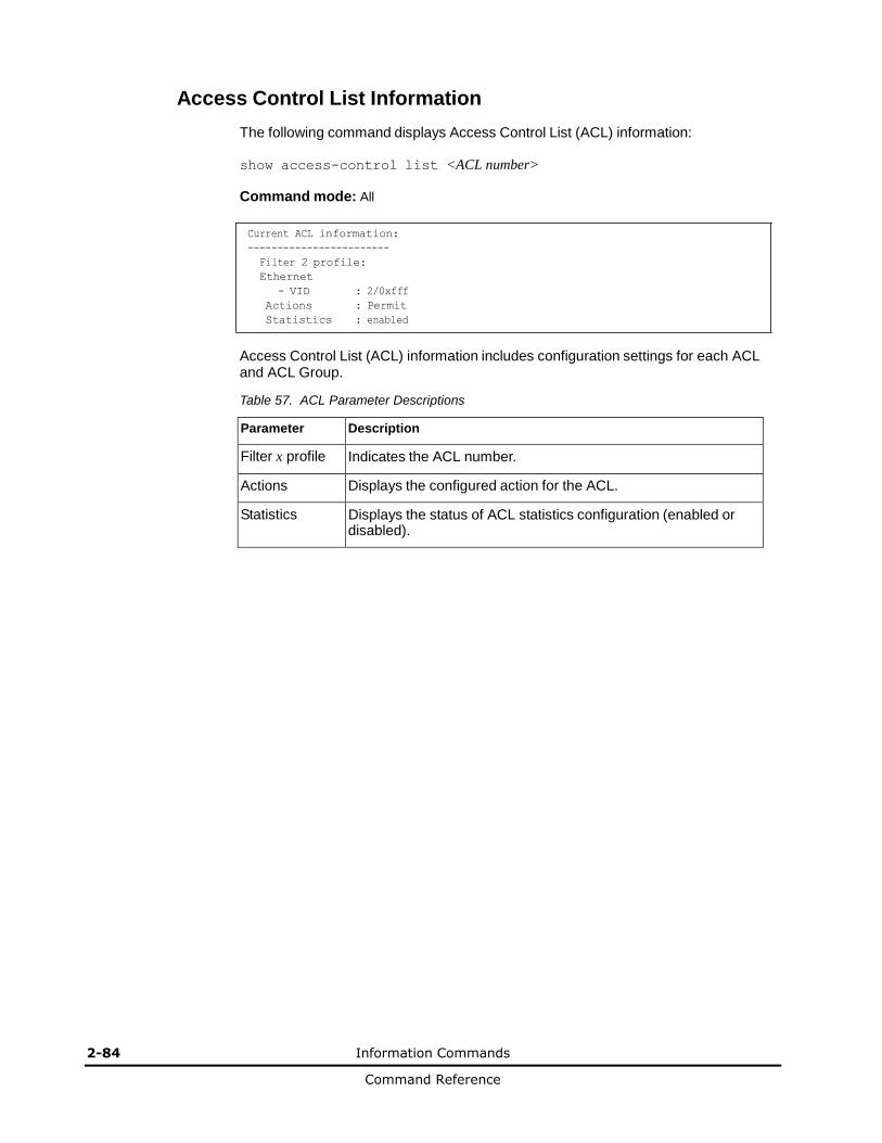
2-84 Information Commands
Command Reference
Access Control List Information
The following command displays Access Control List (ACL) information:
show access-control list <ACL number>
Command mode: All
Current ACL information:
------------------------
Filter 2 profile:
Ethernet
- VID : 2/0xfff
Actions : Permit
Statistics : enabled
Access Control List (ACL) information includes configuration settings for each ACL and ACL Group.
Table 57. ACL Parameter Descriptions
Parameter Description
Filter x profile Indicates the ACL number.
Actions Displays the configured action for the ACL.
Statistics Displays the status of ACL statistics configuration (enabled or disabled).
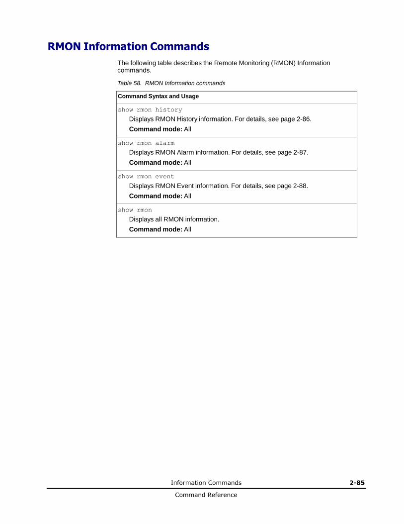
Information Commands 2-85
Command Reference
RMON Information Commands
The following table describes the Remote Monitoring (RMON) Information commands.
Table 58. RMON Information commands
Command Syntax and Usage
show rmon history
Displays RMON History information. For details, see page 2-86.
Command mode: All
show rmon alarm
Displays RMON Alarm information. For details, see page 2-87.
Command mode: All
show rmon event
Displays RMON Event information. For details, see page 2-88.
Command mode: All
show rmon
Displays all RMON information.
Command mode: All

2-86 Information Commands
Command Reference
RMON History Information
The following command displays RMON History information:
show rmon history
Command mode: All
RMON History group configuration:
Index IFOID Interval Rbnum Gbnum
----- ------------------------------ -------- ----- -----
1 1.3.6.1.2.1.2.2.1.1.24 30 5 5
2 1.3.6.1.2.1.2.2.1.1.22 30 5 5
3 1.3.6.1.2.1.2.2.1.1.20 30 5 5
4 1.3.6.1.2.1.2.2.1.1.19 30 5 5
5 1.3.6.1.2.1.2.2.1.1.24 1800 5 5
Index Owner
----- ---------------------------------------------
1 dan
The following table describes the RMON History Information parameters.
Table 59. RMON History Parameter Descriptions
Parameter Description
Index Displays the index number that identifies each history instance.
IFOID Displays the MIB Object Identifier.
Interval Displays the time interval for each sampling bucket.
Rbnum Displays the number of requested buckets, which is the number of data slots into which data is to be saved.
Gbnum Displays the number of granted buckets that may hold sampled data.
Owner Displays the owner of the history instance.
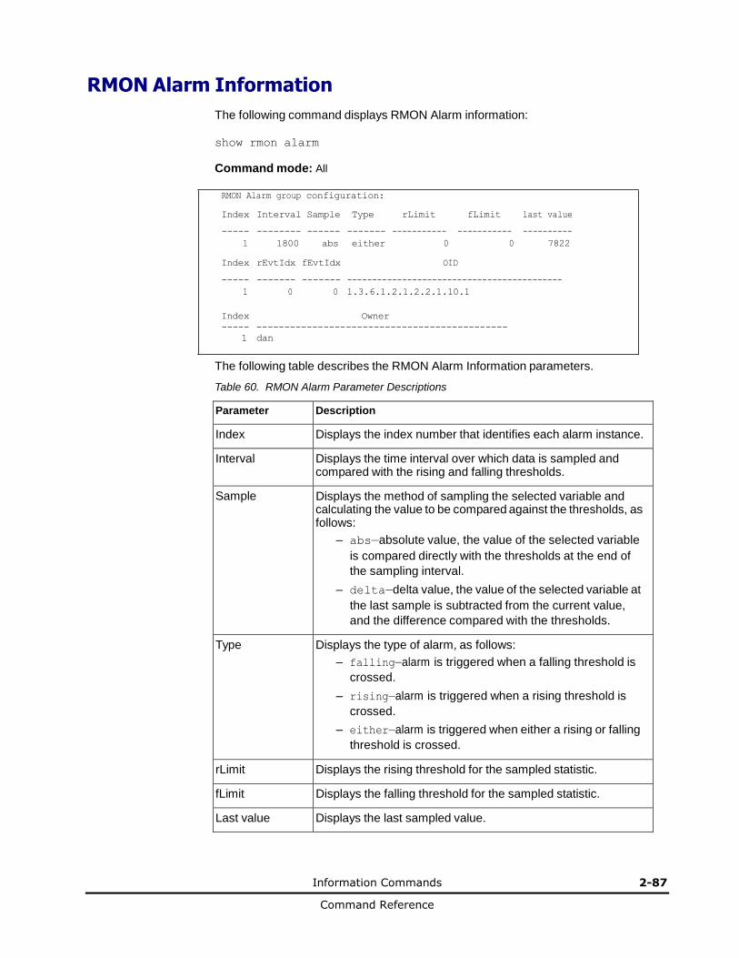
Information Commands 2-87
Command Reference
RMON Alarm Information
The following command displays RMON Alarm information:
show rmon alarm
Command mode: All
RMON Alarm group configuration:
Index Interval Sample Type rLimit fLimit last value
----- -------- ------ ------- ----------- ----------- ----------
1 1800 abs either 0 0 7822
Index rEvtIdx fEvtIdx OID
----- ------- ------- -------------------------------------------
1 0 0 1.3.6.1.2.1.2.2.1.10.1
Index Owner
----- ---------------------------------------------
1 dan
The following table describes the RMON Alarm Information parameters.
Table 60. RMON Alarm Parameter Descriptions
Parameter Description
Index Displays the index number that identifies each alarm instance.
Interval Displays the time interval over which data is sampled and compared with the rising and falling thresholds.
Sample Displays the method of sampling the selected variable and calculating the value to be compared against the thresholds, as follows:
– abs—absolute value, the value of the selected variable
is compared directly with the thresholds at the end of
the sampling interval.
– delta—delta value, the value of the selected variable at
the last sample is subtracted from the current value,
and the difference compared with the thresholds.
Type Displays the type of alarm, as follows:
– falling—alarm is triggered when a falling threshold is
crossed.
– rising—alarm is triggered when a rising threshold is
crossed.
– either—alarm is triggered when either a rising or falling
threshold is crossed.
rLimit Displays the rising threshold for the sampled statistic.
fLimit Displays the falling threshold for the sampled statistic.
Last value Displays the last sampled value.
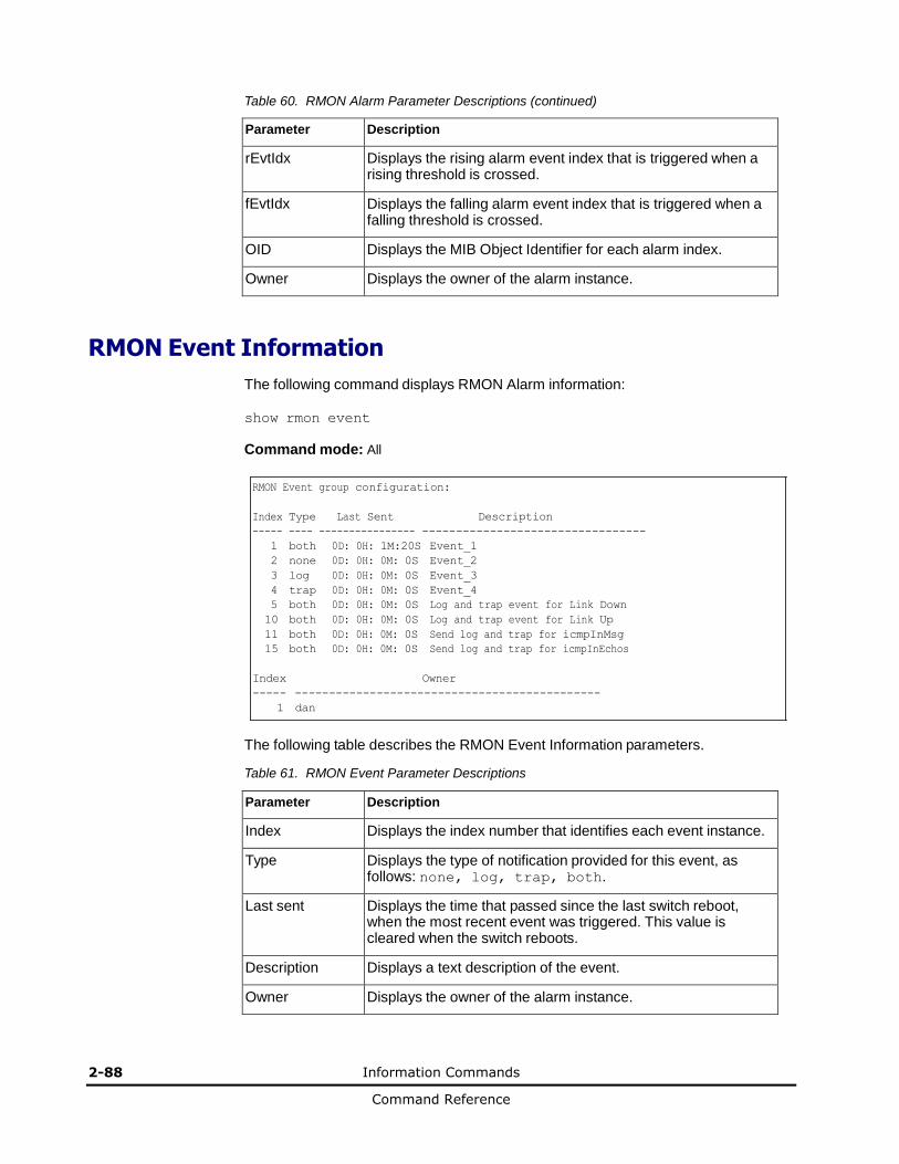
2-88 Information Commands
Command Reference
Table 60. RMON Alarm Parameter Descriptions (continued)
Parameter Description
rEvtIdx Displays the rising alarm event index that is triggered when a rising threshold is crossed.
fEvtIdx Displays the falling alarm event index that is triggered when a falling threshold is crossed.
OID Displays the MIB Object Identifier for each alarm index.
Owner Displays the owner of the alarm instance.
RMON Event Information
The following command displays RMON Alarm information:
show rmon event
Command mode: All
RMON Event group configuration:
Index Type Last Sent Description
----- ---- ---------------- ---------------------------------
1 both 0D: 0H: 1M:20S Event_1
2 none 0D: 0H: 0M: 0S Event_2
3 log 0D: 0H: 0M: 0S Event_3
4 trap 0D: 0H: 0M: 0S Event_4
5 both 0D: 0H: 0M: 0S Log and trap event for Link Down
10 both 0D: 0H: 0M: 0S Log and trap event for Link Up
11 both 0D: 0H: 0M: 0S Send log and trap for icmpInMsg
15 both 0D: 0H: 0M: 0S Send log and trap for icmpInEchos
Index Owner
----- ---------------------------------------------
1 dan
The following table describes the RMON Event Information parameters.
Table 61. RMON Event Parameter Descriptions
Parameter Description
Index Displays the index number that identifies each event instance.
Type Displays the type of notification provided for this event, as follows: none, log, trap, both.
Last sent Displays the time that passed since the last switch reboot, when the most recent event was triggered. This value is cleared when the switch reboots.
Description Displays a text description of the event.
Owner Displays the owner of the alarm instance.
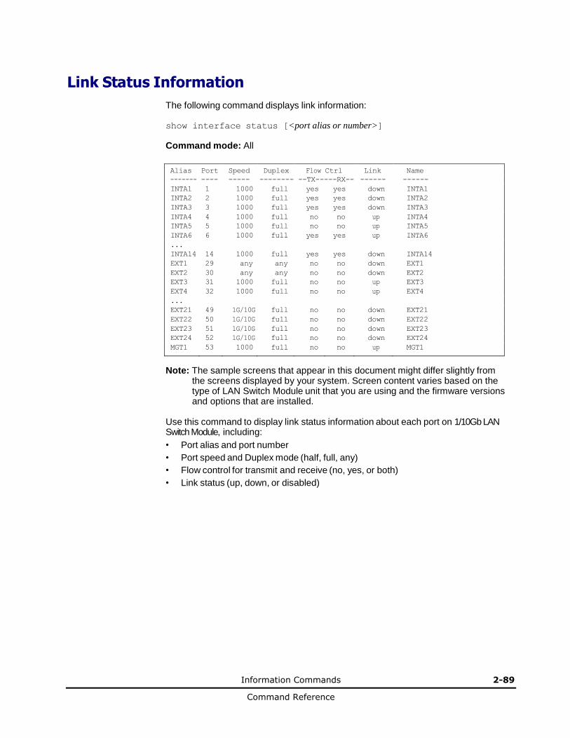
Information Commands 2-89
Command Reference
Link Status Information
The following command displays link information:
show interface status [<port alias or number>]
Command mode: All
Alias Port Speed Duplex Flow Ctrl Link Name
------- ---- ----- -------- --TX-----RX-- ------ ------
INTA1 1 1000 full yes yes down INTA1
INTA2 2 1000 full yes yes down INTA2
INTA3 3 1000 full yes yes down INTA3
INTA4 4 1000 full no no up INTA4
INTA5 5 1000 full no no up INTA5
INTA6 6 1000 full yes yes up INTA6
... INTA14 14 1000 full yes yes down INTA14
EXT1 29 any any no no down EXT1
EXT2 30 any any no no down EXT2
EXT3 31 1000 full no no up EXT3
EXT4 32 1000 full no no up EXT4
... EXT21 49 1G/10G full no no down EXT21
EXT22 50 1G/10G full no no down EXT22
EXT23 51 1G/10G full no no down EXT23
EXT24 52 1G/10G full no no down EXT24
MGT1 53 1000 full no no up MGT1
Note: The sample screens that appear in this document might differ slightly from
the screens displayed by your system. Screen content varies based on the type of LAN Switch Module unit that you are using and the firmware versions and options that are installed.
Use this command to display link status information about each port on 1/10Gb LAN Switch Module, including:
• Port alias and port number
• Port speed and Duplex mode (half, full, any)
• Flow control for transmit and receive (no, yes, or both)
• Link status (up, down, or disabled)
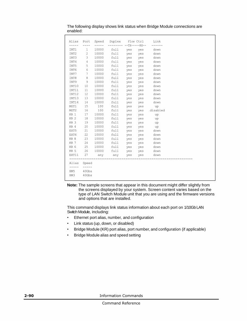
2-90 Information Commands
Command Reference
The following display shows link status when Bridge Module connections are enabled:
Alias Port Speed Duplex Flow Ctrl Link
----- ---- ----- -------- --TX-----RX-- ------
INT1 1 10000 full yes yes down
INT2 2 10000 full yes yes down
INT3 3 10000 full yes yes down
INT4 4 10000 full yes yes down
INT5 5 10000 full yes yes down
INT6 6 10000 full yes yes down
INT7 7 10000 full yes yes down
INT8 8 10000 full yes yes down
INT9 9 10000 full yes yes down
INT10 10 10000 full yes yes down
INT11 11 10000 full yes yes down
INT12 12 10000 full yes yes down
INT13 13 10000 full yes yes down
INT14 14 10000 full yes yes down
MGT1 15 100 full yes yes up
MGT2 16 100 full yes yes disabled
KR 1 17 10000 full yes yes up
KR 2 18 10000 full yes yes up
KR 3 19 10000 full yes yes up
KR 4 20 10000 full yes yes up
EXT5 21 10000 full yes yes down
EXT6 22 10000 full yes yes down
KR 8 23 10000 full yes yes down
KR 7 24 10000 full yes yes down
KR 6 25 10000 full yes yes down
KR 5 26 10000 full yes yes down
EXT11 27 any any yes yes down
------------------------------------------------------------------
Alias Speed
----- -----
BM5 40Gbs
BM3 40Gbs
Note: The sample screens that appear in this document might differ slightly from the screens displayed by your system. Screen content varies based on the type of LAN Switch Module unit that you are using and the firmware versions and options that are installed.
This command displays link status information about each port on 1/10Gb LAN Switch Module, including:
• Ethernet port alias, number, and configuration
• Link status (up, down, or disabled)
• Bridge Module (KR) port alias, port number, and configuration (if applicable)
• Bridge Module alias and speed setting
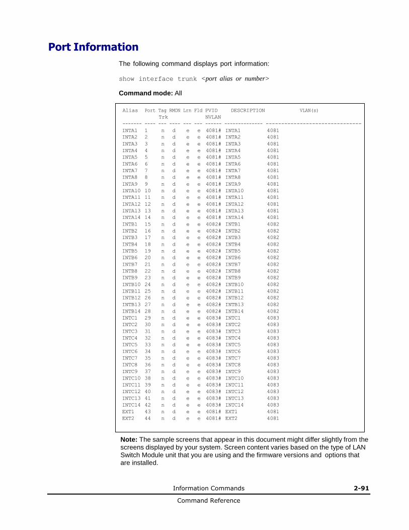
Information Commands 2-91
Command Reference
Port Information
The following command displays port information:
show interface trunk <port alias or number>
Command mode: All
Alias Port Tag RMON Lrn Fld PVID DESCRIPTION VLAN(s)
Trk NVLAN
------- ---- --- ---- --- --- ------ -------------- -------------------------------
INTA1 1 n d e e 4081# INTA1 4081
INTA2 2 n d e e 4081# INTA2 4081
INTA3 3 n d e e 4081# INTA3 4081
INTA4 4 n d e e 4081# INTA4 4081
INTA5 5 n d e e 4081# INTA5 4081
INTA6 6 n d e e 4081# INTA6 4081
INTA7 7 n d e e 4081# INTA7 4081
INTA8 8 n d e e 4081# INTA8 4081
INTA9 9 n d e e 4081# INTA9 4081
INTA10 10 n d e e 4081# INTA10 4081
INTA11 11 n d e e 4081# INTA11 4081
INTA12 12 n d e e 4081# INTA12 4081
INTA13 13 n d e e 4081# INTA13 4081
INTA14 14 n d e e 4081# INTA14 4081
INTB1 15 n d e e 4082# INTB1 4082
INTB2 16 n d e e 4082# INTB2 4082
INTB3 17 n d e e 4082# INTB3 4082
INTB4 18 n d e e 4082# INTB4 4082
INTB5 19 n d e e 4082# INTB5 4082
INTB6 20 n d e e 4082# INTB6 4082
INTB7 21 n d e e 4082# INTB7 4082
INTB8 22 n d e e 4082# INTB8 4082
INTB9 23 n d e e 4082# INTB9 4082
INTB10 24 n d e e 4082# INTB10 4082
INTB11 25 n d e e 4082# INTB11 4082
INTB12 26 n d e e 4082# INTB12 4082
INTB13 27 n d e e 4082# INTB13 4082
INTB14 28 n d e e 4082# INTB14 4082
INTC1 29 n d e e 4083# INTC1 4083
INTC2 30 n d e e 4083# INTC2 4083
INTC3 31 n d e e 4083# INTC3 4083
INTC4 32 n d e e 4083# INTC4 4083
INTC5 33 n d e e 4083# INTC5 4083
INTC6 34 n d e e 4083# INTC6 4083
INTC7 35 n d e e 4083# INTC7 4083
INTC8 36 n d e e 4083# INTC8 4083
INTC9 37 n d e e 4083# INTC9 4083
INTC10 38 n d e e 4083# INTC10 4083
INTC11 39 n d e e 4083# INTC11 4083
INTC12 40 n d e e 4083# INTC12 4083
INTC13 41 n d e e 4083# INTC13 4083
INTC14 42 n d e e 4083# INTC14 4083
EXT1 43 n d e e 4081# EXT1 4081
EXT2 44 n d e e 4081# EXT2 4081
Note: The sample screens that appear in this document might differ slightly from the screens displayed by your system. Screen content varies based on the type of LAN Switch Module unit that you are using and the firmware versions and options that are installed.

2-92 Information Commands
Command Reference
Port information includes:
• Port alias and number
• Whether the port uses VLAN tagging or not (y or n)
• Whether the port uses PVID/Native-VLAN tagging or not (y or n)
• Whether the port uses PVID ingress tagging or not (y or n)
• Whether the port is internal, external or used for management
• Whether the port has Remote Monitoring (RMON) enabled
• Whether the port has FDB Learning enabled (Lrn)
• Whether the port has Port Flooding enabled (Fld)
• Port VLAN ID (PVID/Native-VLAN)
• Port description
• VLAN membership

Information Commands 2-93
Command Reference
Port Transceiver Status
The following command displays the status of the transceiver module on each external port:
show interface transceiver
Command mode: All ***
Port Link Transceiver Vendor Part Approve
---------------- ----- -------------- ---------------- ---------------- --------
49 EXT21 Down SX SFP Blade Network BN-CKM-S-SX Approved
50 EXT22 LINK 3m DAC BLADE NETWORK BN-SP-CBL-3M Accepted
51 EXT23 LINK SR SFP+ Blade Network BN-CKM-SP-SR Approved
52 EXT24 LINK SR SFP+ Blade Network BN-CKM-SP-SR Approved
This command displays information about the transceiver module on each port, as follows:
• Port number and media type
• Link status
• Transceiver detail
• Vendor information
• Part number
• Approval state
Use the following command to display extended transceiver information:
show interface port <port number> transceiver details
Command mode: All
Port TX Link TXFlt Volts DegsC TXuW RXuW Transceiver Approve
---------------- --- ----- ----- ----- ----- ----- ----- -------------- --------
49 EXT21 Ena Down NoFlt 3.24 40.0 287.2 0.0 SX SFP Approved
Blade Network Part:BN-CKM-S-SX Date:110225 S/N:BNTM1108QB
This command displays detailed information about the transceiver module, as follows:
• Port number and media type
• TX: Transmission status
• TXflt: Transmission fault indicator
• Volts: Power usage, in volts
• DegsC: Temperature, in degrees centigrade
• TXuW: Transmit power, in micro-watts
• RXuW: Receive power, in micro-watts
• Media type (LX, LR, SX, SR)
• Approval status
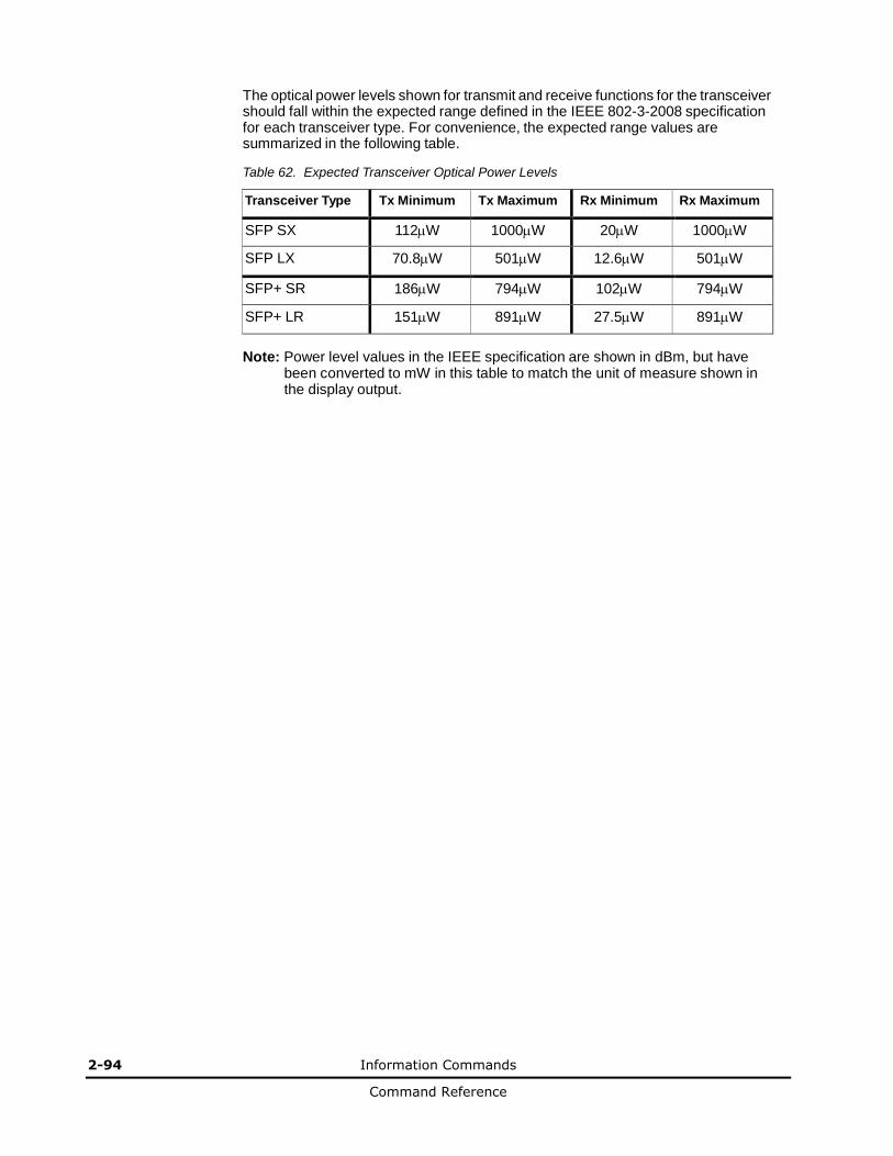
2-94 Information Commands
Command Reference
The optical power levels shown for transmit and receive functions for the transceiver should fall within the expected range defined in the IEEE 802-3-2008 specification for each transceiver type. For convenience, the expected range values are summarized in the following table.
Table 62. Expected Transceiver Optical Power Levels
Transceiver Type Tx Minimum Tx Maximum Rx Minimum Rx Maximum
SFP SX 112W 1000W 20W 1000W
SFP LX 70.8W 501W 12.6W 501W
SFP+ SR 186W 794W 102W 794W
SFP+ LR 151W 891W 27.5W 891W
Note: Power level values in the IEEE specification are shown in dBm, but have been converted to mW in this table to match the unit of measure shown in the display output.
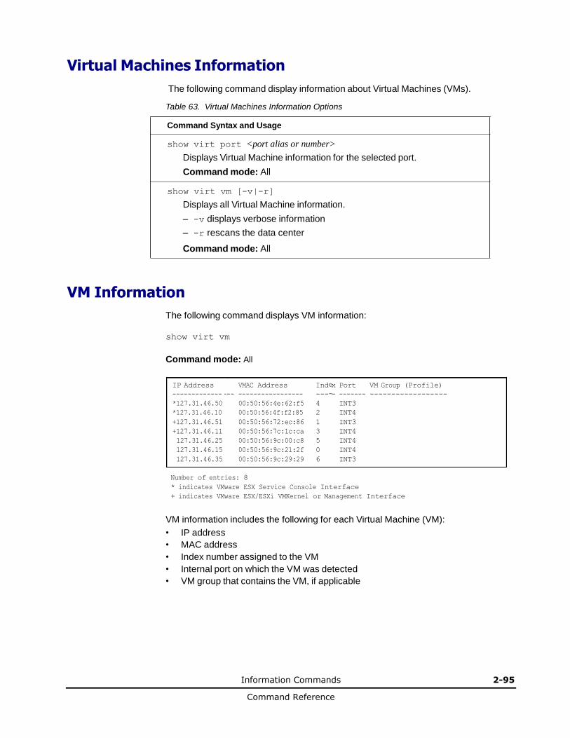
Information Commands 2-95
Command Reference
IP Address VMAC Address Ind x Port VM Group (Profile)
------------- --- ----------------- --- - ------- ------------------
*127.31.46.50 00:50:56:4e:62:f5 4 INT3
*127.31.46.10 00:50:56:4f:f2:85 2 INT4
+127.31.46.51 00:50:56:72:ec:86 1 INT3
+127.31.46.11 00:50:56:7c:1c:ca 3 INT4
127.31.46.25 00:50:56:9c:00:c8 5 INT4
127.31.46.15 00:50:56:9c:21:2f 0 INT4
127.31.46.35 00:50:56:9c:29:29 6 INT3
Virtual Machines Information
The following command display information about Virtual Machines (VMs).
Table 63. Virtual Machines Information Options
Command Syntax and Usage
show virt port <port alias or number>
Displays Virtual Machine information for the selected port.
Command mode: All
show virt vm [-v|-r]
Displays all Virtual Machine information.
– -v displays verbose information
– -r rescans the data center
Command mode: All
VM Information
The following command displays VM information:
show virt vm
Command mode: All
e
-
Number of entries: 8
* indicates VMware ESX Service Console Interface
+ indicates VMware ESX/ESXi VMKernel or Management Interface
VM information includes the following for each Virtual Machine (VM):
• IP address
• MAC address
• Index number assigned to the VM
• Internal port on which the VM was detected
• VM group that contains the VM, if applicable
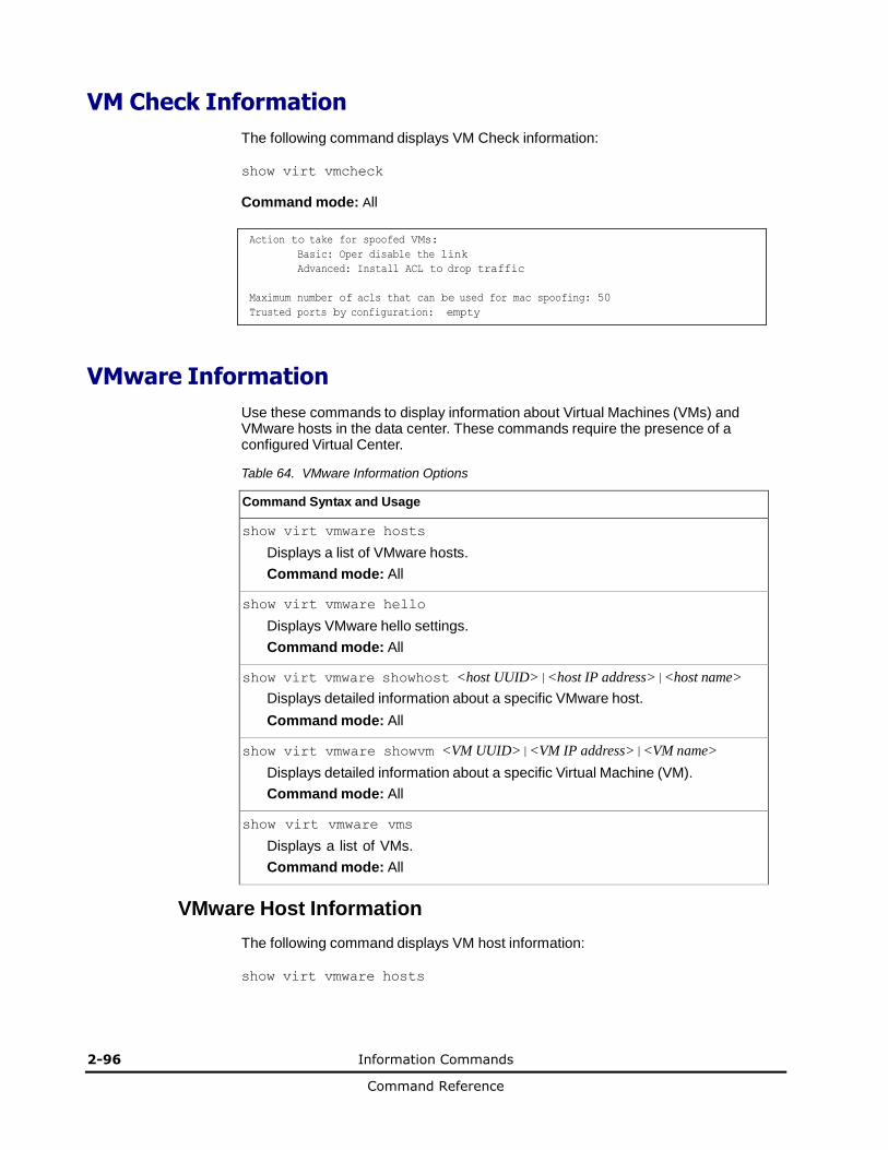
2-96 Information Commands
Command Reference
VM Check Information
The following command displays VM Check information:
show virt vmcheck
Command mode: All
Action to take for spoofed VMs:
Basic: Oper disable the link
Advanced: Install ACL to drop traffic
Maximum number of acls that can be used for mac spoofing: 50
Trusted ports by configuration: empty
VMware Information
Use these commands to display information about Virtual Machines (VMs) and VMware hosts in the data center. These commands require the presence of a configured Virtual Center.
Table 64. VMware Information Options
Command Syntax and Usage
show virt vmware hosts
Displays a list of VMware hosts.
Command mode: All
show virt vmware hello
Displays VMware hello settings.
Command mode: All
show virt vmware showhost <host UUID>|<host IP address>|<host name>
Displays detailed information about a specific VMware host.
Command mode: All
show virt vmware showvm <VM UUID>|<VM IP address>|<VM name>
Displays detailed information about a specific Virtual Machine (VM).
Command mode: All
show virt vmware vms
Displays a list of VMs.
Command mode: All
VMware Host Information
The following command displays VM host information:
show virt vmware hosts
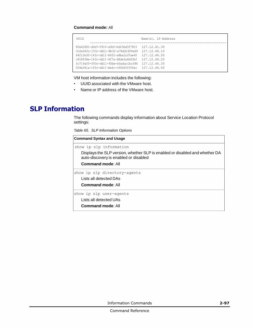
Information Commands 2-97
Command Reference
Command mode: All
UUID Name(s), IP Address
-----------------------------------------------------------------------
80a42681-d0e5-5910-a0bf-bd23bd3f7803 127.12.41.30
3c2e063c-153c-dd11-8b32-a78dd1909a69 127.12.46.10
64f1fe30-143c-dd11-84f2-a8ba2cd7ae40 127.12.44.50
c818938e-143c-dd11-9f7a-d8defa4b83bf 127.12.46.20
fc719af0-093c-dd11-95be-b0adac1bcf86 127.12.46.30
009a581a-143c-dd11-be4c-c9fb65ff04ec 127.12.46.40
VM host information includes the following:
• UUID associated with the VMware host.
• Name or IP address of the VMware host.
SLP Information
The following commands display information about Service Location Protocol settings:
Table 65. SLP Information Options
Command Syntax and Usage
show ip slp information
Displays the SLP version, whether SLP is enabled or disabled and whether DA auto-discovery is enabled or disabled
Command mode: All
show ip slp directory-agents
Lists all detected DAs
Command mode: All
show ip slp user-agents
Lists all detected UAs
Command mode: All

2-98 Information Commands
Command Reference
Information Dump
The following command dumps switch information:
show information-dump
Command mode: All
Use the dump command to dump all switch information available (10K or more, depending on your configuration). This data is useful for tuning and debugging switch performance.
If you want to capture dump data to a file, set your communication software on your workstation to capture session data prior to issuing the dump commands.
3
Statistics Commands 3-1
Command Reference
Statistics Commands
This chapter discusses how to use the command line interface to display switch
statistics.
Statistics Commands
Port Statistics
Trunk Group Statistics
Layer 2 Statistics
Layer 3 Statistics
Management Processor Statistics
Access Control List Statistics
ACL Meter Statistics
SNMP Statistics
NTP Statistics
SLP Statistics
Statistics Dump
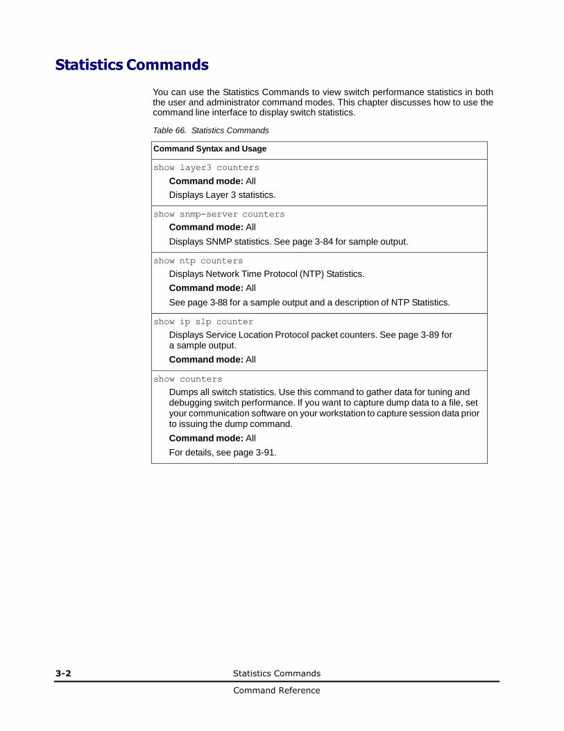
3-2 Statistics Commands
Command Reference
Statistics Commands
You can use the Statistics Commands to view switch performance statistics in both the user and administrator command modes. This chapter discusses how to use the command line interface to display switch statistics.
Table 66. Statistics Commands
Command Syntax and Usage
show layer3 counters
Command mode: All
Displays Layer 3 statistics.
show snmp-server counters
Command mode: All
Displays SNMP statistics. See page 3-84 for sample output.
show ntp counters
Displays Network Time Protocol (NTP) Statistics.
Command mode: All
See page 3-88 for a sample output and a description of NTP Statistics.
show ip slp counter
Displays Service Location Protocol packet counters. See page 3-89 for a sample output.
Command mode: All
show counters
Dumps all switch statistics. Use this command to gather data for tuning and debugging switch performance. If you want to capture dump data to a file, set your communication software on your workstation to capture session data prior to issuing the dump command.
Command mode: All
For details, see page 3-91.
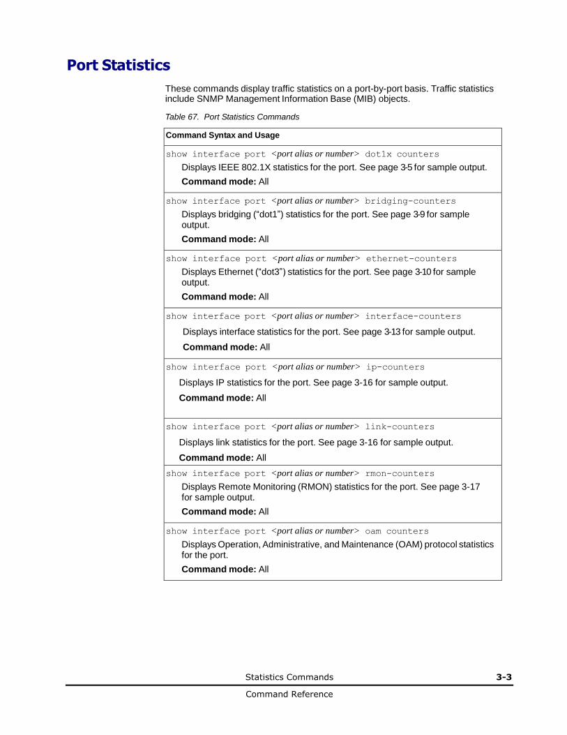
Statistics Commands 3-3
Command Reference
Port Statistics
These commands display traffic statistics on a port-by-port basis. Traffic statistics include SNMP Management Information Base (MIB) objects.
Table 67. Port Statistics Commands
Command Syntax and Usage
show interface port <port alias or number> dot1x counters
Displays IEEE 802.1X statistics for the port. See page 3-5 for sample output.
Command mode: All
show interface port <port alias or number> bridging-counters
Displays bridging (“dot1”) statistics for the port. See page 3-9 for sample output.
Command mode: All
show interface port <port alias or number> ethernet-counters
Displays Ethernet (“dot3”) statistics for the port. See page 3-10 for sample output.
Command mode: All
show interface port <port alias or number> interface-counters
Displays interface statistics for the port. See page 3-13 for sample output.
Command mode: All
show interface port <port alias or number> ip-counters
Displays IP statistics for the port. See page 3-16 for sample output.
Command mode: All
show interface port <port alias or number> link-counters
Displays link statistics for the port. See page 3-16 for sample output.
Command mode: All
show interface port <port alias or number> rmon-counters
Displays Remote Monitoring (RMON) statistics for the port. See page 3-17 for sample output.
Command mode: All
show interface port <port alias or number> oam counters
Displays Operation, Administrative, and Maintenance (OAM) protocol statistics for the port.
Command mode: All
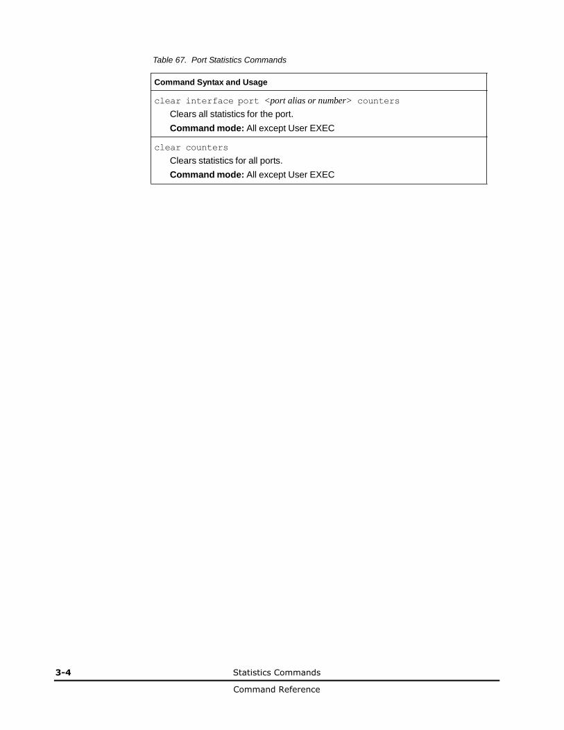
3-4 Statistics Commands
Command Reference
Table 67. Port Statistics Commands
Command Syntax and Usage
clear interface port <port alias or number> counters
Clears all statistics for the port.
Command mode: All except User EXEC
clear counters
Clears statistics for all ports.
Command mode: All except User EXEC

Statistics Commands 3-5
Command Reference
802.1X Authenticator Statistics
Use the following command to display the 802.1X authenticator statistics of the selected port:
show interface port <port alias or number> dot1x counters
Command mode: All
Authenticator Statistics:
eapolFramesRx = 925
eapolFramesTx = 3201
eapolStartFramesRx = 2
eapolLogoffFramesRx = 0
eapolRespIdFramesRx = 463
eapolRespFramesRx = 460
eapolReqIdFramesTx = 1820
eapolReqFramesTx = 1381
invalidEapolFramesRx = 0
eapLengthErrorFramesRx = 0
lastEapolFrameVersion = 1
lastEapolFrameSource = 00:01:02:45:ac:51
Table 68. 802.1X Authenticator Statistics of a Port
Statistics Description
eapolFramesRx Total number of EAPOL frames received
eapolFramesTx Total number of EAPOL frames transmitted
eapolStartFramesRx Total number of EAPOL Start frames received
eapolLogoffFramesRx Total number of EAPOL Logoff frames received
eapolRespIdFramesRx Total number of EAPOL Response Identity frames received
eapolRespFramesRx Total number of Response frames received
eapolReqIdFramesTx Total number of Request Identity frames transmitted
eapolReqFramesTx Total number of Request frames transmitted
invalidEapolFramesRx Total number of invalid EAPOL frames received
eapLengthErrorFramesRx Total number of EAP length error frames received
lastEapolFrameVersion The protocol version number carried in the most recently received EAPOL frame.
lastEapolFrameSource The source MAC address carried in the most recently received EAPOL frame.
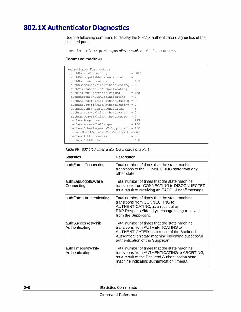
3-6 Statistics Commands
Command Reference
802.1X Authenticator Diagnostics
Use the following command to display the 802.1X authenticator diagnostics of the selected port:
show interface port <port alias or number> dot1x counters
Command mode: All
Authenticator Diagnostics:
authEntersConnecting = 1820
authEapLogoffsWhileConnecting = 0
authEntersAuthenticating = 463
authSuccessesWhileAuthenticating = 5
authTimeoutsWhileAuthenticating = 0
authFailWhileAuthenticating = 458
authReauthsWhileAuthenticating = 0
authEapStartsWhileAuthenticating = 0
authEapLogoffWhileAuthenticating = 0
authReauthsWhileAuthenticated = 3
authEapStartsWhileAuthenticated = 0
authEapLogoffWhileAuthenticated = 0
backendResponses = 923
backendAccessChallenges = 460
backendOtherRequestsToSupplicant = 460
backendNonNakResponsesFromSupplicant = 460
backendAuthSuccesses = 5
backendAuthFails = 458
Table 69. 802.1X Authenticator Diagnostics of a Port
Statistics Description
authEntersConnecting Total number of times that the state machine transitions to the CONNECTING state from any other state.
authEapLogoffsWhile Connecting
Total number of times that the state machine transitions from CONNECTING to DISCONNECTED as a result of receiving an EAPOL-Logoff message.
authEntersAuthenticating Total number of times that the state machine transitions from CONNECTING to AUTHENTICATING, as a result of an EAP-Response/Identity message being received from the Supplicant.
authSuccessesWhile Authenticating
Total number of times that the state machine transitions from AUTHENTICATING to AUTHENTICATED, as a result of the Backend Authentication state machine indicating successful authentication of the Supplicant.
authTimeoutsWhile Authenticating
Total number of times that the state machine transitions from AUTHENTICATING to ABORTING, as a result of the Backend Authentication state machine indicating authentication timeout.
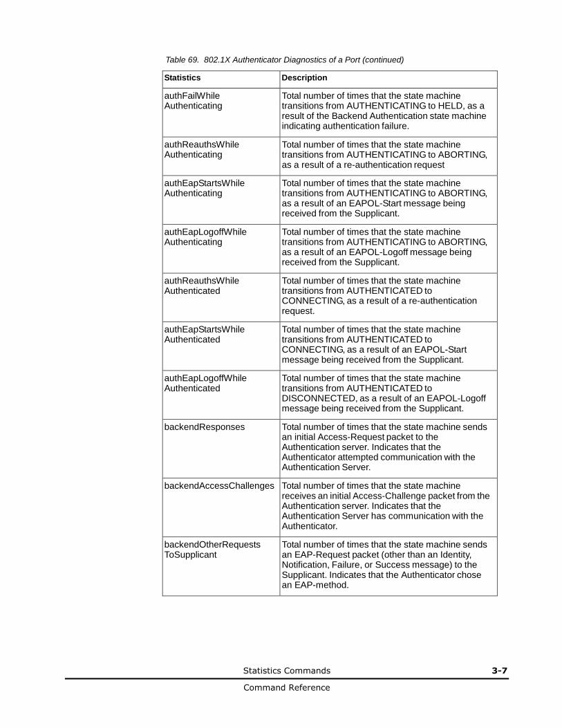
Statistics Commands 3-7
Command Reference
Table 69. 802.1X Authenticator Diagnostics of a Port (continued)
Statistics Description
authFailWhile Authenticating
Total number of times that the state machine transitions from AUTHENTICATING to HELD, as a result of the Backend Authentication state machine indicating authentication failure.
authReauthsWhile Authenticating
Total number of times that the state machine transitions from AUTHENTICATING to ABORTING, as a result of a re-authentication request
authEapStartsWhile Authenticating
Total number of times that the state machine transitions from AUTHENTICATING to ABORTING, as a result of an EAPOL-Start message being received from the Supplicant.
authEapLogoffWhile Authenticating
Total number of times that the state machine transitions from AUTHENTICATING to ABORTING, as a result of an EAPOL-Logoff message being received from the Supplicant.
authReauthsWhile Authenticated
Total number of times that the state machine transitions from AUTHENTICATED to CONNECTING, as a result of a re-authentication request.
authEapStartsWhile Authenticated
Total number of times that the state machine transitions from AUTHENTICATED to CONNECTING, as a result of an EAPOL-Start message being received from the Supplicant.
authEapLogoffWhile Authenticated
Total number of times that the state machine transitions from AUTHENTICATED to DISCONNECTED, as a result of an EAPOL-Logoff message being received from the Supplicant.
backendResponses Total number of times that the state machine sends an initial Access-Request packet to the Authentication server. Indicates that the Authenticator attempted communication with the Authentication Server.
backendAccessChallenges Total number of times that the state machine receives an initial Access-Challenge packet from the Authentication server. Indicates that the Authentication Server has communication with the Authenticator.
backendOtherRequests ToSupplicant
Total number of times that the state machine sends an EAP-Request packet (other than an Identity, Notification, Failure, or Success message) to the Supplicant. Indicates that the Authenticator chose an EAP-method.
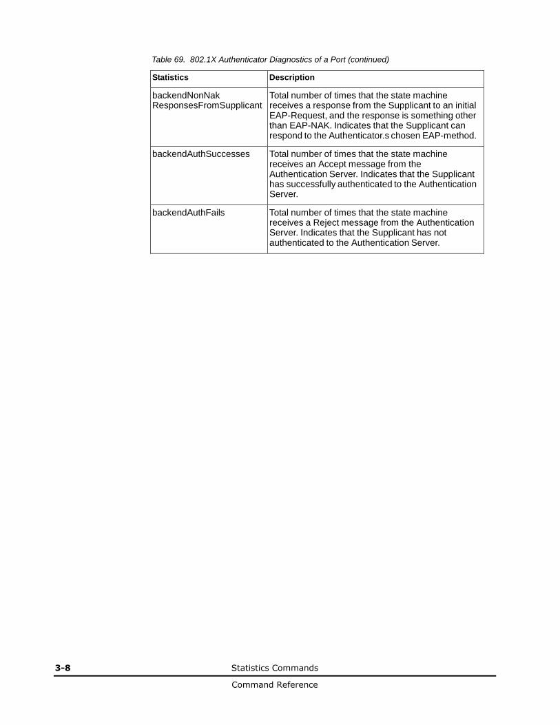
3-8 Statistics Commands
Command Reference
Table 69. 802.1X Authenticator Diagnostics of a Port (continued)
Statistics Description
backendNonNak ResponsesFromSupplicant
Total number of times that the state machine receives a response from the Supplicant to an initial EAP-Request, and the response is something other than EAP-NAK. Indicates that the Supplicant can respond to the Authenticator.s chosen EAP-method.
backendAuthSuccesses Total number of times that the state machine receives an Accept message from the Authentication Server. Indicates that the Supplicant has successfully authenticated to the Authentication Server.
backendAuthFails Total number of times that the state machine receives a Reject message from the Authentication Server. Indicates that the Supplicant has not authenticated to the Authentication Server.
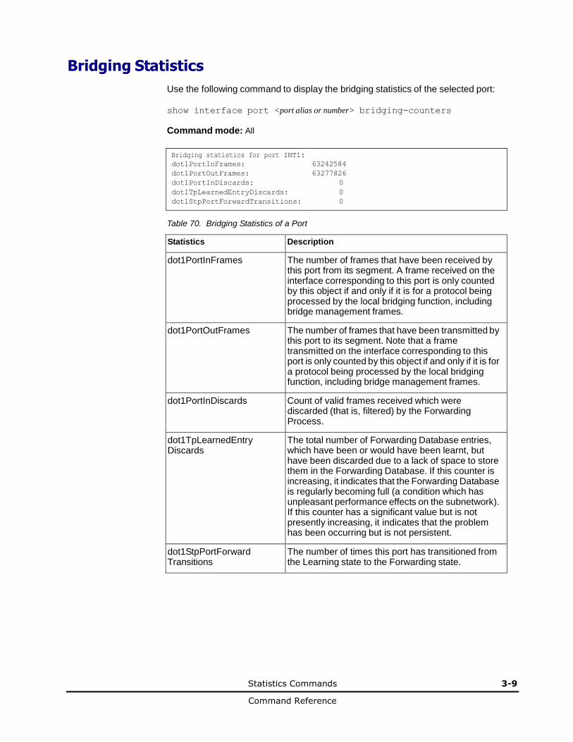
Statistics Commands 3-9
Command Reference
Bridging Statistics
Use the following command to display the bridging statistics of the selected port:
show interface port <port alias or number> bridging-counters
Command mode: All
Bridging statistics for port INT1: dot1PortInFrames: 63242584
dot1PortOutFrames: 63277826
dot1PortInDiscards: 0
dot1TpLearnedEntryDiscards: 0
dot1StpPortForwardTransitions: 0
Table 70. Bridging Statistics of a Port
Statistics Description
dot1PortInFrames The number of frames that have been received by this port from its segment. A frame received on the interface corresponding to this port is only counted by this object if and only if it is for a protocol being processed by the local bridging function, including bridge management frames.
dot1PortOutFrames The number of frames that have been transmitted by this port to its segment. Note that a frame transmitted on the interface corresponding to this port is only counted by this object if and only if it is for a protocol being processed by the local bridging function, including bridge management frames.
dot1PortInDiscards Count of valid frames received which were discarded (that is, filtered) by the Forwarding Process.
dot1TpLearnedEntry Discards
The total number of Forwarding Database entries, which have been or would have been learnt, but have been discarded due to a lack of space to store them in the Forwarding Database. If this counter is increasing, it indicates that the Forwarding Database is regularly becoming full (a condition which has unpleasant performance effects on the subnetwork). If this counter has a significant value but is not presently increasing, it indicates that the problem has been occurring but is not persistent.
dot1StpPortForward Transitions
The number of times this port has transitioned from the Learning state to the Forwarding state.
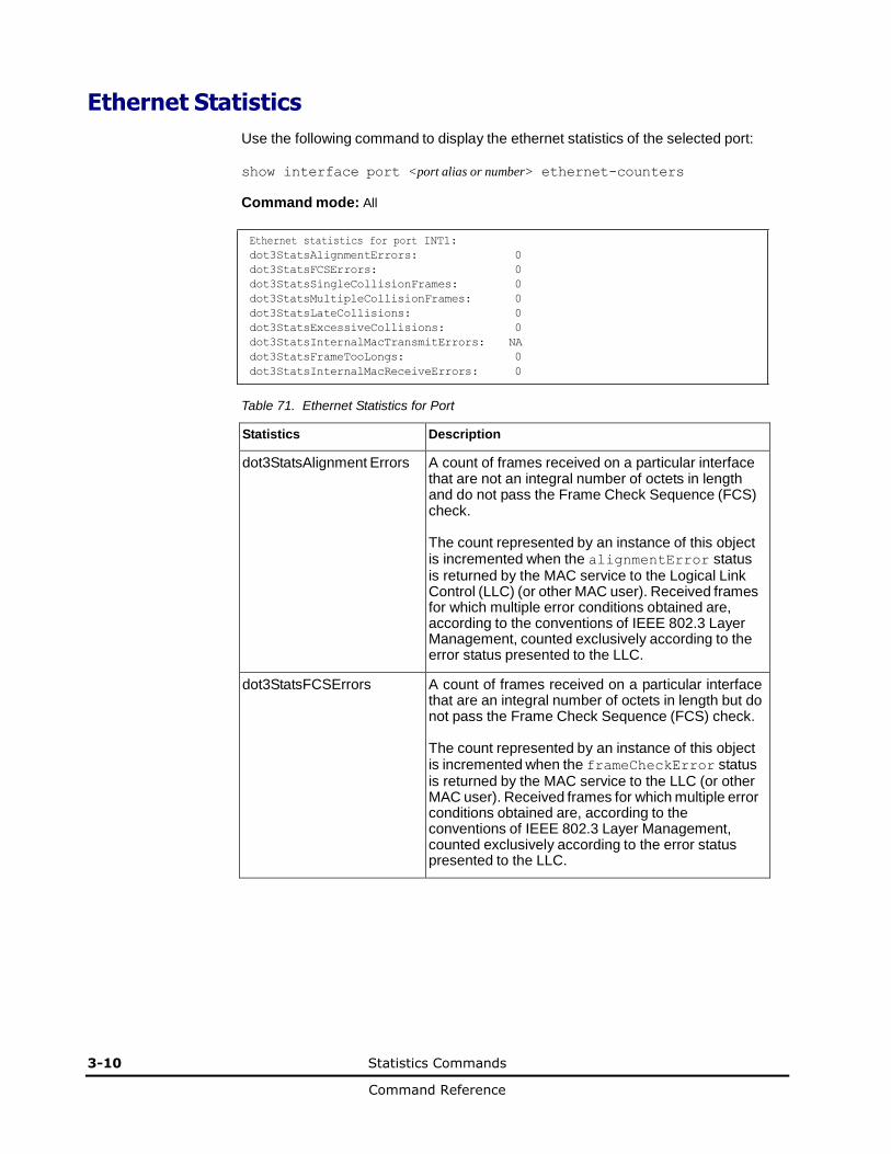
3-10 Statistics Commands
Command Reference
Ethernet Statistics
Use the following command to display the ethernet statistics of the selected port:
show interface port <port alias or number> ethernet-counters
Command mode: All
Ethernet statistics for port INT1:
dot3StatsAlignmentErrors: 0
dot3StatsFCSErrors: 0
dot3StatsSingleCollisionFrames: 0
dot3StatsMultipleCollisionFrames: 0
dot3StatsLateCollisions: 0
dot3StatsExcessiveCollisions: 0
dot3StatsInternalMacTransmitErrors: NA
dot3StatsFrameTooLongs: 0
dot3StatsInternalMacReceiveErrors: 0
Table 71. Ethernet Statistics for Port
Statistics Description
dot3StatsAlignment Errors A count of frames received on a particular interface that are not an integral number of octets in length and do not pass the Frame Check Sequence (FCS) check. The count represented by an instance of this object is incremented when the alignmentError status is returned by the MAC service to the Logical Link Control (LLC) (or other MAC user). Received frames for which multiple error conditions obtained are, according to the conventions of IEEE 802.3 Layer Management, counted exclusively according to the error status presented to the LLC.
dot3StatsFCSErrors A count of frames received on a particular interface that are an integral number of octets in length but do not pass the Frame Check Sequence (FCS) check. The count represented by an instance of this object is incremented when the frameCheckError status is returned by the MAC service to the LLC (or other MAC user). Received frames for which multiple error conditions obtained are, according to the conventions of IEEE 802.3 Layer Management, counted exclusively according to the error status presented to the LLC.
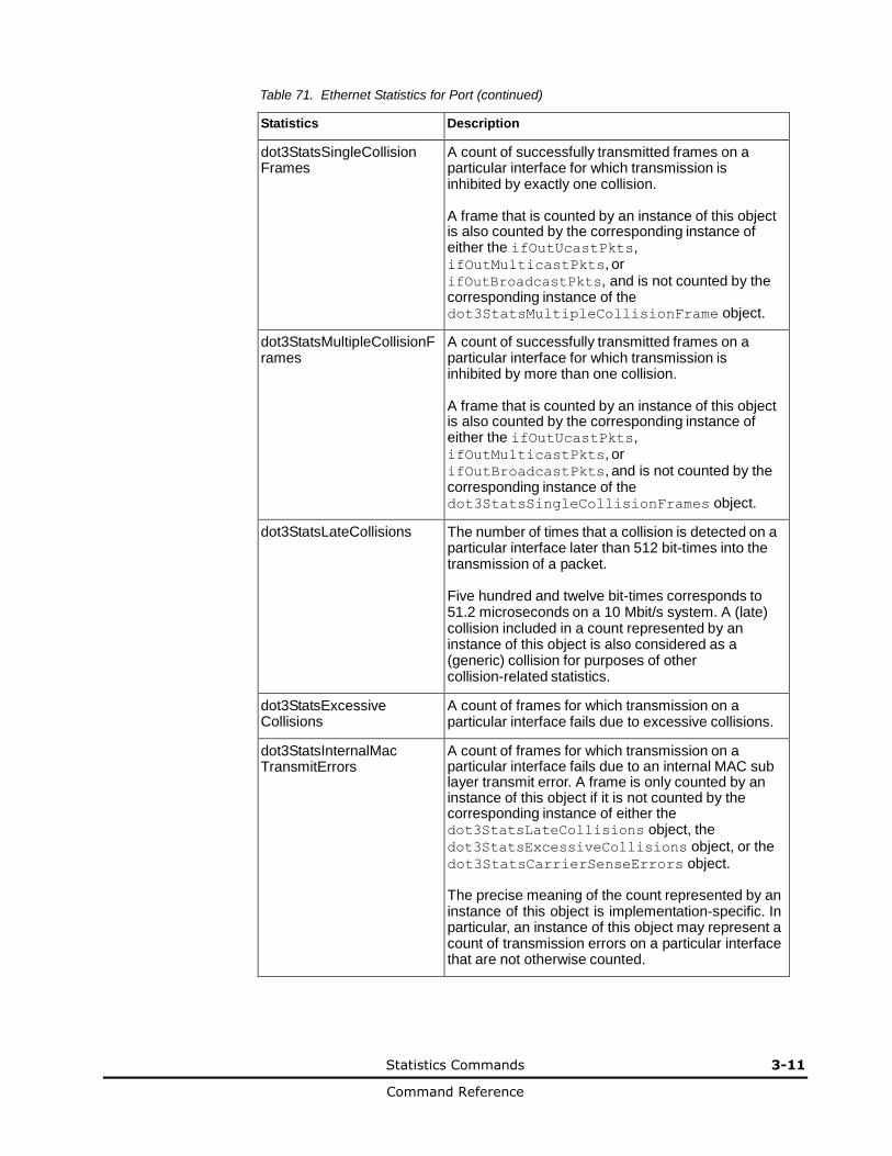
Statistics Commands 3-11
Command Reference
Table 71. Ethernet Statistics for Port (continued)
Statistics Description
dot3StatsSingleCollision Frames
A count of successfully transmitted frames on a particular interface for which transmission is inhibited by exactly one collision. A frame that is counted by an instance of this object is also counted by the corresponding instance of either the ifOutUcastPkts, ifOutMulticastPkts, or ifOutBroadcastPkts, and is not counted by the corresponding instance of the dot3StatsMultipleCollisionFrame object.
dot3StatsMultipleCollisionF rames
A count of successfully transmitted frames on a particular interface for which transmission is inhibited by more than one collision. A frame that is counted by an instance of this object is also counted by the corresponding instance of either the ifOutUcastPkts, ifOutMulticastPkts, or ifOutBroadcastPkts, and is not counted by the corresponding instance of the dot3StatsSingleCollisionFrames object.
dot3StatsLateCollisions The number of times that a collision is detected on a particular interface later than 512 bit-times into the transmission of a packet. Five hundred and twelve bit-times corresponds to 51.2 microseconds on a 10 Mbit/s system. A (late) collision included in a count represented by an instance of this object is also considered as a (generic) collision for purposes of other collision-related statistics.
dot3StatsExcessive Collisions
A count of frames for which transmission on a particular interface fails due to excessive collisions.
dot3StatsInternalMac TransmitErrors
A count of frames for which transmission on a particular interface fails due to an internal MAC sub layer transmit error. A frame is only counted by an instance of this object if it is not counted by the corresponding instance of either the dot3StatsLateCollisions object, the dot3StatsExcessiveCollisions object, or the dot3StatsCarrierSenseErrors object. The precise meaning of the count represented by an instance of this object is implementation-specific. In particular, an instance of this object may represent a count of transmission errors on a particular interface that are not otherwise counted.
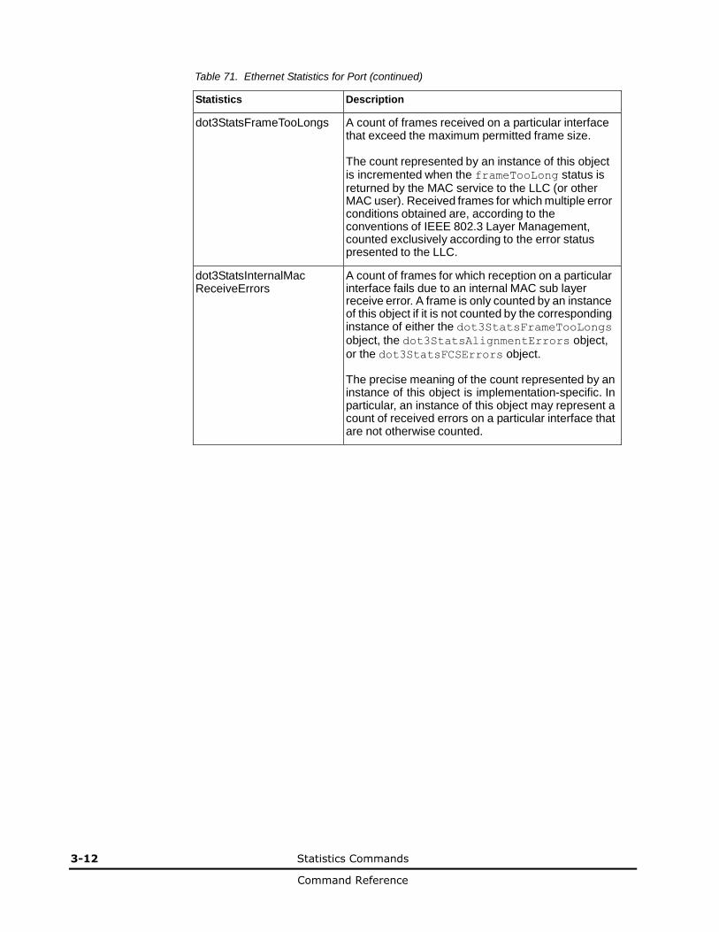
3-12 Statistics Commands
Command Reference
Table 71. Ethernet Statistics for Port (continued)
Statistics Description
dot3StatsFrameTooLongs A count of frames received on a particular interface that exceed the maximum permitted frame size. The count represented by an instance of this object is incremented when the frameTooLong status is returned by the MAC service to the LLC (or other MAC user). Received frames for which multiple error conditions obtained are, according to the conventions of IEEE 802.3 Layer Management, counted exclusively according to the error status presented to the LLC.
dot3StatsInternalMac ReceiveErrors
A count of frames for which reception on a particular interface fails due to an internal MAC sub layer receive error. A frame is only counted by an instance of this object if it is not counted by the corresponding instance of either the dot3StatsFrameTooLongs object, the dot3StatsAlignmentErrors object, or the dot3StatsFCSErrors object. The precise meaning of the count represented by an instance of this object is implementation-specific. In particular, an instance of this object may represent a count of received errors on a particular interface that are not otherwise counted.
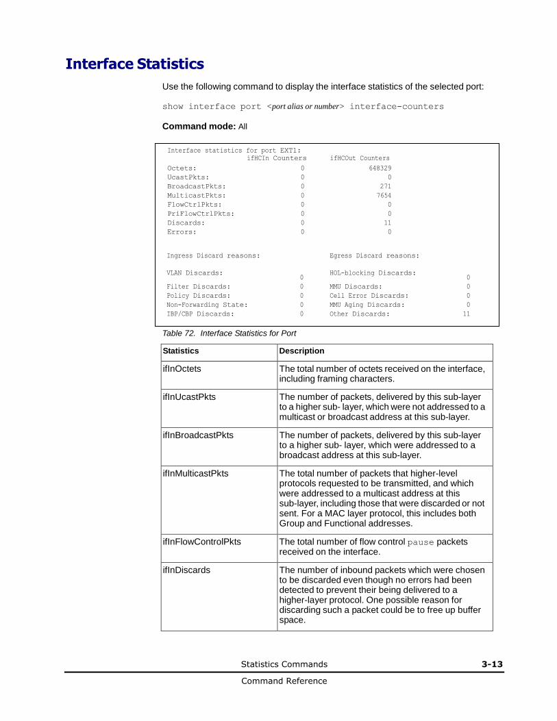
Statistics Commands 3-13
Command Reference
Interface Statistics
Use the following command to display the interface statistics of the selected port:
show interface port <port alias or number> interface-counters
Command mode: All
Interface statistics for port EXT1:
ifHCIn Counters ifHCOut Counters
Octets: 0 648329
UcastPkts: 0 0
BroadcastPkts: 0 271
MulticastPkts: 0 7654
FlowCtrlPkts: 0 0
PriFlowCtrlPkts: 0 0
Discards: 0 11
Errors: 0 0
Ingress Discard reasons:
VLAN Discards:
0
Egress Discard reasons:
HOL-blocking Discards:
0
Filter Discards: 0 MMU Discards: 0
Policy Discards: 0 Cell Error Discards: 0
Non-Forwarding State: 0 MMU Aging Discards: 0
IBP/CBP Discards: 0 Other Discards: 11
Table 72. Interface Statistics for Port
Statistics Description
ifInOctets The total number of octets received on the interface, including framing characters.
ifInUcastPkts The number of packets, delivered by this sub-layer to a higher sub- layer, which were not addressed to a multicast or broadcast address at this sub-layer.
ifInBroadcastPkts The number of packets, delivered by this sub-layer to a higher sub- layer, which were addressed to a broadcast address at this sub-layer.
ifInMulticastPkts The total number of packets that higher-level protocols requested to be transmitted, and which were addressed to a multicast address at this sub-layer, including those that were discarded or not sent. For a MAC layer protocol, this includes both Group and Functional addresses.
ifInFlowControlPkts The total number of flow control pause packets received on the interface.
ifInDiscards The number of inbound packets which were chosen to be discarded even though no errors had been detected to prevent their being delivered to a higher-layer protocol. One possible reason for discarding such a packet could be to free up buffer space.
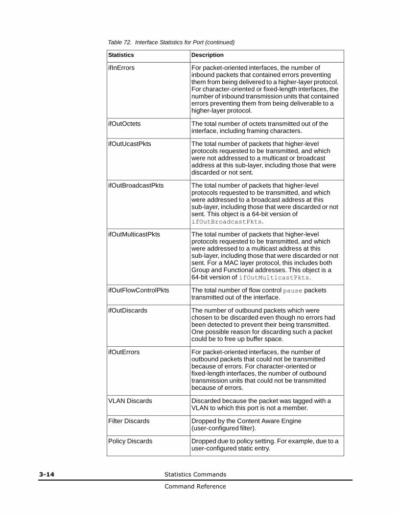
3-14 Statistics Commands
Command Reference
Table 72. Interface Statistics for Port (continued)
Statistics Description
ifInErrors For packet-oriented interfaces, the number of inbound packets that contained errors preventing them from being delivered to a higher-layer protocol. For character-oriented or fixed-length interfaces, the number of inbound transmission units that contained errors preventing them from being deliverable to a higher-layer protocol.
ifOutOctets The total number of octets transmitted out of the interface, including framing characters.
ifOutUcastPkts The total number of packets that higher-level protocols requested to be transmitted, and which were not addressed to a multicast or broadcast address at this sub-layer, including those that were discarded or not sent.
ifOutBroadcastPkts The total number of packets that higher-level protocols requested to be transmitted, and which were addressed to a broadcast address at this sub-layer, including those that were discarded or not sent. This object is a 64-bit version of ifOutBroadcastPkts.
ifOutMulticastPkts The total number of packets that higher-level protocols requested to be transmitted, and which were addressed to a multicast address at this sub-layer, including those that were discarded or not sent. For a MAC layer protocol, this includes both Group and Functional addresses. This object is a 64-bit version of ifOutMulticastPkts.
ifOutFlowControlPkts The total number of flow control pause packets transmitted out of the interface.
ifOutDiscards The number of outbound packets which were chosen to be discarded even though no errors had been detected to prevent their being transmitted. One possible reason for discarding such a packet could be to free up buffer space.
ifOutErrors For packet-oriented interfaces, the number of outbound packets that could not be transmitted because of errors. For character-oriented or fixed-length interfaces, the number of outbound transmission units that could not be transmitted because of errors.
VLAN Discards Discarded because the packet was tagged with a VLAN to which this port is not a member.
Filter Discards Dropped by the Content Aware Engine (user-configured filter).
Policy Discards Dropped due to policy setting. For example, due to a user-configured static entry.
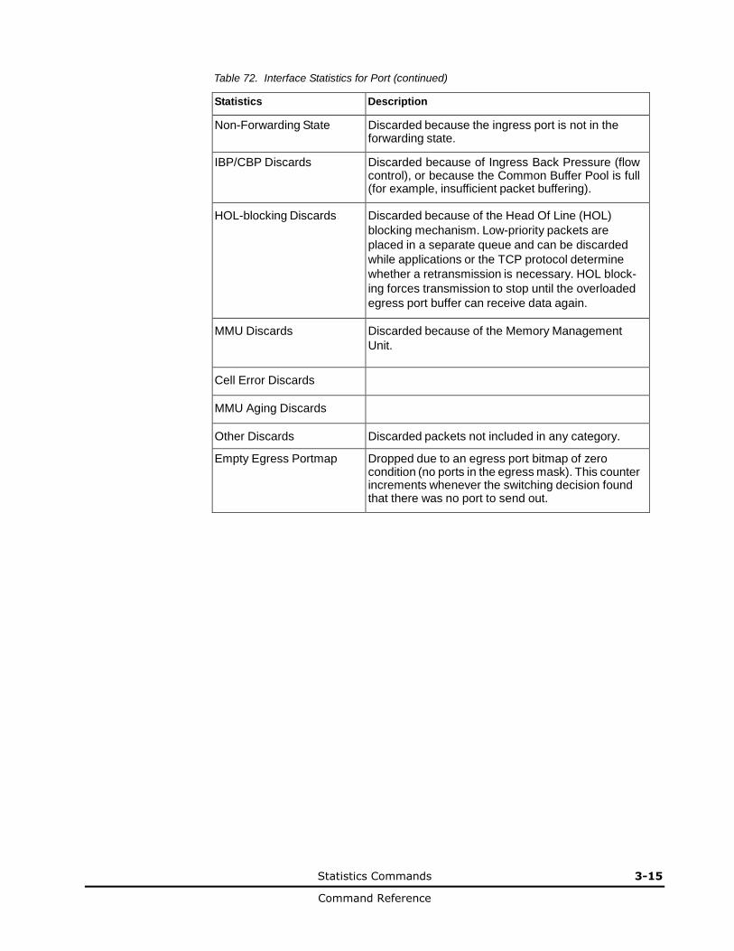
Statistics Commands 3-15
Command Reference
Table 72. Interface Statistics for Port (continued)
Statistics Description
Non-Forwarding State Discarded because the ingress port is not in the forwarding state.
IBP/CBP Discards Discarded because of Ingress Back Pressure (flow control), or because the Common Buffer Pool is full (for example, insufficient packet buffering).
HOL-blocking Discards Discarded because of the Head Of Line (HOL)
blocking mechanism. Low-priority packets are
placed in a separate queue and can be discarded
while applications or the TCP protocol determine
whether a retransmission is necessary. HOL block-
ing forces transmission to stop until the overloaded
egress port buffer can receive data again.
MMU Discards Discarded because of the Memory Management
Unit.
Cell Error Discards
MMU Aging Discards
Other Discards Discarded packets not included in any category.
Empty Egress Portmap Dropped due to an egress port bitmap of zero condition (no ports in the egress mask). This counter increments whenever the switching decision found that there was no port to send out.
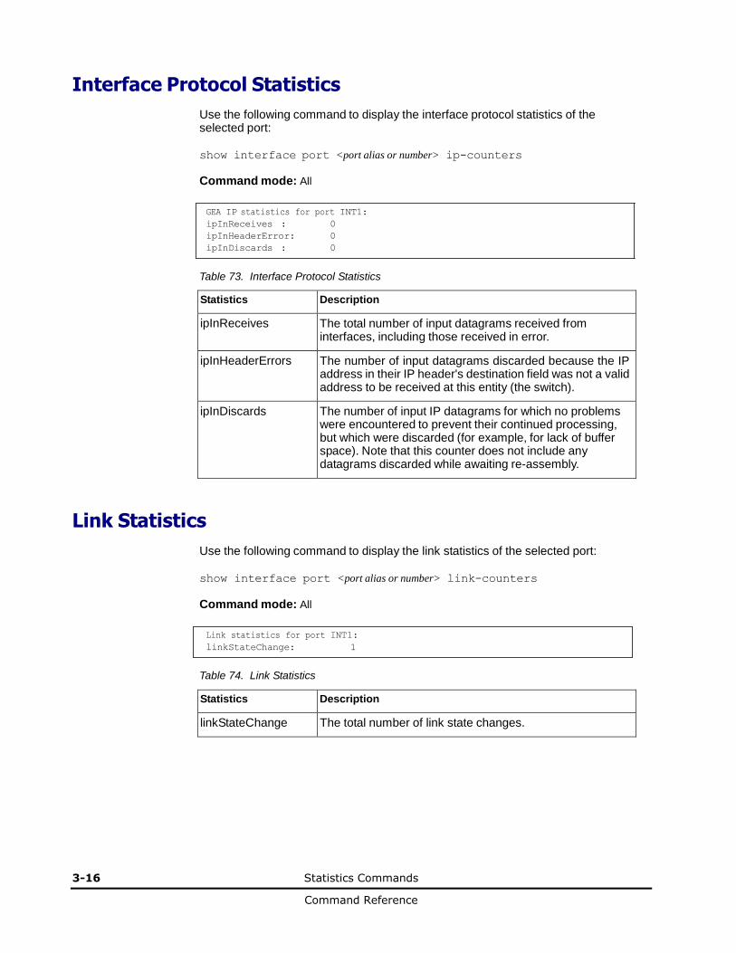
3-16 Statistics Commands
Command Reference
Interface Protocol Statistics
Use the following command to display the interface protocol statistics of the selected port:
show interface port <port alias or number> ip-counters
Command mode: All
GEA IP statistics for port INT1:
ipInReceives : 0
ipInHeaderError: 0
ipInDiscards : 0
Table 73. Interface Protocol Statistics
Statistics Description
ipInReceives The total number of input datagrams received from interfaces, including those received in error.
ipInHeaderErrors The number of input datagrams discarded because the IP address in their IP header's destination field was not a valid address to be received at this entity (the switch).
ipInDiscards The number of input IP datagrams for which no problems were encountered to prevent their continued processing, but which were discarded (for example, for lack of buffer space). Note that this counter does not include any datagrams discarded while awaiting re-assembly.
Link Statistics
Use the following command to display the link statistics of the selected port:
show interface port <port alias or number> link-counters
Command mode: All
Link statistics for port INT1:
linkStateChange: 1
Table 74. Link Statistics
Statistics Description
linkStateChange The total number of link state changes.
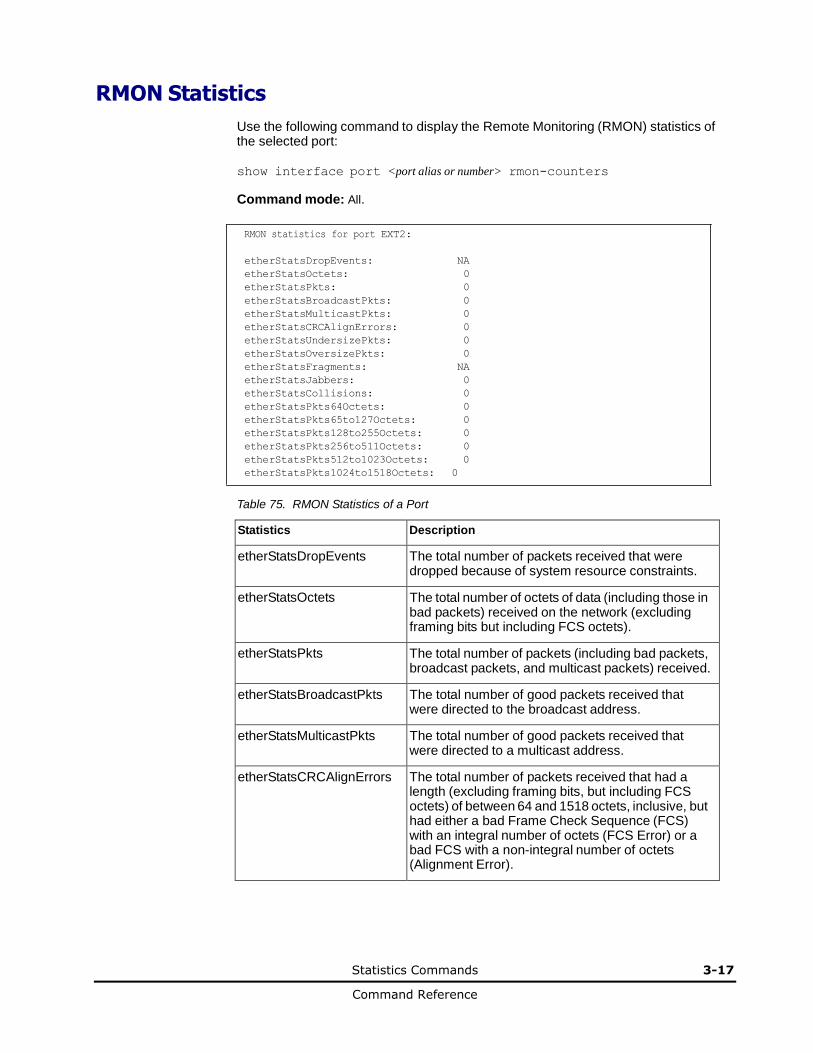
Statistics Commands 3-17
Command Reference
RMON Statistics
Use the following command to display the Remote Monitoring (RMON) statistics of the selected port:
show interface port <port alias or number> rmon-counters
Command mode: All.
RMON statistics for port EXT2:
etherStatsDropEvents: NA
etherStatsOctets: 0
etherStatsPkts: 0
etherStatsBroadcastPkts: 0
etherStatsMulticastPkts: 0
etherStatsCRCAlignErrors: 0
etherStatsUndersizePkts: 0
etherStatsOversizePkts: 0
etherStatsFragments: NA
etherStatsJabbers: 0
etherStatsCollisions: 0
etherStatsPkts64Octets: 0
etherStatsPkts65to127Octets: 0
etherStatsPkts128to255Octets: 0
etherStatsPkts256to511Octets: 0
etherStatsPkts512to1023Octets: 0
etherStatsPkts1024to1518Octets: 0
Table 75. RMON Statistics of a Port
Statistics Description
etherStatsDropEvents The total number of packets received that were dropped because of system resource constraints.
etherStatsOctets The total number of octets of data (including those in bad packets) received on the network (excluding framing bits but including FCS octets).
etherStatsPkts The total number of packets (including bad packets, broadcast packets, and multicast packets) received.
etherStatsBroadcastPkts The total number of good packets received that were directed to the broadcast address.
etherStatsMulticastPkts The total number of good packets received that were directed to a multicast address.
etherStatsCRCAlignErrors The total number of packets received that had a length (excluding framing bits, but including FCS octets) of between 64 and 1518 octets, inclusive, but had either a bad Frame Check Sequence (FCS) with an integral number of octets (FCS Error) or a bad FCS with a non-integral number of octets (Alignment Error).
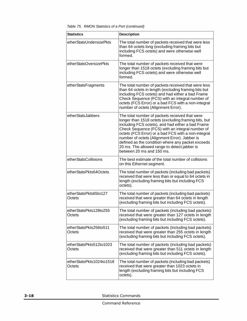
3-18 Statistics Commands
Command Reference
Table 75. RMON Statistics of a Port (continued)
Statistics Description
etherStatsUndersizePkts The total number of packets received that were less than 64 octets long (excluding framing bits but including FCS octets) and were otherwise well formed.
etherStatsOversizePkts The total number of packets received that were longer than 1518 octets (excluding framing bits but including FCS octets) and were otherwise well formed.
etherStatsFragments The total number of packets received that were less than 64 octets in length (excluding framing bits but including FCS octets) and had either a bad Frame Check Sequence (FCS) with an integral number of octets (FCS Error) or a bad FCS with a non-integral number of octets (Alignment Error).
etherStatsJabbers The total number of packets received that were longer than 1518 octets (excluding framing bits, but including FCS octets), and had either a bad Frame Check Sequence (FCS) with an integral number of octets (FCS Error) or a bad FCS with a non-integral number of octets (Alignment Error). Jabber is defined as the condition where any packet exceeds 20 ms. The allowed range to detect jabber is between 20 ms and 150 ms.
etherStatsCollisions The best estimate of the total number of collisions on this Ethernet segment.
etherStatsPkts64Octets The total number of packets (including bad packets) received that were less than or equal to 64 octets in length (excluding framing bits but including FCS octets).
etherStatsPkts65to127 Octets
The total number of packets (including bad packets) received that were greater than 64 octets in length (excluding framing bits but including FCS octets).
etherStatsPkts128to255 Octets
The total number of packets (including bad packets) received that were greater than 127 octets in length (excluding framing bits but including FCS octets).
etherStatsPkts256to511 Octets
The total number of packets (including bad packets) received that were greater than 255 octets in length (excluding framing bits but including FCS octets).
etherStatsPkts512to1023 Octets
The total number of packets (including bad packets) received that were greater than 511 octets in length (excluding framing bits but including FCS octets).
etherStatsPkts1024to1518 Octets
The total number of packets (including bad packets) received that were greater than 1023 octets in length (excluding framing bits but including FCS octets).
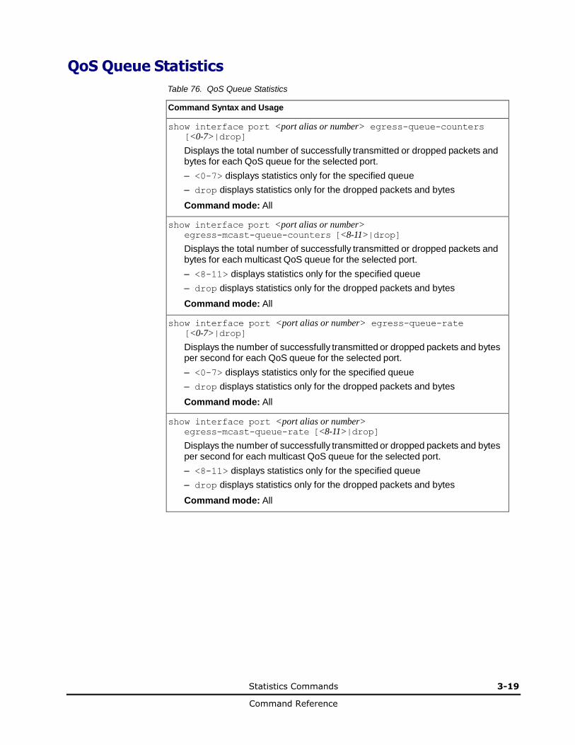
Statistics Commands 3-19
Command Reference
QoS Queue Statistics
Table 76. QoS Queue Statistics
Command Syntax and Usage
show interface port <port alias or number> egress-queue-counters [<0-7>|drop]
Displays the total number of successfully transmitted or dropped packets and bytes for each QoS queue for the selected port.
– <0-7> displays statistics only for the specified queue
– drop displays statistics only for the dropped packets and bytes
Command mode: All
show interface port <port alias or number> egress-mcast-queue-counters [<8-11>|drop]
Displays the total number of successfully transmitted or dropped packets and bytes for each multicast QoS queue for the selected port.
– <8-11> displays statistics only for the specified queue
– drop displays statistics only for the dropped packets and bytes
Command mode: All
show interface port <port alias or number> egress-queue-rate [<0-7>|drop]
Displays the number of successfully transmitted or dropped packets and bytes per second for each QoS queue for the selected port.
– <0-7> displays statistics only for the specified queue
– drop displays statistics only for the dropped packets and bytes
Command mode: All
show interface port <port alias or number> egress-mcast-queue-rate [<8-11>|drop]
Displays the number of successfully transmitted or dropped packets and bytes per second for each multicast QoS queue for the selected port.
– <8-11> displays statistics only for the specified queue
– drop displays statistics only for the dropped packets and bytes
Command mode: All
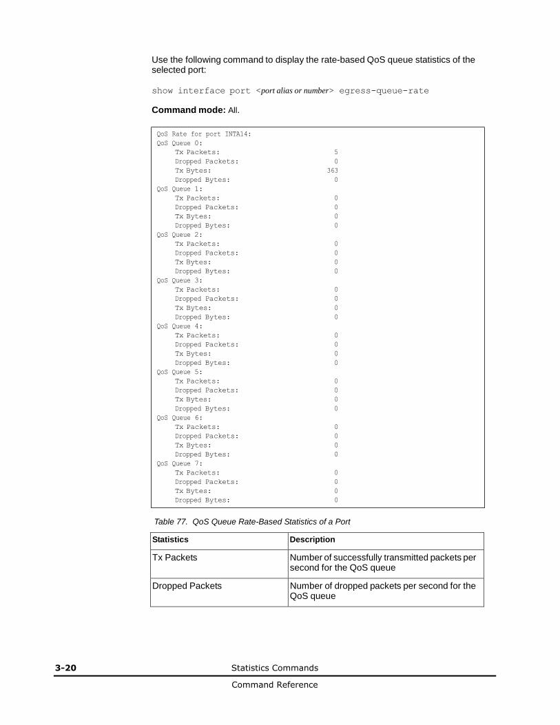
3-20 Statistics Commands
Command Reference
Use the following command to display the rate-based QoS queue statistics of the selected port:
show interface port <port alias or number> egress-queue-rate
Command mode: All.
QoS Rate for port INTA14:
QoS Queue 0:
Tx Packets: 5
Dropped Packets: 0
Tx Bytes: 363
Dropped Bytes: 0
QoS Queue 1:
Tx Packets: 0
Dropped Packets: 0
Tx Bytes: 0
Dropped Bytes: 0
QoS Queue 2:
Tx Packets: 0
Dropped Packets: 0
Tx Bytes: 0
Dropped Bytes: 0
QoS Queue 3:
Tx Packets: 0
Dropped Packets: 0
Tx Bytes: 0
Dropped Bytes: 0
QoS Queue 4:
Tx Packets: 0
Dropped Packets: 0
Tx Bytes: 0
Dropped Bytes: 0
QoS Queue 5:
Tx Packets: 0
Dropped Packets: 0
Tx Bytes: 0
Dropped Bytes: 0
QoS Queue 6:
Tx Packets: 0
Dropped Packets: 0
Tx Bytes: 0
Dropped Bytes: 0
QoS Queue 7:
Tx Packets: 0
Dropped Packets: 0
Tx Bytes: 0
Dropped Bytes: 0
Table 77. QoS Queue Rate-Based Statistics of a Port
Statistics Description
Tx Packets Number of successfully transmitted packets per second for the QoS queue
Dropped Packets Number of dropped packets per second for the QoS queue

Statistics Commands 3-21
Command Reference
Table 77. QoS Queue Rate-Based Statistics of a Port (continued)
Statistics Description
Tx Bytes Number of successfully transmitted bytes per second for the QoS queue
Dropped Bytes Number of dropped bytes per second for the QoS queue
Use the following command to display the -based QoS queue statistics of the selected port:
show interface port <port alias or number> egress-queue-counters
Command mode: All. QoS Rate for port 1:1:
QoS Queue 0:
Tx Packets: 0
Dropped Packets: 0
Tx Bytes: 0
Dropped Bytes: 0
QoS Queue 1:
Tx Packets: 0
Dropped Packets: 0
Tx Bytes: 0
Dropped Bytes: 0
QoS Queue 2:
Tx Packets: 0
Dropped Packets: 0
Tx Bytes: 0
Dropped Bytes: 0
QoS Queue 3:
Tx Packets: 0
Dropped Packets: 0
Tx Bytes: 0
Dropped Bytes: 0
QoS Queue 4:
Tx Packets: 0
Dropped Packets: 0
Tx Bytes: 0
Dropped Bytes: 0
QoS Queue 5:
Tx Packets: 0
Dropped Packets: 0
Tx Bytes: 0
Dropped Bytes: 0
QoS Queue 6:
Tx Packets: 0
Dropped Packets: 0
Tx Bytes: 0
Dropped Bytes: 0
QoS Queue 7:
Tx Packets: 0
Dropped Packets: 0
Tx Bytes: 0
Dropped Bytes: 0
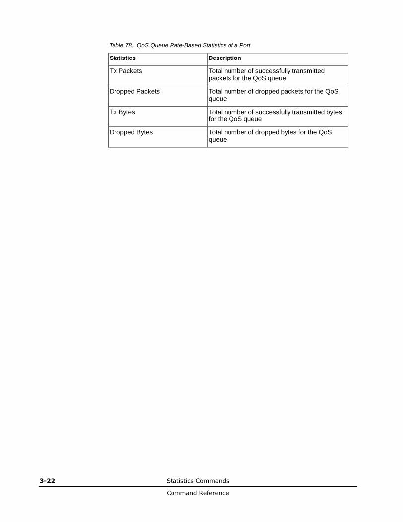
3-22 Statistics Commands
Command Reference
Table 78. QoS Queue Rate-Based Statistics of a Port
Statistics Description
Tx Packets Total number of successfully transmitted packets for the QoS queue
Dropped Packets Total number of dropped packets for the QoS queue
Tx Bytes Total number of successfully transmitted bytes for the QoS queue
Dropped Bytes Total number of dropped bytes for the QoS queue

Statistics Commands 3-23
Command Reference
Trunk Group Statistics
Table 79. Trunk Group Statistics Commands
Command Syntax and Usage
show interface portchannel <trunk group number> interface-counters
Displays interface statistics for the trunk group.
Command mode: All
clear interface portchannel <trunk group number> counters
Clears all the statistics on the specified trunk group.
Command mode: All except User EXEC

3-24 Statistics Commands
Command Reference
Layer 2 Statistics
Table 80. Layer 2 Statistics Commands
Command Syntax and Usage
show interface port <port alias or number> lacp counters
Displays Link Aggregation Control Protocol (LACP) statistics. See page 3-25 for sample output.
Command mode: All
clear interface port <port alias or number> lacp counters
Clears Link Aggregation Control Protocol (LACP) statistics.
Command mode: All except User EXEC
show hotlinks counters
Displays Hot Links statistics. See page 3-26 for sample output.
Command mode: All except User EXEC
clear hotlinks
Clears all Hot Links statistics.
Command mode: All except User EXEC
show interface port <port alias or number> lldp counters
Displays LLDP statistics. See page 3-28 for sample output.
Command mode: All except User EXEC
show oam counters
Displays OAM statistics. See page 3-29 for sample output.
Command mode: All except User EXEC
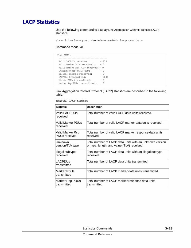
Statistics Commands 3-25
Command Reference
LACP Statistics
Use the following command to display Link Aggregation Control Protocol (LACP)
statistics:
show interface port <port alias or number> lacp counters
Command mode: All
Port EXT1:
--------------------------------------
Valid LACPDUs received: - 870
Valid Marker PDUs received: - 0
Valid Marker Rsp PDUs received: - 0
Unknown version/TLV type: - 0
Illegal subtype received: - 0
LACPDUs transmitted: - 6031
Marker PDUs transmitted: - 0
Marker Rsp PDUs transmitted: - 0
Link Aggregation Control Protocol (LACP) statistics are described in the following table:
Table 81. LACP Statistics
Statistic Description
Valid LACPDUs received
Total number of valid LACP data units received.
Valid Marker PDUs received
Total number of valid LACP marker data units received.
Valid Marker Rsp PDUs received
Total number of valid LACP marker response data units received.
Unknown version/TLV type
Total number of LACP data units with an unknown version or type, length, and value (TLV) received.
Illegal subtype received
Total number of LACP data units with an illegal subtype received.
LACPDUs transmitted
Total number of LACP data units transmitted.
Marker PDUs transmitted
Total number of LACP marker data units transmitted.
Marker Rsp PDUs transmitted
Total number of LACP marker response data units transmitted.

3-26 Statistics Commands
Command Reference
Hotlinks Statistics
Use the following command to display Hot Links statistics:
show hotlinks counters
Command mode: All
Hot Links Trigger Stats:
Trigger 1 statistics:
Trigger Name: Trigger 1
Master active: 0
Backup active: 0 FDB update: 0 failed: 0
The following table describes the Hotlinks statistics:
Table 82. Hotlinks Statistics
Statistic Description
Master active Total number of times the Master interface transitioned to the Active state.
Backup active Total number of times the Backup interface transitioned to the Active state.
FDB update Total number of FDB update requests sent.
failed Total number of FDB update requests that failed.

Statistics Commands 3-27
Command Reference
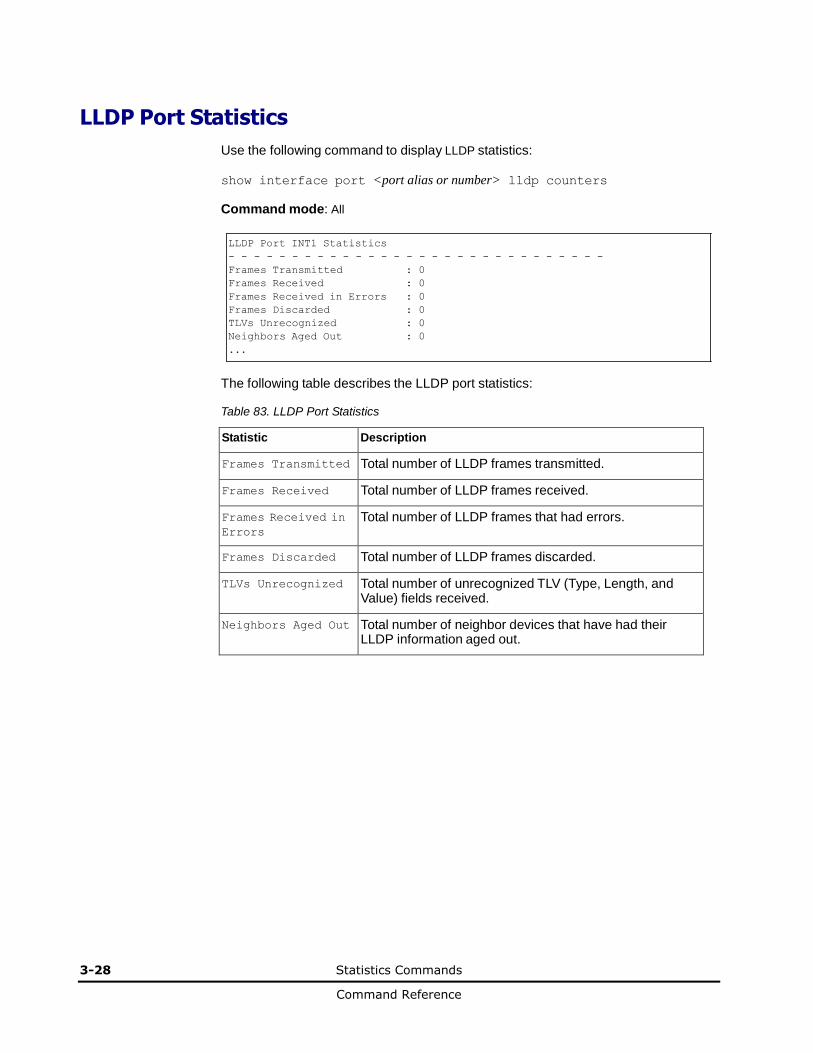
3-28 Statistics Commands
Command Reference
LLDP Port Statistics
Use the following command to display LLDP statistics:
show interface port <port alias or number> lldp counters
Command mode: All
LLDP Port INT1 Statistics
- - - - - - - - - - - - - - - - - - - - - - - - - - - - - -
Frames Transmitted : 0
Frames Received : 0
Frames Received in Errors : 0
Frames Discarded : 0
TLVs Unrecognized : 0
Neighbors Aged Out : 0
...
The following table describes the LLDP port statistics:
Table 83. LLDP Port Statistics
Statistic Description
Frames Transmitted Total number of LLDP frames transmitted.
Frames Received Total number of LLDP frames received.
Frames Received in
Errors
Total number of LLDP frames that had errors.
Frames Discarded Total number of LLDP frames discarded.
TLVs Unrecognized Total number of unrecognized TLV (Type, Length, and Value) fields received.
Neighbors Aged Out Total number of neighbor devices that have had their LLDP information aged out.
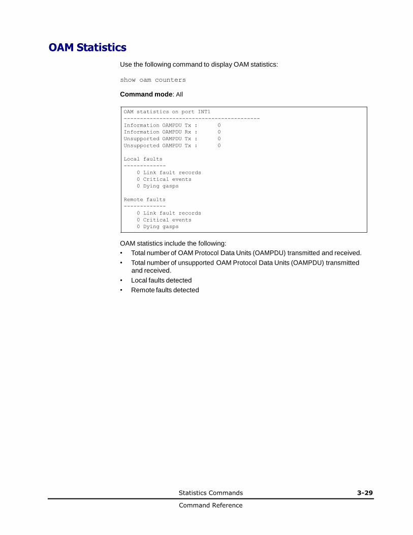
Statistics Commands 3-29
Command Reference
OAM Statistics
Use the following command to display OAM statistics:
show oam counters
Command mode: All
OAM statistics on port INT1
------------------------------------------
Information OAMPDU Tx : 0
Information OAMPDU Rx : 0
Unsupported OAMPDU Tx : 0
Unsupported OAMPDU Tx : 0
Local faults
-------------
0 Link fault records
0 Critical events
0 Dying gasps
Remote faults
-------------
0 Link fault records
0 Critical events
0 Dying gasps
OAM statistics include the following:
• Total number of OAM Protocol Data Units (OAMPDU) transmitted and received.
• Total number of unsupported OAM Protocol Data Units (OAMPDU) transmitted and received.
• Local faults detected
• Remote faults detected
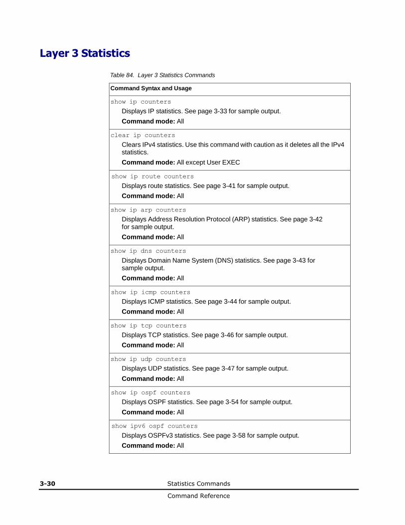
3-30 Statistics Commands
Command Reference
Layer 3 Statistics
Table 84. Layer 3 Statistics Commands
Command Syntax and Usage
show ip counters
Displays IP statistics. See page 3-33 for sample output.
Command mode: All
clear ip counters
Clears IPv4 statistics. Use this command with caution as it deletes all the IPv4 statistics.
Command mode: All except User EXEC
show ip route counters
Displays route statistics. See page 3-41 for sample output.
Command mode: All
show ip arp counters
Displays Address Resolution Protocol (ARP) statistics. See page 3-42 for sample output.
Command mode: All
show ip dns counters
Displays Domain Name System (DNS) statistics. See page 3-43 for sample output.
Command mode: All
show ip icmp counters
Displays ICMP statistics. See page 3-44 for sample output.
Command mode: All
show ip tcp counters
Displays TCP statistics. See page 3-46 for sample output.
Command mode: All
show ip udp counters
Displays UDP statistics. See page 3-47 for sample output.
Command mode: All
show ip ospf counters
Displays OSPF statistics. See page 3-54 for sample output.
Command mode: All
show ipv6 ospf counters
Displays OSPFv3 statistics. See page 3-58 for sample output.
Command mode: All
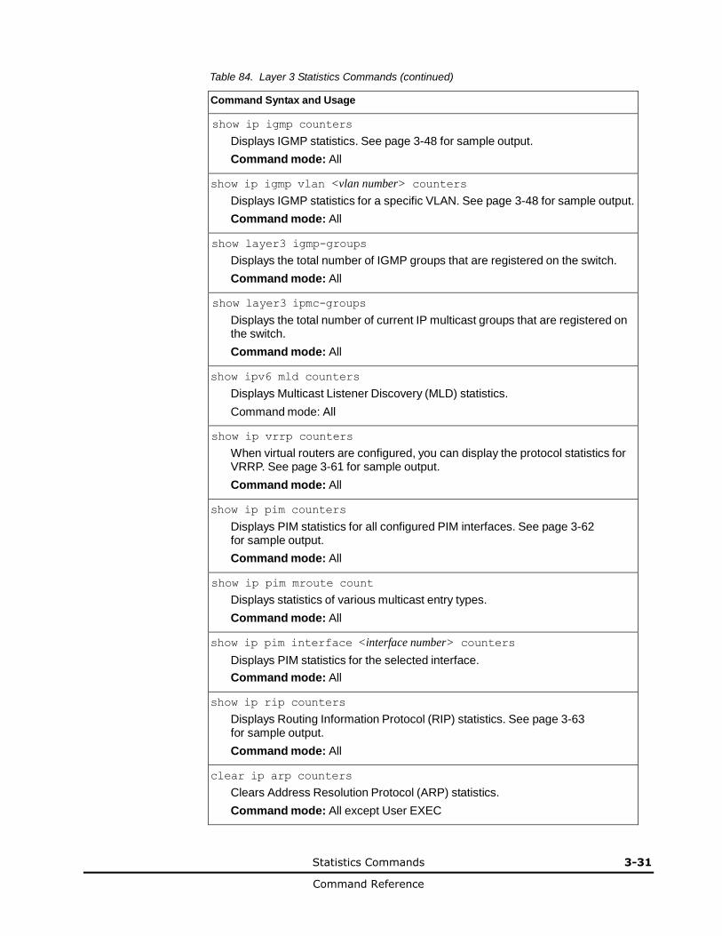
Statistics Commands 3-31
Command Reference
Table 84. Layer 3 Statistics Commands (continued)
Command Syntax and Usage
show ip igmp counters
Displays IGMP statistics. See page 3-48 for sample output.
Command mode: All
show ip igmp vlan <vlan number> counters
Displays IGMP statistics for a specific VLAN. See page 3-48 for sample output.
Command mode: All
show layer3 igmp-groups
Displays the total number of IGMP groups that are registered on the switch.
Command mode: All
show layer3 ipmc-groups
Displays the total number of current IP multicast groups that are registered on the switch.
Command mode: All
show ipv6 mld counters
Displays Multicast Listener Discovery (MLD) statistics.
Command mode: All
show ip vrrp counters
When virtual routers are configured, you can display the protocol statistics for VRRP. See page 3-61 for sample output.
Command mode: All
show ip pim counters
Displays PIM statistics for all configured PIM interfaces. See page 3-62 for sample output.
Command mode: All
show ip pim mroute count
Displays statistics of various multicast entry types.
Command mode: All
show ip pim interface <interface number> counters
Displays PIM statistics for the selected interface.
Command mode: All
show ip rip counters
Displays Routing Information Protocol (RIP) statistics. See page 3-63 for sample output.
Command mode: All
clear ip arp counters
Clears Address Resolution Protocol (ARP) statistics.
Command mode: All except User EXEC

3-32 Statistics Commands
Command Reference
Table 84. Layer 3 Statistics Commands (continued)
Command Syntax and Usage
clear ip dns counters
Clears Domain Name System (DNS) statistics.
Command mode: All except User EXEC
clear ip icmp counters
Clears Internet Control Message Protocol (ICMP) statistics.
Command mode: All except User EXEC
clear ip tcp counters
Clears Transmission Control Protocol (TCP) statistics.
Command mode: All except User EXEC
clear ip udp counters
Clears User Datagram Protocol (UDP) statistics.
Command mode: All except User EXEC
clear ip igmp [<VLAN number>] counters
Clears IGMP statistics for all VLANs or for a specific VLAN.
Command mode: All
clear ip vrrp counters
Clears VRRP statistics.
Command mode: All
clear ip counters
Clears IP statistics. Use this command with caution as it will delete all the IP statistics.
Command mode: All
clear ip rip counters
Clears Routing Information Protocol (RIP) statistics.
Command mode: All except User EXEC
clear ip ospf counters
Clears Open Shortest Path First (OSPF) statistics.
Command mode: All except User EXEC
show layer3 counters
Dumps all Layer 3 statistics. Use this command to gather data for tuning and debugging switch performance. If you want to capture dump data to a file, set your communication software on your workstation to capture session data prior to issuing the dump command.
Command mode: All
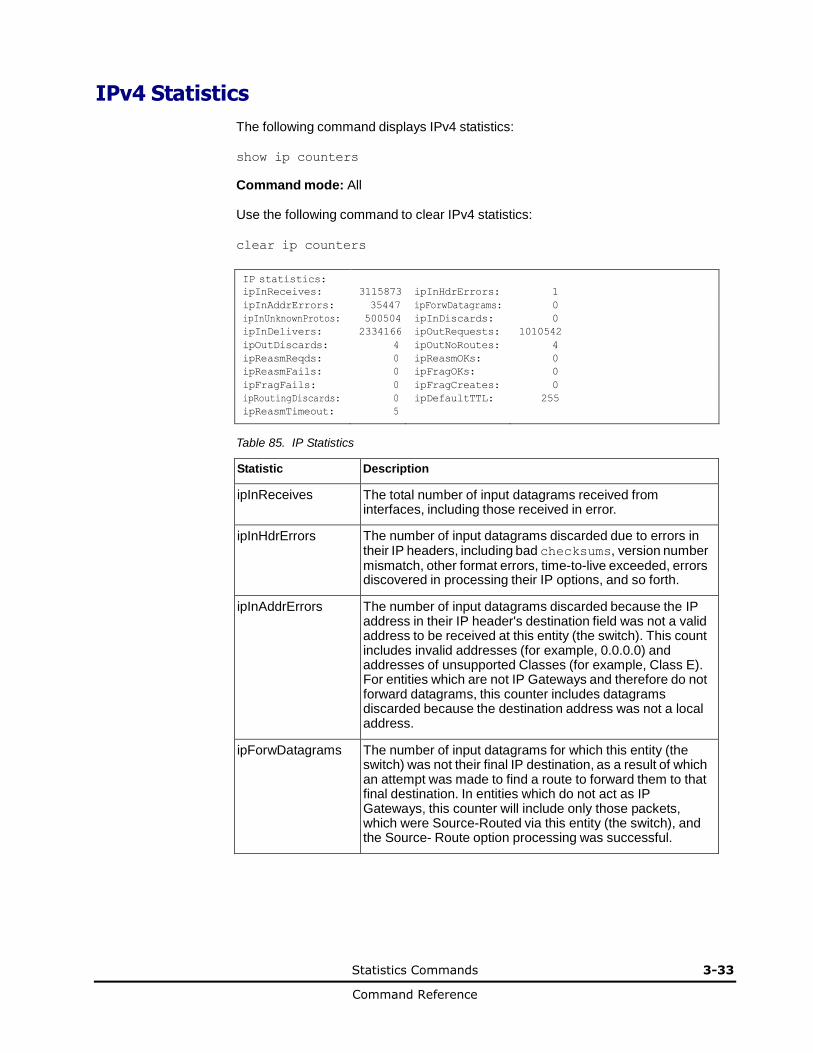
Statistics Commands 3-33
Command Reference
IPv4 Statistics
The following command displays IPv4 statistics:
show ip counters
Command mode: All
Use the following command to clear IPv4 statistics:
clear ip counters
IP statistics: ipInReceives: 3115873 ipInHdrErrors: 1
ipInAddrErrors: 35447 ipForwDatagrams: 0
ipInUnknownProtos: 500504 ipInDiscards: 0
ipInDelivers: 2334166 ipOutRequests: 1010542
ipOutDiscards: 4 ipOutNoRoutes: 4
ipReasmReqds: 0 ipReasmOKs: 0
ipReasmFails: 0 ipFragOKs: 0
ipFragFails: 0 ipFragCreates: 0
ipRoutingDiscards: 0 ipDefaultTTL: 255
ipReasmTimeout: 5
Table 85. IP Statistics
Statistic Description
ipInReceives The total number of input datagrams received from interfaces, including those received in error.
ipInHdrErrors The number of input datagrams discarded due to errors in their IP headers, including bad checksums, version number mismatch, other format errors, time-to-live exceeded, errors discovered in processing their IP options, and so forth.
ipInAddrErrors The number of input datagrams discarded because the IP address in their IP header's destination field was not a valid address to be received at this entity (the switch). This count includes invalid addresses (for example, 0.0.0.0) and addresses of unsupported Classes (for example, Class E). For entities which are not IP Gateways and therefore do not forward datagrams, this counter includes datagrams discarded because the destination address was not a local address.
ipForwDatagrams The number of input datagrams for which this entity (the switch) was not their final IP destination, as a result of which an attempt was made to find a route to forward them to that final destination. In entities which do not act as IP Gateways, this counter will include only those packets, which were Source-Routed via this entity (the switch), and the Source- Route option processing was successful.

3-34 Statistics Commands
Command Reference
Table 85. IP Statistics (continued)
Statistic Description
ipInUnknownProtos The number of locally addressed datagrams received successfully but discarded because of an unknown or unsupported protocol.
ipInDiscards The number of input IP datagrams for which no problems were encountered to prevent their continued processing, but which were discarded (for example, for lack of buffer space). Note that this counter does not include any datagrams discarded while awaiting re-assembly.
ipInDelivers The total number of input datagrams successfully delivered to IP user-protocols (including ICMP).
ipOutRequests The total number of IP datagrams which local IP user-protocols (including ICMP) supplied to IP in requests for transmission. Note that this counter does not include any datagrams counted in ipForwDatagrams.
ipOutDiscards The number of output IP datagrams for which no problem was encountered to prevent their transmission to their destination, but which were discarded (for example, for lack of buffer space). Note that this counter would include datagrams counted in ipForwDatagrams if any such packets met this (discretionary) discard criterion.
ipOutNoRoutes The number of IP datagrams discarded because no route could be found to transmit them to their destination. Note that this counter includes any packets counted in ipForwDatagrams, which meet this no-route criterion. Note that this includes any datagrams which a host cannot route because all of its default gateways are down.
ipReasmReqds The number of IP fragments received which needed to be reassembled at this entity (the switch).
ipReasmOKs The number of IP datagrams successfully re- assembled.
ipReasmFails The number of failures detected by the IP re- assembly algorithm (for whatever reason: timed out, errors, and so forth). Note that this is not necessarily a count of discarded IP fragments since some algorithms (notably the algorithm in RFC 815) can lose track of the number of fragments by combining them as they are received.
ipFragOKs The number of IP datagrams that have been successfully fragmented at this entity (the switch).
ipFragFails The number of IP datagrams that have been discarded because they needed to be fragmented at this entity (the switch) but could not be, for example, because their Don't Fragment flag was set.
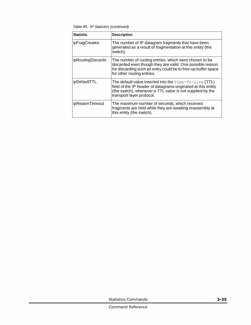
Statistics Commands 3-35
Command Reference
Table 85. IP Statistics (continued)
Statistic Description
ipFragCreates The number of IP datagram fragments that have been generated as a result of fragmentation at this entity (the switch).
ipRoutingDiscards The number of routing entries, which were chosen to be discarded even though they are valid. One possible reason for discarding such an entry could be to free-up buffer space for other routing entries.
ipDefaultTTL The default value inserted into the Time-To-Live (TTL) field of the IP header of datagrams originated at this entity (the switch), whenever a TTL value is not supplied by the transport layer protocol.
ipReasmTimeout The maximum number of seconds, which received fragments are held while they are awaiting reassembly at this entity (the switch).
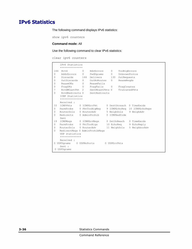
3-36 Statistics Commands
Command Reference
IPv6 Statistics
The following command displays IPv6 statistics:
show ipv6 counters
Command mode: All
Use the following command to clear IPv6 statistics:
clear ipv6 counters
IPv6 Statistics
***************
144 Rcvd 0 HdrErrors 0 TooBigErrors
0 AddrErrors 0 FwdDgrams 0 UnknownProtos
0 Discards 144 Delivers 130 OutRequests
0 OutDiscards 0 OutNoRoutes 0 ReasmReqds
0 ReasmOKs 0 ReasmFails
0 FragOKs 0 FragFails 0 FragCreates
7 RcvdMCastPkt 2 SentMcastPkts 0 TruncatedPkts
0 RcvdRedirects 0 SentRedirects
ICMP Statistics
***************
Received :
33 ICMPPkts 0 ICMPErrPkt 0 DestUnreach 0 TimeExcds
0 ParmProbs 0 PktTooBigMsg 9 ICMPEchoReq 10 ICMPEchoReps
0 RouterSols 0 RouterAdv 5 NeighSols 9 NeighAdv
0 Redirects 0 AdminProhib 0 ICMPBadCode
Sent
19 ICMPMsgs 0 ICMPErrMsgs 0 DstUnReach 0 TimeExcds
0 ParmProbs 0 PktTooBigs 10 EchoReq 9 EchoReply
0 RouterSols 0 RouterAdv 11 NeighSols 5 NeighborAdv
0 RedirectMsgs 0 AdminProhibMsgs
UDP statistics
**************
Received :
0 UDPDgrams 0 UDPNoPorts 0 UDPErrPkts
Sent :
0 UDPDgrams
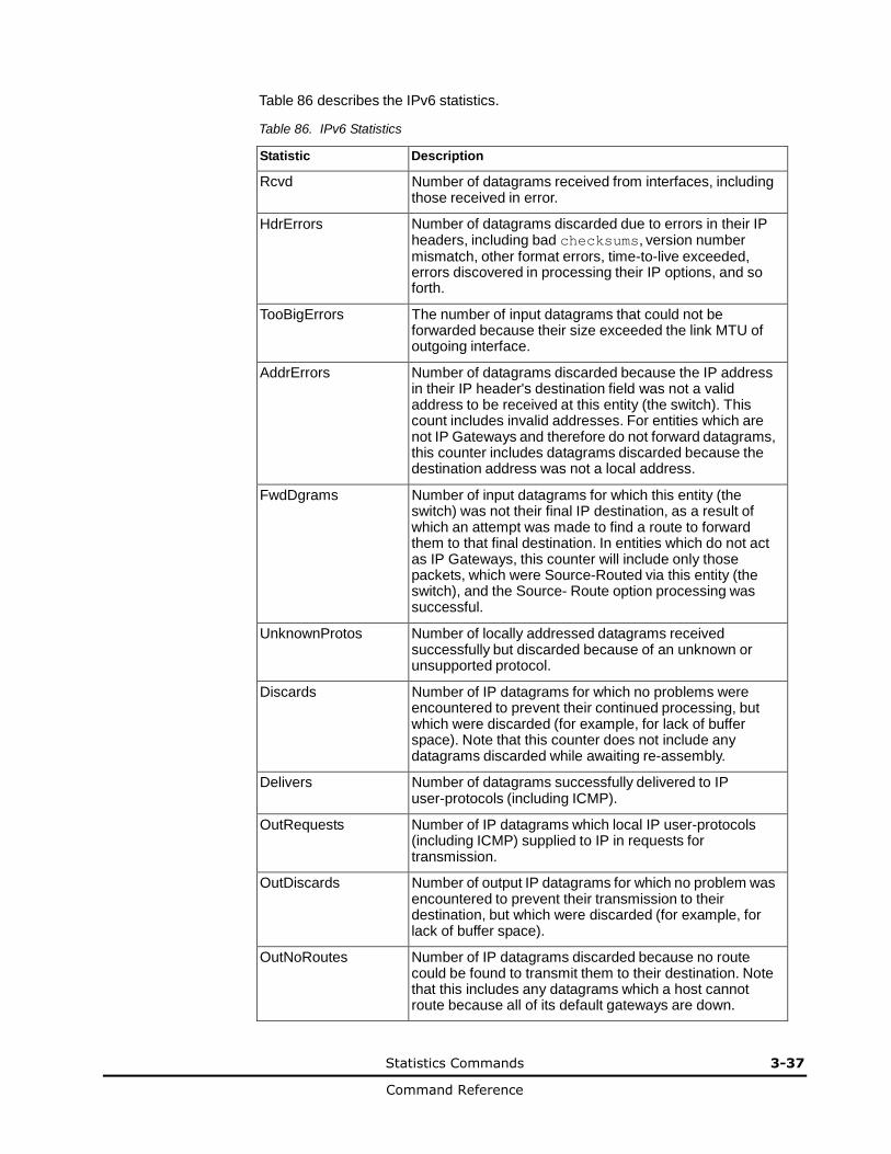
Statistics Commands 3-37
Command Reference
Table 86 describes the IPv6 statistics.
Table 86. IPv6 Statistics
Statistic Description
Rcvd Number of datagrams received from interfaces, including those received in error.
HdrErrors Number of datagrams discarded due to errors in their IP headers, including bad checksums, version number mismatch, other format errors, time-to-live exceeded, errors discovered in processing their IP options, and so forth.
TooBigErrors The number of input datagrams that could not be forwarded because their size exceeded the link MTU of outgoing interface.
AddrErrors Number of datagrams discarded because the IP address in their IP header's destination field was not a valid address to be received at this entity (the switch). This count includes invalid addresses. For entities which are not IP Gateways and therefore do not forward datagrams, this counter includes datagrams discarded because the destination address was not a local address.
FwdDgrams Number of input datagrams for which this entity (the switch) was not their final IP destination, as a result of which an attempt was made to find a route to forward them to that final destination. In entities which do not act as IP Gateways, this counter will include only those packets, which were Source-Routed via this entity (the switch), and the Source- Route option processing was successful.
UnknownProtos Number of locally addressed datagrams received successfully but discarded because of an unknown or unsupported protocol.
Discards Number of IP datagrams for which no problems were encountered to prevent their continued processing, but which were discarded (for example, for lack of buffer space). Note that this counter does not include any datagrams discarded while awaiting re-assembly.
Delivers Number of datagrams successfully delivered to IP user-protocols (including ICMP).
OutRequests Number of IP datagrams which local IP user-protocols (including ICMP) supplied to IP in requests for transmission.
OutDiscards Number of output IP datagrams for which no problem was encountered to prevent their transmission to their destination, but which were discarded (for example, for lack of buffer space).
OutNoRoutes Number of IP datagrams discarded because no route could be found to transmit them to their destination. Note that this includes any datagrams which a host cannot route because all of its default gateways are down.
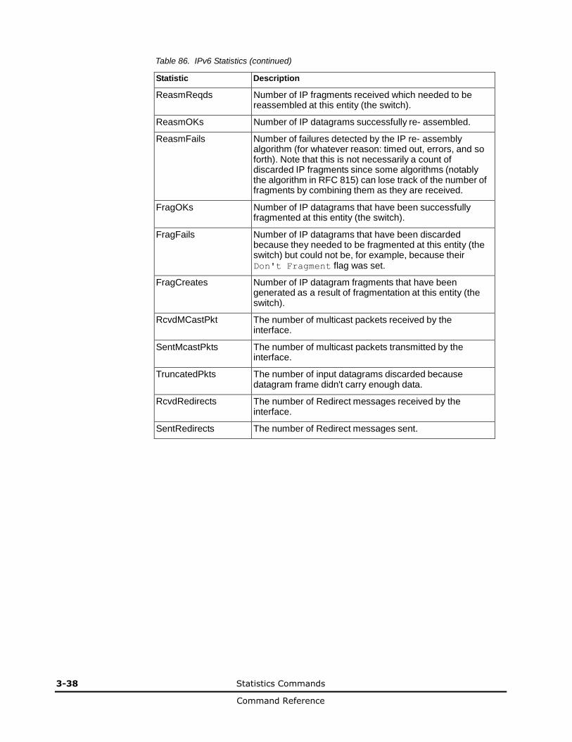
3-38 Statistics Commands
Command Reference
Table 86. IPv6 Statistics (continued)
Statistic Description
ReasmReqds Number of IP fragments received which needed to be reassembled at this entity (the switch).
ReasmOKs Number of IP datagrams successfully re- assembled.
ReasmFails Number of failures detected by the IP re- assembly algorithm (for whatever reason: timed out, errors, and so forth). Note that this is not necessarily a count of discarded IP fragments since some algorithms (notably the algorithm in RFC 815) can lose track of the number of fragments by combining them as they are received.
FragOKs Number of IP datagrams that have been successfully fragmented at this entity (the switch).
FragFails Number of IP datagrams that have been discarded because they needed to be fragmented at this entity (the switch) but could not be, for example, because their Don't Fragment flag was set.
FragCreates Number of IP datagram fragments that have been generated as a result of fragmentation at this entity (the switch).
RcvdMCastPkt The number of multicast packets received by the interface.
SentMcastPkts The number of multicast packets transmitted by the interface.
TruncatedPkts The number of input datagrams discarded because datagram frame didn't carry enough data.
RcvdRedirects The number of Redirect messages received by the interface.
SentRedirects The number of Redirect messages sent.
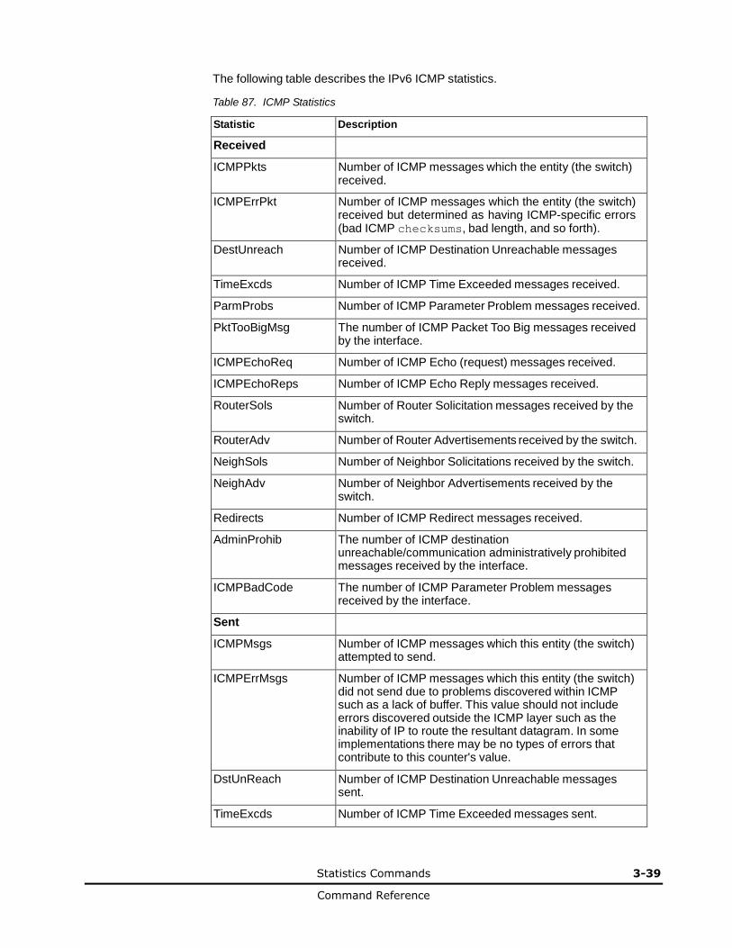
Statistics Commands 3-39
Command Reference
The following table describes the IPv6 ICMP statistics.
Table 87. ICMP Statistics
Statistic Description
Received
ICMPPkts Number of ICMP messages which the entity (the switch) received.
ICMPErrPkt Number of ICMP messages which the entity (the switch) received but determined as having ICMP-specific errors (bad ICMP checksums, bad length, and so forth).
DestUnreach Number of ICMP Destination Unreachable messages received.
TimeExcds Number of ICMP Time Exceeded messages received.
ParmProbs Number of ICMP Parameter Problem messages received.
PktTooBigMsg The number of ICMP Packet Too Big messages received by the interface.
ICMPEchoReq Number of ICMP Echo (request) messages received.
ICMPEchoReps Number of ICMP Echo Reply messages received.
RouterSols Number of Router Solicitation messages received by the switch.
RouterAdv Number of Router Advertisements received by the switch.
NeighSols Number of Neighbor Solicitations received by the switch.
NeighAdv Number of Neighbor Advertisements received by the switch.
Redirects Number of ICMP Redirect messages received.
AdminProhib The number of ICMP destination unreachable/communication administratively prohibited messages received by the interface.
ICMPBadCode The number of ICMP Parameter Problem messages received by the interface.
Sent
ICMPMsgs Number of ICMP messages which this entity (the switch) attempted to send.
ICMPErrMsgs Number of ICMP messages which this entity (the switch) did not send due to problems discovered within ICMP such as a lack of buffer. This value should not include errors discovered outside the ICMP layer such as the inability of IP to route the resultant datagram. In some implementations there may be no types of errors that contribute to this counter's value.
DstUnReach Number of ICMP Destination Unreachable messages sent.
TimeExcds Number of ICMP Time Exceeded messages sent.
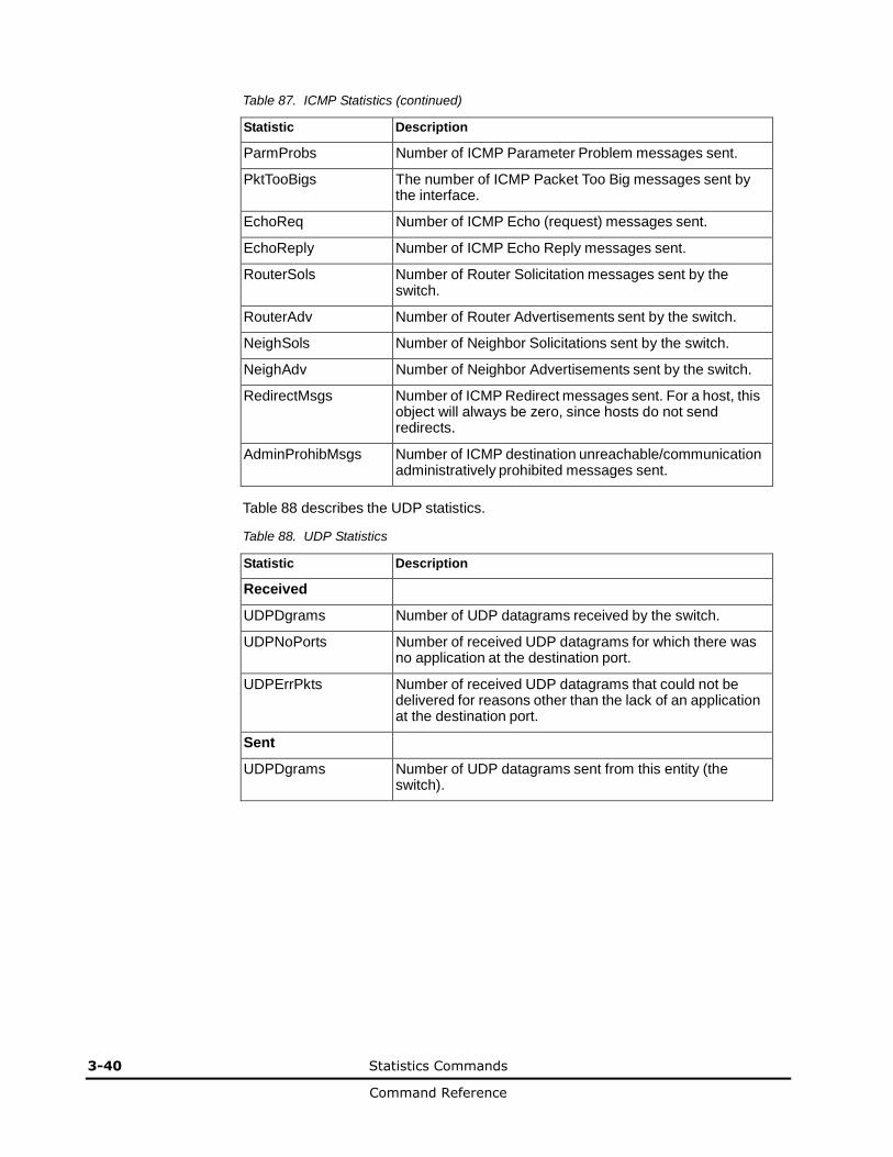
3-40 Statistics Commands
Command Reference
Table 87. ICMP Statistics (continued)
Statistic Description
ParmProbs Number of ICMP Parameter Problem messages sent.
PktTooBigs The number of ICMP Packet Too Big messages sent by the interface.
EchoReq Number of ICMP Echo (request) messages sent.
EchoReply Number of ICMP Echo Reply messages sent.
RouterSols Number of Router Solicitation messages sent by the switch.
RouterAdv Number of Router Advertisements sent by the switch.
NeighSols Number of Neighbor Solicitations sent by the switch.
NeighAdv Number of Neighbor Advertisements sent by the switch.
RedirectMsgs Number of ICMP Redirect messages sent. For a host, this object will always be zero, since hosts do not send redirects.
AdminProhibMsgs Number of ICMP destination unreachable/communication administratively prohibited messages sent.
Table 88 describes the UDP statistics.
Table 88. UDP Statistics
Statistic Description
Received
UDPDgrams Number of UDP datagrams received by the switch.
UDPNoPorts Number of received UDP datagrams for which there was no application at the destination port.
UDPErrPkts Number of received UDP datagrams that could not be delivered for reasons other than the lack of an application at the destination port.
Sent
UDPDgrams Number of UDP datagrams sent from this entity (the switch).
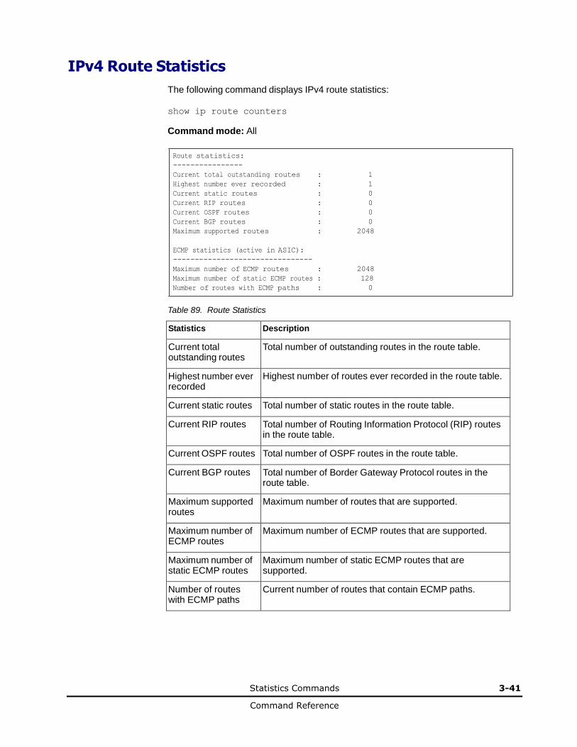
Statistics Commands 3-41
Command Reference
IPv4 Route Statistics
The following command displays IPv4 route statistics:
show ip route counters
Command mode: All
Route statistics:
----------------
Current total outstanding routes : 1
Highest number ever recorded : 1
Current static routes : 0
Current RIP routes : 0
Current OSPF routes : 0
Current BGP routes : 0
Maximum supported routes : 2048
ECMP statistics (active in ASIC):
--------------------------------
Maximum number of ECMP routes : 2048
Maximum number of static ECMP routes : 128
Number of routes with ECMP paths : 0
Table 89. Route Statistics
Statistics Description
Current total outstanding routes
Total number of outstanding routes in the route table.
Highest number ever recorded
Highest number of routes ever recorded in the route table.
Current static routes Total number of static routes in the route table.
Current RIP routes Total number of Routing Information Protocol (RIP) routes in the route table.
Current OSPF routes Total number of OSPF routes in the route table.
Current BGP routes Total number of Border Gateway Protocol routes in the route table.
Maximum supported routes
Maximum number of routes that are supported.
Maximum number of ECMP routes
Maximum number of ECMP routes that are supported.
Maximum number of static ECMP routes
Maximum number of static ECMP routes that are supported.
Number of routes with ECMP paths
Current number of routes that contain ECMP paths.
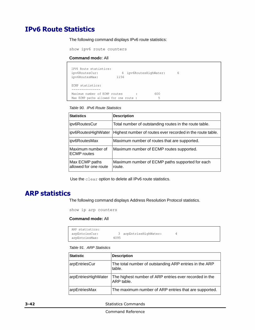
3-42 Statistics Commands
Command Reference
IPv6 Route Statistics
The following command displays IPv6 route statistics:
show ipv6 route counters
Command mode: All
IPV6 Route statistics: ipv6RoutesCur: 4 ipv6RoutesHighWater: 6
ipv6RoutesMax: 1156
ECMP statistics:
---------------
Maximum number of ECMP routes : 600
Max ECMP paths allowed for one route : 5
Table 90. IPv6 Route Statistics
Statistics Description
ipv6RoutesCur Total number of outstanding routes in the route table.
ipv6RoutesHighWater Highest number of routes ever recorded in the route table.
ipv6RoutesMax Maximum number of routes that are supported.
Maximum number of ECMP routes
Maximum number of ECMP routes supported.
Max ECMP paths allowed for one route
Maximum number of ECMP paths supported for each route.
Use the clear option to delete all IPv6 route statistics.
ARP statistics The following command displays Address Resolution Protocol statistics.
show ip arp counters
Command mode: All
ARP statistics:
arpEntriesCur: 3 arpEntriesHighWater: 4
arpEntriesMax: 4095
Table 91. ARP Statistics
Statistic Description
arpEntriesCur The total number of outstanding ARP entries in the ARP table.
arpEntriesHighWater The highest number of ARP entries ever recorded in the ARP table.
arpEntriesMax The maximum number of ARP entries that are supported.
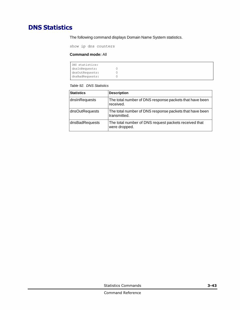
Statistics Commands 3-43
Command Reference
DNS Statistics
The following command displays Domain Name System statistics.
show ip dns counters
Command mode: All
DNS statistics:
dnsInRequests: 0
dnsOutRequests: 0
dnsBadRequests: 0
Table 92. DNS Statistics
Statistics Description
dnsInRequests The total number of DNS response packets that have been received.
dnsOutRequests The total number of DNS response packets that have been transmitted.
dnsBadRequests The total number of DNS request packets received that were dropped.
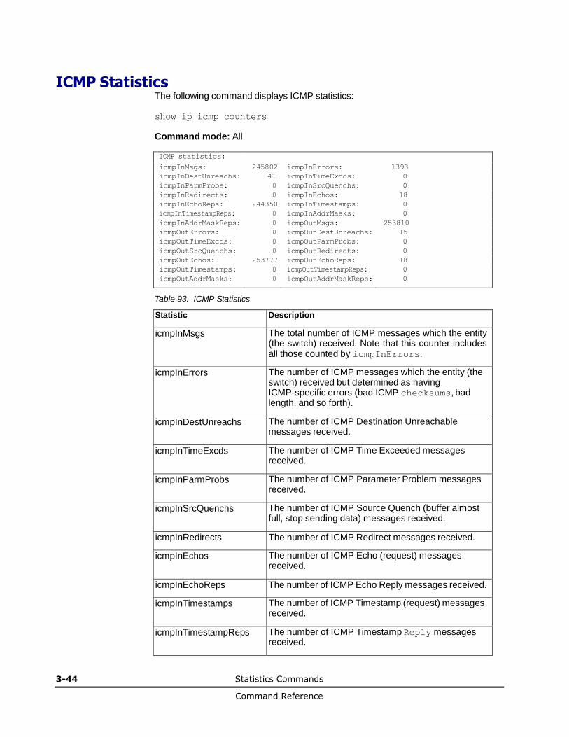
3-44 Statistics Commands
Command Reference
ICMP Statistics The following command displays ICMP statistics:
show ip icmp counters
Command mode: All ICMP statistics: icmpInMsgs: 245802 icmpInErrors: 1393
icmpInDestUnreachs: 41 icmpInTimeExcds: 0
icmpInParmProbs: 0 icmpInSrcQuenchs: 0
icmpInRedirects: 0 icmpInEchos: 18
icmpInEchoReps: 244350 icmpInTimestamps: 0
icmpInTimestampReps: 0 icmpInAddrMasks: 0
icmpInAddrMaskReps: 0 icmpOutMsgs: 253810
icmpOutErrors: 0 icmpOutDestUnreachs: 15
icmpOutTimeExcds: 0 icmpOutParmProbs: 0
icmpOutSrcQuenchs: 0 icmpOutRedirects: 0
icmpOutEchos: 253777 icmpOutEchoReps: 18
icmpOutTimestamps: 0 icmpOutTimestampReps: 0
icmpOutAddrMasks: 0 icmpOutAddrMaskReps: 0
Table 93. ICMP Statistics
Statistic Description
icmpInMsgs The total number of ICMP messages which the entity (the switch) received. Note that this counter includes all those counted by icmpInErrors.
icmpInErrors The number of ICMP messages which the entity (the switch) received but determined as having ICMP-specific errors (bad ICMP checksums, bad length, and so forth).
icmpInDestUnreachs The number of ICMP Destination Unreachable messages received.
icmpInTimeExcds The number of ICMP Time Exceeded messages received.
icmpInParmProbs The number of ICMP Parameter Problem messages received.
icmpInSrcQuenchs The number of ICMP Source Quench (buffer almost full, stop sending data) messages received.
icmpInRedirects The number of ICMP Redirect messages received.
icmpInEchos The number of ICMP Echo (request) messages received.
icmpInEchoReps The number of ICMP Echo Reply messages received.
icmpInTimestamps The number of ICMP Timestamp (request) messages received.
icmpInTimestampReps The number of ICMP Timestamp Reply messages received.
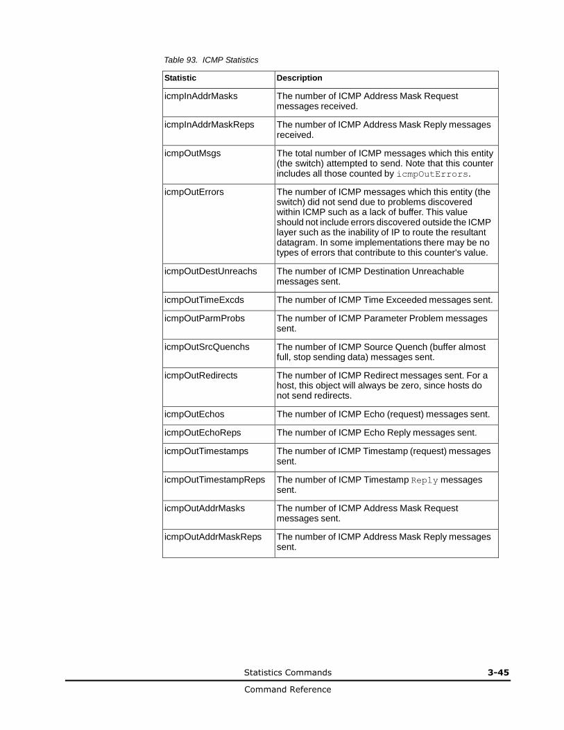
Statistics Commands 3-45
Command Reference
Table 93. ICMP Statistics
Statistic Description
icmpInAddrMasks The number of ICMP Address Mask Request messages received.
icmpInAddrMaskReps The number of ICMP Address Mask Reply messages received.
icmpOutMsgs The total number of ICMP messages which this entity (the switch) attempted to send. Note that this counter includes all those counted by icmpOutErrors.
icmpOutErrors The number of ICMP messages which this entity (the switch) did not send due to problems discovered within ICMP such as a lack of buffer. This value should not include errors discovered outside the ICMP layer such as the inability of IP to route the resultant datagram. In some implementations there may be no types of errors that contribute to this counter's value.
icmpOutDestUnreachs The number of ICMP Destination Unreachable messages sent.
icmpOutTimeExcds The number of ICMP Time Exceeded messages sent.
icmpOutParmProbs The number of ICMP Parameter Problem messages sent.
icmpOutSrcQuenchs The number of ICMP Source Quench (buffer almost full, stop sending data) messages sent.
icmpOutRedirects The number of ICMP Redirect messages sent. For a host, this object will always be zero, since hosts do not send redirects.
icmpOutEchos The number of ICMP Echo (request) messages sent.
icmpOutEchoReps The number of ICMP Echo Reply messages sent.
icmpOutTimestamps The number of ICMP Timestamp (request) messages sent.
icmpOutTimestampReps The number of ICMP Timestamp Reply messages sent.
icmpOutAddrMasks The number of ICMP Address Mask Request messages sent.
icmpOutAddrMaskReps The number of ICMP Address Mask Reply messages sent.
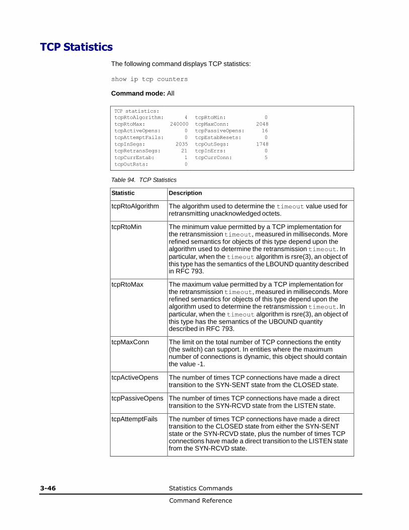
3-46 Statistics Commands
Command Reference
TCP Statistics
The following command displays TCP statistics:
show ip tcp counters
Command mode: All
TCP statistics: tcpRtoAlgorithm: 4 tcpRtoMin: 0
tcpRtoMax: 240000 tcpMaxConn: 2048
tcpActiveOpens: 0 tcpPassiveOpens: 16
tcpAttemptFails: 0 tcpEstabResets: 0
tcpInSegs: 2035 tcpOutSegs: 1748
tcpRetransSegs: 21 tcpInErrs: 0
tcpCurrEstab: 1 tcpCurrConn: 5
tcpOutRsts: 0
Table 94. TCP Statistics
Statistic Description
tcpRtoAlgorithm The algorithm used to determine the timeout value used for retransmitting unacknowledged octets.
tcpRtoMin The minimum value permitted by a TCP implementation for the retransmission timeout, measured in milliseconds. More refined semantics for objects of this type depend upon the algorithm used to determine the retransmission timeout. In particular, when the timeout algorithm is rsre(3), an object of this type has the semantics of the LBOUND quantity described in RFC 793.
tcpRtoMax The maximum value permitted by a TCP implementation for the retransmission timeout, measured in milliseconds. More refined semantics for objects of this type depend upon the algorithm used to determine the retransmission timeout. In particular, when the timeout algorithm is rsre(3), an object of this type has the semantics of the UBOUND quantity described in RFC 793.
tcpMaxConn The limit on the total number of TCP connections the entity (the switch) can support. In entities where the maximum number of connections is dynamic, this object should contain the value -1.
tcpActiveOpens The number of times TCP connections have made a direct transition to the SYN-SENT state from the CLOSED state.
tcpPassiveOpens The number of times TCP connections have made a direct transition to the SYN-RCVD state from the LISTEN state.
tcpAttemptFails The number of times TCP connections have made a direct transition to the CLOSED state from either the SYN-SENT state or the SYN-RCVD state, plus the number of times TCP connections have made a direct transition to the LISTEN state from the SYN-RCVD state.
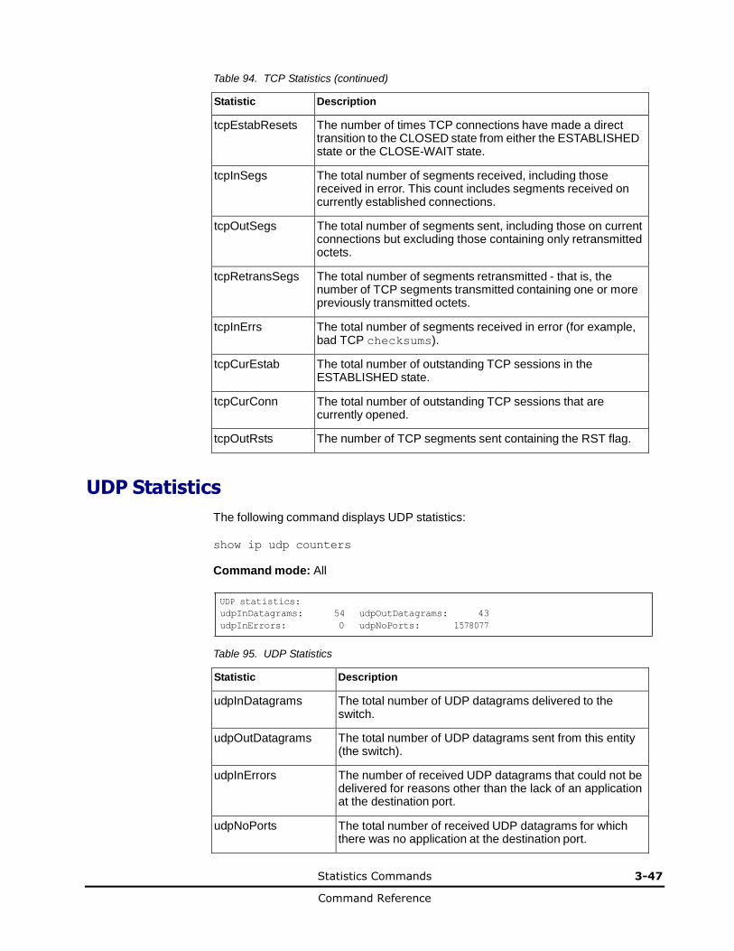
Statistics Commands 3-47
Command Reference
Table 94. TCP Statistics (continued)
Statistic Description
tcpEstabResets The number of times TCP connections have made a direct transition to the CLOSED state from either the ESTABLISHED state or the CLOSE-WAIT state.
tcpInSegs The total number of segments received, including those received in error. This count includes segments received on currently established connections.
tcpOutSegs The total number of segments sent, including those on current connections but excluding those containing only retransmitted octets.
tcpRetransSegs The total number of segments retransmitted - that is, the number of TCP segments transmitted containing one or more previously transmitted octets.
tcpInErrs The total number of segments received in error (for example, bad TCP checksums).
tcpCurEstab The total number of outstanding TCP sessions in the ESTABLISHED state.
tcpCurConn The total number of outstanding TCP sessions that are currently opened.
tcpOutRsts The number of TCP segments sent containing the RST flag.
UDP Statistics
The following command displays UDP statistics:
show ip udp counters
Command mode: All
UDP statistics:
udpInDatagrams: 54 udpOutDatagrams: 43
udpInErrors: 0 udpNoPorts: 1578077
Table 95. UDP Statistics
Statistic Description
udpInDatagrams The total number of UDP datagrams delivered to the switch.
udpOutDatagrams The total number of UDP datagrams sent from this entity (the switch).
udpInErrors The number of received UDP datagrams that could not be delivered for reasons other than the lack of an application at the destination port.
udpNoPorts The total number of received UDP datagrams for which there was no application at the destination port.
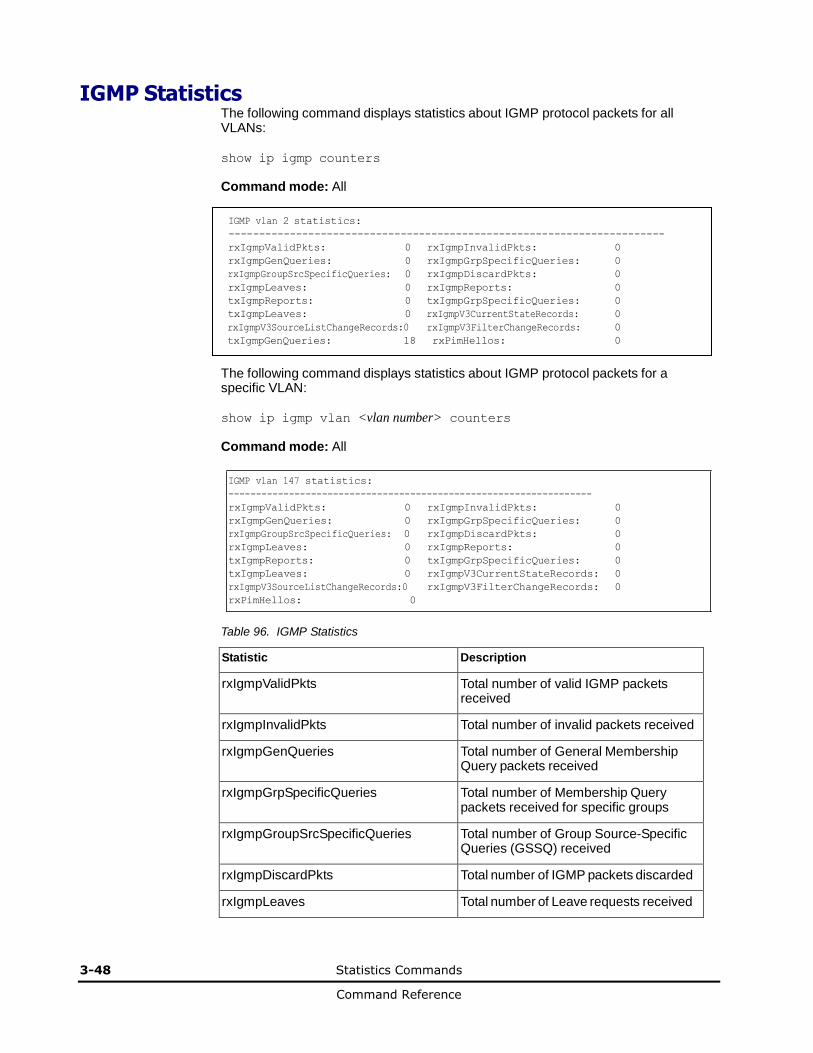
3-48 Statistics Commands
Command Reference
IGMP Statistics The following command displays statistics about IGMP protocol packets for all VLANs:
show ip igmp counters
Command mode: All
IGMP vlan 2 statistics:
-----------------------------------------------------------------------
rxIgmpValidPkts: 0 rxIgmpInvalidPkts: 0
rxIgmpGenQueries: 0 rxIgmpGrpSpecificQueries: 0
rxIgmpGroupSrcSpecificQueries: 0 rxIgmpDiscardPkts: 0
rxIgmpLeaves: 0 rxIgmpReports: 0
txIgmpReports: 0 txIgmpGrpSpecificQueries: 0
txIgmpLeaves: 0 rxIgmpV3CurrentStateRecords: 0
rxIgmpV3SourceListChangeRecords:0 rxIgmpV3FilterChangeRecords: 0
txIgmpGenQueries: 18 rxPimHellos: 0
The following command displays statistics about IGMP protocol packets for a specific VLAN:
show ip igmp vlan <vlan number> counters
Command mode: All
IGMP vlan 147 statistics:
------------------------------------------------------------------
rxIgmpValidPkts: 0 rxIgmpInvalidPkts: 0
rxIgmpGenQueries: 0 rxIgmpGrpSpecificQueries: 0
rxIgmpGroupSrcSpecificQueries: 0 rxIgmpDiscardPkts: 0
rxIgmpLeaves: 0 rxIgmpReports: 0
txIgmpReports: 0 txIgmpGrpSpecificQueries: 0
txIgmpLeaves: 0 rxIgmpV3CurrentStateRecords: 0
rxIgmpV3SourceListChangeRecords:0 rxIgmpV3FilterChangeRecords: 0
rxPimHellos: 0
Table 96. IGMP Statistics
Statistic Description
rxIgmpValidPkts Total number of valid IGMP packets received
rxIgmpInvalidPkts Total number of invalid packets received
rxIgmpGenQueries Total number of General Membership Query packets received
rxIgmpGrpSpecificQueries Total number of Membership Query packets received for specific groups
rxIgmpGroupSrcSpecificQueries Total number of Group Source-Specific Queries (GSSQ) received
rxIgmpDiscardPkts Total number of IGMP packets discarded
rxIgmpLeaves Total number of Leave requests received
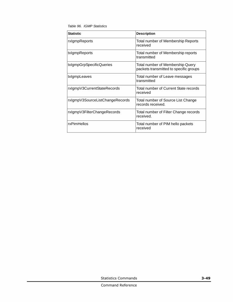
Statistics Commands 3-49
Command Reference
Table 96. IGMP Statistics
Statistic Description
rxIgmpReports Total number of Membership Reports received
txIgmpReports Total number of Membership reports transmitted
txIgmpGrpSpecificQueries Total number of Membership Query packets transmitted to specific groups
txIgmpLeaves Total number of Leave messages transmitted
rxIgmpV3CurrentStateRecords Total number of Current State records received
rxIgmpV3SourceListChangeRecords Total number of Source List Change records received.
rxIgmpV3FilterChangeRecords Total number of Filter Change records received.
rxPimHellos Total number of PIM hello packets received
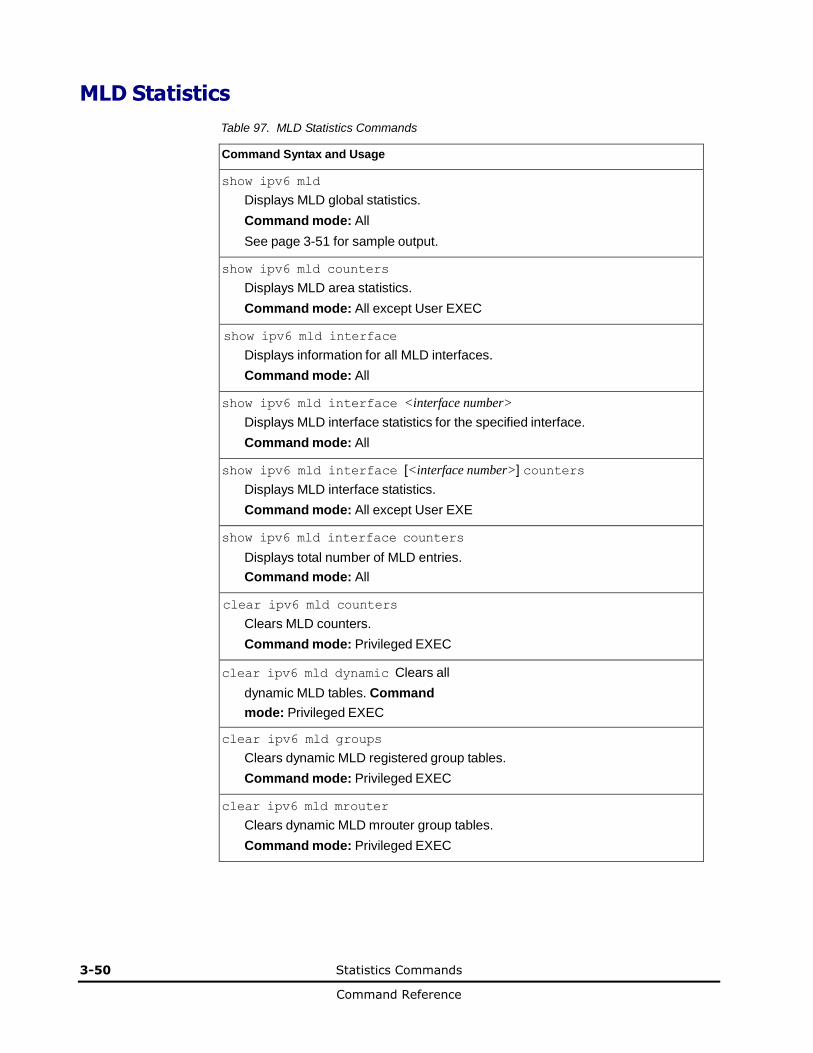
3-50 Statistics Commands
Command Reference
MLD Statistics
Table 97. MLD Statistics Commands
Command Syntax and Usage
show ipv6 mld
Displays MLD global statistics.
Command mode: All
See page 3-51 for sample output.
show ipv6 mld counters
Displays MLD area statistics.
Command mode: All except User EXEC
show ipv6 mld interface
Displays information for all MLD interfaces.
Command mode: All
show ipv6 mld interface <interface number>
Displays MLD interface statistics for the specified interface.
Command mode: All
show ipv6 mld interface [<interface number>] counters
Displays MLD interface statistics.
Command mode: All except User EXE
show ipv6 mld interface counters
Displays total number of MLD entries.
Command mode: All
clear ipv6 mld counters
Clears MLD counters.
Command mode: Privileged EXEC
clear ipv6 mld dynamic Clears all
dynamic MLD tables. Command
mode: Privileged EXEC
clear ipv6 mld groups
Clears dynamic MLD registered group tables.
Command mode: Privileged EXEC
clear ipv6 mld mrouter
Clears dynamic MLD mrouter group tables.
Command mode: Privileged EXEC

Statistics Commands 3-51
Command Reference
MLD Global Statistics
The MLD global statistics displays information for all MLD packets received on all interfaces
show ipv6 mld counters
Command mode: All.
MLD global statistics: ----------------------
Total L3 IPv6 (S, G, V) entries: 2
Total MLD groups: 2
Bad Length: 0
Bad Checksum: 0
Bad Receive If: 0
Receive non-local: 0
Invalid Packets: 4
MLD packet statistics for interfaces:
MLD interface packet statistics for interface 1:
MLD msg type Received Sent RxErrors
------------ -------------------- -------------------- --------------------
General Query 0 1067 0
MAS Query 0 0 0
MASSQ Query 0 0 0
MLDv1 Report 0 0 0
MLDv1 Done 0 0 0
MLDv2 Report 1069 1084 0
INC CSRs(v2) 1 0 0
EXC CSRs(v2) 2134 1093 0
TO_INC FMCRs(v2) 1 0 0
TO_EXC FMCRs(v2) 0 15 0
ALLOW SLCRs(v2) 0 0 0
BLOCK SLCRs(v2) 0 0 0
MLD interface packet statistics for interface 2:
MLD msg type Received Sent RxErrors
------------ -------------------- -------------------- --------------------
MLD interface packet statistics for interface 3:
MLD msg type Received Sent RxErrors
------------ -------------------- -------------------- --------------------
General Query 0 2467 0
MAS Query 0 0 0
MASSQ Query 0 0 0
MLDv1 Report 0 0 0
MLDv1 Done 0 0 0
MLDv2 Report 2 2472 0
INC CSRs(v2) 1 0 0
EXC CSRs(v2) 0 2476 0
TO_INC FMCRs(v2) 0 0 0
TO_EXC FMCRs(v2) 0 8 0
ALLOW SLCRs(v2) 0 0 0
BLOCK SLCRs(v2) 1 0 0
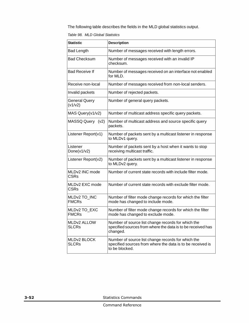
3-52 Statistics Commands
Command Reference
The following table describes the fields in the MLD global statistics output.
Table 98. MLD Global Statistics
Statistic Description
Bad Length Number of messages received with length errors.
Bad Checksum Number of messages received with an invalid IP checksum.
Bad Receive If Number of messages received on an interface not enabled for MLD.
Receive non-local Number of messages received from non-local senders.
Invalid packets Number of rejected packets.
General Query (v1/v2)
Number of general query packets.
MAS Query(v1/v2) Number of multicast address specific query packets.
MASSQ Query (v2) Number of multicast address and source specific query packets.
Listener Report(v1) Number of packets sent by a multicast listener in response to MLDv1 query.
Listener Done(v1/v2)
Number of packets sent by a host when it wants to stop receiving multicast traffic.
Listener Report(v2) Number of packets sent by a multicast listener in response to MLDv2 query.
MLDv2 INC mode CSRs
Number of current state records with include filter mode.
MLDv2 EXC mode CSRs
Number of current state records with exclude filter mode.
MLDv2 TO_INC FMCRs
Number of filter mode change records for which the filter mode has changed to include mode.
MLDv2 TO_EXC FMCRs
Number of filter mode change records for which the filter mode has changed to exclude mode.
MLDv2 ALLOW SLCRs
Number of source list change records for which the specified sources from where the data is to be received has changed.
MLDv2 BLOCK SLCRs
Number of source list change records for which the specified sources from where the data is to be received is to be blocked.
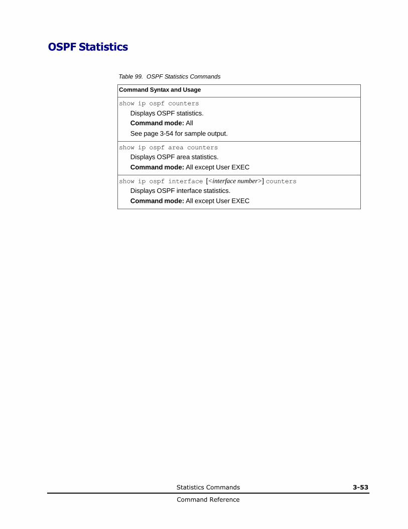
Statistics Commands 3-53
Command Reference
OSPF Statistics
Table 99. OSPF Statistics Commands
Command Syntax and Usage
show ip ospf counters
Displays OSPF statistics.
Command mode: All
See page 3-54 for sample output.
show ip ospf area counters
Displays OSPF area statistics.
Command mode: All except User EXEC
show ip ospf interface [<interface number>] counters
Displays OSPF interface statistics.
Command mode: All except User EXEC
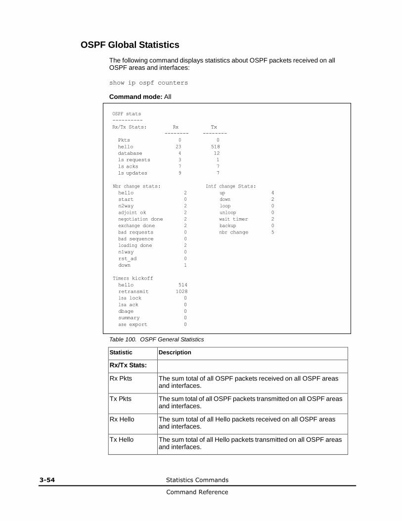
3-54 Statistics Commands
Command Reference
OSPF Global Statistics
The following command displays statistics about OSPF packets received on all OSPF areas and interfaces:
show ip ospf counters
Command mode: All
OSPF stats ----------
Rx/Tx Stats: Rx Tx
-------- --------
Pkts 0 0
hello 23 518
database 4 12
ls requests 3 1
ls acks 7 7
ls updates 9 7
Nbr change stats: Intf change Stats: hello 2 up 4
start 0 down 2
n2way 2 loop 0
adjoint ok 2 unloop 0
negotiation done 2 wait timer 2
exchange done 2 backup 0
bad requests 0 nbr change 5
bad sequence 0 loading done 2 n1way 0 rst_ad 0 down 1
Timers kickoff
hello 514
retransmit 1028
lsa lock 0
lsa ack 0
dbage 0
summary 0
ase export 0
Table 100. OSPF General Statistics
Statistic Description
Rx/Tx Stats:
Rx Pkts The sum total of all OSPF packets received on all OSPF areas and interfaces.
Tx Pkts The sum total of all OSPF packets transmitted on all OSPF areas and interfaces.
Rx Hello The sum total of all Hello packets received on all OSPF areas and interfaces.
Tx Hello The sum total of all Hello packets transmitted on all OSPF areas and interfaces.

Statistics Commands 3-55
Command Reference
Table 100. OSPF General Statistics (continued)
Statistic Description
Rx Database The sum total of all Database Description packets received on all OSPF areas and interfaces.
Tx Database The sum total of all Database Description packets transmitted on all OSPF areas and interfaces.
Rx ls Requests The sum total of all Link State Request packets received on all OSPF areas and interfaces.
Tx ls Requests The sum total of all Link State Request packets transmitted on all OSPF areas and interfaces.
Rx ls Acks The sum total of all Link State Acknowledgement packets received on all OSPF areas and interfaces.
Tx ls Acks The sum total of all Link State Acknowledgement packets transmitted on all OSPF areas and interfaces.
Rx ls Updates The sum total of all Link State Update packets received on all OSPF areas and interfaces.
Tx ls Updates The sum total of all Link State Update packets transmitted on all OSPF areas and interfaces.
Nbr Change Stats:
hello The sum total of all Hello packets received from neighbors on all OSPF areas and interfaces.
Start The sum total number of neighbors in this state (that is, an indication that Hello packets must now be sent to the neighbor at intervals of HelloInterval seconds.) across all OSPF areas and interfaces.
n2way The sum total number of bidirectional communication establishment between this router and other neighboring routers.
adjoint ok The sum total number of decisions to be made (again) as to whether an adjacency should be established/maintained with the neighbor across all OSPF areas and interfaces.
negotiation done
The sum total number of neighbors in this state wherein the Master/slave relationship has been negotiated, and sequence numbers have been exchanged, across all OSPF areas and interfaces.
exchange done
The sum total number of neighbors in this state (that is, in an adjacency's final state) having transmitted a full sequence of Database Description packets across all OSPF areas and interfaces.
bad requests The sum total number of Link State Requests which have been received for a link state advertisement not contained in the database across all interfaces and OSPF areas.
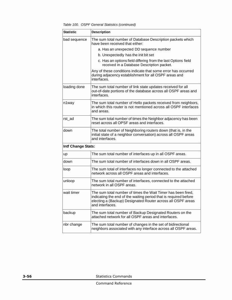
3-56 Statistics Commands
Command Reference
Table 100. OSPF General Statistics (continued)
Statistic Description
bad sequence The sum total number of Database Description packets which have been received that either:
a. Has an unexpected DD sequence number
b. Unexpectedly has the init bit set
c. Has an options field differing from the last Options field received in a Database Description packet.
Any of these conditions indicate that some error has occurred during adjacency establishment for all OSPF areas and interfaces.
loading done The sum total number of link state updates received for all out-of-date portions of the database across all OSPF areas and interfaces.
n1way The sum total number of Hello packets received from neighbors, in which this router is not mentioned across all OSPF interfaces and areas.
rst_ad The sum total number of times the Neighbor adjacency has been reset across all OPSF areas and interfaces.
down The total number of Neighboring routers down (that is, in the initial state of a neighbor conversation) across all OSPF areas and interfaces.
Intf Change Stats:
up The sum total number of interfaces up in all OSPF areas.
down The sum total number of interfaces down in all OSPF areas.
loop The sum total of interfaces no longer connected to the attached network across all OSPF areas and interfaces.
unloop The sum total number of interfaces, connected to the attached network in all OSPF areas.
wait timer The sum total number of times the Wait Timer has been fired, indicating the end of the waiting period that is required before electing a (Backup) Designated Router across all OSPF areas and interfaces.
backup The sum total number of Backup Designated Routers on the attached network for all OSPF areas and interfaces.
nbr change The sum total number of changes in the set of bidirectional neighbors associated with any interface across all OSPF areas.
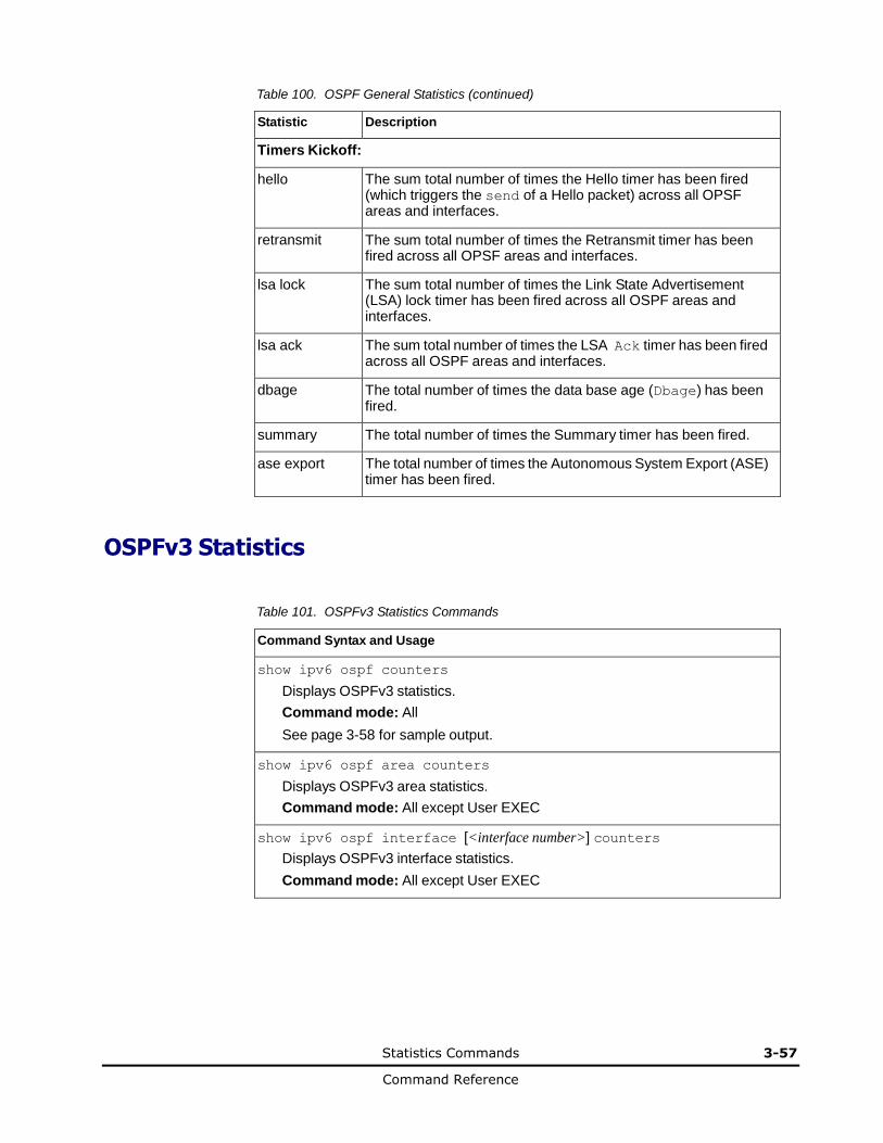
Statistics Commands 3-57
Command Reference
Table 100. OSPF General Statistics (continued)
Statistic Description
Timers Kickoff:
hello The sum total number of times the Hello timer has been fired (which triggers the send of a Hello packet) across all OPSF areas and interfaces.
retransmit The sum total number of times the Retransmit timer has been fired across all OPSF areas and interfaces.
lsa lock The sum total number of times the Link State Advertisement (LSA) lock timer has been fired across all OSPF areas and interfaces.
lsa ack The sum total number of times the LSA Ack timer has been fired across all OSPF areas and interfaces.
dbage The total number of times the data base age (Dbage) has been fired.
summary The total number of times the Summary timer has been fired.
ase export The total number of times the Autonomous System Export (ASE) timer has been fired.
OSPFv3 Statistics
Table 101. OSPFv3 Statistics Commands
Command Syntax and Usage
show ipv6 ospf counters
Displays OSPFv3 statistics.
Command mode: All
See page 3-58 for sample output.
show ipv6 ospf area counters
Displays OSPFv3 area statistics.
Command mode: All except User EXEC
show ipv6 ospf interface [<interface number>] counters
Displays OSPFv3 interface statistics.
Command mode: All except User EXEC

3-58 Statistics Commands
Command Reference
OSPFv3 Global Statistics
The following command displays statistics about OSPFv3 packets received on all OSPFv3 areas and interfaces:
show ipv6 ospf counters
Command mode: All
OSPFv3 stats ----------
Rx/Tx/Disd Stats: Rx Tx Discarded
-------- -------- ---------
Pkts 9695 95933 0
hello 9097 8994 0
database 39 51 6
ls requests 16 8 0
ls acks 172 360 0
ls updates 371 180 0
Nbr change stats: Intf change Stats:
down 0 down 5
attempt 0 loop 0
init 1 waiting 6
n2way 1 ptop 0
exstart 1 dr 4
exchange done 1 backup 6
loading done 1 dr other 0
full 1 all events 33
all events 6
Timers kickoff
hello 8988
wait 6
poll 0
nbr probe 0
Number of LSAs
originated 180
rcvd newer originations 355
The OSPFv3 General Statistics contain the sum total of all OSPF packets received on all OSPFv3 areas and interfaces.
Table 102. OSPFv3 General Statistics
Statistics Description
Rx/Tx Stats:
Rx Pkts The sum total of all OSPFv3 packets received on all OSPFv3 interfaces.
Tx Pkts The sum total of all OSPFv3 packets transmitted on all OSPFv3 interfaces.
Discarded Pkts The sum total of all OSPFv3 packets discarded.
Rx hello The sum total of all Hello packets received on all OSPFv3 interfaces.
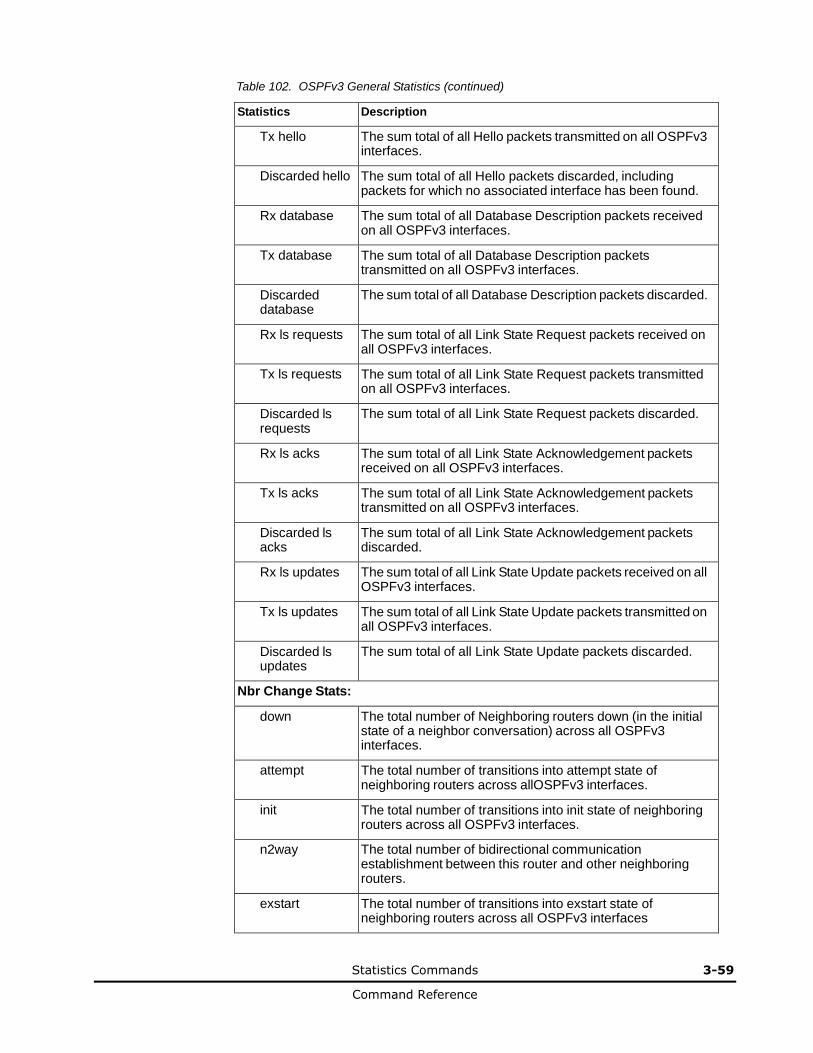
Statistics Commands 3-59
Command Reference
Table 102. OSPFv3 General Statistics (continued)
Statistics Description
Tx hello The sum total of all Hello packets transmitted on all OSPFv3 interfaces.
Discarded hello The sum total of all Hello packets discarded, including packets for which no associated interface has been found.
Rx database The sum total of all Database Description packets received on all OSPFv3 interfaces.
Tx database The sum total of all Database Description packets transmitted on all OSPFv3 interfaces.
Discarded database
The sum total of all Database Description packets discarded.
Rx ls requests The sum total of all Link State Request packets received on all OSPFv3 interfaces.
Tx ls requests The sum total of all Link State Request packets transmitted on all OSPFv3 interfaces.
Discarded ls requests
The sum total of all Link State Request packets discarded.
Rx ls acks The sum total of all Link State Acknowledgement packets received on all OSPFv3 interfaces.
Tx ls acks The sum total of all Link State Acknowledgement packets transmitted on all OSPFv3 interfaces.
Discarded ls acks
The sum total of all Link State Acknowledgement packets discarded.
Rx ls updates The sum total of all Link State Update packets received on all OSPFv3 interfaces.
Tx ls updates The sum total of all Link State Update packets transmitted on all OSPFv3 interfaces.
Discarded ls updates
The sum total of all Link State Update packets discarded.
Nbr Change Stats:
down The total number of Neighboring routers down (in the initial state of a neighbor conversation) across all OSPFv3 interfaces.
attempt The total number of transitions into attempt state of neighboring routers across allOSPFv3 interfaces.
init The total number of transitions into init state of neighboring routers across all OSPFv3 interfaces.
n2way The total number of bidirectional communication establishment between this router and other neighboring routers.
exstart The total number of transitions into exstart state of neighboring routers across all OSPFv3 interfaces
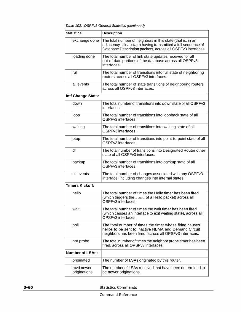
3-60 Statistics Commands
Command Reference
Table 102. OSPFv3 General Statistics (continued)
Statistics Description
exchange done The total number of neighbors in this state (that is, in an adjacency's final state) having transmitted a full sequence of Database Description packets, across all OSPFv3 interfaces.
loading done The total number of link state updates received for all out-of-date portions of the database across all OSPFv3 interfaces.
full The total number of transitions into full state of neighboring routers across all OSPFv3 interfaces.
all events The total number of state transitions of neighboring routers across all OSPFv3 interfaces.
Intf Change Stats:
down The total number of transitions into down state of all OSPFv3 interfaces.
loop The total number of transitions into loopback state of all OSPFv3 interfaces.
waiting The total number of transitions into waiting state of all OSPFv3 interfaces.
ptop The total number of transitions into point-to-point state of all OSPFv3 interfaces.
dr The total number of transitions into Designated Router other state of all OSPFv3 interfaces.
backup The total number of transitions into backup state of all OSPFv3 interfaces.
all events The total number of changes associated with any OSPFv3 interface, including changes into internal states.
Timers Kickoff:
hello The total number of times the Hello timer has been fired (which triggers the send of a Hello packet) across all OSPFv3 interfaces.
wait The total number of times the wait timer has been fired (which causes an interface to exit waiting state), across all OPSFv3 interfaces.
poll The total number of times the timer whose firing causes hellos to be sent to inactive NBMA and Demand Circuit neighbors has been fired, across all OPSFv3 interfaces.
nbr probe The total number of times the neighbor probe timer has been fired, across all OPSFv3 interfaces.
Number of LSAs:
originated The number of LSAs originated by this router.
rcvd newer originations
The number of LSAs received that have been determined to be newer originations.
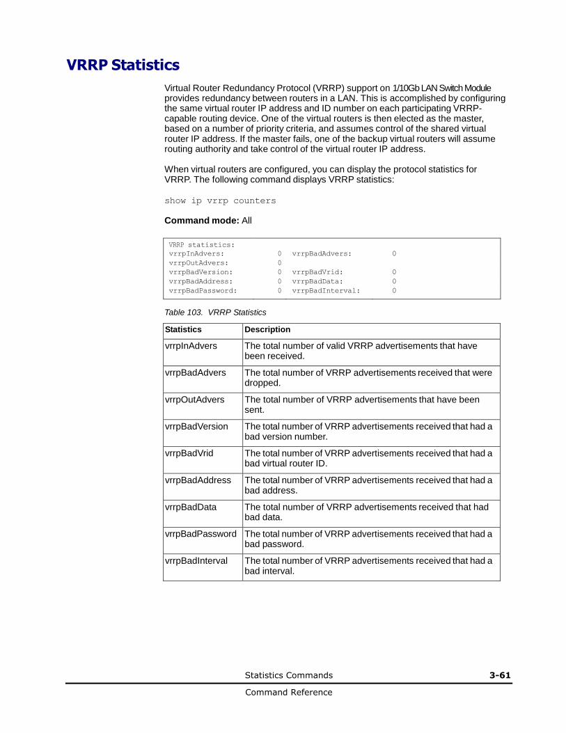
Statistics Commands 3-61
Command Reference
VRRP Statistics
Virtual Router Redundancy Protocol (VRRP) support on 1/10Gb LAN Switch Module
provides redundancy between routers in a LAN. This is accomplished by configuring the same virtual router IP address and ID number on each participating VRRP-capable routing device. One of the virtual routers is then elected as the master, based on a number of priority criteria, and assumes control of the shared virtual router IP address. If the master fails, one of the backup virtual routers will assume routing authority and take control of the virtual router IP address.
When virtual routers are configured, you can display the protocol statistics for VRRP. The following command displays VRRP statistics:
show ip vrrp counters
Command mode: All
VRRP statistics: vrrpInAdvers: 0 vrrpBadAdvers: 0
vrrpOutAdvers: 0 vrrpBadVersion: 0 vrrpBadVrid: 0
vrrpBadAddress: 0 vrrpBadData: 0
vrrpBadPassword: 0 vrrpBadInterval: 0
Table 103. VRRP Statistics
Statistics Description
vrrpInAdvers The total number of valid VRRP advertisements that have been received.
vrrpBadAdvers The total number of VRRP advertisements received that were dropped.
vrrpOutAdvers The total number of VRRP advertisements that have been sent.
vrrpBadVersion The total number of VRRP advertisements received that had a bad version number.
vrrpBadVrid The total number of VRRP advertisements received that had a bad virtual router ID.
vrrpBadAddress The total number of VRRP advertisements received that had a bad address.
vrrpBadData The total number of VRRP advertisements received that had bad data.
vrrpBadPassword The total number of VRRP advertisements received that had a bad password.
vrrpBadInterval The total number of VRRP advertisements received that had a bad interval.
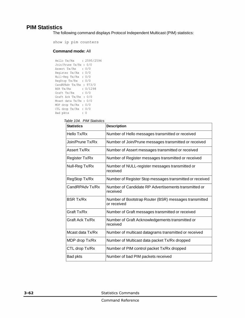
3-62 Statistics Commands
Command Reference
PIM Statistics The following command displays Protocol Independent Multicast (PIM) statistics:
show ip pim counters
Command mode: All
Hello Tx/Rx : 2595/2596
Join/Prune Tx/Rx : 0/0
Assert Tx/Rx : 0/0
Register Tx/Rx : 0/0
Null-Reg Tx/Rx : 0/0
RegStop Tx/Rx : 0/0
CandRPAdv Tx/Rx : 973/0
BSR Tx/Rx : 0/1298
Graft Tx/Rx : 0/0
Graft Ack Tx/Rx : 0/0
Mcast data Tx/Rx : 0/0
MDP drop Tx/Rx : 0/0
CTL drop Tx/Rx : 0/0
Bad pkts : 0
Table 104. PIM Statistics
Statistics Description
Hello Tx/Rx Number of Hello messages transmitted or received
Join/Prune Tx/Rx Number of Join/Prune messages transmitted or received
Assert Tx/Rx Number of Assert messages transmitted or received
Register Tx/Rx Number of Register messages transmitted or received
Null-Reg Tx/Rx Number of NULL-register messages transmitted or
received
RegStop Tx/Rx Number of Register Stop messages transmitted or received
CandRPAdv Tx/Rx Number of Candidate RP Advertisements transmitted or received
BSR Tx/Rx Number of Bootstrap Router (BSR) messages transmitted or received
Graft Tx/Rx Number of Graft messages transmitted or received
Graft Ack Tx/Rx Number of Graft Acknowledgements transmitted or received
Mcast data Tx/Rx Number of multicast datagrams transmitted or received
MDP drop Tx/Rx Number of Multicast data packet Tx/Rx dropped
CTL drop Tx/Rx Number of PIM control packet Tx/Rx dropped
Bad pkts Number of bad PIM packets received
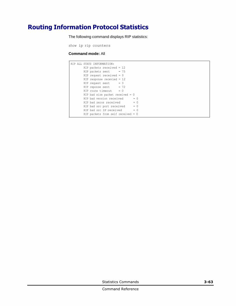
Statistics Commands 3-63
Command Reference
Routing Information Protocol Statistics
The following command displays RIP statistics:
show ip rip counters
Command mode: All
RIP ALL STATS INFORMATION:
RIP packets received = 12
RIP packets sent = 75
RIP request received = 0
RIP response recevied = 12
RIP request sent = 3
RIP reponse sent = 72
RIP route timeout = 0
RIP bad size packet received = 0
RIP bad version received = 0
RIP bad zeros received = 0
RIP bad src port received = 0
RIP bad src IP received = 0
RIP packets from self received = 0
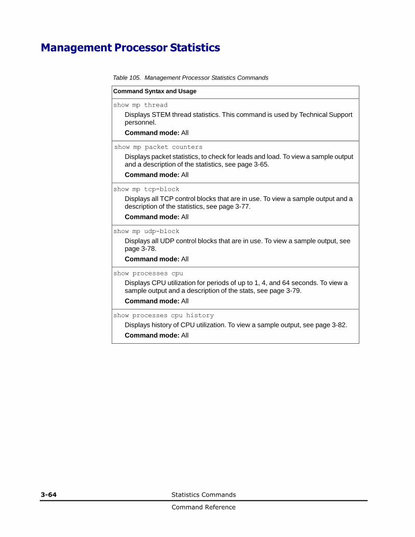
3-64 Statistics Commands
Command Reference
Management Processor Statistics
Table 105. Management Processor Statistics Commands
Command Syntax and Usage
show mp thread
Displays STEM thread statistics. This command is used by Technical Support personnel.
Command mode: All
show mp packet counters
Displays packet statistics, to check for leads and load. To view a sample output and a description of the statistics, see page 3-65.
Command mode: All
show mp tcp-block
Displays all TCP control blocks that are in use. To view a sample output and a description of the statistics, see page 3-77.
Command mode: All
show mp udp-block
Displays all UDP control blocks that are in use. To view a sample output, see page 3-78.
Command mode: All
show processes cpu
Displays CPU utilization for periods of up to 1, 4, and 64 seconds. To view a sample output and a description of the stats, see page 3-79.
Command mode: All
show processes cpu history
Displays history of CPU utilization. To view a sample output, see page 3-82.
Command mode: All
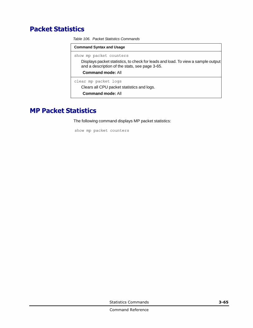
Statistics Commands 3-65
Command Reference
Packet Statistics
Table 106. Packet Statistics Commands
Command Syntax and Usage
show mp packet counters
Displays packet statistics, to check for leads and load. To view a sample output and a description of the stats, see page 3-65.
Command mode: All
clear mp packet logs
Clears all CPU packet statistics and logs.
Command mode: All
MP Packet Statistics
The following command displays MP packet statistics:
show mp packet counters
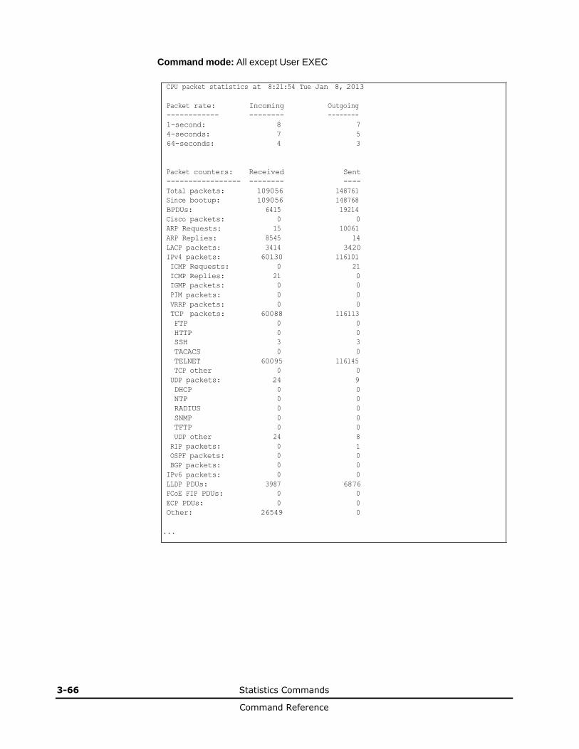
3-66 Statistics Commands
Command Reference
Command mode: All except User EXEC
CPU packet statistics at 8:21:54 Tue Jan 8, 2013
Packet rate: Incoming Outgoing
------------ -------- --------
1-second: 8 7
4-seconds: 7 5
64-seconds: 4 3
Packet counters: Received Sent
----------------- -------- ----
Total packets: 109056 148761
Since bootup: 109056 148768
BPDUs: 6415 19214
Cisco packets: 0 0
ARP Requests: 15 10061
ARP Replies: 8545 14
LACP packets: 3414 3420
IPv4 packets: 60130 116101
ICMP Requests: 0 21
ICMP Replies: 21 0
IGMP packets: 0 0
PIM packets: 0 0
VRRP packets: 0 0
TCP packets: 60088 116113
FTP 0 0
HTTP 0 0
SSH 3 3
TACACS 0 0
TELNET 60095 116145
TCP other 0 0
UDP packets: 24 9
DHCP 0 0
NTP 0 0
RADIUS 0 0
SNMP 0 0
TFTP 0 0
UDP other 24 8
RIP packets: 0 1
OSPF packets: 0 0
BGP packets: 0 0
IPv6 packets: 0 0
LLDP PDUs: 3987 6876
FCoE FIP PDUs: 0 0
ECP PDUs: 0 0
Other: 26549 0
...
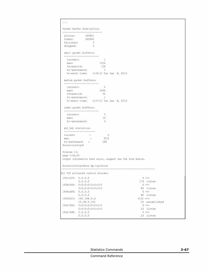
Statistics Commands 3-67
Command Reference
145c1418: 0.0.0.0 0 <=>
0.0.0.0 179 listen
1458cf48: 0:0:0:0:0:0:0:0 0 <=>
0:0:0:0:0:0:0:0 80 listen
1458cdf8: 0.0.0.0 0 <=>
0.0.0.0 80 listen
145d3610: 192.168.0.4 4130 <=>
10.38.5.151 23 established
145a7658: 0:0:0:0:0:0:0:0 0 <=>
0:0:0:0:0:0:0:0 23 listen
145a74d8: 0.0.0.0 0 <=>
0.0.0.0 23 listen
...
Packet Buffer Statistics:
-------------------------
allocs: 265803
frees: 265806
failures: 0
dropped: 0
small packet buffers:
----------------------
current: 1 max: 1024 threshold: 128 hi-watermark: 3 hi-water time: 3:39:12 Tue Jan 8, 2013
medium packet buffers:
----------------------
current: 0 max: 2048 threshold: 50 hi-watermark: 1 hi-water time: 3:37:12 Tue Jan 8, 2013
jumbo packet buffers:
----------------------
current: 0
max: 16
hi-watermark: 0
pkt_hdr statistics:
----------------------
current : 0
max : 3072
hi-watermark : 180
Router(config)#
Problem 11:
page 3-64,65
output information have error, suggest use the form below.
Router(config)#show mp tcp-block
------------------------------------------------------------------
All TCP allocated control blocks:
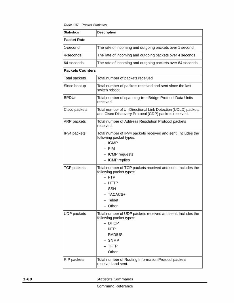
3-68 Statistics Commands
Command Reference
Table 107. Packet Statistics
Statistics Description
Packet Rate
1-second The rate of incoming and outgoing packets over 1 second.
4-seconds The rate of incoming and outgoing packets over 4 seconds.
64-seconds The rate of incoming and outgoing packets over 64 seconds.
Packets Counters
Total packets Total number of packets received
Since bootup Total number of packets received and sent since the last switch reboot.
BPDUs Total number of spanning-tree Bridge Protocol Data Units received.
Cisco packets Total number of UniDirectional Link Detection (UDLD) packets and Cisco Discovery Protocol (CDP) packets received.
ARP packets Total number of Address Resolution Protocol packets received.
IPv4 packets Total number of IPv4 packets received and sent. Includes the following packet types:
– IGMP
– PIM
– ICMP requests
– ICMP replies
TCP packets Total number of TCP packets received and sent. Includes the following packet types:
– FTP
– HTTP
– SSH
– TACACS+
– Telnet
– Other
UDP packets Total number of UDP packets received and sent. Includes the following packet types:
– DHCP
– NTP
– RADIUS
– SNMP
– TFTP
– Other
RIP packets Total number of Routing Information Protocol packets received and sent.
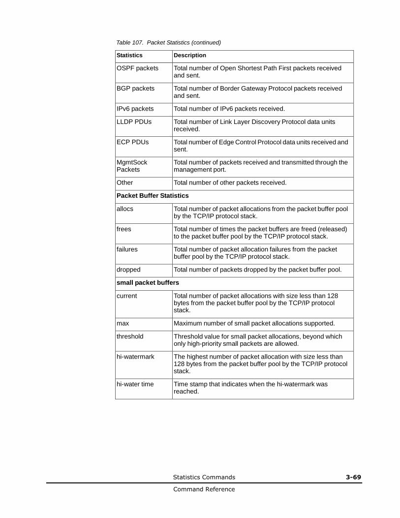
Statistics Commands 3-69
Command Reference
Table 107. Packet Statistics (continued)
Statistics Description
OSPF packets Total number of Open Shortest Path First packets received and sent.
BGP packets Total number of Border Gateway Protocol packets received and sent.
IPv6 packets Total number of IPv6 packets received.
LLDP PDUs Total number of Link Layer Discovery Protocol data units received.
ECP PDUs Total number of Edge Control Protocol data units received and sent.
MgmtSock Packets
Total number of packets received and transmitted through the management port.
Other Total number of other packets received.
Packet Buffer Statistics
allocs Total number of packet allocations from the packet buffer pool by the TCP/IP protocol stack.
frees Total number of times the packet buffers are freed (released) to the packet buffer pool by the TCP/IP protocol stack.
failures Total number of packet allocation failures from the packet buffer pool by the TCP/IP protocol stack.
dropped Total number of packets dropped by the packet buffer pool.
small packet buffers
current Total number of packet allocations with size less than 128 bytes from the packet buffer pool by the TCP/IP protocol stack.
max Maximum number of small packet allocations supported.
threshold Threshold value for small packet allocations, beyond which only high-priority small packets are allowed.
hi-watermark The highest number of packet allocation with size less than 128 bytes from the packet buffer pool by the TCP/IP protocol stack.
hi-water time Time stamp that indicates when the hi-watermark was reached.

3-70 Statistics Commands
Command Reference
Table 107. Packet Statistics (continued)
Statistics Description
medium packet buffers
current Total number of packet allocations with size between 128 to 1536 bytes from the packet buffer pool by the TCP/IP protocol stack.
max Maximum number of medium packet allocations supported.
threshold Threshold value for medium packet allocations, beyond which only high-priority medium packets are allowed.
hi-watermark The highest number of packet allocation with size between 128 to 1536 bytes from the packet buffer pool by the TCP/IP protocol stack.
hi-water time Time stamp that indicates when the hi-watermark was reached.
jumbo packet buffers
current Total number of packet allocations with more than 1536 bytes from the packet buffer pool by the TCP/IP protocol stack.
max Maximum number of jumbo packet allocations supported.
hi-watermark The highest number of packet allocation with more than 1536 bytes from the packet buffer pool by the TCP/IP protocol stack.
pkt_hdr statistics
current Total number of packet allocations with more than 1536 bytes from the packet buffer pool by the TCP/IP protocol stack.
max Maximum number of packet allocations with more than 1536 bytes from the packet buffer pool by the TCP/IP protocol stack.
hi-watermark The highest number of packet allocation with more than 1536 bytes from the packet buffer pool by the TCP/IP protocol stack.
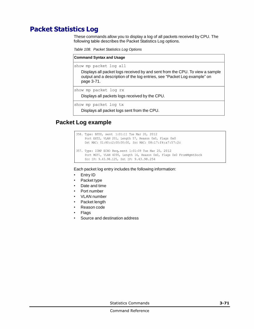
Statistics Commands 3-71
Command Reference
Packet Statistics Log These commands allow you to display a log of all packets received by CPU. The following table describes the Packet Statistics Log options.
Table 108. Packet Statistics Log Options
Command Syntax and Usage
show mp packet log all
Displays all packet logs received by and sent from the CPU. To view a sample output and a description of the log entries, see “Packet Log example” on page 3-71.
show mp packet log rx
Displays all packets logs received by the CPU.
show mp packet log tx
Displays all packet logs sent from the CPU.
Packet Log example
358. Type: BPDU, sent 1:01:11 Tue Mar 20, 2012
Port EXT2, VLAN 201, Length 57, Reason 0x0, Flags 0x0
Dst MAC: 01:80:c2:00:00:00, Src MAC: 08:17:f4:a7:57:2c
357. Type: ICMP ECHO Req,sent 1:01:09 Tue Mar 20, 2012
Port MGT1, VLAN 4095, Length 16, Reason 0x0, Flags 0x0 FromMgmtSock
Src IP: 9.43.98.125, Dst IP: 9.43.98.254
Each packet log entry includes the following information:
• Entry ID
• Packet type
• Date and time
• Port number
• VLAN number
• Packet length
• Reason code
• Flags
• Source and destination address
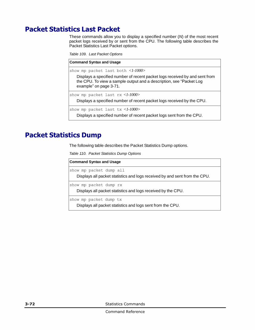
3-72 Statistics Commands
Command Reference
Packet Statistics Last Packet These commands allow you to display a specified number (N) of the most recent packet logs received by or sent from the CPU. The following table describes the Packet Statistics Last Packet options.
Table 109. Last Packet Options
Command Syntax and Usage
show mp packet last both <1-1000>
Displays a specified number of recent packet logs received by and sent from the CPU. To view a sample output and a description, see “Packet Log example” on page 3-71.
show mp packet last rx <1-1000>
Displays a specified number of recent packet logs received by the CPU.
show mp packet last tx <1-1000>
Displays a specified number of recent packet logs sent from the CPU.
Packet Statistics Dump
The following table describes the Packet Statistics Dump options.
Table 110. Packet Statistics Dump Options
Command Syntax and Usage
show mp packet dump all
Displays all packet statistics and logs received by and sent from the CPU.
show mp packet dump rx
Displays all packet statistics and logs received by the CPU.
show mp packet dump tx
Displays all packet statistics and logs sent from the CPU.
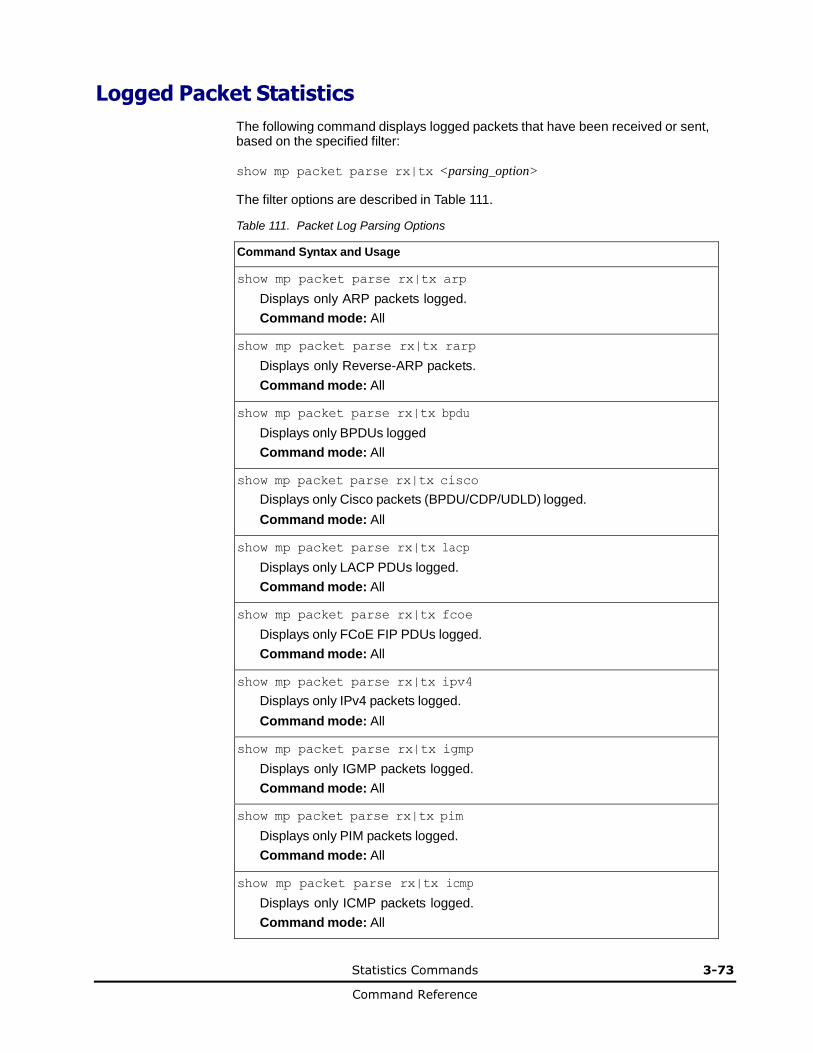
Statistics Commands 3-73
Command Reference
Logged Packet Statistics
The following command displays logged packets that have been received or sent, based on the specified filter:
show mp packet parse rx|tx <parsing_option>
The filter options are described in Table 111.
Table 111. Packet Log Parsing Options
Command Syntax and Usage
show mp packet parse rx|tx arp
Displays only ARP packets logged.
Command mode: All
show mp packet parse rx|tx rarp
Displays only Reverse-ARP packets.
Command mode: All
show mp packet parse rx|tx bpdu
Displays only BPDUs logged
Command mode: All
show mp packet parse rx|tx cisco
Displays only Cisco packets (BPDU/CDP/UDLD) logged.
Command mode: All
show mp packet parse rx|tx lacp
Displays only LACP PDUs logged.
Command mode: All
show mp packet parse rx|tx fcoe
Displays only FCoE FIP PDUs logged.
Command mode: All
show mp packet parse rx|tx ipv4
Displays only IPv4 packets logged.
Command mode: All
show mp packet parse rx|tx igmp
Displays only IGMP packets logged.
Command mode: All
show mp packet parse rx|tx pim
Displays only PIM packets logged.
Command mode: All
show mp packet parse rx|tx icmp
Displays only ICMP packets logged.
Command mode: All
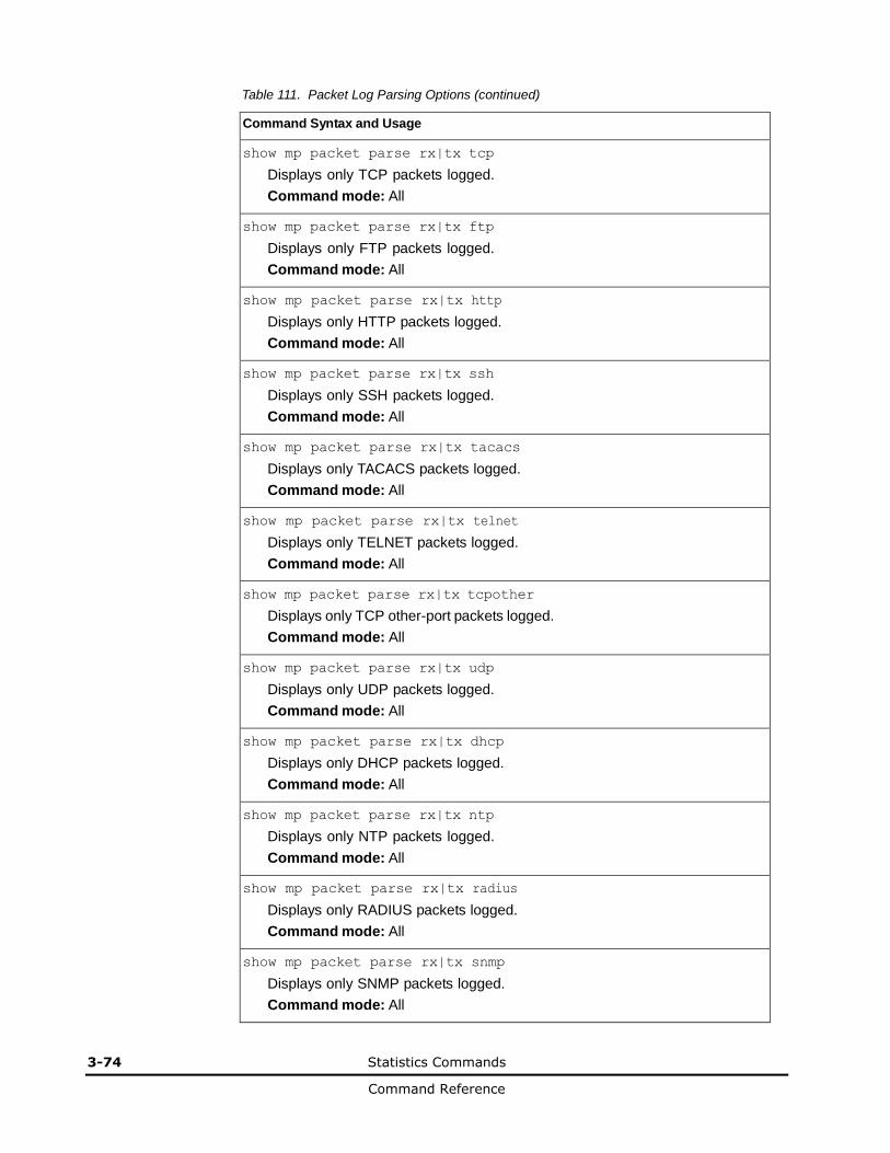
3-74 Statistics Commands
Command Reference
Table 111. Packet Log Parsing Options (continued)
Command Syntax and Usage
show mp packet parse rx|tx tcp
Displays only TCP packets logged.
Command mode: All
show mp packet parse rx|tx ftp
Displays only FTP packets logged.
Command mode: All
show mp packet parse rx|tx http
Displays only HTTP packets logged.
Command mode: All
show mp packet parse rx|tx ssh
Displays only SSH packets logged.
Command mode: All
show mp packet parse rx|tx tacacs
Displays only TACACS packets logged.
Command mode: All
show mp packet parse rx|tx telnet
Displays only TELNET packets logged.
Command mode: All
show mp packet parse rx|tx tcpother
Displays only TCP other-port packets logged.
Command mode: All
show mp packet parse rx|tx udp
Displays only UDP packets logged.
Command mode: All
show mp packet parse rx|tx dhcp
Displays only DHCP packets logged.
Command mode: All
show mp packet parse rx|tx ntp
Displays only NTP packets logged.
Command mode: All
show mp packet parse rx|tx radius
Displays only RADIUS packets logged.
Command mode: All
show mp packet parse rx|tx snmp
Displays only SNMP packets logged.
Command mode: All
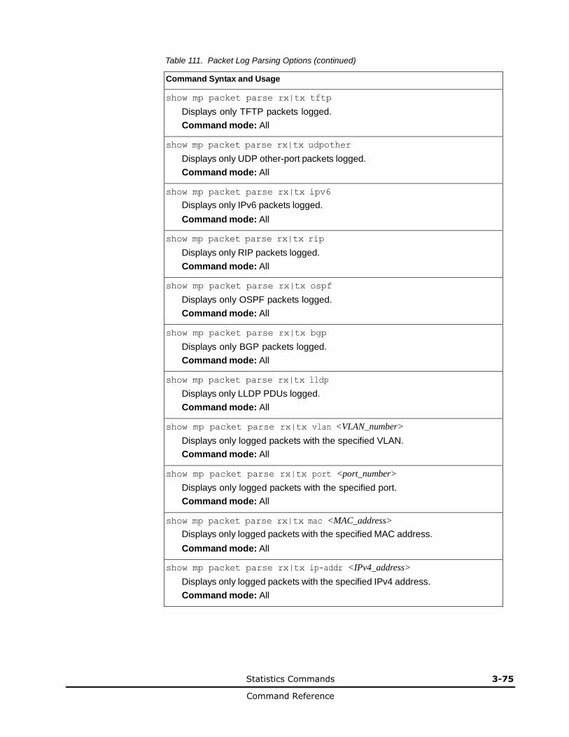
Statistics Commands 3-75
Command Reference
Table 111. Packet Log Parsing Options (continued)
Command Syntax and Usage
show mp packet parse rx|tx tftp
Displays only TFTP packets logged.
Command mode: All
show mp packet parse rx|tx udpother
Displays only UDP other-port packets logged.
Command mode: All
show mp packet parse rx|tx ipv6
Displays only IPv6 packets logged.
Command mode: All
show mp packet parse rx|tx rip
Displays only RIP packets logged.
Command mode: All
show mp packet parse rx|tx ospf
Displays only OSPF packets logged.
Command mode: All
show mp packet parse rx|tx bgp
Displays only BGP packets logged.
Command mode: All
show mp packet parse rx|tx lldp
Displays only LLDP PDUs logged.
Command mode: All
show mp packet parse rx|tx vlan <VLAN_number>
Displays only logged packets with the specified VLAN.
Command mode: All
show mp packet parse rx|tx port <port_number>
Displays only logged packets with the specified port.
Command mode: All
show mp packet parse rx|tx mac <MAC_address>
Displays only logged packets with the specified MAC address.
Command mode: All
show mp packet parse rx|tx ip-addr <IPv4_address>
Displays only logged packets with the specified IPv4 address.
Command mode: All
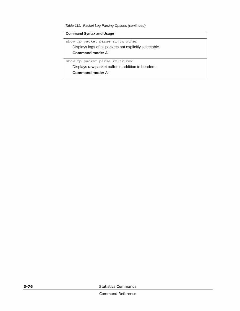
3-76 Statistics Commands
Command Reference
Table 111. Packet Log Parsing Options (continued)
Command Syntax and Usage
show mp packet parse rx|tx other
Displays logs of all packets not explicitly selectable.
Command mode: All
show mp packet parse rx|tx raw
Displays raw packet buffer in addition to headers.
Command mode: All
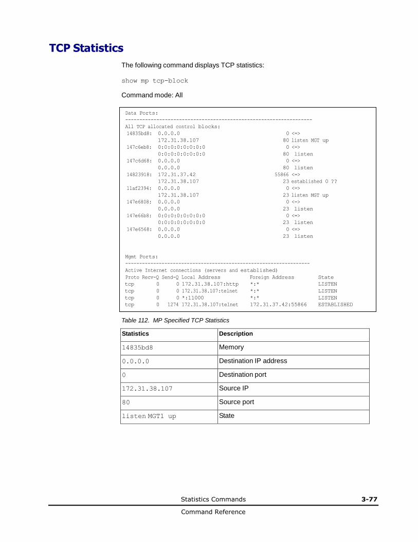
Statistics Commands 3-77
Command Reference
14835bd8: 0.0.0.0 0 <=>
172.31.38.107 80 listen MGT up
147c6eb8: 0:0:0:0:0:0:0:0 0 <=>
0:0:0:0:0:0:0:0 80 listen
147c6d68: 0.0.0.0 0 <=>
0.0.0.0 80 listen
14823918: 172.31.37.42 55866 <=>
172.31.38.107 23 established 0 ??
11af2394: 0.0.0.0 0 <=>
172.31.38.107 23 listen MGT up
147e6808: 0.0.0.0 0 <=>
0.0.0.0 23 listen
147e66b8: 0:0:0:0:0:0:0:0 0 <=>
0:0:0:0:0:0:0:0 23 listen
147e6568: 0.0.0.0 0 <=>
0.0.0.0 23 listen
TCP Statistics
The following command displays TCP statistics:
show mp tcp-block
Command mode: All
Data Ports:
------------------------------------------------------------------
All TCP allocated control blocks:
Mgmt Ports:
------------------------------------------------------------------
Active Internet connections (servers and established)
Proto Recv-Q Send-Q Local Address Foreign Address State
tcp 0 0 172.31.38.107:http *:* LISTEN
tcp 0 0 172.31.38.107:telnet *:* LISTEN
tcp 0 0 *:11000 *:* LISTEN
tcp 0 1274 172.31.38.107:telnet 172.31.37.42:55866 ESTABLISHED
Table 112. MP Specified TCP Statistics
Statistics Description
14835bd8 Memory
0.0.0.0 Destination IP address
0 Destination port
172.31.38.107 Source IP
80 Source port
listen MGT1 up State

3-78 Statistics Commands
Command Reference
UDP Statistics
The following command displays UDP statistics:
show mp udp-block
Command mode: All except User EXEC
Data Ports:
------------------------------------------------------------------
All UDP allocated control blocks:
68: listen
161: listen
500: listen
546: listen
Mgmt Ports:
------------------------------------------------------------------
Active Internet connections (servers and established)
Proto Recv-Q Send-Q Local Address Foreign Address State
udp 0 0 9.43.95.121:snmp *:*
0.0.0.0 0 <=> 9.43.95.121 161 accept MGT1 up
CPU Statistics
The following commands display CPU utilization statistics:
show mp cpu
Command mode: All
CPU utilization Highest Thread Time
------------------------------ ------- ---------- -------------------------
cpuUtil1Second: 3% 83% 58 (I2C ) 12:02:14 Fri Oct 14, 2011
cpuUtil4Seconds: 5%
cpuUtil64Seconds: 5%
Table 113. CPU Statistics
Statistics Description
cpuUtil1Second The use of MP CPU over 1 second. It shows the percentage, highest rate, thread, and time the highest utilization occurred.
cpuUtil4Seconds The use of MP CPU over 4 seconds. It shows the percentage.
cpuUtil64Seconds The use of MP CPU over 64 seconds. It shows the percentage.
Highest The highest percent of CPU use.
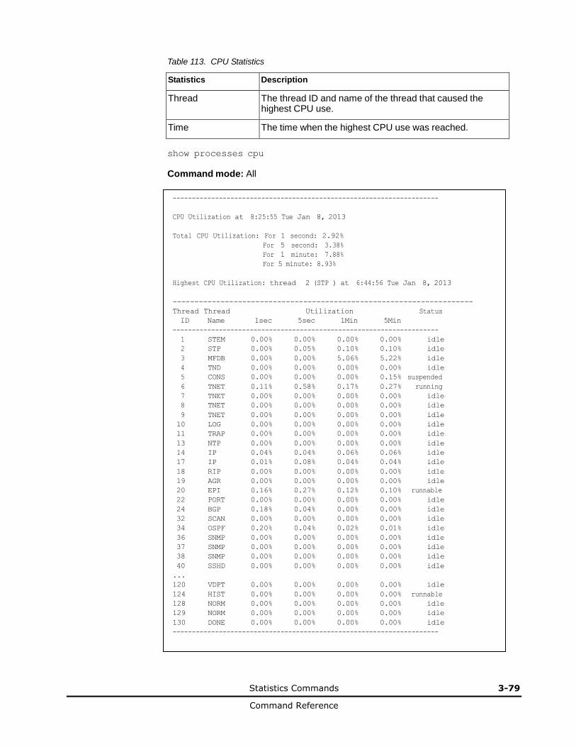
Statistics Commands 3-79
Command Reference
Table 113. CPU Statistics
Statistics Description
Thread The thread ID and name of the thread that caused the highest CPU use.
Time The time when the highest CPU use was reached.
show processes cpu
Command mode: All
---------------------------------------------------------------------
CPU Utilization at 8:25:55 Tue Jan 8, 2013
Total CPU Utilization: For 1 second: 2.92%
For 5 second: 3.38%
For 1 minute: 7.88%
For 5 minute: 8.93%
Highest CPU Utilization: thread 2 (STP ) at 6:44:56 Tue Jan 8, 2013
---------------------------------------------------------------------
Thread Thread Utilization Status
ID Name 1sec 5sec 1Min 5Min ---------------------------------------------------------------------
1 STEM 0.00% 0.00% 0.00% 0.00% idle
2 STP 0.00% 0.05% 0.10% 0.10% idle
3 MFDB 0.00% 0.00% 5.06% 5.22% idle
4 TND 0.00% 0.00% 0.00% 0.00% idle
5 CONS 0.00% 0.00% 0.00% 0.15% suspended
6 TNET 0.11% 0.58% 0.17% 0.27% running
7 TNET 0.00% 0.00% 0.00% 0.00% idle
8 TNET 0.00% 0.00% 0.00% 0.00% idle
9 TNET 0.00% 0.00% 0.00% 0.00% idle
10 LOG 0.00% 0.00% 0.00% 0.00% idle
11 TRAP 0.00% 0.00% 0.00% 0.00% idle
13 NTP 0.00% 0.00% 0.00% 0.00% idle
14 IP 0.04% 0.04% 0.06% 0.06% idle
17 IP 0.01% 0.08% 0.04% 0.04% idle
18 RIP 0.00% 0.00% 0.00% 0.00% idle
19 AGR 0.00% 0.00% 0.00% 0.00% idle
20 EPI 0.16% 0.27% 0.12% 0.10% runnable
22 PORT 0.00% 0.00% 0.00% 0.00% idle
24 BGP 0.18% 0.04% 0.00% 0.00% idle
32 SCAN 0.00% 0.00% 0.00% 0.00% idle
34 OSPF 0.20% 0.04% 0.02% 0.01% idle
36 SNMP 0.00% 0.00% 0.00% 0.00% idle
37 SNMP 0.00% 0.00% 0.00% 0.00% idle
38 SNMP 0.00% 0.00% 0.00% 0.00% idle
40 SSHD 0.00% 0.00% 0.00% 0.00% idle
... 120 VDPT 0.00% 0.00% 0.00% 0.00% idle
124 HIST 0.00% 0.00% 0.00% 0.00% runnable
128 NORM 0.00% 0.00% 0.00% 0.00% idle
129 NORM 0.00% 0.00% 0.00% 0.00% idle
130 DONE 0.00% 0.00% 0.00% 0.00% idle
---------------------------------------------------------------------

3-80 Statistics Commands
Command Reference
Table 114. CPU Statistics
Statistics Description
Thread ID The thread ID number.
Thread Name The name of the thread.
1sec The percent of CPU use over 1 second.
5sec The percent of CPU use over 5 seconds.
1Min The percent of CPU use over 1 minute.
5Min The percent of CPU use over 5 minutes.
Status The status of the process.
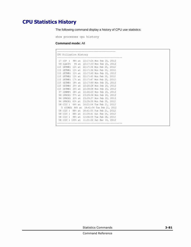
Statistics Commands 3-81
Command Reference
CPU Statistics History
The following command display a history of CPU use statistics:
show processes cpu history
Command mode: All
---------------------------------------------
CPU Utilization History
---------------------------------------------
17 (IP ) 98% at 22:17:24 Mon Feb 20, 2012
59 (LACP) 9% at 22:17:33 Mon Feb 20, 2012
110 (ETMR) 12% at 22:17:34 Mon Feb 20, 2012
110 (ETMR) 12% at 22:17:36 Mon Feb 20, 2012
110 (ETMR) 12% at 22:17:40 Mon Feb 20, 2012
110 (ETMR) 12% at 22:17:45 Mon Feb 20, 2012
110 (ETMR) 17% at 22:17:47 Mon Feb 20, 2012
110 (ETMR) 18% at 22:17:49 Mon Feb 20, 2012
110 (ETMR) 25% at 22:20:28 Mon Feb 20, 2012
110 (ETMR) 26% at 22:39:08 Mon Feb 20, 2012
37 (SNMP) 28% at 22:46:20 Mon Feb 20, 2012
94 (PROX) 57% at 23:29:36 Mon Feb 20, 2012
94 (PROX) 63% at 23:29:37 Mon Feb 20, 2012
94 (PROX) 63% at 23:29:39 Mon Feb 20, 2012
58 (I2C ) 64% at 16:21:54 Tue Feb 21, 2012
5 (CONS) 86% at 18:41:54 Tue Feb 21, 2012
58 (I2C ) 88% at 18:41:55 Tue Feb 21, 2012
58 (I2C ) 88% at 21:29:41 Sat Feb 25, 2012
58 (I2C ) 98% at 12:04:59 Tue Feb 28, 2012
58 (I2C ) 100% at 11:31:32 Sat Mar 10, 2012
---------------------------------------------
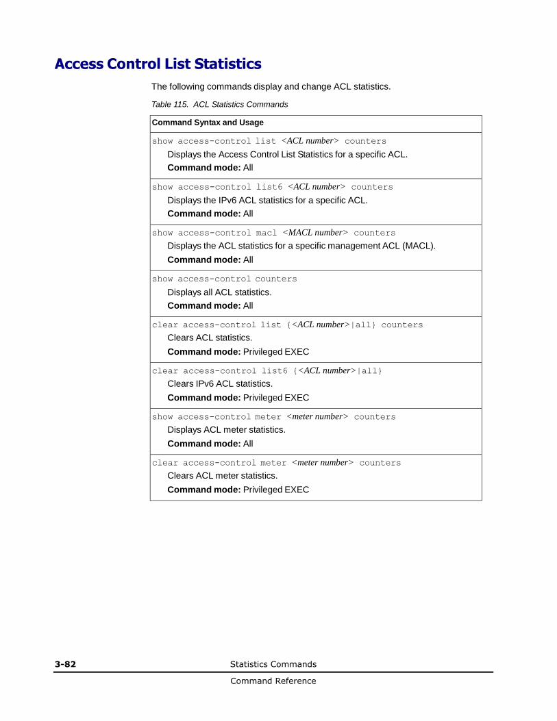
3-82 Statistics Commands
Command Reference
Access Control List Statistics
The following commands display and change ACL statistics.
Table 115. ACL Statistics Commands
Command Syntax and Usage
show access-control list <ACL number> counters
Displays the Access Control List Statistics for a specific ACL.
Command mode: All
show access-control list6 <ACL number> counters
Displays the IPv6 ACL statistics for a specific ACL.
Command mode: All
show access-control macl <MACL number> counters
Displays the ACL statistics for a specific management ACL (MACL).
Command mode: All
show access-control counters
Displays all ACL statistics.
Command mode: All
clear access-control list {<ACL number>|all} counters
Clears ACL statistics.
Command mode: Privileged EXEC
clear access-control list6 {<ACL number>|all}
Clears IPv6 ACL statistics.
Command mode: Privileged EXEC
show access-control meter <meter number> counters
Displays ACL meter statistics.
Command mode: All
clear access-control meter <meter number> counters
Clears ACL meter statistics.
Command mode: Privileged EXEC
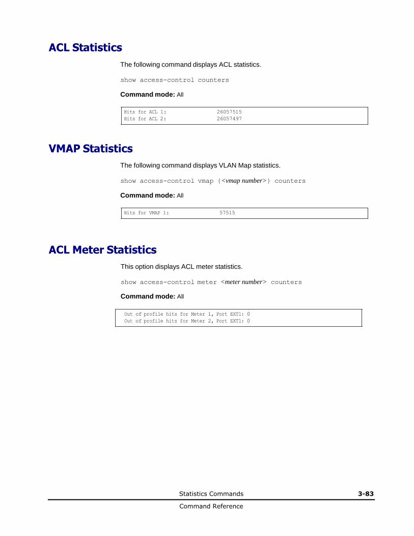
Statistics Commands 3-83
Command Reference
ACL Statistics
The following command displays ACL statistics.
show access-control counters
Command mode: All
Hits for ACL 1: 26057515
Hits for ACL 2: 26057497
VMAP Statistics
The following command displays VLAN Map statistics.
show access-control vmap {<vmap number>} counters
Command mode: All
Hits for VMAP 1: 57515
ACL Meter Statistics
This option displays ACL meter statistics.
show access-control meter <meter number> counters
Command mode: All
Out of profile hits for Meter 1, Port EXT1: 0
Out of profile hits for Meter 2, Port EXT1: 0
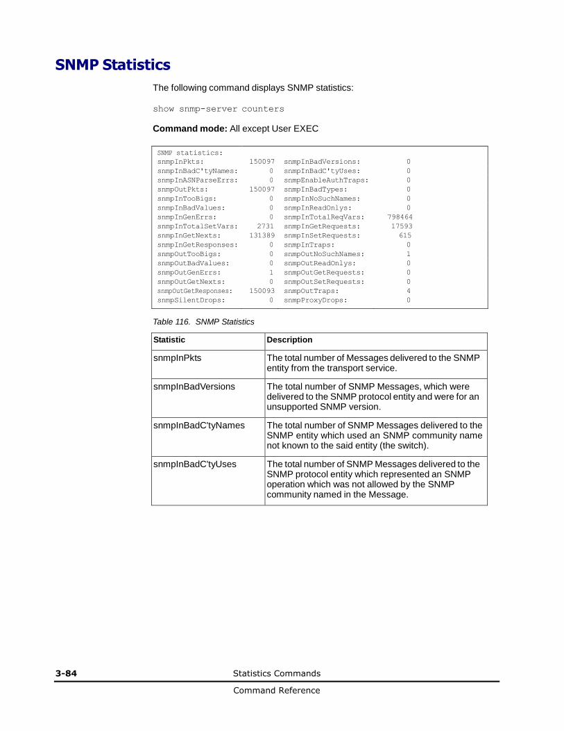
3-84 Statistics Commands
Command Reference
SNMP Statistics
The following command displays SNMP statistics:
show snmp-server counters
Command mode: All except User EXEC
SNMP statistics: snmpInPkts: 150097 snmpInBadVersions: 0
snmpInBadC'tyNames: 0 snmpInBadC'tyUses: 0
snmpInASNParseErrs: 0 snmpEnableAuthTraps: 0
snmpOutPkts: 150097 snmpInBadTypes: 0
snmpInTooBigs: 0 snmpInNoSuchNames: 0
snmpInBadValues: 0 snmpInReadOnlys: 0
snmpInGenErrs: 0 snmpInTotalReqVars: 798464
snmpInTotalSetVars: 2731 snmpInGetRequests: 17593
snmpInGetNexts: 131389 snmpInSetRequests: 615
snmpInGetResponses: 0 snmpInTraps: 0
snmpOutTooBigs: 0 snmpOutNoSuchNames: 1
snmpOutBadValues: 0 snmpOutReadOnlys: 0
snmpOutGenErrs: 1 snmpOutGetRequests: 0
snmpOutGetNexts: 0 snmpOutSetRequests: 0
snmpOutGetResponses: 150093 snmpOutTraps: 4
snmpSilentDrops: 0 snmpProxyDrops: 0
Table 116. SNMP Statistics
Statistic Description
snmpInPkts The total number of Messages delivered to the SNMP entity from the transport service.
snmpInBadVersions The total number of SNMP Messages, which were delivered to the SNMP protocol entity and were for an unsupported SNMP version.
snmpInBadC'tyNames The total number of SNMP Messages delivered to the SNMP entity which used an SNMP community name not known to the said entity (the switch).
snmpInBadC'tyUses The total number of SNMP Messages delivered to the SNMP protocol entity which represented an SNMP operation which was not allowed by the SNMP community named in the Message.
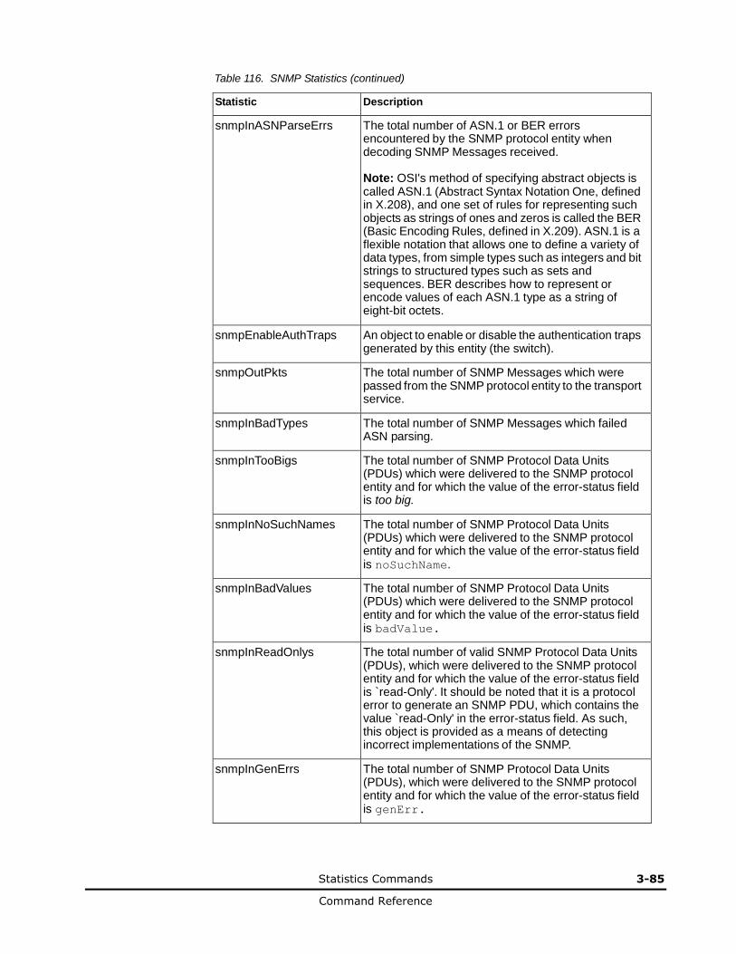
Statistics Commands 3-85
Command Reference
Table 116. SNMP Statistics (continued)
Statistic Description
snmpInASNParseErrs The total number of ASN.1 or BER errors encountered by the SNMP protocol entity when decoding SNMP Messages received. Note: OSI's method of specifying abstract objects is called ASN.1 (Abstract Syntax Notation One, defined in X.208), and one set of rules for representing such objects as strings of ones and zeros is called the BER (Basic Encoding Rules, defined in X.209). ASN.1 is a flexible notation that allows one to define a variety of data types, from simple types such as integers and bit strings to structured types such as sets and sequences. BER describes how to represent or encode values of each ASN.1 type as a string of eight-bit octets.
snmpEnableAuthTraps An object to enable or disable the authentication traps generated by this entity (the switch).
snmpOutPkts The total number of SNMP Messages which were passed from the SNMP protocol entity to the transport service.
snmpInBadTypes The total number of SNMP Messages which failed ASN parsing.
snmpInTooBigs The total number of SNMP Protocol Data Units (PDUs) which were delivered to the SNMP protocol entity and for which the value of the error-status field is too big.
snmpInNoSuchNames The total number of SNMP Protocol Data Units (PDUs) which were delivered to the SNMP protocol entity and for which the value of the error-status field is noSuchName.
snmpInBadValues The total number of SNMP Protocol Data Units (PDUs) which were delivered to the SNMP protocol entity and for which the value of the error-status field is badValue.
snmpInReadOnlys The total number of valid SNMP Protocol Data Units (PDUs), which were delivered to the SNMP protocol entity and for which the value of the error-status field is `read-Only'. It should be noted that it is a protocol error to generate an SNMP PDU, which contains the value `read-Only' in the error-status field. As such, this object is provided as a means of detecting incorrect implementations of the SNMP.
snmpInGenErrs The total number of SNMP Protocol Data Units (PDUs), which were delivered to the SNMP protocol entity and for which the value of the error-status field is genErr.
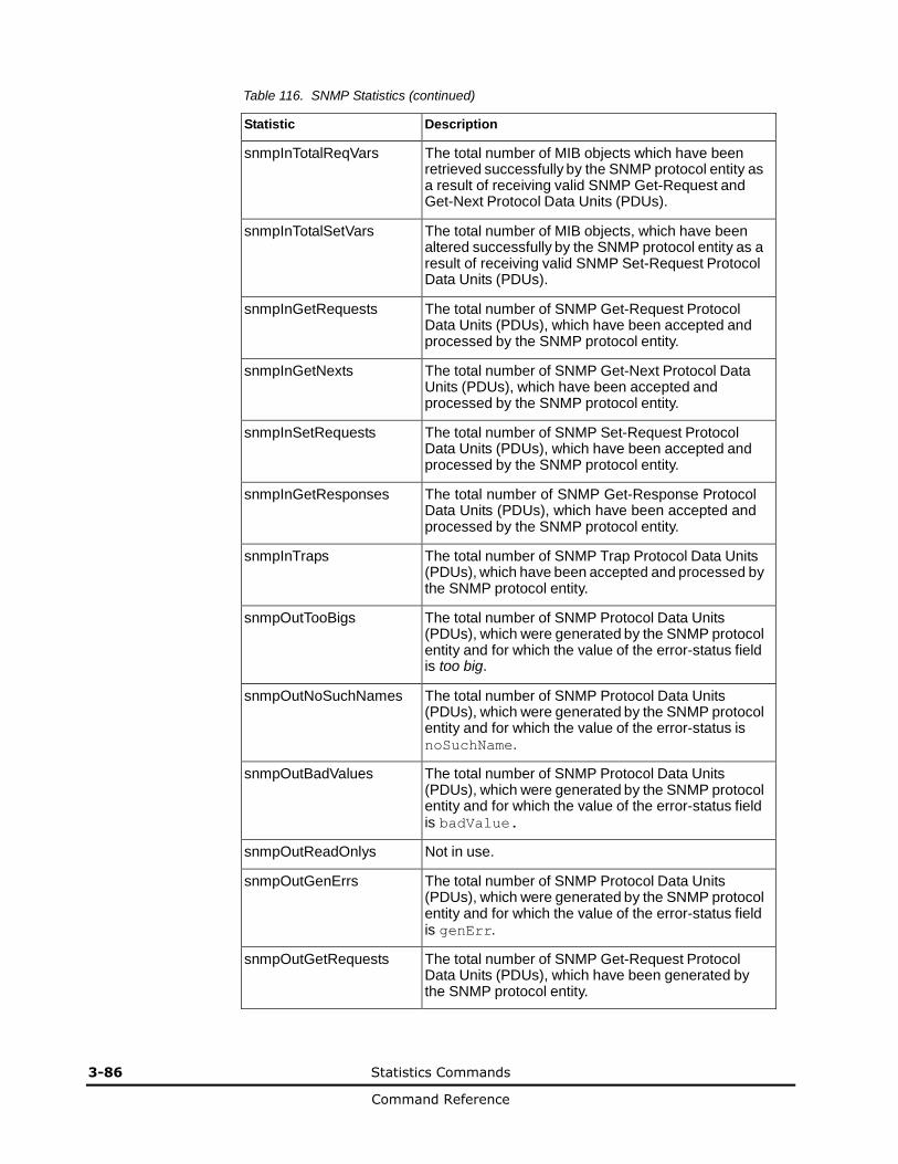
3-86 Statistics Commands
Command Reference
Table 116. SNMP Statistics (continued)
Statistic Description
snmpInTotalReqVars The total number of MIB objects which have been retrieved successfully by the SNMP protocol entity as a result of receiving valid SNMP Get-Request and Get-Next Protocol Data Units (PDUs).
snmpInTotalSetVars The total number of MIB objects, which have been altered successfully by the SNMP protocol entity as a result of receiving valid SNMP Set-Request Protocol Data Units (PDUs).
snmpInGetRequests The total number of SNMP Get-Request Protocol Data Units (PDUs), which have been accepted and processed by the SNMP protocol entity.
snmpInGetNexts The total number of SNMP Get-Next Protocol Data Units (PDUs), which have been accepted and processed by the SNMP protocol entity.
snmpInSetRequests The total number of SNMP Set-Request Protocol Data Units (PDUs), which have been accepted and processed by the SNMP protocol entity.
snmpInGetResponses The total number of SNMP Get-Response Protocol Data Units (PDUs), which have been accepted and processed by the SNMP protocol entity.
snmpInTraps The total number of SNMP Trap Protocol Data Units (PDUs), which have been accepted and processed by the SNMP protocol entity.
snmpOutTooBigs The total number of SNMP Protocol Data Units (PDUs), which were generated by the SNMP protocol entity and for which the value of the error-status field is too big.
snmpOutNoSuchNames The total number of SNMP Protocol Data Units (PDUs), which were generated by the SNMP protocol entity and for which the value of the error-status is noSuchName.
snmpOutBadValues The total number of SNMP Protocol Data Units (PDUs), which were generated by the SNMP protocol entity and for which the value of the error-status field is badValue.
snmpOutReadOnlys Not in use.
snmpOutGenErrs The total number of SNMP Protocol Data Units (PDUs), which were generated by the SNMP protocol entity and for which the value of the error-status field is genErr.
snmpOutGetRequests The total number of SNMP Get-Request Protocol Data Units (PDUs), which have been generated by the SNMP protocol entity.

Statistics Commands 3-87
Command Reference
Table 116. SNMP Statistics (continued)
Statistic Description
snmpOutGetNexts The total number of SNMP Get-Next Protocol Data Units (PDUs), which have been generated by the SNMP protocol entity.
snmpOutSetRequests The total number of SNMP Set-Request Protocol Data Units (PDUs), which have been generated by the SNMP protocol entity.
snmpOutGetResponses The total number of SNMP Get-Response Protocol Data Units (PDUs), which have been generated by the SNMP protocol entity.
snmpOutTraps The total number of SNMP Trap Protocol Data Units (PDUs), which have been generated by the SNMP protocol entity.
snmpSilentDrops The total number of GetRequest-PDUs, GetNextRequest-PDUs, GetBulkRequest-PDUs, SetRequest-PDUs, and InformRequest-PDUs delivered to the SNMPv2 entity which were silently dropped because the size of a reply containing an alternate Response-PDU with an empty variable bindings field was greater than either a local constraint or the maximum message size associated with the originator of the request.
snmpProxyDrops The total number of GetRequest-PDUs, GetNextRequest-PDUs, GetBulkRequest-PDUs, SetRequest-PDUs, and InformRequest-PDUs delivered to the SNMP entity which were silently dropped because the transmission of the message to a proxy target failed in a manner such that no Response-PDU could be returned.

3-88 Statistics Commands
Command Reference
NTP Statistics
Networking OS uses NTP (Network Timing Protocol) version 3 to synchronize the switch’s internal clock with an atomic time calibrated NTP server. With NTP enabled, the switch can accurately update its internal clock to be consistent with other devices on the network and generates accurate syslogs.
The following command displays NTP statistics:
show ntp counters
Command mode: All
NTP statistics:
Primary Server:
Requests Sent: 17
Responses Received: 17
Updates: 1
Secondary Server:
Requests Sent: 0
Responses Received: 0
Updates: 0
Last update based on response from primary/secondary server.
Last update time: 18:04:16 Tue Jul 13, 2010
Current system time: 18:55:49 Tue Jul 13, 2010
Table 117. NTP Statistics
Field Description
Primary Server • Requests Sent: The total number of NTP requests the switch sent to the primary NTP server to synchronize time.
• Responses Received: The total number of NTP responses received from the primary NTP server.
• Updates: The total number of times the switch updated its time based on the NTP responses received from the primary NTP server.
Secondary Server
• Requests Sent: The total number of NTP requests the switch sent to the secondary NTP server to synchronize time.
• Responses Received: The total number of NTP responses received from the secondary NTP server.
• Updates: The total number of times the switch updated its time based on the NTP responses received from the secondary NTP server.
Last update based on response from primary server
Last update of time on the switch based on either primary or secondary NTP response received.
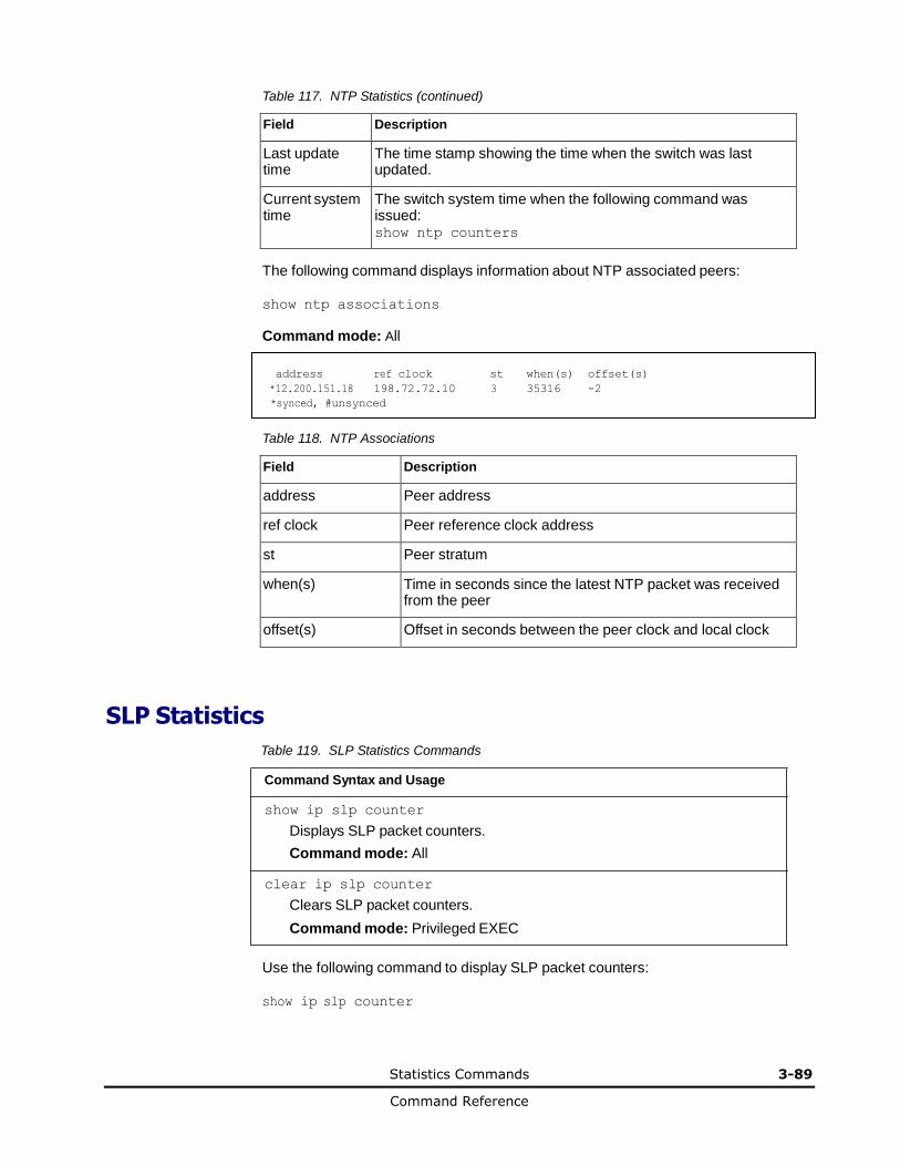
Statistics Commands 3-89
Command Reference
Table 117. NTP Statistics (continued)
Field Description
Last update time
The time stamp showing the time when the switch was last updated.
Current system time
The switch system time when the following command was issued: show ntp counters
The following command displays information about NTP associated peers:
show ntp associations
Command mode: All
address ref clock st when(s) offset(s)
*12.200.151.18 198.72.72.10 3 35316 -2
*synced, #unsynced
Table 118. NTP Associations
Field Description
address Peer address
ref clock Peer reference clock address
st Peer stratum
when(s) Time in seconds since the latest NTP packet was received from the peer
offset(s) Offset in seconds between the peer clock and local clock
SLP Statistics
Table 119. SLP Statistics Commands
Command Syntax and Usage
show ip slp counter
Displays SLP packet counters.
Command mode: All
clear ip slp counter
Clears SLP packet counters.
Command mode: Privileged EXEC
Use the following command to display SLP packet counters:
show ip slp counter
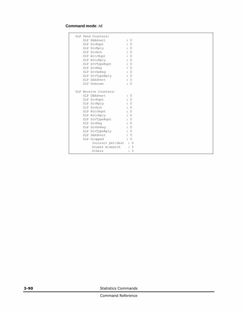
3-90 Statistics Commands
Command Reference
Command mode: All
SLP Send Counters:
SLP DAAdvert : 0
SLP SrvRqst : 0
SLP SrvRply : 0
SLP SrvAck : 0
SLP AttrRqst : 0
SLP AttrRply : 0
SLP SrvTypeRqst : 0
SLP SrvReg : 0
SLP SrvDeReg : 0
SLP SrvTypeRply : 0
SLP SAAdvert : 0
SLP Unknown : 0
SLP Receive Counters:
SLP DAAdvert : 0
SLP SrvRqst : 0
SLP SrvRply : 0
SLP SrvAck : 0
SLP AttrRqst : 0
SLP AttrRply : 0
SLP SrvTypeRqst : 0
SLP SrvReg : 0
SLP SrvDeReg : 0
SLP SrvTypeRply : 0
SLP SAAdvert : 0
SLP Dropped : 0
Incorect pkt/dest : 0
Scopes mismatch : 0
Others : 0

Statistics Commands 3-91
Command Reference
Statistics Dump
The following command dumps switch statistics:
show counters
Use the dump command to dump all switch statistics (40K or more, depending on your
configuration). This data can be used to tune or debug switch performance. If you want to capture dump data to a file, set your communication software on your workstation to capture session data prior to issuing the dump command.

4
Configuration Commands 4-1
Command Reference
Configuration Commands
This chapter discusses how to use the Command Line Interface (CLI) for
making, viewing, and saving switch configuration changes.
Configuration Commands
Viewing and Saving Changes
System Configuration
System Access Configuration
Port Configuration
Quality of Service Configuration
Access Control Configuration
Port Mirroring
Layer 2 Configuration
Layer 3 Configuration
Remote Monitoring Configuration
Virtualization Configuration
Switch Partition (SPAR) Configuration
Service Location Protocol Configuration
Configuration Dump
Saving the Active Switch Configuration
Restoring the Active Switch Configuration
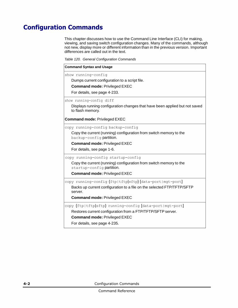
4-2 Configuration Commands
Command Reference
Configuration Commands
This chapter discusses how to use the Command Line Interface (CLI) for making, viewing, and saving switch configuration changes. Many of the commands, although not new, display more or different information than in the previous version. Important differences are called out in the text.
Table 120. General Configuration Commands
Command Syntax and Usage
show running-config
Dumps current configuration to a script file.
Command mode: Privileged EXEC
For details, see page 4-233.
show running-config diff
Displays running configuration changes that have been applied but not saved to flash memory.
Command mode: Privileged EXEC
copy running-config backup-config
Copy the current (running) configuration from switch memory to the
backup-config partition.
Command mode: Privileged EXEC
For details, see page 1-6.
copy running-config startup-config
Copy the current (running) configuration from switch memory to the startup-config partition.
Command mode: Privileged EXEC
copy running-config {ftp|tftp|sftp} [data-port|mgt-port]
Backs up current configuration to a file on the selected FTP/TFTP/SFTP server.
Command mode: Privileged EXEC
copy {ftp|tftp|sftp} running-config [data-port|mgt-port]
Restores current configuration from a FTP/TFTP/SFTP server.
Command mode: Privileged EXEC
For details, see page 4-235.
Configuration Commands 4-3
Command Reference
Viewing and Saving Changes
As you use the configuration commands to set switch parameters, the changes you make take effect immediately. You do not need to apply them. Configuration changes are lost the next time the switch boots, unless you save the changes.
You can view all running configuration changes that have been applied but not saved to flash memory using the show running-config diff command in Privileged EXEC mode.
Note: Some operations can override the settings of the Configuration commands. Therefore, settings you view using the Configuration commands (for example, port status) might differ from run-time information that you view using the Information commands. The Information commands display current run-time information of switch parameters.
Saving the Configuration
You must save configuration settings to flash memory, so 1/10Gb LAN Switch Module reloads the settings after a reset.
Note: If you do not save the changes, they will be lost the next time the system is rebooted.
To save the new configuration, enter the following command:
Router# copy running-config startup-config
When you save configuration changes, the changes are saved to the active configuration block. For instructions on selecting the configuration to run at the next system reset, see “Selecting a Configuration Block” on page 6-8.

4-4 Configuration Commands
Command Reference
System Configuration
These commands provide configuration of switch management parameters such as user and administrator privilege mode passwords, Web-based management settings, and management access lists.
Table 121. System Configuration Commands
Command Syntax and Usage
system date <yyyy> <mm> <dd>
Prompts the user for the system date. The date retains its value when the switch is reset. Command mode: Global configuration
system time <hh>:<mm>:<ss>
Configures the system time using a 24-hour clock format. The time retains its value when the switch is reset. Command mode: Global configuration
system timezone
Configures the time zone where the switch resides. You are prompted to select your location (continent, country, region) by the timezone wizard. Once a region is selected, the switch updates the time to reflect local changes to Daylight Saving Time, etc. Command mode: Global configuration
[no] system daylight
Disables or enables daylight saving time in the system clock. When enabled, the switch will add an extra hour to the system clock so that it is consistent with the local clock. By default, this option is disabled. Command mode: Global configuration
terminal-length <0-300>
Configures the number of lines per screen displayed in the CLI for the current session. A value of 0 disables paging. By default, it is set to the corresponding
line vty length or line console length value in effect at login.
Command mode: All
line console length <0-300>
Configures the number of lines per screen displayed in the CLI by default for console sessions. Setting it to 0 disables paging. The default value is 28. Command mode: Global configuration
no line console
Sets line console length to the default value of 28.
Command mode: Global configuration
line vty length <0-300>
Sets the default number of lines per screen displayed for Telnet and SSH sessions. A value of 0 disables paging. The default value is 28. Command mode: Global configuration
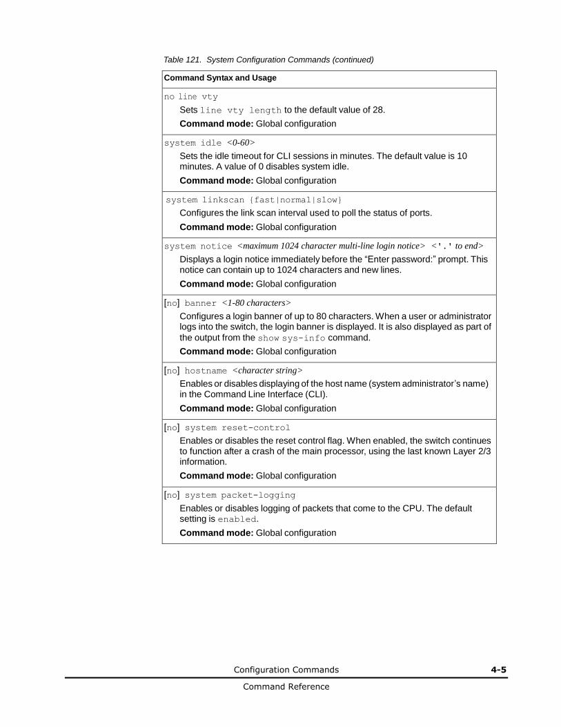
Configuration Commands 4-5
Command Reference
Table 121. System Configuration Commands (continued)
Command Syntax and Usage
no line vty
Sets line vty length to the default value of 28.
Command mode: Global configuration
system idle <0-60>
Sets the idle timeout for CLI sessions in minutes. The default value is 10 minutes. A value of 0 disables system idle.
Command mode: Global configuration
system linkscan {fast|normal|slow}
Configures the link scan interval used to poll the status of ports.
Command mode: Global configuration
system notice <maximum 1024 character multi-line login notice> <'.' to end>
Displays a login notice immediately before the “Enter password:” prompt. This notice can contain up to 1024 characters and new lines.
Command mode: Global configuration
[no] banner <1-80 characters>
Configures a login banner of up to 80 characters. When a user or administrator logs into the switch, the login banner is displayed. It is also displayed as part of
the output from the show sys-info command.
Command mode: Global configuration
[no] hostname <character string>
Enables or disables displaying of the host name (system administrator’s name) in the Command Line Interface (CLI).
Command mode: Global configuration
[no] system reset-control
Enables or disables the reset control flag. When enabled, the switch continues to function after a crash of the main processor, using the last known Layer 2/3 information.
Command mode: Global configuration
[no] system packet-logging
Enables or disables logging of packets that come to the CPU. The default setting is enabled.
Command mode: Global configuration

4-6 Configuration Commands
Command Reference
Table 121. System Configuration Commands (continued)
Command Syntax and Usage
[no] boot strict enable
Enables or disables switch operation in security strict mode. When enabled, the authentication and privacy protocols and algorithms of the device are compliant with NIST SP-800-131A, with non-compliant protocols and algorithms disabled.
Setting will be applied and device will be reset to default factory configuration after reboot.
The default setting is disabled.
Command mode: Global configuration
show boot strict
Displays the current security strict mode status.
Command mode: Global configuration
show system
Displays the current system parameters.
Command mode: All
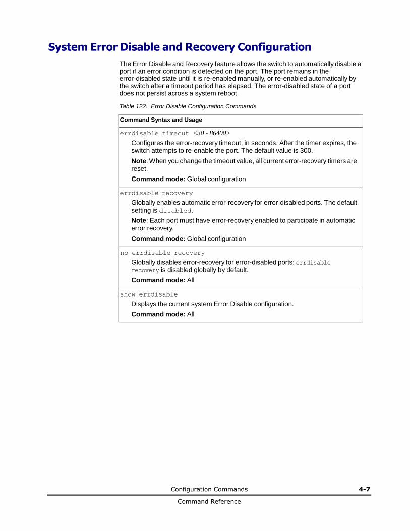
Configuration Commands 4-7
Command Reference
System Error Disable and Recovery Configuration
The Error Disable and Recovery feature allows the switch to automatically disable a port if an error condition is detected on the port. The port remains in the error-disabled state until it is re-enabled manually, or re-enabled automatically by the switch after a timeout period has elapsed. The error-disabled state of a port does not persist across a system reboot.
Table 122. Error Disable Configuration Commands
Command Syntax and Usage
errdisable timeout <30 - 86400>
Configures the error-recovery timeout, in seconds. After the timer expires, the switch attempts to re-enable the port. The default value is 300.
Note: When you change the timeout value, all current error-recovery timers are reset.
Command mode: Global configuration
errdisable recovery
Globally enables automatic error-recovery for error-disabled ports. The default
setting is disabled.
Note: Each port must have error-recovery enabled to participate in automatic error recovery.
Command mode: Global configuration
no errdisable recovery
Globally disables error-recovery for error-disabled ports; errdisable recovery is disabled globally by default.
Command mode: All
show errdisable
Displays the current system Error Disable configuration.
Command mode: All

4-8 Configuration Commands
Command Reference
System Host Log Configuration Table 123. Host Log Configuration Commands
Command Syntax and Usage
[no] logging host <1-2> address <IP address> [data-port|mgt-port]
Sets the IPv4 address of the first or second syslog host.
Command mode: Global configuration
[no] logging host <1-2> address6 <IP address> [data-port|mgt-port]
Sets the IPv6 address of the first or second syslog host.
Command mode: Global configuration
logging host <1-2> severity <0-7>
This option sets the severity level of the first or second syslog host displayed. The default is 7, which means log all severity levels.
Command mode: Global configuration
logging host <1-2> facility <0-7>
This option sets the facility level of the first or second syslog host displayed. The default is 0.
Command mode: Global configuration
logging source-interface <1-5>
Sets the loopback interface number for syslogs.
Command mode: Global configuration
logging console
Enables delivering syslog messages to the console. It is enabled by default.
Command mode: Global configuration
no logging console
Disables delivering syslog messages to the console. When necessary, disabling console ensures the switch is not affected by syslog messages. It is enabled by default.
Command mode: Global configuration
[no] logging synchronous [level <0-7> | all]
Enables or disables synchronous logging messages. When enabled, logging messages are displayed asynchronously.
The level parameter sets the message severity level. Messages with a severity level equal to or higher than this value are displayed asynchronously. Low numbers indicate greater severity. All displays all messages
asynchronously, regardless the severity level. The default setting is 2.
Command mode: Global configuration
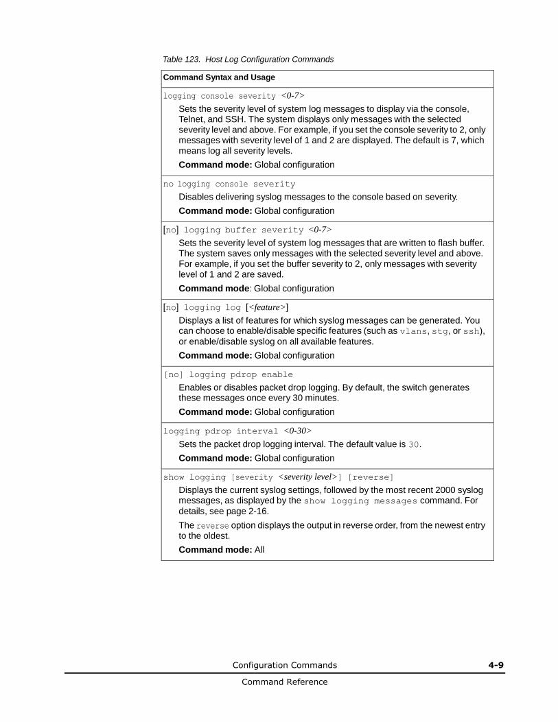
Configuration Commands 4-9
Command Reference
Table 123. Host Log Configuration Commands
Command Syntax and Usage
logging console severity <0-7>
Sets the severity level of system log messages to display via the console, Telnet, and SSH. The system displays only messages with the selected severity level and above. For example, if you set the console severity to 2, only messages with severity level of 1 and 2 are displayed. The default is 7, which means log all severity levels.
Command mode: Global configuration
no logging console severity
Disables delivering syslog messages to the console based on severity.
Command mode: Global configuration
[no] logging buffer severity <0-7>
Sets the severity level of system log messages that are written to flash buffer. The system saves only messages with the selected severity level and above. For example, if you set the buffer severity to 2, only messages with severity level of 1 and 2 are saved.
Command mode: Global configuration
[no] logging log [<feature>]
Displays a list of features for which syslog messages can be generated. You can choose to enable/disable specific features (such as vlans, stg, or ssh),
or enable/disable syslog on all available features.
Command mode: Global configuration
[no] logging pdrop enable
Enables or disables packet drop logging. By default, the switch generates these messages once every 30 minutes.
Command mode: Global configuration
logging pdrop interval <0-30>
Sets the packet drop logging interval. The default value is 30.
Command mode: Global configuration
show logging [severity <severity level>] [reverse]
Displays the current syslog settings, followed by the most recent 2000 syslog messages, as displayed by the show logging messages command. For
details, see page 2-16.
The reverse option displays the output in reverse order, from the newest entry to the oldest.
Command mode: All

4-10 Configuration Commands
Command Reference
SSH Server Configuration
For 1/10Gb LAN Switch Module, these commands enable Secure Shell access from
any SSH client.
Table 124. SSH Server Configuration Commands
Command Syntax and Usage
ssh scp-password
Set the administration password for SCP access.
Command mode: Global configuration
ssh generate-host-key
Generate the RSA host key.
Command mode: Global configuration
ssh port <TCP port number>
Sets the SSH server port number.
Command mode: Global configuration
ssh scp-enable
Enables the SCP apply and save.
Command mode: Global configuration
no ssh scp-enable
Disables the SCP apply and save.
Command mode: Global configuration
ssh enable
Enables the SSH server.
Command mode: Global configuration
no ssh enable
Disables the SSH server.
Command mode: Global configuration
show ssh
Displays the current SSH server configuration.
Command mode: All
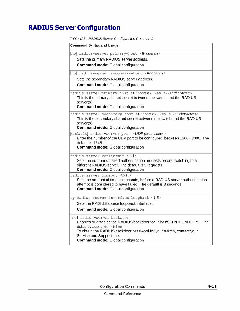
Configuration Commands 4-11
Command Reference
RADIUS Server Configuration
Table 125. RADIUS Server Configuration Commands
Command Syntax and Usage
[no] radius-server primary-host <IP address>
Sets the primary RADIUS server address.
Command mode: Global configuration
[no] radius-server secondary-host <IP address>
Sets the secondary RADIUS server address.
Command mode: Global configuration
radius-server primary-host <IP address> key <1-32 characters>
This is the primary shared secret between the switch and the RADIUS server(s). Command mode: Global configuration
radius-server secondary-host <IP address> key <1-32 characters>
This is the secondary shared secret between the switch and the RADIUS server(s). Command mode: Global configuration
[default] radius-server port <UDP port number>
Enter the number of the UDP port to be configured, between 1500 - 3000. The default is 1645. Command mode: Global configuration
radius-server retransmit <1-3>
Sets the number of failed authentication requests before switching to a different RADIUS server. The default is 3 requests. Command mode: Global configuration
radius-server timeout <1-10>
Sets the amount of time, in seconds, before a RADIUS server authentication attempt is considered to have failed. The default is 3 seconds. Command mode: Global configuration
ip radius source-interface loopback <1-5>
Sets the RADIUS source loopback interface.
Command mode: Global configuration
[no] radius-server backdoor
Enables or disables the RADIUS backdoor for Telnet/SSH/HTTP/HTTPS. The default value is disabled. To obtain the RADIUS backdoor password for your switch, contact your Service and Support line. Command mode: Global configuration
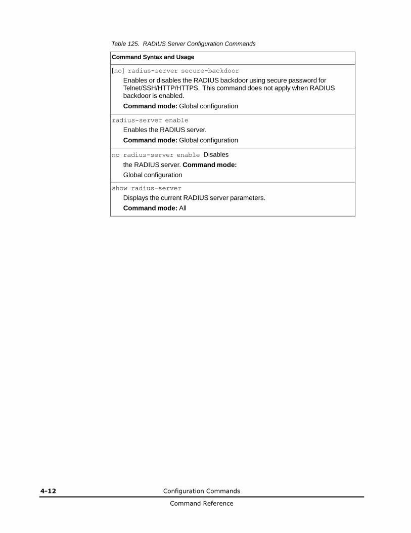
4-12 Configuration Commands
Command Reference
Table 125. RADIUS Server Configuration Commands
Command Syntax and Usage
[no] radius-server secure-backdoor
Enables or disables the RADIUS backdoor using secure password for Telnet/SSH/HTTP/HTTPS. This command does not apply when RADIUS backdoor is enabled.
Command mode: Global configuration
radius-server enable
Enables the RADIUS server.
Command mode: Global configuration
no radius-server enable Disables
the RADIUS server. Command mode:
Global configuration
show radius-server
Displays the current RADIUS server parameters.
Command mode: All

Configuration Commands 4-13
Command Reference
TACACS+ Server Configuration
TACACS (Terminal Access Controller Access Control system) is an authentication protocol that allows a remote access server to forward a user's logon password to an authentication server to determine whether access can be allowed to a given system. TACACS is not an encryption protocol, and therefore less secure than TACACS+ and Remote Authentication Dial-In User Service (RADIUS) protocols. Both TACACS and TACACS+ are described in RFC 1492.
TACACS+ protocol is more reliable than RADIUS, as TACACS+ uses the Transmission Control Protocol (TCP) whereas RADIUS uses the User Datagram Protocol (UDP). Also, RADIUS combines authentication and authorization in a user profile, whereas TACACS+ separates the two operations.
TACACS+ offers the following advantages over RADIUS as the authentication device:
• TACACS+ is TCP-based, so it facilitates connection-oriented traffic.
• It supports full-packet encryption, as opposed to password-only in authentication requests.
• It supports de-coupled authentication, authorization, and accounting.
Table 126. TACACS+ Server Configuration Commands
Command Syntax and Usage
[no] tacacs primary-host <IP address>
Defines the primary TACACS+ server address.
Command mode: Global configuration
[no] tacacs secondary-host <IP address>
Defines the secondary TACACS+ server address.
Command mode: Global configuration
[no] tacacs primary-host <IP address> key <1-32 characters>
This is the primary shared secret between the switch and the TACACS+ server(s).
Command mode: Global configuration
[no] tacacs secondary-host <IP address> key <1-32 characters>
This is the secondary shared secret between the switch and the TACACS+ server(s).
Command mode: Global configuration
[default] tacacs port <TCP port number>
Enter the number of the TCP port to be configured, between 1 and 65000. The default is 49.
Command mode: Global configuration
tacacs retransmit <1-3>
Sets the number of failed authentication requests before switching to a different TACACS+ server. The default is 3 requests.
Command mode: Global configuration

4-14 Configuration Commands
Command Reference
Table 126. TACACS+ Server Configuration Commands (continued)
Command Syntax and Usage
tacacs attempts <1-10>
Sets the number of failed login attempts before disconnecting the user. The default is 2 attempts. Command mode: Global configuration
tacacs timeout <4-15>
Sets the amount of time, in seconds, before a TACACS+ server authentication attempt is considered to have failed. The default is 5 seconds. Command mode: Global configuration
ip tacacs source-interface loopback <1-5>
Sets the TACACS+ source loopback interface.
Command mode: Global configuration
[no] tacacs user-mapping {<0-15> user|oper|admin}
Maps a TACACS+ authorization level to a switch user level. Enter a TACACS+ authorization level (0-15), followed by the corresponding switch user level. Command mode: Global configuration
[no] tacacs backdoor
Enables or disables the TACACS+ back door for Telnet, SSH/SCP, or HTTP/HTTPS. Enabling this feature allows you to bypass the TACACS+ servers. It is recommended that you use Secure Backdoor to ensure the switch is secured, because Secure Backdoor disallows access through the back door when the TACACS+ servers are responding.
The default setting is disabled.
To obtain the TACACS+ backdoor password for your 1/10Gb LAN Switch Module, contact your Service and Support line. Command mode: Global configuration
[no] tacacs secure-backdoor
Enables or disables TACACS+ secure back door access through Telnet, SSH/SCP, or HTTP/HTTPS only when the TACACS+ servers are not responding. This feature is recommended to permit access to the switch when the TACACS+ servers become unresponsive. If no back door is enabled, the only way to gain access when TACACS+ servers are unresponsive is to use the back door via the console port.
The default is disabled.
Command mode: Global configuration
[no] tacacs privilege-mapping
Enables or disables TACACS+ privilege-level mapping.
The default value is disabled.
Command mode: Global configuration
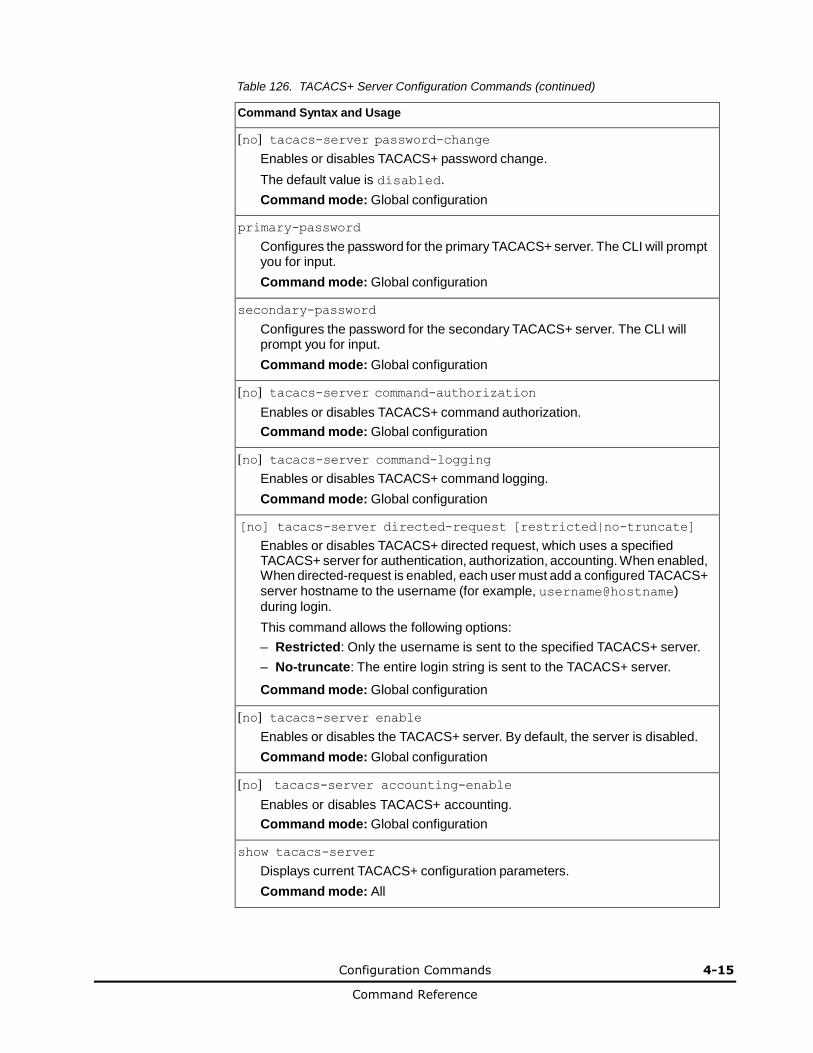
Configuration Commands 4-15
Command Reference
Table 126. TACACS+ Server Configuration Commands (continued)
Command Syntax and Usage
[no] tacacs-server password-change
Enables or disables TACACS+ password change.
The default value is disabled.
Command mode: Global configuration
primary-password
Configures the password for the primary TACACS+ server. The CLI will prompt you for input.
Command mode: Global configuration
secondary-password
Configures the password for the secondary TACACS+ server. The CLI will prompt you for input.
Command mode: Global configuration
[no] tacacs-server command-authorization
Enables or disables TACACS+ command authorization.
Command mode: Global configuration
[no] tacacs-server command-logging
Enables or disables TACACS+ command logging.
Command mode: Global configuration
[no] tacacs-server directed-request [restricted|no-truncate]
Enables or disables TACACS+ directed request, which uses a specified TACACS+ server for authentication, authorization, accounting. When enabled, When directed-request is enabled, each user must add a configured TACACS+ server hostname to the username (for example, username@hostname)
during login.
This command allows the following options:
– Restricted: Only the username is sent to the specified TACACS+ server.
– No-truncate: The entire login string is sent to the TACACS+ server.
Command mode: Global configuration
[no] tacacs-server enable
Enables or disables the TACACS+ server. By default, the server is disabled.
Command mode: Global configuration
[no] tacacs-server accounting-enable
Enables or disables TACACS+ accounting.
Command mode: Global configuration
show tacacs-server
Displays current TACACS+ configuration parameters.
Command mode: All
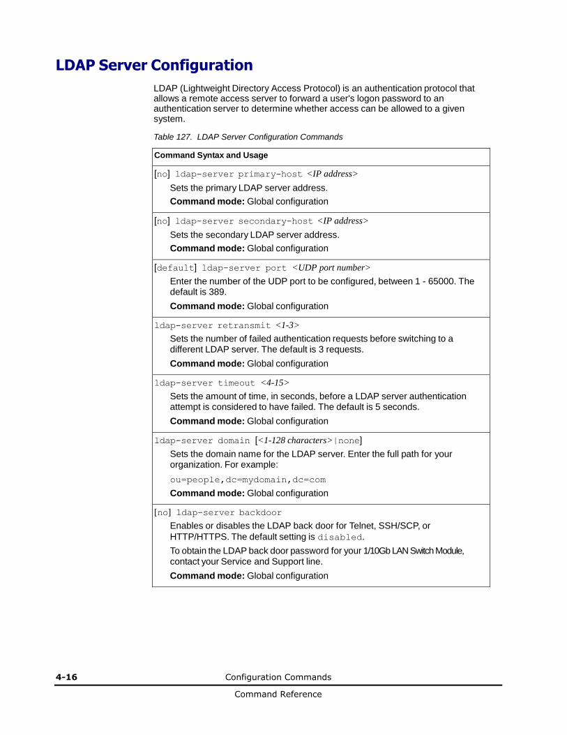
4-16 Configuration Commands
Command Reference
LDAP Server Configuration
LDAP (Lightweight Directory Access Protocol) is an authentication protocol that allows a remote access server to forward a user's logon password to an authentication server to determine whether access can be allowed to a given system.
Table 127. LDAP Server Configuration Commands
Command Syntax and Usage
[no] ldap-server primary-host <IP address>
Sets the primary LDAP server address.
Command mode: Global configuration
[no] ldap-server secondary-host <IP address>
Sets the secondary LDAP server address.
Command mode: Global configuration
[default] ldap-server port <UDP port number>
Enter the number of the UDP port to be configured, between 1 - 65000. The default is 389.
Command mode: Global configuration
ldap-server retransmit <1-3>
Sets the number of failed authentication requests before switching to a different LDAP server. The default is 3 requests.
Command mode: Global configuration
ldap-server timeout <4-15>
Sets the amount of time, in seconds, before a LDAP server authentication attempt is considered to have failed. The default is 5 seconds.
Command mode: Global configuration
ldap-server domain [<1-128 characters>|none]
Sets the domain name for the LDAP server. Enter the full path for your organization. For example:
ou=people,dc=mydomain,dc=com
Command mode: Global configuration
[no] ldap-server backdoor
Enables or disables the LDAP back door for Telnet, SSH/SCP, or
HTTP/HTTPS. The default setting is disabled.
To obtain the LDAP back door password for your 1/10Gb LAN Switch Module, contact your Service and Support line.
Command mode: Global configuration
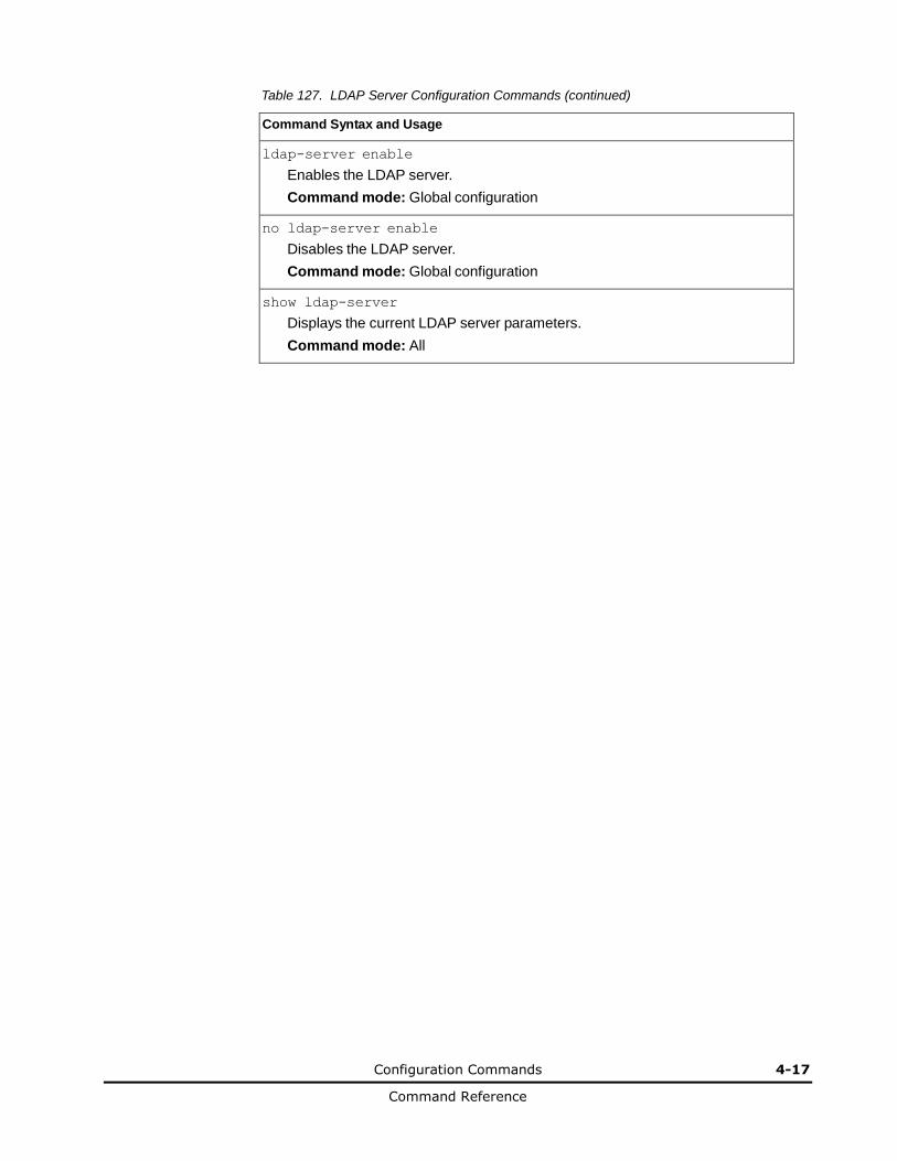
Configuration Commands 4-17
Command Reference
Table 127. LDAP Server Configuration Commands (continued)
Command Syntax and Usage
ldap-server enable
Enables the LDAP server.
Command mode: Global configuration
no ldap-server enable
Disables the LDAP server.
Command mode: Global configuration
show ldap-server
Displays the current LDAP server parameters.
Command mode: All
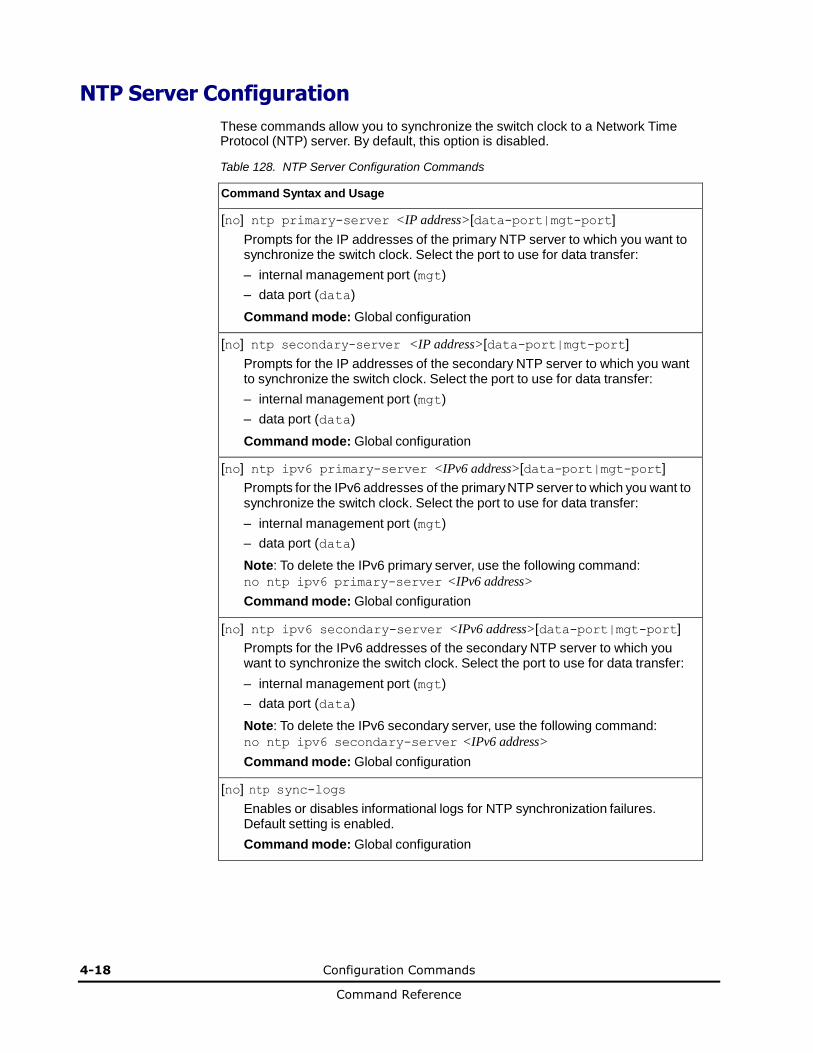
4-18 Configuration Commands
Command Reference
NTP Server Configuration
These commands allow you to synchronize the switch clock to a Network Time Protocol (NTP) server. By default, this option is disabled.
Table 128. NTP Server Configuration Commands
Command Syntax and Usage
[no] ntp primary-server <IP address>[data-port|mgt-port]
Prompts for the IP addresses of the primary NTP server to which you want to synchronize the switch clock. Select the port to use for data transfer:
– internal management port (mgt)
– data port (data)
Command mode: Global configuration
[no] ntp secondary-server <IP address>[data-port|mgt-port]
Prompts for the IP addresses of the secondary NTP server to which you want to synchronize the switch clock. Select the port to use for data transfer:
– internal management port (mgt)
– data port (data)
Command mode: Global configuration
[no] ntp ipv6 primary-server <IPv6 address>[data-port|mgt-port]
Prompts for the IPv6 addresses of the primary NTP server to which you want to synchronize the switch clock. Select the port to use for data transfer:
– internal management port (mgt)
– data port (data)
Note: To delete the IPv6 primary server, use the following command:
no ntp ipv6 primary-server <IPv6 address>
Command mode: Global configuration
[no] ntp ipv6 secondary-server <IPv6 address>[data-port|mgt-port]
Prompts for the IPv6 addresses of the secondary NTP server to which you want to synchronize the switch clock. Select the port to use for data transfer:
– internal management port (mgt)
– data port (data)
Note: To delete the IPv6 secondary server, use the following command:
no ntp ipv6 secondary-server <IPv6 address>
Command mode: Global configuration
[no] ntp sync-logs
Enables or disables informational logs for NTP synchronization failures. Default setting is enabled.
Command mode: Global configuration
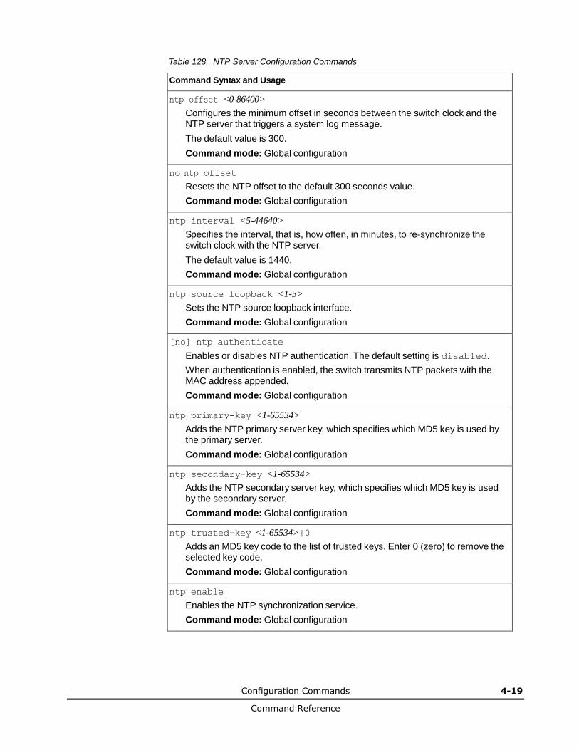
Configuration Commands 4-19
Command Reference
Table 128. NTP Server Configuration Commands
Command Syntax and Usage
ntp offset <0-86400>
Configures the minimum offset in seconds between the switch clock and the NTP server that triggers a system log message.
The default value is 300.
Command mode: Global configuration
no ntp offset
Resets the NTP offset to the default 300 seconds value.
Command mode: Global configuration
ntp interval <5-44640>
Specifies the interval, that is, how often, in minutes, to re-synchronize the switch clock with the NTP server.
The default value is 1440.
Command mode: Global configuration
ntp source loopback <1-5>
Sets the NTP source loopback interface.
Command mode: Global configuration
[no] ntp authenticate
Enables or disables NTP authentication. The default setting is disabled.
When authentication is enabled, the switch transmits NTP packets with the MAC address appended.
Command mode: Global configuration
ntp primary-key <1-65534>
Adds the NTP primary server key, which specifies which MD5 key is used by the primary server.
Command mode: Global configuration
ntp secondary-key <1-65534>
Adds the NTP secondary server key, which specifies which MD5 key is used by the secondary server.
Command mode: Global configuration
ntp trusted-key <1-65534>|0
Adds an MD5 key code to the list of trusted keys. Enter 0 (zero) to remove the selected key code.
Command mode: Global configuration
ntp enable
Enables the NTP synchronization service.
Command mode: Global configuration
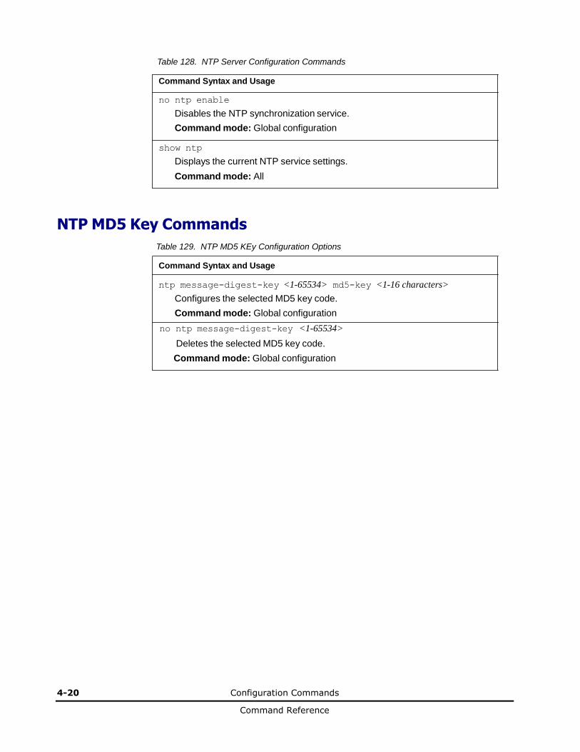
4-20 Configuration Commands
Command Reference
Table 128. NTP Server Configuration Commands
Command Syntax and Usage
no ntp enable
Disables the NTP synchronization service.
Command mode: Global configuration
show ntp
Displays the current NTP service settings.
Command mode: All
NTP MD5 Key Commands
Table 129. NTP MD5 KEy Configuration Options
Command Syntax and Usage
ntp message-digest-key <1-65534> md5-key <1-16 characters>
Configures the selected MD5 key code.
Command mode: Global configuration
no ntp message-digest-key <1-65534>
Deletes the selected MD5 key code.
Command mode: Global configuration

Configuration Commands 4-21
Command Reference
System SNMP Configuration
Networking OS supports SNMP-based network management. In SNMP model of network management, a management station (client/manager) accesses a set of variables known as MIBs (Management Information Base) provided by the managed device (agent). If you are running an SNMP network management station on your network, you can manage the switch using the following standard SNMP MIBs:
• MIB II (RFC 1213)
• Ethernet MIB (RFC 1643)
• Bridge MIB (RFC 1493)
An SNMP agent is a software process on the managed device that listens on UDP port 161 for SNMP messages. Each SNMP message sent to the agent contains a list of management objects to retrieve or to modify.
SNMP parameters that can be modified include:
• System name
• System location
• System contact
• Use of the SNMP system authentication trap function
• Read community string
• Write community string
• Trap community strings
Table 130. System SNMP Commands
Command Syntax and Usage
snmp-server name <1-64 characters>
Configures the name for the system. The name can have a maximum of 64 characters.
Command mode: Global configuration
snmp-server location <1-64 characters>
Configures the name of the system location. The location can have a maximum of 64 characters.
Command mode: Global configuration
snmp-server contact <1-64 characters>
Configures the name of the system contact. The contact can have a maximum of 64 characters.
Command mode: Global configuration
snmp-server read-community <1-32 characters>
Configures the SNMP read community string. The read community string controls SNMP “get” access to the switch. It can have a maximum of 32 characters. The default read community string is public.
Command mode: Global configuration
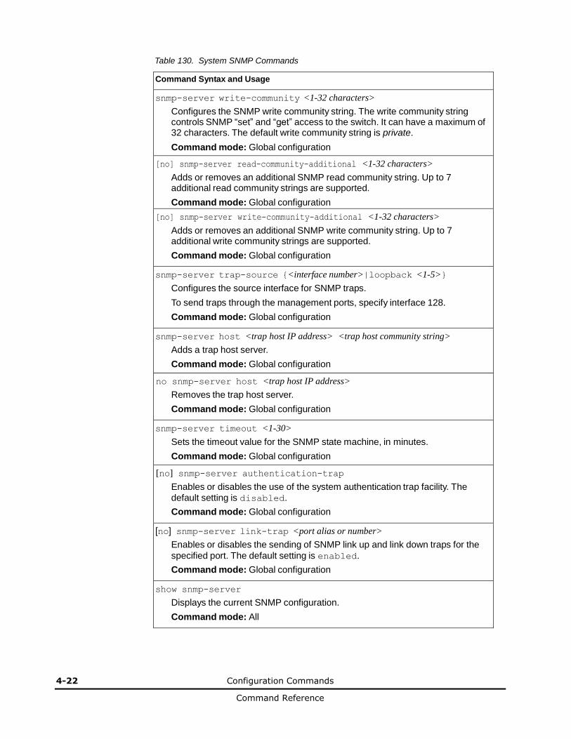
4-22 Configuration Commands
Command Reference
Table 130. System SNMP Commands
Command Syntax and Usage
snmp-server write-community <1-32 characters>
Configures the SNMP write community string. The write community string controls SNMP “set” and “get” access to the switch. It can have a maximum of 32 characters. The default write community string is private.
Command mode: Global configuration
[no] snmp-server read-community-additional <1-32 characters>
Adds or removes an additional SNMP read community string. Up to 7 additional read community strings are supported.
Command mode: Global configuration
[no] snmp-server write-community-additional <1-32 characters>
Adds or removes an additional SNMP write community string. Up to 7 additional write community strings are supported.
Command mode: Global configuration
snmp-server trap-source {<interface number>|loopback <1-5>}
Configures the source interface for SNMP traps.
To send traps through the management ports, specify interface 128.
Command mode: Global configuration
snmp-server host <trap host IP address> <trap host community string>
Adds a trap host server.
Command mode: Global configuration
no snmp-server host <trap host IP address>
Removes the trap host server.
Command mode: Global configuration
snmp-server timeout <1-30>
Sets the timeout value for the SNMP state machine, in minutes.
Command mode: Global configuration
[no] snmp-server authentication-trap
Enables or disables the use of the system authentication trap facility. The
default setting is disabled.
Command mode: Global configuration
[no] snmp-server link-trap <port alias or number>
Enables or disables the sending of SNMP link up and link down traps for the
specified port. The default setting is enabled.
Command mode: Global configuration
show snmp-server
Displays the current SNMP configuration.
Command mode: All
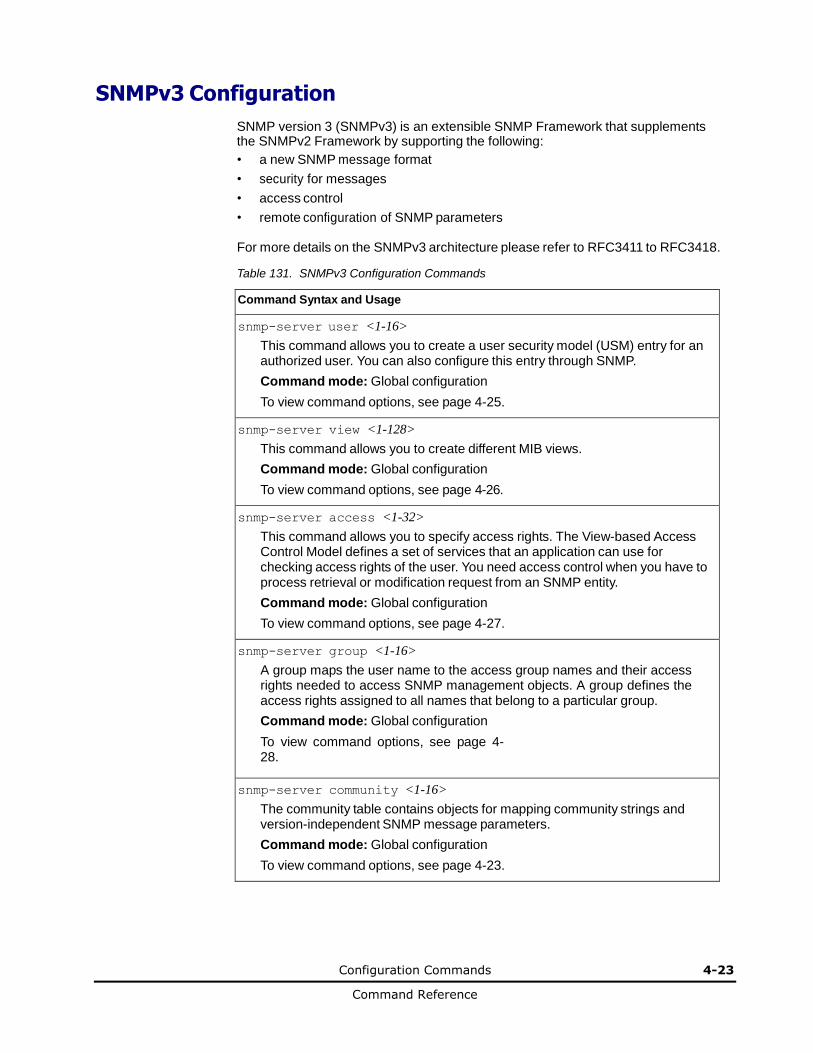
Configuration Commands 4-23
Command Reference
SNMPv3 Configuration
SNMP version 3 (SNMPv3) is an extensible SNMP Framework that supplements the SNMPv2 Framework by supporting the following:
• a new SNMP message format
• security for messages
• access control
• remote configuration of SNMP parameters
For more details on the SNMPv3 architecture please refer to RFC3411 to RFC3418.
Table 131. SNMPv3 Configuration Commands
Command Syntax and Usage
snmp-server user <1-16>
This command allows you to create a user security model (USM) entry for an authorized user. You can also configure this entry through SNMP.
Command mode: Global configuration
To view command options, see page 4-25.
snmp-server view <1-128>
This command allows you to create different MIB views.
Command mode: Global configuration
To view command options, see page 4-26.
snmp-server access <1-32>
This command allows you to specify access rights. The View-based Access Control Model defines a set of services that an application can use for checking access rights of the user. You need access control when you have to process retrieval or modification request from an SNMP entity.
Command mode: Global configuration
To view command options, see page 4-27.
snmp-server group <1-16>
A group maps the user name to the access group names and their access rights needed to access SNMP management objects. A group defines the access rights assigned to all names that belong to a particular group.
Command mode: Global configuration
To view command options, see page 4-28.
snmp-server community <1-16>
The community table contains objects for mapping community strings and version-independent SNMP message parameters.
Command mode: Global configuration
To view command options, see page 4-23.
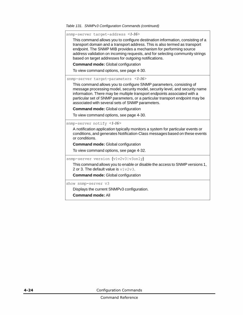
4-24 Configuration Commands
Command Reference
Table 131. SNMPv3 Configuration Commands (continued)
snmp-server target-address <1-16>
This command allows you to configure destination information, consisting of a transport domain and a transport address. This is also termed as transport endpoint. The SNMP MIB provides a mechanism for performing source address validation on incoming requests, and for selecting community strings based on target addresses for outgoing notifications.
Command mode: Global configuration
To view command options, see page 4-30.
snmp-server target-parameters <1-16>
This command allows you to configure SNMP parameters, consisting of message processing model, security model, security level, and security name information. There may be multiple transport endpoints associated with a particular set of SNMP parameters, or a particular transport endpoint may be associated with several sets of SNMP parameters.
Command mode: Global configuration
To view command options, see page 4-30.
snmp-server notify <1-16>
A notification application typically monitors a system for particular events or conditions, and generates Notification-Class messages based on these events or conditions.
Command mode: Global configuration
To view command options, see page 4-32.
snmp-server version {v1v2v3|v3only}
This command allows you to enable or disable the access to SNMP versions 1,
2 or 3. The default value is v1v2v3.
Command mode: Global configuration
show snmp-server v3
Displays the current SNMPv3 configuration.
Command mode: All

Configuration Commands 4-25
Command Reference
User Security Model Configuration
You can make use of a defined set of user identities using this Security Model. An SNMP engine must have the knowledge of applicable attributes of a user.
These commands help you create a user security model entry for an authorized user. You need to provide a security name to create the USM entry.
Table 132. User Security Model Configuration Commands
Command Syntax and Usage
snmp-server user <1-16> name <1-32 characters>
This command allows you to configure a string that represents the name of the user. This is the login name that you need in order to access the switch.
Command mode: Global configuration
snmp-server user <1-16> authentication-protocol {md5|sha|none} authentication-password <password value>
This command allows you to configure the authentication protocol and password.
The authentication protocol can be HMAC-MD5-96 or HMAC-SHA-96 for compatibility mode, HMAC-SHA-96 for security strict mode, or none. The
default algorithm is none.
MD5 authentication protocol is not available in security strict mode if you do not select SNMPv3 account backward compatibility.
When you configure an authentication algorithm, you must provide a password, otherwise you will get an error message during validation. This command allows you to create or change your password for authentication.
Command mode: Global configuration
snmp-server user <1-16> privacy-protocol {aes|des|none} privacy-password <password value>
This command allows you to configure the type of privacy protocol and the privacy password.
The privacy protocol protects messages from disclosure. The options are des
(CBC-DES Symmetric Encryption Protocol), aes (AES-128 Advanced
Encryption Standard Protocol) or none. If you specify des as the privacy protocol, then make sure that you have selected one of the authentication protocols (MD5 or HMAC-SHA-96). In security strict mode, if you do not select SNMPv3 account backward compatibility, make sure to disable des privacy
protocol. If you specify aes as the privacy protocol, make sure that you have
selected HMAC-SHA-256 authentication protocol. If you select none as the authentication protocol, you will get an error message.
You can create or change the privacy password.
Command mode: Global configuration

4-26 Configuration Commands
Command Reference
Table 132. User Security Model Configuration Commands
Command Syntax and Usage
no snmp-server user <1-16> Deletes
the USM user entries. Command
mode: Global configuration
show snmp-server v3 user <1-16>
Displays the USM user entries.
Command mode: All
SNMPv3 View Configuration
Note that the first five default vacmViewTreeFamily entries cannot be removed, and their names cannot be changed.
Table 133. SNMPv3 View Configuration Commands
Command Syntax and Usage
snmp-server view <1-128> name <1-32 characters>
This command defines the name for a family of view subtrees.
Command mode: Global configuration
snmp-server view <1-128> tree <1-64 characters>
This command defines MIB tree, which when combined with the corresponding mask defines a family of view subtrees.
Command mode: Global configuration
[no] snmp-server view <1-128> mask <1-32 characters>
This command defines the bit mask, which in combination with the corresponding tree defines a family of view subtrees.
Command mode: Global configuration
snmp-server view <1-128> type {included|excluded}
This command indicates whether the corresponding instances of vacmViewTreeFamilySubtree and vacmViewTreeFamilyMask define
a family of view subtrees, which is included in or excluded from the MIB view.
Command mode: Global configuration
no snmp-server view <1-128>
Deletes the vacmViewTreeFamily group entry.
Command mode: Global configuration
show snmp-server v3 view <1-128>
Displays the current vacmViewTreeFamily configuration.
Command mode: All
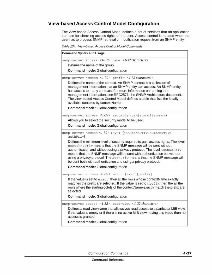
Configuration Commands 4-27
Command Reference
View-based Access Control Model Configuration
The view-based Access Control Model defines a set of services that an application can use for checking access rights of the user. Access control is needed when the user has to process SNMP retrieval or modification request from an SNMP entity.
Table 134. View-based Access Control Model Commands
Command Syntax and Usage
snmp-server access <1-32> name <1-32 characters>
Defines the name of the group.
Command mode: Global configuration
snmp-server access <1-32> prefix <1-32 characters>
Defines the name of the context. An SNMP context is a collection of management information that an SNMP entity can access. An SNMP entity has access to many contexts. For more information on naming the management information, see RFC2571, the SNMP Architecture document. The view-based Access Control Model defines a table that lists the locally available contexts by contextName.
Command mode: Global configuration
snmp-server access <1-32> security {usm|snmpv1|snmpv2}
Allows you to select the security model to be used.
Command mode: Global configuration
snmp-server access <1-32> level {noAuthNoPriv|authNoPriv| authPriv}
Defines the minimum level of security required to gain access rights. The level noAuthNoPriv means that the SNMP message will be sent without
authentication and without using a privacy protocol. The level authNoPriv means that the SNMP message will be sent with authentication but without using a privacy protocol. The authPriv means that the SNMP message will be sent both with authentication and using a privacy protocol.
Command mode: Global configuration
snmp-server access <1-32> match {exact|prefix}
If the value is set to exact, then all the rows whose contextName exactly
matches the prefix are selected. If the value is set to prefix then the all the rows where the starting octets of the contextName exactly match the prefix are selected.
Command mode: Global configuration
snmp-server access <1-32> read-view <1-32 characters>
Defines a read view name that allows you read access to a particular MIB view. If the value is empty or if there is no active MIB view having this value then no access is granted.
Command mode: Global configuration
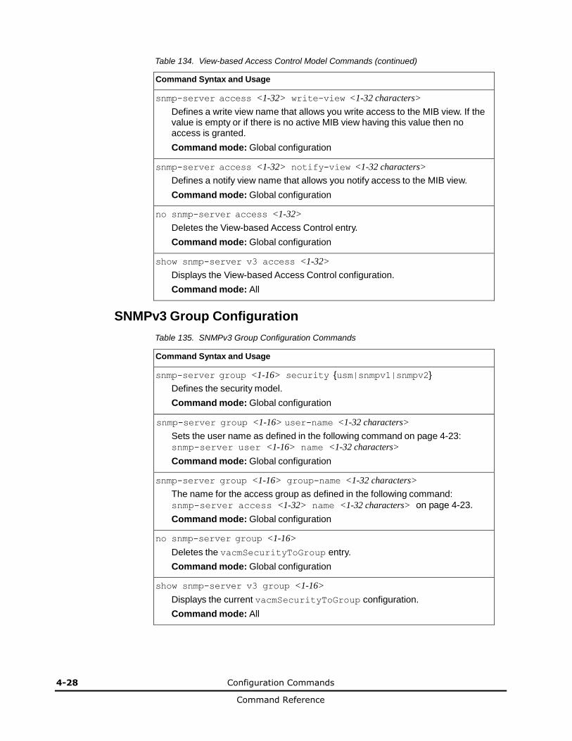
4-28 Configuration Commands
Command Reference
Table 134. View-based Access Control Model Commands (continued)
Command Syntax and Usage
snmp-server access <1-32> write-view <1-32 characters>
Defines a write view name that allows you write access to the MIB view. If the value is empty or if there is no active MIB view having this value then no access is granted.
Command mode: Global configuration
snmp-server access <1-32> notify-view <1-32 characters>
Defines a notify view name that allows you notify access to the MIB view.
Command mode: Global configuration
no snmp-server access <1-32>
Deletes the View-based Access Control entry.
Command mode: Global configuration
show snmp-server v3 access <1-32>
Displays the View-based Access Control configuration.
Command mode: All
SNMPv3 Group Configuration
Table 135. SNMPv3 Group Configuration Commands
Command Syntax and Usage
snmp-server group <1-16> security {usm|snmpv1|snmpv2}
Defines the security model.
Command mode: Global configuration
snmp-server group <1-16> user-name <1-32 characters>
Sets the user name as defined in the following command on page 4-23: snmp-server user <1-16> name <1-32 characters>
Command mode: Global configuration
snmp-server group <1-16> group-name <1-32 characters>
The name for the access group as defined in the following command:
snmp-server access <1-32> name <1-32 characters> on page 4-23.
Command mode: Global configuration
no snmp-server group <1-16>
Deletes the vacmSecurityToGroup entry.
Command mode: Global configuration
show snmp-server v3 group <1-16>
Displays the current vacmSecurityToGroup configuration.
Command mode: All
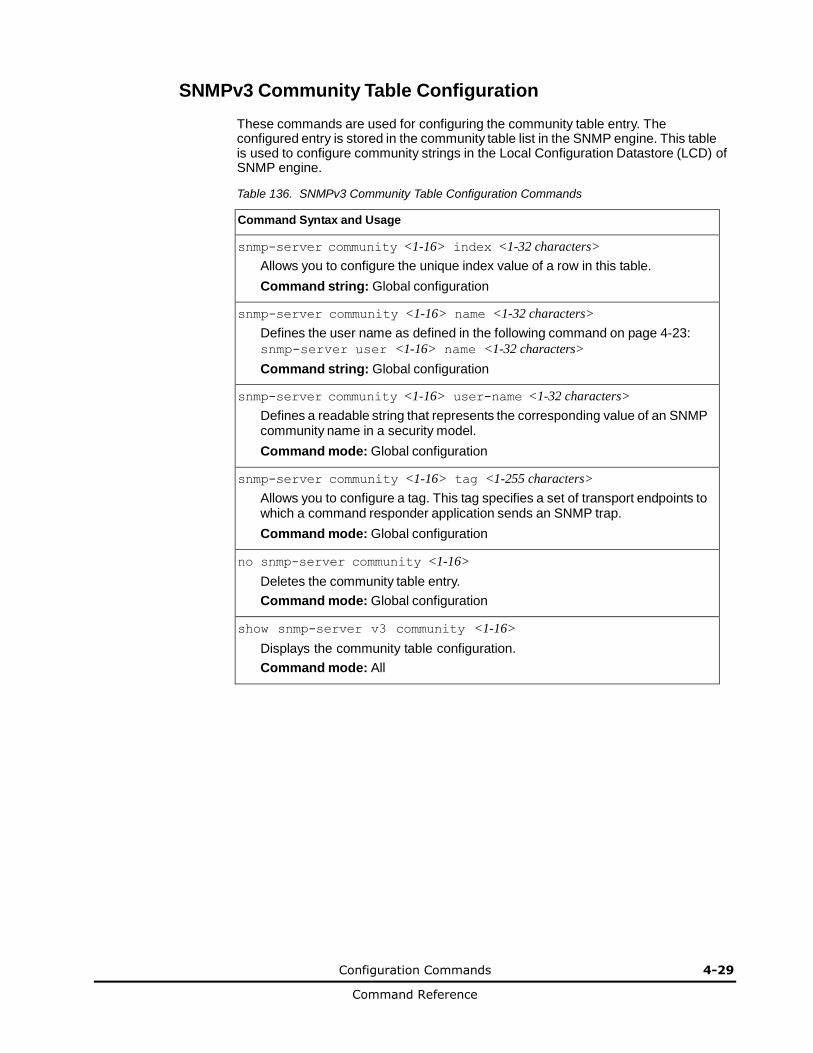
Configuration Commands 4-29
Command Reference
SNMPv3 Community Table Configuration
These commands are used for configuring the community table entry. The configured entry is stored in the community table list in the SNMP engine. This table is used to configure community strings in the Local Configuration Datastore (LCD) of SNMP engine.
Table 136. SNMPv3 Community Table Configuration Commands
Command Syntax and Usage
snmp-server community <1-16> index <1-32 characters>
Allows you to configure the unique index value of a row in this table.
Command string: Global configuration
snmp-server community <1-16> name <1-32 characters>
Defines the user name as defined in the following command on page 4-23:
snmp-server user <1-16> name <1-32 characters>
Command string: Global configuration
snmp-server community <1-16> user-name <1-32 characters>
Defines a readable string that represents the corresponding value of an SNMP community name in a security model.
Command mode: Global configuration
snmp-server community <1-16> tag <1-255 characters>
Allows you to configure a tag. This tag specifies a set of transport endpoints to which a command responder application sends an SNMP trap.
Command mode: Global configuration
no snmp-server community <1-16>
Deletes the community table entry.
Command mode: Global configuration
show snmp-server v3 community <1-16>
Displays the community table configuration.
Command mode: All
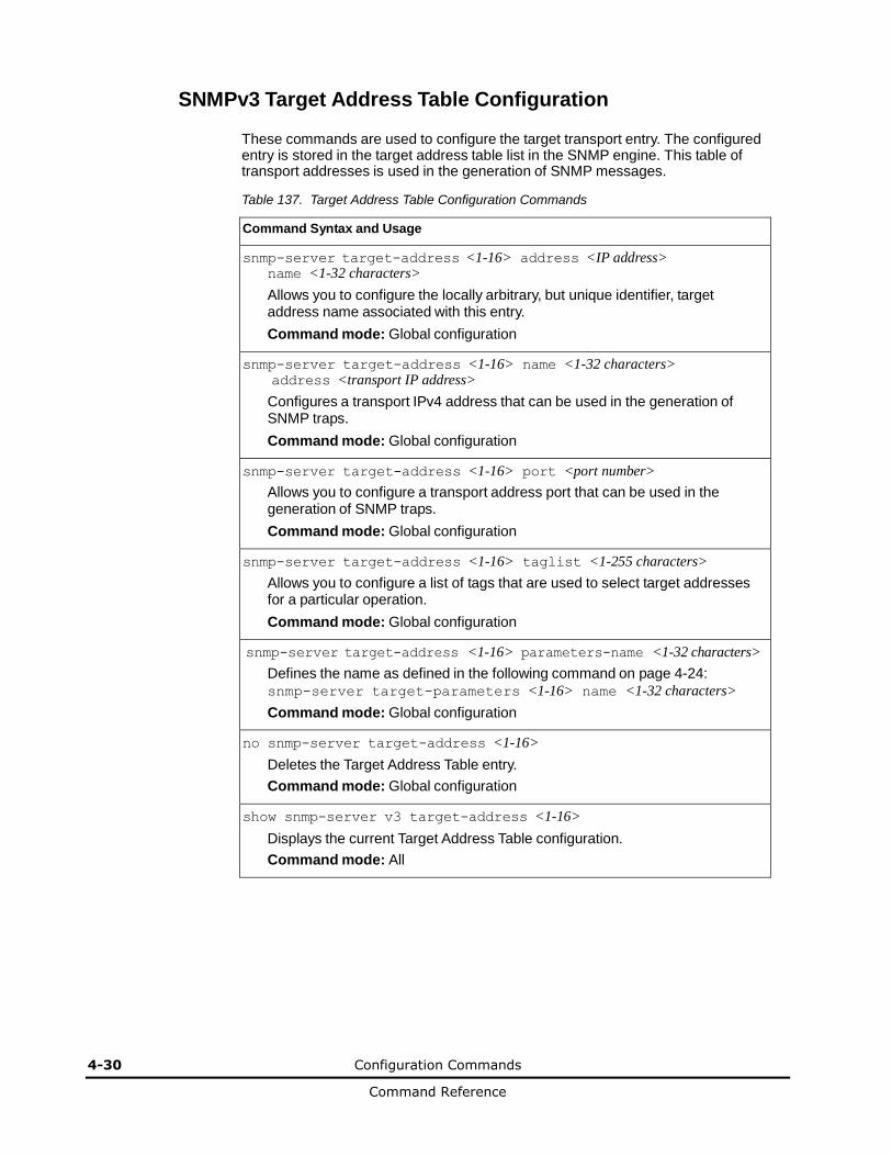
4-30 Configuration Commands
Command Reference
SNMPv3 Target Address Table Configuration
These commands are used to configure the target transport entry. The configured entry is stored in the target address table list in the SNMP engine. This table of transport addresses is used in the generation of SNMP messages.
Table 137. Target Address Table Configuration Commands
Command Syntax and Usage
snmp-server target-address <1-16> address <IP address> name <1-32 characters>
Allows you to configure the locally arbitrary, but unique identifier, target address name associated with this entry.
Command mode: Global configuration
snmp-server target-address <1-16> name <1-32 characters> address <transport IP address>
Configures a transport IPv4 address that can be used in the generation of SNMP traps.
Command mode: Global configuration
snmp-server target-address <1-16> port <port number>
Allows you to configure a transport address port that can be used in the generation of SNMP traps.
Command mode: Global configuration
snmp-server target-address <1-16> taglist <1-255 characters>
Allows you to configure a list of tags that are used to select target addresses for a particular operation.
Command mode: Global configuration
snmp-server target-address <1-16> parameters-name <1-32 characters>
Defines the name as defined in the following command on page 4-24:
snmp-server target-parameters <1-16> name <1-32 characters>
Command mode: Global configuration
no snmp-server target-address <1-16>
Deletes the Target Address Table entry.
Command mode: Global configuration
show snmp-server v3 target-address <1-16>
Displays the current Target Address Table configuration.
Command mode: All
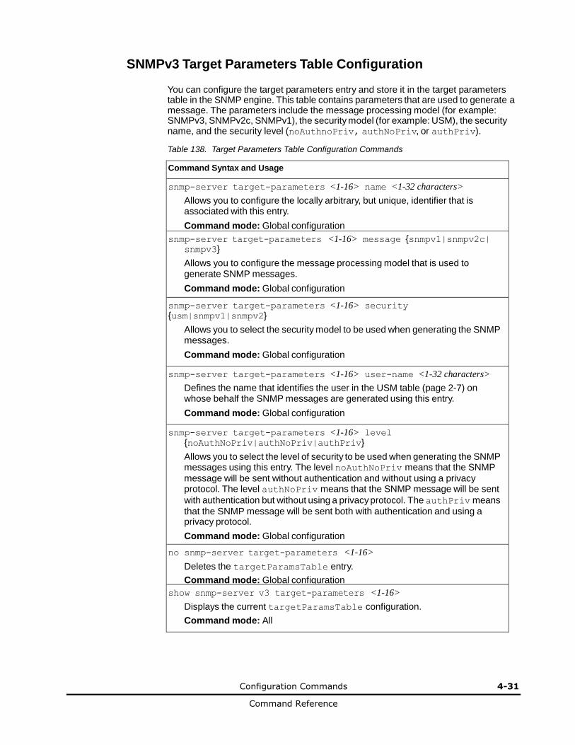
Configuration Commands 4-31
Command Reference
SNMPv3 Target Parameters Table Configuration
You can configure the target parameters entry and store it in the target parameters table in the SNMP engine. This table contains parameters that are used to generate a message. The parameters include the message processing model (for example: SNMPv3, SNMPv2c, SNMPv1), the security model (for example: USM), the security name, and the security level (noAuthnoPriv, authNoPriv, or authPriv).
Table 138. Target Parameters Table Configuration Commands
Command Syntax and Usage
snmp-server target-parameters <1-16> name <1-32 characters>
Allows you to configure the locally arbitrary, but unique, identifier that is associated with this entry.
Command mode: Global configuration
snmp-server target-parameters <1-16> message {snmpv1|snmpv2c| snmpv3}
Allows you to configure the message processing model that is used to generate SNMP messages.
Command mode: Global configuration
snmp-server target-parameters <1-16> security {usm|snmpv1|snmpv2}
Allows you to select the security model to be used when generating the SNMP messages.
Command mode: Global configuration
snmp-server target-parameters <1-16> user-name <1-32 characters>
Defines the name that identifies the user in the USM table (page 2-7) on whose behalf the SNMP messages are generated using this entry.
Command mode: Global configuration
snmp-server target-parameters <1-16> level {noAuthNoPriv|authNoPriv|authPriv}
Allows you to select the level of security to be used when generating the SNMP messages using this entry. The level noAuthNoPriv means that the SNMP
message will be sent without authentication and without using a privacy protocol. The level authNoPriv means that the SNMP message will be sent
with authentication but without using a privacy protocol. The authPriv means
that the SNMP message will be sent both with authentication and using a privacy protocol.
Command mode: Global configuration
no snmp-server target-parameters <1-16>
Deletes the targetParamsTable entry.
Command mode: Global configuration
show snmp-server v3 target-parameters <1-16>
Displays the current targetParamsTable configuration.
Command mode: All

4-32 Configuration Commands
Command Reference
SNMPv3 Notify Table Configuration
SNMPv3 uses Notification Originator to send out traps. A notification typically monitors a system for particular events or conditions, and generates Notification-Class messages based on these events or conditions.
Table 139. Notify Table Commands
Command Syntax and Usage
snmp-server notify <1-16> name <1-32 characters>
Defines a locally arbitrary, but unique, identifier associated with this SNMP notify entry.
Command mode: Global configuration
snmp-server notify <1-16> tag <1-255 characters>
Allows you to configure a tag that contains a tag value which is used to select entries in the Target Address Table. Any entry in the
snmpTargetAddrTable, that matches the value of this tag, is selected.
Command mode: Global configuration
no snmp-server notify <1-16>
Deletes the notify table entry.
Command mode: Global configuration
show snmp-server v3 notify <1-16>
Displays the current notify table configuration.
Command mode: All
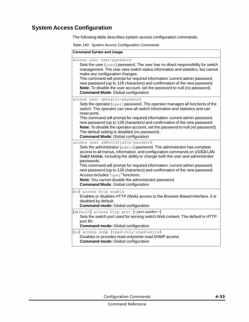
Configuration Commands 4-33
Command Reference
System Access Configuration
The following table describes system access configuration commands.
Table 140. System Access Configuration Commands
Command Syntax and Usage
access user user-password
Sets the user (user) password. The user has no direct responsibility for switch
management. The user view switch status information and statistics, but cannot make any configuration changes. This command will prompt for required information: current admin password, new password (up to 128 characters) and confirmation of the new password. Note: To disable the user account, set the password to null (no password). Command Mode: Global configuration
access user operator-password
Sets the operator (oper)password. The operator manages all functions of the
switch. The operator can view all switch information and statistics and can reset ports. This command will prompt for required information: current admin password, new password (up to 128 characters) and confirmation of the new password. Note: To disable the operator account, set the password to null (no password). The default setting is disabled (no password). Command Mode: Global configuration
access user administrator-password
Sets the administrator (admin) password. The administrator has complete access to all menus, information, and configuration commands on 1/10Gb LAN Switch Module, including the ability to change both the user and administrator passwords. This command will prompt for required information: current admin password, new password (up to 128 characters) and confirmation of the new password.
Access includes “oper” functions.
Note: You cannot disable the administrator password. Command Mode: Global configuration
[no] access http enable
Enables or disables HTTP (Web) access to the Browser-Based Interface. It is disabled by default. Command mode: Global configuration
[default] access http port [<port number>]
Sets the switch port used for serving switch Web content. The default is HTTP port 80. Command mode: Global configuration
[no] access snmp {read-only|read-write}
Disables or provides read-only/write-read SNMP access. Command mode: Global configuration

4-34 Configuration Commands
Command Reference
Table 140. System Access Configuration Commands (continued)
Command Syntax and Usage
[no] access telnet enable
Enables or disables Telnet access. This command is disabled by default.
Command mode: Global configuration
[default] access telnet port [<1-65535>]
Sets an optional Telnet server port number for cases where the server listens for Telnet sessions on a non-standard port.
Command mode: Global configuration
[default] access tftp-port [<1-65535>]
Sets the TFTP port for the switch. The default is port 69.
Command mode: Global configuration
[no] access tsbbi enable
Enables or disables Telnet/SSH configuration through the Browser-Based Interface (BBI).
Command mode: Global configuration
[no] access userbbi enable
Enables or disables user configuration access through the Browser-Based Interface (BBI).
Command mode: Global configuration
show access
Displays the current system access parameters.
Command mode: All
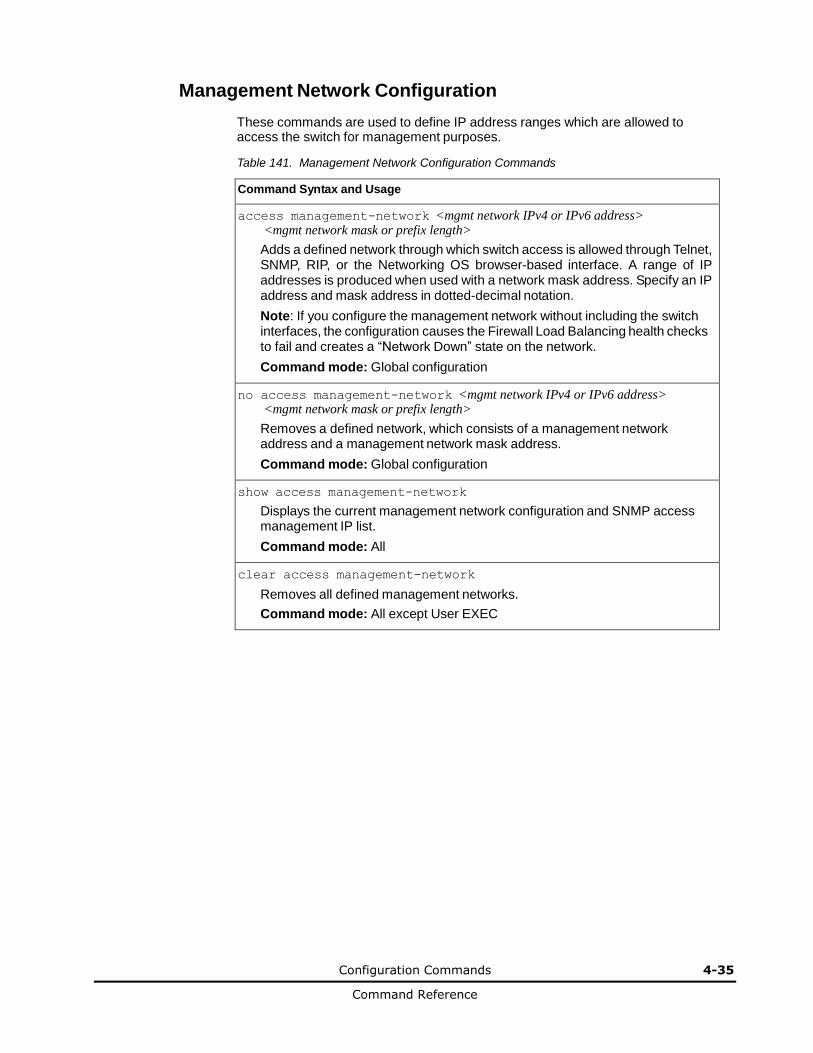
Configuration Commands 4-35
Command Reference
Management Network Configuration
These commands are used to define IP address ranges which are allowed to access the switch for management purposes.
Table 141. Management Network Configuration Commands
Command Syntax and Usage
access management-network <mgmt network IPv4 or IPv6 address> <mgmt network mask or prefix length>
Adds a defined network through which switch access is allowed through Telnet, SNMP, RIP, or the Networking OS browser-based interface. A range of IP addresses is produced when used with a network mask address. Specify an IP address and mask address in dotted-decimal notation.
Note: If you configure the management network without including the switch interfaces, the configuration causes the Firewall Load Balancing health checks to fail and creates a “Network Down” state on the network.
Command mode: Global configuration
no access management-network <mgmt network IPv4 or IPv6 address> <mgmt network mask or prefix length>
Removes a defined network, which consists of a management network address and a management network mask address.
Command mode: Global configuration
show access management-network
Displays the current management network configuration and SNMP access management IP list.
Command mode: All
clear access management-network
Removes all defined management networks.
Command mode: All except User EXEC
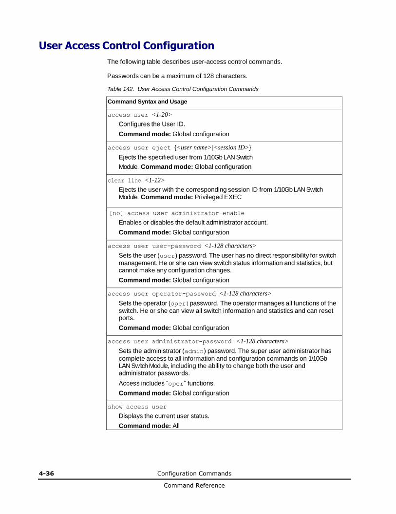
4-36 Configuration Commands
Command Reference
User Access Control Configuration
The following table describes user-access control commands.
Passwords can be a maximum of 128 characters.
Table 142. User Access Control Configuration Commands
Command Syntax and Usage
access user <1-20>
Configures the User ID.
Command mode: Global configuration
access user eject {<user name>|<session ID>}
Ejects the specified user from 1/10Gb LAN Switch
Module. Command mode: Global configuration
clear line <1-12>
Ejects the user with the corresponding session ID from 1/10Gb LAN Switch Module. Command mode: Privileged EXEC
[no] access user administrator-enable
Enables or disables the default administrator account.
Command mode: Global configuration
access user user-password <1-128 characters>
Sets the user (user) password. The user has no direct responsibility for switch management. He or she can view switch status information and statistics, but cannot make any configuration changes.
Command mode: Global configuration
access user operator-password <1-128 characters>
Sets the operator (oper)password. The operator manages all functions of the switch. He or she can view all switch information and statistics and can reset ports.
Command mode: Global configuration
access user administrator-password <1-128 characters>
Sets the administrator (admin) password. The super user administrator has
complete access to all information and configuration commands on 1/10Gb LAN Switch Module, including the ability to change both the user and administrator passwords.
Access includes “oper” functions.
Command mode: Global configuration
show access user
Displays the current user status.
Command mode: All
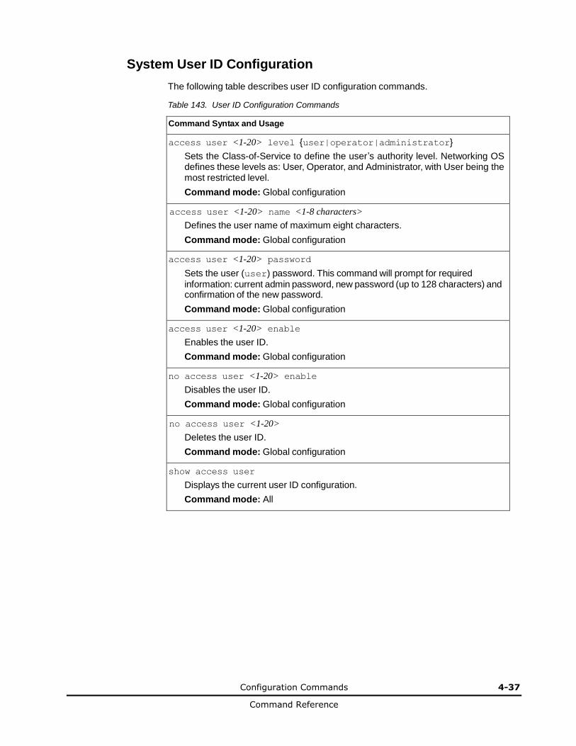
Configuration Commands 4-37
Command Reference
System User ID Configuration
The following table describes user ID configuration commands.
Table 143. User ID Configuration Commands
Command Syntax and Usage
access user <1-20> level {user|operator|administrator}
Sets the Class-of-Service to define the user’s authority level. Networking OS defines these levels as: User, Operator, and Administrator, with User being the most restricted level.
Command mode: Global configuration
access user <1-20> name <1-8 characters>
Defines the user name of maximum eight characters.
Command mode: Global configuration
access user <1-20> password
Sets the user (user) password. This command will prompt for required information: current admin password, new password (up to 128 characters) and confirmation of the new password.
Command mode: Global configuration
access user <1-20> enable
Enables the user ID.
Command mode: Global configuration
no access user <1-20> enable
Disables the user ID.
Command mode: Global configuration
no access user <1-20>
Deletes the user ID.
Command mode: Global configuration
show access user
Displays the current user ID configuration.
Command mode: All

4-38 Configuration Commands
Command Reference
Strong Password Configuration
The following table describes strong password configuration commands.
Table 144. Strong Password Configuration Commands
Command Syntax and Usage
access user strong-password enable
Enables Strong Password requirement.
Command mode: Global configuration
no access user strong-password enable
Disables Strong Password requirement.
Command mode: Global configuration
access user strong-password expiry <1-365>
Configures the number of days allowed before the password must be changed. The default value is 60 days.
Command mode: Global configuration
access user strong-password warning <1-365>
Configures the number of days before password expiration, that a warning is issued to users. The default value is 15 days.
Command mode: Global configuration
access user strong-password faillog <1-255>
Configures the number of failed login attempts allowed before a security notification is logged. The default value is 3 login attempts.
Command mode: Global configuration
[no] access user strong-password lockout
Enables or disables account lockout after a specified number of failed login attempts. Default setting is disabled.
Command mode: Global configuration
access user strong-password faillock <1-10>
Configures the number of failed login attempts that trigger the account lockout. Default value is 6.
Command mode: Global configuration
access user strong-password clear local user
{lockout|fail-attempts} {<username>|all}
Enables locked out accounts or resets failed login counters for all users or for a specific user.
Command mode: Global configuration
show access user strong-password
Displays the current Strong Password configuration.
Command mode: All
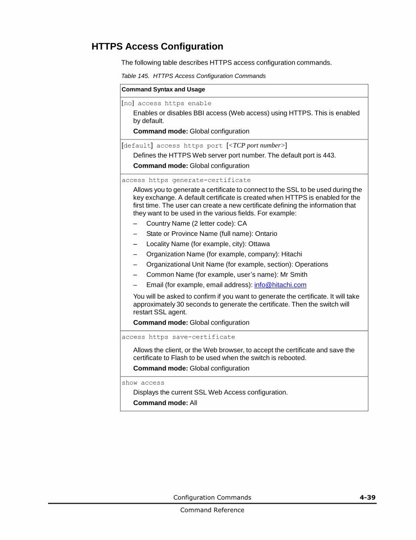
Configuration Commands 4-39
Command Reference
HTTPS Access Configuration
The following table describes HTTPS access configuration commands.
Table 145. HTTPS Access Configuration Commands
Command Syntax and Usage
[no] access https enable
Enables or disables BBI access (Web access) using HTTPS. This is enabled by default.
Command mode: Global configuration
[default] access https port [<TCP port number>]
Defines the HTTPS Web server port number. The default port is 443.
Command mode: Global configuration
access https generate-certificate
Allows you to generate a certificate to connect to the SSL to be used during the key exchange. A default certificate is created when HTTPS is enabled for the first time. The user can create a new certificate defining the information that they want to be used in the various fields. For example:
– Country Name (2 letter code): CA
– State or Province Name (full name): Ontario
– Locality Name (for example, city): Ottawa
– Organization Name (for example, company): Hitachi
– Organizational Unit Name (for example, section): Operations
– Common Name (for example, user’s name): Mr Smith
– Email (for example, email address): [email protected]
You will be asked to confirm if you want to generate the certificate. It will take approximately 30 seconds to generate the certificate. Then the switch will restart SSL agent.
Command mode: Global configuration
access https save-certificate
Allows the client, or the Web browser, to accept the certificate and save the certificate to Flash to be used when the switch is rebooted.
Command mode: Global configuration
show access
Displays the current SSL Web Access configuration.
Command mode: All
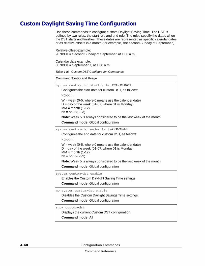
4-40 Configuration Commands
Command Reference
Custom Daylight Saving Time Configuration
Use these commands to configure custom Daylight Saving Time. The DST is defined by two rules, the start rule and end rule. The rules specify the dates when the DST starts and finishes. These dates are represented as specific calendar dates or as relative offsets in a month (for example, 'the second Sunday of September').
Relative offset example: 2070901 = Second Sunday of September, at 1:00 a.m.
Calendar date example: 0070901 = September 7, at 1:00 a.m.
Table 146. Custom DST Configuration Commands
Command Syntax and Usage
system custom-dst start-rule <WDDMMhh>
Configures the start date for custom DST, as follows:
WDMMhh
W = week (0-5, where 0 means use the calender date) D = day of the week (01-07, where 01 is Monday) MM = month (1-12) hh = hour (0-23)
Note: Week 5 is always considered to be the last week of the month.
Command mode: Global configuration
system custom-dst end-rule <WDDMMhh>
Configures the end date for custom DST, as follows:
WDMMhh
W = week (0-5, where 0 means use the calender date) D = day of the week (01-07, where 01 is Monday) MM = month (1-12) hh = hour (0-23)
Note: Week 5 is always considered to be the last week of the month.
Command mode: Global configuration
system custom-dst enable
Enables the Custom Daylight Saving Time settings.
Command mode: Global configuration
no system custom-dst enable
Disables the Custom Daylight Savings Time settings.
Command mode: Global configuration
show custom-dst
Displays the current Custom DST configuration.
Command mode: All
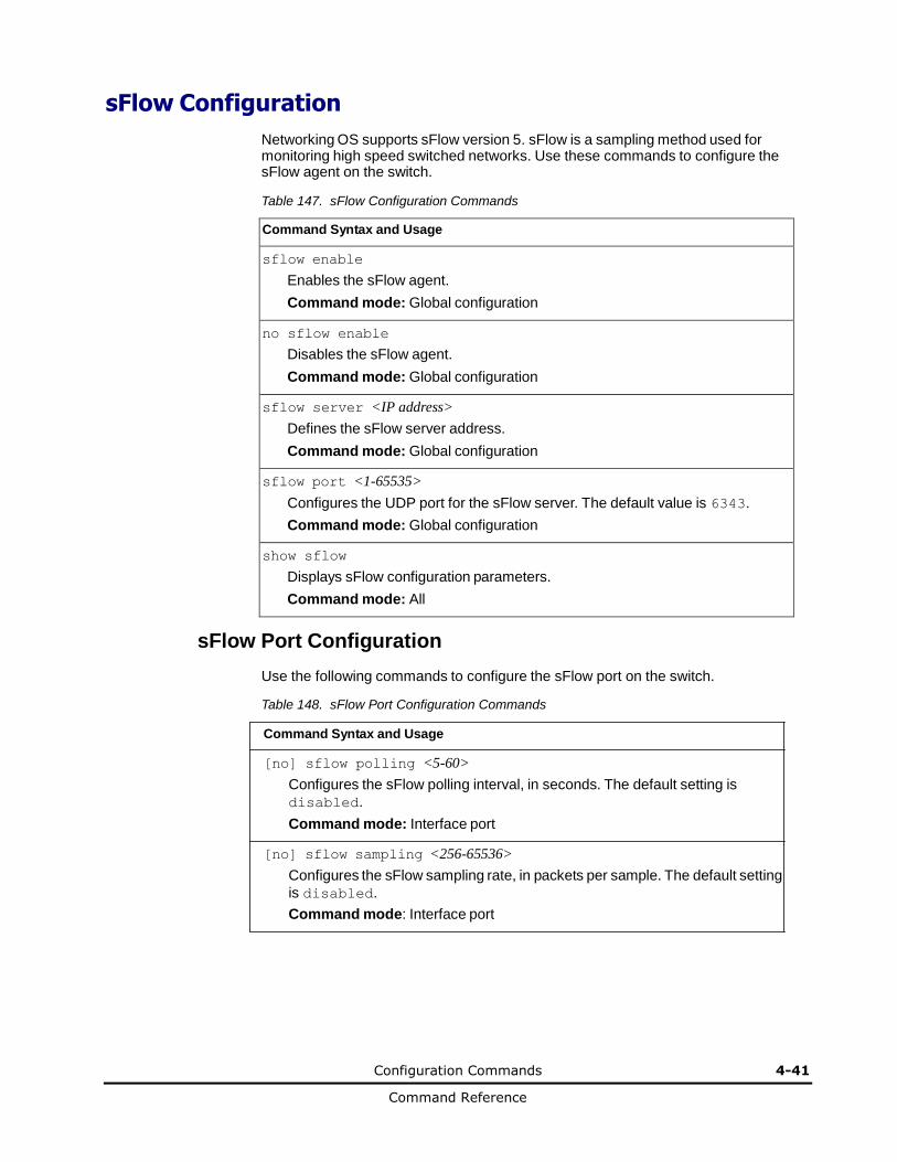
Configuration Commands 4-41
Command Reference
sFlow Configuration
Networking OS supports sFlow version 5. sFlow is a sampling method used for monitoring high speed switched networks. Use these commands to configure the sFlow agent on the switch.
Table 147. sFlow Configuration Commands
Command Syntax and Usage
sflow enable
Enables the sFlow agent.
Command mode: Global configuration
no sflow enable
Disables the sFlow agent.
Command mode: Global configuration
sflow server <IP address>
Defines the sFlow server address.
Command mode: Global configuration
sflow port <1-65535>
Configures the UDP port for the sFlow server. The default value is 6343.
Command mode: Global configuration
show sflow
Displays sFlow configuration parameters.
Command mode: All
sFlow Port Configuration
Use the following commands to configure the sFlow port on the switch.
Table 148. sFlow Port Configuration Commands
Command Syntax and Usage
[no] sflow polling <5-60>
Configures the sFlow polling interval, in seconds. The default setting is
disabled.
Command mode: Interface port
[no] sflow sampling <256-65536>
Configures the sFlow sampling rate, in packets per sample. The default setting
is disabled.
Command mode: Interface port
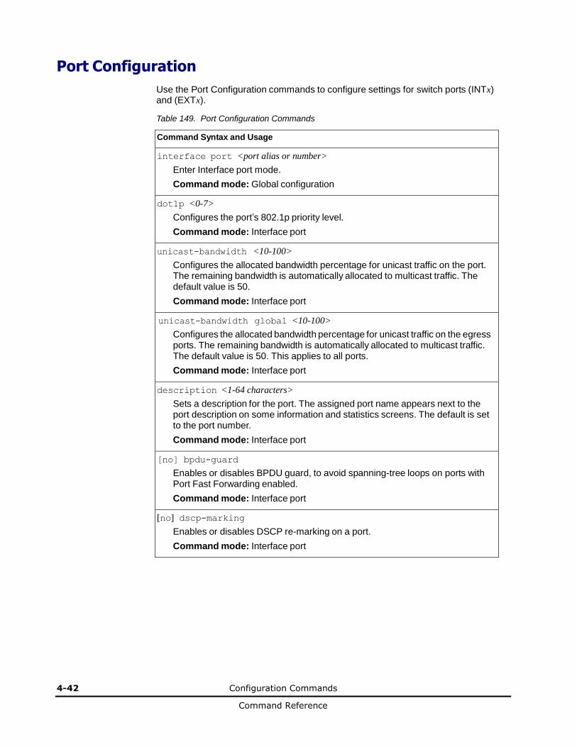
4-42 Configuration Commands
Command Reference
Port Configuration
Use the Port Configuration commands to configure settings for switch ports (INTx) and (EXTx).
Table 149. Port Configuration Commands
Command Syntax and Usage
interface port <port alias or number>
Enter Interface port mode.
Command mode: Global configuration
dot1p <0-7>
Configures the port’s 802.1p priority level.
Command mode: Interface port
unicast-bandwidth <10-100>
Configures the allocated bandwidth percentage for unicast traffic on the port. The remaining bandwidth is automatically allocated to multicast traffic. The default value is 50.
Command mode: Interface port
unicast-bandwidth global <10-100>
Configures the allocated bandwidth percentage for unicast traffic on the egress ports. The remaining bandwidth is automatically allocated to multicast traffic. The default value is 50. This applies to all ports.
Command mode: Interface port
description <1-64 characters>
Sets a description for the port. The assigned port name appears next to the port description on some information and statistics screens. The default is set to the port number.
Command mode: Interface port
[no] bpdu-guard
Enables or disables BPDU guard, to avoid spanning-tree loops on ports with Port Fast Forwarding enabled.
Command mode: Interface port
[no] dscp-marking
Enables or disables DSCP re-marking on a port.
Command mode: Interface port

Configuration Commands 4-43
Command Reference
Table 149. Port Configuration Commands (continued)
Command Syntax and Usage
switchport mode {access|trunk|private-vlan}
Configures the port’s trunking mode:
– access allows association to a single VLAN
– trunk allows association to multiple VLANs
– private-vlan allows association to a private VLAN
Default mode is access.
Note: When switching from access to trunk mode, the port inherits the access VLAN as the trunk Native-VLAN.
Note: When switching from trunk to access mode, the port inherits the trunk Native-VLAN as the access VLAN.
Command mode: Interface port/Interface portchannel
switchport access vlan <1-4094>
Configures the associated VLAN used in access mode. If the VLAN does not exist, it will be created and enabled automatically. Default value is 1 for data ports and 4095 for the management port.
Command mode: Interface port/Interface portchannel
no switchport access vlan
Resets the access VLAN to its default value.
Command mode: Interface port/Interface portchannel
switchport trunk native vlan <1-4094>
Configures the Port VLAN ID (PVID) or Native-VLAN used to carry untagged traffic in trunk mode. If the VLAN does not exist, it will be created and enabled automatically. Default value is 1 for data ports and 4095 for the management port.
Command mode: Interface port/Interface portchannel
switchport trunk allowed vlan [add|remove] <VLAN ID range>
Updates the associated VLANs in trunk mode.If any VLAN in the range does not exist, it will be created and enabled automatically.
– add enables the VLAN range in addition to the current configuration
– remove eliminates the VLAN range from the current configuration
Command mode: Interface port/Interface portchannel
switchport trunk allowed vlan {all|none}
– all associates all existing and enabled VLANs to the port. This is an
operational command applicable only to VLANs currently configured at the
moment of execution. VLANs created afterward will not be associated
automatically. Also, as an operational command, it will not be dumped into
the configuration file.
– none removes the port from all currently associated VLANS except the
default VLAN
Command mode: Interface port/Interface portchannel

4-44 Configuration Commands
Command Reference
Table 149. Port Configuration Commands (continued)
Command Syntax and Usage
[no] switchport private-vlan mapping <primary VLAN>
Enables or disables a private VLAN promiscuous port to/from a primary VLAN.
Command mode: Interface port/Interface portchannel
[no] switchport private-vlan host-association <primary VLAN> <secondary VLAN>
Adds or removes a private VLAN host port to/from a secondary VLAN.
Command mode: Interface port/Interface portchannel
[no] rmon
Enables or disables Remote Monitoring for the port. RMON must be enabled for any RMON configurations to function.
Command mode: Interface port
[no] vlan dot1q tag native
Disables or enables VLAN tag persistence. When disabled, the VLAN tag is removed at egress from packets whose VLAN tag matches the port
PVID/Native-vlan. The default setting is disabled.
Note: In global configuration mode, this is an operational command used to set the VLAN tag persistence on all ports currently tagged at the moment of execution. VLAN tag persistence will not be set automatically for ports tagged afterward. Also, as an operational command, it will not be dumped into the configuration file.
Command mode: Global configuration/Interface port/Interface portchannel
[no] tagpvid-ingress
Enables or disables tagging the ingress frames with the port’s VLAN ID. When enabled, the PVID tag is inserted into untagged and 802.1Q single-tagged
ingress frames as outer VLAN ID. The default setting is disabled.
Command mode: Interface port/Interface portchannel
[no] flood-blocking
Enables or disables port Flood Blocking. When enabled, unicast and multicast packets with unknown destination MAC addresses are blocked from the port.
Command mode: Interface port
[no] mac-address-table mac-notification
Enables or disables MAC Address Notification. With MAC Address Notification enabled, the switch generates a syslog message when a MAC address is added or removed from the MAC address table.
Command mode: Global configuration
[no] learning
Enables or disables FDB learning on the port.
Command mode: Interface port
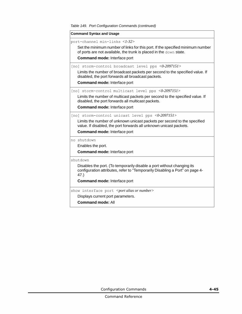
Configuration Commands 4-45
Command Reference
Table 149. Port Configuration Commands (continued)
Command Syntax and Usage
port-channel min-links <1-32>
Set the minimum number of links for this port. If the specified minimum number
of ports are not available, the trunk is placed in the down state.
Command mode: Interface port
[no] storm-control broadcast level pps <0-2097151>
Limits the number of broadcast packets per second to the specified value. If disabled, the port forwards all broadcast packets.
Command mode: Interface port
[no] storm-control multicast level pps <0-2097151>
Limits the number of multicast packets per second to the specified value. If disabled, the port forwards all multicast packets.
Command mode: Interface port
[no] storm-control unicast level pps <0-2097151>
Limits the number of unknown unicast packets per second to the specified value. If disabled, the port forwards all unknown unicast packets.
Command mode: Interface port
no shutdown
Enables the port.
Command mode: Interface port
shutdown
Disables the port. (To temporarily disable a port without changing its configuration attributes, refer to “Temporarily Disabling a Port” on page 4-47.)
Command mode: Interface port
show interface port <port alias or number>
Displays current port parameters.
Command mode: All

4-46 Configuration Commands
Command Reference
Port Error Disable and Recovery Configuration
The Error Disable and Recovery feature allows the switch to automatically disable a port if an error condition is detected on the port. The port remains in the error-disabled state until it is re-enabled manually, or re-enabled automatically by the switch after a timeout period has elapsed. The error-disabled state of a port does not persist across a system reboot.
Table 150. Port Error Disable Commands
Command Syntax and Usage
errdisable recovery
Enables automatic error-recovery for the port. The default setting is enabled.
Note: Error-recovery must be enabled globally before port-level commands become active.
Command mode: Interface port
no errdisable recovery
Enables automatic error-recovery for the port.
Command mode: Interface port
show interface port <port alias or number> errdisable
Displays current port Error Disable parameters.
Command mode: All
Port Link Configuration
Use these commands to set flow control for the port link.
Table 151. Port Link Configuration Commands
Command Syntax and Usage
speed {1000|10000|auto}
Sets the link speed. Some options are not valid on all ports. The choices include:
– 1000 Mbps
– 10000 Mps
– any (auto negotiate port speed)
Command mode: Interface port
duplex {full|half|auto}
Sets the operating mode. The choices include:
– Auto negotiation (default)
– Half-duplex
– Full-duplex
Command mode: Interface port
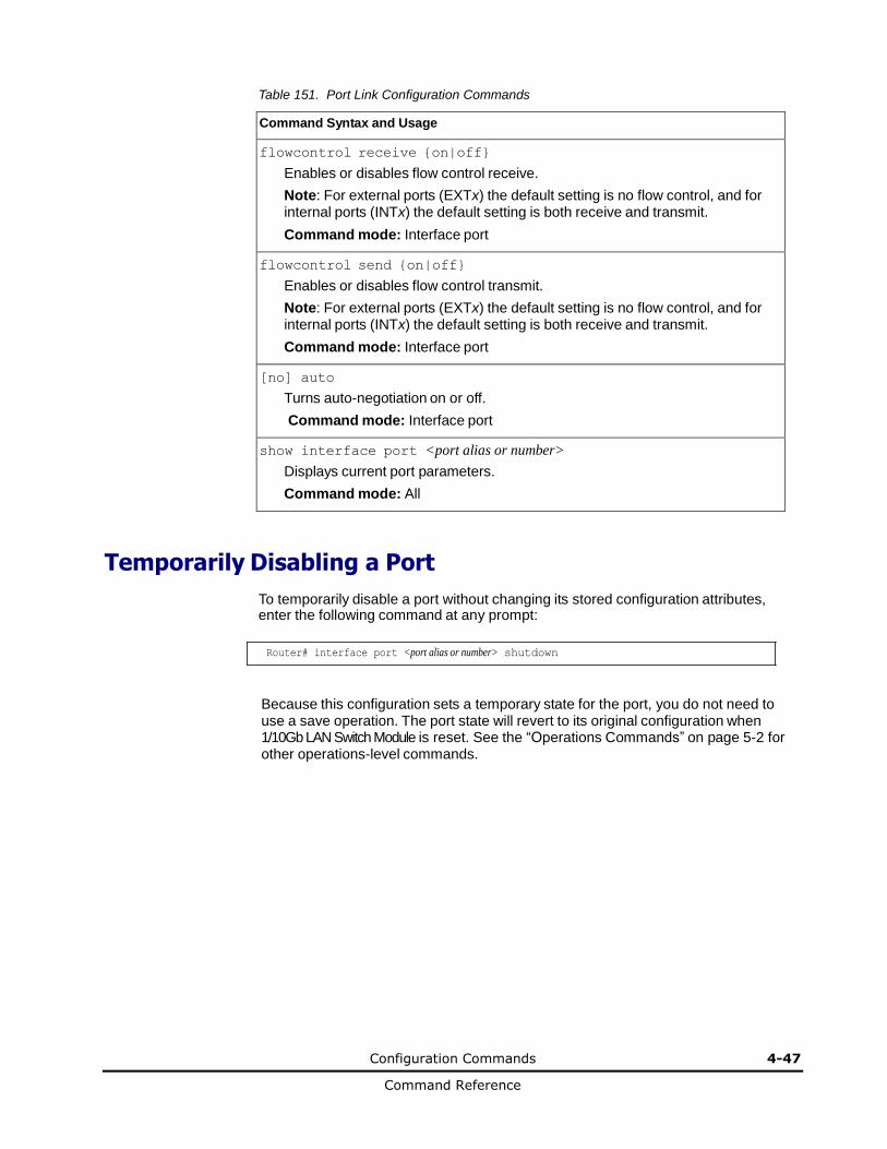
Configuration Commands 4-47
Command Reference
Table 151. Port Link Configuration Commands
Command Syntax and Usage
flowcontrol receive {on|off}
Enables or disables flow control receive.
Note: For external ports (EXTx) the default setting is no flow control, and for internal ports (INTx) the default setting is both receive and transmit.
Command mode: Interface port
flowcontrol send {on|off}
Enables or disables flow control transmit.
Note: For external ports (EXTx) the default setting is no flow control, and for internal ports (INTx) the default setting is both receive and transmit.
Command mode: Interface port
[no] auto
Turns auto-negotiation on or off.
Command mode: Interface port
show interface port <port alias or number>
Displays current port parameters.
Command mode: All
Temporarily Disabling a Port To temporarily disable a port without changing its stored configuration attributes, enter the following command at any prompt:
Router# interface port <port alias or number> shutdown
Because this configuration sets a temporary state for the port, you do not need to use a save operation. The port state will revert to its original configuration when 1/10Gb LAN Switch Module is reset. See the “Operations Commands” on page 5-2 for other operations-level commands.
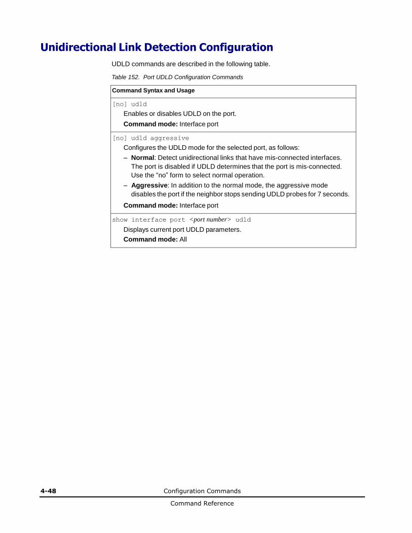
4-48 Configuration Commands
Command Reference
Unidirectional Link Detection Configuration
UDLD commands are described in the following table.
Table 152. Port UDLD Configuration Commands
Command Syntax and Usage
[no] udld
Enables or disables UDLD on the port.
Command mode: Interface port
[no] udld aggressive
Configures the UDLD mode for the selected port, as follows:
– Normal: Detect unidirectional links that have mis-connected interfaces.
The port is disabled if UDLD determines that the port is mis-connected.
Use the “no” form to select normal operation.
– Aggressive: In addition to the normal mode, the aggressive mode
disables the port if the neighbor stops sending UDLD probes for 7 seconds.
Command mode: Interface port
show interface port <port number> udld
Displays current port UDLD parameters.
Command mode: All
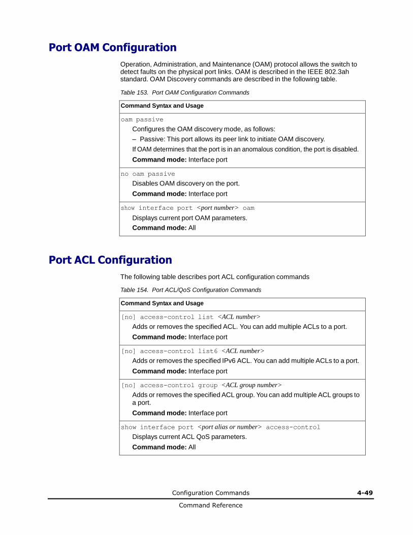
Configuration Commands 4-49
Command Reference
Port OAM Configuration
Operation, Administration, and Maintenance (OAM) protocol allows the switch to detect faults on the physical port links. OAM is described in the IEEE 802.3ah standard. OAM Discovery commands are described in the following table.
Table 153. Port OAM Configuration Commands
Command Syntax and Usage
oam passive
Configures the OAM discovery mode, as follows:
– Passive: This port allows its peer link to initiate OAM discovery.
If OAM determines that the port is in an anomalous condition, the port is disabled.
Command mode: Interface port
no oam passive
Disables OAM discovery on the port.
Command mode: Interface port
show interface port <port number> oam
Displays current port OAM parameters.
Command mode: All
Port ACL Configuration
The following table describes port ACL configuration commands
Table 154. Port ACL/QoS Configuration Commands
Command Syntax and Usage
[no] access-control list <ACL number>
Adds or removes the specified ACL. You can add multiple ACLs to a port.
Command mode: Interface port
[no] access-control list6 <ACL number>
Adds or removes the specified IPv6 ACL. You can add multiple ACLs to a port.
Command mode: Interface port
[no] access-control group <ACL group number>
Adds or removes the specified ACL group. You can add multiple ACL groups to a port.
Command mode: Interface port
show interface port <port alias or number> access-control
Displays current ACL QoS parameters.
Command mode: All
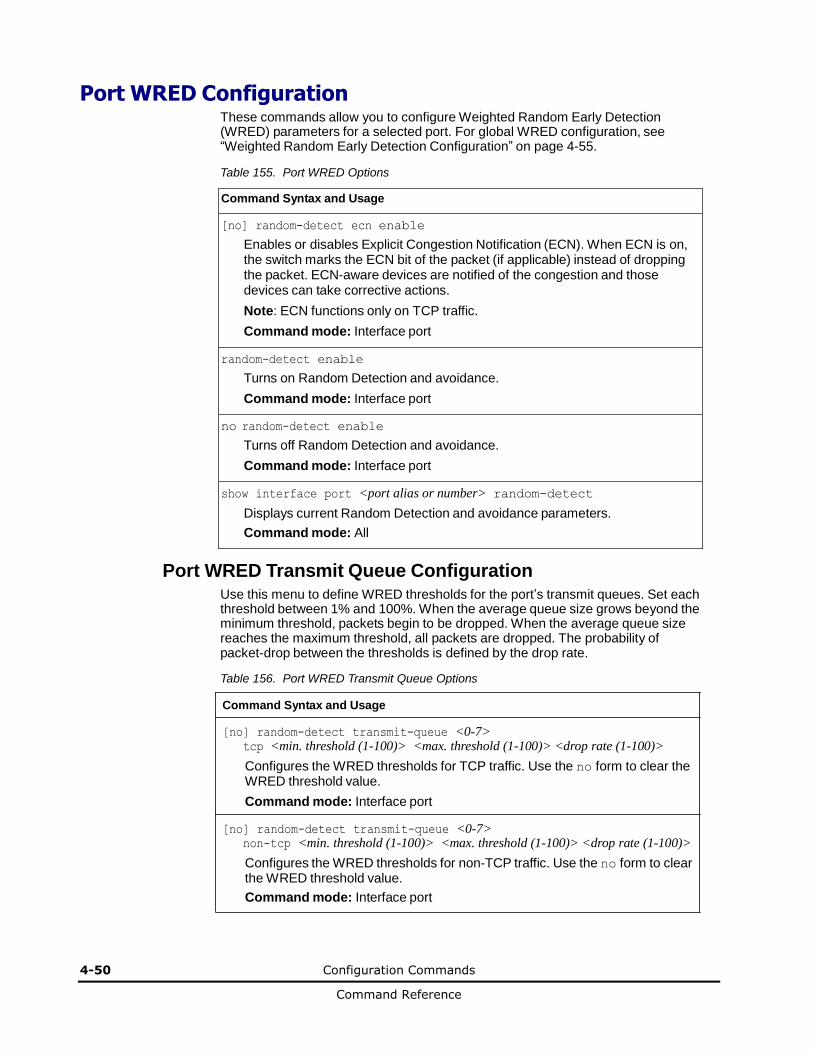
4-50 Configuration Commands
Command Reference
Port WRED Configuration These commands allow you to configure Weighted Random Early Detection (WRED) parameters for a selected port. For global WRED configuration, see “Weighted Random Early Detection Configuration” on page 4-55.
Table 155. Port WRED Options
Command Syntax and Usage
[no] random-detect ecn enable
Enables or disables Explicit Congestion Notification (ECN). When ECN is on, the switch marks the ECN bit of the packet (if applicable) instead of dropping the packet. ECN-aware devices are notified of the congestion and those devices can take corrective actions.
Note: ECN functions only on TCP traffic.
Command mode: Interface port
random-detect enable
Turns on Random Detection and avoidance.
Command mode: Interface port
no random-detect enable
Turns off Random Detection and avoidance.
Command mode: Interface port
show interface port <port alias or number> random-detect
Displays current Random Detection and avoidance parameters.
Command mode: All
Port WRED Transmit Queue Configuration Use this menu to define WRED thresholds for the port’s transmit queues. Set each threshold between 1% and 100%. When the average queue size grows beyond the minimum threshold, packets begin to be dropped. When the average queue size reaches the maximum threshold, all packets are dropped. The probability of packet-drop between the thresholds is defined by the drop rate.
Table 156. Port WRED Transmit Queue Options
Command Syntax and Usage
[no] random-detect transmit-queue <0-7> tcp <min. threshold (1-100)> <max. threshold (1-100)> <drop rate (1-100)>
Configures the WRED thresholds for TCP traffic. Use the no form to clear the WRED threshold value.
Command mode: Interface port
[no] random-detect transmit-queue <0-7> non-tcp <min. threshold (1-100)> <max. threshold (1-100)> <drop rate (1-100)>
Configures the WRED thresholds for non-TCP traffic. Use the no form to clear the WRED threshold value.
Command mode: Interface port
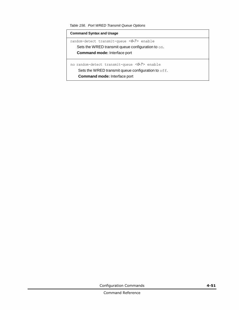
Configuration Commands 4-51
Command Reference
Table 156. Port WRED Transmit Queue Options
Command Syntax and Usage
random-detect transmit-queue <0-7> enable
Sets the WRED transmit queue configuration to on.
Command mode: Interface port
no random-detect transmit-queue <0-7> enable
Sets the WRED transmit queue configuration to off.
Command mode: Interface port
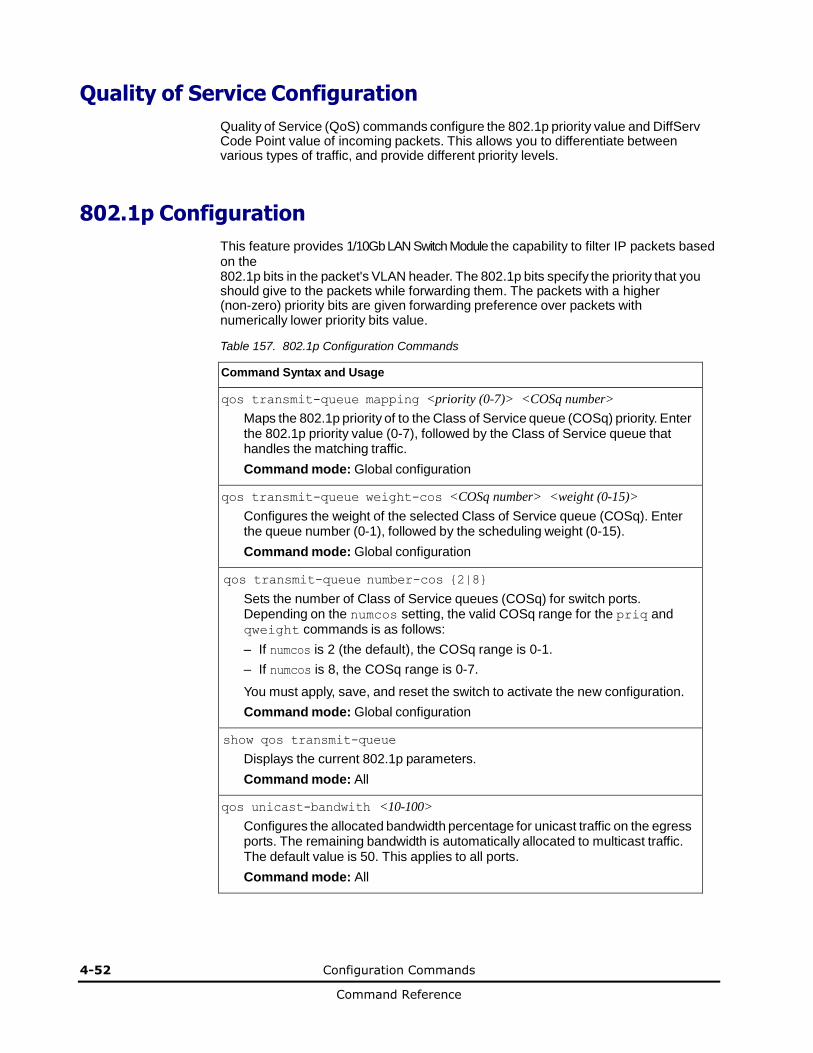
4-52 Configuration Commands
Command Reference
Quality of Service Configuration
Quality of Service (QoS) commands configure the 802.1p priority value and DiffServ Code Point value of incoming packets. This allows you to differentiate between various types of traffic, and provide different priority levels.
802.1p Configuration
This feature provides 1/10Gb LAN Switch Module the capability to filter IP packets based on the 802.1p bits in the packet's VLAN header. The 802.1p bits specify the priority that you should give to the packets while forwarding them. The packets with a higher (non-zero) priority bits are given forwarding preference over packets with numerically lower priority bits value.
Table 157. 802.1p Configuration Commands
Command Syntax and Usage
qos transmit-queue mapping <priority (0-7)> <COSq number>
Maps the 802.1p priority of to the Class of Service queue (COSq) priority. Enter the 802.1p priority value (0-7), followed by the Class of Service queue that handles the matching traffic.
Command mode: Global configuration
qos transmit-queue weight-cos <COSq number> <weight (0-15)>
Configures the weight of the selected Class of Service queue (COSq). Enter the queue number (0-1), followed by the scheduling weight (0-15).
Command mode: Global configuration
qos transmit-queue number-cos {2|8}
Sets the number of Class of Service queues (COSq) for switch ports. Depending on the numcos setting, the valid COSq range for the priq and qweight commands is as follows:
– If numcos is 2 (the default), the COSq range is 0-1.
– If numcos is 8, the COSq range is 0-7.
You must apply, save, and reset the switch to activate the new configuration.
Command mode: Global configuration
show qos transmit-queue
Displays the current 802.1p parameters.
Command mode: All
qos unicast-bandwith <10-100>
Configures the allocated bandwidth percentage for unicast traffic on the egress ports. The remaining bandwidth is automatically allocated to multicast traffic. The default value is 50. This applies to all ports.
Command mode: All
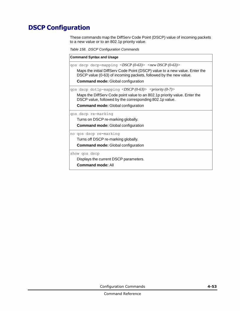
Configuration Commands 4-53
Command Reference
DSCP Configuration
These commands map the DiffServ Code Point (DSCP) value of incoming packets to a new value or to an 802.1p priority value.
Table 158. DSCP Configuration Commands
Command Syntax and Usage
qos dscp dscp-mapping <DSCP (0-63)> <new DSCP (0-63)>
Maps the initial DiffServ Code Point (DSCP) value to a new value. Enter the DSCP value (0-63) of incoming packets, followed by the new value.
Command mode: Global configuration
qos dscp dot1p-mapping <DSCP (0-63)> <priority (0-7)>
Maps the DiffServ Code point value to an 802.1p priority value. Enter the DSCP value, followed by the corresponding 802.1p value.
Command mode: Global configuration
qos dscp re-marking
Turns on DSCP re-marking globally.
Command mode: Global configuration
no qos dscp re-marking
Turns off DSCP re-marking globally.
Command mode: Global configuration
show qos dscp
Displays the current DSCP parameters.
Command mode: All
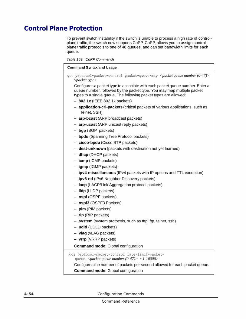
4-54 Configuration Commands
Command Reference
Control Plane Protection
To prevent switch instability if the switch is unable to process a high rate of control-plane traffic, the switch now supports CoPP. CoPP, allows you to assign control-plane traffic protocols to one of 48 queues, and can set bandwidth limits for each queue.
Table 159. CoPP Commands
Command Syntax and Usage
qos protocol-packet-control packet-queue-map <packet queue number (0-47)> <packet type>
Configures a packet type to associate with each packet queue number. Enter a queue number, followed by the packet type. You may map multiple packet types to a single queue. The following packet types are allowed:
– 802.1x (IEEE 802.1x packets)
– application-cri-packets (critical packets of various applications, such as
Telnet, SSH)
– arp-bcast (ARP broadcast packets)
– arp-ucast (ARP unicast reply packets)
– bgp (BGP packets)
– bpdu (Spanning Tree Protocol packets)
– cisco-bpdu (Cisco STP packets)
– dest-unknown (packets with destination not yet learned)
– dhcp (DHCP packets)
– icmp (ICMP packets)
– igmp (IGMP packets)
– ipv4-miscellaneous (IPv4 packets with IP options and TTL exception)
– ipv6-nd (IPv6 Neighbor Discovery packets)
– lacp (LACP/Link Aggregation protocol packets)
– lldp (LLDP packets)
– ospf (OSPF packets)
– ospf3 (OSPF3 Packets)
– pim (PIM packets)
– rip (RIP packets)
– system (system protocols, such as tftp, ftp, telnet, ssh)
– udld (UDLD packets)
– vlag (vLAG packets)
– vrrp (VRRP packets)
Command mode: Global configuration
qos protocol-packet-control rate-limit-packet-
queue <packet queue number (0-47)> <1-10000>
Configures the number of packets per second allowed for each packet queue.
Command mode: Global configuration
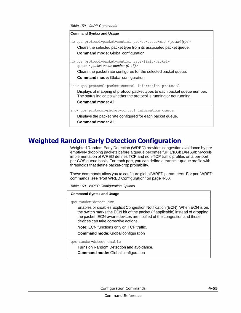
Configuration Commands 4-55
Command Reference
Table 159. CoPP Commands
Command Syntax and Usage
no qos protocol-packet-control packet-queue-map <packet type>
Clears the selected packet type from its associated packet queue.
Command mode: Global configuration
no qos protocol-packet-control rate-limit-packet-
queue <packet queue number (0-47)>
Clears the packet rate configured for the selected packet queue.
Command mode: Global configuration
show qos protocol-packet-control information protocol
Displays of mapping of protocol packet types to each packet queue number. The status indicates whether the protocol is running or not running.
Command mode: All
show qos protocol-packet-control information queue
Displays the packet rate configured for each packet queue.
Command mode: All
Weighted Random Early Detection Configuration Weighted Random Early Detection (WRED) provides congestion avoidance by pre-emptively dropping packets before a queue becomes full. 1/10Gb LAN Switch Module implementation of WRED defines TCP and non-TCP traffic profiles on a per-port, per COS queue basis. For each port, you can define a transmit-queue profile with thresholds that define packet-drop probability.
These commands allow you to configure global WRED parameters. For port WRED commands, see “Port WRED Configuration” on page 4-50.
Table 160. WRED Configuration Options
Command Syntax and Usage
qos random-detect ecn
Enables or disables Explicit Congestion Notification (ECN). When ECN is on, the switch marks the ECN bit of the packet (if applicable) instead of dropping the packet. ECN-aware devices are notified of the congestion and those devices can take corrective actions.
Note: ECN functions only on TCP traffic.
Command mode: Global configuration
qos random-detect enable
Turns on Random Detection and avoidance.
Command mode: Global configuration
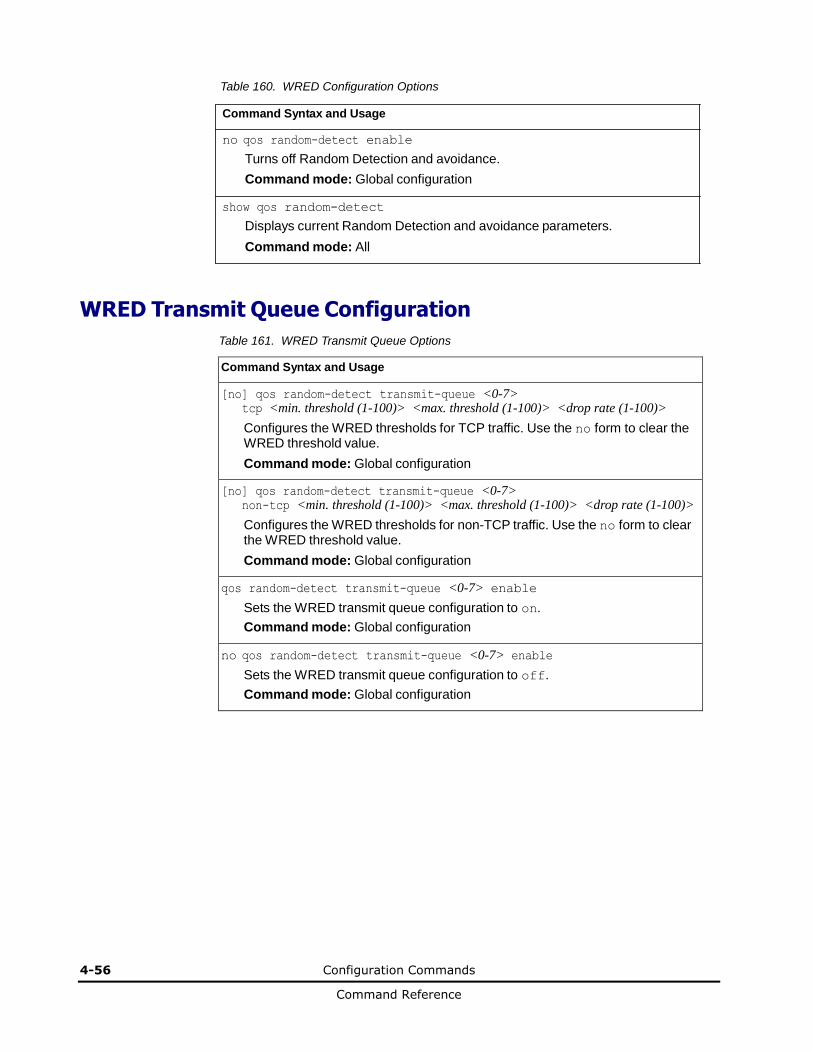
4-56 Configuration Commands
Command Reference
Table 160. WRED Configuration Options
Command Syntax and Usage
no qos random-detect enable
Turns off Random Detection and avoidance.
Command mode: Global configuration
show qos random-detect
Displays current Random Detection and avoidance parameters.
Command mode: All
WRED Transmit Queue Configuration
Table 161. WRED Transmit Queue Options
Command Syntax and Usage
[no] qos random-detect transmit-queue <0-7> tcp <min. threshold (1-100)> <max. threshold (1-100)> <drop rate (1-100)>
Configures the WRED thresholds for TCP traffic. Use the no form to clear the WRED threshold value.
Command mode: Global configuration
[no] qos random-detect transmit-queue <0-7> non-tcp <min. threshold (1-100)> <max. threshold (1-100)> <drop rate (1-100)>
Configures the WRED thresholds for non-TCP traffic. Use the no form to clear the WRED threshold value.
Command mode: Global configuration
qos random-detect transmit-queue <0-7> enable
Sets the WRED transmit queue configuration to on.
Command mode: Global configuration
no qos random-detect transmit-queue <0-7> enable
Sets the WRED transmit queue configuration to off.
Command mode: Global configuration

Configuration Commands 4-57
Command Reference
Access Control Configuration
Use these commands to create Access Control Lists and ACL Groups. ACLs define matching criteria used for IP filtering and Quality of Service functions.
For information about assigning ACLs to ports, see “Port ACL Configuration” on page 4-49.
Table 162. General ACL Configuration Commands
Command Syntax and Usage
[no] access-control list <1-640>
Configures an Access Control List.
Command mode: Global configuration
To view command options, see page 4-58.
[no] access-control group <1-640>
Configures an ACL Group.
Command mode: Global configuration
To view command options, see page 4-73.
show access-control
Displays the current ACL parameters.
Command mode: All

4-58 Configuration Commands
Command Reference
Access Control List Configuration
These commands allow you to define filtering criteria for each Access Control List (ACL).
Table 163. ACL Configuration Commands
Command Syntax and Usage
[no] access-control list <1-640> egress-port port <port alias or number>
Configures the ACL to function on egress packets.
Command mode: Global configuration
access-control list <1-640> action {permit|deny| set-priority <0-7>}
Configures a filter action for packets that match the ACL definitions. You can choose to permit (pass) or deny (drop) packets, or set the 802.1p priority level (0-7).
Command mode: Global configuration
[no] access-control list <1-640> statistics
Enables or disables the statistics collection for the Access Control List.
Command mode: Global configuration
default access-control list <1-640>
Resets the ACL parameters to their default values.
Command mode: Global configuration
show access-control list <1-640>
Displays the current ACL parameters.
Command mode: All
[no] access-control list6 <1-128>
Configures an IPv6 Access Control List. To view command options, see page 4-62.
Command mode: Global configuration
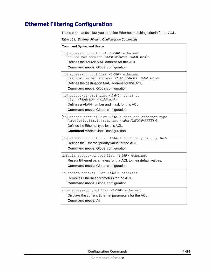
Configuration Commands 4-59
Command Reference
Ethernet Filtering Configuration
These commands allow you to define Ethernet matching criteria for an ACL.
Table 164. Ethernet Filtering Configuration Commands
Command Syntax and Usage
[no] access-control list <1-640> ethernet source-mac-address <MAC address> <MAC mask>
Defines the source MAC address for this ACL.
Command mode: Global configuration
[no] access-control list <1-640> ethernet destination-mac-address <MAC address> <MAC mask>
Defines the destination MAC address for this ACL.
Command mode: Global configuration
[no] access-control list <1-640> ethernet vlan <VLAN ID> <VLAN mask>
Defines a VLAN number and mask for this ACL.
Command mode: Global configuration
[no] access-control list <1-640> ethernet ethernet-type {arp|ip|ipv6|mpls|rarp|any|<other (0x600-0xFFFF)>}
Defines the Ethernet type for this ACL.
Command mode: Global configuration
[no] access-control list <1-640> ethernet priority <0-7>
Defines the Ethernet priority value for the ACL.
Command mode: Global configuration
default access-control list <1-640> ethernet
Resets Ethernet parameters for the ACL to their default values.
Command mode: Global configuration
no access-control list <1-640> ethernet
Removes Ethernet parameters for the ACL.
Command mode: Global configuration
show access-control list <1-640> ethernet
Displays the current Ethernet parameters for the ACL.
Command mode: All
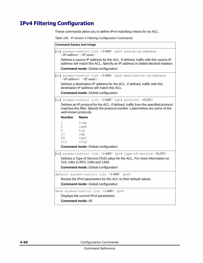
4-60 Configuration Commands
Command Reference
IPv4 Filtering Configuration
These commands allow you to define IPv4 matching criteria for an ACL.
Table 165. IP version 4 Filtering Configuration Commands
Command Syntax and Usage
[no] access-control list <1-640> ipv4 source-ip-address <IP address> <IP mask>
Defines a source IP address for the ACL. If defined, traffic with this source IP address will match this ACL. Specify an IP address in dotted decimal notation.
Command mode: Global configuration
[no] access-control list <1-640> ipv4 destination-ip-address <IP address> <IP mask>
Defines a destination IP address for the ACL. If defined, traffic with this destination IP address will match this ACL.
Command mode: Global configuration
[no] access-control list <1-640> ipv4 protocol <0-255>
Defines an IP protocol for the ACL. If defined, traffic from the specified protocol matches this filter. Specify the protocol number. Listed below are some of the well-known protocols.
Number Name
1 icmp
2 igmp
6 tcp
17 udp
89 ospf
112 vrrp
Command mode: Global configuration
[no] access-control list <1-640> ipv4 type-of-service <0-255>
Defines a Type of Service (ToS) value for the ACL. For more information on ToS, refer to RFC 1340 and 1349.
Command mode: Global configuration
default access-control list <1-640> ipv4
Resets the IPv4 parameters for the ACL to their default values.
Command mode: Global configuration
show access-control list <1-640> ipv4
Displays the current IPv4 parameters.
Command mode: All

Configuration Commands 4-61
Command Reference
TCP/UDP Filtering Configuration
These commands allow you to define TCP/UDP matching criteria for an ACL.
Table 166. TCP/UDP Filtering Configuration Commands
Command Syntax and Usage
[no] access-control list <1-640> tcp-udp source-port <1-65535> <mask (0xFFFF)>
Defines a source port for the ACL. If defined, traffic with the specified TCP or UDP source port will match this ACL. Specify the port number. Listed below are some of the well-known ports:
Number Name
20 ftp-data
21 ftp
22 ssh
23 telnet
25 smtp
37 time
42 name
43 whois
53 domain
69 tftp
70 gopher
79 finger
80 http
Command mode: Global configuration
[no] access-control list <1-640> tcp-udp destination-port <1-65535> <mask (0xFFFF)>
Defines a destination port for the ACL. If defined, traffic with the specified TCP or UDP destination port will match this ACL. Specify the port number, just as with sport above.
Command mode: Global configuration
[no] access-control list <1-640> tcp-udp flags <value (0x0-0x3f)> <mask (0x0-0x3f)>
Defines a TCP/UDP flag for the ACL.
Command mode: Global configuration
default access-control list <1-640> tcp-udp
Resets the TCP/UDP parameters for the ACL to their default values.
Command mode: Global configuration
show access-control list <1-640> tcp-udp
Displays the current TCP/UDP Filtering parameters.
Command mode: All
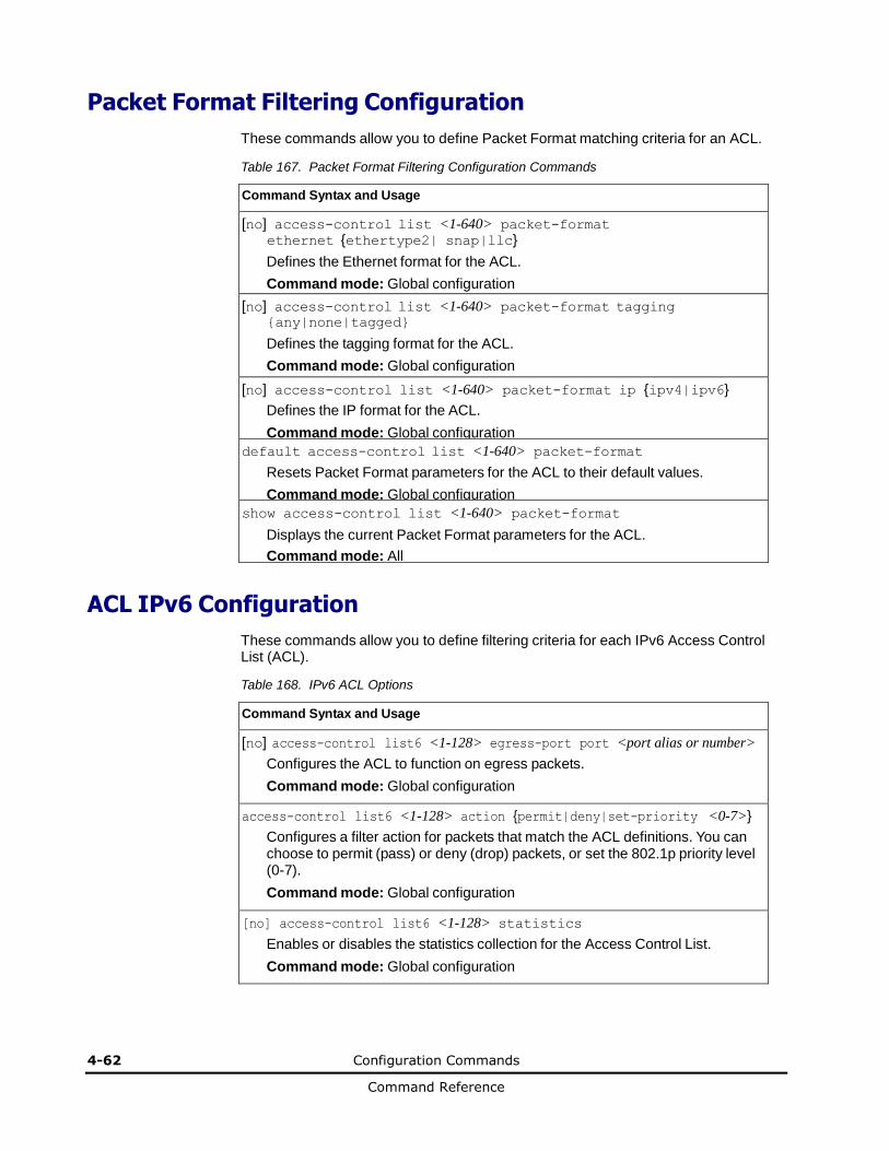
4-62 Configuration Commands
Command Reference
Packet Format Filtering Configuration
These commands allow you to define Packet Format matching criteria for an ACL.
Table 167. Packet Format Filtering Configuration Commands
Command Syntax and Usage
[no] access-control list <1-640> packet-format ethernet {ethertype2| snap|llc}
Defines the Ethernet format for the ACL.
Command mode: Global configuration
[no] access-control list <1-640> packet-format tagging {any|none|tagged}
Defines the tagging format for the ACL.
Command mode: Global configuration
[no] access-control list <1-640> packet-format ip {ipv4|ipv6}
Defines the IP format for the ACL.
Command mode: Global configuration
default access-control list <1-640> packet-format
Resets Packet Format parameters for the ACL to their default values.
Command mode: Global configuration
show access-control list <1-640> packet-format
Displays the current Packet Format parameters for the ACL.
Command mode: All
ACL IPv6 Configuration
These commands allow you to define filtering criteria for each IPv6 Access Control List (ACL).
Table 168. IPv6 ACL Options
Command Syntax and Usage
[no] access-control list6 <1-128> egress-port port <port alias or number>
Configures the ACL to function on egress packets.
Command mode: Global configuration
access-control list6 <1-128> action {permit|deny|set-priority <0-7>}
Configures a filter action for packets that match the ACL definitions. You can choose to permit (pass) or deny (drop) packets, or set the 802.1p priority level (0-7).
Command mode: Global configuration
[no] access-control list6 <1-128> statistics
Enables or disables the statistics collection for the Access Control List.
Command mode: Global configuration
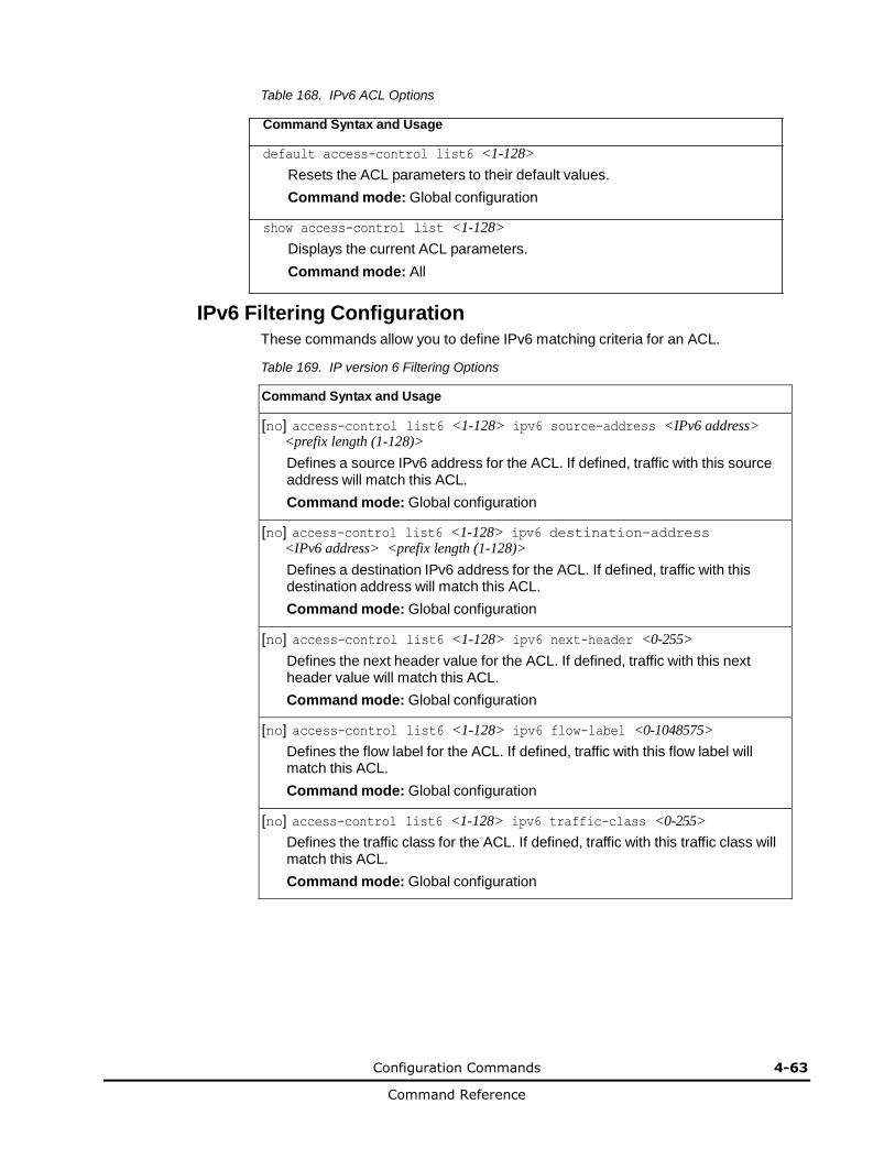
Configuration Commands 4-63
Command Reference
Table 168. IPv6 ACL Options
Command Syntax and Usage
default access-control list6 <1-128>
Resets the ACL parameters to their default values.
Command mode: Global configuration
show access-control list <1-128>
Displays the current ACL parameters.
Command mode: All
IPv6 Filtering Configuration
These commands allow you to define IPv6 matching criteria for an ACL.
Table 169. IP version 6 Filtering Options
Command Syntax and Usage
[no] access-control list6 <1-128> ipv6 source-address <IPv6 address> <prefix length (1-128)>
Defines a source IPv6 address for the ACL. If defined, traffic with this source address will match this ACL.
Command mode: Global configuration
[no] access-control list6 <1-128> ipv6 destination-address <IPv6 address> <prefix length (1-128)>
Defines a destination IPv6 address for the ACL. If defined, traffic with this destination address will match this ACL.
Command mode: Global configuration
[no] access-control list6 <1-128> ipv6 next-header <0-255>
Defines the next header value for the ACL. If defined, traffic with this next header value will match this ACL.
Command mode: Global configuration
[no] access-control list6 <1-128> ipv6 flow-label <0-1048575>
Defines the flow label for the ACL. If defined, traffic with this flow label will match this ACL.
Command mode: Global configuration
[no] access-control list6 <1-128> ipv6 traffic-class <0-255>
Defines the traffic class for the ACL. If defined, traffic with this traffic class will match this ACL.
Command mode: Global configuration
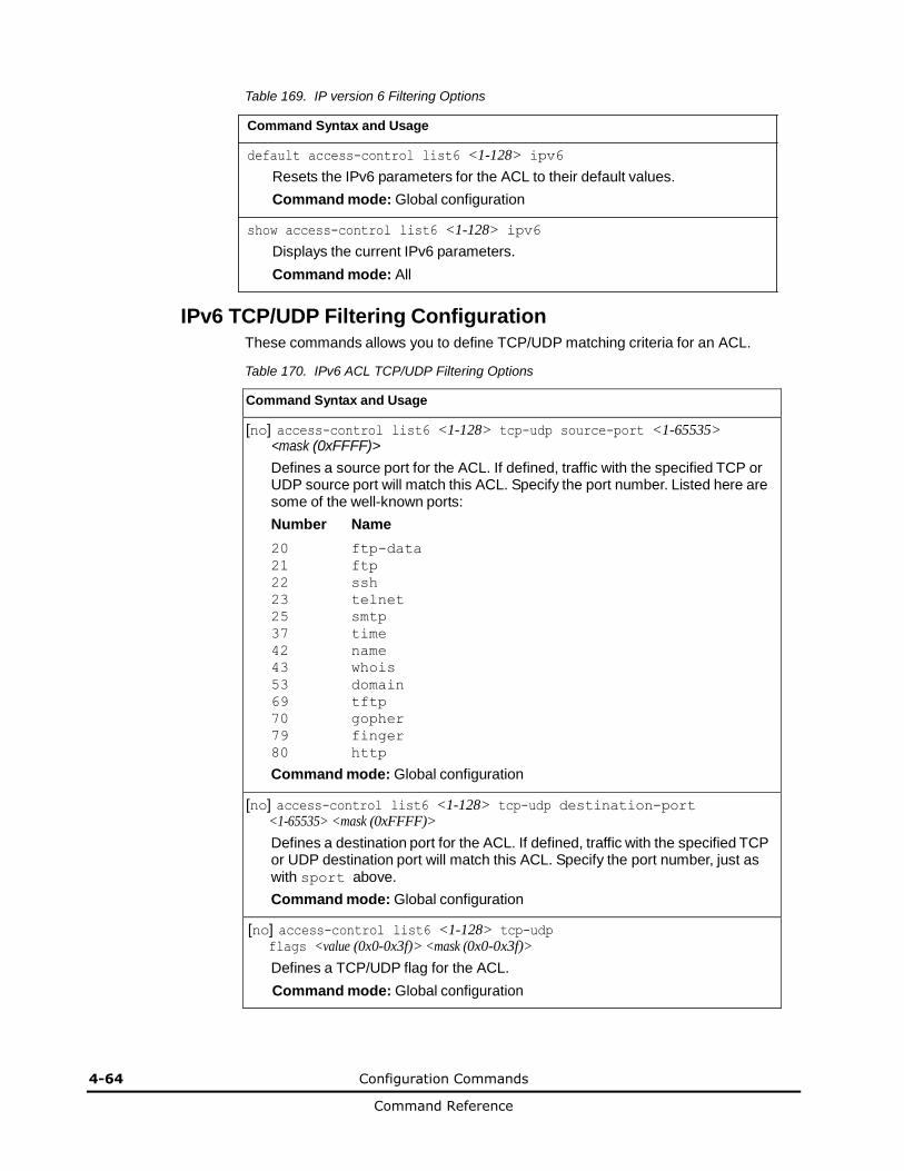
4-64 Configuration Commands
Command Reference
Table 169. IP version 6 Filtering Options
Command Syntax and Usage
default access-control list6 <1-128> ipv6
Resets the IPv6 parameters for the ACL to their default values.
Command mode: Global configuration
show access-control list6 <1-128> ipv6
Displays the current IPv6 parameters.
Command mode: All
IPv6 TCP/UDP Filtering Configuration
These commands allows you to define TCP/UDP matching criteria for an ACL.
Table 170. IPv6 ACL TCP/UDP Filtering Options
Command Syntax and Usage
[no] access-control list6 <1-128> tcp-udp source-port <1-65535> <mask (0xFFFF)>
Defines a source port for the ACL. If defined, traffic with the specified TCP or UDP source port will match this ACL. Specify the port number. Listed here are some of the well-known ports:
Number Name
20 ftp-data
21 ftp
22 ssh
23 telnet
25 smtp
37 time
42 name
43 whois
53 domain
69 tftp
70 gopher
79 finger
80 http
Command mode: Global configuration
[no] access-control list6 <1-128> tcp-udp destination-port <1-65535> <mask (0xFFFF)>
Defines a destination port for the ACL. If defined, traffic with the specified TCP or UDP destination port will match this ACL. Specify the port number, just as with sport above.
Command mode: Global configuration
[no] access-control list6 <1-128> tcp-udp flags <value (0x0-0x3f)> <mask (0x0-0x3f)>
Defines a TCP/UDP flag for the ACL.
Command mode: Global configuration
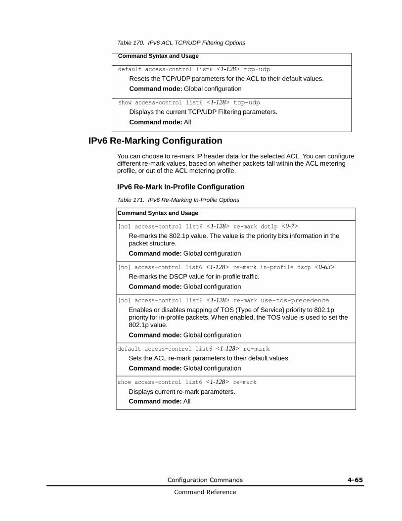
Configuration Commands 4-65
Command Reference
Table 170. IPv6 ACL TCP/UDP Filtering Options
Command Syntax and Usage
default access-control list6 <1-128> tcp-udp
Resets the TCP/UDP parameters for the ACL to their default values.
Command mode: Global configuration
show access-control list6 <1-128> tcp-udp
Displays the current TCP/UDP Filtering parameters.
Command mode: All
IPv6 Re-Marking Configuration
You can choose to re-mark IP header data for the selected ACL. You can configure different re-mark values, based on whether packets fall within the ACL metering profile, or out of the ACL metering profile.
IPv6 Re-Mark In-Profile Configuration
Table 171. IPv6 Re-Marking In-Profile Options
Command Syntax and Usage
[no] access-control list6 <1-128> re-mark dot1p <0-7>
Re-marks the 802.1p value. The value is the priority bits information in the packet structure.
Command mode: Global configuration
[no] access-control list6 <1-128> re-mark in-profile dscp <0-63>
Re-marks the DSCP value for in-profile traffic.
Command mode: Global configuration
[no] access-control list6 <1-128> re-mark use-tos-precedence
Enables or disables mapping of TOS (Type of Service) priority to 802.1p priority for in-profile packets. When enabled, the TOS value is used to set the 802.1p value.
Command mode: Global configuration
default access-control list6 <1-128> re-mark
Sets the ACL re-mark parameters to their default values.
Command mode: Global configuration
show access-control list6 <1-128> re-mark
Displays current re-mark parameters.
Command mode: All

4-66 Configuration Commands
Command Reference
IPv6 Metering Configuration
These commands define the Access Control profile for the selected ACL.
IPv6 Metering Configuration
Table 172. IPv6 Metering Options
Command Syntax and Usage
access-control list6 <1-640> meter committed-rate <64-40000000>
Configures the committed rate, in kilobits per second. The committed rate must be a multiple of 64.
Command mode: Global configuration
access-control list6 <1-640> meter maximum-burst-size <32-4096>
Configures the maximum burst size, in kilobits. Enter one of the following values for mbsize: 32, 64, 128, 256, 512, 1024, 2048, 4096.
Command mode: Global configuration
[no] access-control list6 <1-640> meter enable
Enables or disables ACL Metering.
Command mode: Global configuration
access-control list6 <1-640> meter action {drop|pass}
Configures the ACL Meter to either drop or pass out-of-profile traffic.
Command mode: Global configuration
default access-control list6 <1-640> meter
Sets the ACL meter configuration to its default values.
Command mode: Global configuration
no access-control list6 <1-640> meter
Deletes the selected ACL meter.
Command mode: Global configuration
show access-control list6 <1-640> meter
Displays current ACL Metering parameters.
Command mode: All
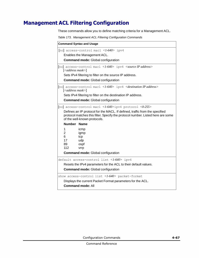
Configuration Commands 4-67
Command Reference
Management ACL Filtering Configuration
These commands allow you to define matching criteria for a Management ACL.
Table 173. Management ACL Filtering Configuration Commands
Command Syntax and Usage
[no] access-control macl <1-640> ipv4
Enables the Management ACL.
Command mode: Global configuration
[no] access-control macl <1-640> ipv4 <source IP address> [<address mask>]
Sets IPv4 filtering to filter on the source IP address.
Command mode: Global configuration
[no] access-control macl <1-640> ipv4 <destination IP address> [<address mask>]
Sets IPv4 filtering to filter on the destination IP address.
Command mode: Global configuration
[no] access-control macl <1-640>ipv4 protocol <0-255>
Defines an IP protocol for the MACL. If defined, traffic from the specified protocol matches this filter. Specify the protocol number. Listed here are some of the well-known protocols.
Number Name
1 icmp 2 igmp 6 tcp 17 udp 89 ospf 112 vrrp
Command mode: Global configuration
default access-control list <1-640> ipv4
Resets the IPv4 parameters for the ACL to their default values.
Command mode: Global configuration
show access-control list <1-640> packet-format
Displays the current Packet Format parameters for the ACL.
Command mode: All
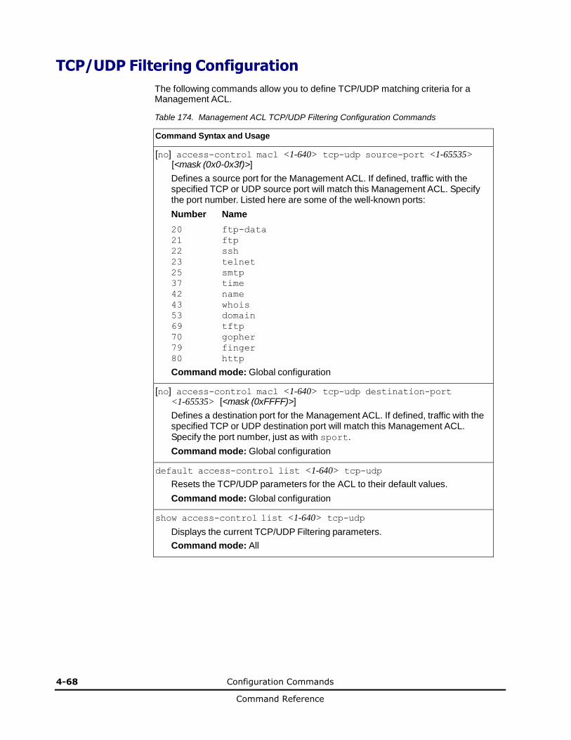
4-68 Configuration Commands
Command Reference
TCP/UDP Filtering Configuration
The following commands allow you to define TCP/UDP matching criteria for a Management ACL.
Table 174. Management ACL TCP/UDP Filtering Configuration Commands
Command Syntax and Usage
[no] access-control macl <1-640> tcp-udp source-port <1-65535> [<mask (0x0-0x3f)>]
Defines a source port for the Management ACL. If defined, traffic with the specified TCP or UDP source port will match this Management ACL. Specify the port number. Listed here are some of the well-known ports:
Number Name
20 ftp-data
21 ftp
22 ssh
23 telnet
25 smtp
37 time
42 name
43 whois
53 domain
69 tftp
70 gopher
79 finger
80 http
Command mode: Global configuration
[no] access-control macl <1-640> tcp-udp destination-port <1-65535> [<mask (0xFFFF)>]
Defines a destination port for the Management ACL. If defined, traffic with the specified TCP or UDP destination port will match this Management ACL. Specify the port number, just as with sport.
Command mode: Global configuration
default access-control list <1-640> tcp-udp
Resets the TCP/UDP parameters for the ACL to their default values.
Command mode: Global configuration
show access-control list <1-640> tcp-udp
Displays the current TCP/UDP Filtering parameters.
Command mode: All

Configuration Commands 4-69
Command Reference
VMAP Configuration
A VLAN Map is an Access Control List (ACL) that can be assigned to a VLAN or a VM group instead of a port. In a virtualized environment where Virtual Machines move between physical servers, VLAN Maps allow you to create traffic filtering and metering policies associated with a VM’s VLAN.
For more information about VLAN Map configuration commands, see “Access Control List Configuration” on page 4-58.
For more information about assigning VLAN Maps to a VLAN, see “VLAN Configuration” on page 4-115.
For more information about assigning VLAN Maps to a VM group, see “VM Group Configuration” on page 4-223.
Table 175 lists the general VMAP configuration commands.
Table 175. VMAP Configuration Commands
Command Syntax and Usage
[no] access-control vmap <1-128> egress-port <port alias or number>
Configures the VMAP to function on egress packets.
Command mode: Global configuration
access-control vmap <1-128> action {permit|deny| set-priority <0-7>}
Configures a filter action for packets that match the VMAP definitions. You can choose to permit (pass) or deny (drop) packets, or set the 802.1p priority level (0-7).
Command mode: Global configuration
[no] access-control vmap <1-128> ethernet source-mac-address <MAC address> <MAC mask>
Enables or disables filtering of VMAP statistics collection based on source MAC.
Command mode: Global configuration
[no] access-control vmap <1-128> ethernet destination-mac-address <MAC address> <MAC mask>
Enables or disables filtering of VMAP statistics collection based on destination MAC.
Command mode: Global configuration
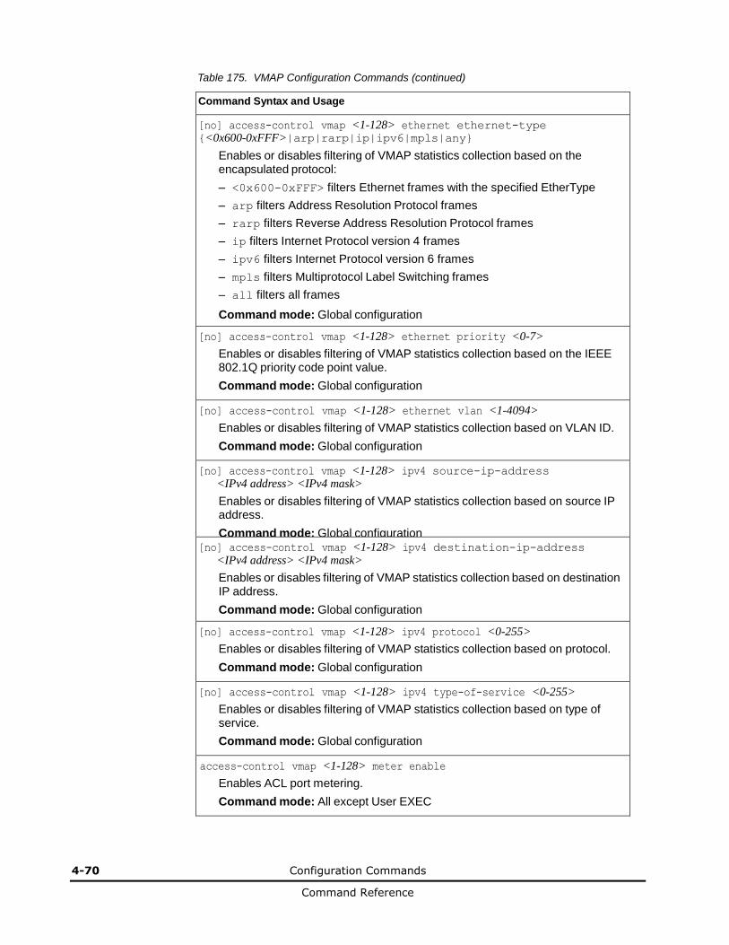
4-70 Configuration Commands
Command Reference
Table 175. VMAP Configuration Commands (continued)
Command Syntax and Usage
[no] access-control vmap <1-128> ethernet ethernet-type {<0x600-0xFFF>|arp|rarp|ip|ipv6|mpls|any}
Enables or disables filtering of VMAP statistics collection based on the encapsulated protocol:
– <0x600-0xFFF> filters Ethernet frames with the specified EtherType
– arp filters Address Resolution Protocol frames
– rarp filters Reverse Address Resolution Protocol frames
– ip filters Internet Protocol version 4 frames
– ipv6 filters Internet Protocol version 6 frames
– mpls filters Multiprotocol Label Switching frames
– all filters all frames
Command mode: Global configuration
[no] access-control vmap <1-128> ethernet priority <0-7>
Enables or disables filtering of VMAP statistics collection based on the IEEE 802.1Q priority code point value.
Command mode: Global configuration
[no] access-control vmap <1-128> ethernet vlan <1-4094>
Enables or disables filtering of VMAP statistics collection based on VLAN ID.
Command mode: Global configuration
[no] access-control vmap <1-128> ipv4 source-ip-address <IPv4 address> <IPv4 mask>
Enables or disables filtering of VMAP statistics collection based on source IP address.
Command mode: Global configuration [no] access-control vmap <1-128> ipv4 destination-ip-address
<IPv4 address> <IPv4 mask>
Enables or disables filtering of VMAP statistics collection based on destination IP address.
Command mode: Global configuration
[no] access-control vmap <1-128> ipv4 protocol <0-255>
Enables or disables filtering of VMAP statistics collection based on protocol.
Command mode: Global configuration
[no] access-control vmap <1-128> ipv4 type-of-service <0-255>
Enables or disables filtering of VMAP statistics collection based on type of service.
Command mode: Global configuration
access-control vmap <1-128> meter enable
Enables ACL port metering.
Command mode: All except User EXEC
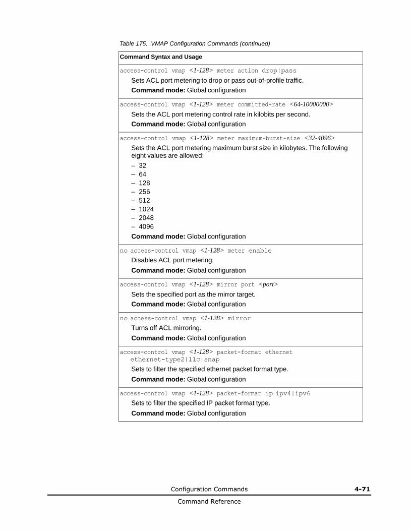
Configuration Commands 4-71
Command Reference
Table 175. VMAP Configuration Commands (continued)
Command Syntax and Usage
access-control vmap <1-128> meter action drop|pass
Sets ACL port metering to drop or pass out-of-profile traffic.
Command mode: Global configuration
access-control vmap <1-128> meter committed-rate <64-10000000>
Sets the ACL port metering control rate in kilobits per second.
Command mode: Global configuration
access-control vmap <1-128> meter maximum-burst-size <32-4096>
Sets the ACL port metering maximum burst size in kilobytes. The following eight values are allowed:
– 32
– 64
– 128
– 256
– 512
– 1024
– 2048
– 4096
Command mode: Global configuration
no access-control vmap <1-128> meter enable
Disables ACL port metering.
Command mode: Global configuration
access-control vmap <1-128> mirror port <port>
Sets the specified port as the mirror target.
Command mode: Global configuration
no access-control vmap <1-128> mirror
Turns off ACL mirroring.
Command mode: Global configuration
access-control vmap <1-128> packet-format ethernet ethernet-type2|llc|snap
Sets to filter the specified ethernet packet format type.
Command mode: Global configuration
access-control vmap <1-128> packet-format ip ipv4|ipv6
Sets to filter the specified IP packet format type.
Command mode: Global configuration
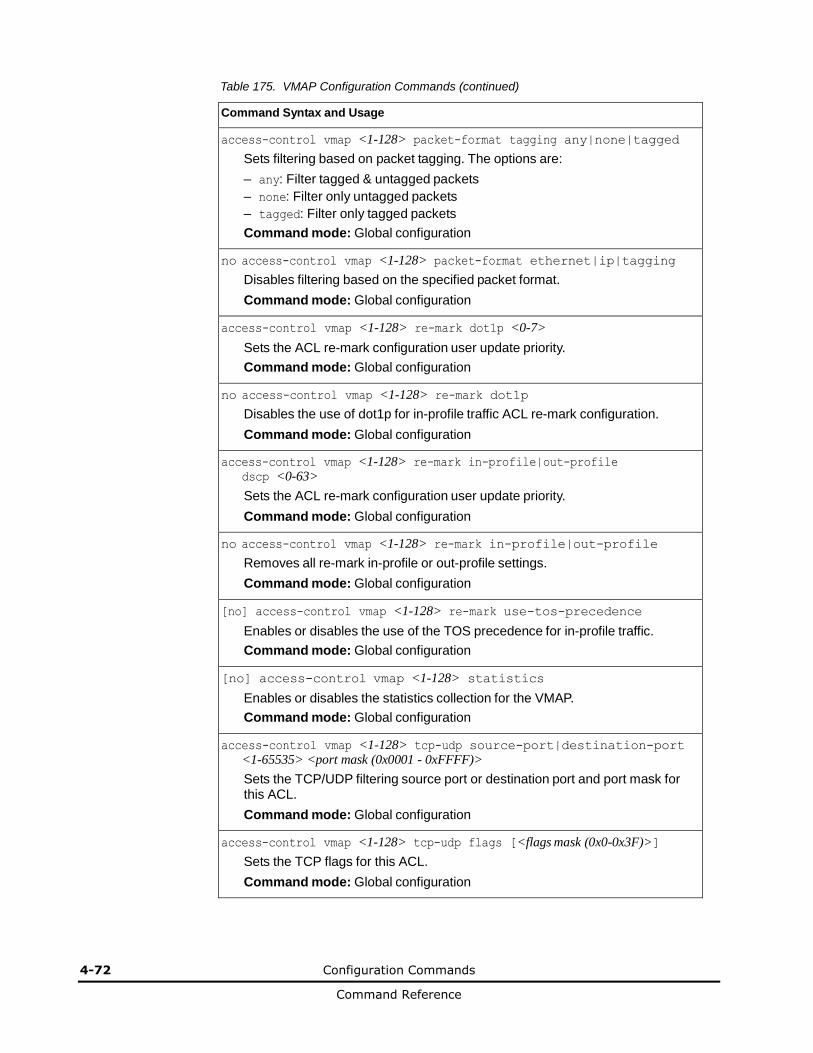
4-72 Configuration Commands
Command Reference
Table 175. VMAP Configuration Commands (continued)
Command Syntax and Usage
access-control vmap <1-128> packet-format tagging any|none|tagged
Sets filtering based on packet tagging. The options are:
– any: Filter tagged & untagged packets
– none: Filter only untagged packets
– tagged: Filter only tagged packets
Command mode: Global configuration
no access-control vmap <1-128> packet-format ethernet|ip|tagging
Disables filtering based on the specified packet format.
Command mode: Global configuration
access-control vmap <1-128> re-mark dot1p <0-7>
Sets the ACL re-mark configuration user update priority.
Command mode: Global configuration
no access-control vmap <1-128> re-mark dot1p
Disables the use of dot1p for in-profile traffic ACL re-mark configuration.
Command mode: Global configuration
access-control vmap <1-128> re-mark in-profile|out-profile dscp <0-63>
Sets the ACL re-mark configuration user update priority.
Command mode: Global configuration
no access-control vmap <1-128> re-mark in-profile|out-profile
Removes all re-mark in-profile or out-profile settings.
Command mode: Global configuration
[no] access-control vmap <1-128> re-mark use-tos-precedence
Enables or disables the use of the TOS precedence for in-profile traffic.
Command mode: Global configuration
[no] access-control vmap <1-128> statistics
Enables or disables the statistics collection for the VMAP.
Command mode: Global configuration
access-control vmap <1-128> tcp-udp source-port|destination-port <1-65535> <port mask (0x0001 - 0xFFFF)>
Sets the TCP/UDP filtering source port or destination port and port mask for this ACL.
Command mode: Global configuration
access-control vmap <1-128> tcp-udp flags [<flags mask (0x0-0x3F)>]
Sets the TCP flags for this ACL.
Command mode: Global configuration

Configuration Commands 4-73
Command Reference
Table 175. VMAP Configuration Commands (continued)
Command Syntax and Usage
no access-control vmap <1-128> tcp-udp
Removes TCP/UDP filtering for this ACL.
Command mode: Global configuration
default access-control vmap <1-128>
Resets the VMAP parameters to their default values.
Command mode: Global configuration
show access-control vmap <1-128>
Displays the current VMAP parameters.
Command mode: All
ACL Group Configuration
These commands allow you to compile one or more ACLs into an ACL group. Once you create an ACL group, you can assign the ACL group to one or more ports.
Table 176. ACL Group Configuration Commands
Command Syntax and Usage
access-control group <1-640> list <1-640>
Adds the selected ACL to the ACL group.
Command mode: Global configuration
no access-control group <1-640> list <1-640>
Removes the selected ACL from the ACL group.
Command mode: Global configuration
show access-control group <1-640>
Displays the current ACL group parameters.
Command mode: All
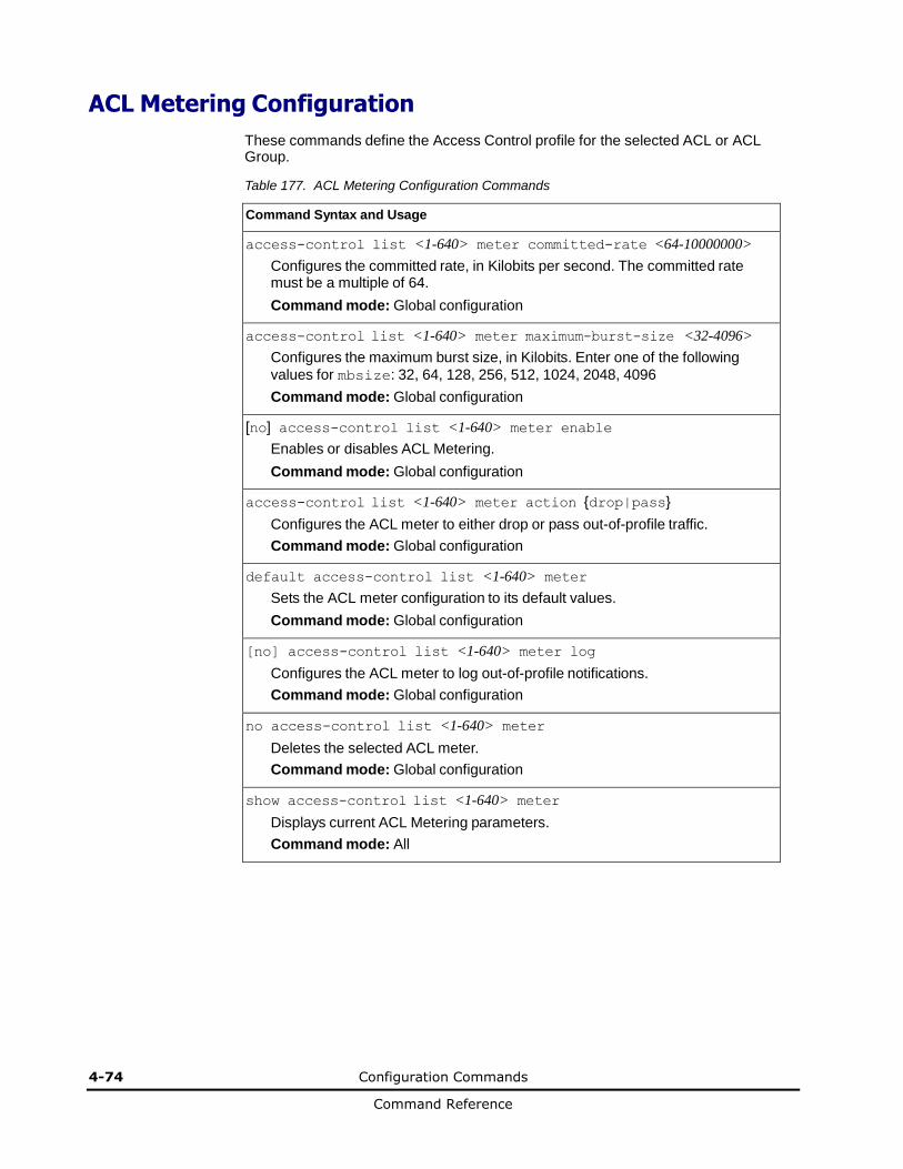
4-74 Configuration Commands
Command Reference
ACL Metering Configuration
These commands define the Access Control profile for the selected ACL or ACL Group.
Table 177. ACL Metering Configuration Commands
Command Syntax and Usage
access-control list <1-640> meter committed-rate <64-10000000>
Configures the committed rate, in Kilobits per second. The committed rate must be a multiple of 64.
Command mode: Global configuration
access-control list <1-640> meter maximum-burst-size <32-4096>
Configures the maximum burst size, in Kilobits. Enter one of the following
values for mbsize: 32, 64, 128, 256, 512, 1024, 2048, 4096
Command mode: Global configuration
[no] access-control list <1-640> meter enable
Enables or disables ACL Metering.
Command mode: Global configuration
access-control list <1-640> meter action {drop|pass}
Configures the ACL meter to either drop or pass out-of-profile traffic.
Command mode: Global configuration
default access-control list <1-640> meter
Sets the ACL meter configuration to its default values.
Command mode: Global configuration
[no] access-control list <1-640> meter log
Configures the ACL meter to log out-of-profile notifications.
Command mode: Global configuration
no access-control list <1-640> meter
Deletes the selected ACL meter.
Command mode: Global configuration
show access-control list <1-640> meter
Displays current ACL Metering parameters.
Command mode: All
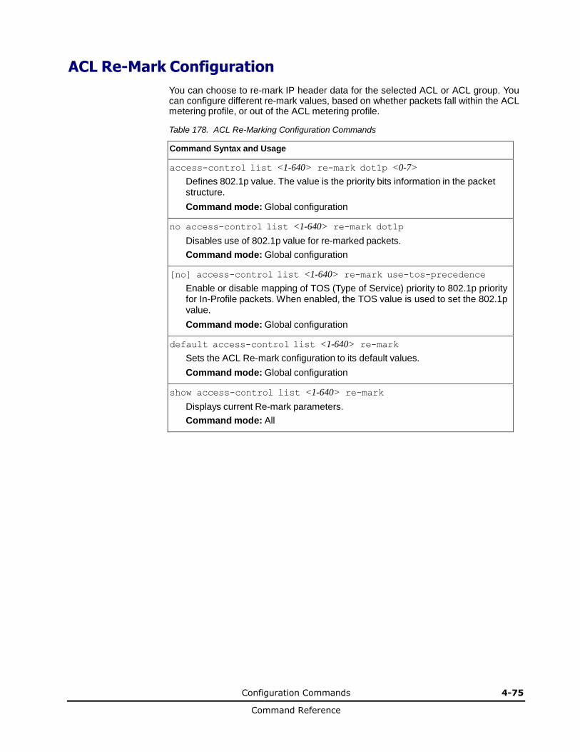
Configuration Commands 4-75
Command Reference
ACL Re-Mark Configuration
You can choose to re-mark IP header data for the selected ACL or ACL group. You can configure different re-mark values, based on whether packets fall within the ACL metering profile, or out of the ACL metering profile.
Table 178. ACL Re-Marking Configuration Commands
Command Syntax and Usage
access-control list <1-640> re-mark dot1p <0-7>
Defines 802.1p value. The value is the priority bits information in the packet structure.
Command mode: Global configuration
no access-control list <1-640> re-mark dot1p
Disables use of 802.1p value for re-marked packets.
Command mode: Global configuration
[no] access-control list <1-640> re-mark use-tos-precedence
Enable or disable mapping of TOS (Type of Service) priority to 802.1p priority for In-Profile packets. When enabled, the TOS value is used to set the 802.1p value.
Command mode: Global configuration
default access-control list <1-640> re-mark
Sets the ACL Re-mark configuration to its default values.
Command mode: Global configuration
show access-control list <1-640> re-mark
Displays current Re-mark parameters.
Command mode: All
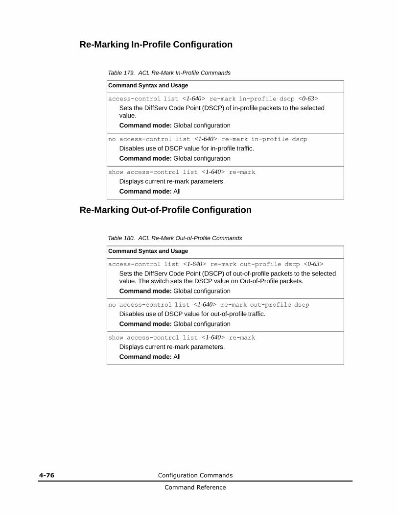
4-76 Configuration Commands
Command Reference
Re-Marking In-Profile Configuration
Table 179. ACL Re-Mark In-Profile Commands
Command Syntax and Usage
access-control list <1-640> re-mark in-profile dscp <0-63>
Sets the DiffServ Code Point (DSCP) of in-profile packets to the selected value.
Command mode: Global configuration
no access-control list <1-640> re-mark in-profile dscp
Disables use of DSCP value for in-profile traffic.
Command mode: Global configuration
show access-control list <1-640> re-mark
Displays current re-mark parameters.
Command mode: All
Re-Marking Out-of-Profile Configuration
Table 180. ACL Re-Mark Out-of-Profile Commands
Command Syntax and Usage
access-control list <1-640> re-mark out-profile dscp <0-63>
Sets the DiffServ Code Point (DSCP) of out-of-profile packets to the selected value. The switch sets the DSCP value on Out-of-Profile packets.
Command mode: Global configuration
no access-control list <1-640> re-mark out-profile dscp
Disables use of DSCP value for out-of-profile traffic.
Command mode: Global configuration
show access-control list <1-640> re-mark
Displays current re-mark parameters.
Command mode: All
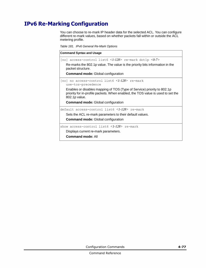
Configuration Commands 4-77
Command Reference
IPv6 Re-Marking Configuration
You can choose to re-mark IP header data for the selected ACL. You can configure different re-mark values, based on whether packets fall within or outside the ACL metering profile.
Table 181. IPv6 General Re-Mark Options
Command Syntax and Usage
[no] access-control list6 <1-128> re-mark dot1p <0-7>
Re-marks the 802.1p value. The value is the priority bits information in the packet structure.
Command mode: Global configuration
[no] no access-control list6 <1-128> re-mark use-tos-precedence
Enables or disables mapping of TOS (Type of Service) priority to 802.1p priority for in-profile packets. When enabled, the TOS value is used to set the 802.1p value.
Command mode: Global configuration
default access-control list6 <1-128> re-mark
Sets the ACL re-mark parameters to their default values.
Command mode: Global configuration
show access-control list6 <1-128> re-mark
Displays current re-mark parameters.
Command mode: All
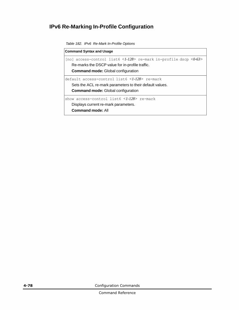
4-78 Configuration Commands
Command Reference
IPv6 Re-Marking In-Profile Configuration
Table 182. IPv6 Re-Mark In-Profile Options
Command Syntax and Usage
[no] access-control list6 <1-128> re-mark in-profile dscp <0-63>
Re-marks the DSCP value for in-profile traffic.
Command mode: Global configuration
default access-control list6 <1-128> re-mark
Sets the ACL re-mark parameters to their default values.
Command mode: Global configuration
show access-control list6 <1-128> re-mark
Displays current re-mark parameters.
Command mode: All
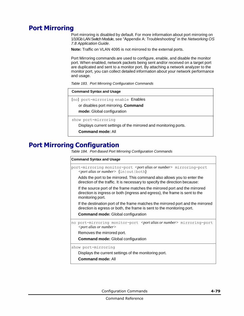
Configuration Commands 4-79
Command Reference
Port Mirroring Port mirroring is disabled by default. For more information about port mirroring on 1/10Gb LAN Switch Module, see “Appendix A: Troubleshooting” in the Networking OS 7.8 Application Guide.
Note: Traffic on VLAN 4095 is not mirrored to the external ports.
Port Mirroring commands are used to configure, enable, and disable the monitor port. When enabled, network packets being sent and/or received on a target port are duplicated and sent to a monitor port. By attaching a network analyzer to the monitor port, you can collect detailed information about your network performance and usage.
Table 183. Port Mirroring Configuration Commands
Command Syntax and Usage
[no] port-mirroring enable Enables
or disables port mirroring. Command
mode: Global configuration
show port-mirroring
Displays current settings of the mirrored and monitoring ports.
Command mode: All
Port Mirroring Configuration Table 184. Port-Based Port Mirroring Configuration Commands
Command Syntax and Usage
port-mirroring monitor-port <port alias or number> mirroring-port <port alias or number> {in|out|both}
Adds the port to be mirrored. This command also allows you to enter the direction of the traffic. It is necessary to specify the direction because:
If the source port of the frame matches the mirrored port and the mirrored direction is ingress or both (ingress and egress), the frame is sent to the monitoring port.
If the destination port of the frame matches the mirrored port and the mirrored direction is egress or both, the frame is sent to the monitoring port.
Command mode: Global configuration
no port-mirroring monitor-port <port alias or number> mirroring-port <port alias or number>
Removes the mirrored port.
Command mode: Global configuration
show port-mirroring
Displays the current settings of the monitoring port.
Command mode: All
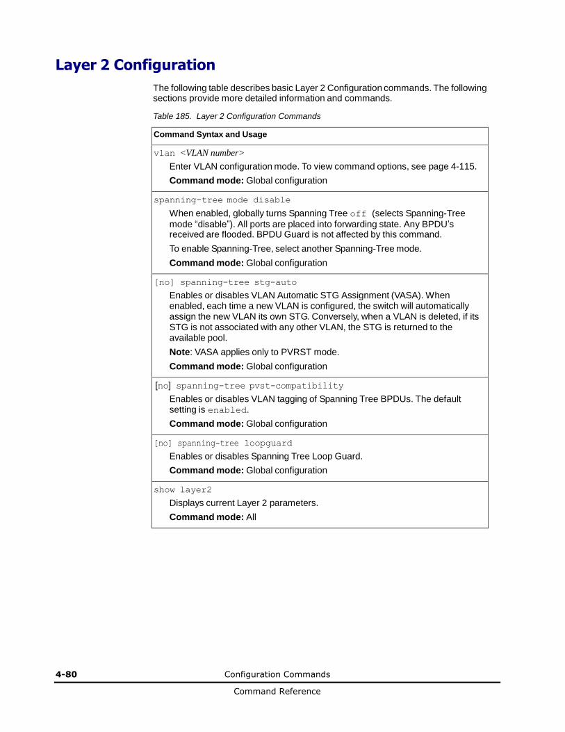
4-80 Configuration Commands
Command Reference
Layer 2 Configuration
The following table describes basic Layer 2 Configuration commands. The following sections provide more detailed information and commands.
Table 185. Layer 2 Configuration Commands
Command Syntax and Usage
vlan <VLAN number>
Enter VLAN configuration mode. To view command options, see page 4-115.
Command mode: Global configuration
spanning-tree mode disable
When enabled, globally turns Spanning Tree off (selects Spanning-Tree
mode “disable”). All ports are placed into forwarding state. Any BPDU’s received are flooded. BPDU Guard is not affected by this command.
To enable Spanning-Tree, select another Spanning-Tree mode.
Command mode: Global configuration
[no] spanning-tree stg-auto
Enables or disables VLAN Automatic STG Assignment (VASA). When enabled, each time a new VLAN is configured, the switch will automatically assign the new VLAN its own STG. Conversely, when a VLAN is deleted, if its STG is not associated with any other VLAN, the STG is returned to the available pool.
Note: VASA applies only to PVRST mode.
Command mode: Global configuration
[no] spanning-tree pvst-compatibility
Enables or disables VLAN tagging of Spanning Tree BPDUs. The default setting is enabled.
Command mode: Global configuration
[no] spanning-tree loopguard
Enables or disables Spanning Tree Loop Guard.
Command mode: Global configuration
show layer2
Displays current Layer 2 parameters.
Command mode: All
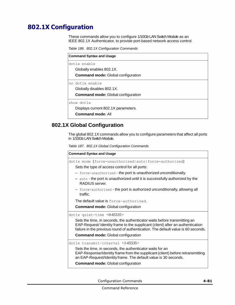
Configuration Commands 4-81
Command Reference
802.1X Configuration
These commands allow you to configure 1/10Gb LAN Switch Module as an IEEE 802.1X Authenticator, to provide port-based network access control.
Table 186. 802.1X Configuration Commands
Command Syntax and Usage
dot1x enable
Globally enables 802.1X.
Command mode: Global configuration
no dot1x enable
Globally disables 802.1X.
Command mode: Global configuration
show dot1x
Displays current 802.1X parameters.
Command mode: All
802.1X Global Configuration
The global 802.1X commands allow you to configure parameters that affect all ports in 1/10Gb LAN Switch Module.
Table 187. 802.1X Global Configuration Commands
Command Syntax and Usage
dot1x mode [force-unauthorized|auto|force-authorized]
Sets the type of access control for all ports:
– force-unauthorized - the port is unauthorized unconditionally.
– auto - the port is unauthorized until it is successfully authorized by the
RADIUS server.
– force-authorized - the port is authorized unconditionally, allowing all
traffic.
The default value is force-authorized.
Command mode: Global configuration
dot1x quiet-time <0-65535>
Sets the time, in seconds, the authenticator waits before transmitting an EAP-Request/ Identity frame to the supplicant (client) after an authentication failure in the previous round of authentication. The default value is 60 seconds.
Command mode: Global configuration
dot1x transmit-interval <1-65535>
Sets the time, in seconds, the authenticator waits for an EAP-Response/Identity frame from the supplicant (client) before retransmitting an EAP-Request/Identity frame. The default value is 30 seconds.
Command mode: Global configuration
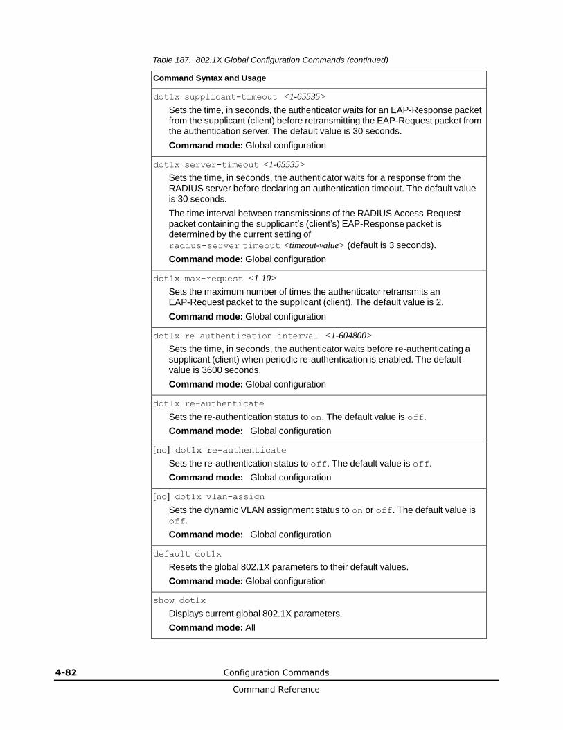
4-82 Configuration Commands
Command Reference
Table 187. 802.1X Global Configuration Commands (continued)
Command Syntax and Usage
dot1x supplicant-timeout <1-65535>
Sets the time, in seconds, the authenticator waits for an EAP-Response packet from the supplicant (client) before retransmitting the EAP-Request packet from the authentication server. The default value is 30 seconds.
Command mode: Global configuration
dot1x server-timeout <1-65535>
Sets the time, in seconds, the authenticator waits for a response from the RADIUS server before declaring an authentication timeout. The default value is 30 seconds.
The time interval between transmissions of the RADIUS Access-Request packet containing the supplicant’s (client’s) EAP-Response packet is determined by the current setting of
radius-server timeout <timeout-value> (default is 3 seconds).
Command mode: Global configuration
dot1x max-request <1-10>
Sets the maximum number of times the authenticator retransmits an EAP-Request packet to the supplicant (client). The default value is 2.
Command mode: Global configuration
dot1x re-authentication-interval <1-604800>
Sets the time, in seconds, the authenticator waits before re-authenticating a supplicant (client) when periodic re-authentication is enabled. The default value is 3600 seconds.
Command mode: Global configuration
dot1x re-authenticate
Sets the re-authentication status to on. The default value is off.
Command mode: Global configuration
[no] dot1x re-authenticate
Sets the re-authentication status to off. The default value is off.
Command mode: Global configuration
[no] dot1x vlan-assign
Sets the dynamic VLAN assignment status to on or off. The default value is off.
Command mode: Global configuration
default dot1x
Resets the global 802.1X parameters to their default values.
Command mode: Global configuration
show dot1x
Displays current global 802.1X parameters.
Command mode: All
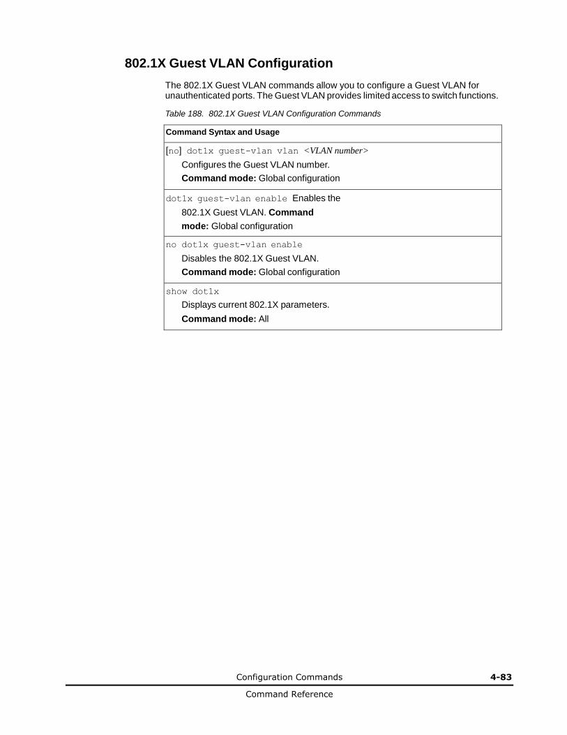
Configuration Commands 4-83
Command Reference
802.1X Guest VLAN Configuration
The 802.1X Guest VLAN commands allow you to configure a Guest VLAN for unauthenticated ports. The Guest VLAN provides limited access to switch functions.
Table 188. 802.1X Guest VLAN Configuration Commands
Command Syntax and Usage
[no] dot1x guest-vlan vlan <VLAN number>
Configures the Guest VLAN number.
Command mode: Global configuration
dot1x guest-vlan enable Enables the
802.1X Guest VLAN. Command
mode: Global configuration
no dot1x guest-vlan enable
Disables the 802.1X Guest VLAN.
Command mode: Global configuration
show dot1x
Displays current 802.1X parameters.
Command mode: All
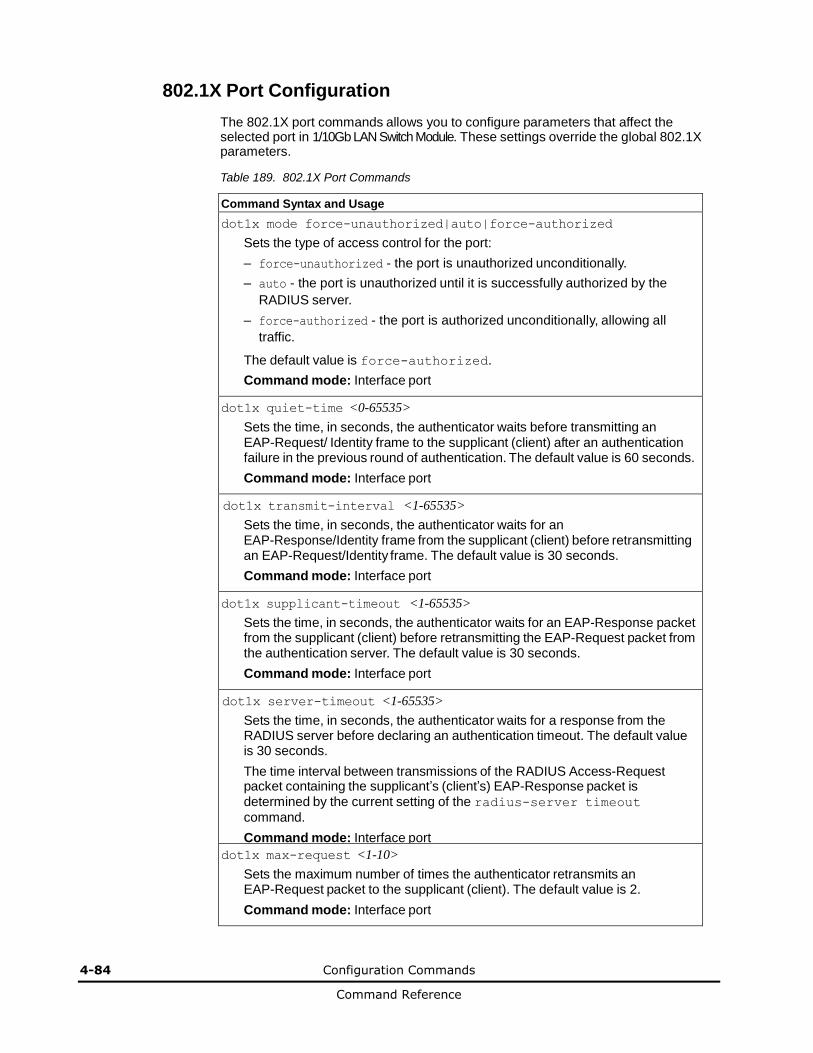
4-84 Configuration Commands
Command Reference
802.1X Port Configuration
The 802.1X port commands allows you to configure parameters that affect the selected port in 1/10Gb LAN Switch Module. These settings override the global 802.1X parameters.
Table 189. 802.1X Port Commands
Command Syntax and Usage
dot1x mode force-unauthorized|auto|force-authorized
Sets the type of access control for the port:
– force-unauthorized - the port is unauthorized unconditionally.
– auto - the port is unauthorized until it is successfully authorized by the
RADIUS server.
– force-authorized - the port is authorized unconditionally, allowing all
traffic.
The default value is force-authorized.
Command mode: Interface port
dot1x quiet-time <0-65535>
Sets the time, in seconds, the authenticator waits before transmitting an EAP-Request/ Identity frame to the supplicant (client) after an authentication failure in the previous round of authentication. The default value is 60 seconds.
Command mode: Interface port
dot1x transmit-interval <1-65535>
Sets the time, in seconds, the authenticator waits for an EAP-Response/Identity frame from the supplicant (client) before retransmitting an EAP-Request/Identity frame. The default value is 30 seconds.
Command mode: Interface port
dot1x supplicant-timeout <1-65535>
Sets the time, in seconds, the authenticator waits for an EAP-Response packet from the supplicant (client) before retransmitting the EAP-Request packet from the authentication server. The default value is 30 seconds.
Command mode: Interface port
dot1x server-timeout <1-65535>
Sets the time, in seconds, the authenticator waits for a response from the RADIUS server before declaring an authentication timeout. The default value is 30 seconds.
The time interval between transmissions of the RADIUS Access-Request packet containing the supplicant’s (client’s) EAP-Response packet is determined by the current setting of the radius-server timeout
command.
Command mode: Interface port
dot1x max-request <1-10>
Sets the maximum number of times the authenticator retransmits an EAP-Request packet to the supplicant (client). The default value is 2.
Command mode: Interface port
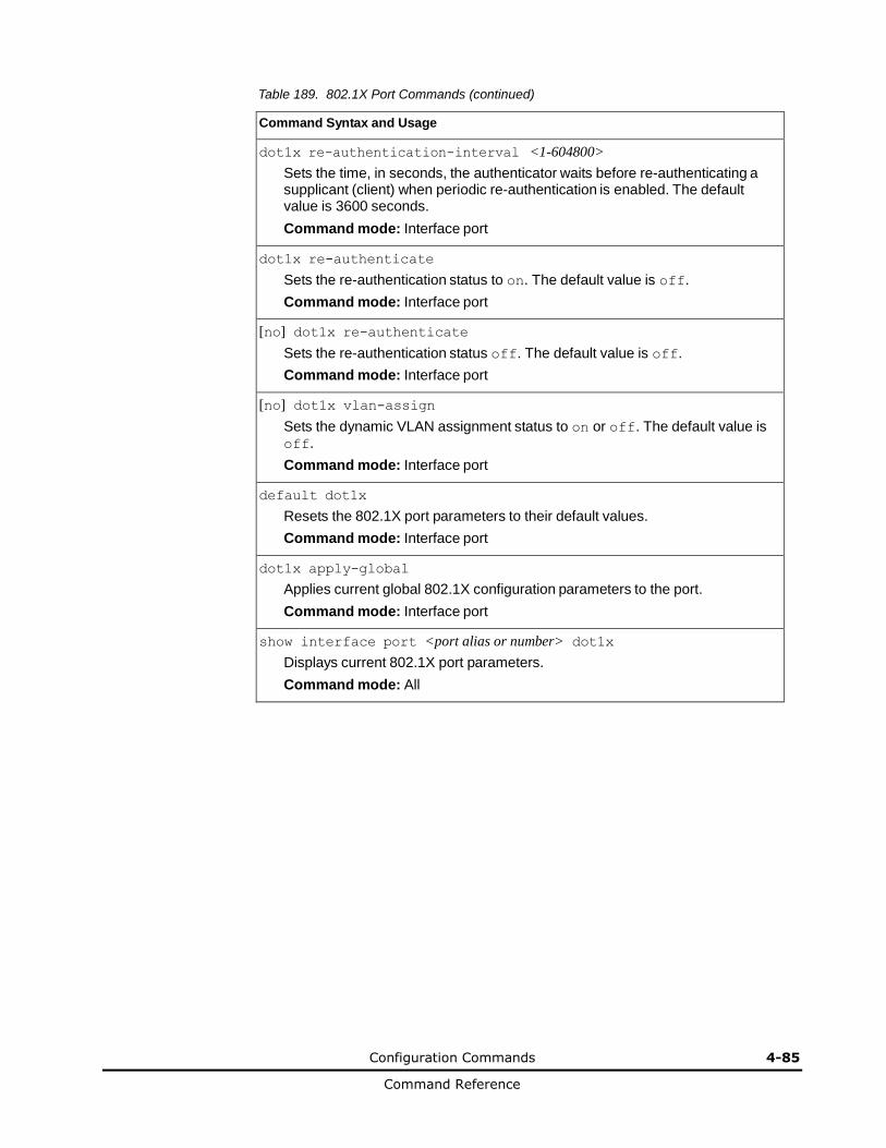
Configuration Commands 4-85
Command Reference
Table 189. 802.1X Port Commands (continued)
Command Syntax and Usage
dot1x re-authentication-interval <1-604800>
Sets the time, in seconds, the authenticator waits before re-authenticating a supplicant (client) when periodic re-authentication is enabled. The default value is 3600 seconds.
Command mode: Interface port
dot1x re-authenticate
Sets the re-authentication status to on. The default value is off.
Command mode: Interface port
[no] dot1x re-authenticate
Sets the re-authentication status off. The default value is off.
Command mode: Interface port
[no] dot1x vlan-assign
Sets the dynamic VLAN assignment status to on or off. The default value is off.
Command mode: Interface port
default dot1x
Resets the 802.1X port parameters to their default values.
Command mode: Interface port
dot1x apply-global
Applies current global 802.1X configuration parameters to the port.
Command mode: Interface port
show interface port <port alias or number> dot1x
Displays current 802.1X port parameters.
Command mode: All

4-86 Configuration Commands
Command Reference
Spanning Tree Configuration
Networking OS supports the IEEE 802.1D (2004) Rapid Spanning Tree Protocol (RSTP), the IEEE 802.1Q (2003) Multiple Spanning Tree Protocol (MSTP), and Per VLAN Rapid Spanning Tree Protocol (PVRST+). STP is used to prevent loops in the network topology. Up to 128 Spanning Tree Groups can be configured on the switch (STG 128 is reserved for management).
Note: When VRRP is used for active/active redundancy, STG must be enabled.
Table 190. Spanning Tree Configuration Options
Command Syntax and Usage
spanning-tree mode [disable|mst|pvrst|rstp]
Selects and enables Multiple Spanning Tree mode (mst), Per VLAN Rapid Spanning Tree mode (pvrst), or Rapid Spanning Tree mode (rstp).
The default mode is PVRST+.
When you select spanning-tree mode disable, the switch globally turns Spanning Tree off. All ports are placed into forwarding state. Any BPDU’s received are flooded. BPDU Guard is not affected by this command.
Command mode: Global configuration
[no] spanning-tree stg-auto
Enables or disables VLAN Automatic STG Assignment (VASA). When enabled, each time a new VLAN is configured, the switch will automatically assign the new VLAN its own STG. Conversely, when a VLAN is deleted, if its STG is not associated with any other VLAN, the STG is returned to the available pool.
Note: When using VASA, a maximum number of automatically assigned STGs is supported.
Note: VASA applies only to PVRST mode.
Command mode: Global configuration
[no] spanning-tree pvst-compatibility
Enables or disables VLAN tagging of Spanning Tree BPDUs. The default setting is enabled.
Command mode: Global configuration
[no] spanning-tree portfast
Enables or disables this port as portfast or edge port. An edge port is not connected to a bridge, and can begin forwarding traffic as soon as the link is
up. Configure server ports as edge ports (enabled).
Note: After you configure the port as an edge port, you must disable the port and then re-enable the port for the change to take effect.
Command mode: Interface port/Interface portchannel
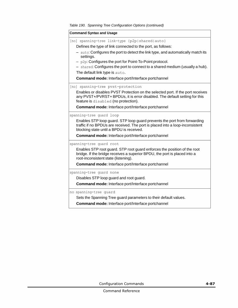
Configuration Commands 4-87
Command Reference
Table 190. Spanning Tree Configuration Options (continued)
Command Syntax and Usage
[no] spanning-tree link-type {p2p|shared|auto}
Defines the type of link connected to the port, as follows:
– auto: Configures the port to detect the link type, and automatically match its settings.
– p2p: Configures the port for Point-To-Point protocol.
– shared: Configures the port to connect to a shared medium (usually a hub).
The default link type is auto.
Command mode: Interface port/Interface portchannel
[no] spanning-tree pvst-protection
Enables or disables PVST Protection on the selected port. If the port receives any PVST+/PVRST+ BPDUs, it is error disabled. The default setting for this
feature is disabled (no protection).
Command mode: Interface port/Interface portchannel
spanning-tree guard loop
Enables STP loop guard. STP loop guard prevents the port from forwarding traffic if no BPDUs are received. The port is placed into a loop-inconsistent blocking state until a BPDU is received.
Command mode: Interface port/Interface portchannel
spanning-tree guard root
Enables STP root guard. STP root guard enforces the position of the root bridge. If the bridge receives a superior BPDU, the port is placed into a root-inconsistent state (listening).
Command mode: Interface port/Interface portchannel
spanning-tree guard none
Disables STP loop guard and root guard.
Command mode: Interface port/Interface portchannel
no spanning-tree guard
Sets the Spanning Tree guard parameters to their default values.
Command mode: Interface port/Interface portchannel

4-88 Configuration Commands
Command Reference
Table 190. Spanning Tree Configuration Options (continued)
Command Syntax and Usage
show spanning-tree
Displays Spanning Tree information, including the status (on or off), Spanning Tree mode (RSTP, PVRST, or MSTP), and VLAN membership.
In addition to seeing if STG is enabled or disabled, you can view the following STG bridge information:
– Priority
– Hello interval
– Maximum age value
– Forwarding delay
– Aging time
You can also see the following port-specific STG information:
– Port alias and priority
– Cost
– State
Command mode: All
show spanning-tree root
Displays the Spanning Tree configuration on the root bridge for each STP instance. For details, see page 2-19.
Command mode: All
show spanning-tree blockedports
Lists the ports blocked by each STP instance.
Command mode: All
show spanning-tree [vlan <VLAN ID>] bridge
Displays Spanning Tree bridge information. For details, see page 2-19.
Command mode: All
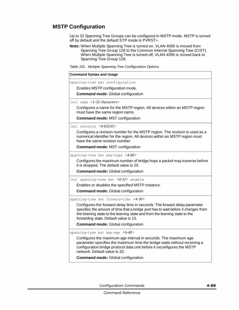
Configuration Commands 4-89
Command Reference
MSTP Configuration
Up to 32 Spanning Tree Groups can be configured in MSTP mode. MSTP is turned off by default and the default STP mode is PVRST+.
Note: When Multiple Spanning Tree is turned on, VLAN 4095 is moved from Spanning Tree Group 128 to the Common Internal Spanning Tree (CIST). When Multiple Spanning Tree is turned off, VLAN 4095 is moved back to Spanning Tree Group 128.
Table 191. Multiple Spanning Tree Configuration Options
Command Syntax and Usage
spanning-tree mst configuration
Enables MSTP configuration mode.
Command mode: Global configuration
[no] name <1-32 characters>
Configures a name for the MSTP region. All devices within an MSTP region must have the same region name.
Command mode: MST configuration
[no] revision <0-65535>
Configures a revision number for the MSTP region. The revision is used as a numerical identifier for the region. All devices within an MSTP region must have the same revision number.
Command mode: MST configuration
spanning-tree mst max-hops <4-60>
Configures the maximum number of bridge hops a packet may traverse before it is dropped. The default value is 20.
Command mode: Global configuration
[no] spanning-tree mst <0-32> enable
Enables or disables the specified MSTP instance.
Command mode: Global configuration
spanning-tree mst forward-time <4-30>
Configures the forward delay time in seconds. The forward delay parameter specifies the amount of time that a bridge port has to wait before it changes from the listening state to the learning state and from the learning state to the forwarding state. Default value is 15.
Command mode: Global configuration
spanning-tree mst max-age <6-40>
Configures the maximum age interval in seconds. The maximum age parameter specifies the maximum time the bridge waits without receiving a configuration bridge protocol data unit before it reconfigures the MSTP network. Default value is 20.
Command mode: Global configuration

4-90 Configuration Commands
Command Reference
Table 191. Multiple Spanning Tree Configuration Options (continued)
Command Syntax and Usage
default spanning-tree mst <0-32>
Restores the Spanning Tree instance to its default configuration.
Command mode: Global configuration
instance <0-32> vlan <VLAN numbers>
Map the specified VLANs to the Spanning Tree instance. If a VLAN does not exist, it will be created automatically, but it will not be enabled by default.
Command mode: MST configuration
no instance <1-32> vlan <VLAN numbers>
Remove the specified VLAN from the Spanning Tree instance.
Command mode: MST configuration
spanning-tree mst <0-32> priority <0-65535>
Configures the CIST bridge priority for the specified MSTP instance. The bridge priority parameter controls which bridge on the network is the MSTP root bridge. To make this switch the root bridge, configure the bridge priority lower than all other switches and bridges on your network. The lower the value, the higher the bridge priority. The range is 0 to 65535, in steps of 4096 (0, 4096, 8192...); the default value is 61440.
Command mode: Global configuration
no spanning-tree mst configuration
Returns the MST region to its default values: no VLAN is mapped to any MST
instance. Revision number is reset to 0.
Command mode: Global configuration
show spanning-tree mst <0-32> information
Displays the current CIST configuration for the specified instance.
Command mode: All
show spanning-tree mst configuration
Displays the current MSTP settings.
Command mode: All
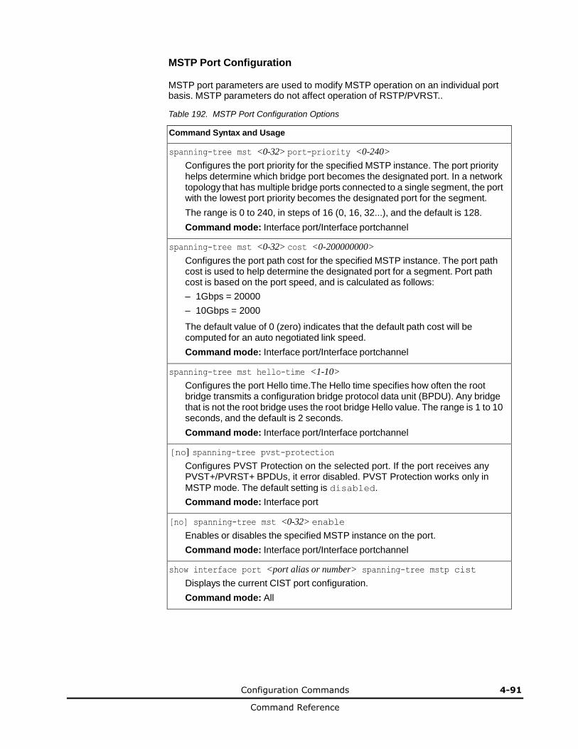
Configuration Commands 4-91
Command Reference
MSTP Port Configuration
MSTP port parameters are used to modify MSTP operation on an individual port basis. MSTP parameters do not affect operation of RSTP/PVRST..
Table 192. MSTP Port Configuration Options
Command Syntax and Usage
spanning-tree mst <0-32> port-priority <0-240>
Configures the port priority for the specified MSTP instance. The port priority helps determine which bridge port becomes the designated port. In a network topology that has multiple bridge ports connected to a single segment, the port with the lowest port priority becomes the designated port for the segment.
The range is 0 to 240, in steps of 16 (0, 16, 32...), and the default is 128.
Command mode: Interface port/Interface portchannel
spanning-tree mst <0-32> cost <0-200000000>
Configures the port path cost for the specified MSTP instance. The port path cost is used to help determine the designated port for a segment. Port path cost is based on the port speed, and is calculated as follows:
– 1Gbps = 20000
– 10Gbps = 2000
The default value of 0 (zero) indicates that the default path cost will be computed for an auto negotiated link speed.
Command mode: Interface port/Interface portchannel
spanning-tree mst hello-time <1-10>
Configures the port Hello time.The Hello time specifies how often the root bridge transmits a configuration bridge protocol data unit (BPDU). Any bridge that is not the root bridge uses the root bridge Hello value. The range is 1 to 10 seconds, and the default is 2 seconds.
Command mode: Interface port/Interface portchannel
[no] spanning-tree pvst-protection
Configures PVST Protection on the selected port. If the port receives any PVST+/PVRST+ BPDUs, it error disabled. PVST Protection works only in
MSTP mode. The default setting is disabled.
Command mode: Interface port
[no] spanning-tree mst <0-32> enable
Enables or disables the specified MSTP instance on the port.
Command mode: Interface port/Interface portchannel
show interface port <port alias or number> spanning-tree mstp cist
Displays the current CIST port configuration.
Command mode: All
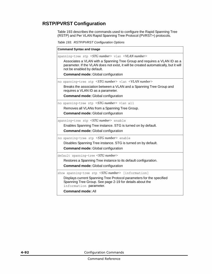
4-92 Configuration Commands
Command Reference
RSTP/PVRST Configuration
Table 193 describes the commands used to configure the Rapid Spanning Tree (RSTP) and Per VLAN Rapid Spanning Tree Protocol (PVRST+) protocols.
Table 193. RSTP/PVRST Configuration Options
Command Syntax and Usage
spanning-tree stp <STG number> vlan <VLAN number>
Associates a VLAN with a Spanning Tree Group and requires a VLAN ID as a parameter. If the VLAN does not exist, it will be created automatically, but it will not be enabled by default.
Command mode: Global configuration
no spanning-tree stp <STG number> vlan <VLAN number>
Breaks the association between a VLAN and a Spanning Tree Group and requires a VLAN ID as a parameter.
Command mode: Global configuration
no spanning-tree stp <STG number> vlan all
Removes all VLANs from a Spanning Tree Group.
Command mode: Global configuration
spanning-tree stp <STG number> enable
Enables Spanning Tree instance. STG is turned on by default.
Command mode: Global configuration
no spanning-tree stp <STG number> enable
Disables Spanning Tree instance. STG is turned on by default.
Command mode: Global configuration
default spanning-tree <STG number>
Restores a Spanning Tree instance to its default configuration.
Command mode: Global configuration
show spanning-tree stp <STG number> [information]
Displays current Spanning Tree Protocol parameters for the specified Spanning Tree Group. See page 2-19 for details about the information parameter.
Command mode: All
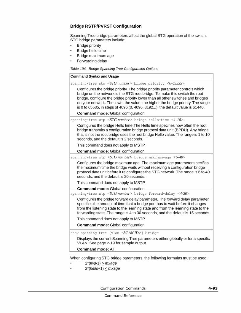
Configuration Commands 4-93
Command Reference
Bridge RSTP/PVRST Configuration
Spanning Tree bridge parameters affect the global STG operation of the switch. STG bridge parameters include:
• Bridge priority
• Bridge hello time
• Bridge maximum age
• Forwarding delay
Table 194. Bridge Spanning Tree Configuration Options
Command Syntax and Usage
spanning-tree stp <STG number> bridge priority <0-65535>
Configures the bridge priority. The bridge priority parameter controls which bridge on the network is the STG root bridge. To make this switch the root bridge, configure the bridge priority lower than all other switches and bridges on your network. The lower the value, the higher the bridge priority. The range is 0 to 65535, in steps of 4096 (0, 4096, 8192...); the default value is 61440.
Command mode: Global configuration
spanning-tree stp <STG number> bridge hello-time <1-10>
Configures the bridge Hello time.The Hello time specifies how often the root bridge transmits a configuration bridge protocol data unit (BPDU). Any bridge that is not the root bridge uses the root bridge Hello value. The range is 1 to 10 seconds, and the default is 2 seconds.
This command does not apply to MSTP.
Command mode: Global configuration
spanning-tree stp <STG number> bridge maximum-age <6-40>
Configures the bridge maximum age. The maximum age parameter specifies the maximum time the bridge waits without receiving a configuration bridge protocol data unit before it re configures the STG network. The range is 6 to 40 seconds, and the default is 20 seconds.
This command does not apply to MSTP.
Command mode: Global configuration
spanning-tree stp <STG number> bridge forward-delay <4-30>
Configures the bridge forward delay parameter. The forward delay parameter specifies the amount of time that a bridge port has to wait before it changes from the listening state to the learning state and from the learning state to the forwarding state. The range is 4 to 30 seconds, and the default is 15 seconds.
This command does not apply to MSTP
Command mode: Global configuration
show spanning-tree [vlan <VLAN ID>] bridge
Displays the current Spanning Tree parameters either globally or for a specific VLAN. See page 2-19 for sample output.
Command mode: All
When configuring STG bridge parameters, the following formulas must be used:
• 2*(fwd-1) > mxage
• 2*(hello+1) < mxage
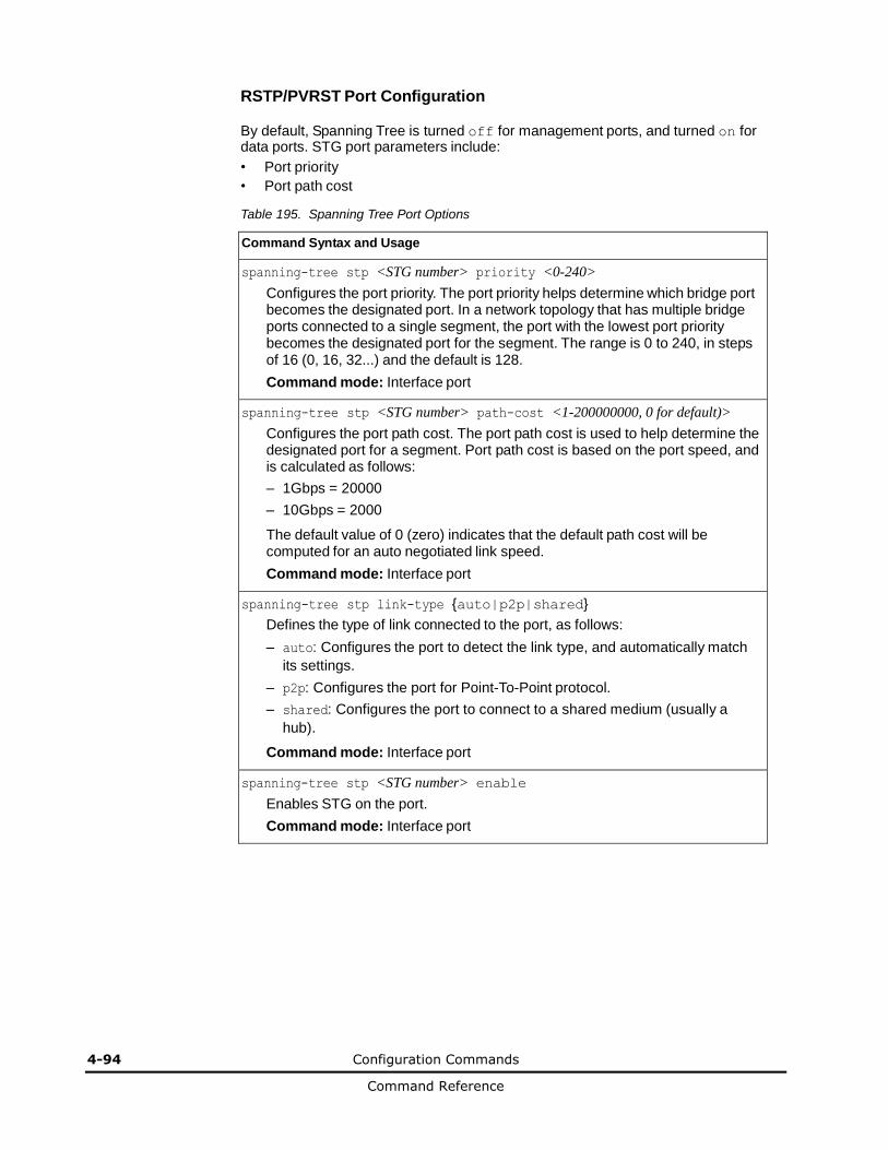
4-94 Configuration Commands
Command Reference
RSTP/PVRST Port Configuration
By default, Spanning Tree is turned off for management ports, and turned on for data ports. STG port parameters include:
• Port priority
• Port path cost
Table 195. Spanning Tree Port Options
Command Syntax and Usage
spanning-tree stp <STG number> priority <0-240>
Configures the port priority. The port priority helps determine which bridge port becomes the designated port. In a network topology that has multiple bridge ports connected to a single segment, the port with the lowest port priority becomes the designated port for the segment. The range is 0 to 240, in steps of 16 (0, 16, 32...) and the default is 128.
Command mode: Interface port
spanning-tree stp <STG number> path-cost <1-200000000, 0 for default)>
Configures the port path cost. The port path cost is used to help determine the designated port for a segment. Port path cost is based on the port speed, and is calculated as follows:
– 1Gbps = 20000
– 10Gbps = 2000
The default value of 0 (zero) indicates that the default path cost will be computed for an auto negotiated link speed.
Command mode: Interface port
spanning-tree stp link-type {auto|p2p|shared}
Defines the type of link connected to the port, as follows:
– auto: Configures the port to detect the link type, and automatically match
its settings.
– p2p: Configures the port for Point-To-Point protocol.
– shared: Configures the port to connect to a shared medium (usually a
hub).
Command mode: Interface port
spanning-tree stp <STG number> enable
Enables STG on the port.
Command mode: Interface port
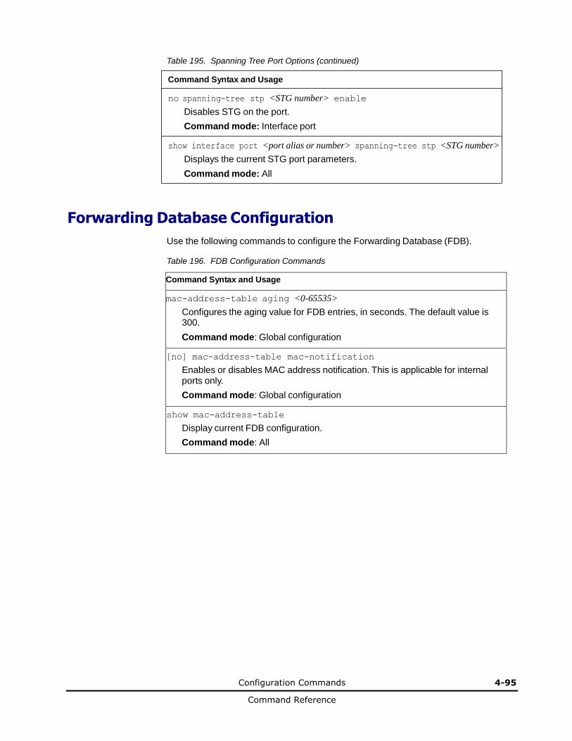
Configuration Commands 4-95
Command Reference
Table 195. Spanning Tree Port Options (continued)
Command Syntax and Usage
no spanning-tree stp <STG number> enable
Disables STG on the port.
Command mode: Interface port
show interface port <port alias or number> spanning-tree stp <STG number>
Displays the current STG port parameters.
Command mode: All
Forwarding Database Configuration
Use the following commands to configure the Forwarding Database (FDB).
Table 196. FDB Configuration Commands
Command Syntax and Usage
mac-address-table aging <0-65535>
Configures the aging value for FDB entries, in seconds. The default value is 300.
Command mode: Global configuration
[no] mac-address-table mac-notification
Enables or disables MAC address notification. This is applicable for internal ports only.
Command mode: Global configuration
show mac-address-table
Display current FDB configuration.
Command mode: All
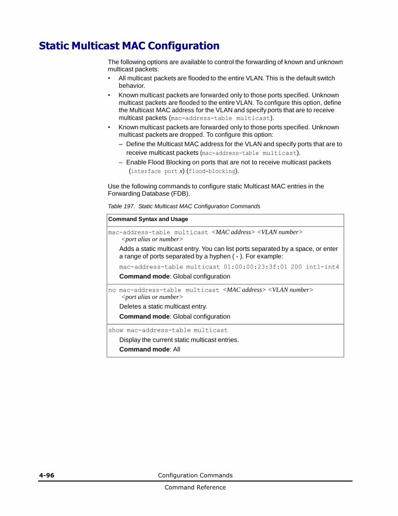
4-96 Configuration Commands
Command Reference
Static Multicast MAC Configuration
The following options are available to control the forwarding of known and unknown multicast packets:
• All multicast packets are flooded to the entire VLAN. This is the default switch behavior.
• Known multicast packets are forwarded only to those ports specified. Unknown multicast packets are flooded to the entire VLAN. To configure this option, define the Multicast MAC address for the VLAN and specify ports that are to receive
multicast packets (mac-address-table multicast).
• Known multicast packets are forwarded only to those ports specified. Unknown multicast packets are dropped. To configure this option:
– Define the Multicast MAC address for the VLAN and specify ports that are to
receive multicast packets (mac-address-table multicast).
– Enable Flood Blocking on ports that are not to receive multicast packets
(interface port x) (flood-blocking).
Use the following commands to configure static Multicast MAC entries in the Forwarding Database (FDB).
Table 197. Static Multicast MAC Configuration Commands
Command Syntax and Usage
mac-address-table multicast <MAC address> <VLAN number> <port alias or number>
Adds a static multicast entry. You can list ports separated by a space, or enter a range of ports separated by a hyphen ( - ). For example:
mac-address-table multicast 01:00:00:23:3f:01 200 int1-int4
Command mode: Global configuration
no mac-address-table multicast <MAC address> <VLAN number> <port alias or number>
Deletes a static multicast entry.
Command mode: Global configuration
show mac-address-table multicast
Display the current static multicast entries.
Command mode: All
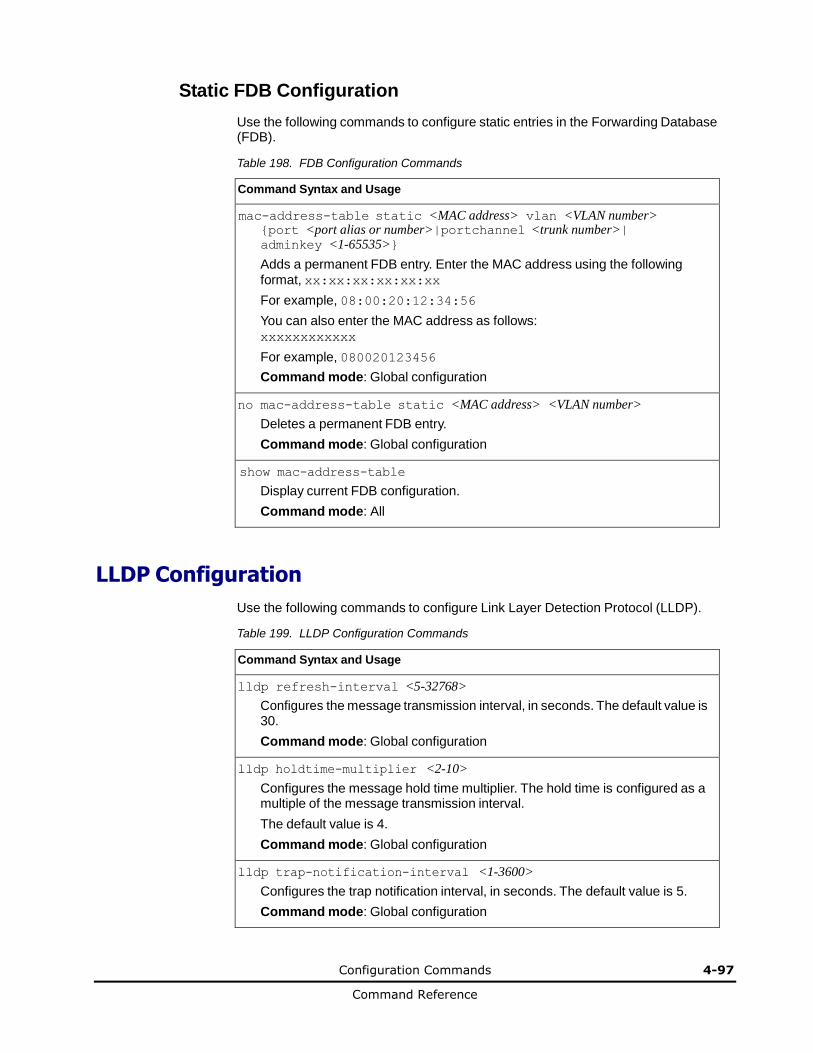
Configuration Commands 4-97
Command Reference
Static FDB Configuration
Use the following commands to configure static entries in the Forwarding Database (FDB).
Table 198. FDB Configuration Commands
Command Syntax and Usage
mac-address-table static <MAC address> vlan <VLAN number> {port <port alias or number>|portchannel <trunk number>| adminkey <1-65535>}
Adds a permanent FDB entry. Enter the MAC address using the following
format, xx:xx:xx:xx:xx:xx
For example, 08:00:20:12:34:56
You can also enter the MAC address as follows: xxxxxxxxxxxx
For example, 080020123456
Command mode: Global configuration
no mac-address-table static <MAC address> <VLAN number>
Deletes a permanent FDB entry.
Command mode: Global configuration
show mac-address-table
Display current FDB configuration.
Command mode: All
LLDP Configuration
Use the following commands to configure Link Layer Detection Protocol (LLDP).
Table 199. LLDP Configuration Commands
Command Syntax and Usage
lldp refresh-interval <5-32768>
Configures the message transmission interval, in seconds. The default value is 30.
Command mode: Global configuration
lldp holdtime-multiplier <2-10>
Configures the message hold time multiplier. The hold time is configured as a multiple of the message transmission interval.
The default value is 4.
Command mode: Global configuration
lldp trap-notification-interval <1-3600>
Configures the trap notification interval, in seconds. The default value is 5.
Command mode: Global configuration
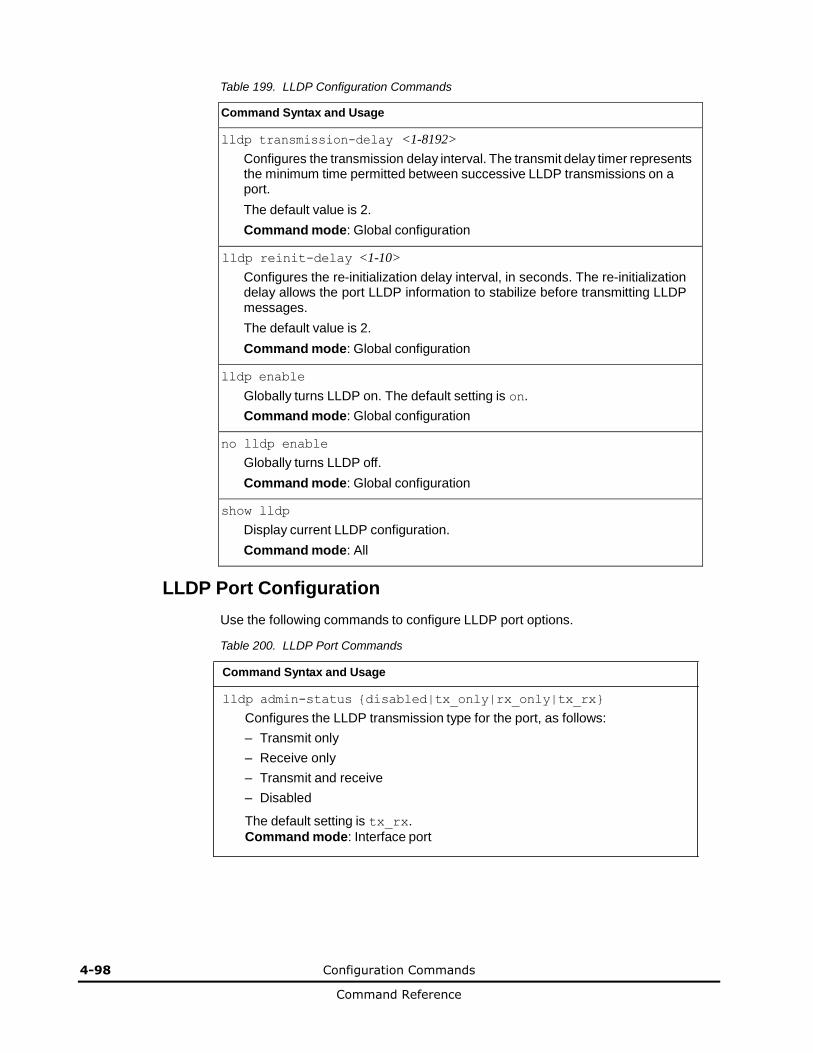
4-98 Configuration Commands
Command Reference
Table 199. LLDP Configuration Commands
Command Syntax and Usage
lldp transmission-delay <1-8192>
Configures the transmission delay interval. The transmit delay timer represents the minimum time permitted between successive LLDP transmissions on a port.
The default value is 2.
Command mode: Global configuration
lldp reinit-delay <1-10>
Configures the re-initialization delay interval, in seconds. The re-initialization delay allows the port LLDP information to stabilize before transmitting LLDP messages.
The default value is 2.
Command mode: Global configuration
lldp enable
Globally turns LLDP on. The default setting is on.
Command mode: Global configuration
no lldp enable
Globally turns LLDP off.
Command mode: Global configuration
show lldp
Display current LLDP configuration.
Command mode: All
LLDP Port Configuration
Use the following commands to configure LLDP port options.
Table 200. LLDP Port Commands
Command Syntax and Usage
lldp admin-status {disabled|tx_only|rx_only|tx_rx}
Configures the LLDP transmission type for the port, as follows:
– Transmit only
– Receive only
– Transmit and receive
– Disabled
The default setting is tx_rx.
Command mode: Interface port
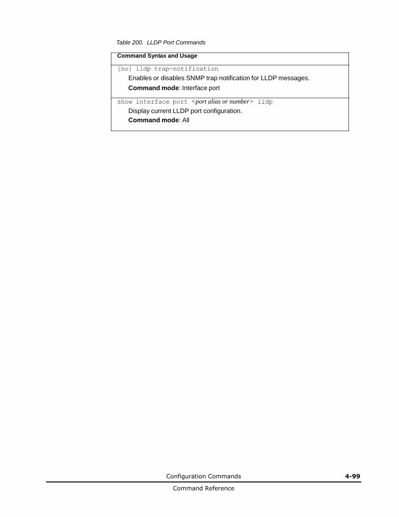
Configuration Commands 4-99
Command Reference
Table 200. LLDP Port Commands
Command Syntax and Usage
[no] lldp trap-notification
Enables or disables SNMP trap notification for LLDP messages.
Command mode: Interface port
show interface port <port alias or number> lldp
Display current LLDP port configuration.
Command mode: All
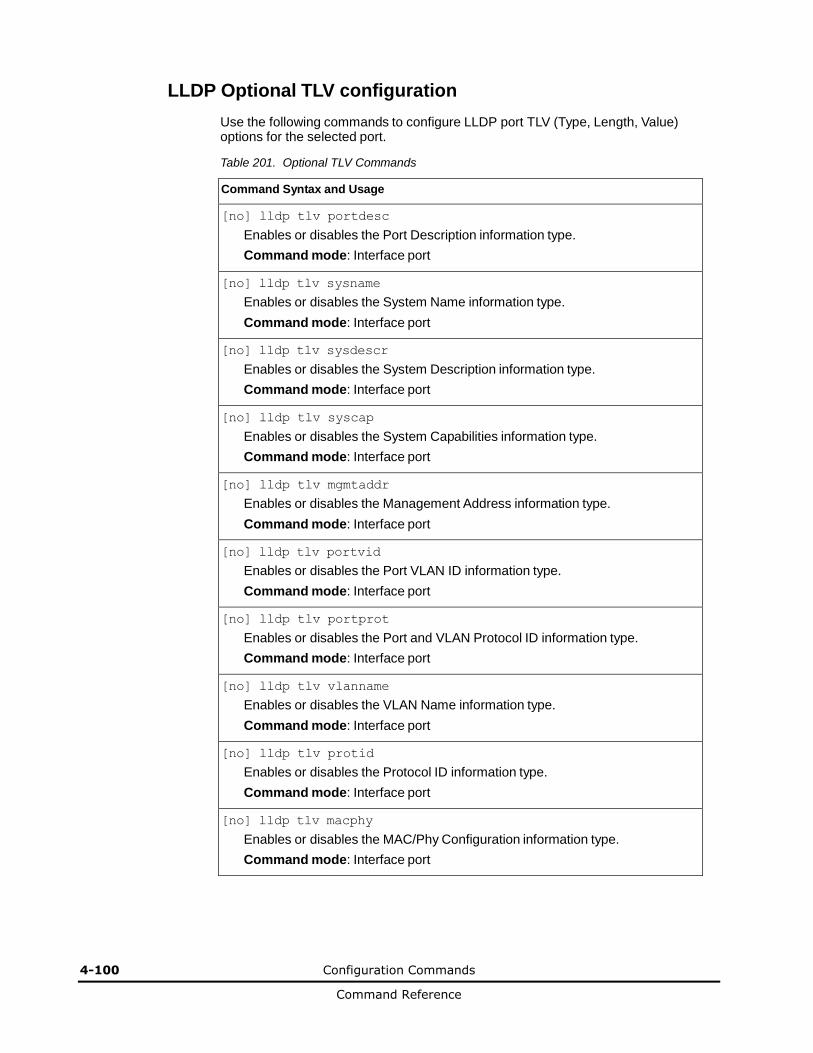
4-100 Configuration Commands
Command Reference
LLDP Optional TLV configuration
Use the following commands to configure LLDP port TLV (Type, Length, Value) options for the selected port.
Table 201. Optional TLV Commands
Command Syntax and Usage
[no] lldp tlv portdesc
Enables or disables the Port Description information type.
Command mode: Interface port
[no] lldp tlv sysname
Enables or disables the System Name information type.
Command mode: Interface port
[no] lldp tlv sysdescr
Enables or disables the System Description information type.
Command mode: Interface port
[no] lldp tlv syscap
Enables or disables the System Capabilities information type.
Command mode: Interface port
[no] lldp tlv mgmtaddr
Enables or disables the Management Address information type.
Command mode: Interface port
[no] lldp tlv portvid
Enables or disables the Port VLAN ID information type.
Command mode: Interface port
[no] lldp tlv portprot
Enables or disables the Port and VLAN Protocol ID information type.
Command mode: Interface port
[no] lldp tlv vlanname
Enables or disables the VLAN Name information type.
Command mode: Interface port
[no] lldp tlv protid
Enables or disables the Protocol ID information type.
Command mode: Interface port
[no] lldp tlv macphy
Enables or disables the MAC/Phy Configuration information type.
Command mode: Interface port
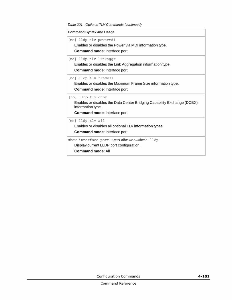
Configuration Commands 4-101
Command Reference
Table 201. Optional TLV Commands (continued)
Command Syntax and Usage
[no] lldp tlv powermdi
Enables or disables the Power via MDI information type.
Command mode: Interface port
[no] lldp tlv linkaggr
Enables or disables the Link Aggregation information type.
Command mode: Interface port
[no] lldp tlv framesz
Enables or disables the Maximum Frame Size information type.
Command mode: Interface port
[no] lldp tlv dcbx
Enables or disables the Data Center Bridging Capability Exchange (DCBX) information type.
Command mode: Interface port
[no] lldp tlv all
Enables or disables all optional TLV information types.
Command mode: Interface port
show interface port <port alias or number> lldp
Display current LLDP port configuration.
Command mode: All
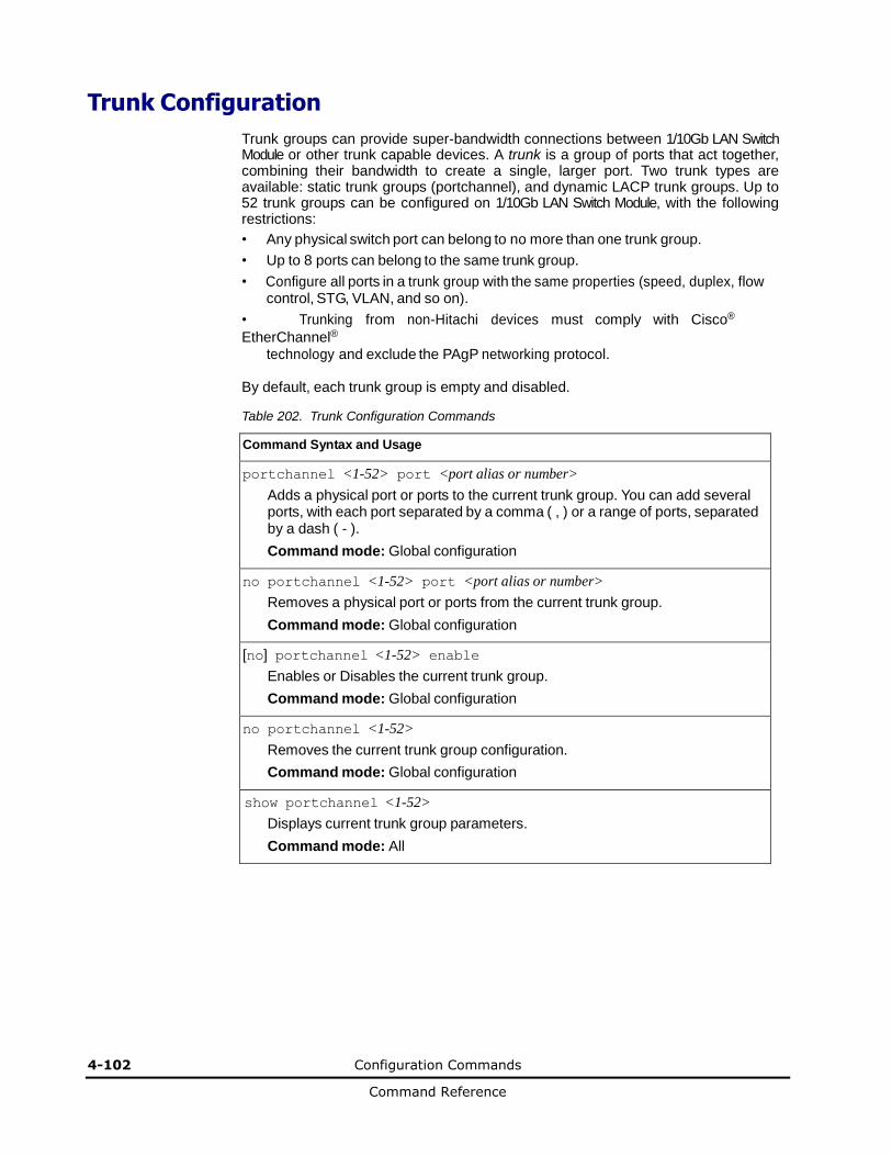
4-102 Configuration Commands
Command Reference
Trunk Configuration
Trunk groups can provide super-bandwidth connections between 1/10Gb LAN Switch Module or other trunk capable devices. A trunk is a group of ports that act together, combining their bandwidth to create a single, larger port. Two trunk types are available: static trunk groups (portchannel), and dynamic LACP trunk groups. Up to 52 trunk groups can be configured on 1/10Gb LAN Switch Module, with the following restrictions:
• Any physical switch port can belong to no more than one trunk group.
• Up to 8 ports can belong to the same trunk group.
• Configure all ports in a trunk group with the same properties (speed, duplex, flow control, STG, VLAN, and so on).
• Trunking from non-Hitachi devices must comply with Cisco®
EtherChannel®
technology and exclude the PAgP networking protocol.
By default, each trunk group is empty and disabled.
Table 202. Trunk Configuration Commands
Command Syntax and Usage
portchannel <1-52> port <port alias or number>
Adds a physical port or ports to the current trunk group. You can add several ports, with each port separated by a comma ( , ) or a range of ports, separated by a dash ( - ).
Command mode: Global configuration
no portchannel <1-52> port <port alias or number>
Removes a physical port or ports from the current trunk group.
Command mode: Global configuration
[no] portchannel <1-52> enable
Enables or Disables the current trunk group.
Command mode: Global configuration
no portchannel <1-52>
Removes the current trunk group configuration.
Command mode: Global configuration
show portchannel <1-52>
Displays current trunk group parameters.
Command mode: All
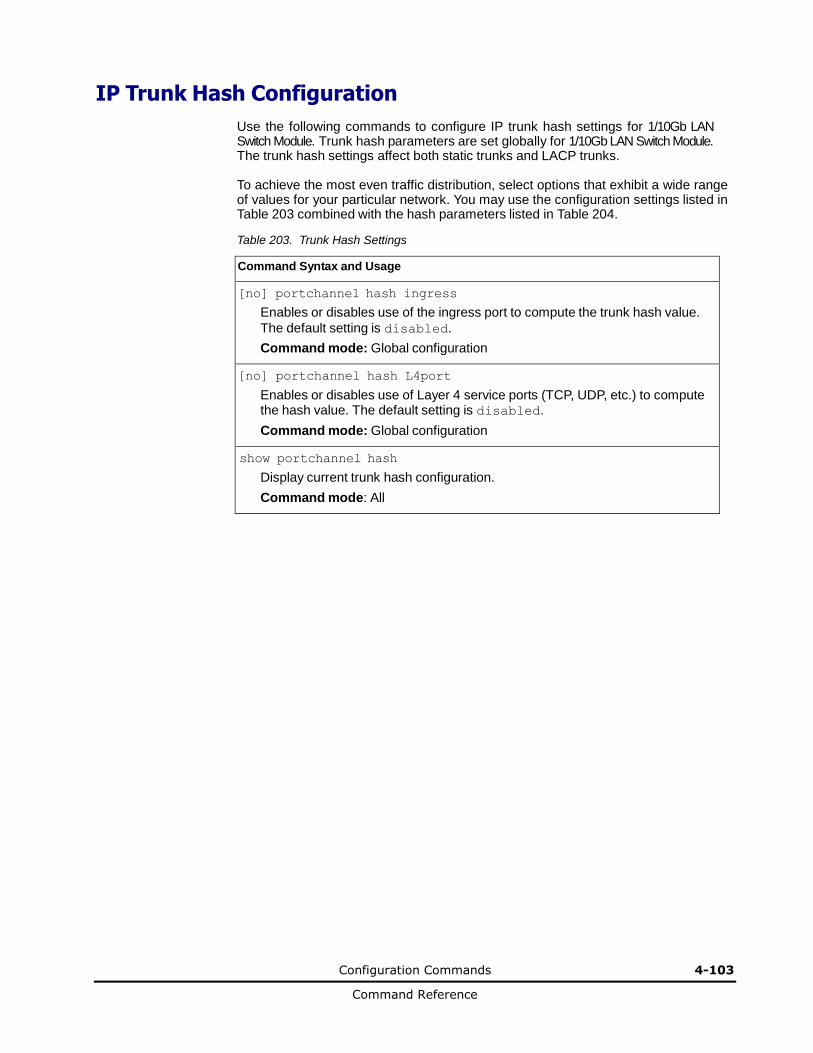
Configuration Commands 4-103
Command Reference
IP Trunk Hash Configuration
Use the following commands to configure IP trunk hash settings for 1/10Gb LAN Switch Module. Trunk hash parameters are set globally for 1/10Gb LAN Switch Module. The trunk hash settings affect both static trunks and LACP trunks.
To achieve the most even traffic distribution, select options that exhibit a wide range of values for your particular network. You may use the configuration settings listed in Table 203 combined with the hash parameters listed in Table 204.
Table 203. Trunk Hash Settings
Command Syntax and Usage
[no] portchannel hash ingress
Enables or disables use of the ingress port to compute the trunk hash value.
The default setting is disabled.
Command mode: Global configuration
[no] portchannel hash L4port
Enables or disables use of Layer 4 service ports (TCP, UDP, etc.) to compute the hash value. The default setting is disabled.
Command mode: Global configuration
show portchannel hash
Display current trunk hash configuration.
Command mode: All

4-104 Configuration Commands
Command Reference
IP Trunk Hash Parameters
You can enable one or two of the following parameters, to configure any of the following valid combinations:
• SMAC (source MAC only)
• DMAC (destination MAC only)
• SIP (source IP only)
• DIP (destination IP only)
• SIP + DIP (source IP and destination IP)
• SMAC + DMAC (source MAC and destination MAC)
Use the following commands to configure trunk hash parameters for 1/10Gb LAN Switch Module.
Table 204. Trunk Hash Parameters
Command Syntax and Usage
portchannel hash source-mac-address
Enable trunk hashing on the source MAC.
Command mode: Global configuration
portchannel hash destination-mac-address
Enable trunk hashing on the destination MAC.
Command mode: Global configuration
portchannel hash source-ip-address
Enable trunk hashing on the source IP.
Command mode: Global configuration
portchannel hash destination-ip-address
Enable trunk hashing on the destination IP.
Command mode: Global configuration
portchannel hash source-destination-ip
Enable trunk hashing on the source and destination IP.
Command mode: Global configuration
portchannel hash source-destination-mac
Enable trunk hashing on the source and destination MAC address.
Command mode: Global configuration
show portchannel hash
Display current trunk hash settings.
Command mode: All

Configuration Commands 4-105
Command Reference
Link Aggregation Control Protocol Configuration
Use the following commands to configure Link Aggregation Control Protocol (LACP) for 1/10Gb LAN Switch Module.
Table 205. Link Aggregation Control Protocol Commands
Command Syntax and Usage
lacp system-priority <1-65535>
Defines the priority value for 1/10Gb LAN Switch Module. Lower numbers provide higher priority. The default value is 32768.
Command mode: Global configuration
lacp timeout {short|long}
Defines the timeout period before invalidating LACP data from a remote partner. Choose short (3 seconds) or long (90 seconds). The default value
is long.
Note: It is recommended that you use a timeout value of long, to reduce
LACPDU processing. If your 1/10Gb LAN Switch Module’s CPU utilization rate remains at 100% for periods of 90 seconds or more, consider using static trunks instead of LACP.
Command mode: Global configuration
default lacp [system-priority|timeout]
Restores either the VFSM priority value, timeout period or both to their default values.
Command mode: Global configuration
no lacp <1-65535>
Deletes a selected LACP trunk, based on its admin key. This command is equivalent to disabling LACP on each of the ports configured with the same admin key.
Command mode: Global configuration
show lacp
Display current LACP configuration.
Command mode: All

4-106 Configuration Commands
Command Reference
LACP Port Configuration
Use the following commands to configure Link Aggregation Control Protocol (LACP) for the selected port.
Table 206. Link Aggregation Control Protocol Commands
Command Syntax and Usage
lacp mode {off|active|passive}
Set the LACP mode for this port, as follows:
– off
Turn LACP off for this port. You can use this port to manually configure a
static trunk. The default value is off.
– active
Turn LACP on and set this port to active. Active ports initiate LACPDUs.
– passive
Turn LACP on and set this port to passive. Passive ports do not initiate
LACPDUs, but respond to LACPDUs from active ports.
Command mode: Interface port
lacp priority <1-65535>
Sets the priority value for the selected port. Lower numbers provide higher priority. The default value is 32768.
Command mode: Interface port
lacp key <1-65535>
Set the admin key for this port. Only ports with the same admin key and oper key (operational state generated internally) can form a LACP trunk group.
Command mode: Interface port
port-channel min-links <1-8>
Set the minimum number of links for this port. If the specified minimum number
of ports are not available, the trunk is placed in the down state.
Command mode: Interface port
default lacp [key | mode | priority]
Restores the selected parameters to their default values.
Command mode: Interface port
show interface port <port alias or number> lacp
Displays the current LACP configuration for this port.
Command mode: All
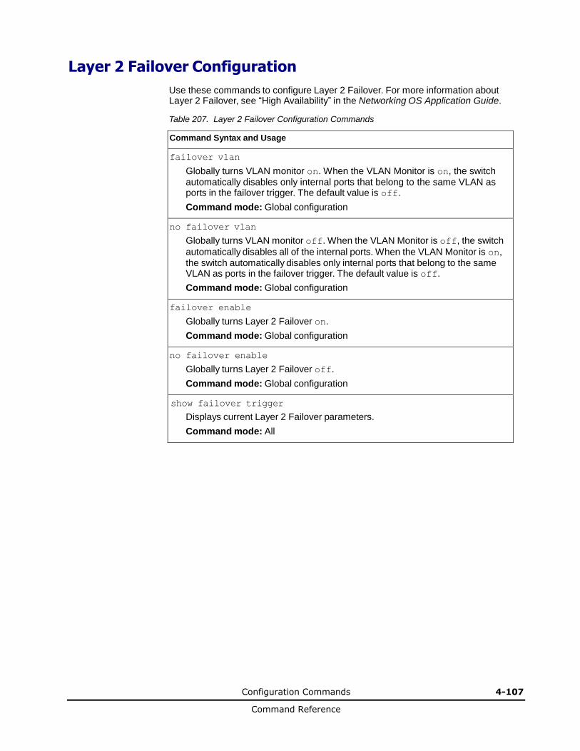
Configuration Commands 4-107
Command Reference
Layer 2 Failover Configuration
Use these commands to configure Layer 2 Failover. For more information about Layer 2 Failover, see “High Availability” in the Networking OS Application Guide.
Table 207. Layer 2 Failover Configuration Commands
Command Syntax and Usage
failover vlan
Globally turns VLAN monitor on. When the VLAN Monitor is on, the switch automatically disables only internal ports that belong to the same VLAN as ports in the failover trigger. The default value is off.
Command mode: Global configuration
no failover vlan
Globally turns VLAN monitor off. When the VLAN Monitor is off, the switch
automatically disables all of the internal ports. When the VLAN Monitor is on, the switch automatically disables only internal ports that belong to the same VLAN as ports in the failover trigger. The default value is off.
Command mode: Global configuration
failover enable
Globally turns Layer 2 Failover on.
Command mode: Global configuration
no failover enable
Globally turns Layer 2 Failover off.
Command mode: Global configuration
show failover trigger
Displays current Layer 2 Failover parameters.
Command mode: All
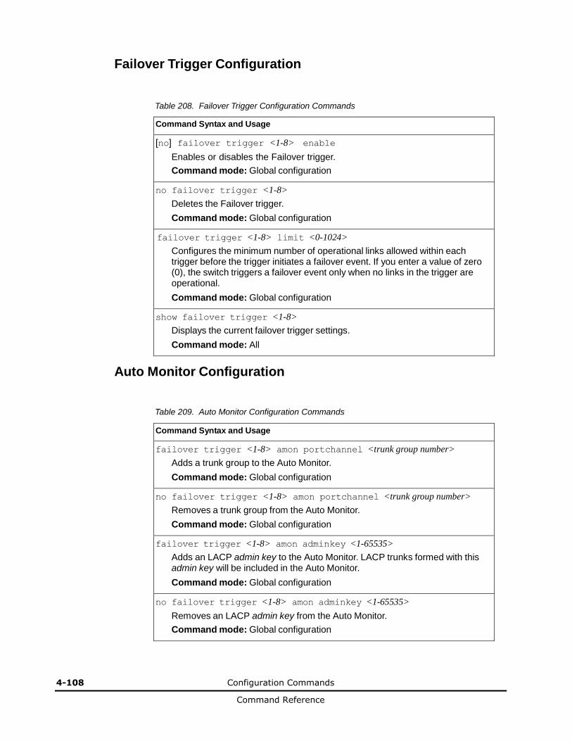
4-108 Configuration Commands
Command Reference
Failover Trigger Configuration
Table 208. Failover Trigger Configuration Commands
Command Syntax and Usage
[no] failover trigger <1-8> enable
Enables or disables the Failover trigger.
Command mode: Global configuration
no failover trigger <1-8>
Deletes the Failover trigger.
Command mode: Global configuration
failover trigger <1-8> limit <0-1024>
Configures the minimum number of operational links allowed within each trigger before the trigger initiates a failover event. If you enter a value of zero (0), the switch triggers a failover event only when no links in the trigger are operational.
Command mode: Global configuration
show failover trigger <1-8>
Displays the current failover trigger settings.
Command mode: All
Auto Monitor Configuration
Table 209. Auto Monitor Configuration Commands
Command Syntax and Usage
failover trigger <1-8> amon portchannel <trunk group number>
Adds a trunk group to the Auto Monitor.
Command mode: Global configuration
no failover trigger <1-8> amon portchannel <trunk group number>
Removes a trunk group from the Auto Monitor.
Command mode: Global configuration
failover trigger <1-8> amon adminkey <1-65535>
Adds an LACP admin key to the Auto Monitor. LACP trunks formed with this admin key will be included in the Auto Monitor.
Command mode: Global configuration
no failover trigger <1-8> amon adminkey <1-65535>
Removes an LACP admin key from the Auto Monitor.
Command mode: Global configuration
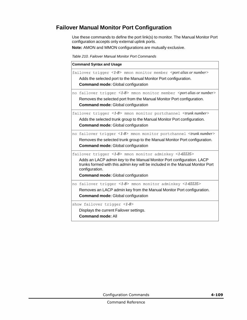
Configuration Commands 4-109
Command Reference
Failover Manual Monitor Port Configuration
Use these commands to define the port link(s) to monitor. The Manual Monitor Port configuration accepts only external uplink ports.
Note: AMON and MMON configurations are mutually exclusive.
Table 210. Failover Manual Monitor Port Commands
Command Syntax and Usage
failover trigger <1-8> mmon monitor member <port alias or number>
Adds the selected port to the Manual Monitor Port configuration.
Command mode: Global configuration
no failover trigger <1-8> mmon monitor member <port alias or number>
Removes the selected port from the Manual Monitor Port configuration.
Command mode: Global configuration
failover trigger <1-8> mmon monitor portchannel <trunk number>
Adds the selected trunk group to the Manual Monitor Port configuration.
Command mode: Global configuration
no failover trigger <1-8> mmon monitor portchannel <trunk number>
Removes the selected trunk group to the Manual Monitor Port configuration.
Command mode: Global configuration
failover trigger <1-8> mmon monitor adminkey <1-65535>
Adds an LACP admin key to the Manual Monitor Port configuration. LACP trunks formed with this admin key will be included in the Manual Monitor Port configuration.
Command mode: Global configuration
no failover trigger <1-8> mmon monitor adminkey <1-65535>
Removes an LACP admin key from the Manual Monitor Port configuration.
Command mode: Global configuration
show failover trigger <1-8>
Displays the current Failover settings.
Command mode: All
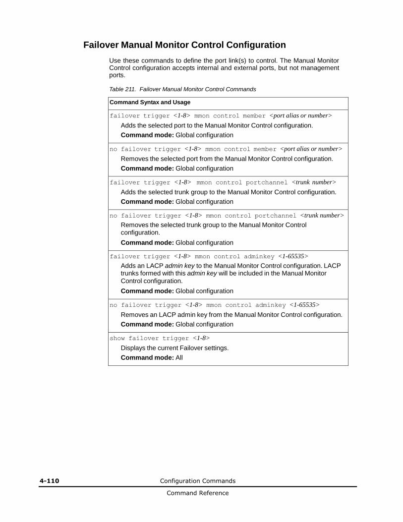
4-110 Configuration Commands
Command Reference
Failover Manual Monitor Control Configuration
Use these commands to define the port link(s) to control. The Manual Monitor Control configuration accepts internal and external ports, but not management ports.
Table 211. Failover Manual Monitor Control Commands
Command Syntax and Usage
failover trigger <1-8> mmon control member <port alias or number>
Adds the selected port to the Manual Monitor Control configuration.
Command mode: Global configuration
no failover trigger <1-8> mmon control member <port alias or number>
Removes the selected port from the Manual Monitor Control configuration.
Command mode: Global configuration
failover trigger <1-8> mmon control portchannel <trunk number>
Adds the selected trunk group to the Manual Monitor Control configuration.
Command mode: Global configuration
no failover trigger <1-8> mmon control portchannel <trunk number>
Removes the selected trunk group to the Manual Monitor Control configuration.
Command mode: Global configuration
failover trigger <1-8> mmon control adminkey <1-65535>
Adds an LACP admin key to the Manual Monitor Control configuration. LACP trunks formed with this admin key will be included in the Manual Monitor Control configuration.
Command mode: Global configuration
no failover trigger <1-8> mmon control adminkey <1-65535>
Removes an LACP admin key from the Manual Monitor Control configuration.
Command mode: Global configuration
show failover trigger <1-8>
Displays the current Failover settings.
Command mode: All
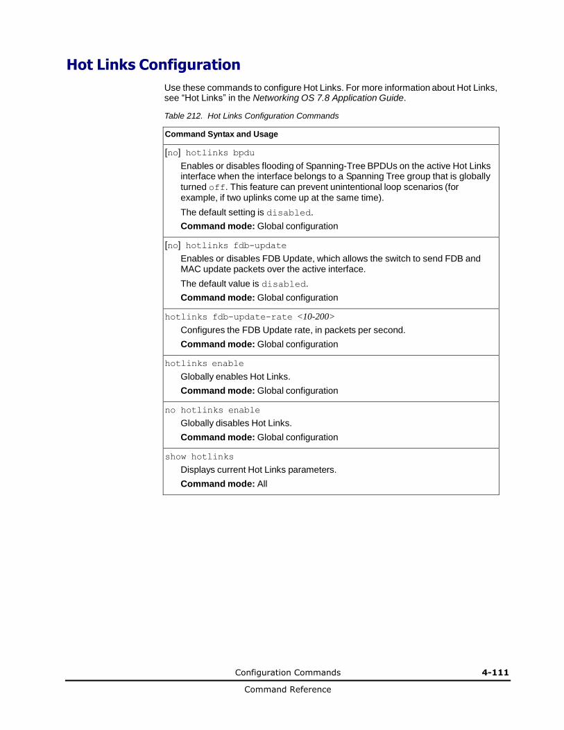
Configuration Commands 4-111
Command Reference
Hot Links Configuration
Use these commands to configure Hot Links. For more information about Hot Links, see “Hot Links” in the Networking OS 7.8 Application Guide.
Table 212. Hot Links Configuration Commands
Command Syntax and Usage
[no] hotlinks bpdu
Enables or disables flooding of Spanning-Tree BPDUs on the active Hot Links interface when the interface belongs to a Spanning Tree group that is globally turned off. This feature can prevent unintentional loop scenarios (for example, if two uplinks come up at the same time).
The default setting is disabled.
Command mode: Global configuration
[no] hotlinks fdb-update
Enables or disables FDB Update, which allows the switch to send FDB and MAC update packets over the active interface.
The default value is disabled.
Command mode: Global configuration
hotlinks fdb-update-rate <10-200>
Configures the FDB Update rate, in packets per second.
Command mode: Global configuration
hotlinks enable
Globally enables Hot Links.
Command mode: Global configuration
no hotlinks enable
Globally disables Hot Links.
Command mode: Global configuration
show hotlinks
Displays current Hot Links parameters.
Command mode: All
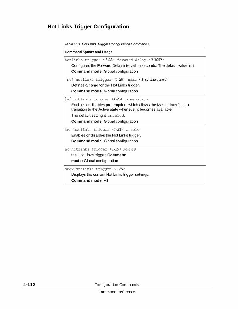
4-112 Configuration Commands
Command Reference
Hot Links Trigger Configuration
Table 213. Hot Links Trigger Configuration Commands
Command Syntax and Usage
hotlinks trigger <1-25> forward-delay <0-3600>
Configures the Forward Delay interval, in seconds. The default value is 1.
Command mode: Global configuration
[no] hotlinks trigger <1-25> name <1-32 characters>
Defines a name for the Hot Links trigger.
Command mode: Global configuration
[no] hotlinks trigger <1-25> preemption
Enables or disables pre-emption, which allows the Master interface to transition to the Active state whenever it becomes available.
The default setting is enabled.
Command mode: Global configuration
[no] hotlinks trigger <1-25> enable
Enables or disables the Hot Links trigger.
Command mode: Global configuration
no hotlinks trigger <1-25> Deletes
the Hot Links trigger. Command
mode: Global configuration
show hotlinks trigger <1-25>
Displays the current Hot Links trigger settings.
Command mode: All
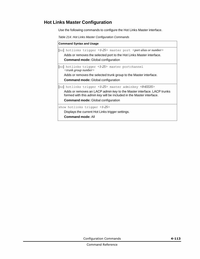
Configuration Commands 4-113
Command Reference
Hot Links Master Configuration
Use the following commands to configure the Hot Links Master interface.
Table 214. Hot Links Master Configuration Commands
Command Syntax and Usage
[no] hotlinks trigger <1-25> master port <port alias or number>
Adds or removes the selected port to the Hot Links Master interface.
Command mode: Global configuration
[no] hotlinks trigger <1-25> master portchannel <trunk group number>
Adds or removes the selected trunk group to the Master interface.
Command mode: Global configuration
[no] hotlinks trigger <1-25> master adminkey <0-65535>
Adds or removes an LACP admin key to the Master interface. LACP trunks formed with this admin key will be included in the Master interface.
Command mode: Global configuration
show hotlinks trigger <1-25>
Displays the current Hot Links trigger settings.
Command mode: All
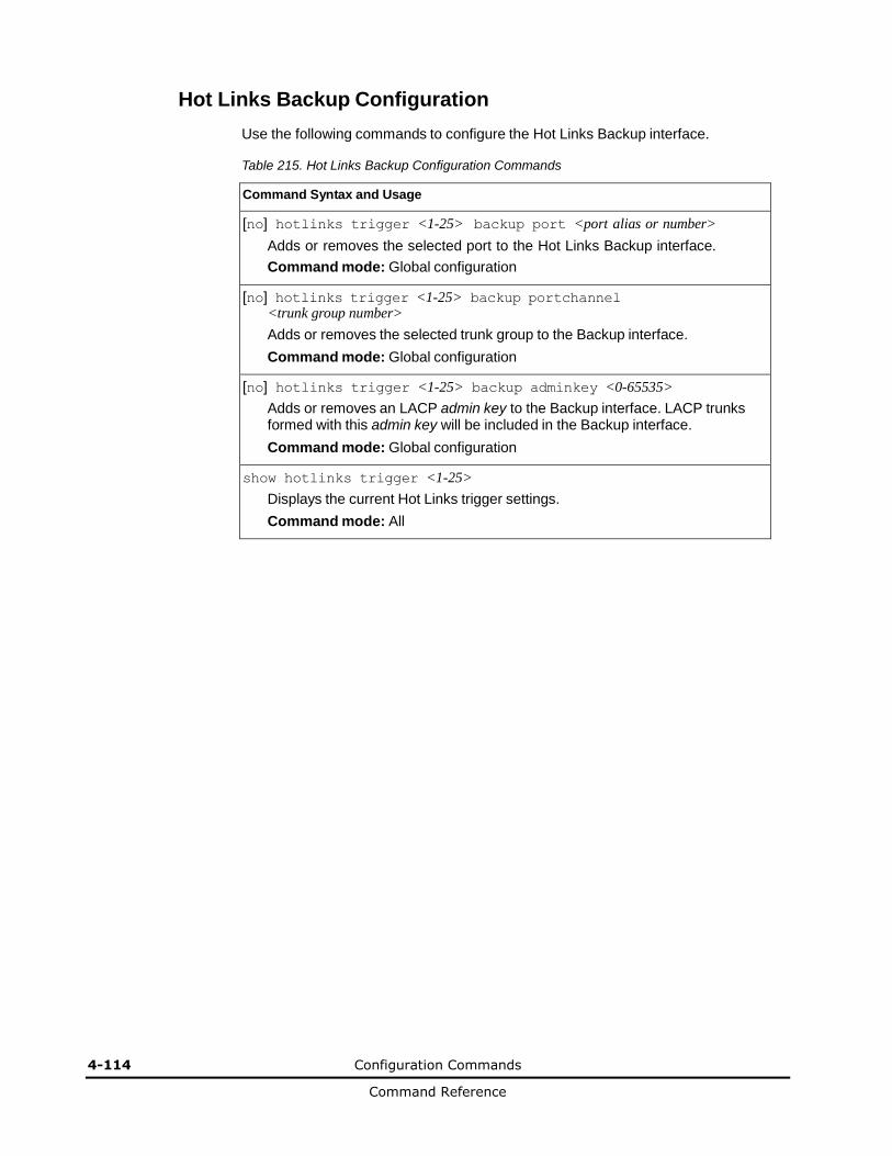
4-114 Configuration Commands
Command Reference
Hot Links Backup Configuration
Use the following commands to configure the Hot Links Backup interface.
Table 215. Hot Links Backup Configuration Commands
Command Syntax and Usage
[no] hotlinks trigger <1-25> backup port <port alias or number>
Adds or removes the selected port to the Hot Links Backup interface.
Command mode: Global configuration
[no] hotlinks trigger <1-25> backup portchannel <trunk group number>
Adds or removes the selected trunk group to the Backup interface.
Command mode: Global configuration
[no] hotlinks trigger <1-25> backup adminkey <0-65535>
Adds or removes an LACP admin key to the Backup interface. LACP trunks formed with this admin key will be included in the Backup interface.
Command mode: Global configuration
show hotlinks trigger <1-25>
Displays the current Hot Links trigger settings.
Command mode: All
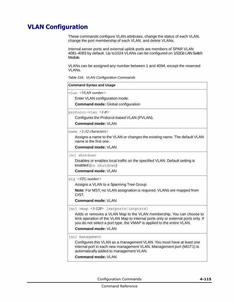
Configuration Commands 4-115
Command Reference
VLAN Configuration
These commands configure VLAN attributes, change the status of each VLAN, change the port membership of each VLAN, and delete VLANs.
Internal server ports and external uplink ports are members of SPAR VLAN 4081-4083 by default. Up to1024 VLANs can be configured on 1/10Gb LAN Switch Module.
VLANs can be assigned any number between 1 and 4094, except the reserved VLANs.
Table 216. VLAN Configuration Commands
Command Syntax and Usage
vlan <VLAN number>
Enter VLAN configuration mode.
Command mode: Global configuration
protocol-vlan <1-8>
Configures the Protocol-based VLAN (PVLAN).
Command mode: VLAN
name <1-32 characters>
Assigns a name to the VLAN or changes the existing name. The default VLAN name is the first one.
Command mode: VLAN
[no] shutdown
Disables or enables local traffic on the specified VLAN. Default setting is
enabled (no shutdown)
Command mode: VLAN
stg <STG number>
Assigns a VLAN to a Spanning Tree Group.
Note: For MST, no VLAN assignation is required. VLANs are mapped from CIST.
Command mode: VLAN
[no] vmap <1-128> [extports|intports]
Adds or removes a VLAN Map to the VLAN membership. You can choose to limit operation of the VLAN Map to internal ports only or external ports only. If you do not select a port type, the VMAP is applied to the entire VLAN.
Command mode: VLAN
[no] management
Configures this VLAN as a management VLAN. You must have at least one internal port in each new management VLAN. Management port (MGT1) is automatically added to management VLAN.
Command mode: VLAN

4-116 Configuration Commands
Command Reference
Table 216. VLAN Configuration Commands (continued)
Command Syntax and Usage
[no] flood
Configures the switch to flood unregistered IP multicast traffic to all ports. The
default setting is enabled.
Note: If none of the IGMP hosts reside on the VLAN of the streaming server for a IPMC group, you must disable IGMP flooding to ensure that multicast data is forwarded across the VLANs for that IPMC group.
Command mode: VLAN
[no] cpu
Configures the switch to forward unregistered IP multicast traffic to the MP, which adds an entry in the IPMC table, as follows:
– If no Mrouter is present, drop subsequent packets with same IPMC.
– If an Mrouter is present, forward subsequent packets to the Mrouter(s) on
the ingress VLAN.
The default setting is enabled.
Note: If both flood and cpu are disabled, then the switch drops all unregistered IPMC traffic.
Command mode: VLAN
[no] optflood
Enables or disables optimized flooding. When enabled, optimized flooding avoids packet loss during the learning period. The default setting is
disabled.
Command mode: VLAN
show vlan information
Displays the current VLAN configuration.
Command mode: All
Note: All ports must belong to at least one VLAN. Any port which is removed from a VLAN and which is not a member of any other VLAN is automatically added to default VLAN 1. You cannot add a port to more than one VLAN unless the port has
VLAN tagging turned on.

Configuration Commands 4-117
Command Reference
Protocol-Based VLAN Configuration
Use the following commands to configure Protocol-based VLAN for the selected VLAN.
Table 217. Protocol VLAN Configuration Commands
Command Syntax and Usage
protocol-vlan <1-8> frame-type {ether2|llc|snap} <Ethernet type>
Configures the frame type and the Ethernet type for the selected protocol.
Ethernet type consists of a 4-digit (16 bit) hex code, such as 0080 (IPv4).
Command mode: VLAN
protocol-vlan <1-8> protocol <protocol type>
Selects a pre-defined protocol, as follows:
– decEther2:DEC Local Area Transport
– ipv4Ether2:Internet IP (IPv4)
– ipv6Ether2:IPv6
– ipx802.2:Novell IPX 802.2
– ipx802.3:Novell IPX 802.3
– ipxEther2:Novell IPX
– ipxSnap:Novell IPX SNAP
– netbios:NetBIOS 802.2
– rarpEther2:Reverse ARP
– sna802.2:SNA 802.2
– snaEther2:Hitachi SNA Service on Ethernet
– vinesEther2:Banyan VINES
– xnsEther2:XNS Compatibility
Command mode: VLAN
protocol-vlan <1-8> priority <0-7>
Configures the priority value for this PVLAN.
Command mode: VLAN
protocol-vlan <1-8> member <port alias or number>
Adds a port to the selected PVLAN.
Command mode: VLAN
no protocol-vlan <1-8> member <port alias or number>
Removes a port from the selected PVLAN.
Command mode: VLAN
[no] protocol-vlan <1-8> tag-pvlan <port alias or number>
Defines a port that will be tagged by the selected protocol on this VLAN.
Command mode: VLAN
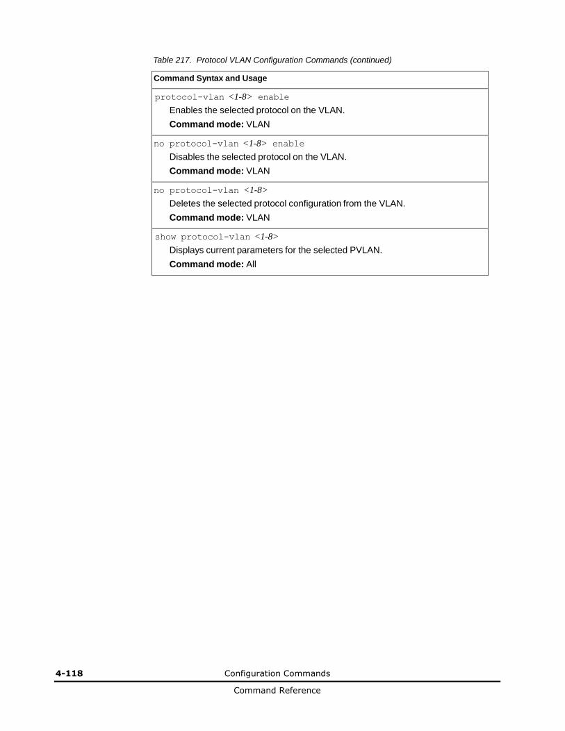
4-118 Configuration Commands
Command Reference
Table 217. Protocol VLAN Configuration Commands (continued)
Command Syntax and Usage
protocol-vlan <1-8> enable
Enables the selected protocol on the VLAN.
Command mode: VLAN
no protocol-vlan <1-8> enable
Disables the selected protocol on the VLAN.
Command mode: VLAN
no protocol-vlan <1-8>
Deletes the selected protocol configuration from the VLAN.
Command mode: VLAN
show protocol-vlan <1-8>
Displays current parameters for the selected PVLAN.
Command mode: All
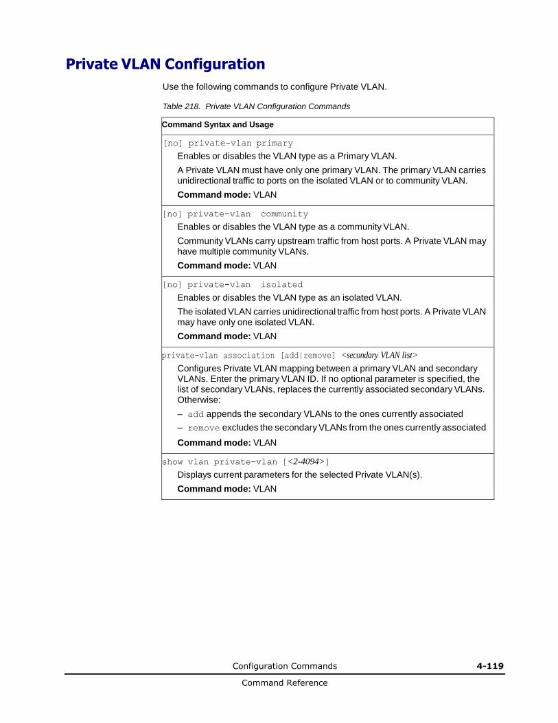
Configuration Commands 4-119
Command Reference
Private VLAN Configuration
Use the following commands to configure Private VLAN.
Table 218. Private VLAN Configuration Commands
Command Syntax and Usage
[no] private-vlan primary
Enables or disables the VLAN type as a Primary VLAN.
A Private VLAN must have only one primary VLAN. The primary VLAN carries unidirectional traffic to ports on the isolated VLAN or to community VLAN.
Command mode: VLAN
[no] private-vlan community
Enables or disables the VLAN type as a community VLAN.
Community VLANs carry upstream traffic from host ports. A Private VLAN may have multiple community VLANs.
Command mode: VLAN
[no] private-vlan isolated
Enables or disables the VLAN type as an isolated VLAN.
The isolated VLAN carries unidirectional traffic from host ports. A Private VLAN may have only one isolated VLAN.
Command mode: VLAN
private-vlan association [add|remove] <secondary VLAN list>
Configures Private VLAN mapping between a primary VLAN and secondary VLANs. Enter the primary VLAN ID. If no optional parameter is specified, the list of secondary VLANs, replaces the currently associated secondary VLANs. Otherwise:
– add appends the secondary VLANs to the ones currently associated
– remove excludes the secondary VLANs from the ones currently associated
Command mode: VLAN
show vlan private-vlan [<2-4094>]
Displays current parameters for the selected Private VLAN(s).
Command mode: VLAN
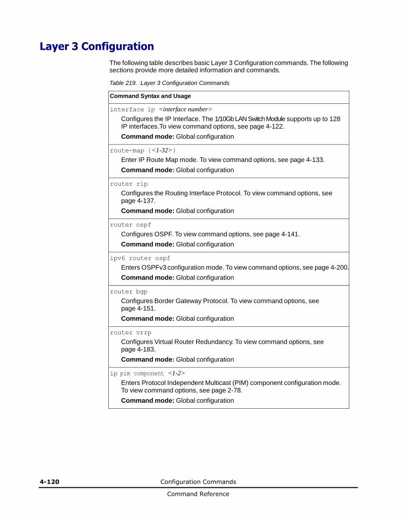
4-120 Configuration Commands
Command Reference
Layer 3 Configuration
The following table describes basic Layer 3 Configuration commands. The following sections provide more detailed information and commands.
Table 219. Layer 3 Configuration Commands
Command Syntax and Usage
interface ip <interface number>
Configures the IP Interface. The 1/10Gb LAN Switch Module supports up to 128 IP interfaces.To view command options, see page 4-122.
Command mode: Global configuration
route-map {<1-32>}
Enter IP Route Map mode. To view command options, see page 4-133.
Command mode: Global configuration
router rip
Configures the Routing Interface Protocol. To view command options, see page 4-137.
Command mode: Global configuration
router ospf
Configures OSPF. To view command options, see page 4-141.
Command mode: Global configuration
ipv6 router ospf
Enters OSPFv3 configuration mode. To view command options, see page 4-200.
Command mode: Global configuration
router bgp
Configures Border Gateway Protocol. To view command options, see page 4-151.
Command mode: Global configuration
router vrrp
Configures Virtual Router Redundancy. To view command options, see page 4-183.
Command mode: Global configuration
ip pim component <1-2>
Enters Protocol Independent Multicast (PIM) component configuration mode. To view command options, see page 2-78.
Command mode: Global configuration

Configuration Commands 4-121
Command Reference
Table 219. Layer 3 Configuration Commands
Command Syntax and Usage
ip router-id <IP address>
Sets the router ID.
Command mode: Global configuration
show layer3
Displays the current IP configuration.
Command mode: All
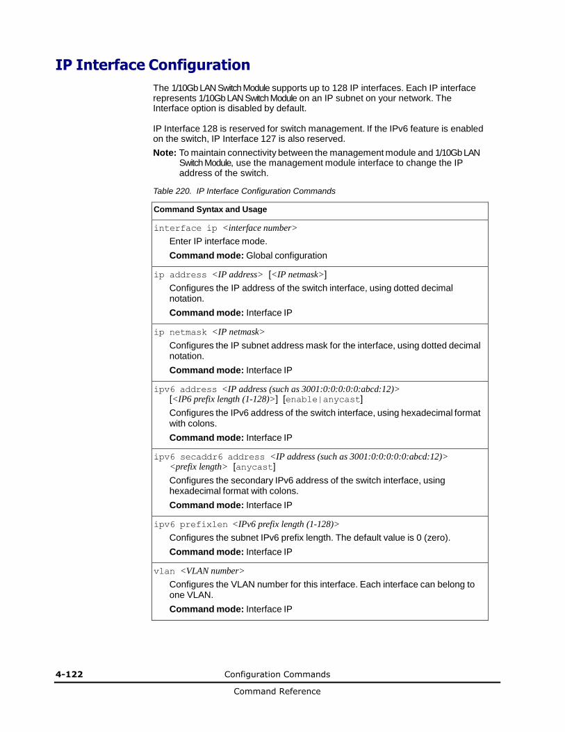
4-122 Configuration Commands
Command Reference
IP Interface Configuration
The 1/10Gb LAN Switch Module supports up to 128 IP interfaces. Each IP interface represents 1/10Gb LAN Switch Module on an IP subnet on your network. The Interface option is disabled by default.
IP Interface 128 is reserved for switch management. If the IPv6 feature is enabled on the switch, IP Interface 127 is also reserved.
Note: To maintain connectivity between the management module and 1/10Gb LAN Switch Module, use the management module interface to change the IP address of the switch.
Table 220. IP Interface Configuration Commands
Command Syntax and Usage
interface ip <interface number>
Enter IP interface mode.
Command mode: Global configuration
ip address <IP address> [<IP netmask>]
Configures the IP address of the switch interface, using dotted decimal notation.
Command mode: Interface IP
ip netmask <IP netmask>
Configures the IP subnet address mask for the interface, using dotted decimal notation.
Command mode: Interface IP
ipv6 address <IP address (such as 3001:0:0:0:0:0:abcd:12)> [<IP6 prefix length (1-128)>] [enable|anycast]
Configures the IPv6 address of the switch interface, using hexadecimal format with colons.
Command mode: Interface IP
ipv6 secaddr6 address <IP address (such as 3001:0:0:0:0:0:abcd:12)> <prefix length> [anycast]
Configures the secondary IPv6 address of the switch interface, using hexadecimal format with colons.
Command mode: Interface IP
ipv6 prefixlen <IPv6 prefix length (1-128)>
Configures the subnet IPv6 prefix length. The default value is 0 (zero).
Command mode: Interface IP
vlan <VLAN number>
Configures the VLAN number for this interface. Each interface can belong to one VLAN.
Command mode: Interface IP
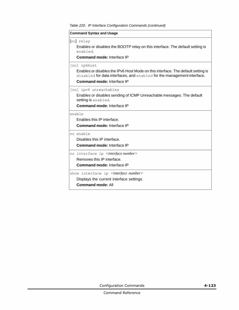
Configuration Commands 4-123
Command Reference
Table 220. IP Interface Configuration Commands (continued)
Command Syntax and Usage
[no] relay
Enables or disables the BOOTP relay on this interface. The default setting is
enabled.
Command mode: Interface IP
[no] ip6host
Enables or disables the IPv6 Host Mode on this interface. The default setting is disabled for data interfaces, and enabled for the management interface.
Command mode: Interface IP
[no] ipv6 unreachables
Enables or disables sending of ICMP Unreachable messages. The default
setting is enabled.
Command mode: Interface IP
enable
Enables this IP interface.
Command mode: Interface IP
no enable
Disables this IP interface.
Command mode: Interface IP
no interface ip <interface number>
Removes this IP interface.
Command mode: Interface IP
show interface ip <interface number>
Displays the current interface settings.
Command mode: All

4-124 Configuration Commands
Command Reference
IPv6 Neighbor Discovery Configuration
The following table describes the IPv6 Neighbor Discovery Configuration commands.
Table 221. IPv6 Neighbor Discovery Configuration Options
Command Syntax and Usage
[no] ipv6 nd suppress-ra
Enables or disables IPv6 Router Advertisements on the interface. The default
setting is disabled (suppress Router Advertisements).
Command mode: Interface IP
[no] ipv6 nd managed-config
Enables or disables the managed address configuration flag of the interface. When enabled, the host IP address can be set automatically through DHCP.
The default setting is disabled.
Command mode: Interface IP
[no] ipv6 nd other-config
Enables or disables the other stateful configuration flag, which allows the interface to use DHCP for other stateful configuration. The default setting is disabled.
Command mode: Interface IP
ipv6 nd ra-lifetime <0-9000>
Configures the IPv6 Router Advertisement lifetime interval. The RA lifetime
interval must be greater than or equal to the RA maximum interval (advint).
The default value is 1800 seconds.
Command mode: Interface IP
[no] ipv6 nd dad-attempts <1-10>
Configures the maximum number of duplicate address detection attempts.
The default value is 1.
Command mode: Interface IP
[no] ipv6 nd reachable-time <1-3600> [no] ipv6 nd reachable-time <1-3600000> ms
Configures the advertised reachability time, in seconds or milliseconds (ms). The default value is 30 seconds.
Command mode: Interface IP
[no] ipv6 nd ra-interval <4-1800>
Configures the Router Advertisement maximum interval. The default value is 600 seconds.
Note: Set the maximum RA interval to a value greater than or equal to 4/3 of the minimum RA interval.
Command mode: Interface IP
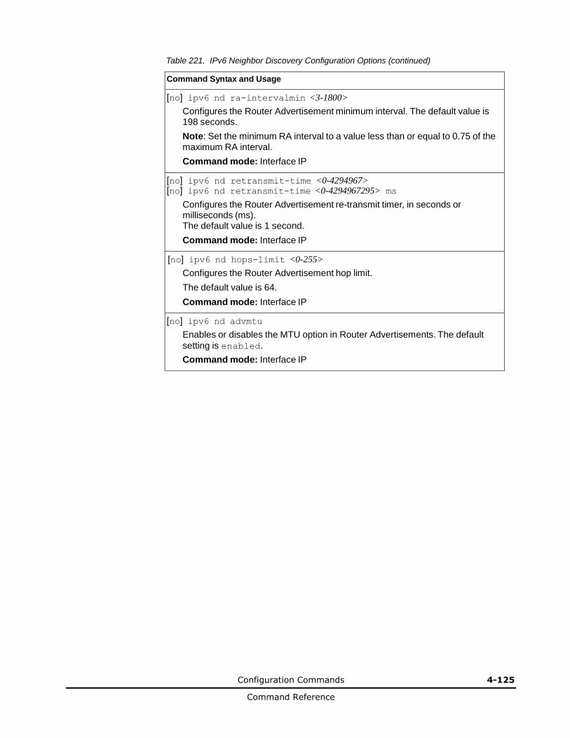
Configuration Commands 4-125
Command Reference
Table 221. IPv6 Neighbor Discovery Configuration Options (continued)
Command Syntax and Usage
[no] ipv6 nd ra-intervalmin <3-1800>
Configures the Router Advertisement minimum interval. The default value is 198 seconds.
Note: Set the minimum RA interval to a value less than or equal to 0.75 of the maximum RA interval.
Command mode: Interface IP
[no] ipv6 nd retransmit-time <0-4294967> [no] ipv6 nd retransmit-time <0-4294967295> ms
Configures the Router Advertisement re-transmit timer, in seconds or milliseconds (ms). The default value is 1 second.
Command mode: Interface IP
[no] ipv6 nd hops-limit <0-255>
Configures the Router Advertisement hop limit.
The default value is 64.
Command mode: Interface IP
[no] ipv6 nd advmtu
Enables or disables the MTU option in Router Advertisements. The default
setting is enabled.
Command mode: Interface IP
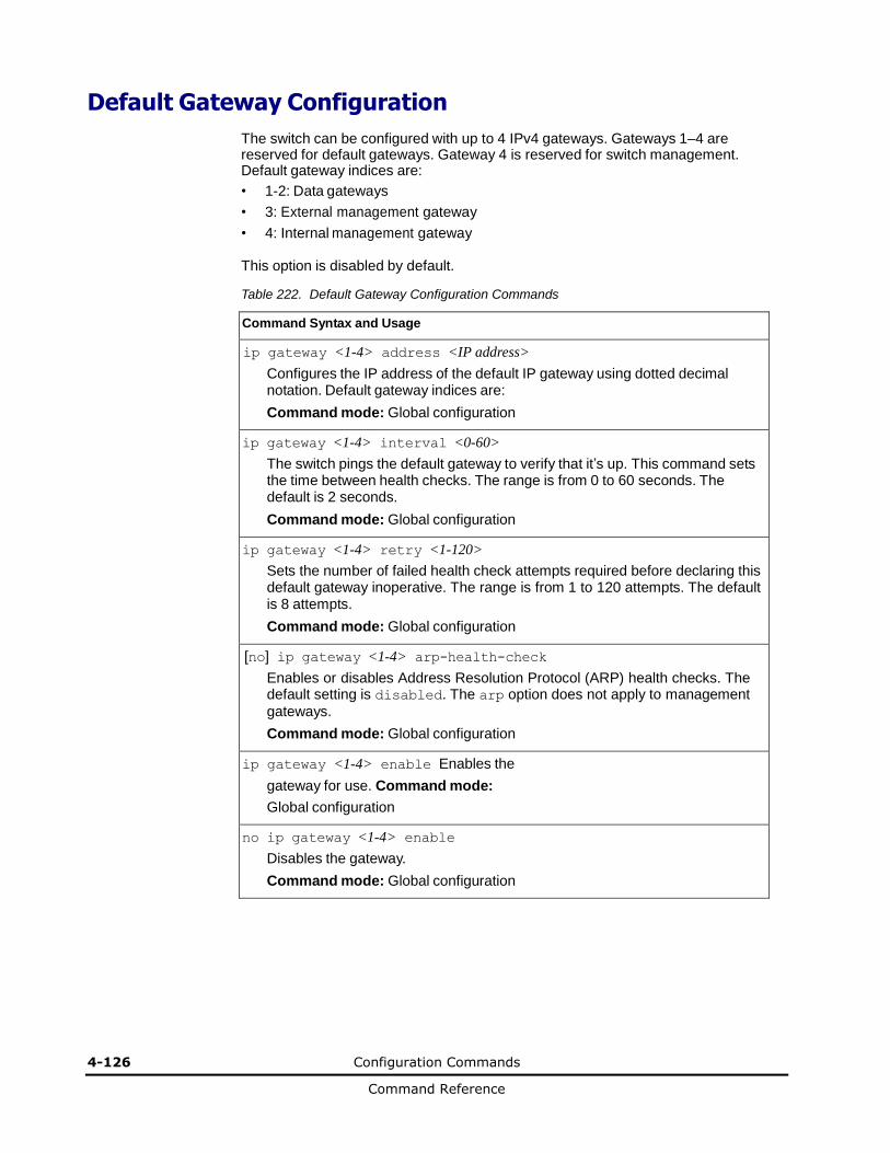
4-126 Configuration Commands
Command Reference
Default Gateway Configuration
The switch can be configured with up to 4 IPv4 gateways. Gateways 1–4 are reserved for default gateways. Gateway 4 is reserved for switch management. Default gateway indices are:
• 1-2: Data gateways
• 3: External management gateway
• 4: Internal management gateway
This option is disabled by default.
Table 222. Default Gateway Configuration Commands
Command Syntax and Usage
ip gateway <1-4> address <IP address>
Configures the IP address of the default IP gateway using dotted decimal notation. Default gateway indices are:
Command mode: Global configuration
ip gateway <1-4> interval <0-60>
The switch pings the default gateway to verify that it’s up. This command sets the time between health checks. The range is from 0 to 60 seconds. The default is 2 seconds.
Command mode: Global configuration
ip gateway <1-4> retry <1-120>
Sets the number of failed health check attempts required before declaring this default gateway inoperative. The range is from 1 to 120 attempts. The default is 8 attempts.
Command mode: Global configuration
[no] ip gateway <1-4> arp-health-check
Enables or disables Address Resolution Protocol (ARP) health checks. The default setting is disabled. The arp option does not apply to management
gateways.
Command mode: Global configuration
ip gateway <1-4> enable Enables the
gateway for use. Command mode:
Global configuration
no ip gateway <1-4> enable
Disables the gateway.
Command mode: Global configuration
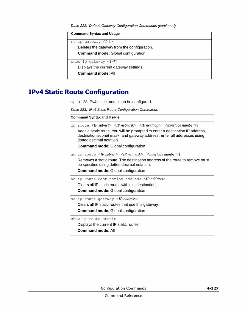
Configuration Commands 4-127
Command Reference
Table 222. Default Gateway Configuration Commands (continued)
Command Syntax and Usage
no ip gateway <1-4>
Deletes the gateway from the configuration.
Command mode: Global configuration
show ip gateway <1-4>
Displays the current gateway settings.
Command mode: All
IPv4 Static Route Configuration
Up to 128 IPv4 static routes can be configured.
Table 223. IPv4 Static Route Configuration Commands
Command Syntax and Usage
ip route <IP subnet> <IP netmask> <IP nexthop> [<interface number>]
Adds a static route. You will be prompted to enter a destination IP address, destination subnet mask, and gateway address. Enter all addresses using dotted decimal notation.
Command mode: Global configuration
no ip route <IP subnet> <IP netmask> [<interface number>]
Removes a static route. The destination address of the route to remove must be specified using dotted decimal notation.
Command mode: Global configuration
no ip route destination-address <IP address>
Clears all IP static routes with this destination.
Command mode: Global configuration
no ip route gateway <IP address>
Clears all IP static routes that use this gateway.
Command mode: Global configuration
show ip route static
Displays the current IP static routes.
Command mode: All
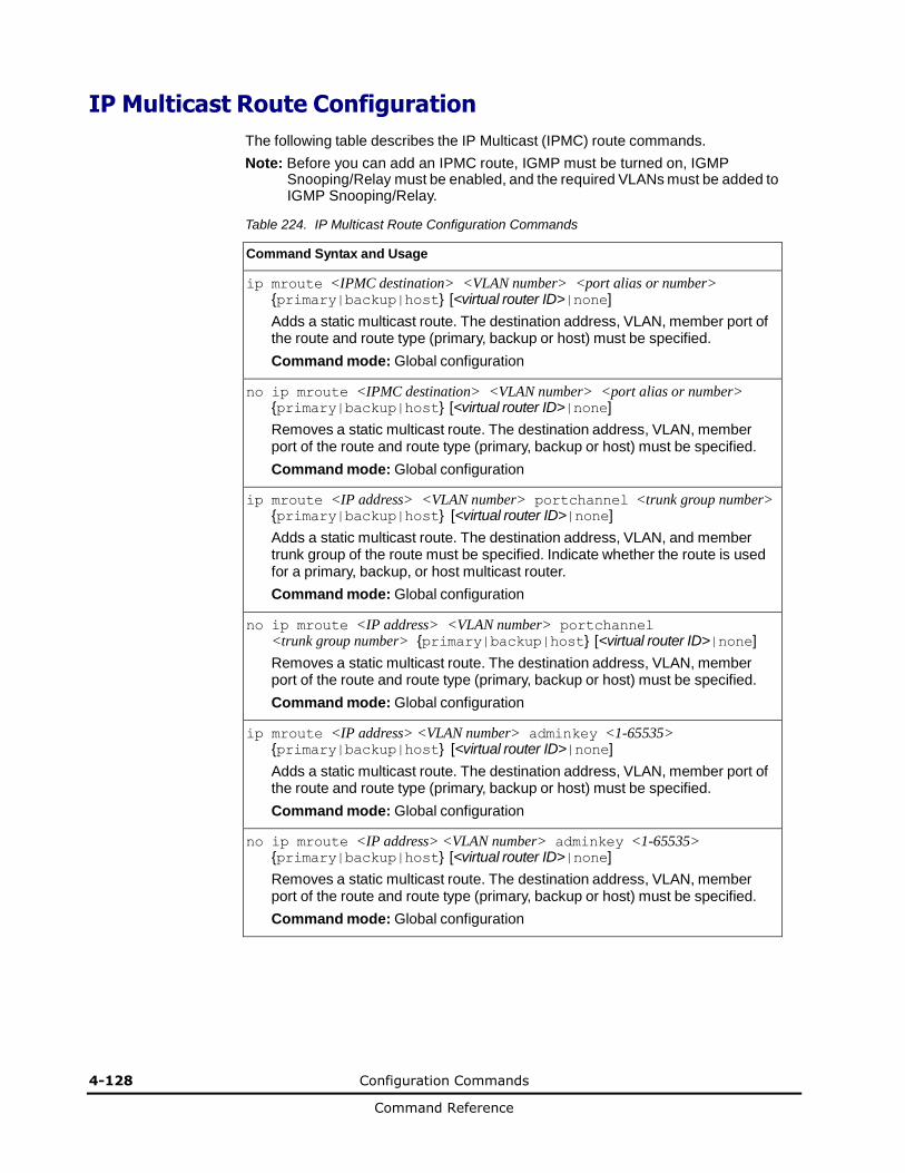
4-128 Configuration Commands
Command Reference
IP Multicast Route Configuration
The following table describes the IP Multicast (IPMC) route commands.
Note: Before you can add an IPMC route, IGMP must be turned on, IGMP Snooping/Relay must be enabled, and the required VLANs must be added to IGMP Snooping/Relay.
Table 224. IP Multicast Route Configuration Commands
Command Syntax and Usage
ip mroute <IPMC destination> <VLAN number> <port alias or number> {primary|backup|host} [<virtual router ID>|none]
Adds a static multicast route. The destination address, VLAN, member port of the route and route type (primary, backup or host) must be specified.
Command mode: Global configuration
no ip mroute <IPMC destination> <VLAN number> <port alias or number> {primary|backup|host} [<virtual router ID>|none]
Removes a static multicast route. The destination address, VLAN, member port of the route and route type (primary, backup or host) must be specified.
Command mode: Global configuration
ip mroute <IP address> <VLAN number> portchannel <trunk group number> {primary|backup|host} [<virtual router ID>|none]
Adds a static multicast route. The destination address, VLAN, and member trunk group of the route must be specified. Indicate whether the route is used for a primary, backup, or host multicast router.
Command mode: Global configuration
no ip mroute <IP address> <VLAN number> portchannel <trunk group number> {primary|backup|host} [<virtual router ID>|none]
Removes a static multicast route. The destination address, VLAN, member port of the route and route type (primary, backup or host) must be specified.
Command mode: Global configuration
ip mroute <IP address> <VLAN number> adminkey <1-65535> {primary|backup|host} [<virtual router ID>|none]
Adds a static multicast route. The destination address, VLAN, member port of the route and route type (primary, backup or host) must be specified.
Command mode: Global configuration
no ip mroute <IP address> <VLAN number> adminkey <1-65535> {primary|backup|host} [<virtual router ID>|none]
Removes a static multicast route. The destination address, VLAN, member port of the route and route type (primary, backup or host) must be specified.
Command mode: Global configuration
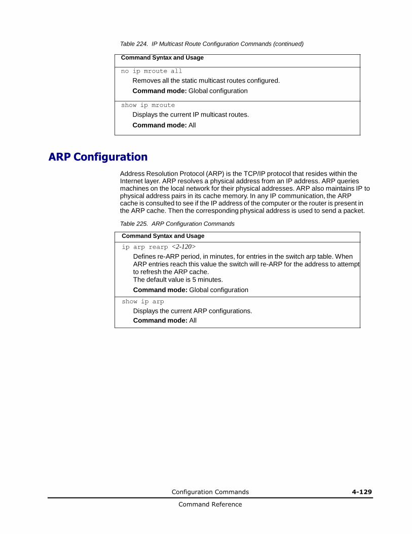
Configuration Commands 4-129
Command Reference
Table 224. IP Multicast Route Configuration Commands (continued)
Command Syntax and Usage
no ip mroute all
Removes all the static multicast routes configured.
Command mode: Global configuration
show ip mroute
Displays the current IP multicast routes.
Command mode: All
ARP Configuration
Address Resolution Protocol (ARP) is the TCP/IP protocol that resides within the Internet layer. ARP resolves a physical address from an IP address. ARP queries machines on the local network for their physical addresses. ARP also maintains IP to physical address pairs in its cache memory. In any IP communication, the ARP cache is consulted to see if the IP address of the computer or the router is present in the ARP cache. Then the corresponding physical address is used to send a packet.
Table 225. ARP Configuration Commands
Command Syntax and Usage
ip arp rearp <2-120>
Defines re-ARP period, in minutes, for entries in the switch arp table. When ARP entries reach this value the switch will re-ARP for the address to attempt to refresh the ARP cache. The default value is 5 minutes.
Command mode: Global configuration
show ip arp
Displays the current ARP configurations.
Command mode: All

4-130 Configuration Commands
Command Reference
ARP Static Configuration
Static ARP entries are permanent in the ARP cache and do not age out like the ARP entries that are learned dynamically. Static ARP entries enable the switch to reach the hosts without sending an ARP broadcast request to the network. Static ARPs are also useful to communicate with devices that do not respond to ARP requests. Static ARPs can also be configured on some gateways as a protection against malicious ARP Cache corruption and possible DOS attacks.
Table 226. ARP Static Configuration Commands
Command Syntax and Usage
ip arp <IP address> <MAC address> vlan <vlan number> port <port alias or number>
Adds a permanent ARP entry.
Command mode: Global configuration
ip arp <destination unicast IP address> <destination multicast MAC address> vlan <cluster vlan number>
Adds a static multicast ARP entry for Network Load Balancing (NLB).
Command mode: Global configuration
no ip arp <IP address>
Deletes a permanent ARP entry.
Command mode: Global configuration
no ip arp all
Deletes all static ARP entries.
Command mode: Global configuration
show ip arp static
Displays current static ARP configuration.
Command mode: All
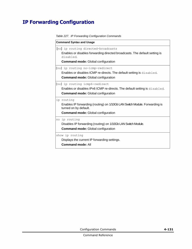
Configuration Commands 4-131
Command Reference
IP Forwarding Configuration
Table 227. IP Forwarding Configuration Commands
Command Syntax and Usage
[no] ip routing directed-broadcasts
Enables or disables forwarding directed broadcasts. The default setting is
disabled.
Command mode: Global configuration
[no] ip routing no-icmp-redirect
Enables or disables ICMP re-directs. The default setting is disabled.
Command mode: Global configuration
[no] ip routing icmp6-redirect
Enables or disables IPv6 ICMP re-directs. The default setting is disabled.
Command mode: Global configuration
ip routing
Enables IP forwarding (routing) on 1/10Gb LAN Switch Module. Forwarding is turned on by default.
Command mode: Global configuration
no ip routing
Disables IP forwarding (routing) on 1/10Gb LAN Switch Module.
Command mode: Global configuration
show ip routing
Displays the current IP forwarding settings.
Command mode: All

4-132 Configuration Commands
Command Reference
Network Filter Configuration
Table 228. IP Network Filter Configuration Commands
Command Syntax and Usage
ip match-address <1-256> <IP address> <IP netmask>
Sets the starting IP address and IP Netmask for this filter to define the range of IP addresses that will be accepted by the peer when the filter is enabled. The
default address is 0.0.0.0 0.0.0.0
For Border Gateway Protocol (BGP), assign the network filter to an access-list in a route map, then assign the route map to the peer.
Command mode: Global configuration.
ip match-address <1-256> enable
Enables the Network Filter configuration.
Command mode: Global configuration
no ip match-address <1-256> enable
Disables the Network Filter configuration.
Command mode: Global configuration
no ip match-address <1-256>
Deletes the Network Filter configuration.
Command mode: Global configuration
show ip match-address [<1-256>]
Displays the current the Network Filter configuration.
Command mode: All
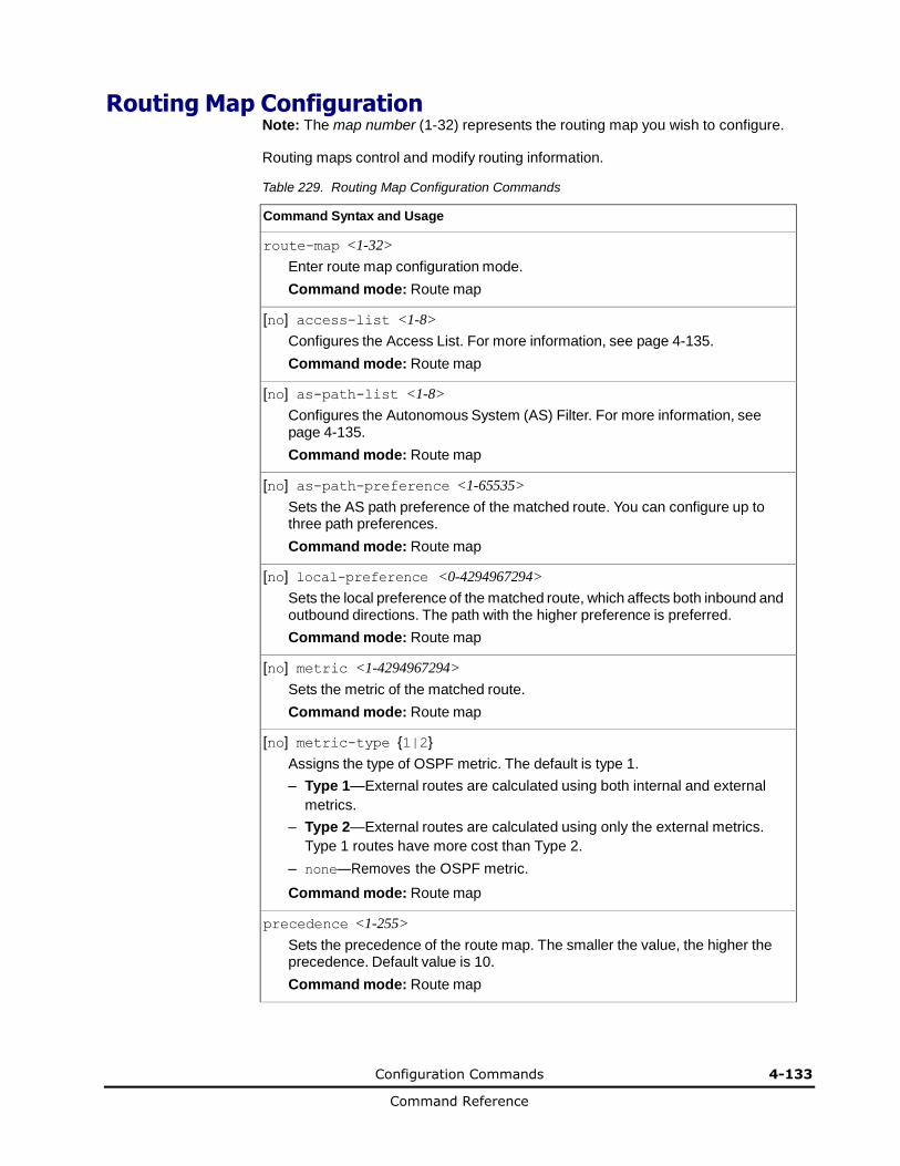
Configuration Commands 4-133
Command Reference
Routing Map Configuration Note: The map number (1-32) represents the routing map you wish to configure.
Routing maps control and modify routing information.
Table 229. Routing Map Configuration Commands
Command Syntax and Usage
route-map <1-32>
Enter route map configuration mode.
Command mode: Route map
[no] access-list <1-8>
Configures the Access List. For more information, see page 4-135.
Command mode: Route map
[no] as-path-list <1-8>
Configures the Autonomous System (AS) Filter. For more information, see page 4-135.
Command mode: Route map
[no] as-path-preference <1-65535>
Sets the AS path preference of the matched route. You can configure up to three path preferences.
Command mode: Route map
[no] local-preference <0-4294967294>
Sets the local preference of the matched route, which affects both inbound and outbound directions. The path with the higher preference is preferred.
Command mode: Route map
[no] metric <1-4294967294>
Sets the metric of the matched route.
Command mode: Route map
[no] metric-type {1|2}
Assigns the type of OSPF metric. The default is type 1.
– Type 1—External routes are calculated using both internal and external
metrics.
– Type 2—External routes are calculated using only the external metrics.
Type 1 routes have more cost than Type 2.
– none—Removes the OSPF metric.
Command mode: Route map
precedence <1-255>
Sets the precedence of the route map. The smaller the value, the higher the precedence. Default value is 10.
Command mode: Route map
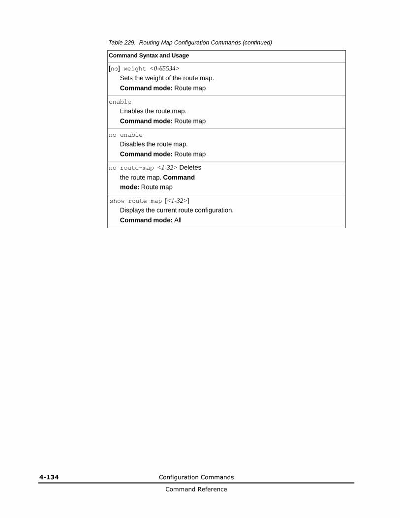
4-134 Configuration Commands
Command Reference
Table 229. Routing Map Configuration Commands (continued)
Command Syntax and Usage
[no] weight <0-65534>
Sets the weight of the route map.
Command mode: Route map
enable
Enables the route map.
Command mode: Route map
no enable
Disables the route map.
Command mode: Route map
no route-map <1-32> Deletes
the route map. Command
mode: Route map
show route-map [<1-32>]
Displays the current route configuration.
Command mode: All
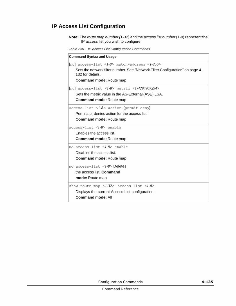
Configuration Commands 4-135
Command Reference
IP Access List Configuration
Note: The route map number (1-32) and the access list number (1-8) represent the IP access list you wish to configure.
Table 230. IP Access List Configuration Commands
Command Syntax and Usage
[no] access-list <1-8> match-address <1-256>
Sets the network filter number. See “Network Filter Configuration” on page 4-132 for details.
Command mode: Route map
[no] access-list <1-8> metric <1-4294967294>
Sets the metric value in the AS-External (ASE) LSA.
Command mode: Route map
access-list <1-8> action {permit|deny}
Permits or denies action for the access list.
Command mode: Route map
access-list <1-8> enable
Enables the access list.
Command mode: Route map
no access-list <1-8> enable
Disables the access list.
Command mode: Route map
no access-list <1-8> Deletes
the access list. Command
mode: Route map
show route-map <1-32> access-list <1-8>
Displays the current Access List configuration.
Command mode: All
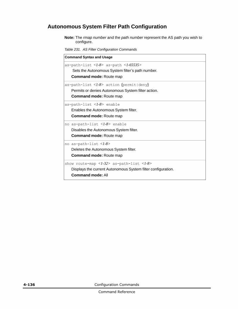
4-136 Configuration Commands
Command Reference
Autonomous System Filter Path Configuration
Note: The rmap number and the path number represent the AS path you wish to configure.
Table 231. AS Filter Configuration Commands
Command Syntax and Usage
as-path-list <1-8> as-path <1-65535>
Sets the Autonomous System filter’s path number.
Command mode: Route map
as-path-list <1-8> action {permit|deny}
Permits or denies Autonomous System filter action.
Command mode: Route map
as-path-list <1-8> enable
Enables the Autonomous System filter.
Command mode: Route map
no as-path-list <1-8> enable
Disables the Autonomous System filter.
Command mode: Route map
no as-path-list <1-8>
Deletes the Autonomous System filter.
Command mode: Route map
show route-map <1-32> as-path-list <1-8>
Displays the current Autonomous System filter configuration.
Command mode: All
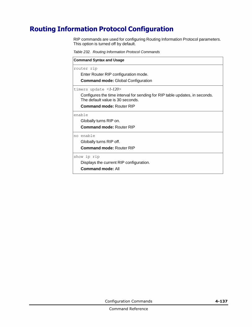
Configuration Commands 4-137
Command Reference
Routing Information Protocol Configuration
RIP commands are used for configuring Routing Information Protocol parameters. This option is turned off by default.
Table 232. Routing Information Protocol Commands
Command Syntax and Usage
router rip
Enter Router RIP configuration mode.
Command mode: Global Configuration
timers update <1-120>
Configures the time interval for sending for RIP table updates, in seconds. The default value is 30 seconds.
Command mode: Router RIP
enable
Globally turns RIP on.
Command mode: Router RIP
no enable
Globally turns RIP off.
Command mode: Router RIP
show ip rip
Displays the current RIP configuration.
Command mode: All
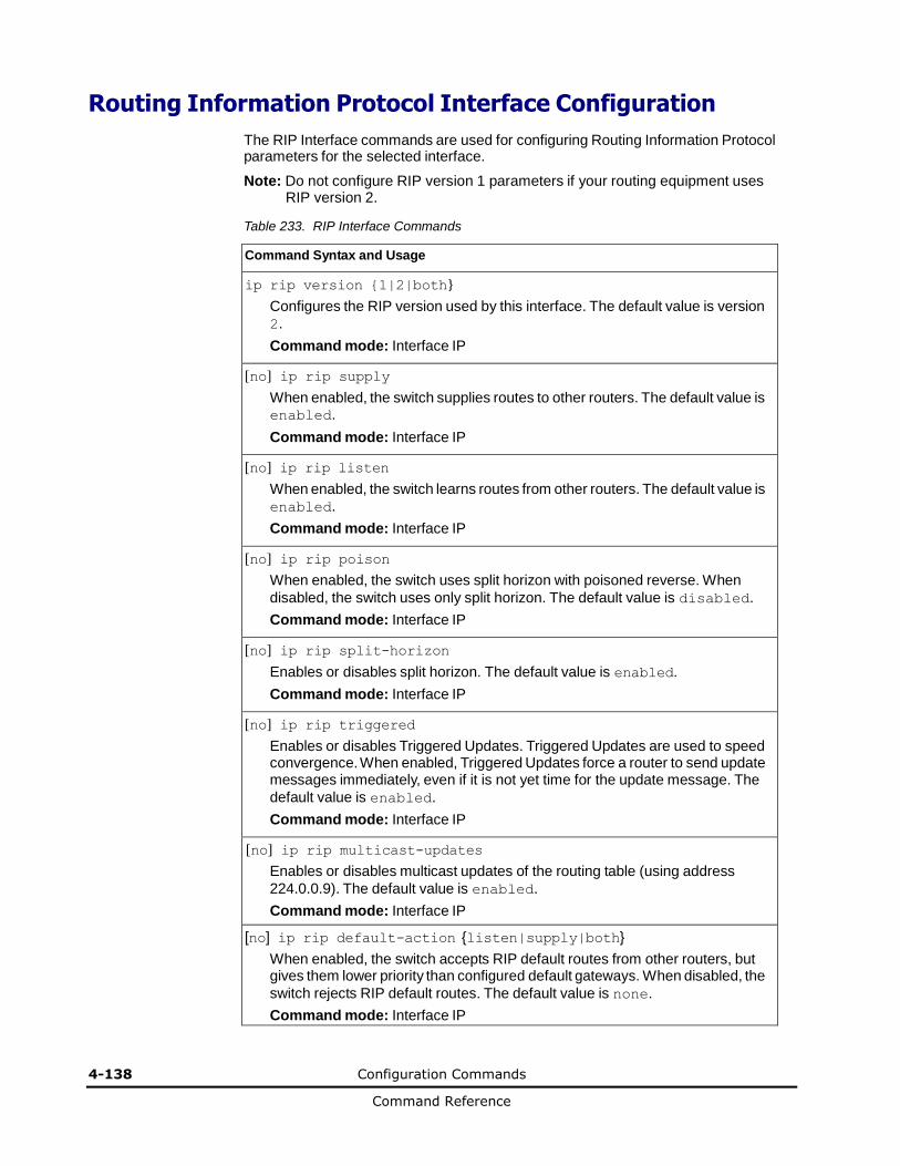
4-138 Configuration Commands
Command Reference
Routing Information Protocol Interface Configuration
The RIP Interface commands are used for configuring Routing Information Protocol parameters for the selected interface.
Note: Do not configure RIP version 1 parameters if your routing equipment uses RIP version 2.
Table 233. RIP Interface Commands
Command Syntax and Usage
ip rip version {1|2|both}
Configures the RIP version used by this interface. The default value is version
2.
Command mode: Interface IP
[no] ip rip supply
When enabled, the switch supplies routes to other routers. The default value is enabled.
Command mode: Interface IP
[no] ip rip listen
When enabled, the switch learns routes from other routers. The default value is
enabled.
Command mode: Interface IP
[no] ip rip poison
When enabled, the switch uses split horizon with poisoned reverse. When
disabled, the switch uses only split horizon. The default value is disabled.
Command mode: Interface IP
[no] ip rip split-horizon
Enables or disables split horizon. The default value is enabled.
Command mode: Interface IP
[no] ip rip triggered
Enables or disables Triggered Updates. Triggered Updates are used to speed convergence. When enabled, Triggered Updates force a router to send update messages immediately, even if it is not yet time for the update message. The
default value is enabled.
Command mode: Interface IP
[no] ip rip multicast-updates
Enables or disables multicast updates of the routing table (using address
224.0.0.9). The default value is enabled.
Command mode: Interface IP
[no] ip rip default-action {listen|supply|both}
When enabled, the switch accepts RIP default routes from other routers, but gives them lower priority than configured default gateways. When disabled, the
switch rejects RIP default routes. The default value is none.
Command mode: Interface IP
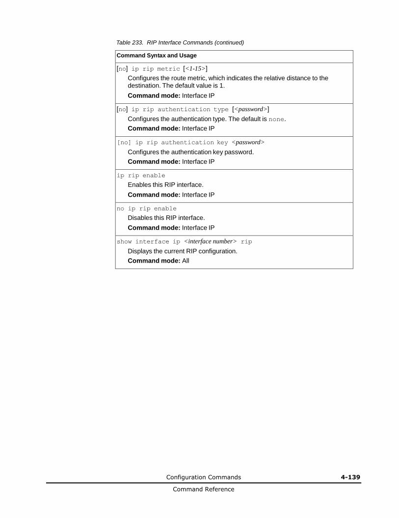
Configuration Commands 4-139
Command Reference
Table 233. RIP Interface Commands (continued)
Command Syntax and Usage
[no] ip rip metric [<1-15>]
Configures the route metric, which indicates the relative distance to the destination. The default value is 1.
Command mode: Interface IP
[no] ip rip authentication type [<password>]
Configures the authentication type. The default is none.
Command mode: Interface IP
[no] ip rip authentication key <password>
Configures the authentication key password.
Command mode: Interface IP
ip rip enable
Enables this RIP interface.
Command mode: Interface IP
no ip rip enable
Disables this RIP interface.
Command mode: Interface IP
show interface ip <interface number> rip
Displays the current RIP configuration.
Command mode: All
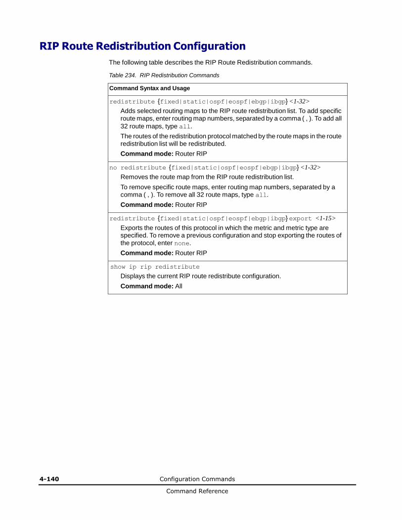
4-140 Configuration Commands
Command Reference
RIP Route Redistribution Configuration
The following table describes the RIP Route Redistribution commands.
Table 234. RIP Redistribution Commands
Command Syntax and Usage
redistribute {fixed|static|ospf|eospf|ebgp|ibgp} <1-32>
Adds selected routing maps to the RIP route redistribution list. To add specific route maps, enter routing map numbers, separated by a comma ( , ). To add all
32 route maps, type all.
The routes of the redistribution protocol matched by the route maps in the route redistribution list will be redistributed.
Command mode: Router RIP
no redistribute {fixed|static|ospf|eospf|ebgp|ibgp} <1-32>
Removes the route map from the RIP route redistribution list.
To remove specific route maps, enter routing map numbers, separated by a comma ( , ). To remove all 32 route maps, type all.
Command mode: Router RIP
redistribute {fixed|static|ospf|eospf|ebgp|ibgp} export <1-15>
Exports the routes of this protocol in which the metric and metric type are specified. To remove a previous configuration and stop exporting the routes of the protocol, enter none.
Command mode: Router RIP
show ip rip redistribute
Displays the current RIP route redistribute configuration.
Command mode: All
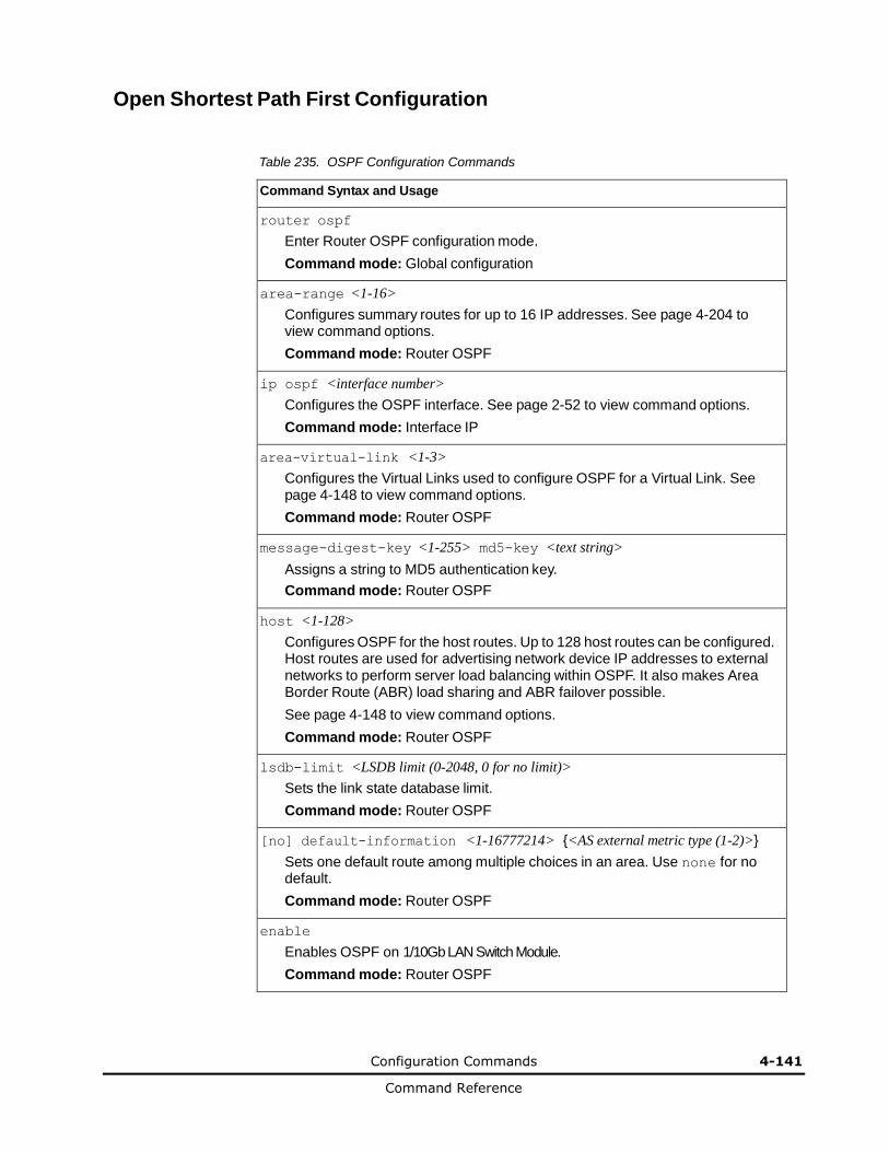
Configuration Commands 4-141
Command Reference
Open Shortest Path First Configuration
Table 235. OSPF Configuration Commands
Command Syntax and Usage
router ospf
Enter Router OSPF configuration mode.
Command mode: Global configuration
area-range <1-16>
Configures summary routes for up to 16 IP addresses. See page 4-204 to view command options.
Command mode: Router OSPF
ip ospf <interface number>
Configures the OSPF interface. See page 2-52 to view command options.
Command mode: Interface IP
area-virtual-link <1-3>
Configures the Virtual Links used to configure OSPF for a Virtual Link. See page 4-148 to view command options.
Command mode: Router OSPF
message-digest-key <1-255> md5-key <text string>
Assigns a string to MD5 authentication key.
Command mode: Router OSPF
host <1-128>
Configures OSPF for the host routes. Up to 128 host routes can be configured. Host routes are used for advertising network device IP addresses to external networks to perform server load balancing within OSPF. It also makes Area Border Route (ABR) load sharing and ABR failover possible.
See page 4-148 to view command options.
Command mode: Router OSPF
lsdb-limit <LSDB limit (0-2048, 0 for no limit)>
Sets the link state database limit.
Command mode: Router OSPF
[no] default-information <1-16777214> {<AS external metric type (1-2)>}
Sets one default route among multiple choices in an area. Use none for no default.
Command mode: Router OSPF
enable
Enables OSPF on 1/10Gb LAN Switch Module.
Command mode: Router OSPF
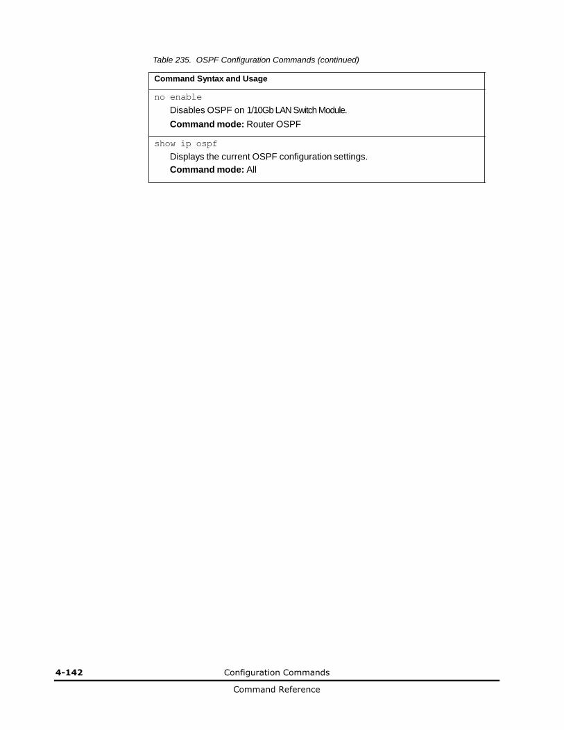
4-142 Configuration Commands
Command Reference
Table 235. OSPF Configuration Commands (continued)
Command Syntax and Usage
no enable
Disables OSPF on 1/10Gb LAN Switch Module.
Command mode: Router OSPF
show ip ospf
Displays the current OSPF configuration settings.
Command mode: All
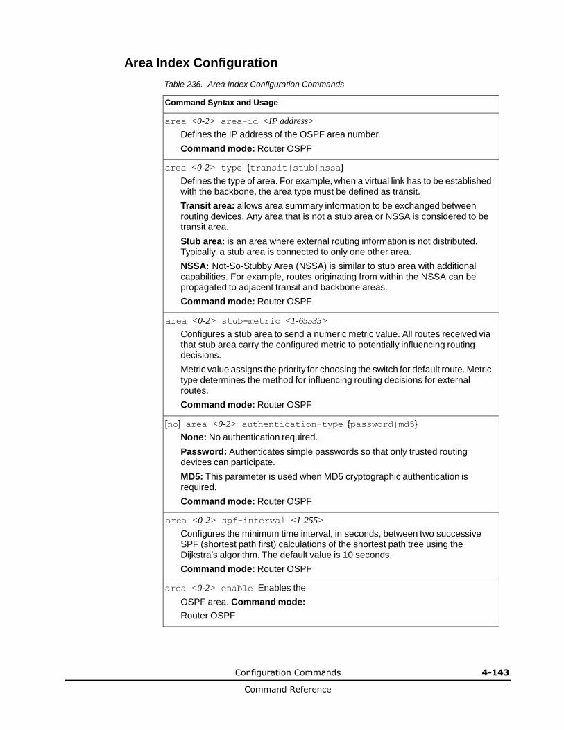
Configuration Commands 4-143
Command Reference
Area Index Configuration Table 236. Area Index Configuration Commands
Command Syntax and Usage
area <0-2> area-id <IP address>
Defines the IP address of the OSPF area number.
Command mode: Router OSPF
area <0-2> type {transit|stub|nssa}
Defines the type of area. For example, when a virtual link has to be established with the backbone, the area type must be defined as transit.
Transit area: allows area summary information to be exchanged between routing devices. Any area that is not a stub area or NSSA is considered to be transit area.
Stub area: is an area where external routing information is not distributed. Typically, a stub area is connected to only one other area.
NSSA: Not-So-Stubby Area (NSSA) is similar to stub area with additional capabilities. For example, routes originating from within the NSSA can be propagated to adjacent transit and backbone areas.
Command mode: Router OSPF
area <0-2> stub-metric <1-65535>
Configures a stub area to send a numeric metric value. All routes received via that stub area carry the configured metric to potentially influencing routing decisions.
Metric value assigns the priority for choosing the switch for default route. Metric type determines the method for influencing routing decisions for external routes.
Command mode: Router OSPF
[no] area <0-2> authentication-type {password|md5}
None: No authentication required.
Password: Authenticates simple passwords so that only trusted routing devices can participate.
MD5: This parameter is used when MD5 cryptographic authentication is required.
Command mode: Router OSPF
area <0-2> spf-interval <1-255>
Configures the minimum time interval, in seconds, between two successive SPF (shortest path first) calculations of the shortest path tree using the Dijkstra’s algorithm. The default value is 10 seconds.
Command mode: Router OSPF
area <0-2> enable Enables the
OSPF area. Command mode:
Router OSPF
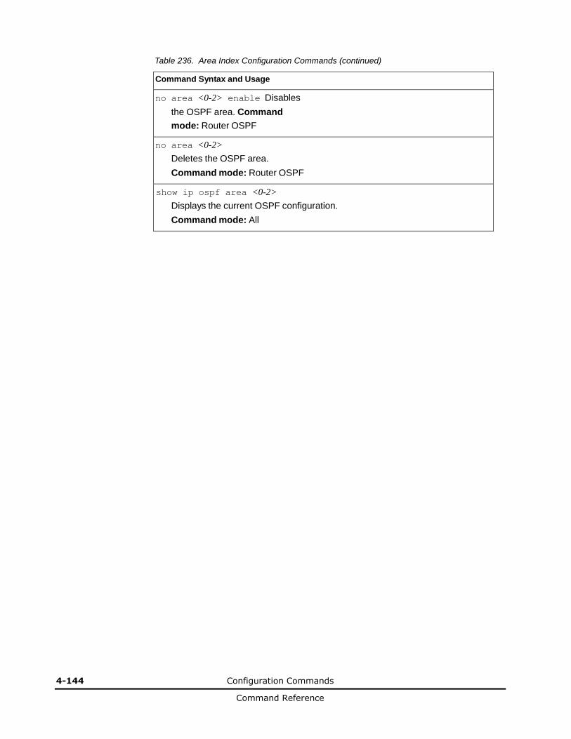
4-144 Configuration Commands
Command Reference
Table 236. Area Index Configuration Commands (continued)
Command Syntax and Usage
no area <0-2> enable Disables
the OSPF area. Command
mode: Router OSPF
no area <0-2>
Deletes the OSPF area.
Command mode: Router OSPF
show ip ospf area <0-2>
Displays the current OSPF configuration.
Command mode: All
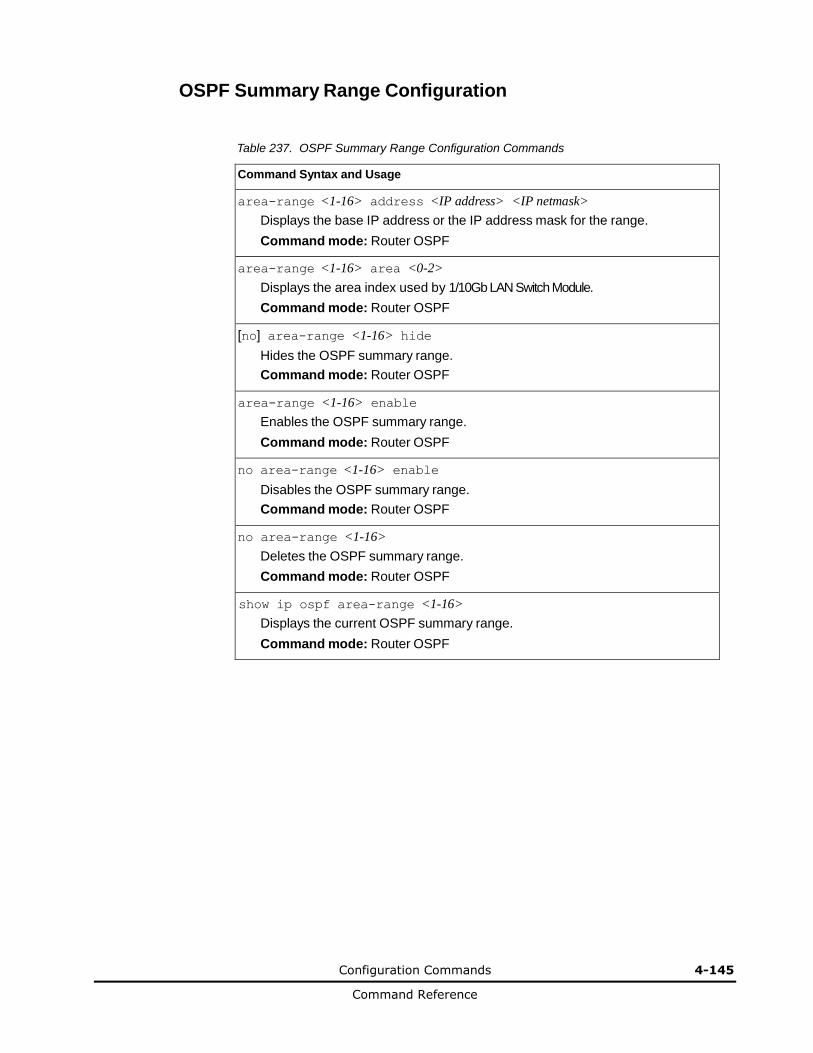
Configuration Commands 4-145
Command Reference
OSPF Summary Range Configuration
Table 237. OSPF Summary Range Configuration Commands
Command Syntax and Usage
area-range <1-16> address <IP address> <IP netmask>
Displays the base IP address or the IP address mask for the range.
Command mode: Router OSPF
area-range <1-16> area <0-2>
Displays the area index used by 1/10Gb LAN Switch Module.
Command mode: Router OSPF
[no] area-range <1-16> hide
Hides the OSPF summary range.
Command mode: Router OSPF
area-range <1-16> enable
Enables the OSPF summary range.
Command mode: Router OSPF
no area-range <1-16> enable
Disables the OSPF summary range.
Command mode: Router OSPF
no area-range <1-16>
Deletes the OSPF summary range.
Command mode: Router OSPF
show ip ospf area-range <1-16>
Displays the current OSPF summary range.
Command mode: Router OSPF
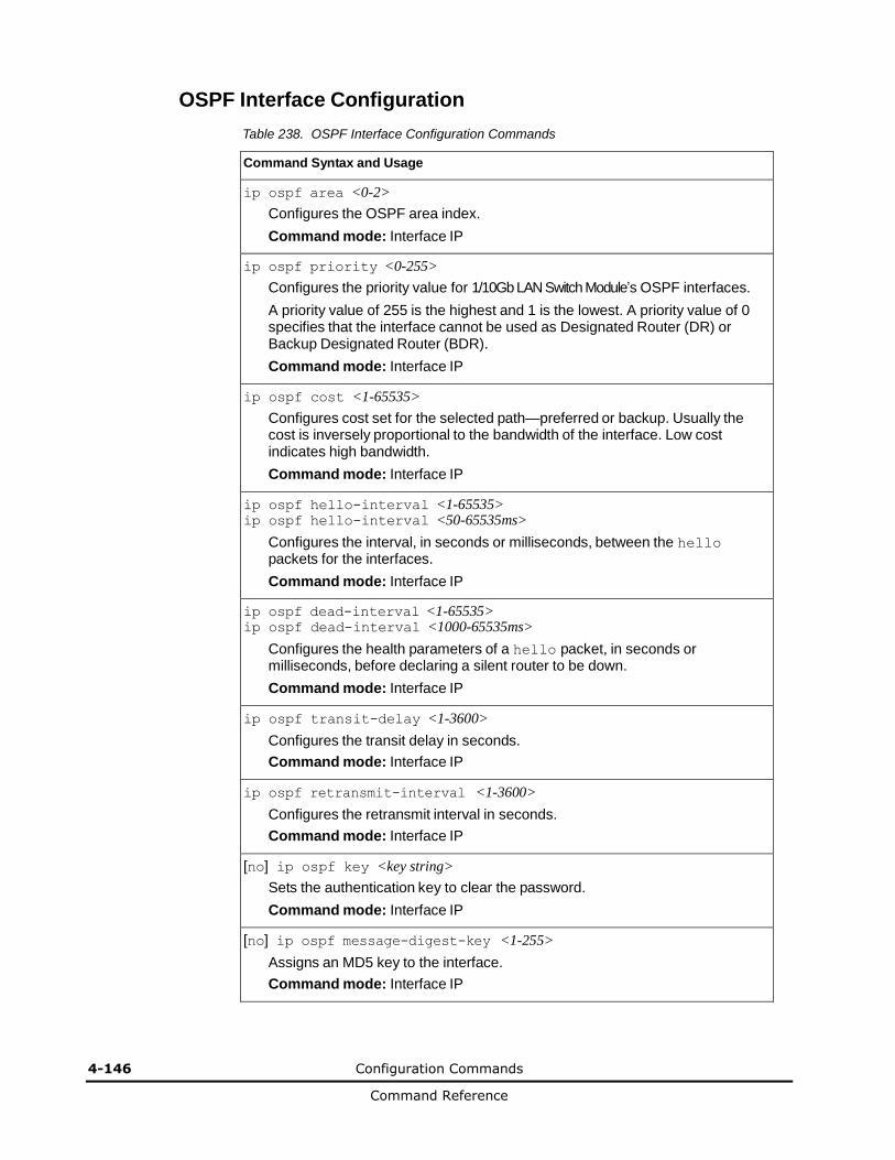
4-146 Configuration Commands
Command Reference
OSPF Interface Configuration Table 238. OSPF Interface Configuration Commands
Command Syntax and Usage
ip ospf area <0-2>
Configures the OSPF area index.
Command mode: Interface IP
ip ospf priority <0-255>
Configures the priority value for 1/10Gb LAN Switch Module’s OSPF interfaces.
A priority value of 255 is the highest and 1 is the lowest. A priority value of 0 specifies that the interface cannot be used as Designated Router (DR) or Backup Designated Router (BDR).
Command mode: Interface IP
ip ospf cost <1-65535>
Configures cost set for the selected path—preferred or backup. Usually the cost is inversely proportional to the bandwidth of the interface. Low cost indicates high bandwidth.
Command mode: Interface IP
ip ospf hello-interval <1-65535> ip ospf hello-interval <50-65535ms>
Configures the interval, in seconds or milliseconds, between the hello packets for the interfaces.
Command mode: Interface IP
ip ospf dead-interval <1-65535> ip ospf dead-interval <1000-65535ms>
Configures the health parameters of a hello packet, in seconds or milliseconds, before declaring a silent router to be down.
Command mode: Interface IP
ip ospf transit-delay <1-3600>
Configures the transit delay in seconds.
Command mode: Interface IP
ip ospf retransmit-interval <1-3600>
Configures the retransmit interval in seconds.
Command mode: Interface IP
[no] ip ospf key <key string>
Sets the authentication key to clear the password.
Command mode: Interface IP
[no] ip ospf message-digest-key <1-255>
Assigns an MD5 key to the interface.
Command mode: Interface IP
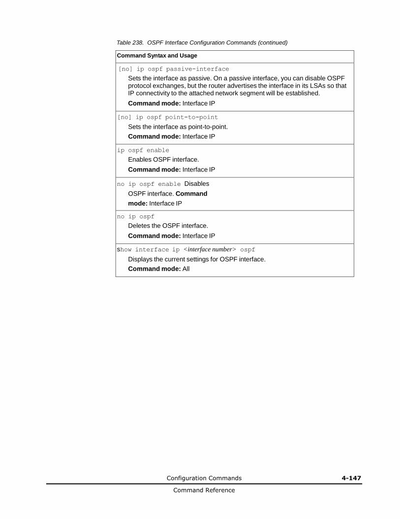
Configuration Commands 4-147
Command Reference
Table 238. OSPF Interface Configuration Commands (continued)
Command Syntax and Usage
[no] ip ospf passive-interface
Sets the interface as passive. On a passive interface, you can disable OSPF protocol exchanges, but the router advertises the interface in its LSAs so that IP connectivity to the attached network segment will be established.
Command mode: Interface IP
[no] ip ospf point-to-point
Sets the interface as point-to-point.
Command mode: Interface IP
ip ospf enable
Enables OSPF interface.
Command mode: Interface IP
no ip ospf enable Disables
OSPF interface. Command
mode: Interface IP
no ip ospf
Deletes the OSPF interface.
Command mode: Interface IP
show interface ip <interface number> ospf
Displays the current settings for OSPF interface.
Command mode: All
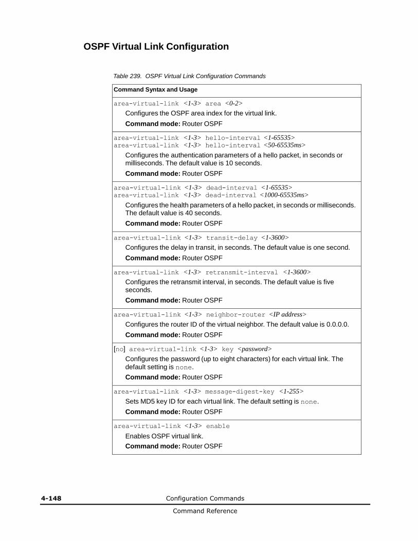
4-148 Configuration Commands
Command Reference
OSPF Virtual Link Configuration
Table 239. OSPF Virtual Link Configuration Commands
Command Syntax and Usage
area-virtual-link <1-3> area <0-2>
Configures the OSPF area index for the virtual link.
Command mode: Router OSPF
area-virtual-link <1-3> hello-interval <1-65535> area-virtual-link <1-3> hello-interval <50-65535ms>
Configures the authentication parameters of a hello packet, in seconds or milliseconds. The default value is 10 seconds.
Command mode: Router OSPF
area-virtual-link <1-3> dead-interval <1-65535> area-virtual-link <1-3> dead-interval <1000-65535ms>
Configures the health parameters of a hello packet, in seconds or milliseconds. The default value is 40 seconds.
Command mode: Router OSPF
area-virtual-link <1-3> transit-delay <1-3600>
Configures the delay in transit, in seconds. The default value is one second.
Command mode: Router OSPF
area-virtual-link <1-3> retransmit-interval <1-3600>
Configures the retransmit interval, in seconds. The default value is five seconds.
Command mode: Router OSPF
area-virtual-link <1-3> neighbor-router <IP address>
Configures the router ID of the virtual neighbor. The default value is 0.0.0.0.
Command mode: Router OSPF
[no] area-virtual-link <1-3> key <password>
Configures the password (up to eight characters) for each virtual link. The
default setting is none.
Command mode: Router OSPF
area-virtual-link <1-3> message-digest-key <1-255>
Sets MD5 key ID for each virtual link. The default setting is none.
Command mode: Router OSPF
area-virtual-link <1-3> enable
Enables OSPF virtual link.
Command mode: Router OSPF
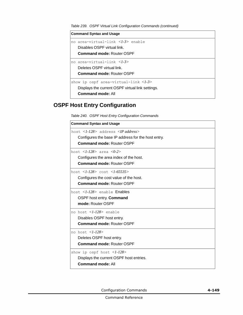
Configuration Commands 4-149
Command Reference
Table 239. OSPF Virtual Link Configuration Commands (continued)
Command Syntax and Usage
no area-virtual-link <1-3> enable
Disables OSPF virtual link.
Command mode: Router OSPF
no area-virtual-link <1-3>
Deletes OSPF virtual link.
Command mode: Router OSPF
show ip ospf area-virtual-link <1-3>
Displays the current OSPF virtual link settings.
Command mode: All
OSPF Host Entry Configuration
Table 240. OSPF Host Entry Configuration Commands
Command Syntax and Usage
host <1-128> address <IP address>
Configures the base IP address for the host entry.
Command mode: Router OSPF
host <1-128> area <0-2>
Configures the area index of the host.
Command mode: Router OSPF
host <1-128> cost <1-65535>
Configures the cost value of the host.
Command mode: Router OSPF
host <1-128> enable Enables
OSPF host entry. Command
mode: Router OSPF
no host <1-128> enable
Disables OSPF host entry.
Command mode: Router OSPF
no host <1-128>
Deletes OSPF host entry.
Command mode: Router OSPF
show ip ospf host <1-128>
Displays the current OSPF host entries.
Command mode: All
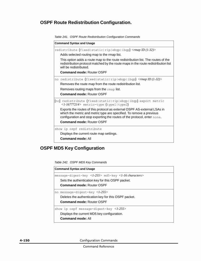
4-150 Configuration Commands
Command Reference
OSPF Route Redistribution Configuration.
Table 241. OSPF Route Redistribution Configuration Commands
Command Syntax and Usage
redistribute {fixed|static|rip|ebgp|ibgp} <rmap ID (1-32)>
Adds selected routing map to the rmap list.
This option adds a route map to the route redistribution list. The routes of the redistribution protocol matched by the route maps in the route redistribution list will be redistributed.
Command mode: Router OSPF
no redistribute {fixed|static|rip|ebgp|ibgp} <rmap ID (1-32)>
Removes the route map from the route redistribution list.
Removes routing maps from the rmap list.
Command mode: Router OSPF
[no] redistribute {fixed|static|rip|ebgp|ibgp} export metric <1-16777214> metric-type {type1|type2}
Exports the routes of this protocol as external OSPF AS-external LSAs in which the metric and metric type are specified. To remove a previous
configuration and stop exporting the routes of the protocol, enter none.
Command mode: Router OSPF
show ip ospf redistribute
Displays the current route map settings.
Command mode: All
OSPF MD5 Key Configuration
Table 242. OSPF MD5 Key Commands
Command Syntax and Usage
message-digest-key <1-255> md5-key <1-16 characters>
Sets the authentication key for this OSPF packet.
Command mode: Router OSPF
no message-digest-key <1-255>
Deletes the authentication key for this OSPF packet.
Command mode: Router OSPF
show ip ospf message-digest-key <1-255>
Displays the current MD5 key configuration.
Command mode: All
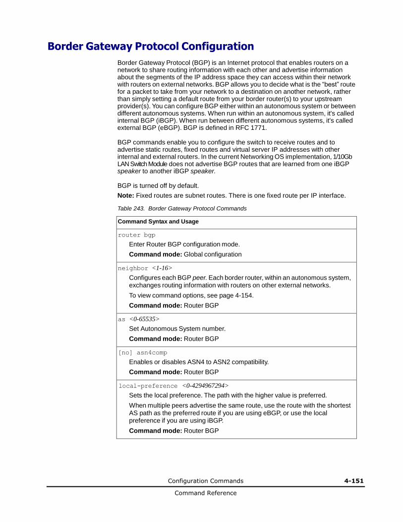
Configuration Commands 4-151
Command Reference
Border Gateway Protocol Configuration
Border Gateway Protocol (BGP) is an Internet protocol that enables routers on a network to share routing information with each other and advertise information about the segments of the IP address space they can access within their network with routers on external networks. BGP allows you to decide what is the “best” route for a packet to take from your network to a destination on another network, rather than simply setting a default route from your border router(s) to your upstream provider(s). You can configure BGP either within an autonomous system or between different autonomous systems. When run within an autonomous system, it's called internal BGP (iBGP). When run between different autonomous systems, it's called external BGP (eBGP). BGP is defined in RFC 1771.
BGP commands enable you to configure the switch to receive routes and to advertise static routes, fixed routes and virtual server IP addresses with other internal and external routers. In the current Networking OS implementation, 1/10Gb LAN Switch Module does not advertise BGP routes that are learned from one iBGP speaker to another iBGP speaker.
BGP is turned off by default.
Note: Fixed routes are subnet routes. There is one fixed route per IP interface.
Table 243. Border Gateway Protocol Commands
Command Syntax and Usage
router bgp
Enter Router BGP configuration mode.
Command mode: Global configuration
neighbor <1-16>
Configures each BGP peer. Each border router, within an autonomous system, exchanges routing information with routers on other external networks.
To view command options, see page 4-154.
Command mode: Router BGP
as <0-65535>
Set Autonomous System number.
Command mode: Router BGP
[no] asn4comp
Enables or disables ASN4 to ASN2 compatibility.
Command mode: Router BGP
local-preference <0-4294967294>
Sets the local preference. The path with the higher value is preferred.
When multiple peers advertise the same route, use the route with the shortest AS path as the preferred route if you are using eBGP, or use the local preference if you are using iBGP.
Command mode: Router BGP

4-152 Configuration Commands
Command Reference
Table 243. Border Gateway Protocol Commands (continued)
Command Syntax and Usage
enable
Globally turns BGP on.
Command mode: Router BGP
no enable
Globally turns BGP off.
Command mode: Router BGP
show ip bgp
Displays the current BGP configuration.
Command mode: All
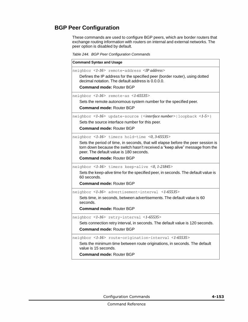
Configuration Commands 4-153
Command Reference
BGP Peer Configuration
These commands are used to configure BGP peers, which are border routers that exchange routing information with routers on internal and external networks. The peer option is disabled by default.
Table 244. BGP Peer Configuration Commands
Command Syntax and Usage
neighbor <1-16> remote-address <IP address>
Defines the IP address for the specified peer (border router), using dotted decimal notation. The default address is 0.0.0.0.
Command mode: Router BGP
neighbor <1-16> remote-as <1-65535>
Sets the remote autonomous system number for the specified peer.
Command mode: Router BGP
neighbor <1-16> update-source {<interface number>|loopback <1-5>}
Sets the source interface number for this peer.
Command mode: Router BGP
neighbor <1-16> timers hold-time <0, 3-65535>
Sets the period of time, in seconds, that will elapse before the peer session is torn down because the switch hasn’t received a “keep alive” message from the peer. The default value is 180 seconds.
Command mode: Router BGP
neighbor <1-16> timers keep-alive <0, 1-21845>
Sets the keep-alive time for the specified peer, in seconds. The default value is 60 seconds.
Command mode: Router BGP
neighbor <1-16> advertisement-interval <1-65535>
Sets time, in seconds, between advertisements. The default value is 60 seconds.
Command mode: Router BGP
neighbor <1-16> retry-interval <1-65535>
Sets connection retry interval, in seconds. The default value is 120 seconds.
Command mode: Router BGP
neighbor <1-16> route-origination-interval <1-65535>
Sets the minimum time between route originations, in seconds. The default value is 15 seconds.
Command mode: Router BGP
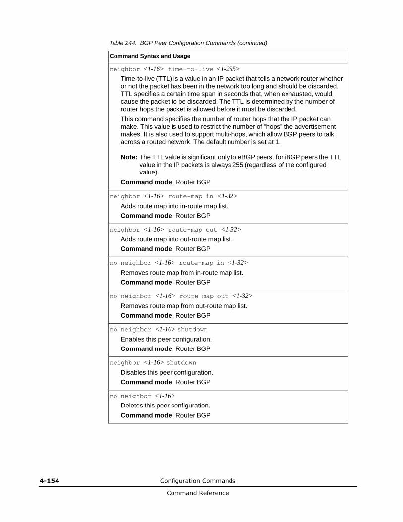
4-154 Configuration Commands
Command Reference
Table 244. BGP Peer Configuration Commands (continued)
Command Syntax and Usage
neighbor <1-16> time-to-live <1-255>
Time-to-live (TTL) is a value in an IP packet that tells a network router whether or not the packet has been in the network too long and should be discarded. TTL specifies a certain time span in seconds that, when exhausted, would cause the packet to be discarded. The TTL is determined by the number of router hops the packet is allowed before it must be discarded.
This command specifies the number of router hops that the IP packet can make. This value is used to restrict the number of “hops” the advertisement makes. It is also used to support multi-hops, which allow BGP peers to talk across a routed network. The default number is set at 1.
Note: The TTL value is significant only to eBGP peers, for iBGP peers the TTL
value in the IP packets is always 255 (regardless of the configured value).
Command mode: Router BGP
neighbor <1-16> route-map in <1-32>
Adds route map into in-route map list.
Command mode: Router BGP
neighbor <1-16> route-map out <1-32>
Adds route map into out-route map list.
Command mode: Router BGP
no neighbor <1-16> route-map in <1-32>
Removes route map from in-route map list.
Command mode: Router BGP
no neighbor <1-16> route-map out <1-32>
Removes route map from out-route map list.
Command mode: Router BGP
no neighbor <1-16> shutdown
Enables this peer configuration.
Command mode: Router BGP
neighbor <1-16> shutdown
Disables this peer configuration.
Command mode: Router BGP
no neighbor <1-16>
Deletes this peer configuration.
Command mode: Router BGP
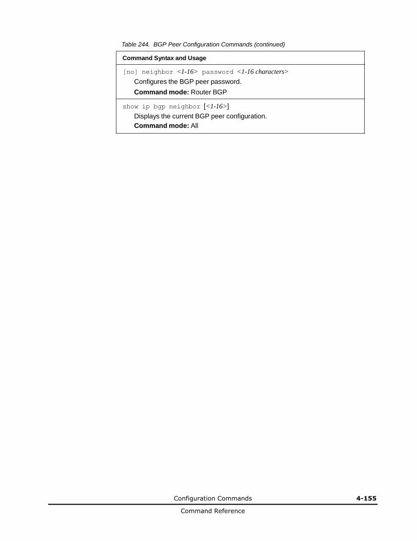
Configuration Commands 4-155
Command Reference
Table 244. BGP Peer Configuration Commands (continued)
Command Syntax and Usage
[no] neighbor <1-16> password <1-16 characters>
Configures the BGP peer password.
Command mode: Router BGP
show ip bgp neighbor [<1-16>]
Displays the current BGP peer configuration.
Command mode: All

4-156 Configuration Commands
Command Reference
BGP Redistribution Configuration
Table 245. BGP Redistribution Configuration Commands
Command Syntax and Usage
[no] neighbor <1-16> redistribute default-metric <1-4294967294>
Sets default metric of advertised routes.
Command mode: Router BGP
[no] neighbor <1-16> redistribute default-action {import|originate|redistribute}
Sets default route action.
Defaults routes can be configured as import, originate, redistribute, or none.
None: No routes are configured
Import: Import these routes.
Originate: The switch sends a default route to peers if it does not have any default routes in its routing table.
Redistribute: Default routes are either configured through default gateway or learned through other protocols and redistributed to peer. If the routes are learned from default gateway configuration, you have to enable static routes since the routes from default gateway are static routes. Similarly, if the routes are learned from a certain routing protocol, you have to enable that protocol.
Command mode: Router BGP
[no] neighbor <1-16> redistribute rip
Enables or disables advertising RIP routes.
Command mode: Router BGP
[no] neighbor <1-16> redistribute ospf
Enables or disables advertising OSPF routes.
Command mode: Router BGP
[no] neighbor <1-16> redistribute fixed
Enables or disables advertising fixed routes.
Command mode: Router BGP
[no] neighbor <1-16> redistribute static
Enables or disables advertising static routes.
Command mode: Router BGP
show ip bgp neighbor <1-16> redistribute
Displays current redistribution configuration.
Command mode: All
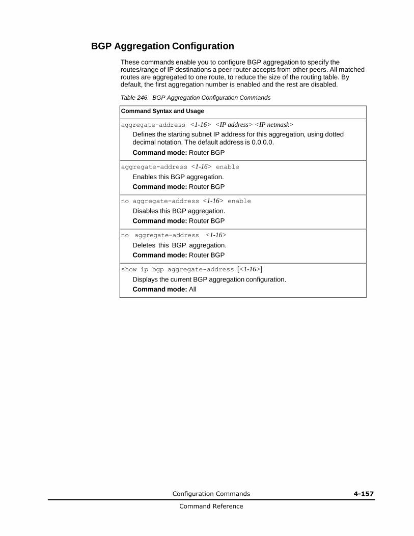
Configuration Commands 4-157
Command Reference
BGP Aggregation Configuration
These commands enable you to configure BGP aggregation to specify the routes/range of IP destinations a peer router accepts from other peers. All matched routes are aggregated to one route, to reduce the size of the routing table. By default, the first aggregation number is enabled and the rest are disabled.
Table 246. BGP Aggregation Configuration Commands
Command Syntax and Usage
aggregate-address <1-16> <IP address> <IP netmask>
Defines the starting subnet IP address for this aggregation, using dotted decimal notation. The default address is 0.0.0.0.
Command mode: Router BGP
aggregate-address <1-16> enable
Enables this BGP aggregation.
Command mode: Router BGP
no aggregate-address <1-16> enable
Disables this BGP aggregation.
Command mode: Router BGP
no aggregate-address <1-16>
Deletes this BGP aggregation.
Command mode: Router BGP
show ip bgp aggregate-address [<1-16>]
Displays the current BGP aggregation configuration.
Command mode: All
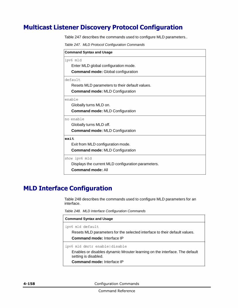
4-158 Configuration Commands
Command Reference
Multicast Listener Discovery Protocol Configuration
Table 247 describes the commands used to configure MLD parameters..
Table 247. MLD Protocol Configuration Commands
Command Syntax and Usage
ipv6 mld
Enter MLD global configuration mode.
Command mode: Global configuration
default
Resets MLD parameters to their default values.
Command mode: MLD Configuration
enable
Globally turns MLD on.
Command mode: MLD Configuration
no enable
Globally turns MLD off.
Command mode: MLD Configuration
exit
Exit from MLD configuration mode.
Command mode: MLD Configuration
show ipv6 mld
Displays the current MLD configuration parameters.
Command mode: All
MLD Interface Configuration
Table 248 describes the commands used to configure MLD parameters for an interface.
Table 248. MLD Interface Configuration Commands
Command Syntax and Usage
ipv6 mld default
Resets MLD parameters for the selected interface to their default values.
Command mode: Interface IP
ipv6 mld dmrtr enable|disable
Enables or disables dynamic Mrouter learning on the interface. The default setting is disabled.
Command mode: Interface IP
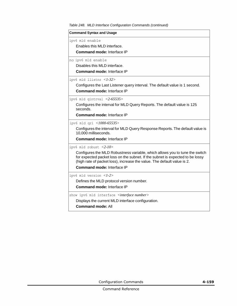
Configuration Commands 4-159
Command Reference
Table 248. MLD Interface Configuration Commands (continued)
Command Syntax and Usage
ipv6 mld enable
Enables this MLD interface.
Command mode: Interface IP
no ipv6 mld enable
Disables this MLD interface.
Command mode: Interface IP
ipv6 mld llistnr <1-32>
Configures the Last Listener query interval. The default value is 1 second.
Command mode: Interface IP
ipv6 mld qintrval <2-65535>
Configures the interval for MLD Query Reports. The default value is 125 seconds.
Command mode: Interface IP
ipv6 mld qri <1000-65535>
Configures the interval for MLD Query Response Reports. The default value is 10,000 milliseconds.
Command mode: Interface IP
ipv6 mld robust <2-10>
Configures the MLD Robustness variable, which allows you to tune the switch for expected packet loss on the subnet. If the subnet is expected to be lossy (high rate of packet loss), increase the value. The default value is 2.
Command mode: Interface IP
ipv6 mld version <1-2>
Defines the MLD protocol version number.
Command mode: Interface IP
show ipv6 mld interface <interface number>
Displays the current MLD interface configuration.
Command mode: All
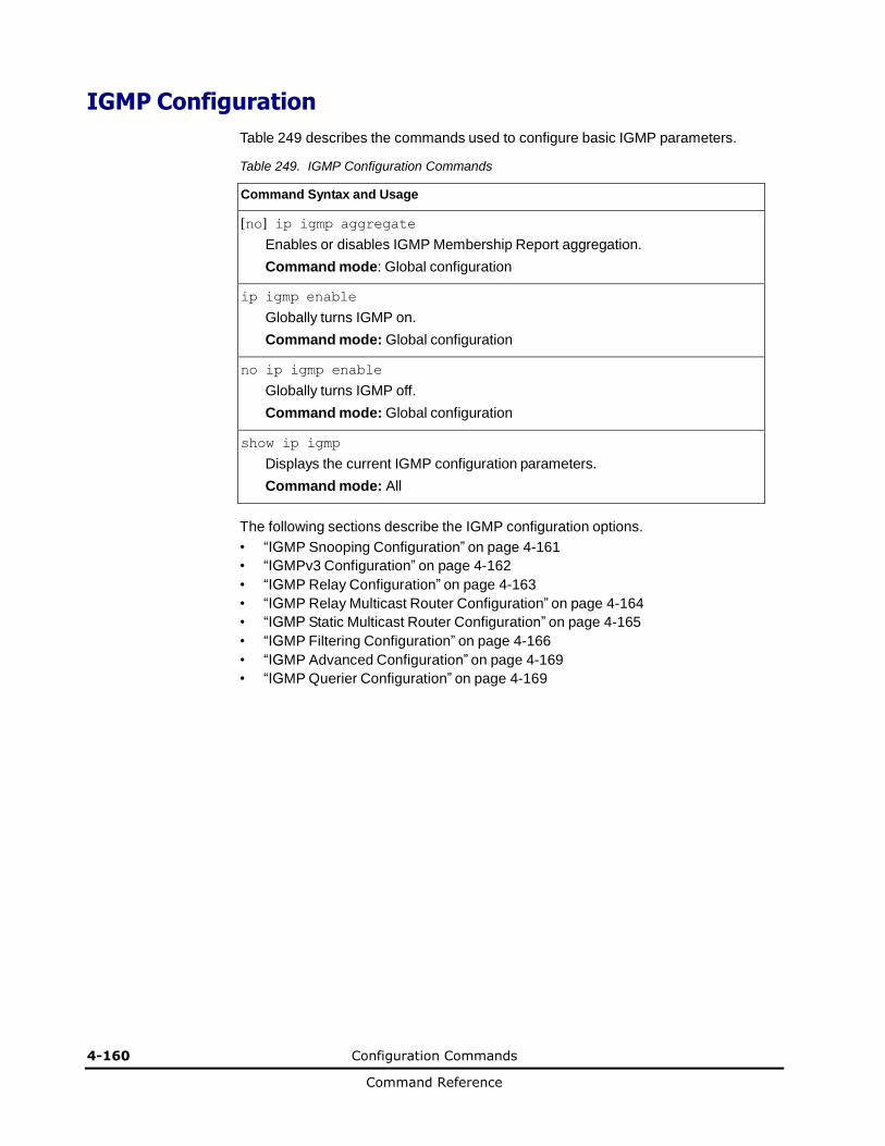
4-160 Configuration Commands
Command Reference
IGMP Configuration
Table 249 describes the commands used to configure basic IGMP parameters.
Table 249. IGMP Configuration Commands
Command Syntax and Usage
[no] ip igmp aggregate
Enables or disables IGMP Membership Report aggregation.
Command mode: Global configuration
ip igmp enable
Globally turns IGMP on.
Command mode: Global configuration
no ip igmp enable
Globally turns IGMP off.
Command mode: Global configuration
show ip igmp
Displays the current IGMP configuration parameters.
Command mode: All
The following sections describe the IGMP configuration options.
• “IGMP Snooping Configuration” on page 4-161
• “IGMPv3 Configuration” on page 4-162
• “IGMP Relay Configuration” on page 4-163
• “IGMP Relay Multicast Router Configuration” on page 4-164
• “IGMP Static Multicast Router Configuration” on page 4-165
• “IGMP Filtering Configuration” on page 4-166
• “IGMP Advanced Configuration” on page 4-169
• “IGMP Querier Configuration” on page 4-169
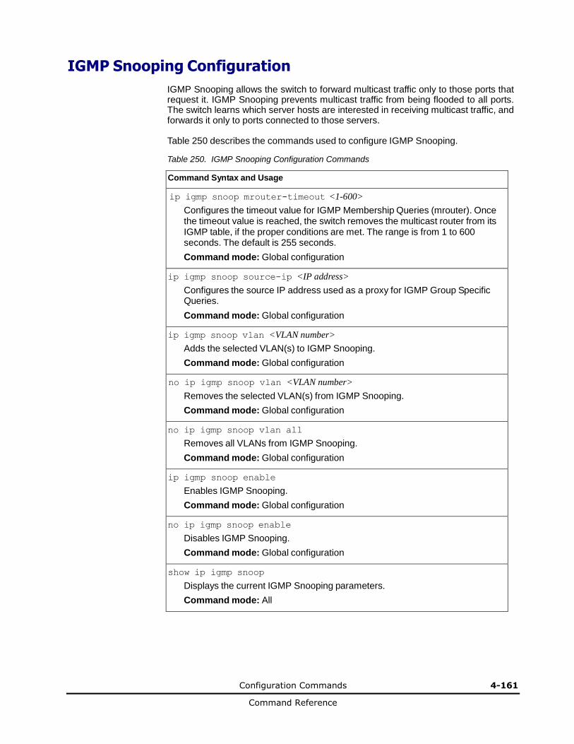
Configuration Commands 4-161
Command Reference
IGMP Snooping Configuration
IGMP Snooping allows the switch to forward multicast traffic only to those ports that request it. IGMP Snooping prevents multicast traffic from being flooded to all ports. The switch learns which server hosts are interested in receiving multicast traffic, and forwards it only to ports connected to those servers.
Table 250 describes the commands used to configure IGMP Snooping.
Table 250. IGMP Snooping Configuration Commands
Command Syntax and Usage
ip igmp snoop mrouter-timeout <1-600>
Configures the timeout value for IGMP Membership Queries (mrouter). Once the timeout value is reached, the switch removes the multicast router from its IGMP table, if the proper conditions are met. The range is from 1 to 600 seconds. The default is 255 seconds.
Command mode: Global configuration
ip igmp snoop source-ip <IP address>
Configures the source IP address used as a proxy for IGMP Group Specific Queries.
Command mode: Global configuration
ip igmp snoop vlan <VLAN number>
Adds the selected VLAN(s) to IGMP Snooping.
Command mode: Global configuration
no ip igmp snoop vlan <VLAN number>
Removes the selected VLAN(s) from IGMP Snooping.
Command mode: Global configuration
no ip igmp snoop vlan all
Removes all VLANs from IGMP Snooping.
Command mode: Global configuration
ip igmp snoop enable
Enables IGMP Snooping.
Command mode: Global configuration
no ip igmp snoop enable
Disables IGMP Snooping.
Command mode: Global configuration
show ip igmp snoop
Displays the current IGMP Snooping parameters.
Command mode: All

4-162 Configuration Commands
Command Reference
IGMPv3 Configuration
Table 251 describes the commands used to configure IGMP version 3.
Table 251. IGMP version 3 Configuration Commands
Command Syntax and Usage
ip igmp snoop igmpv3 sources <1-64>
Configures the maximum number of IGMP multicast sources to snoop from within the group record. Use this command to limit the number of IGMP sources to provide more refined control. The default value is 8.
Command mode: Global configuration
[no] ip igmp snoop igmpv3 v1v2
Enables or disables snooping on IGMP version 1 and version 2 reports. When disabled, the switch drops IGMPv1 and IGMPv2 reports. The default value is
enabled.
Command mode: Global configuration
[no] ip igmp snoop igmpv3 exclude
Enables or disables snooping on IGMPv3 Exclude Reports. When disabled, the switch ignores Exclude Reports. The default value is enabled.
Command mode: Global configuration
ip igmp snoop igmpv3 enable
Enables IGMP version 3. The default value is disabled.
Command mode: Global configuration
no ip igmp snoop igmpv3 enable
Disables IGMP version 3.
Command mode: Global configuration
show ip igmp snoop igmpv3
Displays the current IGMP v3 Snooping configuration.
Command mode: All
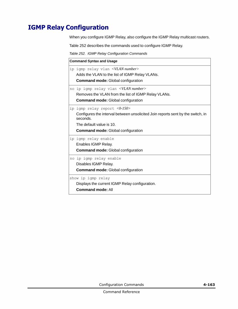
Configuration Commands 4-163
Command Reference
IGMP Relay Configuration
When you configure IGMP Relay, also configure the IGMP Relay multicast routers.
Table 252 describes the commands used to configure IGMP Relay.
Table 252. IGMP Relay Configuration Commands
Command Syntax and Usage
ip igmp relay vlan <VLAN number>
Adds the VLAN to the list of IGMP Relay VLANs.
Command mode: Global configuration
no ip igmp relay vlan <VLAN number>
Removes the VLAN from the list of IGMP Relay VLANs.
Command mode: Global configuration
ip igmp relay report <0-150>
Configures the interval between unsolicited Join reports sent by the switch, in seconds.
The default value is 10.
Command mode: Global configuration
ip igmp relay enable
Enables IGMP Relay.
Command mode: Global configuration
no ip igmp relay enable
Disables IGMP Relay.
Command mode: Global configuration
show ip igmp relay
Displays the current IGMP Relay configuration.
Command mode: All
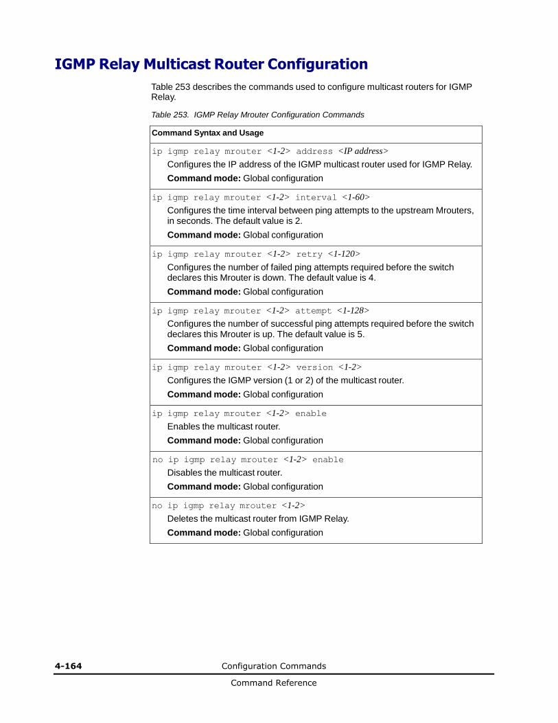
4-164 Configuration Commands
Command Reference
IGMP Relay Multicast Router Configuration
Table 253 describes the commands used to configure multicast routers for IGMP Relay.
Table 253. IGMP Relay Mrouter Configuration Commands
Command Syntax and Usage
ip igmp relay mrouter <1-2> address <IP address>
Configures the IP address of the IGMP multicast router used for IGMP Relay.
Command mode: Global configuration
ip igmp relay mrouter <1-2> interval <1-60>
Configures the time interval between ping attempts to the upstream Mrouters, in seconds. The default value is 2.
Command mode: Global configuration
ip igmp relay mrouter <1-2> retry <1-120>
Configures the number of failed ping attempts required before the switch declares this Mrouter is down. The default value is 4.
Command mode: Global configuration
ip igmp relay mrouter <1-2> attempt <1-128>
Configures the number of successful ping attempts required before the switch declares this Mrouter is up. The default value is 5.
Command mode: Global configuration
ip igmp relay mrouter <1-2> version <1-2>
Configures the IGMP version (1 or 2) of the multicast router.
Command mode: Global configuration
ip igmp relay mrouter <1-2> enable
Enables the multicast router.
Command mode: Global configuration
no ip igmp relay mrouter <1-2> enable
Disables the multicast router.
Command mode: Global configuration
no ip igmp relay mrouter <1-2>
Deletes the multicast router from IGMP Relay.
Command mode: Global configuration
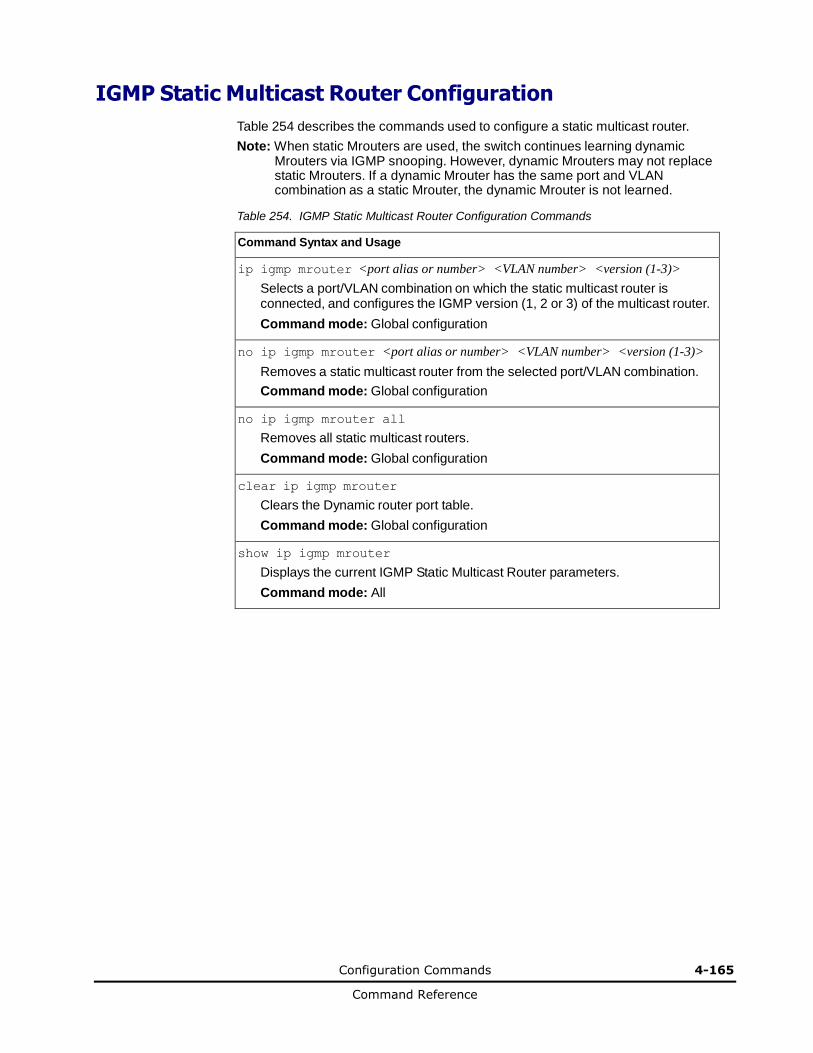
Configuration Commands 4-165
Command Reference
IGMP Static Multicast Router Configuration
Table 254 describes the commands used to configure a static multicast router.
Note: When static Mrouters are used, the switch continues learning dynamic Mrouters via IGMP snooping. However, dynamic Mrouters may not replace static Mrouters. If a dynamic Mrouter has the same port and VLAN combination as a static Mrouter, the dynamic Mrouter is not learned.
Table 254. IGMP Static Multicast Router Configuration Commands
Command Syntax and Usage
ip igmp mrouter <port alias or number> <VLAN number> <version (1-3)>
Selects a port/VLAN combination on which the static multicast router is connected, and configures the IGMP version (1, 2 or 3) of the multicast router.
Command mode: Global configuration
no ip igmp mrouter <port alias or number> <VLAN number> <version (1-3)>
Removes a static multicast router from the selected port/VLAN combination.
Command mode: Global configuration
no ip igmp mrouter all
Removes all static multicast routers.
Command mode: Global configuration
clear ip igmp mrouter
Clears the Dynamic router port table.
Command mode: Global configuration
show ip igmp mrouter
Displays the current IGMP Static Multicast Router parameters.
Command mode: All

4-166 Configuration Commands
Command Reference
IGMP Filtering Configuration
Table 255 describes the commands used to configure an IGMP filter.
Table 255. IGMP Filtering Configuration Commands
Command Syntax and Usage
ip igmp profile <1-16>
Configures the IGMP filter. To view command options, see page 4-167.
Command mode: Global configuration
ip igmp filtering
Enables IGMP filtering globally.
Command mode: Global configuration
no ip igmp filtering
Disables IGMP filtering globally.
Command mode: Global configuration
show ip igmp filtering
Displays the current IGMP Filtering parameters.
Command mode: All

Configuration Commands 4-167
Command Reference
IGMP Filter Definition
Table 256 describes the commands used to define an IGMP filter.
Table 256. IGMP Filter Definition Commands
Command Syntax and Usage
ip igmp profile <1-16> range <IP address 1> <IP address 2>
Configures the range of IP multicast addresses for this filter.
Command mode: Global configuration
ip igmp profile <1-16> action {allow|deny}
Allows or denies multicast traffic for the IP multicast addresses specified. The
default action is deny.
Command mode: Global configuration
ip igmp profile <1-16> enable
Enables this IGMP filter.
Command mode: Global configuration
no ip igmp profile <1-16> enable
Disables this IGMP filter.
Command mode: Global configuration
no ip igmp profile <1-16>
Deletes this filter’s parameter definitions.
Command mode: Global configuration
show ip igmp profile <1-16>
Displays the current IGMP filter.
Command mode: All
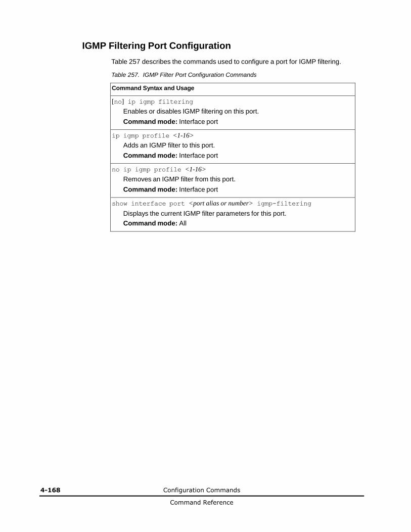
4-168 Configuration Commands
Command Reference
IGMP Filtering Port Configuration
Table 257 describes the commands used to configure a port for IGMP filtering.
Table 257. IGMP Filter Port Configuration Commands
Command Syntax and Usage
[no] ip igmp filtering
Enables or disables IGMP filtering on this port.
Command mode: Interface port
ip igmp profile <1-16>
Adds an IGMP filter to this port.
Command mode: Interface port
no ip igmp profile <1-16>
Removes an IGMP filter from this port.
Command mode: Interface port
show interface port <port alias or number> igmp-filtering
Displays the current IGMP filter parameters for this port.
Command mode: All
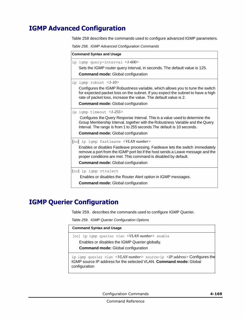
Configuration Commands 4-169
Command Reference
IGMP Advanced Configuration
Table 258 describes the commands used to configure advanced IGMP parameters.
Table 258. IGMP Advanced Configuration Commands
Command Syntax and Usage
ip igmp query-interval <1-600>
Sets the IGMP router query interval, in seconds. The default value is 125.
Command mode: Global configuration
ip igmp robust <1-10>
Configures the IGMP Robustness variable, which allows you to tune the switch for expected packet loss on the subnet. If you expect the subnet to have a high rate of packet loss, increase the value. The default value is 2.
Command mode: Global configuration
ip igmp timeout <1-255>
Configures the Query Response Interval. This is a value used to determine the Group Membership Interval, together with the Robustness Variable and the Query Interval. The range is from 1 to 255 seconds.The default is 10 seconds.
Command mode: Global configuration
[no] ip igmp fastleave <VLAN number>
Enables or disables Fastleave processing. Fastleave lets the switch immediately remove a port from the IGMP port list if the host sends a Leave message and the proper conditions are met. This command is disabled by default.
Command mode: Global configuration
[no] ip igmp rtralert
Enables or disables the Router Alert option in IGMP messages.
Command mode: Global configuration
IGMP Querier Configuration
Table 259. describes the commands used to configure IGMP Querier.
Table 259. IGMP Querier Configuration Options
Command Syntax and Usage
[no] ip igmp querier vlan <VLAN number> enable
Enables or disables the IGMP Querier globally.
Command mode: Global configuration
ip igmp querier vlan <VLAN number> source-ip <IP address> Configures the
IGMP source IP address for the selected VLAN. Command mode: Global configuration
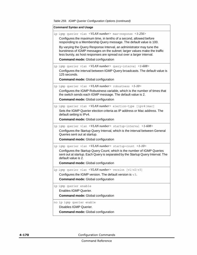
4-170 Configuration Commands
Command Reference
Table 259. IGMP Querier Configuration Options (continued)
Command Syntax and Usage
ip igmp querier vlan <VLAN number> max-response <1-256>
Configures the maximum time, in tenths of a second, allowed before responding to a Membership Query message. The default value is 100.
By varying the Query Response Interval, an administrator may tune the burstiness of IGMP messages on the subnet; larger values make the traffic less bursty, as host responses are spread out over a larger interval.
Command mode: Global configuration
ip igmp querier vlan <VLAN number> query-interval <1-608>
Configures the interval between IGMP Query broadcasts. The default value is 125 seconds.
Command mode: Global configuration
ip igmp querier vlan <VLAN number> robustness <1-10>
Configures the IGMP Robustness variable, which is the number of times that the switch sends each IGMP message. The default value is 2.
Command mode: Global configuration
ip igmp querier vlan <VLAN number> election-type [ipv4|mac]
Sets the IGMP Querier election criteria as IP address or Mac address. The default setting is IPv4.
Command mode: Global configuration
ip igmp querier vlan <VLAN number> startup-interval <1-608>
Configures the Startup Query Interval, which is the interval between General Queries sent out at startup.
Command mode: Global configuration
ip igmp querier vlan <VLAN number> startup-count <1-10>
Configures the Startup Query Count, which is the number of IGMP Queries sent out at startup. Each Query is separated by the Startup Query Interval. The default value is 2.
Command mode: Global configuration
ip igmp querier vlan <VLAN number> version [v1|v2|v3]
Configures the IGMP version. The default version is v3.
Command mode: Global configuration
ip igmp querier enable
Enables IGMP Querier.
Command mode: Global configuration
no ip igmp querier enable
Disables IGMP Querier.
Command mode: Global configuration
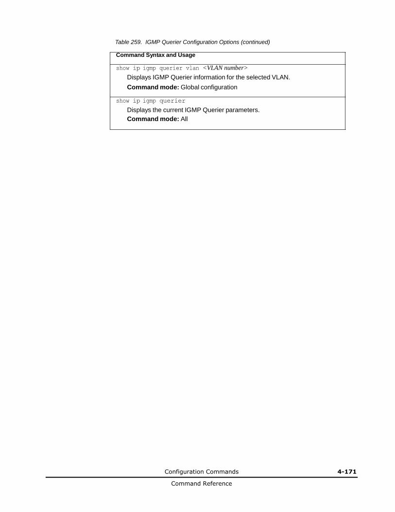
Configuration Commands 4-171
Command Reference
Table 259. IGMP Querier Configuration Options (continued)
Command Syntax and Usage
show ip igmp querier vlan <VLAN number>
Displays IGMP Querier information for the selected VLAN.
Command mode: Global configuration
show ip igmp querier
Displays the current IGMP Querier parameters.
Command mode: All
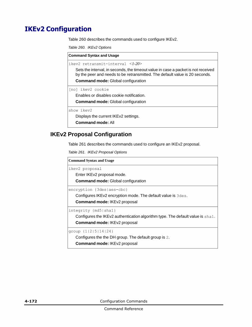
4-172 Configuration Commands
Command Reference
IKEv2 Configuration
Table 260 describes the commands used to configure IKEv2.
Table 260. IKEv2 Options
Command Syntax and Usage
ikev2 retransmit-interval <1-20>
Sets the interval, in seconds, the timeout value in case a packet is not received by the peer and needs to be retransmitted. The default value is 20 seconds.
Command mode: Global configuration
[no] ikev2 cookie
Enables or disables cookie notification.
Command mode: Global configuration
show ikev2
Displays the current IKEv2 settings.
Command mode: All
IKEv2 Proposal Configuration
Table 261 describes the commands used to configure an IKEv2 proposal.
Table 261. IKEv2 Proposal Options
Command Syntax and Usage
ikev2 proposal
Enter IKEv2 proposal mode.
Command mode: Global configuration
encryption {3des|aes-cbc}
Configures IKEv2 encryption mode. The default value is 3des.
Command mode: IKEv2 proposal
integrity {md5|sha1}
Configures the IKEv2 authentication algorithm type. The default value is sha1.
Command mode: IKEv2 proposal
group {1|2|5|14|24}
Configures the the DH group. The default group is 2.
Command mode: IKEv2 proposal
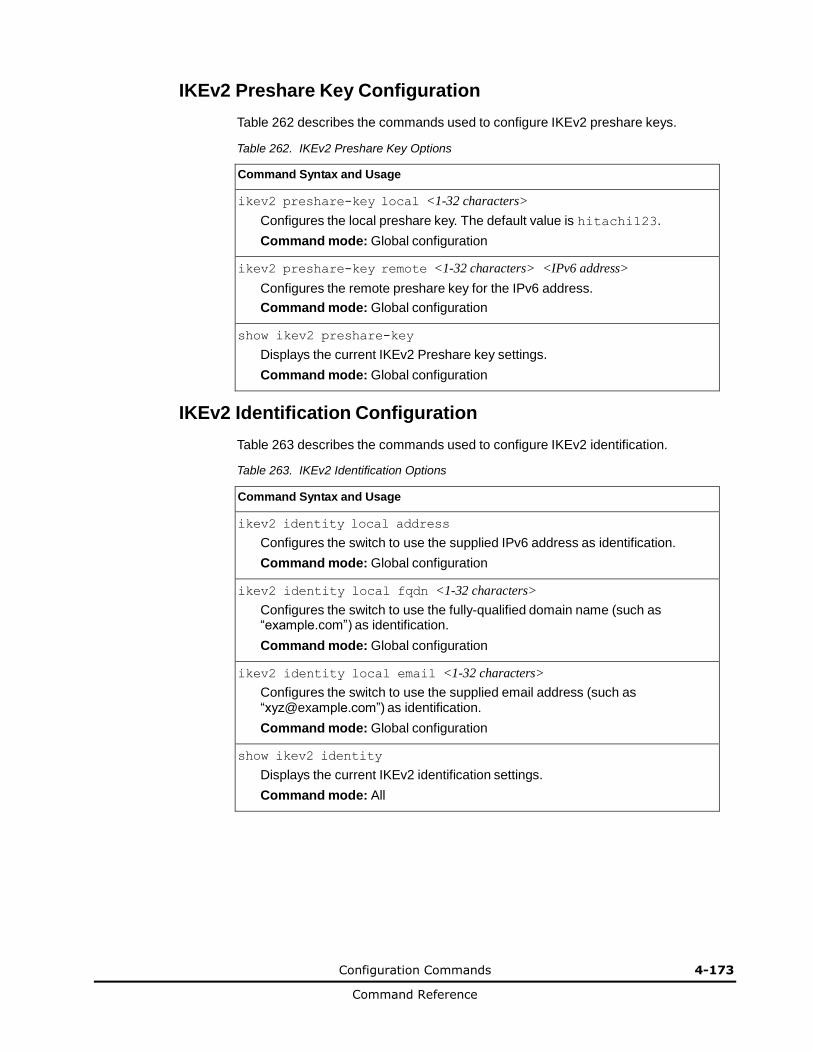
Configuration Commands 4-173
Command Reference
IKEv2 Preshare Key Configuration
Table 262 describes the commands used to configure IKEv2 preshare keys.
Table 262. IKEv2 Preshare Key Options
Command Syntax and Usage
ikev2 preshare-key local <1-32 characters>
Configures the local preshare key. The default value is hitachi123.
Command mode: Global configuration
ikev2 preshare-key remote <1-32 characters> <IPv6 address>
Configures the remote preshare key for the IPv6 address.
Command mode: Global configuration
show ikev2 preshare-key
Displays the current IKEv2 Preshare key settings.
Command mode: Global configuration
IKEv2 Identification Configuration
Table 263 describes the commands used to configure IKEv2 identification.
Table 263. IKEv2 Identification Options
Command Syntax and Usage
ikev2 identity local address
Configures the switch to use the supplied IPv6 address as identification.
Command mode: Global configuration
ikev2 identity local fqdn <1-32 characters>
Configures the switch to use the fully-qualified domain name (such as “example.com”) as identification.
Command mode: Global configuration
ikev2 identity local email <1-32 characters>
Configures the switch to use the supplied email address (such as “[email protected]”) as identification.
Command mode: Global configuration
show ikev2 identity
Displays the current IKEv2 identification settings.
Command mode: All
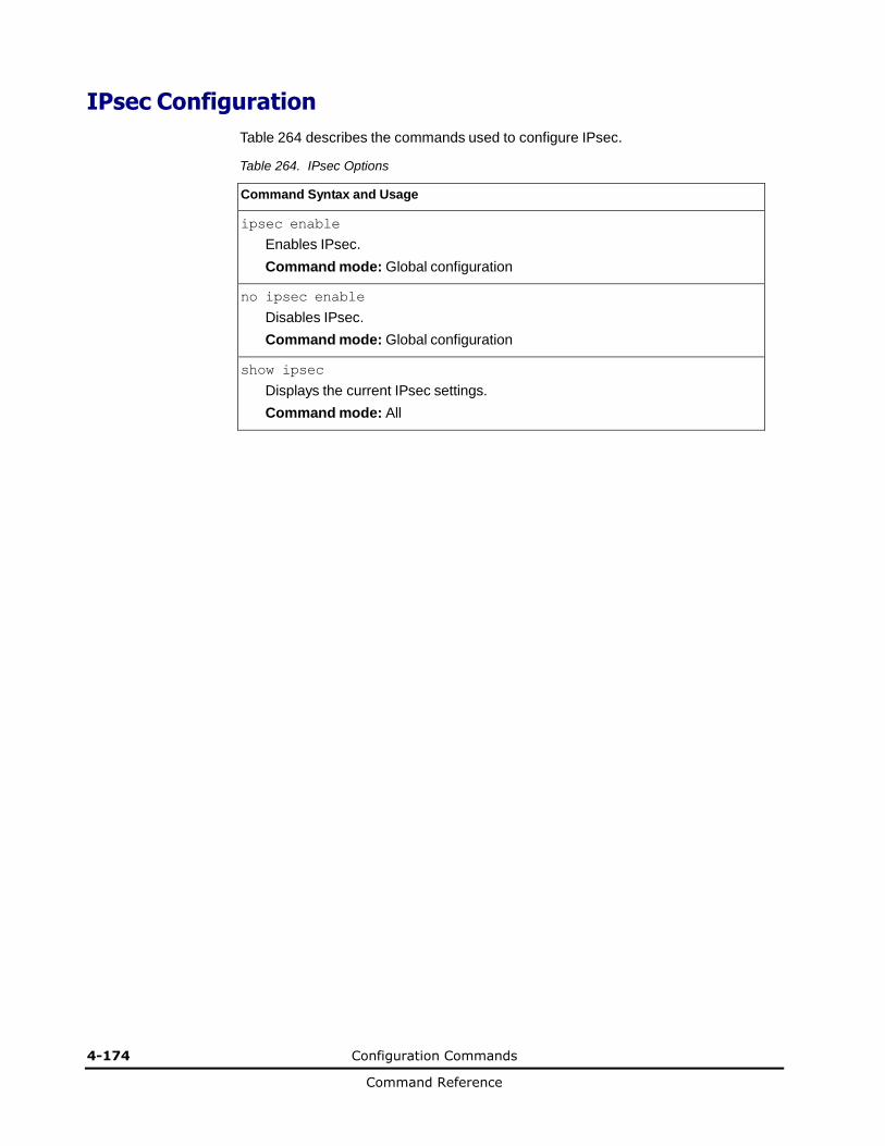
4-174 Configuration Commands
Command Reference
IPsec Configuration
Table 264 describes the commands used to configure IPsec.
Table 264. IPsec Options
Command Syntax and Usage
ipsec enable
Enables IPsec.
Command mode: Global configuration
no ipsec enable
Disables IPsec.
Command mode: Global configuration
show ipsec
Displays the current IPsec settings.
Command mode: All
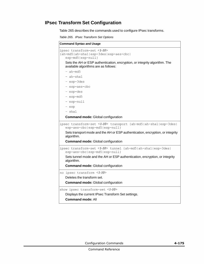
Configuration Commands 4-175
Command Reference
IPsec Transform Set Configuration
Table 265 describes the commands used to configure IPsec transforms.
Table 265. IPsec Transform Set Options
Command Syntax and Usage
ipsec transform-set <1-10> {ah-md5|ah-sha1|esp-3des|esp-aes-cbc|
esp-md5|esp-null}
Sets the AH or ESP authentication, encryption, or integrity algorithm. The available algorithms are as follows:
– ah-md5
– ah-sha1
– esp-3des
– esp-aes-cbc
– esp-des
– esp-md5
– esp-null
– esp
– sha1
Command mode: Global configuration
ipsec transform-set <1-10> transport {ah-md5|ah-sha1|esp-3des| esp-aes-cbc|esp-md5|esp-null}
Sets transport mode and the AH or ESP authentication, encryption, or integrity algorithm.
Command mode: Global configuration
ipsec transform-set <1-10> tunnel {ah-md5|ah-sha1|esp-3des| esp-aes-cbc|esp-md5|esp-null}
Sets tunnel mode and the AH or ESP authentication, encryption, or integrity algorithm.
Command mode: Global configuration
no ipsec transform <1-10>
Deletes the transform set.
Command mode: Global configuration
show ipsec transform-set <1-10>
Displays the current IPsec Transform Set settings.
Command mode: All
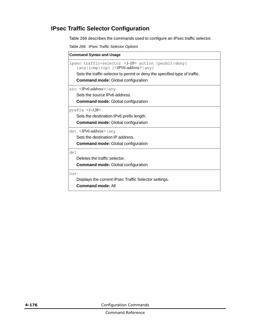
4-176 Configuration Commands
Command Reference
IPsec Traffic Selector Configuration
Table 266 describes the commands used to configure an IPsec traffic selector.
Table 266. IPsec Traffic Selector Options
Command Syntax and Usage
ipsec traffic-selector <1-10> action {permit|deny} {any|icmp|tcp} {<IPV6 address>|any}
Sets the traffic-selector to permit or deny the specified type of traffic.
Command mode: Global configuration
src <IPv6 address>|any
Sets the source IPv6 address.
Command mode: Global configuration
prefix <1-128>
Sets the destination IPv6 prefix length.
Command mode: Global configuration
dst <IPv6 address>|any
Sets the destination IP address.
Command mode: Global configuration
del
Deletes the traffic selector.
Command mode: Global configuration
cur
Displays the current IPsec Traffic Selector settings.
Command mode: All
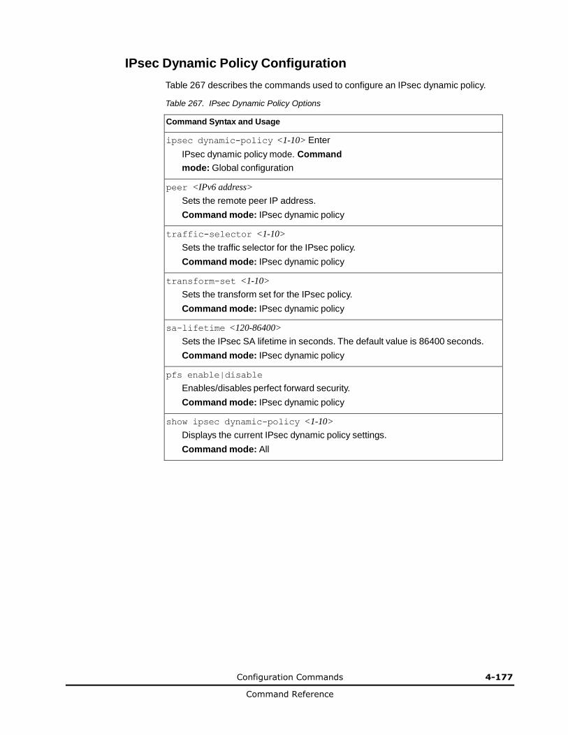
Configuration Commands 4-177
Command Reference
IPsec Dynamic Policy Configuration
Table 267 describes the commands used to configure an IPsec dynamic policy.
Table 267. IPsec Dynamic Policy Options
Command Syntax and Usage
ipsec dynamic-policy <1-10> Enter
IPsec dynamic policy mode. Command
mode: Global configuration
peer <IPv6 address>
Sets the remote peer IP address.
Command mode: IPsec dynamic policy
traffic-selector <1-10>
Sets the traffic selector for the IPsec policy.
Command mode: IPsec dynamic policy
transform-set <1-10>
Sets the transform set for the IPsec policy.
Command mode: IPsec dynamic policy
sa-lifetime <120-86400>
Sets the IPsec SA lifetime in seconds. The default value is 86400 seconds.
Command mode: IPsec dynamic policy
pfs enable|disable
Enables/disables perfect forward security.
Command mode: IPsec dynamic policy
show ipsec dynamic-policy <1-10>
Displays the current IPsec dynamic policy settings.
Command mode: All
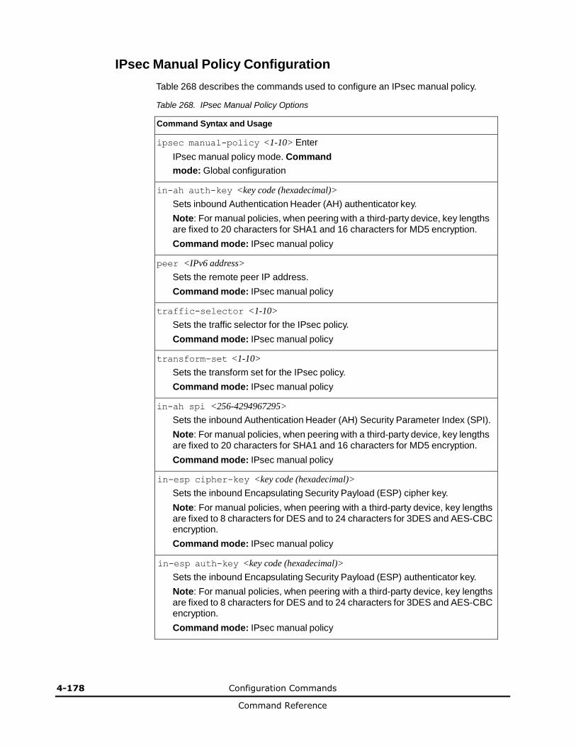
4-178 Configuration Commands
Command Reference
IPsec Manual Policy Configuration
Table 268 describes the commands used to configure an IPsec manual policy.
Table 268. IPsec Manual Policy Options
Command Syntax and Usage
ipsec manual-policy <1-10> Enter
IPsec manual policy mode. Command
mode: Global configuration
in-ah auth-key <key code (hexadecimal)>
Sets inbound Authentication Header (AH) authenticator key.
Note: For manual policies, when peering with a third-party device, key lengths are fixed to 20 characters for SHA1 and 16 characters for MD5 encryption.
Command mode: IPsec manual policy
peer <IPv6 address>
Sets the remote peer IP address.
Command mode: IPsec manual policy
traffic-selector <1-10>
Sets the traffic selector for the IPsec policy.
Command mode: IPsec manual policy
transform-set <1-10>
Sets the transform set for the IPsec policy.
Command mode: IPsec manual policy
in-ah spi <256-4294967295>
Sets the inbound Authentication Header (AH) Security Parameter Index (SPI).
Note: For manual policies, when peering with a third-party device, key lengths are fixed to 20 characters for SHA1 and 16 characters for MD5 encryption.
Command mode: IPsec manual policy
in-esp cipher-key <key code (hexadecimal)>
Sets the inbound Encapsulating Security Payload (ESP) cipher key.
Note: For manual policies, when peering with a third-party device, key lengths are fixed to 8 characters for DES and to 24 characters for 3DES and AES-CBC encryption.
Command mode: IPsec manual policy
in-esp auth-key <key code (hexadecimal)>
Sets the inbound Encapsulating Security Payload (ESP) authenticator key.
Note: For manual policies, when peering with a third-party device, key lengths are fixed to 8 characters for DES and to 24 characters for 3DES and AES-CBC encryption.
Command mode: IPsec manual policy
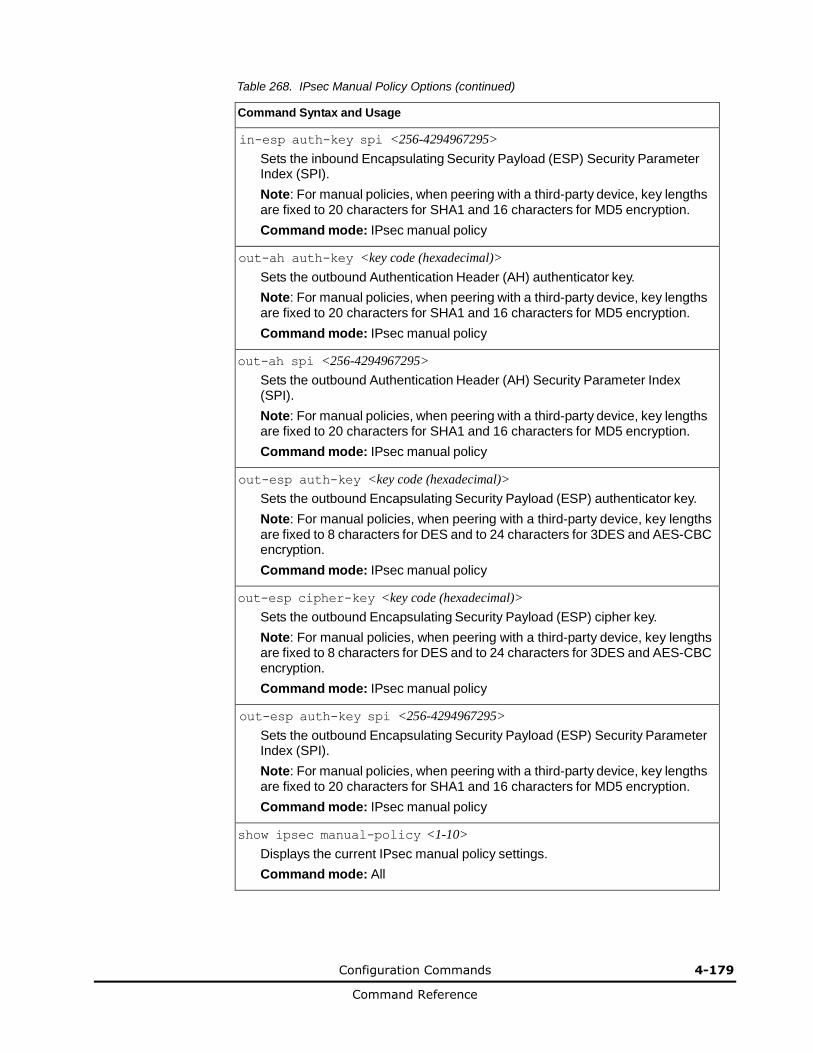
Configuration Commands 4-179
Command Reference
Table 268. IPsec Manual Policy Options (continued)
Command Syntax and Usage
in-esp auth-key spi <256-4294967295>
Sets the inbound Encapsulating Security Payload (ESP) Security Parameter Index (SPI).
Note: For manual policies, when peering with a third-party device, key lengths are fixed to 20 characters for SHA1 and 16 characters for MD5 encryption.
Command mode: IPsec manual policy
out-ah auth-key <key code (hexadecimal)>
Sets the outbound Authentication Header (AH) authenticator key.
Note: For manual policies, when peering with a third-party device, key lengths are fixed to 20 characters for SHA1 and 16 characters for MD5 encryption.
Command mode: IPsec manual policy
out-ah spi <256-4294967295>
Sets the outbound Authentication Header (AH) Security Parameter Index (SPI).
Note: For manual policies, when peering with a third-party device, key lengths are fixed to 20 characters for SHA1 and 16 characters for MD5 encryption.
Command mode: IPsec manual policy
out-esp auth-key <key code (hexadecimal)>
Sets the outbound Encapsulating Security Payload (ESP) authenticator key.
Note: For manual policies, when peering with a third-party device, key lengths are fixed to 8 characters for DES and to 24 characters for 3DES and AES-CBC encryption.
Command mode: IPsec manual policy
out-esp cipher-key <key code (hexadecimal)>
Sets the outbound Encapsulating Security Payload (ESP) cipher key.
Note: For manual policies, when peering with a third-party device, key lengths are fixed to 8 characters for DES and to 24 characters for 3DES and AES-CBC encryption.
Command mode: IPsec manual policy
out-esp auth-key spi <256-4294967295>
Sets the outbound Encapsulating Security Payload (ESP) Security Parameter Index (SPI).
Note: For manual policies, when peering with a third-party device, key lengths are fixed to 20 characters for SHA1 and 16 characters for MD5 encryption.
Command mode: IPsec manual policy
show ipsec manual-policy <1-10>
Displays the current IPsec manual policy settings.
Command mode: All
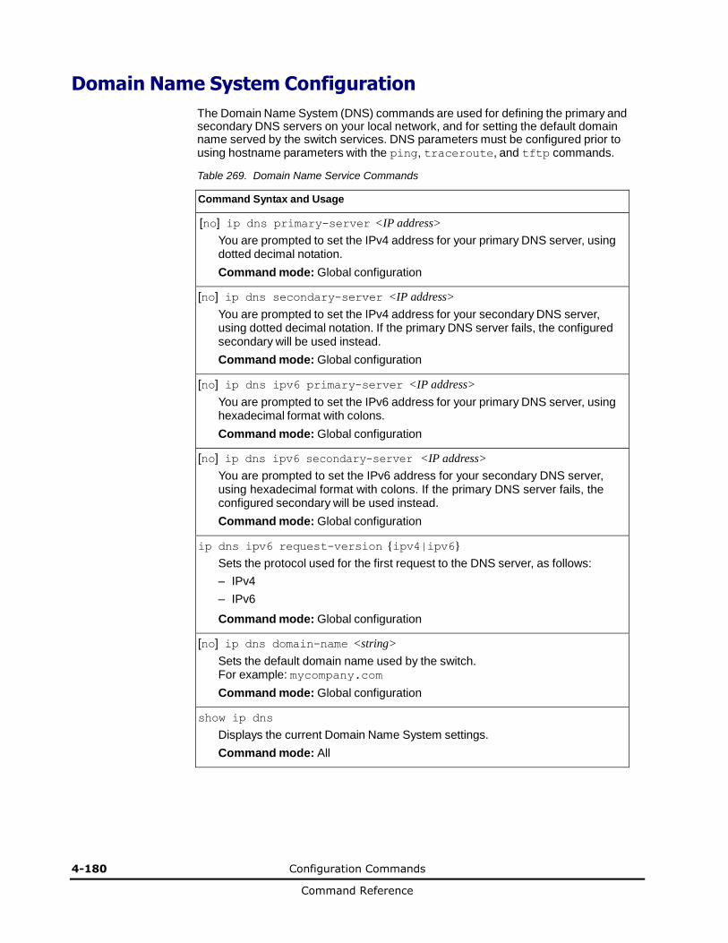
4-180 Configuration Commands
Command Reference
Domain Name System Configuration
The Domain Name System (DNS) commands are used for defining the primary and secondary DNS servers on your local network, and for setting the default domain name served by the switch services. DNS parameters must be configured prior to using hostname parameters with the ping, traceroute, and tftp commands.
Table 269. Domain Name Service Commands
Command Syntax and Usage
[no] ip dns primary-server <IP address>
You are prompted to set the IPv4 address for your primary DNS server, using dotted decimal notation.
Command mode: Global configuration
[no] ip dns secondary-server <IP address>
You are prompted to set the IPv4 address for your secondary DNS server, using dotted decimal notation. If the primary DNS server fails, the configured secondary will be used instead.
Command mode: Global configuration
[no] ip dns ipv6 primary-server <IP address>
You are prompted to set the IPv6 address for your primary DNS server, using hexadecimal format with colons.
Command mode: Global configuration
[no] ip dns ipv6 secondary-server <IP address>
You are prompted to set the IPv6 address for your secondary DNS server, using hexadecimal format with colons. If the primary DNS server fails, the configured secondary will be used instead.
Command mode: Global configuration
ip dns ipv6 request-version {ipv4|ipv6}
Sets the protocol used for the first request to the DNS server, as follows:
– IPv4
– IPv6
Command mode: Global configuration
[no] ip dns domain-name <string>
Sets the default domain name used by the switch. For example: mycompany.com
Command mode: Global configuration
show ip dns
Displays the current Domain Name System settings.
Command mode: All
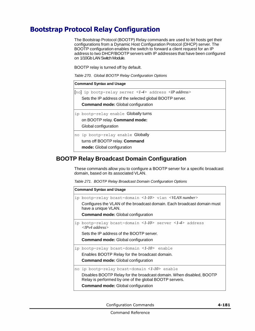
Configuration Commands 4-181
Command Reference
Bootstrap Protocol Relay Configuration
The Bootstrap Protocol (BOOTP) Relay commands are used to let hosts get their configurations from a Dynamic Host Configuration Protocol (DHCP) server. The BOOTP configuration enables the switch to forward a client request for an IP address to two DHCP/BOOTP servers with IP addresses that have been configured on 1/10Gb LAN Switch Module.
BOOTP relay is turned off by default.
Table 270. Global BOOTP Relay Configuration Options
Command Syntax and Usage
[no] ip bootp-relay server <1-4> address <IP address>
Sets the IP address of the selected global BOOTP server.
Command mode: Global configuration
ip bootp-relay enable Globally turns
on BOOTP relay. Command mode:
Global configuration
no ip bootp-relay enable Globally
turns off BOOTP relay. Command
mode: Global configuration
BOOTP Relay Broadcast Domain Configuration
These commands allow you to configure a BOOTP server for a specific broadcast domain, based on its associated VLAN.
Table 271. BOOTP Relay Broadcast Domain Configuration Options
Command Syntax and Usage
ip bootp-relay bcast-domain <1-10> vlan <VLAN number>
Configures the VLAN of the broadcast domain. Each broadcast domain must have a unique VLAN.
Command mode: Global configuration
ip bootp-relay bcast-domain <1-10> server <1-4> address <IPv4 address>
Sets the IP address of the BOOTP server.
Command mode: Global configuration
ip bootp-relay bcast-domain <1-10> enable
Enables BOOTP Relay for the broadcast domain.
Command mode: Global configuration
no ip bootp-relay bcast-domain <1-10> enable
Disables BOOTP Relay for the broadcast domain. When disabled, BOOTP Relay is performed by one of the global BOOTP servers.
Command mode: Global configuration
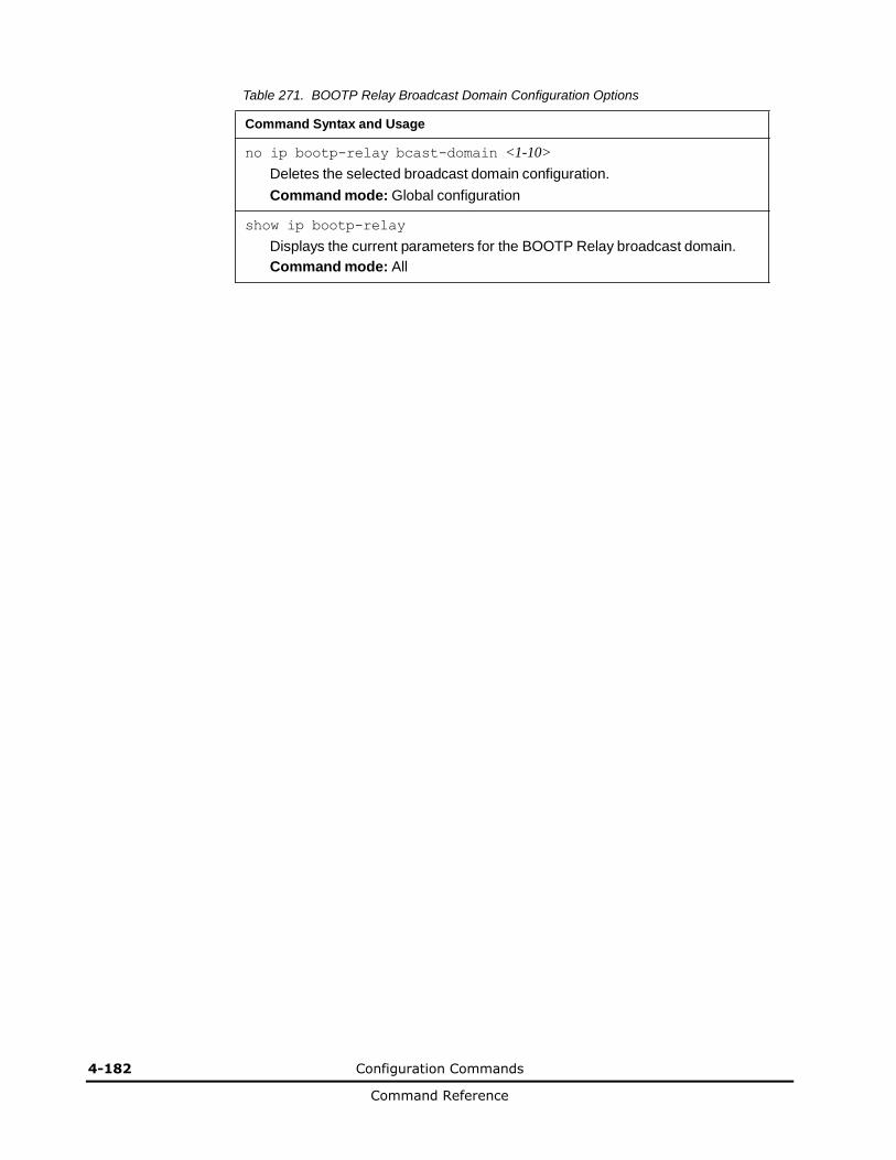
4-182 Configuration Commands
Command Reference
Table 271. BOOTP Relay Broadcast Domain Configuration Options
Command Syntax and Usage
no ip bootp-relay bcast-domain <1-10>
Deletes the selected broadcast domain configuration.
Command mode: Global configuration
show ip bootp-relay
Displays the current parameters for the BOOTP Relay broadcast domain.
Command mode: All
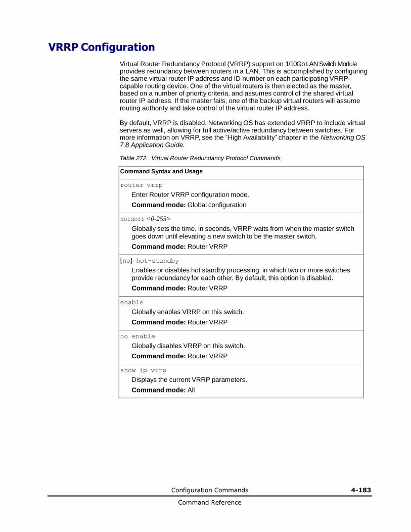
Configuration Commands 4-183
Command Reference
VRRP Configuration
Virtual Router Redundancy Protocol (VRRP) support on 1/10Gb LAN Switch Module provides redundancy between routers in a LAN. This is accomplished by configuring the same virtual router IP address and ID number on each participating VRRP-capable routing device. One of the virtual routers is then elected as the master, based on a number of priority criteria, and assumes control of the shared virtual router IP address. If the master fails, one of the backup virtual routers will assume routing authority and take control of the virtual router IP address.
By default, VRRP is disabled. Networking OS has extended VRRP to include virtual servers as well, allowing for full active/active redundancy between switches. For more information on VRRP, see the “High Availability” chapter in the Networking OS 7.8 Application Guide.
Table 272. Virtual Router Redundancy Protocol Commands
Command Syntax and Usage
router vrrp
Enter Router VRRP configuration mode.
Command mode: Global configuration
holdoff <0-255>
Globally sets the time, in seconds, VRRP waits from when the master switch goes down until elevating a new switch to be the master switch.
Command mode: Router VRRP
[no] hot-standby
Enables or disables hot standby processing, in which two or more switches provide redundancy for each other. By default, this option is disabled.
Command mode: Router VRRP
enable
Globally enables VRRP on this switch.
Command mode: Router VRRP
no enable
Globally disables VRRP on this switch.
Command mode: Router VRRP
show ip vrrp
Displays the current VRRP parameters.
Command mode: All
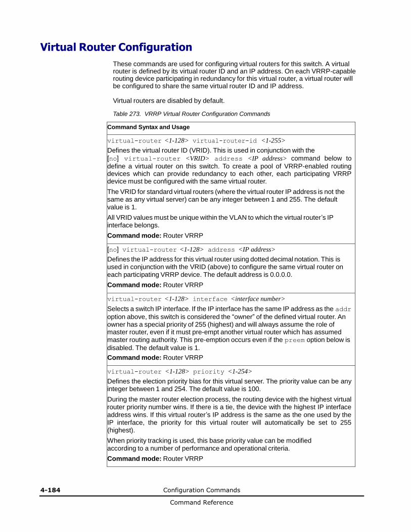
4-184 Configuration Commands
Command Reference
Virtual Router Configuration
These commands are used for configuring virtual routers for this switch. A virtual router is defined by its virtual router ID and an IP address. On each VRRP-capable routing device participating in redundancy for this virtual router, a virtual router will be configured to share the same virtual router ID and IP address.
Virtual routers are disabled by default.
Table 273. VRRP Virtual Router Configuration Commands
Command Syntax and Usage
virtual-router <1-128> virtual-router-id <1-255>
Defines the virtual router ID (VRID). This is used in conjunction with the
[no] virtual-router <VRID> address <IP address> command below to
define a virtual router on this switch. To create a pool of VRRP-enabled routing devices which can provide redundancy to each other, each participating VRRP device must be configured with the same virtual router.
The VRID for standard virtual routers (where the virtual router IP address is not the same as any virtual server) can be any integer between 1 and 255. The default value is 1.
All VRID values must be unique within the VLAN to which the virtual router’s IP interface belongs.
Command mode: Router VRRP
[no] virtual-router <1-128> address <IP address>
Defines the IP address for this virtual router using dotted decimal notation. This is used in conjunction with the VRID (above) to configure the same virtual router on each participating VRRP device. The default address is 0.0.0.0.
Command mode: Router VRRP
virtual-router <1-128> interface <interface number>
Selects a switch IP interface. If the IP interface has the same IP address as the addr
option above, this switch is considered the “owner” of the defined virtual router. An owner has a special priority of 255 (highest) and will always assume the role of master router, even if it must pre-empt another virtual router which has assumed master routing authority. This pre-emption occurs even if the preem option below is
disabled. The default value is 1.
Command mode: Router VRRP
virtual-router <1-128> priority <1-254>
Defines the election priority bias for this virtual server. The priority value can be any integer between 1 and 254. The default value is 100.
During the master router election process, the routing device with the highest virtual router priority number wins. If there is a tie, the device with the highest IP interface address wins. If this virtual router’s IP address is the same as the one used by the IP interface, the priority for this virtual router will automatically be set to 255 (highest).
When priority tracking is used, this base priority value can be modified according to a number of performance and operational criteria.
Command mode: Router VRRP
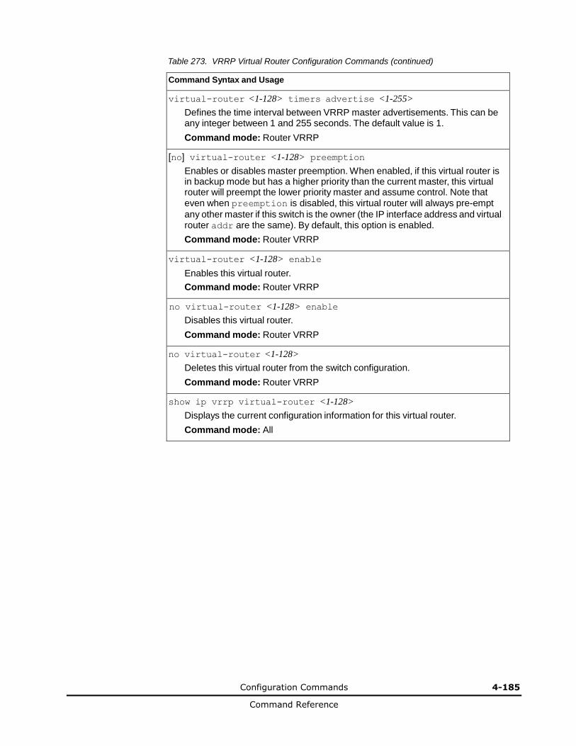
Configuration Commands 4-185
Command Reference
Table 273. VRRP Virtual Router Configuration Commands (continued)
Command Syntax and Usage
virtual-router <1-128> timers advertise <1-255>
Defines the time interval between VRRP master advertisements. This can be any integer between 1 and 255 seconds. The default value is 1.
Command mode: Router VRRP
[no] virtual-router <1-128> preemption
Enables or disables master preemption. When enabled, if this virtual router is in backup mode but has a higher priority than the current master, this virtual router will preempt the lower priority master and assume control. Note that even when preemption is disabled, this virtual router will always pre-empt
any other master if this switch is the owner (the IP interface address and virtual router addr are the same). By default, this option is enabled.
Command mode: Router VRRP
virtual-router <1-128> enable
Enables this virtual router.
Command mode: Router VRRP
no virtual-router <1-128> enable
Disables this virtual router.
Command mode: Router VRRP
no virtual-router <1-128>
Deletes this virtual router from the switch configuration.
Command mode: Router VRRP
show ip vrrp virtual-router <1-128>
Displays the current configuration information for this virtual router.
Command mode: All
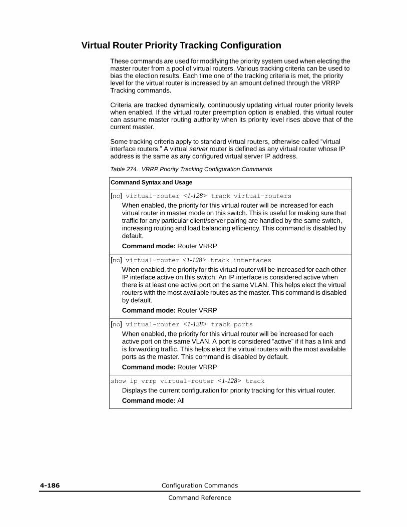
4-186 Configuration Commands
Command Reference
Virtual Router Priority Tracking Configuration
These commands are used for modifying the priority system used when electing the master router from a pool of virtual routers. Various tracking criteria can be used to bias the election results. Each time one of the tracking criteria is met, the priority level for the virtual router is increased by an amount defined through the VRRP Tracking commands.
Criteria are tracked dynamically, continuously updating virtual router priority levels when enabled. If the virtual router preemption option is enabled, this virtual router can assume master routing authority when its priority level rises above that of the current master.
Some tracking criteria apply to standard virtual routers, otherwise called “virtual interface routers.” A virtual server router is defined as any virtual router whose IP address is the same as any configured virtual server IP address.
Table 274. VRRP Priority Tracking Configuration Commands
Command Syntax and Usage
[no] virtual-router <1-128> track virtual-routers
When enabled, the priority for this virtual router will be increased for each virtual router in master mode on this switch. This is useful for making sure that traffic for any particular client/server pairing are handled by the same switch, increasing routing and load balancing efficiency. This command is disabled by default.
Command mode: Router VRRP
[no] virtual-router <1-128> track interfaces
When enabled, the priority for this virtual router will be increased for each other IP interface active on this switch. An IP interface is considered active when there is at least one active port on the same VLAN. This helps elect the virtual routers with the most available routes as the master. This command is disabled by default.
Command mode: Router VRRP
[no] virtual-router <1-128> track ports
When enabled, the priority for this virtual router will be increased for each active port on the same VLAN. A port is considered “active” if it has a link and is forwarding traffic. This helps elect the virtual routers with the most available ports as the master. This command is disabled by default.
Command mode: Router VRRP
show ip vrrp virtual-router <1-128> track
Displays the current configuration for priority tracking for this virtual router.
Command mode: All
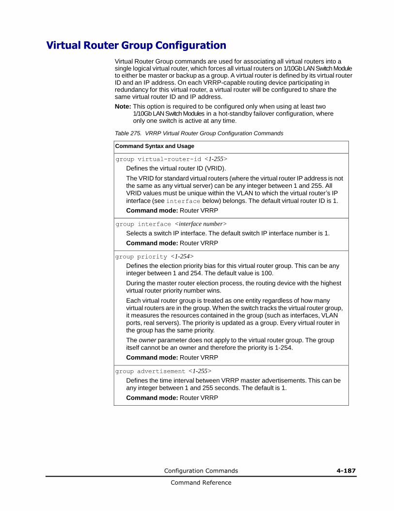
Configuration Commands 4-187
Command Reference
Virtual Router Group Configuration
Virtual Router Group commands are used for associating all virtual routers into a single logical virtual router, which forces all virtual routers on 1/10Gb LAN Switch Module to either be master or backup as a group. A virtual router is defined by its virtual router ID and an IP address. On each VRRP-capable routing device participating in redundancy for this virtual router, a virtual router will be configured to share the same virtual router ID and IP address.
Note: This option is required to be configured only when using at least two 1/10Gb LAN Switch Modules in a hot-standby failover configuration, where only one switch is active at any time.
Table 275. VRRP Virtual Router Group Configuration Commands
Command Syntax and Usage
group virtual-router-id <1-255>
Defines the virtual router ID (VRID).
The VRID for standard virtual routers (where the virtual router IP address is not the same as any virtual server) can be any integer between 1 and 255. All VRID values must be unique within the VLAN to which the virtual router’s IP
interface (see interface below) belongs. The default virtual router ID is 1.
Command mode: Router VRRP
group interface <interface number>
Selects a switch IP interface. The default switch IP interface number is 1.
Command mode: Router VRRP
group priority <1-254>
Defines the election priority bias for this virtual router group. This can be any integer between 1 and 254. The default value is 100.
During the master router election process, the routing device with the highest virtual router priority number wins.
Each virtual router group is treated as one entity regardless of how many virtual routers are in the group. When the switch tracks the virtual router group, it measures the resources contained in the group (such as interfaces, VLAN ports, real servers). The priority is updated as a group. Every virtual router in the group has the same priority.
The owner parameter does not apply to the virtual router group. The group itself cannot be an owner and therefore the priority is 1-254.
Command mode: Router VRRP
group advertisement <1-255>
Defines the time interval between VRRP master advertisements. This can be any integer between 1 and 255 seconds. The default is 1.
Command mode: Router VRRP

4-188 Configuration Commands
Command Reference
Table 275. VRRP Virtual Router Group Configuration Commands (continued)
Command Syntax and Usage
[no] group preemption
Enables or disables master pre-emption. When enabled, if the virtual router group is in backup mode but has a higher priority than the current master, this virtual router will pre-empt the lower priority master and assume control. Note
that even when preemption is disabled, this virtual router will always pre-empt any other master if this switch is the owner (the IP interface address and virtual router address are the same). By default, this option is enabled.
Command mode: Router VRRP
group enable
Enables the virtual router group.
Command mode: Router VRRP
no group enable
Disables the virtual router group.
Command mode: Router VRRP
no group
Deletes the virtual router group from the switch configuration.
Command mode: Router VRRP
show ip vrrp group
Displays the current configuration information for the virtual router group.
Command mode: All
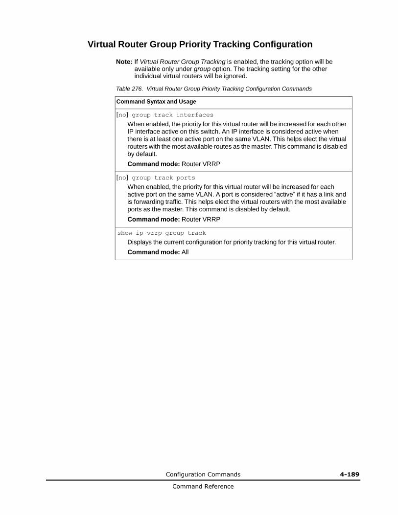
Configuration Commands 4-189
Command Reference
Virtual Router Group Priority Tracking Configuration
Note: If Virtual Router Group Tracking is enabled, the tracking option will be available only under group option. The tracking setting for the other individual virtual routers will be ignored.
Table 276. Virtual Router Group Priority Tracking Configuration Commands
Command Syntax and Usage
[no] group track interfaces
When enabled, the priority for this virtual router will be increased for each other IP interface active on this switch. An IP interface is considered active when there is at least one active port on the same VLAN. This helps elect the virtual routers with the most available routes as the master. This command is disabled by default.
Command mode: Router VRRP
[no] group track ports
When enabled, the priority for this virtual router will be increased for each active port on the same VLAN. A port is considered “active” if it has a link and is forwarding traffic. This helps elect the virtual routers with the most available ports as the master. This command is disabled by default.
Command mode: Router VRRP
show ip vrrp group track
Displays the current configuration for priority tracking for this virtual router.
Command mode: All

4-190 Configuration Commands
Command Reference
VRRP Interface Configuration
Note: The interface represents the IP interface on which authentication parameters must be configured.
These commands are used for configuring VRRP authentication parameters for the IP interfaces used with the virtual routers.
Table 277. VRRP Interface Commands
Command Syntax and Usage
interface <interface number> authentication {password|none}
Defines the type of authentication that will be used: none (no authentication) or password (password authentication).
Command mode: Router VRRP
[no] interface <interface number> password <password>
Defines a plain text password up to eight characters long. This password will be added to each VRRP packet transmitted by this interface when password authentication is chosen (see interface authentication above).
Command mode: Router VRRP
no interface <interface number>
Clears the authentication configuration parameters for this IP interface. The IP interface itself is not deleted.
Command mode: Router VRRP
show ip vrrp interface <interface number>
Displays the current configuration for this IP interface’s authentication parameters.
Command mode: All
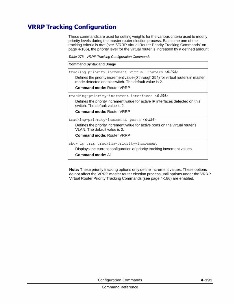
Configuration Commands 4-191
Command Reference
VRRP Tracking Configuration
These commands are used for setting weights for the various criteria used to modify priority levels during the master router election process. Each time one of the tracking criteria is met (see “VRRP Virtual Router Priority Tracking Commands” on page 4-186), the priority level for the virtual router is increased by a defined amount.
Table 278. VRRP Tracking Configuration Commands
Command Syntax and Usage
tracking-priority-increment virtual-routers <0-254>
Defines the priority increment value (0 through 254) for virtual routers in master mode detected on this switch. The default value is 2.
Command mode: Router VRRP
tracking-priority-increment interfaces <0-254>
Defines the priority increment value for active IP interfaces detected on this switch. The default value is 2.
Command mode: Router VRRP
tracking-priority-increment ports <0-254>
Defines the priority increment value for active ports on the virtual router’s VLAN. The default value is 2.
Command mode: Router VRRP
show ip vrrp tracking-priority-increment
Displays the current configuration of priority tracking increment values.
Command mode: All
Note: These priority tracking options only define increment values. These options do not affect the VRRP master router election process until options under the VRRP Virtual Router Priority Tracking Commands (see page 4-186) are enabled.
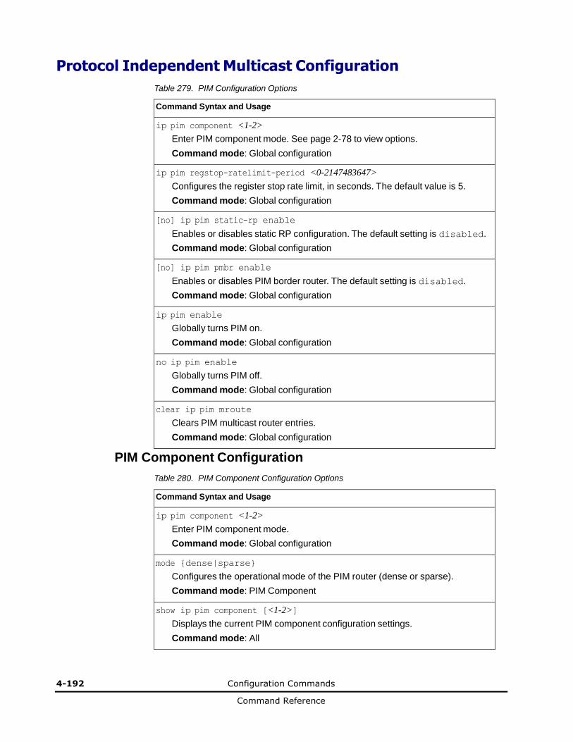
4-192 Configuration Commands
Command Reference
Protocol Independent Multicast Configuration
Table 279. PIM Configuration Options
Command Syntax and Usage
ip pim component <1-2>
Enter PIM component mode. See page 2-78 to view options.
Command mode: Global configuration
ip pim regstop-ratelimit-period <0-2147483647>
Configures the register stop rate limit, in seconds. The default value is 5.
Command mode: Global configuration
[no] ip pim static-rp enable
Enables or disables static RP configuration. The default setting is disabled.
Command mode: Global configuration
[no] ip pim pmbr enable
Enables or disables PIM border router. The default setting is disabled.
Command mode: Global configuration
ip pim enable
Globally turns PIM on.
Command mode: Global configuration
no ip pim enable
Globally turns PIM off.
Command mode: Global configuration
clear ip pim mroute
Clears PIM multicast router entries.
Command mode: Global configuration
PIM Component Configuration
Table 280. PIM Component Configuration Options
Command Syntax and Usage
ip pim component <1-2>
Enter PIM component mode.
Command mode: Global configuration
mode {dense|sparse}
Configures the operational mode of the PIM router (dense or sparse).
Command mode: PIM Component
show ip pim component [<1-2>]
Displays the current PIM component configuration settings.
Command mode: All
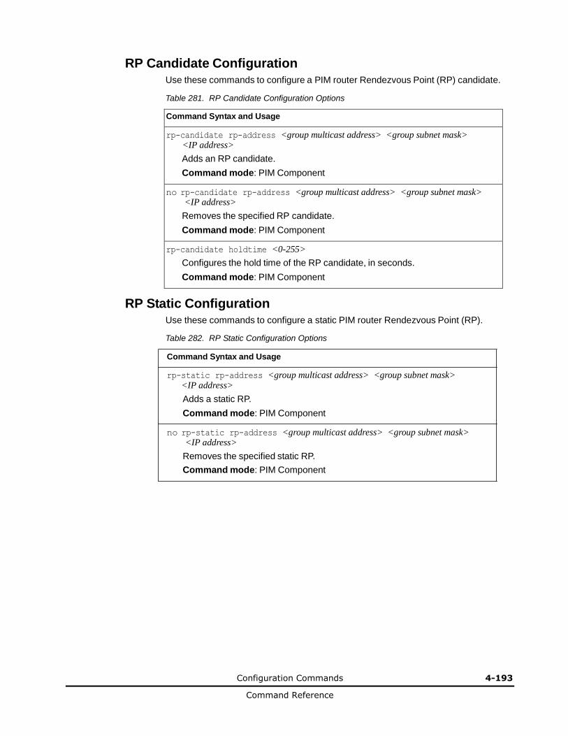
Configuration Commands 4-193
Command Reference
RP Candidate Configuration
Use these commands to configure a PIM router Rendezvous Point (RP) candidate.
Table 281. RP Candidate Configuration Options
Command Syntax and Usage
rp-candidate rp-address <group multicast address> <group subnet mask> <IP address>
Adds an RP candidate.
Command mode: PIM Component
no rp-candidate rp-address <group multicast address> <group subnet mask> <IP address>
Removes the specified RP candidate.
Command mode: PIM Component
rp-candidate holdtime <0-255>
Configures the hold time of the RP candidate, in seconds.
Command mode: PIM Component
RP Static Configuration
Use these commands to configure a static PIM router Rendezvous Point (RP).
Table 282. RP Static Configuration Options
Command Syntax and Usage
rp-static rp-address <group multicast address> <group subnet mask> <IP address>
Adds a static RP.
Command mode: PIM Component
no rp-static rp-address <group multicast address> <group subnet mask> <IP address>
Removes the specified static RP.
Command mode: PIM Component

4-194 Configuration Commands
Command Reference
PIM Interface Configuration
Table 283. PIM Interface Configuration Options
Command Syntax and Usage
interface ip <interface number>
Enter Interface IP mode.
Command mode: Global Configuration
ip pim hello-interval <0-65535>
Configures the time interval, in seconds, between PIM Hello packets. The default value is 30.
Command mode: Interface IP
ip pim join-prune-interval <0-65535>
Configures the interval between Join Prune messages, in seconds. The default value is 60.
Command mode: Interface IP
[no] ip pim cbsr-preference <0-255>
Configures the candidate bootstrap router preference.
Command mode: Interface IP
ip pim component-id <1-2>
Defines the component ID for the interface.
Command mode: Interface IP
ip pim hello-holdtime <1-65535>
Configures the time period for which a neighbor is to consider this switch to be operative (up). The default value is 105.
Command mode: Interface IP
ip pim dr-priority <0-4294967294>
Configures the designated router priority. The default value is 1.
Command mode: Interface IP
ip pim override-interval <0-65535>
Configures the override interval for the router interface, in seconds.
Command mode: Interface IP
ip pim lan-delay <0-32767>
Configures the LAN delay value for the router interface, in seconds.
Command mode: Interface IP
[no] ip pim border-bit
Enables or disables the interface as a border router. The default setting is
disabled.
Command mode: Interface IP
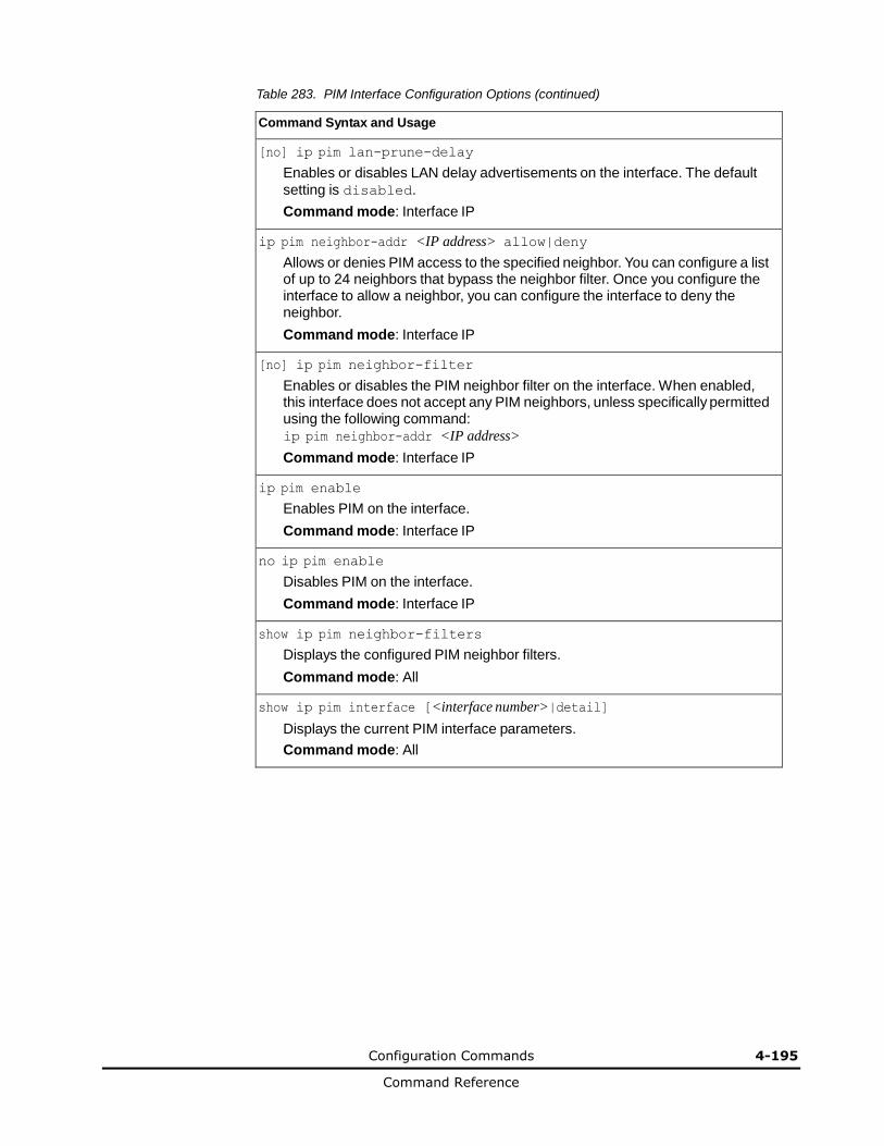
Configuration Commands 4-195
Command Reference
Table 283. PIM Interface Configuration Options (continued)
Command Syntax and Usage
[no] ip pim lan-prune-delay
Enables or disables LAN delay advertisements on the interface. The default
setting is disabled.
Command mode: Interface IP
ip pim neighbor-addr <IP address> allow|deny
Allows or denies PIM access to the specified neighbor. You can configure a list of up to 24 neighbors that bypass the neighbor filter. Once you configure the interface to allow a neighbor, you can configure the interface to deny the neighbor.
Command mode: Interface IP
[no] ip pim neighbor-filter
Enables or disables the PIM neighbor filter on the interface. When enabled, this interface does not accept any PIM neighbors, unless specifically permitted using the following command: ip pim neighbor-addr <IP address>
Command mode: Interface IP
ip pim enable
Enables PIM on the interface.
Command mode: Interface IP
no ip pim enable
Disables PIM on the interface.
Command mode: Interface IP
show ip pim neighbor-filters
Displays the configured PIM neighbor filters.
Command mode: All
show ip pim interface [<interface number>|detail]
Displays the current PIM interface parameters.
Command mode: All
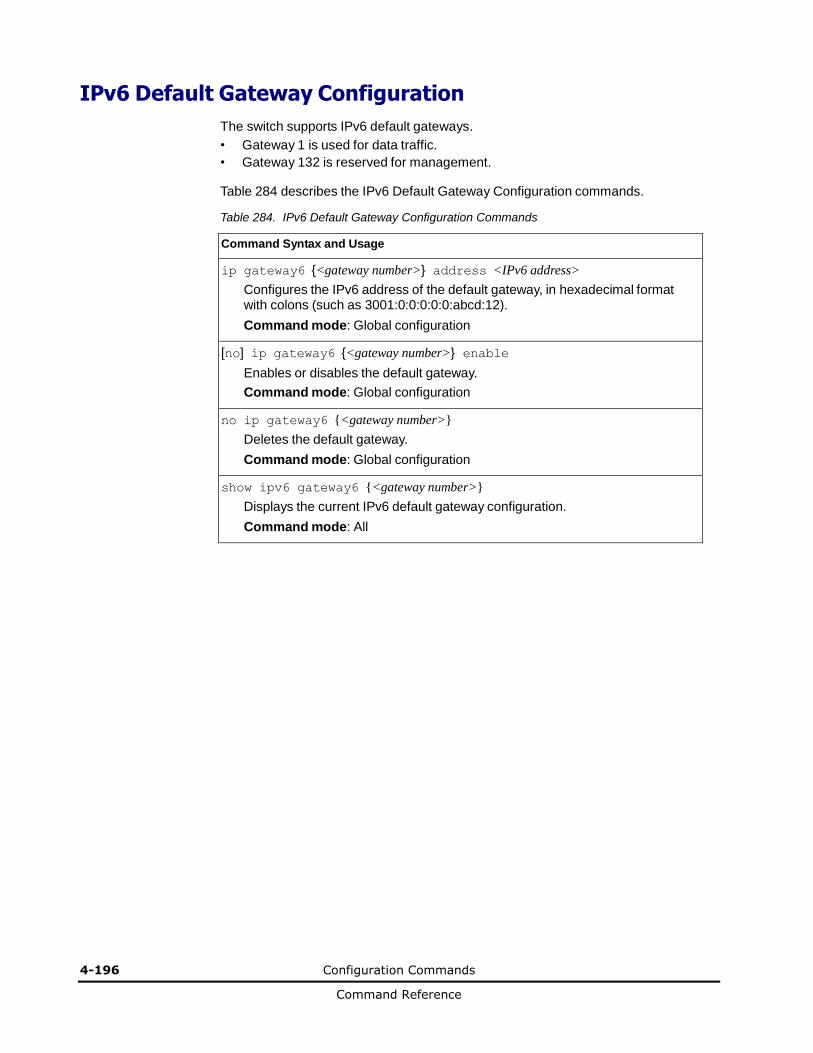
4-196 Configuration Commands
Command Reference
IPv6 Default Gateway Configuration
The switch supports IPv6 default gateways.
• Gateway 1 is used for data traffic.
• Gateway 132 is reserved for management.
Table 284 describes the IPv6 Default Gateway Configuration commands.
Table 284. IPv6 Default Gateway Configuration Commands
Command Syntax and Usage
ip gateway6 {<gateway number>} address <IPv6 address>
Configures the IPv6 address of the default gateway, in hexadecimal format with colons (such as 3001:0:0:0:0:0:abcd:12).
Command mode: Global configuration
[no] ip gateway6 {<gateway number>} enable
Enables or disables the default gateway.
Command mode: Global configuration
no ip gateway6 {<gateway number>}
Deletes the default gateway.
Command mode: Global configuration
show ipv6 gateway6 {<gateway number>}
Displays the current IPv6 default gateway configuration.
Command mode: All
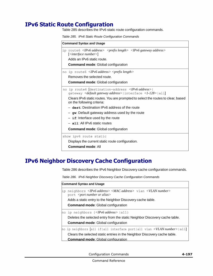
Configuration Commands 4-197
Command Reference
IPv6 Static Route Configuration Table 285 describes the IPv6 static route configuration commands.
Table 285. IPv6 Static Route Configuration Commands
Command Syntax and Usage
ip route6 <IPv6 address> <prefix length> <IPv6 gateway address> [<interface number>]
Adds an IPv6 static route.
Command mode: Global configuration
no ip route6 <IPv6 address> <prefix length>
Removes the selected route.
Command mode: Global configuration
no ip route6 [destination-address <IPv6 address>| gateway <default gateway address>|interface <1-128>|all]
Clears IPv6 static routes. You are prompted to select the routes to clear, based on the following criteria:
– dest: Destination IPv6 address of the route
– gw: Default gateway address used by the route
– if: Interface used by the route
– all: All IPv6 static routes
Command mode: Global configuration
show ipv6 route static
Displays the current static route configuration.
Command mode: All
IPv6 Neighbor Discovery Cache Configuration
Table 286 describes the IPv6 Neighbor Discovery cache configuration commands.
Table 286. IPv6 Neighbor Discovery Cache Configuration Commands
Command Syntax and Usage
ip neighbors <IPv6 address> <MAC address> vlan <VLAN number> port <port number or alias>
Adds a static entry to the Neighbor Discovery cache table.
Command mode: Global configuration
no ip neighbors {<IPv6 address> |all}
Deletes the selected entry from the static Neighbor Discovery cache table.
Command mode: Global configuration
no ip neighbors [all if|all interface port|all vlan <VLAN number>|all]
Clears the selected static entries in the Neighbor Discovery cache table.
Command mode: Global configuration
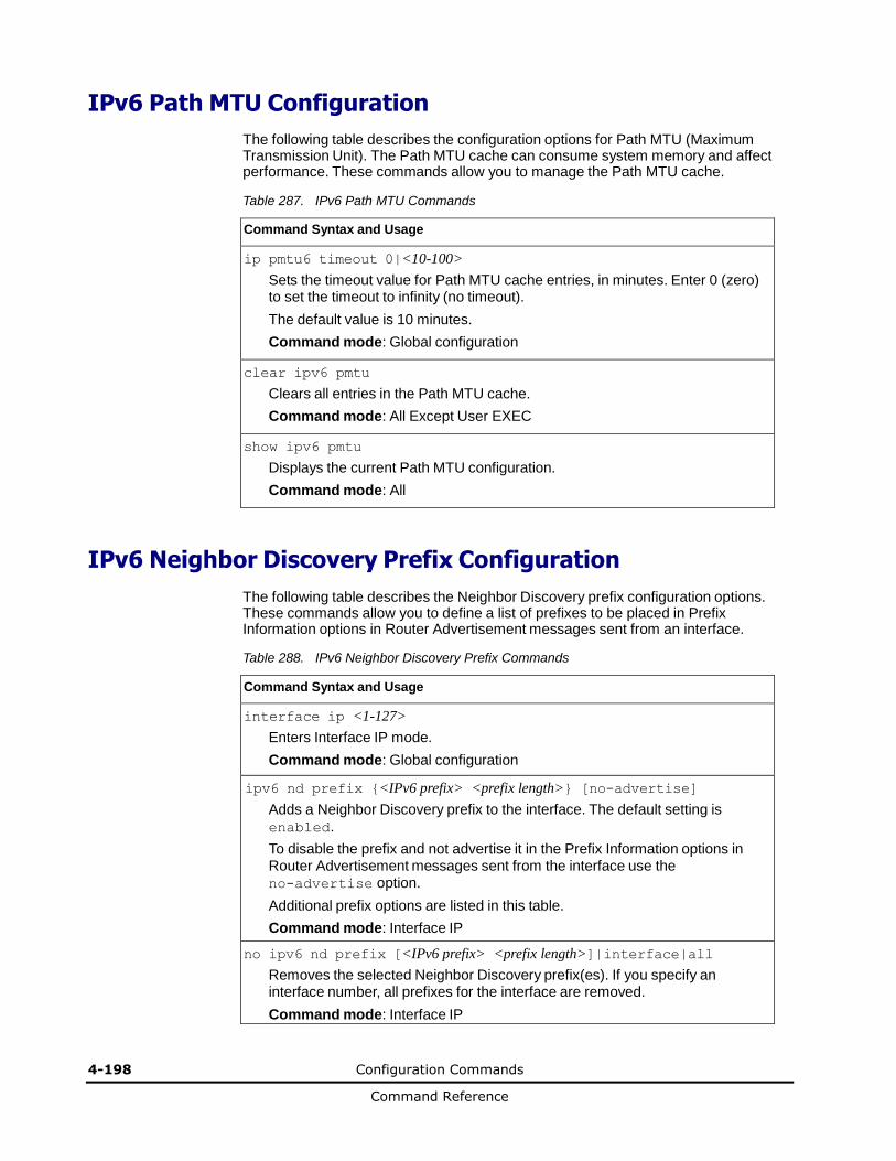
4-198 Configuration Commands
Command Reference
IPv6 Path MTU Configuration
The following table describes the configuration options for Path MTU (Maximum Transmission Unit). The Path MTU cache can consume system memory and affect performance. These commands allow you to manage the Path MTU cache.
Table 287. IPv6 Path MTU Commands
Command Syntax and Usage
ip pmtu6 timeout 0|<10-100>
Sets the timeout value for Path MTU cache entries, in minutes. Enter 0 (zero) to set the timeout to infinity (no timeout).
The default value is 10 minutes.
Command mode: Global configuration
clear ipv6 pmtu
Clears all entries in the Path MTU cache.
Command mode: All Except User EXEC
show ipv6 pmtu
Displays the current Path MTU configuration.
Command mode: All
IPv6 Neighbor Discovery Prefix Configuration The following table describes the Neighbor Discovery prefix configuration options. These commands allow you to define a list of prefixes to be placed in Prefix Information options in Router Advertisement messages sent from an interface.
Table 288. IPv6 Neighbor Discovery Prefix Commands
Command Syntax and Usage
interface ip <1-127>
Enters Interface IP mode.
Command mode: Global configuration
ipv6 nd prefix {<IPv6 prefix> <prefix length>} [no-advertise]
Adds a Neighbor Discovery prefix to the interface. The default setting is
enabled.
To disable the prefix and not advertise it in the Prefix Information options in Router Advertisement messages sent from the interface use the no-advertise option.
Additional prefix options are listed in this table.
Command mode: Interface IP
no ipv6 nd prefix [<IPv6 prefix> <prefix length>]|interface|all
Removes the selected Neighbor Discovery prefix(es). If you specify an interface number, all prefixes for the interface are removed.
Command mode: Interface IP

Configuration Commands 4-199
Command Reference
Table 288. IPv6 Neighbor Discovery Prefix Commands (continued)
Command Syntax and Usage
ipv6 nd prefix {<IPv6 prefix> <prefix length>} valid-lifetime <0-4294967295> [infinite|variable} prefered-lifetime <0-4294967295> [infinite|variable}
Configures the Valid Lifetime and (optionally) the Preferred Lifetime of the prefix, in seconds.
The Valid Lifetime is the length of time (relative to the time the packet is sent) that the prefix is valid for the purpose of on-link determination. The default value is 2592000.
The Preferred Lifetime is the length of time (relative to the time the packet is sent) that addresses generated from the prefix via stateless address autoconfiguration remain preferred. The default value is 604800.
Note: The Preferred Lifetime value must not exceed the Valid Lifetime value.
Command mode: Interface IP
ipv6 nd prefix {<IPv6 prefix> <prefix length>} off-link [no-autoconfig]
Disables the on-link flag. When enabled, the on-link flag indicates that this prefix can be used for on-link determination. When disabled, the advertisement makes no statement about on-link or off-link properties of the prefix. The
default setting is enabled.
To clear the off-link flag, omit the off-link parameter when you issue this command.
Command mode: Interface IP
ipv6 nd prefix {<IPv6 prefix> <prefix length>} no-autoconfig
Disables the autonomous flag. When enabled, the autonomous flag indicates that the prefix can be used for stateless address configuration. The default setting is enabled.
Command mode: Interface IP
show ipv6 prefix {<interface number>}
Displays current Neighbor Discovery prefix parameters.
Command mode: All
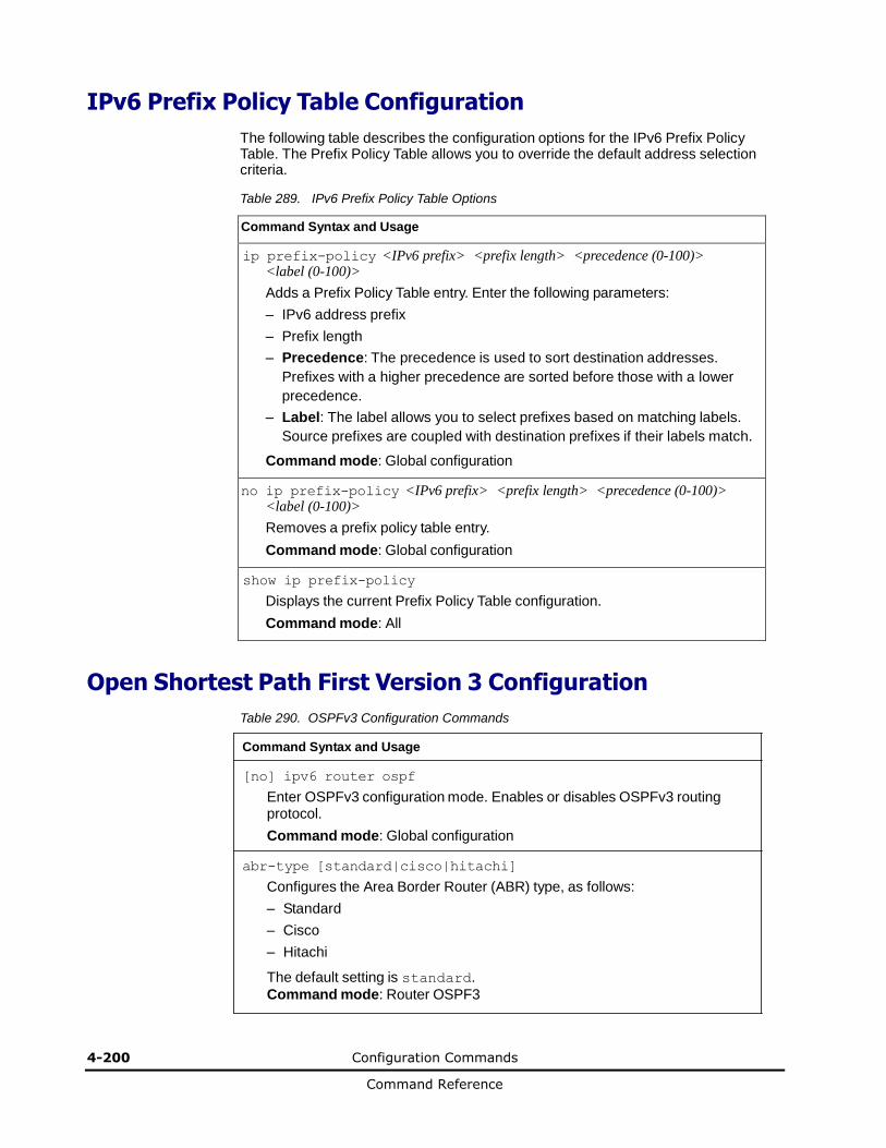
4-200 Configuration Commands
Command Reference
IPv6 Prefix Policy Table Configuration
The following table describes the configuration options for the IPv6 Prefix Policy Table. The Prefix Policy Table allows you to override the default address selection criteria.
Table 289. IPv6 Prefix Policy Table Options
Command Syntax and Usage
ip prefix-policy <IPv6 prefix> <prefix length> <precedence (0-100)> <label (0-100)>
Adds a Prefix Policy Table entry. Enter the following parameters:
– IPv6 address prefix
– Prefix length
– Precedence: The precedence is used to sort destination addresses.
Prefixes with a higher precedence are sorted before those with a lower
precedence.
– Label: The label allows you to select prefixes based on matching labels.
Source prefixes are coupled with destination prefixes if their labels match.
Command mode: Global configuration
no ip prefix-policy <IPv6 prefix> <prefix length> <precedence (0-100)> <label (0-100)>
Removes a prefix policy table entry.
Command mode: Global configuration
show ip prefix-policy
Displays the current Prefix Policy Table configuration.
Command mode: All
Open Shortest Path First Version 3 Configuration
Table 290. OSPFv3 Configuration Commands
Command Syntax and Usage
[no] ipv6 router ospf
Enter OSPFv3 configuration mode. Enables or disables OSPFv3 routing protocol.
Command mode: Global configuration
abr-type [standard|cisco|hitachi]
Configures the Area Border Router (ABR) type, as follows:
– Standard
– Cisco
– Hitachi
The default setting is standard.
Command mode: Router OSPF3

Configuration Commands 4-201
Command Reference
Table 290. OSPFv3 Configuration Commands (continued)
Command Syntax and Usage
as-external lsdb-limit <LSDB limit (0-2147483647, -1 for no limit)>
Sets the link state database limit.
Command mode: Router OSPF3
exit-overflow-interval <0-4294967295>
Configures the number of seconds that a router takes to exit Overflow State. The default value is 0 (zero).
Command mode: Router OSPF3
neighbor <1-256> {address <IPv6 address>|enable|interface <1-126>| priority <0-255>}
Configures directly reachable routers over non-broadcast networks.This is required for non-broadcast multiple access (NBMA) networks and optional for Point-to-Multipoint networks.
– address configures the neighbor’s IPv6 address
– enable activates a previously disabled neighbor
– interface configures the OSPFv3 interface used for the neighbor entry
– priority configures the priority value used for the neighbor entry. A
priority value of 255 is the highest and 1 is the lowest. A priority value of 0
specifies that the neighbor cannot be used as Designated Router. The
default value is 1.
Command mode: Router OSPF3
no neighbor <1-256> [enable]
Deletes the neighbor entry.
Using the enable option only disables the neighbor, while preserving it’s settings.
Command mode: Router OSPF3
reference-bandwidth <0-4294967295>
Configures the reference bandwidth, in kilobits per second, used to calculate the default interface metric. The default value is 100,000.
Command mode: Router OSPF3
timers spf {<SPF delay (0-65535)>} {<SPF hold time (0-65535)>}
Configures the number of seconds that SPF calculation is delayed after a topology change message is received. The default value is 5.
Configures the number of seconds between SPF calculations. The default value is 10.
Command mode: Router OSPF3
router-id <IPv4 address>
Defines the router ID.
Command mode: Router OSPF3
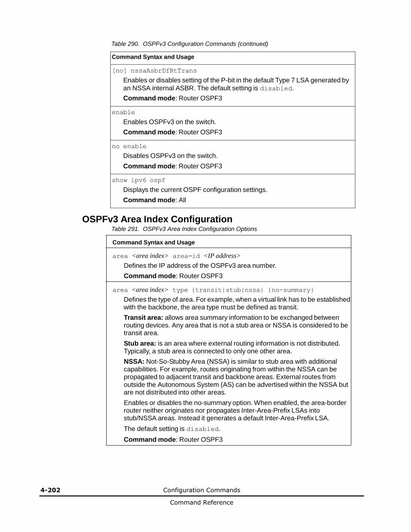
4-202 Configuration Commands
Command Reference
Table 290. OSPFv3 Configuration Commands (continued)
Command Syntax and Usage
[no] nssaAsbrDfRtTrans
Enables or disables setting of the P-bit in the default Type 7 LSA generated by
an NSSA internal ASBR. The default setting is disabled.
Command mode: Router OSPF3
enable
Enables OSPFv3 on the switch.
Command mode: Router OSPF3
no enable
Disables OSPFv3 on the switch.
Command mode: Router OSPF3
show ipv6 ospf
Displays the current OSPF configuration settings.
Command mode: All
OSPFv3 Area Index Configuration Table 291. OSPFv3 Area Index Configuration Options
Command Syntax and Usage
area <area index> area-id <IP address>
Defines the IP address of the OSPFv3 area number.
Command mode: Router OSPF3
area <area index> type {transit|stub|nssa} {no-summary}
Defines the type of area. For example, when a virtual link has to be established with the backbone, the area type must be defined as transit.
Transit area: allows area summary information to be exchanged between routing devices. Any area that is not a stub area or NSSA is considered to be transit area.
Stub area: is an area where external routing information is not distributed. Typically, a stub area is connected to only one other area.
NSSA: Not-So-Stubby Area (NSSA) is similar to stub area with additional capabilities. For example, routes originating from within the NSSA can be propagated to adjacent transit and backbone areas. External routes from outside the Autonomous System (AS) can be advertised within the NSSA but are not distributed into other areas.
Enables or disables the no-summary option. When enabled, the area-border router neither originates nor propagates Inter-Area-Prefix LSAs into stub/NSSA areas. Instead it generates a default Inter-Area-Prefix LSA.
The default setting is disabled.
Command mode: Router OSPF3
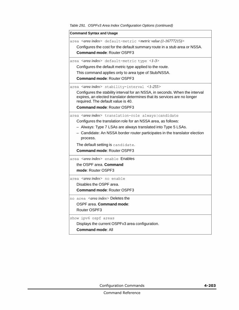
Configuration Commands 4-203
Command Reference
Table 291. OSPFv3 Area Index Configuration Options (continued)
Command Syntax and Usage
area <area index> default-metric <metric value (1-16777215)>
Configures the cost for the default summary route in a stub area or NSSA.
Command mode: Router OSPF3
area <area index> default-metric type <1-3>
Configures the default metric type applied to the route.
This command applies only to area type of Stub/NSSA.
Command mode: Router OSPF3
area <area index> stability-interval <1-255>
Configures the stability interval for an NSSA, in seconds. When the interval expires, an elected translator determines that its services are no longer required. The default value is 40.
Command mode: Router OSPF3
area <area index> translation-role always|candidate
Configures the translation role for an NSSA area, as follows:
– Always: Type 7 LSAs are always translated into Type 5 LSAs.
– Candidate: An NSSA border router participates in the translator election
process.
The default setting is candidate.
Command mode: Router OSPF3
area <area index> enable Enables
the OSPF area. Command
mode: Router OSPF3
area <area index> no enable
Disables the OSPF area.
Command mode: Router OSPF3
no area <area index> Deletes the
OSPF area. Command mode:
Router OSPF3
show ipv6 ospf areas
Displays the current OSPFv3 area configuration.
Command mode: All

4-204 Configuration Commands
Command Reference
OSPFv3 Summary Range Configuration Table 292. OSPFv3 Summary Range Configuration Options
Command Syntax and Usage
area-range <1-16> address <IPv6 address> <prefix length (1-128)>
Configures the base IPv6 address and subnet prefix length for the range.
Command mode: Router OSPF3
area-range <1-16> area <area index (0-2)>
Configures the area index used by the switch.
Command mode: Router OSPF3
area-range <1-16> lsa-type summary|Type7
Configures the LSA type, as follows:
– Summary LSA
– Type7 LSA
Command mode: Router OSPF3
area-range <1-16> tag <0-4294967295>
Configures the route tag.
Command mode: Router OSPF3
[no] area-range <1-16> hide
Hides the OSPFv3 summary range.
Command mode: Router OSPF3
area-range <1-16> enable
Enables the OSPFv3 summary range.
Command mode: Router OSPF3
area-range <1-16> no enable
Disables the OSPFv3 summary range.
Command mode: Router OSPF3
no area-range <1-16>
Deletes the OSPFv3 summary range.
Command mode: Router OSPF3
show ipv6 ospf area-range
Displays the current OSPFv3 summary range.
Command mode: All
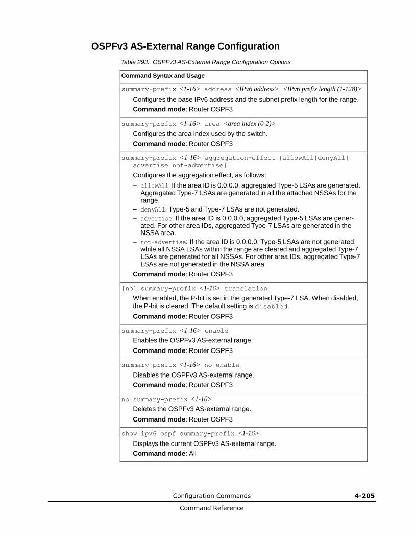
Configuration Commands 4-205
Command Reference
OSPFv3 AS-External Range Configuration
Table 293. OSPFv3 AS-External Range Configuration Options
Command Syntax and Usage
summary-prefix <1-16> address <IPv6 address> <IPv6 prefix length (1-128)>
Configures the base IPv6 address and the subnet prefix length for the range.
Command mode: Router OSPF3
summary-prefix <1-16> area <area index (0-2)>
Configures the area index used by the switch.
Command mode: Router OSPF3
summary-prefix <1-16> aggregation-effect {allowAll|denyAll| advertise|not-advertise}
Configures the aggregation effect, as follows:
– allowAll: If the area ID is 0.0.0.0, aggregated Type-5 LSAs are generated. Aggregated Type-7 LSAs are generated in all the attached NSSAs for the range.
– denyAll: Type-5 and Type-7 LSAs are not generated.
– advertise: If the area ID is 0.0.0.0, aggregated Type-5 LSAs are gener- ated. For other area IDs, aggregated Type-7 LSAs are generated in the NSSA area.
– not-advertise: If the area ID is 0.0.0.0, Type-5 LSAs are not generated, while all NSSA LSAs within the range are cleared and aggregated Type-7 LSAs are generated for all NSSAs. For other area IDs, aggregated Type-7 LSAs are not generated in the NSSA area.
Command mode: Router OSPF3
[no] summary-prefix <1-16> translation
When enabled, the P-bit is set in the generated Type-7 LSA. When disabled, the P-bit is cleared. The default setting is disabled.
Command mode: Router OSPF3
summary-prefix <1-16> enable
Enables the OSPFv3 AS-external range.
Command mode: Router OSPF3
summary-prefix <1-16> no enable
Disables the OSPFv3 AS-external range.
Command mode: Router OSPF3
no summary-prefix <1-16>
Deletes the OSPFv3 AS-external range.
Command mode: Router OSPF3
show ipv6 ospf summary-prefix <1-16>
Displays the current OSPFv3 AS-external range.
Command mode: All
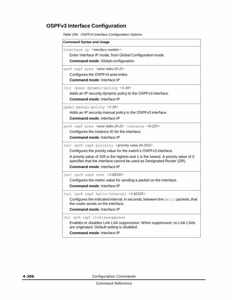
4-206 Configuration Commands
Command Reference
OSPFv3 Interface Configuration
Table 294. OSPFv3 Interface Configuration Options
Command Syntax and Usage
interface ip <interface number>
Enter Interface IP mode, from Global Configuration mode.
Command mode: Global configuration
ipv6 ospf area <area index (0-2)>
Configures the OSPFv3 area index.
Command mode: Interface IP
[no] ipsec dynamic-policy <1-10>
Adds an IP security dynamic policy to the OSPFv3 interface.
Command mode: Interface IP
ipsec manual-policy <1-10>
Adds an IP security manual policy to the OSPFv3 interface.
Command mode: Interface IP
ipv6 ospf area <area index (0-2)> instance <0-255>
Configures the instance ID for the interface.
Command mode: Interface IP
[no] ipv6 ospf priority <priority value (0-255)>
Configures the priority value for the switch’s OSPFv3 interface.
A priority value of 255 is the highest and 1 is the lowest. A priority value of 0 specifies that the interface cannot be used as Designated Router (DR).
Command mode: Interface IP
[no] ipv6 ospf cost <1-65535>
Configures the metric value for sending a packet on the interface.
Command mode: Interface IP
[no] ipv6 ospf hello-interval <1-65535>
Configures the indicated interval, in seconds, between the hello packets, that the router sends on the interface.
Command mode: Interface IP
[no] ipv6 ospf linklsasuppress
Enables or disables Link LSA suppression. When suppressed, no Link LSAs are originated. Default setting is disabled.
Command mode: Interface IP
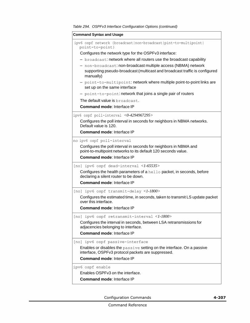
Configuration Commands 4-207
Command Reference
Table 294. OSPFv3 Interface Configuration Options (continued)
Command Syntax and Usage
ipv6 ospf network {broadcast|non-broadcast|pint-to-multipoint|
point-to-point}
Configures the network type for the OSPFv3 interface:
– broadcast: network where all routers use the broadcast capability
– non-broadcast: non-broadcast multiple access (NBMA) network
supporting pseudo-broadcast (multicast and broadcast traffic is configured
manually)
– point-to-multipoint: network where multiple point-to-point links are
set up on the same interface
– point-to-point: network that joins a single pair of routers
The default value is broadcast.
Command mode: Interface IP
ipv6 ospf poll-interval <0-4294967295>
Configures the poll interval in seconds for neighbors in NBMA networks. Default value is 120.
Command mode: Interface IP
no ipv6 ospf poll-interval
Configures the poll interval in seconds for neighbors in NBMA and point-to-multipoint networks to its default 120 seconds value.
Command mode: Interface IP
[no] ipv6 ospf dead-interval <1-65535>
Configures the health parameters of a hello packet, in seconds, before declaring a silent router to be down.
Command mode: Interface IP
[no] ipv6 ospf transmit-delay <1-1800>
Configures the estimated time, in seconds, taken to transmit LS update packet over this interface.
Command mode: Interface IP
[no] ipv6 ospf retransmit-interval <1-1800>
Configures the interval in seconds, between LSA retransmissions for adjacencies belonging to interface.
Command mode: Interface IP
[no] ipv6 ospf passive-interface
Enables or disables the passive setting on the interface. On a passive interface, OSPFv3 protocol packets are suppressed.
Command mode: Interface IP
ipv6 ospf enable
Enables OSPFv3 on the interface.
Command mode: Interface IP

4-208 Configuration Commands
Command Reference
Table 294. OSPFv3 Interface Configuration Options (continued)
Command Syntax and Usage
ipv6 ospf no enable
Disables OSPFv3 on the interface.
Command mode: Interface IP
no ipv6 ospf
Deletes OSPFv3 from interface.
Command mode: Interface IP
show ipv6 ospf interface
Displays the current settings for OSPFv3 interface.
Command mode: Interface IP
OSPFv3 over IPSec Configuration
The following table describes the OSPFv3 over IPsec Configuration commands.
Table 295. Layer 3 IPsec Configuration Options
Command Syntax and Usage
ipv6 ospf authentication ipsec spi <256-4294967295> {md5|sha1} <authentication key (hexadecimal)>
Configures the Security Parameters Index (SPI), algorithm, and authentication key for the Authentication Header (AH). The algorithms supported are:
– MD5 (hexadecimal key length is 32)
– SHA1 (hexadecimal key length is 40)
Command mode: Interface IP
[no] ipv6 ospf authentication ipsec enable
Enables or disables IPsec.
Command mode: Interface IP
no ipv6 ospf authentication ipsec spi <256-4294967295>
Disables the specified Authentication Header (AH) SPI.
Command mode: Interface IP
ipv6 ospf authentication ipsec default
Resets the Authentication Header (AH) configuration to default values.
Command mode: Interface IP
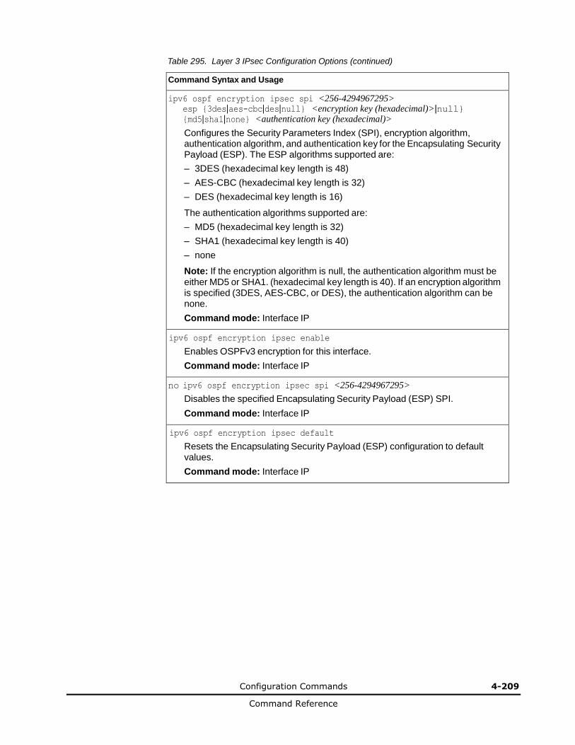
Configuration Commands 4-209
Command Reference
Table 295. Layer 3 IPsec Configuration Options (continued)
Command Syntax and Usage
ipv6 ospf encryption ipsec spi <256-4294967295> esp {3des|aes-cbc|des|null} <encryption key (hexadecimal)>|null} {md5|sha1|none} <authentication key (hexadecimal)>
Configures the Security Parameters Index (SPI), encryption algorithm, authentication algorithm, and authentication key for the Encapsulating Security Payload (ESP). The ESP algorithms supported are:
– 3DES (hexadecimal key length is 48)
– AES-CBC (hexadecimal key length is 32)
– DES (hexadecimal key length is 16)
The authentication algorithms supported are:
– MD5 (hexadecimal key length is 32)
– SHA1 (hexadecimal key length is 40)
– none
Note: If the encryption algorithm is null, the authentication algorithm must be either MD5 or SHA1. (hexadecimal key length is 40). If an encryption algorithm is specified (3DES, AES-CBC, or DES), the authentication algorithm can be none.
Command mode: Interface IP
ipv6 ospf encryption ipsec enable
Enables OSPFv3 encryption for this interface.
Command mode: Interface IP
no ipv6 ospf encryption ipsec spi <256-4294967295>
Disables the specified Encapsulating Security Payload (ESP) SPI.
Command mode: Interface IP
ipv6 ospf encryption ipsec default
Resets the Encapsulating Security Payload (ESP) configuration to default values.
Command mode: Interface IP
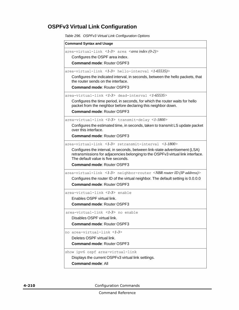
4-210 Configuration Commands
Command Reference
OSPFv3 Virtual Link Configuration
Table 296. OSPFv3 Virtual Link Configuration Options
Command Syntax and Usage
area-virtual-link <1-3> area <area index (0-2)>
Configures the OSPF area index.
Command mode: Router OSPF3
area-virtual-link <1-3> hello-interval <1-65535)>
Configures the indicated interval, in seconds, between the hello packets, that the router sends on the interface.
Command mode: Router OSPF3
area-virtual-link <1-3> dead-interval <1-65535>
Configures the time period, in seconds, for which the router waits for hello packet from the neighbor before declaring this neighbor down.
Command mode: Router OSPF3
area-virtual-link <1-3> transmit-delay <1-1800>
Configures the estimated time, in seconds, taken to transmit LS update packet over this interface.
Command mode: Router OSPF3
area-virtual-link <1-3> retransmit-interval <1-1800>
Configures the interval, in seconds, between link-state advertisement (LSA) retransmissions for adjacencies belonging to the OSPFv3 virtual link interface. The default value is five seconds.
Command mode: Router OSPF3
area-virtual-link <1-3> neighbor-router <NBR router ID (IP address)>
Configures the router ID of the virtual neighbor. The default setting is 0.0.0.0
Command mode: Router OSPF3
area-virtual-link <1-3> enable
Enables OSPF virtual link.
Command mode: Router OSPF3
area-virtual-link <1-3> no enable
Disables OSPF virtual link.
Command mode: Router OSPF3
no area-virtual-link <1-3>
Deletes OSPF virtual link.
Command mode: Router OSPF3
show ipv6 ospf area-virtual-link
Displays the current OSPFv3 virtual link settings.
Command mode: All

Configuration Commands 4-211
Command Reference
OSPFv3 Host Entry Configuration
Table 297. OSPFv3 Host Entry Configuration Options
Command Syntax and Usage
host <1-128> address <IPv6 address> <prefix length (1-128)>
Configures the base IPv6 address and the subnet prefix length for the host entry.
Command mode: Router OSPF3
host <1-128> area <area index (0-2)>
Configures the area index of the host.
Command mode: Router OSPF3
host <1-128> cost <1-65535>
Configures the cost value of the host.
Command mode: Router OSPF3
host <1-128> enable
Enables the host entry.
Command mode: Router OSPF3
no host <1-128> enable Disables
the host entry. Command mode:
Router OSPF3
no host <1-128>
Deletes the host entry.
Command mode: Router OSPF3
show ipv6 ospf host [<1-128>]
Displays the current OSPFv3 host entries.
Command mode: All
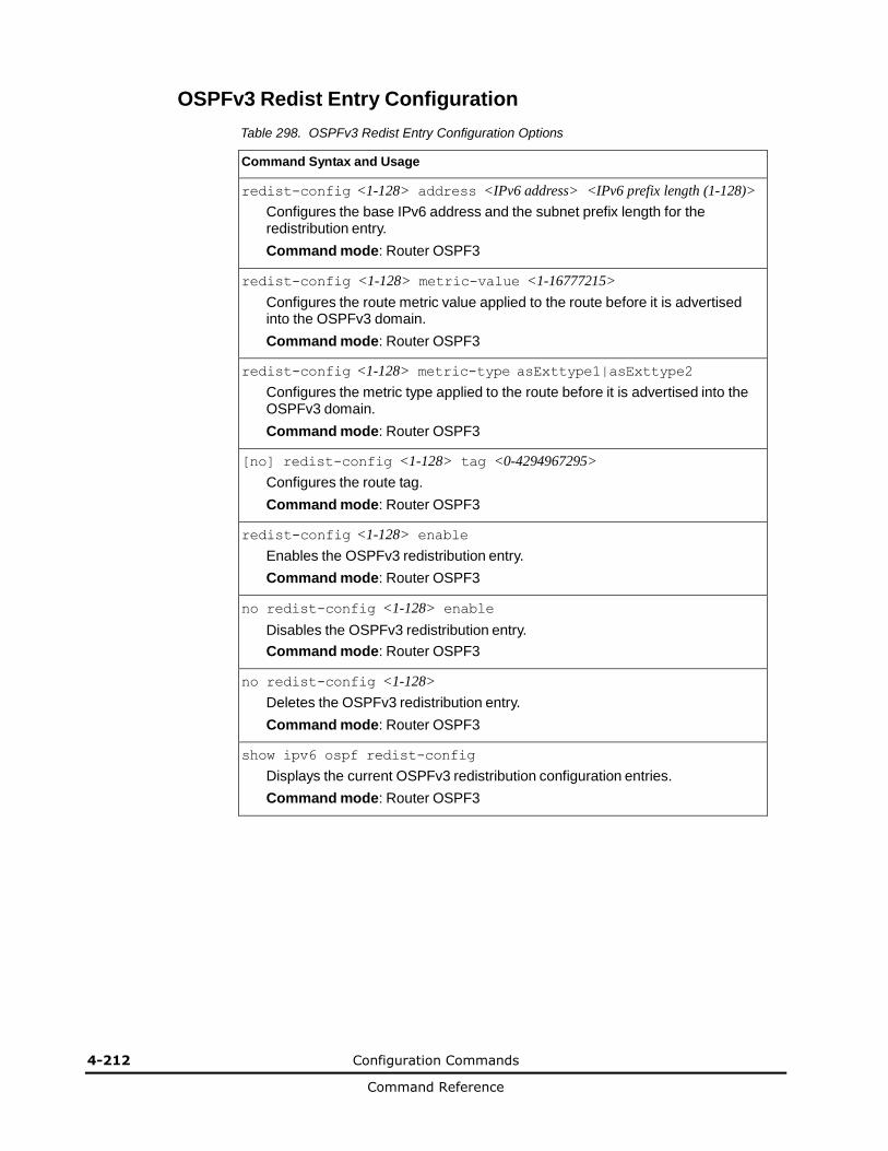
4-212 Configuration Commands
Command Reference
OSPFv3 Redist Entry Configuration
Table 298. OSPFv3 Redist Entry Configuration Options
Command Syntax and Usage
redist-config <1-128> address <IPv6 address> <IPv6 prefix length (1-128)>
Configures the base IPv6 address and the subnet prefix length for the redistribution entry.
Command mode: Router OSPF3
redist-config <1-128> metric-value <1-16777215>
Configures the route metric value applied to the route before it is advertised into the OSPFv3 domain.
Command mode: Router OSPF3
redist-config <1-128> metric-type asExttype1|asExttype2
Configures the metric type applied to the route before it is advertised into the OSPFv3 domain.
Command mode: Router OSPF3
[no] redist-config <1-128> tag <0-4294967295>
Configures the route tag.
Command mode: Router OSPF3
redist-config <1-128> enable
Enables the OSPFv3 redistribution entry.
Command mode: Router OSPF3
no redist-config <1-128> enable
Disables the OSPFv3 redistribution entry.
Command mode: Router OSPF3
no redist-config <1-128>
Deletes the OSPFv3 redistribution entry.
Command mode: Router OSPF3
show ipv6 ospf redist-config
Displays the current OSPFv3 redistribution configuration entries.
Command mode: Router OSPF3
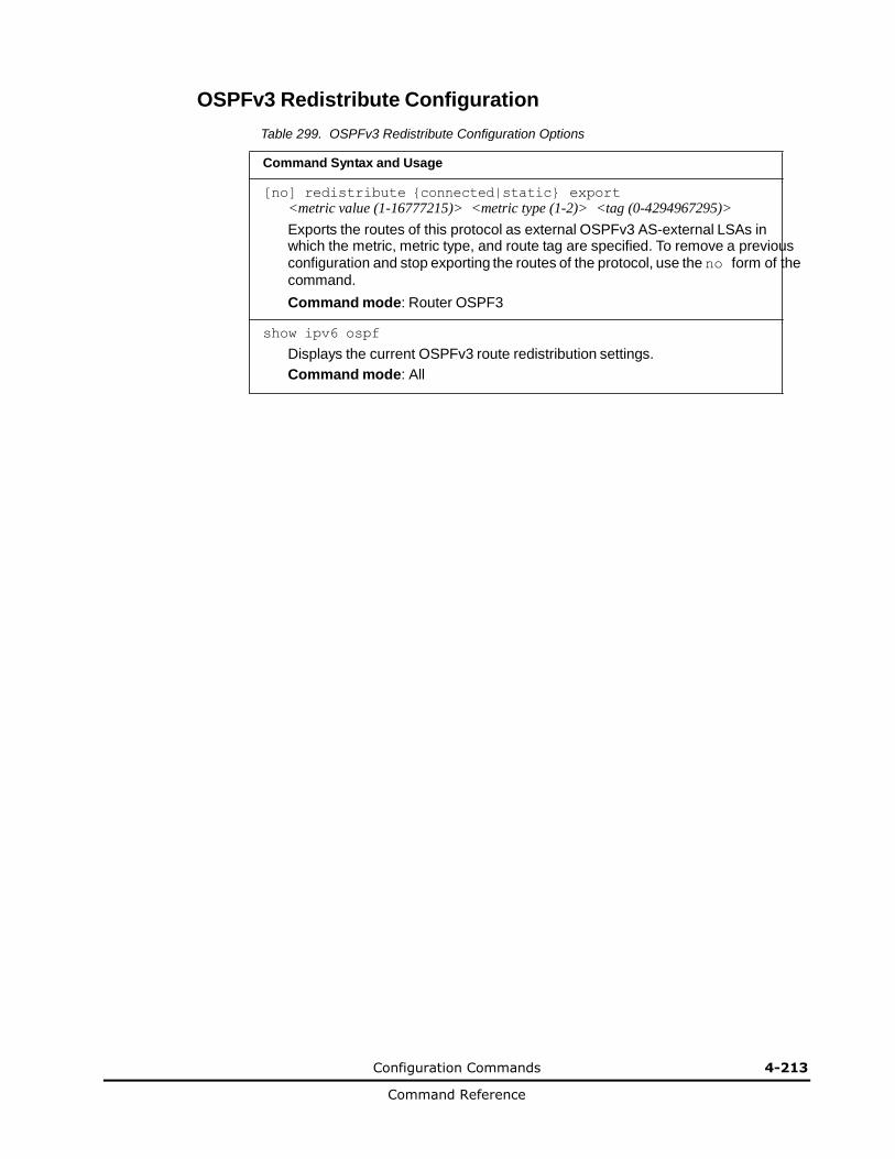
Configuration Commands 4-213
Command Reference
OSPFv3 Redistribute Configuration
Table 299. OSPFv3 Redistribute Configuration Options
Command Syntax and Usage
[no] redistribute {connected|static} export
<metric value (1-16777215)> <metric type (1-2)> <tag (0-4294967295)>
Exports the routes of this protocol as external OSPFv3 AS-external LSAs in which the metric, metric type, and route tag are specified. To remove a previous configuration and stop exporting the routes of the protocol, use the no form of the
command.
Command mode: Router OSPF3
show ipv6 ospf
Displays the current OSPFv3 route redistribution settings.
Command mode: All
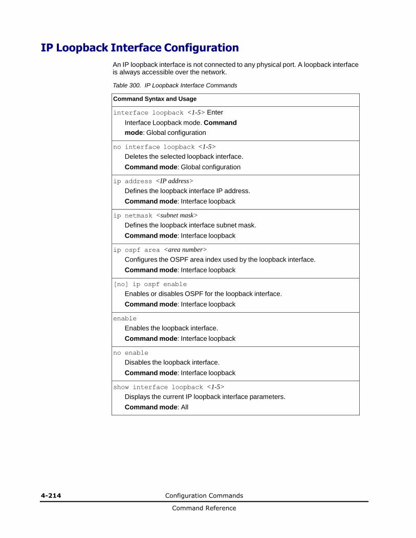
4-214 Configuration Commands
Command Reference
IP Loopback Interface Configuration
An IP loopback interface is not connected to any physical port. A loopback interface is always accessible over the network.
Table 300. IP Loopback Interface Commands
Command Syntax and Usage
interface loopback <1-5> Enter
Interface Loopback mode. Command
mode: Global configuration
no interface loopback <1-5>
Deletes the selected loopback interface.
Command mode: Global configuration
ip address <IP address>
Defines the loopback interface IP address.
Command mode: Interface loopback
ip netmask <subnet mask>
Defines the loopback interface subnet mask.
Command mode: Interface loopback
ip ospf area <area number>
Configures the OSPF area index used by the loopback interface.
Command mode: Interface loopback
[no] ip ospf enable
Enables or disables OSPF for the loopback interface.
Command mode: Interface loopback
enable
Enables the loopback interface.
Command mode: Interface loopback
no enable
Disables the loopback interface.
Command mode: Interface loopback
show interface loopback <1-5>
Displays the current IP loopback interface parameters.
Command mode: All
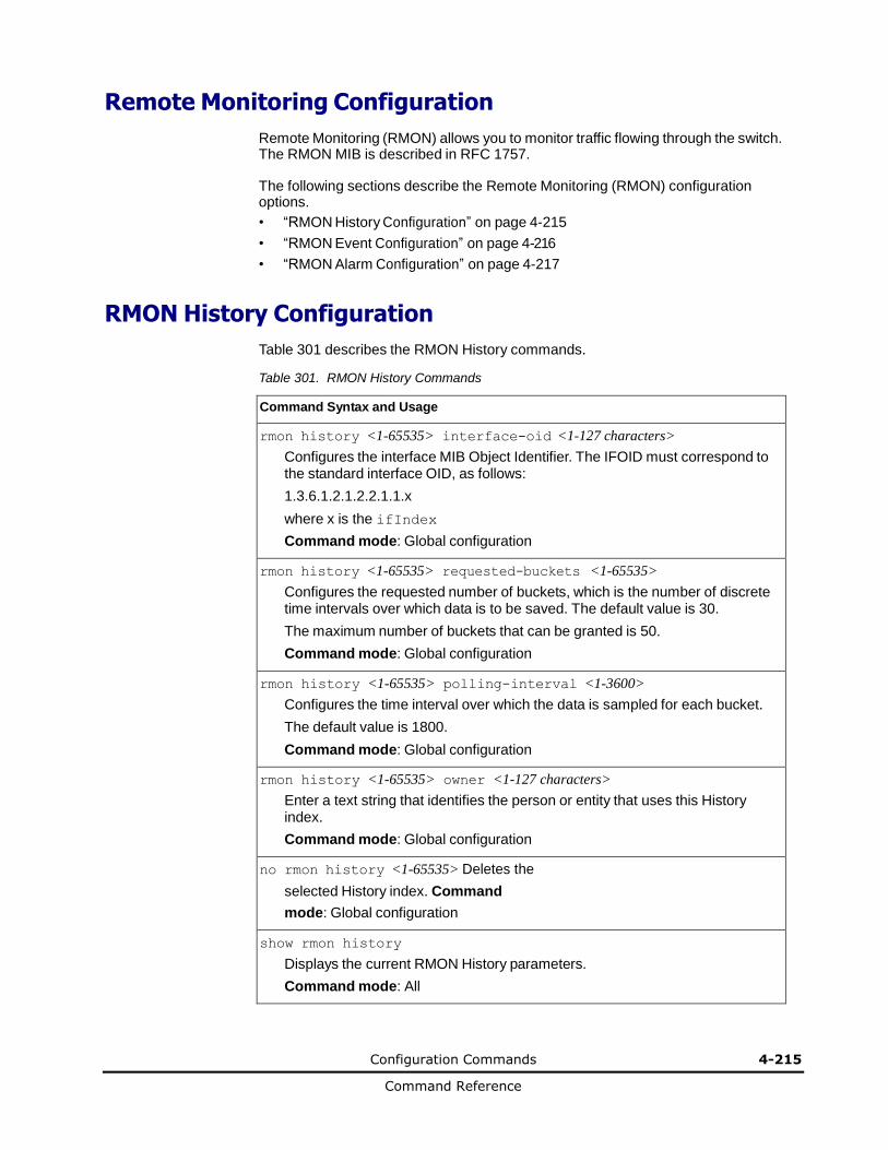
Configuration Commands 4-215
Command Reference
Remote Monitoring Configuration
Remote Monitoring (RMON) allows you to monitor traffic flowing through the switch. The RMON MIB is described in RFC 1757.
The following sections describe the Remote Monitoring (RMON) configuration options.
• “RMON History Configuration” on page 4-215
• “RMON Event Configuration” on page 4-216
• “RMON Alarm Configuration” on page 4-217
RMON History Configuration
Table 301 describes the RMON History commands.
Table 301. RMON History Commands
Command Syntax and Usage
rmon history <1-65535> interface-oid <1-127 characters>
Configures the interface MIB Object Identifier. The IFOID must correspond to the standard interface OID, as follows:
1.3.6.1.2.1.2.2.1.1.x
where x is the ifIndex
Command mode: Global configuration
rmon history <1-65535> requested-buckets <1-65535>
Configures the requested number of buckets, which is the number of discrete time intervals over which data is to be saved. The default value is 30.
The maximum number of buckets that can be granted is 50.
Command mode: Global configuration
rmon history <1-65535> polling-interval <1-3600>
Configures the time interval over which the data is sampled for each bucket.
The default value is 1800.
Command mode: Global configuration
rmon history <1-65535> owner <1-127 characters>
Enter a text string that identifies the person or entity that uses this History index.
Command mode: Global configuration
no rmon history <1-65535> Deletes the
selected History index. Command
mode: Global configuration
show rmon history
Displays the current RMON History parameters.
Command mode: All
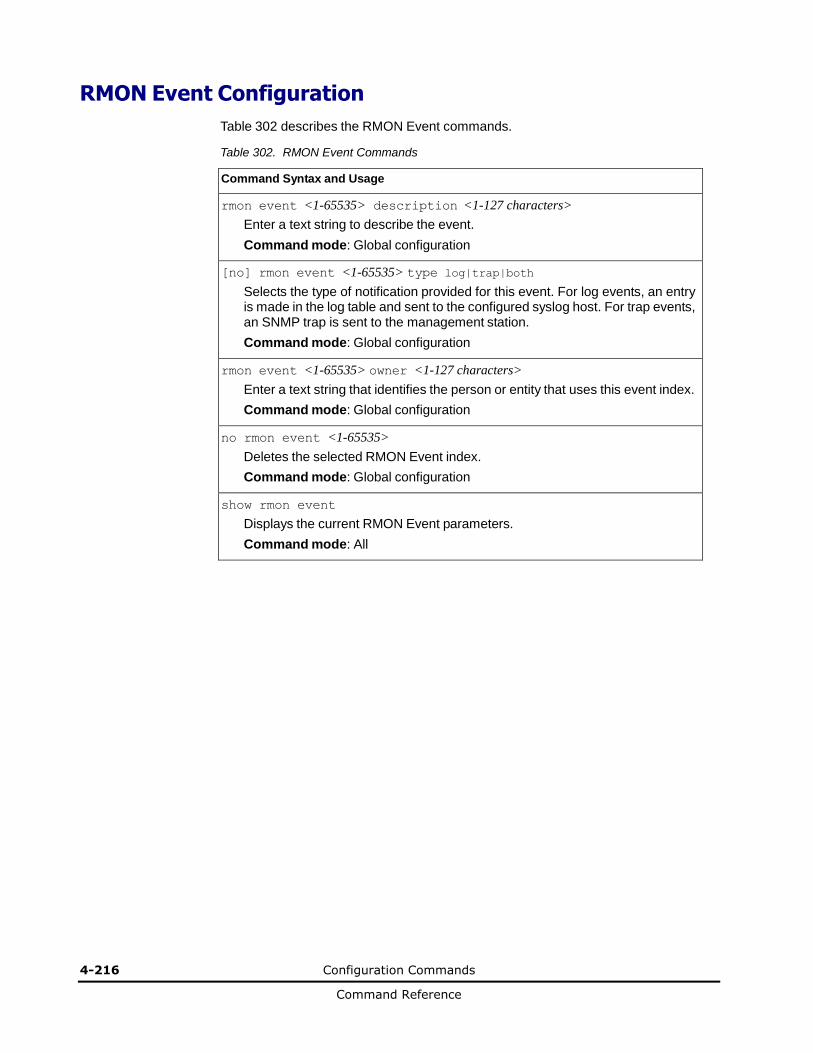
4-216 Configuration Commands
Command Reference
RMON Event Configuration
Table 302 describes the RMON Event commands.
Table 302. RMON Event Commands
Command Syntax and Usage
rmon event <1-65535> description <1-127 characters>
Enter a text string to describe the event.
Command mode: Global configuration
[no] rmon event <1-65535> type log|trap|both
Selects the type of notification provided for this event. For log events, an entry is made in the log table and sent to the configured syslog host. For trap events, an SNMP trap is sent to the management station.
Command mode: Global configuration
rmon event <1-65535> owner <1-127 characters>
Enter a text string that identifies the person or entity that uses this event index.
Command mode: Global configuration
no rmon event <1-65535>
Deletes the selected RMON Event index.
Command mode: Global configuration
show rmon event
Displays the current RMON Event parameters.
Command mode: All
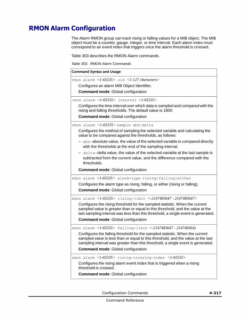
Configuration Commands 4-217
Command Reference
RMON Alarm Configuration
The Alarm RMON group can track rising or falling values for a MIB object. The MIB object must be a counter, gauge, integer, or time interval. Each alarm index must correspond to an event index that triggers once the alarm threshold is crossed.
Table 303 describes the RMON Alarm commands.
Table 303. RMON Alarm Commands
Command Syntax and Usage
rmon alarm <1-65535> oid <1-127 characters>
Configures an alarm MIB Object Identifier.
Command mode: Global configuration
rmon alarm <1-65535> interval <1-65535>
Configures the time interval over which data is sampled and compared with the rising and falling thresholds. The default value is 1800.
Command mode: Global configuration
rmon alarm <1-65535> sample abs|delta
Configures the method of sampling the selected variable and calculating the value to be compared against the thresholds, as follows:
– abs—absolute value, the value of the selected variable is compared directly
with the thresholds at the end of the sampling interval.
– delta—delta value, the value of the selected variable at the last sample is
subtracted from the current value, and the difference compared with the
thresholds.
Command mode: Global configuration
rmon alarm <1-65535> alarm-type rising|falling|either
Configures the alarm type as rising, falling, or either (rising or falling).
Command mode: Global configuration
rmon alarm <1-65535> rising-limit <-2147483647 - 2147483647>
Configures the rising threshold for the sampled statistic. When the current sampled value is greater than or equal to this threshold, and the value at the last sampling interval was less than this threshold, a single event is generated.
Command mode: Global configuration
rmon alarm <1-65535> falling-limit <-2147483647 - 214748364)
Configures the falling threshold for the sampled statistic. When the current sampled value is less than or equal to this threshold, and the value at the last sampling interval was greater than this threshold, a single event is generated.
Command mode: Global configuration
rmon alarm <1-65535> rising-crossing-index <1-65535>
Configures the rising alarm event index that is triggered when a rising threshold is crossed.
Command mode: Global configuration
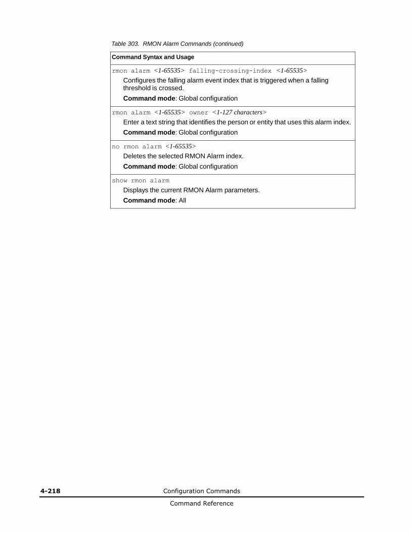
4-218 Configuration Commands
Command Reference
Table 303. RMON Alarm Commands (continued)
Command Syntax and Usage
rmon alarm <1-65535> falling-crossing-index <1-65535>
Configures the falling alarm event index that is triggered when a falling threshold is crossed.
Command mode: Global configuration
rmon alarm <1-65535> owner <1-127 characters>
Enter a text string that identifies the person or entity that uses this alarm index.
Command mode: Global configuration
no rmon alarm <1-65535>
Deletes the selected RMON Alarm index.
Command mode: Global configuration
show rmon alarm
Displays the current RMON Alarm parameters.
Command mode: All
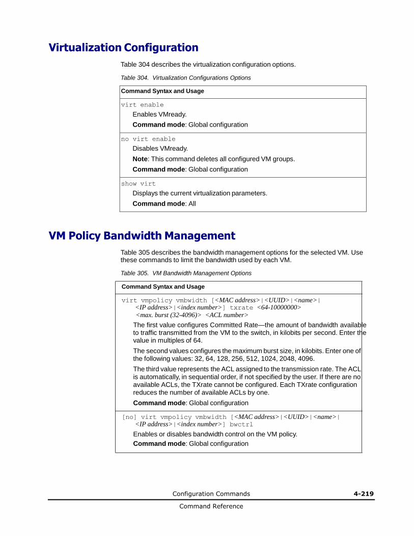
Configuration Commands 4-219
Command Reference
Virtualization Configuration
Table 304 describes the virtualization configuration options.
Table 304. Virtualization Configurations Options
Command Syntax and Usage
virt enable
Enables VMready.
Command mode: Global configuration
no virt enable
Disables VMready.
Note: This command deletes all configured VM groups.
Command mode: Global configuration
show virt
Displays the current virtualization parameters.
Command mode: All
VM Policy Bandwidth Management
Table 305 describes the bandwidth management options for the selected VM. Use these commands to limit the bandwidth used by each VM.
Table 305. VM Bandwidth Management Options
Command Syntax and Usage
virt vmpolicy vmbwidth [<MAC address>|<UUID>|<name>| <IP address>|<index number>] txrate <64-10000000> <max. burst (32-4096)> <ACL number>
The first value configures Committed Rate—the amount of bandwidth available to traffic transmitted from the VM to the switch, in kilobits per second. Enter the value in multiples of 64.
The second values configures the maximum burst size, in kilobits. Enter one of the following values: 32, 64, 128, 256, 512, 1024, 2048, 4096.
The third value represents the ACL assigned to the transmission rate. The ACL is automatically, in sequential order, if not specified by the user. If there are no available ACLs, the TXrate cannot be configured. Each TXrate configuration reduces the number of available ACLs by one.
Command mode: Global configuration
[no] virt vmpolicy vmbwidth [<MAC address>|<UUID>|<name>| <IP address>|<index number>] bwctrl
Enables or disables bandwidth control on the VM policy.
Command mode: Global configuration
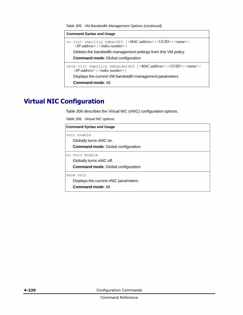
4-220 Configuration Commands
Command Reference
Table 305. VM Bandwidth Management Options (continued)
Command Syntax and Usage
no virt vmpolicy vmbwidth [<MAC address>|<UUID>|<name>| <IP address>|<index number>]
Deletes the bandwidth management settings from this VM policy.
Command mode: Global configuration
show virt vmpolicy vmbandwidth [<MAC address>|<UUID>|<name>| <IP address>|<index number>]
Displays the current VM bandwidth management parameters.
Command mode: All
Virtual NIC Configuration
Table 306 describes the Virtual NIC (vNIC) configuration options.
Table 306. Virtual NIC options
Command Syntax and Usage
vnic enable
Globally turns vNIC on.
Command mode: Global configuration
no vnic enable
Globally turns vNIC off.
Command mode: Global configuration
show vnic
Displays the current vNIC parameters.
Command mode: All
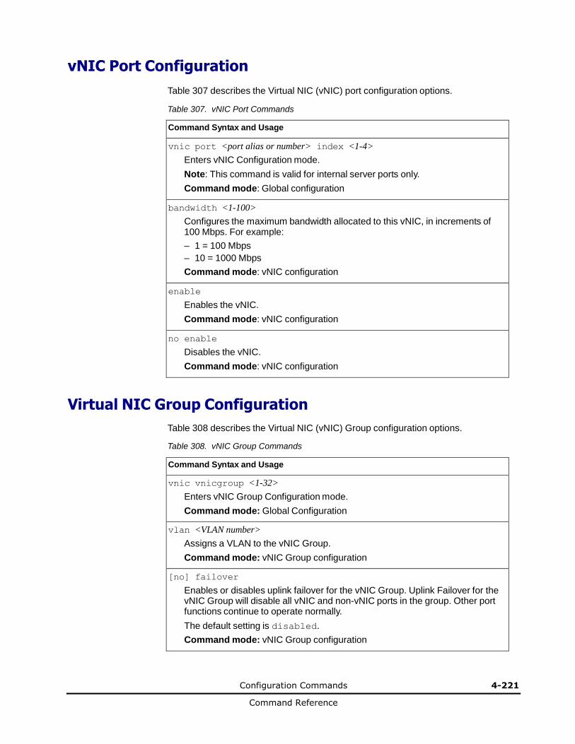
Configuration Commands 4-221
Command Reference
vNIC Port Configuration Table 307 describes the Virtual NIC (vNIC) port configuration options.
Table 307. vNIC Port Commands
Command Syntax and Usage
vnic port <port alias or number> index <1-4>
Enters vNIC Configuration mode.
Note: This command is valid for internal server ports only.
Command mode: Global configuration
bandwidth <1-100>
Configures the maximum bandwidth allocated to this vNIC, in increments of 100 Mbps. For example:
– 1 = 100 Mbps
– 10 = 1000 Mbps
Command mode: vNIC configuration
enable
Enables the vNIC.
Command mode: vNIC configuration
no enable
Disables the vNIC.
Command mode: vNIC configuration
Virtual NIC Group Configuration
Table 308 describes the Virtual NIC (vNIC) Group configuration options.
Table 308. vNIC Group Commands
Command Syntax and Usage
vnic vnicgroup <1-32>
Enters vNIC Group Configuration mode.
Command mode: Global Configuration
vlan <VLAN number>
Assigns a VLAN to the vNIC Group.
Command mode: vNIC Group configuration
[no] failover
Enables or disables uplink failover for the vNIC Group. Uplink Failover for the vNIC Group will disable all vNIC and non-vNIC ports in the group. Other port functions continue to operate normally.
The default setting is disabled.
Command mode: vNIC Group configuration
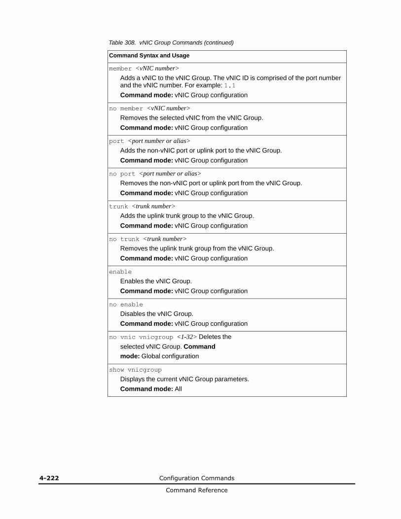
4-222 Configuration Commands
Command Reference
Table 308. vNIC Group Commands (continued)
Command Syntax and Usage
member <vNIC number>
Adds a vNIC to the vNIC Group. The vNIC ID is comprised of the port number and the vNIC number. For example: 1.1
Command mode: vNIC Group configuration
no member <vNIC number>
Removes the selected vNIC from the vNIC Group.
Command mode: vNIC Group configuration
port <port number or alias>
Adds the non-vNIC port or uplink port to the vNIC Group.
Command mode: vNIC Group configuration
no port <port number or alias>
Removes the non-vNIC port or uplink port from the vNIC Group.
Command mode: vNIC Group configuration
trunk <trunk number>
Adds the uplink trunk group to the vNIC Group.
Command mode: vNIC Group configuration
no trunk <trunk number>
Removes the uplink trunk group from the vNIC Group.
Command mode: vNIC Group configuration
enable
Enables the vNIC Group.
Command mode: vNIC Group configuration
no enable
Disables the vNIC Group.
Command mode: vNIC Group configuration
no vnic vnicgroup <1-32> Deletes the
selected vNIC Group. Command
mode: Global configuration
show vnicgroup
Displays the current vNIC Group parameters.
Command mode: All

Configuration Commands 4-223
Command Reference
VM Group Configuration
Table 309 describes the VM group configuration options.A VM group is a collection of members, such as VMs, ports, or trunk groups. Members of a VM group share certain properties, including VLAN membership, ACLs (VMAP), and VM profiles.
Table 309. VM Group Commands
Command Syntax and Usage
virt vmgroup <1-4096> cpu
Enables or disables sending unregistered IPMC to CPU.
Command mode: Global configuration
virt vmgroup <1-4096> flood
Enables or disables flooding unregistered IPMC.
Command mode: Global configuration
virt vmgroup <1-4096> optflood
Enables or disables optimized flooding.
Command mode: Global configuration
virt vmgroup <1-4096> vlan <VLAN number>
Assigns a VLAN to this VM group. If you do not assign a VLAN to the VM group, the switch automatically assigns an unused VLAN when adding a port or a VM to the VM Group.
Note: If you add a VM profile to this group, the group will use the VLAN assigned to the profile.
Command mode: Global configuration
[no] virt vmgroup <1-4096> vmap <VMAP number> intports|extports
Assigns the selected VLAN Map to this group. You can choose to limit operation of the VLAN Map to internal ports only or external ports only. If you do not select a port type, the VMAP is applied to the entire VM Group.
For more information about configuring VLAN Maps, see “VMAP Configuration” on page 4-69.
Command mode: Global configuration
[no] virt vmgroup <1-4096> tag
Enables or disables VLAN tagging on ports in this VM group.
Command mode: Global configuration
virt vmgroup <1-4096> vm [<MAC address>|<UUID>|<name>| <IP address>| <index number>]
Adds a VM to the VM group. Enter a unique identifier to select a VM. The UUID and name parameters apply only if Virtual Center information is configured (virt vmware vcspec). The VM index number is found in the VM information dump (show virt vm).
Note: If the VM is connected to a port that is contained within the VM group, do not add the VM to the VM group.
Command mode: Global configuration
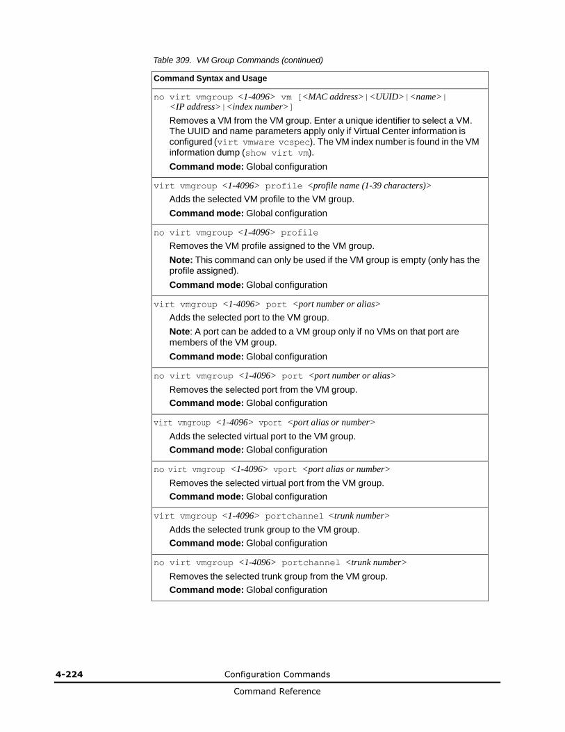
4-224 Configuration Commands
Command Reference
Table 309. VM Group Commands (continued)
Command Syntax and Usage
no virt vmgroup <1-4096> vm [<MAC address>|<UUID>|<name>| <IP address>|<index number>]
Removes a VM from the VM group. Enter a unique identifier to select a VM. The UUID and name parameters apply only if Virtual Center information is configured (virt vmware vcspec). The VM index number is found in the VM information dump (show virt vm).
Command mode: Global configuration
virt vmgroup <1-4096> profile <profile name (1-39 characters)>
Adds the selected VM profile to the VM group.
Command mode: Global configuration
no virt vmgroup <1-4096> profile
Removes the VM profile assigned to the VM group.
Note: This command can only be used if the VM group is empty (only has the profile assigned).
Command mode: Global configuration
virt vmgroup <1-4096> port <port number or alias>
Adds the selected port to the VM group.
Note: A port can be added to a VM group only if no VMs on that port are members of the VM group.
Command mode: Global configuration
no virt vmgroup <1-4096> port <port number or alias>
Removes the selected port from the VM group.
Command mode: Global configuration
virt vmgroup <1-4096> vport <port alias or number>
Adds the selected virtual port to the VM group.
Command mode: Global configuration
no virt vmgroup <1-4096> vport <port alias or number>
Removes the selected virtual port from the VM group.
Command mode: Global configuration
virt vmgroup <1-4096> portchannel <trunk number>
Adds the selected trunk group to the VM group.
Command mode: Global configuration
no virt vmgroup <1-4096> portchannel <trunk number>
Removes the selected trunk group from the VM group.
Command mode: Global configuration
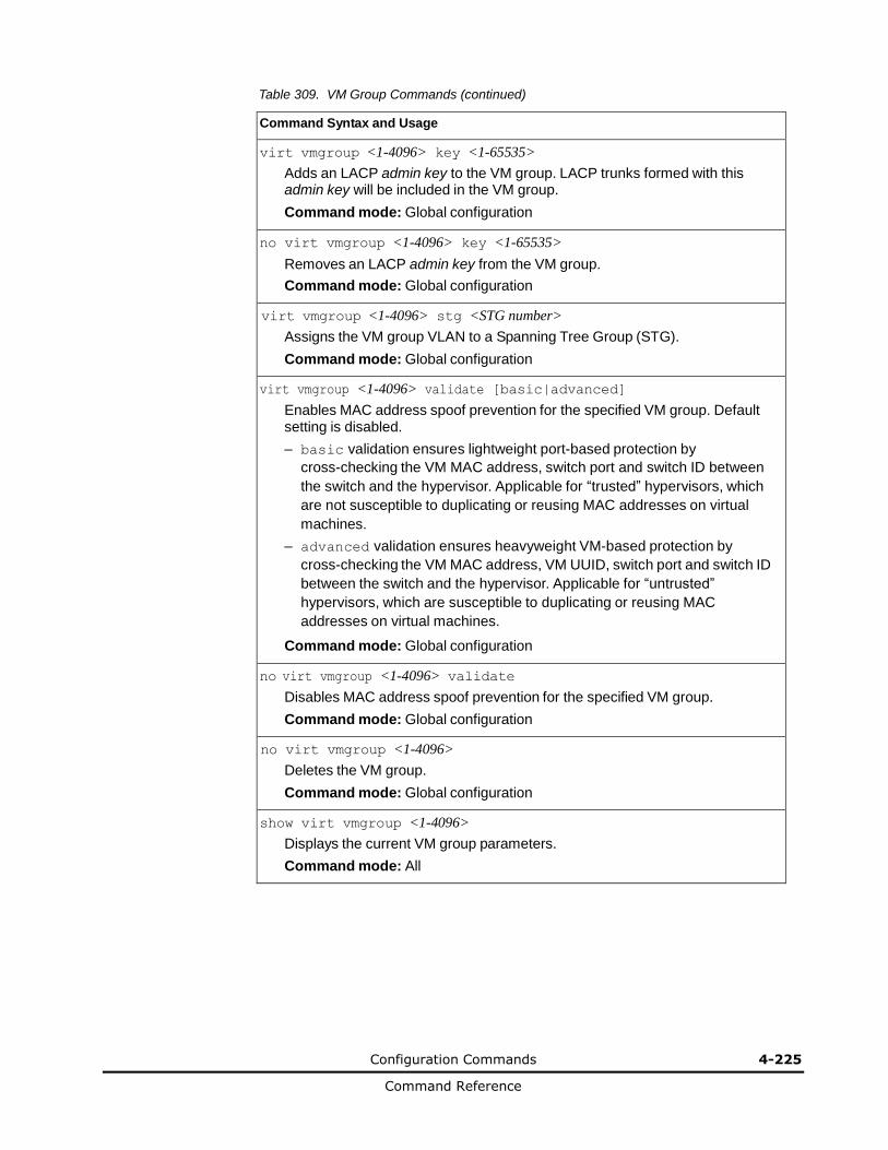
Configuration Commands 4-225
Command Reference
Table 309. VM Group Commands (continued)
Command Syntax and Usage
virt vmgroup <1-4096> key <1-65535>
Adds an LACP admin key to the VM group. LACP trunks formed with this admin key will be included in the VM group.
Command mode: Global configuration
no virt vmgroup <1-4096> key <1-65535>
Removes an LACP admin key from the VM group.
Command mode: Global configuration
virt vmgroup <1-4096> stg <STG number>
Assigns the VM group VLAN to a Spanning Tree Group (STG).
Command mode: Global configuration
virt vmgroup <1-4096> validate [basic|advanced]
Enables MAC address spoof prevention for the specified VM group. Default setting is disabled.
– basic validation ensures lightweight port-based protection by
cross-checking the VM MAC address, switch port and switch ID between
the switch and the hypervisor. Applicable for “trusted” hypervisors, which
are not susceptible to duplicating or reusing MAC addresses on virtual
machines.
– advanced validation ensures heavyweight VM-based protection by
cross-checking the VM MAC address, VM UUID, switch port and switch ID
between the switch and the hypervisor. Applicable for “untrusted”
hypervisors, which are susceptible to duplicating or reusing MAC
addresses on virtual machines.
Command mode: Global configuration
no virt vmgroup <1-4096> validate
Disables MAC address spoof prevention for the specified VM group.
Command mode: Global configuration
no virt vmgroup <1-4096>
Deletes the VM group.
Command mode: Global configuration
show virt vmgroup <1-4096>
Displays the current VM group parameters.
Command mode: All

4-226 Configuration Commands
Command Reference
VM Check Configuration
Table 310 describes the VM Check validation options used for MAC address spoof prevention.
Table 310. VM Check Configuration Options
Command Syntax and Usage
virt vmcheck acls max <1-640>
Configures the maximum number of ACLs that can be set up for MAC address spoofing prevention in advanced validation mode. Default value is 50.
Command mode: Global configuration
no virt vmcheck acls
Disables ACL-based MAC address spoofing prevention in advanced validation mode.
Command mode: Global configuration
virt vmcheck action basic {link|log}
Sets up action taken when detecting MAC address spoofing in basic validation mode:
– link registers a syslog entry and disables the corresponding switch port
– log registers a syslog entry
Default setting is link.
Command mode: Global configuration
virt vmcheck action advanced {acl|link|log}
Sets up action taken when detecting MAC address spoofing in advanced validation mode:
– acl registers a syslog entry and installs an ACL to drop traffic incoming on
the corresponding switch port originating from the spoofed MAC address
– link registers a syslog entry and disables the corresponding switch port
– log registers a syslog entry
Default setting is acl.
Command mode: Global configuration
[no] virt vmcheck trust <ports>
Enables or disables trusted ports for VM communication. By default, all ports are disabled.
Command mode: Global configuration
show virt vmcheck
Displays the current VM Check settings. See page 4-226 for sample output.
Command mode: Global configuration
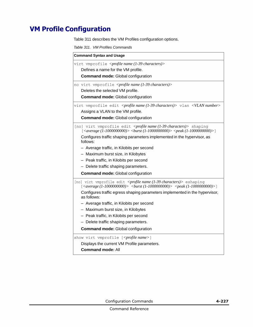
Configuration Commands 4-227
Command Reference
VM Profile Configuration
Table 311 describes the VM Profiles configuration options.
Table 311. VM Profiles Commands
Command Syntax and Usage
virt vmprofile <profile name (1-39 characters)>
Defines a name for the VM profile.
Command mode: Global configuration
no virt vmprofile <profile name (1-39 characters)>
Deletes the selected VM profile.
Command mode: Global configuration
virt vmprofile edit <profile name (1-39 characters)> vlan <VLAN number>
Assigns a VLAN to the VM profile.
Command mode: Global configuration
[no] virt vmprofile edit <profile name (1-39 characters)> shaping [<average (1-1000000000)> <burst (1-1000000000)> <peak (1-1000000000)>]
Configures traffic shaping parameters implemented in the hypervisor, as follows:
– Average traffic, in Kilobits per second
– Maximum burst size, in Kilobytes
– Peak traffic, in Kilobits per second
– Delete traffic shaping parameters.
Command mode: Global configuration
[no] virt vmprofile edit <profile name (1-39 characters)> eshaping [<average (1-1000000000)> <burst (1-1000000000)> <peak (1-1000000000)>]
Configures traffic egress shaping parameters implemented in the hypervisor, as follows:
– Average traffic, in Kilobits per second
– Maximum burst size, in Kilobytes
– Peak traffic, in Kilobits per second
– Delete traffic shaping parameters.
Command mode: Global configuration
show virt vmprofile [<profile name>]
Displays the current VM Profile parameters.
Command mode: All
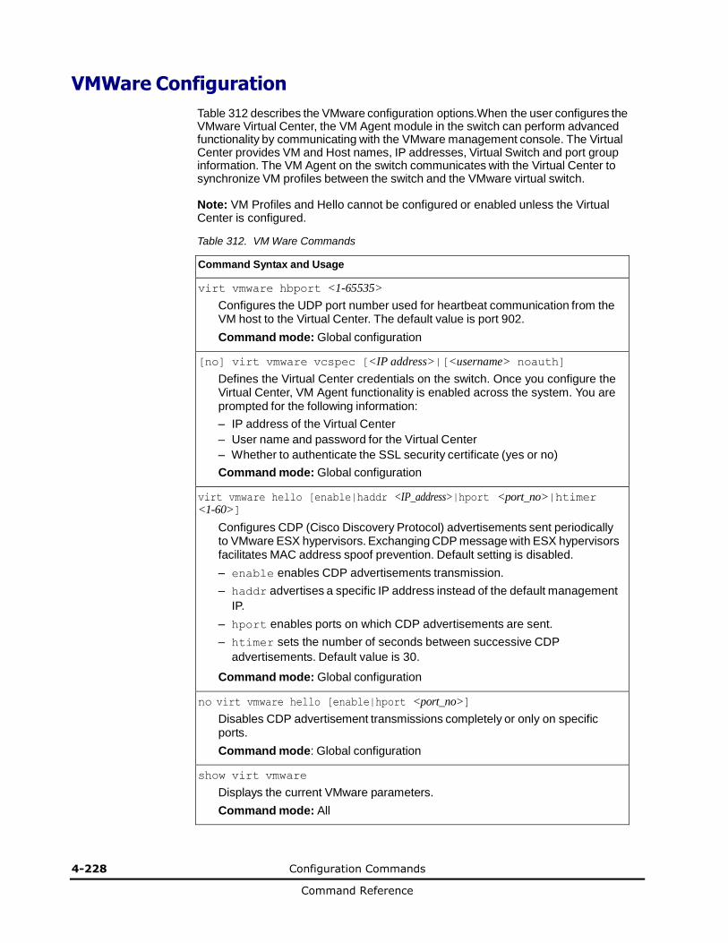
4-228 Configuration Commands
Command Reference
VMWare Configuration
Table 312 describes the VMware configuration options.When the user configures the VMware Virtual Center, the VM Agent module in the switch can perform advanced functionality by communicating with the VMware management console. The Virtual Center provides VM and Host names, IP addresses, Virtual Switch and port group information. The VM Agent on the switch communicates with the Virtual Center to synchronize VM profiles between the switch and the VMware virtual switch.
Note: VM Profiles and Hello cannot be configured or enabled unless the Virtual Center is configured.
Table 312. VM Ware Commands
Command Syntax and Usage
virt vmware hbport <1-65535>
Configures the UDP port number used for heartbeat communication from the VM host to the Virtual Center. The default value is port 902.
Command mode: Global configuration
[no] virt vmware vcspec [<IP address>|[<username> noauth]
Defines the Virtual Center credentials on the switch. Once you configure the Virtual Center, VM Agent functionality is enabled across the system. You are prompted for the following information:
– IP address of the Virtual Center
– User name and password for the Virtual Center
– Whether to authenticate the SSL security certificate (yes or no)
Command mode: Global configuration
virt vmware hello [enable|haddr <IP_address>|hport <port_no>|htimer <1-60>]
Configures CDP (Cisco Discovery Protocol) advertisements sent periodically to VMware ESX hypervisors. Exchanging CDP message with ESX hypervisors facilitates MAC address spoof prevention. Default setting is disabled.
– enable enables CDP advertisements transmission.
– haddr advertises a specific IP address instead of the default management
IP.
– hport enables ports on which CDP advertisements are sent.
– htimer sets the number of seconds between successive CDP
advertisements. Default value is 30.
Command mode: Global configuration
no virt vmware hello [enable|hport <port_no>]
Disables CDP advertisement transmissions completely or only on specific ports.
Command mode: Global configuration
show virt vmware
Displays the current VMware parameters.
Command mode: All
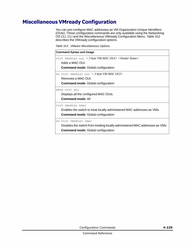
Configuration Commands 4-229
Command Reference
Miscellaneous VMready Configuration
You can pre-configure MAC addresses as VM Organization Unique Identifiers (OUIs). These configuration commands are only available using the Networking OS CLI, CLI and the Miscellaneous VMready Configuration Menu. Table 312 describes the VMready configuration options.
Table 313. VMware Miscellaneous Options
Command Syntax and Usage
virt vmrmisc oui < 3 byte VM MAC OUI> <Vendor Name>
Adds a MAC OUI.
Command mode: Global configuration
no virt vmrmisc oui < 3 byte VM MAC OUI>
Removes a MAC OUI.
Command mode: Global configuration
show virt oui
Displays all the configured MAC OUIs.
Command mode: All
virt vmrmisc lmac
Enables the switch to treat locally administered MAC addresses as VMs.
Command mode: Global configuration
no virt vmrmisc lmac
Disables the switch from treating locally administered MAC addresses as VMs.
Command mode: Global configuration
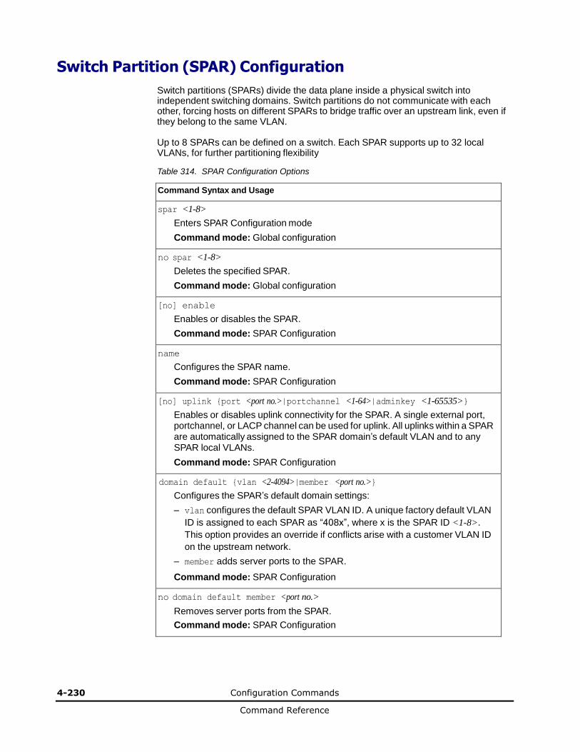
4-230 Configuration Commands
Command Reference
Switch Partition (SPAR) Configuration
Switch partitions (SPARs) divide the data plane inside a physical switch into independent switching domains. Switch partitions do not communicate with each other, forcing hosts on different SPARs to bridge traffic over an upstream link, even if they belong to the same VLAN.
Up to 8 SPARs can be defined on a switch. Each SPAR supports up to 32 local VLANs, for further partitioning flexibility
Table 314. SPAR Configuration Options
Command Syntax and Usage
spar <1-8>
Enters SPAR Configuration mode
Command mode: Global configuration
no spar <1-8>
Deletes the specified SPAR.
Command mode: Global configuration
[no] enable
Enables or disables the SPAR.
Command mode: SPAR Configuration
name
Configures the SPAR name.
Command mode: SPAR Configuration
[no] uplink {port <port no.>|portchannel <1-64>|adminkey <1-65535>}
Enables or disables uplink connectivity for the SPAR. A single external port, portchannel, or LACP channel can be used for uplink. All uplinks within a SPAR are automatically assigned to the SPAR domain’s default VLAN and to any SPAR local VLANs.
Command mode: SPAR Configuration
domain default {vlan <2-4094>|member <port no.>}
Configures the SPAR’s default domain settings:
– vlan configures the default SPAR VLAN ID. A unique factory default VLAN
ID is assigned to each SPAR as “408x”, where x is the SPAR ID <1-8>.
This option provides an override if conflicts arise with a customer VLAN ID
on the upstream network.
– member adds server ports to the SPAR.
Command mode: SPAR Configuration
no domain default member <port no.>
Removes server ports from the SPAR.
Command mode: SPAR Configuration
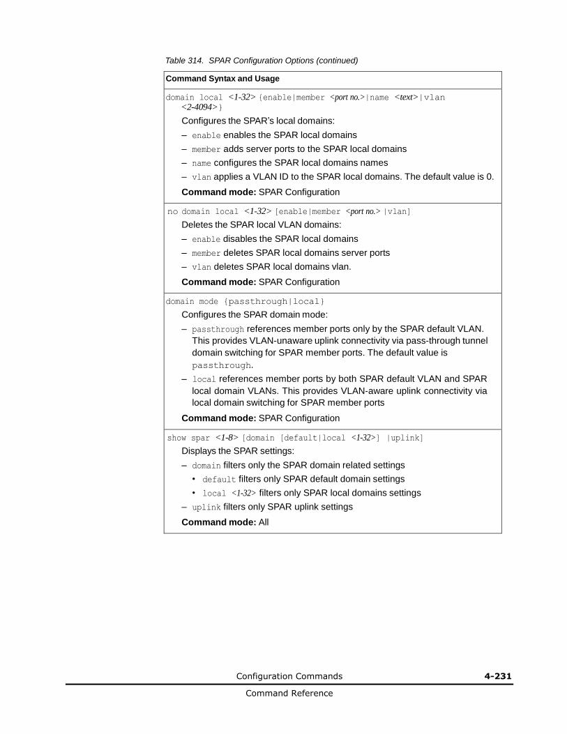
Configuration Commands 4-231
Command Reference
Table 314. SPAR Configuration Options (continued)
Command Syntax and Usage
domain local <1-32> {enable|member <port no.>|name <text>|vlan <2-4094>}
Configures the SPAR’s local domains:
– enable enables the SPAR local domains
– member adds server ports to the SPAR local domains
– name configures the SPAR local domains names
– vlan applies a VLAN ID to the SPAR local domains. The default value is 0.
Command mode: SPAR Configuration
no domain local <1-32> [enable|member <port no.> |vlan]
Deletes the SPAR local VLAN domains:
– enable disables the SPAR local domains
– member deletes SPAR local domains server ports
– vlan deletes SPAR local domains vlan.
Command mode: SPAR Configuration
domain mode {passthrough|local}
Configures the SPAR domain mode:
– passthrough references member ports only by the SPAR default VLAN.
This provides VLAN-unaware uplink connectivity via pass-through tunnel
domain switching for SPAR member ports. The default value is
passthrough.
– local references member ports by both SPAR default VLAN and SPAR
local domain VLANs. This provides VLAN-aware uplink connectivity via
local domain switching for SPAR member ports
Command mode: SPAR Configuration
show spar <1-8> [domain [default|local <1-32>] |uplink]
Displays the SPAR settings:
– domain filters only the SPAR domain related settings
• default filters only SPAR default domain settings
• local <1-32> filters only SPAR local domains settings
– uplink filters only SPAR uplink settings
Command mode: All
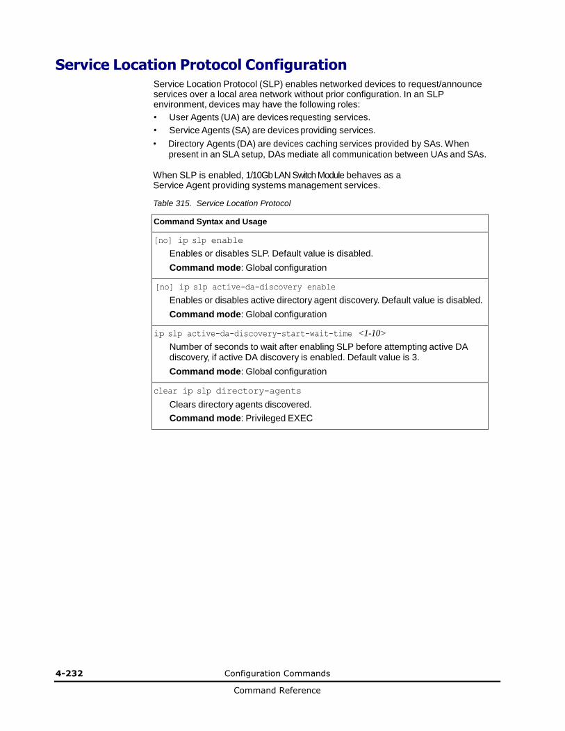
4-232 Configuration Commands
Command Reference
Service Location Protocol Configuration
Service Location Protocol (SLP) enables networked devices to request/announce services over a local area network without prior configuration. In an SLP environment, devices may have the following roles:
• User Agents (UA) are devices requesting services.
• Service Agents (SA) are devices providing services.
• Directory Agents (DA) are devices caching services provided by SAs. When present in an SLA setup, DAs mediate all communication between UAs and SAs.
When SLP is enabled, 1/10Gb LAN Switch Module behaves as a Service Agent providing systems management services.
Table 315. Service Location Protocol
Command Syntax and Usage
[no] ip slp enable
Enables or disables SLP. Default value is disabled.
Command mode: Global configuration
[no] ip slp active-da-discovery enable
Enables or disables active directory agent discovery. Default value is disabled.
Command mode: Global configuration
ip slp active-da-discovery-start-wait-time <1-10>
Number of seconds to wait after enabling SLP before attempting active DA discovery, if active DA discovery is enabled. Default value is 3.
Command mode: Global configuration
clear ip slp directory-agents
Clears directory agents discovered.
Command mode: Privileged EXEC

Configuration Commands 4-233
Command Reference
Configuration Dump
The dump program writes the current switch configuration to the terminal screen. To start the dump program, at the prompt, enter:
Router(config)# show running-config
The configuration is displayed with parameters that have been changed from the default values. The screen display can be captured, edited, and placed in a script file, which can be used to configure other switches through a Telnet connection. When using Telnet to configure a new switch, paste the configuration commands from the script file at the command line prompt of the switch. The active configuration can also be saved or loaded via FTP/TFTP, as described on page 4-233.
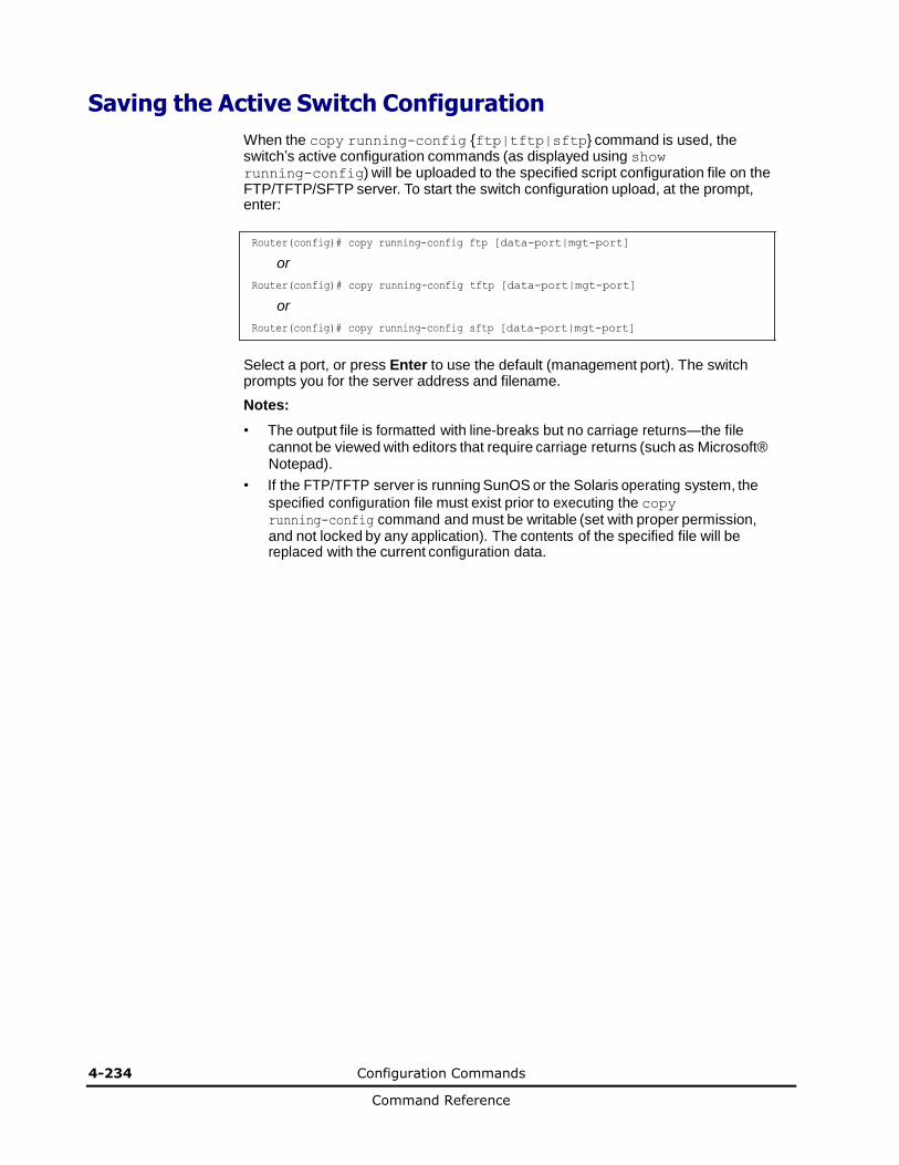
4-234 Configuration Commands
Command Reference
Saving the Active Switch Configuration
When the copy running-config {ftp|tftp|sftp} command is used, the switch’s active configuration commands (as displayed using show running-config) will be uploaded to the specified script configuration file on the FTP/TFTP/SFTP server. To start the switch configuration upload, at the prompt, enter:
Router(config)# copy running-config ftp [data-port|mgt-port]
or
Router(config)# copy running-config tftp [data-port|mgt-port]
or
Router(config)# copy running-config sftp [data-port|mgt-port]
Select a port, or press Enter to use the default (management port). The switch prompts you for the server address and filename.
Notes:
• The output file is formatted with line-breaks but no carriage returns—the file cannot be viewed with editors that require carriage returns (such as Microsoft® Notepad).
• If the FTP/TFTP server is running SunOS or the Solaris operating system, the
specified configuration file must exist prior to executing the copy running-config command and must be writable (set with proper permission, and not locked by any application). The contents of the specified file will be replaced with the current configuration data.
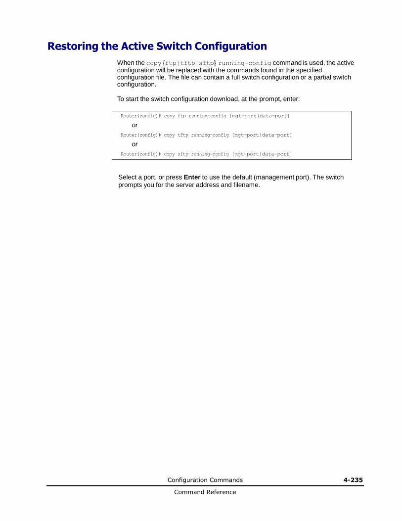
Configuration Commands 4-235
Command Reference
Restoring the Active Switch Configuration
When the copy {ftp|tftp|sftp} running-config command is used, the active configuration will be replaced with the commands found in the specified configuration file. The file can contain a full switch configuration or a partial switch configuration.
To start the switch configuration download, at the prompt, enter:
Router(config)# copy ftp running-config [mgt-port|data-port]
or
Router(config)# copy tftp running-config [mgt-port|data-port]
or
Router(config)# copy sftp running-config [mgt-port|data-port]
Select a port, or press Enter to use the default (management port). The switch prompts you for the server address and filename.


5
Maintenance Commands 5-1
Command Reference
Operations Commands
This chapter discusses the Operations Commands for 1/10Gb LAN Switch
Module.
Operations Commands
Operations-Level Port Commands
Operations-Level Port 802.1X Commands
Operations-Level VRRP Commands
Operations-Level BGP Commands
Protected Mode Options
VMware Operations
VMware Distributed Virtual Switch Operations
VMware Distributed Port Group Operations
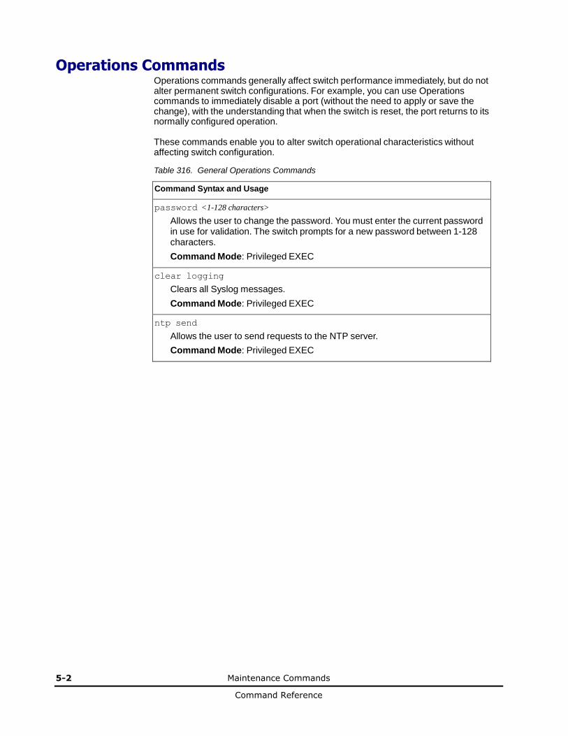
5-2 Maintenance Commands
Command Reference
Operations Commands Operations commands generally affect switch performance immediately, but do not alter permanent switch configurations. For example, you can use Operations commands to immediately disable a port (without the need to apply or save the change), with the understanding that when the switch is reset, the port returns to its normally configured operation.
These commands enable you to alter switch operational characteristics without affecting switch configuration.
Table 316. General Operations Commands
Command Syntax and Usage
password <1-128 characters>
Allows the user to change the password. You must enter the current password in use for validation. The switch prompts for a new password between 1-128 characters.
Command Mode: Privileged EXEC
clear logging
Clears all Syslog messages.
Command Mode: Privileged EXEC
ntp send
Allows the user to send requests to the NTP server.
Command Mode: Privileged EXEC

Maintenance Commands 5-3
Command Reference
Operations-Level Port Commands
Operations-level port options are used for temporarily disabling or enabling a port, and for re-setting the port.
Table 317. Port Operations Commands
Command Syntax and Usage
no interface port <port number or alias> shutdown
Temporarily enables the port. The port will be returned to its configured operation mode when the switch is reset.
Command Mode: Privileged EXEC
interface port <port number or alias> shutdown
Temporarily disables the port. The port will be returned to its configured operation mode when the switch is reset.
Command Mode: Privileged EXEC
[no] interface portchannel <1-52> shutdown
Temporarily enables or disables the specified port channel. The port channel will be returned to its configured operation mode when the switch is reset.
Command Mode: Privileged EXEC
[no] interface portchannel lacp <1-65535> shutdown
Temporarily enables or disables specified LACP trunk groups.
Command Mode: Privileged EXEC
show interface port <port number or alias> operation
Displays the port interface operational state.
Command Mode: Privileged EXEC
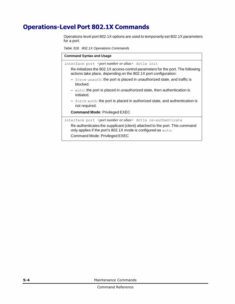
5-4 Maintenance Commands
Command Reference
Operations-Level Port 802.1X Commands
Operations-level port 802.1X options are used to temporarily set 802.1X parameters for a port.
Table 318. 802.1X Operations Commands
Command Syntax and Usage
interface port <port number or alias> dot1x init
Re-initializes the 802.1X access-control parameters for the port. The following actions take place, depending on the 802.1X port configuration:
– force unauth: the port is placed in unauthorized state, and traffic is
blocked.
– auto: the port is placed in unauthorized state, then authentication is
initiated.
– force auth: the port is placed in authorized state, and authentication is
not required.
Command Mode: Privileged EXEC
interface port <port number or alias> dot1x re-authenticate
Re-authenticates the supplicant (client) attached to the port. This command
only applies if the port’s 802.1X mode is configured as auto.
Command Mode: Privileged EXEC
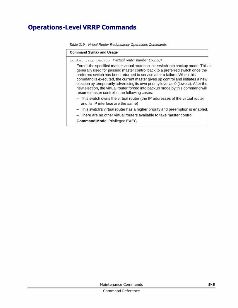
Maintenance Commands 5-5
Command Reference
Operations-Level VRRP Commands
Table 319. Virtual Router Redundancy Operations Commands
Command Syntax and Usage
router vrrp backup <virtual router number (1-255)>
Forces the specified master virtual router on this switch into backup mode. This is generally used for passing master control back to a preferred switch once the preferred switch has been returned to service after a failure. When this command is executed, the current master gives up control and initiates a new election by temporarily advertising its own priority level as 0 (lowest). After the new election, the virtual router forced into backup mode by this command will resume master control in the following cases:
– This switch owns the virtual router (the IP addresses of the virtual router
and its IP interface are the same)
– This switch’s virtual router has a higher priority and preemption is enabled.
– There are no other virtual routers available to take master control.
Command Mode: Privileged EXEC
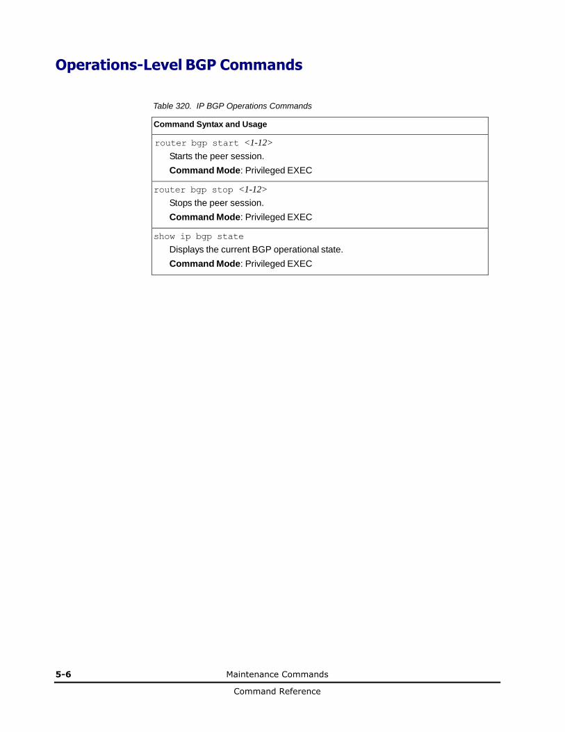
5-6 Maintenance Commands
Command Reference
Operations-Level BGP Commands
Table 320. IP BGP Operations Commands
Command Syntax and Usage
router bgp start <1-12>
Starts the peer session.
Command Mode: Privileged EXEC
router bgp stop <1-12>
Stops the peer session.
Command Mode: Privileged EXEC
show ip bgp state
Displays the current BGP operational state.
Command Mode: Privileged EXEC
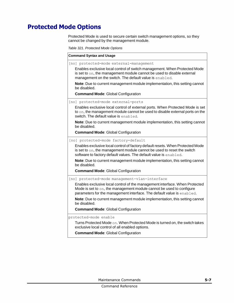
Maintenance Commands 5-7
Command Reference
Protected Mode Options
Protected Mode is used to secure certain switch management options, so they cannot be changed by the management module.
Table 321. Protected Mode Options
Command Syntax and Usage
[no] protected-mode external-management
Enables exclusive local control of switch management. When Protected Mode is set to on, the management module cannot be used to disable external
management on the switch. The default value is enabled.
Note: Due to current management module implementation, this setting cannot be disabled.
Command Mode: Global Configuration
[no] protected-mode external-ports
Enables exclusive local control of external ports. When Protected Mode is set to on, the management module cannot be used to disable external ports on the
switch. The default value is enabled.
Note: Due to current management module implementation, this setting cannot be disabled.
Command Mode: Global Configuration
[no] protected-mode factory-default
Enables exclusive local control of factory default resets. When Protected Mode is set to on, the management module cannot be used to reset the switch
software to factory default values. The default value is enabled.
Note: Due to current management module implementation, this setting cannot be disabled.
Command Mode: Global Configuration
[no] protected-mode management-vlan-interface
Enables exclusive local control of the management interface. When Protected Mode is set to on, the management module cannot be used to configure
parameters for the management interface. The default value is enabled.
Note: Due to current management module implementation, this setting cannot be disabled.
Command Mode: Global Configuration
protected-mode enable
Turns Protected Mode on. When Protected Mode is turned on, the switch takes exclusive local control of all enabled options.
Command Mode: Global Configuration

5-8 Maintenance Commands
Command Reference
Table 321. Protected Mode Options (continued)
Command Syntax and Usage
no protected-mode enable
Turns Protected Mode off. When Protected Mode is turned off, the switch relinquishes exclusive local control of all enabled options.
Command Mode: Global Configuration
show protected-mode
Displays the current Protected Mode configuration.
Command Mode: Global Configuration
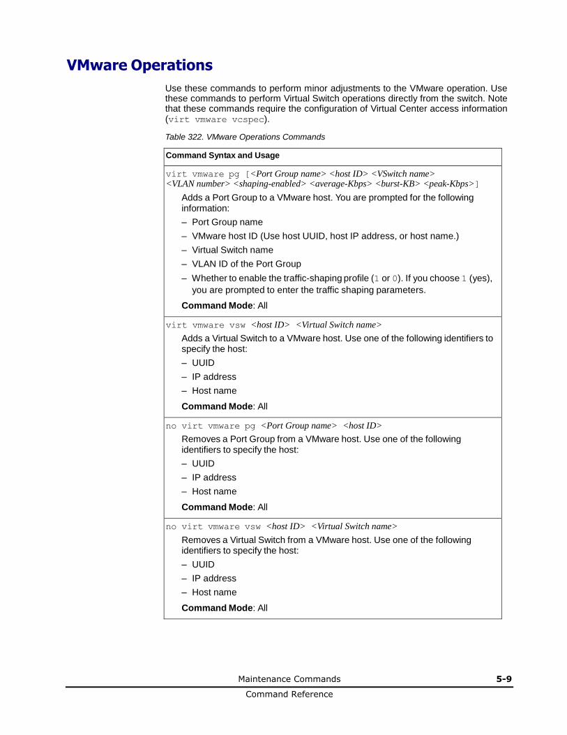
Maintenance Commands 5-9
Command Reference
VMware Operations
Use these commands to perform minor adjustments to the VMware operation. Use these commands to perform Virtual Switch operations directly from the switch. Note that these commands require the configuration of Virtual Center access information (virt vmware vcspec).
Table 322. VMware Operations Commands
Command Syntax and Usage
virt vmware pg [<Port Group name> <host ID> <VSwitch name> <VLAN number> <shaping-enabled> <average-Kbps> <burst-KB> <peak-Kbps>]
Adds a Port Group to a VMware host. You are prompted for the following information:
– Port Group name
– VMware host ID (Use host UUID, host IP address, or host name.)
– Virtual Switch name
– VLAN ID of the Port Group
– Whether to enable the traffic-shaping profile (1 or 0). If you choose 1 (yes),
you are prompted to enter the traffic shaping parameters.
Command Mode: All
virt vmware vsw <host ID> <Virtual Switch name>
Adds a Virtual Switch to a VMware host. Use one of the following identifiers to specify the host:
– UUID
– IP address
– Host name
Command Mode: All
no virt vmware pg <Port Group name> <host ID>
Removes a Port Group from a VMware host. Use one of the following identifiers to specify the host:
– UUID
– IP address
– Host name
Command Mode: All
no virt vmware vsw <host ID> <Virtual Switch name>
Removes a Virtual Switch from a VMware host. Use one of the following identifiers to specify the host:
– UUID
– IP address
– Host name
Command Mode: All
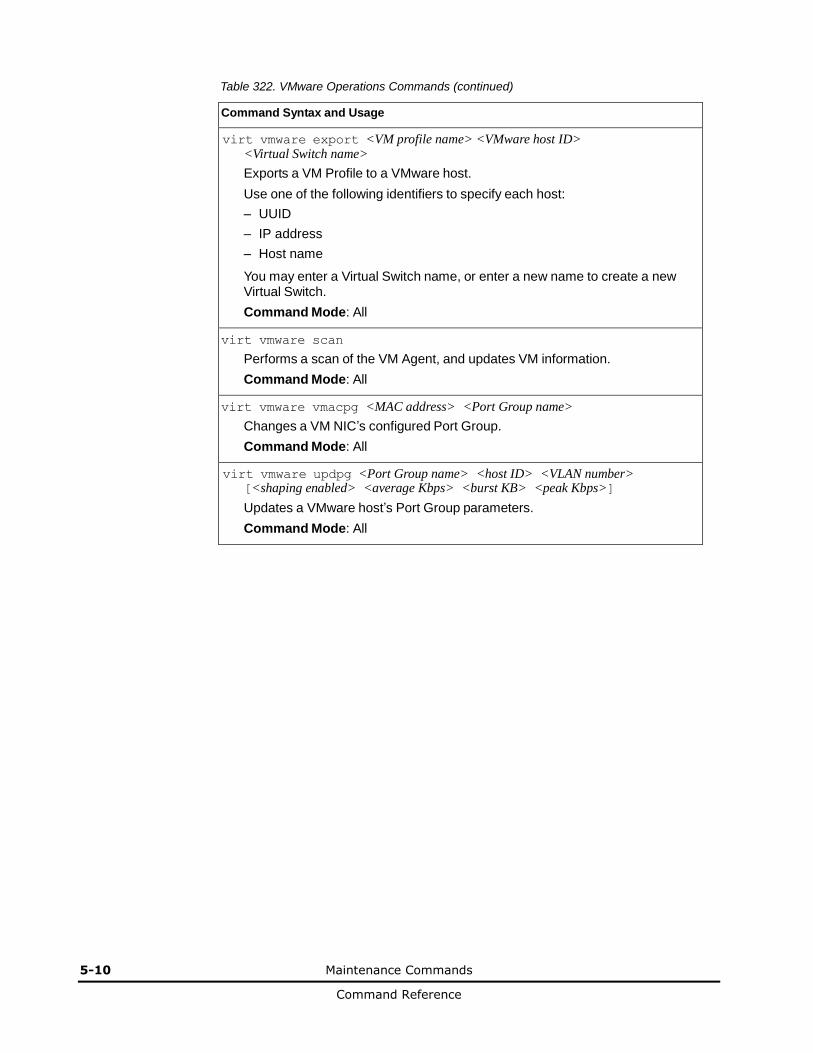
5-10 Maintenance Commands
Command Reference
Table 322. VMware Operations Commands (continued)
Command Syntax and Usage
virt vmware export <VM profile name> <VMware host ID> <Virtual Switch name>
Exports a VM Profile to a VMware host.
Use one of the following identifiers to specify each host:
– UUID
– IP address
– Host name
You may enter a Virtual Switch name, or enter a new name to create a new Virtual Switch.
Command Mode: All
virt vmware scan
Performs a scan of the VM Agent, and updates VM information.
Command Mode: All
virt vmware vmacpg <MAC address> <Port Group name>
Changes a VM NIC’s configured Port Group.
Command Mode: All
virt vmware updpg <Port Group name> <host ID> <VLAN number> [<shaping enabled> <average Kbps> <burst KB> <peak Kbps>]
Updates a VMware host’s Port Group parameters.
Command Mode: All
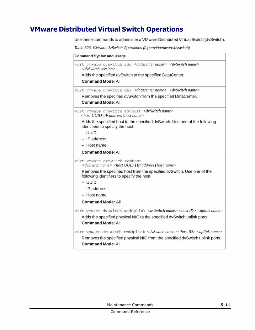
Maintenance Commands 5-11
Command Reference
VMware Distributed Virtual Switch Operations
Use these commands to administer a VMware Distributed Virtual Switch (dvSwitch).
Table 323. VMware dvSwitch Operations (/oper/virt/vmware/dvswitch)
Command Syntax and Usage
virt vmware dvswitch add <datacenter name> <dvSwitch name> <dvSwitch version>
Adds the specified dvSwitch to the specified DataCenter.
Command Mode: All
virt vmware dvswitch del <datacenter name> <dvSwitch name>
Removes the specified dvSwitch from the specified DataCenter.
Command Mode: All
virt vmware dvswitch addhost <dvSwitch name> <host UUID|IP address|host name>
Adds the specified host to the specified dvSwitch. Use one of the following identifiers to specify the host:
– UUID
– IP address
– Host name
Command Mode: All
virt vmware dvswitch remhost <dvSwitch name> <host UUID|IP address|host name>
Removes the specified host from the specified dvSwitch. Use one of the following identifiers to specify the host:
– UUID
– IP address
– Host name
Command Mode: All
virt vmware dvswitch addUplink <dvSwitch name> <host ID> <uplink name>
Adds the specified physical NIC to the specified dvSwitch uplink ports.
Command Mode: All
virt vmware dvswitch remUplink <dvSwitch name> <host ID> <uplink name>
Removes the specified physical NIC from the specified dvSwitch uplink ports.
Command Mode: All
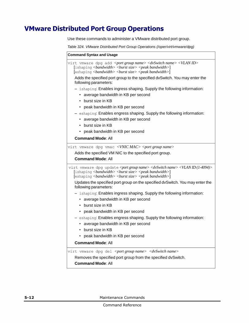
5-12 Maintenance Commands
Command Reference
VMware Distributed Port Group Operations
Use these commands to administer a VMware distributed port group.
Table 324. VMware Distributed Port Group Operations (/oper/virt/vmware/dpg)
Command Syntax and Usage
virt vmware dpg add <port group name> <dvSwitch name> <VLAN ID> [ishaping <bandwidth> <burst size> <peak bandwidth>] [eshaping <bandwidth> <burst size> <peak bandwidth>]
Adds the specified port group to the specified dvSwitch. You may enter the following parameters:
– ishaping: Enables ingress shaping. Supply the following information:
• average bandwidth in KB per second
• burst size in KB
• peak bandwidth in KB per second
– eshaping: Enables engress shaping. Supply the following information:
• average bandwidth in KB per second
• burst size in KB
• peak bandwidth in KB per second
Command Mode: All
virt vmware dpg vmac <VNIC MAC> <port group name>
Adds the specified VM NIC to the specified port group.
Command Mode: All
virt vmware dpg update <port group name> <dvSwitch name> <VLAN ID (1-4094)> [ishaping <bandwidth> <burst size> <peak bandwidth>] [eshaping <bandwidth> <burst size> <peak bandwidth>]
Updates the specified port group on the specified dvSwitch. You may enter the following parameters:
– ishaping: Enables ingress shaping. Supply the following information:
• average bandwidth in KB per second
• burst size in KB
• peak bandwidth in KB per second
– eshaping: Enables engress shaping. Supply the following information:
• average bandwidth in KB per second
• burst size in KB
• peak bandwidth in KB per second
Command Mode: All
virt vmware dpg del <port group name> <dvSwitch name>
Removes the specified port group from the specified dvSwitch.
Command Mode: All
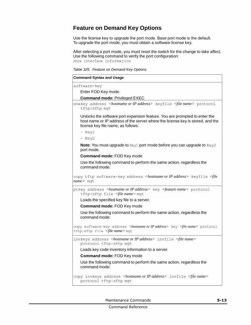
Maintenance Commands 5-13
Command Reference
Feature on Demand Key Options
Use the license key to upgrade the port mode. Base port mode is the default. To upgrade the port mode, you must obtain a software license key.
After selecting a port mode, you must reset the switch for the change to take affect. Use the following command to verify the port configuration: show interface information
Table 325. Feature on Demand Key Options
Command Syntax and Usage
software-key
Enter FOD Key mode.
Command mode: Privileged EXEC
enakey address <hostname or IP address> keyfile <file name> protocol tftp|sftp mgt
Unlocks the software port expansion feature. You are prompted to enter the host name or IP address of the server where the license key is stored, and the license key file name, as follows:
– Key1
– Key2
Note: You must upgrade to Key1 port mode before you can upgrade to Key2 port mode.
Command mode: FOD Key mode
Use the following command to perform the same action, regardless the command mode:
copy tftp software-key address <hostname or IP address> keyfile <file name> mgt
ptkey address <hostname or IP address> key <feature name> protocol tftp|sftp file <file name> mgt
Loads the specified key file to a server.
Command mode: FOD Key mode
Use the following command to perform the same action, regardless the command mode:
copy software-key address <hostname or IP address> key <file name> protocol
tftp|sftp file <file name> mgt
invkeys address <hostname or IP address> invfile <file name> protocol tftp|sftp mgt
Loads key code inventory information to a server.
Command mode: FOD Key mode
Use the following command to perform the same action, regardless the command mode:
copy invkeys address <hostname or IP address> invfile <file name>
protocol tftp|sftp mgt
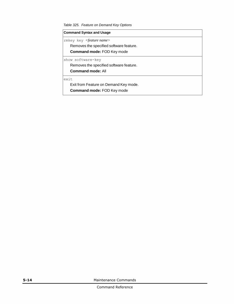
5-14 Maintenance Commands
Command Reference
Table 325. Feature on Demand Key Options
Command Syntax and Usage
rmkey key <feature name>
Removes the specified software feature.
Command mode: FOD Key mode
show software-key
Removes the specified software feature.
Command mode: All
exit
Exit from Feature on Demand Key mode.
Command mode: FOD Key mode
6
Maintenance Commands 6-1
Command Reference
Boot Options
The boot options are discussed in the following sections.
Boot Options
Updating the Switch Software Image
Selecting a Configuration Block
Resetting the Switch
Accessing the Networking OS CLI
Changing the Switch Profile
Using the Boot Management Menu
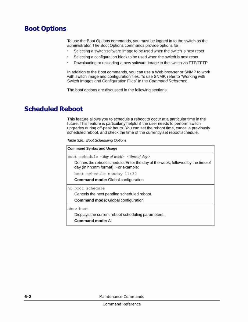
6-2 Maintenance Commands
Command Reference
Boot Options
To use the Boot Options commands, you must be logged in to the switch as the administrator. The Boot Options commands provide options for:
• Selecting a switch software image to be used when the switch is next reset
• Selecting a configuration block to be used when the switch is next reset
• Downloading or uploading a new software image to the switch via FTP/TFTP
In addition to the Boot commands, you can use a Web browser or SNMP to work with switch image and configuration files. To use SNMP, refer to “Working with Switch Images and Configuration Files” in the Command Reference. The boot options are discussed in the following sections.
Scheduled Reboot
This feature allows you to schedule a reboot to occur at a particular time in the future. This feature is particularly helpful if the user needs to perform switch upgrades during off-peak hours. You can set the reboot time, cancel a previously scheduled reboot, and check the time of the currently set reboot schedule.
Table 326. Boot Scheduling Options
Command Syntax and Usage
boot schedule <day of week> <time of day>
Defines the reboot schedule. Enter the day of the week, followed by the time of day (in hh:mm format). For example:
boot schedule monday 11:30
Command mode: Global configuration
no boot schedule
Cancels the next pending scheduled reboot.
Command mode: Global configuration
show boot
Displays the current reboot scheduling parameters.
Command mode: All

Maintenance Commands 6-3
Command Reference
Netboot Configuration
Netboot allows the switch to automatically download its configuration file over the network during switch reboot, and apply the new configuration. Upon reboot, the switch includes the following options in its DHCP requests:
• Option 66 (TFTP server address)
• Option 67 (file path)
If the DHCP server returns the information, the switch initiates a TFTP file transfer, and loads the configuration file into the active configuration block. As the switch boots up, it applies the new configuration file. Note that the option 66 TFTP server address must be specified in IP-address format (host name is not supported).
If DHCP is not enabled, or the DHCP server does not return the required information, the switch uses the manually-configured TFTP server address and file path.
Table 327. Netboot Options (/boot/netboot)
Command Syntax and Usage
boot netboot enable
Enables Netboot. When enabled, the switch boots into factory-default configuration, and attempts to download a new configuration file.
Command mode: Global configuration
no boot netboot enable
Disables Netboot.
Command mode: Global configuration
[no] boot netboot tftp <IP address>
Configures the IP address of the TFTP server used for manual configuration. This server is used if DHCP is not enabled, or if the DHCP server does not return the required information.
Command mode: Global configuration
[no] boot netboot cfgfile <1-31 characters>
Defines the file path for the configuration file on the TFTP server. For example:
/directory/sub/config.cfg
Command mode: Global configuration
show boot
Displays the current Netboot parameters.
Command mode: All
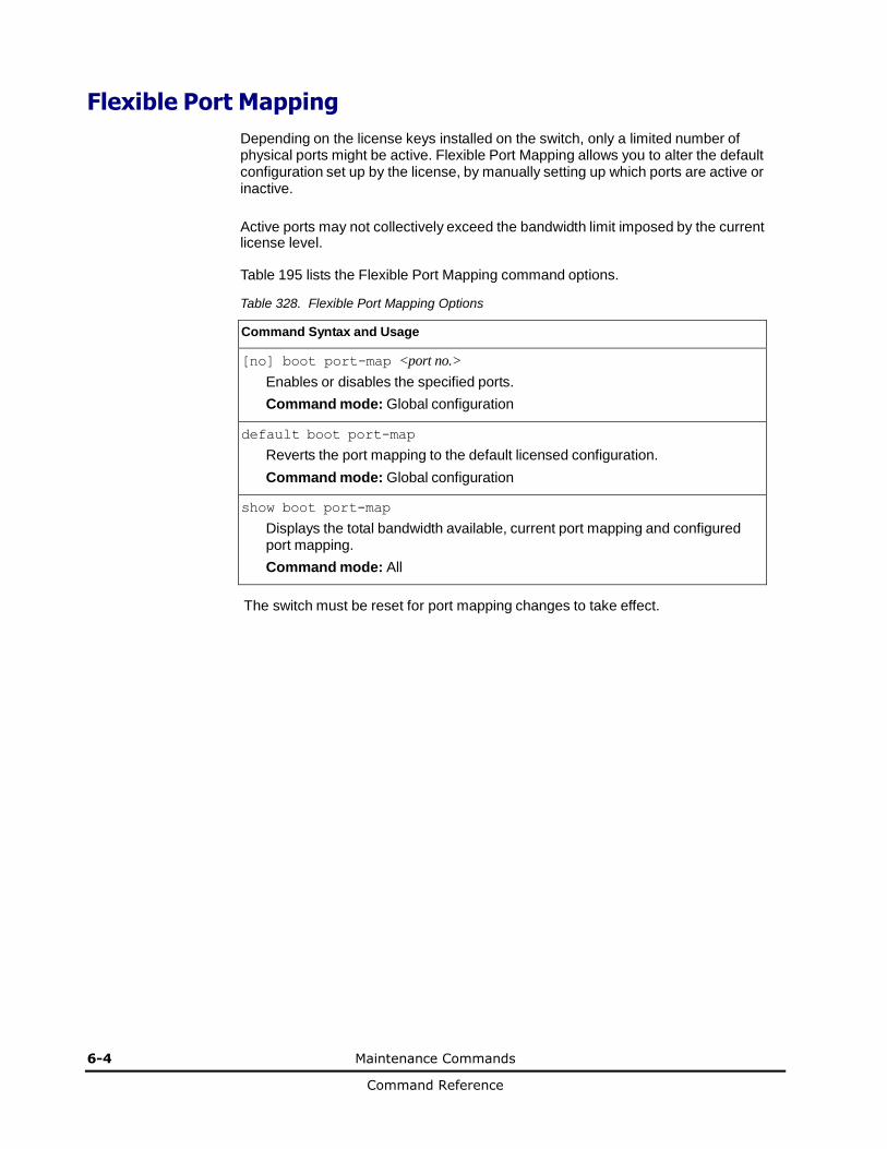
6-4 Maintenance Commands
Command Reference
Flexible Port Mapping
Depending on the license keys installed on the switch, only a limited number of physical ports might be active. Flexible Port Mapping allows you to alter the default configuration set up by the license, by manually setting up which ports are active or inactive.
Active ports may not collectively exceed the bandwidth limit imposed by the current license level.
Table 195 lists the Flexible Port Mapping command options.
Table 328. Flexible Port Mapping Options
Command Syntax and Usage
[no] boot port-map <port no.>
Enables or disables the specified ports.
Command mode: Global configuration
default boot port-map
Reverts the port mapping to the default licensed configuration.
Command mode: Global configuration
show boot port-map
Displays the total bandwidth available, current port mapping and configured port mapping.
Command mode: All
The switch must be reset for port mapping changes to take effect.
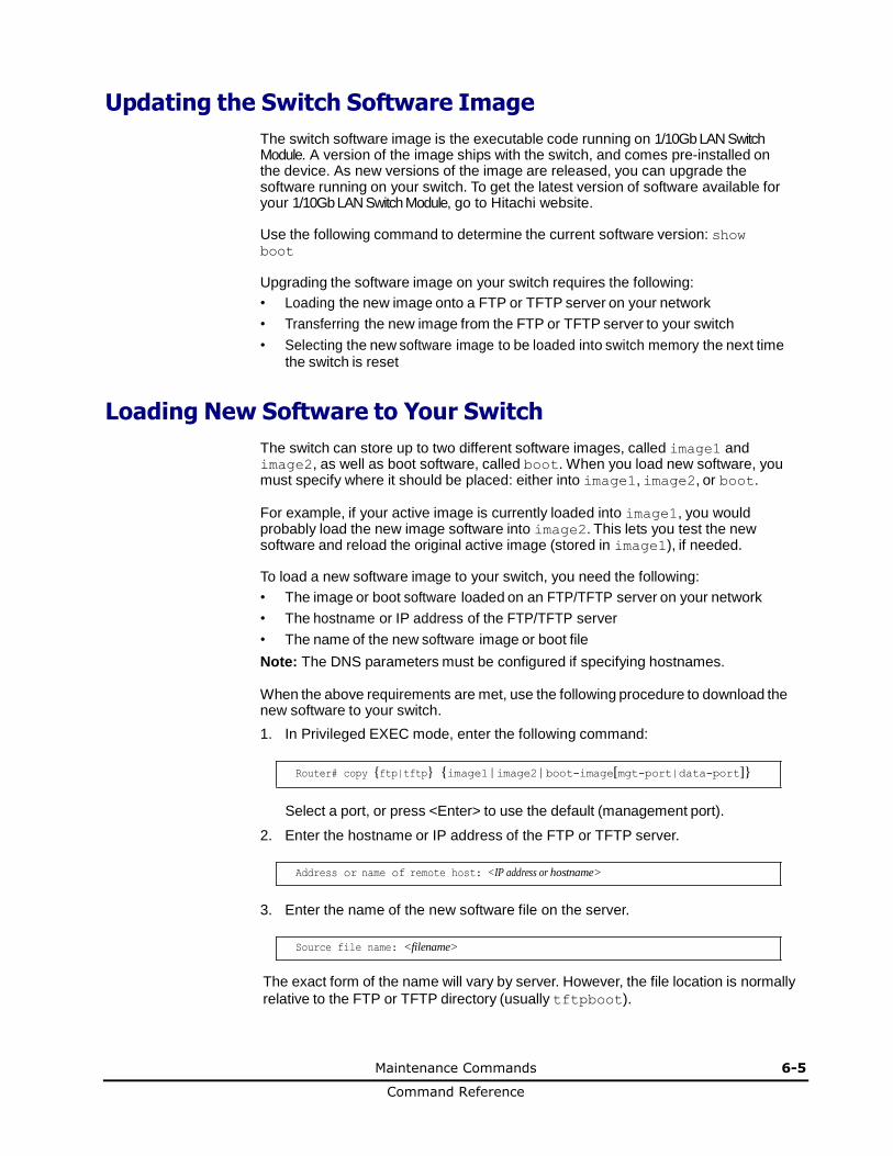
Maintenance Commands 6-5
Command Reference
Updating the Switch Software Image
The switch software image is the executable code running on 1/10Gb LAN Switch Module. A version of the image ships with the switch, and comes pre-installed on the device. As new versions of the image are released, you can upgrade the software running on your switch. To get the latest version of software available for your 1/10Gb LAN Switch Module, go to Hitachi website.
Use the following command to determine the current software version: show boot
Upgrading the software image on your switch requires the following:
• Loading the new image onto a FTP or TFTP server on your network
• Transferring the new image from the FTP or TFTP server to your switch
• Selecting the new software image to be loaded into switch memory the next time the switch is reset
Loading New Software to Your Switch
The switch can store up to two different software images, called image1 and image2, as well as boot software, called boot. When you load new software, you must specify where it should be placed: either into image1, image2, or boot.
For example, if your active image is currently loaded into image1, you would probably load the new image software into image2. This lets you test the new software and reload the original active image (stored in image1), if needed.
To load a new software image to your switch, you need the following:
• The image or boot software loaded on an FTP/TFTP server on your network
• The hostname or IP address of the FTP/TFTP server
• The name of the new software image or boot file
Note: The DNS parameters must be configured if specifying hostnames.
When the above requirements are met, use the following procedure to download the new software to your switch.
1. In Privileged EXEC mode, enter the following command:
Router# copy {ftp|tftp} {image1|image2|boot-image[mgt-port|data-port]}
Select a port, or press <Enter> to use the default (management port).
2. Enter the hostname or IP address of the FTP or TFTP server.
Address or name of remote host: <IP address or hostname>
3. Enter the name of the new software file on the server.
Source file name: <filename>
The exact form of the name will vary by server. However, the file location is normally
relative to the FTP or TFTP directory (usually tftpboot).
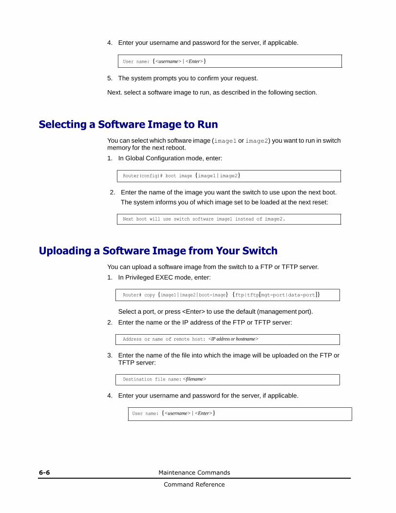
6-6 Maintenance Commands
Command Reference
4. Enter your username and password for the server, if applicable.
User name: {<username>|<Enter>}
5. The system prompts you to confirm your request.
Next. select a software image to run, as described in the following section.
Selecting a Software Image to Run
You can select which software image (image1 or image2) you want to run in switch memory for the next reboot.
1. In Global Configuration mode, enter:
Router(config)# boot image {image1|image2}
2. Enter the name of the image you want the switch to use upon the next boot.
The system informs you of which image set to be loaded at the next reset:
Next boot will use switch software image1 instead of image2.
Uploading a Software Image from Your Switch
You can upload a software image from the switch to a FTP or TFTP server.
1. In Privileged EXEC mode, enter:
Router# copy {image1|image2|boot-image} {ftp|tftp[mgt-port|data-port]}
Select a port, or press <Enter> to use the default (management port).
2. Enter the name or the IP address of the FTP or TFTP server:
Address or name of remote host: <IP address or hostname>
3. Enter the name of the file into which the image will be uploaded on the FTP or
TFTP server:
Destination file name: <filename>
4. Enter your username and password for the server, if applicable.
User name: {<username>|<Enter>}

Maintenance Commands 6-7
Command Reference
5. The system then requests confirmation of what you have entered. To have the file uploaded, enter Y.
image2 currently contains Software Version 6.5.0
that was downloaded at 0:23:39 Thu Jan 1, 2010
Upload will transfer image2 (2788535 bytes) to file "image1"
on FTP/TFTP server 1.90.90.95.
Confirm upload operation (y/n) ? y
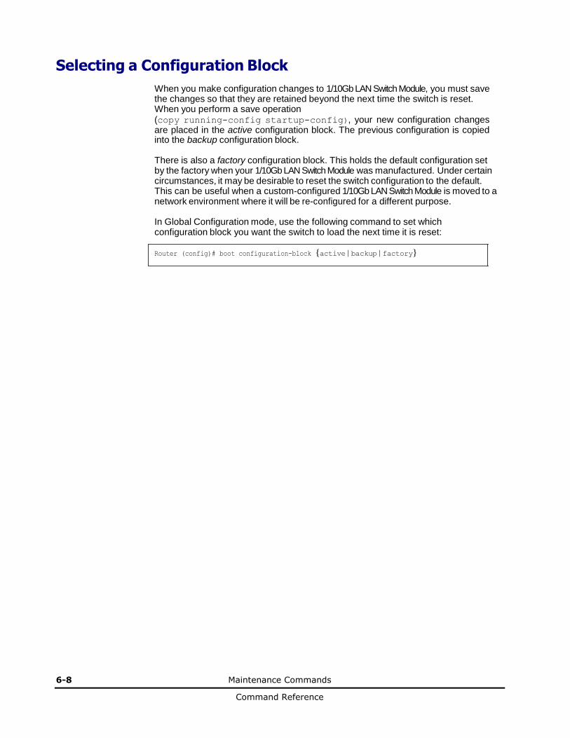
6-8 Maintenance Commands
Command Reference
Selecting a Configuration Block
When you make configuration changes to 1/10Gb LAN Switch Module, you must save the changes so that they are retained beyond the next time the switch is reset. When you perform a save operation (copy running-config startup-config), your new configuration changes are placed in the active configuration block. The previous configuration is copied into the backup configuration block.
There is also a factory configuration block. This holds the default configuration set by the factory when your 1/10Gb LAN Switch Module was manufactured. Under certain circumstances, it may be desirable to reset the switch configuration to the default. This can be useful when a custom-configured 1/10Gb LAN Switch Module is moved to a network environment where it will be re-configured for a different purpose.
In Global Configuration mode, use the following command to set which configuration block you want the switch to load the next time it is reset: Router (config)# boot configuration-block {active|backup|factory}

Maintenance Commands 6-9
Command Reference
Resetting the Switch
You can reset the switch to make your software image file and configuration block changes occur.
Note: Resetting the switch causes the Spanning Tree Group to restart. This process can be lengthy, depending on the topology of your network.
Enter the following command to reset (reload) the switch:
>> Router# reload
You are prompted to confirm your request.
Reset will use software "image2" and the active config block.
>> Note that this will RESTART the Spanning Tree,
>> which will likely cause an interruption in network service.
Confirm reload (y/n) ?
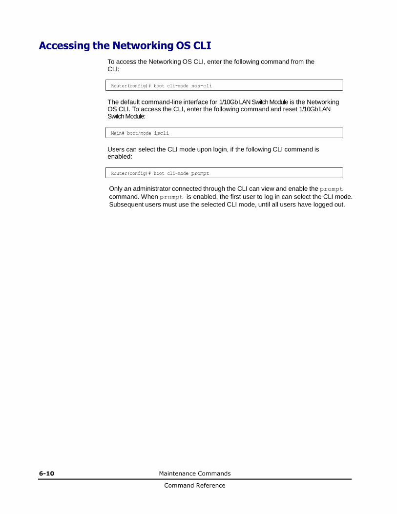
6-10 Maintenance Commands
Command Reference
Accessing the Networking OS CLI
To access the Networking OS CLI, enter the following command from the CLI:
Router(config)# boot cli-mode nos-cli
The default command-line interface for 1/10Gb LAN Switch Module is the Networking OS CLI. To access the CLI, enter the following command and reset 1/10Gb LAN Switch Module:
Main# boot/mode iscli
Users can select the CLI mode upon login, if the following CLI command is enabled:
Router(config)# boot cli-mode prompt
Only an administrator connected through the CLI can view and enable the prompt
command. When prompt is enabled, the first user to log in can select the CLI mode.
Subsequent users must use the selected CLI mode, until all users have logged out.
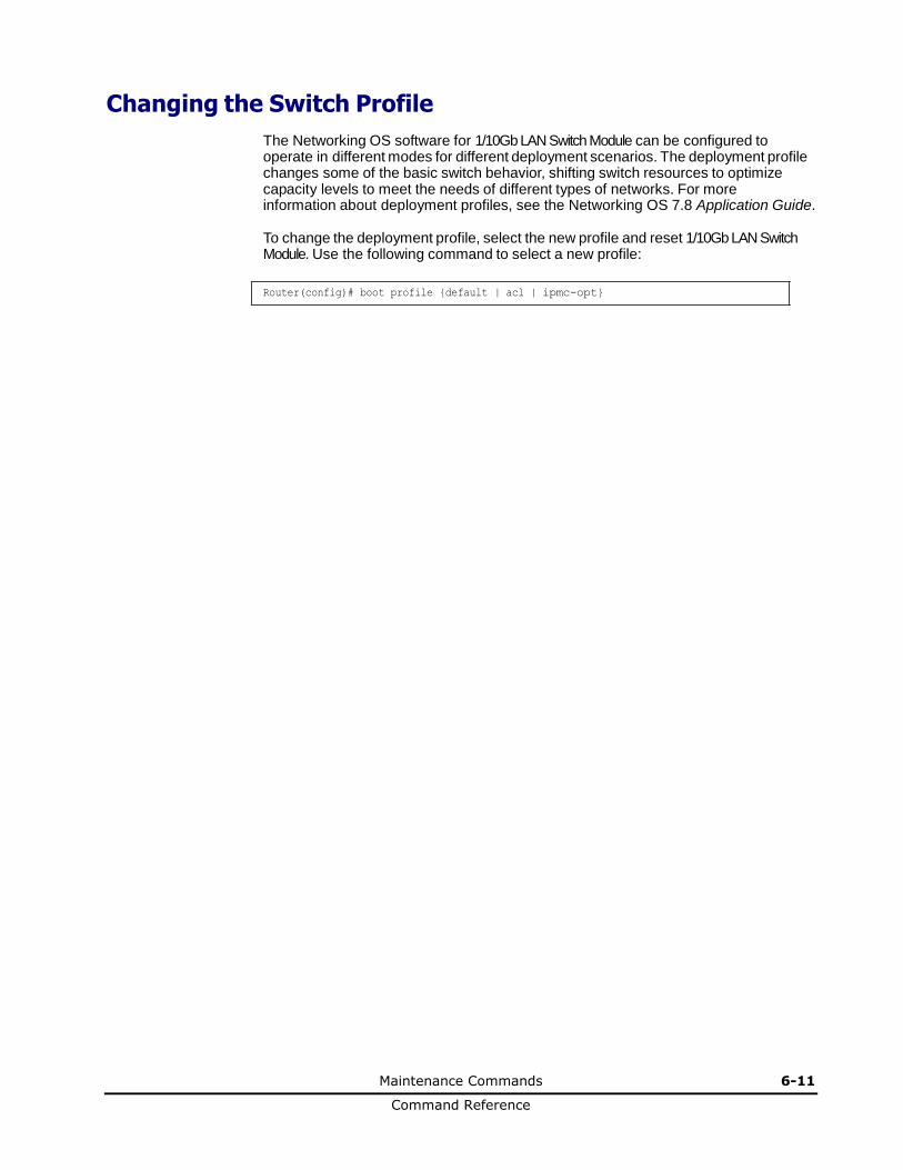
Maintenance Commands 6-11
Command Reference
Changing the Switch Profile
The Networking OS software for 1/10Gb LAN Switch Module can be configured to operate in different modes for different deployment scenarios. The deployment profile changes some of the basic switch behavior, shifting switch resources to optimize capacity levels to meet the needs of different types of networks. For more information about deployment profiles, see the Networking OS 7.8 Application Guide.
To change the deployment profile, select the new profile and reset 1/10Gb LAN Switch Module. Use the following command to select a new profile:
Router(config)# boot profile {default | acl | ipmc-opt}
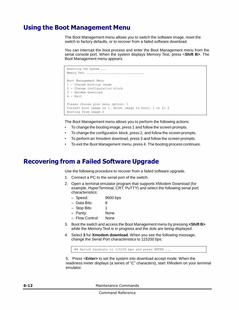
6-12 Maintenance Commands
Command Reference
Using the Boot Management Menu
The Boot Management menu allows you to switch the software image, reset the switch to factory defaults, or to recover from a failed software download.
You can interrupt the boot process and enter the Boot Management menu from the serial console port. When the system displays Memory Test, press <Shift B>. The Boot Management menu appears.
Resetting the System ...
Memory Test ................................
Boot Management Menu
1 - Change booting image
2 - Change configuration block
3 - Xmodem download
4 - Exit
Please choose your menu option: 1
Current boot image is 1. Enter image to boot: 1 or 2: 2
Booting from image 2
The Boot Management menu allows you to perform the following actions:
• To change the booting image, press 1 and follow the screen prompts.
• To change the configuration block, press 2, and follow the screen prompts.
• To perform an Xmodem download, press 3 and follow the screen prompts.
• To exit the Boot Management menu, press 4. The booting process continues.
Recovering from a Failed Software Upgrade
Use the following procedure to recover from a failed software upgrade.
1. Connect a PC to the serial port of the switch.
2. Open a terminal emulator program that supports XModem Download (for example, HyperTerminal, CRT, PuTTY) and select the following serial port characteristics:
– Speed: 9600 bps
– Data Bits: 8
– Stop Bits: 1
– Parity: None
– Flow Control: None
3. Boot the switch and access the Boot Management menu by pressing <Shift B> while the Memory Test is in progress and the dots are being displayed.
4. Select 3 for Xmodem download. When you see the following message, change the Serial Port characteristics to 115200 bps:
## Switch baudrate to 115200 bps and press ENTER ...
5. Press <Enter> to set the system into download accept mode. When the readiness meter displays (a series of “C” characters), start XModem on your terminal emulator.
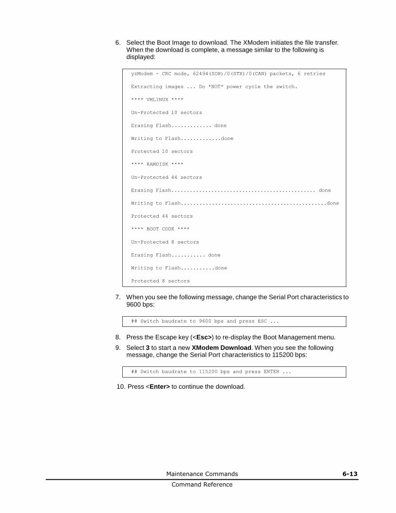
Maintenance Commands 6-13
Command Reference
6. Select the Boot Image to download. The XModem initiates the file transfer. When the download is complete, a message similar to the following is displayed:
yzModem - CRC mode, 62494(SOH)/0(STX)/0(CAN) packets, 6 retries
Extracting images ... Do *NOT* power cycle the switch.
**** VMLINUX ****
Un-Protected 10 sectors
Erasing Flash............. done
Writing to Flash.............done
Protected 10 sectors
**** RAMDISK ****
Un-Protected 44 sectors
Erasing Flash............................................... done
Writing to Flash...............................................done
Protected 44 sectors
**** BOOT CODE ****
Un-Protected 8 sectors
Erasing Flash........... done
Writing to Flash...........done
Protected 8 sectors
7. When you see the following message, change the Serial Port characteristics to
9600 bps:
## Switch baudrate to 9600 bps and press ESC ...
8. Press the Escape key (<Esc>) to re-display the Boot Management menu.
9. Select 3 to start a new XModem Download. When you see the following message, change the Serial Port characteristics to 115200 bps:
## Switch baudrate to 115200 bps and press ENTER ...
10. Press <Enter> to continue the download.
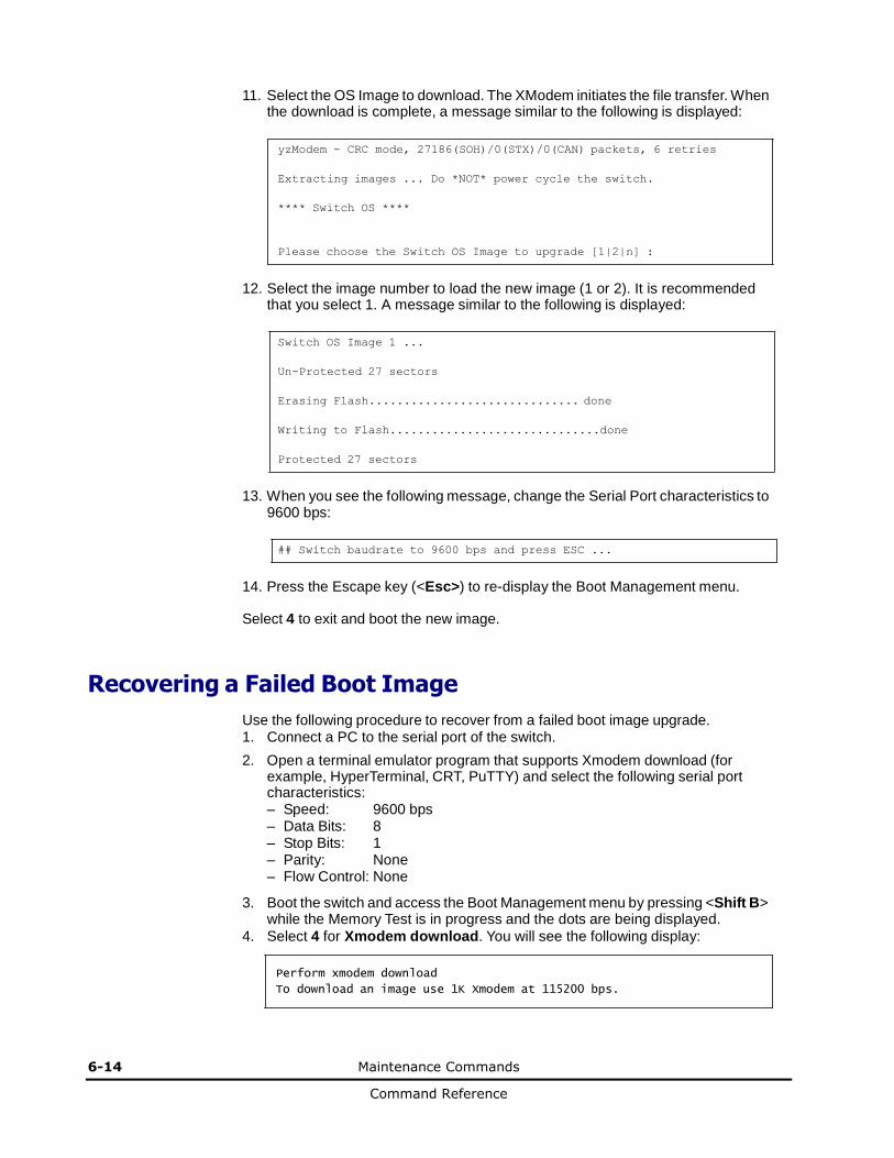
6-14 Maintenance Commands
Command Reference
11. Select the OS Image to download. The XModem initiates the file transfer. When the download is complete, a message similar to the following is displayed:
yzModem - CRC mode, 27186(SOH)/0(STX)/0(CAN) packets, 6 retries
Extracting images ... Do *NOT* power cycle the switch.
**** Switch OS ****
Please choose the Switch OS Image to upgrade [1|2|n] :
12. Select the image number to load the new image (1 or 2). It is recommended
that you select 1. A message similar to the following is displayed:
Switch OS Image 1 ...
Un-Protected 27 sectors
Erasing Flash.............................. done
Writing to Flash..............................done
Protected 27 sectors
13. When you see the following message, change the Serial Port characteristics to
9600 bps:
## Switch baudrate to 9600 bps and press ESC ...
14. Press the Escape key (<Esc>) to re-display the Boot Management menu.
Select 4 to exit and boot the new image.
Recovering a Failed Boot Image
Use the following procedure to recover from a failed boot image upgrade. 1. Connect a PC to the serial port of the switch.
2. Open a terminal emulator program that supports Xmodem download (for example, HyperTerminal, CRT, PuTTY) and select the following serial port characteristics: – Speed: 9600 bps – Data Bits: 8 – Stop Bits: 1 – Parity: None – Flow Control: None
3. Boot the switch and access the Boot Management menu by pressing <Shift B> while the Memory Test is in progress and the dots are being displayed.
4. Select 4 for Xmodem download. You will see the following display:
Perform xmodem download
To download an image use 1K Xmodem at 115200 bps.
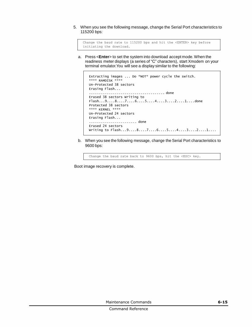
Maintenance Commands 6-15
Command Reference
5. When you see the following message, change the Serial Port characteristics to 115200 bps:
Change the baud rate to 115200 bps and hit the <ENTER> key before
initiating the download.
a. Press <Enter> to set the system into download accept mode. When the
readiness meter displays (a series of “C” characters), start Xmodem on your terminal emulator.You will see a display similar to the following:
Extracting images ... Do *NOT* power cycle the switch.
**** RAMDISK ****
Un-Protected 38 sectors
Erasing Flash...
...................................... done Erased 38 sectors Writing to
Flash...9....8....7....6....5....4....3....2....1....done
Protected 38 sectors
**** KERNEL ****
Un-Protected 24 sectors
Erasing Flash...
........................ done
Erased 24 sectors Writing to Flash...9....8....7....6....5....4....3....2....1....
b. When you see the following message, change the Serial Port characteristics to
9600 bps:
Change the baud rate back to 9600 bps, hit the <ESC> key.
Boot image recovery is complete.

6-16 Maintenance Commands
Command Reference
7
Maintenance Commands 7-1
Command Reference
Maintenance Commands
This chapter describes the maintenance commands that these are used to manage
dump information and forward database information. They also include debugging commands to help with troubleshooting.
Maintenance Commands
Forwarding Database Maintenance
Debugging Commands
ARP Cache Maintenance
IP Route Manipulation
LLDP Cache Manipulation
IGMP Group Maintenance
IGMP Multicast Routers Maintenance
IPv6 Neighbor Discovery Cache Manipulation
IPv6 Route Maintenance
Uuencode Flash Dump
TFTP, SFTP or FTP System Dump Put
Clearing Dump Information
Unscheduled System Dump
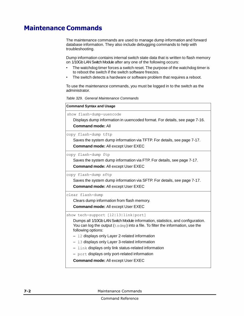
7-2 Maintenance Commands
Command Reference
Maintenance Commands
The maintenance commands are used to manage dump information and forward database information. They also include debugging commands to help with troubleshooting.
Dump information contains internal switch state data that is written to flash memory on 1/10Gb LAN Switch Module after any one of the following occurs:
• The watchdog timer forces a switch reset. The purpose of the watchdog timer is to reboot the switch if the switch software freezes.
• The switch detects a hardware or software problem that requires a reboot.
To use the maintenance commands, you must be logged in to the switch as the administrator.
Table 329. General Maintenance Commands
Command Syntax and Usage
show flash-dump-uuencode
Displays dump information in uuencoded format. For details, see page 7-16.
Command mode: All
copy flash-dump tftp
Saves the system dump information via TFTP. For details, see page 7-17.
Command mode: All except User EXEC
copy flash-dump ftp
Saves the system dump information via FTP. For details, see page 7-17.
Command mode: All except User EXEC
copy flash-dump sftp
Saves the system dump information via SFTP. For details, see page 7-17.
Command mode: All except User EXEC
clear flash-dump
Clears dump information from flash memory.
Command mode: All except User EXEC
show tech-support [l2|l3|link|port]
Dumps all 1/10Gb LAN Switch Module information, statistics, and configuration.
You can log the output (tsdmp) into a file. To filter the information, use the
following options:
– l2 displays only Layer 2-related information
– l3 displays only Layer 3-related information
– link displays only link status-related information
– port displays only port-related information
Command mode: All except User EXEC
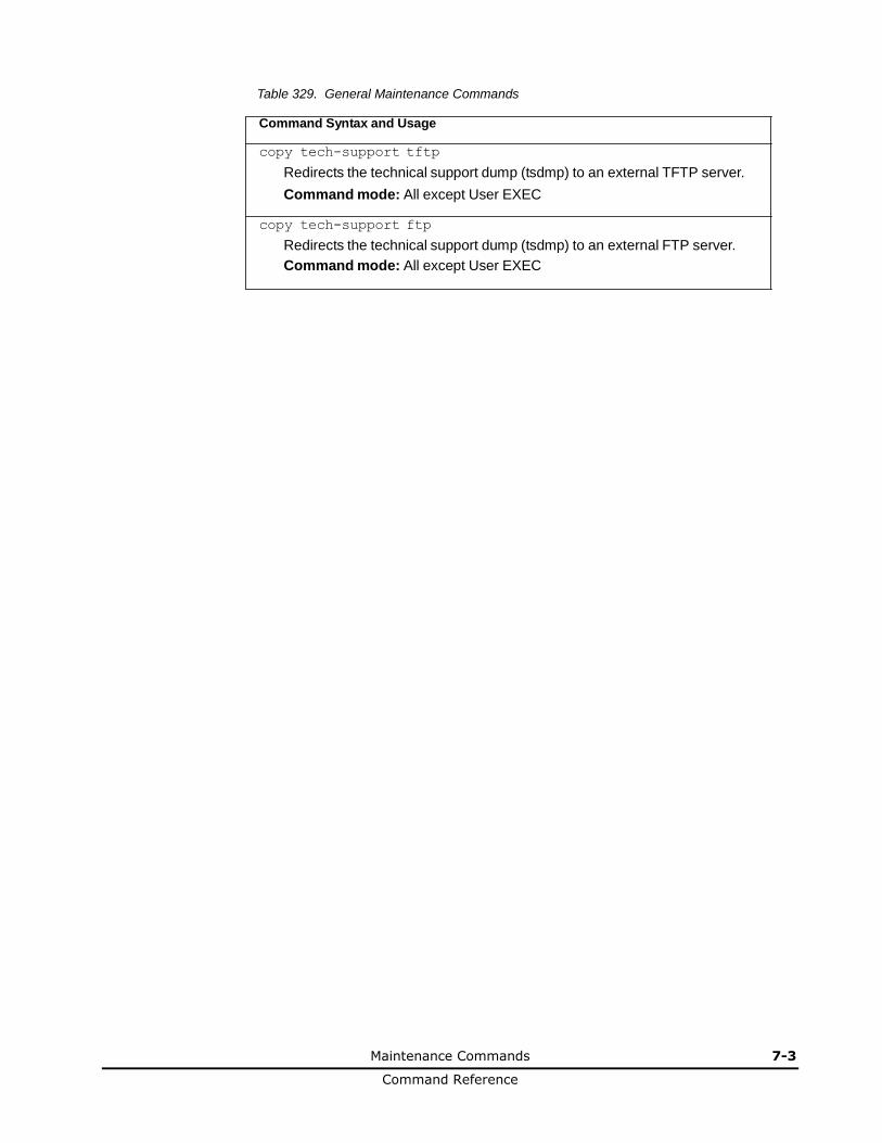
Maintenance Commands 7-3
Command Reference
Table 329. General Maintenance Commands
Command Syntax and Usage
copy tech-support tftp
Redirects the technical support dump (tsdmp) to an external TFTP server.
Command mode: All except User EXEC
copy tech-support ftp
Redirects the technical support dump (tsdmp) to an external FTP server.
Command mode: All except User EXEC
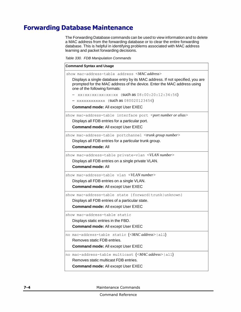
7-4 Maintenance Commands
Command Reference
Forwarding Database Maintenance
The Forwarding Database commands can be used to view information and to delete a MAC address from the forwarding database or to clear the entire forwarding database. This is helpful in identifying problems associated with MAC address learning and packet forwarding decisions.
Table 330. FDB Manipulation Commands
Command Syntax and Usage
show mac-address-table address <MAC address>
Displays a single database entry by its MAC address. If not specified, you are prompted for the MAC address of the device. Enter the MAC address using one of the following formats:
– xx:xx:xx:xx:xx:xx (such as 08:00:20:12:34:56)
– xxxxxxxxxxxx (such as 080020123456)
Command mode: All except User EXEC
show mac-address-table interface port <port number or alias>
Displays all FDB entries for a particular port.
Command mode: All except User EXEC
show mac-address-table portchannel <trunk group number>
Displays all FDB entries for a particular trunk group.
Command mode: All
show mac-address-table private-vlan <VLAN number>
Displays all FDB entries on a single private VLAN.
Command mode: All
show mac-address-table vlan <VLAN number>
Displays all FDB entries on a single VLAN.
Command mode: All except User EXEC
show mac-address-table state {forward|trunk|unknown}
Displays all FDB entries of a particular state.
Command mode: All except User EXEC
show mac-address-table static
Displays static entries in the FBD.
Command mode: All except User EXEC
no mac-address-table static {<MAC address>|all}
Removes static FDB entries.
Command mode: All except User EXEC
no mac-address-table multicast {<MAC address>|all}
Removes static multicast FDB entries.
Command mode: All except User EXEC
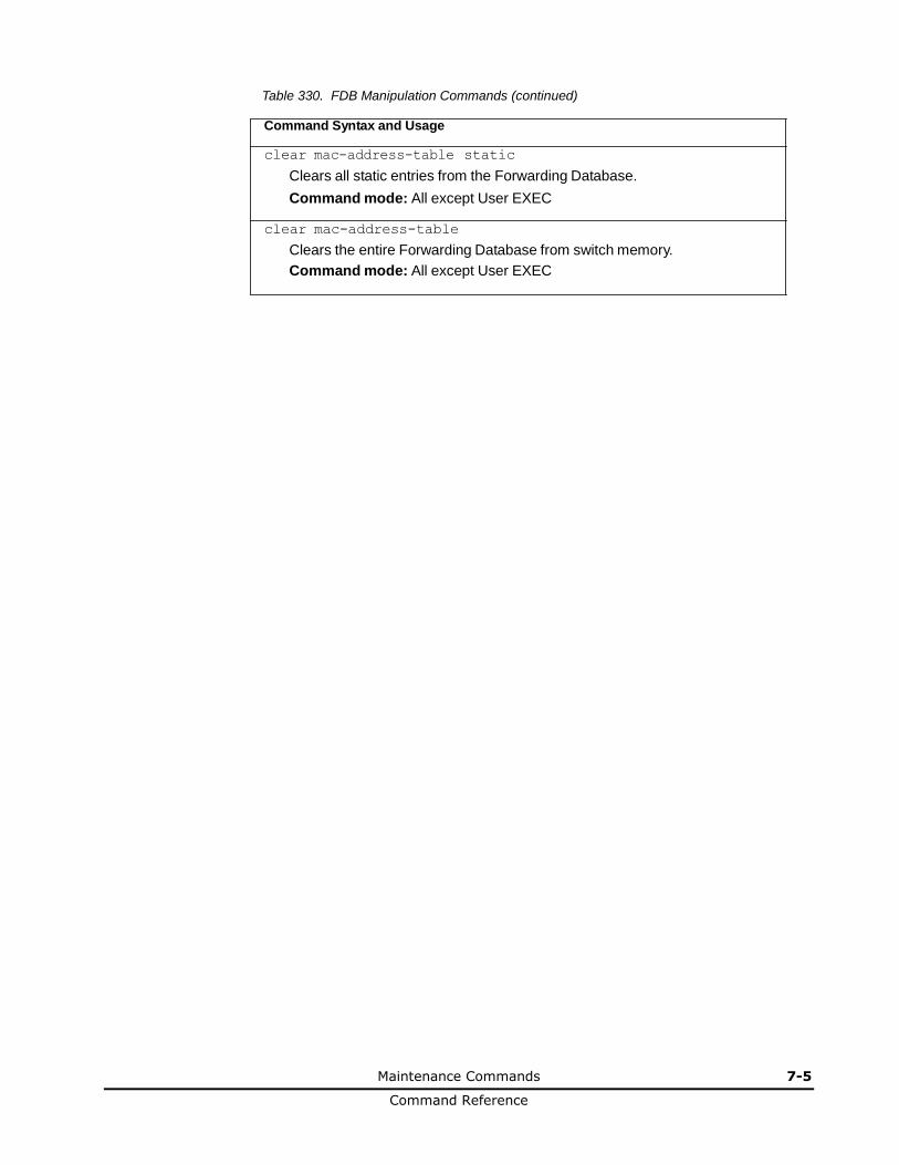
Maintenance Commands 7-5
Command Reference
Table 330. FDB Manipulation Commands (continued)
Command Syntax and Usage
clear mac-address-table static
Clears all static entries from the Forwarding Database.
Command mode: All except User EXEC
clear mac-address-table
Clears the entire Forwarding Database from switch memory.
Command mode: All except User EXEC
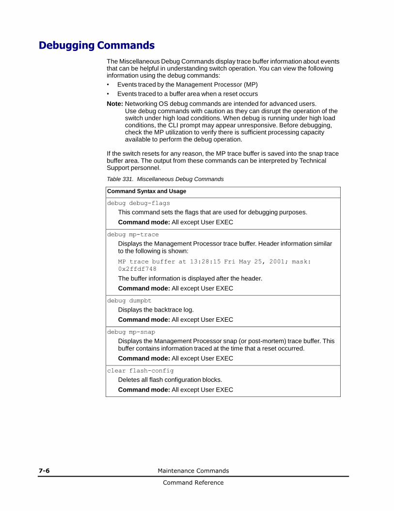
7-6 Maintenance Commands
Command Reference
Debugging Commands
The Miscellaneous Debug Commands display trace buffer information about events that can be helpful in understanding switch operation. You can view the following information using the debug commands:
• Events traced by the Management Processor (MP)
• Events traced to a buffer area when a reset occurs
Note: Networking OS debug commands are intended for advanced users. Use debug commands with caution as they can disrupt the operation of the switch under high load conditions. When debug is running under high load conditions, the CLI prompt may appear unresponsive. Before debugging, check the MP utilization to verify there is sufficient processing capacity available to perform the debug operation.
If the switch resets for any reason, the MP trace buffer is saved into the snap trace buffer area. The output from these commands can be interpreted by Technical Support personnel.
Table 331. Miscellaneous Debug Commands
Command Syntax and Usage
debug debug-flags
This command sets the flags that are used for debugging purposes.
Command mode: All except User EXEC
debug mp-trace
Displays the Management Processor trace buffer. Header information similar to the following is shown:
MP trace buffer at 13:28:15 Fri May 25, 2001; mask:
0x2ffdf748
The buffer information is displayed after the header.
Command mode: All except User EXEC
debug dumpbt
Displays the backtrace log.
Command mode: All except User EXEC
debug mp-snap
Displays the Management Processor snap (or post-mortem) trace buffer. This buffer contains information traced at the time that a reset occurred.
Command mode: All except User EXEC
clear flash-config
Deletes all flash configuration blocks.
Command mode: All except User EXEC
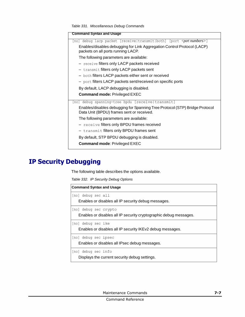
Maintenance Commands 7-7
Command Reference
Table 331. Miscellaneous Debug Commands
Command Syntax and Usage
[no] debug lacp packet [receive|transmit|both] [port <port numbers>]
Enables/disables debugging for Link Aggregation Control Protocol (LACP) packets on all ports running LACP.
The following parameters are available:
– receive filters only LACP packets received
– transmit filters only LACP packets sent
– both filters LACP packets either sent or received
– port filters LACP packets sent/received on specific ports
By default, LACP debugging is disabled.
Command mode: Privileged EXEC
[no] debug spanning-tree bpdu [receive|transmit]
Enables/disables debugging for Spanning Tree Protocol (STP) Bridge Protocol Data Unit (BPDU) frames sent or received.
The following parameters are available:
– receive filters only BPDU frames received
– transmit filters only BPDU frames sent
By default, STP BPDU debugging is disabled.
Command mode: Privileged EXEC
IP Security Debugging
The following table describes the options available.
Table 332. IP Security Debug Options
Command Syntax and Usage
[no] debug sec all
Enables or disables all IP security debug messages.
[no] debug sec crypto
Enables or disables all IP security cryptographic debug messages.
[no] debug sec ike
Enables or disables all IP security IKEv2 debug messages.
[no] debug sec ipsec
Enables or disables all IPsec debug messages.
[no] debug sec info
Displays the current security debug settings.
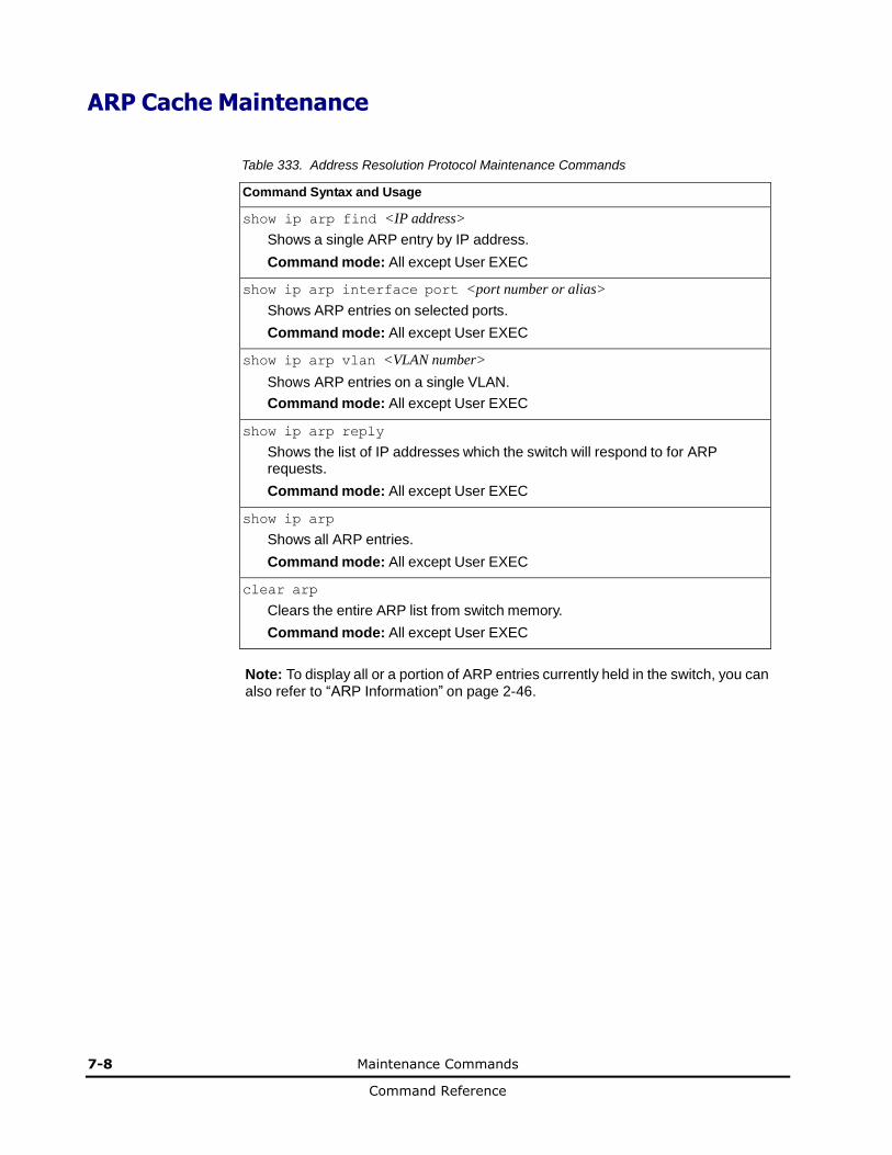
7-8 Maintenance Commands
Command Reference
ARP Cache Maintenance
Table 333. Address Resolution Protocol Maintenance Commands
Command Syntax and Usage
show ip arp find <IP address>
Shows a single ARP entry by IP address.
Command mode: All except User EXEC
show ip arp interface port <port number or alias>
Shows ARP entries on selected ports.
Command mode: All except User EXEC
show ip arp vlan <VLAN number>
Shows ARP entries on a single VLAN.
Command mode: All except User EXEC
show ip arp reply
Shows the list of IP addresses which the switch will respond to for ARP requests.
Command mode: All except User EXEC
show ip arp
Shows all ARP entries.
Command mode: All except User EXEC
clear arp
Clears the entire ARP list from switch memory.
Command mode: All except User EXEC
Note: To display all or a portion of ARP entries currently held in the switch, you can also refer to “ARP Information” on page 2-46.
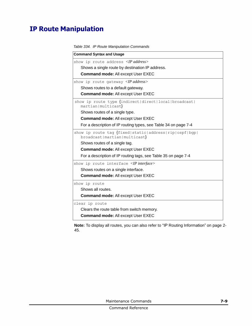
Maintenance Commands 7-9
Command Reference
IP Route Manipulation
Table 334. IP Route Manipulation Commands
Command Syntax and Usage
show ip route address <IP address>
Shows a single route by destination IP address.
Command mode: All except User EXEC
show ip route gateway <IP address>
Shows routes to a default gateway.
Command mode: All except User EXEC
show ip route type {indirect|direct|local|broadcast| martian|multicast}
Shows routes of a single type.
Command mode: All except User EXEC
For a description of IP routing types, see Table 34 on page 7-4
show ip route tag {fixed|static|address|rip|ospf|bgp| broadcast|martian|multicast}
Shows routes of a single tag.
Command mode: All except User EXEC
For a description of IP routing tags, see Table 35 on page 7-4
show ip route interface <IP interface>
Shows routes on a single interface.
Command mode: All except User EXEC
show ip route
Shows all routes.
Command mode: All except User EXEC
clear ip route
Clears the route table from switch memory.
Command mode: All except User EXEC
Note: To display all routes, you can also refer to “IP Routing Information” on page 2-45.
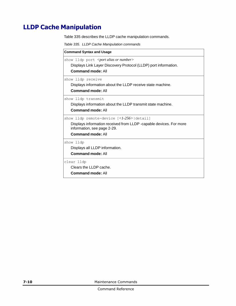
7-10 Maintenance Commands
Command Reference
LLDP Cache Manipulation
Table 335 describes the LLDP cache manipulation commands.
Table 335. LLDP Cache Manipulation commands
Command Syntax and Usage
show lldp port <port alias or number>
Displays Link Layer Discovery Protocol (LLDP) port information.
Command mode: All
show lldp receive
Displays information about the LLDP receive state machine.
Command mode: All
show lldp transmit
Displays information about the LLDP transmit state machine.
Command mode: All
show lldp remote-device [<1-256>|detail]
Displays information received from LLDP -capable devices. For more information, see page 2-29.
Command mode: All
show lldp
Displays all LLDP information.
Command mode: All
clear lldp
Clears the LLDP cache.
Command mode: All
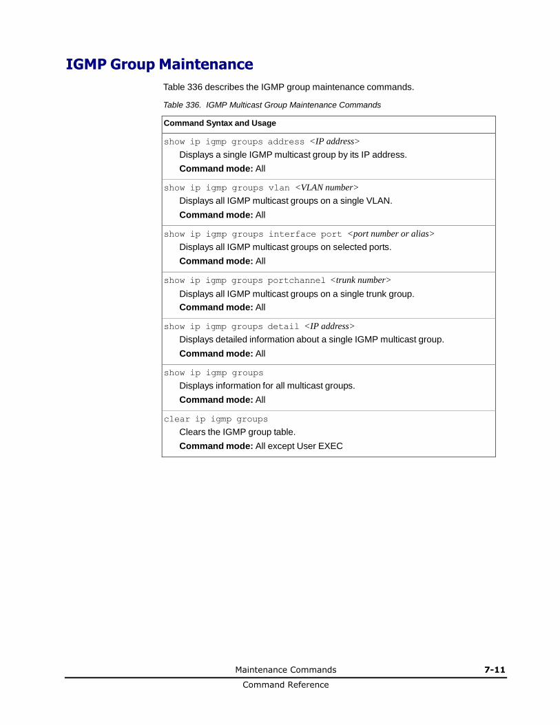
Maintenance Commands 7-11
Command Reference
IGMP Group Maintenance
Table 336 describes the IGMP group maintenance commands.
Table 336. IGMP Multicast Group Maintenance Commands
Command Syntax and Usage
show ip igmp groups address <IP address>
Displays a single IGMP multicast group by its IP address.
Command mode: All
show ip igmp groups vlan <VLAN number>
Displays all IGMP multicast groups on a single VLAN.
Command mode: All
show ip igmp groups interface port <port number or alias>
Displays all IGMP multicast groups on selected ports.
Command mode: All
show ip igmp groups portchannel <trunk number>
Displays all IGMP multicast groups on a single trunk group.
Command mode: All
show ip igmp groups detail <IP address>
Displays detailed information about a single IGMP multicast group.
Command mode: All
show ip igmp groups
Displays information for all multicast groups.
Command mode: All
clear ip igmp groups
Clears the IGMP group table.
Command mode: All except User EXEC
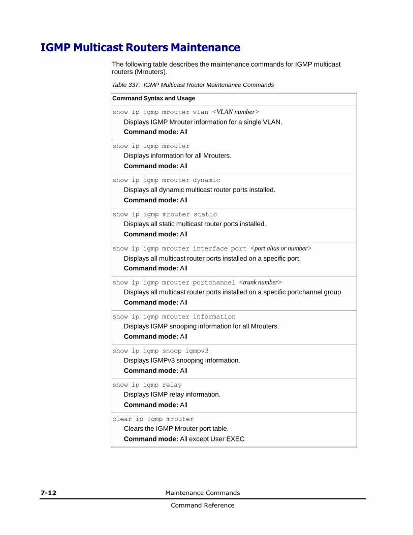
7-12 Maintenance Commands
Command Reference
IGMP Multicast Routers Maintenance
The following table describes the maintenance commands for IGMP multicast routers (Mrouters).
Table 337. IGMP Multicast Router Maintenance Commands
Command Syntax and Usage
show ip igmp mrouter vlan <VLAN number>
Displays IGMP Mrouter information for a single VLAN.
Command mode: All
show ip igmp mrouter
Displays information for all Mrouters.
Command mode: All
show ip igmp mrouter dynamic
Displays all dynamic multicast router ports installed.
Command mode: All
show ip igmp mrouter static
Displays all static multicast router ports installed.
Command mode: All
show ip igmp mrouter interface port <port alias or number>
Displays all multicast router ports installed on a specific port.
Command mode: All
show ip igmp mrouter portchannel <trunk number>
Displays all multicast router ports installed on a specific portchannel group.
Command mode: All
show ip igmp mrouter information
Displays IGMP snooping information for all Mrouters.
Command mode: All
show ip igmp snoop igmpv3
Displays IGMPv3 snooping information.
Command mode: All
show ip igmp relay
Displays IGMP relay information.
Command mode: All
clear ip igmp mrouter
Clears the IGMP Mrouter port table.
Command mode: All except User EXEC

Maintenance Commands 7-13
Command Reference
MLD Multicast Group Manipulation
Table 338 describes the Multicast Listener Discovery (MLD) manipulation options.
Table 338. MLD Maintenance
Command Syntax and Usage
show ipv6 mld groups
Shows all MLD groups.
Command mode: All
show ipv6 mld interface <interface number>
Shows MLD groups on the specified interface.
Command mode: All
clear ipv6 mld mrouter
Clears all dynamic MLD multicast router group tables.
Command mode: All except User EXEC
clear ipv6 mld groups
Clears all dynamic MLD registered group tables.
Command mode: All except User EXEC
clear ipv6 mld dynamic
Clears all dynamic MLD group tables.
Command mode: All except User EXEC
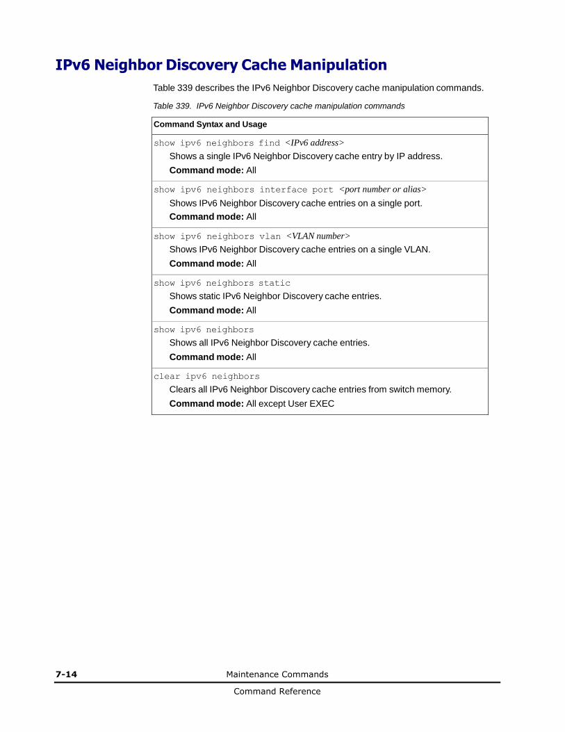
7-14 Maintenance Commands
Command Reference
IPv6 Neighbor Discovery Cache Manipulation
Table 339 describes the IPv6 Neighbor Discovery cache manipulation commands.
Table 339. IPv6 Neighbor Discovery cache manipulation commands
Command Syntax and Usage
show ipv6 neighbors find <IPv6 address>
Shows a single IPv6 Neighbor Discovery cache entry by IP address.
Command mode: All
show ipv6 neighbors interface port <port number or alias>
Shows IPv6 Neighbor Discovery cache entries on a single port.
Command mode: All
show ipv6 neighbors vlan <VLAN number>
Shows IPv6 Neighbor Discovery cache entries on a single VLAN.
Command mode: All
show ipv6 neighbors static
Shows static IPv6 Neighbor Discovery cache entries.
Command mode: All
show ipv6 neighbors
Shows all IPv6 Neighbor Discovery cache entries.
Command mode: All
clear ipv6 neighbors
Clears all IPv6 Neighbor Discovery cache entries from switch memory.
Command mode: All except User EXEC
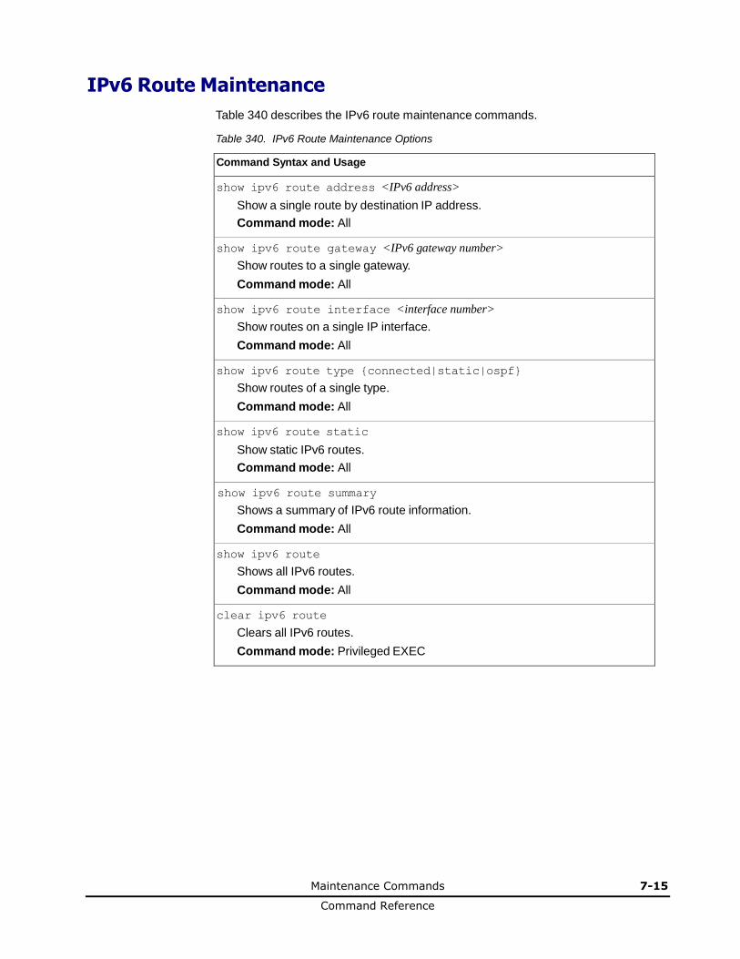
Maintenance Commands 7-15
Command Reference
IPv6 Route Maintenance
Table 340 describes the IPv6 route maintenance commands.
Table 340. IPv6 Route Maintenance Options
Command Syntax and Usage
show ipv6 route address <IPv6 address>
Show a single route by destination IP address.
Command mode: All
show ipv6 route gateway <IPv6 gateway number>
Show routes to a single gateway.
Command mode: All
show ipv6 route interface <interface number>
Show routes on a single IP interface.
Command mode: All
show ipv6 route type {connected|static|ospf}
Show routes of a single type.
Command mode: All
show ipv6 route static
Show static IPv6 routes.
Command mode: All
show ipv6 route summary
Shows a summary of IPv6 route information.
Command mode: All
show ipv6 route
Shows all IPv6 routes.
Command mode: All
clear ipv6 route
Clears all IPv6 routes.
Command mode: Privileged EXEC

7-16 Maintenance Commands
Command Reference
Uuencode Flash Dump
Using this command, dump information is presented in uuencoded format. This format makes it easy to capture the dump information as a file or a string of characters.
If you want to capture dump information to a file, set your communication software on your workstation to capture session data prior to issuing the show flash-dump-uuencode command. This will ensure that you do not lose any information. Once entered, the show flash-dump-uuencode command will cause approximately 23,300 lines of data to be displayed on your screen and copied into the file.
Using the show flash-dump-uuencode command, dump information can be read multiple times. The command does not cause the information to be updated or cleared from flash memory.
Note: Dump information is not cleared automatically. In order for any subsequent dump information to be written to flash memory, you must manually clear the dump region. For more information on clearing the dump region, see page 7-18.
To access dump information, enter:
Router# show flash-dump-uuencode
The dump information is displayed on your screen and, if you have configured your communication software to do so, captured to a file. If the dump region is empty, the following appears:
No FLASH dump available.

Maintenance Commands 7-17
Command Reference
TFTP, SFTP or FTP System Dump Put
Use these commands to put (save) the system dump to a TFTP or FTP server.
Note: If the TFTP/FTP server is running SunOS or the Solaris operating system, the specified copy flash-dump tftp (or ftp) file must exist prior to executing the copy flash-dump tftp command (or copy flash-dump tftp), and must be writable (set with proper permission, and not locked by any application). The contents of the specified file will be replaced with the current dump data.
To save dump information via TFTP, enter:
Router# copy flash-dump tftp [data-port|mgt-port] <server filename>
You are prompted for the TFTP server IP address or hostname, and the filename of the target dump file.
To save dump information via SFTP, enter:
Router# copy flash-dump sftp [data-port|mgt-port] <server filename>
You are prompted for the SFTP server IP address or hostname, your username and password, and the filename of the target dump file.
To save dump information via FTP, enter:
Router# copy flash-dump ftp [data-port|mgt-port] <server filename>
You are prompted for the FTP server IP address or hostname, your username and password, and the filename of the target dump file.
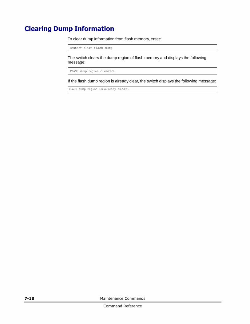
7-18 Maintenance Commands
Command Reference
Clearing Dump Information
To clear dump information from flash memory, enter:
Router# clear flash-dump
The switch clears the dump region of flash memory and displays the following message:
FLASH dump region cleared.
If the flash dump region is already clear, the switch displays the following message:
FLASH dump region is already clear.

Maintenance Commands 7-19
Command Reference
Unscheduled System Dumps
If there is an unscheduled system dump to flash memory, the following message is displayed when you log on to the switch:
Note: A system dump exists in FLASH. The dump was saved
at 13:43:22 Wednesday January 30, 2010. Use show flash-dump
uuencode to
extract the dump for analysis and clear flash-dump to clear
the FLASH region. The region must be cleared before another
dump can be saved.

7-20 Maintenance Commands
Command Reference
A
Appendix A A-1
Command Reference
Appendix A This chapter describes the System Log Messages of Networking OS for 1/10Gb LAN Switch Module.
Networking OS System Log Messages
LOG_ALERT
LOG_CRIT
LOG_ERR
LOG_INFO
LOG_NOTICE
LOG_WARNING
A-2 Appendix A
Command Reference
Networking OS System Log Messages
The 1/10Gb LAN Switch Module uses the following syntax when outputting system log (syslog) messages:
<Time stamp> <IP/Hostname><Log Label>OS<Thread ID>:<Message>
The following parameters are used:
• <Timestamp>
The time of the message event is displayed in the following format:
<month (3 characters)> <day> <hour (1-24)>:<minute>:<second>
For example: Aug 19 14:20:30
• <IP/Hostname>
The hostname is displayed when configured.
For example: 1.1.1.1
• <Log Label>
The following types of log messages are recorded: LOG_CRIT, LOG_WARNING, LOG_ALERT, LOG_ERR, LOG_NOTICE, and LOG_INFO
• <Thread ID>
This is the software thread that reports the log message. For example:
stg, ip, console, telnet, vrrp, system, web server, ssh, bgp
• <Message>: The log message
Following is a list of potential syslog messages. To keep this list as short as possible, only the <Thread ID> and <Message> are shown. The messages are sorted by <Log Label>.
Where the <Thread ID> is listed as mgmt, one of the following may be shown:
console, telnet, web server, or ssh.
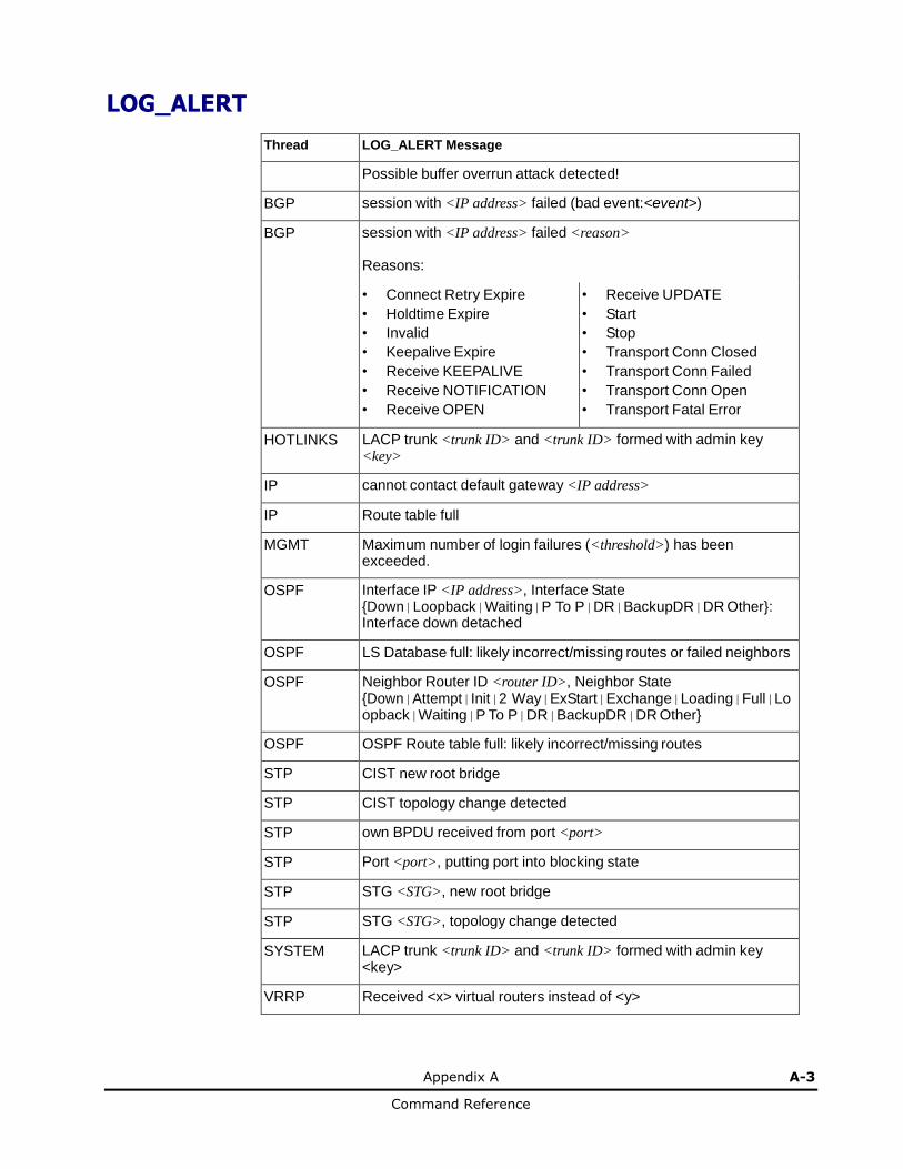
Appendix A A-3
Command Reference
LOG_ALERT
Thread LOG_ALERT Message
Possible buffer overrun attack detected!
BGP session with <IP address> failed (bad event:<event>)
BGP session with <IP address> failed <reason> Reasons:
• Connect Retry Expire
• Holdtime Expire
• Invalid
• Keepalive Expire
• Receive KEEPALIVE
• Receive NOTIFICATION
• Receive OPEN
• Receive UPDATE
• Start
• Stop
• Transport Conn Closed
• Transport Conn Failed
• Transport Conn Open
• Transport Fatal Error
HOTLINKS LACP trunk <trunk ID> and <trunk ID> formed with admin key <key>
IP cannot contact default gateway <IP address>
IP Route table full
MGMT Maximum number of login failures (<threshold>) has been exceeded.
OSPF Interface IP <IP address>, Interface State {Down|Loopback|Waiting|P To P|DR|BackupDR|DR Other}: Interface down detached
OSPF LS Database full: likely incorrect/missing routes or failed neighbors
OSPF Neighbor Router ID <router ID>, Neighbor State {Down|Attempt|Init|2 Way|ExStart|Exchange|Loading|Full|Lo opback|Waiting|P To P|DR|BackupDR|DR Other}
OSPF OSPF Route table full: likely incorrect/missing routes
STP CIST new root bridge
STP CIST topology change detected
STP own BPDU received from port <port>
STP Port <port>, putting port into blocking state
STP STG <STG>, new root bridge
STP STG <STG>, topology change detected
SYSTEM LACP trunk <trunk ID> and <trunk ID> formed with admin key <key>
VRRP Received <x> virtual routers instead of <y>
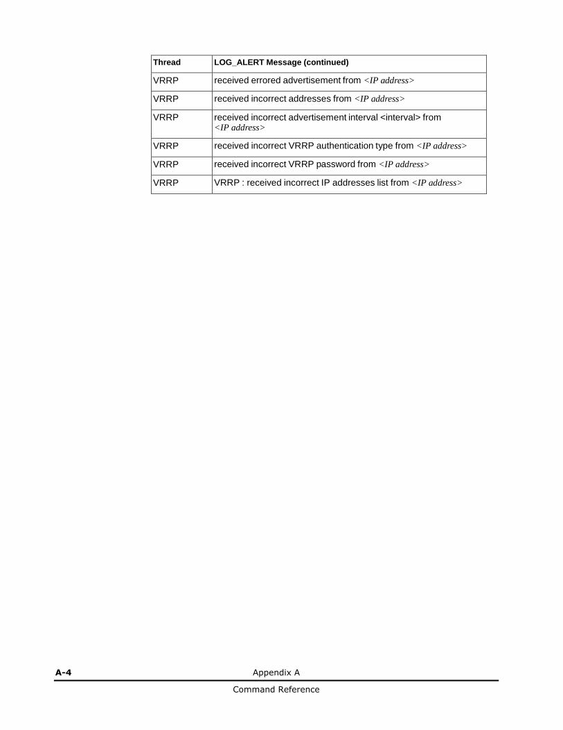
A-4 Appendix A
Command Reference
Thread LOG_ALERT Message (continued)
VRRP received errored advertisement from <IP address>
VRRP received incorrect addresses from <IP address>
VRRP received incorrect advertisement interval <interval> from <IP address>
VRRP received incorrect VRRP authentication type from <IP address>
VRRP received incorrect VRRP password from <IP address>
VRRP VRRP : received incorrect IP addresses list from <IP address>

Appendix A A-5
Command Reference
LOG_CRIT
Thread LOG_CRIT Message
SSH can't allocate memory in load_MP_INT()
SSH currently not enough resource for loading RSA {private|public key}
SYSTEM System memory is at <n> percent
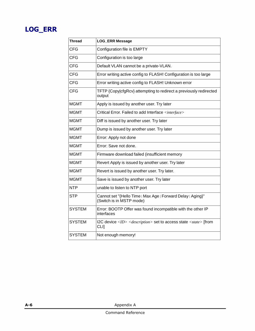
A-6 Appendix A
Command Reference
LOG_ERR
Thread LOG_ERR Message
CFG Configuration file is EMPTY
CFG Configuration is too large
CFG Default VLAN cannot be a private-VLAN.
CFG Error writing active config to FLASH! Configuration is too large
CFG Error writing active config to FLASH! Unknown error
CFG TFTP {Copy|cfgRcv} attempting to redirect a previously redirected output
MGMT Apply is issued by another user. Try later
MGMT Critical Error. Failed to add Interface <interface>
MGMT Diff is issued by another user. Try later
MGMT Dump is issued by another user. Try later
MGMT Error: Apply not done
MGMT Error: Save not done.
MGMT Firmware download failed (insufficient memory
MGMT Revert Apply is issued by another user. Try later
MGMT Revert is issued by another user. Try later.
MGMT Save is issued by another user. Try later
NTP unable to listen to NTP port
STP Cannot set "{Hello Time|Max Age|Forward Delay|Aging}" (Switch is in MSTP mode)
SYSTEM Error: BOOTP Offer was found incompatible with the other IP interfaces
SYSTEM I2C device <ID> <description> set to access state <state> [from CLI]
SYSTEM Not enough memory!
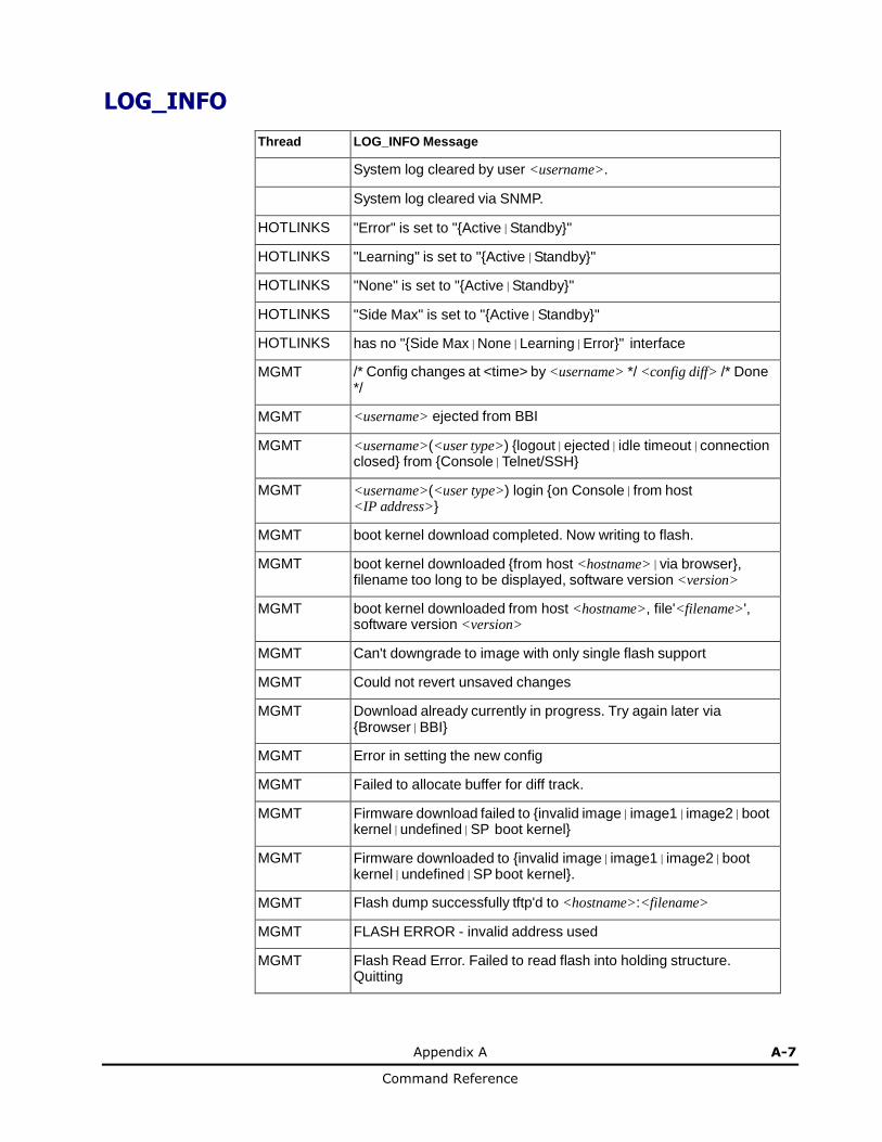
Appendix A A-7
Command Reference
LOG_INFO
Thread LOG_INFO Message
System log cleared by user <username>.
System log cleared via SNMP.
HOTLINKS "Error" is set to "{Active|Standby}"
HOTLINKS "Learning" is set to "{Active|Standby}"
HOTLINKS "None" is set to "{Active|Standby}"
HOTLINKS "Side Max" is set to "{Active|Standby}"
HOTLINKS has no "{Side Max|None|Learning|Error}" interface
MGMT /* Config changes at <time> by <username> */ <config diff> /* Done */
MGMT <username> ejected from BBI
MGMT <username>(<user type>) {logout|ejected|idle timeout|connection closed} from {Console|Telnet/SSH}
MGMT <username>(<user type>) login {on Console|from host <IP address>}
MGMT boot kernel download completed. Now writing to flash.
MGMT boot kernel downloaded {from host <hostname>|via browser}, filename too long to be displayed, software version <version>
MGMT boot kernel downloaded from host <hostname>, file'<filename>', software version <version>
MGMT Can't downgrade to image with only single flash support
MGMT Could not revert unsaved changes
MGMT Download already currently in progress. Try again later via {Browser|BBI}
MGMT Error in setting the new config
MGMT Failed to allocate buffer for diff track.
MGMT Firmware download failed to {invalid image|image1|image2|boot kernel|undefined|SP boot kernel}
MGMT Firmware downloaded to {invalid image|image1|image2|boot kernel|undefined|SP boot kernel}.
MGMT Flash dump successfully tftp'd to <hostname>:<filename>
MGMT FLASH ERROR - invalid address used
MGMT Flash Read Error. Failed to read flash into holding structure. Quitting

A-8 Appendix A
Command Reference
Thread LOG_INFO Message (continued)
MGMT Flash Write Error
MGMT Flash Write Error. Failed to allocate buffer. Quitting
MGMT Flash Write Error. Trying again
MGMT image1|2 download completed. Now writing to flash.
MGMT image1|2 downloaded {from host <hostname>|via browser}, filename too long to be displayed, software version <version>
MGMT image1|2 downloaded from host <hostname>, file'<filename>', software version <version>
MGMT Incorrect image being loaded
MGMT Invalid diff track address. Continuing with apply()
MGMT Invalid image being loaded for this switch type
MGMT invalid image download completed. Now writing to flash.
MGMT invalid image downloaded {from host <hostname>|via browser}, filename too long to be displayed, software version <version>
MGMT invalid image downloaded from host <hostname>, file '<filename>', software version <version>
MGMT New config set
MGMT new configuration applied [from BBI|EM|SCP|SNMP]
MGMT new configuration saved from {BBI|CLI|SNMP}
MGMT scp<username>(<user type>) {logout|ejected|idle timeout|connection closed} from {Console|Telnet/SSH}
MGMT scp<username>(<user type>) login {on Console|from host <IP address>}
MGMT SP boot kernel download completed. Now writing to flash.
MGMT SP boot kernel downloaded {from host <hostname>|via browser}, filename too long to be displayed, software version <version>
MGMT SP boot kernel downloaded from host <hostname>, file '<filename>', software version <version>
MGMT Starting Firmware download for {invalid image|image1|image2|boot kernel|undefined|SP boot kernel}.
MGMT Static FDB entry on disabled VLAN
MGMT Tech support dump failed
MGMT Tech support dump successfully tftp'd to <hostname>:<filename>
MGMT Two Phase Apply Failed in Creating Backup Config Block.
MGMT undefined download completed. Now writing to flash.
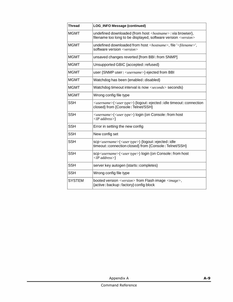
Appendix A A-9
Command Reference
Thread LOG_INFO Message (continued)
MGMT undefined downloaded {from host <hostname>|via browser}, filename too long to be displayed, software version <version>
MGMT undefined downloaded from host <hostname>, file '<filename>', software version <version>
MGMT unsaved changes reverted [from BBI|from SNMP]
MGMT Unsupported GBIC {accepted|refused}
MGMT user {SNMP user|<username>} ejected from BBI
MGMT Watchdog has been {enabled|disabled}
MGMT Watchdog timeout interval is now <seconds> seconds)
MGMT Wrong config file type
SSH <username>(<user type>) {logout|ejected|idle timeout|connection closed} from {Console|Telnet/SSH}
SSH <username>(<user type>) login {on Console|from host <IP address>}
SSH Error in setting the new config
SSH New config set
SSH scp<username>(<user type>) {logout|ejected|idle timeout|connection closed} from {Console|Telnet/SSH}
SSH scp<username>(<user type>) login {on Console|from host <IP address>}
SSH server key autogen {starts|completes}
SSH Wrong config file type
SYSTEM booted version <version> from Flash image <image>, {active|backup|factory} config block
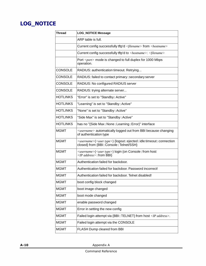
A-10 Appendix A
Command Reference
LOG_NOTICE
Thread LOG_NOTICE Message
ARP table is full.
Current config successfully tftp'd <filename> from <hostname>
Current config successfully tftp'd to <hostname>: <filename>
Port <port> mode is changed to full duplex for 1000 Mbps operation.
CONSOLE RADIUS: authentication timeout. Retrying...
CONSOLE RADIUS: failed to contact primary|secondary server
CONSOLE RADIUS: No configured RADIUS server
CONSOLE RADIUS: trying alternate server...
HOTLINKS "Error" is set to "Standby|Active"
HOTLINKS "Learning" is set to "Standby|Active"
HOTLINKS "None" is set to "Standby|Active"
HOTLINKS "Side Max" is set to "Standby|Active"
HOTLINKS has no "{Side Max|None|Learning|Error}" interface
MGMT <username> automatically logged out from BBI because changing of authentication type
MGMT <username>(<user type>) {logout|ejected|idle timeout|connection closed} from {BBI|Console|Telnet/SSH}
MGMT <username>(<user type>) login {on Console|from host <IP address>|from BBI}
MGMT Authentication failed for backdoor.
MGMT Authentication failed for backdoor. Password incorrect!
MGMT Authentication failed for backdoor. Telnet disabled!
MGMT boot config block changed
MGMT boot image changed
MGMT boot mode changed
MGMT enable password changed
MGMT Error in setting the new config
MGMT Failed login attempt via {BBI|TELNET} from host <IP address>.
MGMT Failed login attempt via the CONSOLE
MGMT FLASH Dump cleared from BBI
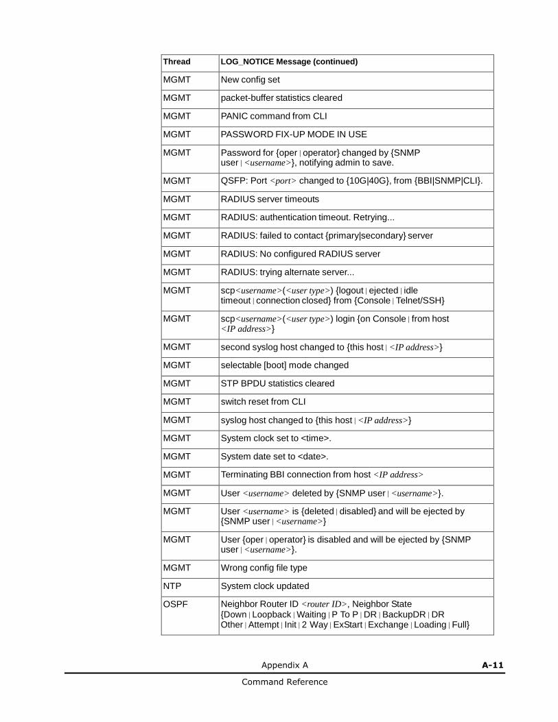
Appendix A A-11
Command Reference
Thread LOG_NOTICE Message (continued)
MGMT New config set
MGMT packet-buffer statistics cleared
MGMT PANIC command from CLI
MGMT PASSWORD FIX-UP MODE IN USE
MGMT Password for {oper|operator} changed by {SNMP user|<username>}, notifying admin to save.
MGMT QSFP: Port <port> changed to {10G|40G}, from {BBI|SNMP|CLI}.
MGMT RADIUS server timeouts
MGMT RADIUS: authentication timeout. Retrying...
MGMT RADIUS: failed to contact {primary|secondary} server
MGMT RADIUS: No configured RADIUS server
MGMT RADIUS: trying alternate server...
MGMT scp<username>(<user type>) {logout|ejected|idle timeout|connection closed} from {Console|Telnet/SSH}
MGMT scp<username>(<user type>) login {on Console|from host <IP address>}
MGMT second syslog host changed to {this host|<IP address>}
MGMT selectable [boot] mode changed
MGMT STP BPDU statistics cleared
MGMT switch reset from CLI
MGMT syslog host changed to {this host|<IP address>}
MGMT System clock set to <time>.
MGMT System date set to <date>.
MGMT Terminating BBI connection from host <IP address>
MGMT User <username> deleted by {SNMP user|<username>}.
MGMT User <username> is {deleted|disabled} and will be ejected by {SNMP user|<username>}
MGMT User {oper|operator} is disabled and will be ejected by {SNMP user|<username>}.
MGMT Wrong config file type
NTP System clock updated
OSPF Neighbor Router ID <router ID>, Neighbor State {Down|Loopback|Waiting|P To P|DR|BackupDR|DR Other|Attempt|Init|2 Way|ExStart|Exchange|Loading|Full}
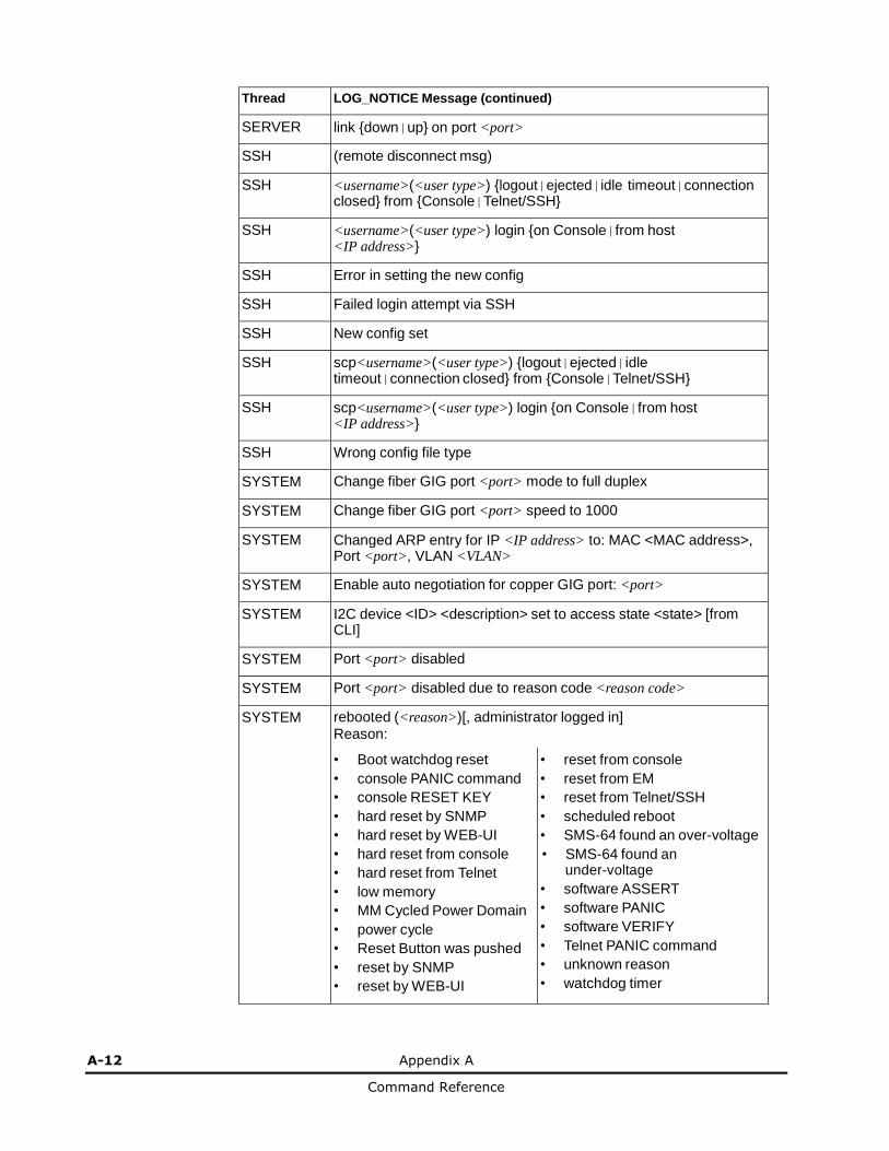
A-12 Appendix A
Command Reference
Thread LOG_NOTICE Message (continued)
SERVER link {down|up} on port <port>
SSH (remote disconnect msg)
SSH <username>(<user type>) {logout|ejected|idle timeout|connection closed} from {Console|Telnet/SSH}
SSH <username>(<user type>) login {on Console|from host <IP address>}
SSH Error in setting the new config
SSH Failed login attempt via SSH
SSH New config set
SSH scp<username>(<user type>) {logout|ejected|idle timeout|connection closed} from {Console|Telnet/SSH}
SSH scp<username>(<user type>) login {on Console|from host <IP address>}
SSH Wrong config file type
SYSTEM Change fiber GIG port <port> mode to full duplex
SYSTEM Change fiber GIG port <port> speed to 1000
SYSTEM Changed ARP entry for IP <IP address> to: MAC <MAC address>, Port <port>, VLAN <VLAN>
SYSTEM Enable auto negotiation for copper GIG port: <port>
SYSTEM I2C device <ID> <description> set to access state <state> [from CLI]
SYSTEM Port <port> disabled
SYSTEM Port <port> disabled due to reason code <reason code>
SYSTEM rebooted (<reason>)[, administrator logged in] Reason:
• Boot watchdog reset
• console PANIC command
• console RESET KEY
• hard reset by SNMP
• hard reset by WEB-UI
• hard reset from console
• hard reset from Telnet
• low memory
• MM Cycled Power Domain
• power cycle
• Reset Button was pushed
• reset by SNMP
• reset by WEB-UI
• reset from console
• reset from EM
• reset from Telnet/SSH
• scheduled reboot
• SMS-64 found an over-voltage
• SMS-64 found an under-voltage
• software ASSERT
• software PANIC
• software VERIFY
• Telnet PANIC command
• unknown reason
• watchdog timer

Appendix A A-13
Command Reference
Thread LOG_NOTICE Message (continued)
SYSTEM Received BOOTP Offer: IP: <IP address>, Mask: <netmask>, Broadcast <IP address>, GW: <IP address>
SYSTEM Watchdog threshold changed from <old value> to <new value> seconds
SYSTEM Watchdog timer has been enabled
TEAMING error, action is undefined
TEAMING is down, but teardown is blocked
TEAMING is down, control ports are auto disabled
TEAMING is up, control ports are auto controlled
VLAN Default VLAN can not be deleted
VRRP virtual router <IP address> is now {BACKUP|MASTER}
WEB <username> ejected from BBI
WEB RSA host key is being saved to Flash ROM, please don't reboot the box immediately.
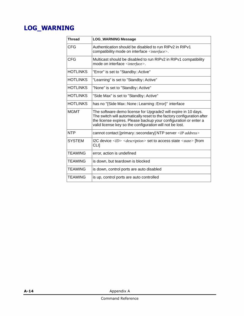
A-14 Appendix A
Command Reference
LOG_WARNING
Thread LOG_WARNING Message
CFG Authentication should be disabled to run RIPv2 in RIPv1 compatibility mode on interface <interface>.
CFG Multicast should be disabled to run RIPv2 in RIPv1 compatibility mode on interface <interface>.
HOTLINKS "Error" is set to "Standby|Active"
HOTLINKS "Learning" is set to "Standby|Active"
HOTLINKS "None" is set to "Standby|Active"
HOTLINKS "Side Max" is set to "Standby|Active"
HOTLINKS has no "{Side Max|None|Learning|Error}" interface
MGMT The software demo license for Upgrade2 will expire in 10 days. The switch will automatically reset to the factory configuration after the license expires. Please backup your configuration or enter a valid license key so the configuration will not be lost.
NTP cannot contact [primary|secondary] NTP server <IP address>
SYSTEM I2C device <ID> <description> set to access state <state> [from CLI]
TEAMING error, action is undefined
TEAMING is down, but teardown is blocked
TEAMING is down, control ports are auto disabled
TEAMING is up, control ports are auto controlled

Command Reference


![7.8 notes[1]](https://img.pdfslide.us/doc/110x75/547c9b815906b561378b456f/78-notes1.jpg)