Embed Size (px)
Citation preview

IBM Flex System Fabric SI4093 System Interconnect Module
Application Guidefor Networking OS 7.8

Note: Before using this information and the product it supports, read the general information in the Safety information and Environmental Notices and User Guide documents on the IBM Documentation CD and the Warranty Information document that comes with the product.
First Edition, June 2014. Part Number 00CG964
© Copyright IBM Corporation 2014US Government Users Restricted Rights – Use, duplication or disclosure restricted by GSA ADP Schedule Contract with IBM Corp.
© Copyright IBM Corp. 2014 3
Contents
Preface . . . . . . . . . . . . . . . . . . . . . . . . . . . . . 9Who Should Use This Guide . . . . . . . . . . . . . . . . . . . . . 9What You’ll Find in This Guide . . . . . . . . . . . . . . . . . . . . 9Additional References. . . . . . . . . . . . . . . . . . . . . . . 11Typographic Conventions . . . . . . . . . . . . . . . . . . . . . 11How to Get Help . . . . . . . . . . . . . . . . . . . . . . . . . 12
Part 1: Getting Started . . . . . . . . . . . . . . . . . . . . . . 13
Chapter 1. Introduction . . . . . . . . . . . . . . . . . . . . . 15Feature Summary . . . . . . . . . . . . . . . . . . . . . . . . 15Recommended System Deployments . . . . . . . . . . . . . . . . 17
Basic Single-SPAR Topology . . . . . . . . . . . . . . . . . . 17VLAG Topology SPAR Modification . . . . . . . . . . . . . . . . 18Multi-SPAR Topology . . . . . . . . . . . . . . . . . . . . . 19
Recommended Workflow . . . . . . . . . . . . . . . . . . . . . 20
Chapter 2. Administrative Access . . . . . . . . . . . . . . . . . 21Administration Interfaces . . . . . . . . . . . . . . . . . . . . . 21Establishing a Connection . . . . . . . . . . . . . . . . . . . . . 22
Using the Chassis Management Module . . . . . . . . . . . . . . 22Using Telnet . . . . . . . . . . . . . . . . . . . . . . . . . 23Using Secure Shell . . . . . . . . . . . . . . . . . . . . . . 23Using Simple Network Management Protocol . . . . . . . . . . . . 24
BOOTP/DHCP Client IP Address Services. . . . . . . . . . . . . . . 25Host Name Configuration . . . . . . . . . . . . . . . . . . . . 25SYSLOG Server . . . . . . . . . . . . . . . . . . . . . . . 26
System Login Levels . . . . . . . . . . . . . . . . . . . . . . . 26
Chapter 3. Initial Setup. . . . . . . . . . . . . . . . . . . . . . 29Information Needed for Setup. . . . . . . . . . . . . . . . . . . . 29Default Setup Options. . . . . . . . . . . . . . . . . . . . . . . 29Stopping and Restarting Setup Manually . . . . . . . . . . . . . . . 30Setup Part 1: Basic System Configuration . . . . . . . . . . . . . . . 30Setup Part 2: Port Configuration. . . . . . . . . . . . . . . . . . . 32Setup Part 3: IP Configuration . . . . . . . . . . . . . . . . . . . 33
IP Interfaces . . . . . . . . . . . . . . . . . . . . . . . . . 33Default Gateways . . . . . . . . . . . . . . . . . . . . . . . 35
Setup Part 4: Final Steps . . . . . . . . . . . . . . . . . . . . . 35Optional Setup for Telnet Support . . . . . . . . . . . . . . . . . . 36
Chapter 4. Updating the System Software . . . . . . . . . . . . . . 37Determining the Current Software Version . . . . . . . . . . . . . . . 37Getting the Latest SI4093 Software . . . . . . . . . . . . . . . . . 37Loading New Software to Your SI4093 . . . . . . . . . . . . . . . . 38Recovering from a Failed Upgrade. . . . . . . . . . . . . . . . . . 40

4 SI4093 10Gb System Interconnect Module: Application Guide
Chapter 5. System License Keys . . . . . . . . . . . . . . . . . 43Obtaining Activation Keys . . . . . . . . . . . . . . . . . . . . . 44Installing Activation Keys . . . . . . . . . . . . . . . . . . . . . 45Transferring Activation Keys . . . . . . . . . . . . . . . . . . . . 45
Part 2: Securing the SI4093. . . . . . . . . . . . . . . . . . . . 47
Chapter 6. Administrative Security . . . . . . . . . . . . . . . . 49Changing the System Passwords . . . . . . . . . . . . . . . . . . 49Secure Shell and Secure Copy . . . . . . . . . . . . . . . . . . . 50
Configuring SSH/SCP . . . . . . . . . . . . . . . . . . . . . 51Configuring the SCP Administrator Password. . . . . . . . . . . . 51Using SSH and SCP Client Commands . . . . . . . . . . . . . . 52SSH and SCP Encryption of Management Messages . . . . . . . . 54Generating the RSA Host Key for SSH Access . . . . . . . . . . . 54SSH/SCP Integration with RADIUS Authentication. . . . . . . . . . 54SSH/SCP Integration with TACACS+ Authentication . . . . . . . . . 54
Secure FTP . . . . . . . . . . . . . . . . . . . . . . . . . . 55End User Access Control . . . . . . . . . . . . . . . . . . . . . 55
Considerations for Configuring End User Accounts . . . . . . . . . 55Strong Passwords . . . . . . . . . . . . . . . . . . . . . . 55User Access Control Menu . . . . . . . . . . . . . . . . . . . 56Listing Current Users . . . . . . . . . . . . . . . . . . . . . 57Logging In to an End User Account. . . . . . . . . . . . . . . . 57
Boot Strict Mode . . . . . . . . . . . . . . . . . . . . . . . . 58Acceptable Cipher Suites . . . . . . . . . . . . . . . . . . . 61Configuring Strict Mode . . . . . . . . . . . . . . . . . . . . 62Boot Strict Mode Limitations . . . . . . . . . . . . . . . . . . 62
Protected Mode . . . . . . . . . . . . . . . . . . . . . . . . . 63
Chapter 7. Authentication & Authorization Protocols . . . . . . . . . 65RADIUS Authentication and Authorization. . . . . . . . . . . . . . . 65
How RADIUS Authentication Works . . . . . . . . . . . . . . . 65Configuring RADIUS on the SI4093 . . . . . . . . . . . . . . . 66RADIUS Authentication Features in IBM Networking OS . . . . . . . 66User Accounts . . . . . . . . . . . . . . . . . . . . . . . . 67RADIUS Attributes for IBM Networking OS User Privileges . . . . . . 68RADIUS Backdoor . . . . . . . . . . . . . . . . . . . . . . 68
TACACS+ Authentication . . . . . . . . . . . . . . . . . . . . . 69How TACACS+ Authentication Works. . . . . . . . . . . . . . . 69TACACS+ Authentication Features in IBM Networking OS . . . . . . 70Command Authorization and Logging . . . . . . . . . . . . . . . 71Configuring TACACS+ Authentication on the SI4093 . . . . . . . . . 72
LDAP Authentication and Authorization. . . . . . . . . . . . . . . . 73LDAP Backdoor . . . . . . . . . . . . . . . . . . . . . . . 73Configuring the LDAP Server . . . . . . . . . . . . . . . . . . 73Configuring LDAP Authentication on the SI4093 . . . . . . . . . . 74
Chapter 8. Access Control Lists. . . . . . . . . . . . . . . . . . 75Summary of Packet Classifiers . . . . . . . . . . . . . . . . . . . 76Summary of ACL Actions . . . . . . . . . . . . . . . . . . . . . 78Assigning Individual ACLs to a Port . . . . . . . . . . . . . . . . . 78ACL Order of Precedence . . . . . . . . . . . . . . . . . . . . . 78

© Copyright IBM Corp. 2014 Contents 5
ACL Groups . . . . . . . . . . . . . . . . . . . . . . . . . . 79Assigning ACL Groups to a Port . . . . . . . . . . . . . . . . . . . 80ACL Metering and Re-Marking . . . . . . . . . . . . . . . . . . . 80ACL Port Mirroring . . . . . . . . . . . . . . . . . . . . . . . . 81Viewing ACL Statistics . . . . . . . . . . . . . . . . . . . . . . 81ACL Configuration Examples . . . . . . . . . . . . . . . . . . . . 81
Part 3: Basic Features . . . . . . . . . . . . . . . . . . . . . . 83
Chapter 9. Switch Partitions . . . . . . . . . . . . . . . . . . . 85SPAR Overview . . . . . . . . . . . . . . . . . . . . . . . . . 85SPAR Port Membership . . . . . . . . . . . . . . . . . . . . . . 86
Default SPAR Ports . . . . . . . . . . . . . . . . . . . . . . 86Configuring SPAR Ports . . . . . . . . . . . . . . . . . . . . 87
SPAR Modes . . . . . . . . . . . . . . . . . . . . . . . . . . 89Transparent SPARs . . . . . . . . . . . . . . . . . . . . . . 89VLAN-Aware SPARs . . . . . . . . . . . . . . . . . . . . . 90Configuring VLAN-Aware Mode . . . . . . . . . . . . . . . . . 90
Disabling FDB Learning on Uplinks . . . . . . . . . . . . . . . . . 91SPAR Default VLANs . . . . . . . . . . . . . . . . . . . . . . . 92SPAR Restrictions . . . . . . . . . . . . . . . . . . . . . . . . 92Example Configurations . . . . . . . . . . . . . . . . . . . . . . 93
Quick-Deployment SPAR Example . . . . . . . . . . . . . . . . 93Transparent SPAR Example . . . . . . . . . . . . . . . . . . 94VLAN-Aware SPAR Example . . . . . . . . . . . . . . . . . . 95
Chapter 10. QSFP+ Ports . . . . . . . . . . . . . . . . . . . . . 97
Chapter 11. Trunking . . . . . . . . . . . . . . . . . . . . . . 99Trunking Overview . . . . . . . . . . . . . . . . . . . . . . . . 99Default Trunks . . . . . . . . . . . . . . . . . . . . . . . . . 100Static Trunks . . . . . . . . . . . . . . . . . . . . . . . . . . 101
Before Configuring Static Trunks . . . . . . . . . . . . . . . . . 101Static Trunk Group Configuration Rules . . . . . . . . . . . . . . 101Configuring a Static Port Trunk . . . . . . . . . . . . . . . . . 102
Configurable Trunk Hash Algorithm . . . . . . . . . . . . . . . . . 104Link Aggregation Control Protocol . . . . . . . . . . . . . . . . . . 105
LACP Overview . . . . . . . . . . . . . . . . . . . . . . . 105Configuring LACP. . . . . . . . . . . . . . . . . . . . . . . 107
Chapter 12. Quality of Service. . . . . . . . . . . . . . . . . . . 109QoS Overview. . . . . . . . . . . . . . . . . . . . . . . . . . 109Using ACL Filters . . . . . . . . . . . . . . . . . . . . . . . . 111
Summary of ACL Actions . . . . . . . . . . . . . . . . . . . . 111ACL Metering and Re-Marking. . . . . . . . . . . . . . . . . . 111
Using 802.1p Priorities to Provide QoS . . . . . . . . . . . . . . . . 113Queuing and Scheduling . . . . . . . . . . . . . . . . . . . . . 114
Chapter 13. Basic IP Addresses . . . . . . . . . . . . . . . . . . 115
Chapter 14. Internet Protocol Version 6 . . . . . . . . . . . . . . . 117IPv6 Limitations . . . . . . . . . . . . . . . . . . . . . . . . . 117IPv6 Address Format . . . . . . . . . . . . . . . . . . . . . . . 118

6 SI4093 10Gb System Interconnect Module: Application Guide
IPv6 Address Types . . . . . . . . . . . . . . . . . . . . . . . 119IPv6 Address Autoconfiguration. . . . . . . . . . . . . . . . . . . 120IPv6 Management Interfaces . . . . . . . . . . . . . . . . . . . . 120Neighbor Discovery . . . . . . . . . . . . . . . . . . . . . . . 121Supported Applications . . . . . . . . . . . . . . . . . . . . . . 122Configuration Guidelines . . . . . . . . . . . . . . . . . . . . . 123IPv6 Configuration Examples. . . . . . . . . . . . . . . . . . . . 124
Chapter 15. Fibre Channel over Ethernet . . . . . . . . . . . . . . 125FCOE Overview. . . . . . . . . . . . . . . . . . . . . . . . . 125
The FCoE Topology . . . . . . . . . . . . . . . . . . . . . 125FCoE Security . . . . . . . . . . . . . . . . . . . . . . . . 126FCoE Requirements . . . . . . . . . . . . . . . . . . . . . 127
Converged Enhanced Ethernet . . . . . . . . . . . . . . . . . . . 128Turning CEE On or Off . . . . . . . . . . . . . . . . . . . . 128Effects on Link Layer Discovery Protocol . . . . . . . . . . . . . 128Effects on 802.1p Quality of Service . . . . . . . . . . . . . . . 129Effects on Flow Control . . . . . . . . . . . . . . . . . . . . 130
FCoE Initialization Protocol Snooping . . . . . . . . . . . . . . . . 131Global FIP Snooping Settings . . . . . . . . . . . . . . . . . . 131FIP Snooping for Specific Ports . . . . . . . . . . . . . . . . . 132Port FCF and ENode Detection . . . . . . . . . . . . . . . . . 132FCoE Connection Timeout . . . . . . . . . . . . . . . . . . . 132FCoE ACL Rules . . . . . . . . . . . . . . . . . . . . . . . 133FCoE VLANs . . . . . . . . . . . . . . . . . . . . . . . . 133Viewing FIP Snooping Information . . . . . . . . . . . . . . . . 134FIP Snooping Configuration . . . . . . . . . . . . . . . . . . 135
Priority-Based Flow Control . . . . . . . . . . . . . . . . . . . . 136Global vs. Port-by-Port PFC Configuration . . . . . . . . . . . . . 137PFC Configuration Example . . . . . . . . . . . . . . . . . . 138
Enhanced Transmission Selection. . . . . . . . . . . . . . . . . . 140802.1p Priority Values . . . . . . . . . . . . . . . . . . . . . 140Priority Groups . . . . . . . . . . . . . . . . . . . . . . . 141Configuring ETS . . . . . . . . . . . . . . . . . . . . . . . 144
Data Center Bridging Capability Exchange . . . . . . . . . . . . . . 146DCBX Settings . . . . . . . . . . . . . . . . . . . . . . . 146Configuring DCBX . . . . . . . . . . . . . . . . . . . . . . 148
FCoE Example Configuration . . . . . . . . . . . . . . . . . . . 150
Chapter 16. Service Location Protocol . . . . . . . . . . . . . . . 155Active DA Discovery . . . . . . . . . . . . . . . . . . . . . . . 156SLP Configuration . . . . . . . . . . . . . . . . . . . . . . . . 156
Chapter 17. Layer 2 Failover (Manual Monitor) . . . . . . . . . . . . 157Manual Monitoring . . . . . . . . . . . . . . . . . . . . . . . . 157MMON Default Settings . . . . . . . . . . . . . . . . . . . . . . 158MMON Port States. . . . . . . . . . . . . . . . . . . . . . . . 158Failover Limits . . . . . . . . . . . . . . . . . . . . . . . . . 159Layer 2 Failover with LACP . . . . . . . . . . . . . . . . . . . . 159MMON Configuration Guidelines . . . . . . . . . . . . . . . . . . 159Configuring MMON . . . . . . . . . . . . . . . . . . . . . . . 159

© Copyright IBM Corp. 2014 Contents 7
Chapter 18. Link Layer Discovery Protocol . . . . . . . . . . . . . 161LLDP Overview . . . . . . . . . . . . . . . . . . . . . . . . . 161Enabling or Disabling LLDP . . . . . . . . . . . . . . . . . . . . 162
Global LLDP Setting. . . . . . . . . . . . . . . . . . . . . . 162Transmit and Receive Control . . . . . . . . . . . . . . . . . . 162
LLDP Transmit Features. . . . . . . . . . . . . . . . . . . . . . 163Scheduled Interval . . . . . . . . . . . . . . . . . . . . . . 163Minimum Interval . . . . . . . . . . . . . . . . . . . . . . . 163Time-to-Live for Transmitted Information . . . . . . . . . . . . . . 164Trap Notifications . . . . . . . . . . . . . . . . . . . . . . . 164Changing the LLDP Transmit State . . . . . . . . . . . . . . . . 165Types of Information Transmitted. . . . . . . . . . . . . . . . . 165
LLDP Receive Features . . . . . . . . . . . . . . . . . . . . . . 166Types of Information Received. . . . . . . . . . . . . . . . . . 166Viewing Remote Device Information . . . . . . . . . . . . . . . 167Time-to-Live for Received Information . . . . . . . . . . . . . . . 168
LLDP Example Configuration . . . . . . . . . . . . . . . . . . . . 168
Chapter 19. Simple Network Management Protocol . . . . . . . . . . 169SNMP Version 1 . . . . . . . . . . . . . . . . . . . . . . . . . 169SNMP Version 3 . . . . . . . . . . . . . . . . . . . . . . . . . 169Configuring SNMP Trap Hosts . . . . . . . . . . . . . . . . . . . 171SNMP MIBs . . . . . . . . . . . . . . . . . . . . . . . . . . 174Switch Images and Configuration Files . . . . . . . . . . . . . . . . 176
Loading a New Switch Image . . . . . . . . . . . . . . . . . . 177Loading a Saved Switch Configuration . . . . . . . . . . . . . . 177Saving the Switch Configuration . . . . . . . . . . . . . . . . . 178Saving a Switch Dump . . . . . . . . . . . . . . . . . . . . . 178
Part 4: Extended Features . . . . . . . . . . . . . . . . . . . . 179
Chapter 20. The Extended Partition . . . . . . . . . . . . . . . .181Basic XPAR Behavior . . . . . . . . . . . . . . . . . . . . . . . 181XPAR Uplink Interfaces . . . . . . . . . . . . . . . . . . . . . . 182XPAR Port Membership . . . . . . . . . . . . . . . . . . . . . . 182XPAR Configuration . . . . . . . . . . . . . . . . . . . . . . . 183
Example 1: XPAR with Transparent VLANs. . . . . . . . . . . . . 183Example 2: XPAR with Multiple VLAN Domains . . . . . . . . . . . 185Example 3: XPAR with Multiple VLAN Domains and FCoE . . . . . . . 187
Chapter 21. VLANs in XPAR . . . . . . . . . . . . . . . . . . . 189VLANs Overview. . . . . . . . . . . . . . . . . . . . . . . . . 189VLANs and Port VLAN ID Numbers . . . . . . . . . . . . . . . . . 190
VLAN Numbers . . . . . . . . . . . . . . . . . . . . . . . 190PVID/Native VLAN Numbers . . . . . . . . . . . . . . . . . . 191Black-Hole VLAN . . . . . . . . . . . . . . . . . . . . . . . 192
VLAN Tagging/Trunk Mode . . . . . . . . . . . . . . . . . . . . 193Ingress VLAN Tagging . . . . . . . . . . . . . . . . . . . . . 196
VLAN Topologies and Design Considerations . . . . . . . . . . . . . 198Private VLANs . . . . . . . . . . . . . . . . . . . . . . . . . 200
Private VLAN Ports . . . . . . . . . . . . . . . . . . . . . . 200Configuration Guidelines . . . . . . . . . . . . . . . . . . . . 201Configuration Example . . . . . . . . . . . . . . . . . . . . . 201

8 SI4093 10Gb System Interconnect Module: Application Guide
Chapter 22. Unified Fabric Port in XPAR . . . . . . . . . . . . . . 203UFP Limitations . . . . . . . . . . . . . . . . . . . . . . . . . 204Virtual Ports Modes . . . . . . . . . . . . . . . . . . . . . . . 205UFP Bandwidth Provisioning . . . . . . . . . . . . . . . . . . . . 208
UFP Strict Bandwidth Provisioning Mode . . . . . . . . . . . . . 208Using UFP with Other SI4093 Features. . . . . . . . . . . . . . . . 209Updating from IBM Networking OS 7.7 or Prior . . . . . . . . . . . . . 210UFP Configuration Examples. . . . . . . . . . . . . . . . . . . . 211
Example 1: Access Mode . . . . . . . . . . . . . . . . . . . 211Example 2: Trunk Mode . . . . . . . . . . . . . . . . . . . . 212Example 3: Auto-VLAN Mode . . . . . . . . . . . . . . . . . . 213Example 4: Tunnel Mode . . . . . . . . . . . . . . . . . . . 214Example 5: FCoE Mode . . . . . . . . . . . . . . . . . . . . 215Example 6: Layer 2 Failover Configuration . . . . . . . . . . . . . 216
Chapter 23. VMready in XPAR . . . . . . . . . . . . . . . . . . 217VE Capacity . . . . . . . . . . . . . . . . . . . . . . . . . . 218VM Group Types . . . . . . . . . . . . . . . . . . . . . . . . 218Local VM Groups . . . . . . . . . . . . . . . . . . . . . . . . 218Distributed VM Groups . . . . . . . . . . . . . . . . . . . . . . 220
VM Profiles . . . . . . . . . . . . . . . . . . . . . . . . . 220Initializing a Distributed VM Group . . . . . . . . . . . . . . . . 221Assigning Members. . . . . . . . . . . . . . . . . . . . . . 221Synchronizing the Configuration . . . . . . . . . . . . . . . . . 222Removing Member VEs . . . . . . . . . . . . . . . . . . . . 222
VMcheck . . . . . . . . . . . . . . . . . . . . . . . . . . . 223Virtual Distributed Switch . . . . . . . . . . . . . . . . . . . . . 225
Prerequisites . . . . . . . . . . . . . . . . . . . . . . . . 225Guidelines . . . . . . . . . . . . . . . . . . . . . . . . . 225Migrating to vDS . . . . . . . . . . . . . . . . . . . . . . . 226
Virtualization Management Servers . . . . . . . . . . . . . . . . . 227Assigning a vCenter . . . . . . . . . . . . . . . . . . . . . 227vCenter Scans. . . . . . . . . . . . . . . . . . . . . . . . 227Deleting the vCenter . . . . . . . . . . . . . . . . . . . . . 228Exporting Profiles . . . . . . . . . . . . . . . . . . . . . . 228VMware Operational Commands . . . . . . . . . . . . . . . . 229
Pre-Provisioning VEs . . . . . . . . . . . . . . . . . . . . . . . 229VLAN Maps . . . . . . . . . . . . . . . . . . . . . . . . . . 230VM Policy Bandwidth Control. . . . . . . . . . . . . . . . . . . . 231
VM Policy Bandwidth Control Commands . . . . . . . . . . . . . 231Bandwidth Policies vs. Bandwidth Shaping. . . . . . . . . . . . . 231
VMready Information Displays . . . . . . . . . . . . . . . . . . . 232VMready Configuration Example . . . . . . . . . . . . . . . . . . 236
Chapter 24. Edge Virtual Bridging in XPAR . . . . . . . . . . . . . 237EVB Operations Overview . . . . . . . . . . . . . . . . . . . . . 238
VSIDB Synchronization . . . . . . . . . . . . . . . . . . . . 238VLAN Behavior . . . . . . . . . . . . . . . . . . . . . . . 239Manual Reflective Relay . . . . . . . . . . . . . . . . . . . . 239
EVB Configuration . . . . . . . . . . . . . . . . . . . . . . . . 240Limitations . . . . . . . . . . . . . . . . . . . . . . . . . . . 242

© Copyright IBM Corp. 2014 Contents 9
Chapter 25. Internet Group Management Protocol in XPAR. . . . . . . 243IGMP Snooping . . . . . . . . . . . . . . . . . . . . . . . . . 244
IGMP Groups . . . . . . . . . . . . . . . . . . . . . . . . 244IGMPv3 . . . . . . . . . . . . . . . . . . . . . . . . . . 245IGMP Snooping Configuration Example . . . . . . . . . . . . . . 245Static Multicast Router . . . . . . . . . . . . . . . . . . . . . 247
Additional IGMP Features . . . . . . . . . . . . . . . . . . . . . 248FastLeave. . . . . . . . . . . . . . . . . . . . . . . . . . 248IGMP Filtering . . . . . . . . . . . . . . . . . . . . . . . . 248
Chapter 26. Layer 2 Failover (Auto Monitor) . . . . . . . . . . . . . 251Auto Monitoring Trunk Links . . . . . . . . . . . . . . . . . . . . 251VLAN Monitoring. . . . . . . . . . . . . . . . . . . . . . . . . 252AMON Topologies . . . . . . . . . . . . . . . . . . . . . . . . 252Setting the Failover Limit . . . . . . . . . . . . . . . . . . . . . 253Layer 2 Failover with LACP . . . . . . . . . . . . . . . . . . . . 254AMON Configuration Guidelines. . . . . . . . . . . . . . . . . . . 254AMON Configuration Example . . . . . . . . . . . . . . . . . . . 254
Chapter 27. Hot Links in XPAR . . . . . . . . . . . . . . . . . . 255Hot Links Overview. . . . . . . . . . . . . . . . . . . . . . . .255Hot Links Options . . . . . . . . . . . . . . . . . . . . . . . . 256
Forward Delay . . . . . . . . . . . . . . . . . . . . . . . . 256Preemption . . . . . . . . . . . . . . . . . . . . . . . . . 256FDB Update . . . . . . . . . . . . . . . . . . . . . . . . . 256
Configuration Guidelines . . . . . . . . . . . . . . . . . . . . . 257Configuring Hot Links . . . . . . . . . . . . . . . . . . . . . . . 257
Example 1: Port-Based Hot Links . . . . . . . . . . . . . . . .257Example 2: Automatic VLAN Load-Balancing . . . . . . . . . . . . 257Example 3: VLAN Preference . . . . . . . . . . . . . . . . . . 258
Part 5: Appendices . . . . . . . . . . . . . . . . . . . . . . . 259
Appendix A. Getting help and technical assistance . . . . . . . . . . 261Before you call . . . . . . . . . . . . . . . . . . . . . . . . . 261Using the documentation . . . . . . . . . . . . . . . . . . . . . 261Getting help and information on the World Wide Web . . . . . . . . . . 262Software service and support . . . . . . . . . . . . . . . . . . . . 262Hardware service and support . . . . . . . . . . . . . . . . . . . 262IBM Taiwan product service . . . . . . . . . . . . . . . . . . . . 263
Appendix B. Notices. . . . . . . . . . . . . . . . . . . . . . . 265Trademarks. . . . . . . . . . . . . . . . . . . . . . . . . . . 266Important Notes . . . . . . . . . . . . . . . . . . . . . . . . . 267Particulate contamination . . . . . . . . . . . . . . . . . . . . . 268Documentation format . . . . . . . . . . . . . . . . . . . . . . 269Electronic emission notices . . . . . . . . . . . . . . . . . . . . 270
Federal Communications Commission (FCC) statement . . . . . . . . 270Industry Canada Class A emission compliance statement . . . . . . . 270Avis de conformité à la réglementation d'Industrie Canada . . . . . . . 270Australia and New Zealand Class A statement . . . . . . . . . . . 270European Union EMC Directive conformance statement. . . . . . . . 270

10 SI4093 10Gb System Interconnect Module: Application Guide
Germany Class A statement . . . . . . . . . . . . . . . . . . 271Japan VCCI Class A statement . . . . . . . . . . . . . . . . . 272Korea Communications Commission (KCC) statement . . . . . . . . 272Russia Electromagnetic Interference (EMI) Class A statement . . . . . 272People’s Republic of China Class A electronic emission statement . . . 272Taiwan Class A compliance statement . . . . . . . . . . . . . . 273
Index . . . . . . . . . . . . . . . . . . . . . . . . . . . . . 275

© Copyright IBM Corp. 2014 9
PrefaceThe IBM Networking OS Application Guide describes how to configure and use the IBM Networking OS 7.8 software on the IBM Flex System Fabric SI4093 System Interconnect Module (referred to as SI4093 throughout this document).
For documentation about installing the device physically, see the Installation Guide for your SI4093.
Who Should Use This GuideThis guide is intended for network installers and system administrators engaged in configuring and maintaining a network. The administrator should be familiar with Ethernet concepts, IP addressing and SNMP configuration parameters.
What You’ll Find in This GuideThis guide will help you plan, implement, and administer IBM Networking OS software. Where possible, each section provides feature overviews, usage examples, and configuration instructions. The following material is included:
Part 1: Getting Started• Chapter 1, “Introduction,” describes basic concepts and workflow for SI4093
usage.
• Chapter 2, “Administrative Access,” describes how to access the SI4093 in order to configure the device and view its information. This chapter discusses a variety of manual administration interfaces, including local management via the Console port, and remote administration via Telnet or SNMP.
• Chapter 3, “Initial Setup,” describes how to use the built-in Setup utility to perform first-time configuration.
• Chapter 4, “Updating the System Software,” describes how to update the software that controls SI4093 operation.
• Chapter 5, “System License Keys,” describes how to obtain and install licenses for activating optional expansion features on the SI4093.
Part 2: Securing the SI4093• Chapter 6, “Administrative Security,” describes methods for changing the default
system passwords, using Secure Shell and Secure Copy for administration connections, configuring end-user access control, and placing the SI4093 in protected mode.
• Chapter 7, “Authentication & Authorization Protocols,” describes different methods of secure administration for remote administrators. This includes Remote Authentication Dial-in User Service (RADIUS), as well as TACACS+ and LDAP.
• Chapter 8, “Access Control Lists,” describes how to use filters to permit or deny specific types of traffic based on a variety of source, destination, and packet attributes.

10 SI4093 10Gb System Interconnect Module: Application Guide
Part 3: Basic Features• Chapter 9, “Switch Partitions,” describes the creation of multiple Switch
Partitions (SPARs) within the SI4093 to form and enforce distinct, virtual contexts for multitenancy.
• Chapter 10, “QSFP+ Ports,” describes how to set the operational mode of the QSFP+ ports on the SI4093.
• Chapter 11, “Trunking,” describes how to group multiple physical ports together to aggregate their bandwidth between large-scale devices.
• Chapter 12, “Quality of Service,” discusses Quality of Service (QoS) features, including IP filtering using Access Control Lists (ACLs), Differentiated Services, and IEEE 802.1p priority values.
• Chapter 13, “Basic IP Addresses,” describes how to configure the BOOTP and DHCP Relay.
• Chapter 14, “Internet Protocol Version 6,” describes how to configure the SI4093 for IPv6 host management.
• Chapter 15, “Fibre Channel over Ethernet,” discusses using various Converged Enhanced Ethernet (CEE) features such as Priority-based Flow Control (PFC), Enhanced Transmission Selection (ETS), and FIP Snooping for solutions such as Fibre Channel over Ethernet (FCoE).
• Chapter 16, “Service Location Protocol,” describes the Service Location Protocol (SLP) that allows the SI4093 to provide dynamic directory services.
• Chapter 17, “Layer 2 Failover (Manual Monitor),” describes how the SI4093 supports high-availability network topologies using Layer 2 Failover with Manual Monitoring.
• Chapter 18, “Link Layer Discovery Protocol,” describes how Link Layer Discovery Protocol helps neighboring network devices learn about each others’ ports and capabilities.
• Chapter 19, “Simple Network Management Protocol,” describes how to configure the SI4093 for management through an SNMP client.
Part 4: Extended Features• Chapter 20, “The Extended Partition,” describes how to use an optional partition
that includes extended features such as traditional VLAN support, Private VLANs, UFP, VMready, IGMP, and more.
• Chapter 21, “VLANs in XPAR,” describes how to configure Virtual Local Area Networks (VLANs) for creating separate network segments within the XPAR context, including how to use VLAN tagging for devices that use multiple VLANs. This chapter also describes Protocol-based VLANs, and Private VLANs.
• Chapter 22, “Unified Fabric Port in XPAR,” describes how UFP logically subdivides a high-speed physical link connecting to a server NIC or to a Converged Network Adapter (CNA). UFP extends the SI4093 fabric to control the NIC.
• Chapter 23, “VMready in XPAR,” discusses virtual machine (VM) support on the SI4093.
• Chapter 24, “Edge Virtual Bridging in XPAR,” discusses IEEE 802.1Qbg—a standards-based protocol that defines how virtual Ethernet bridges exchange configuration information, bridging the gap between physical and virtual network resources to simplify network management.
• Chapter 25, “Internet Group Management Protocol in XPAR,” describes how to implement IGMP Snooping or IGMP Relay to conserve bandwidth in a multicast environment.

© Copyright IBM Corp. 2014 Preface 11
• Chapter 26, “Layer 2 Failover (Auto Monitor),” describes how the SI4093 supports high-availability network topologies using Layer 2 Failover with Auto Monitoring.
• Chapter 27, “Hot Links in XPAR,” described basic connection redundancy using Hot Links.
Part 5: Appendices• Appendix A, “Getting help and technical assistance,” describes how to get help.
• Appendix B, “Notices,” provides trademark and other compliance information.
Additional References
Additional information about installing and configuring the SI4093 is available in the following guides:
• IBM Flex System Fabric SI4093 System Interconnect Module User’s Guide (Installation)
• IBM Flex System Fabric SI4093 System Interconnect Module CLI Command Reference for IBM Networking OS 7.8
Typographic Conventions
The following table describes the typographic styles used in this document.
Table 1. Typographic Conventions
Typeface or Symbol
Meaning Example
ABC123 This type is used for names of commands, files, and directories used within the text.
View the readme.txt file.
It also depicts on-screen computer output and prompts.
host#
ABC123 This bold type appears in command examples. It shows text that must be typed in exactly as shown.
host# sys
<ABC123> This italicized type appears in command examples as a parameter placeholder. Replace the indicated text with the appropriate real name or value when using the command. Do not type the brackets.
To establish a Telnet session, enter:host# telnet <IP address>
This also shows book titles, special terms, or words to be emphasized.
Read your User’s Guide thoroughly.

12 SI4093 10Gb System Interconnect Module: Application Guide
How to Get HelpIf you need help, service, or technical assistance, visit our website at the following address:
You also can visit our web site at the following address:
http://www.ibm.com/support
Click the Support tab.
The warranty card received with your product provides details for contacting a customer support representative. If you are unable to locate this information, please contact your reseller. Before you call, prepare the following information:
• Serial number of the SI4093
• Software release version number
• Brief description of the problem and the steps you have already taken
• Technical support dump information (show tech-support)
[ ] Command items shown inside squared brackets are optional and can be used or excluded as the situation demands. Do not type the brackets.
host# ls [-a]
{ | } The curled braces and vertical bar are used in command examples to separate choices where multiple options exist. Select only one of the listed options. Do not type the braces or vertical bar.
host# set {left|right}
AaBbCc123 This block type depicts menus, buttons, and other controls that appear in Web browsers and other graphical interfaces.
Click the Save button.
Table 1. Typographic Conventions (continued)
Typeface or Symbol
Meaning Example

© Copyright IBM Corp. 2014 13
Part 1: Getting Started

14 IBM Flex System Fabric SI4093 System Interconnect Module: Application Guide

© Copyright IBM Corp. 2014 15
Chapter 1. Introduction
The IBM Flex System Fabric SI4093 System Interconnect Module (referred to as SI4093 throughout this document) provides simplified interconnect options for the IBM Flex System and IBM PureFlex System environments. The SI4093 facilitates low-latency, media-speed server-to-server traffic within the chassis, based on established Ethernet Layer 2 bridging protocols.
Feature Summary
Easy Connectivity
The SI4093 provides a low-touch, easy-to-use connection between server elements within the chassis, and the upstream infrastructure. The simplified interface eliminates the complexity normally associated with embedded Layer 2/Layer 3 switches.
With its basic license, the SI4093 provides 14 internal 1/10 Gbps Ethernet ports that connect to servers within the chassis, and 10 external 1/10 Gbps SFP+ Ethernet ports for uplink to the network. By default, all 24 basic-license ports are grouped into one Switch Partition (see “Switch Partitions” on page 16).
After initial start-up, the basic license uplinks are pre-configured by default to form a single, loop-free IEEE 802.1 Link Aggregation Group (LAG) that allows for plug-and-play operation. In this state, you can attach as many of the available uplink ports as required to meet application bandwidth requirements to a single upstream device configured with appropriate LACP properties (see “Link Aggregation Control Protocol” on page 105).
Flexible Expansion
With optional license keys, additional ports are available for expansion. Two upgrades are available:
• Upgrade License 1
Adds 14 internal 1/10 Gbps Ethernet ports. This license also adds a pair of external QSFP+ ports, each of which can operate as four 10 Gbps Ethernet ports (by default) or a 40 Gbps Ethernet port if desired.
• Upgrade License 2 (requires upgrade license 1)
Adds 14 internal 1/10 Gbps Ethernet ports, and 4 external 1/10 Gbps SFP+ Ethernet ports.
For details on upgrade port availability, see “System License Keys” on page 43.
Easy Management
In addition to the built-in, industry-standard command-line interface, the IBM System Network Switch Center (SNSC) tool can be used for centralized management for multiple SI4093 devices:
• Examining and modifying the configuration of the SI4093.
• Archiving configurations for faster deployment to new chassis or to replacement SI4093 devices.

16 SI4093 10Gb System Interconnect Module: Application Guide
• Continuous monitoring of SI4093 operation, with alerts of events that may impact connectivity.
• Retrieving traffic statistics and other operational information.
For management details, see “Administrative Access” on page 21, as well as the IBM Flex System Fabric SI4093 System Interconnect Module Command Reference for IBM Networking OS 7.8.
Switch Partitions
The SI4093 uses Switch Partition (SPAR) technology. This allows you to assign available ports to up to eight different traffic zones (partitions), as might be required to enforce multi-tenancy traffic segregation and security applications.
Traffic in each SPAR remains entirely segregated from all the others for the entire duration of its transit through the SI4093.
By default, the SI4093 ports are each assigned to a default SPAR based on the active system license keys (see page 43).
For more information, see “Switch Partitions” on page 85.
Extended Partition
In addition to the eight available SPARs, the SI4093 supports an optional extended partition (XPAR). As with SPARs, traffic on ports placed in the XPAR remain fully segregated from all SPARs. However, the XPAR provides additional capabilities not available in SPAR context, such as full VLAN and Private VLAN support, Hot Links, VMready, IGMP snooping, and more.
For more information, see “The Extended Partition” on page 181.
Loop-Free Operation Without STP
Unlike traditional switches, the SI4093 prevents data loops among connected links without relying on slow, complicated IEEE 802.1 Spanning-Tree Protocols.
Server Failover
To assist in providing seamless failover in the event of connectivity disruptions outside the chassis, Layer 2 Failover is enabled by default. If the number of operational links between the SI4093 and the upstream device falls below a configurable threshold, the SI4093 will close all internal server ports associated with the affected SPARs, signalling the NICs on the affected servers to initiate failover to an alternate SI4093.
By default, at least one uplink connection must be operational in order for the internal server ports to remain operational.
For more information, see “Layer 2 Failover” on page 157.

© Copyright IBM Corp. 2014 Chapter 1: Introduction 17
Converged Data and Storage Applications
The SI4093 provides convergence for traditional Ethernet traffic and Fibre Channel over Ethernet (FCoE) storage session traffic on all internal and external links, thus reducing the need for separate data and Storage Area Network (SAN) infrastructures.
For more information, see “Fibre Channel over Ethernet” on page 125.
Recommended System Deployments
Basic Single-SPAR Topology
One recommended SI4093 deployment is shown in Figure 1:
Figure 1. Basic SI4093 Topology
In this deployment, a pair of SI4093 devices is used in each IBM Flex chassis, installed in I/O Bays 1 and 2, with each assigned a unique IP address and default gateway via the Flex Chassis Management Module (CMM).
This provides redundant data paths through the chassis while also providing additional internal and external bandwidth during normal operation. Additional SI4093 devices can be installed in I/O Bays 3 and 4 when additional I/O bandwidth or server NICs are needed. In addition, each SI4093 device is attached to separate external switches to achieve the desired redundancy, protecting against a single point of failure.
Each server has a dual-port 10Gbps Ethernet interface, with each interface independently connected to one of the two SI4093 devices. For each server, optional 4-port and 8-port mezzanine cards are available for applications that require greater than 20 Gbps of bandwidth per server, or additional redundancy.
It is recommended that NIC teaming (or bonding) be configured on each server. NIC teaming allows redundant NICs on each server to create an active path and a backup path to the pair of SI4093 devices. Loss of one SI4093 device (such as when it is removed from the chassis), or removal or loss of all uplinks due to failure of an upstream device, will force the corresponding internal server links to close, thus signalling the NIC teaming capability in the server to use the backup path.
In the most basic topology available with the basic license, 14 internal ports and 10 external ports are grouped into a single default SPAR.
DataNetwork
Storage AreaNetwork
IBM L2/L3 SwitchesIBM Flex Chassis
LAGs
Server 1 SI4093
SI4093
Server 2
Server 3
Server 14
...

18 SI4093 10Gb System Interconnect Module: Application Guide
The multiple external uplinks on the SI4093 are grouped together to form a single, loop-free channel (also known as a trunk or Link Aggregation Group) to the upstream switch. Two uplinks per SI4093 are the minimum recommended for redundancy.
During SI4093 operation, at least one active uplink port is required for each SPAR. Otherwise, the internal ports for the SPAR will remain inactive. This avoids situations where an internal server path is active but has no corresponding path to the external domains.
If desired, converged network adapters on each server allow Fibre Channel storage traffic to share the internal and external links with the normal Ethernet traffic. The corresponding FCoE support must be configured in the external upstream device, such as the IBM System Networking RackSwitch G8264CS, to redirect the Fibre Channel traffic streams to the corresponding Storage Area Network (SAN).
As with NIC teaming, FCoE multi-path protocols on the server will redirect FCoE session traffic to an alternate path when the primary path is disrupted.
VLAG Topology SPAR Modification
An alternate single-SPAR topology is shown in Figure 2:
Figure 2. SI4093 VLAG Topology
This deployment takes advantage of the Virtual Link Aggregation Group (VLAG) capability available when the SI4093 is connected to the IBM System Networking RackSwitch G8264 or RackSwitch G8264CS. This allows the SI4093 uplink channel to be physically distributed across a pair of upstream switches. The RackSwitch devices are peered using an inter-switch link (ISL) so that they act in concert, appearing as if a single switch to each SI4093 device.
As with the basic topology, the VLAG topology utilizes NIC teaming and FCoE multi-path redundancy options configured at the server. These options provide seamless failover in the event of connectivity disruptions outside the chassis.
SAN domains, when present, are managed and controlled via the external converged network and storage devices. For example, using an IBM System Networking RackSwitch G8264CS as the uplink switch can provide converged Ethernet and 8-Gbps Fibre Channel storage access, with the capability to divert the storage session traffic from each chassis to the targeted storage elements.
The SI4093 can also be used to interface to Cisco Nexus 50XX converged network switches.
DataNetwork
Storage AreaNetwork
IBM RackSwitchesIBM Flex Chassis
VLAGs ISL
Server 1 SI4093
SI4093
Server 2
Server 3
Server 14
...

© Copyright IBM Corp. 2014 Chapter 1: Introduction 19
Multi-SPAR Topology
When multiple SPARs are required, as for multi-tenancy applications, the recommended deployment is as shown in Figure 3:
Figure 3. SI4093 Multi-SPAR Topology
This topology shows two SPARs configured on each SI4093. The SI4093 supports up to eight individual SPARs. Each SPAR has its own unique set of internal and external ports.
In other respects, the topology is similar to the single-SPAR topology, and can even be used with VLAGs topologies.
Because each SPAR is connected to a different upstream network, the traffic in each SPAR remains separate from the other SPARs, even if their tenants internally make use of the same VLAN IDs.
It is also possible to connect more than one SPAR from a given SI4093 to the same upstream network (instead of connecting them to different upstream devices). However, this requires additional configuration to prevent sessions from unintentionally migrating to different ports (being interpreted as station changes) when use of the same VLAN is detected ports in different SPARs (see “Disabling FDB Learning on Uplinks” on page 91).
DataNetwork
Storage AreaNetwork
IBM Flex Chassis
SPARLAGs
IBM L2/L3 Switches
Server 14
Server 1
SI4093Server 2
Server 3...
SPAR
SPAR
SI4093
SPAR
SPAR

20 SI4093 10Gb System Interconnect Module: Application Guide
Recommended Workflow
The SI4093 is ready to provide limited function right out of the box. However, to utilize the device most effectively, some degree of custom configuration is recommended. The most common steps for SI4093 deployment are as follows:
• Access the SI4093 command line (see Chapter 2).
• Use the Setup wizard to initialize the system (see Chapter 3).
• Change default passwords (see Chapter 6).
• Update firmware to the most current version (see Chapter 4).
• Install optional upgrade keys to activate additional ports (see Chapter 5).
• Configure SPARs (see Chapter 9).
• Configure optional FCoE if desired (see Chapter 15).
• Configure other optional features.
• Back-up your configuration.
• Monitor and adjust operations as necessary.
Note: The steps listed are for a generic deployment. Depending on your specific requirements, your actual workflow may differ.

© Copyright IBM Corp. 2014 21
Chapter 2. Administrative Access
The SI4093 is ready to perform basic functions right out of the box. Some of the more advanced features, however, require some administrative set-up before they can be used effectively.
The SI4093 provides a variety of options for accessing the device to perform configuration, and to view operational information and statistics.
This chapter discusses the various methods that can be used to administer the SI4093.
Administration Interfaces
The SI4093 software provides a variety of user-interfaces for administration:
• The Flex System Chassis Management Module (CMM). The Flex System chassis includes a CMM as the central element for overall chassis management and control. Using the tools available through the CMM, the administrator can configure many of the SI4093 features and can also access other SI4093 administration interfaces.
• A built-in, text-based command-line interface is available for access via the Console port or an optional Telnet or SSH session.
• SNMP support for access through network management software such as IBM Director.
The specific interface chosen for an administrative session depends on user preferences, as well as the SI4093 configuration and the available client tools.
In all cases, administration requires that the SI4093 hardware is properly installed and turned on (see the IBM Flex System Fabric SI4093 System Interconnect Module User’s Guide).

22 SI4093 10Gb System Interconnect Module: Application Guide
Establishing a Connection
The factory default settings permit initial SI4093 administration through only the built-in Console port or CMM. All other forms of access require additional configuration before they can be used.
Remote access using the network requires the accessing terminal to have a valid, routable connection to the SI4093 interface. This requires that the SI4093 be configured with a client IP address. The address may be configured manually, or an IPv4 address can be provided automatically by the SI4093 using a service such as DHCP or BOOTP client (see “BOOTP/DHCP Client IP Address Services” on page 25), or an IPv6 address can be obtained using IPv6 stateless address configuration.
Note: Throughout this manual, IP address is used in places where either an IPv4 or IPv6 address is allowed. IPv4 addresses are entered in dotted-decimal notation (for example, 10.10.10.1), while IPv6 addresses are entered in hexadecimal notation (for example, 2001:db8:85a3::8a2e:370:7334). In places where only one type of address is allowed, IPv4 address or IPv6 address is specified.
Using the Chassis Management Module
The SI4093 is an integral subsystem within the overall IBM Flex System. The Flex System chassis includes a chassis management module (CMM) as the central element for overall chassis management and control.
The SI4093 uses port 66 (MGT1) to communicate with the chassis management module(s). Even when the SI4093 is in a factory default configuration, you can use the 1Gb Ethernet port on each CMM to configure and manage the SI4093.
For more information about using the chassis management module, see the SI4093 installation guide.
Factory-Default vs. CMM-Assigned IP Addresses
Each SI4093 must be assigned its own Internet Protocol version 4 (IPv4) address, which is used for communication with an SNMP network manager or other transmission control protocol/Internet Protocol (TCP/IP) applications (for example, BOOTP or TFTP). The factory-default IPv4 address is 10.90.90.x, where x is based on the number of the bay into which the SI4093 is installed. For additional information, see the Installation Guide. The chassis management module assigns an IPv4 address of 192.168.70.1xx, where xx is also based on the number of the bay into which each SI4093 is installed, as shown in the following table:
Note: SI4093s installed in Bay 1 and Bay 2 connect to server NICs 1 and 2, respectively.
Table 2. SI4093 IPv4 addresses, by chassis module bay numbers
Bay Number Factory-Default IPv4 Address IPv4 Address Assigned by CMM
Bay 1 10.90.90.91 192.168.70.120
Bay 2 10.90.90.92 192.168.70.121
Bay 3 10.90.90.93 192.168.70.122
Bay 4 10.90.90.94 192.168.70.123

© Copyright IBM Corp. 2014 Chapter 2: Administrative Access 23
Using TelnetA Telnet connection offers the convenience of accessing the SI4093 from a workstation connected to the network. Telnet access provides the same options for user and administrator access as those available through the Console port.
By default, Telnet access is disabled. After initial setup of the SI4093 (see Chapter 3, “Initial Setup), use the following commands (only available when using the Console port) to enable or disable Telnet access:
Once the SI4093 is configured with an IP address and gateway, you can use Telnet to access device administration from any workstation connected to the management network.
To establish a Telnet connection with the SI4093, run the Telnet program on client your workstation and issue the following Telnet command:
You will then be prompted to enter a password as explained “System Login Levels” on page 26.
Using Secure Shell
Although a remote administrator can manage the configuration of a SI4093 via Telnet, this method does not provide a secure connection. The Secure Shell (SSH) protocol enables you to securely log in over a network to execute commands remotely. As a secure alternative to using Telnet to manage SI4093 configuration, SSH ensures that the management session is encrypted.
The SI4093 supports only one session of key/cipher generation at a time. Thus, a SSH/SCP client will not be able to login if the SI4093 is performing key generation at that time. Similarly, the system will fail key generation if an SSH/SCP client is logging in at that time.
The SI4093 supports the following encryption and authentication methods for SSH and SCP:
• Server Host Authentication: 1024-bit RSA host key
• Key Exchange: diffie-hellman-group1-sha1, diffie-hellman-group14-sha1
• Encryption: 3des-cbc, aes128-cbc, aes128-ctr, arcfour, arcfour128, arcfour256, blowfish-cbc, rijndael128-cbc
• MAC: hmac-md5, hmac-md5-96, hmac-sha1, hmac-sha1-96• User Authentication: Local password authentication, LDAP, RADIUS,
TACACS+
SIM> enableSIM# configure terminalSIM(config)# [no] access telnet enable
telnet <SI4093 IPv4 or IPv6 address>

24 SI4093 10Gb System Interconnect Module: Application Guide
Using SSH to Access the SI4093
By default, the SSH feature is enabled. For information about enabling and using SSH for SI4093 access, see “Secure Shell and Secure Copy” on page 50.
Once the IP parameters are configured, you can access the command line interface using an SSH connection.
To establish an SSH connection with the SI4093, run the SSH program on your cleint workstation by issuing the SSH command, followed by the SI4093 IPv4 or IPv6 address:
You will then be prompted to enter a password as explained “System Login Levels” on page 26.
Using Simple Network Management Protocol
SI4093 software provides Simple Network Management Protocol (SNMP) version 1, version 2, and version 3 support for access through any network management software, such as IBM Director.
To access the SNMP agent on the SI4093, the read and write community strings on the SNMP manager should be configured to match those on the SI4093. The default read community string on the SI4093 is public and the default write community string is private.
The read and write community strings on the SI4093 can be changed using the following privileged configuration commands:
The SNMP manager should be able to reach any one of the IP interfaces on the SI4093.
For the SNMP manager to receive the SNMPv1 traps sent out by the SNMP agent on the SI4093, configure the trap host on the SI4093 with the following commands:
For more information on SNMP usage and configuration, see “Simple Network Management Protocol” on page 169.
ssh <SI4093 IP address>
SIM(config)# snmp-server read-community <1-32 characters>
-and-SIM(config)# snmp-server write-community <1-32 characters>
SIM(config)# snmp-server trap-src-if <trap source IP interface>SIM(config)# snmp-server host <IPv4 address> <trap host community string>

© Copyright IBM Corp. 2014 Chapter 2: Administrative Access 25
BOOTP/DHCP Client IP Address Services
For remote SI4093 administration, the client terminal device must have a valid IP address on the same network as an interface on the SI4093. The IP address on the client device may be configured manually, or obtained automatically using IPv6 stateless address configuration, or an IPv4 address may obtained automatically via BOOTP or DHCP relay as discussed below.
When the SI4093 receives a BOOTP/DHCP request from a client seeking an IPv4 address, the SI4093 acts as a proxy for the client. The request is forwarded as a UDP Unicast MAC layer message to the BOOTP/DHCP servers configured for the client’s VLAN, or to the global BOOTP/DHCP servers if no domain-specific BOOTP/DHCP servers are configured for the client’s VLAN. The servers respond to the SI4093 with a Unicast reply that contains the IPv4 default gateway and the IPv4 address for the client. The SI4093 then forwards this reply back to the client.
DHCP is described in RFC 2131. DHCP uses UDP as its transport protocol. The client sends messages to the server on port 67 and the server sends messages to the client on port 68.
BOOTP and DHCP relay are collectively configured using the BOOTP commands on the SI4093.
For more information, see “Basic IP Addresses” on page 115.
Host Name Configuration
The SI4093 supports DHCP host name configuration as described in RFC 2132, option 12. DHCP host name configuration is enabled by default.
Host name can be manually configured using the following command:
If the host name is manually configured, the SI4093 does not replace it with the host name received from the DHCP server.
After the host name is configured on the SI4093, if DHCP or DHCP host name configuration is disabled, the SI4093 retains the host name.
To help avoid misconfiguration during management of multiple similar devices, the SI4093 command prompt includes the host name.
Host name configuration can be enabled/disabled using the following command:
SIM(config)# hostname <name>
SIM(config)# [no] system dhcp hostname

26 SI4093 10Gb System Interconnect Module: Application Guide
SYSLOG Server
During SI4093 startup, if the system fails to read its configuration file, a message can be recorded in the SYSLOG server.
The SI4093 supports requesting a SYSLOG server IP address from the DHCP server as described in RFC 2132, option 7. DHCP SYSLOG server request option is enabled by default.
If SYSLOG server address is manually configured, it will take priority over a DHCP-assigned SYSLOG server.
Up to two SYSLOG server addresses received from the DHCP server can be used. The SYSLOG server address can be obtained over a management port or a data port.
Use the show logging command to view the SYSLOG server address.
DHCP SYSLOG server address option can be enabled/disabled using the following command:
System Login LevelsTo enable better system management and user accountability, three levels or classes of user access have been implemented on the SI4093. Privileges for each level of access increase as needed to perform various management tasks. Conceptually, access classes are defined as follows:
• User interaction with the SI4093 is completely passive—nothing can be changed on the system. Users may display information that has no security or privacy implications, such as device statistics and current operational state information.
• Operators can only effect temporary changes on the SI4093. These changes will be lost when the system is rebooted/reset. Operators have access to the system management features used for regular operations. Because any changes an operator makes are undone when the device is reset, operators cannot permanently impact operation.
• Administrators are the only ones that may make permanent changes to the SI4093 configuration—changes that are persistent across a reboot/reset of the device. Administrator access is used for configuring and troubleshooting the SI4093. Because administrators can also make temporary (operator-level) changes, they must be aware of the interactions between temporary and permanent changes.
Access to the SI4093 is controlled through the use of unique user names and passwords. Once you are connected to the SI4093 via Console port, remote Telnet, or SSH, you are prompted to enter a password. The default user names/password for each access level are listed in the Table 3 on page 27.
Note: It is recommended that you change default SI4093 passwords after initial configuration and as regularly as required under your network security policies. For more information, see “Changing the System Passwords” on page 49.
SIM(config)# [no] system dhcp syslog

© Copyright IBM Corp. 2014 Chapter 2: Administrative Access 27
Note: Access to user and oper accounts can be disabled by setting their password to an empty value. Administrator accounts cannot be disabled.
Table 3. User Access Levels - Default Settings
User Account
Password Description and Tasks Performed Default
user user The User has no direct responsibility for SI4093 management. He or she can view all status information and statistics, but cannot make any configuration changes.
Enabled
oper oper The Operator manages all functions of the SI4093. The Operator can reset all ports except the management ports.
Disabled
admin admin The superuser Administrator has complete access to all menus, information, and configuration commands on the SI4093, including the ability to change both the user and administrator passwords.
Enabled
USERID PASSW0RD(with a zero)
An alternate administrator account. This admin-level account occupies end-user ID 1 (see “End User Access Control” on page 55).
Enabled

28 SI4093 10Gb System Interconnect Module: Application Guide

© Copyright IBM Corp. 2014 29
Chapter 3. Initial Setup
To help with the initial process of configuring your SI4093, the built-in software includes a Setup utility. The Setup utility prompts you step-by-step to enter all the necessary information for basic configuration of the device.
The SI4093 will automatically prompt you whether or not to run the Setup utility when factory default settings are detected. Setup can also be activated manually from the Command Line Interface (CLI).
Information Needed for Setup
Setup requests the following information:
• Basic system information such as date & time• Optional configuration for internal port negotiation mode• Optional configuration of IP parameters
– IP address for each IP management interface
– IP address for the default gateway
Default Setup OptionsThe Setup prompt appears automatically whenever you login as the system administrator under the factory default settings.
1. Connect to the SI4093 via one of the methods described in “Establishing a Connection” on page 22.
After connecting, the login prompt will appear as shown here.
2. At the prompt, enter the administrator user name. If the system is set to factory defaults, type USERID and press <Enter>:
3. When prompted, enter the administrator password. If the system is set to factory defaults, type PASSW0RD (with a zero) and press <Enter>:
Note: For security purposes, the text that you type for the password will not be displayed on the screen even though it is being processed.
4. After logging in with the factory default password, the system will prompt you to change the administrator password:
Note: If this prompt does not appear, the password may have been changed from the factory default settings. If desired, return the SI4093 to its factory default configuration and start again.
Enter login username:
Enter login username: USERID
Enter login password: PASSW0RD
Need to change default user password,Enter New Password (max 128 characters):

30 SI4093 10Gb System Interconnect Module: Application Guide
5. Next, you will be prompted to verify the new administrator password.
If you correctly enter the same new password, the administrator password will be changed and your login will continue. The system will then display a variety of system identification and operational information.
6. If factory default settings are in place (aside from the newly changed administrator password), the SI4093 will prompt whether or not you wish to run the Setup utility:
7. Enter y to begin the initial configuration of the SI4093, or n to bypass the Setup utility.
Note: If you elect to bypass initial setup, you can manually restart the Setup utility at a later time (see “Stopping and Restarting Setup Manually” on page 30).
Stopping and Restarting Setup Manually
Stopping Setup
To abort the Setup utility while it is running, press <Ctrl-C> at any Setup question. When you abort Setup, the system will prompt:
Enter n to abort Setup, or y to restart the Setup program at the beginning.
Restarting Setup
You can restart the Setup utility manually at any time by entering the following CLI commands:
The enable command initiates Privileged EXEC mode. The setup command can be executed in Privileged EXEC mode, and also in the Privileged EXEC configuration mode (at the config prompt).
Setup Part 1: Basic System Configuration
When Setup is started, the system prompts:
Next, the Setup utility prompts you to input basic system information.
The switch is booted with factory default configuration. To ease the configuration of the switch, a "Set Up" facility which will prompt you with those configuration items that are essential to the operation of the switch is provided.
Would you like to run "Set Up" to configure the switch? [y/n]
Would you like to run from top again? [y/n]
SIM> enableSIM# setup
"Set Up" will walk you through the configuration of System Date and Time, Spanning Tree, Port Speed/Mode, VLANs, and IP interfaces. [type Ctrl-C to abort "Set Up"]

© Copyright IBM Corp. 2014 Chapter 3: Initial Setup 31
1. Enter the year of the current date at the prompt:
Enter the four-digits that represent the year. To keep the current year, press <Enter>.
2. Enter the month of the current system date at the prompt:
Enter the month as a number from 1 to 12. To keep the current month, press <Enter>.
3. Enter the day of the current date at the prompt:
Enter the date as a number from 1 to 31. To keep the current day, press <Enter>.
The system displays the date and time settings:
4. Enter the hour of the current system time at the prompt:
Enter the hour as a number from 00 to 23. To keep the current hour, press <Enter>.
5. Enter the minute of the current time at the prompt:
Enter the minute as a number from 00 to 59. To keep the current minute, press <Enter>.
6. Enter the seconds of the current time at the prompt:
Enter the seconds as a number from 00 to 59. To keep the current second, press <Enter>. The system then displays the date and time settings:
System Date:Enter year [2013]:
Enter month [11]:
Enter day [15]:
System clock set to 18:55:36 Fri Nov 15, 2013.
System Time:Enter hour in 24-hour format [18]:
Enter minutes [55]:
Enter seconds [37]:
System clock set to 18:55:37 Fri Nov 15, 2013.
32 SI4093 10Gb System Interconnect Module: Application Guide
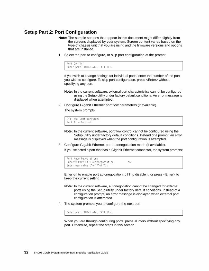
Setup Part 2: Port ConfigurationNote: The sample screens that appear in this document might differ slightly from
the screens displayed by your system. Screen content varies based on the type of chassis unit that you are using and the firmware versions and options that are installed.
1. Select the port to configure, or skip port configuration at the prompt:
If you wish to change settings for individual ports, enter the number of the port you wish to configure. To skip port configuration, press <Enter> without specifying any port.
Note: In the current software, external port characteristics cannot be configured using the Setup utility under factory default conditions. An error message is displayed when attempted.
2. Configure Gigabit Ethernet port flow parameters (if available).
The system prompts:
Note: In the current software, port flow control cannot be configured using the Setup utility under factory default conditions. Instead of a prompt, an error message is displayed when the port configuration is attempted.
3. Configure Gigabit Ethernet port autonegotiation mode (if available).
If you selected a port that has a Gigabit Ethernet connector, the system prompts:
Enter on to enable port autonegotiation, off to disable it, or press <Enter> to keep the current setting.
Note: In the current software, autonegotiation cannot be changed for external ports using the Setup utility under factory default conditions. Instead of a configuration prompt, an error message is displayed when external port configuration is attempted.
4. The system prompts you to configure the next port:
When you are through configuring ports, press <Enter> without specifying any port. Otherwise, repeat the steps in this section.
Port Config:Enter port (INTA1-A14, EXT1-10):
Gig Link Configuration:Port Flow Control:
Port Auto Negotiation:Current Port EXT1 autonegotiation: onEnter new value ["on"/"off"]:
Enter port (INTA1-A14, EXT1-10):

© Copyright IBM Corp. 2014 Chapter 3: Initial Setup 33
Setup Part 3: IP Configuration
The system prompts for IP parameters.
IP Interfaces
The Setup utility allows one optional IPv4 management interface and/or one optional IPv6 management interface to be configured on the SI4093. The IP address assigned to each interface provides the SI4093 with an IP presence on their respective management networks. The administrator can use the configurated IP addresses to connect to the SI4093 for remote configuration.
Note: IP management interfaces operate under VLAN 4095, which is reserved for management functions and cannot be used in attached data domains.
1. Select the IP interface to configure, or skip interface configuration at the prompt:
If you wish to configure an !Pv4 management interface, select interface 127. To configure an IPv6 management interface, select interface 126. To skip IP interface configuration, press <Enter> without typing an interface number and go to “Default Gateways” on page 35.
2. If configuring an IPv4 management interface (interface 127):
a. Enter the IP address in IPv4 dotted decimal notation:
To keep the current setting (if any is displayed), press <Enter>.
b. At the prompt, enter the IPv4 subnet mask in dotted decimal notation:
To keep the current setting (if any is displayed), press <Enter>.
c. At the prompt, enter the VLAN for the interface:
To keep the current setting, press <Enter>.
Note: In the current software, the IPv4 management interface VLAN cannot be changed using the Setup utility under factory default conditions. An error message is displayed when you attempt to change the setting.
d. At the prompt, enter y to enable the IP interface, or n to leave it disabled:
IP Config:
IP interfaces:Enter interface number: (125, 127)
Enter new IP address:
Enter new subnet mask:
Current VLAN: 4095Enter new VLAN [1-4095]:
Enable IP interface? [y/n]

34 SI4093 10Gb System Interconnect Module: Application Guide
3. If configuring an IPv6 management interface (interface 125):
a. Enter the IP address in IPv6 hexidecimal notation (see “IPv6 Address Format” on page 118):
To keep the current setting (if any is displayed), press <Enter>.
b. At the prompt, enter the IPv6 anycast address if desired:
To keep the current setting (if any is displayed), press <Enter>.
c. At the prompt, enter the IPv6 prefix length:
To keep the current setting (if any is displayed), press <Enter>.
d. At the prompt, enter the VLAN for the interface:
To keep the current setting, press <Enter>.
Note: In the current software, the IPv4 management interface VLAN cannot be changed using the Setup utility under factory default conditions. An error message is displayed when you attempt to change the setting.
e. At the prompt, enter y to enable the IP interface, or n to leave it disabled:
4. The system prompts you to configure another interface:
Repeat the steps in this section until all desired management interfaces have been configured. When all interfaces have been configured, press <Enter> without specifying any interface number.
Enter new IP address:
Enter anycast if <IPv6 address> is anycast|<CR>:
Enter new Prefix length [1-128]:
Current VLAN: 4095Enter new VLAN [1-4095]:
Enable IP interface? [y/n]
Enter interface number: (125, 127)

© Copyright IBM Corp. 2014 Chapter 3: Initial Setup 35
Default Gateways1. At the prompt, select an IP default gateway for configuration, or skip default
gateway configuration:
Enter the number for the IP default gateway to be configured. To skip default gateway configuration, press <Enter> without typing a gateway number and go to “Setup Part 4: Final Steps” on page 35.
Note: In the current software, default gateway 4 cannot be configured using the Setup utility under factory default conditions. An error message is displayed when gateway 4 is selected.
2. At the prompt, enter the IPv4 address for the selected default gateway:
Enter the IPv4 address in dotted decimal notation, or press <Enter> without specifying an address to accept the current setting.
3. At the prompt, enter y to enable the default gateway, or n to leave it disabled:
4. The system prompts you to configure another default gateway:
Repeat the steps in this section until all default gateways have been configured. When all default gateways have been configured, press <Enter> without specifying any number.
Setup Part 4: Final Steps1. When prompted, decide whether to restart Setup or continue to the final steps:
Enter y to restart the Setup utility from the beginning, or n to continue.
2. When prompted, decide whether you wish to review the configuration changes:
Enter y to review the changes made during this session of the Setup utility. Enter n to continue without reviewing the changes. We recommend that you review the changes.
IP default gateways:Enter default gateway number: (3, 4)
Current IP address: 0.0.0.0Enter new IP address:
Enable default gateway? [y/n]
Enter default gateway number: (3, 4)
Would you like to run from top again? [y/n]
Review the changes made? [y/n]

36 SI4093 10Gb System Interconnect Module: Application Guide
3. Next, decide whether to apply the changes at the prompt:
Enter y to apply the changes, or n to continue without applying. Changes are normally applied.
4. At the prompt, decide whether to make the changes permanent:
Enter y to save the changes to flash. Enter n to continue without saving the changes. Changes are normally saved at this point.
5. If you do not apply or save the changes, the system prompts whether to abort them:
Enter y to discard the changes. Enter n to return to the “Apply the changes?” prompt.
Optional Setup for Telnet SupportNote: This step is optional. Perform this procedure only if you are planning on
connecting to the SI4093 through a remote Telnet connection.
Telnet is disabled by default. To change the setting, use the following configuration command:
Apply the changes? [y/n]
Save changes to flash? [y/n]
Abort all changes? [y/n]
SIM# configure terminalSIM(config)# [no] access telnet enable

© Copyright IBM Corp. 2014 37
Chapter 4. Updating the System Software
The SI4093 software image is the executable code that directs system operation. A version of the image comes pre-installed on the device. As new versions of the image are released, you can upgrade the software running on your SI4093.
The typical upgrade process for the software image consists of the following steps:
• Determine the version of software currently installed on your system.
• Get the latest version of software available for your system.
• Load a new software image and boot image onto an FTP or TFTP server on your network.
• Transfer the new images to your SI4093.
• Specify the new software image as the one which will be loaded into SI4093 memory the next time a system reset occurs.
• Reset the SI4093.
Detailed instructions for this typical upgrade process are covered in the rest of this chapter.
Determining the Current Software Version
To determine the software version currently used on the system, enter the following CLI command:
The software version will be shown in the resulting display.
Getting the Latest SI4093 Software
To get the latest version of software supported for your SI4093, go to the following website:
http://www.ibm.com/systems/support
SIM# show boot

38 SI4093 10Gb System Interconnect Module: Application Guide
Loading New Software to Your SI4093
CAUTION:Although the standard software installation process as described in this section is all that is necessary in most cases, installing certain versions of N/OS requires additional, special steps to be taken prior to and/or after software installation. Check the Release Notes available for the specific version of the software you wish to install, and follow all applicable instructions. Failing to heed the full instructions in the Release Notes may cause unexpected behavior in the SI4093.
The SI4093 can store up to two different system software images (called image1 and image2) as well as special boot software (called boot). When you load new software, you must specify where it should be placed: either into image1, image2, or boot.
For example, if your active image is currently loaded into image1, you would probably load the new image software into image2. This lets you test the new software and reload the original active image (stored in image1), if needed.
CAUTION:When you upgrade the SI4093 software image, always load both the new boot image and the new software image before you reset the system. If you do not load a new boot image, your SI4093 might not boot properly (to recover, see “Recovering from a Failed Upgrade” on page 40).
To load a new software image to your SI4093, you will need the following:
• The image and boot software loaded on an FTP or TFTP server on your network.
Note: Be sure to download both the new boot file and the new image file.
• The hostname or IP address of the FTP or TFTP server
Note: The DNS parameters must be configured if specifying hostnames.
• The name of the new software image or boot file
When the software requirements are met, use the following procedure to download the new software to your SI4093:
1. In Privileged EXEC mode, enter the following command, specifying the method for loading the software (TFTP or FTP) and the SI4093 destination (image1, image2, or boot-image):
2. When prompted, enter the hostname or IP address of the FTP or TFTP server.
SIM# copy {tftp|ftp} {image1|image2|boot-image}
Address or name of remote host: <name or IP address>

© Copyright IBM Corp. 2014 Chapter 4: Updating the System Software 39
3. When prompted, enter the name of the new software file on the server.
The exact form of the name will vary by server. However, the file location is normally relative to the FTP or TFTP directory (for example, tftpboot).
4. If required by the FTP or TFTP server, enter the appropriate username and password.
5. The SI4093 will prompt you to confirm your request.
Once confirmed, the software will begin loading into the SI4093.
6. When loading is complete, use the following commands to enter Global Configuration mode and select which software image (image1 or image2) you want to run in system memory for the next reboot:
The system will then verify which image is set to be loaded at the next reset:
7. Reboot the SI4093 to run the new software:
The system prompts you to confirm your request. Once confirmed, the system will reboot to use the new software.
Source file name: <filename>
SIM# configure terminalSIM(config)# boot image {image1|image2}
Next boot will use switch software image1 instead of image2.
SIM(config)# reload

40 SI4093 10Gb System Interconnect Module: Application Guide
Recovering from a Failed Upgrade
The Boot Management menu allows you to perform fundamental device management operations, such as selecting which software image will be loaded, resetting the SI4093 to factory defaults, or recovering from a failed software download.
Use the following procedure to recover from a failed software upgrade.
1. Connect a PC to the serial Console port of the SI4093.
2. Open a terminal emulator program that supports XModem Download (for example, HyperTerminal, SecureCRT, PuTTY) and select the following port characteristics:
– Speed: 9600 bps
– Data Bits: 8
– Stop Bits: 1
– Parity: None
– Flow Control: None
3. To access the Boot Management menu, you must interrupt the boot process from the Console port. Boot the SI4093, and when the system begins displaying Memory Test progress (a series of dots), press <Shift B>.
The Boot Management menu will appear:
4. On the resulting menu, select 3 for Xmodem download. When you see the following message, change the port characteristics in your terminal emulation software to 115200 bps:
5. Press <Enter> to set the system into download accept mode. When the readiness meter displays (a series of “C” characters), start XModem on your terminal emulator.
Resetting the System ...
Memory Test ................................
Boot Management Menu1 - Change booting image2 - Change configuration block3 - Xmodem download4 - Exit
Please choose your menu option: 1Current boot image is 1. Enter image to boot: 1 or 2: 2Booting from image 2
## Switch baudrate to 115200 bps and press ENTER ...

© Copyright IBM Corp. 2014 Chapter 4: Updating the System Software 41
6. Select the Boot Image to download. The XModem initiates the file transfer. When the download is complete, a message similar to the following is displayed:
7. When you see the following message, change the port characteristics in your terminal emulation software to 9600 bps:
8. Press the Escape key (<Esc>) to re-display the Boot Management menu.
9. Select 3 to start a new XModem Download. When you see the following message, change the port characteristics in your terminal emulation software to 115200 bps:
10. Press <Enter> to continue the download.
yzModem - CRC mode, 62494(SOH)/0(STX)/0(CAN) packets, 6 retries
Extracting images ... Do *NOT* power cycle the switch.
**** VMLINUX ****
Un-Protected 10 sectors
Erasing Flash............. done
Writing to Flash.............done
Protected 10 sectors
**** RAMDISK ****
Un-Protected 44 sectors
Erasing Flash............................................... done
Writing to Flash...............................................done
Protected 44 sectors
**** BOOT CODE ****
Un-Protected 8 sectors
Erasing Flash........... done
Writing to Flash...........done
Protected 8 sectors
## Switch baudrate to 9600 bps and press ESC ...
## Switch baudrate to 115200 bps and press ENTER ...

42 SI4093 10Gb System Interconnect Module: Application Guide
11. Select the N/OS Image to download. The XModem initiates the file transfer. When the download is complete, a message similar to the following is displayed:
12. Select the image number to load the new image (1 or 2). It is recommended that you select 1. A message similar to the following is displayed:
13. When you see the following message, change the port characteristics in your terminal emulation software to 9600 bps:
14. Press the Escape key (<Esc>) to re-display the Boot Management menu.
15. Select 4 to exit and boot using the new image.
yzModem - CRC mode, 27186(SOH)/0(STX)/0(CAN) packets, 6 retries
Extracting images ... Do *NOT* power cycle the switch.
**** Switch OS ****
Please choose the Switch OS Image to upgrade [1|2|n] :
Switch OS Image 1 ...
Un-Protected 27 sectors
Erasing Flash.............................. done
Writing to Flash..............................done
Protected 27 sectors
## Switch baudrate to 9600 bps and press ESC ...

© Copyright IBM Corp. 2014 43
Chapter 5. System License Keys
License keys determine the number of available ports on the SI4093.
Basic License
The basic license is active by default on the SI4093. It provides the use of 24 ports as follows:
• Ports INTA1 through INTA14
Internal 1/10 Gbps Ethernet ports that connect to servers within the chassis.
• Ports EXT1 through EXT10
External 1/10 Gbps SFP+ Ethernet ports for uplink to the network.
All ports in the basic license are assigned to SPAR-1 by default. After initial start-up, the external ports are pre-configured by default to form a single, loop-free IEEE 802.1 Link Aggregation Group (LAG) that allows for plug-and-play operation. In this state, you can attach as many of the available uplink ports as required to meet application bandwidth requirements to the upstream device.
Optional Upgrade License 1
For expansion, upgrade license 1 provides up to 46 ports. In addition to all ports provided by the basic license, the following are available:
• Ports INTB1 through INTB14
Internal 1/10 Gbps Ethernet ports that connect to the servers within the chassis.
• Port EXT15 through EXT22
By default, each of the two external QSFP+ ports is configured for operation as four 10 Gbps Ethernet uplinks to the network using the appropriate system divider cables.
However, if high-bandwidth connections are preferred, each QSFP+ port can independently configured to operate in undivided 40 Gbps Ethernet mode (see “QSFP+ Ports” on page 97).
The extra ports provided by upgrade 1 are assigned to SPAR-2 by default. This isolates them from the SPAR-1 ports provided by the basic license, and helps ensure that newly attached domains maintain separation when the upgrade is activated.
As with the basic license, the external ports available with upgrade license 1 are initially grouped together into their own LAG.
Optional Upgrade License 2
Upgrade license 2 provides up to 64 ports. In addition to all ports provided by the basic license and upgrade license 1, the following are available:
• Ports INTC1 through INTC14
Internal 1/10 Gbps Ethernet ports that connect to the servers within the chassis.
• Port EXT11 through Port EXT14
External 1/10 Gbps SFP+ Ethernet ports for uplink to the network.

44 SI4093 10Gb System Interconnect Module: Application Guide
The extra ports provided by the upgrade are assigned to SPAR-3 by default. This isolates them from the SPAR-1 and SPAR-2 ports provided by the other licenses, and helps ensure that newly attached domains maintain separation when the upgrade is activated.
As with the other licenses, the external ports available with upgrade license 2 are initially grouped together into their own LAG.
Upgrade license 2 requires that upgrade license 1 be installed first.
Trial Licenses
Trial licenses are intended evaluation purposes. Like upgrade licenses, trial licenses allow you to increase the number of available ports. However, trial licenses expire after a predefined number of days.
Beginning ten days before the trial license expiration date, the SI4093 will begin to issue the following message in the system log:
If the trial license expires, all features enabled by the license will be disabled, system configuration files (active and backup) will be deleted, and the SI4093 will be reset to the factory-default settings.
To avoid expiration, you must either install an upgrade license to overwrite the trial license, or manually remove the trial license and reboot the SI4093.
Once a trial license is installed, it cannot be reused.
Obtaining Activation Keys
Upgrade or trial licenses can be acquired using the IBM System x Features on Demand (FoD) website:
http://www.ibm.com/systems/x/fod/
You can also use the website to review and manage licenses, and to obtain additional help. if required.
Note: An IBM ID and password are required to log into the FoD website. If you do not yet have an IBM ID, you can register at the website.
On the FoD website, obtain an Authorization Code for each desired license. You will need to provide the unique ID (UID) of the specific SI4093 where the key will be installed. The UID is the last 12 characters of the SI4093 serial number. This serial number is located on the Part Number (PN) label and is also displayed during successful login to the device.
Once your transaction is complete, the FoD website will provide an activation key file. Download the file and install it as directed in “Installing Activation Keys” on page 45.
The software demo license for Upgrade1 will expire in 10 days. The switch willautomatically reset to the factory configuration after the license expires. Pleasebackup your configuration or enter a valid license key so the configuration will notbe lost.

© Copyright IBM Corp. 2014 Chapter 5: System License Keys 45
Installing Activation Keys
Once FoD activation key files have been acquired, they must be installed on the SI4093. The example below depicts use of the SI4093 Command Line Interface (CLI), but other device interfaces (such as SNMP) may also be used.
When installing licenses, please note the following requirements:
• The SI4093 must be reset to activate any newly installed licenses.
• The 64 Port License (Upgrade 2) will not function unless the 46 Port License (Upgrade 1) is also present. If installing both upgrades at the same time, upload both keys prior to resetting the SI4093.
To install activation keys, complete the following steps:
1. Log in to the SI4093.
2. At the CLI prompt, enter the following commands:
3. Follow the prompts to enter the appropriate parameters, including the file transfer protocol and server parameters.
Note: Repeat the enakey command for any additional keys being installed.
4. Once the key file has been uploaded to the SI4093, reset the device to activate any newly installed licenses:
The system prompts you to confirm your request. Once confirmed, the system will reboot with the new licenses.
Transferring Activation Keys
Licenses keys are based on the unique SI4093 device serial number and are non-transferable.
In the event that the SI4093 must be replaced, a new activation key must be acquired and installed. When the replacement is handled through IBM Service and Support, your original license will be transferred to the serial number of the replacement unit and you will be provided a new license key.
SIM> enableSIM# configure terminalSIM(config)# software-keySIM(config)# enakey addr <server IP address> keyfile <key filename>
SIM(config)# reload

46 SI4093 10Gb System Interconnect Module: Application Guide

© Copyright IBM Corp. 2014 47
Part 2: Securing the SI4093

48 IBM Flex System Fabric SI4093 System Interconnect Module: Application Guide

© Copyright IBM Corp. 2014 49
Chapter 6. Administrative Security
This chapter discusses different methods of securing local and remote administration on the SI4093 10Gb System Interconnect Module (SI4093):
• “Changing the System Passwords” on page 49
• “Secure Shell and Secure Copy” on page 50
• “End User Access Control” on page 55
• “Protected Mode” on page 63
Changing the System Passwords
Access to the SI4093 command line interface is controlled through the use of a login. Once you are connected to the SI4093, you are prompted to enter a login name and its associated password. By default, three log-ins are available:
• The user
The user login has limited control of the SI4093. Through a user account, you can view system information and statistics, but you can’t make configuration changes.
The default username is: user
The default password is: user• The administrator
The administrator login has complete access to all menus, information, and configuration commands, including the ability to change both the user and administrator passwords.
The default username is: admin
The default password is: admin• An alternate administrator:
The default username is: USERID
The default password is: PASSW0RD (with a zero)
This admin-level account occupies end-user ID 1 (see “End User Access Control” on page 55).
It is recommended that you change the passwords after initial setup and as regularly as required under your network security policies.
This user password can be changed from the user account. The administrator account can change all passwords, as shown in the following procedure.
1. Log-in to the SI4093.
When prompted, enter the administrator username and password:
Note: If the administrator password has been unexpectedly changed and lost, call your technical support representative for help using the password fix-up mode.

50 SI4093 10Gb System Interconnect Module: Application Guide
2. Access the configuration mode:
The enable command initiates Privileged EXEC mode, and the configure terminal command readies the SI4093 for basic configuration. The system prompt changes to indicate the current command mode.
3. Set the new user password:
This command will prompt for the required information: the current administrator password, the new user password (up to 128 characters), and confirmation of the new user password.
4. Set the new administrator “admin” password:
This command will prompt for required information: current administrator password, new administrator password (up to 128 characters), and confirmation of the new administrator password.
5. Set the new alternate administrator “USERID” password:
This command will prompt for required information: current administrator password, new administrator password (up to 128 characters), and confirmation of the new administrator password.
Secure Shell and Secure Copy
Because using Telnet does not provide a secure connection for managing a SI4093, Secure Shell (SSH) and Secure Copy (SCP) features have been included for SI4093 management. SSH and SCP use secure tunnels to encrypt and secure messages between a remote administrator and the SI4093.
• SSH is a protocol that enables remote administrators to log securely into the SI4093 over a network to execute management commands. The SI4093 supports SSH version 2.0 and above.
By default, SSH is enabled on the SI4093.
• SCP is typically used to copy files securely from one device to another. SCP uses SSH for encryption of data on the network. On the SI4093, SCP is used to download and upload the system configuration via secure channels.
By default, SCP is disabled on the SI4093.
SIM> enableSIM# configure terminalSIM(config)#
SIM(config)# access user user-password
SIM(config)# access user administrator-password
SIM(config)# access user 1 password
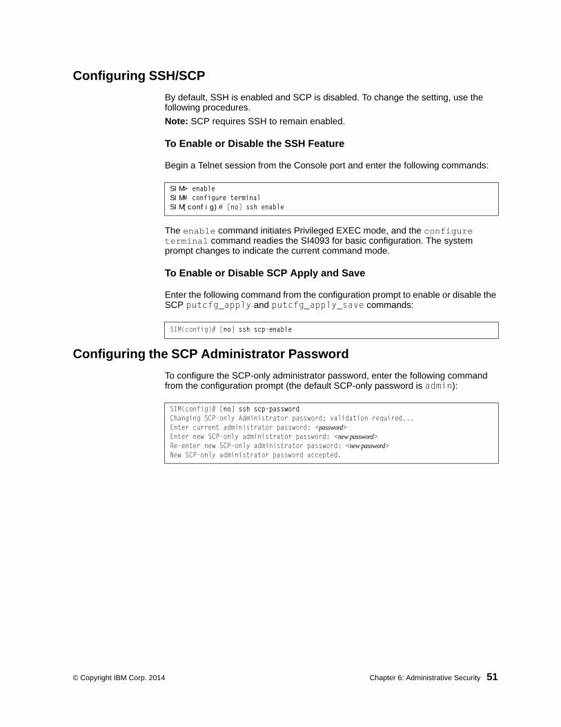
© Copyright IBM Corp. 2014 Chapter 6: Administrative Security 51
Configuring SSH/SCP
By default, SSH is enabled and SCP is disabled. To change the setting, use the following procedures.
Note: SCP requires SSH to remain enabled.
To Enable or Disable the SSH Feature
Begin a Telnet session from the Console port and enter the following commands:
The enable command initiates Privileged EXEC mode, and the configure terminal command readies the SI4093 for basic configuration. The system prompt changes to indicate the current command mode.
To Enable or Disable SCP Apply and Save
Enter the following command from the configuration prompt to enable or disable the SCP putcfg_apply and putcfg_apply_save commands:
Configuring the SCP Administrator Password
To configure the SCP-only administrator password, enter the following command from the configuration prompt (the default SCP-only password is admin):
SIM> enableSIM# configure terminalSIM(config)# [no] ssh enable
SIM(config)# [no] ssh scp-enable
SIM(config)# [no] ssh scp-passwordChanging SCP-only Administrator password; validation required...Enter current administrator password: <password>Enter new SCP-only administrator password: <new password>Re-enter new SCP-only administrator password: <new password>New SCP-only administrator password accepted.

52 SI4093 10Gb System Interconnect Module: Application Guide
Using SSH and SCP Client Commands
This section shows the format for using some common client commands.
To Log In to the SI4093 from the Client
Syntax:
Note: The -4 option (the default) specifies that an IPv4 address on the SI4093 will be used. The -6 option specifies IPv6.
Example:
To Copy the SI4093 System Configuration File to the SCP Host
Syntax:
Example:
To Load a SI4093 System Configuration File from the SCP Host
Syntax:
Example:
>> ssh [-4|-6] <SI4093 IP address>
-or->> ssh [-4|-6] <login name>@<SI4093 IP address>
>> ssh [email protected]
>> scp [-4|-6] <username>@<SI4093 IP address>:getcfg <local filename>
>> scp [email protected]:getcfg ad4.cfg
>> scp [-4|-6] <local filename> <username>@<SI4093 IP address>:putcfg
>> scp ad4.cfg [email protected]:putcfg

© Copyright IBM Corp. 2014 Chapter 6: Administrative Security 53
To Save the Configuration
When loading a configuration file to the SI4093, the commands in the file are automatically applied to the current configuration. However, the commands are not saved, and will be lost when the SI4093 is rebooted unless saved to the system’s FLASH memory. The appropriate commands may be entered using SCP.
Syntax:
Example:
The putcfg_apply_save command is usually preferred over putcfg because the SCP session is not in an interactive mode.
To Copy the SI4093 Software Image and Boot Files to the SCP Host
Syntax:
Example:
To Load SI4093 System Configuration Files from the SCP Host
Syntax:
Example:
>> scp [-4|-6] <local filename> <username>@<SI4093 IP address>:putcfg_apply_save
>> scp ad4.cfg [email protected]:putcfg_apply_save
>> scp [-4|-6] <username>@<SI4093 IP address>:getimg1 <local filename> >> scp [-4|-6] <username>@<SI4093 IP address>:getimg2 <local filename> >> scp [-4|-6] <username>@<SI4093 IP address>:getboot <local filename>
>> scp [email protected]:getimg1 6.1.0_os.img
>> scp [-4|-6] <local filename> <username>@<SI4093 IP address>:putimg1>> scp [-4|-6] <local filename> <username>@<SI4093 IP address>:putimg2>> scp [-4|-6] <local filename> <username>@<SI4093 IP address>:putboot
>> scp 6.1.0_os.img [email protected]:putimg1

54 SI4093 10Gb System Interconnect Module: Application Guide
SSH and SCP Encryption of Management Messages
The following encryption and authentication methods are supported for SSH and SCP:
• Server Host Authentication: 1024-bit RSA host key
• Key Exchange: diffie-hellman-group1-sha1, diffie-hellman-group14-sha1
• Encryption: 3des-cbc, aes128-cbc, aes128-ctr, arcfour, arcfour128, arcfour256, blowfish-cbc, rijndael128-cbc
• MAC: hmac-md5, hmac-md5-96, hmac-sha1, hmac-sha1-96
• User Authentication: Local password authentication, LDAP, RADIUS, TACACS+
Generating the RSA Host Key for SSH Access
To support the SSH feature, an RSA host key is required. The host key is 1024 bits and is used to identify the SI4093.
When SSH is first enabled, the SI4093 automatically generates the RSA host key and stores it in FLASH memory.
To manually create an RSA host key, enter the following command via the SI4093 Console port (the command is not available via external Telnet connection)
When the SI4093 reboots, it will retrieve the host key from the FLASH memory.
Note: The SI4093 will perform only one session of key/cipher generation at a time. Thus, an SSH/SCP client will not be able to log in if the system is performing key generation at that time. Also, key generation will fail if an SSH/SCP client is logging in at that time.
SSH/SCP Integration with RADIUS AuthenticationSSH/SCP is integrated with RADIUS authentication. After the RADIUS server is enabled on the SI4093, all subsequent SSH authentication requests will be redirected to the specified RADIUS servers for authentication. The redirection is transparent to the SSH clients.
SSH/SCP Integration with TACACS+ AuthenticationSSH/SCP is integrated with TACACS+ authentication. After the TACACS+ server is enabled on the SI4093, all subsequent SSH authentication requests will be redirected to the specified TACACS+ servers for authentication. The redirection is transparent to the SSH clients.
SIM(config)# ssh generate-host-key

© Copyright IBM Corp. 2014 Chapter 6: Administrative Security 55
Secure FTP
The SI4093 supports Secure FTP (SFTP). SFTP uses Secure Shell (SSH) to transfer files. SFTP encrypts both commands and data, and prevents passwords and sensitive information from being transmitted openly over the network. The following command is an example of SFTP support on the SI4093:
This command copies a software file from the SFTP server to the SI4093.
End User Access ControlIBM Networking OS allows an administrator to define end user accounts that permit end users to perform operation tasks via the SI4093 CLI commands. Once end user accounts are configured and enabled, the SI4093 requires username/password authentication.
For example, an administrator can assign a user, who can then log into the SI4093 and perform operational commands (effective only until the next SI4093 reboot).
Considerations for Configuring End User Accounts
• A maximum of 10 user IDs are supported on the SI4093.
• IBM Networking OS supports end-user account for the Console port, Telnet, and SSH version 2 (or above) access to the SI4093.
• If RADIUS authentication is used, the user password on the Radius server will override the user password on the SI4093. Also note that the password change command modifies only the user password on the SI4093 and has no effect on the user password on the Radius server. Radius authentication and user password cannot be used concurrently to access the SI4093.
• Passwords can be up to 128 characters in length for TACACS, RADIUS, Telnet, SSH, and Console port access.
Strong Passwords
The administrator can require use of Strong Passwords for users to access the SI4093. Strong Passwords enhance security because they make password guessing more difficult.
The following rules apply when Strong Passwords are enabled:
• Minimum length: 8 characters; maximum length: 14 characters
• Must contain at least one uppercase alphabet
• Must contain at least one lowercase alphabet
• Must contain at least one number
• Must contain at least one special character:
Supported special characters: ! “ # % & ‘ ( ) ; < = >> ? [ \ ] * + , - . / : ^ _ { | } ~
When strong password is enabled, users can still access the SI4093 using the old password but will be advised to change to a strong password while attempting to log in.
SIM# copy sftp {image1|image2|boot-image} [mgt-port|extm-port]

56 SI4093 10Gb System Interconnect Module: Application Guide
Strong password requirement can be enabled using the following command:
The administrator can choose the number of days allowed before each password expires. When a strong password expires, the user is allowed to log in one last time (last time) to change the password. A warning provides advance notice for users to change the password.
User Access Control Menu
The end-user access control commands allow you to configure end-user accounts.
Up to 10 user IDs can be configured. Use the following commands to define any user name and set the user password at the resulting prompts:
Note: User 1 is pre-configured for administrator-level access, with a login name of USERID and password of PASSW0RD (with a zero). This user ID cannot be disabled, nor can the name or access level be changed. Only the password can be changed.
Defining a User’s Access Level
The end user is by default assigned to the user access level (also known as class of service, or CoS). CoS for all user accounts have global access to all resources except for User CoS, which has access to view only resources that the user owns. For more information, see Table 7 on page 67.
To change the user’s level, select one of the following options:
Note: The administrator access level for User 1 cannot be changed.
Validating a User’s Configuration
Enabling or Disabling a User
An end user account must be enabled before the SI4093 recognizes and permits login under the account. Once enabled, the SI4093 requires any user to enter both username and password.
Note: User 1 cannot be disabled.
SIM # access user strong-password enable
SIM(config)# access user 2 name <1-64 characters>SIM(config)# access user 2 password
Changing user1 password; validation required:Enter current admin password: <current administrator password>Enter new user1 password: <new user password of up to 128 characters>Re-enter new user1 password: <new user password>New user1 password accepted.
SIM(config)# access user 2 level {user|operator|administrator}
SIM# show access user uid 2
SIM(config)# [no] access user 2 enable

© Copyright IBM Corp. 2014 Chapter 6: Administrative Security 57
Listing Current Users
The following command displays defined user accounts and whether or not each user is currently logged into the SI4093.
Logging In to an End User Account
Once an end user account is configured and enabled, the user can login to the SI4093 by using the username/password combination. The degree of SI4093 access is determined by the Class of Service established for the end user account.
SIM# show access user
Usernames:user - enabled - offlineoper - disabled - offlineadmin - Always Enabled - online 1 session.
Current User ID table:1: name USERID , ena, cos admin , password valid, offline

58 SI4093 10Gb System Interconnect Module: Application Guide
Boot Strict Mode
The implementations specified in this section are compliant with National Institute of Standards and Technology (NIST) Special Publication (SP) 800-131A.
The SI4093 can operate in two boot modes:
• Compatibility mode (default): This is the default boot mode. This mode may use algorithms and key lengths that are not allowed or acceptable by the NIST SP 800-131A specification. This mode is useful in maintaining compatibility with previous releases and in environments that have lesser data security requirements.
• Strict mode: Encryption algorithms, protocols, and key lengths in strict mode are compliant with the NIST SP 800-131A specification.
When in boot strict mode, the SI4093 uses Secure Sockets Layer (SSL)/Transport Layer Security (TLS) 1.2 protocols to ensure confidentiality of the data to and from the SI4093.
By default, Telnet, and SNMPv1 and SNMPv2 are disabled on the SI4093. In strict mode, you cannot enable these protocols if the security policy on the SI4093 is set to “secure.” In compatibility mode, these protocols can be enabled, if required.
Before enabling strict mode, ensure the following:
• All connected SI4093 devices and IBM switches must run IBM Networking OS 7.8.
• The supported protocol versions and cryptographic cipher suites between clients and servers must be compatible. For example: if using SSH to connect to the SI4093, ensure that the SSH client supports SSHv2 and a strong cipher suite that is compliant with the NIST standard.
• A new self-signed certificate must be generated for the SI4093 (SIM(config)# access https generate-certificate). The new certificate must be generated using a 2048-bit RSA key and SHA-256 digest.
• Protocols that are not NIST SP 800-131A compliant must be disabled or remain unused.
• Only SSHv2 or higher may be used.
• Save the current configuration, if any, in a location external to the SI4093. When the SI4093 reboots, both the startup and running configuration are lost.
• Only protocols/algorithms compliant with the NIST SP 800-131A specification are used or enabled on the SI4093. Please see the NIST SP 800-131A publication for details. Table 4 on page 59 lists the acceptable protocols and algorithms.

© Copyright IBM Corp. 2014 Chapter 6: Administrative Security 59
Table 4. Acceptable Protocols and Algorithms
Protocol and Function
Strict Mode Algorithm Compatibility Mode Algorithm
CertificateGeneration
RSA-2048
SHA-256
RSA 2048
SHA 256
CertificateAcceptance
RSA 2048 or higher
SHA 224 or higher
RSA
SHA, SHA2
LDAP LDAP does not comply with NIST SP 800-131A specification. When in strict mode, LDAP is dis-abled. However, it can be enabled, if required.
Acceptable
RADIUS RADIUS does not comply with NIST SP 800-131A specification. When in strict mode, RADIUS is disabled. However, it can be enabled, if required.
Acceptable
Random Number Generator
NIST SP 800-90A AES CTR DRBG NIST SP 800-90A AES CTR DRBG
Secure NTP Secure NTP does not comply with NIST SP 800-131A specification. When in strict mode, secure NTP is disabled. However, it can be enabled, if required.
Acceptable
SLP SHA-256 or higher
RSA/DSA 2048 or higher
SNMP SNMPv3 only
AES-128-CFB-128/SHA1
Note: Following algorithms are acceptable if you choose to support old SNMPv3 factory default users:
AES-128-CFB/SHA1DES/MD5AES-128-CFB-128/SHA1
SNMPv1, SNMPv2, SNMPv3
DES/MD5, AES-128-CFB-128/SHA1
SSH/SFTP
Host Key SSH-RSA SSH-RSA
Key Exchange ECDH-SHA2-NISTP521ECDH-SHA2-NISTP384ECDH-SHA2-NISTP256ECDH-SHA2-NISTP224RSA2048-SHA256DIFFIE-HELLMAN-GROUP-EXCHANGE-SHA256DIFFIE-HELLMAN-GROUP-EXCHANGE-SHA1
ECDH-SHA2-NISTP521ECDH-SHA2-NISTP384ECDH-SHA2-NISTP256ECDH-SHA2-NISTP224ECDH-SHA2-NISTP192RSA2048-SHA256RSA1024-SHA1DIFFIE-HELLMAN-GROUP-EXCHANGE-SHA256DIFFIE-HELLMAN-GROUP-EXCHANGE-SHA1DIFFIE-HELLMAN-GROUP14-SHA1DIFFIE-HELLMAN-GROUP1-SHA1

60 SI4093 10Gb System Interconnect Module: Application Guide
Encryption AES128-CTRAES128-CBC3DES-CBC
AES128-CTRAES128-CBCRIJNDAEL128-CBCBLOWFISH-CBC3DES-CBCARCFOUR256ARCFOUR128ARCFOUR
MAC HMAC-SHA1HMAC-SHA1-96
HMAC-SHA1HMAC-SHA1-96HMAC-MD5HMAC-MD5-96
TACACS+ TACACS+ does not comply with NIST SP 800-131A specification. When in strict mode, TACACS+ is disabled. However, it can be enabled, if required.
Acceptable
Table 4. Acceptable Protocols and Algorithms
Protocol and Function
Strict Mode Algorithm Compatibility Mode Algorithm
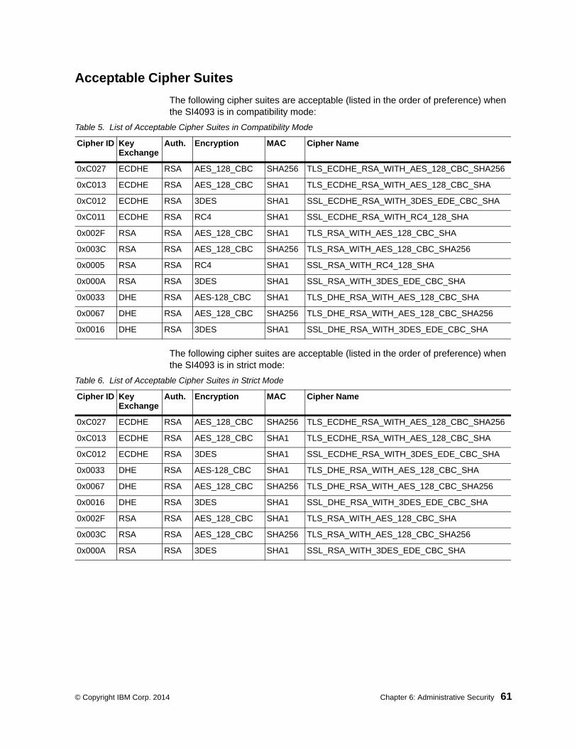
© Copyright IBM Corp. 2014 Chapter 6: Administrative Security 61
Acceptable Cipher Suites
The following cipher suites are acceptable (listed in the order of preference) when the SI4093 is in compatibility mode:
The following cipher suites are acceptable (listed in the order of preference) when the SI4093 is in strict mode:
Table 5. List of Acceptable Cipher Suites in Compatibility Mode
Cipher ID Key Exchange
Auth. Encryption MAC Cipher Name
0xC027 ECDHE RSA AES_128_CBC SHA256 TLS_ECDHE_RSA_WITH_AES_128_CBC_SHA256
0xC013 ECDHE RSA AES_128_CBC SHA1 TLS_ECDHE_RSA_WITH_AES_128_CBC_SHA
0xC012 ECDHE RSA 3DES SHA1 SSL_ECDHE_RSA_WITH_3DES_EDE_CBC_SHA
0xC011 ECDHE RSA RC4 SHA1 SSL_ECDHE_RSA_WITH_RC4_128_SHA
0x002F RSA RSA AES_128_CBC SHA1 TLS_RSA_WITH_AES_128_CBC_SHA
0x003C RSA RSA AES_128_CBC SHA256 TLS_RSA_WITH_AES_128_CBC_SHA256
0x0005 RSA RSA RC4 SHA1 SSL_RSA_WITH_RC4_128_SHA
0x000A RSA RSA 3DES SHA1 SSL_RSA_WITH_3DES_EDE_CBC_SHA
0x0033 DHE RSA AES-128_CBC SHA1 TLS_DHE_RSA_WITH_AES_128_CBC_SHA
0x0067 DHE RSA AES_128_CBC SHA256 TLS_DHE_RSA_WITH_AES_128_CBC_SHA256
0x0016 DHE RSA 3DES SHA1 SSL_DHE_RSA_WITH_3DES_EDE_CBC_SHA
Table 6. List of Acceptable Cipher Suites in Strict Mode
Cipher ID Key Exchange
Auth. Encryption MAC Cipher Name
0xC027 ECDHE RSA AES_128_CBC SHA256 TLS_ECDHE_RSA_WITH_AES_128_CBC_SHA256
0xC013 ECDHE RSA AES_128_CBC SHA1 TLS_ECDHE_RSA_WITH_AES_128_CBC_SHA
0xC012 ECDHE RSA 3DES SHA1 SSL_ECDHE_RSA_WITH_3DES_EDE_CBC_SHA
0x0033 DHE RSA AES-128_CBC SHA1 TLS_DHE_RSA_WITH_AES_128_CBC_SHA
0x0067 DHE RSA AES_128_CBC SHA256 TLS_DHE_RSA_WITH_AES_128_CBC_SHA256
0x0016 DHE RSA 3DES SHA1 SSL_DHE_RSA_WITH_3DES_EDE_CBC_SHA
0x002F RSA RSA AES_128_CBC SHA1 TLS_RSA_WITH_AES_128_CBC_SHA
0x003C RSA RSA AES_128_CBC SHA256 TLS_RSA_WITH_AES_128_CBC_SHA256
0x000A RSA RSA 3DES SHA1 SSL_RSA_WITH_3DES_EDE_CBC_SHA

62 SI4093 10Gb System Interconnect Module: Application Guide
Configuring Strict Mode
To change the SI4093 mode to or from boot strict mode, use the following Privileged EXEC Configuration mode command:
When strict mode is enabled, you will see the following message:
For SNMPv3 default users, see “SNMP Version 3” on page 169.
When strict mode is disabled, the following message is displayed:
You must reboot the SI4093 for the boot strict mode enable/disable to take effect.
Boot Strict Mode Limitations
Consider the following limitation and restrictions if you need to operate the SI4093 in boot strict mode:
• Power ITEs and High-Availability features do not comply with NIST SP 800-131A specification.
• The SI4093 will not discover Platform agents/Common agents that are not in strict mode.
• Limited functions of the SI4093 managing Windows will be available.
SIM(config)# [no] boot strict enable
Warning, security strict mode limits the cryptographic algorithms used by secure protocols on this switch. Please see the documentation for full details, and verify that peer devices support acceptable algorithms before enabling this mode. The mode change will take effect after reloading the switch and the configuration will be wiped during the reload. System will enter security strict mode with default factory configuration at next boot up.
Do you want SNMPV3 support old default users in strict mode (y/n)?
Warning, disabling security strict mode. The mode change will take effect after reloading the switch.

© Copyright IBM Corp. 2014 Chapter 6: Administrative Security 63
Protected ModeProtected Mode settings allow the SI4093 administrator to block the management module from making configuration changes that affect system operation. The SI4093 retains control over those functions.
The following management module functions are disabled when Protected Mode is turned on:
• External Ports: Enabled/Disabled
• External management over all ports: Enabled/Disabled
• Restore Factory Defaults
• New Static IP Configuration
In this release, configuration of the functions listed above are restricted to the local SI4093 when you turn Protected Mode on. In future releases, individual control over each function may be added.
Note: Before you turn Protected Mode on, make sure that external management (Telnet) access to one of the IP interfaces on the SI4093 is enabled.
Use the following Privileged EXEC Configuration mode command to turn Protected Mode on:
If you lose access to the SI4093 through the external ports, use the Console port to connect directly to the SI4093, and configure an IP interface with Telnet access to reestablish access.
SIM(config)# protected-mode enable

64 SI4093 10Gb System Interconnect Module: Application Guide

© Copyright IBM Corp. 2014 65
Chapter 7. Authentication & Authorization Protocols
Secure SI4093 management is needed for environments that perform significant management functions across the Internet. The following are some of the functions for secured IPv4 management and device access:
• “RADIUS Authentication and Authorization” on page 65• “TACACS+ Authentication” on page 69• “LDAP Authentication and Authorization” on page 73
Note: IBM Networking OS 7.8 does not support IPv6 for RADIUS, TACACS+ or LDAP.
RADIUS Authentication and Authorization
The SI4093 supports the RADIUS (Remote Authentication Dial-in User Service) method to authenticate and authorize remote administrators for managing the SI4093. This method is based on a client/server model. The Remote Access Server (RAS)—the SI4093—is a client to the back-end database server. A remote user (the remote administrator) interacts only with the RAS, not the back-end server and database.
RADIUS authentication consists of the following components:
• A protocol with a frame format that utilizes UDP over IP (based on RFC 2138 and 2866)
• A centralized server that stores all the user authorization information• A client (in this case, the SI4093 is the client)
The SI4093—acting as the RADIUS client—communicates to the RADIUS server to authenticate and authorize a remote administrator using the protocol definitions specified in RFC 2138 and 2866. Transactions between the client and the RADIUS server are authenticated using a shared key that is not sent over the network. In addition, the remote administrator passwords are sent encrypted between the RADIUS client (the SI4093) and the back-end RADIUS server.
How RADIUS Authentication Works
1. Remote administrator connects to the SI4093 and provides user name and password.
2. Using Authentication/Authorization protocol, the SI4093 sends request to authentication server.
3. Authentication server checks the request against the user ID database.
4. Using RADIUS protocol, the authentication server instructs the SI4093 to grant or deny administrative access.

66 SI4093 10Gb System Interconnect Module: Application Guide
Configuring RADIUS on the SI4093
Use the following procedure to configure Radius authentication on your SI4093.
1. Configure the IPv4 addresses of the Primary and Secondary RADIUS servers, and enable RADIUS authentication.
2. Configure the RADIUS secret.
Statement 21:
CAUTIONIf you configure the RADIUS secret using any method other than through the Console port, the secret may be transmitted over the network as clear text.
3. If desired, you may change the default UDP port number used to listen to RADIUS.
The well-known port for RADIUS is 1645.
4. Configure the number retry attempts for contacting the RADIUS server, and the timeout period.
RADIUS Authentication Features in IBM Networking OS
IBM Networking OS supports the following RADIUS authentication features:
• Supports RADIUS client on the SI4093, based on the protocol definitions in RFC 2138 and RFC 2866.
• Allows a RADIUS secret password of up to 32 characters.
• Supports secondary authentication server so that when the primary authentication server is unreachable, the SI4093 can send client authentication requests to the secondary authentication server. Use the following command to show the currently active RADIUS authentication server:
SIM(config)# radius-server primary-host 10.10.1.1SIM(config)# radius-server secondary-host 10.10.1.2SIM(config)# radius-server enable
SIM(config)# radius-server primary-host 10.10.1.1 key <1-32 character secret>SIM(config)# radius-server secondary-host 10.10.1.2 key <1-32 character secret>
SIM(config)# radius-server port <UDP port number>
SIM(config)# radius-server retransmit 3SIM(config)# radius-server timeout 5
SIM# show radius-server

© Copyright IBM Corp. 2014 Chapter 7: Authentication & Authorization Protocols 67
• Supports user-configurable RADIUS server retry and time-out values:
– Time-out value = 1-10 seconds
– Retries = 1-3
The SI4093 will time out if it does not receive a response from the RADIUS server within 1-10 seconds. The SI4093 automatically retries connecting to the RADIUS server 1-3 times before it declares the server down.
• Supports user-configurable RADIUS application port. The default is UDP port 1645. UDP port 1812, based on RFC 2138, is also supported.
• Allows network administrator to define privileges for one or more specific users to access the SI4093 at the RADIUS user database.
User Accounts
The user accounts listed in Table 7 can be defined in the RADIUS server dictionary file.
Table 7. User Access Levels
Account Description and Tasks Performed Default Password
Level: User
Name: user
The User has no direct responsibility for SI4093 management. They can view all system status information and statistics but cannot make any configuration changes to the system.
user
Level: Operator
Name: oper
In addition to User capabilities, the Operator has limited system management access, including the ability to make temporary, operational configuration changes to some SI4093 features, and to reset SI4093 ports (other than management ports).
oper
Level: Admin
Name: admin
The super-user Administrator has complete access to all menus, information, and configuration commands on the SI4093, including the ability to change both the user and administrator passwords.
admin
Level: Admin
Name: USERID
An alternate administrator account. This admin-level account occupies end-user ID 1 (see “End User Access Control” on page 55).
PASSW0RD(with a zero)

68 SI4093 10Gb System Interconnect Module: Application Guide
RADIUS Attributes for IBM Networking OS User Privileges
When the user logs in, the SI4093 authenticates his/her level of access by sending the RADIUS access request, that is, the client authentication request, to the RADIUS authentication server.
If the remote user is successfully authenticated by the authentication server, the SI4093 will verify the privileges of the remote user and authorize the appropriate access.
All user privileges, other than those assigned to the Administrator, have to be defined in the RADIUS dictionary. RADIUS attribute 6 which is built into all RADIUS servers defines the administrator. The file name of the dictionary is RADIUS vendor-dependent. The following RADIUS attributes are defined for IBM Networking OS user privileges levels:
RADIUS Backdoor
The administrator has a number of options to allow backdoor access via Telnet and SSH. When enabled, the backdoor allows the administrator to log in using the noradius user name and the regular SI4093 administrator password. Two options are available:
• Secure backdoor permits remote backdoor access only when the RADIUS server cannot be reached. This option is disabled by default.
• Regular backdoor permits remote backdoor access at any time, regardless of the RADIUS server status. This option also is disabled by default.
Note: The RADIUS backdoor is always available from the local Console port, regardless of remote backdoor settings.
Remote backdoor options can be enabled or disabled using the following CLI commands:
Table 8. IBM Networking OS-proprietary Attributes for RADIUS
User Level/Name User-Service-Type Value
User / user Vendor-supplied 255
Operator / oper Vendor-supplied 252
Administrator / admin Vendor-supplied 6
Administrator / USERID Vendor-supplied 6
SIM(config)# [no] radius-server secure-backdoor (Backdoor only when server is down)
SIM(config)# [no] radius-server backdoor (Backdoor always available)

© Copyright IBM Corp. 2014 Chapter 7: Authentication & Authorization Protocols 69
TACACS+ Authentication
IBM Networking OS supports authentication, authorization, and accounting with networks using the Cisco Systems TACACS+ protocol. The SI4093 functions as the Network Access Server (NAS) by interacting with the remote client and initiating authentication and authorization sessions with the TACACS+ access server. The remote user is defined as someone requiring management access to the SI4093 either through a data or management port.
TACACS+ offers the following advantages over RADIUS:
• TACACS+ uses TCP-based connection-oriented transport; whereas RADIUS is UDP-based. TCP offers a connection-oriented transport, while UDP offers best-effort delivery. RADIUS requires additional programmable variables such as re-transmit attempts and time-outs to compensate for best-effort transport, but it lacks the level of built-in support that a TCP transport offers.
• TACACS+ offers full packet encryption whereas RADIUS offers password-only encryption in authentication requests.
• TACACS+ separates authentication, authorization and accounting.
How TACACS+ Authentication Works
TACACS+ works much in the same way as RADIUS authentication as described on page 65.
1. Remote administrator connects to the SI4093 and provides user name and password.
2. Using Authentication/Authorization protocol, the SI4093 sends request to authentication server.
3. Authentication server checks the request against the user ID database.
4. Using TACACS+ protocol, the authentication server instructs the SI4093 to grant or deny administrative access.
During a session, if additional authorization checking is needed, the SI4093 checks with a TACACS+ server to determine if the user is granted permission to use a particular command.

70 SI4093 10Gb System Interconnect Module: Application Guide
TACACS+ Authentication Features in IBM Networking OS
Authentication is the action of determining the identity of a user, and is generally done when the user first attempts to log in to a device or gain access to its services. IBM Networking OS supports ASCII inbound login to the device. PAP, CHAP and ARAP login methods, TACACS+ change password requests, and one-time password authentication are not supported.
Authorization
Authorization is the action of determining a user’s privileges on the device, and usually takes place after authentication.
The default mapping between TACACS+ authorization levels and IBM Networking OS management access levels is shown in Table 9. The authorization levels listed in this table must be defined on the TACACS+ server.
Alternate mapping between TACACS+ authorization levels and IBM Networking OS management access levels is shown in Table 10. Use the following command to use the alternate TACACS+ authorization levels:
If the remote user is successfully authenticated by the authentication server, the SI4093 verifies the privileges of the remote user and authorizes the appropriate access.
Table 9. Default TACACS+ Authorization Levels
IBM Networking OS Account Name TACACS+ Level
user 0
oper 3
admin 6
USERID (administrator) 6
SIM(config)# tacacs-server privilege-mapping
Table 10. Alternate TACACS+ Authorization Levels
IBM Networking OS Account Name TACACS+ Level
user 0–1
oper 6–8
admin 14–15
USERID (administrator) 14–15

© Copyright IBM Corp. 2014 Chapter 7: Authentication & Authorization Protocols 71
Backdoor
The administrator has a number of options to allow backdoor access via Telnet and SSH. When enabled, the backdoor allows the administrator to log in using the notacacs user name and the regular SI4093 administrator password. Two options are available:
• Secure backdoor permits remote backdoor access only when the TACACS+ server cannot be reached. This option is disabled by default.
• Regular backdoor permits remote backdoor access at any time, regardless of the TACACS+ server status. This option also is disabled by default.
Note: The TACACS+ backdoor is always available from the local Console port, regardless of remote backdoor settings.
Remote backdoor options can be enabled or disabled using the following CLI commands:
Accounting
Accounting is the action of recording a user's activities on the device for the purposes of billing and/or security. It follows the authentication and authorization actions. If the authentication and authorization is not performed via TACACS+, there are no TACACS+ accounting messages sent out.
You can use TACACS+ to record and track software login access, configuration changes, and interactive commands.
The SI4093 supports the following TACACS+ accounting attributes:
• protocol (console/telnet/ssh)
• start_time• stop_time• elapsed_time• disc-cause
Command Authorization and Logging
When TACACS+ Command Authorization is enabled, N/OS configuration commands are sent to the TACACS+ server for authorization. Use the following command to enable TACACS+ Command Authorization:
When TACACS+ Command Logging is enabled, N/OS configuration commands are logged on the TACACS+ server. Use the following command to enable TACACS+ Command Logging:
SIM(config)# [no] tacacs-server secure-backdoor (Backdoor only when server is down)
SIM(config)# [no] tacacs-server backdoor (Backdoor always available)
SIM(config)# tacacs-server command-authorization
SIM(config)# tacacs-server command-logging

72 SI4093 10Gb System Interconnect Module: Application Guide
The following examples illustrate the format of IBM Networking OS commands sent to the TACACS+ server:
Configuring TACACS+ Authentication on the SI4093
1. Configure the IPv4 addresses of the Primary and Secondary TACACS+ servers, and enable TACACS authentication.
2. Configure the TACACS+ secret and second secret.
Statement 21:
CAUTIONIf you configure the TACACS+ secret using any method other than a direct Console port connection, the secret may be transmitted over the network as clear text.
3. If desired, you may change the default TCP port number used to listen to TACACS+. The well-known port for TACACS+ is 49.
4. Configure the number of retry attempts, and the timeout period.
authorization request, cmd=shell, cmd-arg=interface ipaccounting request, cmd=shell, cmd-arg=interface ipauthorization request, cmd=shell, cmd-arg=enableaccounting request, cmd=shell, cmd-arg=enable
SIM(config)# tacacs-server primary-host 10.10.1.1SIM(config)# tacacs-server secondary-host 10.10.1.2SIM(config)# tacacs-server enable
SIM(config)# tacacs-server primary-host 10.10.1.1 key <1-32 character secret>SIM(config)# tacacs-server secondary-host 10.10.1.2 key <1-32 character secret>
SIM(config)# tacacs-server port <TCP port number>
SIM(config)# tacacs-server retransmit 3SIM(config)# tacacs-server timeout 5

© Copyright IBM Corp. 2014 Chapter 7: Authentication & Authorization Protocols 73
LDAP Authentication and Authorization
IBM Networking OS supports the LDAP (Lightweight Directory Access Protocol) method to authenticate and authorize remote administrators to manage the SI4093. LDAP is based on a client/server model. The SI4093 acts as a client to the LDAP server. A remote user (the remote administrator) interacts only with the SI4093, not the back-end server and database.
LDAP authentication consists of the following components:
• A protocol with a frame format that utilizes TCP over IP• A centralized server that stores all the user authorization information• A client (in this case, the SI4093 is the client)
Each entry in the LDAP server is referenced by its Distinguished Name (DN). The DN consists of the user-account name concatenated with the LDAP domain name. If the user-account name is John, the following is an example DN:
uid=John,ou=people,dc=domain,dc=com
If the remote user is successfully authenticated by the authentication server, the SI4093 verifies the privileges of the remote user and authorizes the appropriate access.
LDAP Backdoor
The administrator has can allow backdoor access via Telnet and SSH. When enabled, the backdoor allows the administrator to log in using the noldap user name and the regular SI4093 administrator password at any time. This option is disabled by default.
Note: The LDAP backdoor is always available from the local Console port, regardless of the remote backdoor setting.
Remote backdoor can be enabled or disabled using the following CLI commands:
Configuring the LDAP Server
SI4093 user groups and user accounts must reside within the same domain. On the LDAP server, configure the domain to include SI4093 user groups and user accounts, as follows:
• User Accounts:
Use the uid attribute to define each individual user account.
• User Groups:
Use the members attribute in the groupOfNames object class to create the user groups. The first word of the common name for each user group must be equal to the user group names defined in the SI4093, as follows:
– admin– oper– user
SIM(config)# [no] ldap-server backdoor (Backdoor always available)

74 SI4093 10Gb System Interconnect Module: Application Guide
Configuring LDAP Authentication on the SI40931. Turn LDAP authentication on, then configure the Primary and Secondary LDAP
servers.
2. Configure the domain name.
3. If desired, you may change the default TCP port number used to listen to LDAP.
The well-known port for LDAP is 389.
4. Configure the number of retry attempts for contacting the LDAP server, and the timeout period.
SIM(config)# ldap-server enableSIM(config)# ldap-server primary-host 10.10.1.1SIM(config)# ldap-server secondary-host 10.10.1.2
SIM(config)# ldap-server domain <ou=people,dc=my-domain,dc=com>
SIM(config)# ldap-server port <1-65000>
SIM(config)# ldap-server retransmit 3SIM(config)# ldap-server timeout 10
© Copyright IBM Corp. 2014 75
Chapter 8. Access Control Lists
Access Control Lists (ACLs) are filters that permit or deny traffic for security purposes. They can also be used with QoS to classify and segment traffic in order to provide different levels of service to different traffic types. Each filter defines the conditions that must match for inclusion in the filter, and also the actions that are performed when a match is made.
IBM Networking OS 7.8 supports the following ACLs:
• IPv4 ACLs
Up to 256 ACLs are supported for networks that use IPv4 addressing. IPv4 ACLs are configured using the following CLI command:
• IPv6 ACLs
Up to 128 ACLs are supported for networks that use IPv6 addressing. IPv6 ACLs are configured using the following CLI command:
SIM(config)# access-control list <IPv4 ACL number> ?
SIM(config)# access-control list6 <IPv6 ACL number> ?

76 SI4093 10Gb System Interconnect Module: Application Guide
Summary of Packet ClassifiersACLs allow you to classify packets according to a variety of content in the packet header (such as the source address, destination address, source port number, destination port number, and others). Once classified, packet flows can be identified for more processing.
Regular ACLs allow you to classify packets based on the following packet attributes:
• Ethernet header options (for regular ACLs only)– Source MAC address
– Destination MAC address
– VLAN number and mask
– Ethernet type (ARP, IPv4, MPLS, RARP, etc.)
– Ethernet Priority (the IEEE 802.1p Priority)
• IPv4 header options (for regular ACLs only)– Source IPv4 address and subnet mask
– Destination IPv4 address and subnet mask
– Type of Service value
– IP protocol number or name as shown in Table 11:
Table 11. Well-Known Protocol Types
Number Protocol Name
1261789112
icmpigmptcpudpospfvrrp

© Copyright IBM Corp. 2014 Chapter 8: Access Control Lists 77
• TCP/UDP header options (for all ACLs)
– TCP/UDP application source port as shown in Table 12.
– TCP/UDP application destination port and mask as shown in Table 12.
– TCP/UDP flag value as shown in Table 13.
• Packet format (for regular ACLs only)
– Ethernet format (eth2, SNAP, LLC)
– Ethernet tagging format
– IP format (IPv4)
• Egress port packets (for all ACLs)
Table 12. Well-Known Application Ports
PortTCP/UDPApplication Port
TCP/UDPApplication Port
TCP/UDPApplication
2021222325374243536970
ftp-dataftpsshtelnetsmtptimenamewhoisdomaintftpgopher
7980
109110111119123143144161162
fingerhttppop2pop3sunrpcnntpntpimapnewssnmpsnmptrap
179194220389443520554
1645/181218131985
bgpircimap3ldaphttpsriprtspRadiusRadius Accountinghsrp
Table 13. Well-Known TCP flag values
Flag Value
URGACKPSHRSTSYNFIN
0x00200x00100x00080x00040x00020x0001

78 SI4093 10Gb System Interconnect Module: Application Guide
Summary of ACL Actions
Once classified using ACLs, the identified packet flows can be processed differently. For each ACL, an action can be assigned. The action determines how the SI4093 treats packets that match the classifiers assigned to the ACL. SI4093 ACL actions include the following:
• Pass or Drop the packet
• Re-mark the packet with a new DiffServ Code Point (DSCP)
• Re-mark the 802.1p field
• Set the COS queue
Assigning Individual ACLs to a Port
Once you configure an ACL, you must assign the ACL to the appropriate ports. Each port can accept multiple ACLs, and each ACL can be applied for multiple ports. ACLs can be assigned individually, or in groups.
To assign an individual ACLs to a port, use the following IP Interface Mode commands:
When multiple ACLs are assigned to a port, higher-priority ACLs are considered first, and their action takes precedence over lower-priority ACLs. ACL order of precedence is discussed in the next section.
To create and assign ACLs in groups, see “ACL Groups” on page 79.
ACL Order of Precedence
When multiple ACLs are assigned to a port, they are evaluated in numeric sequence, based on the ACL number. Lower-numbered ACLs take precedence over higher-numbered ACLs. For example, ACL 1 (if assigned to the port) is evaluated first and has top priority.
If multiple ACLs match the port traffic, only the action of the one with the lowest ACL number is applied. The others are ignored.
The ACL number is the sole factor in determining ACL order of precedence. The order in which ACLs are applied to a port does not affect the order of precedence, nor does the ACL Group number (see “ACL Groups” on page 79), the order in which an ACL is assigned to an ACL Group, or the order in which the ACL Group is assigned to a port.
If no assigned ACL matches the port traffic, no ACL action is applied.
SIM(config)# interface port <port>SIM(config-ip)# access-control list <IPv4 ACL number>
SIM(config-ip)# access-control list6 <IPv6 ACL number>

© Copyright IBM Corp. 2014 Chapter 8: Access Control Lists 79
ACL GroupsTo assist in organizing multiple ACLs and assigning them to ports, you can place ACLs into ACL Groups, thereby defining complex traffic profiles. ACLs and ACL Groups can then be assigned on a per-port basis. Any specific ACL can be assigned to multiple ACL Groups, and any ACL or ACL Group can be assigned to multiple ports. If, as part of multiple ACL Groups, a specific ACL is assigned to a port multiple times, only one instance is used. The redundant entries are ignored.
• Individual ACLsThe SI4093 supports up to 256 ACLs. Each ACL defines one filter rule for matching traffic criteria. Each filter rule can also include an action (permit or deny the packet). For example:
• Access Control List GroupsAn Access Control List Group (ACL Group) is a collection of ACLs. For example:
ACL Groups organize ACLs into traffic profiles that can be more easily assigned to ports. The SI4093 supports up to 256 ACL Groups.
Note: ACL Groups are used for convenience in assigning multiple ACLs to ports. ACL Groups have no effect on the order in which ACLs are applied (see “ACL Order of Precedence” on page 78). All ACLs assigned to the port (whether individually assigned or part of an ACL Group) are considered as individual ACLs for the purposes of determining their order of precedence.
ACL 1:VLAN = 1SIP = 10.10.10.1 (255.255.255.0)Action = permit
ACL Group 1
ACL 1:VLAN = 1SIP = 10.10.10.1 (255.255.255.0)Action = permit
ACL 2:VLAN = 2SIP = 10.10.10.2 (255.255.255.0)Action = deny
ACL 3:Priority = 7DIP = 10.10.10.3 (255.255.255.0)Action = permit

80 SI4093 10Gb System Interconnect Module: Application Guide
Assigning ACL Groups to a Port
To assign an ACL Group to a port, use the following commands:
ACL Metering and Re-Marking
You can define a profile for the aggregate traffic flowing through the SI4093 by configuring a QoS meter (if desired) and assigning ACLs to ports.
Note: When you add ACLs to a port, make sure they are ordered correctly in terms of precedence (see “ACL Order of Precedence” on page 78).
Actions taken by an ACL are called In-Profile actions. You can configure additional In-Profile and Out-of-Profile actions on a port. Data traffic can be metered, and re-marked to ensure that the traffic flow provides certain levels of service in terms of bandwidth for different types of network traffic.
Metering
QoS metering provides different levels of service to data streams through user-configurable parameters. A meter is used to measure the traffic stream against a traffic profile which you create. Thus, creating meters yields In-Profile and Out-of-Profile traffic for each ACL, as follows:
• In-Profile–If there is no meter configured or if the packet conforms to the meter, the packet is classified as In-Profile.
• Out-of-Profile–If a meter is configured and the packet does not conform to the meter (exceeds the committed rate or maximum burst rate of the meter), the packet is classified as Out-of-Profile.
Using meters, you set a Committed Rate in Kbps (1000 bits per second in each Kbps). All traffic within this Committed Rate is In-Profile. Additionally, you can set a Maximum Burst Size that specifies an allowed data burst larger than the Committed Rate for a brief period. These parameters define the In-Profile traffic.
Meters keep the sorted packets within certain parameters. You can configure a meter on an ACL, and perform actions on metered traffic, such as packet re-marking.
Re-Marking
Re-marking allows for the treatment of packets to be reset based on new network specifications or desired levels of service. You can configure the ACL to re-mark a packet as follows:
• Change the DSCP value of a packet, used to specify the service level that traffic should receive.
• Change the 802.1p priority of a packet.
SIM(config)# interface port <port>SIM(config-ip)# access-control group <ACL group number>

© Copyright IBM Corp. 2014 Chapter 8: Access Control Lists 81
ACL Port Mirroring
For regular ACLs, packets that match an ACL on a specific port can be mirrored to another SI4093 port for network diagnosis and monitoring.
The source port for the mirrored packets cannot be a portchannel, but may be a member of a portchannel.
The destination port to which packets are mirrored must be a physical port.
If the ACL has an action (permit, drop, etc.) assigned, it cannot be used to mirror packets for that ACL.
Use the following command to add mirroring to an ACL:
The ACL must be also assigned to it target ports as usual (see “Assigning Individual ACLs to a Port” on page 78, or “Assigning ACL Groups to a Port” on page 80).
Viewing ACL Statistics
ACL statistics display how many packets have “hit” (matched) each ACL. Use ACL statistics to check filter performance or to debug the ACL filter configuration.
You must enable statistics for each ACL that you wish to monitor:
ACL Configuration Examples
ACL Example 1
Use this configuration to block traffic to a specific host. All traffic that ingresses on port EXT1 is denied if it is destined for the host at IP address 100.10.1.1
1. Configure an Access Control List.
2. Add ACL 1 to port EXT1.
SIM(config)# access-control list <ACL number> mirror port <destination port>
SIM(config)# access-control list <ACL number> statistics
SIM(config)# access-control list 1 ipv4 destination-ip-address 100.10.1.1SIM(config)# access-control list 1 action deny
SIM(config)# interface port ext1SIM(config-if)# access-control list 1SIM(config-if)# exit

82 SI4093 10Gb System Interconnect Module: Application Guide
ACL Example 2
Use this configuration to block traffic from a network destined for a specific host address. All traffic that ingresses in port EXT2 with source IP from class 100.10.1.0/24 and destination IP 200.20.2.2 is denied.
1. Configure an Access Control List.
2. Add ACL 2 to port EXT2.
ACL Example 3
This configuration blocks traffic from a network that is destined for a specific egress port. All traffic that ingresses port EXT1 from the network 100.10.1.0/24 and is destined for port 3 is denied.
1. Configure an Access Control List.
2. Add ACL 4 to port EXT1.
SIM(config)# access-control list 2 ipv4 source-ip-address 100.10.1.0 255.255.255.0
SIM(config)# access-control list 2 ipv4 destination-ip-address 200.20.2.2 255.255.255.255
SIM(config)# access-control list 1 action deny
SIM(config)# interface port ext2SIM(config-if)# access-control list 2SIM(config-if)# exit
SIM(config)# access-control list 4 ipv4 source-ip-address 100.10.1.0 255.255.255.0
SIM(config)# access-control list 4 egress-port 3SIM(config)# access-control list 4 action deny
SIM(config)# interface port ext1SIM(config-if)# access-control list 4SIM(config-if)# exit

© Copyright IBM Corp. 2014 83
Part 3: Basic Features

84 IBM Flex System Fabric SI4093 System Interconnect Module: Application Guide

© Copyright IBM Corp. 2014 Chapter 9: Switch Partitions 85
Chapter 9. Switch Partitions
SPAR Overview
The SI4093 uses Switch Partition (SPAR) technology to facilitate the enforcement of multi-tenancy traffic segregation and security applications.
SPAR allows you to divide the SI4093 into up to eight different traffic zones, or partitions. Each SPAR represents a separate segment of the device’s data plane hardware. Traffic in a given SPAR is not shared with other SPARs on the same device: the traffic in each SPAR remains entirely segregated from other SPARs for the entire duration of its transit through the SI4093.
Figure 4. Basic Switch Partitions on the SI4093
As shown in Figure 4, each SPAR may be connected to its upstream network through separate L2/L3 routing or switching devices (recommended). Alternately, SPARs may be connected to the upstream network through a shared L2/L3 device with additional configuration.
By default, SI4093 ports are assigned to a specific SPAR based on the active system license keys (see “System License Keys” on page 43). Under the basic license, internal ports INTA1 through INTA14 and external ports EXT1 through EXT10 are available, and all are grouped into SPAR-1.
Each SPAR must include one or more internal server ports and one or more external uplink ports. However, if multiple external ports are to be included in a particular SPAR, they must first be configured as a Link Aggregation Group (LAG), thus operating together as a single logical port connected to the same upstream network entity. Any given SPAR cannot include multiple, independent (non-LAG) uplink ports.
Each internal or external port can be a member of only one SPAR at any given time. Because the SI4093 does not permit any SPAR to include multiple non-LAG uplink ports, the possibility of creating a broadcast loop is eliminated.
As part of the default Layer 2 Failover settings (see page 157), at least one uplink connection must be operational in order for the internal server ports to remain operational. This avoids situations where an internal server path is active but has no corresponding path to the external domains.
IBM Flex Chassis
SI4093Server 1
Server 2
Server 3
Server 4
Server 5SPAR-2
SPAR-1
Client ANetwork
Internet
Client BNetwork
...
LAGs
UpstreamNetworks
L2/L3 Switches
Router

86 SI4093 10Gb System Interconnect Module: Application Guide
Configuring SPARs requires the following basic tasks:
1. Group the desired ports into a SPAR.
2. Set the SPAR mode: transparent mode or VLAN-aware mode.
3. Disable FDB learning on uplinks, if required.
4. Set the SPAR’s default VLAN, if required.
These steps are described in detail in the remaining sections of this chapter.
SPAR Port Membership
Default SPAR Ports
Each internal or external port can be a member of only one SPAR at any given time. By default, all available ports are automatically assigned to a SPAR in order to allow plug-and-play operation. The default SPAR configuration depends on which system license keys are installed (see “System License Keys” on page 43), and are summarized as follows:
• SPAR-1
Defined automatically by factory default at all license levels:
– Internal ports INTA1–INTA10
– External ports EXT1–EXT10 in LAG 65 with LACP admin key 1000
– Uses default VLAN 4081 (reserved)
• SPAR-2
Defined automatically at license upgrades 1 and 2:
– Internal ports INTB1–INTB14
– External ports EXT15–EXT22 in LAG 66 with LACP admin key 1001
– Uses default VLAN 4082 (reserved)
• SPAR-3
Defined automatically at license upgrade 2 only:
– Internal ports INTC1–INTC14
– External ports EXT11–EXT14 in LAG 67 with LACP admin key 1002
– Uses default VLAN 4083 (reserved)
Regardless of the system license level, up to eight SPARs are available. You can reconfigure the port membership list for any SPAR, including default SPARs, to include any combination of ports available under the installed license: ports are not restricted to their default SPARs.

© Copyright IBM Corp. 2014 Chapter 9: Switch Partitions 87
Configuring SPAR Ports
Use the following commands in Privileged EXEC Configuration Mode to set port membership for any SPAR:
These commands relate as follows:
• The spar command selects the target SPAR for configuration.
• The domain default member command specifies the desired internal ports. At least one internal port must be specified.
• The uplink command specifies either an individual external uplink port, or a LAG consisting of multiple ports, identified by the admin key or portchannel ID.
When defining SPAR membership, if any of the desired ports is already a member of an existing SPAR, you must first remove those ports from their old SPAR. Likewise, if a desired external port is part of an LAG used on an existing SPAR, you must also remove the desired ports from their old LAG.
For example, to create SPAR-4 using ports INTA1, INTA2, EXT1, and EXT2 (which are part of SPAR-1 by default), use the following commands:
1. Select the contributor SPAR and remove the desired ports:
In this case, remove internal ports INTA1 and INTA2, and clear the external uplink. The entire uplink must be cleared because ports EXT1 and EXT2 are part of a LAG on the SPAR and cannot be removed independently of their LAG associates.
2. Remove the desired external ports from their old LAG, if any:
3. Repair SPAR-1 by returning the remainder of its external port LAG:
SIM(config)# spar <SPAR number (1-8)>SIM(config-spar)# domain default member <internal port, list, or range>SIM(config-spar)# uplink {port <external port>|portchannel <1-64>|adminkey <1-65535>}SIM(config-spar)# exit
SIM(config)# spar 1SIM(config-spar)# no domain default member inta1,inta2SIM(config-spar)# no uplink portSIM(config-spar)# exit
SIM(config)# interface port ext1-ext2SIM(config-if)# default lacpSIM(config-if)# exit
SIM(config)# spar 1SIM(config-spar)# uplink adminkey 1000SIM(config-spar)# exit

88 SI4093 10Gb System Interconnect Module: Application Guide
4. Place all desired external ports for the new SPAR into a new LAG:
Note: Multiple external ports cannot be added to a SPAR unless they are members of the same LAG. If only one external port is needed for the SPAR, no new LAG is required and this step can be omitted.
5. Assign the desired ports and enable SPAR-4:
Note: In this case, the LAG consisting of multiple external ports is added. If a single external port is preferred, the uplink port <external port> command would be used.
6. You can confirm the resulting configuration using the show running-config and show lacp information commands.
SIM(config)# portchannel 68 lacp key 500 suspend-individualSIM(config)# interface port ext1-ext2SIM(config-if)# lacp key 500SIM(config-if)# lacp mode activeSIM(config-if)# exit
SIM(config)# spar 4SIM(config-spar)# domain default member inta1,inta2SIM(config-spar)# uplink adminkey 500SIM(config-spar)# enableSIM(config-spar)# exit

© Copyright IBM Corp. 2014 Chapter 9: Switch Partitions 89
SPAR Modes
Each SPAR can operate either in transparent mode (the default) or in advanced VLAN-aware mode.
Transparent SPARs
By default, all available SPARs operate in transparent mode. With minimal initial configuration, this allows the SI4093 to be used as a plug-and-play device, suitable for low-touch, unmanaged environments. This facilitates quick installation and setup of chassis server modules in many deployments.
Transparent operation assumes the SI4093 is attached to a pre-configured upstream switch. In this topology, any configuration required for Layer 2 VLANs, FCoE, or IP routing is performed in the upstream network devices, or in the chassis server modules, or both. The SI4093 provides connectivity between the devices, but is transparent to the network and storage streams.
Transparent mode supports both IEEE 802.1 VLAN tagged and untagged frames without additional configuration.
Transparent SPARs are not aware of server VLANs. Each transparent SPAR operates as a single broadcast domain. Broadcast, multicast and unknown unicast traffic is delivered to all servers attached to the SPAR, regardless of their individual VLAN participation.
Any traffic from the servers that is not specifically destined for another internal server on the SPAR will be forwarded on the SPAR uplink. Outbound multicast traffic that originates from an internal server in the SPAR will be forwarded to all internal servers in the SPAR in addition to the SPAR uplink. Inbound multicast traffic received over the SPAR uplink will be forwarded to all servers in the SPAR.
Servers belonging to different SPARs cannot communicate directly through the SI4093, regardless of their VLAN membership. Instead, they must connect through their upstream devices.
Although transparent mode is used by default for each SPAR, the mode can be manually set using the following Privileged EXEC Configuration Mode commands:
When the SPAR mode is set as passthrough (transparent mode), any prior settings for VLAN-aware mode on the SPAR, such as local VLAN/port associations, are cleared.
SIM(config)# spar <SPAR number (1-8)>SIM(config-spar)# domain mode passthroughSIM(config-spar)# exit

90 SI4093 10Gb System Interconnect Module: Application Guide
VLAN-Aware SPARs
Optionally, each SPAR can be independently configured to operate in VLAN-aware mode.
For any SPAR operating in VLAN-aware mode, multiple IEEE 802.1 VLAN groups are supported. This provides an additional level of Layer 2 traffic partitioning within the SPAR where VLAN separation must be enforced within the SPAR. This differs from the default transparent mode in which VLAN broadcasts are received by all servers in the SPAR regardless of their VLAN participation. VLAN-aware mode is useful in topologies where multitenancy occurs within the SPAR.
VLAN-aware mode supports up to 256 VLANs per SPAR.
Configuring VLAN-Aware Mode
Use the following commands in Privileged EXEC Configuration Mode to configure VLAN-aware mode for any SPAR:
These commands relate as follows:
• The spar command selects the target SPAR for configuration.
• The domain mode local command specifies VLAN-aware mode for the SPAR.
• The various domain local commands specify a VLAN ID and its member ports for one of up to 256 VLAN domains available for the SPAR.
In the following example, VLAN-aware mode is configured for an existing SPAR, assumed to be previously defined with ports INTA9–INTA14. The example shows the addition of three enforced VLAN domains using the following Privileged EXEC Configuration Mode commands:
1. Select the SPAR.
2. Specify the domain mode as local for VLAN-aware operation.
3. Configure the local VLAN domains and their member ports.
SIM(config)# spar <SPAR number (1-8)>SIM(config-spar)# domain mode localSIM(config-spar)# domain local <domain index (1-256)> vlan <VLAN ID (2-4094)>SIM(config-spar)# domain local <domain index (1-256)> member <internal port, list, or range>SIM(config-spar)# domain local <domain index (1-256)> enableSIM(config-spar)# exit
SIM(config)# spar 5
SIM(config-spar)# domain mode local
SIM(config-spar)# domain local 1 vlan 10SIM(config-spar)# domain local 1 member inta9-inta10SIM(config-spar)# domain local 1 enableSIM(config-spar)# domain local 2 vlan 20SIM(config-spar)# domain local 2 member inta11-inta12SIM(config-spar)# domain local 2 enableSIM(config-spar)# domain local 3 vlan 30SIM(config-spar)# domain local 3 member inta13-inta14SIM(config-spar)# domain local 3 enable

© Copyright IBM Corp. 2014 Chapter 9: Switch Partitions 91
4. Exit the SPAR configuration mode.
Disabling FDB Learning on Uplinks
The recommended SPAR configurations are as follows:
• Transparent SPARs.
• VLAN-aware SPARs whose servers have no VLANs in common with other VLAN-aware SPARs on the SI4093.
• VLAN-aware SPARs whose servers may have VLANs in common with other VLAN-aware SPARs on the SI4093, and where the affected SPARs are connected to different upstream networks.
It is not recommended to connect more than one VLAN-aware SPAR to the same upstream network if servers on those SPARs use one or more of the same VLANs.
In that scenario, traffic sent by an upstream server on a VLAN that is configured on multiple SPARs will be delivered to the servers on each SPAR via their respective uplink. But because the SI4093 uses a shared forwarding table (rather than one per-SPAR), the forwarding entry for the upstream server appears only once, pointing to the uplink for only one of the SPARs. This can lead to scenarios where traffic originating from some SPARs is not properly delivered to the upstream server. In such circumstances, it may be necessary to disable address learning on the affected uplinks.
The Host setting addresses this issue. When Host is enabled, address learning is disabled on uplink ports for all VLAN-aware SPARs, and traffic originating from the SI4093 for all unknown destinations in each VLAN-aware SPARs (including traffic to upstream destinations) will be forwarded to each SPAR’s uplink. This setting should only be used when the conditions described above apply.
To enable or disable uplink learning globally for all VLAN-aware SPARs on the SI4093, use the following command in Privileged EXEC Configuration Mode:
SIM(config-spar)# exit
SIM(config)# [no] spar-global host-mode enable

92 SI4093 10Gb System Interconnect Module: Application Guide
SPAR Default VLANs
Every SPAR, whether operating in transparent mode or VLAN-aware mode, is assigned a unique VLAN ID. This identifier is used for internal SI4093 purposes. SPAR uses the same pool of VLAN IDs available for other applications, from VLAN 2 to VLAN 4094 (default VLAN 1 and management VLAN 4095 are reserved).
The VLAN assigned to each SPAR must be unique. It cannot be used for any other application. Similarly, any VLAN used by another application cannot be assigned as the SPAR default VLAN.
Initial SPAR default VLAN configurations are based on the installed license keys (see “System License Keys” on page 43) as follows:
• SPAR-1 is assigned VLAN 4081 by default at all license levels.
• SPAR-2 is assigned VLAN 4082 by default, at license upgrades 1 and 2.
• SPAR-3 is assigned VLAN 4083 by default, at license upgrade 2.
The default VLAN can be changed using the following Privileged EXEC Configuration Mode commands:
SPAR RestrictionsThe following SPAR restrictions apply to other SI4093 features:
• When creating LAGs (static or LACP trunks) on the SI4093, you cannot include any ports that currently belong to an existing SPAR or to any other LAG. To create a LAG, ports must first be released from any associated SPARs and LAGs.
• ACLs defined on the SI4093 can be used for SPAR ports. However, an ACL cannot be shared across SPAR ports if:
– An exit port is used as a filtering criteria and the exit port does not belong to the same SPAR as the port on which the ACL is applied.
– A monitor port is used as a filtering criteria, and the monitor port does not belong to the same SPAR as the mirrored port and is not defined on the default switch.
These ACL restrictions apply to all ACLs defined in an ACL group.
• Layer 2 failover features can be configured on SPAR ports for manual monitoring when all ports defined within the trigger belong to the same SPAR.
• Before using the FIP snooping feature, you must manually disable FIP snooping for internal and external ports where any of the following conditions apply:
– Disable for all transparent SPAR ports.
– Disable for ports where FCoE traffic is not desired.
– Disable for ports where transparent FCoE is acceptable.
SIM(config)# spar <SPAR number (1-8)>SIM(config-spar)# domain default vlan <VLAN ID (2-4094)>SIM(config-spar)# exit

© Copyright IBM Corp. 2014 Chapter 9: Switch Partitions 93
• The following features are not supported in SPARs (XPAR only):
– ACL VLAN Maps
– UFP
– VMready
– EVB
– IGMP
– Static Multicast ARP
– Hot Links
Example Configurations
Quick-Deployment SPAR Example
This example assumes an unmanaged environment with the default transparent SPAR for quick-deployment plug-and-play purposes. The topology is that of Figure 5.
Figure 5. Basic SI4093 Topology
1. Prepare the system environment.
In this deployment, servers and upstream L2/L3 switches must be installed and configured as desired, including any VLAN, routing, and FCoE features.
2. Install the SI4093 devices.
Two SI4093 devices are installed in the IBM Flex chassis: one in I/O Bay 1 and 2. Installation is performed according to the product User’s Guide.
3. Initialize the SI4093 devices
– System access and initial setup for each installed SI4093 are performed as described in “Administrative Access” on page 21, “Initial Setup” on page 29.
– Default passwords are changed as described in “Administrative Security” on page 49.
4. Connect each SI4093 device to its corresponding upstream switch.
By default, external ports EXT1 through EXT10 are activated on each SI4093 under the basic system license, and automatically configured in a LAG on SPAR-1. On each SI4093, connect two or more activated external ports to its upstream switch, depending on your bandwidth and redundancy requirements, and configure the ports on the upstream device for LAG operation.
DataNetwork
Storage AreaNetwork
IBM L2/L3 SwitchesIBM Flex Chassis
LAGs
Server 1 SI4093
SI4093
Server 2
Server 3
Server 14
...

94 SI4093 10Gb System Interconnect Module: Application Guide
5. Set the default VLAN ID on each SI4093, if necessary.
By default, the VLAN ID for SPAR-1 is 4081. If this VLAN is in use on your network for a different purpose, specify an unused VLAN for use with SPAR-1. For example:
6. Converged Enhanced Ethernet (CEE) with transparent Fibre-Channel over Ethernet (FCoE) is globally enabled by default, reserving lossless bandwidth for SAN traffic that uses QoS priority 3. If FCoE is not required, or if QoS priority 3 traffic is used for a different purpose, turn CEE off:
Note: Transparent FCoE does not install or enforce Fibre-Channel ACLs (FIP Snooping is disabled). For extended FCoE options, see “Fibre Channel over Ethernet” on page 125.
Transparent SPAR Example
This example includes configuration of a new SPAR (SPAR-4) in transparent mode. SPAR-4 will include member ports INTA1 and INTA2, and an external uplink LAG comprised of ports EXT1 and EXT2.
1. Because the desired ports are already in use by SPAR-1 by default, you must first release the desired ports:
The entire uplink must be cleared because ports EXT1 and EXT2 are part of a default LAG on SPAR-1 and cannot be removed independently of their LAG associates.
2. Move all desired external ports for the new SPAR into a new LAG:
Note: Multiple external ports cannot be added to a SPAR unless they are members of the same LAG. If only one external port is needed for the new SPAR, no new LAG is required: instead the old LAG must be cleared using the default lacp command.
3. Repair SPAR-1 by returning the remainder of its external port LAG:
SIM(config)# spar 1SIM(config-spar)# domain default vlan 400SIM(config-spar)# exit
SIM(config)# no cee enable
SIM(config)# spar 1SIM(config-spar)# no domain default member inta1,inta2SIM(config-spar)# no uplink portSIM(config-spar)# exit
SIM(config)# portchannel 68 lacp key 500 suspend-individualSIM(config)# interface port ext1-ext2SIM(config-if)# lacp key 500SIM(config-if)# lacp mode activeSIM(config-if)# exit
SIM(config)# spar 1SIM(config-spar)# uplink adminkey 1000SIM(config-spar)# exit

© Copyright IBM Corp. 2014 Chapter 9: Switch Partitions 95
4. Assign the desired ports to the new SPAR:
Note: In this case, the LAG consisting of multiple external ports is added. If a single external port is preferred, the uplink port <external port> command would be used.
5. Specify the domain mode as passthrough for transparent SPAR operation.
Note: Transparent mode is the default for all SPARs. If the mode has not previously been changed, you can omit this step.
6. Configure the default VLAN ID, if required.
The VLAN assigned to each SPAR must be unique. It cannot be used for any other application. Similarly, any VLAN used by another application cannot be assigned to a SPAR.
7. Enable the new SPAR and exit SPAR configuration mode:
8. You can confirm the resulting configuration using the show running-config command.
VLAN-Aware SPAR Example
This example describes configuration of SPAR-5 for VLAN-aware mode.
1. Create SPAR-5:
2. Configure the SPAR default VLAN and add member ports.
In this example, the SPAR is configured for VLAN 4085, with internal ports INTA9–INTA14. and a single external port as the uplink. To specify a LAG as the uplink the uplink portchannel or uplink adminkey commands could be used.
SIM(config)# spar 4SIM(config-spar)# domain default member inta1,inta2SIM(config-spar)# uplink adminkey 500
SIM(config-spar)# domain mode passthrough
SIM(config-spar)# domain default vlan 421
SIM(config-spar)# enableSIM(config-spar)# exit
SIM(config)# spar 5
SIM(config-spar)# domain default vlan 4085SIM(config-spar)# domain default member inta9-inta14SIM(config-spar)# uplink port ext3

96 SI4093 10Gb System Interconnect Module: Application Guide
Note: When defining SPAR ports, if any of the desired ports is already a member of an existing SPAR, you must first remove those ports from their old SPAR. Likewise, if a desired external port is part of an LAG, you must also remove the desired ports from their old LAG prior to assigning them as a SPAR uplink, or as part of a LAG being assigned as a SPAR uplink.
3. Specify the domain mode as local for VLAN-aware operation.
4. Configure local VLAN domains and their member ports.
5. Enable SPAR-5.
6. Exit the SPAR configuration mode.
SIM(config-spar)# domain mode local
SIM(config-spar)# domain local 1 vlan 10SIM(config-spar)# domain local 1 member inta9-inta10SIM(config-spar)# domain local 1 enableSIM(config-spar)# domain local 2 vlan 20SIM(config-spar)# domain local 2 member inta11-inta12SIM(config-spar)# domain local 2 enableSIM(config-spar)# domain local 3 vlan 30SIM(config-spar)# domain local 3 member inta13-inta14SIM(config-spar)# domain local 3 enable
SIM(config-spar)# enable
SIM(config-spar)# exit

© Copyright IBM Corp. 2014 97
Chapter 10. QSFP+ Ports
QSFP+ ports are available with optional upgrade license 1. The QSFP+ ports support both 10GbE and 40GbE, as shown in Table 14.
Table 14. QSFP+ Port Numbering
The following procedure allows you to change the QSFP+ port mode.
1. Display the current port mode for the QSFP+ ports.
2. Change the port mode to 40GbE. Select the physical port number.
3. Verify the change.
4. Reset the system.
5. Remove the configured port from QSFP+ mode to reset the ports to 10GbE mode
Physical Port Number 40GbE mode 10GbE mode
Port EXT15 Port EXT15 Ports EXT15-EXT18
Port EXT19 Port EXT19 Ports EXT19-EXT22
SIMconfig)# show boot qsfp-port-modes
QSFP ports booted configuration: Port EXT15, EXT16, EXT17, EXT18 - 10G Mode Port EXT19, EXT20, EXT21, EXT22 - 10G Mode
QSFP ports saved configuration: Port EXT15, EXT16, EXT17, EXT18 - 10G Mode Port EXT19, EXT20, EXT21, EXT22 - 10G Mode
SIM(config)# boot qsfp-40Gports EXT19
SIMconfig)# show boot qsfp-port-modes
QSFP ports booted configuration: Port EXT15, EXT16, EXT17, EXT18 - 10G Mode Port EXT19, EXT20, EXT21, EXT22 - 10G Mode
QSFP ports saved configuration: Port EXT15, EXT16, EXT17, EXT18 - 10G Mode Port EXT19 - 40G Mode
SIM(config)# reload
SIM(config)# no boot qsfp-40Gports <port number or a range of ports>

98 SI4093 10Gb System Interconnect Module: Application Guide

© Copyright IBM Corp. 2014 99
Chapter 11. Trunking
Trunk groups can provide super-bandwidth, multi-link connections between the SI4093 and other trunk-capable devices. A trunk group is a group of ports that act together, combining their bandwidth to create a single, larger virtual link. This chapter provides configuration background and examples for trunking multiple ports together:
• “Trunking Overview” on page 99
• “Default Trunks” on page 100
• “Static Trunks” on page 101
• “Configurable Trunk Hash Algorithm” on page 104
• “Link Aggregation Control Protocol” on page 105
Trunking Overview
When using port trunk groups between two devices, as shown in Figure 6, you can create a virtual link between them, operating with combined throughput levels that depends on how many physical ports are included.
Two trunk types are available: static trunk groups (portchannels), and dynamic LACP trunk groups. Up to 64 trunks of each type are supported, depending of the number and type of available ports. Each trunk can include up to 16 member ports.
Figure 6. Port Trunk Group
Trunk groups are also useful for connecting a SI4093 to IBM switches and third-party devices that support link aggregation, such as Cisco routers and switches with EtherChannel technology (not ISL trunking technology) and Sun's Quad Fast Ethernet Adapter. Trunk Group technology is compatible with these devices when they are configured manually.
Trunk traffic is statistically distributed among the ports in a trunk group, based on a variety of configurable options.
Also, since each trunk group is comprised of multiple physical links, the trunk group is inherently fault tolerant. As long as one connection between the devices is available, the trunk remains active and statistical load balancing is maintained whenever a port in a trunk group is lost or returned to service.
In Figure 7, four ports are trunked together between the SI4093 and the enterprise routing device. Connectivity is maintained as long as one of the links remain active. The links to the server are also trunked, allowing the secondary NIC to take over in the event that the primary NIC link fails.
Device 2
AggregatePort Trunk
Device 1
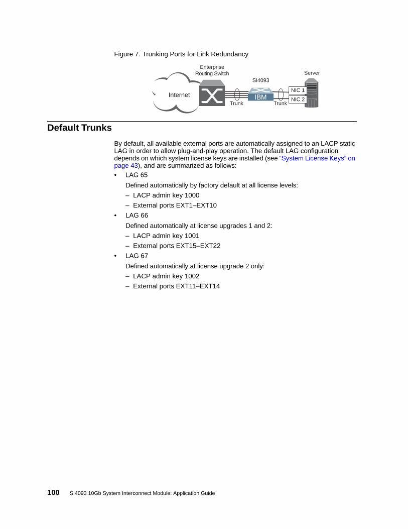
100 SI4093 10Gb System Interconnect Module: Application Guide
Figure 7. Trunking Ports for Link Redundancy
Default Trunks
By default, all available external ports are automatically assigned to an LACP static LAG in order to allow plug-and-play operation. The default LAG configuration depends on which system license keys are installed (see “System License Keys” on page 43), and are summarized as follows:
• LAG 65
Defined automatically by factory default at all license levels:
– LACP admin key 1000
– External ports EXT1–EXT10
• LAG 66
Defined automatically at license upgrades 1 and 2:
– LACP admin key 1001
– External ports EXT15–EXT22
• LAG 67
Defined automatically at license upgrade 2 only:
– LACP admin key 1002
– External ports EXT11–EXT14
TrunkTrunk
ServerSI4093
NIC 1
NIC 2Internet
EnterpriseRouting Switch

© Copyright IBM Corp. 2014 Chapter 11: Trunking 101
Static Trunks
Before Configuring Static Trunks
When you create and enable a static trunk, the trunk members (ports) take on certain settings necessary for correct operation of the trunking feature.
Before you configure your trunk, you must consider these settings, along with specific configuration rules, as follows:
• Read the configuration rules provided in the section, “Static Trunk Group Configuration Rules” on page 101.”
• Determine which SI4093 ports are to become trunk members (the specific ports making up the trunk).
• Ensure that the chosen ports are set to enabled.
• Ensure all member ports in a trunk have the same VLAN configuration.
• Consider how existing VLANs will be affected by the addition of a trunk.
Static Trunk Group Configuration Rules
The trunking feature operates according to specific configuration rules. When creating trunks, consider the following rules that determine how a trunk group reacts in any network topology:
• All trunks must originate from one network entity and lead to one destination entity. For example, you cannot combine links from two different servers into one trunk group.
• Any physical SI4093 port can belong to only one trunk group.
• Depending on port availability, the SI4093 supports up to 16 ports in each trunk group.
• Internal ports (INTx) and external ports (EXTx) cannot become members of the same trunk group.
• Trunking from third-party devices must comply with Cisco® EtherChannel® technology.
• All trunk member ports must be assigned to the same VLAN configuration before the trunk can be enabled.
• If you change the VLAN settings of any trunk member, you cannot apply the change until you change the VLAN settings of all trunk members.
• When an active port is configured in a trunk, the port becomes a trunk member when you enable the trunk.
• All ports in static trunks must have the same link configuration (speed, duplex, flow control).
• When defining trunks, if any of the desired ports is already a member of an existing SPAR, you must first remove those ports from their old SPAR. Likewise, if a desired port is part of an existing trunk or LACP LAG, you must also remove the desired ports from their old trunk or LAG.

102 SI4093 10Gb System Interconnect Module: Application Guide
Configuring a Static Port Trunk
In the example below, three ports are trunked between the SI4093 and an application switch.
Figure 8. Port Trunk Group Configuration Example
Prior to configuring each device in the above example, you must connect to the appropriate device as the administrator.
1. Connect the ports that will be members in the trunk group.
2. Configure the trunk using these steps on the SI4093:
a. Define a trunk group..
b. Verify the configuration
Examine the resulting information. If any settings are incorrect, make appropriate changes.
3. Repeat the process on the application switch.
Trunk group 1 (on the SI4093) is now connected to trunk group 3 on the application switch.
Note: In this example, a SI4093 and an IBM application switch are used. If a third-party device supporting link aggregation is used (such as Cisco routers and switches with EtherChannel technology or Sun's Quad Fast Ethernet Adapter), trunk groups on the third-party device should be configured manually. Connection problems could arise when using automatic trunk group negotiation on the third-party device.
Application Switch
IBM Flex Chassis
SI4093
Application Switch, Trunk 3: Ports 2, 12, and 22
SI4093, Trunk 1: Ports EXT1, EXT2, and EXT3
AggregatePort Trunk
EX
T1
EX
T2
EX
T3
SIM(config)# portchannel 1 port ext1,ext2,ext3SIM(config)# portchannel 1 enable
SIM(config)# show portchannel information
RS G8011(config)# portchannel 3 port 2,12,22RS G8011(config)# portchannel 3 enable

© Copyright IBM Corp. 2014 Chapter 11: Trunking 103
4. Examine the trunking information on each device.
Information about each port in each configured trunk group is displayed. Make sure that trunk groups consist of the expected ports and that each port is in the expected state.
SIM(config)# show portchannel informationPortChannel 1: EnabledProtocol - StaticPort State: EXT1: forwarding EXT2: forwarding EXT3: forwarding

104 SI4093 10Gb System Interconnect Module: Application Guide
Configurable Trunk Hash Algorithm
Traffic in a trunk group is statistically distributed among member ports using a hash process where various address and attribute bits from each transmitted frame are recombined to specify the particular trunk port the frame will use. The SI4093 uses the RTAG7 model for trunk hashing.
The SI4093 can be configured to use a variety of hashing options. To achieve the most even traffic distribution, select options that exhibit a wide range of values for your particular network. Avoid hashing on information that is not usually present in the expected traffic, or which does not vary.
The SI4093 supports the following hashing options:
• Layer 2 source MAC address
• Layer 2 destination MAC address
• Layer 2 source and destination MAC address
• Layer 3 IPv4/IPv6 source IP address
• Layer 3 IPv4/IPv6 destination IP address (the default)
• Layer 3 source and destination IPv4/IPv6 address (the default)
• Layer 2 hash configuration
• Layer 4 port hash
• Ingress port hash
SIM(config)# portchannel thash l2thash l2-source-mac-address
SIM(config)# portchannel thash l2thash l2-destination-mac-address
SIM(config)# portchannel thash l2thash l2-source-destination-mac
SIM(config)# portchannel thash l3thash l3-source-ip-address
SIM(config)# portchannel thash l3thash l3-destination-ip-address
SIM(config)# portchannel thash l3thash l3-source-destination-ip
SIM(config)# portchannel thash l3thash l3-use-l2-hash
SIM(config)# portchannel thash l4port
SIM(config)# portchannel thash ingress

© Copyright IBM Corp. 2014 Chapter 11: Trunking 105
Link Aggregation Control Protocol
LACP Overview
Link Aggregation Control Protocol (LACP) is an IEEE 802.3ad standard for grouping several physical ports into one logical port (known as a dynamic trunk group or Link Aggregation Group) with any device that supports the standard. Please refer to IEEE 802.3ad-2002 for a full description of the standard.
IEEE 802.3ad allows standard Ethernet links to form a single Layer 2 link using the Link Aggregation Control Protocol (LACP). Link aggregation is a method of grouping physical link segments of the same media type and speed in full duplex, and treating them as if they were part of a single, logical link segment. If a link in a LACP trunk group fails, traffic is reassigned dynamically to the remaining link or links of the dynamic trunk group.
In general, LACP must be configured on both the SI4093 as well as on the connecting device. This section describes LACP on the SI4093. For configuring LACP on the connecting device, see the appropriate product documentation.
The SI4093 supports up to 64 LACP trunks, each with up to 16 ports.
Note: LACP implementation in IBM Networking OS does not support the Churn machine, an option used to detect if the port is operable within a bounded time period between the actor and the partner. Only the Marker Responder is implemented, and there is no marker protocol generator.
A port’s Link Aggregation Identifier (LAG ID) determines how the port can be aggregated. The Link Aggregation ID (LAG ID) is constructed mainly from the system ID and the port’s admin key, as follows:
• System ID: an integer value based on the SI4093’s MAC address and the system priority assigned in the CLI.
• Admin key: a port’s admin key is an integer value (1 - 65535) that you can configure in the CLI. Each SI4093 port that participates in the same LACP trunk group must have the same admin key value. The admin key is local significant, which means the partner device does not need to use the same admin key value.
For example, consider two devices, the SI4093 and a Partner switch, as shown in Table 15.
In the configuration shown in Table 15, the SI4093 ports EXT1 and EXT2 are aggregated to form an LACP trunk group with Partner switch ports 1 and 2. Only ports with the same LAG ID are aggregated in the trunk group. The SI4093 port EXT3 is not aggregated in the trunk group because it has a different LAG ID. Other ports configured with the same admin key on the SI4093 but with a different LAG ID (due to Partner switch admin key configuration or due to Partner switch MAC
Table 15. Actor vs. Partner LACP configuration
SI4093 Partner Switch
Port EXT1 (LAG = 65, admin key = 100) Port 1 (admin key = 50)
Port EXT2 (LAG = 65, admin key = 100) Port 2 (admin key = 50)
Port EXT3 (LAG = 66, admin key = 100) Port 3 (admin key = 70)

106 SI4093 10Gb System Interconnect Module: Application Guide
address being different) can be aggregated in another trunk group. For instance, SI4093 port EXT3 can be aggregated in another trunk group with ports that have the same LAG ID as port EXT3.
To prevent SI4093 ports (with the same admin key) from aggregating in another trunk group, you can configure a trunk ID. Ports with the same admin key (although with different LAG IDs) compete to get aggregated into a trunk group. The LAG ID for the trunk group is decided based on the first port that is aggregated in the group. Ports with this LAG ID get aggregated and the other ports are placed in suspended mode. As per the configuration shown in Table 15 on page 105, if port EXT1 gets aggregated first, then the LAG ID of port EXT1 would be the LAG ID of the trunk. Port EXT3 would be placed in suspended mode. When in suspended mode, a port transmits only LACP data units (LACPDUs) and discards all other traffic.
A port may also be placed in suspended mode for the following reasons:
• When LACP is configured on the port but it stops receiving LACPDUs from the partner switch.
• When the port has a different LAG ID because of the partner switch MAC being different. For example: when the SI4093 is connected to two partners.
Trunk ID can be viewed using the following command:
LACP provides for the controlled addition and removal of physical links for the link aggregation.
Each port in the SI4093 can have one of the following LACP modes.
• off (default)
The user can configure this port in to a regular static trunk group.
• activeThe port is capable of forming an LACP trunk. This port sends LACPDU packets to partner system ports.
• passiveThe port is capable of forming an LACP trunk. This port only responds to the LACPDU packets sent from an LACP active port.
Each active LACP port transmits LACP data units (LACPDUs), while each passive LACP port listens for LACPDUs. During LACP negotiation, the admin key is exchanged. The LACP trunk group is enabled as long as the information matches at both ends of the link. If the admin key value changes for a port at either end of the link, that port’s association with the LACP trunk group is lost.
When the system is initialized, all ports by default are in LACP off mode and are assigned unique admin keys. To make a group of ports available for aggregation, you assign them all the same admin key. You must set the port’s LACP mode to active to activate LACP negotiation. You can set other port’s LACP mode to passive, to reduce the amount of LACPDU traffic at the initial trunk-forming stage.
In the information displays, static trunks are listed as trunks 1 though 64. Dynamic trunks are listed as 65 through 128.
SIM # show lacp information

© Copyright IBM Corp. 2014 Chapter 11: Trunking 107
Configuring LACP
Use the following procedure to configure LACP in order for port EXT1 and port EXT2 to participate in link aggregation.
1. Configure port parameters. All ports that participate in the LACP trunk group must have the same settings, including VLAN membership.
2. Define a portchannel by assigning an ID and an LACP admin key:
3. Select the ports and bind the LACP admin key. Only ports with the same admin key can form an LACP trunk group.
Note: If any of the desired ports is a member of an existing SPAR, you must first remove those ports from their old SPAR. Likewise, if a desired port is part of another LAG, you must also remove the desired ports from their old LAG (see “Configuring SPAR Ports” on page 87).
4. Set the LACP mode.
SIM(config)# portchannel 65 lacp key 100 suspend-individual
SIM(config)# interface port ext1-ext2SIM(config-if)# lacp key 100
SIM(config-if)# lacp mode activeSIM(config-if)# exit

108 SI4093 10Gb System Interconnect Module: Application Guide

© Copyright IBM Corp. 2014 109
Chapter 12. Quality of Service
Quality of Service (QoS) features allow you to allocate network resources to mission-critical applications at the expense of applications that are less sensitive to such factors as time delays or network congestion. You can configure your network to prioritize specific types of traffic, ensuring that each type receives the appropriate QoS level.
The following topics are discussed in this section:
• “QoS Overview” on page 109• “Using ACL Filters” on page 111• “Using 802.1p Priorities to Provide QoS” on page 113• “Queuing and Scheduling” on page 114
QoS Overview
QoS helps you allocate guaranteed bandwidth to critical applications, and limit bandwidth for less critical applications. Applications such as video and voice must have a certain amount of bandwidth to work correctly; using QoS, you can provide that bandwidth when necessary. Also, you can put a high priority on applications that are sensitive to timing out or those that cannot tolerate delay, assigning that traffic to a high-priority queue.
By assigning QoS levels to traffic flows on your network, you can ensure that network resources are allocated where they are needed most. QoS features allow you to prioritize network traffic, thereby providing better service for selected applications.
Figure 9 on page 109 shows the basic QoS model used by the SI4093 10Gb System Interconnect Module (SI4093).
Figure 9. QoS Model
The SI4093 uses the Differentiated Services (DiffServ) architecture to provide QoS functions. DiffServ is described in IETF RFC 2474 and RFC 2475.
With DiffServ, you can establish policies for directing traffic. A policy is a traffic-controlling mechanism that monitors the characteristics of the traffic (for example, its source, destination, and protocol) and performs a controlling action on the traffic when certain characteristics are matched.
Ports
ACLFilter
ACLMeter
Drop/Pass/Re-Mark
ClassifyPackets
PerformActions
EgressIngress
COSQueue
MeterTraffic
Queue andSchedule

110 SI4093 10Gb System Interconnect Module: Application Guide
The SI4093 can classify traffic by reading the DiffServ Code Point (DSCP) or IEEE 802.1p priority value, or by using filters to match specific criteria. When network traffic attributes match those specified in a traffic pattern, the policy instructs the SI4093 to perform specified actions on each packet that passes through it. The packets are assigned to different Class of Service (COS) queues and scheduled for transmission.
The basic SI4093 QoS model works as follows:
• Classify traffic:
– Read DSCP
– Read 802.1p Priority
– Match ACL filter parameters
• Meter traffic:
– Define bandwidth and burst parameters
– Select actions to perform on in-profile and out-of-profile traffic
• Perform actions:
– Drop packets
– Pass packets
– Mark DSCP or 802.1p Priority
– Set COS queue (with or without re-marking)
• Queue and schedule traffic:
– Place packets in one of the available COS queues
– Schedule transmission based on the COS queue weight

© Copyright IBM Corp. 2014 Chapter 12: Quality of Service 111
Using ACL Filters
Access Control Lists (ACLs) are filters that allow you to classify and segment traffic, so you can provide different levels of service to different traffic types. Each filter defines conditions that packets must match for inclusion in a particular service class, and also the actions that are performed for matching traffic.
The SI4093 allows you to classify packets based on various parameters. For example:
• Ethernet—source MAC, destination MAC, VLAN number/mask, Ethernet type, priority
• IPv4—source IP address/mask, destination address/mask, type of service, IP protocol number
• IPv6—source IP address/prefix, destination address/prefix, next header, flow label, traffic class
• TCP/UPD—source port, destination port, TCP flag• Packet format—Ethernet format, tagging format, IPv4, IPv6• Egress port
For ACL details, see “Access Control Lists” on page 75.
Summary of ACL Actions
Actions determine how the traffic is treated. The SI4093 QoS actions include the following:
• Pass or Drop the packet• Re-mark the packet with a new DiffServ Code Point (DSCP)• Re-mark the 802.1p field• Set the COS queue
ACL Metering and Re-Marking
You can define a profile for the aggregate traffic flowing through the SI4093 by configuring a QoS meter (if desired) and assigning ACL Groups to ports. When you add ACL Groups to a port, make sure they are ordered correctly in terms of precedence.
Actions taken by an ACL are called In-Profile actions. You can configure additional In-Profile and Out-of-Profile actions on a port. Data traffic can be metered, and re-marked to ensure that the traffic flow provides certain levels of service in terms of bandwidth for different types of network traffic.

112 SI4093 10Gb System Interconnect Module: Application Guide
Metering
QoS metering provides different levels of service to data streams through user-configurable parameters. A meter is used to measure the traffic stream against a traffic profile which you create. Thus, creating meters yields In-Profile and Out-of-Profile traffic for each ACL, as follows:
• In-Profile–If there is no meter configured or if the packet conforms to the meter, the packet is classified as In-Profile.
• Out-of-Profile–If a meter is configured and the packet does not conform to the meter (exceeds the committed rate or maximum burst rate of the meter), the packet is classified as Out-of-Profile.
Note: Metering is not supported for IPv6 ACLs. All traffic matching an IPv6 ACL is considered in-profile for re-marking purposes.
Using meters, you set a Committed Rate in Kbps (1000 bits per second in each Kbps). All traffic within this Committed Rate is In-Profile. Additionally, you can set a Maximum Burst Size that specifies an allowed data burst larger than the Committed Rate for a brief period. These parameters define the In-Profile traffic.
Meters keep the sorted packets within certain parameters. You can configure a meter on an ACL, and perform actions on metered traffic, such as packet re-marking.
Re-Marking
Re-marking allows for the treatment of packets to be reset based on new network specifications or desired levels of service. You can configure the ACL to re-mark a packet as follows:
• Change the DSCP value of a packet, used to specify the service level traffic should receive.
• Change the 802.1p priority of a packet.

© Copyright IBM Corp. 2014 Chapter 12: Quality of Service 113
Using 802.1p Priorities to Provide QoS
802.1p Overview
IBM Networking OS provides Quality of Service functions based on the priority bits in a packet’s VLAN header. (The priority bits are defined by the 802.1p standard within the IEEE 802.1q VLAN header.) The 802.1p bits, if present in the packet, specify the priority that should be given to packets during forwarding. Packets with a numerically higher (non-zero) priority are given forwarding preference over packets with lower priority bit value.
The IEEE 802.1p standard uses eight levels of priority (0-7). Priority 7 is assigned to highest priority network traffic, such RIP routing table updates, priorities 5-6 are assigned to delay-sensitive applications such as voice and video, and lower priorities are assigned to standard applications. A value of 0 (zero) indicates a “best effort” traffic prioritization, and this is the default when traffic priority has not been configured on your network. The SI4093 can filter packets based on the 802.1p values, and it can assign or overwrite the 802.1p value in the packet.
Figure 10. Layer 2 802.1q/802.1p VLAN Tagged Packet
Ingress packets receive a priority value, as follows:
• Tagged packets—SI4093 reads the 802.1p priority in the VLAN tag.
• Untagged packets—SI4093 tags the packet and assigns an 802.1p priority, based on the port’s default priority.
Egress packets are placed in a COS queue based on the priority value, and scheduled for transmission based on the scheduling weight of the COS queue.
To configure a port’s default 802.1p priority value, use the following commands.
7 6 5 4 3 2 1 0
Priority
7 6 5 4 3 2 1 0
VLAN Identifier (VID)
SFD DMAC SMAC Tag E Type Data FCSPreamble
SIM(config)# interface port ext1SIM(config-if)# dot1p <802.1p value (0-7)>SIM(config-if)# exit

114 SI4093 10Gb System Interconnect Module: Application Guide
Queuing and Scheduling
The SI4093 can be configured to have either 2 or 8 output Class of Service (COS) queues per port, into which each packet is placed. Each packet’s 802.1p priority determines its COS queue, except when an ACL action sets the COS queue of the packet.
You can configure the following attributes for COS queues:
• Map 802.1p priority value to a COS queue
• Define the scheduling weight of each COS queue
You can map 802.1p priority value to a COS queue, as follows:
To set the COS queue scheduling weight, use the following command.
The scheduling weight can be set from 0 to 15. Weight values from 1 to 15 set the queue to use weighted round-robin (WRR) scheduling, which distributes larger numbers of packets to queues with the highest weight values. For distribution purposes, each packet is counted the same, regardless of the packet’s size.
A scheduling weight of 0 (zero) indicates strict priority. Traffic in strict priority queue has precedence over other all queues. If more than one queue is assigned a weight of 0, the strict queue with highest queue number will be served first. Once all traffic in strict queues is delivered, any remaining bandwidth will be allocated to the WRR queues, divided according to their weight values.
Note: Use caution when assigning strict scheduling to queues. Heavy traffic in queues assigned with a weight of 0 can starve lower priority queues.
For a scheduling method that uses a weighted deficit round-robin (WDRR) algorithm, distributing packets with an awareness of packet size, see “Enhanced Transmission Selection” on page 140.
SIM(config)# qos transmit-queue mapping <802.1p priority value (0-7)> <COS queue (0-7)>
SIM(config)# qos transmit-queue weight-cos <COSq number> <COSq weight (0-15)>

© Copyright IBM Corp. 2014 115
Chapter 13. Basic IP Addresses
This chapter provides configuration background and examples for using the SI4093 10Gb System Interconnect Module (SI4093) to perform BOOTP and DHCP functions.
Dynamic Host Configuration Protocol (DHCP) provides a framework for automatically assigning IP addresses and configuration information to other IP hosts or clients in a large TCP/IP network. Without DHCP, the IP address must be entered manually for each network device. DHCP allows a network administrator to distribute IP addresses from a central point and automatically send a new IP address when a device is connected to a different place in the network.
DHCP is an extension of another network IP management protocol, Bootstrap Protocol (BOOTP), with an additional capability of being able to dynamically allocate reusable network addresses and configuration parameters for client operation.
Built on the client/server model, DHCP allows hosts or clients on an IP network to obtain their configurations from a DHCP server, thereby reducing network administration. The most significant configuration the client receives from the server is its required IP address; (other optional parameters include the “generic” file name to be booted, the address of the default gateway, and so forth).
To enable the DHCP client on the SI4093, use the following command:
SIM(config)# system dhcp

116 SI4093 10Gb System Interconnect Module: Application Guide

© Copyright IBM Corp. 2014 117
Chapter 14. Internet Protocol Version 6
Internet Protocol version 6 (IPv6) is a network layer protocol intended to expand the network address space. IPv6 is a robust and expandable protocol that meets the need for increased physical address space. The switch supports the following RFCs for IPv6-related features:
This chapter describes the basic configuration of IPv6 addresses and how to manage the switch via IPv6 host management.
IPv6 Limitations
The following IPv6 feature restrictions apply to this release.
• Dynamic Host Control Protocol for IPv6 (DHCPv6) is supported only on the management interface (MGT-port).
• Routing Information Protocol for IPv6 (RIPng) is not supported.
Most other IBM Networking OS 7.8 features permit IP addresses to be configured using either IPv4 or IPv6 address formats. However, the following switch features support IPv4 only:
• Default switch management IP address• Bootstrap Protocol (BOOTP)• DHCP for internal management interfaces 127 and 128• RADIUS, TACACS+ and LDAP• QoS metering and re-marking ACLs for out-profile traffic• VMware Virtual Center (vCenter) for VMready• sFLOW
• RFC 1981• RFC 2451• RFC 2460• RFC 2461• RFC 2462• RFC 2474• RFC 2526
• RFC 2711• RFC 3289• RFC 3306• RFC 3307• RFC 3411• RFC 3412• RFC 3413
• RFC 3414• RFC 3484• RFC 3602• RFC 3879• RFC 4007• RFC 4213• RFC 4291
• RFC 4293• RFC 4293• RFC 4443• RFC 4861• RFC 4862• RFC 5095

118 SI4093 10Gb System Interconnect Module: Application Guide
IPv6 Address Format
The IPv6 address is 128 bits (16 bytes) long and is represented as a sequence of eight 16-bit hex values, separated by colons.
Each IPv6 address has two parts:
• Subnet prefix representing the network to which the interface is connected
• Local identifier, either derived from the MAC address or user-configured
The preferred hexadecimal format is as follows:
xxxx:xxxx:xxxx:xxxx:xxxx:xxxx:xxxx:xxxx
Example IPv6 address:
FEDC:BA98:7654:BA98:FEDC:1234:ABCD:5412
Some addresses can contain long sequences of zeros. A single contiguous sequence of zeros can be compressed to :: (two colons). For example, consider the following IPv6 address:
FE80:0:0:0:2AA:FF:FA:4CA2
The address can be compressed as follows:
FE80::2AA:FF:FA:4CA2
Unlike IPv4, a subnet mask is not used for IPv6 addresses. IPv6 uses the subnet prefix as the network identifier. The prefix is the part of the address that indicates the bits that have fixed values or are the bits of the subnet prefix. An IPv6 prefix is written in address/prefix-length notation. For example, in the following address, 64 is the network prefix:
21DA:D300:0000:2F3C::/64
IPv6 addresses can be either user-configured or automatically configured. Automatically configured addresses always have a 64-bit subnet prefix and a 64-bit interface identifier. In most implementations, the interface identifier is derived from the switch's MAC address, using a method called EUI-64.
Most IBM Networking OS 7.8 features permit IP addresses to be configured using either IPv4 or IPv6 address formats. Throughout this manual, IP address is used in places where either an IPv4 or IPv6 address is allowed. In places where only one type of address is allowed, the type (IPv4 or IPv6 is specified).

© Copyright IBM Corp. 2014 Chapter 14: Internet Protocol Version 6 119
IPv6 Address Types
IPv6 supports three types of addresses: unicast (one-to-one), multicast (one-to-many), and anycast (one-to-nearest). Multicast addresses replace the use of broadcast addresses.
Unicast Address
Unicast is a communication between a single host and a single receiver. Packets sent to a unicast address are delivered to the interface identified by that address. IPv6 defines the following types of unicast address:
• Global Unicast address: An address that can be reached and identified globally. Global Unicast addresses use the high-order bit range up to FF00, therefore all non-multicast and non-link-local addresses are considered to be global unicast. A manually configured IPv6 address must be fully specified. Autoconfigured IPv6 addresses are comprised of a prefix combined with the 64-bit EUI. RFC 4291 defines the IPv6 addressing architecture.
The interface ID must be unique within the same subnet.
• Link-local unicast address: An address used to communicate with a neighbor on the same link. Link-local addresses use the format FE80::EUI
Link-local addresses are designed to be used for addressing on a single link for purposes such as automatic address configuration, neighbor discovery, or when no routers are present.
Routers must not forward any packets with link-local source or destination addresses to other links.
Multicast
Multicast is communication between a single host and multiple receivers. Packets are sent to all interfaces identified by that address. An interface may belong to any number of multicast groups.
A multicast address (FF00 - FFFF) is an identifier for a group interface. The multicast address most often encountered is a solicited-node multicast address using prefix FF02::1:FF00:0000/104 with the low-order 24 bits of the unicast or anycast address.
The following well-known multicast addresses are pre-defined. The group IDs defined in this section are defined for explicit scope values, as follows:
FF00:::::::0 through FF0F:::::::0
Anycast
Packets sent to an anycast address or list of addresses are delivered to the nearest interface identified by that address. Anycast is a communication between a single sender and a list of addresses.
Anycast addresses are allocated from the unicast address space, using any of the defined unicast address formats. Thus, anycast addresses are syntactically indistinguishable from unicast addresses. When a unicast address is assigned to more than one interface, thus turning it into an anycast address, the nodes to which the address is assigned must be explicitly configured to know that it is an anycast address.

120 SI4093 10Gb System Interconnect Module: Application Guide
IPv6 Address Autoconfiguration
IPv6 supports the following types of address autoconfiguration:
• Stateful address configuration
Address configuration is based on the use of a stateful address configuration protocol, such as DHCPv6, to obtain addresses and other configuration options.
• Stateless address configuration
Address configuration is based on the receipt of Router Advertisement messages that contain one or more Prefix Information options.
IBM Networking OS 7.8 supports stateless address configuration.
Stateless address configuration allows hosts on a link to configure themselves with link-local addresses and with addresses derived from prefixes advertised by local routers. Even if no router is present, hosts on the same link can configure themselves with link-local addresses and communicate without manual configuration.
IPv6 Management Interfaces
Management interfaces 125 and 126 support multiple IPv6 addresses. You can manually configure up to two IPv6 addresses for each management interface, or you can allow the switch to use stateless autoconfiguration. By default, the switch automatically configures the IPv6 address of its management interfaces.
You can manually configure two IPv6 addresses for each interface, as follows:
• Initial IPv6 address is a global unicast or anycast address:
interface ip <x>address <IPv6 address>
Note that you cannot configure both addresses as anycast. If you configure an anycast address on the interface you must also configure a global unicast address on that interface.
• Second IPv6 address can be a unicast or anycast address:
interface ip <x>secaddr6 <IPv6 address>
You cannot configure an IPv4 address on an IPv6 management interface. Each interface can be configured with only one address type: either IPv4 or IPv6, but not both. When changing between IPv4 and IPv6 address formats, the prior address settings for the interface are discarded.
Each IPv6 interface can belong to only one VLAN. Each VLAN can support only one IPv6 interface. Each VLAN can support multiple IPv4 interfaces.
Interface 125/126 is reserved for IPv6 host support. This interface is included in management VLAN 4095. Use IPv6 gateway mode to configure the IPv6 gateways (ip gateway6 {<gateway number>} address <IPv6 address>).
IPv6 gateway 3 and 4 are the default IPv6 management gateways.

© Copyright IBM Corp. 2014 Chapter 14: Internet Protocol Version 6 121
Neighbor Discovery
The switch uses Neighbor Discovery protocol (ND) to gather information about other router and host nodes, including the IPv6 addresses. Host nodes use ND to configure their interfaces and perform health detection. ND allows each node to determine the link-layer addresses of neighboring nodes, and to keep track of each neighbor’s information. A neighboring node is a host or a router that is linked directly to the switch. The switch supports Neighbor Discovery as described in RFC 4861.
Neighbor Discover messages allow network nodes to exchange information, as follows:
• Neighbor Solicitations allow a node to discover information about other nodes.
• Neighbor Advertisements are sent in response to Neighbor Solicitations. The Neighbor Advertisement contains information required by nodes to determine the link-layer address of the sender, and the sender’s role on the network.
• IPv6 hosts use Router Solicitations to discover IPv6 routers. When a router receives a Router Solicitation, it responds immediately to the host.
• Routers uses Router Advertisements to announce its presence on the network, and to provide its address prefix to neighbor devices. IPv6 hosts listen for Router Advertisements, and uses the information to build a list of default routers. Each host uses this information to perform autoconfiguration of IPv6 addresses.
• Redirect messages are sent by IPv6 routers to inform hosts of a better first-hop address for a specific destination. Redirect messages are only sent by routers for unicast traffic, are only unicast to originating hosts, and are only processed by hosts.
ND configuration for various advertisements, flags, and interval settings is performed on a per-interface basis using the following commands:
Other ND configuration options are available using the following commands:
SIM(config)# interface ip <interface number>SIM(config-ip-if)# ipv6 nd <command>
SIM(config)# ip neighbors <commands> (Manage static neighbor cache entries)SIM(config)# ipv6 nd ndprefix <prefix> (Define prefix profiles for router advertisements sent from
an interface)

122 SI4093 10Gb System Interconnect Module: Application Guide
Supported Applications
The following applications have been enhanced to provide IPv6 support.
• Ping
The ping command supports IPv6 addresses. Use the following format to ping an IPv6 address:
ping <host name>|<IPv6 address> [-n <tries (0-4294967295)>] [-w <msec delay (0-4294967295)>] [-l <length (0/32-65500/2080)>] [-s <IP source>] [-v <TOS (0-255)>] [-f] [-t]
To ping a link-local address (begins with FE80), provide an interface index, as follows:
ping <IPv6 address>%<Interface index> [-n <tries (0-4294967295)>] [-w <msec delay (0-4294967295)>] [-l <length (0/32-65500/2080)>] [-s <IP source>] [-v <TOS (0-255)>] [-f] [-t]
• Traceroute
The traceroute command supports IPv6 addresses (but not link-local addresses). Use the following format to perform a traceroute to an IPv6 address:
traceroute <host name>| <IPv6 address> [<max-hops (1-32)> [<msec delay (1-4294967295)>]]
• Telnet
The telnet command supports IPv6 addresses, but not link-local addresses. Use the following format to Telnet to an IPv6 address:
telnet <host name>| <IPv6 address> [<port>]
• SSH
Secure Shell (SSH) connections over IPv6 are supported, but not link-local addresses. The following syntax is required from the client:
ssh -u <IPv6 address>
Example:
ssh -u 2001:2:3:4:0:0:0:142
• TFTP
The TFTP commands support both IPv4 and IPv6 addresses. Link-local addresses are not supported.
• FTP
The FTP commands support both IPv4 and IPv6 addresses. Link-local addresses are not supported.

© Copyright IBM Corp. 2014 Chapter 14: Internet Protocol Version 6 123
• DNS client
DNS commands support both IPv4 and IPv6 addresses. Link-local addresses are not supported. Use the following command to specify the type of DNS query to be sent first:
If you set the request version to v4, the DNS application sends an A query first, to resolve the hostname with an IPv4 address. If no A record is found for that hostname (no IPv4 address for that hostname) an AAAA query is sent to resolve the hostname with a IPv6 address.
If you set the request version to v6, the DNS application sends an AAAA query first, to resolve the hostname with an IPv6 address. If no AAAA record is found for that hostname (no IPv6 address for that hostname) an A query is sent to resolve the hostname with an IPv4 address.
Configuration Guidelines
When you configure an interface for IPv6, consider the following guidelines:
• Support for subnet router anycast addresses is not available.
• Interfaces 125 and 126 are reserved for IPv6 management.
• A single interface can accept either IPv4 or IPv6 addresses, but not both IPv4 and IPv6 addresses.
• A single interface can accept multiple IPv6 addresses.
• A single interface can accept only one IPv4 address.
• If you change the IPv6 address of a configured interface to an IPv4 address, all IPv6 settings are deleted.
• Health checks are not supported for IPv6 gateways.
• IPv6 interfaces support Path MTU Discovery. The CPU’s MTU is fixed at 1500 bytes.
• Support for jumbo frames (1,500 to 9,216 byte MTUs) is limited. Any jumbo frames intended for the CPU must be fragmented by the remote node. The switch can re-assemble fragmented packets up to 9k. It can also fragment and transmit jumbo packets received from higher layers.
SIM(config)# ip dns ipv6 request-version {ipv4|ipv6}

124 SI4093 10Gb System Interconnect Module: Application Guide
IPv6 Configuration Examples
This section provides steps to configure IPv6 on the switch.
IPv6 Example 1
The following example uses IPv6 host mode to autoconfigure an IPv6 address for the management interface.
1. Enable IPv6 host mode on an interface.
2. Configure (select and enable) the IPv6 default gateway.
3. Verify the interface address.
IPv6 Example 2
Use the following example to manually configure IPv6 on an interface.
1. Assign an IPv6 address and prefix length to the interface.
The secondary IPv6 address is compressed, and the prefix length is 32.
2. Configure the IPv6 default gateway.
3. Configure Router advertisements for the interface (optional)
4. Verify the configuration.
SIM(config)# interface ip 125 (Select IP interface 125)SIM(config-ip-if)# ip6host (Enable IPv6 host modeSIM(config-ip-if)# enable (Enable the IP interface)
SIM(config)# ip gateway6 3 address 2001:BA98:7654:BA98:FEDC:1234:ABCD:5412 enable
SIM(config)# show interface ip 125 (Display interface information)
SIM(config)# interface ip 125SIM(config-ip-if)# ipv6 address 2001:BA98:7654:BA98:FEDC:1234:ABCD:5214 32 enaSIM(config-ip-if)# ipv6 prefixlen 64SIM(config-ip-if)# ipv6 secaddr6 address 2003::1 32
SIM(config)# ip gateway6 3 address 2001:BA98:7654:BA98:FEDC:1234:ABCD:5412 ena(Enable default gateway)
SIM(config-ip-if)# ipv6 nd advmtu (Enable Router Advertisements)
SIM# show ipv6 interface (View current IP settings)
SIM# show ipv6 gateway6 3 (View current IP gateway 3 settings)

© Copyright IBM Corp. 2014 125
Chapter 15. Fibre Channel over Ethernet
FCOE Overview
Fibre Channel over Ethernet (FCoE) is an effort to converge two of the different physical networks in today’s data centers. It allows Fibre Channel traffic (such as that commonly used in Storage Area Networks, or SANs) to be transported without loss over 10Gb Ethernet links (typically used for high-speed Local Area Networks, or LANs). This provides an evolutionary approach toward network consolidation, allowing Fibre Channel equipment and tools to be retained, while leveraging cheap, ubiquitous Ethernet networks for growth.
With server virtualization, servers capable of hosting both Fibre Channel and Ethernet applications will provide advantages in server efficiency, particularly as FCoE-enabled network adapters provide consolidated SAN and LAN traffic capabilities.
The IBM Flex System Fabric SI4093 System Interconnect Module with IBM Networking OS 7.8 software is compliant with the INCITS T11.3, FC-BB-5 FCoE specification.
Note: On the SI4093, CEE features for transparent (non-FIP snooping) FCoE are turned on by default. If you are not using FCoE, it is recommended that you turn off CEE. See “Turning CEE On or Off” on page 128.
The FCoE Topology
In an end-to-end Fibre Channel network, switches and end devices generally establish trusted, point-to-point links. Fibre Channel switches validate end devices, enforce zoning configurations and device addressing, and prevent certain types of errors and attacks on the network.
In a converged multi-hop FCoE network where Fibre Channel devices are bridged to Ethernet devices, the direct point-to-point assurances normally provided by the Fibre Channel fabric may be lost in the transition between the different network types. However, the SI4093 provides a solution for this problem.
Figure 11. A Mixed Fibre Channel and FCoE Network
In Figure 11 on page 125, the Fibre Channel network is connected to the FCoE network through an Fibre Channel Forwarder (FCF) bridge. The FCF acts as a Fibre Channel gateway to and from the multi-hop FCoE network.
SI4093
Servers IBM Chassis
EXT5
EXT4INTA1
INTA20-24
LANBusiness-Critical LAN
802.1p Priority & Usage
3 FCoE Applications802.1p Priority & Usage
FCoE
CNA
CNA LAN
FibreChannelFCF

126 SI4093 10Gb System Interconnect Module: Application Guide
For the FCoE portion of the network, the FCF is connected to the FCoE-enabled SI4093, which is internally connected to a blade server (running Fibre Channel applications) through an FCoE-enabled Converged Network Adapter (CNA) known in Fibre Channel as an Ethernet Node (ENode).
Note: The figure also shows a non-FCoE LAN server connected to the SI4093 using a CNA. This allows the LAN server to take advantage of some CEE features that are useful even outside of an FCoE environment.
FCoE Security
On the SI4093, FCoE security behaves differently depending on whether a transparent SPAR or a VLAN-aware SPAR is used.
FIP-Aware FCoE
The SI4093 can block undesired or unvalidated traffic on FCoE links that exists outside the regular Fibre Channel topology, Ethernet ports used in FCoE on VLAN-aware SPARs are configured with Access Control Lists (ACLs) that are narrowly tailored to permit expected FCoE traffic to and from confirmed FCFs and ENodes, and deny all other FCoE or FCoE Initialization Protocol (FIP) traffic. This ensures that all FCoE traffic to and from the ENode passes through the FCF.
Because manual ACL configuration is an administratively complex task, the SI4093 can automatically and dynamically configure the ACLs required for use with FCoE on VLAN-aware SPARs. Using FIP snooping (see “FCoE Initialization Protocol Snooping” on page 131), the SI4093 examines the FIP frames normally exchanged between the FCF and ENodes to determine information about connected FCoE devices. This information is used to automatically determine the appropriate ACLs required to block certain types of undesired or unvalidated FCoE traffic.
Automatic FCoE-related ACLs are independent from ACLs used for typical Ethernet purposes.
FIP snooping is globally turned off by default. When the feature is turned on, FIP snooping is can be enabled or disabled on port by port basis. By default, FIP snooping is enabled on all ports.
Transparent FCoE
When FIP snooping is disabled, FCoE security must be fully enforced by the attached servers and upstream devices. For ports where FIP snooping is disabled, the SI4093 does not validate FCoE traffic or automatically install FCoE-related ACLs.
Transparent FCoE is available in transparent SPARs and VLAN-aware SPARs.

© Copyright IBM Corp. 2014 Chapter 15: Fibre Channel over Ethernet 127
FCoE Requirements
The following are required for implementing FCoE using the SI4093 with Networking OS 7.8 software:
• The SI4093 must be connected to the Fibre Channel network through an FCF such as an IBM RackSwitch G8264CS or a Cisco Nexus 5000 Series Switch.
• For each SI4093 internal port participating in FCoE, the connected blade server must use the supported FCoE CNA.Emulex Virtual Fabric Adapter 2-port 10Gb LOM and Emulex Virtual Fabric Adapter (Fabric Mezz) for IBM Flex System, which includes vNIC support (with some additional topology rules), is currently supported.
• For each SI4093 internal port participating in FCoE, the connected blade server must include the appropriate FCoE licenses installed, as obtained using the IBM website Features on Demand (FoD) service. Contact your sales representative for more information on obtaining server feature licenses.
• CEE must be turned on (see “Turning CEE On or Off” on page 128). When CEE is on, the DCBX, PFC, and ETS features are enabled and configured with default FCoE settings. These features may be reconfigured, but must remain enabled in order for FCoE to function.
• FIP snooping is not supported in transparent SPARs. If using a transparent SPARfor FCoE, FIP snooping is ignored, and FCoE security must be enforced by the attached servers and upstream devices.
• If FIP snooping is desired on a SPAR, the SPAR must be configured for VLAN-aware mode and FIP snooping must be must be turned on for the SPAR (see “FCoE Initialization Protocol Snooping” on page 131). When FIP snooping is turned on, the feature is enabled on all ports in the SPAR by default. The administrator can disable FIP snooping on individual ports that do not require FCoE, but FIP snooping must remain enabled on all FCoE ports in order to sup-port secured FCoE sessions in VLAN-aware SPARs.
Port TrunkingIBM Networking OS 7.8 supports port trunking for FCoE connections. The Link Aggregation (LAG) can be used for separate FCoE traffic, or for Ethernet and FCoE traffic. Ports directly connected to servers cannot be combined in a LAG group.
Uplink ports, connected to the FCF, can be grouped as static or dynamic trunks.
Internal ports cannot be grouped as trunks.
Normal trunk operations such as creating/enabling the trunk, and adding/removing member ports can be performed. When a port is added to a trunk group, FCFs previously detected on the port will be deleted. The deleted FCF may be relearned later. However, this may cause flickering in the network traffic.
Priority-based Flow Control (PFC), and Data Center Bridging (DCBX) are configured on a per-port basis. Each port in a trunk must have the same PFC, and DCBX configuration. When a port ceases to be the trunk group member, its configuration does not change.

128 SI4093 10Gb System Interconnect Module: Application Guide
Converged Enhanced Ethernet
Converged Enhanced Ethernet (CEE) refers to a set of IEEE standards designed to allow different physical networks with different data handling requirements to be converged together, simplifying management, increasing efficiency and utilization, and leveraging legacy investments without sacrificing evolutionary growth.
CEE standards were developed primarily to enable Fibre Channel traffic to be carried over Ethernet networks. This required enhancing the existing Ethernet standards to make them lossless on a per-priority traffic basis, and to provide a mechanism to carry converged (LAN/SAN/IPC) traffic on a single physical link. Although CEE standards were designed with FCoE in mind, they are not limited to FCoE installations. CEE features can be utilized in traditional LAN (non-FCoE) networks to provide lossless guarantees on a per-priority basis, and to provide efficient bandwidth allocation based on application needs.
Turning CEE On or OffNote: By default on the SI4093, CEE is turned on. If you are not using FCoE, it is
recommended that you turn off CEE.
To turn CEE on or off, use the following command:
For an example, see “FIP Snooping Configuration” on page 135.
CAUTION:Turning CEE on and applying the configuration will automatically change some 802.1p QoS and 802.3x standard flow control settings on the SI4093. Read the following material carefully to determine whether you will need to take action to reconfigure expected settings.
It is recommended that you backup your configuration prior to turning CEE on. Viewing the file will allow you to manually re-create the equivalent configuration once CEE is turned on, and will also allow you to recover your prior configuration if you need to turn CEE off.
Effects on Link Layer Discovery Protocol
When CEE is turned on, Link Layer Discovery Protocol (LLDP) is automatically turned on and enabled for receiving and transmitting DCBX information. LLDP cannot be turned off while CEE is turned on.
SIM(config)# [no] cee enable

© Copyright IBM Corp. 2014 Chapter 15: Fibre Channel over Ethernet 129
Effects on 802.1p Quality of Service
When CEE is off, the SI4093 allows 802.1p priority values to be used for Quality of Service (QoS) configuration (see the Application Guide). 802.1p QoS default settings are shown in Table 16 on page 129, but can be changed by the administrator.
While CEE is turned on (the default), 802.1p QoS is replaced by ETS (see “Enhanced Transmission Selection” on page 140). As a result, while CEE is turned on, the 802.1p QoS configuration commands are no longer available on the SI4093 (the commands are restored when CEE is turned off).
In addition, while CEE is turned on, any prior 802.1p QoS settings are replaced with new defaults designed for use with ETS priority groups (PGIDs) as shown in Table 16:
When CEE is on, the default ETS configuration also allocates a portion of link bandwidth to each PGID as shown in Table 17:
If the prior, non-CEE configuration used 802.1p priority values for different purposes, or does not expect bandwidth allocation as shown in Table 17 on page 129, when CEE is turned on, the administrator should reconfigure ETS settings as appropriate.
Table 16. CEE Effects on 802.1p Defaults
802.1p QoS ConfigurationWith CEE Off
ETS ConfigurationWith CEE On
Priority COSq Weight Priority COSq PGID
0 0 1 0 0 0
1 1 2 1 0 0
2 2 3 2 0 0
3 3 4 3 1 1
4 4 5 4 2 2
5 5 7 5 2 2
6 6 15 6 2 2
7 7 0 7 2 2
Table 17. Default ETS Bandwidth Allocation
PGID Typical Use Bandwidth
0 LAN 10%
1 SAN 50%
2 Latency-sensitive LAN 40%

130 SI4093 10Gb System Interconnect Module: Application Guide
Effects on Flow Control
When CEE is off, 802.3x standard flow control is enabled on all SI4093 ports by default.
When CEE is turned on, standard flow control is disabled on all ports, and in its place, PFC (see “Priority-Based Flow Control” on page 136) is enabled on all ports for 802.1p priority value 3. This default is chosen because priority value 3 is commonly used to identify FCoE traffic in a CEE environment and must be guaranteed lossless behavior. PFC is disabled for all other priority values.
Each time CEE is turned off, the prior 802.3x standard flow control settings will be restored (including any previous changes from the defaults). Conversely, each time CEE is turned on, the previously configured PFC settings are restored.
It is recommend that a configuration backup be made prior to turning CEE on or off. Viewing the configuration file will allow the administrator to manually re-create the equivalent configuration under the new CEE mode, and will also allow for the recovery of the prior configuration if necessary.
When CEE is on, PFC can be enabled only on priority value 3 and one other priority. If flow control is required on additional priorities on any given port, consider using standard flow control on that port, so that regardless of which priority traffic becomes congested, a flow control frame is generated.

© Copyright IBM Corp. 2014 Chapter 15: Fibre Channel over Ethernet 131
FCoE Initialization Protocol Snooping
FCoE Initialization Protocol (FIP) snooping is an FCoE feature. In order to enforce point-to-point links for FCoE traffic outside the regular Fibre Channel topology, Ethernet ports used in FCoE can be automatically and dynamically configured with Access Control Lists (ACLs).
Using FIP snooping, the SI4093 examines the FIP frames normally exchanged between the FCF and ENodes to determine information about connected FCoE devices. This information is used to create narrowly tailored ACLs that permit expected FCoE traffic to and from confirmed Fibre Channel nodes, and deny all other undesirable FCoE or FIP traffic.
In case of trunk groups, FIP traffic from a particular FCF can be received by any member port on which the FCF was detected.
Note: FIP snooping is not supported on transparent SPARs.
Global FIP Snooping Settings
By default, the FIP snooping feature is turned off for the SI4093. The following commands are used to turn the feature on or off:
Note: FIP snooping requires CEE to be turned on (see “Turning CEE On or Off” on page 128).
When FIP snooping is on, port participation may be configured on a port-by-port basis (see “FIP Snooping for Specific Ports” on page 132).
Before turning on the FIP snooping feature, you must manually disable FIP snooping for internal and external ports where any of the following conditions apply:
• Disable for all transparent SPAR ports.
• Disable for ports where FCoE traffic is not desired.
• Disable for ports where transparent FCoE is acceptable.
When FIP snooping is off, all FCoE-related ACLs generated by the feature are removed from all SI4093 ports.
FIP snooping configuration must be the same on all member ports in a trunk group. If the configuration of a member port is changed, an error message, similar to the following, will be displayed.
The FIP snooping configuration changes must be manually applied to all member ports.
For an example, see “FIP Snooping Configuration” on page 135.
SIM(config)# [no] fcoe fips enable
FAIL: Trunk <ID> FIP Snooping port <number> and port <number> need to have the same fips config.

132 SI4093 10Gb System Interconnect Module: Application Guide
FIP Snooping for Specific Ports
When FIP snooping is globally turned on (see above), ports may be individually configured for participation in FIP snooping and automatic ACL generation. By default, FIP snooping is enabled for each port. To change the setting for any specific port, use the following CLI commands:
When FIP snooping is enabled on a port, FCoE-related ACLs will be automatically configured.
When FIP snooping is disabled on a port, all FCoE-related ACLs on the port are removed, and the SI4093 will enforce no FCoE-related rules for traffic on the port.
Before turning on the FIP snooping feature, you must manually disabled FIP snooping for internal and external ports where any of the following conditions apply:
• Disable for all transparent SPAR ports.
• Disable for ports where FCoE traffic is not desired.
• Disable for ports where transparent FCoE is acceptable.
Note: FIP Snooping and IPv6 ACLs are not supported simultaneously on the same ports. To use FIP snooping, remove IPv6 ACLs from the port.
Port FCF and ENode Detection
When FIP snooping is enabled on a port in a VLAN-aware SPAR, the port is placed in FCF auto-detect mode by default. In this mode, the port assumes connection to an ENode unless FIP packets show the port is connected to an FCF.
Ports can also be specifically configured as to whether automatic FCF detection should be used, or whether the port is connected to an FCF or ENode:
When FCF mode is on, the port is assumed to be connected to a trusted FCF, and only ACLs appropriate to FCFs will be installed on the port. When off, the port is assumed to be connected to an ENode, and only ACLs appropriate to ENodes will be installed. When the mode is changed (either through manual configuration or as a result of automatic detection), the appropriate ACLs are automatically added, removed, or changed to reflect the new FCF or ENode connection.
FCoE Connection Timeout
FCoE-related ACLs are added, changed, and removed as FCoE device connection and disconnection are discovered. In addition, the administrator can enable or disable automatic removal of ACLs for FCFs and other FCoE connections that timeout (fail or are disconnected) without FIP notification.
By default, automatic removal of ACLs upon timeout is enabled. To change this function, use the following CLI commands:
SIM(config)# [no] fcoe fips port <port alias or number> enable
SIM(config)# fcoe fips port <port alias or number> fcf-mode [auto|on|off]
SIM(config)# [no] fcoe fips timeout-acl

© Copyright IBM Corp. 2014 Chapter 15: Fibre Channel over Ethernet 133
FCoE ACL Rules
When FIP Snooping is enabled on a port, the SI4093 automatically installs the appropriate ACLs to enforce the following rules for FCoE traffic:
• Ensure that FIP frames from ENodes may only be addressed to FCFs.• Flag important FIP packets for processing.• Ensure no end device uses an FCF MAC address as its source.• Each FCoE port is assumed to be connected to an ENode and includes
ENode-specific ACLs installed, until the port is either detected or configured to be connected to an FCF.
• Ports that are configured to have FIP snooping disabled will not have any FIP or FCoE related ACLs installed.
• Prevent transmission of all FCoE frames from an ENode prior to its successful completion of login (FLOGI) to the FCF.
• After successful completion of FLOGI, ensure that the ENode uses only those FCoE source addresses assigned to it by FCF.
• After successful completion of FLOGI, ensure that all ENode FCoE source addresses originate from or are destined to the appropriate ENode port.
• After successful completion of each FLOGI, ensure that FCoE frames may only be addressed to the FCFs that accept them.
Initially, a basic set of FCoE-related ACLs will be installed on all ports where FIP snooping is enabled. As the SI4093 encounters FIP frames and learns about FCFs and ENodes that are attached or disconnect, ACLs are dynamically installed or expanded to provide appropriate security.
When an FCoE connection logs out, or times out (if ACL timeout is enabled), the related ACLs will be automatically removed.
FCoE-related ACLs are independent of manually configured ACLs used for regular Ethernet purposes (see the Application Guide). FCoE ACLs generally have a higher priority over standard ACLs.
FCoE VLANs
Before the SI4093 applies FIP Snooping, all internal SI4093 ports connected to ENodes and all external ports connected to FCFs should be members of at least one common VLAN (for example, the SPAR default VLAN). This allows the ENode CNA and the FCF to exchange initial FIP VLAN request and notification packets. Once FIP Snooping is applied, FCoE packets are exchanged using one configured FCoE VLAN for each attached FCF.
Each ENode port must retain the VLAN tag, and must belong to the same VLAN as the FCF to which it will connect. In topologies where a single FCF is connected to the SI4093, all ENode and FCF ports belong to the same VLAN (typically VLAN 1002). When multiple FCFs are connected to the SI4093, each FCF must be assigned a unique VLAN, and each ENode must be assigned to the VLAN for only one particular FCF.
The administrator must ensure that the VLAN configured for each FCF and its ENodes is supported by the participating FCF and ENode CNAs.

134 SI4093 10Gb System Interconnect Module: Application Guide
Viewing FIP Snooping Information
ACLs automatically generated under FIP snooping are independent of regular, manually configure ACLs, and are not listed with regular ACLs in SI4093 information and statistics output. Instead, FCoE ACLs are shown using the following CLI commands:
For example:
For each ACL, the required traffic criteria are listed, along with the action taken (permit or deny) for matching traffic. ACLs are listed in order of precedence and evaluated in the order shown.
The administrator can also view other FCoE information:
SIM# show fcoe fips information (Show all FIP-related information)SIM# show fcoe fips port <port alias or number> information
(Show FIP info for a selected port)
SIM# show fcoe fips port ext4 information
FIP Snooping on port ext4:This port has been detected to be an FCF port.
FIPS ACLs configured on this port:Ethertype 0x8914, action permit.dmac 00:00:18:01:00:XX, Ethertype 0x8914, action permit.
SIM# show fcoe fips fcf (Show all detected FCFs)
SIM# show fcoe fips fcoe (Show all FCoE connections)
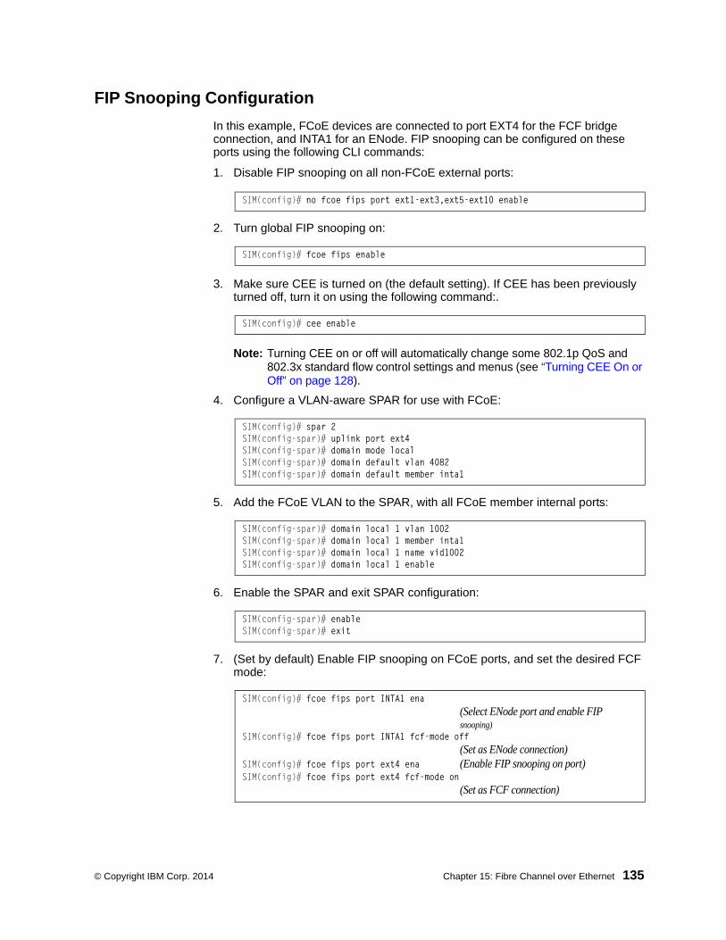
© Copyright IBM Corp. 2014 Chapter 15: Fibre Channel over Ethernet 135
FIP Snooping Configuration
In this example, FCoE devices are connected to port EXT4 for the FCF bridge connection, and INTA1 for an ENode. FIP snooping can be configured on these ports using the following CLI commands:
1. Disable FIP snooping on all non-FCoE external ports:
2. Turn global FIP snooping on:
3. Make sure CEE is turned on (the default setting). If CEE has been previously turned off, turn it on using the following command:.
Note: Turning CEE on or off will automatically change some 802.1p QoS and 802.3x standard flow control settings and menus (see “Turning CEE On or Off” on page 128).
4. Configure a VLAN-aware SPAR for use with FCoE:
5. Add the FCoE VLAN to the SPAR, with all FCoE member internal ports:
6. Enable the SPAR and exit SPAR configuration:
7. (Set by default) Enable FIP snooping on FCoE ports, and set the desired FCF mode:
SIM(config)# no fcoe fips port ext1-ext3,ext5-ext10 enable
SIM(config)# fcoe fips enable
SIM(config)# cee enable
SIM(config)# spar 2SIM(config-spar)# uplink port ext4SIM(config-spar)# domain mode localSIM(config-spar)# domain default vlan 4082SIM(config-spar)# domain default member inta1
SIM(config-spar)# domain local 1 vlan 1002SIM(config-spar)# domain local 1 member inta1SIM(config-spar)# domain local 1 name vid1002SIM(config-spar)# domain local 1 enable
SIM(config-spar)# enableSIM(config-spar)# exit
SIM(config)# fcoe fips port INTA1 ena(Select ENode port and enable FIP snooping)
SIM(config)# fcoe fips port INTA1 fcf-mode off(Set as ENode connection)
SIM(config)# fcoe fips port ext4 ena (Enable FIP snooping on port)SIM(config)# fcoe fips port ext4 fcf-mode on
(Set as FCF connection)

136 SI4093 10Gb System Interconnect Module: Application Guide
Priority-Based Flow Control
Priority-based Flow Control (PFC) is defined in IEEE 802.1Qbb. PFC extends the IEEE 802.3x standard flow control mechanism. Under standard flow control, when a port becomes busy, the SI4093 manages congestion by pausing all the traffic on the port, regardless of the traffic type. PFC provides more granular flow control, allowing the SI4093 to pause specified types of traffic on the port, while other traffic on the port continues.
PFC pauses traffic based on 802.1p priority values in the VLAN tag. The administrator can assign different priority values to different types of traffic and then enable PFC for up to two specific priority values: priority value 3, and one other. The configuration can be applied on a port-by-port basis, or globally for all ports on the SI4093. Then, when traffic congestion occurs on a port (caused when ingress traffic exceeds internal buffer thresholds), only traffic with priority values where PFC is enabled is paused. Traffic with priority values where PFC is disabled proceeds without interruption but may be subject to loss if port ingress buffers become full.
Although PFC is useful for a variety of applications, it is required for FCoE implementation where storage (SAN) and networking (LAN) traffic are converged on the same Ethernet links. Typical LAN traffic tolerates Ethernet packet loss that can occur from congestion or other factors, but SAN traffic must be lossless and requires flow control.
For FCoE, standard flow control would pause both SAN and LAN traffic during congestion. While this approach would limit SAN traffic loss, it could degrade the performance of some LAN applications that expect to handle congestion by dropping traffic. PFC resolves these FCoE flow control issues. Different types of SAN and LAN traffic can be assigned different IEEE 802.1p priority values. PFC can then be enabled for priority values that represent SAN and LAN traffic that must be paused during congestion, and disabled for priority values that represent LAN traffic that is more loss-tolerant.
PFC requires CEE to be turned on (“Turning CEE On or Off” on page 128). When CEE is turned on, PFC is enabled on priority value 3 by default. Optionally, the administrator can also enable PFC on one other priority value, providing lossless handling for another traffic type, such as for a business-critical LAN application.
Note: For any given port, only one flow control method can be implemented at any given time: either PFC or standard IEEE 802.3x flow control.

© Copyright IBM Corp. 2014 Chapter 15: Fibre Channel over Ethernet 137
Global vs. Port-by-Port PFC Configuration
PFC requires CEE to be turned on (“Turning CEE On or Off” on page 128). When CEE is turned on, standard flow control is disabled on all ports, and PFC is enabled on all ports for 802.1p priority value 3. This default is chosen because priority value 3 is commonly used to identify FCoE traffic in a CEE environment and must be guaranteed lossless behavior. PFC is disabled for all other priority values by default, but can be enabled for one additional priority value.
The administrator can also configure PFC on a port-by-port basis. The method used will typically depend on the following:
• Port-by-port PFC configuration is desirable in most mixed environments where some SI4093 ports are connected to CEE-capable (FCoE) switches, gateways, and Converged Network Adapters (CNAs), and other SI4093 ports are connected to non-CEE Layer 2/Layer 3 switches, routers and Network Interface Cards (NICs).
• Global PFC configuration is preferable in networks that implement end-to-end CEE devices. For example, if all ports are involved with FCoE and can use the same SAN and LAN priority value configuration with the same PFC settings, global configuration is easy and efficient.
• Global PFC configuration can also be used in some mixed environments where traffic with PFC-enabled priority values occurs only on ports connected to CEE devices, and not on any ports connected to non-CEE devices. In such cases, PFC can be configured globally on specific priority values even though not all ports make use them.
• PFC is not restricted to CEE and FCoE networks. In any LAN where traffic is separated into different priorities, PFC can be enabled on priority values for loss-sensitive traffic. If all ports have the same priority definitions and utilize the same PFC strategy, PFC can be globally configured.
Note: When using global PFC configuration in conjunction with the ETS feature (see “Enhanced Transmission Selection” on page 140), ensure that only pause-tolerant traffic (such as lossless FCoE traffic) is assigned priority values where PFC is enabled. Pausing other types of traffic can have adverse effects on LAN applications that expect uninterrupted traffic flow and tolerate dropping packets during congestion. Use PFC globally only if all priority values assigned for lossless traffic on one or more ports does not carry loss-tolerant traffic on other ports.

138 SI4093 10Gb System Interconnect Module: Application Guide
PFC Configuration Example
Note: DCBX may be configured to permit sharing or learning PFC configuration with or from external devices. This example assumes that PFC configuration is being performed manually. See “Data Center Bridging Capability Exchange” on page 146 for more information on DCBX.
This example is consistent with the network shown in Figure on page 126. In this example, the following topology is used.
In this example, PFC is to facilitate lossless traffic handling for FCoE (priority value 3) and a business-critical LAN application (priority value 4).
Table 18. Port-Based PFC Configuration
SI4093Port
802.1pPriority Usage
PFCSetting
EXT5 0-2 LAN Disabled
3 (not used) Enabled
4 Business-critical LAN Enabled
others (not used) Disabled
EXT4 3 FCoE (to FCF bridge) Enabled
others (not used) Disabled
INTA1 3 FCoE Enabled
others (not used) Disabled
INTA2 0-2 LAN Disabled
3 (not used) Enabled
4 Business-critical LAN Enabled
others (not used) Disabled

© Copyright IBM Corp. 2014 Chapter 15: Fibre Channel over Ethernet 139
Assuming that CEE is off (the SI4093 default), the example topology shown in Table 18 on page 138 can be configured using the following commands:
1. Turn CEE on.
2. Enable PFC for the FCoE traffic.
Note: PFC is enabled on priority 3 by default. If using the defaults, the manual configuration commands shown in this step are not necessary.
3. Enable PFC for the business-critical LAN application:
4. Save the configuration.
SIM(config)# cee enable
SIM(config)# cee port INTA1 pfc (Turn on PFC for port) INTA1)SIM(config)# cee port INTA1 pfc priority 3 enable
(Select and enable FCoE priority 3 PFC for the port)SIM(config)# cee port INTA1 pfc priority 3 description "FCoE"
(Set priority description—optional)
SIM(config)# cee port EXT4 pfc (Select and enable FCoE for port EXT4)SIM(config)# cee port EXT4 pfc priority 3 enable
(Select and enable FCoE priority 3 PFC for the port)SIM(config)# cee port EXT4 pfc priority 3 description "FCoE"
(Set priority description—optional)
SIM(config)# cee port INTA2 pfc (Turn on PFC for port) INTA2)SIM(config)# cee port INTA2 pfc priority 4 enable
(Select and enable FCoE priority 4 PFC for the port)SIM(config)# cee port INTA2 pfc priority 4 description "Business-critical LAN"
(Set priority description—optional)
SIM(config)# cee port EXT5 pfc (Select and enable FCoE for port EXT5)SIM(config)# cee port EXT5 pfc priority 4 enable
(Select and enable FCoE priority 4 PFC for the port)SIM(config)# cee port EXT5 pfc priority 4 description "Business-critical LAN"
(Set priority description—optional)
SIM(config)# copy running-config startup-config

140 SI4093 10Gb System Interconnect Module: Application Guide
Enhanced Transmission Selection
Enhanced Transmission Selection (ETS) is defined in IEEE 802.1Qaz. ETS provides a method for allocating port bandwidth based on 802.1p priority values in the VLAN tag. Using ETS, different amounts of link bandwidth can specified for different traffic types (such as for LAN, SAN, and management).
ETS is an essential component in a CEE environment that carries different types of traffic, each of which is sensitive to different handling criteria, such as Storage Area Networks (SANs) that are sensitive to packet loss, and LAN applications that may be latency-sensitive. In a single converged link, such as when implementing FCoE, ETS allows SAN and LAN traffic to coexist without imposing contrary handling requirements upon each other.
The ETS feature requires CEE to be turned on (see “Turning CEE On or Off” on page 128).
802.1p Priority Values
Under the 802.1p standard, there are eight available priority values, with values numbered 0 through 7, which can be placed in the priority field of the 802.1Q VLAN tag:
Servers and other network devices may be configured to assign different priority values to packets belonging to different traffic types (such as SAN and LAN).
ETS uses the assigned 802.1p priority values to identify different traffic types. The various priority values are assigned to priority groups (PGID), and each priority group is assigned a portion of available link bandwidth.
Priorities values within in any specific ETS priority group are expected to have similar traffic handling requirements with respect to latency and loss.
802.1p priority values may be assigned by the administrator for a variety of purposes. However, when CEE is turned on, the SI4093 sets the initial default values for ETS configuration as follows:
Figure 12. Default ETS Priority Groups
16 bits 3 bits 1 12 bits
Tag Protocol ID (0x8100) Priority CFI
VLAN ID
0 15 16 32
802.1pPriorityTypical Traffic Type
LANLAN
Latency-Sensitive LANLatency-Sensitive LANLatency-Sensitive LANLatency-Sensitive LAN
LANSAN
PGID
01234567
0
1
2
BandwidthAllocation
10%
50%
40%

© Copyright IBM Corp. 2014 Chapter 15: Fibre Channel over Ethernet 141
In the assignment model shown in Figure 12 on page 140, priorities values 0 through 2 are assigned for regular Ethernet traffic, which has “best effort” transport characteristics.
Priority 3 is typically used to identify FCoE (SAN) traffic.
Priorities 4-7 are typically used for latency sensitive traffic and other important business applications. For example, priority 4 and 5 are often used for video and voice applications such as IPTV, Video on Demand (VoD), and Voice over IP (VoIP). Priority 6 and 7 are often used for traffic characterized with a “must get there” requirement, with priority 7 used for network control which is requires guaranteed delivery to support configuration and maintenance of the network infrastructure.
Note: The default assignment of 802.1p priority values on the SI4093 changes depending on whether CEE is on or off. See “Turning CEE On or Off” on page 128 for details.
Priority Groups
For ETS use, each 801.2p priority value is assigned to a priority group which can then be allocated a specific portion of available link bandwidth. To configure a priority group, the following is required:
• CEE must be turned on (“Turning CEE On or Off” on page 128) for the ETS feature to function.
• A priority group must be assigned a priority group ID (PGID), one or more 802.1p priority values, and allocated link bandwidth greater than 0%.
PGID
Each priority group is identified with number (0 through 7, and 15) known as the PGID.
PGID 0 through 7 may each be assigned a portion of the available bandwidth.
PGID 8 through 14 are reserved as per the 802.1Qaz ETS standard.
PGID 15 is a strict priority group. It is generally used for critical traffic, such as network management. Any traffic with priority values assigned to PGID 15 is permitted as much bandwidth as required, up to the maximum available on the SI4093. After serving PGID 15, any remaining link bandwidth is shared among the other groups, divided according to the configured bandwidth allocation settings.
All 802.1p priority values assigned to a particular PGID should have similar traffic handling requirements. For example, PFC-enabled traffic should not be grouped with non-PFC traffic. Also, traffic of the same general type should be assigned to the same PGID. Splitting one type of traffic into multiple 802.1p priorities, and then assigning those priorities to different PGIDs may result in unexpected network behavior.
Each 802.1p priority value may be assigned to only one PGID. However, each PGID may include multiple priority values. Up to eight PGIDs may be configured at any given time.

142 SI4093 10Gb System Interconnect Module: Application Guide
Assigning Priority Values to a Priority Group
Each priority group may be configured from its corresponding ETS Priority Group and assigned 802.1p priority values using the following command:
where priority list is one or more 802.1p priority values (with each separated by a space). For example, to assign priority values 0 through 2 to PGID 0:
Note: Within any specific PGID, the PFC settings (see “Priority-Based Flow Control” on page 136) should be the same (enabled or disabled) for all priority values within the group. PFC can be enabled only on priority value 3 and one other priority. If the PFC setting is inconsistent within a PGID, a warning message is reported when attempting to apply the configuration.
When assigning priority values to a PGID, the specified priority value will be automatically removed from its old group and assigned to the new group when the configuration is applied.
Each priority value must be assigned to a PGID. Priority values may not be deleted or unassigned. To remove a priority value from a PGID, it must be moved to another PGID.
For PGIDs 0 through 7, bandwidth allocation can also be configured through the ETS Priority Group menu. See for “Allocating Bandwidth” on page 143 for details.
Deleting a Priority Group
A priority group is automatically deleted when it contains no associated priority values, and its bandwidth allocation is set to 0%.
Note: The total bandwidth allocated to PGID 0 through 7 must equal exactly 100%. Reducing the bandwidth allocation of any group will require increasing the allocation to one or more of the other groups (see “Allocating Bandwidth” on page 143).
SIM(config)# cee global ets priority-group pgid <priority group number (0-7, or 15)> prio <priority list>
SIM(config)# cee global ets priority-group pgid 0 prio 0 1 2

© Copyright IBM Corp. 2014 Chapter 15: Fibre Channel over Ethernet 143
Allocating Bandwidth
Allocated Bandwidth for PGID 0 Through 7
The administrator may allocate a portion of the available bandwidth to PGIDs 0 through 7. Available bandwidth is defined as the amount of link bandwidth that remains after priorities within PGID 15 are serviced (see “Unlimited Bandwidth for PGID 15” on page 143), and assuming that all PGIDs are fully subscribed. If any PGID does not fully consume its allocated bandwidth, the unused portion is made available to the other priority groups.
Priority group bandwidth allocation can be configured using the following command:
where bandwidth allocation represents the percentage of link bandwidth, specified as a number between 0 and 100, in 1% increments.
The following bandwidth allocation rules apply:
• Bandwidth allocation must be 0% for any PGID that has no assigned 802.1p pri-ority values.
• Any PGID assigned one or more priority values must have a bandwidth allocation greater than 0%.
• Total bandwidth allocation for groups 0 through 7 must equal exactly 100%. Increasing or reducing the bandwidth allocation of any PGID also requires adjusting the allocation of other PGIDs to compensate.
If these conditions are not met, the SI4093 will report an error when applying the configuration.
To achieve a balanced bandwidth allocation among the various priority groups, packets are scheduled according to a weighted deficit round-robin (WDRR) algorithm. WDRR is aware of packet sizes, which can vary significantly in a CEE environment, making WDRR more suitable than a regular weighted round-robin (WRR) method, which selects groups based only on packet counts.
Note: Actual bandwidth used by any specific PGID may vary from configured values by up to 10% of the available bandwidth in accordance with 802.1Qaz ETS standard. For example, a setting of 10% may be served anywhere from 0% to 20% of the available bandwidth at any given time.
Unlimited Bandwidth for PGID 15
PGID 15 is permitted unlimited bandwidth and is generally intended for critical traffic (such as SI4093 management). Traffic in this group is given highest priority and is served before the traffic in any other priority group.
If PGID 15 has low traffic levels, most of the system’s bandwidth will be available to serve priority groups 0 through 7. However, if PGID 15 consumes a larger part of the system’s total bandwidth, the amount available to the other groups is reduced.
Note: Consider traffic load when assigning priority values to PGID 15. Heavy traffic in this group may restrict the bandwidth available to other groups.
SIM(config)# cee global ets priority-group pgid <priority group number> bandwidth <bandwidth allocation (0-100)>

144 SI4093 10Gb System Interconnect Module: Application Guide
Configuring ETS
Consider an example consistent with that used for port-based PFC configuration (on page 138):
The example shown in Table 19 is only slightly different than the default configuration shown in Figure 12 on page 140. In this example, latency-sensitive LAN traffic (802.1p priority 5 through 6) are moved from priority group 2 to priority group 3. This leaves Business Critical LAN traffic (802.1p priority 4) in priority group 2 by itself. Also, a new group for network management traffic has been assigned. Finally, the bandwidth allocation for priority groups 1, 2, and 3 are revised.
Note: DCBX may be configured to permit sharing or learning PFC configuration with or from external devices. This example assumes that PFC configuration is being performed manually. See “Data Center Bridging Capability Exchange” on page 146 for more information on DCBX.
This example can be configured using the following commands:
1. Turn CEE on.
Table 19. ETS Configuration
Priority Usage PGID Bandwidth
0 LAN (best effort delivery)
0 10%1 LAN (best effort delivery)
2 LAN (best effort delivery)
3 SAN (Fibre Channel over Ethernet, with PFC) 1 20%
4 Business Critical LAN (lossless Ethernet, with PFC)
2 30%
5 Latency-sensitive LAN3 40%
6 Latency-sensitive LAN
7 Network Management (strict) 15 unlimited
SIM(config)# cee enable

© Copyright IBM Corp. 2014 Chapter 15: Fibre Channel over Ethernet 145
2. Configure each allocated priority group with a description (optional), list of 802.1p priority values, and bandwidth allocation:
3. Configure the strict priority group with a description (optional) and a list of 802.1p priority values:
Note: Priority group 15 is permitted unlimited bandwidth. As such, the commands for priority group 15 do not include bandwidth allocation.
4. Save the configuration.
SIM(config)# cee global ets priority-group pgid 0 description "Regular Lan"(Select a group for regular LAN) and set a groupdescription—optional)
SIM(config)# cee global ets priority-group pgid 0 bandwidth 10(Restrict to 10% of link bandwidth)
SIM(config)# cee global ets priority-group pgid 0 prio 0,1,2(Set 802.1p priority 0, 1, and 2)
SIM(config)# cee global ets priority-group pgid 1 bandwidth 20(Select a group for SAN traffic and restrict 20%of link bandwidth))
SIM(config)# cee global ets priority-group pgid 1 desc "SAN"(Set a group description—optional)
SIM(config)# cee global ets priority-group pgid 1 prio 3(Set 802.1p priority 3 for the group)
SIM(config)# cee global ets priority-group pgid 2 bandwidth 30(Select a group for latency traffic and restrict 30%of link bandwidth)
SIM(config)# cee global ets priority-group pgid 2 desc "Business Critical LAN"(Set a group description—optional)SIM(config)# cee global ets priority-group pgid 2 prio 4
(Set 802.1p priority 4)
SIM(config)# cee global ets priority-group pgid 15 priority 7 (Select a group for strict traffic and set 802.1p priority 7)
SIM(config)# cee global ets priority-group pgid 15desc "Network Management"(Set a group description—optional)
SIM(config)# copy running-config startup-config

146 SI4093 10Gb System Interconnect Module: Application Guide
Data Center Bridging Capability Exchange
Data Center Bridging Capability Exchange (DCBX) protocol is a vital element of CEE. DCBX allows peer CEE devices to exchange information about their advanced capabilities. Using DCBX, neighboring network devices discover their peers, negotiate peer configurations, and detect misconfigurations.
DCBX provides two main functions on the SI4093:
• Peer information exchange
The SI4093 uses DCBX to exchange information with connected CEE devices. For normal operation of any FCoE implementation on the SI4093, DCBX must remain enabled on all ports participating in FCoE.
• Peer configuration negotiation
DCBX also allows CEE devices to negotiate with each other for the purpose of automatically configuring advanced CEE features such as PFC, ETS, and (for some CNAs) FIP. The administrator can determine which CEE feature settings on the SI4093 are communicated to and matched by CEE neighbors, and also which CEE feature settings on the SI4093 may be configured by neighbor requirements.
The DCBX feature requires CEE to be turned on (see “Turning CEE On or Off” on page 128).
DCBX Settings
When CEE is turned on, DCBX is enabled for peer information exchange on all ports. For configuration negotiation, the following default settings are configured:
• Application Protocol: FCoE and FIP snooping is set for traffic with 802.1p priority 3
• PFC: Enabled on 802.1p priority 3
• ETS
– Priority group 0 includes priority values 0 through 2, with bandwidth allocation of 10%
– Priority group 1 includes priority value 3, with bandwidth allocation of 50%
– Priority group 2 includes priority values 4 through 7, with bandwidth allocation of 40%

© Copyright IBM Corp. 2014 Chapter 15: Fibre Channel over Ethernet 147
Enabling and Disabling DCBX
When CEE is turned on, DCBX can be enabled and disabled on a per-port basis, using the following commands:
When DCBX is enabled on a port, Link Layer Detection Protocol (LLDP) is used to exchange DCBX parameters between CEE peers. Also, the interval for LLDP transmission time is set to one second for the first five initial LLDP transmissions, after which it is returned to the administratively configured value. The minimum delay between consecutive LLDP frames is also set to one second as a DCBX default.
Peer Configuration Negotiation
CEE peer configuration negotiation can be set on a per-port basis for a number of CEE features. For each supported feature, the administrator can configure two independent flags:
• The advertise flag
When this flag is set for a particular feature, the SI4093 settings will be transmit to the remote CEE peer. If the peer is capable of the feature, and willing to accept the SI4093 settings, it will be automatically reconfigured to match the SI4093.
• The willing flag
Set this flag when required by the remote CEE peer for a particular feature as part of DCBX signaling and support. Although some devices may also expect this flag to indicate that the SI4093 will accept overrides on feature settings, the SI4093 retains its configured settings. As a result, the administrator should configure the feature settings on the SI4093 to match those expected by the remote CEE peer.
These flags are available for the following CEE features:
• Application Protocol
DCBX exchanges information regarding FCoE and FIP snooping, including the 802.1p priority value used for FCoE traffic. The advertise flag is set or reset using the following commands:
The willing flag is set or reset using the following commands:
SIM(config)# cee port <port alias or number> dcbx enable
-or-SIM(config)# no cee port <port alias or number> dcbx enable
SIM(config)# cee port <port alias or number> dcbx app_proto advertise
SIM(config)# no cee port <port alias or number> dcbx app_proto advertise
SIM(config)# cee port <port alias or number> dcbx app_proto willing
SIM(config)# no cee port <port alias or number> dcbx app_proto willing

148 SI4093 10Gb System Interconnect Module: Application Guide
• PFC
DCBX exchanges information regarding whether PFC is enabled or disabled on the port. The advertise flag is set or reset using the following commands:
The willing flag is set or reset using the following commands:
• ETS
DCBX exchanges information regarding ETS priority groups, including their 802.1p priority members and bandwidth allocation percentages. The advertise flag is set or reset using the following command:
The willing flag is set or reset using the following command:
Configuring DCBX
Consider an example consistent Figure on page 126 and used with the previous FCoE examples in this chapter:
• FCoE is used on ports INTA1 and EXT4.• CEE features are also used with LANs on ports INTA2 and EXT5.• All other ports are disabled or are connected to regular (non-CEE) LAN devices.
In this example, the SI4093 acts as the central point for CEE configuration. FCoE-related ports will be configured for advertising CEE capabilities, but not to accept external configuration. Other LAN ports that use CEE features will also be configured to advertise feature settings to remote peers, but not to accept external configuration. DCBX will be disabled on all non-CEE ports.
SIM(config)# cee port <port alias or number> dcbx pfc advertise
SIM(config)# no cee port <port alias or number> dcbx pfc advertise
SIM(config)# cee port <port alias or number> dcbx pfc willing
SIM(config)# no cee port <port alias or number> dcbx pfc willing
>> # /cfg/cee/port <port alias or number>/dcbx/etsadv {ena|dis}
>> # /cfg/cee/port <port alias or number>/dcbx/etswill {ena|dis}

© Copyright IBM Corp. 2014 Chapter 15: Fibre Channel over Ethernet 149
This example can be configured using the following commands:
1. Turn CEE on.
2. Enable desired DCBX configuration negotiation on FCoE ports:
Note: To verify DCBX settings for each port, use the cur command:
3. Enable desired DCBX advertisements on other CEE ports:
4. Disable DCBX for each non-CEE port as appropriate:
5. Save the configuration.
SIM(config)# cee enable
SIM(config)# cee port INTA1 dcbx enableSIM(config)# cee port INTA1 dcbx app advSIM(config)# cee port INTA1 dcbx pfc advSIM(config)# cee port INTA1 dcbx ets adv
SIM(config)# cee port EXT4 dcbx enableSIM(config)# cee port EXT4 dcbx app advSIM(config)# cee port EXT4 dcbx pfc advSIM(config)# cee port EXT4 dcbx ets adv
SIM(config)# show cee port INTA1 dcbx
Current DCBX Configuration on port INTA1:
Alias Port DCBX State Feature State Willing Advertise===== ==== ========== =========== ========= ========= =========INTA1 1 Enabled ETS Disabled Disabled EnabledINTA1 1 Enabled PFC Enabled Disabled EnabledINTA1 1 Enabled App Proto Disabled Disabled Enabled
SIM(config)# cee port INTA2 dcbx enableSIM(config)# cee port INTA2 dcbx app SIM(config)# cee port INTA2 dcbx pfc advSIM(config)# cee port INTA2 dcbx ets adv
SIM(config)# cee port EXT5 dcbx enableSIM(config)# cee port EXT5 dcbx app advSIM(config)# cee port EXT5 dcbx pfc advSIM(config)# cee port EXT5 dcbx ets adv
SIM(config)# no cee port INTA3 dcbx enableSIM(config)# no cee port INTA4 dcbx enable...SIM(config)# no cee port EXT11 dcbx enable
SIM(config)# copy running-config startup-config

150 SI4093 10Gb System Interconnect Module: Application Guide
FCoE Example Configuration
The following example collects the various components from previous sections of this chapter.
Figure 13. A Mixed Fibre Channel and FCoE Network
In Figure 13 on page 150, the Fibre Channel network is connected to the FCoE network through an FCF bridge module on port EXT4. The FCoE-enabled SI4093 is internally connected to a blade server (ENode) through an FCoE-enabled CNA on port INTA1. All participating ports are members of the same VLAN-aware SPAR.
1. Disable FIP snooping on all non-FCoE external ports:
2. Turn global FIP snooping on:
3. Make sure CEE is turned on (the default setting). If CEE has been previously turned off, turn it on using the following command:.
Note: Turning CEE on or off will automatically change some 802.1p QoS and 802.3x standard flow control settings (see “Turning CEE On or Off” on page 128).
4. Configure a VLAN-aware SPAR for use with FCoE:
5. Add the FCoE VLAN to the SPAR, with all FCoE member internal ports:
SIM(config)# no fcoe fips port ext1-ext3,ext5-ext10 enable
SIM(config)# fcoe fips enable
SIM(config)# cee enable
SIM(config)# spar 2SIM(config-spar)# uplink port ext4SIM(config-spar)# domain mode localSIM(config-spar)# domain default vlan 4082SIM(config-spar)# domain default member inta1
SIM(config-spar)# domain local 1 vlan 1002SIM(config-spar)# domain local 1 member inta1SIM(config-spar)# domain local 1 name vid1002SIM(config-spar)# domain local 1 enable
SI4093
Servers IBM Chassis
EXT5
EXT4INTA1
INTA20-24
LANBusiness-Critical LAN
802.1p Priority & Usage
3 FCoE Applications802.1p Priority & Usage
FCoE
CNA
CNA LAN
FibreChannelFCF

© Copyright IBM Corp. 2014 Chapter 15: Fibre Channel over Ethernet 151
6. Enable the SPAR and exit SPAR configuration:
7. Enable FIP snooping on FCoE ports, and set the desired FCF mode:
8. (Set by default) Enable PFC for the FCoE traffic.
9. Enable PFC for the business-critical LAN application:
SIM(config-spar)# enableSIM(config-spar)# exit
SIM(config-VLAN)# fcoe fips port INTA1 enable(Select ENode port and enable FIPsnooping on port)
SIM(config-VLAN)# fcoe fips port INTA1 fcfmode off(Set as ENode connection)
SIM(config-VLAN)# fcoe fips port EXT4 enable(Select FCF module port A and enable FIPsnooping on port)
SIM(config-VLAN)# fcoe fips port EXT4 fcfmode on(Set as FCF connection)
SIM(config)# cee port INTA1 pfc (Turn on PFC for port) INTA1)SIM(config)# cee port INTA1 pfc priority 3 enable
(Select and enable FCoE priority 3 PFC for the port)SIM(config)# cee port INTA1 pfc priority 3 description "FCoE"
(Set priority description—optional)
SIM(config)# cee port EXT4 pfc (Select and enable FCoE for port EXT4)SIM(config)# cee port EXT4 pfc priority 3 enable
(Select and enable FCoE priority 3 PFC for the port)SIM(config)# cee port EXT4 pfc priority 3 description "FCoE"
(Set priority description—optional)
SIM(config)# cee port INTA2 pfc (Turn on PFC for port) INTA2)SIM(config)# cee port INTA2 pfc priority 4 enable
(Select and enable FCoE priority 4 PFC for the port)SIM(config)# cee port INTA2 pfc priority 4 description "Business-critical LAN"
(Set priority description—optional)
SIM(config)# cee port EXT5 pfc (Select and enable FCoE for port EXT5)SIM(config)# cee port EXT5 pfc priority 4 enable
(Select and enable FCoE priority 4 PFC for the port)SIM(config)# cee port EXT5 pfc priority 4 description "Business-critical LAN"
(Set priority description—optional)

152 SI4093 10Gb System Interconnect Module: Application Guide
10. For ETS, allocate bandwidth for each priority group:
Note: Do not place PFC-enabled traffic queues and non-PFC traffic queues in the same priority group, as this may result in unexpected network behavior.
11. Configure the strict priority group:
12. Enable desired DCBX configuration negotiation on FCoE ports:
13. Enable desired DCBX advertisements on other CEE ports:
SIM(config)# cee global ets priority-group pgid 0 bandwidth 10(Select a group for regular LAN and restrict to 10% of link bandwidth)
SIM(config)# cee global ets priority-group pgid 0 prio 0,1,2(Set 802.1p priority 0, 1, and 2)
SIM(config)# cee global ets priority-group pgid 1 bandwidth 20(Select a group for SAN traffic and restrict 20%of link bandwidth))
SIM(config)# cee global ets priority-group pgid 1 prio 3(Set 802.1p priority 3 for the group)
SIM(config)# cee global ets priority-group pgid 2 bandwidth 30(Select a group for latency traffic and restrict 30%of link bandwidth)
SIM(config)# cee global ets priority-group pgid 2 prio 4(Set 802.1p priority 4)
SIM(config)# cee global ets priority-group pgid 3 bandwidth 40(Select a group for latency traffic and restrict 40%of link bandwidth)
SIM(config)# cee global ets priority-group pgid 3 prio 5,6(Set 802.1p priorities 5 and 6)
SIM(config)# cee global ets priority-group pgid 15 priority 7 (Select a group for strict traffic and set 802.1p priority 7)
SIM(config)# cee port INTA1 dcbx enableSIM(config)# cee port INTA1 dcbx app advSIM(config)# cee port INTA1 dcbx pfc advSIM(config)# cee port INTA1 dcbx ets adv
SIM(config)# cee port EXT4 dcbx enableSIM(config)# cee port EXT4 dcbx app advSIM(config)# cee port EXT4 dcbx pfc advSIM(config)# cee port EXT4 dcbx ets adv
SIM(config)# cee port INTA2 dcbx enableSIM(config)# cee port INTA2 dcbx app SIM(config)# cee port INTA2 dcbx pfc advSIM(config)# cee port INTA2 dcbx ets adv
SIM(config)# cee port EXT5 dcbx enableSIM(config)# cee port EXT5 dcbx app advSIM(config)# cee port EXT5 dcbx pfc advSIM(config)# cee port EXT5 dcbx ets adv

© Copyright IBM Corp. 2014 Chapter 15: Fibre Channel over Ethernet 153
14. Disable DCBX for each non-CEE port as appropriate:
15. Save the configuration.
SIM(config)# no cee port INTA3 dcbx enableSIM(config)# no cee port INTA4 dcbx enable...SIM(config)# no cee port EXT11 dcbx enable
SIM(config)# copy running-config startup-config

154 SI4093 10Gb System Interconnect Module: Application Guide

© Copyright IBM Corp. 2014 Chapter 16: Service Location Protocol 155
Chapter 16. Service Location Protocol
Service Location Protocol (SLP) allows the switch to provide dynamic directory services that helps users find servers by attributes rather than by name or address. SLP eliminates the need for a user to know the name of a network host supporting a service. SLP allows the user to bind a service description to the network address of the service.
Service Location Protocol is described in RFC 2608.
Note: SLP is not supported on the internal management port (MGT).
SLP defines specialized components called agents that perform tasks and support services as follows:
• User Agent (UA) supports service query functions. It requests service information for user applications. The User Agent retrieves service information from the Service Agent or Directory Agents. A Host On-Demand client is an example of a User Agent.
• Service Agent (SA) provides service registration and service advertisement. Note: In this release, SA supports UA/DA on Linux with SLPv2 support.
• Directory Agent (DA) collects service information from Service Agents to provide a repository of service information in order to centralize it for efficient access by User Agents. There can only be one Directory Agent present per given host.
The Directory Agent acts as an intermediate tier in the SLP architecture, placed between the User Agents and the Service Agents, so they communicate only with the Directory Agent instead of with each other. This eliminates a large portion of the multicast request or reply traffic on the network, and it protects the Service Agents from being overwhelmed by too many service requests.
Services are described by the configuration of attributes associated with a type of service. A User Agent can select an appropriate service by specifying the attributes that it needs in a service request message. When service replies are returned, they contain a Uniform Resource Locator (URL) pointing to the service desired, and other information, such as server load, needed by the User Agent.

156 SI4093 10Gb System Interconnect Module: Application Guide
Active DA Discovery
When a Service Agent or User Agent initializes, it can perform Active Directory Agent Discovery using a multicast service request and specifies the special, reserved service type (service:directory-agent). Active DA Discovery is achieved through the same mechanism as any other discovery using SLP.
The Directory Agent replies with unicast service replies, which provides the URLs and attributes of the requested service.
SLP Configuration
Use the following CLI commands to configure SLP for the switch:
Table 20. SLP Commands
Command Syntax and Usage
[no] ip slp enable
Enables or disables SLP on the switch.
Command mode: Global configuration
[no] ip slp active-da-discovery enable
Enables or disables Active DA Discovery.
Command mode: Global configuration
ip slp active-da-discovery-start-wait-time <1-10>
Configures the wait time before starting Active DA Discovery, in seconds.
The default value is 3 seconds.
Command mode: Global configuration
clear ip slp directory-agentsClears all Directory Agents learned by the switch.
Command mode: Global configuration

© Copyright IBM Corp. 2014 157
Chapter 17. Layer 2 Failover (Manual Monitor)
The primary application for Layer 2 Failover is to support Network Adapter Teaming. With Network Adapter Teaming, all the NICs on each server share the same IP address, and are configured into a team. One NIC is the primary link, and the other is a standby link. For more details, refer to the documentation for your Ethernet adapter.
Note: Only two links per server blade can be used for Layer 2 Trunk Failover (one primary and one backup). Network Adapter Teaming allows only one backup NIC for each server blade.
There are two types of Layer 2 Failover:
• Manual Monitoring (MMON)
MMON allows you to specify a set of ports and/or trunks to be monitored for link health. If a configurable number of monitored links fails, all ports specified in a control set are disabled in order to trigger NIC failover.
MMON is available both in SPAR and XPAR contexts. MMON is enabled by default.
• Automatic Monitoring (AMON)
When AMON is enabled on any trunk group, if a configurable number of member links fails, all internal ports (or those for affected VLANs if VLAN monitoring is active) are disabled in order to trigger NIC failover.
AMON is available only in the XPAR context. It does not apply to SPAR domains. For details about AMON, see “Layer 2 Failover (Auto Monitor)” on page 251.
Note: MMON and AMON failover are mutually exclusive. They cannot both be configured to operate on the SI4093 at the same time.
Manual Monitoring
MMON allows you to configure a set of external ports and/or trunks to be monitored for link failures (a monitor list), and another set of internal and/or external ports or trunks to disable when a failure trigger limit is reached (a control list). When the SI4093 detects a certain number of link failures (configurable) in the monitor list, it automatically disables all items in the control list.
Consider a scenario where a specific set of servers (attached to SI4093 internal ports) relies upon not just one external uplink port, but on the aggregate bandwidth available in a multi-port LAG. Without Layer 2 Failover, if one or more of the external ports in the LAG were to fail, the overall service capacity might become degraded even though a significant portion of the LAG remains available. In such a case, it may be preferable to force the affected servers to failover to their alternate NIC.
Layer 2 Failover helps to accomplish NIC failover. In the above scenario, the external LAG is placed on the monitor list, and the corresponding internal (server) ports are placed on the control list. Then, if a partial LAG failure occurred, the server’s active network adapters would detect the disabled internal link and trigger a network-adapter failover to an alternate port or trunk on the SI4093, or an alternate SI4093 in the chassis.
The SI4093 automatically enables the control list items when the monitor list items return to service.

158 SI4093 10Gb System Interconnect Module: Application Guide
MMON Default Settings
By default, Layer 2 Failover is enabled and pre-configured for MMON operation in SPARs based on which system license keys are installed (see “System License Keys” on page 43).
• Trigger 1
Defined automatically by factory default at all license levels:
– Monitor list: EXT1–EXT10 (in LAG 65 with LACP admin key 1000)
– Control list: Internal ports INTA1–INTA14
• Trigger 2
Defined automatically at license upgrades 1 and 2:
– Monitor list: EXT15–EXT22 (in LAG 66 with LACP admin key 1001)
– Control list: Internal ports INTB1–INTB14
• Trigger 3
Defined automatically at license upgrade 2 only:
– Monitor list: EXT11–EXT14 (in LAG 67 with LACP admin key 1002)
– Control list: Internal ports INTC1–INTC14
By default, one Layer 2 Failover trigger is configured for each available SPAR. In each trigger, the default external ports for the SPAR are placed on the monitor list, and the default internal ports for the SPAR are placed on the control list. Because the default failover limit for each trigger is 0, when there are no external ports available in the SPAR, all its internal ports are automatically disabled.
MMON Port States
Monitor Port State
A monitor port is considered operational as long as the following conditions are true:
• The port must be in the Link Up state.• If the port is part of an LACP trunk, the port must be in the Aggregated state.
If any of the above conditions is false, the monitor port is considered to have failed.
Only external ports and external LAGs can be placed on the monitor list.
Control Port State
A control port is considered Operational if the monitor trigger is up. As long as the trigger is up, the port is considered operational from a teaming perspective, even if the port itself is actually in the Down state or Not Aggregated state (if part of an LACP trunk).
A control port is considered to have failed only if the monitor trigger is in the Down state.
Internal and external ports and LAGs can be placed on the control list.

© Copyright IBM Corp. 2014 Chapter 17: Layer 2 Failover (Manual Monitor) 159
Viewing the Port Status
To view the state of any port, use one of the following commands:
Failover Limits
The failover limit lets you specify the minimum number of operational links required within each trigger before the trigger initiates a failover event. For example, if the limit is two, a failover event occurs when the number of operational links in the trigger is two or fewer.
When you set the limit to zero (the default for each trigger), the SI4093 initiates a failover event only when no links in the trigger are operational.
Layer 2 Failover with LACP
L2 Failover works with Link Aggregation Control Protocol (LACP) as follows.
Link Aggregation Control Protocol allows the switch to form trunks. You can use the admin key to add up to two LACP trunks to a failover trigger using automatic monitoring. When you add an admin key to a trigger, any LACP trunk with that admin key becomes a member of the trigger.
MMON Configuration Guidelines
This section provides important information about configuring Layer 2 Failover with MMON.
• MMON and AMON failover are mutually exclusive. They cannot both be configured to operate on the SI4093 at the same time.
• MMON can monitor only external ports. Internal ports cannot be placed on the monitor list.
• Any specific failover trigger can monitor external ports only, static trunks only, or LACP trunks only. The different types cannot be combined in the same trigger.
• Port membership for different triggers should not overlap. Any specific port should be a member of only one trigger.
Configuring MMON
Use the following procedure to configure a Layer 2 Failover Manual Monitor.
1. Specify the links to monitor.
2. Specify the links to disable when the failover limit is reached.
>> # show interface link (View port link status)>> # show lacp information (View port LACP status)
SIM(config)# failover trigger 1 mmon monitor member ext1-ext5
SIM(config)# failover trigger 1 mmon control member inta1-inta8

160 SI4093 10Gb System Interconnect Module: Application Guide
3. Configure general Failover parameters.
4. Verify the configuration.
SIM(config)# failover enable (Enable Layer 2 Failover)
SIM(config)# failover trigger 1 enable (Enable the individual trigger)
SIM(config)# failover trigger 1 limit 2 (Set the failover limit)
SIM(config)# show failover trigger 1 information

© Copyright IBM Corp. 2014 161
Chapter 18. Link Layer Discovery Protocol
The IBM Networking OS software support Link Layer Discovery Protocol (LLDP). This chapter discusses the use and configuration of LLDP on the switch:
• “LLDP Overview” on page 161
• “Enabling or Disabling LLDP” on page 162
• “LLDP Transmit Features” on page 163
• “LLDP Receive Features” on page 166
• “LLDP Example Configuration” on page 168
LLDP Overview
Link Layer Discovery Protocol (LLDP) is an IEEE 802.1AB-2005 standard for discovering and managing network devices. LLDP uses Layer 2 (the data link layer), and allows network management applications to extend their awareness of the network by discovering devices that are direct neighbors of already known devices.
With LLDP, the SI4093 can advertise the presence of its ports, their major capabilities, and their current status to other LLDP stations in the same LAN. LLDP transmissions occur on ports at regular intervals or whenever there is a relevant change to their status. The switch can also receive LLDP information advertised from adjacent LLDP-capable network devices.
In addition to discovery of network resources, and notification of network changes, LLDP can help administrators quickly recognize a variety of common network configuration problems, such as unintended VLAN exclusions or mis-matched port aggregation membership.
The LLDP transmit function and receive function can be independently configured on a per-port basis. The administrator can allow any given port to transmit only, receive only, or both transmit and receive LLDP information.
The LLDP information to be distributed by the SI4093 ports, and that which has been collected from other LLDP stations, is stored in the switch’s Management Information Base (MIB). Network Management Systems (NMS) can use Simple Network Management Protocol (SNMP) to access this MIB information. LLDP-related MIB information is read-only.
Changes, either to the local switch LLDP information or to the remotely received LLDP information, are flagged within the MIB for convenient tracking by SNMP-based management systems.
For LLDP to provide expected benefits, all network devices that support LLDP should be consistent in their LLDP configuration.

162 SI4093 10Gb System Interconnect Module: Application Guide
Enabling or Disabling LLDP
Global LLDP Setting
By default, LLDP is enabled on the SI4093. To turn LLDP off or on, use the following commands:
Transmit and Receive Control
The SI4093 can also be configured to transmit or receive LLDP information on a port-by-port basis. By default, when LLDP is globally enabled on the switch, SI4093 ports transmit and receive LLDP information (see the tx_rx option below). To change the LLDP transmit and receive state, the following commands are available:
To view the LLDP transmit and receive status, use the following commands:
SIM(config)# [no] lldp enable (Turn LLDP on or off globally)
SIM(config)# interface port <n> (Select a switch port)SIM(config-if)# lldp admin-status tx_rx (Transmit and receive LLDP)SIM(config-if)# lldp admin-status tx_only (Only transmit LLDP)SIM(config-if)# lldp admin-status rx_only (Only receive LLDP)SIM(config-if)# no lldp admin-status (Do not participate in LLDP)SIM(config-if)# exit (Exit port mode)
SIM(config)# show lldp port (status of all ports)SIM(config)# show interface port <n> lldp (status of selected port)

© Copyright IBM Corp. 2014 Chapter 18: Link Layer Discovery Protocol 163
LLDP Transmit Features
Numerous LLDP transmit options are available, including scheduled and minimum transmit interval, expiration on remote systems, SNMP trap notification, and the types of information permitted to be shared.
Scheduled Interval
The SI4093 can be configured to transmit LLDP information to neighboring devices once each 5 to 32768 seconds. The scheduled interval is global; the same interval value applies to all LLDP transmit-enabled ports. However, to help balance LLDP transmissions and keep them from being sent simultaneously on all ports, each port maintains its own interval clock, based on its own initialization or reset time. This allows switch-wide LLDP transmissions to be spread out over time, though individual ports comply with the configured interval.
The global transmit interval can be configured using the following command:
where interval is the number of seconds between LLDP transmissions. The range is 5 to 32768. The default is 30 seconds.
Minimum Interval
In addition to sending LLDP information at scheduled intervals, LLDP information is also sent when the SI4093 detects relevant changes to its configuration or status (such as when ports are enabled or disabled). To prevent the SI4093 from sending multiple LLDP packets in rapid succession when port status is in flux, a transmit delay timer can be configured.
The transmit delay timer represents the minimum time permitted between successive LLDP transmissions on a port. Any interval-driven or change-driven updates will be consolidated until the configured transmit delay expires.
The minimum transmit interval can be configured using the following command:
where interval is the minimum number of seconds permitted between successive LLDP transmissions on any port. The range is 1 to one-quarter of the scheduled transmit interval (msgtxint), up to 8192. The default is 2 seconds.
SIM(config)# lldp refresh-interval <interval>
SIM(config)# lldp transmission-delay <interval>

164 SI4093 10Gb System Interconnect Module: Application Guide
Time-to-Live for Transmitted Information
The transmitted LLDP information is held by remote systems for a limited time. A time-to-live parameter allows the switch to determine how long the transmitted data should be held before it expires. The hold time is configured as a multiple of the configured transmission interva
where multiplier is a value between 2 and 10. The default value is 4, meaning that remote systems will hold the port’s LLDP information for 4 x the 30-second msgtxint value, or 120 seconds, before removing it from their MIB.
Trap Notifications
If SNMP is enabled on the SI4093 (see “Using Simple Network Management Protocol” on page 24), each port can be configured to send SNMP trap notifications whenever LLDP transmissions are sent. By default, trap notification is disabled for each port. The trap notification state can be changed using the following commands):
In addition to sending LLDP information at scheduled intervals, LLDP information is also sent when the SI4093 detects relevant changes to its configuration or status (such as when ports are enabled or disabled). To prevent the SI4093 from sending multiple trap notifications in rapid succession when port status is in flux, a global trap delay timer can be configured.
The trap delay timer represents the minimum time permitted between successive trap notifications on any port. Any interval-driven or change-driven trap notices from the port will be consolidated until the configured trap delay expires.
The minimum trap notification interval can be configured using the following command:
where interval is the minimum number of seconds permitted between successive LLDP transmissions on any port. The range is 1 to 3600. The default is 5 seconds.
If SNMP trap notification is enabled, the notification messages can also appear in the system log. This is enabled by default. To change whether the SNMP trap notifications for LLDP events appear in the system log, use the following command
SIM(config)# lldp holdtime-multiplier <multiplier>
SIM(config)# interface port 1SIM(config-if)# [no] lldp trap-notificationSIM(config-if)# exit
SIM(config)# lldp trap-notification-interval <interval>
SIM(config)# [no] logging log lldp

© Copyright IBM Corp. 2014 Chapter 18: Link Layer Discovery Protocol 165
Changing the LLDP Transmit State
When the port is disabled, or when LLDP transmit is turned off for the port using the admstat command’s rx_only or disabled options (see “Transmit and Receive Control” on page 162), a final LLDP packet is transmitted with a time-to-live value of 0. Neighbors that receive this packet will remove the LLDP information associated with the SI4093 port from their MIB.
In addition, if LLDP is fully disabled on a port (using admstat disabled) and later re-enabled, the SI4093 will temporarily delay resuming LLDP transmissions on the port in order to allow the port LLDP information to stabilize. The reinitialization delay interval can be globally configured for all ports using the following command::
where interval is the number of seconds to wait before resuming LLDP transmissions. The range is between 1 and 10. The default is 2 seconds.
Types of Information Transmitted
When LLDP transmission is permitted on the port (see “Enabling or Disabling LLDP” on page 162), the port advertises the following required information in type/length/value (TLV) format:
• Chassis ID• Port ID• LLDP Time-to-Live
LLDP transmissions can also be configured to enable or disable inclusion of optional information, using the following command:
where type is an LLDP information option from Table 21:
SIM(config)# lldp reinit-delay <interval>
SIM(config)# interface port 1SIM(config-if)# [no] lldp tlv <type>SIM(config-if)# exit
Table 21. LLDP Optional Information Types
Type Description Default
portdesc Port Description Enabled
sysname System Name Enabled
sysdescr System Description Enabled
syscap System Capabilities Enabled
mgmtaddr Management Address Enabled
portvid IEEE 802.1 Port VLAN ID Disabled
portprot IEEE 802.1 Port and Protocol VLAN ID Disabled
vlanname IEEE 802.1 VLAN Name Disabled
protid IEEE 802.1 Protocol Identity Disabled

166 SI4093 10Gb System Interconnect Module: Application Guide
LLDP Receive Features
Types of Information Received
When the LLDP receive option is enabled on a port (see “Enabling or Disabling LLDP” on page 162), the port may receive the following information from LLDP-capable remote systems:
• Chassis Information• Port Information• LLDP Time-to-Live• Port Description• System Name• System Description• System Capabilities Supported/Enabled• Remote Management Address
The SI4093 stores the collected LLDP information in the MIB. Each remote LLDP-capable device is responsible for transmitting regular LLDP updates. If the received updates contain LLDP information changes (to port state, configuration, LLDP MIB structures, deletion), the switch will set a change flag within the MIB for convenient notification to SNMP-based management systems.
macphy IEEE 802.3 MAC/PHY Configuration/Status, including the auto-negotiation, duplex, and speed status of the port.
Disabled
powermdi IEEE 802.3 Power via MDI, indicating the capabilities and status of devices that require or provide power over twisted-pair copper links.
Disabled
linkaggr IEEE 802.3 Link Aggregation status for the port.
Disabled
framesz IEEE 802.3 Maximum Frame Size for the port.
Disabled
dcbx Data Center Bridging Capability Exchange Protocol (DCBX) for the port.
Enabled
all Select all optional LLDP information for inclusion or exclusion.
Disabled
Table 21. LLDP Optional Information Types (continued)
Type Description Default

© Copyright IBM Corp. 2014 Chapter 18: Link Layer Discovery Protocol 167
Viewing Remote Device Information
LLDP information collected from neighboring systems can be viewed in numerous ways:
• Using a centrally-connected LLDP analysis server• Using an SNMP agent to examine the SI4093 MIB• Using CLI commands on the SI4093
Using the CLI, the following command displays remote LLDP information:
To view a summary of remote information, omit the Index number parameter. For example:
To view detailed information for a remote device, specify the Index number as found in the summary. For example, in keeping with the sample summary, to list details for the first remote device (with an Index value of 1), use the following command:
Note: Received LLDP information can change very quickly. When using information commands, it is possible that flags for some expected events may be too short-lived to be observed in the output.
SIM(config)# show lldp remote-device [<index number>]
SIM(config)# show lldp remote-deviceLLDP Remote Devices Information
LocalPort | Index | Remote Chassis ID | Remote Port | Remote System Name----------|-------|----------------------|-------------|---------------------3 | 1 | 00 18 b1 33 1d 00 | 23 |
SIM(config)# show lldp remote-device 1Local Port Alias: 3 Remote Device Index : 1 Remote Device TTL : 99 Remote Device RxChanges : false Chassis Type : Mac Address Chassis Id : 00-18-b1-33-1d-00 Port Type : Locally Assigned Port Id : 23 Port Description : 7
System Name : System Description : IBM Networking OS Virtual Fabric 10Gb Switch Module for IBM BladeCenter, flash image: version 6.9.0, boot image: version 6.9.0
System Capabilities Supported : bridge, router System Capabilities Enabled : bridge, router
Remote Management Address: Subtype : IPv4 Address : 10.100.120.181 Interface Subtype : ifIndex Interface Number : 128 Object Identifier :

168 SI4093 10Gb System Interconnect Module: Application Guide
Time-to-Live for Received Information
Each remote device LLDP packet includes an expiration time. If the switch port does not receive an LLDP update from the remote device before the time-to-live clock expires, the switch will consider the remote information to be invalid, and will remove all associated information from the MIB.
Remote devices can also intentionally set their LLDP time-to-live to 0, indicating to the switch that the LLDP information is invalid and should be immediately removed.
LLDP Example Configuration1. Turn LLDP on globally.
2. Set the global LLDP timer features.
3. Set LLDP options for each port.
4. Enable syslog reporting.
5. Save the configuration.
6. Verify the configuration settings
7. View remote device information as needed.
SIM(config)# lldp enable
SIM(config)# lldp refresh-interval 30 (Transmit each 30 seconds)SIM(config)# lldp transmission-delay 2 (No more often than 2 sec.)SIM(config)# lldp holdtime-multiplier 4 (Remote hold 4 intervals)SIM(config)# lldp reinit-delay 2 (Wait 2 sec. after reinit.)SIM(config)# lldp trap-notification-interval 5(Minimum 5 sec. between)
SIM(config)# interface port <n> (Select a switch port)SIM(config-if)# lldp admin-status tx_rx (Transmit and receive LLDP)SIM(config-if)# lldp trap-notification (Enable SNMP trap notifications)SIM(config-if)# lldp tlv all (Transmit all optional information)SIM(config-if)# exit
SIM(config)# logging log lldp
SIM(config)# copy running-config startup-config
SIM(config)# show lldp
SIM(config)# show lldp remote-device
orSIM(config)# show lldp remote-device <index number>

© Copyright IBM Corp. 2014 169
Chapter 19. Simple Network Management Protocol
IBM Networking OS provides Simple Network Management Protocol (SNMP) version 1, version 2, and version 3 support for access through any network management software, such as IBM Director.
SNMP Version 1
To access the SNMP agent on the SI4093, the read and write community strings on the SNMP manager should be configured to match those on the switch. The default read community string on the switch is public and the default write community string is private.
The read and write community strings on the switch can be changed using the following commands on the CLI:
The SNMP manager should be able to reach the management interface or any one of the IP interfaces on the switch.
For the SNMP manager to receive the SNMPv1 traps sent out by the SNMP agent on the switch, configure the trap host on the switch with the following command:
SNMP Version 3
SNMP version 3 (SNMPv3) is an enhanced version of the Simple Network Management Protocol, approved by the Internet Engineering Steering Group in March, 2002. SNMPv3 contains additional security and authentication features that provide data origin authentication, data integrity checks, timeliness indicators and encryption to protect against threats such as masquerade, modification of information, message stream modification and disclosure.
SNMPv3 allows clients to query the MIBs securely.
SNMPv3 configuration is managed using the following menu:
For more information on SNMP MIBs and the commands used to configure SNMP on the switch, see the IBM Networking OS 7.8 Command Reference.
Default Configuration
IBM Networking OS has two SNMPv3 users by default. Both of the following users have access to all the MIBs supported by the switch:
• User 1 name is adminmd5 (password adminmd5). Authentication used is MD5.• User 2 name is adminsha (password adminsha). Authentication used is SHA.
SIM(config)# snmp-server read-community <1-32 characters>
-and-SIM(config)# snmp-server write-community <1-32 characters>
SIM(config)# snmp-server trap-src-if <trap source IP interface>SIM(config)# snmp-server host <IPv4 address> <trap host community string>
SIM(config)# snmp-server user <1-16> name <1-32 characters>

170 SI4093 10Gb System Interconnect Module: Application Guide
Up to 16 SNMP users can be configured on the switch. To modify an SNMP user, enter the following commands: :
Users can be configured to use the authentication/privacy options. The SI4093 support two authentication algorithms: MD5 and SHA, as specified in the following command: :
User Configuration Example
1. To configure a user with name “admin,” authentication type MD5, and authentication password of “admin,” privacy option DES with privacy password of “admin,” use the following CLI commands. .
2. Configure a user access group, along with the views the group may access. Use the access table to configure the group’s access level. .
Because the read view (rview), write view (wview), and notify view (nview) are all set to “iso,” the user type has access to all private and public MIBs.
3. Assign the user to the user group. Use the group table to link the user to a particular access group. .
If you want to allow user access only to certain MIBs, see “View-Based Configuration,” next.
SIM(config)# snmp-server user <1-16> name <1-32 characters>
SIM(config)# snmp-server user <1-16> authentication-protocol {md5|sha} authentication-password
-or-
SIM(config)# snmp-server user <1-16> authentication-protocol none
SIM(config)# snmp-server user 5 name adminSIM(config)# snmp-server user 5 authentication-protocol md5
authentication-passwordChanging authentication password; validation required: Enter current admin password: <admin. password>
Enter new authentication password: <auth. password>
Re-enter new authentication password: <auth. password>New authentication password accepted.
SIM(config)# snmp-server user 5 privacy-protocol des privacy-passwordChanging privacy password; validation required:Enter current admin password: <admin. password>
Enter new privacy password: <privacy password>
Re-enter new privacy password: <privacy password>New privacy password accepted.
SIM(config)# snmp-server access 5 name admingrpSIM(config)# snmp-server access 5 level authprivSIM(config)# snmp-server access 5 read-view isoSIM(config)# snmp-server access 5 write-view isoSIM(config)# snmp-server access 5 notify-view iso
SIM(config)# snmp-server group 5 user-name adminSIM(config)# snmp-server group 5 group-name admingrp

© Copyright IBM Corp. 2014 Chapter 19: Simple Network Management Protocol 171
Configuring SNMP Trap Hosts
SNMPv1 Trap Host
1. Configure a user with no authentication and password
2. Configure an access group and group table entries for the user. Use the following menu to specify which traps can be received by the user:
In the following example the user will receive the traps sent by the switch.
3. Configure an entry in the notify table. .
4. Specify the IPv4 address and other trap parameters in the targetAddr and targetParam tables. Use the following menus to specify the user name associated with the targetParam table: :
Note: IBM Networking OS 7.8 supports only IPv4 addresses for SNMP trap hosts.
5. Use the community table to specify which community string is used in the trap..
SIM(config)# snmp-server user 10 name v1trap
SIM(config)# snmp-server access <user number>
SIM(config)# snmp-server access 10 (Access group to view SNMPv1 traps) name v1trap security snmpv1 notify-view isoSIM(config)# snmp-server group 10 (Assign user to the access group) security snmpv1 user-name v1trap group-name v1trap
SIM(config)# snmp-server notify 10 name v1trapSIM(config)# snmp-server notify 10 tag v1trap
SIM(config)# snmp-server target-address 10 name v1trap address 10.70.70.190SIM(config)# snmp-server target-address 10 parameters-name v1paramSIM(config)# snmp-server target-address 10 taglist v1paramSIM(config)# snmp-server target-parameters 10 name v1paramSIM(config)# snmp-server target-parameters 10 user-name v1onlySIM(config)# snmp-server target-parameters 10 message snmpv1
SIM(config)# snmp-server community 10 (Define the community string) index v1trap name public user-name v1trap

172 SI4093 10Gb System Interconnect Module: Application Guide
SNMPv2 Trap Host Configuration
The SNMPv2 trap host configuration is similar to the SNMPv1 trap host configuration. Wherever you specify the model, use snmpv2 instead of snmpv1. .
Note: IBM Networking OS 7.8 supports only IPv4 addresses for SNMP trap hosts.
SIM(config)# snmp-server user 10 name v2trap
SIM(config)# snmp-server group 10 security snmpv2SIM(config)# snmp-server group 10 user-name v2trapSIM(config)# snmp-server group 10 group-name v2trapSIM(config)# snmp-server access 10 name v2trapSIM(config)# snmp-server access 10 security snmpv2SIM(config)# snmp-server access 10 notify-view iso
SIM(config)# snmp-server notify 10 name v2trapSIM(config)# snmp-server notify 10 tag v2trap
SIM(config)# snmp-server target-address 10 name v2trap address 100.10.2.1SIM(config)# snmp-server target-address 10 taglist v2trapSIM(config)# snmp-server target-address 10 parameters-name v2paramSIM(config)# snmp-server target-parameters 10 name v2paramSIM(config)# snmp-server target-parameters 10 message snmpv2cSIM(config)# snmp-server target-parameters 10 user-name v2trapSIM(config)# snmp-server target-parameters 10 security snmpv2
SIM(config)# snmp-server community 10 index v2trapSIM(config)# snmp-server community 10 user-name v2trap

© Copyright IBM Corp. 2014 Chapter 19: Simple Network Management Protocol 173
SNMPv3 Trap Host Configuration
To configure a user for SNMPv3 traps, you can choose to send the traps with both privacy and authentication, with authentication only, or without privacy or authentication.
This is configured in the access table using the following commands: :
Configure the user in the user table accordingly.
It is not necessary to configure the community table for SNMPv3 traps because the community string is not used by SNMPv3.
The following example shows how to configure a SNMPv3 user v3trap with authentication only: :
Note: IBM Networking OS 7.8 supports only IPv4 addresses for SNMP trap hosts.
SIM(config)# snmp-server access <1-32> levelSIM(config)# snmp-server target-parameters <1-16>
SIM(config)# snmp-server user 11 name v3trapSIM(config)# snmp-server user 11 authentication-protocol md5 authentication-passwordChanging authentication password; validation required: Enter current admin password: <admin. password>
Enter new authentication password: <auth. password>
Re-enter new authentication password: <auth. password>New authentication password accepted.SIM(config)# snmp-server access 11 notify-view isoSIM(config)# snmp-server access 11 level authnoprivSIM(config)# snmp-server group 11 user-name v3trapSIM(config)# snmp-server group 11 tag v3trapSIM(config)# snmp-server notify 11 name v3trapSIM(config)# snmp-server notify 11 tag v3trapSIM(config)# snmp-server target-address 11 name v3trap address 47.81.25.66SIM(config)# snmp-server target-address 11 taglist v3trapSIM(config)# snmp-server target-address 11 parameters-name v3paramSIM(config)# snmp-server target-parameters 11 name v3paramSIM(config)# snmp-server target-parameters 11 user-name v3trapSIM(config)# snmp-server target-parameters 11 level authNoPriv

174 SI4093 10Gb System Interconnect Module: Application Guide
SNMP MIBs
The IBM Networking OS SNMP agent supports SNMP version 3. Security is provided through SNMP community strings. The default community strings are “public” for SNMP GET operation and “private” for SNMP SET operation. The community string can be modified only through the Command Line Interface (CLI). Detailed SNMP MIBs and trap definitions of the IBM Networking OS SNMP agent are contained in the following IBM Networking OS enterprise MIB document:
GbFSIM-10G-L2.mib
The IBM Networking OS SNMP agent supports the following standard MIBs:
• dot1x.mib• ieee8021ab.mib• ieee8023ad.mib• lldpxdcbx.mib• rfc1213.mib• rfc1215.mib• rfc1493.mib• rfc1573.mib• rfc1643.mib• rfc1657.mib• rfc1850.mib• rfc1907.mib• rfc2037.mib• rfc2233.mib• rfc2465.mib• rfc2571.mib• rfc2572.mib• rfc2573.mib• rfc2574.mib• rfc2575.mib• rfc2576.mib• rfc3176.mib
The IBM Networking OS SNMP agent supports the following generic traps as defined in RFC 1215:
• ColdStart• WarmStart• LinkDown• LinkUp• AuthenticationFailure
The following are the enterprise SNMP traps supported in IBM Networking OS:
Table 22. IBM Networking OS-Supported Enterprise SNMP Traps
Trap Name Description
altSwDefGwUp Signifies that the default gateway is alive.
altSwDefGwDown Signifies that the default gateway is down.

© Copyright IBM Corp. 2014 Chapter 19: Simple Network Management Protocol 175
altSwDefGwInService Signifies that the default gateway is up and in service
altSwDefGwNotInService Signifies that the default gateway is alive but not in service
altSwLoginFailure Signifies that someone failed to enter a valid username/password combination.
altSwTempExceedThreshold Signifies that the switch temperature has exceeded maximum safety limits.
altSwTempReturnThreshold Signifies that the switch temperature has returned below maximum safety limits.
altSwCistNewRoot Signifies that the bridge has become the new root of the CIST.
altSwCistTopologyChanged Signifies that there was a CIST topology change.
altSwHotlinksMasterUp Signifies that the Master interface is active.
altSwHotlinksMasterDn Signifies that the Master interface is not active.
altSwHotlinksBackupUp Signifies that the Backup interface is active.
altSwHotlinksBackupDn Signifies that the Backup interface is not active.
altSwHotlinksNone Signifies that there are no active interfaces.
altSwValidLogin Signifies that a user login has occurred.
altSwValidLogout Signifies that a user logout has occurred.
altVMGroupVMotion Signifies that a virtual machine has moved from a port to another.
altVMGroupVMOnline Signifies that a advance provisioned virtual machine has came online.
altVMGroupVMVlanChange Signifies that a virtual machine has entered into a VLAN, or changed the VLAN.
Table 22. IBM Networking OS-Supported Enterprise SNMP Traps (continued)
Trap Name Description

176 SI4093 10Gb System Interconnect Module: Application Guide
Switch Images and Configuration Files
This section describes how to use MIB calls to work with switch images and configuration files. You can use a standard SNMP tool to perform the actions, using the MIBs listed in Table 23.
Table 23 lists the MIBS used to perform operations associated with the Switch Image and Configuration files.
The following SNMP actions can be performed using the MIBs listed in Table 23.
• Load a new Switch image (boot or running) from a FTP/TFTP server
• Load a previously saved switch configuration from a FTP/TFTP server
• Save the switch configuration to a FTP/TFTP server
• Save a switch dump to a FTP/TFTP server
Table 23. MIBs for Switch Image and Configuration Files
MIB Name MIB OID
agTransferServer 1.3.6.1.4.1872.2.5.1.1.7.1.0
agTransferImage 1.3.6.1.4.1872.2.5.1.1.7.2.0
agTransferImageFileName 1.3.6.1.4.1872.2.5.1.1.7.3.0
agTransferCfgFileName 1.3.6.1.4.1872.2.5.1.1.7.4.0
agTransferDumpFileName 1.3.6.1.4.1872.2.5.1.1.7.5.0
agTransferAction 1.3.6.1.4.1872.2.5.1.1.7.6.0
agTransferLastActionStatus 1.3.6.1.4.1872.2.5.1.1.7.7.0
agTransferUserName 1.3.6.1.4.1872.2.5.1.1.7.9.0
agTransferPassword 1.3.6.1.4.1.1872.2.5.1.1.7.10.0
agTransferTSDumpFileName 1.3.6.1.4.1.1872.2.5.1.1.7.11.0

© Copyright IBM Corp. 2014 Chapter 19: Simple Network Management Protocol 177
Loading a New Switch Image
To load a new switch image with the name “MyNewImage-1.img” into image2, follow the steps below. This example shows an FTP/TFTP server at IPv4 address 192.168.10.10, though IPv6 is also supported.
1. Set the FTP/TFTP server address where the switch image resides:
Set agTransferServer.0 "192.168.10.10"
2. Set the area where the new image will be loaded:
Set agTransferImage.0 "image2"
3. Set the name of the image:
Set agTransferImageFileName.0 "MyNewImage-1.img"
4. If you are using an FTP server, enter a username:
Set agTransferUserName.0 "MyName"
5. If you are using an FTP server, enter a password:
Set agTransferPassword.0 "MyPassword"
6. Initiate the transfer. To transfer a switch image, enter 2 (gtimg):
Set agTransferAction.0 "2"
Loading a Saved Switch Configuration
To load a saved switch configuration with the name “MyRunningConfig.cfg” into the switch, follow the steps below. This example shows a TFTP server at IPv4 address 192.168.10.10, though IPv6 is also supported.
1. Set the FTP/TFTP server address where the switch Configuration File resides:
Set agTransferServer.0 "192.168.10.10"
2. Set the name of the configuration file:
Set agTransferCfgFileName.0 "MyRunningConfig.cfg"
3. If you are using an FTP server, enter a username:
Set agTransferUserName.0 "MyName"
4. If you are using an FTP server, enter a password:
Set agTransferPassword.0 "MyPassword"
5. Initiate the transfer. To restore a running configuration, enter 3:
Set agTransferAction.0 "3"

178 SI4093 10Gb System Interconnect Module: Application Guide
Saving the Switch Configuration
To save the switch configuration to a FTP/TFTP server follow the steps below. This example shows a FTP/TFTP server at IPv4 address 192.168.10.10, though IPv6 is also supported.
1. Set the FTP/TFTP server address where the configuration file is saved:
Set agTransferServer.0 "192.168.10.10"
2. Set the name of the configuration file:
Set agTransferCfgFileName.0 "MyRunningConfig.cfg"
3. If you are using an FTP server, enter a username:
Set agTransferUserName.0 "MyName"
4. If you are using an FTP server, enter a password:
Set agTransferPassword.0 "MyPassword"
5. Initiate the transfer. To save a running configuration file, enter 4:
Set agTransferAction.0 "4"
Saving a Switch Dump
To save a switch dump to a FTP/TFTP server, follow the steps below. This example shows an FTP/TFTP server at 192.168.10.10, though IPv6 is also supported.
1. Set the FTP/TFTP server address where the configuration will be saved:
Set agTransferServer.0 "192.168.10.10"
2. Set the name of dump file:
Set agTransferDumpFileName.0 "MyDumpFile.dmp"
3. If you are using an FTP server, enter a username:
Set agTransferUserName.0 "MyName"
4. If you are using an FTP server, enter a password:
Set agTransferPassword.0 "MyPassword"
5. Initiate the transfer. To save a dump file, enter 5:
Set agTransferAction.0 "5"

© Copyright IBM Corp. 2014 179
Part 4: Extended Features

180 IBM Flex System Fabric SI4093 System Interconnect Module: Application Guide

© Copyright IBM Corp. 2014 Chapter 20: The Extended Partition 181
Chapter 20. The Extended Partition
In addition to the eight available SPARs (see “Switch Partitions” on page 85), the SI4093 supports one optional extended partition (XPAR). As with SPARs, traffic on ports placed in the XPAR remain fully segregated from all SPARs. However, the single XPAR provides additional feature capabilities not available in the standard SPAR context:
• Full VLAN support, including Private VLANs
• Unified Fabric Port (UFP) support
• VMready support for virtual machines (VMs)
• Edge Virtual Bridging (EVB) support for IEEE 802.1Qbg
• Internet Group Management Protocol (IGMP) support
• Static Multicast ARP to support Microsoft’s Network Load Balancing (NLB) feature
• Hot Links for basic connection redundancy
Each of these features is discussed in detail in the remaining chapters.
Basic XPAR Behavior
Although the XPAR supports most the features also available in the SPAR context (ACLs, Trunking, QoS, etc.), there are some fundamental differences to consider when using XPAR.
XPAR behavior is based on traditional VLANs (see “VLANs in XPAR” on page 189). Internal server ports and external uplink interfaces can be placed in the XPAR and can each be associated with one or more VLANs. Traffic in the XPAR is segregated into distinct domains based on these VLAN memberships; Traffic on the ports of one VLAN is isolated from traffic on the others. This permits multiple domains to co-exist securely in the XPAR.

182 SI4093 10Gb System Interconnect Module: Application Guide
XPAR Uplink Interfaces
As with standard SPARs, the XPAR context automatically prevents data loops among connected links without relying on slow, complicated IEEE 802.1 Spanning-Tree Protocols. Within the XPAR, loop-free operation is enforced by permitting only one external interface for each VLAN.
Figure 14. XPAR Uplink Options
As shown in Figure 14, uplink options must adhere to the following rules:
• Each each external interface can be comprised of on of the following:
– A single physical external port entity (one 10Gb port or one 40Gb port cluster). For more, see “QSFP+ Ports” on page 97.
– Multiple external ports in a single static or dynamic Link Aggregation Group (LAG). For more, see “Trunking” on page 99.
– A primary and backup pair of Hot Links entities, each of which can in turn be independently comprised of a single port or a LAG. For more, see “Hot Links in XPAR” on page 255.
• Each VLAN in the XPAR must have one and only one external interface.
• Each external interface may be used by one or more VLANs.
XPAR Port Membership
By default, all available ports are assigned to SPARs. The number of ports which are available and the default SPARs to which they are assigned is initially based on your system license keys (see “SPAR Port Membership” on page 86).
Any available port can belong to a specific SPAR or to the XPAR, but not both. XPAR and SPAR port membership is mutually exclusive. By default, since all available ports are assigned to SPARs, the XPAR is initially empty.
To transfer a port from an existing SPAR to the XPAR, merely remove it from the contributing SPAR. All ports which are not part of an active SPAR are automatically moved to the XPAR. Ports moved in this fashion are automatically disabled and their settings are cleared to prevent inadvertent cross-over during the re-configuration process.
After automatic assignment to the XPAR, the ports must be enabled before they will participate in the domain.
IndividualEXT port
LAG withMultiple
EXT ports
Hot Link Pair:Primary & BackupEXT ports or LAGs
VLANs10 & 11
VLAN102
VLANs201-206

© Copyright IBM Corp. 2014 Chapter 20: The Extended Partition 183
XPAR Configuration
The general configuration process for XPAR is as follows:
1. Move the desired member ports to the XPAR.
2. Create one uplink entity for each domain that will use uplink LAGs or Hot Links.
3. Create a VLAN for each desired domain.
4. Assign internal ports and uplinks to each VLAN
5. Enable the participating ports.
The following examples provide specifics.
Example 1: XPAR with Transparent VLANs
In this example, the XPAR is configured to replace SPAR-1 and simulate its default transparent (VLAN-agnostic) behavior.
In this configuration, the SI4093 connects the internal (server) ports INTA1–INTA14 to multiple upstream domains on the external LAG of EXT1–EXT10. In accord with transparent VLAN behavior, no individual VLAN configuration is required on the SI4093. All the internal ports have access to all VLANs, and broadcasts for any VLAN are forwarded to all internal ports. All individual VLAN participation, port filters, etc. are expected to be configured on the connected servers and upstream devices.
1. Move the desired member ports to the XPAR by removing them from their original SPARs.
In this case, remove all ports from SPAR-1:
2. Create a VLAN for each desired domain.
In this case, VLAN 4081, which is normally reserved for SPAR-1, is being recycled for use with the XPAR.
SIM(config)# spar 1SIM(config-spar)# no domain default member inta1-inta14SIM(config-spar)# no uplink portSIM(config-spar)# exit
SIM(config)# vlan 4081SIM(config-vlan)# name “Simulated SPAR-1”SIM(config-vlan)# exit

184 SI4093 10Gb System Interconnect Module: Application Guide
3. Create one uplink entity for each domain that will use uplink LAGs.
In this case, SPAR-1 was configured by default with EXT1 though EXT10 in a LAG (LACP key 1000, Portchannel ID 65). Because this LAG can be recycled for use with the XPAR, no additional LAG configuration is required. However, for example purposes, the LAG could be manually configured as follows:
4. Assign the desired internal ports and uplink to the VLAN.
5. You can confirm the resulting configuration using the show running-config command.
SIM(config)# portchannel 65 lacp key 1000 suspend-individual
SIM(config)# interface port ext1-ext10SIM(config-if)# lacp key 1000SIM(config-if)# lacp mode activeSIM(config-if)# exit
SIM(config)# interface port inta1-inta14 (Internal ports)SIM(config-if)# switchport mode accessSIM(config-if)# switchport access vlan 4081SIM(config-if)# tagpvid-ingressSIM(config-if)# exit
SIM(config)# interface portchannel lacp 1000 (External uplink)SIM(config-if)# switchport mode accessSIM(config-if)# switchport access vlan 4081SIM(config-if)# tagpvid-ingressSIM(config-if)# exit
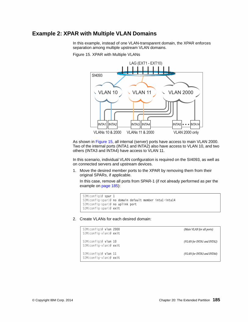
© Copyright IBM Corp. 2014 Chapter 20: The Extended Partition 185
Example 2: XPAR with Multiple VLAN Domains
In this example, instead of one VLAN-transparent domain, the XPAR enforces separation among multiple upstream VLAN domains.
Figure 15. XPAR with Multiple VLANs
As shown in Figure 15, all internal (server) ports have access to main VLAN 2000. Two of the internal ports (INTA1 and INTA2) also have access to VLAN 10, and two others (INTA3 and INTA4) have access to VLAN 11.
In this scenario, individual VLAN configuration is required on the SI4093, as well as on connected servers and upstream devices.
1. Move the desired member ports to the XPAR by removing them from their original SPARs, if applicable.
In this case, remove all ports from SPAR-1 (if not already performed as per the example on page 185):
2. Create VLANs for each desired domain:
SIM(config)# spar 1SIM(config-spar)# no domain default member inta1-inta14SIM(config-spar)# no uplink portSIM(config-spar)# exit
SIM(config)# vlan 2000 (Main VLAN for all ports)SIM(config-vlan)# exit
SIM(config)# vlan 10 (VLAN for INTA1 and INTA2)SIM(config-vlan)# exit
SIM(config)# vlan 11 (VLAN for INTA3 and INTA4)SIM(config-vlan)# exit
...
VLAN 2000VLAN 10 VLAN 11
INTA1 INTA2 INTA3 INTA4 INTA5 INTA14
VLANs 10 & 2000 VLANs 11 & 2000 VLAN 2000 only
LAG (EXT1 - EXT10)
S!4093

186 SI4093 10Gb System Interconnect Module: Application Guide
3. Create the desired uplink entity for each required LAG.
In this case, SPAR-1 was configured by default with EXT1 though EXT10 in a LAG (LACP key 1000, Portchannel ID 65). Because this LAG can be recycled for use with the XPAR, no additional LAG configuration is required. However, for example purposes, the LAG could be manually configured as follows:
4. Assign the desired internal ports and uplink to their VLANs.
5. You can confirm the resulting configuration using the show running-config command.
SIM(config)# portchannel 65 lacp key 1000 suspend-individual
SIM(config)# interface port ext1-ext10SIM(config-if)# lacp key 1000SIM(config-if)# lacp mode activeSIM(config-if)# exit
SIM(config)# interface port inta1-inta2SIM(config-if)# switchport mode trunkSIM(config-if)# switchport trunk native vlan 2000SIM(config-if)# switchport trunk allowed vlan 10SIM(config-if)# exit
SIM(config)# interface port inta3-inta4SIM(config-if)# switchport mode trunkSIM(config-if)# switchport trunk native vlan 2000SIM(config-if)# switchport trunk allowed vlan 11SIM(config-if)# exit
SIM(config)# interface port ext1-ext10SIM(config-if)# switchport mode trunkSIM(config-if)# switchport trunk native vlan 2000SIM(config-if)# switchport trunk allowed vlan add 10,11,2000SIM(config-if)# exit

© Copyright IBM Corp. 2014 Chapter 20: The Extended Partition 187
Example 3: XPAR with Multiple VLAN Domains and FCoE
If the prior example on page 185 required FCoE on VLAN 1002 (typical), the procedure would be modified as follows:
1. Move the desired member ports to the XPAR by removing them from their original SPARs, if applicable:
2. Create VLANs for each desired domain:
3. Create the desired uplink entity for each required LAG if required:
4. Assign the desired internal ports and uplink to their VLANs.
SIM(config)# spar 1SIM(config-spar)# no domain default member inta1-inta14SIM(config-spar)# no uplink portSIM(config-spar)# exit
SIM(config)# vlan 2000 (Main VLAN for all ports)SIM(config-vlan)# exit
SIM(config)# vlan 10 (VLAN for INTA1 and INTA2)SIM(config-vlan)# exit
SIM(config)# vlan 11 (VLAN for INTA3 and INTA4)SIM(config-vlan)# exit
SIM(config)# vlan 1002 (VLAN for FCoE SAN)SIM(config-vlan)# exit
SIM(config)# portchannel 65 lacp key 1000 suspend-individual
SIM(config)# interface port ext1-ext10SIM(config-if)# lacp key 1000SIM(config-if)# lacp mode activeSIM(config-if)# exit
SIM(config)# interface port inta1-inta2SIM(config-if)# switchport mode trunkSIM(config-if)# switchport trunk native vlan 2000SIM(config-if)# switchport trunk allowed vlan 10,1002SIM(config-if)# exit
SIM(config)# interface port inta3-inta4SIM(config-if)# switchport mode trunkSIM(config-if)# switchport trunk native vlan 2000SIM(config-if)# switchport trunk allowed vlan 11,1002SIM(config-if)# exit
SIM(config)# interface port ext1-ext10SIM(config-if)# switchport mode trunkSIM(config-if)# switchport trunk native vlan 2000SIM(config-if)# switchport trunk allowed vlan add 10,11,1002,2000SIM(config-if)# exit

188 SI4093 10Gb System Interconnect Module: Application Guide
5. Ensure that CEE and FIP Snooping are enabled:
6. You can confirm the resulting configuration using the show running-config command.
SIM(config)# cee enableSIM(config)# fcoe fips enable

© Copyright IBM Corp. 2014 189
Chapter 21. VLANs in XPAR
This chapter describes network design and topology considerations for using Virtual Local Area Networks (VLANs) in the XPAR context (see “The Extended Partition” on page 181).
Note: This chapter does not apply to SPARs. For VLAN behavior and configuration within the SPAR context, see “Switch Partitions” on page 85.”
VLANs are commonly used to split up groups of network users into manageable broadcast domains, to create logical segmentation of workgroups, and to enforce security policies among logical segments. The following topics are discussed in this chapter:
• “VLANs and Port VLAN ID Numbers” on page 190
• “VLAN Tagging/Trunk Mode” on page 193
• “VLAN Topologies and Design Considerations” on page 198
• “Private VLANs” on page 200
Note: Basic VLANs can be configured during initial configuration.
VLANs Overview
Setting up virtual LANs (VLANs) is a way to segment networks to increase network flexibility without changing the physical network topology. With network segmentation, each SI4093 port connects to a segment that is a single broadcast domain. When a port is configured to be a member of a VLAN, it is added to a group of ports (workgroup) that belong to one broadcast domain.
Ports are grouped into broadcast domains by assigning them to the same VLAN. Frames received in one VLAN can only be forwarded within that VLAN, and multicast, broadcast, and unknown unicast frames are flooded only to ports in the same VLAN.
The SI4093 automatically supports jumbo frames. This default cannot be manually configured or disabled.
The SI4093 supports jumbo frames with a Maximum Transmission Unit (MTU) of 9,216 bytes. Within each frame, 18 bytes are reserved for the Ethernet header and CRC trailer. The remaining space in the frame (up to 9,198 bytes) comprise the packet, which includes the payload of up to 9,000 bytes and any additional overhead, such as 802.1q or VLAN tags. Jumbo frame support is automatic: it is enabled by default, requires no manual configuration, and cannot be manually disabled.
Note: Jumbo frames are not supported for traffic sent to SI4093 management interfaces.

190 SI4093 10Gb System Interconnect Module: Application Guide
VLANs and Port VLAN ID Numbers
VLAN Numbers
IBM Networking OS supports up to 4095 VLANs per SI4093. By default, VLAN numbers and port assignments are assigned based on initial SPAR configuration (see “Default SPAR Ports” on page 86).
To enforce separation from SPARs, when a port is removed from a SPAR, its VLAN assignment is automatically changed for default XPAR membership:
• Internal (server) ports are assigned default VLAN 1.
• External ports are assigned to VLAN 4091, also known as a black-hole VLAN since egress traffic is not permitted. Members of the black-hole VLAN do not have access to other ports.
VLAN 4095 is reserved for use by the management network, which includes the management ports (MGMT1 and EXTM).
Use the following command to view VLAN information:
Note: The sample screens that appear in this document might differ slightly from the screens displayed by your system. Screen content varies based on the type of chassis unit that you are using and the firmware versions and options that are installed.
SIM(config)# show vlanVLAN Name Status MGT Ports---- -------------------------------- ------ --- -------------------------1 Default VLAN ena dis INTA1-INTA44081 SPAR 1 (DVLAN) ena dis INTA5-INTA14 EXT1-EXT84082 SPAR 2 (DVLAN) ena dis INTB1-INTB14 EXT15-EXT224083 SPAR 3 (DVLAN) ena dis INTC1-INTC14 EXT11-EXT144091 Black-hole VLAN ena dis EXT9-EXT104095 Mgmt VLAN ena ena EXTM MGT1...

© Copyright IBM Corp. 2014 Chapter 21: VLANs in XPAR 191
PVID/Native VLAN Numbers
Each port in the SI4093 has a configurable default VLAN number, known as its PVID or native VLAN. This is the assumed VLAN number for all port traffic not explicitly tagged with its own VLAN number.
By default, the PVID correlates to the default VLAN ID (see “VLAN Numbers” on page 190). The PVID for each port can be configured to any VLAN number between 1 and 4094.
Use the following CLI commands to view PVIDs:
• Port information:
Note: The sample output that appears in this document might differ slightly from that displayed by your system. Output varies based on the type of blade chassis unit that you are using and the firmware versions and options that are installed.
SIM# show interface information (or)SIM# show interface trunkAlias Port Tag RMON Lrn Fld PVID DESCRIPTION VLAN(s) Trk NVLAN ------- ---- --- ---- --- --- ------ -------------- ----------------------------INTA1 1 n d e e 4081 INTA1 1INTA2 2 n d e e 4081 INTA2 1INTA3 3 n d e e 4081 INTA3 1INTA4 4 n d e e 4081 INTA4 1INTA5 5 n d e e 4081 INTA5 4081INTA6 6 n d e e 4081 INTA6 4081INTA7 7 n d e e 4081 INTA7 4081INTA8 8 n d e e 4081 INTA8 4081INTA9 9 n d e e 4081 INTA9 4081INTA10 10 n d e e 4081 INTA10 4081INTA11 11 n d e e 4081 INTA11 4081INTA12 12 n d e e 4081 INTA12 4081INTA13 13 n d e e 4081 INTA13 4081INTA14 14 n d e e 4081 INTA14 4081...EXT9 51 n d e e 4091 EXT9 4091EXT10 52 n d e e 4091 EXT10 4091EXT11 53 n d e e 4083 EXT11 4083EXT12 54 n d e e 4083 EXT12 4083EXT13 55 n d e e 4083 EXT13 4083EXT14 56 n d e e 4083 EXT14 4083EXT15 57 y d e e 4082 EXT15 4082EXT16 58 y d e e 4082 EXT16 4082EXT17 59 y d e e 4082 EXT17 4082EXT18 60 n d e e 4082 EXT18 4082EXT19 61 n d e e 4082 EXT19 4082EXT20 62 n d e e 4082 EXT20 4082EXT21 63 n d e e 4082 EXT21 4082EXT22 64 n d e e 4082 EXT22 4082EXTM 65 n d e e 4095 EXTM 4095MGT1 66 y d e e 4095 MGT1 4095
* = PVID/Native-VLAN is tagged.# = PVID is ingress tagged.Trk = Trunk modeNVLAN = Native-VLAN

192 SI4093 10Gb System Interconnect Module: Application Guide
• Port Configuration:
Each port on the SI4093 can belong to one or more VLANs, and each VLAN can have any number of ports in its membership. Any port that belongs to multiple VLANs, however, must have VLAN tagging enabled (see “VLAN Tagging/Trunk Mode” on page 193).
Black-Hole VLAN
To prevent external ports from inadvertently becoming active in the XPAR context immediately when they are removed from a SPAR, port VLAN assignment for external ports is automatically set to the VLAN 4091 upon removal from the SPAR. VLAN 4091 is known as a system black-hole VLAN since egress traffic is not permitted. Members of the black-hole VLAN do not have access to other ports.
Although VLAN 4091 is the default for use as the system black-hole, any VLAN not reserved for other purposes can be used instead. To set the system black-hole VLAN, use the following Privileged EXEC command in the CLI:
Access Mode Port
SIM(config)# interface port <port number>SIM(config-if)# switchport access vlan <VLAN ID>
For Trunk Mode Port
SIM(config)# interface port <port number>SIM(config-if)# switchport trunk allowed vlan <VLAN ID>
SIM(config)# system black-hole vlan <VLAN ID 2–4095>

© Copyright IBM Corp. 2014 Chapter 21: VLANs in XPAR 193
VLAN Tagging/Trunk Mode
IBM Networking OS software supports 802.1Q VLAN tagging, providing standards-based VLAN support for Ethernet systems.
Tagging places the VLAN identifier in the frame header of a packet, allowing each port to belong to multiple VLANs. When you add a port to multiple VLANs, you also must enable tagging on that port.
Since tagging fundamentally changes the format of frames transmitted on a tagged port, you must carefully plan network designs to prevent tagged frames from being transmitted to devices that do not support 802.1Q VLAN tags, or devices where tagging is not enabled.
Important terms used with the 802.1Q tagging feature are:
• VLAN identifier (VID)—the 12-bit portion of the VLAN tag in the frame header that identifies an explicit VLAN.
• Port VLAN identifier (PVID)—a classification mechanism that associates a port with a specific VLAN. For example, a port with a PVID of 3 (PVID = 3) assigns all untagged frames received on this port to VLAN 3. Any untagged frames received by the SI4093 are classified with the PVID of the receiving port.
• Tagged frame—a frame that carries VLAN tagging information in the header. This VLAN tagging information is a 32-bit field (VLAN tag) in the frame header that identifies the frame as belonging to a specific VLAN. Untagged frames are marked (tagged) with this classification as they leave the SI4093 through a port that is configured as a tagged port.
• Untagged frame— a frame that does not carry any VLAN tagging information in the frame header.
• Untagged member—a port that has been configured as an untagged member of a specific VLAN. When an untagged frame exits the SI4093 through an untagged member port, the frame header remains unchanged. When a tagged frame exits the SI4093 through an untagged member port, the tag is stripped and the tagged frame is changed to an untagged frame.
• Tagged member—a port that has been configured as a tagged member of a specific VLAN. When an untagged frame exits the SI4093 through a tagged member port, the frame header is modified to include the 32-bit tag associated with the PVID. When a tagged frame exits the SI4093 through a tagged member port, the frame header remains unchanged (original VID remains).

194 SI4093 10Gb System Interconnect Module: Application Guide
Figure 16. Default VLAN settings
Note: The port numbers specified in these illustrations may not directly correspond to the physical port configuration of your SI4093 model.
When a VLAN is configured, ports are added as members of the VLAN, and the ports are defined as either tagged or untagged (see Figure 17 through Figure 20).
The default configuration settings for SI4093 XPAR VLANs have all internal ports set as untagged members of VLAN 1 with all ports configured as PVID = 1. In the default configuration example shown in Figure 16, all incoming packets are assigned to VLAN 1 by the default port VLAN identifier (PVID = 1).
Figure 17 through Figure 20 illustrate generic examples of VLAN tagging.
In Figure 17, untagged incoming packets are assigned directly to VLAN 2 (PVID = 2). Port 5 is configured as a tagged member of VLAN 2, and port 7 is configured as an untagged member of VLAN 2.
Note: The port assignments in the following figures are general examples and are not meant to match any specific SI4093.
Figure 17. Port-based VLAN assignment
Port 1
DA
SA
Data
CRC
Incominguntagged
packet
Port 2 Port 3 Port 4 Port 5
VLAN 1
802.1Q Device
By default:
Key
All ports are assigned PVID = 1All external ports are untagged members of VLAN 1All internal server ports are untagged members of VLAN 1
PVID = 1Port 6 ...
DA
SA
Data
CRC
Outgoinguntagged packet
(unchanged)
Port 7
Port 6
DASADataCRC
Port 7 Port 8
Port 1
Port
4
Port
5
Port 2 Port 3
802.1Q Device
PVID = 2
Untagged packet
Untagged memberof VLAN 2
Tagged memberof VLAN 2
Before
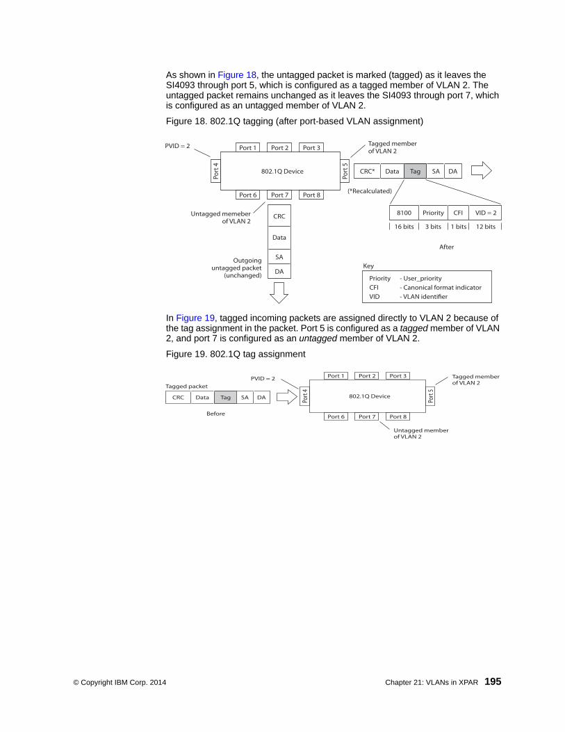
© Copyright IBM Corp. 2014 Chapter 21: VLANs in XPAR 195
As shown in Figure 18, the untagged packet is marked (tagged) as it leaves the SI4093 through port 5, which is configured as a tagged member of VLAN 2. The untagged packet remains unchanged as it leaves the SI4093 through port 7, which is configured as an untagged member of VLAN 2.
Figure 18. 802.1Q tagging (after port-based VLAN assignment)
In Figure 19, tagged incoming packets are assigned directly to VLAN 2 because of the tag assignment in the packet. Port 5 is configured as a tagged member of VLAN 2, and port 7 is configured as an untagged member of VLAN 2.
Figure 19. 802.1Q tag assignment
Port 6 Port 7 Port 8
Port 1
Port
4
Port
5
Port 2 Port 3
802.1Q Device
Key
PriorityCFI VID
- User_priority- Canonical format indicator- VLAN identifier
PVID = 2 Tagged memberof VLAN 2
Untagged memeberof VLAN 2
After
DA
SA
Data
CRC
(*Recalculated)
Outgoinguntagged packet
(unchanged)
DASADataCRC* Tag
VID = 2Priority
16 bits 3 bits 1 bits 12 bits
8100 CFI
Port 6
DASATagDataCRC
Tagged packet
Port 7 Port 8
Port 1
Port
4
Port
5
Port 2 Port 3
802.1Q Device
PVID = 2
Untagged memberof VLAN 2
Tagged memberof VLAN 2
Before

196 SI4093 10Gb System Interconnect Module: Application Guide
As shown in Figure 20, the tagged packet remains unchanged as it leaves the SI4093 through port 5, which is configured as a tagged member of VLAN 2. However, the tagged packet is stripped (untagged) as it leaves the SI4093 through port 7, which is configured as an untagged member of VLAN 2.
Figure 20. 802.1Q tagging (after 802.1Q tag assignment)
Note: Set the configuration to factory default (SIM(config)# boot configuration-block factory) to reset all non-management ports to their original SPAR VLANs.
Ingress VLAN Tagging
Tagging can be enabled on an ingress port. When a packet is received on an ingress port, and if ingress tagging is enabled on the port, a VLAN tag with the port PVID is inserted into the packet as the outer VLAN tag. Depending on the egress port setting (tagged or untagged), the outer tag of the packet is retained or removed when it leaves the egress port.
Ingress VLAN tagging is used to tunnel packets through a public domain without altering the original 802.1Q status.
When ingress tagging is enabled on a port, all packets, whether untagged or tagged, will be tagged again. As shown in Figure 21, when tagging is enabled on the egress port, the outer tag of the packet is retained when it leaves the egress port. If tagging is disabled on the egress port, the outer tag of the packet is removed when it leaves the egress port.
BS45014A
Port 6 Port 7 Port 8
Port 1Po
rt 4
Port
5
Port 2 Port 3
802.1Q Device
Key
PriorityCFI VID
- User_priority- Canonical format indicator- VLAN identi er
of VLAN 2
Untagged memberof VLAN 2
After
DA
SA
Data
CRC* (*Recalculated)
Outgoinguntagged packetchanged(tag removed)
DASADataCRC Tag
VID = 2Priority
16 bits 3 bits 1 bit 12 bits
8100 CFI
Port 6 Port 7 Port 8
Port 1
Port
4
Port
5
Port 2 Port 3
802.1Q Device
Key
PriorityCFI VID
- User_priority- Canonical format indicator- VLAN identi er
PVID = 2 Tagged memberof VLAN 2
Untagged memberof VLAN 2
After
DA
SA
Data
CRC* (*Recalculated)
Outgoinguntagged packetchanged(tag removed)
DASADataCRC Tag
VID = 2Priority
16 bits 3 bits 1 bit 12 bits
8100 CFI
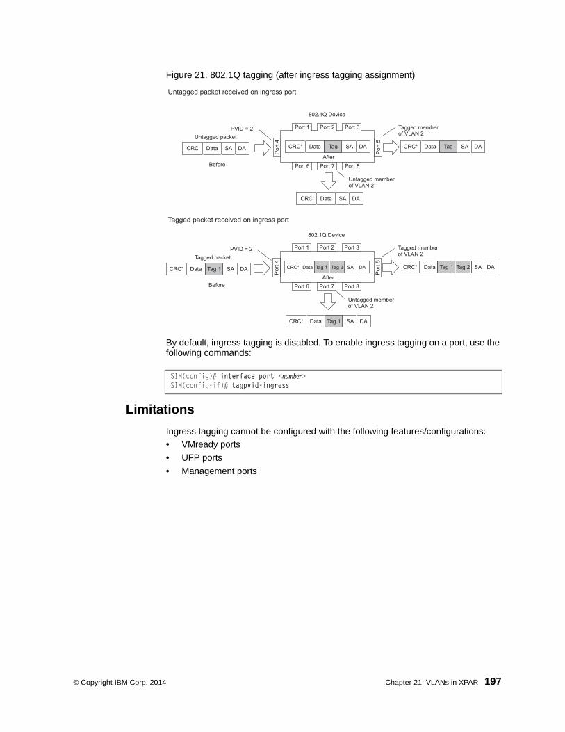
© Copyright IBM Corp. 2014 Chapter 21: VLANs in XPAR 197
Figure 21. 802.1Q tagging (after ingress tagging assignment)
By default, ingress tagging is disabled. To enable ingress tagging on a port, use the following commands:
Limitations
Ingress tagging cannot be configured with the following features/configurations:
• VMready ports
• UFP ports
• Management ports
SIM(config)# interface port <number>SIM(config-if)# tagpvid-ingress
Port 6
DASADataCRC
Port 7 Port 8
Port 1
Por
t 4
Por
t 5
Port 2 Port 3
802.1Q Device
PVID = 2Untagged packet
Untagged memberof VLAN 2
Tagged memberof VLAN 2
Before
DASADataCRC* TagDASADataCRC* Tag
After
DASADataCRC
Port 6 Port 7 Port 8
Port 1
Por
t 4
Por
t 5
Port 2 Port 3
802.1Q Device
PVID = 2Tagged packet
Untagged memberof VLAN 2
Tagged memberof VLAN 2
Before
DASADataCRC* Tag 1DASADataCRC* Tag 1
AfterDASADataCRC* Tag 1 Tag 2 Tag 2
DASADataCRC* Tag 1
Untagged packet received on ingress port
Tagged packet received on ingress port

198 SI4093 10Gb System Interconnect Module: Application Guide
VLAN Topologies and Design Considerations• By default, the IBM Networking OS software is configured so that tagging is dis-
abled on all external ports and on all internal ports.
• By default, the IBM Networking OS software is configured so that all XPAR internal ports are members of VLAN 1.
• By default, the IBM Networking OS software is configured so that the manage-ment port MGMT1 and EXTM are members of the default management VLAN 4095.
VLAN Configuration Rules
VLANs operate according to specific configuration rules. When creating VLANs, consider the following rules that determine how the configured VLAN reacts in any network topology:
• The management VLAN includes ports EXTM and MGT1. Internal ports (INTx) and numbered External ports (EXTx) cannot be members of the management VLAN.
Example: Multiple VLANs with Tagging Adapters
Figure 22. Multiple VLANs with VLAN-Tagged Gigabit Adapters
The features of this VLAN are described in the following table:
VLAN #1, 2, 3VLAN #3Server #1 Server #2
Gigabit/Taggedadapter
Shared Media
PC #1VLAN #2
PC #2VLAN #2
PC #3VLAN #1
PC #4VLAN #3
PC #5VLAN #1 & #2
SI4093
Component Description
SI4093 This SI4093 XPAR is configured for three VLANs that represent three different IP subnets. Two servers and five clients are attached to the SI4093.
Server #1 This server is a member of VLAN 3 and has presence in only one IP subnet. The associated internal SI4093 port is only a member of VLAN 3, so tagging is disabled.

© Copyright IBM Corp. 2014 Chapter 21: VLANs in XPAR 199
Note: VLAN tagging is required only on ports that are connected to other SI4093s or on ports that connect to tag-capable end-stations, such as servers with VLAN-tagging adapters.
Server #2 This high-use server needs to be accessed from all VLANs and IP subnets. The server has a VLAN-tagging adapter installed with VLAN tagging turned on. The adapter is attached to one of the internal SI4093 ports, that is a member of VLANs 1, 2, and 3, and has tagging enabled. Because of the VLAN tagging capabilities of both the adapter and the SI4093, the server is able to communicate on all three IP subnets in this network. Broadcast separation between all three VLANs and subnets, however, is maintained.
PCs #1 and #2
These PCs are attached to a shared media hub that is then connected to the SI4093. They belong to VLAN 2 and are logically in the same IP subnet as Server 2 and PC 5. The associated external SI4093 port has tagging disabled.
PC #3 A member of VLAN 1, this PC can only communicate with Server 2 and PC 5. The associated external SI4093 port has tagging disabled.
PC #4 A member of VLAN 3, this PC can only communicate with Server 1 and Server 2. The associated external SI4093 port has tagging disabled.
PC #5 A member of both VLAN 1 and VLAN 2, this PC has a VLAN-tagging Gigabit Ethernet adapter installed. It can communicate with Server 2 and PC 3 via VLAN 1, and to Server 2, PC 1 and PC 2 via VLAN 2. The associated external SI4093 port is a member of VLAN 1 and VLAN 2, and has tagging enabled.
Component Description

200 SI4093 10Gb System Interconnect Module: Application Guide
Private VLANs
Private VLANs provide Layer 2 isolation between the ports within the same broadcast domain. Private VLANs can control traffic within a VLAN domain, and provide port-based security for host servers.
IBM Networking OS supports Private VLAN configuration as described in RFC 5517.
Use Private VLANs to partition a VLAN domain into sub-domains. Each sub-domain is comprised of one primary VLAN and one secondary VLAN, as follows:
• Primary VLAN—carries unidirectional traffic downstream from promiscuous ports. Each Private VLAN has only one primary VLAN. All ports in the Private VLAN are members of the primary VLAN.
• Secondary VLAN—Secondary VLANs are internal to a private VLAN domain, and are defined as follows:
– Isolated VLAN—carries unidirectional traffic upstream from the host servers toward ports in the primary VLAN and the gateway. Each Private VLAN can contain only one Isolated VLAN.
– Community VLAN—carries upstream traffic from ports in the community VLAN to other ports in the same community, and to ports in the primary VLAN and the gateway. Each Private VLAN can contain multiple community VLANs.
After you define the primary VLAN and one or more secondary VLANs, you map the secondary VLAN(s) to the primary VLAN.
Private VLAN Ports
Private VLAN ports are defined as follows:
• Promiscuous—A promiscuous port is an external port that belongs to the primary VLAN. The promiscuous port can communicate with all the interfaces, including ports in the secondary VLANs (Isolated VLAN and Community VLANs). Each promiscuous port can belong to only one Private VLAN.
• Isolated—An isolated port is a host port that belongs to an isolated VLAN. Each isolated port has complete layer 2 separation from other ports within the same private VLAN (including other isolated ports), except for the promiscuous ports.
– Traffic sent to an isolated port is blocked by the Private VLAN, except the traffic from promiscuous ports.
– Traffic received from an isolated port is forwarded only to promiscuous ports.
• Community—A community port is a host port that belongs to a community VLAN. Community ports can communicate with other ports in the same community VLAN, and with promiscuous ports. These interfaces are isolated at layer 2 from all other interfaces in other communities and from isolated ports within the Private VLAN.

© Copyright IBM Corp. 2014 Chapter 21: VLANs in XPAR 201
Configuration Guidelines
The following guidelines apply when configuring Private VLANs:
• Management VLANs cannot be Private VLANs. Management ports cannot be members of a Private VLAN.
• The default VLAN 1 cannot be a Private VLAN.
• IGMP Snooping must be disabled on Private VLANs.
Configuration Example
Follow this procedure to configure a Private VLAN.
1. Select a VLAN and define the Private VLAN type as primary.
2. Configure a promiscuous port for VLAN 700.
3. Configure two secondary VLANs: isolated VLAN and community VLAN.
4. Map secondary VLANs to primary VLAN.
5. Configure host ports for secondary VLANs.
SIM(config)# vlan 700SIM(config-vlan)# private-vlan primarySIM(config-vlan)# exit
SIM(config)# interface port inta1SIM(config-if)# switchport mode private-vlanSIM(config-if)# switchport private-vlan mapping 700SIM(config-if)# exit
SIM(config)# vlan 701SIM(config-vlan)# private-vlan isolatedSIM(config-vlan)# exitSIM(config)# vlan 702SIM(config-vlan)# private-vlan communitySIM(config-vlan)# exit
SIM(config)# vlan 700SIM(config-vlan)# private-vlan association 701,702SIM(config-vlan)# exit
SIM(config)# interface port inta2SIM(config-if)# switchport mode private-vlanSIM(config-if)# switchport private-vlan host-association 700 701SIM(config-if)# exit
SIM(config)# interface port inta3SIM(config-if)# switchport mode private-vlanSIM(config-if)# switchport private-vlan host-association 700 702SIM(config-if)# exit

202 SI4093 10Gb System Interconnect Module: Application Guide
6. Verify the configuration.
SIM(config)# show vlan private-vlan
Primary Secondary Type Ports------- --------- --------------- ---------------------------------700 701 isolated INTA1-INTA2700 702 community 1NTA1 INTA3

© Copyright IBM Corp. 2014 Chapter 22: Unified Fabric Port in XPAR 203
Chapter 22. Unified Fabric Port in XPAR
Note: This feature is supported in the XPAR context only (see “The Extended Partition” on page 181). This chapter does not apply to SPARs.
Unified Fabric Port (UFP) is a cost-effective way to allocate, share and dynamically control network bandwidth between a server and the SI4093. UFP lets you create multiple virtual connections. The UFP protocol is a link-level protocol that runs a separate instance for each physical communication link established between a server NIC and SI4093 port. Virtualizing the ports allows you to separate or aggregate port traffic by applying the network policies defined on the SI4093. Virtualization lessens bottlenecks and provides higher bandwidth while consolidating equipment use.
UFP extends the SI4093 fabric to control the NICs. The server operating system (OS) or hypervisor recognizes each subdivided link (channel) as an independent physical NIC. Each channel has a unique identity and profile that defines its properties and functionality. The server communicates with the SI4093 over the channel as defined in the channel profile. The channels share the high-speed physical link bandwidth.
For each channel, the vNIC on the server side communicates with virtual port on the SI4093. Any 10 Gbps internal server port can be configured as an UFP port.
Figure 23. UFP vPorts
The UFP protocol has the following operation categories:
• Channel Initialization: The server NIC and the SI4093 port negotiate the number of channels and establish channel identifiers. Each UFP channel has a data component and a control component. The two components have the same UFP channel ID.
• Channel Control: For an established channel, the SI4093 can modify channel properties by sending a control message on the UFP channel. While the channel ID is the same for the control and data components, the destination MAC address of the control message frame is a well-known address.
• Discovery Capability: UFP can discover other ports that are UFP enabled. Once you enable UFP, you can check the information statistics for established channels.
NIC
OS or Hypervisor
Blade Server
IBMSI4093
VNICVNIC
VNICVNIC
PhysicalNIC Port
InternalSwitch Port vPort
vPort
vPort
vPort

204 SI4093 10Gb System Interconnect Module: Application Guide
UFP Limitations
The following limitations apply when configuring UFP:
• FCoE must be configured only on vPort 2 of the physical NIC.
• UFP port in FCoE mode cannot operate with FIP auto-VLAN feature.
• VLANs that have member vPorts configured in trunk-, access-, or auto-modes cannot have member vPorts configured in tunnel mode or FCoE.
• vPorts on a physical port must be members of separate VLANs.
• VLANs 4002-4005 are reserved for outer tagging.
• VLAN translation is not applied on egress ports that have UFP enabled but no vPorts configured in trunk-, access-, or auto-modes.
• UFP bandwidth is guaranteed lossless only for unicast traffic.
• VMready is supported only on a vPort which is configure in auto-VLAN mode. When a vPort is in auto-VLAN mode, it can support up to 32 VMGroups.
• EVB is supported only on a vPort which is configured in auto-VLAN mode.
• VMready and EVB cannot be configured on the same physical port.
• UFP vPorts can support up to 256 VLANs.
• When CEE is turned on, FCoE vPort must be used for lossless priority traffic. For loss-tolerant priority traffic, a non-FCoE UFP vPort must be used. The lossless property of FCoE vPort is not guaranteed, if lossless and loss-tolerant traffic are combined.
• When the vPort is enabled and the channel link state is up, the system does not support changing vPort VLAN type from private/non-private to non-private/private.
• A maximum of four vPorts can be configured for each physical SI4093 port.
• VMReady Local Group configuration is not supported by UFP.

© Copyright IBM Corp. 2014 Chapter 22: Unified Fabric Port in XPAR 205
Virtual Ports Modes
A single physical SI4093 port is configured with virtual ports (vPorts). Each UFP channel connects the server NIC with vPort on the SI4093. Properties that are defined for a vPort, such as native VLAN and bandwidth, are applied to the traffic that belongs to the vPort.
Note: A maximum of four vPorts can be configured for each physical SI4093 port.
vPort-S-Tag Mapping
A vPort can also be identified with an S-tag (service tag or outer tag). When a vPort is initialized, the SI4093 communicates the UFP channel ID of the vPort to the server NIC. When the server NIC or SI4093 transmits frames, they add this S-tag to indicate the vPort or vNIC to which the packet is being transmitted. No VLAN mapping is required. Such packets can be single tagged or double tagged (with S-tag).
vPort-VLAN Mapping
In local domain data path type, the SI4093 and server identify the vPort and vNIC by the port and VLAN tag in the incoming and outgoing packets. Because no two vPorts carry traffic for the same VLAN, the port-and-VLAN combination must be uniquely mapped to a vPort.
UFP vPort Mode
The UFP mode is configured based on the type of domain (single VLAN or multiple VLANs) where the vPort is connected.
• Use local domain data path types for trunk or access mode.
• Use pass-through domain data path types for tunnel mode. In tunnel mode, a vPort can belong to only one VLAN.
Use the following command to configure UFP vPort mode:
SIM(config)# ufp port <num> vport <num>SIM(config_ufp_vport)# network mode {access|trunk|auto|tunnel|fcoe}
Default mode is ‘tunnel’

206 SI4093 10Gb System Interconnect Module: Application Guide
Tunnel Mode
In tunnel mode, a vPort can belong to only one VLAN. An outer tag with the vPort’s VLAN ID is inserted in packets that egress the vPort. The inner VLAN tag remains unchanged. The SI4093 processes packets based on the outer tag. When all the ports or vPorts that belong to a particular VLAN are placed in tunnel mode, they belong to one pass-through domain.
Use tunnel mode to send all VM data traffic to an upstream switch, for Layer 2 or Layer 3 processing, in one domain. In such cases, the UFP port or vPort must be in tunnel mode and the upstream switch port must be in 802.1Q trunk mode.
Note: Two vPorts on a physical port cannot be members of the same VLAN.
Figure 24. Packet pass-through in Tunnel Mode
802.1Q Trunk Mode
In trunk mode, a vPort can carry packets that have inner tags that belong to up to 256 VLANs. A maximum of 2048 VLANs for all UFP vPorts can be configured on the SI4093. Each VLAN in the inner tag requires a VLAN translation entry.
Note: Two vPorts operating in trunk mode on the same physical port cannot carry the same set of VLANs in the inner tag.
Figure 25. Packet passing through in Trunk Mode
OutboundPacket
InboundPacket
RegularVLAN ID NIC attaches UFP
Channel VLAN ID
SI4093 adds outerChannel VLAN ID
Outer tag sets vNIC;NIC strips outer tag
Path uses outer tag;Ignores regular VLAN
Path uses outer tag;Ignores regular VLAN
SI4093 removesouter tag
Server SI4093 Ports withoutvNICs
vNICsOS/Hypervisor NIC
vPorts
OutboundPacket
RegularVLAN IDs NIC attaches UFP
Channel VLAN IDSI4093 removes
outer tag
Server SI4093 Ports withoutvNICs
vNICOS/Hypervisor NIC
vPort
VLAN Translation
VLAN Classification

© Copyright IBM Corp. 2014 Chapter 22: Unified Fabric Port in XPAR 207
Access Mode
In access mode, a vPort carries packets with inner tags that belong to one VLAN. The vPort is associated with the VLAN defined by the command:
Note: VLANs 4002-4005 are reserved for outer tagging.
FCoE Mode
FCoE traffic is carried by a vPort. The server-side endpoint of this virtual port will be represented through a FC vHBA. Setting a virtual port in FCoE mode will enable Priority-based Flow Control (PFC) on the physical port.
A vPort configured in FCoE mode can only be attached to a Fibre Channel (FC) VLAN. Only vPort 2 on a physical port can be configured in FCoE mode. A vPort in FCoE mode operates as a local domain data path type with packets being single tagged.
Auto-VLAN Mode
When a vPort is configured in auto-VLAN mode, the vPort participates in VM discovery using VMready or 802.1Qbg. VLANs are dynamically provisioned based on VMready discovery or 802.1Qbg VM association.
When a vPort operates in auto-VLAN mode, it supports 32 VM groups. In the case of 802.1Qbg, when a vPort operates in auto-VLAN mode, the maximum number of VLANs in the inner tag are 256. The vPort cannot be configured in Virtual Ethernet Port Aggregator (VEPA) mode.
SIM(config_ufp_vport)# network default-vlan <2-4094>
208 SI4093 10Gb System Interconnect Module: Application Guide
UFP Bandwidth Provisioning
UFP provides one mode of bandwidth provisioning for vPort: Strict Bandwidth Provisioning Mode.
UFP Strict Bandwidth Provisioning Mode
Strict bandwidth provisioning mode configures the SI4093 and NIC apply bidirectional bandwidth control on the vPort as per the defined configuration. By default, a bandwidth of 2.5 Gbps per vPort is guaranteed. If other vPorts are idle, the bandwidth of a vPort can be up to 10 Gbps. A minimum bandwidth of 1 Gbps is provisioned, which can be raised by 100 Mbps increments. The sum of the minimum bandwidth guaranteed for all vPorts together cannot exceed the capacity of the physical link. A vPort can also be configured with a maximum bandwidth.
This mode works with the port scheduler to avoid unintended packet drops due to policing through EFP metering block. If flow control is enabled, the SI4093 provides a no-drop packet forwarding behavior, which improves end-to-end TCP-throughput performance.
Note: If a vPort is configured with low upper limit, it might lead to head-of-line congestion on the egress port.
By default, uplink ports have a separate traffic class for storage traffic with guaranteed bandwidth. The rest of the bandwidth is shared equally among other traffic.
Use the following command to configure strict bandwidth provisioning:
SIM(config_ufp_vport)# qos bandwidth {max|min} <10-100>
min - Set minimum guaranteed bandwidthmax - Set maximum allowed bandwidth

© Copyright IBM Corp. 2014 Chapter 22: Unified Fabric Port in XPAR 209
Using UFP with Other SI4093 Features
UFP works with other SI4093 features, as described with limitations and details.
Layer 2 Failover
UFP failover can be configured with auto-monitoring or manual monitoring. In auto-monitoring, a vPort is automatically associated with a Failover trigger if it has any VLAN in common with the monitor ports.
Layer 2 failover is not supported on UFP ports in auto mode.
Increased VLAN Limits
Configured with UFP and VLANs, a vPort can support maximum 256 VLANs. A UFP port supports 256 VLANs.
VMReady
Configuring with UFP and VMReady, the SI4093 can support up to 32 VMGroups with UFP vPorts in auto-mode.
VMReady is supported only on a vPort which is configured in auto-VLAN mode.
Edge Virtual Bridging
Configured with 802.1Qbg Edge Virtual Bridging (EVB), UFP supports up to 256 VLANs on a vPort.
EVB is supported only on a vPort which is configured in auto-VLAN mode.

210 SI4093 10Gb System Interconnect Module: Application Guide
Updating from IBM Networking OS 7.7 or Prior
Beginning with N/OS 7.8, physical ports that have UFP enabled cannot be members of a failover trigger; only the vPorts can be members of a failover trigger. In a previous configuration (N/OS 7.7 or prior), if you had UFP-enabled ports as members of a failover trigger, the trigger will not work as expected after you update the SI4093 software version to N/OS 7.8 or later.You may also experience other issues, such as not being able to shutdown or restart the UFP-enabled ports.
To overcome this issue, do the following:
1. Disable the trigger (SI4093(config)# no failover trigger x enable).
2. Reconfigure the trigger using the appropriate commands. For the UFP-enabled port, add the vPorts as members of the failover trigger (SI4093(config)# failover trigger x mmon control vmember <vPorts list separated by comma>). See Step 2 on page 216 for an example.
3. Enable the trigger (SI4093(config)# failover trigger x enable).
OR
1. Remove the UFP-enabled port from the trigger (SI4093(config)# no failover trigger x mmon control member <UFP-enabled port number>).
2. Add the vPorts as members of the failover trigger (SI4093(config)# failover trigger x mmon control vmember <vPorts list separated by comma>).

© Copyright IBM Corp. 2014 Chapter 22: Unified Fabric Port in XPAR 211
UFP Configuration Examples
Following is an example configuration of UFP vPorts in access mode.
Example 1: Access Mode1. Turn on UFP.
2. Configure internal port as UFP.
3. Configure virtual port.
4. Configure vPort access mode.
5. Configure vPort default VLAN.
6. Ensure tagging is disabled on vPort.
7. Specify QoS parameters for the vPort.
8. Configure PVID/Native VLAN for external port 1.
SI4093(config)# ufp enable
SI4093(config)# ufp port INTA1 enable
Warning: "Tagging/Trunk-mode" is enabled on UFP port INTA1
SI4093(config)# ufp port INTA1 vport 1
SI4093(config_ufp_vport)# network mode access
SI4093(config_ufp_vport)# network default-vlan 100
SI4093(config_ufp_vport)# no network default-tag
SI4093(config_ufp_vport)# qos bandwidth min 25 (in percentage)SI4093(config_ufp_vport)# qos bandwidth max 100 (in percentage)SI4093(config_ufp_vport)# enableSI4093(config_ufp_vport)# exit
SI4093(config)# interface port EXT1SI4093(config-if)# switchport mode accessSI4093(config-if)# switchport access vlan 100

212 SI4093 10Gb System Interconnect Module: Application Guide
Example 2: Trunk Mode
Following is an example configuration of UFP vPorts in trunk mode.
1. Turn on UFP.
2. Configure internal port 1 as UFP.
3. Configure virtual port.
4. Configure vPort trunk mode.
5. Configure vPort default VLAN.
6. Specify QoS parameters for the vPort.
7. Configure internal port 2 as UFP.
8. Configure virtual port.
9. Configure vPort trunk mode.
10. Configure vPort default VLAN.
SIM(config)# ufp enable
SI4093(config)# ufp port INTA1 enable
Warning: "Tagging/Trunk-mode" is enabled on UFP port INTA1
SI4093(config)# ufp port INTA1 vport 1
SI4093(config_ufp_vport)# network mode trunk
SI4093(config_ufp_vport)# network default-vlan 100
SI4093(config_ufp_vport)# qos bandwidth min 25 (in percentage)SI4093(config_ufp_vport)# qos bandwidth max 100 (in percentage)SI4093(config_ufp_vport)# enableSI4093(config_ufp_vport)# exit
SI4093(config)# ufp port INTA2 enable
Warning: "Tagging/Trunk-mode" is enabled on UFP port INTA2
SI4093(config)# ufp port INTA2 vport 3
SI4093(config_ufp_vport)# network mode trunk
SI4093(config_ufp_vport)# network default-vlan 100

© Copyright IBM Corp. 2014 Chapter 22: Unified Fabric Port in XPAR 213
11. Ensure tagging is disabled on vPort.
12. Specify QoS parameters for the vPort.
13. Enable tagging/trunk mode on external port 1.
14. Configure VLAN 200 parameters.
15. Configure VLAN 300 parameters.
Example 3: Auto-VLAN Mode1. Turn on UFP.
2. Configure internal port 1 as UFP.
3. Configure virtual port.
4. Configure vPort default VLAN.
SI4093(config_ufp_vport)# no network default-tag
SI4093(config_ufp_vport)# qos bandwidth min 25 (in percentage)SI4093(config_ufp_vport)# qos bandwidth max 100 (in percentage)SI4093(config_ufp_vport)# enableSI4093(config_ufp_vport)# exit
SI4093(config)# interface port EXT1SI4093(config-if)# switchport mode trunkSI4093(config-if)# switchport trunk native vlan 100SI4093(config-if)# switchport trunk allowed vlan add 200,300SI4093(config-if)# exit
SI4093(config)# vlan 200SI4093(config-vlan)# vmember INTA1.3SI4093(config-vlan)# vmember INTA2.3SI4093(config-vlan)# exit
SI4093(config)# vlan 300SI4093(config-vlan)# vmember INTA1.3SI4093(config-vlan)# vmember INTA2.3SI4093(config-vlan)# exit
SIM(config)# ufp enable
SI4093(config)# ufp port INTA1 enable
Warning: "Tagging/Trunk-mode" is enabled on UFP port INTA1
SI4093(config)# ufp port INTA1 vport 1
SI4093(config_ufp_vport)# network default-vlan 100

214 SI4093 10Gb System Interconnect Module: Application Guide
5. Configure vPort auto mode.
Note: VLAN is dynamically added by 802.1Qbg.
6. Specify QoS parameters for the vPort.
Example 4: Tunnel Mode
Following is an example configuration of UFP vPorts in tunnel mode.
1. Turn on UFP.
2. Configure internal port as UFP.
3. Configure virtual port.
4. Configure vPort tunnel mode.
5. Configure vPort default VLAN.
6. Ensure tagging is disabled on vPort.
7. Specify QoS parameters for the vPort.
SI4093(config_ufp_vport)# network mode auto
SI4093(config_ufp_vport)# qos bandwidth min 25 (in percentage)SI4093(config_ufp_vport)# qos bandwidth max 100 (in percentage)SI4093(config_ufp_vport)# enableSI4093(config_ufp_vport)# exit
SIM(config)# ufp enable
SI4093(config)# ufp port INTA1 enable
Warning: "Tagging/Trunk-mode" is enabled on UFP port INTA1
SI4093(config)# ufp port INTA1 vport 1
SI4093(config_ufp_vport)# network mode tunnel
SI4093(config_ufp_vport)# network default-vlan 4000
SI4093(config_ufp_vport)# no network default-tag
SI4093(config_ufp_vport)# qos bandwidth min 25 (in percentage)SI4093(config_ufp_vport)# qos bandwidth max 100 (in percentage)SI4093(config_ufp_vport)# enableSI4093(config_ufp_vport)# exit
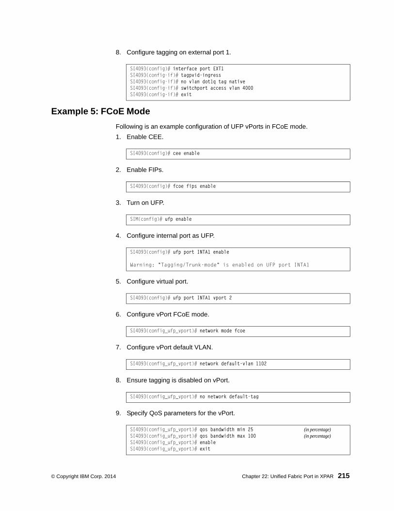
© Copyright IBM Corp. 2014 Chapter 22: Unified Fabric Port in XPAR 215
8. Configure tagging on external port 1.
Example 5: FCoE Mode
Following is an example configuration of UFP vPorts in FCoE mode.
1. Enable CEE.
2. Enable FIPs.
3. Turn on UFP.
4. Configure internal port as UFP.
5. Configure virtual port.
6. Configure vPort FCoE mode.
7. Configure vPort default VLAN.
8. Ensure tagging is disabled on vPort.
9. Specify QoS parameters for the vPort.
SI4093(config)# interface port EXT1SI4093(config-if)# tagpvid-ingressSI4093(config-if)# no vlan dot1q tag native SI4093(config-if)# switchport access vlan 4000SI4093(config-if)# exit
SI4093(config)# cee enable
SI4093(config)# fcoe fips enable
SIM(config)# ufp enable
SI4093(config)# ufp port INTA1 enable
Warning: "Tagging/Trunk-mode" is enabled on UFP port INTA1
SI4093(config)# ufp port INTA1 vport 2
SI4093(config_ufp_vport)# network mode fcoe
SI4093(config_ufp_vport)# network default-vlan 1102
SI4093(config_ufp_vport)# no network default-tag
SI4093(config_ufp_vport)# qos bandwidth min 25 (in percentage)SI4093(config_ufp_vport)# qos bandwidth max 100 (in percentage)SI4093(config_ufp_vport)# enableSI4093(config_ufp_vport)# exit

216 SI4093 10Gb System Interconnect Module: Application Guide
10. Enable tagging/trunk mode on external port.
Example 6: Layer 2 Failover Configuration
While configuring a failover trigger, you cannot use the member command for a physical port that has vPorts configured. Instead, you must use the vmember command to add the vPorts as members of a failover trigger. The following example includes the commands to configure a failover trigger using a physical port INTA8 (UFP not enabled) and vPorts INTA9.1, INTA9.2, INTA9.3, and INTA9.4 configured on UFP-enabled physical port INTA9.
See “Example 1: Access Mode” on page 211 for steps to configure a vPort in access mode. Follow the steps below for configuring the failover trigger:
1. Enable failover globally:
2. Configure trigger 1 and add monitor and control ports:
Note: If you try to add a physical port (that has vPorts configured) as a member of a trigger, you may see the following error message when you enable the trigger:
SI4093(config)#failover trigger 1 ena
Failover Error: trigger 1 physical port INTA9 has virtual ports.
3. Enable failover trigger:
SI4093(config)# interface port EXT1SI4093(config-if)# switchport mode trunkSI4093(config-if)# switchport trunk native vlan 1SI4093(config-if)# exit
SI4093(config)# failover enable
SI4093(config)# failover trigger 1 mmon monitor member EXT1SI4093(config)# failover trigger 1 mmon control member INTA8SI4093(config)# failover trigger 1 mmon control vmember
INTA9.1,INTA9.2,INTA9.3,INTA9.4
SI4093(config)# failover trigger 1 enable

© Copyright IBM Corp. 2014 217
Chapter 23. VMready in XPAR
Note: This feature is supported in the XPAR context only (see “The Extended Partition” on page 181). This chapter does not apply to SPARs.
Virtualization is used to allocate server resources based on logical needs, rather than on strict physical structure. With appropriate hardware and software support, servers can be virtualized to host multiple instances of operating systems, known as virtual machines (VMs). Each VM has its own presence on the network and runs its own service applications.
Software known as a hypervisor manages the various virtual entities (VEs) that reside on the host server: VMs, virtual switches, and so on. Depending on the virtualization solution, a virtualization management server may be used to configure and manage multiple hypervisors across the network. With some solutions, VMs can even migrate between host hypervisors, moving to different physical hosts while maintaining their virtual identity and services.
The IBM Networking OS 7.8 VMready feature supports up to4096 VEs in a virtualized data center environment. The SI4093 automatically discovers the VEs attached to SI4093 ports, and distinguishes between regular VMs, Service Console Interfaces, and Kernel/Management Interfaces in a VMware® environment.
VEs may be placed into VM groups on the SI4093 to define communication boundaries: VEs in the same VM group may communicate with each other, while VEs in different groups may not. VM groups also allow for configuring group-level settings such as virtualization policies and ACLs.
The administrator can also pre-provision VEs by adding their MAC addresses (or their IPv4 address or VM name in a VMware environment) to a VM group. When a VE with a pre-provisioned MAC address becomes connected to the SI4093, the SI4093 will automatically apply the appropriate group membership configuration.
The SI4093 with VMready also detects the migration of VEs across different hypervisors. As VEs move, the SI4093 NMotion™ feature automatically moves the appropriate network configuration as well. NMotion gives the SI4093 the ability to maintain assigned group membership and associated policies, even when a VE moves to a different port on the SI4093.
VMready also works with VMware Virtual Center (vCenter) management software. Connecting with a vCenter allows the SI4093 to collect information about more distant VEs, synchronize SI4093 and VE configuration, and extend migration properties.

218 SI4093 10Gb System Interconnect Module: Application Guide
VE Capacity
When VMready is enabled, the SI4093 will automatically discover VEs that reside in hypervisors directly connected on the SI4093 ports. IBM Networking OS 7.8 supports up to 4096 VEs. Once this limit is reached, the SI4093 will reject additional VEs.
Note: In rare situations, the SI4093 may reject new VEs prior to reaching the supported limit. This can occur when the internal hash corresponding to the new VE is already in use. If this occurs, change the MAC address of the VE and retry the operation. The MAC address can usually be changed from the virtualization management server console (such as the VMware Virtual Center).
VM Group Types
VEs, as well as internal ports, external ports, static trunks and LACP trunks, can be placed into VM groups on the SI4093 to define virtual communication boundaries. Elements in a given VM group are permitted to communicate with each other, while those in different groups are not. The elements within a VM group automatically share certain group-level settings.
IBM Networking OS 7.8 supports up to 4096 VM groups. There are two different types:
• Local VM groups are maintained locally on the SI4093. Their configuration is not synchronized with hypervisors.
• Distributed VM groups are automatically synchronized with a virtualization man-agement server (see “Assigning a vCenter” on page 227).
Each VM group type is covered in detail in the following sections.
Local VM Groups
The configuration for local VM groups is maintained on the SI4093 (locally) and is not directly synchronized with hypervisors. Local VM groups may include only local elements: local SI4093 ports and trunks, and only those VEs connected to one of the SI4093 ports or pre-provisioned on the SI4093.
Local VM groups support limited VE migration: as VMs and other VEs move to different hypervisors connected to different ports on the SI4093, the configuration of their group identity and features moves with them. However, VE migration to and from more distant hypervisors (those not connected to the SI4093, may require manual configuration when using local VM groups).

© Copyright IBM Corp. 2014 Chapter 23: VMready in XPAR 219
Configuring a Local VM Group
Local VM groups are configured in the VM Group command path:
Use the following ISCLI configuration commands to assign group properties and membership :
The following rules apply to the local VM group configuration commands:
• cpu: Enable sending unregistered IPMC to CPU.
• flood: Enable flooding unregistered IPMC.
• key: Add LACP trunks to the group.
• optflood: Enable optimized flooding to allow sending unregistered IPMC to the Mrouter ports without having any packet loss during the learning period; This option is disabled by default; When optflood is enabled, the flood and cpu settings are ignored.
• port: Add SI4093 ports to the group.
• portchannel: Add static port trunks to the group.
• profile: The profile options are not applicable to local VM groups. Only distributed VM groups may use VM profiles (see “VM Profiles” on page 220).
• tag: Enable VLAN tagging for the VM group. If the VM group contains ports which also exist in other VM groups, enable tagging in both VM groups.
• validate: Set validate mode for the group.
• vlan: Each VM group must have a unique VLAN number. This is required for local VM groups. If one is not explicitly configured, the SI4093 will automatically assign the next unconfigured VLAN when a VE or port is added to the VM group.
• vmap: Each VM group may optionally be assigned a VLAN-based ACL (see “VLAN Maps” on page 230).
• vm: Add VMs. VMs and other VEs are primarily specified by MAC address. They can also be specified by UUID or by the index number as shown in various VMready information output (see “VMready Information Displays” on page 232).
• vport: Add a virtual port.
Add a virtual port to the group.
SIM(config)# virt vmgroup <VM group number>
cpu (Enable sending unregistered IPMC to CPU)
flood (Enable flooding unregistered IPMC)
key <LACP trunk key> (Add LACP trunk to group)optflood (Enable optimized flooding)
port <port alias or number> (Add port member to group)
portchannel <trunk group number> (Add static trunk to group)
profile <profile name> (Not used for local groups)
tag (Set VLAN tagging on ports)
validate <advanced|basic> (Validate mode for the group)
vlan <VLAN number> (Specify the group VLAN)
vm <MAC>|<index>|<UUID>|<IPv4 address>|<name> (Add VM member to group)
vmap <VMAP number> [intports|extports] (Specify VMAP number)
vport <Virtual port> (Add a virtual port to the group)

220 SI4093 10Gb System Interconnect Module: Application Guide
Distributed VM GroupsDistributed VM groups allow configuration profiles to be synchronized between the SI4093 and associated hypervisors and VEs. This allows VE configuration to be centralized, and provides for more reliable VE migration across hypervisors.
Using distributed VM groups requires a virtualization management server. The management server acts as a central point of access to configure and maintain multiple hypervisors and their VEs (VMs, virtual switches, and so on).
The SI4093 must connect to a virtualization management server before distributed VM groups can be used. The SI4093 uses this connection to collect configuration information about associated VEs, and can also automatically push configuration profiles to the virtualization management server, which in turn configures the hypervisors and VEs. See “Virtualization Management Servers” on page 227 for more information.
VM Profiles
VM profiles are required for configuring distributed VM groups. They are not used with local VM groups. A VM profile defines the VLAN and virtual switch bandwidth shaping characteristics for the distributed VM group. The SI4093 distributes these settings to the virtualization management server, which in turn distributes them to the appropriate hypervisors for VE members associated with the group.
Creating VM profiles is a two part process. First, the VM profile is created as shown in the following command on the SI4093:
Next, the profile must be edited and configured using the following configuration commands:
For virtual switch bandwidth shaping parameters, average and peak bandwidth are specified in kilobits per second (a value of 1000 represents 1 Mbps). Burst size is specified in kilobytes (a value of 1000 represents 1 MB).
Note: The bandwidth shaping parameters in the VM profile are used by the hypervisor virtual switch software. To set bandwidth policies for individual VEs, see “VM Policy Bandwidth Control” on page 231.
Once configured, the VM profile may be assigned to a distributed VM group as shown in the following section.
SIM(config)# virt vmprofile <profile name>
SIM(config)# virt vmprofile edit <profile name> ?eshaping <average bandwidth> <burst size> <peak>shaping <average bandwidth> <burst size> <peak>vlan <VLAN number>

© Copyright IBM Corp. 2014 Chapter 23: VMready in XPAR 221
Initializing a Distributed VM Group
Note: A VM profile is required before a distributed VM group may be configured. See “VM Profiles” on page 220 for details.
Once a VM profile is available, a distributed VM group may be initialized using the following configuration command:
Only one VM profile can be assigned to a given distributed VM group. To change the VM profile, the old one must first be removed.
Note: The VM profile can be added only to an empty VM group (one that has no VLAN, VMs, or port members). Any VM group number currently configured for a local VM group (see “Local VM Groups” on page 218) cannot be converted and must be deleted before it can be used for a distributed VM group.
Assigning Members
VMs, ports, and trunks may be added to the distributed VM group only after the VM profile is assigned. Group members are added, pre-provisioned, or removed from distributed VM groups in the same manner as with local VM groups (“Local VM Groups” on page 218), with the following exceptions:
• VMs: VMs and other VEs are not required to be local. Any VE known by the virtualization management server can be part of a distributed VM group.
• The VM group vlan option (see page 219) cannot be used with distributed VM groups. For distributed VM groups, the VLAN is assigned in the VM profile.
SIM(config)# virt vmgroup <VM group number> profile <VM profile name>
SIM(config)# no virt vmgroup <VM group number> profile

222 SI4093 10Gb System Interconnect Module: Application Guide
Synchronizing the Configuration
When the configuration for a distributed VM group is modified, the SI4093 updates the assigned virtualization management server. The management server then distributes changes to the appropriate hypervisors.
For VM membership changes, hypervisors modify their internal virtual switch port groups, adding or removing internal port memberships to enforce the boundaries defined by the distributed VM groups. Virtual switch port groups created in this fashion can be identified in the virtual management server by the name of the VM profile, formatted as follows:
IBM_<VM profile name>
(or)
IBM_<VM profile name>_<index number> (for vDS profiles)
Using the VM Group command path (SIM(config)# virt vmgroup <x> vm) to add a server host interface to a distributed VM group does not create a new port group on the virtual switch or move the host. Instead, because the host interface already has its own virtual switch port group on the hypervisor, the VM profile settings are applied to its existing port group.
Note: When applying the distributed VM group configuration, the virtualization management server and associated hypervisors must take appropriate actions. If a hypervisor is unable to make requested changes, an error message will be displayed on the SI4093. Be sure to evaluate all error message and take the appropriate actions to be sure the expected changes are properly applied.
Removing Member VEs
Removing a VE from a distributed VM group on the SI4093 will have the following effects on the hypervisor:
• The VE will be moved to the IBM_Default (to the IBM_Default_<index number> in case of vDS) port group in VLAN 0 (zero).
• Traffic shaping will be disabled for the VE.
• All other properties will be reset to default values inherited from the virtual switch.

© Copyright IBM Corp. 2014 Chapter 23: VMready in XPAR 223
VMcheck
The SI4093 primarily identifies virtual machines by their MAC addresses. An untrusted server or a VM could identify itself by a trusted MAC address leading to MAC spoofing attacks. Sometimes, MAC addresses get transferred to another VM, or they get duplicated.
The VMcheck solution addresses these security concerns by validating the MAC addresses assigned to VMs. The SI4093 periodically sends hello messages on server ports. These messages include the SI4093 identifier and port number. The hypervisor listens to these messages on physical NICs and stores the information, which can be retrieved using the VMware Infrastructure Application Programming Interface (VI API). This information is used to validate VM MAC addresses. Two modes of validation are available: Basic and Advanced.
Use the following command to select the validation mode or to disable validation:
Basic Validation
This mode provides port-based validation by identifying the port used by a hypervisor. It is suitable for environments in which MAC reassignment or duplication cannot occur.
The SI4093, using the hello message information, identifies a hypervisor port. If the hypervisor port is found in the hello message information, it is deemed to be a trusted port. Basic validation should be enabled when:
• A VM is added to a VM group, and the MAC address of the VM interface is in the Layer 2 table of the SI4093.
• A VM interface that belongs to a VM group experiences a “source miss” i.e. is not able to learn new MAC address.
• A trusted port goes down. Port validation must be performed to ensure that the port does not get connected to an untrusted source when it comes back up.
Use the following command to set the action to be performed if the SI4093 is unable to validate the VM MAC address:
SIM(config)# [no] virt vmgroup <VM group number> validate {basic|advanced}
SIM(config)# virt vmcheck action basic {log|link}
log - generates a loglink - disables the port

224 SI4093 10Gb System Interconnect Module: Application Guide
Advanced Validation
This mode provides VM-based validation by mapping a SI4093 port to a VM MAC address. It is suitable for environments in which spoofing, MAC reassignment, or MAC duplication is possible.
When the SI4093 receives frames from a VM, it first validates the VM interface based on the VM MAC address, VM Universally Unique Identifier (UUID), SI4093 port, and SI4093 ID available in the hello message information. Only if all the four parameters are matched, the VM MAC address is considered valid.
In advanced validation mode, if the VM MAC address validation fails, an ACL can be created to drop the traffic received from the VM MAC address on the SI4093 port. Use the following command to specify the number of ACLs to be used for dropping traffic:
Use the following command to set the action to be performed if the SI4093 is unable to validate the VM MAC address:
Following are the other VMcheck commands:
SIM(config)# virt vmcheck acls max <1-256>
SIM(config)# virt vmcheck action advanced {log|link|acl}
Table 24. VMcheck Commands
Command Description
SIM(config)# virt vmware hello {ena|hport <port number>|haddr|htimer}
Hello messages setting: enable/add port/advertise this IP address in the hello messages instead of the default management IP address/set the timer to send the hello messages
SIM(config)# no virt vmware hello {enable|hport <port number>}
Disable hello messages/remove port
SIM(config)# [no] virt vmcheck trust <port number or range>
Mark a port as trusted; Use the no form of the command to mark port as untrusted
SIM# no virt vmcheck acl [mac-address [<port number>]|port]
Delete ACL(s): all ACLs/an ACL by MAC address (optional) and port number) /all ACLs installed on a port

© Copyright IBM Corp. 2014 Chapter 23: VMready in XPAR 225
Virtual Distributed Switch
A virtual Distributed Switch (vDS) allows the hypervisor’s NIC to be attached to the vDS instead of its own virtual switch. The vDS connects to the vCenter and spans across multiple hypervisors in a datacenter. The administrator can manage virtual machine networking for the entire data center from a single interface. The vDS enables centralized provisioning and administration of virtual machine networking in the data center using the VMware vCenter server.
When a member is added to a distributed VM group, a distributed port group is created on the vDS. The member is then added to the distributed port group.
Distributed port groups on a vDS are available to all hypervisors that are connected to the vDS. Members of a single distributed port group can communicate with each other.
Note: vDS works with ESX 4.0 or higher versions.
To add a vDS, use the command:
Prerequisites
Before adding a vDS on the SI4093, ensure the following:
• VMware vCenter is fully installed and configured and includes a “bladevm” administration account and a valid SSL certificate.
• A virtual distributed switch instance has been created on the vCenter. The vDS version must be higher or the same as the hypervisor version on the hosts.
• At least two hypervisors are configured.
Guidelines
Before migrating VMs to a vDS, consider the following:
• At any one time, a VM NIC can be associated with only one virtual switch: to the hypervisor’s virtual switch, or to the vDS.
• Management connection to the server must be ensured during the migration. The connection is via the Service Console or the Kernel/Management Interface.
• The vDS configuration and migration can be viewed in vCenter at the following locations:
– vDS: Home > Inventory > Networking
– vDS Hosts: Home > Inventory > Networking > vDS > Hosts
Note: These changes will not be displayed in the running configuration on the SI4093.
SIM# virt vmware dvswitch add <datacenter name> <dvSwitch name> [<dvSwitch-version>]

226 SI4093 10Gb System Interconnect Module: Application Guide
Migrating to vDS
You can migrate VMs to the vDS using vCenter. The migration may also be accomplished using the operational commands on the SI4093 available in the following CLI menus:
For VMware vDS operations:
For VMware distributed port group operations:
SIM# virt vmware dvswitch ? add Add a dvSwitch to a DataCenteraddhost Add a host to a dvSwitchadduplnk Add a physical NIC to dvSwitch uplink portsdel Remove a dvSwitch from a DataCenterremhost Remove a host from a dvSwitchremuplnk Remove a physical NIC from dvSwitch uplink ports
SIM# virt vmware dpg ?add Add a port group to a dvSwitchdel Delete a port group from a dvSwitchupdate Update a port group on a dvSwitchvmac Change a VM NIC's port group

© Copyright IBM Corp. 2014 Chapter 23: VMready in XPAR 227
Virtualization Management ServersThe SI4093 can connect with a virtualization management server to collect configuration information about associated VEs. The SI4093 can also automatically push VM group configuration profiles to the virtualization management server, which in turn configures the hypervisors and VEs, providing enhanced VE mobility.
One virtual management server must be assigned on the SI4093 before distributed VM groups may be used. IBM Networking OS 7.8 currently supports only the VMware Virtual Center (vCenter).
Assigning a vCenter
Assigning a vCenter to the SI4093 requires the following:
• The vCenter must have a valid IPv4 address which is accessible to the SI4093 (IPv6 addressing is not supported for the vCenter).
• A user account must be configured on the vCenter to provide access for the SI4093. The account must have (at a minimum) the following vCenter user priv-ileges:– Network
– Host Network > Configuration
– Virtual Machine > Modify Device Settings
Once vCenter requirements are met, the following configuration command can be used on the SI4093 to associate the vCenter with the SI4093:
This command specifies the IPv4 address and account username that the SI4093 will use for vCenter access. Once entered, the administrator will be prompted to enter the password for the specified vCenter account.
The noauth option causes to the SI4093 to ignores SSL certificate authentication. This is required when no authoritative SSL certificate is installed on the vCenter.
Note: By default, the vCenter includes only a self-signed SSL certificate. If using the default certificate, the noauth option is required.
Once the vCenter configuration has been applied on the SI4093, the SI4093 will connect to the vCenter to collect VE information.
vCenter Scans
Once the vCenter is assigned, the SI4093 will periodically scan the vCenter to collect basic information about all the VEs in the datacenter, and more detailed information about the local VEs that the SI4093 has discovered attached to its own ports.
The SI4093 completes a vCenter scan approximately every two minutes. Any major changes made through the vCenter may take up to two minutes to be reflected on the SI4093. However, you can force an immediate scan of the vCenter by using one of the following ISCLI privileged EXEC commands:
SIM(config)# virt vmware vcspec <vCenter IPv4 address> <username> [noauth]
SIM# virt vmware scan (Scan the vCenter)
-or-
SIM# show virt vm -v -r (Scan vCenter and display result)

228 SI4093 10Gb System Interconnect Module: Application Guide
Deleting the vCenter
To detach the vCenter from the SI4093, use the following configuration command:
Note: Without a valid vCenter assigned on the SI4093, any VE configuration changes must be manually synchronized.
Deleting the assigned vCenter prevents synchronizing the configuration between the SI4093 and VEs. VEs already operating in distributed VM groups will continue to function as configured, but any changes made to any VM profile or distributed VM group on the SI4093 will affect only SI4093 operation; changes on the SI4093 will not be reflected in the vCenter or on the VEs. Likewise, any changes made to VE configuration on the vCenter will no longer be reflected on the SI4093.
Exporting Profiles
VM profiles for discovered VEs in distributed VM groups are automatically synchronized with the virtual management server and the appropriate hypervisors. However, VM profiles can also be manually exported to specific hosts before individual VEs are defined on them.
By exporting VM profiles to a specific host, BNT port groups will be available to the host’s internal virtual switches so that new VMs may be configured to use them.
VM migration requires that the target hypervisor includes all the virtual switch port groups to which the VM connects on the source hypervisor. The VM profile export feature can be used to distribute the associated port groups to all the potential hosts for a given VM.
A VM profile can be exported to a host using the following ISCLI privileged EXEC command:
The host list can include one or more target hosts, specified by host name, IPv4 address, or UUID, with each list item separated by a space. If the virtual switch name is omitted, the administrator will be prompted to select one from a list or to enter a new virtual switch name.
Once executed, the requisite port group will be created on the specified virtual switch. If the specified virtual switch does not exist on the target host, it will be created with default properties, but with no uplink connection to a physical NIC (the administrator must assign uplinks using VMware management tools.
SIM(config)# no virt vmware vcspec
SIM# virt vmware export <VM profile name> <host list> <virtual switch name>

© Copyright IBM Corp. 2014 Chapter 23: VMready in XPAR 229
VMware Operational Commands
The SI4093 may be used as a central point of configuration for VMware virtual switches and port groups using the VMware operational menu, available with the following ISCLI privileged EXEC commands:
Pre-Provisioning VEsVEs may be manually added to VM groups in advance of being detected on the SI4093 ports. By pre-provisioning the MAC address of VEs that are not yet active, the SI4093 will be able to later recognize the VE when it becomes active on a SI4093 port, and immediately assign the proper VM group properties without further configuration.
Undiscovered VEs are added to or removed from VM groups using the following configuration commands:
For the pre-provisioning of undiscovered VEs, a MAC address is required. Other identifying properties, such as IPv4 address or VM name permitted for known VEs, cannot be used for pre-provisioning.
SIM# virt vmware ?dpg Distributed port group operationsdvswitch VMWare dvSwitch operations export Create or update a vm profile on one hostpg Add a port group to a hostscan Perform a VM Agent scan operation nowupdpg Update a port group on a hostvmacpg Change a vnic's port groupvsw Add a vswitch to a host
SIM(config)# [no] virt vmgroup <VM group number> vm <VE MAC address>

230 SI4093 10Gb System Interconnect Module: Application Guide
VLAN MapsA VLAN map (VMAP) is a type of Access Control List (ACL) that is applied to a VLAN or VM group, rather than to a port on the SI4093, as with regular ACLs (see “Access Control Lists” on page 75). In a virtualized environment, VMAPs allow you to create traffic filtering and metering policies that are associated with a VM group VLAN, allowing filters to follow VMs as they migrate between hypervisors.
VMAPs are configured using the following ISCLI configuration command path:
IBM Networking OS 7.8 supports up to 128 VMAPs. Individual VMAP filters are configured in the same fashion as regular ACLs, except that VLANs cannot be specified as a filtering criteria (unnecessary, since VMAPs are assigned to a specific VLAN or associated with a VM group VLAN).
Once a VMAP filter is created, it can be assigned or removed using the following commands:
• For regular VLANs, use config-vlan mode:
• For a VM group, use the global configuration mode:
Note: Each VMAP can be assigned to only one VLAN or VM group. However, each VLAN or VM group may have multiple VMAPs assigned to it.
The optional intports or extports parameter can be specified to apply the action (to add or remove the VMAP) for either the internal ports or external ports only. If omitted, the operation will be applied to all ports in the associated VLAN or VM group.
Note: VMAPs have a lower priority than port-based ACLs. If both an ACL and a VMAP match a particular packet, both filter actions will be applied as long as there is no conflict. In the event of a conflict, the port ACL will take priority, though SI4093 statistics will count matches for both the ACL and VMAP.
SIM(config)# access-control vmap <VMAP ID> ? action Set filter action egress-port Set to filter for packets egressing this port ethernet Ethernet header options ipv4 IP version 4 header options meter ACL metering configuration packet-format Set to filter specific packet format types re-mark ACL re-mark configuration statistics Enable access control list statistics tcp-udp TCP and UDP filtering options
SIM(config)# vlan <VLAN ID>SIM(config-vlan)# [no] vmap <VMAP ID> [intports| extports]
SIM(config)# [no] virt vmgroup <ID> vmap <VMAP ID> [intports|extports]

© Copyright IBM Corp. 2014 Chapter 23: VMready in XPAR 231
VM Policy Bandwidth ControlIn a virtualized environment where VEs can migrate between hypervisors and thus move among different ports on the SI4093, traffic bandwidth policies must be attached to VEs, rather than to a specific SI4093 port.
VM Policy Bandwidth Control allows the administrator to specify the amount of data the SI4093 will permit to flow to or from a particular VE, without defining complicated ACLs or VMAPs for all port combinations where a VE may appear.
VM Policy Bandwidth Control Commands
VM Policy Bandwidth Control can be configured using the following commands:
Bandwidth allocation can be defined either for transmit (TX) traffic or receive (RX) traffic. Because bandwidth allocation is specified from the perspective of the VE, the SI4093 command for TX Rate Control (txrate) sets the data rate to be sent from the VM to the SI4093, and the RX Rate Control (rxrate) sets the data rate to be received by the VM from the SI4093.
The committed rate is specified in multiples of 64 kbps, from 64 to 40,000,000. The maximum burst rate is specified as 32, 64, 128, 256, 1024, 2048, or 4096 kb. If both the committed rate and burst are set to 0, bandwidth control in that direction (TX or RX) will be disabled.
When txrate is specified, the SI4093 automatically selects an available ACL for internal use with bandwidth control. Optionally, if automatic ACL selection is not desired, a specific ACL may be selected. If there are no unassigned ACLs available, txrate cannot be configured.
Bandwidth Policies vs. Bandwidth Shaping
VM Profile Bandwidth Shaping differs from VM Policy Bandwidth Control.
VM Profile Bandwidth Shaping (see “VM Profiles” on page 220) is configured per VM group and is enforced on the server by a virtual switch in the hypervisor. Shaping is unidirectional and limits traffic transmitted from the virtual switch to the SI4093. Shaping is performed prior to transmit VM Policy Bandwidth Control. If the egress traffic for a virtual switch port group exceeds shaping parameters, the traffic is dropped by the virtual switch in the hypervisor. Shaping uses server CPU resources, but prevents extra traffic from consuming bandwidth between the server and the SI4093.
VM Policy Bandwidth Control is configured per VE, and can be set independently for transmit and receive traffic. Bandwidth policies are enforced by the SI4093. VE traffic that exceeds configured levels is dropped by the SI4093 upon ingress (for txrate) or before egress (for rxrate). Setting txrate uses ACL resources on the SI4093.
Bandwidth shaping and bandwidth policies can be used separately or in concert.
SIM(config)# virt vmpolicy vmbwidth <VM MAC>|<index>|<UUID>| <IPv4 address>|<name> ?txrate <committed rate> <burst> [<ACL number>] (Set the VM to SI4093 rate)bwctrl (Enable bandwidth control)

232 SI4093 10Gb System Interconnect Module: Application Guide
VMready Information Displays
The SI4093 can be used to display a variety of VMready information.
Note: Some displays depict information collected from scans of a VMware vCenter and may not be available without a valid vCenter. If a vCenter is assigned (see “Assigning a vCenter” on page 227), scan information might not be available for up to two minutes after the SI4093 boots or when VMready is first enabled. Also, any major changes made through the vCenter may take up to two minutes to be reflected on the SI4093 unless you force an immediate vCenter scan (see “vCenter Scans” on page 227.
Local VE Information
A concise list of local VEs and pre-provisioned VEs is available with the following ISCLI privileged EXEC command:
Note: The Index numbers shown in the VE information displays can be used to specify a particular VE in configuration commands.
SIM# show virt vm
IP Address VMAC Address Index Port VM Group (Profile)---------------- ----------------- ----- ------- ------------------*172.16.46.50 00:50:56:4e:62:00 4 3*172.16.46.10 00:50:56:4f:f2:00 2 4+172.16.46.51 00:50:56:72:ec:00 1 3+172.16.46.11 00:50:56:7c:1c:00 3 4 172.16.46.25 00:50:56:9c:00:00 5 4 172.16.46.15 00:50:56:9c:21:00 0 4 172.16.46.35 00:50:56:9c:29:00 6 3 172.16.46.45 00:50:56:9c:47:00 7 3
Number of entries: 8 * indicates VMware ESX Service Console Interface + indicates VMware ESX/ESXi VMKernel or Management Interface

© Copyright IBM Corp. 2014 Chapter 23: VMready in XPAR 233
If a vCenter is available, more verbose information can be obtained using the following ISCLI privileged EXEC command:
To view additional detail regarding any specific VE, see “vCenter VE Details” on page 235).
SIM# show virt vm -v
Index MAC Address, Name (VM or Host), Port, Group Vswitch, IP Address @Host (VMs only) VLAN Port Group----- ------------ ------------------ ----- ----- ---------- 0 00:50:56:9c:21:2f atom 4 vSwitch0 172.16.46.15 @172.16.46.10 500 Eng_A
+1 00:50:56:72:ec:86 172.16.46.50 3 vSwitch0 172.16.46.51 0 VMkernel
*2 00:50:56:4f:f2:85 172.16.46.10 4 vSwitch0 172.16.46.10 0 Mgmt
+3 00:50:56:7c:1c:ca 172.16.46.10 4 vSwitch0 172.16.46.11 0 VMkernel
*4 00:50:56:4e:62:f5 172.16.46.50 3 vSwitch0 172.16.46.50 0 Mgmt
5 00:50:56:9c:00:c8 quark 4 vSwitch0 172.16.46.25 @172.16.46.10 0 Corp
6 00:50:56:9c:29:29 particle 3 vSwitch0 172.16.46.35 @172.16.46.50 0 VM Network
7 00:50:56:9c:47:fd nucleus 3 vSwitch0 172.16.46.45 @172.16.46.50 0 Finance
--12 of 12 entries printed* indicates VMware ESX Service Console Interface+ indicates VMware ESX/ESXi VMkernel or Management Interface

234 SI4093 10Gb System Interconnect Module: Application Guide
vCenter Hypervisor Hosts
If a vCenter is available, the following ISCLI privileged EXEC command displays the name and UUID of all VMware hosts, providing an essential overview of the data center:
Using the following command, the administrator can view more detailed vCenter host information, including a list of virtual switches and their port groups, as well as details for all associated VEs:
SIM# show virt vmware hostsUUID Name(s), IP Address---------------------------------------------------------------00a42681-d0e5-5910-a0bf-bd23bd3f7800 172.16.41.30002e063c-153c-dd11-8b32-a78dd1909a00 172.16.46.1000f1fe30-143c-dd11-84f2-a8ba2cd7ae00 172.16.44.500018938e-143c-dd11-9f7a-d8defa4b8300 172.16.46.20...
SIM# show virt vmware showhost {<UUID>|<IPv4 address>|<host name>}Vswitches available on the host:
vSwitch0
Port Groups and their Vswitches on the host:
BNT_Default vSwitch0 VM Network vSwitch0 Service Console vSwitch0 VMkernel vSwitch0
----------------------------------------------------------------------MAC Address 00:50:56:9c:21:2fPort 4Type Virtual MachineVM vCenter Name halibutVM OS hostname localhost.localdomainVM IP Address 172.16.46.15VM UUID 001c41f3-ccd8-94bb-1b94-6b94b03b9200Current VM Host 172.16.46.10Vswitch vSwitch0Port Group BNT_DefaultVLAN ID 0
...

© Copyright IBM Corp. 2014 Chapter 23: VMready in XPAR 235
vCenter VEs
If a vCenter is available, the following ISCLI privileged EXEC command displays a list of all known VEs:
vCenter VE Details
If a vCenter is available, the following ISCLI privileged EXEC command displays detailed information about a specific VE:
SIM# show virt vmware vmsUUID Name(s), IP Address----------------------------------------------------------------------001cdf1d-863a-fa5e-58c0-d197ed3e3300 30vm1001c1fba-5483-863f-de04-4953b5caa700 VM90001c0441-c9ed-184c-7030-d6a6bc9b4d00 VM91001cc06e-393b-a36b-2da9-c71098d9a700 vm_new001c6384-f764-983c-83e3-e94fc78f2c00 sturgeon001c7434-6bf9-52bd-c48c-a410da0c2300 VM70001cad78-8a3c-9cbe-35f6-59ca5f392500 VM60001cf762-a577-f42a-c6ea-090216c11800 30VM6001c41f3-ccd8-94bb-1b94-6b94b03b9200 halibut, localhost.localdomain, 172.16.46.15001cf17b-5581-ea80-c22c-3236b89ee900 30vm5001c4312-a145-bf44-7edd-49b7a2fc3800 vm3001caf40-a40a-de6f-7b44-9c496f123b00 30VM7
SIM# show virt vmware showvm {<VM UUID>|<VM IPv4 address>|<VM name>}----------------------------------------------------------------------MAC Address 00:50:56:9c:21:2fPort 4Type Virtual MachineVM vCenter Name halibutVM OS hostname localhost.localdomainVM IP Address 172.16.46.15VM UUID 001c41f3-ccd8-94bb-1b94-6b94b03b9200Current VM Host 172.16.46.10Vswitch vSwitch0Port Group BNT_DefaultVLAN ID 0

236 SI4093 10Gb System Interconnect Module: Application Guide
VMready Configuration Example
This example has the following characteristics:
• A VMware vCenter is fully installed and configured prior to VMready configura-tion and includes a “bladevm” administration account and a valid SSL certifi-cate.
• The distributed VM group model is used.• The VM profile named “Finance” is configured for VLAN 30, and specifies
NIC-to-SI4093 bandwidth shaping for 1Mbps average bandwidth, 2MB bursts, and 3Mbps maximum bandwidth.
• The VM group includes four discovered VMs on internal SI4093 ports INT1A and INT2A, and one static trunk (previously configured) that includes external ports EXT2 and EXT2.
1. Enable the VMready feature.
2. Specify the VMware vCenter IPv4 address.
When prompted, enter the user password that the SI4093 must use for access to the vCenter.
3. Create the VM profile.
4. Define the VM group.
When VMs are added, the internal server ports on which they appear are automatically added to the VM group. In this example, there is no need to manually add ports EXT1 and EXT2.
5. If necessary, enable VLAN tagging for the VM group:
Note: If the VM group contains ports which also exist in other VM groups, tagging should be enabled in both VM groups. In this example configuration, no ports exist in more than VM group.
SIM(config)# virt enable
SIM(config)# virt vmware vmware vcspec 172.16.100.1 bladevm
SIM(config)# virt vmprofile FinanceSIM(config)# virt vmprofile edit Finance vlan 30SIM(config)# virt vmprofile edit Finance shaping 1000 2000 3000
SIM(config)# virt vmgroup 1 profile FinanceSIM(config)# virt vmgroup 1 vm arcticSIM(config)# virt vmgroup 1 vm monsterSIM(config)# virt vmgroup 1 vm sierraSIM(config)# virt vmgroup 1 vm 00:50:56:4f:f2:00SIM(config)# virt vmgroup 1 portchannel 1
SIM(config)# virt vmgroup 1 tag

© Copyright IBM Corp. 2014 Chapter 24: Edge Virtual Bridging in XPAR 237
Chapter 24. Edge Virtual Bridging in XPAR
Note: This feature is supported in the XPAR context only (see “The Extended Partition” on page 181). This chapter does not apply to SPARs.
The 802.1Qbg/Edge Virtual Bridging (EVB) is an emerging IEEE standard for allowing networks to become virtual machine (VM)-aware. EVB bridges the gap between physical and virtual network resources. The IEEE 802.1Qbg simplifies network management by providing a standards-based protocol that defines how virtual Ethernet bridges exchange configuration information. In EVB environments, virtual NIC (vNIC) configuration information is available to EVB devices. This information is generally not available to an 802.1Q bridge.
IBM Networking OS EVB features are compliant with the IEEE 802.1Qbg Authors Group Draft 0.2. For a list of documents on this feature, see: http://www.ieee802.org/1/pages/802.1bg.html.
IBM Networking OS implementation of EVB supports the following protocols:
• Virtual Ethernet Bridging (VEB) and Virtual Ethernet Port Aggregator (VEPA): VEB and VEPA are mechanisms for switching between VMs on the same hypervisor. VEB enables switching with the server, either in the software (vSwitch), or in the hardware (using single root I/O virtualization capable NICs). VEPA requires the edge switch to support “Reflective Relay”— an operation where the switch forwards a frame back to the port on which it arrived if the destination MAC address is on the same port.
• Edge Control Protocol (ECP): ECP is a transport protocol that operates between two peers over an IEEE 802 LAN. ECP provides reliable, in-order delivery of ULP (Upper Layer Protocol) PDUs (Protocol Data Units).
• Virtual Station Interface (VSI) Discovery and Configuration Protocol (VDP): VDP allows hypervisors to advertise VSIs to the physical network. This protocol also allows centralized configuration of network policies that will persist with the VM, independent of its location.
• EVB Type-Length-Value (TLV): EVB TLV is a component of Link Layer Discovery protocol (LLDP)-based TLV used to discover and configure VEPA, ECP, and VDP.

238 SI4093 10Gb System Interconnect Module: Application Guide
EVB Operations Overview
The N/ OS includes a pre-standards VSI Type Database (VSIDB) implemented through the System Networking Switch Center (SNSC), the IBM Flex System Manager (FSM), or the IBM System Networking Distributed Switch 5000V. The VSIDB is the central repository for defining sets of network policies that apply to VM network ports. You can configure only one VSIDB.
Note: This document does not include the VSIDB configuration details. Please see the SNSC, FSM, or IBM System Networking Distributed Switch 5000V guide for details on how to configure VSIDB.
The VSIDB operates in the following sequence:
1. Define VSI types in the VSIDB. The VSIDB exports the database when the SI4093 sends a request.
2. Create a VM. Specify VSI type for each VM interface. See the SNSC, FSM, or IBM System Networking Distributed Switch 5000V guide for details on how to specify the VSI type.
The hypervisor sends a VSI ASSOCIATE, containing the VSI type ID, to the SI4093 port after the VM is started. The SI4093 updates its configuration based on the requested VSI type, and configures the per-VM bandwidth using the VMpolicy.
The IBM Networking OS supports the following policies for VMs:
• ACLs
• Bandwidth metering
VSIDB Synchronization
The SI4093 periodically checks for VSIDB changes based on the configured interval. You can configure this interval using the following command:
To disable periodic updates, configure the interval value as 0.
If the SI4093 finds that the VSIDB has changed, it updates the local VSIDB cache. When the cache is successfully updated, it sends a syslog message.
After updating the local VSIDB cache, the SI4093 disassociates any VM whose type ID or VLAN no longer exists in the updated cache.
The SI4093 updates the local VSIDB cache when any of the following takes place:
• When, at the configured refresh interval, the SI4093 finds that the VSIDB configuration has changed since the last poll.
• When a VM sends an ASSOCIATE message, but the VSI type does not exist in the local VSIDB cache.
• When a VM sends an ASSOCIATE message, and the VSI type exists but the VSI type’s VLAN ID does not exist in the local VSIDB cache.
• When you update the VSIDB using the following command: SIM# virt evb update vsidb <number>
• When the management port link status changes from down to up.
SIM(config)# virt evb vsidb <number>SIM(conf-vsidb)# update-interval <time in seconds>

© Copyright IBM Corp. 2014 Chapter 24: Edge Virtual Bridging in XPAR 239
VLAN Behavior
When a VM gets associated, the corresponding VLAN is dynamically created on the SI4093 port if the VLAN does not already exist.
VLANs that are dynamically created will be automatically removed from the SI4093 port when there are no VMs using that VLAN on the port.
Dynamic VLAN information will not be displayed in the running configuration. However, the VLAN and port commands display the dynamic VLAN information with an asterisk ( * ).
If you configure any Layer 2/Layer 3 features on dynamically created VLANs, the VLAN information is displayed in the running configuration.
Deleting a VLAN
If you delete a VLAN that has a VM associated with it, you will see a warning message similar to the following:
The VMs will not get disassociated.If a VM is associated with a port, and you remove this port from a VLAN, you will see a warning message similar to the following:
The VMs will not get disassociated.
Manual Reflective Relay
Reflective Relay (RR) is an operation where the SI4093 forwards a frame back to the port on which it arrived if the destination MAC address is on the same port. When an EVB profile is configured on a port, RR is automatically enabled on the port after capability exchange with the peer, using the IEEE802.1QBG protocol. This is the usual mode of operation.
When the SI4093 interoperates with devices that do not support IEEE 802.1QBG protocols, RR can be manually configured using the following command:
Manual RR and EVB profile cannot be configured on a port at the same time.
Note: If a port is a member of an isolated VLAN, the manual reflective relay will not work. See “Private VLANs” on page 200 for more information on isolated VLANs.
Warning: Vlan 10 is used by VM and can’t be removed.
Warning: Port INTB1 in Vlan 10 is used by VM and can’t be removed.
SIM(config-if)# reflective-relay force

240 SI4093 10Gb System Interconnect Module: Application Guide
EVB Configuration
This section includes the steps to configure EVB based on the following values:
• Profile number: 1
• Port number: 1
• Retry interval: 8000 milliseconds
• VSI Database:
– Manager IP: 172.31.37.187
– Port: 80
Note: VSI Database can be accessed via HTTP or HTTPS. The manager IP can be configured with an IPv4 or IPv6 address.
1. Create an EVB profile.
2. Enable Reflective Relay.
3. Enable VSI discovery.
4. Add EVB profile to port.
5. Configure ECP retransmission interval.
6. Set VSI database information.
SIM(config)# virt evb profile 1 (Enter number from 1-16)
SIM(conf-evbprof)# reflective-relay
SIM(conf-evbprof)# vsi-discoverySIM(conf-evbprof)# exit
SIM(config)# interface port 1SIM(config-if)# evb profile 1 (Enter EVB profile ID)SIM(config-if)# exit
SIM(config)# ecp retransmit-interval 8000 (Enter retransmission interval in milliseconds (100-9000)
SIM(config)# virt evb vsidb 1SIM(conf-vsidb)# protocol {http|https} (Select VSI database protocol; default is HTTP)SIM(conf-vsidb)# host 172.31.37.187 [data-port|extm-port|mgt-port]
(Set VSI database Manager IP)SIM(conf-vsidb)# port 80 (Set VSI database Manager port)SIM(conf-vsidb)# filepath “vsidb” (Set VSI database document path)SIM(conf-vsidb)# filename “all.xml” (Set VSI database file name)SIM(conf-vsidb)# update-interval 30 (Set update interval in seconds) SIM(conf-vsidb)# exit

© Copyright IBM Corp. 2014 Chapter 24: Edge Virtual Bridging in XPAR 241
Note: When you connect to a SNSC VSIDB, the port/docpath configuration is as follows:
HTTP:
• Port: 40080
• Docpath: snsc/rest/vsitypes
HTTPS:
• Port: 40443
• Docpath: snsc/rest/vsitypes
When you connect to a 5000v VSIDB, the port/docpath configuration is as follows:
• Port: 80
• Docpath: vsitypes

242 SI4093 10Gb System Interconnect Module: Application Guide
Limitations• If both ACL and egress bandwidth metering are enabled, traffic will first be
matched with the ACL and will not be limited by bandwidth metering.
• ACLs based on a source MAC or VLAN must match the source MAC and VLAN of the VM. If not, the policy will be ignored and you will see the following warning message:
• The following features are not supported on ports configured with EVB:
– LAG/VLAG
– vNIC
– VMready
"vm: VSI Type ID 100 Associated mac 00:50:56:b6:c0:ff on port 6, ignore 1 mismatched ACL"

© Copyright IBM Corp. 2014 243
Chapter 25. Internet Group Management Protocol in XPAR
Note: This feature is supported in the XPAR context only (see “The Extended Partition” on page 181). This chapter does not apply to SPARs.
Internet Group Management Protocol (IGMP) is used by IPv4 Multicast routers to learn about the existence of host group members on their directly attached subnet (see RFC 2236). The IPv4 Multicast routers get this information by broadcasting IGMP Membership Queries and listening for IPv4 hosts reporting their host group memberships. This process is used to set up a client/server relationship between an IPv4 Multicast source that provides the data streams and the clients that want to receive the data.
The SI4093 10Gb System Interconnect Module (SI4093) can perform IGMP Snooping.
Note: IBM Networking OS 7.8 does not support IPv6 for IGMP.
The following topics are discussed in this chapter:
• “IGMP Snooping” on page 244
• “Additional IGMP Features” on page 248

244 SI4093 10Gb System Interconnect Module: Application Guide
IGMP Snooping
IGMP Snooping allows the SI4093 to forward multicast traffic only to those ports that request it. IGMP Snooping prevents multicast traffic from being flooded to all ports. The SI4093 learns which server hosts are interested in receiving multicast traffic, and forwards it only to ports connected to those servers.
IGMP Snooping conserves bandwidth. With IGMP Snooping, the SI4093 learns which ports are interested in receiving multicast data, and forwards multicast data only to those ports. In this way, other ports are not burdened with unwanted multicast traffic.
The SI4093 can sense IGMP Membership Reports from attached clients and act as a proxy to set up a dedicated path between the requesting host and a local IPv4 Multicast router. After the pathway is established, the SI4093 blocks the IPv4 Multicast stream from flowing through any port that does not connect to a host member, thus conserving bandwidth.
The client-server path is set up as follows:
• An IPv4 Multicast Router (Mrouter) sends Membership Queries to the SI4093, which forwards them to all ports in a given VLAN.
• Hosts that want to receive the multicast data stream send Membership Reports to the SI4093, which sends a proxy Membership Report to the Mrouter.
• The SI4093 sets up a path between the Mrouter and the host, and blocks all other ports from receiving the multicast.
• Periodically, the Mrouter sends Membership Queries to ensure that the host wants to continue receiving the multicast. If a host fails to respond with a Membership Report, the Mrouter stops sending the multicast to that path.
• The host can send an IGMP Leave packet to the SI4093, which responds with an IGMP Groups Specific Query in order to check if there are other clients that want to receive the multicast traffic for the group referenced in the Leave packet. If an IGMP Report is not received, the group is deleted from the port and the multicast path is terminated. The SI4093 then sends a Proxy Leave packet to the Mrouter in order to updated it. If the FastLeave option is enabled on a VLAN, the multicast path is terminated immediately and the Leave packet is directly forwarded to the Mrouter.
IGMP Groups
The SI4093 supports a maximum of 3072 IGMP entries, on a maximum of 1024 VLANs. One IGMP entry is allocated for each unique join request, based on the VLAN and IGMP group address only (regardless of the port). If multiple ports join the same IGMP group using the same VLAN, only a single IGMP entry is used.

© Copyright IBM Corp. 2014 Chapter 25: Internet Group Management Protocol in XPAR 245
IGMPv3
IGMPv3 includes new membership report messages to extend IGMP functionality. The SI4093 provides snooping capability for all types of IGMP version 3 (IGMPv3) Membership Reports, as described in RFC 3376.
IGMPv3 supports Source-Specific Multicast (SSM). SSM identifies session traffic by both source and group addresses. The SI4093 uses source filtering, which allows hosts to report interest in receiving multicast packets only from specific source addresses, or from all but specific source addresses.
The SI4093 supports the following IGMPv3 filter modes:
• INCLUDE mode: The host requests membership to a multicast group and provides a list of IPv4 addresses from which it wants to receive traffic.
• EXCLUDE mode: The host requests membership to a multicast group and provides a list of IPv4 addresses from which it does not want to receive traffic. This indicates that the host wants to receive traffic only from sources that are not part of the Exclude list. To disable snooping on EXCLUDE mode reports, use the following command: SIM(config)# no ip igmp snoop igmpv3 exclude
By default, the SI4093 snoops the first eight sources listed in the IGMPv3 Group Record. Use the following command to change the number of snooping sources:
IGMPv3 Snooping is compatible with IGMPv1 and IGMPv2 Snooping. You can disable snooping on version 1 and version 2 reports, using the following command:
IGMP Snooping Configuration Example
This section provides steps to configure IGMP Snooping on the SI4093, using the Command-Line Interface (CLI).
1. Configure port and VLAN membership on the SI4093.
2. Add VLANs to IGMP Snooping and enable IGMP Snooping.
3. Enable IGMPv3 Snooping (optional).
4. Enable IGMP.
SIM(config)# ip igmp snoop igmpv3 sources <1-64>
SIM(config)# no ip igmp snoop igmpv3 v1v2
SIM(config)# ip igmp snoop vlan 1 SIM(config)# ip igmp snoop enable
SIM(config)# ip igmp snoop igmpv3 enable
SIM(config)# ip igmp enable (Turn on IGMP)

246 SI4093 10Gb System Interconnect Module: Application Guide
5. View dynamic IGMP information.
To display information about IGMP Groups:
To display information about Mrouters learned by the SI4093:
Note: If IGMP Snooping v1/v2 is enabled and IGMPv3 Snooping is disabled, the output of IGMPv3 reports and queries show some items as IGMPv3 (V3), though they retain v2 behavior. For example, the Source IPv4 address is not relevant for v2 entries.
SIM# show ip igmp groups
Total entries: 5 Total IGMP groups: 3Note: The <Total IGMP groups> number is computed as
the number of unique (Group, Vlan) entries!
Note: Local groups (224.0.0.x) are not snooped and will not appear.
Source Group VLAN Port Version Mode Expires Fwd -------------- --------------- ------- ------ -------- ----- ------- --- 10.1.1.1 232.1.1.1 2 EXT4 V3 INC 4:16 Yes 10.1.1.5 232.1.1.1 2 EXT4 V3 INC 4:16 Yes * 232.1.1.1 2 EXT4 V3 INC - No 10.10.10.43 235.0.0.1 9 EXT1 V3 INC 2:26 Yes * 236.0.0.1 9 EXT1 V3 EXC - Yes
SIM# show ip igmp mrouter
Total entries: 3 Total number of dynamic mrouters: 2Total number of installed static mrouters : 1
SrcIP VLAN Port Version Expires MRT QRV QQIC
------------------ ------- ------- --------- -------- ------- ---- ----10.1.1.1 2 EXT18 V3 4:09 128 2 12510.1.1.5 3 EXT19 V2 4:09 125 - -
10.10.10.43 9 EXT10 V2 static - - -

© Copyright IBM Corp. 2014 Chapter 25: Internet Group Management Protocol in XPAR 247
Static Multicast Router
A static multicast router (Mrouter) can be configured for a particular port on a particular VLAN. A static Mrouter does not have to be learned through IGMP Snooping.
A total of 128 static Mrouters can be configured on the SI4093. Both internal and external ports can accept a static Mrouter.
Note: When static Mrouters are used, the SI4093 will continue learning dynamic Mrouters via IGMP snooping. However, dynamic Mrouters may not replace static Mrouters. If a dynamic Mrouter has the same port and VLAN combination as a static Mrouter, the dynamic Mrouter will not be learned.
Following is an example of configuring a static multicast router:
1. For each Mrouter, configure a port, VLAN, and IGMP version of the multicast router.
2. Verify the configuration.
SIM(config)# ip igmp mrouter EXT5 1 2
SIM(config)# show ip igmp mrouter

248 SI4093 10Gb System Interconnect Module: Application Guide
Additional IGMP Features
The following topics are discussed in this section:
• “FastLeave” on page 248
• “IGMP Filtering” on page 248
FastLeave
In normal IGMP operation, when the SI4093 receives an IGMPv2 leave message, it sends a Group-Specific Query to determine if any other devices in the same group (and on the same port) are still interested in the specified multicast group traffic. The SI4093 removes the affiliated port from that particular group, if it does not receive an IGMP Membership Report within the query-response-interval.
With FastLeave enabled on the VLAN, a port can be removed immediately from the port list of the group entry when the IGMP Leave message is received, unless a multicast router was learned on the port.
Enable FastLeave only on VLANs that have only one host connected to each physical port.
IGMP Filtering
With IGMP Filtering, you can allow or deny a port to learn certain IGMP/IPMC groups. This allows you to restrict users from receiving certain multicast traffic.
If access to a multicast group is denied, IGMP Membership Reports from the port are dropped, and the port is not allowed to receive IPv4 multicast traffic from that group. If access to the multicast group is allowed, Membership Reports from the port are forwarded for normal processing.
To configure IGMP Filtering, you must globally enable IGMP filtering, define an IGMP filter, assign the filter to a port, and enable IGMP Filtering on the port. To define an IGMP filter, you must configure a range of IPv4 multicast groups, choose whether the filter will allow or deny multicast traffic for groups within the range, and enable the filter.
Configuring the Range
Each IGMP Filter allows you to set a start and end point that defines the range of IPv4 addresses upon which the filter takes action. Each IPv4 address in the range must be between 224.0.0.0 and 239.255.255.255.
Configuring the Action
Each IGMP filter can allow or deny IPv4 multicasts to the range of IPv4 addresses configured. If you configure the filter to deny IPv4 multicasts, then IGMP Membership Reports from multicast groups within the range are dropped. You can configure a secondary filter to allow IPv4 multicasts to a small range of addresses within a larger range that a primary filter is configured to deny. The two filters work together to allow IPv4 multicasts to a small subset of addresses within the larger range of addresses.

© Copyright IBM Corp. 2014 Chapter 25: Internet Group Management Protocol in XPAR 249
Note: Lower-numbered filters take precedence over higher-number filters. For example, the action defined for IGMP Filter 1 supersedes the action defined for IGMP Filter 2.
Configure IGMP Filtering
1. Enable IGMP filtering on the SI4093.
2. Define an IGMP filter with IPv4 information.
3. Assign the IGMP filter to a port.
SIM(config)# ip igmp filtering
SIM(config)# ip igmp profile 1 range 224.0.0.0 226.0.0.0SIM(config)# ip igmp profile 1 action denySIM(config)# ip igmp profile 1 enable
SIM(config)# interface port 3SIM(config-if)# ip igmp profile 1SIM(config-if)# ip igmp filtering

250 SI4093 10Gb System Interconnect Module: Application Guide

© Copyright IBM Corp. 2014 251
Chapter 26. Layer 2 Failover (Auto Monitor)
The primary application for Layer 2 Failover is to support Network Adapter Teaming. With Network Adapter Teaming, all the NICs on each server share the same IP address, and are configured into a team. One NIC is the primary link, and the other is a standby link. For more details, refer to the documentation for your Ethernet adapter.
Note: Only two links per server blade can be used for Layer 2 Trunk Failover (one primary and one backup). Network Adapter Teaming allows only one backup NIC for each server blade.
There are two types of Layer 2 Failover:
• Manual Monitoring (MMON)
MMON allows you to specify a set of ports and/or trunks to be monitored for link health. If a configurable number of monitored links fails, all ports specified in a control set are disabled in order to trigger NIC failover.
MMON is available both in XPAR and SPAR domains. For details about MMON, see “Layer 2 Failover (Manual Monitor)” on page 157.
• Automatic Monitoring (AMON)
When AMON is enabled on any trunk group, if a configurable number of member links fails, all internal ports (or those for affected VLANs if VLAN monitoring is active) are disabled in order to trigger NIC failover.
AMON is available only in the XPAR context (see “The Extended Partition” on page 181). It does not apply to SPAR domains.
Note: MMON and AMON failover are mutually exclusive. They cannot both be configured to operate on the SI4093 at the same time.
Auto Monitoring Trunk Links
Layer 2 Failover can be enabled on any trunk group in the SI4093, including LACP trunks. Trunks can be added to failover trigger groups. Then, if some specified number of trigger links fail, the SI4093 disables all the internal ports in the SI4093 (unless VLAN Monitor is turned on). When the internal ports are disabled, it causes the NIC team on the affected server blades to failover from the primary to the backup NIC. This process is called a failover event.
When the appropriate number of links in a trigger group return to service, the SI4093 enables the internal ports. This causes the NIC team on the affected server blades to fail back to the primary SI4093 (unless Auto-Fallback is disabled on the NIC team). The backup SI4093 processes traffic until the primary SI4093’s internal links come up, which can take up to five seconds.

252 SI4093 10Gb System Interconnect Module: Application Guide
VLAN Monitoring
The VLAN Monitor allows Layer 2 Failover to discern different VLANs. With VLAN Monitor turned on:
• If enough links in a trigger fail (see “Setting the Failover Limit” on page 253), the SI4093 disables all internal ports that reside in the same VLAN membership as the trunk(s) in the trigger.
• When enough links in the trigger return to service, the SI4093 enables the internal ports that reside in the same VLAN membership as the trunk(s) in the trigger.
If you turn off the VLAN Monitor (SIM# no failover vlan), only one failover trigger is allowed. When a link failure occurs on the trigger, the SI4093 disables all internal server-blade ports.
AMON Topologies
Figure 26 is a simple example of Layer 2 Failover. One SI4093 is the primary, and the other is used as a backup. In this example, all external ports on the primary SI4093 belong to a single trunk group, with Layer 2 Failover enabled, and Failover Limit set to 2. If two or fewer links in trigger 1 remain active, the SI4093 temporarily disables all internal server-blade ports that reside in VLAN 1. This action causes a failover event on Server 1 and Server 2.
Figure 26. Basic Layer 2 Failover
Figure 27 shows a configuration with two trunks, each in a different Failover Trigger. SI4093 #1 is the primary for Server 1 and Server 2. SI4093 #2 is the primary for Server 3 and Server 4. VLAN Monitor is turned on.
If all links go down in trigger 1, SI4093 #1 disables all internal ports that reside in VLAN 1. If all links in trigger 2 go down, SI4093 #1 disables all internal ports that reside in VLAN 2.
Routing SwitchEnterprise
Trigger 1
Server 1
Server 3
Server 2
Server 4
Trigger 1
VLAN 1:VLAN 2:VLAN Monitor = On
Internet
Primary SI4093
Backup SI4093

© Copyright IBM Corp. 2014 Chapter 26: Layer 2 Failover (Auto Monitor) 253
Figure 27. Two trunks, each in a different Failover Trigger
Figure 28 shows a configuration with two trunks. VLAN Monitor is turned off, so only one Failover Trigger is configured on each SI4093. SI4093 #1 is the primary for Server 1 and Server 2. SI4093 #2 is the primary for Server 3 and Server 4..
If all links in trigger 1 go down, SI4093 #1 disables all internal links to server blades.
Figure 28. Two trunks, one Failover Trigger
Setting the Failover Limit
The failover limit lets you specify the minimum number of operational links required within each trigger before the trigger initiates a failover event. For example, if the limit is two, a failover event occurs when the number of operational links in the trigger is two or fewer. When you set the limit to zero, the SI4093 triggers a failover event only when no links in the trigger are operational.
Trigger 2
Trigger 1
Trigger 1
Trigger 2Routing Switch
Enterprise
Internet
Server 1
Server 3
Server 2
Server 4
SI4093 #1
SI4093 #2
VLAN 1:VLAN 2:VLAN Monitor = On
Trigger 1
Trigger 1
VLAN 1:VLAN 2:VLAN Monitor = Off
Routing SwitchEnterprise
Internet
Server 1
Server 3
Server 2
Server 4
SI4093 #1
SI4093 #2

254 SI4093 10Gb System Interconnect Module: Application Guide
Layer 2 Failover with LACP
AMON works with Link Aggregation Control Protocol (LACP) as follows.
Link Aggregation Control Protocol allows the switch to form dynamic trunks. You can use the admin key to add LACP trunks to a failover trigger using automatic monitoring. When you add an admin key to a trigger, any LACP trunk with that admin key becomes a member of the trigger.
AMON Configuration Guidelines
This section provides important information about configuring Layer 2 Failover with AMON.
• MMON and AMON failover are mutually exclusive. They cannot both be configured to operate on the SI4093 at the same time.
• Any specific failover trigger may monitor static trunks only or LACP trunks only, but not both.
• All external ports in all static or LACP trunks added to any specific failover trigger must belong to the same VLAN.
• When VLAN Monitor is on, the following additional guidelines apply:
– All external ports in all static or LACP trunks added to a specific failover trigger must belong to the same VLAN and have the same PVID.
– Different triggers are not permitted to operate on the same VLAN.
– Different triggers are not permitted to operate on the same internal port.
AMON Configuration Example
The following procedure pertains to the configuration shown in Figure 26.
1. Configure Network Adapter Teaming on the servers.
2. Define a trunk group on the SI4093.
3. Configure Failover trigger parameters.
4. Configure general Failover parameters.
5. Verify the configuration.
SIM(config)# portchannel 1 port EXT1,EXT2,EXT3 enable
SIM(config)# failover trigger 1 enableSIM(config)# failover trigger 1 limit 2SIM(config)# failover trigger 1 amon portchannel 1
SIM(config)# failover enable
SIM(config)# show failover trigger 1 information

© Copyright IBM Corp. 2014 255
Chapter 27. Hot Links in XPAR
Note: This feature is supported in the XPAR context only (see “The Extended Partition” on page 181). This chapter does not apply to SPARs.
Hot Links Overview
Hot Links provides basic link redundancy with fast recovery.
Up to 25 Hot Links triggers can be configured. A basic trigger consists of a pair of layer 2 interfaces, each containing an individual port, trunk, or LACP adminkey. One interface is the Master, and the other is a Backup. While the Master interface is in the active state (forwarding traffic), the Backup interface is set to the standby state (blocks traffic). In the event that the Master fails, the Backup will transition to the active state and forward traffic.
By default, Hot Links favors link stability. To minimize disruption after failover, the Master interface does not automatically resume active status once it is restored (unless the preemption option is enabled). Instead, the recovered Master transitions to the standby state and blocks traffic while the Backup continues as the active link. However, if the Backup fails, the Master will return to active status.
You may select any external port, static trunk, or an LACP adminkey as part of a Hot Link pair. Internal ports cannot participate in Hot Links triggers.
Hot Link triggers can also be associated with specific sets of VLANs in the XPAR. If a trigger is configured with a set of VLANs, only those VLANs will be transitioned to the new active link at failover.
Hot Links also offers VLAN load-balancing. When enabled on a trigger, the Master and Backup interfaces are configured such that both are active for half of the associated VLANs: half on the Master interface and half on the Backup. However if either interface fails, its partner will assume the active role for the full set of configured VLANs.

256 SI4093 10Gb System Interconnect Module: Application Guide
Hot Links Options
Forward Delay
The Forward Delay timer allows Hot Links to monitor the Master and Backup interfaces for link stability before transition one to the active state. Before the transition occurs, the interface must maintain a stable link for the duration of the Forward Delay interval.
For example, consider a Forward Delay timer set to 10 seconds for trigger 1:
In this case, the SI4093 will select an interface to become active only if its link remained stable for 10 seconds. Otherwise, the link is considered unstable and the Forward Delay timer restarts.
Preemption
If you prefer that the Master interface returns to active state after recovering from a failure, preempting the Backup, enable the Hot Links preemption option.
When preemption is enabled, the Master interface transitions to the active state immediately upon recovery and the Backup interface is immediately forced to transition to the standby state. If Forward Delay is enabled, the preemption transition occurs only once the Master interface has maintained link stability for the duration of the Forward Delay period.
FDB Update
Use the FDB update option to notify other devices on the network about updates to the Forwarding Database (FDB). When you enable FDB update, the SI4093 sends multicasts of addresses in the forwarding database (FDB) over the active interface so that other devices on the network can learn the new path. The Hot Links FBD update option uses the station update rate to determine the rate at which to send FDB packets.
SIM(config)# hotlinks trigger 1 forward-delay 10

© Copyright IBM Corp. 2014 Chapter 27: Hot Links in XPAR 257
Configuration Guidelines
The following configuration guidelines apply to Hot links:
• Only external ports, trunks, and LACP adminkeys can be configured as Hot Links. Internal ports cannot participate in Hot Links.
• A port that is a member of the Master interface cannot be a member of the Backup interface. A port that is a member of one Hot Links trigger cannot be a member of any other Hot Links trigger.
• An individual port that is configured as a Hot Link interface cannot be added as a member of a trunk.
Configuring Hot Links
Hot Links can be configured for a variety of strategies, at outlined in the examples in this section. One configured, Hot Link triggers can be used as standard XPAR interface entities, just like individual ports or trunks (see “XPAR Uplink Interfaces” on page 182).
Example 1: Port-Based Hot Links
In the following example, Hot Links behavior is based purely on port. VLAN-based load-balancing is disabled. EXT1 is the Master interface, regardless of VLAN. EXT2 is the Backup and remains in standby mode unless EXT1 fails.
Example 2: Automatic VLAN Load-Balancing
In the following example, Hot Links are configured with automatic VLAN load-balancing. EXT1 is active for half of the XPAR VLANs (selected automatically by the SI4093). EXT2 is active for the other half. In the event that either interface fails, the remaining interface will become active for the full set of XPAR VLANs.
When automatic load-balancing is enabled, removing some portion of the VLANs (either by deleting the VLAN from the interface or from the XPAR itself) may result in an imbalance in the distribution already established among the interfaces.
After making changes to the VLAN configuration, manually rebalance the existing VLAN load among the participating Hot Links interface using the following command:
SIM(config)# hotlinks trigger 1 enable (Enable Hot Links Trigger 1)
SIM(config)# hotlinks trigger 1 master port ext1 (Add port to Master interface)
SIM(config)# hotlinks trigger 1 backup port ext2 (Add port to Backup interface)
SIM(config)# no hotlinks trigger 1 backup prefer (Use port-based Hot Links)
SIM(config)# hotlinks enable (Turn on Hot Links)
SIM(config)# hotlinks trigger 1 enable (Enable Hot Links Trigger 1)
SIM(config)# hotlinks trigger 1 master port ext1 (Add port to Master interface)
SIM(config)# hotlinks trigger 1 backup port ext2 (Add port to Backup interface)
SIM(config)# hotlinks trigger 1 backup prefer auto (Automatic VLAN load-balancing)
SIM(config)# hotlinks enable (Turn on Hot Links)
SIM(config)# hotlinks trigger 1 vlan rebalance

258 SI4093 10Gb System Interconnect Module: Application Guide
Example 3: VLAN Preference
In the following example, Hot Links are configured such that traffic on VLANs 50–60 prefers EXT1 while active. Other XPAR VLANs will be distributed to EXT1 or EXT2 as necessary for load-balancing. In the event that either interface fails, the remaining interface will become active for the full set of XPAR VLANs.
SIM(config)# hotlinks trigger 1 enable (Enable Hot Links Trigger 1)
SIM(config)# hotlinks trigger 1 master port ext1 (Add port to Master interface)
SIM(config)# hotlinks trigger 1 backup port ext2 (Add port to Backup interface)
SIM(config)# hotlinks trigger 1 backup prefer vlan 50-60 (Set VLAN participation)
SIM(config)# hotlinks enable (Turn on Hot Links)

© Copyright IBM Corp. 2014 259
Part 5: Appendices

260 IBM Flex System Fabric SI4093 System Interconnect Module: Application Guide

© Copyright IBM Corp. 2014 261
Appendix A. Getting help and technical assistance
If you need help, service, or technical assistance or just want more information about IBM products, you will find a wide variety of sources available from IBM to assist you. This section contains information about where to go for additional information about IBM and IBM products, what to do if you experience a problem with your system, and whom to call for service, if it is necessary.
Before you call
Before you call, make sure that you have taken these steps to try to solve the problem yourself:
• Check all cables to make sure that they are connected.
• Check the power switches to make sure that the system and any optional devices are turned on.
• Use the troubleshooting information in your system documentation, and use the diagnostic tools that come with your system. Information about diagnostic tools is in the Problem Determination and Service Guide on the IBM Documentation CD that comes with your system.
• Go to the IBM support website at http://www.ibm.com/systems/support/ to check for technical information, hints, tips, and new device drivers or to submit a request for information.
You can solve many problems without outside assistance by following the troubleshooting procedures that IBM provides in the online help or in the documentation that is provided with your IBM product. The documentation that comes with IBM systems also describes the diagnostic tests that you can perform. Most systems, operating systems, and programs come with documentation that contains troubleshooting procedures and explanations of error messages and error codes. If you suspect a software problem, see the documentation for the operating system or program.
Using the documentation
Information about your IBM system and pre-installed software, if any, or optional device is available in the documentation that comes with the product. That documentation can include printed documents, online documents, ReadMe files, and Help files. See the troubleshooting information in your system documentation for instructions for using the diagnostic programs. The troubleshooting information or the diagnostic programs might tell you that you need additional or updated device drivers or other software. IBM maintains pages on the World Wide Web where you can get the latest technical information and download device drivers and updates. To access these pages, go to http://www.ibm.com/systems/support/ and follow the instructions. Also, some documents are available through the IBM Publications Center at http://www.ibm.com/shop/publications/order/.

262 SI4093 10Gb System Interconnect Module: Application Guide
Getting help and information on the World Wide Web
On the World Wide Web, the IBM website has up-to-date information about IBM systems, optional devices, services, and support. The address for IBM System x® and xSeries® information is http://www.ibm.com/systems/x/. The address for IBM Flex System information is http://www.ibm.com/systems/bladecenter/. The address for IBM IntelliStation® information is http://www.ibm.com/intellistation/.
You can find service information for IBM systems and optional devices at http://www.ibm.com/systems/support/.
Software service and support
Through IBM Support Line, you can get telephone assistance, for a fee, with usage, configuration, and software problems with System x and x Series servers, Flex System products, IntelliStation workstations, and appliances. For information about which products are supported by Support Line in your country or region, see http://www.ibm.com/services/sl/products/.
For more information about Support Line and other IBM services, see http://www.ibm.com/services/, or see http://www.ibm.com/planetwide/ for support telephone numbers. In the U.S. and Canada, call 1-800-IBM-SERV (1-800-426-7378).
Hardware service and support
You can receive hardware service through your IBM reseller or IBM Services. To locate a reseller authorized by IBM to provide warranty service, go to http://www.ibm.com/partnerworld/ and click Find Business Partners on the right side of the page. For IBM support telephone numbers, see http://www.ibm.com/planetwide/. In the U.S. and Canada, call 1-800-IBM-SERV (1-800-426-7378).
In the U.S. and Canada, hardware service and support is available 24 hours a day, 7 days a week. In the U.K., these services are available Monday through Friday, from 9 a.m. to 6 p.m.

© Copyright IBM Corp. 2014 Appendix A: Getting help and technical assistance 263
IBM Taiwan product service
IBM Taiwan product service contact information:
IBM Taiwan Corporation3F, No 7, Song Ren Rd.Taipei, TaiwanTelephone: 0800-016-888

264 SI4093 10Gb System Interconnect Module: Application Guide

© Copyright IBM Corp. 2014 265
Appendix B. Notices
This information was developed for products and services offered in the U.S.A.
IBM may not offer the products, services, or features discussed in this document in other countries. Consult your local IBM representative for information on the products and services currently available in your area. Any reference to an IBM product, program, or service is not intended to state or imply that only that IBM product, program, or service may be used. Any functionally equivalent product, program, or service that does not infringe any IBM intellectual property right may be used instead. However, it is the user's responsibility to evaluate and verify the operation of any non-IBM product, program, or service.
IBM may have patents or pending patent applications covering subject matter described in this document. The furnishing of this document does not give you any license to these patents. You can send license inquiries, in writing, to:
IBM Director of LicensingIBM CorporationNorth Castle DriveArmonk, NY 10504-1785U.S.A.
INTERNATIONAL BUSINESS MACHINES CORPORATION PROVIDES THIS PUBLICATION “AS IS” WITHOUT WARRANTY OF ANY KIND, EITHER EXPRESS OR IMPLIED, INCLUDING, BUT NOT LIMITED TO, THE IMPLIED WARRANTIES OF NON-INFRINGEMENT, MERCHANTABILITY OR FITNESS FOR A PARTICULAR PURPOSE. Some states do not allow disclaimer of express or implied warranties in certain transactions, therefore, this statement may not apply to you.
This information could include technical inaccuracies or typographical errors. Changes are periodically made to the information herein; these changes will be incorporated in new editions of the publication. IBM may make improvements and/or changes in the product(s) and/or the program(s) described in this publication at any time without notice.
Any references in this information to non-IBM websites are provided for convenience only and do not in any manner serve as an endorsement of those websites. The materials at those websites are not part of the materials for this IBM product, and use of those websites is at your own risk.
IBM may use or distribute any of the information you supply in any way it believes appropriate without incurring any obligation to you.

266 SI4093 10Gb System Interconnect Module: Application Guide
Trademarks
IBM, the IBM logo, and ibm.com are trademarks or registered trademarks of International Business Machines Corporation in the United States, other countries, or both. If these and other IBM trademarked terms are marked on their first occurrence in this information with a trademark symbol (® or ™), these symbols indicate U.S. registered or common law trademarks owned by IBM at the time this information was published. Such trademarks may also be registered or common law trademarks in other countries. A current list of IBM trademarks is available on the web at “Copyright and trademark information” at http://www.ibm.com/legal/copytrade.shtml.
Adobe and PostScript are either registered trademarks or trademarks of Adobe Systems Incorporated in the United States and/or other countries.
Cell Broadband Engine is a trademark of Sony Computer Entertainment, Inc., in the United States, other countries, or both and is used under license therefrom.
Intel, Intel Xeon, Itanium, and Pentium are trademarks or registered trademarks of Intel Corporation or its subsidiaries in the United States and other countries.
Java and all Java-based trademarks are trademarks of Sun Microsystems, Inc., in the United States, other countries, or both.
Linux is a registered trademark of Linus Torvalds in the United States, other countries, or both.
Microsoft, Windows, and Windows NT are trademarks of Microsoft Corporation in the United States, other countries, or both.
UNIX is a registered trademark of The Open Group in the United States and other countries.
Other company, product, or service names may be trademarks or service marks of others.

© Copyright IBM Corp. 2014 Appendix B: Notices 267
Important Notes
Processor speed indicates the internal clock speed of the microprocessor; other factors also affect application performance.
CD or DVD drive speed is the variable read rate. Actual speeds vary and are often less than the possible maximum.
When referring to processor storage, real and virtual storage, or channel volume, KB stands for 1024 bytes, MB stands for 1 048 576 bytes, and GB stands for 1 073 741 824 bytes.
When referring to hard disk drive capacity or communications volume, MB stands for 1 000 000 bytes, and GB stands for 1 000 000 000 bytes. Total user-accessible capacity can vary depending on operating environments.
Maximum internal hard disk drive capacities assume the replacement of any standard hard disk drives and population of all hard disk drive bays with the largest currently supported drives that are available from IBM.
Maximum memory might require replacement of the standard memory with an optional memory module.
IBM makes no representation or warranties regarding non-IBM products and services that are ServerProven, including but not limited to the implied warranties of merchantability and fitness for a particular purpose. These products are offered and warranted solely by third parties.
IBM makes no representations or warranties with respect to non-IBM products. Support (if any) for the non-IBM products is provided by the third party, not IBM.
Some software might differ from its retail version (if available) and might not include user manuals or all program functionality.

268 SI4093 10Gb System Interconnect Module: Application Guide
Particulate contamination
Attention: Airborne particulates (including metal flakes or particles) and reactive gases acting alone or in combination with other environmental factors such as humidity or temperature might pose a risk to the device that is described in this document. Risks that are posed by the presence of excessive particulate levels or concentrations of harmful gases include damage that might cause the device to malfunction or cease functioning altogether. This specification sets forth limits for particulates and gases that are intended to avoid such damage. The limits must not be viewed or used as definitive limits, because numerous other factors, such as temperature or moisture content of the air, can influence the impact of particulates or environmental corrosives and gaseous contaminant transfer. In the absence of specific limits that are set forth in this document, you must implement practices that maintain particulate and gas levels that are consistent with the protection of human health and safety. If IBM determines that the levels of particulates or gases in your environment have caused damage to the device, IBM may condition provision of repair or replacement of devices or parts on implementation of appropriate remedial measures to mitigate such environmental contamination. Implementation of such remedial measures is a customer responsibility.
Contaminant Limits
Particulate • The room air must be continuously filtered with 40% atmospheric dust spot efficiency (MERV 9) according to ASHRAE Standard 52.21.
• Air that enters a data center must be filtered to 99.97% efficiency or greater, using high-efficiency particulate air (HEPA) filters that meet MIL-STD-282.
• The deliquescent relative humidity of the particulate contamination must be more than 60%2.
• The room must be free of conductive contamination such as zinc whiskers.
Gaseous • Copper: Class G1 as per ANSI/ISA 71.04-19853
• Silver: Corrosion rate of less than 300 Å in 30 days
1 ASHRAE 52.2-2008 - Method of Testing General Ventilation Air-Cleaning Devices for Removal Efficiency by Particle Size. Atlanta: American Society of Heating, Refrigerating and Air-Condi-tioning Engineers, Inc.2 The deliquescent relative humidity of particulate contamination is the relative humidity at which the dust absorbs enough water to become wet and promote ionic conduction.3 ANSI/ISA-71.04-1985. Environmental conditions for process measurement and control systems: Airborne contaminants. Instrument Society of America, Research Triangle Park, North Carolina, U.S.A.

© Copyright IBM Corp. 2014 Appendix B: Notices 269
Documentation format
The publications for this product are in Adobe Portable Document Format (PDF) and should be compliant with accessibility standards. If you experience difficulties when you use the PDF files and want to request a web-based format or accessible PDF document for a publication, direct your mail to the following address:
Information DevelopmentIBM Corporation205/A0153039 E. Cornwallis RoadP.O. Box 12195Research Triangle Park, North Carolina 27709-2195U.S.A.
In the request, be sure to include the publication part number and title.
When you send information to IBM, you grant IBM a non-exclusive right to use or distribute the information in any way it believes appropriate without incurring any obligation to you.

270 SI4093 10Gb System Interconnect Module: Application Guide
Electronic emission notices
Federal Communications Commission (FCC) statement
Note: This equipment has been tested and found to comply with the limits for a Class A digital device, pursuant to Part 15 of the FCC Rules. These limits are designed to provide reasonable protection against harmful interference when the equipment is operated in a commercial environment. This equipment generates, uses, and can radiate radio frequency energy and, if not installed and used in accordance with the instruction manual, may cause harmful interference to radio communications. Operation of this equipment in a residential area is likely to cause harmful interference, in which case the user will be required to correct the interference at his own expense.
Properly shielded and grounded cables and connectors must be used in order to meet FCC emission limits. IBM is not responsible for any radio or television interference caused by using other than recommended cables and connectors or by unauthorized changes or modifications to this equipment. Unauthorized changes or modifications could void the user's authority to operate the equipment.
This device complies with Part 15 of the FCC Rules. Operation is subject to the following two conditions: (1) this device may not cause harmful interference, and (2) this device must accept any interference received, including interference that may cause undesired operation.
Industry Canada Class A emission compliance statement
This Class A digital apparatus complies with Canadian ICES-003.
Avis de conformité à la réglementation d'Industrie Canada
Cet appareil numérique de la classe A est conforme à la norme NMB-003 du Canada.
Australia and New Zealand Class A statement
Attention: This is a Class A product. In a domestic environment this product may cause radio interference in which case the user may be required to take adequate measures.
European Union EMC Directive conformance statement
This product is in conformity with the protection requirements of EU Council Directive 2004/108/EC on the approximation of the laws of the Member States relating to electromagnetic compatibility. IBM cannot accept responsibility for any failure to satisfy the protection requirements resulting from a nonrecommended modification of the product, including the fitting of non-IBM option cards.
Attention: This is an EN 55022 Class A product. In a domestic environment this product may cause radio interference in which case the user may be required to take adequate measures.

© Copyright IBM Corp. 2014 Appendix B: Notices 271
Responsible manufacturer:
International Business Machines Corp.New Orchard RoadArmonk, New York 10504914-499-1900
European Community contact:
IBM Technical Regulations, Department M456IBM-Allee 1, 71137 Ehningen, GermanyTelephone: +49 7032 15-2937E-mail: [email protected]
Germany Class A statement
Deutschsprachiger EU Hinweis:
Hinweis für Geräte der Klasse A EU-Richtlinie zur Elektromagnetischen Verträglichkeit
Dieses Produkt entspricht den Schutzanforderungen der EU-Richtlinie 2004/108/EG zur Angleichung der Rechtsvorschriften über die elektromagnetische Verträglichkeit in den EU-Mitgliedsstaaten und hält die Grenzwerte der EN 55022 Klasse A ein.
Um dieses sicherzustellen, sind die Geräte wie in den Handbüchern beschrieben zu installieren und zu betreiben. Des Weiteren dürfen auch nur von der IBM empfohlene Kabel angeschlossen werden. IBM übernimmt keine Verantwortung für die Einhaltung der Schutzanforderungen, wenn das Produkt ohne Zustimmung der IBM verändert bzw. wenn Erweiterungskomponenten von Fremdherstellern ohne Empfehlung der IBM gesteckt/eingebaut werden.
EN 55022 Klasse A Geräte müssen mit folgendem Warnhinweis versehen werden: “Warnung: Dieses ist eine Einrichtung der Klasse A. Diese Einrichtung kann im Wohnbereich Funk-Störungen verursachen; in diesem Fall kann vom Betreiber verlangt werden, angemessene Maßnahmen zu ergreifen und dafür aufzukommen.”
Deutschland: Einhaltung des Gesetzes über die elektromagnetische Verträglichkeit von Geräten
Dieses Produkt entspricht dem “Gesetz über die elektromagnetische Verträglichkeit von Geräten (EMVG)”. Dies ist die Umsetzung der EU-Richtlinie 2004/108/EG in der Bundesrepublik Deutschland.
Zulassungsbescheinigung laut dem Deutschen Gesetz über die elektromagnetische Verträglichkeit von Geräten (EMVG) (bzw. der EMC EG Richtlinie 2004/108/EG) für Geräte der Klasse A
Dieses Gerät ist berechtigt, in Übereinstimmung mit dem Deutschen EMVG das EG-Konformitätszeichen - CE - zu führen.
Verantwortlich für die Einhaltung der EMV Vorschriften ist der Hersteller:
International Business Machines Corp.New Orchard RoadArmonk, New York 10504914-499-1900

272 SI4093 10Gb System Interconnect Module: Application Guide
Der verantwortliche Ansprechpartner des Herstellers in der EU ist:
IBM DeutschlandTechnical Regulations, Department M456IBM-Allee 1, 71137 Ehningen, GermanyTelephone: +49 7032 15-2937E-mail: [email protected]
Generelle Informationen:
Das Gerät erfüllt die Schutzanforderungen nach EN 55024 und EN 55022 Klasse A.
Japan VCCI Class A statement
This is a Class A product based on the standard of the Voluntary Control Council for Interference (VCCI). If this equipment is used in a domestic environment, radio interference may occur, in which case the user may be required to take corrective actions.
Korea Communications Commission (KCC) statement
Please note that this equipment has obtained EMC registration for commercial use. In the event that it has been mistakenly sold or purchased, please exchange it for equipment certified for home use.
Russia Electromagnetic Interference (EMI) Class A statement
People’s Republic of China Class A electronic emission statement

© Copyright IBM Corp. 2014 Appendix B: Notices 273
Taiwan Class A compliance statement

274 SI4093 10Gb System Interconnect Module: Application Guide

© Copyright IBM Corp. 2014 Index 275
Index
Symbols[ ] 12
Numerics40GbE ports 97802.1p QoS 129802.1Q VLAN tagging 140, 193802.1Qaz ETS 140802.1Qbb PFC 136802.1Qbg 237802.3x flow control 130, 136
AAccess Control Lists. See ACLs.accessible documentation 269accessing the switch
LDAP 73RADIUS authentication 65security 65
ACLs 75, 111FCoE 133FIP snooping 126, 131
administrator account 27, 67advertise flag (DCBX) 147anycast address, IPv6 119application ports 77assistance, getting 261autoconfiguration
link 32autoconfiguration, IPv6 120auto-negotiation
setup 32
Bbandwidth allocation 129, 143bridge module 125, 150broadcast domains 189
CCEE 128
802.1p QoS 129bandwidth allocation 129DCBX 128, 146ETS 129, 140FCoE 127, 128LLDP 128on/off 128PFC 130, 136priority groups 141
Cisco EtherChannel 101Class A electronic emission notice 270
Class of Service queue 114CNA 126, 127command conventions 11Community VLAN 200configuration rules
CEE 128FCoE 127port mirroring 101spanning tree 101Trunking 101VLANs 101
configuringDCBX 148ETS 144FIP snooping 135PFC 138port trunking 102
contamination, particulate and gaseous 268Converged Network Adapter. See CNA.
Ddate
setup 31DCBX 128, 146default password 27, 67documentation format 269downloading software 38
EECP 237Edge Control Protocol. See ECPEdge Virtual Bridging, See EVB.electronic emission Class A notice 270End user access control, configuring 55ENodes 126, 131EtherChannel 99
as used with port trunking 101Ethernet Nodes (FCoE). See ENodes.ETS 129, 140
bandwidth allocation 129, 143configuring 144DCBX 148PGID 129, 141priority groups 141priority values 142
EVB 237
Ffactory default configuration 29failover 157, 251FC-BB-5 125FCC Class A notice 270FCF 125, 127, 131
detection mode 132

276 SI4093 10Gb System Interconnect Module: Application Guide
FCoE 125bridge module 125, 150CEE 127, 128CNA 126, 127ENodes 126FCF 125, 127FIP snooping 126, 131FLOGI 133point-to-point links 125requirements 127SAN 125, 128topology 125VLANs 133
FCoE Forwarder. See FCF.Fibre Channel over Ethernet. See FCoE.Final Steps 35FIP snooping 126, 131
ACL rules 133ENode mode 132FCF mode 132timeout 132
first-time configuration 29 to ??FLOGI 133flow control 130, 136
setup 32frame size 189frame tagging. See VLANs tagging.
Ggaseous contamination 268getting help 261
Hhardware service and support 262help, getting 261Hot Links 255http
//www.ibm.com/systems/support 37
IIBM Director 169IBM DirectorSNMP
IBM Director 24IBM support line 262ICMP 76IEEE standards
802.1Qaz 140802.1Qbb 136802.3x 136
IGMP 76, 243IGMP Snooping 244IGMPv3 245image
downloading 38INCITS T11.3 125
Internet Group Management Protocol (IGMP) 243IP address 33, 34
IP interface 33, 34IP configuration via setup 33IP interfaces 33, 34IP subnet mask 33, 34IP subnets
VLANs 189IPv6 addressing 117, 118ISL Trunking 99Isolated VLAN 200
Jjumbo frames 189
LLACP 105Layer 2 Failover 157, 251LDAP authentication 73Link Aggregation Control Protocol 105LLDP 128, 147logical segment. See IP subnets.lossless Ethernet 125, 128
Mmanagement module 22manual style conventions 11Maximum Transmission Unit 189meter 80, 112MTU 189multi-links between switches using port trunking 99
NNeighbor Discovery, IPv6 121network management 21, 24, 169notes, important 267notices 265notices, electronic emission 270notices, FCC Class A 270
OOSPF
filtering criteria 76
Ppacket size 189particulate contamination 268password
administrator account 27, 67default 27, 67user account 27, 67
passwords 26

© Copyright IBM Corp. 2014 : Index 277
payload size 189PFC 130, 136
DCBX 148PGID 129, 141port flow control. See flow control.port mirroring
configuration rules 101port modes 97port trunking
configuration example 102EtherChannel 99
portsconfiguration 32for services 77physical. See switch ports.
priority groups 141priority value (802.1p) 113, 130, 140Private VLANs 200promiscuous port 200protocol types 76PVID (port VLAN ID) 191
QQSFP+ 97
RRADIUS
authentication 65port 1812 and 1645 77port 1813 77SSH/SCP 54
re-mark 80, 112restarting switch setup 30routers
port trunking 99RSA keys 54
SSAN 125, 128security
LDAP authentication 73RADIUS authentication 65VLANs 189
See EVB.segmentation. See IP subnets.segments. See IP subnets.service and support 262service ports 77
setup facility 29IP configuration 33IP subnet mask 33, 34port auto-negotiation mode 32port configuration 32port flow control 32restarting 30starting 29stopping 30system date 31system time 31
SNMP 21, 24, 169SNMP Agent 169software
image 37software service and support 262Source-Specific Multicast 245Spanning Tree Prootocl
configuration rules 101SSH/SCP
configuring 51RSA host and server keys 54
starting switch setup 29stopping switch setup 30Storage Area Network. See SAN.subnet mask 33, 34support line 262support web site 262switch ports VLANs membership 192
TTACACS+ 69tagging. See VLANs tagging.TCP 76technical assistance 261technical terms
port VLAN identifier (PVID) 193tagged frame 193tagged member 193untagged frame 193untagged member 193VLAN identifier (VID) 193
telephone assistance 262telephone numbers 263Telnet support
optional setup for Telnet support 36text conventions 11time
setup 31trademarks 266Trunking configuration rules 101typographic conventions 11
UUDP 76upgrade, switch software 37

278 SI4093 10Gb System Interconnect Module: Application Guide
user account 27, 67
VVDP 237vDS. See virtual Distributed SwitchVEB 237VEPA 237virtual Distributed Switch 225Virtual Ethernet Bridging, See VEB.Virtual Ethernet Port Aggregator, See VEPA.Virtual Local Area Networks. See VLANs.Virtual Station Interface, See VSI.VLANs
broadcast domains 189configuration rules 101default PVID 191example showing multiple VLANs 198FCoE 133ID numbers 190multiple VLANs 193port members 192PVID 191security 189tagging 192 to 199topologies 198
VSI 237VSI Database, See VSIDB.VSI Discovery and Configuration Protocol, See VDP.VSIDB 238
Wwebsite, publication ordering 261website, support 262website, telephone support numbers 262willing flag (DCBX) 147


Part Number: 00CG964
Printed in USA
(IP) P/N: 00CG964