Embed Size (px)
Citation preview
User’s Guide
ComfortLink™ II XL950 Control
2 2
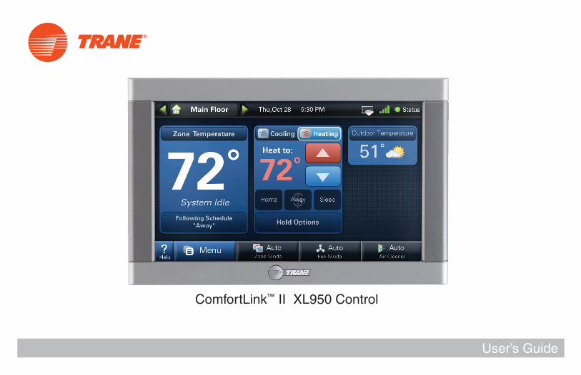
Features Include...
• Large Color Display
• Simple Programming
• Weather Forecast (via wireless home network)
• Allergy Clean/Quick Clean Cycles
• Interactive Touchscreen
• 1-Touch Presets
• Built-in Help Screens
• Operating Runtime Analysis
• System Alerts
• Lock Screen Security
• Custom Screen Options
• Screen Savers
• Five Year Limited Warranty
The ComfortLink™ II control integrates home comfort into your personal lifestyle like nothing you’ve ever seen before.
Amazingly versatile,incredibly advanced
3 3
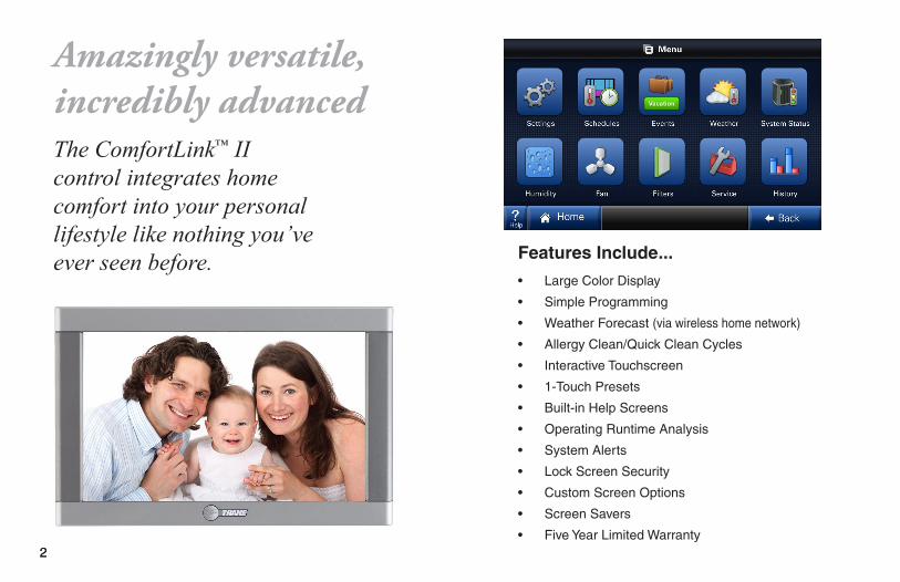
Easy to useThe simple design and easy to follow functions of this control make it the most intuitive and easy to use control available. Just touch the screen to try out the functionality and make opera-tional changes to the system in your home.
Help SystemOn-screen notes provide addition-al details. When more information is needed, context sensitive help is only a button touch away.
Scheduling Scheduling setup is made easy with the use of an on-screen wizard that walks you through the process.
1-Touch Presets Cooling and Heating presets al-low you to change your in-home temperatures with the touch of abutton.
Use only your fingertips to touch the touchscreen. Using any other implement can damage the screen.
CAUTION!
Use only a soft damp cloth to clean the screen.
CAUTION!
CustomizableCustomize the screen to suit your unique needs. You can setup shortcuts and an easy access dashboard on the Home screen. You can change the colors, and enjoy a photo slideshow.
Table of ContentsIntroduction ............................................... 1-4Buttons and Navigations .............................. 5System, Fan, & Air Cleaner Modes .......... 6-7Scheduling/Programming ......................... 8-9Loading and Viewing Photos ................ 10-11Screen Saver Settings ............................... 12Commonly Used Features ......................... 13Naming your System ................................. 13Dealer Information Screen ......................... 13Setting Time and Date ............................... 14Security Options ........................................ 14Runtime History ......................................... 141-Touch Presets ......................................... 14Customize Your Home Screen ................... 15Humidity ..................................................... 15Wireless Network Setup ....................... 16-19Advanced Networking Information ........ 20-23Multi-System Control ............................ 24-25Wireless Registration ............................ 26-27Schlage LiNK Enrollment ........................... 27Software Upgrades .................................... 28Troubleshooting .................................... 29-30Index .......................................................... 30Warranty .................................................... 31
4
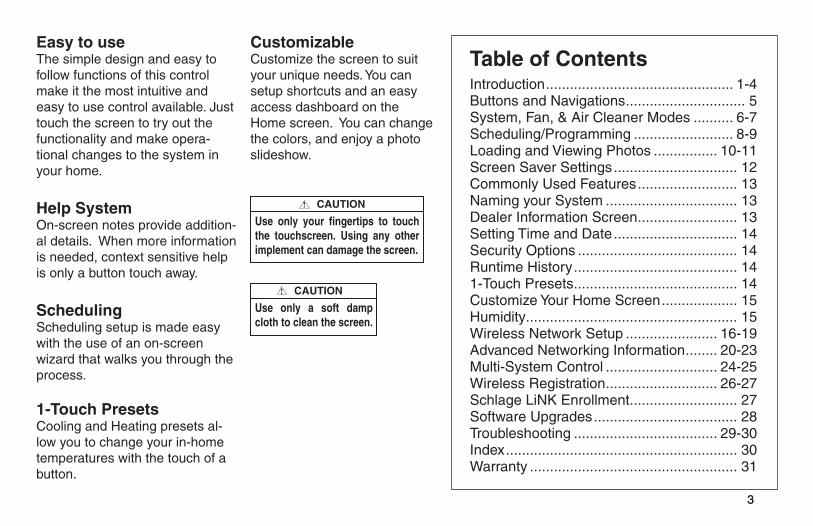
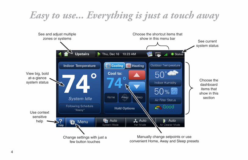
Choose the shortcut items that show in this menu bar
See and adjust multiple zones or systems
Change settings with just a few button touches
Manually change setpoints or useconvenient Home, Away and Sleep presets
View big, bold at-a-glance
system status
See current system status
Use contextsensitive
help
Choose the dashboard items that
show in this section
Easy to use... Everything is just a touch away
5
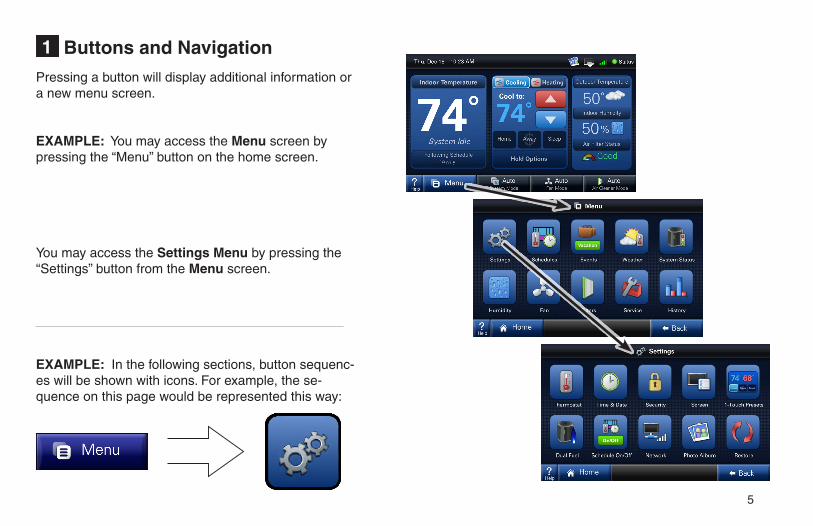
Buttons and Navigation1
Pressing a button will display additional information or a new menu screen.
EXAMPLE: You may access the Menu screen by pressing the “Menu” button on the home screen.
You may access the Settings Menu by pressing the “Settings” button from the Menu screen.
EXAMPLE: In the following sections, button sequenc-es will be shown with icons. For example, the se-quence on this page would be represented this way:
6
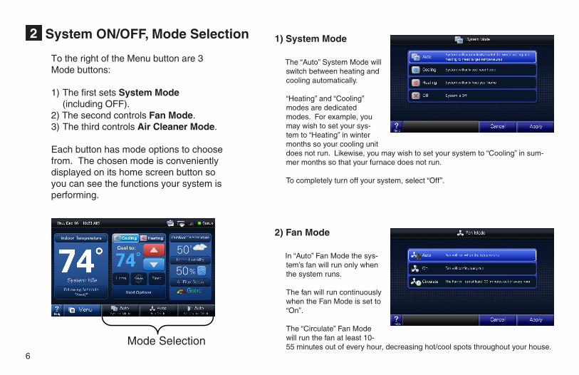
System ON/OFF, Mode Selection2
Mode Selection
To the right of the Menu button are 3 Mode buttons:
1) The first sets System Mode (including OFF). 2) The second controls Fan Mode.3) The third controls Air Cleaner Mode.
Each button has mode options to choose from. The chosen mode is conveniently displayed on its home screen button so you can see the functions your system is performing.
1) System Mode
The “Auto” System Mode will switch between heating and cooling automatically.
“Heating” and “Cooling” modes are dedicated modes. For example, you may wish to set your sys-tem to “Heating” in winter months so your cooling unit does not run. Likewise, you may wish to set your system to “Cooling” in sum-mer months so that your furnace does not run.
To completely turn off your system, select “Off”.
2) Fan Mode
In “Auto” Fan Mode the sys-tem’s fan will run only when the system runs.
The fan will run continuously when the Fan Mode is set to “On”.
The “Circulate” Fan Mode will run the fan at least 10-55 minutes out of every hour, decreasing hot/cool spots throughout your house.
7
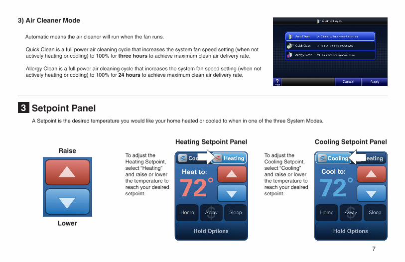
Setpoint Panel3
3) Air Cleaner Mode
Automatic means the air cleaner will run when the fan runs.
Quick Clean is a full power air cleaning cycle that increases the system fan speed setting (when not actively heating or cooling) to 100% for three hours to achieve maximum clean air delivery rate.
Allergy Clean is a full power air cleaning cycle that increases the system fan speed setting (when not actively heating or cooling) to 100% for 24 hours to achieve maximum clean air delivery rate.
Cooling Setpoint PanelHeating Setpoint PanelRaise
Lower
To adjust the Heating Setpoint, select “Heating” and raise or lower the temperature to reach your desired setpoint.
To adjust the Cooling Setpoint, select “Cooling” and raise or lower the temperature to reach your desired setpoint.
A Setpoint is the desired temperature you would like your home heated or cooled to when in one of the three System Modes.
8
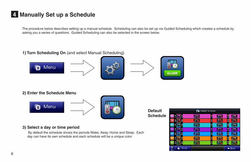
Manually Set up a Schedule4
1) Turn Scheduling On (and select Manual Scheduling)
2) Enter the Schedule Menu
3) Select a day or time period By default the schedule shows the periods Wake, Away, Home and Sleep. Each
day can have its own schedule and each schedule will be a unique color.
DefaultSchedule
The procedure below describes setting up a manual schedule. Scheduling can also be set up via Guided Scheduling which creates a schedule by asking you a series of questions. Guided Scheduling can also be selected in the screen below.
9
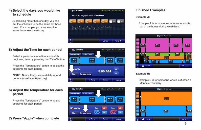
4) Select the days you would like to schedule
By selecting more than one day, you can set the schedule to be the same for those days. For example, you may keep the same hours each weekday .
Finished Examples:
Example A:
Example A is for someone who works and is out of the house during weekdays.
Example B:
Example B is for someone who is out of town Monday–Thursday.
5) Adjust the Time for each period
Select a period one at a time and set its beginning time by pressing the “Time” button.
Press the “Temperature” button to adjust the setpoints for each period.
NOTE: Notice that you can delete or add periods (maximum 6 per day).
6) Adjust the Temperature for each period
Press the “Temperature” button to adjust setpoints for each period.
7) Press “Apply” when complete

10
Using Photos5
Notch at top
Using an SD Card
Insert the SD Card at the bottom right hand side of the control, taking care to keep the card’s “notch” in the orientation shown.
NOTE: The card must remain inserted to view the photos and the SD card must remain “unlocked.”
You can set up a photo album and a screen saver using your own photos.
Photo AlbumView and set up your photo album.
Required Photo Formats:
Photos on your SD card must be in .jpg, .jpeg, .bmp, .png, or .gif formats and each photo must be less than 3MB in file size.
Recommended SD Cards:
SD, SDHCSD Adapter – microSD, miniSD, microSDHC, mini SDHC
11
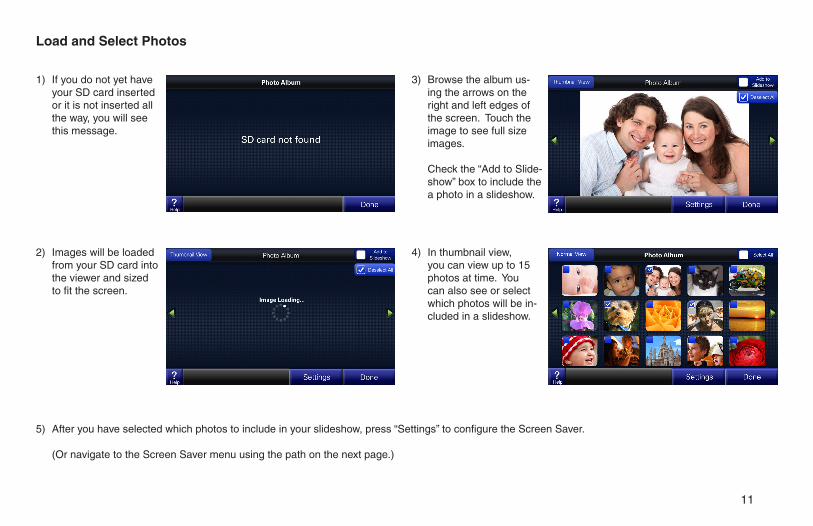
3) Browse the album us-ing the arrows on the right and left edges of the screen. Touch the image to see full size images.
Check the “Add to Slide-show” box to include the a photo in a slideshow.
1) If you do not yet have your SD card inserted or it is not inserted all the way, you will see this message.
2) Images will be loaded from your SD card into the viewer and sized to fit the screen.
4) In thumbnail view, you can view up to 15 photos at time. You can also see or select which photos will be in-cluded in a slideshow.
5) After you have selected which photos to include in your slideshow, press “Settings” to configure the Screen Saver.
(Or navigate to the Screen Saver menu using the path on the next page.)
Load and Select Photos
12
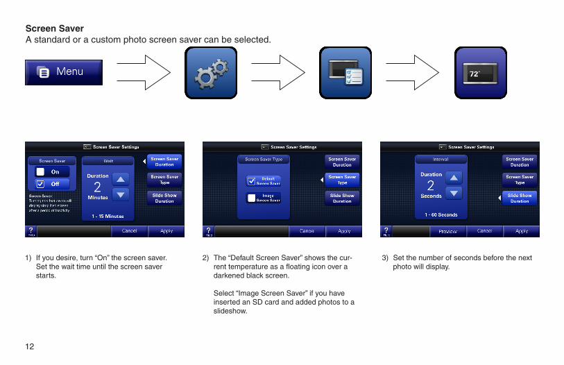
1) If you desire, turn “On” the screen saver. Set the wait time until the screen saver
starts.
2) The “Default Screen Saver” shows the cur-rent temperature as a floating icon over a darkened black screen.
Select “Image Screen Saver” if you have inserted an SD card and added photos to a slideshow.
3) Set the number of seconds before the next photo will display.
Screen SaverA standard or a custom photo screen saver can be selected.
13
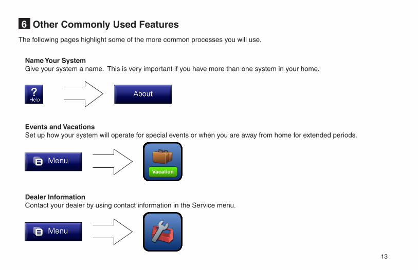
Other Commonly Used Features6
The following pages highlight some of the more common processes you will use.
Events and VacationsSet up how your system will operate for special events or when you are away from home for extended periods.
Name Your SystemGive your system a name. This is very important if you have more than one system in your home.
Dealer InformationContact your dealer by using contact information in the Service menu.
14
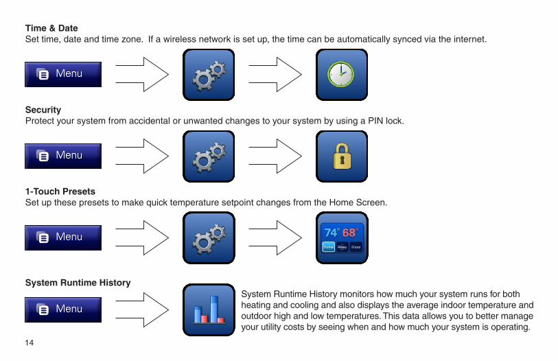
1-Touch PresetsSet up these presets to make quick temperature setpoint changes from the Home Screen.
SecurityProtect your system from accidental or unwanted changes to your system by using a PIN lock.
Time & DateSet time, date and time zone. If a wireless network is set up, the time can be automatically synced via the internet.
System Runtime HistorySystem Runtime History monitors how much your system runs for both heating and cooling and also displays the average indoor temperature and outdoor high and low temperatures. This data allows you to better manage your utility costs by seeing when and how much your system is operating.
15
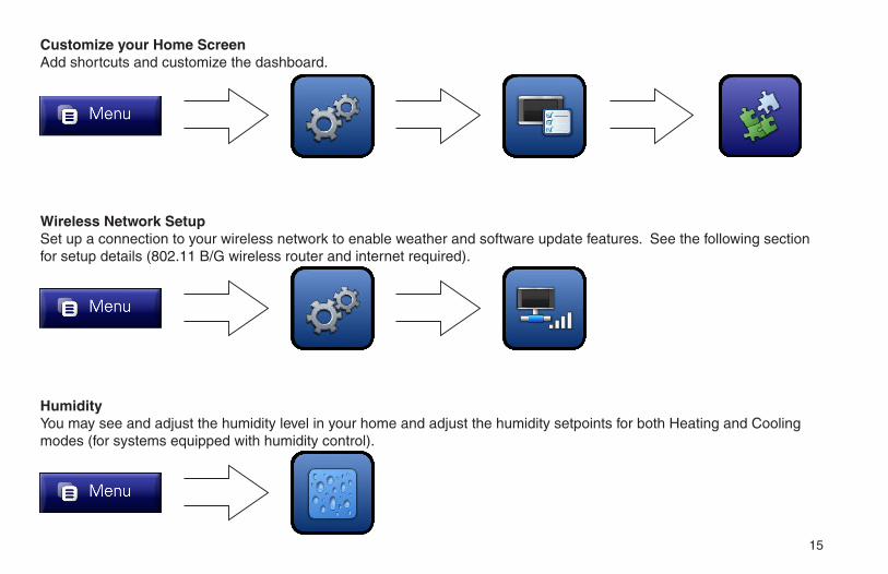
Customize your Home ScreenAdd shortcuts and customize the dashboard.
Wireless Network SetupSet up a connection to your wireless network to enable weather and software update features. See the following section for setup details (802.11 B/G wireless router and internet required).
HumidityYou may see and adjust the humidity level in your home and adjust the humidity setpoints for both Heating and Cooling modes (for systems equipped with humidity control).

16
Optional Wireless Networking7
Enabling wireless networking brings addi-tional functionality to your control.
NOTE: On a normally configured network, familiarity with a personal wireless network is helpful but not necessarily required for installation.
If your personal wireless network is a secure network, you will need the password.
IMPORTANT:
After wireless networking is enabled, you will need to register your system with a valid email address before the weather data will be displayed.
1. Your control can access real-time weather conditions, fore-casts and alerts.
2. When you have multiple systems in your home, each control can see and manage the others.
NOTE: In a Multi-System envi-ronment, it is recommended to name each control before en-abling wireless networking.
3. You can download software up-dates for efficient operation and the ability to use new features as soon as they are released.
17
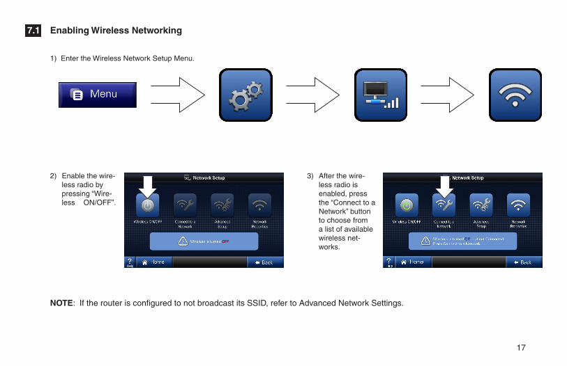
2) Enable the wire-less radio by pressing “Wire-less ON/OFF”.
3) After the wire-less radio is enabled, press the “Connect to a Network” button to choose from a list of available wireless net-works.
Enabling Wireless Networking7.1
1) Enter the Wireless Network Setup Menu.
NOTE: If the router is configured to not broadcast its SSID, refer to Advanced Network Settings.
18
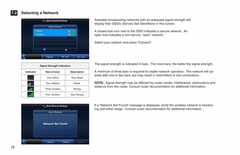
The signal strength is indicated in bars. The more bars, the better the signal strength.
A minimum of three bars is required for stable network operation. The network will op-erate with one or two bars, but may result in intermittent or lost connections.
NOTE: Signal strength may be affected by router model, interference, obstructions and distance from the router. Consult router documentation for additional information.
Available broadcasting networks with an adequate signal strength will display their SSIDs (Service Set IDentifiers) in this screen.
A closed lock icon next to the SSID indicates a secure network. An open lock indicates a non-secure, “open” network.
Select your network and press “Connect”.
If a “Network Not Found” message is displayed, verify the wireless network is function-ing and within range. Consult router documentation for additional information.
Signal Strength Indicators
Indicator Bars (Color) Description
One (Red) Very Weak
Two (Yellow) Weak
Three (Green) Strong
Four (Green) Very Strong
Selecting a Network7.2
19
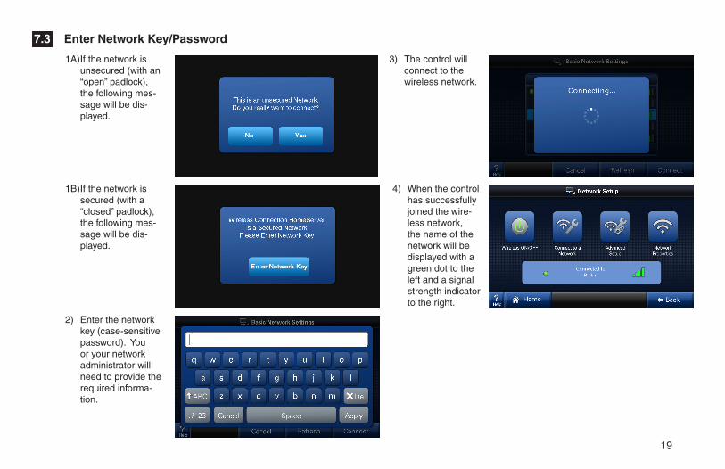
1A) If the network is unsecured (with an “open” padlock), the following mes-sage will be dis-played.
2) Enter the network key (case-sensitive password). You or your network administrator will need to provide the required informa-tion.
1B) If the network is secured (with a “closed” padlock), the following mes-sage will be dis-played.
3) The control will connect to the wireless network.
4) When the control has successfully joined the wire-less network, the name of the network will be displayed with a green dot to the left and a signal strength indicator to the right.
Enter Network Key/Password7.3

20
Advanced networking will be required in the following two instances:
1. When connecting to a non-broadcast network2. When configuring a static IP address
Advanced Networking Information7.4
Enter the Advanced Network Setup Menu.
IMPORTANT:
The Advanced Network screens are intended for individuals with networking familiarity.
You or your network administrator will need to provide the required information.
If any of this information is unknown or for questions specific to the wireless router, please consult the router documentation or your network administrator.
21
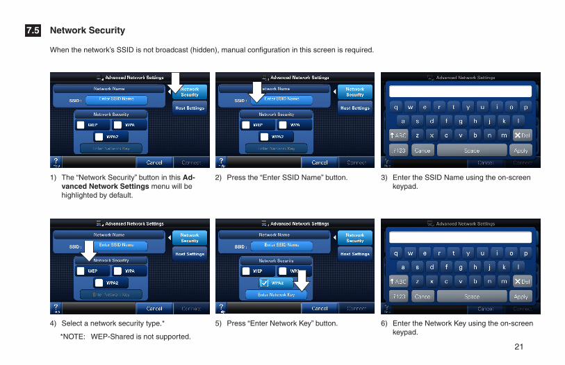
6) Enter the Network Key using the on-screen keypad.
5) Press “Enter Network Key” button.
2) Press the “Enter SSID Name” button.1) The “Network Security” button in this Ad-vanced Network Settings menu will be highlighted by default.
4) Select a network security type.*
*NOTE: WEP-Shared is not supported.
3) Enter the SSID Name using the on-screen keypad.
When the network’s SSID is not broadcast (hidden), manual configuration in this screen is required.
Network Security7.5
22
Host Settings7.6
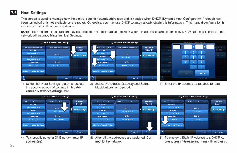
This screen is used to manage how the control obtains network addresses and is needed when DHCP (Dynamic Host Configuration Protocol) has been turned off or is not available on the router. Otherwise, you may use DHCP to automatically obtain this information. This manual configuration is required if a static IP address is desired.
NOTE: No additional configuration may be required in a non-broadcast network where IP addresses are assigned by DHCP. You may connect to the network without modifying the Host Settings.
3) Enter the IP address as required for each.
4) To manually select a DNS server, enter IP address(es).
1) Select the “Host Settings” button to access the second screen of settings in this Ad-vanced Network Settings menu.
2) Select IP Address, Gateway and Subnet Mask buttons as required.
5) After all the addresses are assigned, Con-nect to the network.
6) To change a Static IP Address to a DHCP Ad-dress, press “Release and Renew IP Address”.
23
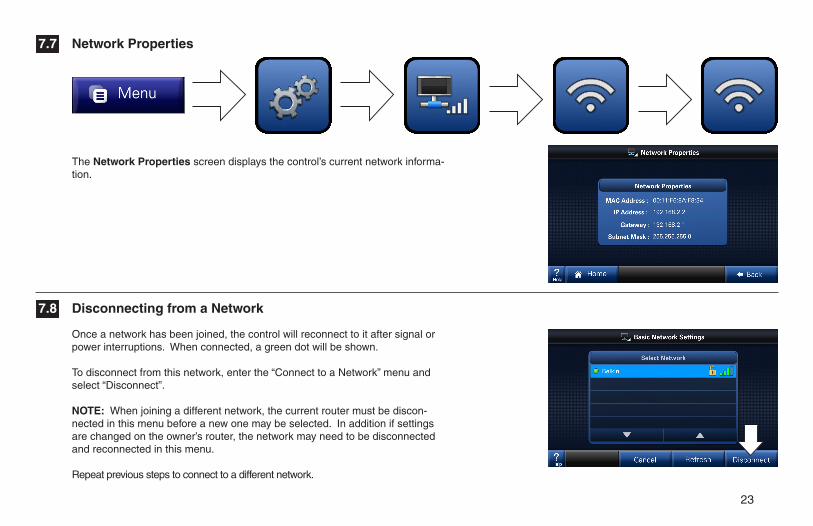
Once a network has been joined, the control will reconnect to it after signal or power interruptions. When connected, a green dot will be shown.
To disconnect from this network, enter the “Connect to a Network” menu and select “Disconnect”.
NOTE: When joining a different network, the current router must be discon-nected in this menu before a new one may be selected. In addition if settings are changed on the owner’s router, the network may need to be disconnected and reconnected in this menu.
Repeat previous steps to connect to a different network.
The Network Properties screen displays the control’s current network informa-tion.
Network Properties
Disconnecting from a Network
7.7
7.8
24
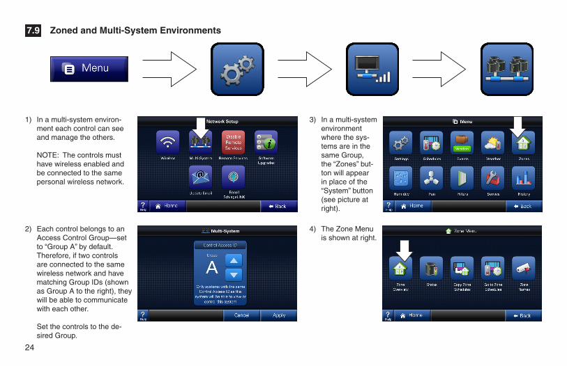
Zoned and Multi-System Environments7.9
1) In a multi-system environ-ment each control can see and manage the others.
NOTE: The controls must have wireless enabled and be connected to the same personal wireless network.
2) Each control belongs to an Access Control Group—set to “Group A” by default. Therefore, if two controls are connected to the same wireless network and have matching Group IDs (shown as Group A to the right), they will be able to communicate with each other.
Set the controls to the de-sired Group.
4) The Zone Menu is shown at right.
3) In a multi-system environment where the sys-tems are in the same Group, the “Zones” but-ton will appear in place of the “System” button (see picture at right).
25
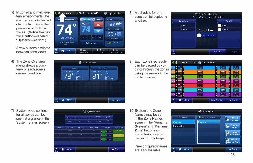
6) The Zone Overview menu shows a quick view of each zone’s current condition.
7) System wide settings for all zones can be seen at a glance in the System Status screen.
10) System and Zone Names may be set in the Zone Names screen. The “Rename System” and “Rename Zone” buttons al-low entering custom names from a keypad.
Pre-configured names are also available.
8) A schedule for one zone can be copied to another.
5) In zoned and multi-sys-tem environments, the main screen display will change to indicate the presence of multiple zones. (Notice the new zone button—labeled “Upstairs”—at right.)
Arrow buttons navigate between zone views.
9) Each zone’s schedule can be viewed by cy-cling through the zones using the arrows in the top left corner.
26
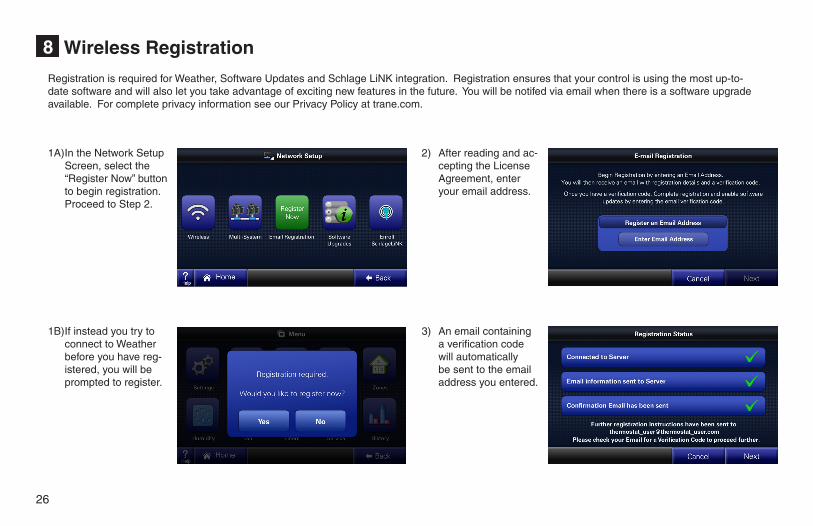
Wireless Registration8
1A) In the Network Setup Screen, select the “Register Now” button to begin registration. Proceed to Step 2.
1B) If instead you try to connect to Weather before you have reg-istered, you will be prompted to register.
2) After reading and ac-cepting the License Agreement, enter your email address.
3) An email containing a verification code will automatically be sent to the email address you entered.
Registration is required for Weather, Software Updates and Schlage LiNK integration. Registration ensures that your control is using the most up-to-date software and will also let you take advantage of exciting new features in the future. You will be notifed via email when there is a software upgrade available. For complete privacy information see our Privacy Policy at trane.com.
27
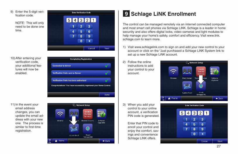
Schlage LiNK Enrollment9
10) After entering your verification code, your additional fea-tures will now be enabled.
11) In the event your email address changes, you can update the email ad-dress with your new one. The process is similar to first-time registration.
9) Enter the 5-digit veri-fication code.
NOTE: This will only need to be done one time.
The control can be managed remotely via an internet connected computer and most smart cell phones via Schlage LiNK. Schlage is a leader in home securiity and also offers digital locks, video cameras and light modules to help manage your home’s safety, comfort and efficiency. Visit www.link.schlage.com to learn more.
1) Visit www.schlagelink.com to sign on and add your new control to your account or click on the “Just purchased a Schlage LiNK System link to set up a new Schlage LiNK account.
2) Follow the online instructions to add your control to your account.
3) When you add your control to your online account, a verification PIN code is generated.
Enter that PIN code to
enroll your control and enjoy the comfort, sav-ings and convenience Schlage LiNK offers.
28
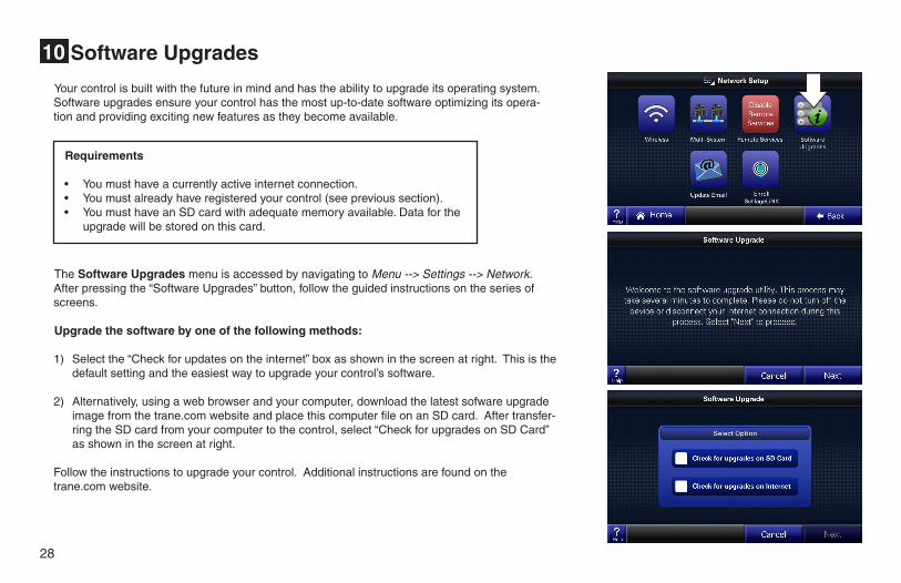
Software Upgrades10
Your control is built with the future in mind and has the ability to upgrade its operating system. Software upgrades ensure your control has the most up-to-date software optimizing its opera-tion and providing exciting new features as they become available.
The Software Upgrades menu is accessed by navigating to Menu --> Settings --> Network. After pressing the “Software Upgrades” button, follow the guided instructions on the series of screens.
Upgrade the software by one of the following methods:
1) Select the “Check for updates on the internet” box as shown in the screen at right. This is the default setting and the easiest way to upgrade your control’s software.
2) Alternatively, using a web browser and your computer, download the latest sofware upgrade image from the trane.com website and place this computer file on an SD card. After transfer-ring the SD card from your computer to the control, select “Check for upgrades on SD Card” as shown in the screen at right.
Follow the instructions to upgrade your control. Additional instructions are found on the trane.com website.
Requirements
• Youmusthaveacurrentlyactiveinternetconnection.• Youmustalreadyhaveregisteredyourcontrol(seeprevioussection).• YoumusthaveanSDcardwithadequatememoryavailable.Dataforthe
upgrade will be stored on this card.
29
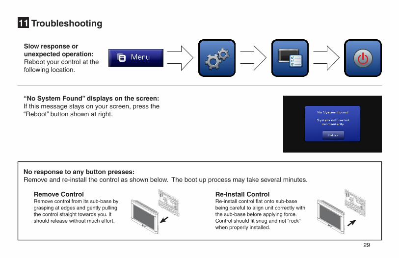
Troubleshooting11
Slow response or unexpected operation:Reboot your control at the following location.
“No System Found” displays on the screen:If this message stays on your screen, press the “Reboot” button shown at right.
No response to any button presses:Remove and re-install the control as shown below. The boot up process may take several minutes.
Re-Install Control Re-install control flat onto sub-base being careful to align unit correctly with the sub-base before applying force. Control should fit snug and not “rock” when properly installed.
Remove Control Remove control from its sub-base by grasping at edges and gently pulling the control straight towards you. It should release without much effort.
30
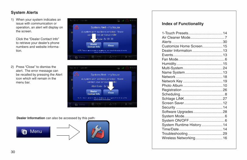
Index of Functionality
1-Touch Presets ..................................14Air Cleaner Mode ..................................7Alerts ..................................................30Customize Home Screen ....................15Dealer Information ..............................13Events .................................................13Fan Mode..............................................6Humidity ..............................................15Multi-System .......................................24Name System .....................................13Network ..............................................18Network Key .......................................19Photo Album .......................................10Registration ........................................26Scheduling ............................................8Schlage LiNK ......................................27Screen Saver ......................................12Security ..............................................14Software Upgrades .............................28System Mode ........................................6System ON/OFF ...................................6System Runtime History .....................14Time/Date ...........................................14Troubleshooting ..................................29Wireless Networking ...........................16
2) Press “Close” to dismiss the alert. The error message can be recalled by pressing the Alert icon which will remain in the menu bar.
Dealer Information can also be accessed by this path:
System Alerts
1) When your system indicates an issue with communication or operation, an alert will display on the screen.
Click the “Dealer Contact Info” to retrieve your dealer’s phone numbers and website informa-tion.
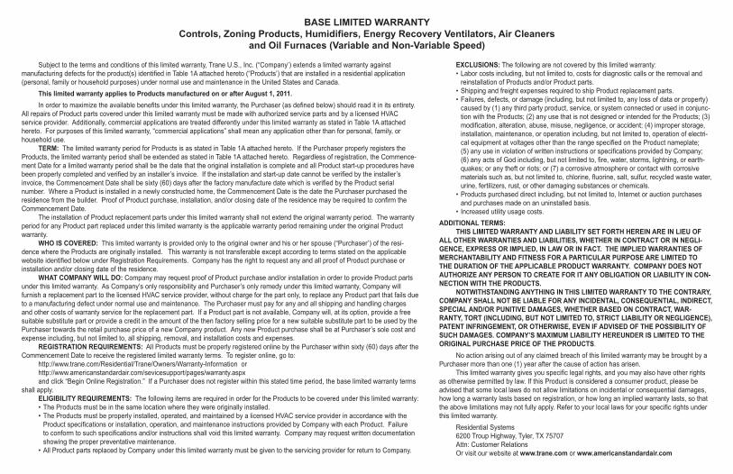
BASE LIMITED WARRANTY Controls, Zoning Products, Humidifiers, Energy Recovery Ventilators, Air Cleaners
and Oil Furnaces (Variable and Non-Variable Speed)
Subject to the terms and conditions of this limited warranty, Trane U.S., Inc. (“Company’) extends a limited warranty against manufacturing defects for the product(s) identified in Table 1A attached hereto (“Products’) that are installed in a residential application (personal, family or household purposes) under normal use and maintenance in the United States and Canada.
This limited warranty applies to Products manufactured on or after August 1, 2011.In order to maximize the available benefits under this limited warranty, the Purchaser (as defined below) should read it in its entirety.
All repairs of Product parts covered under this limited warranty must be made with authorized service parts and by a licensed HVAC service provider. Additionally, commercial applications are treated differently under this limited warranty as stated in Table 1A attached hereto. For purposes of this limited warranty, “commercial applications” shall mean any application other than for personal, family, or household use.
TERM: The limited warranty period for Products is as stated in Table 1A attached hereto. If the Purchaser properly registers the Products, the limited warranty period shall be extended as stated in Table 1A attached hereto. Regardless of registration, the Commence-ment Date for a limited warranty period shall be the date that the original installation is complete and all Product start-up procedures have been properly completed and verified by an installer’s invoice. If the installation and start-up date cannot be verified by the installer’s invoice, the Commencement Date shall be sixty (60) days after the factory manufacture date which is verified by the Product serial number. Where a Product is installed in a newly constructed home, the Commencement Date is the date the Purchaser purchased the residence from the builder. Proof of Product purchase, installation, and/or closing date of the residence may be required to confirm the Commencement Date.
The installation of Product replacement parts under this limited warranty shall not extend the original warranty period. The warranty period for any Product part replaced under this limited warranty is the applicable warranty period remaining under the original Product warranty.
WHO IS COVERED: This limited warranty is provided only to the original owner and his or her spouse (“Purchaser’) of the resi-dence where the Products are originally installed. This warranty is not transferable except according to terms stated on the applicable website identified below under Registration Requirements. Company has the right to request any and all proof of Product purchase or installation and/or closing date of the residence.
WHAT COMPANY WILL DO: Company may request proof of Product purchase and/or installation in order to provide Product parts under this limited warranty. As Company’s only responsibility and Purchaser’s only remedy under this limited warranty, Company will furnish a replacement part to the licensed HVAC service provider, without charge for the part only, to replace any Product part that fails due to a manufacturing defect under normal use and maintenance. The Purchaser must pay for any and all shipping and handling charges and other costs of warranty service for the replacement part. If a Product part is not available, Company will, at its option, provide a free suitable substitute part or provide a credit in the amount of the then factory selling price for a new suitable substitute part to be used by the Purchaser towards the retail purchase price of a new Company product. Any new Product purchase shall be at Purchaser’s sole cost and expense including, but not limited to, all shipping, removal, and installation costs and expenses.
REGISTRATION REQUIREMENTS: All Products must be properly registered online by the Purchaser within sixty (60) days after the Commencement Date to receive the registered limited warranty terms. To register online, go to:
http://www.trane.com/Residential/Trane/Owners/Warranty-Information or http://www.americanstandardair.com/sevicesupport/pages/warranty.aspx and click “Begin Online Registration.” If a Purchaser does not register within this stated time period, the base limited warranty terms
shall apply. ELIGIBILITY REQUIREMENTS: The following items are required in order for the Products to be covered under this limited warranty:• The Products must be in the same location where they were originally installed.• The Products must be properly installed, operated, and maintained by a licensed HVAC service provider in accordance with the
Product specifications or installation, operation, and maintenance instructions provided by Company with each Product. Failure to conform to such specifications and/or instructions shall void this limited warranty. Company may request written documentation showing the proper preventative maintenance.
• All Product parts replaced by Company under this limited warranty must be given to the servicing provider for return to Company.
EXCLUSIONS: The following are not covered by this limited warranty:• Labor costs including, but not limited to, costs for diagnostic calls or the removal and
reinstallation of Products and/or Product parts.• Shipping and freight expenses required to ship Product replacement parts.• Failures, defects, or damage (including, but not limited to, any loss of data or property)
caused by (1) any third party product, service, or system connected or used in conjunc-tion with the Products; (2) any use that is not designed or intended for the Products; (3) modification, alteration, abuse, misuse, negligence, or accident; (4) improper storage, installation, maintenance, or operation including, but not limited to, operation of electri-cal equipment at voltages other than the range specified on the Product nameplate; (5) any use in violation of written instructions or specifications provided by Company; (6) any acts of God including, but not limited to, fire, water, storms, lightning, or earth-quakes; or any theft or riots; or (7) a corrosive atmosphere or contact with corrosive materials such as, but not limited to, chlorine, fluorine, salt, sulfur, recycled waste water, urine, fertilizers, rust, or other damaging substances or chemicals.
• Products purchased direct including, but not limited to, Internet or auction purchases and purchases made on an uninstalled basis.
• Increased utility usage costs.ADDITIONAL TERMS:
THIS LIMITED WARRANTY AND LIABILITY SET FORTH HEREIN ARE IN LIEU OF ALL OTHER WARRANTIES AND LIABILITIES, WHETHER IN CONTRACT OR IN NEGLI-GENCE, EXPRESS OR IMPLIED, IN LAW OR IN FACT. THE IMPLIED WARRANTIES OF MERCHANTABILITY AND FITNESS FOR A PARTICULAR PURPOSE ARE LIMITED TO THE DURATION OF THE APPLICABLE PRODUCT WARRANTY. COMPANY DOES NOT AUTHORIZE ANY PERSON TO CREATE FOR IT ANY OBLIGATION OR LIABILITY IN CON-NECTION WITH THE PRODUCTS.
NOTWITHSTANDING ANYTHING IN THIS LIMITED WARRANTY TO THE CONTRARY, COMPANY SHALL NOT BE LIABLE FOR ANY INCIDENTAL, CONSEQUENTIAL, INDIRECT, SPECIAL AND/OR PUNITIVE DAMAGES, WHETHER BASED ON CONTRACT, WAR-RANTY, TORT (INCLUDING, BUT NOT LIMITED TO, STRICT LIABILITY OR NEGLIGENCE), PATENT INFRINGEMENT, OR OTHERWISE, EVEN IF ADVISED OF THE POSSIBILITY OF SUCH DAMAGES. COMPANY’S MAXIMUM LIABILITY HEREUNDER IS LIMITED TO THE ORIGINAL PURCHASE PRICE OF THE PRODUCTS.
No action arising out of any claimed breach of this limited warranty may be brought by a Purchaser more than one (1) year after the cause of action has arisen.
This limited warranty gives you specific legal rights, and you may also have other rights as otherwise permitted by law. If this Product is considered a consumer product, please be advised that some local laws do not allow limitations on incidental or consequential damages, how long a warranty lasts based on registration, or how long an implied warranty lasts, so that the above limitations may not fully apply. Refer to your local laws for your specific rights under this limited warranty.
Residential Systems6200 Troup Highway, Tyler, TX 75707Attn: Customer Relations Or visit our website at www.trane.com or www.americanstandardair.com

Table 1A: Warranty Time Periods COVERAGE TERMS FOR RESIDENTIAL APPLICATIONS: Pursuant to the Trane U.S., Inc. (“Company”) limited warranty terms and conditions, the following Products are covered for the base time periods as stated below (“Base Limited Warranty period”). If registered, the Base Limited Warranty Periods for certain products will be extended as stated below (“Registered Limited Warranty Period”). CONTROLS: *CONT200,*CONT401,*CONT402, *CONT600 &*CONT602 Base Limited Warranty Period: one (1) year Registered Limited Warranty Period: five (5) years
CONTROLS: *ZEMT500 *CONT800,*CONT802,*CONT803,*CONT900. *ZONE950 Base Limited Warranty Period: five (5) years Registered Limited Warranty Period: ten (10) years
ZONING PRODUCTS: *ZONE950, *ZONE940, *ZONE930, ZZONEPNLAC52Z, ZZONEEXPAC52Z, ZZSENSAL0400, BAYSEN01ATEMPA, BAY24VRP, ZDAMPRD, ZDAMPSM, ZDAMPBM, ZDAMPRRBase Limited Warranty Period: five (5) years Registered Limited Warranty Period: ten (10) years
HUMIDIFIERS: *HUMD200, *HUMD300 & *HUMD500 Base Limited Warranty Period: five (5) years Registered Limited Warranty Period: ten (10) years
ENERGY RECOVERY VENTILATOR (ERV): *ERVR100, *ERVR200 & *ERVR300 Base Limited Warranty Period: five (5) years Registered Limited Warranty Period: ten (10) years
AIR CLEANERS: TFD & AFD Base Limited Warranty Period: five (5) years Registered Limited Warranty Period: ten (10) years
VARIABLE SPEED OIL FURNACE: *HV-V, *LF-V, *LR-V,*DF-V Base Limited Warranty Period: Parts- five (5) years, Heat Exchanger - twenty (20) years Registered Limited Warranty Period: Parts - ten (10) years, Heat Exchanger - Lifetime
NON-VARIABLE SPEED OIL FURNACE: *HV, *LF, *LR,*DF Base Limited Warranty Period: Parts- five (5) years, Heat Exchanger - twenty (20) years Registered Limited Warranty Period: Parts - five (5) years, Heat Exchanger - Lifetime
SPECIFIC TERMS FOR COMMERCIAL APPLCIATIONS: Base Limited Warranty Period Applies for all controls, zoning products, humidifiers and ERV’s All Oil Furnaces: Parts - one (1) year, Heat Exchanger - twenty (20) years
*(First letter may be A or T)
08/11 32-5070-03The manufacturer has a policy of continuous product and product data improve-ment and it reserves the right to change design and specifications without notice.
6200 Troup HighwayTyler, TX 75707© 2011 Trane
FCC InformationThis equipment has been tested and found to comply with the limits for a Class B digital device, pursu-ant to Part 15 of the FCC Rules. These limits are designed to provide reasonable protection against harmful interference in a residential installation. This equipment generates, uses, and can radiate radio frequency energy and, if not installed and used in accordance with the instructions, may cause harmful interference to radio communications. However, there is no guarantee that interference will not occur in a particular installation. If this equipment does cause harmful interference to radio or television reception, which can be determined by turning the equipment off and on, the user is encouraged to try to correct the interference by one of the following measures:(1) Reorient or relocate the transceiver antenna. (2) Increase the separation between the equipment and transceiver. (3) Connect the equipment into an outlet on a circuit different from that to which the transceiver is connected. (4) Consult the dealer or an experienced radio/TV technician for help.
This device complies with Part 15 of the FCC Rules and Industry Canada. Operation is subject to the following two conditions: (1) This device may not cause harmful interference, and (2) This device must accept any interference received, including interference that may cause undesired operation.
FCC/IC Caution: Any changes or modifications not expressly approved by Trane could void the user’s authority to operate this equipment.
Important Note: To comply with the FCC RF exposure compliance requirements, no change to the antenna or the device is permitted. Any change to the antenna or the device could result in the device exceeding the RF exposure requirements and void user’s authority to operate the device. This device has been designed to operate with an internal PCB trace antenna.
To comply with IC RF exposure limits for general population/uncontrolled exposure, the module with fixed internal antenna must be installed to provide a separation distance of at least 20 cm from all persons and must not be collocated or operating in conjunction with any other antenna or transmitter.
TRANE U. S. INC. FCC ID: XVRZONE950TRXMODEL NUMBER IC: 6178D-ZONE950TRXTZONE950AC52Z