Embed Size (px)
Citation preview

Comfort 500 SSpindle drive operator for hinged gates
Installation Instructions

Page 2
Table 1: Drive unit dimensions
Overview of spindle drive unit for hinged gates
a b c d e f g
"Standard" version 535 465 300 816 27 140 120
"Long" version 735 565 400 1016 27 140 120
O1
OE OA OF
OB OC OD
a
b c
e
g
fg
A Spindle drive unitB Pivot - postC Pivot - gate wing, "open" positionD Pivot - gate wing, "closed" positionE Motor with positional sensor (speed registration)F Reference point
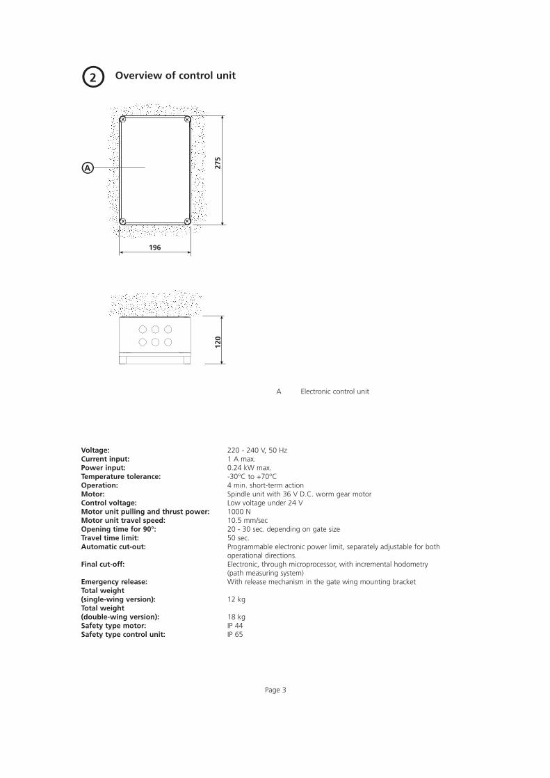
Overview of control unit
Page 3
O2
A Electronic control unit
Voltage: 220 - 240 V, 50 HzCurrent input: 1 A max.Power input: 0.24 kW max.Temperature tolerance: -30°C to +70°COperation: 4 min. short-term actionMotor: Spindle unit with 36 V D.C. worm gear motorControl voltage: Low voltage under 24 VMotor unit pulling and thrust power: 1000 NMotor unit travel speed: 10.5 mm/secOpening time for 90°: 20 - 30 sec. depending on gate sizeTravel time limit: 50 sec.Automatic cut-out: Programmable electronic power limit, separately adjustable for both
operational directions.Final cut-off: Electronic, through microprocessor, with incremental hodometry
(path measuring system)Emergency release: With release mechanism in the gate wing mounting bracketTotal weight(single-wing version): 12 kgTotal weight(double-wing version): 18 kgSafety type motor: IP 44Safety type control unit: IP 65
OA
196
275
120
Page 4
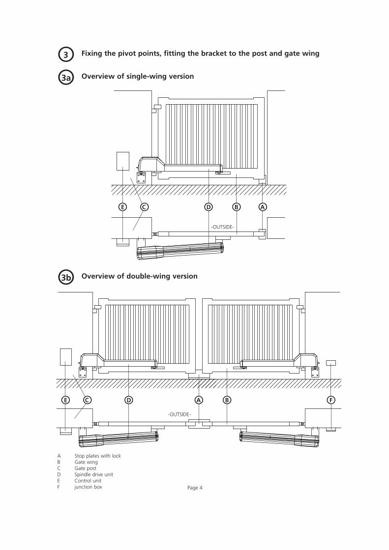
Fixing the pivot points, fitting the bracket to the post and gate wingO3
Overview of single-wing versionO3a
Overview of double-wing versionO3b
A Stop plates with lockB Gate wingC Gate postD Spindle drive unitE Control unitF junction box
OAOBOC ODOE
OA OBOC ODOE OF
-OUTSIDE-
-OUTSIDE-

Page 5
Fixing the pivot pointsO3c
OBO1
O2
* Distance „c“ for LH hinging (drive operator on left gate wing): drill hole 1* Distance „c“ for RH hinging (drive operator on right gate wing): drill hole 2
"Standard" version "Long" version
e = On-site building-in depth
A Post mounting bracketB Release box on the gate wing

Table 2: If the building-in dim. is less than 40 mm, use the „standard“ version of the spindle drive operator
Preferred dimensions for Preferred dimensions for Preferred dimensions for largest gate wing width <2000 gate wing width >2000 possible opening angle
Max. Openingangle
degrees110°105°100°
Page 6
Installing the fittingsO3c
Post mounting bracketIn order to ensure an opening angle of 90 degrees, the addition of measurements a + b should roughly correspond to thespindle stroke.a + b = 225 ... 285 mm for the „standard“ versiona + b = 240 ... 380 mm for the „long“ versionFor larger gate wings, the full working stroke should be used in order to limit the gate speed of the wing outer edges. Anchorthe post mounting bracket in the masonry (see fig. 3c).Building-in dimensions are specified in tables 2 + 3.If the on-site maximum building-in measurement „e max“ exceeds the specified values, then the drive operator must be setinto the masonry with the mounting bracket.Insert the hinged gate drive operator into the corresponding drill hole of the post mounting bracket and screw tight with anM10 hexagon nut.
Building-indim. emm
less than 00 - 20
20 - 40
amm125135155
bmm100100100
Openingangle
degrees90°90°90°
Openingtimesec.16
18,520
b max.mm160140115
Openingangle
degrees90°90°90°
Openingtimesec.212121
b min.mm140120115
Openingtimesec.222222
Table 3: Building-in dim. e = 40 ... 200 mm. Use the „long“ version of the spindle drive operator
Preferred dimensions for Preferred dimensions for Preferred dimensions for largest gate wing width <2000 gate wing width >2000 possible opening angle
Max. Openingangle
degrees120°115°110°100°100°100°95°90°
Building-indim. emm
40 - 6060 - 80
80 - 100100 - 120120 - 140140 - 160 160 - 180180 - 200
amm140160180200220240260280
bmm100100100100100100100100
Openingangle
degrees90°90°90°90°90°90°90°90°
Openingtimesec.18,519,521,52224262829
b max.mm240220200180160140120100
Openingangle
degrees90°90°90°90°90°90°90°90°
Openingtimesec.2828282929292929
b min.mm180180160160140120100100
Openingtimesec.2929292929292929

Page 7
180ºreversed
Fitting the release box to the gate wingTo establish the fixing points on the gate wing:With the spindle fully extended, connect the hinged gate operator in alignment with the release box and mark the position.Open the release box and drill 2 holes centrally within the elongated holes (6 mm dia. drill). Make the release box and the driveoperator secure, then make a test run. Carry out any necessary fine adjustment via the elongated holes. Remove rotary latch. Drill the outer hole and then screw the centrally located screw into this drill hole. This will prevent the boxfrom sliding sideways. Push rotary latch back in again. Place on washer and tighten hexagon nut until rotary latch is sluggish tooperate.
Release box open
L=b+c-10 (table 1, page 2)
Release box (for single-wing version, this may have to be reversed, depending on which side the gate is hinged)

Page 8
Overview of cable layoutO4
Single-wing gate constructionO4a
Double-wing gate constructionO4b
Secure the control unit to the post using wall plugs and screws, then plug into mains and make a test run. On completing thetest run, remove the mains lead with plug and have the control unit properly connected to the electricity supply by a qualifiedelectrician.
a Mains lead 240 V 50 Hz (e.g. NYY 3 x 1.5 on site by the customer)b Connecting cable for motor (by the factory)c Connecting cable for motor (by the factory or NYY - 0 9 x 1.5 with junction box - on site by the customer)d Control cable for push button, key switch (e.g. NYY - 0 6 x 1.5 on site by the customer).* If the control unit cannot be installed near the gate, please request a corresponding cable layout plan.
gate 1
gate 1 gate 2
ad
b
b
ad
d
c
Page 9
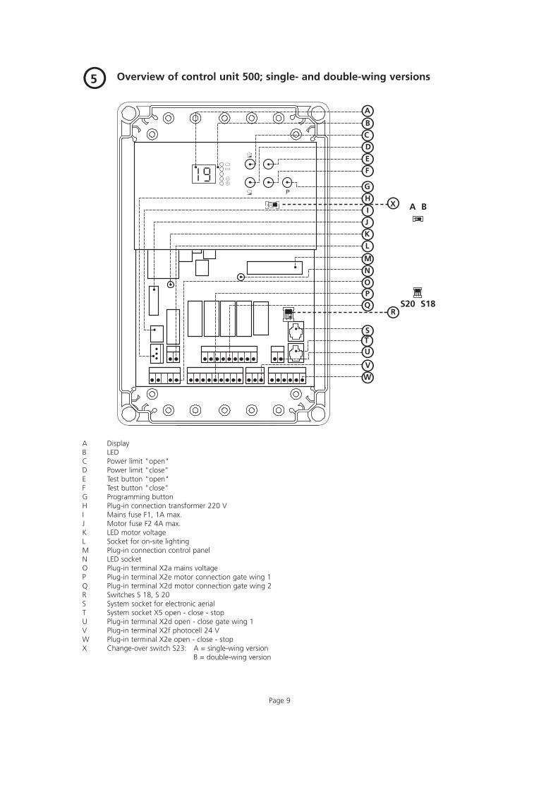
Overview of control unit 500; single- and double-wing versionsO5
A DisplayB LEDC Power limit "open"D Power limit "close"E Test button "open"F Test button "close"G Programming buttonH Plug-in connection transformer 220 VI Mains fuse F1, 1A max.J Motor fuse F2 4A max.K LED motor voltageL Socket for on-site lightingM Plug-in connection control panelN LED socketO Plug-in terminal X2a mains voltageP Plug-in terminal X2e motor connection gate wing 1Q Plug-in terminal X2d motor connection gate wing 2R Switches S 18, S 20S System socket for electronic aerialT System socket X5 open - close - stopU Plug-in terminal X2d open - close gate wing 1V Plug-in terminal X2f photocell 24 VW Plug-in terminal X2e open - close - stopX Change-over switch S23: A = single-wing version
B = double-wing version
OR
OAOB
OCOD
OE
OF
OGOH
OI
OJ
OKOL
OMONOOOP
OQ
OS
OT
OUOV
OW
OX A B
S20 S18

OBOA
OBOA
Page 10
Overview of connecting plan and circuit diagramO6
Control 500 connecting plan; single- and double-wing versionsO6a
A Connecting cable for drive unit gate 1B Connecting cable for drive unit gate 2
Page 11
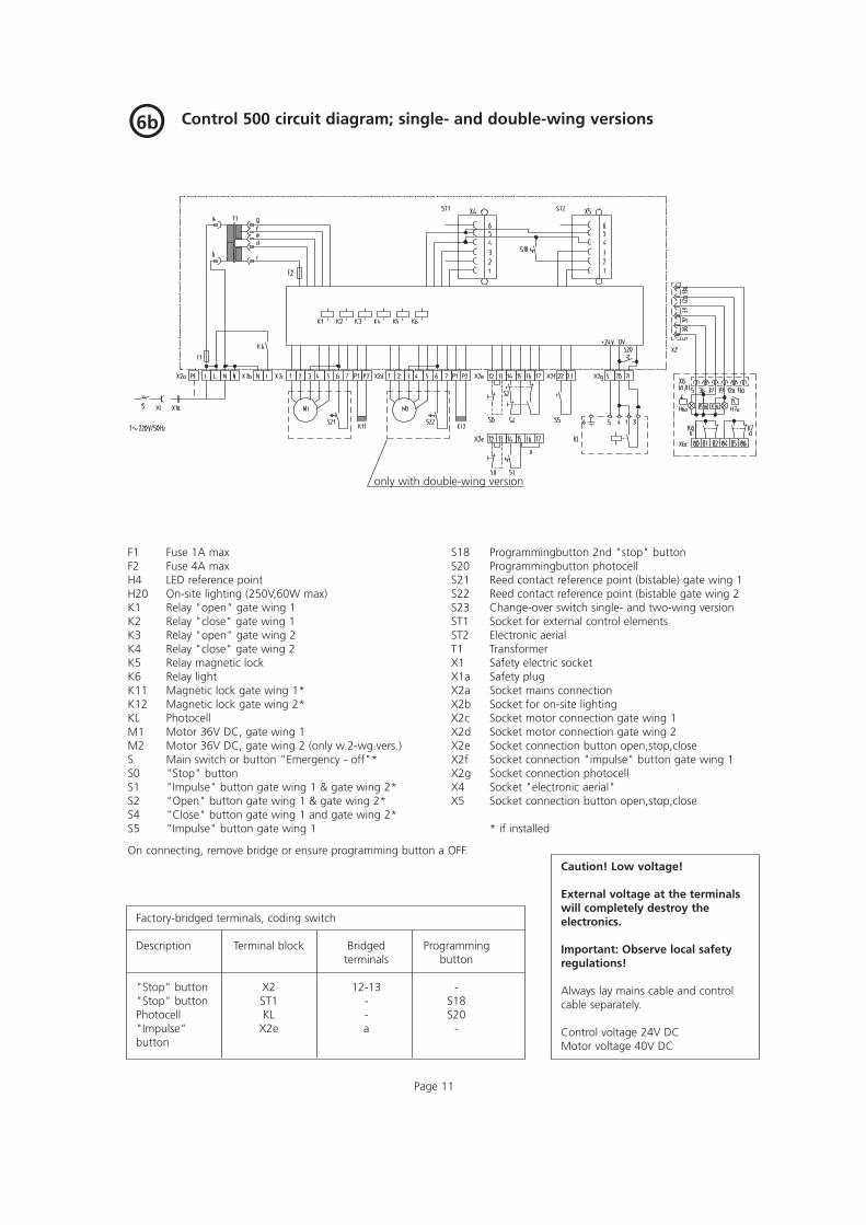
Control 500 circuit diagram; single- and double-wing versionsO6b
only with double-wing version
F1 Fuse 1A maxF2 Fuse 4A maxH4 LED reference pointH20 On-site lighting (250V,60W max)K1 Relay "open" gate wing 1K2 Relay "close" gate wing 1K3 Relay "open" gate wing 2K4 Relay "close" gate wing 2K5 Relay magnetic lockK6 Relay lightK11 Magnetic lock gate wing 1*K12 Magnetic lock gate wing 2*KL PhotocellM1 Motor 36V DC, gate wing 1M2 Motor 36V DC, gate wing 2 (only w.2-wg.vers.)S Main switch or button "Emergency - off"*S0 "Stop" buttonS1 "Impulse" button gate wing 1 & gate wing 2*S2 "Open" button gate wing 1 & gate wing 2*S4 "Close" button gate wing 1 and gate wing 2*S5 "Impulse" button gate wing 1
S18 Programmingbutton 2nd "stop" buttonS20 Programmingbutton photocellS21 Reed contact reference point (bistable) gate wing 1S22 Reed contact reference point (bistable gate wing 2S23 Change-over switch single- and two-wing versionST1 Socket for external control elementsST2 Electronic aerialT1 TransformerX1 Safety electric socketX1a Safety plugX2a Socket mains connectionX2b Socket for on-site lightingX2c Socket motor connection gate wing 1X2d Socket motor connection gate wing 2X2e Socket connection button open,stop,closeX2f Socket connection "impulse" button gate wing 1X2g Socket connection photocellX4 Socket "electronic aerial"X5 Socket connection button open,stop,close
* if installed
On connecting, remove bridge or ensure programming button a OFF.
Factory-bridged terminals, coding switch
Description Terminal block Bridged Programmingterminals button
"Stop" button X2 12-13 -"Stop" button ST1 - S18Photocell KL - S20"Impulse" X2e a -button
Caution! Low voltage!
External voltage at the terminalswill completely destroy theelectronics.
Important: Observe local safetyregulations!
Always lay mains cable and controlcable separately.
Control voltage 24V DCMotor voltage 40V DC

Page 12
Hand transmitter - Operation and accessories
A Battery - transmission control lightB Operating buttonsC Battery coverD Battery 3V CR 2032E Coding plug
• Please open the cover to change or insert the battery.Observe right poling when changing the battery.
Attention!Only operate the hand transmitter after you have made surethat there are neither persons nor objects in the operatingrange of the door.
Attention!- Children are not allowed to play with hand transmitters!- Batteries are excluded from warranty.
7
Module aerial8
Plug electronic aerial into the control unit (socket ST2) as shown in fig. 5, point "S". The range may vary with different digital security codings.
A Module aerialB Connecting lead with plug
OA
OB
OBOE
OE
OA
OD
OC

Page 13
Adjustment and codingO9
Putting into operationO9aSwitch on at the mains. LED lights up. After pressing the test buttons , the gate first moves in the direction of thereference point.If the drive unit is not installed, the swivel joint (fig 1 "C" must be held in a vertical position).Important: The limit stop is pre-set at the factory.The power limit can now be set in accordance with fig. 9c.Proceed with programming the remote control as illustrated in fig. 9d.Press the button to bring the gate into the final "open" position, then proceed with programming the final positions inaccordance with figs 9g/9h/9i. The programming procedure terminates automatically 30 seconds after the last entry, or can beterminated manually by pressing the "P" button (see figs. 9d/9e/9f/9g/9h and 9i).
Function displayO9b
Programming button
Power setting "open"
Power setting "close"
Test button "open"
Test button "close"
Final "open" position
Final "close" position
Remote control
Operate / program
Fault message
Setting the power limitsO9cPress the button to set the power limit "open", and press the button to set the power limit "close". The set value will be displayed.By repeatedly pressing the appropriate button, the power limit can be set in stages from 0 (most sensitive value) to 19 (pre-set value = 9).
Attention: To protect persons as well as the mechanical parts of the door and operator, set the power limit as sensitively as possible - on no account exeed 150 N (approx. 15 kg.)
"OPEN" direction "CLOSE" direction
The power limits are now set.

Press button "P" for 2 seconds"F" is displayedLED lights upLED flashes
Page 14
Coding the receiver for single-wing version (only with electronic aerial)O9d
Multi-channel hand transmitter:Press any button.
Display "-"Receiver coding is stored(only with electronic aerial)
Press button "P"
Press button "P" only with autom. timed return
Press button "P"
LED lights up
Programming is completed.

Page 15
Programming the receiver for two-wing version (only with electronic aerial)O9e
Press button "P" for 2 seconds"F" is displayedLED lights upLED flashes
Multi-channel hand transmitter:Press any button.
Display "-"Receiver programming is stored
Press button "P"
Press button "P"
Press button "P"
Press button "P"
Press button "P" only with autom.timed return
Press button "P"
LED lights up
Programming is completed.
Page 16
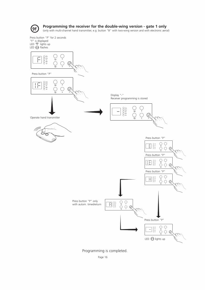
Programming the receiver for the double-wing version - gate 1 only(only with multi-channel hand transmitter, e.g. button "B" with two-wing version and with electronic aerial)O9f
Press button "P" for 2 seconds"F" is displayedLED lights upLED flashes
Press button "P"
Operate hand transmitter
Display "-"Receiver programming is stored
Press button "P"
Press button "P"
Press button "P"
Press button "P" onlywith autom. timedreturn
Press button "P"
LED lights up
Programming is completed.

Page 17
Setting the limit stops for single-wing version (gate must be in "OPEN" position)O9g
Press button "P" for 2 seconds"F" is displayedLED lights upLED flashes
Press button "P"
"E" is displayed
LED flashes
Press the button and keep it depressed until the gate has reached the final "close" position.Fine adjustment can be made by briefly pressing button or button which increases or reduces the travel distance of the gateby approx. 4 mm, without the gate moving!The final "close" position (limit stop) is stored.Press the button and keep it depressed until the gate has reached the final "open" position.Make fine adjustment as described above.The final "open" position (limit stop) is stored.
"OPEN" direction "CLOSE" direction
Press button "P" only with autom. timed return
Press button "P"
The limit stops are stored!
Programming is completed.

Page 18
Setting the limit stops for the double-wing version - gate 1 (gate must be in "OPEN" position)O9h
Press button "P" for 2 seconds"F" is displayedLED lights upLED flashes
Press button "P"
"E" is displayed
LED flashes
Press button and keep it depressed until the gate has reached the final "CLOSE" position.Fine adjustment an be made by briefly pressing button or button which increases or reduces the travel distance of the gate byapprox. 4 mm, without the gate moving!The final "CLOSE" position (limit stop) is stored.Press button and keep it depressed until the gate has reached the final "OPEN" position.Carry out fine adjustment as described above.The final "OPEN" position (limit stop) is stored.
"OPEN" direction "CLOSE" direction
Press button "P"
Press button "P"
Press button "P" only with autom. timedreturn
Programming is completed.
Press button "P"
Press button "P"
LED lights up

Page 19
Setting the limit stops for the double-wing version - gate 2O9i
Press button "P" for 2 seconds"F" is displayedLED lights upLED flashes
Press button "P"
Display "IE"
LED flashes
Press button and keep it depressed until the gate has reached the final "CLOSE" position.Fine adjustment can be made by briefly pressing button or button which increases or reduces the travel distance of the gate byapprox. 4 mm, without the gate moving!The final "CLOSE" position (limit stop) is stored.Press button and keep it depressed until the gate has reached the final "OPEN" position.Carry out fine adjustment as described above.The final "OPEN" position (limit stop) is stored.
"OPEN" direction "CLOSE" direction
Press button "P"
Press button "P" only with autom. timedreturn
Programming is completed.
Press button "P"
Press button "P"
LED lights up
Press button "P"

Page 20
Setting the time-delayed start for the double-wing versionO9j
Press button "P" for 2 seconds"F" is displayedLED lights upLED flashes
Press button "P"
Press button "P"
"H" is displayed
To program the time-delayed start, press button . The set value is displayed. By repeatedly pressing the button, the time delay can be set in stages from 0 to 19 (pre-set value = 2).
Press button "P"
Press button "P"
Press button "P"
Press button "P"
Display Time delay
0 0.5 sec.1 1.0 sec.2 2.0 sec.3 3.0 sec.4 4.0 sec.5 5.0 sec.6 6.0 sec.7 7.0 sec.8 8.0 sec.9 9.0 sec.
10 10.0 sec.11 11.0 sec.12 12.0 sec.13 13.0 sec.14 14.0 sec.15 15.0 sec.16 16.0 sec.17 17.0 sec.18 18.0 sec.19 19.0 sec.

Page 21
Programming the type of operationO9k Programming the light relay K6O9l
5 -B55 Impulse/stop/impulse in opposite direction
6 -B5/B6 Open/close with self-hold
7 -B5/B6 Open/close with self-hold and autom.timed return
8 -B5/B6 Open/close with self-hold and autom.timed return after driving past the site photocell
1 3-minute light phase
2 Flashing impulse
3 Gate operation
B55/B5/B6, B5/B6 with autom. timed return (pre-programmed at thefactory for sequential phase control B55 - do not alter unless necessary).
ProgrammingPress button while switching the unit on.
Select with button , and store selected setting with button "P"(after 30 seconds storage is automatic).
Display 7 or 8:Setting the "prewarning" or "gate open time" in accordance with fig. 9j.Connection of red traffic light H20 to terminal 1 and N (X2b as per fig. 6b)
(pre-set at the factory for 3-minute light phase,do not alter unless necessary).
ProgrammingPress button while switching the unit on.
Select with button and store selected settingby pressing button "P" (after 30 seconds storageis automatic).
If the self-hold function has been programmedon display 7 or 8, programming the light relaywill be ineffective.
Connect up site lighting, flashing light or beaconin accordance with the circuit diagram.
DisplayO9m
Function messages Fault messages
Display Function Display Display Fault
0 Stop button 8 Reference contact without function motor 1 / 2 Impulse OPEN 9 Hybrid photocell (RPM detecter) w/out function motor 1
(button/remote control)4 Impulse CLOSE 10 Power limit motor 1
(button/remote control)6 Driveway photocell 11 Operation time limitn7 Programming aborted 16 Power limit self-monitering not o.k.
17 Reference contact without function motor 218 Hybrid photocell (RPM detecter) w/out function motor 219 Power limit motor 2
Cancelling the settingsO9n
Press button "P" while switching the unit on."c" appears in the display.
Indicator/Display for operating mode 2 to 6
2 Flashing light
3 Revolving beacon
Indicator/Display for operating mode 7, 8, 9
Page 22
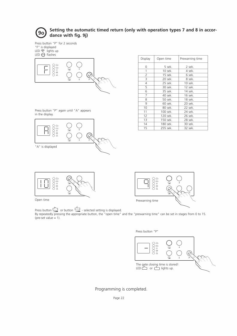
Setting the automatic timed return (only with operation types 7 and 8 in accor-dance with fig. 9j)O9o
Press button "P" for 2 seconds"F" is displayedLED lights upLED flashes
Press button "P" again until "A" appearsin the display.
Prewarning time
Press button or button - selected setting is displayed.By repeatedly pressing the appropriate button, the "open time" and the "prewarning time" can be set in stages from 0 to 15.(pre-set value = 1).
Press button "P"
The gate closing time is stored!LED or lights up.
"A" is displayed
Open time
Display Open time Prewarning time
0 5 sek. 2 sek.1 10 sek. 4 sek.2 15 sek. 6 sek.3 20 sek. 8 sek.4 25 sek. 10 sek.5 30 sek. 12 sek.6 35 sek. 14 sek.7 40 sek. 16 sek.8 50 sek. 18 sek.9 60 sek. 20 sek.
10 80 sek. 22 sek.11 100 sek. 24 sek.12 120 sek. 26 sek.13 150 sek. 28 sek.14 180 sek. 30 sek.15 255 sek. 32 sek.
Programming is completed.
Page 23
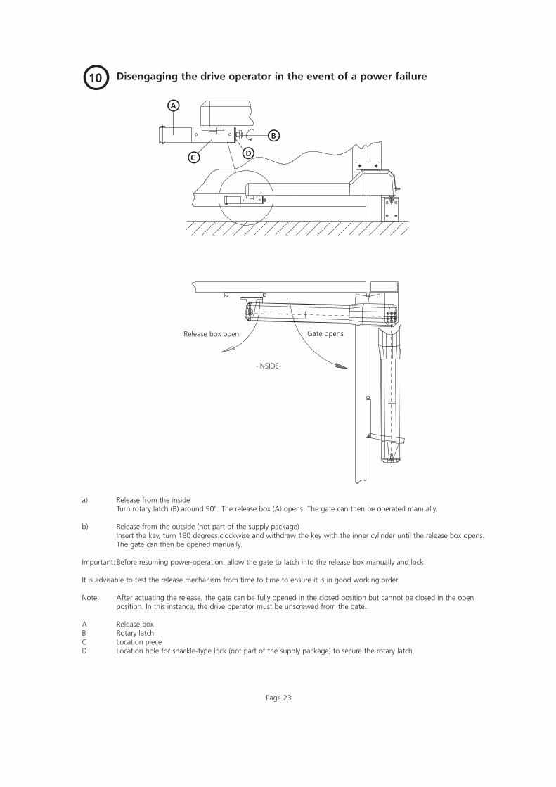
Disengaging the drive operator in the event of a power failureO10
a) Release from the insideTurn rotary latch (B) around 90°. The release box (A) opens. The gate can then be operated manually.
b) Release from the outside (not part of the supply package)Insert the key, turn 180 degrees clockwise and withdraw the key with the inner cylinder until the release box opens.The gate can then be opened manually.
Important: Before resuming power-operation, allow the gate to latch into the release box manually and lock.
It is advisable to test the release mechanism from time to time to ensure it is in good working order.
Note: After actuating the release, the gate can be fully opened in the closed position but cannot be closed in the openposition. In this instance, the drive operator must be unscrewed from the gate.
A Release boxB Rotary latchC Location pieceD Location hole for shackle-type lock (not part of the supply package) to secure the rotary latch.
OA
ODOCOB
Release box open Gate opens
-INSIDE-

Page 24
Fitting the electr. lock (optional accessory - to be used for gate wings wider than 2000 mm)
Electr. lock on single-wing hinged gate (electr. gate post lock, code no. 564 512, required)O11a
OA
OE
OB
10
128
Screw mounting plate (B) to gate wing and fit electr. lock(A). Secure striking plate (E) to the post. Wire the electr. lockin accordance with the circuit diagram.
Electr. lock on each wing of a double-wing gate construction (2 x electr.ground locks, code no. 564 509 and - if not provided - stop plate with opening to accept electr. lock bolt, code no. 564 518, required).
O11b
Screw mounting plate (B) to gate wing and fit electr. lock(A). Attach stop plate (C). Wire electr. lock in accordancewith the circuit diagram.
Electr. lock on double-wing hinged gate construction with stop bars (electr.ground lock, code no. 564 509 and - if not provided - stop plate with recessto accept bolt of electric lock, code no. 564 518, required).
O11c
OA OCOB
5
Screw mounting plate (B) to gate wing and fit electr. lock(A). Attach stop plate (C). Wire electr. lock in accordancewith the circuit diagram.
A Electr. lockB Mounting plateC Stop plateD Locking cylinderE Striking plate
O11
OD
- INSIDE -
5

Issue: 05.2003#8 008 826
Fault Cause Remedy
No green light on No voltage. Check mains supply.operation lamp. Check mains fuse F1.
Thermal protection is activated. Allow trafo to cool down.
Fault indicator Automatic cut-out set too sensitively. Adjust automatic cut-out to be less sensitive as flashing "red". Door operation too sluggish. Door blocks. per fig. 9c.display 10 or 19 Ensure door moves easily.
Display 9 or 18 Positional sensor is defective. Replace positional sensor in motor.Drive operateswithaot self-hold.
No function. Defective electronics. Disconnect drive unit from the mains. Remove electronic circuit boards and have them tested.
No reaction on "impulse" button bridged, e.g. due to Tempo ravily solate wired key switches or push impulse. short-circuit or wrong terminal connection. buttons to trace wiring fault.
Page 25
O12
Test Instructions (only for the specialist!)Trouble shooting:
1 -
GB
3600
7 -
M -
0.5
- 1
194
EN 55011EN 50081EN 50082ETS 300220
Changes reserved!