Embed Size (px)
Citation preview

Combined Heat and Power System
By
Ryan Christie, Ronald Stepanek, Nathan Duray, Joseph Mudd,
Cory Donavon and Jason Dikes
Team 11
Concept Generation Document
Submitted towards partial fulfillment of the requirements for
Mechanical Engineering Design – Fall 2012
Department of Mechanical Engineering
Northern Arizona University Flagstaff, AZ 86011

2
Table of Contents
Overview
3
Problem Statement
3
Concept Generation
3-4
Concepts
4-12
Weighting Factor Tree
13
Decision Matrix and Concept Selection
14
Creative Design
15
Timeline
16
Appendix
17
3
Overview This report on concept generation, for our combined heat and power system, includes the
following categories:
- A refined problem statement from Supreme Manufacturing
- Our initial brainstorming of ideas and concepts, compiled and explained in a
morphological chart
- Ten concepts we generated and the reasons why each of them may be a viable solution
- Our decision matrix which helped us decide which concept to further pursue
- The stages of creative designed that will be expressed throughout the design and
manufacturing of our product
- An updated timeline and where we currently stand in the design process
Problem Statement Supreme Manufacturing is dissatisfied with the cost, reliability and overall efficiency of their
current power supply.
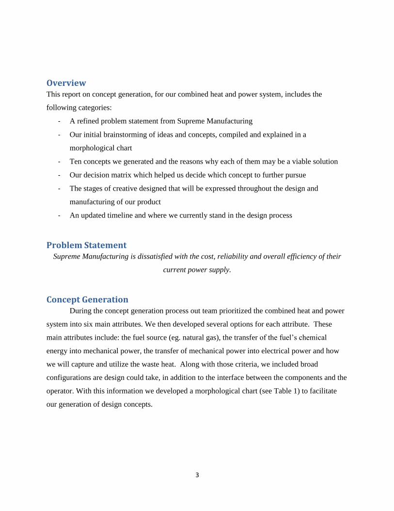
Concept Generation During the concept generation process out team prioritized the combined heat and power
system into six main attributes. We then developed several options for each attribute. These
main attributes include: the fuel source (eg. natural gas), the transfer of the fuel’s chemical
energy into mechanical power, the transfer of mechanical power into electrical power and how
we will capture and utilize the waste heat. Along with those criteria, we included broad
configurations are design could take, in addition to the interface between the components and the
operator. With this information we developed a morphological chart (see Table 1) to facilitate
our generation of design concepts.
4
Attributes Options
Fuel Natural Gas Diesel Propane Solar
Power Generation Sterling Internal Comb. Turbine Fuel Cell
Capture Heat Buffer Tank Compress/Condition
Exhaust Cold Reservoir
Generator/Inverter Purchase
Tailored Design Off-the-Shelf
Frame/Structure Integrated Stand Alone Versatility/Mobility
Programming GUI Switches Gauges
Table 1: Morphological Chart
Concepts
Alternative Fuel Single-Cylinder Stirling Engine (Ryan Christie)
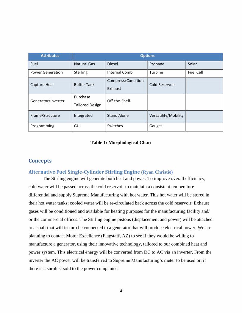
The Stirling engine will generate both heat and power. To improve overall efficiency,
cold water will be passed across the cold reservoir to maintain a consistent temperature
differential and supply Supreme Manufacturing with hot water. This hot water will be stored in
their hot water tanks; cooled water will be re-circulated back across the cold reservoir. Exhaust
gases will be conditioned and available for heating purposes for the manufacturing facility and/
or the commercial offices. The Stirling engine pistons (displacement and power) will be attached
to a shaft that will in-turn be connected to a generator that will produce electrical power. We are
planning to contact Motor Excellence (Flagstaff, AZ) to see if they would be willing to
manufacture a generator, using their innovative technology, tailored to our combined heat and
power system. This electrical energy will be converted from DC to AC via an inverter. From the
inverter the AC power will be transferred to Supreme Manufacturing’s meter to be used or, if
there is a surplus, sold to the power companies.
5
Highlights:
- High efficiency
- Non-invasive
- Low GHG production
- Cost effective
- Steady-state operation
- Highly reliable
Downsides:
- Depending on the type of Stirling engine, there is a potential for low power output
proportional to mass
- May not provide the highest overall efficiency
- Hot water and Heating (heating, aside from for use in ovens) may not be desired,
consistently in Houston
Trigeneration Concept (Ryan Christie) The idea of trigeneration includes using a heat engine to produce electricity, heating and
heating to meet the heat input needs for an absorption refrigeration system. Because Supreme
Manufacturing is located in Houston they will rely on cooling their facility more than heating it.
Therefore, if trigeneration can prove to be economically viable, efficient, reliable and fitting for
this application, it may be the best option for Supreme Manufacturing’s needs.
Highlights:
- Produce electricity and heating for heating the facility and providing (if applicable) heat
input for a absorption refrigeration system
- Effective
- Efficient
Downsides:
- Potentially invasive
- Potentially expensive

6
Waste Heat-Powered Ovens (Nathan Duray) This concept is characterized by the use of waste heat to provide hot air for the
manufacturing ovens. A natural gas fuel source is used to create a hot reservoir for a Stirling
power plant. This power plant produces three outputs: hot air, hot water and electricity. The
electricity will be produced by the mechanical energy produced from the Stirling engine while
the hot air and water will be drawn from the cold reservoir of the same engine. This would mean
the cold reservoir would need to operate at approximately 400k while the hot reservoir is held at
800k. This gives us a relatively low max efficiency, ηCarnot = 50%, for mechanical output to the
electric generator. However, due to the use of waste heat to power the ovens, the need for
electrical power is greatly reduced and much of the overall efficiency value can be recovered.
Residual waste heat can be utilized to create hot water for the commercial facility. Though this
design reduces the water need for cooling, it requires an invasive integration process. The current
electric ovens would need to be adapted to function from an external hot air heat source. Also,
the hot air lines to convey this hot air would need to be installed into the facility—increasing the
cost of the installation for our customer.
Fuel Source
(Natural Gas)
Power Production
(Stirling Engine)
Hot Air
(From Cold Reservoir)
Hot Water Electricity

7
Combine Cycle Generation (Nathan Duray) This concept is characterized by the use of waste heat to power a second power cycle.
Fuel in the form of natural gas will be used to power an internal combustion engine. This
internal combustion engine will produce the mechanical energy to provide electric energy
generation. To boost efficiency, the exhaust gasses from the internal combustion engine will
then be used to produce the hot reservoir for a Stirling engine. This Stirling engine will then
produce additional electric energy which will contribute to the total electric output. Residual
thermal energy can then be absorbed through the cold reservoir of the Stirling engine to produce
hot water for the commercial facility.
Fuel Source
(Natural Gas)
Internal
Combustion Engine
Exhaust Gases
Electric Power
Sterling Engine Electric Power
Hot Water

8
Horizontally Opposed “Boxer” Stirling Engine (Joseph Mudd) By combining two beta-type Stirling Engines out of phase, a large flywheel is no longer
needed. This is important to cut costs, weight, and complexity. This design also reduces
vibration, increases power output, and makes a smoother, more reliable design.
Figure 1: Horizontally Opposed Stirling Engines
Fuel Cells (Cory Donavon)
Background:
- Uses fuels to convert hydrogen and oxygen into water, creating electricity in the
process.
- No pollution, because the only by-products are heat and water.
- Can run on fuels such as: methane, gasoline, and hydrogen. Hydrogen works the
best.
- Converts chemical energy and produces electrical energy.
- Durable; good for cyclic/transient loading

9
- Is flexible in terms of fuels
- Some fuel cells generate a lot of heat, which can be captured and used to do work
o These fuel cells consist primarily of molten carbonate fuel cells (MCFC),
phosphoric acid fuel cells (PAFC), and solid oxide fuel cells (SOFC).
- Very clean and energy efficient
- Quiet
- Very few moving parts, so integration would be minimally invasive
- Potential for renewable energy – excess heat and power can be used to generate
hydrogen, which can then be reused by the CHP system or can even power a hydrogen
fuel cell vehicle!
Cons/Difficulties:
- Although hydrogen works best, it is difficult to acquire.
- Costly
- Needs to be more efficient in order to be competitive with other methods in cost
Six Stroke Engine (Cory Donavon)
Background:
- Traditional four-stroke engines have one stroke dedicated to powering the vehicle or
device. The six stroke engine adds an additional power stroke in order to greatly increase
efficiency.
- Once the exhaust cycles out of the chamber, rather than introducing more fuel right away,
water is instead injected. Upon doing this, the heat of the chamber expands the water to
1600 times it original volume, creating enough pressure that forces the piston down
again.
o This water injection also allows cooling of the engine, rendering the heavy
radiator, coolant, and fans useless.
- Allows the engine to be more efficient – using less fuel – yet delivers just as much power
as standard ICEs. All friction losses to the fan and radiator are gone, since the extra
components are not necessary anymore.

10
Cons/Difficulties
- Concept still in its infancy. There are still a lot of bugs to be worked out, including:
o Needing distilled water so no residue forms inside chambers
o Water freezing (unlikely in Houston, Texas, but still noteworthy)
Organic Rankine Power Cycle (Jason Dikes) This concept is based on using an Organic Rankine power cycle to turn waste heat into
electricity. The term organic comes from the use of an organic material, with a high molecular
mass, as the working fluid of the system. The boiling point of the organic material is lower than
that of water and therefore the system does not require as much heat to produce electricity when
compared to a normal Rankine cycle. This is a proven concept in industry and offers great
reliability. Additionally, alternative fuels can be used to power the system.
The system would also use a Gerotor instead of a turbine. The Gerotor is cheaper to
produce and creates very little friction. The reduction in friction means that the working fluid can
exert less force to generate electricity. This will also lower the temperature needed to power the
system.
Figure 2: Rankine Cycle

11
Figure 3: Gerotor
Shape Memory Alloy (Jason Dikes) One design concept is possibly using a shape memory alloy (SMA) heat engine to turn waste heat
into usable electricity. There are a lot of small scale SMA heat engines on the market currently, with a
wide range of designs. Our job for the capstone project would be either taking one of these small scale
designs and scaling it up for an industrial application or coming up with our own original design that will
meet our client’s needs. One major consideration for this design concept would be the price of SMA. The
price can vary anywhere from $10 per kilogram to $200 per kilogram. One possible design is shown
below.
Figure 4: Shape Memory Alloy

12
Quasiturbine Engine (Ronald Stepanek) For our combined heat and power system we have considered many different options for
engines to power a generator. One of these options is the Quasiturbine engine. There have been
several instances in which the Quasiturbine engine has been considered as an alternative to a
standard type Stirling Engine design. This engine design has shown potential as an internal
combustion type engine, as well as a steam powered engine and pneumatic engine. There are
already Quasiturbine engines in production that utilize steam and pneumatic capabilities to
produce up to 12 kW of power from a single engine.
Production units that produce 12 kW while utilizing steam or compressed air are readily
available for $8900 per unit. The capabilities of these units are dependent on the pressures at
which they operate. The 12 kW model requires a pressure of 4 bar.
In order to integrate a Quasiturbine engine into our design we must first find a way to
create pressures upwards of 4 bar. Potential ideas for this include using waste heat from the
ovens to aid in steam generation, using compressed air from a holding tank, or perhaps using the
Quasiturbine engine in conjunction with another engine type that produces high pressure
differentials or waste heat.
Figure 5: Quasiturbine schematic

13
Weighting Factor Tree
this space intentionally left blank
Combined Heat and
Power System
K = 1.0 w = 1.0
Cost
K = 0.15 w
= 0.15
Geometry
K = 0.1 w = 0.1
Efficiency
K = 0.2 w = 0.2
Power Output
K = 0.2 w = 0.2
Reliability
K = 0.35 w = 0.35
Initial Cost
K = 0.2 w = 0.03
Operating Cost
K = 0.3 w = 0.045
Rate of Return
K = 0.5 w = 0.075
Volume
K = 0.3 w = 0.03
Integration
K = 0.7 w = 0.07
Energy Efficiency
K = 0.8 w = 0.16
Alternative Energy
K = 0.2 w = 0.04
Water
K = 0.1 w = 0.02
Use Life
K = 0.3 w = 0.105
On Demand Power
Production
K = 0.7 w = 0.245
Electricity
K = 0.8 w = 0.16
Heating
K = 0.1 w = 0.02

14
Decision Matrix and Concept Selection Shown below is the decision matrix we implemented to help us determine the best concept.
Table 2: Decision Matrix
In this decision matrix we compare six of our most likely generated concepts against our
five primary weighted criteria from the weighting factor tree. As is clearly seen, our Internal
Combustion Engine (ICE) plus Heat Recovery system scored highest in both the weighted and
non-weighted totals, distinguishing it as our most viable option thus far. The ICE + Heat
Recovery system attained scores that matched or exceeded all other scores in three of the five
categories for evaluation. One may note that while the ICE + Heat Recovery tied the Beta-type
Stirling Engine in reliability, the low scores under power output for the Beta-type Stirling make
the ICE + Heat recovery a much better option. Again, while the Rankine Cycle received the same
score for power output as the ICE + Heat recovery system, the Rankine Cycle’s low scores in
cost and geometry further solidify our decision. Lastly, it is worth noting the effects of the
weights of the criteria. Despite being assigned equal non-weighted totals, the 6-stroke ICE, Beta-
type Stirling Engine, and Horizontally opposed Stirling Engines differ significantly in their
weighted totals column.
Cost (15%) Geometry (10%) Efficiency (20%) Reliability (35%) Power Output (20%) TotalsWeighted
Totals
ICE + Heat Recovery 4 3 3 5 4 19 4.05
6-Stroke I.C.E 2 4 3 3 3 15 2.95
Trigeneration 2 1 4 2 3 12 2.5
Rankine Cycle 1 1 2 4 4 12 2.85
Beta-type
Stirling Engine3 3 3 5 1 15 3.3
Horizontally Opposed
Stirling Engines3 3 3 4 2 15 3.15

15
Creative Design
Selection Design
- Alternative Fuel, Internal Combustion Engine and Electricity Generator
Configuration Design
- Ancillary Engine and/ or Heat Recovery System
Parameter Design
- Engine Displacement and Geometry of System
Original Design
- Control System/ Graphical User Interface (GUI), Frame and Substructure, Heat Recovery
System, Shaft from engine to generator

16
Timeline
17
Appendix
Table 1
4
Table 2
14
Figure 1
8
Figure 2
10
Figure 3
11
Figure 4
11
Figure 5
12