Embed Size (px)
Citation preview
Int. J. Vehicle Design, Vol. 59, No. 4, 2012 315
Combined design and robust control of a vehicle
passive/active suspension
S.F. Alyaqout*, P.Y. Papalambros
and A. Galip Ulsoy
Department of Mechanical Engineering,College of Engineering and Petroleum,Kuwait University P.O. Box: 5969,Safat 13060, KuwaitE-mail: [email protected]: [email protected]: [email protected]∗Corresponding author
Abstract: An approach that combines passive and active elements toimprove the robustness of a vehicle suspension system with respect toa worst-case scenario is introduced, and leads to a coupled optimisationproblem that is often difficult to solve. A sequential strategy that dependson the strength of coupling and optimises the passive elements first,and then the active elements, reduces computational effort. Varying suchparameters as level of uncertainty, tyre stiffness, and unsprung massparameters leads to a relationship between coupling and robustness of thecontrol. Results show that coupling between design and robust controlincreases as uncertainty increases.
Keywords: coupling; design; robust control; combined design and control.
Reference to this paper should be made as follows: Alyaqout, S.F.,Papalambros, P.Y. and Ulsoy, A.G. (2012) ‘Combined design and robustcontrol of a vehicle passive/active suspension’, Int. J. Vehicle Design,Vol. 59, No. 4, pp.315–330.
Biographical notes: Sulaiman F. Alyaqout received his PhD in MechanicalEngineering from the The University of Michigan, Ann Arbor. He isan Assistant Professor in the Department of Mechanical Engineering,Kuwait University, Kuwait. His research interests include robust design,robust control, combined design and control, optimisation, automotivecontrol systems.
Panos Y. Papalambros is the Donald C. Graham Professor ofEngineering and a Professor of Mechanical Engineering at the Universityof Michigan. He is also Professor of Architecture and Professor ofArt and Design. He received his PhD in Mechanical Engineering fromStanford University (1979). His research interests include design scienceand optimisation, with applications to product design and development,automotive systems, such as hybrid and electric vehicles, and architecturaldesign.
Copyright © 2012 Inderscience Enterprises Ltd.

316 S.F. Alyaqout et al.
A. Galip Ulsoy is the William Clay Ford Professor of Manufacturingat The University of Michigan, Ann Arbor. He received his PhDin Mechanical Engineering from the University of California atBerkeley (1979). His research interests include control system design,manufacturing systems, automotive systems.
1 Introduction
The design of vehicle suspension systems is influenced by several conflictingperformance requirements. Such requirements include isolating passengers from roaddisturbances to improve ride comfort and maintaining good road holding to improvevehicle handling. For optimisation problems, these requirements are often representedby a weighted performance function (Hrovat, 1993, 1997). Active suspensions canbetter resolve the tradeoffs among these conflicting performance requirements becausethey have the ability to not only store and dissipate, but also to introduce energyinto the system. As a result, active suspensions outperform passive suspensions(Hrovat, 1997; Fathy et al., 2003; Smith and Walker, 2000). On the other hand, activesuspensions require suitable actuator devices and high levels of energy-consumptionleading to an increase in system costs. To reduce such costs, and to ensure ‘limp-home;performance in case of active suspension failure, it is desirable to combine passive andactive elements in a suspension.
Another critical requirement for active suspension design is to improve therobustness of the suspension system.Many active suspension control approaches havebeen proposed, utilising various modern control techniques, such as Linear-Quadratic(LQ) (Ulsoy et al., 1994), Linear-Quadratic-Gaussian (LQG) (Ulsoy et al., 1994;Ulsoy and Hrovat, 1990), adaptive control (Chantranuwathana and Peng, 2004),and nonlinear control (Fialho and Balas, 2000). However, in practice the total massof the vehicle is uncertain due to changes in passenger and cargo loads, and thedamping of the vehicle is uncertain due to approximating the nonlinear model with alinear one, etc. As a result, robust control synthesis for active suspension systems hasbeen investigated by several researchers (Lauwerys et al., 2005; Ray, 1992). Recently,several authors employedH∞-based control to improve the robustness properties anddisturbance attenuation of active suspensions (Chen and Kong-Hui, 2005; Hayakawaet al., 1999).
The problem with H∞-based controllers is that they are typically tooconservative (Petersen et al., 2000).
Several authors have examined strength-based coupling between design andcontrol optimisation problems (Onoda and Haftka, 1987; O’Neal et al., 2001;Alyaqout et al., 2006). Alyaqout et al. (2005, 2007), Reyer et al. (2001), andFathy et al. (2001) proposed the use of optimality conditions to characterisecoupling. In Alyaqout et al. (2007), we defined coupling relative to the solutionmethod, by comparing the optimality conditions of a sequential design and robustcontrol solution strategy with the optimality conditions of the undecomposedsystem optimisation problem. Hence, this coupling was shown to have adirect effect on determining the system optimum. In addition, we related
Combined design and robust control of a vehicle suspension 317
coupling between design and robust control to the robustness of the controlsystem.
Much of the research in modern control of active suspensions has been concernedwith robust control. Robust control assumes that the passive design variablesare parameters that should not be modified during the controller design process.Therefore, the effect of the passive design variables in improving the robustness of thecontrol system is ignored. In addition, most previous characterisations of coupling failto incorporate uncertainty. By incorporating this uncertainty, Alyaqout et al. (2007)introduced an original relationship between coupling and robustness, which is appliedhere to the vehicle suspension system case study.
In the present article the design and robust control of a vehicle passive/activesuspension system is examined via the relationship between coupling and robustnessresulting from varying different suspension parameters. Section 2 presents thetwo degree-of-freedom quarter-car vehicle suspension model used for the study.Section 3 poses the system problem under consideration. In Section 4, we studythe relationship between coupling and robustness. In Section 5, we examine thefrequency response of the suspension. The article concludes with a discussion ofresults and future work.
2 Vehicle suspension model
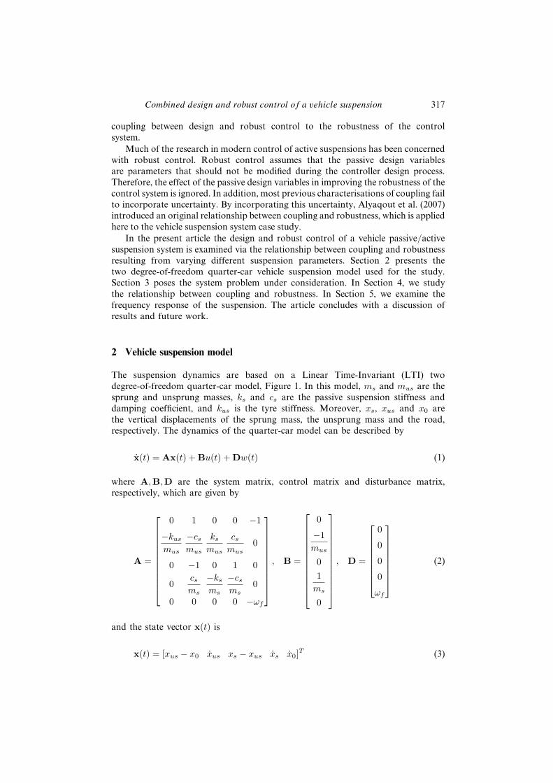
The suspension dynamics are based on a Linear Time-Invariant (LTI) twodegree-of-freedom quarter-car model, Figure 1. In this model, ms and mus are thesprung and unsprung masses, ks and cs are the passive suspension stiffness anddamping coefficient, and kus is the tyre stiffness. Moreover, xs, xus and x0 arethe vertical displacements of the sprung mass, the unsprung mass and the road,respectively. The dynamics of the quarter-car model can be described by
x(t) = Ax(t) + Bu(t) + Dw(t) (1)
where A,B,D are the system matrix, control matrix and disturbance matrix,respectively, which are given by
A =
0 1 0 0 −1
−kus
mus
−cs
mus
ks
mus
cs
mus0
0 −1 0 1 0
0cs
ms
−ks
ms
−cs
ms0
0 0 0 0 −ωf
, B =
0
−1mus
01
ms
0
, D =
0
0
0
0
ωf
(2)
and the state vector x(t) is
x(t) = [xus − x0 xus xs − xus xs x0]T (3)
318 S.F. Alyaqout et al.
Figure 1 Quarter-car model for an active suspension system
where xs − xus is the suspension stroke, xus − x0 is the tyre deflection andu(t) is the scalar active force generated by an actuator. The ground motionw(t) = x0(t) is a hypothetical zero-mean, white and Gaussian disturbance ofvariance 2πA0V , where A0 is a ground motion amplitude scaling factor and V is thevehicle forward velocity (Ulsoy et al., 1994). In addition, this ground motion w(t)is acted upon by a first-order low-pass filter with cutoff frequency ωf = 20.91 toproduce a coloured ground disturbance velocity input (Fathy et al., 2003). Finally,we assume that all system states are available for feedback, therefore no observeris required.
3 The DRC vehicle suspension problem
We now present a combined robust passive/active suspension problem writtenin the form of the Design and Robust Control (DRC) formulation introducedby Alyaqout et al. (2007). The design determines the passive suspension stiffnessks and damping coefficient cs, while the control determines the full state feedbackcontroller gains. The objective is to improve performance robustness of a weightedsum of sprung mass acceleration, wheel hop, rattle space, and control effort whilemaintaining robust stability assuming uncertainty in the sprung mass ms. Giventhe system dynamics in equation (1), consider the following active suspension DRCoptimisation problem
minks,cs,x(t),u(t),K
max∆ms
F
= E
( ∫ tf
ti
(r0x2s + r1(xus − x0)2 + r2(xs − xus)2 + r3u
2)dt
)subject to

Combined design and robust control of a vehicle suspension 319
x(t)=
0 1 0 0 −1
−kus
mus
−cs
mus
ks
mus
cs
mus0
0 −1 0 1 0
0cs
ms
−ks
ms
−cs
ms0
0 0 0 0 −ωf
x(t)+
0 0
−1mus
0
0 01
ms0
0 ωf
[u(t)
w(t)
]
ks ≤ 160000 , cs ≤ 16000 (4)
1 − α ≤ ∆ms ≤ 1 + α, u(t) = −Kx(t)
(ks, cs,x(t), u(t),K, ∆ms) ∈ {(ks, cs,x(t), u(t),K, ∆ms) : eig(A − BK) ≤ 0,
for every ∆ms ∈ {∆ms : 1 − α ≤ ∆ms ≤ 1 + α}}
where
ms = (ms)(∆ms), E(w(t)w(τ)) = 2πA0V δ(t − τ).
Here ∆ms is the real set-based uncertainty in the sprung mass ms ∈ R withresulting variable ms ∈ R defined to represent percentage type uncertainty, F is theperformance index, E(·) is the expected value operator, eig (·) is the eigen value of amatrix, δ is the Dirac delta function, and α is the level of uncertainty. The quantitiesr0, r1, r2 and r3 are parameters that weigh the sum of root mean square valuesof sprung mass acceleration x4rms, tyre deflection (wheel hop) x1rms, suspensionstroke (rattle space) x3rms and active control force (Ulsoy et al., 1994), respectively.In addition, full state feedback is assumed and K ∈ R
1×5 is the correspondingcontroller gain.
There are several challenges associated with solving the DRC optimisationproblem. The solution of this minimax optimisation problem requires heavycomputational effort even for modestly-sized problems, since the number of designvariables under uncertainty increases the complexity of the optimisation problem.In addition, the DRC can be a non-convex optimisation problem even if theindividual design and robust control optimisation problems are convex.
Some of the problems associated with solving the DRC optimisation problemcan be avoided by utilising a sequential strategy under uncertainty that often yieldsa suboptimal solution (i.e., improved solution but not optimal). Now we introducesuch a Sequential Design and Robust Control (SDRC) strategy (Alyaqout et al.,2007) to solve the DRC active suspension problem in equation (4). The SDRCstrategy optimises the design problem first. Then the design solution is used in theoptimisation of the robust control problem, thus saving time and cost. The designproblem can be described as follows
minks,cs
E
( ∫ tf
ti
(r0x2s + r1(xus − x0)2 + r2(xs − xus)2)dt
)subject to (5)
ks ≤ 160000, cs ≤ 16000

320 S.F. Alyaqout et al.
where
x(t) = Ax(t) + Dw(t), E(w(t)w(τ)) = 2πA0V δ(t − τ).
The design problem in equation (5) has no dependence on the control variablesand parameters. This makes the problem easier to solve and removes the need foriteration between the design and robust control optimisation problems.
After solving the design problem in equation (5), the resulting optimal solutionis used to solve the following robust control problem
J(xd) = minx(t),u(t),K
max∆ms
×E
( ∫ tf
ti
(r0x2s + r1(xus − x0)2 + r2(xs − xus)2 + r3u
2)dt
)subject to
x(t) =
0 1 0 0 −1
−kus
mus
−cs
mus
ks
mus
cs
mus0
0 −1 0 1 0
0cs
ms
−ks
ms
−cs
ms0
0 0 0 0 −ωf
x(t) +
0 0−1mus
0
0 01
ms0
0 ωf
[u(t)
w(t)
]
1 − α ≤ ∆ms ≤ 1 + α, u(t) = −Kx(t) (6)
(ks, cs,x(t), u(t),K, ∆ms)
∈{(ks, cs,x(t), u(t),K, ∆ms) : eig(A − BK) ≤ 0,
for every ∆ms ∈ {∆ms : 1 − α ≤ ∆ms ≤ 1 + α}}
where
ms = (ms)(∆ms), E(w(t)w(τ)) = 2πA0V δ(t − τ).
The robust control problem in equation (6) is affected by the design variablesks, cs and uncertainty associated with design parameter ms = 2000 kg. However,note that the values of ks and cs are fixed in equation (6). Since the robustsuspension problem in equation (4) is written in terms of the DRC notation, thenthe DRC coupling ΓR for the active suspension problem can be calculated asfollows (Alyaqout et al., 2007).
ΓR =∣∣∣∣∣∣∣∣ ∂J
∂xd
∣∣∣∣∣∣∣∣2
(7)
where xd = (ks, cs)T is the vector of design variables, ||.|| is the vector norm,J is the performance index as defined in equation (6). Thus, ΓR reflects the
Combined design and robust control of a vehicle suspension 321
sensitivity of the objective function at the optimum to the values of the designvariables ks, cs.
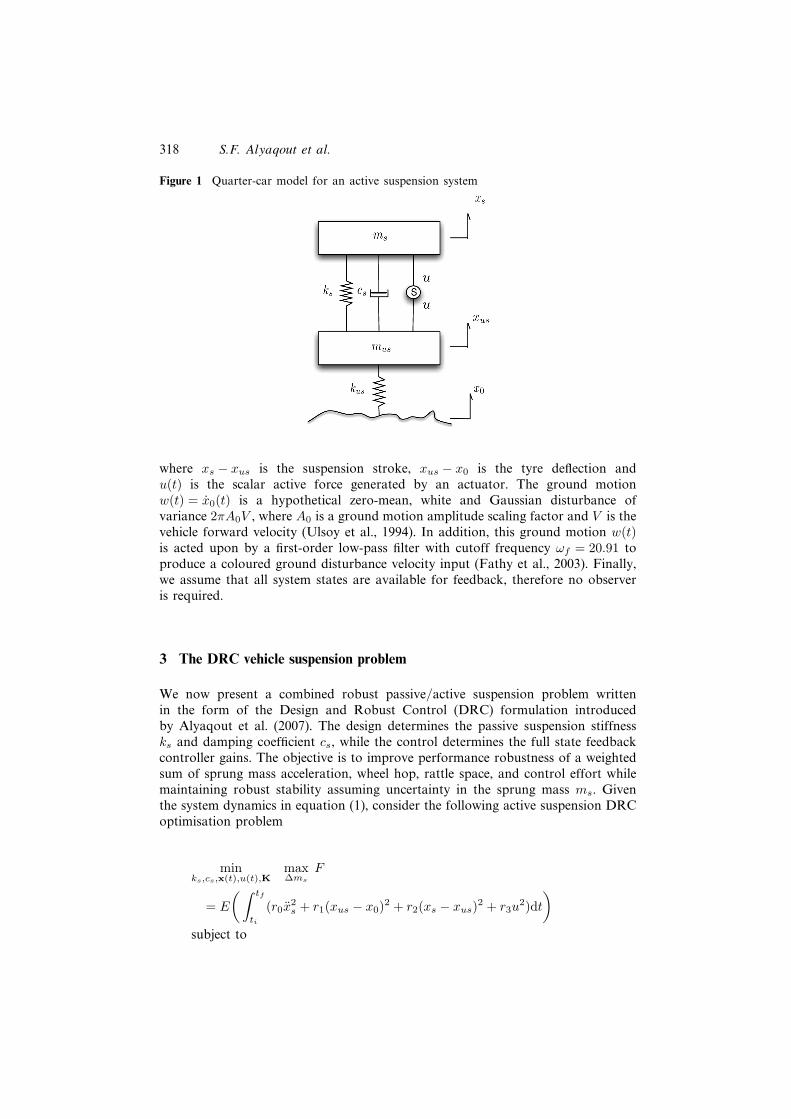
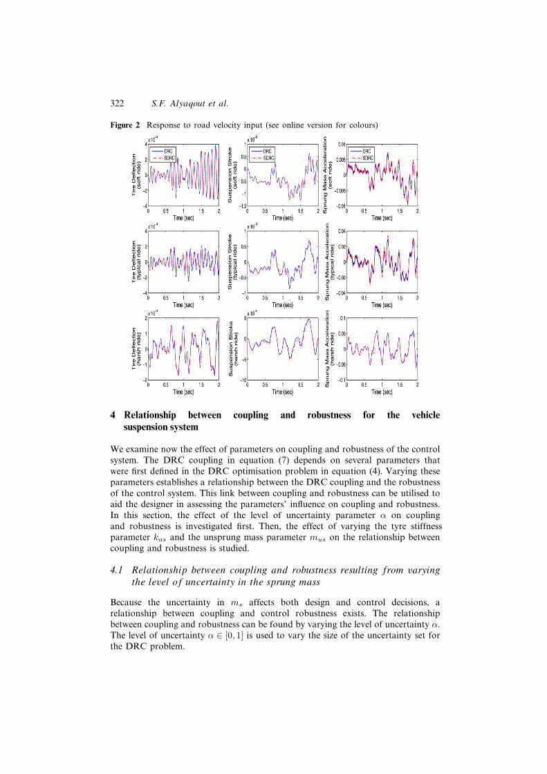
A comparison of active DRC suspensions with various ride characteristics forthe nominal zero uncertainty case (α = 0) is presented in Table 1. An unsprungmass of mus = 200 kg and a tyre stiffness of kus = 790 kN/m were used toproduce the results shown in Table 1. The selection of the weighting parametersr0, r1, r2 and r3 in the performance index F allows one to achieve thesedifferent ride characteristics (Hrovat, 1993). Following Ulsoy et al. (1994), threeride characteristics are compared: the soft ride case (S) is found with r0 = 1,r1 = 1, r2 = 6, r3 = 4 × 10⁻⁹; the typical ride case (T) with r0 = 1, r1 = 1,r2 = 2 × 10³, r3 = 4 × 10⁻⁸; and the harsh ride case (H) with r0 = 1, r1 = 3 × 10⁴,r2 = 3 × 10⁴, r3 = 4 × 10⁻⁶. The soft ride (DRC/S) is characterised by a low sprungmass rms acceleration of 3.16, a large rms suspension stroke of 0.5921, and alarge rms tyre deflection of 0.1962. The harsh ride (DRC/H) case provides a lowsuspension stroke of 0.208 and a tyre deflection of 0.0655, but at the expense of ahigh sprung mass rms acceleration of 22.66. The typical ride (DRC/T) case has amedium sprung mass acceleration of 10.57, a suspension stroke of 0.319, and a tyredeflection of 0.076 compared to the soft and harsh ride cases. The correspondingSDRC suspensions are also shown in Table 1. Figure 2 shows the response toroad velocity input for the case shown in Table 1, assuming unity disturbancevariance (2πA0V = 1).
Table 1 Active DRC and SDRC Suspensions With Various Ride Characteristics for theNominal Zero Uncertainty Case (S = soft ride, T = typical ride, andH = harsh ride)
DRC/S DRC/T DRC/H SDRC/S SDRC/T SDRC/H
Performance index 31.15 321.97 1991.9 32.43 335.8 2039.8
x1rms/√
2πA0V 0.1962 0.076 0.0655 0.1676 0.06 0.066
x3rms/√
2πA0V 0.5921 0.319 0.208 0.582 0.3098 0.2125
x4rms/√
2πA0V 3.16 10.57 22.66 3.311 11.502 22.438
ks (kN/m) 1.66 18.5 31.7 1.2 1.2 2.44
cs(kN.s/m) 0.312 3.05 16.0 1.89 7.95 16.0
Controller
gain, K(103) 13.88 63.2 4.92 13.93 55.4 11.72
0.06 1.33 0.41 1.55 4.747 0.405
13.7 64.7 57.7 14.17 81.85 81.6
7.46 14.2 5.85 5.88 9.85 7.73
−0.49 −2.12 −0.299 −0.425 −1.369 −0.572
322 S.F. Alyaqout et al.
Figure 2 Response to road velocity input (see online version for colours)
4 Relationship between coupling and robustness for the vehiclesuspension system
We examine now the effect of parameters on coupling and robustness of the controlsystem. The DRC coupling in equation (7) depends on several parameters thatwere first defined in the DRC optimisation problem in equation (4). Varying theseparameters establishes a relationship between the DRC coupling and the robustnessof the control system. This link between coupling and robustness can be utilised toaid the designer in assessing the parameters’ influence on coupling and robustness.In this section, the effect of the level of uncertainty parameter α on couplingand robustness is investigated first. Then, the effect of varying the tyre stiffnessparameter kus and the unsprung mass parameter mus on the relationship betweencoupling and robustness is studied.
4.1 Relationship between coupling and robustness resulting from varyingthe level of uncertainty in the sprung mass
Because the uncertainty in ms affects both design and control decisions, arelationship between coupling and control robustness exists. The relationshipbetween coupling and robustness can be found by varying the level of uncertainty α.The level of uncertainty α ∈ [0, 1] is used to vary the size of the uncertainty set forthe DRC problem.
Combined design and robust control of a vehicle suspension 323
The DRC coupling defined in equation (7) can be interpreted as a measureof the degree to which the SDRC solution can achieve the DRC solution.The importance of the DRC coupling stems from the direct effect it has on thelocation of the DRC robust system solution.
Alternatively, another measure of coupling can be defined by comparing theoptimal worst-case performance of the DRC problem with the optimal worst-case performance of the SDRC problem. Let F ∗
SDRC represent the optimal worst-case objective obtained using the SDRC strategy, and F ∗
DRC represent the optimalworst-case objective obtained using the DRC strategy. Then the coupling strengthmeasure can be defined as the absolute difference between the optimal worst-caseperformances of the SDRC and DRC strategies |F ∗
DRC − F ∗SDRC|.
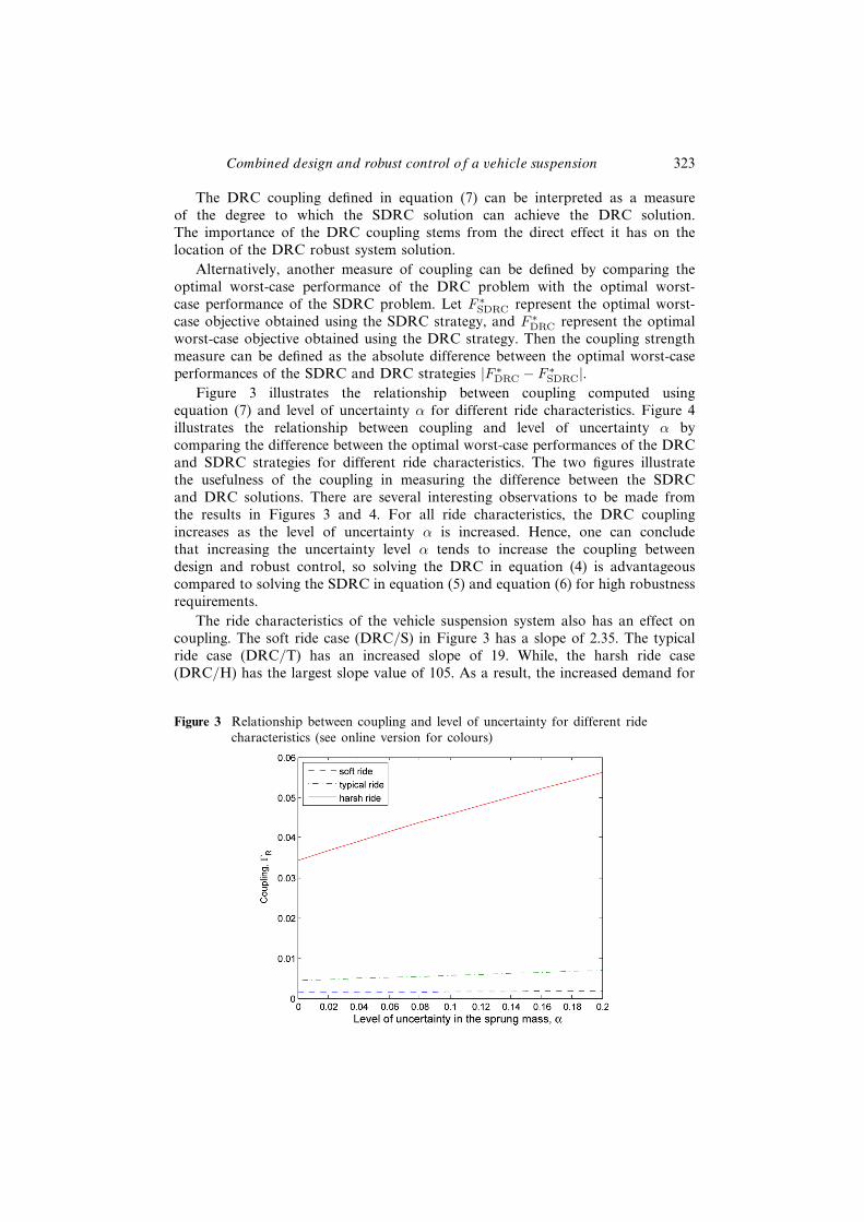
Figure 3 illustrates the relationship between coupling computed usingequation (7) and level of uncertainty α for different ride characteristics. Figure 4illustrates the relationship between coupling and level of uncertainty α bycomparing the difference between the optimal worst-case performances of the DRCand SDRC strategies for different ride characteristics. The two figures illustratethe usefulness of the coupling in measuring the difference between the SDRCand DRC solutions. There are several interesting observations to be made fromthe results in Figures 3 and 4. For all ride characteristics, the DRC couplingincreases as the level of uncertainty α is increased. Hence, one can concludethat increasing the uncertainty level α tends to increase the coupling betweendesign and robust control, so solving the DRC in equation (4) is advantageouscompared to solving the SDRC in equation (5) and equation (6) for high robustnessrequirements.
The ride characteristics of the vehicle suspension system also has an effect oncoupling. The soft ride case (DRC/S) in Figure 3 has a slope of 2.35. The typicalride case (DRC/T) has an increased slope of 19. While, the harsh ride case(DRC/H) has the largest slope value of 105. As a result, the increased demand for
Figure 3 Relationship between coupling and level of uncertainty for different ridecharacteristics (see online version for colours)

324 S.F. Alyaqout et al.
Figure 4 Relationship between the absolute difference of DRC and SDRC optimalworst-case performances and level of uncertainty for different ride characteristics(see online version for colours)
robustness for vehicle suspensions with harsh ride characteristics tend to increasecoupling even further, so solving the DRC in equation (4) is advantageous for highrobustness requirements for the harsh ride case (DRC/H). On the other hand, theincreased demand for robustness in vehicle suspensions with soft ride characteristicstends to increase coupling slightly with much lower slope than with typicaland harsh ride characteristics. Hence, decoupled vehicle suspensions with softride characteristics tend to remain decoupled even with increased demand forrobustness.
In summary, coupling between design and robust control tends to increasewith the level of uncertainty applied. In addition, decoupled vehicle suspensionswith soft ride characteristics tend to remain decoupled even with increased demandfor robustness, while demanding more robustness for vehicle suspensions with harshride characteristics increases coupling much more rapidly compared to suspensionswith soft and typical ride characteristics.
4.2 Relationship between coupling and robustness resulting from varyingthe tyre stiffness and unsprung mass parameters
The relationship between coupling and robustness can also be examined by varyinga suspension system parameter. By fixing the level of uncertainty of the sprung massα, the parameter value effect on coupling and robustness can be examined. Here,we investigate the effect of tyre stiffness kus and unsprung mass mus on couplingand robustness. To that end, we assume that the level of uncertainty α is fixed atα = 0.2 (i.e., 20% uncertainty). Moreover, let us consider the typical case (DRC/T)ride characteristic.

Combined design and robust control of a vehicle suspension 325
Following Alyaqout et al. (2007), we first define our notion of control systemrobustness. Consider the following definition for worst-case control performanceF ∗
DRC obtained using the DRC strategy. Then control system robustness is definedas the reciprocal 1/F ∗
DRC. Note that decreasing F ∗DRC increases robustness. Hence,
this definition is consistent because increasing 1/F ∗DRC increases robustness and
vice-versa. Now we examine the relationship between the DRC coupling and therobustness of the control system.
Consider varying the tyre stiffness kus from 520 kN/m to 1600 kN/m.The relationship between coupling and robustness, obtained by varying the tyrestiffness kus, is illustrated in Figure 5. The DRC coupling has a monotonicallyincreasing relationship with robustness, so decreasing coupling decreases robustness.Hence, there is a tradeoff between coupling and robustness. In this tradeoff,decreasing the tyre stiffness kus tends to decrease coupling at the cost of decreasedrobustness, while increasing kus tends to increase robustness at the cost of increasedcoupling. Therefore, vehicle suspension systems with large tyre stiffness tend to haveimproved robustness and large coupling, while suspension systems with small tyrestiffness kus tend to have small coupling and reduced robustness.
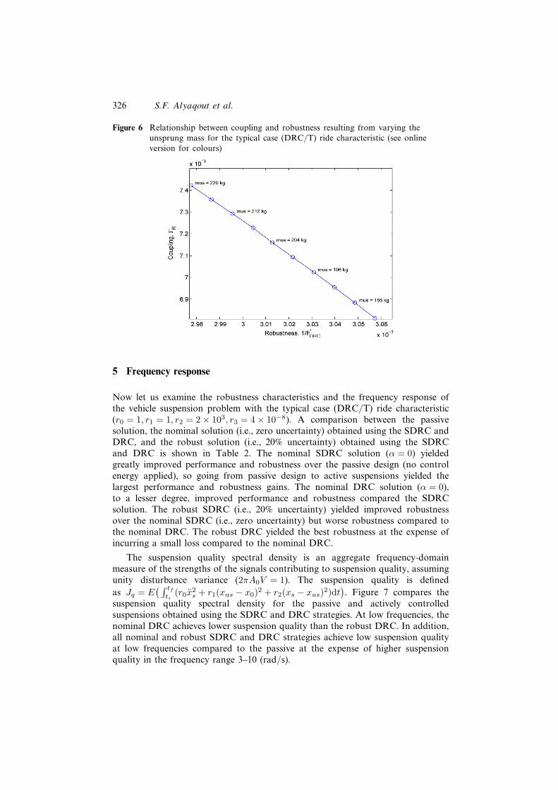
Now consider varying the unsprung mass mus from 184 kg to 220 kg. Figure 6shows the relationship between coupling and robustness obtained by varyingthe unsprung mass mus. The DRC coupling has a monotonically decreasingrelationship with robustness, so decreasing coupling increases robustness. Therefore,reducing the unsprung mass mus improves both coupling and robustness whileincreasing the unsprung mass mus increases coupling and reduces robustness.Therefore, vehicle suspension systems with small unsprung mass tend to haveimproved robustness and smaller coupling.
Figure 5 Relationship between coupling and robustness resulting from varying the tyrestiffness for the typical case (DRC/T) ride characteristic (see online versionfor colours)
326 S.F. Alyaqout et al.
Figure 6 Relationship between coupling and robustness resulting from varying theunsprung mass for the typical case (DRC/T) ride characteristic (see onlineversion for colours)
5 Frequency response
Now let us examine the robustness characteristics and the frequency response ofthe vehicle suspension problem with the typical case (DRC/T) ride characteristic(r0 = 1, r1 = 1, r2 = 2 × 10³, r3 = 4 × 10⁻⁸). A comparison between the passivesolution, the nominal solution (i.e., zero uncertainty) obtained using the SDRC andDRC, and the robust solution (i.e., 20% uncertainty) obtained using the SDRCand DRC is shown in Table 2. The nominal SDRC solution (α = 0) yieldedgreatly improved performance and robustness over the passive design (no controlenergy applied), so going from passive design to active suspensions yielded thelargest performance and robustness gains. The nominal DRC solution (α = 0),to a lesser degree, improved performance and robustness compared the SDRCsolution. The robust SDRC (i.e., 20% uncertainty) yielded improved robustnessover the nominal SDRC (i.e., zero uncertainty) but worse robustness compared tothe nominal DRC. The robust DRC yielded the best robustness at the expense ofincurring a small loss compared to the nominal DRC.
The suspension quality spectral density is an aggregate frequency-domainmeasure of the strengths of the signals contributing to suspension quality, assumingunity disturbance variance (2πA0V = 1). The suspension quality is definedas Jq = E
( ∫ tf
ti(r0x
2s + r1(xus − x0)2 + r2(xs − xus)2)dt
). Figure 7 compares the
suspension quality spectral density for the passive and actively controlledsuspensions obtained using the SDRC and DRC strategies. At low frequencies, thenominal DRC achieves lower suspension quality than the robust DRC. In addition,all nominal and robust SDRC and DRC strategies achieve low suspension qualityat low frequencies compared to the passive at the expense of higher suspensionquality in the frequency range 3–10 (rad/s).

Combined design and robust control of a vehicle suspension 327
Table 2 Performance and robustness comparison for the Typical Ride Case (DRC/T)
SDRC DRC SDRC DRCDescription Passive α = 0 α = 0 α = 20 α = 20
Susp. performance, F 401.69 335.8 321.97 342.3 324.79
Susp. quality, Jq 401.69 324.22 315.81 323.7 318.32
Control energy, Ju (108) 0 2.894 1.5403 4.6353 1.6169
Worst Performance 446.2 360.69 334.58 353.89 329.43
Worst Susp. quality 446.2 349.88 329.7 336.22 324.47
Worst Control energy 0 2.703 1.222 4.4192 1.2403
ks (kN/m) 1.204 1.204 18.55 1.204 16.86
cs (kN.s/m) 7.953 7.953 3.045 7.953 2.17
Controller gain, K 0 55.4 63.15 45.69 63.17
0 4.75 1.33 5.32 0.925
0 81.8 64.78 66.95 63.83
0 9.849 14.2 6.57 14.27
0 −1.369 −2.12 −1.048 −1.76
Figure 7 Suspension quality spectral density (see online version for colours)
The control energy spectral density is a frequency-domain measure of thecontrol energy (Ju = E
( ∫ tf
tiu2dt
)), assuming unity disturbance variance. Figure 8
shows the control energy spectral density for the passive and actively controlledsuspensions. At low frequencies, the nominal and robust DRC’s seem to consumemuch more energy than the nominal and robust SDRC’s, so much of the nominaland robust DRC’s low energy consumption is concentrated in the frequency range

328 S.F. Alyaqout et al.
Figure 8 Control input spectral density (see online version for colours)
1–100 (rad/s). In addition, the robust DRC and nominal DRC have almostidentical frequency response; similarly, the robust SDRC and nominal SDRC haveidentical response at low frequencies.
6 Conclusion
This article introduced a worst-case approach that combined passive and activeelements to improve the robustness of a vehicle suspension system. This is achievedby examining the relationship between coupling and robustness resulting fromvarying different suspension parameters. This link between coupling and robustnessis utilised in assessing the parameters’ influence on coupling and robustness.
By varying the level of uncertainty parameter, we showed that the couplingbetween design and robust control tended to increase as the applied level ofuncertainty increased. Therefore, designers of active/passive suspensions whodemand more robustness should consider solving the DRC because the SDRCwill not necessarily improve robustness due to the coupling increase. In addition,decoupled vehicle suspensions with soft ride characteristics tend to remaindecoupled even with increased demand for robustness, while demanding morerobustness for vehicle suspensions with harsh ride characteristics increasedcoupling much more rapidly compared to suspensions with soft and typical ridecharacteristics.
We then examined the effect of tyre stiffness kus and unsprung mass mus oncoupling and robustness. For the tyre stiffness, vehicle suspension systems withlarge tyre stiffness tend to have improved robustness but large coupling, whilesuspension systems with small tyre stiffness kus tend to have small coupling butreduced robustness. As for the unsprung mass, vehicle suspension systems withsmall unsprung mass mus tend to have both improved robustness and smallercoupling.
Combined design and robust control of a vehicle suspension 329
Future work should consider including uncertainties in variables and parametersother than the sprung mass ms. Future work should also consider optimisingcoupling to improve robustness as opposed to solving the DRC optimisationproblem.
References
Alyaqout, S.F., Papalambros, P.Y. and Ulsoy, A.G. (2005) ‘Quantification and use ofsystem coupling in decomposed design optimisation problems’, ASME InternationalMechanical Engineering Congress and Exposition, Orlando, Florida, 5–11 November,Vol. 10, pp.95–103.
Alyaqout, S.F., Papalambros, P.Y. and Ulsoy, A.G. (2006) ‘Combined robust design androbust control of an electric DC motor’, ASME International Mechanical EngineeringCongress and Exposition, Illinois, Chicago, 5–10 November.
Alyaqout, S.F., Papalambros, P.Y. and Ulsoy, A.G. (2007) ‘Coupling in design and robustcontrol optimisation’, European Control Conference, Kos, Greece, 2–5 July.
Chantranuwathana, S. and Peng, H. (2004) ‘Adaptive robust force control for vehicleactive suspensions’, International Journal of Adaptive Control and Signal Processing,Vol. 18, No. 2, pp.83–102.
Chen, H. and Kong-Hui, G. (2005) ‘Constrained H∞ control of active suspensions: an LMIapproach’, IEEE Transactions on Automatic Control, Vol. 13, No. 3, pp.412–421.
Fathy, H.K., Papalambros, P.Y., Ulsoy, A.G. and Hrovat, D. (2003) ‘Nestedplant/controller optimisation with application to combined passive/active automotivesuspensions’, American Control Conference, Denver, CO, 4–6 June, Vol. 4,pp.3375–3380.
Fathy, H.K., Reyer, J.A., Papalambros, P.Y. and Ulsoy, A.G. (2001) ‘On thecoupling between the plant and controller optimisation problems’, American ControlConference, Arlington, VA, 25–27 June, Vol. 3, pp.1864–1869.
Fialho, I. and Balas, G. (2000) ‘Design of nonlinear controllers for active vehicle suspensionsusing parameter-varying control synthesis’, Vehicle System Dynamics, Vol. 33, No. 5,pp.351–370.
Hayakawa, K., Matsumoto, K., Yamashita, M., Suzuki, Y., Fujimori, K. and Hayakawa, K.(1999) ‘Robust H∞ output feedback control of decoupled automobile active suspensionsystems’, IEEE Transactions on Automatic Control, Vol. 44, No. 2, pp.392–396.
Hrovat, D. (1993) ‘Applications of optimal control to advanced automotive suspensiondesign’, Journal of Dynamic Systems, Measurement and Control, Vol. 115, No. 2B,pp.328–342.
Hrovat, D. (1997) ‘Survey of advanced suspension developments and related optimal controlapplications’, Automatica, Vol. 33, No. 10, pp.1781–1817.
Lauwerys, C., Swevers, J. and Sas, P. (2005) ‘Robust linear control of an active suspensionon a quarter car test-rig’, Control Engineering Practice, Vol. 13, No. 5, pp.577–586.
Onoda, J. and Haftka, R.T. (1987) ‘Approach to structure/control simultaneousoptimisation for large flexible spacecraft’, AIAA Journal, Vol. 25, No. 8, pp.1133–1138.
O’Neal, G.P., Min, B., Pasek, Z.J. and Koren, Y. (2001) ‘Integrated structural/controldesign of micro-positioner for boring bar tool insert’, Journal of Intelligent MaterialSystems and Structures, Vol. 12, No. 9, pp.617–627.
Petersen, I., Ugrinovski, V. and Savkin, A. (2000) Robust Control Design using H∞Methods, Springer-Verlag, London, UK.

330 S.F. Alyaqout et al.
Ray, L. (1992) ‘Robust linear-optimal control laws for active suspension systems’, Journalof Dynamic Systems, Measurement and Control, Vol. 114, No. 4, pp.592–598.
Reyer, J.A., Fathy, H.K., Papalambros, P.Y. and Ulsoy, A.G. (2001) ‘Comparison ofcombined embodiment design and control optimisation strategies using optimalityconditions’, ASME Design Engineering Technical Conferences, Pittsburgh, PA, 9–12September, Vol. 2, pp.1023–1032.
Smith, M.C. and Walker, G.W. (2000) ‘Performance limitations and constraints for activeand passive suspensions: a mechanical multi-port approach’, Vehicle System Dynamics,Vol. 33, No. 3, pp.137–168.
Ulsoy, A.G. and Hrovat, D. (1990) ‘Stability robustness of LQG active suspensions’,American Control Conference, San Diego, CA, 23–25 May, Vol. 2, pp.1347–1356.
Ulsoy, A.G., Hrovat, D. and Tseng, T. (1994) ‘Stability robustness of LQ and LQG activesuspensions’, Journal of Dynamic Systems, Measurement and Control, Vol. 116, No. 1,pp.123–131.