Embed Size (px)
Citation preview
Combination and Integration of DPF – SCR Aftertreatment
Technologies P.I. – Kenneth G. Rappé
Presenter – Darrell Herling Pacific Northwest National Laboratory (PNNL)
May 11, 2011ACE025
This presentation does not contain any proprietary, confidential, or otherwise restricted information
Annual Merit Review and Peer Evaluation
May 11, 2011
PNNL/PACCAR DPF–SCR AFTERTREATMENT INTEGRATION
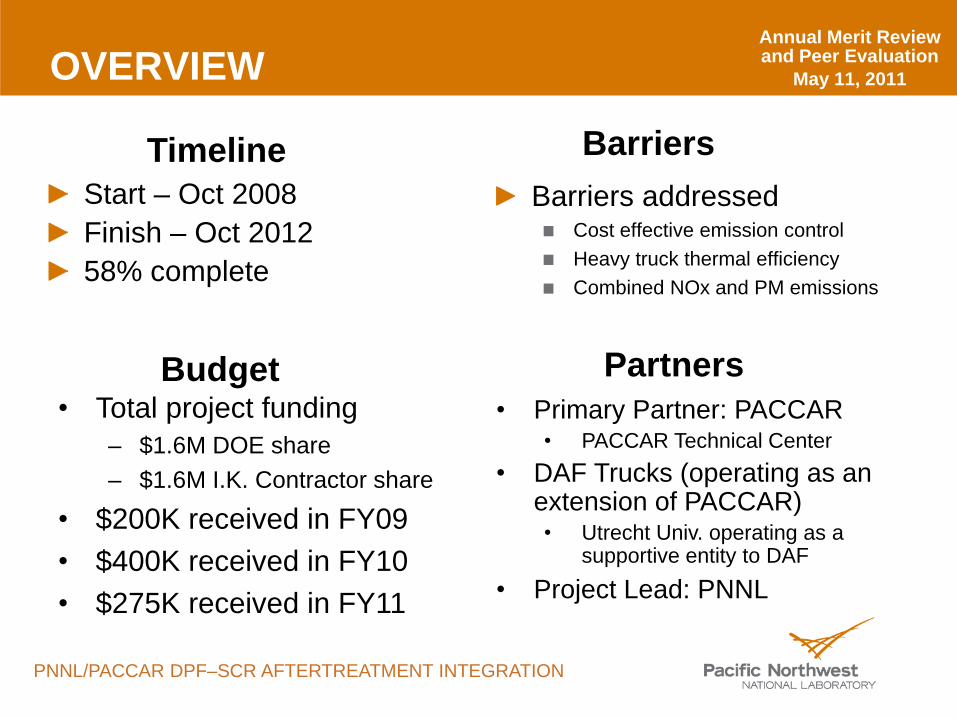
OVERVIEW
Start – Oct 2008Finish – Oct 201258% complete
Barriers addressedCost effective emission controlHeavy truck thermal efficiencyCombined NOx and PM emissions
• Total project funding– $1.6M DOE share– $1.6M I.K. Contractor share
• $200K received in FY09• $400K received in FY10• $275K received in FY11
Timeline
Budget
Barriers
• Primary Partner: PACCAR• PACCAR Technical Center
• DAF Trucks (operating as an extension of PACCAR)• Utrecht Univ. operating as a
supportive entity to DAF
• Project Lead: PNNL
Partners
Annual Merit Review and Peer Evaluation
May 11, 2011
PNNL/PACCAR DPF–SCR AFTERTREATMENT INTEGRATION
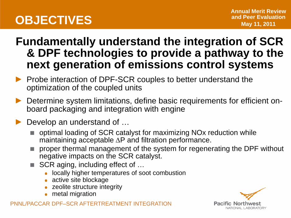
OBJECTIVES
Fundamentally understand the integration of SCR & DPF technologies to provide a pathway to the next generation of emissions control systemsProbe interaction of DPF-SCR couples to better understand the optimization of the coupled unitsDetermine system limitations, define basic requirements for efficient on-board packaging and integration with engineDevelop an understand of …
optimal loading of SCR catalyst for maximizing NOx reduction while maintaining acceptable ∆P and filtration performance.proper thermal management of the system for regenerating the DPF without negative impacts on the SCR catalyst.SCR aging, including effect of …
locally higher temperatures of soot combustionactive site blockagezeolite structure integritymetal migration
Annual Merit Review and Peer Evaluation
May 11, 2011
PNNL/PACCAR DPF–SCR AFTERTREATMENT INTEGRATION
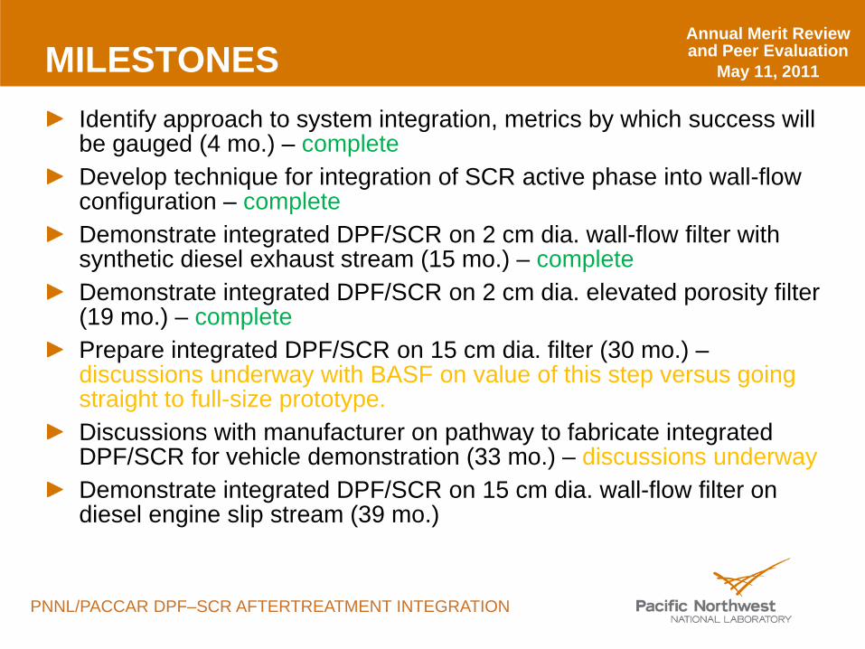
MILESTONESIdentify approach to system integration, metrics by which success will be gauged (4 mo.) – completeDevelop technique for integration of SCR active phase into wall-flow configuration – completeDemonstrate integrated DPF/SCR on 2 cm dia. wall-flow filter with synthetic diesel exhaust stream (15 mo.) – completeDemonstrate integrated DPF/SCR on 2 cm dia. elevated porosity filter (19 mo.) – completePrepare integrated DPF/SCR on 15 cm dia. filter (30 mo.) –discussions underway with BASF on value of this step versus going straight to full-size prototype. Discussions with manufacturer on pathway to fabricate integrated DPF/SCR for vehicle demonstration (33 mo.) – discussions underwayDemonstrate integrated DPF/SCR on 15 cm dia. wall-flow filter on diesel engine slip stream (39 mo.)
Annual Merit Review and Peer Evaluation
May 11, 2011
PNNL/PACCAR DPF–SCR AFTERTREATMENT INTEGRATION
APPROACH/STRATEGYFlow restriction concerns
∆P: SCR/DPF > SCR + cDPFBack pressure dependant on filter type, filter specifications, washcoat technique & loadingMaximize NOx reduction performance, maximize PM filtration performance, minimize flow restriction
Optimal SCR catalyst loadingVersus effect on filter permeability, particulate filtration performance, DPF regeneration performance
Thermal managementMinimizing impact on SCR catalyst
Detailed interrogations evaluating SCR catalyst impact (Utrecht)Address NOx conversion with accumulated soot
Annual Merit Review and Peer Evaluation
May 11, 2011
PNNL/PACCAR DPF–SCR AFTERTREATMENT INTEGRATION
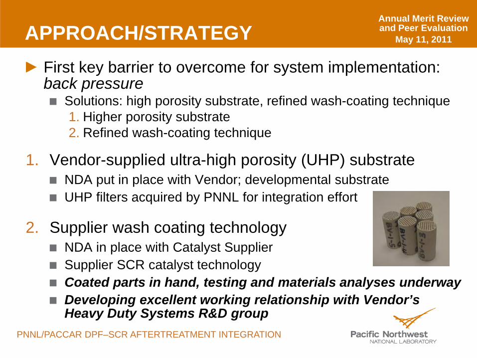
APPROACH/STRATEGYFirst key barrier to overcome for system implementation: back pressure
Solutions: high porosity substrate, refined wash-coating technique1. Higher porosity substrate2. Refined wash-coating technique
1. Vendor-supplied ultra-high porosity (UHP) substrateNDA put in place with Vendor; developmental substrateUHP filters acquired by PNNL for integration effort
2. Supplier wash coating technologyNDA in place with Catalyst SupplierSupplier SCR catalyst technologyCoated parts in hand, testing and materials analyses underwayDeveloping excellent working relationship with Vendor’s Heavy Duty Systems R&D group
Annual Merit Review and Peer Evaluation
May 11, 2011
PNNL/PACCAR DPF–SCR AFTERTREATMENT INTEGRATION
0
0.04
0.08
0.12
0.16
0.2
0.24
0.010.1110100
Incr
emen
tal P
ore
Volu
me
(mL/
g)
Pore Diameter (µm)
~150 g/L Catalyst ~54% porosity
~90 g/L Catalyst ~53% porosity
~60 g/L Catalyst ~60% porosity
No Catalyst ~68% porosity
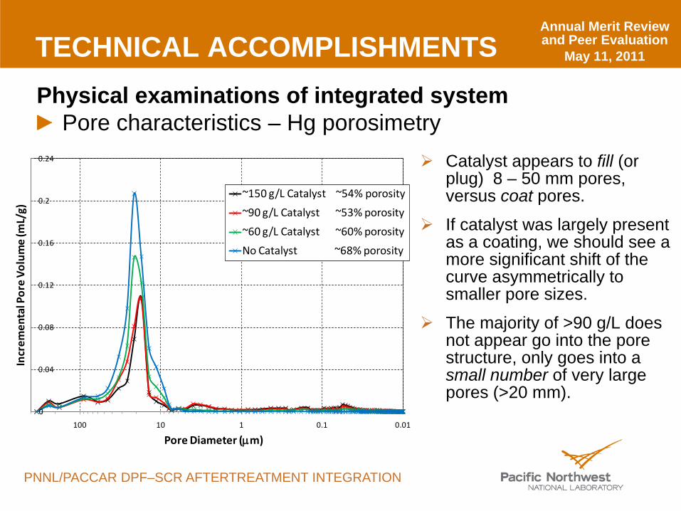
TECHNICAL ACCOMPLISHMENTSPhysical examinations of integrated system
Pore characteristics – Hg porosimetry Catalyst appears to fill (or
plug) 8 – 50 mm pores, versus coat pores.
If catalyst was largely present as a coating, we should see a more significant shift of the curve asymmetrically to smaller pore sizes.
The majority of >90 g/L does not appear go into the pore structure, only goes into a small number of very large pores (>20 mm).
Annual Merit Review and Peer Evaluation
May 11, 2011
PNNL/PACCAR DPF–SCR AFTERTREATMENT INTEGRATION
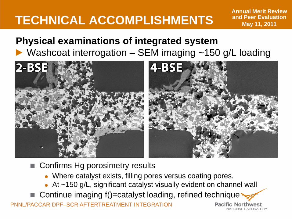
TECHNICAL ACCOMPLISHMENTSPhysical examinations of integrated system
Washcoat interrogation – SEM imaging ~150 g/L loading
Confirms Hg porosimetry resultsWhere catalyst exists, filling pores versus coating pores.At ~150 g/L, significant catalyst visually evident on channel wall
Continue imaging f()=catalyst loading, refined technique
Annual Merit Review and Peer Evaluation
May 11, 2011
PNNL/PACCAR DPF–SCR AFTERTREATMENT INTEGRATION
0%
20%
40%
60%
80%
100%
0 100 200 300 400 500 600
NO
xRe
duct
ion
Effi
cien
cy
Temperature, °C
~150 g/L SCR Catalyst
~90 g/L SCR Catalyst
~60 g/L SCR Catalyst
Flow Through Catalyst
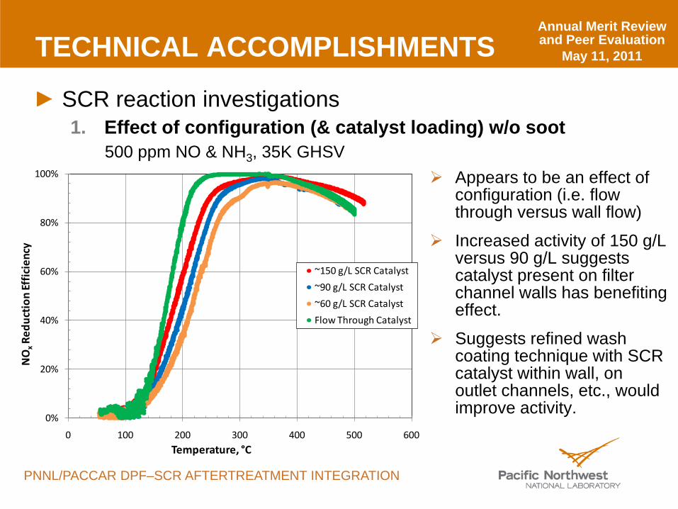
TECHNICAL ACCOMPLISHMENTS
SCR reaction investigations1. Effect of configuration (& catalyst loading) w/o soot
500 ppm NO & NH3, 35K GHSV Appears to be an effect of
configuration (i.e. flow through versus wall flow)
Increased activity of 150 g/Lversus 90 g/L suggests catalyst present on filter channel walls has benefiting effect.
Suggests refined wash coating technique with SCR catalyst within wall, on outlet channels, etc., would improve activity.
Annual Merit Review and Peer Evaluation
May 11, 2011
PNNL/PACCAR DPF–SCR AFTERTREATMENT INTEGRATION
0%
10%
20%
30%
40%
50%
60%
70%
80%
90%
100%
0 100 200 300 400 500
NO
xRe
duct
ion
Effi
cien
cy
Temperature, °C
~90 g/L Catalyst Loading
Clean filter
with ~3 g/L soot
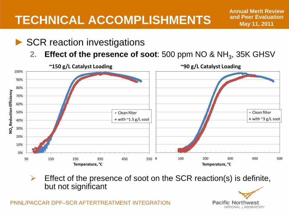
TECHNICAL ACCOMPLISHMENTS
SCR reaction investigations2. Effect of the presence of soot: 500 ppm NO & NH3, 35K GHSV
Effect of the presence of soot on the SCR reaction(s) is definite, but not significant
0%
10%
20%
30%
40%
50%
60%
70%
80%
90%
100%
50 150 250 350 450 550
NO
xRe
duct
ion
Effi
cien
cy
Temperature, °C
~150 g/L Catalyst Loading
Clean filter
with ~1.5 g/L soot
Annual Merit Review and Peer Evaluation
May 11, 2011
PNNL/PACCAR DPF–SCR AFTERTREATMENT INTEGRATION
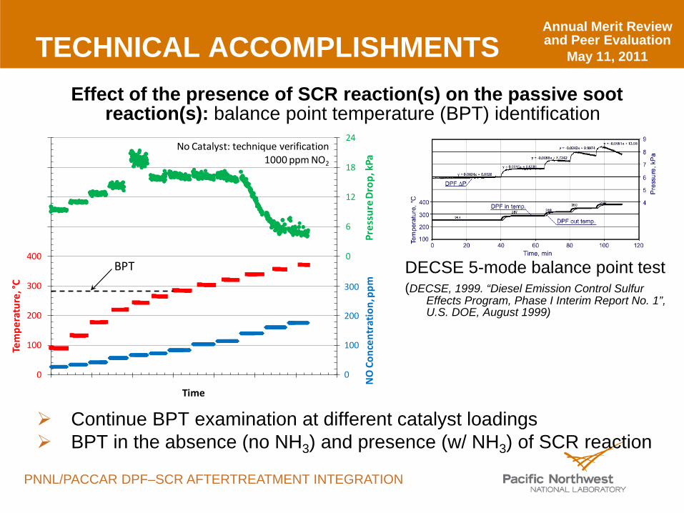
TECHNICAL ACCOMPLISHMENTSEffect of the presence of SCR reaction(s) on the passive soot
reaction(s): balance point temperature (BPT) identification
DECSE 5-mode balance point test(DECSE, 1999. “Diesel Emission Control Sulfur
Effects Program, Phase I Interim Report No. 1”, U.S. DOE, August 1999)
Continue BPT examination at different catalyst loadings BPT in the absence (no NH3) and presence (w/ NH3) of SCR reaction
-24
-18
-12
-6
0
6
12
18
24
0
100
200
300
400
500
600
700
800
0 0 0 1 1 1 1 1
Pres
sure
Dro
p, k
Pa
Tem
pera
ture
, °C
Time
300
200
100
0N
O C
once
ntra
tion
, ppm
BPT
No Catalyst: technique verification1000 ppm NO2
Annual Merit Review and Peer Evaluation
May 11, 2011
PNNL/PACCAR DPF–SCR AFTERTREATMENT INTEGRATION
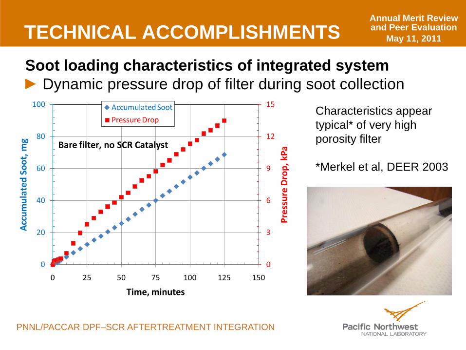
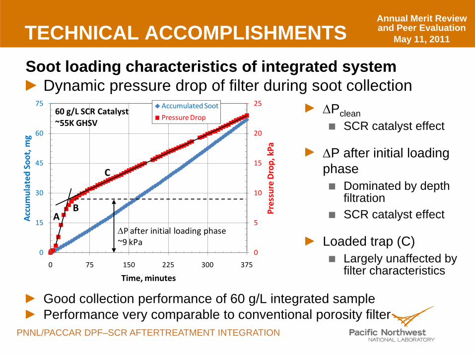
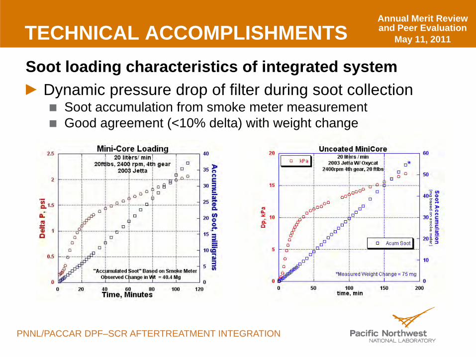
TECHNICAL ACCOMPLISHMENTSSoot loading characteristics of integrated system
Dynamic pressure drop of filter during soot collectionCharacteristics appear typical* of very high porosity filter
*Merkel et al, DEER 2003
0
3
6
9
12
15
0
20
40
60
80
100
0 25 50 75 100 125 150Pr
essu
re D
rop,
kPa
Acc
umul
ated
Soo
t, m
g
Time, minutes
Accumulated Soot
Pressure Drop
Bare filter, no SCR Catalyst
Annual Merit Review and Peer Evaluation
May 11, 2011
PNNL/PACCAR DPF–SCR AFTERTREATMENT INTEGRATION
TECHNICAL ACCOMPLISHMENTSSoot loading characteristics of integrated system
Dynamic pressure drop of filter during soot collection
Good collection performance of 60 g/L integrated samplePerformance very comparable to conventional porosity filter
∆PcleanSCR catalyst effect
∆P after initial loading phase
Dominated by depth filtrationSCR catalyst effect
Loaded trap (C)Largely unaffected by filter characteristics
0
5
10
15
20
25
0
15
30
45
60
75
0 75 150 225 300 375Pr
essu
re D
rop,
kPa
Acc
umul
ated
Soo
t, m
g
Time, minutes
Accumulated Soot
Pressure Drop
AB
C
∆P after initial loading phase~9 kPa
60 g/L SCR Catalyst~55K GHSV
Annual Merit Review and Peer Evaluation
May 11, 2011
PNNL/PACCAR DPF–SCR AFTERTREATMENT INTEGRATION
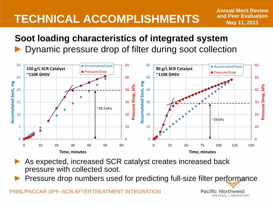
TECHNICAL ACCOMPLISHMENTSSoot loading characteristics of integrated system
Dynamic pressure drop of filter during soot collection
As expected, increased SCR catalyst creates increased back pressure with collected soot.Pressure drop numbers used for predicting full-size filter performance
0
10
20
30
40
50
60
0
10
20
30
40
50
60
0 25 50 75 100 125 150
Pres
sure
Dro
p, k
Pa
Acc
umul
ated
Soo
t, m
g
Time, minutes
Accumulated Soot
Pressure Drop90 g/L SCR Catalyst~110K GHSV
~29 kPa
0
10
20
30
40
50
60
0
5
10
15
20
25
30
0 10 20 30 40 50 60
Pres
sure
Dro
p, k
Pa
Acc
umul
ated
Soo
t, m
g
Time, minutes
Accumulated Soot
Pressure Drop150 g/L SCR Catalyst~110K GHSV
~39.5 kPa
Annual Merit Review and Peer Evaluation
May 11, 2011
PNNL/PACCAR DPF–SCR AFTERTREATMENT INTEGRATION
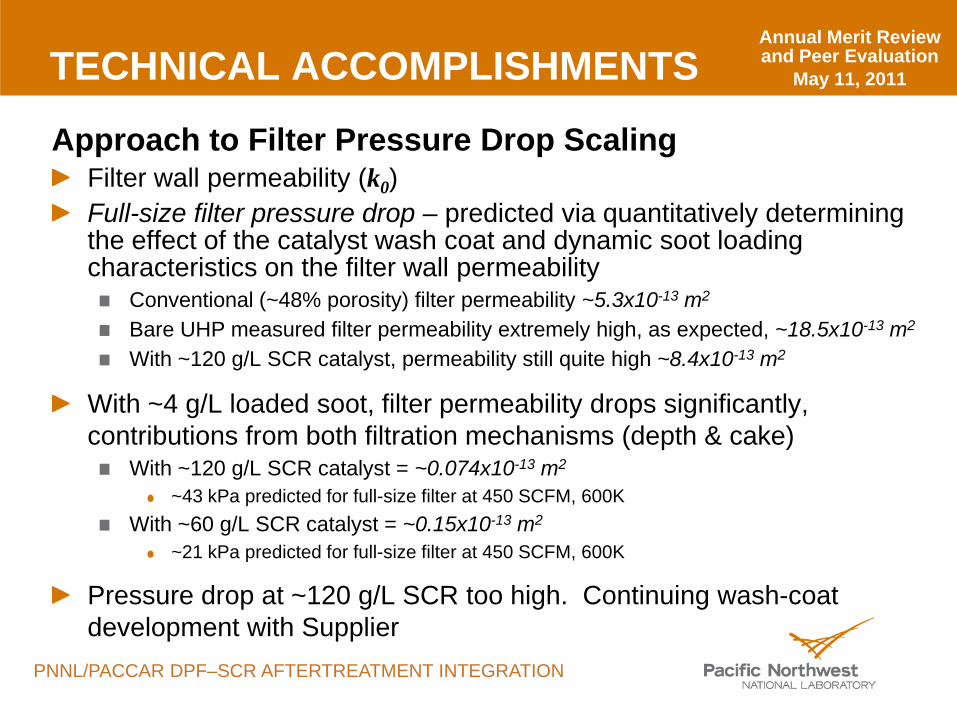
TECHNICAL ACCOMPLISHMENTS
Approach to Filter Pressure Drop ScalingFilter wall permeability (k0)Full-size filter pressure drop – predicted via quantitatively determining the effect of the catalyst wash coat and dynamic soot loading characteristics on the filter wall permeability
Conventional (~48% porosity) filter permeability ~5.3x10⁻¹³ m2
Bare UHP measured filter permeability extremely high, as expected, ~18.5x10⁻¹³ m2
With ~120 g/L SCR catalyst, permeability still quite high ~8.4x10⁻¹³ m2
With ~4 g/L loaded soot, filter permeability drops significantly, contributions from both filtration mechanisms (depth & cake)
With ~120 g/L SCR catalyst = ~0.074x10⁻¹³ m2
~43 kPa predicted for full-size filter at 450 SCFM, 600KWith ~60 g/L SCR catalyst = ~0.15x10⁻¹³ m2
~21 kPa predicted for full-size filter at 450 SCFM, 600K
Pressure drop at ~120 g/L SCR too high. Continuing wash-coat development with Supplier
Annual Merit Review and Peer Evaluation
May 11, 2011
PNNL/PACCAR DPF–SCR AFTERTREATMENT INTEGRATION
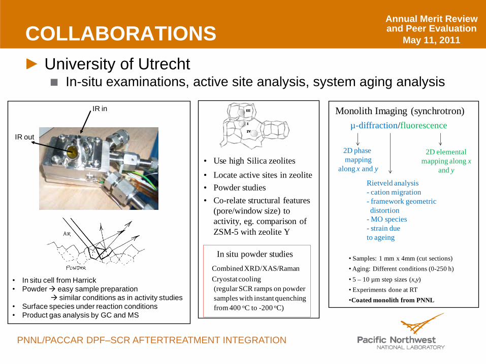
COLLABORATIONSUniversity of Utrecht
In-situ examinations, active site analysis, system aging analysis
• Use high Silica zeolites• Locate active sites in zeolite• Powder studies• Co-relate structural features
(pore/window size) to activity, eg. comparison of ZSM-5 with zeolite Y
Combined XRD/XAS/RamanCryostat cooling (regular SCR ramps on powder samples with instant quenching from 400 oC to -200 oC)
In situ powder studies • Samples: 1 mm x 4mm (cut sections)• Aging: Different conditions (0-250 h)• 5 – 10 µm step sizes (x,y)• Experiments done at RT•Coated monolith from PNNL
µ-diffraction/fluorescence
2D elemental mapping along x
and y
Rietveld analysis- cation migration- framework geometric distortion
- MO species- strain dueto ageing
2D phase mapping
along x and y
Monolith Imaging (synchrotron)
• In situ cell from Harrick• Powder easy sample preparation
similar conditions as in activity studies• Surface species under reaction conditions• Product gas analysis by GC and MS
IR in
IR out
Annual Merit Review and Peer Evaluation
May 11, 2011
PNNL/PACCAR DPF–SCR AFTERTREATMENT INTEGRATION
FUTURE WORK (2011)Continuing wash-coat development strategy with Vendor:
Uniform dispersion throughout the wallLoading heavy to the inlet & outlet sides and channel wallsOther parameters Supplier will guide on, including:
Varying rheological and/or wicking characteristicsImmersion strategy (time, repetition, etc.)
Continuing system kinetic and performance investigationsEffect of soot & soot oxidation on NOx SCR reactionEffect of SCR reaction on soot oxidationIntegrated system soot filtration performance
… as a function of catalyst mass loading, catalyst configuration within filter, etc.
Annual Merit Review and Peer Evaluation
May 11, 2011
PNNL/PACCAR DPF–SCR AFTERTREATMENT INTEGRATION
SUMMARY
NDAs in place with Vendors for UHP substrate and substrate:catalyst integrated systemsIntegrated system samples in hand, currently under investigationExaminations interrogating the physical system as well as kinetic and dynamic performance of integrated system
NOx SCR performance looks good. Continuing SCR integration strategy to maximize SCR performancePressure drop performance of integrated system during dynamic soot collection is limiting. Continuing development with Supplier.
Results of examinations will provide feedback to Supplier to guide on system integration efforts to ultimately direct towards an optimum integrated device
Annual Merit Review and Peer Evaluation
May 11, 2011
PNNL/PACCAR DPF–SCR AFTERTREATMENT INTEGRATION
TECHNICAL BACK-UP SLIDES
TECHNICAL BACK-UP SLIDES
Annual Merit Review and Peer Evaluation
May 11, 2011
PNNL/PACCAR DPF–SCR AFTERTREATMENT INTEGRATION
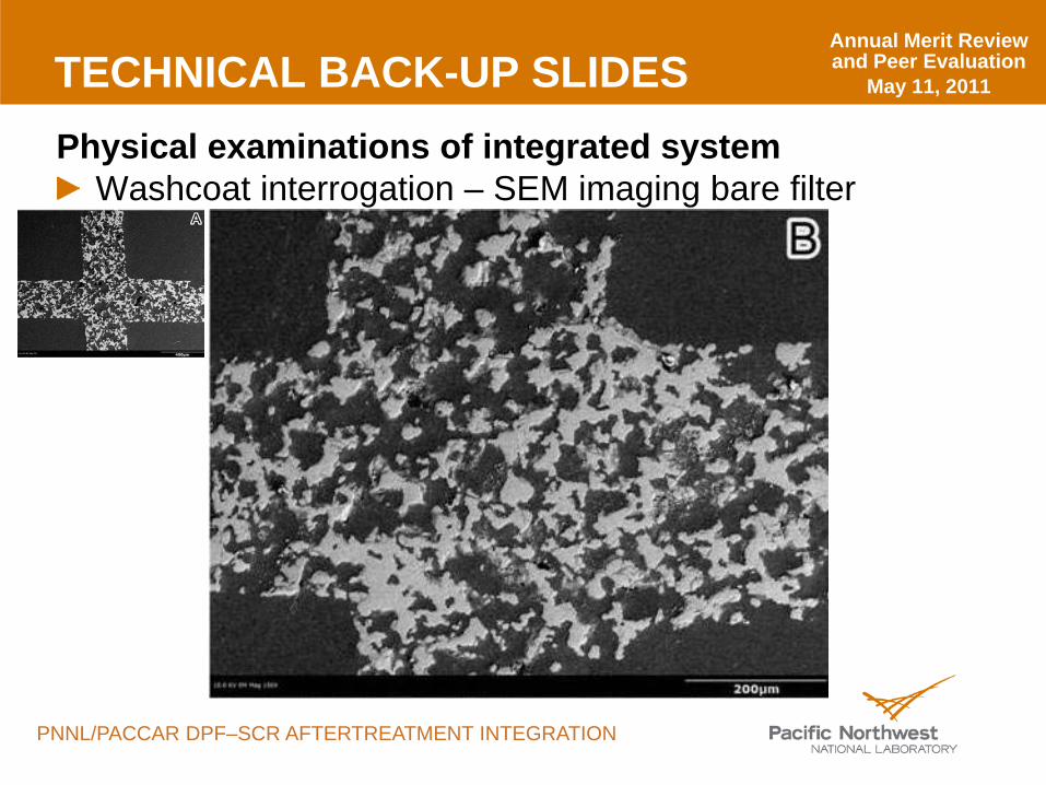
TECHNICAL BACK-UP SLIDESPhysical examinations of integrated system
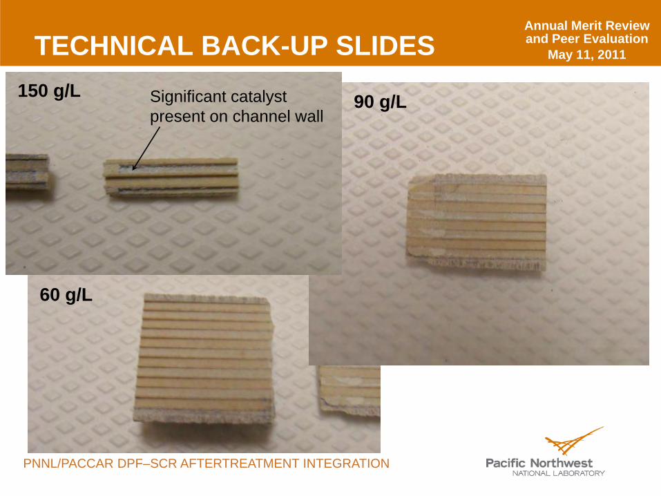
Washcoat interrogation – SEM imaging bare filter
Annual Merit Review and Peer Evaluation
May 11, 2011
PNNL/PACCAR DPF–SCR AFTERTREATMENT INTEGRATION
TECHNICAL BACK-UP SLIDES150 g/L 90 g/L
60 g/L
Significant catalyst present on channel wall
Annual Merit Review and Peer Evaluation
May 11, 2011
PNNL/PACCAR DPF–SCR AFTERTREATMENT INTEGRATION
TECHNICAL ACCOMPLISHMENTSSoot loading characteristics of integrated system
Dynamic pressure drop of filter during soot collectionSoot accumulation from smoke meter measurementGood agreement (<10% delta) with weight change
Annual Merit Review and Peer Evaluation
May 11, 2011
PNNL/PACCAR DPF–SCR AFTERTREATMENT INTEGRATION
TECHNICAL BACK-UP SLIDES
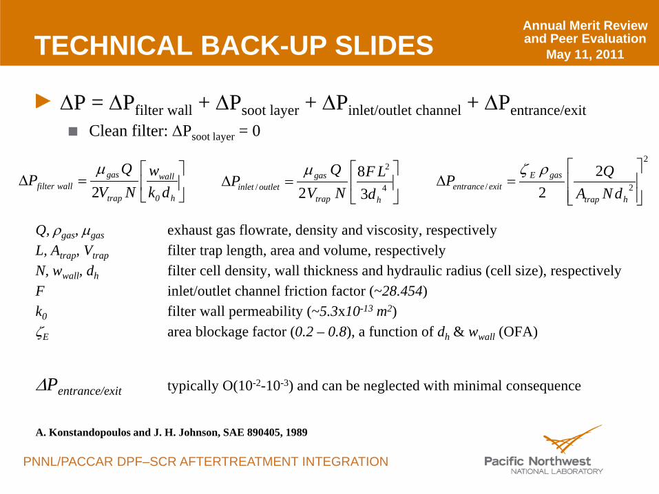
∆P = ∆Pfilter wall + ∆Psoot layer + ∆Pinlet/outlet channel + ∆Pentrance/exitClean filter: ∆Psoot layer = 0
Q, ρgas, µgas exhaust gas flowrate, density and viscosity, respectivelyL, Atrap, Vtrap filter trap length, area and volume, respectivelyN, wwall, dh filter cell density, wall thickness and hydraulic radius (cell size), respectivelyF inlet/outlet channel friction factor (~28.454)k0 filter wall permeability (~5.3x10⁻¹³ m2)ζE area blockage factor (0.2 – 0.8), a function of dh & wwall (OFA)
∆Pentrance/exit typically O(10-2-10-3) and can be neglected with minimal consequence
A. Konstandopoulos and J. H. Johnson, SAE 890405, 1989
=∆
h0
wall
trap
gaswallfilter dk
wNV
QP
2µ
=∆ 4
2
/ 38
2 htrap
gasoutletinlet d
LFNV
QP
µ2
2/2
2
=∆
htrap
gasEexitentrance dNA
QPρζ
Annual Merit Review and Peer Evaluation
May 11, 2011
PNNL/PACCAR DPF–SCR AFTERTREATMENT INTEGRATION
TECHNICAL BACK-UP SLIDES
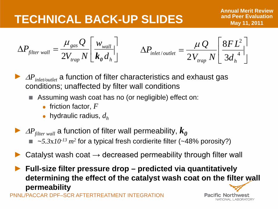
∆Pinlet/outlet a function of filter characteristics and exhaust gas conditions; unaffected by filter wall conditions
Assuming wash coat has no (or negligible) effect on:friction factor, Fhydraulic radius, dh
∆Pfilter wall a function of filter wall permeability, k0~5.3x10⁻¹³ m2 for a typical fresh cordierite filter (~48% porosity?)
Catalyst wash coat → decreased permeability through filter wall
Full-size filter pressure drop – predicted via quantitatively determining the effect of the catalyst wash coat on the filter wall permeability
=∆
h
wall
trap
gaswallfilter d
wNV
QP
0k2µ
=∆ 4
2
/ 38
2 htrapoutletinlet d
LFNV
QP µ