Embed Size (px)
Citation preview

1
COM Express® Type 10 Mini Carrier CCG022
Connect Tech Inc. Tel: 519-836-1291
42 Arrow Road Toll: 800-426-8979 (North America only) Guelph, Ontario Fax: 519-836-4878 N1K 1S6 Email: [email protected] www.connecttech.com [email protected] CTIM-00489 Revision 0.00 2017-08-01

COM Express Type 10 PC Connector Carrier Manual
Users Guide
www.connecttech.com
Document: CTIM-00489
Revision: 0.00 Page 2 of 38
Connect Tech Inc. 800-426-8979 | 519-836-1291
Date: 2017-08-01
Table of Contents
Table of Contents ................................................................................................................................... 1
Preface ................................................................................................................................................... 4
Disclaimer ....................................................................................................................................................... 4 Customer Support Overview ........................................................................................................................... 4 Contact Information ........................................................................................................................................ 4 Limited Product Warranty ............................................................................................................................... 5 Copyright Notice ............................................................................................................................................. 5 Trademark Acknowledgment .......................................................................................................................... 5 ESD Warning .................................................................................................................................................. 6
Revision History .................................................................................................................................... 6
Introduction........................................................................................................................................... 7
Product Features and Specifications ................................................................................................................ 7 Part Numbers / Ordering Information ............................................................................................................. 8
Product Overview .................................................................................................................................. 9
CCG022 Block Diagram ................................................................................................................................. 9 Connector Summary & Locations ................................................................................................................. 10
CCG022 Top View ............................................................................................................................. 10 CCG022 Bottom View ....................................................................................................................... 10
Jumper Summary ........................................................................................................................................... 11
Detailed Feature Pinouts and Functional Descriptions ......................................................................... 12
COM Express Module ................................................................................................................................... 12 Display Outputs ............................................................................................................................................. 13
LVDS Video Connector ..................................................................................................................... 13 LVDS Backlight Power Connector .................................................................................................... 14 HDMI Video Connector ..................................................................................................................... 15
USB ............................................................................................................................................................... 16 USB 2.0 Port Connectors .................................................................................................................... 16 USB 3.0/2.0 Port Connectors.............................................................................................................. 16
10/100/1000 Ethernet (GBE) Connector ....................................................................................................... 17 Software Support for the Intel 82574 ................................................................................................. 17
Serial ............................................................................................................................................................. 18 RS-232/485 Connector ....................................................................................................................... 18 RS-232/485 Jumper Configuration ..................................................................................................... 19
J1 – RS-232/485 Jumper Block ......................................................................................................................................... 19 Serial Line Modes .............................................................................................................................................................. 19 Examples ........................................................................................................................................................................... 19
Audio ............................................................................................................................................................. 20 Software Support for the CS4207 ....................................................................................................... 20
microSD Card Connector .............................................................................................................................. 21 mini PCIe & mSATA Slots ........................................................................................................................... 22
Dual Function mini PCIe mSATA Slots ............................................................................................. 22 Half and Full Length mini PCIe / mSATA module Installation ......................................................... 23 Standoff and Screw Assembly Details ................................................................................................ 23 CCG022 – External Hard Drive Installation ....................................................................................... 24 mini pcie / mSATA Connector Pinout ................................................................................................ 25
System Miscellaneous ................................................................................................................................... 26 System Connector ............................................................................................................................... 26 J2 – System Jumper Block .................................................................................................................. 26
Input Power & Control .................................................................................................................................. 27
COM Express Type 10 PC Connector Carrier Manual
Users Guide
www.connecttech.com
Document: CTIM-00489
Revision: 0.00 Page 3 of 38
Connect Tech Inc. 800-426-8979 | 519-836-1291
Date: 2017-08-01
RTC Battery .................................................................................................................................................. 27
Typical Hardware Installation Procedure ............................................................................................ 28
On-board Indicator LED ............................................................................................................................... 28
Power Consumption and Thermals ...................................................................................................... 29
Current Consumption .................................................................................................................................... 29 Thermal Properties ........................................................................................................................................ 30
Mechanical Drawings & Models .......................................................................................................... 31
Cable Kits ............................................................................................................................................ 32
CCG022 Cable Kit - CKG044 – “Full” Cable Kit ........................................................................................ 32
Appendix A – COM Express Signal/Pinout Connection Details ............................................................ 33
COM Express Type 10 PC Connector Carrier Manual
Users Guide
www.connecttech.com
Document: CTIM-00489
Revision: 0.00 Page 4 of 38
Connect Tech Inc. 800-426-8979 | 519-836-1291
Date: 2017-08-01
Preface Disclaimer
The information contained within this user’s guide, including but not limited to any product specification, is
subject to change without notice.
Connect Tech assumes no liability for any damages incurred directly or indirectly from any technical or
typographical errors or omissions contained herein or for discrepancies between the product and the user’s
guide.
Customer Support Overview
If you experience difficulties after reading the manual and/or using the product, contact the Connect Tech
reseller from which you purchased the product. In most cases the reseller can help you with product installation
and difficulties. In the event that the reseller is unable to resolve your problem, our highly qualified support
staff can assist you. Our support section is available 24 hours a day, 7 days a week on our website at:
http://connecttech.com/support/. See the contact information section below for more information on how to
contact us directly. Our technical support is always free.
Contact Information
Mail/Courier Connect Tech Inc.
Technical Support
42 Arrow Road
Guelph, Ontario
Canada N1K 1S6
Email/Internet [email protected]
www.connecttech.com
Note:
Please go to the Resource Center or the Support Center on the Connect Tech website for product
manuals, installation guides, device driver software and technical tips.
Submit your technical support questions to our customer support engineers via the Support Center on the
Connect Tech website.
Telephone/Facsimile
Technical Support representatives are ready to answer your call Monday through Friday, from 8:30 a.m. to
5:00 p.m. Eastern Standard Time. Our numbers for calls are: Toll Free: 800-426-8979 (North America only)
Telephone: 519-836-1291 (Live assistance available 8:30 a.m. to 5:00 p.m. EST,
Monday to Friday)
Facsimile: 519-836-4878 (on-line 24 hours)

COM Express Type 10 PC Connector Carrier Manual
Users Guide
www.connecttech.com
Document: CTIM-00489
Revision: 0.00 Page 5 of 38
Connect Tech Inc. 800-426-8979 | 519-836-1291
Date: 2017-08-01
Limited Product Warranty Connect Tech Inc. provides a two-year Warranty for the COM Express® Type 10 PC Connector Carrier Board.
Should this product, in Connect Tech Inc.'s opinion, fail to be in good working order during the warranty
period, Connect Tech Inc. will, at its option, repair or replace this product at no charge, provided that the
product has not been subjected to abuse, misuse, accident, disaster or non-Connect Tech Inc. authorized
modification or repair.
You may obtain warranty service by delivering this product to an authorized Connect Tech Inc. business
partner or to Connect Tech Inc. along with proof of purchase. Product returned to Connect Tech Inc. must be
pre-authorized by Connect Tech Inc. with an RMA (Return Material Authorization) number marked on the
outside of the package and sent prepaid, insured and packaged for safe shipment. Connect Tech Inc. will
return this product by prepaid ground shipment service.
The Connect Tech Inc. Limited Warranty is only valid over the serviceable life of the product. This is defined
as the period during which all components are available. Should the product prove to be irreparable, Connect
Tech Inc. reserves the right to substitute an equivalent product if available or to retract the Warranty if no
replacement is available.
The above warranty is the only warranty authorized by Connect Tech Inc. Under no circumstances will
Connect Tech Inc. be liable in any way for any damages, including any lost profits, lost savings or other
incidental or consequential damages arising out of the use of, or inability to use, such product.
Copyright Notice
The information contained in this document is subject to change without notice. Connect Tech Inc. shall not
be liable for errors contained herein or for incidental consequential damages in connection with the furnishing,
performance, or use of this material. This document contains proprietary information that is protected by
copyright. All rights are reserved. No part of this document may be photocopied, reproduced, or translated to
another language without the prior written consent of Connect Tech, Inc.
Copyright 2017 by Connect Tech, Inc.
Trademark Acknowledgment
Connect Tech, Inc. acknowledges all trademarks, registered trademarks and/or copyrights referred to in this
document as the property of their respective owners.
Not listing all possible trademarks or copyright acknowledgments does not constitute a lack of
acknowledgment to the rightful owners of the trademarks and copyrights mentioned in this document.

COM Express Type 10 PC Connector Carrier Manual
Users Guide
www.connecttech.com
Document: CTIM-00489
Revision: 0.00 Page 6 of 38
Connect Tech Inc. 800-426-8979 | 519-836-1291
Date: 2017-08-01
ESD Warning
Electronic components and circuits are sensitive to
ElectroStatic Discharge (ESD). When handling any circuit
board assemblies including Connect Tech COM Express
carrier assemblies, it is recommended that ESD safety
precautions be observed. ESD safe best practices include,
but are not limited to:
Leaving circuit boards in their antistatic packaging
until they are ready to be installed.
Using a grounded wrist strap when handling circuit
boards, at a minimum you should touch a grounded
metal object to dissipate any static charge that may be
present on you.
Only handling circuit boards in ESD safe areas, which
may include ESD floor and table mats, wrist strap
stations and ESD safe lab coats.
Avoiding handling circuit boards in carpeted areas.
Try to handle the board by the edges, avoiding contact
with components.
Revision History
Revision Date Changes
0.00 2017-08-01 Original Release

COM Express Type 10 PC Connector Carrier Manual
Users Guide
www.connecttech.com
Document: CTIM-00489
Revision: 0.00 Page 7 of 38
Connect Tech Inc. 800-426-8979 | 519-836-1291
Date: 2017-08-01
Introduction
Connect Tech’s COM Express® Type 10 PC Connector Carrier is an extremely small carrier board featuring a
combination of PC style connectors and locking pin header connectors. The carrier has a robust offering, with 2x
USB 3.0 Type A ports, 2x USB 2.0 Type A ports, 1x HDMI, 1x LVDS interface, and 2x GbE.
The COM Express Type 10 PC Connector Carrier Board provides support for the latest generation of low-powered
CPUs. It is ideal for space constrained applications and supports extended temperature ranges of -40°C to +85°C.
Product Features and Specifications
Specifications
Compatibility COM Express® Type 10 Mini Modules PICMG COM Express® COM.0 R2.1
Mini PCIe Expansion 2 x half size cards OR 1 x full length card Both sockets have PCIe and USB signaling, one socket also can be configured as mSATA.
Storage 1 x mSATA
USB 2 x USB 3.0 Ports (Only if supported by COM Express Module) 6 x USB 2.0 Ports (2 to USB 3.0 connector, 2 to USB 2.0 connector, 2 to miniPCIe)
Network 2 x Gigabit Ethernet (10/10/1000) Ports: 1 from COM Express 1 from on-board Intel 82574I PHY/Controller
GPIO 8-bit GPIO
Display 1 x HDMI 1 x LVDS
Audio HD Audio (Cirrus Logic CS4207 codec) 1 x stereo input 1 x stereo output
Serial 2 x RS-232/422/485 hardware selectable ports
Misc External Interfaces SMBus I2C Battery Low Indication System Status (S3 and Reset Outputs)
Power Single wide input range +8V to +14V DC (may be module dependent)
RTC Battery No on-board RTC battery Option to connect external RTC battery.
Connectors USB Type A, RJ45, HDMI connectors, additional signals via shrouded locking ruggedized 2mm pitch headers. Can be mated to CTI custom cable set to panel mount or PC MIL type connectors
Mechanical Information 84mm x 73.415mm
CCG022: Download 3D model here
Weight 68g (carrier only, no module installed)
Operating Temperature -40°C to +85°C

COM Express Type 10 PC Connector Carrier Manual
Users Guide
www.connecttech.com
Document: CTIM-00489
Revision: 0.00 Page 8 of 38
Connect Tech Inc. 800-426-8979 | 519-836-1291
Date: 2017-08-01
Part Numbers / Ordering Information
Part Number
CCG022 COM Express® Type 10 PC Connector Carrier

COM Express Type 10 PC Connector Carrier Manual
Users Guide
www.connecttech.com
Document: CTIM-00489
Revision: 0.00 Page 9 of 38
Connect Tech Inc. 800-426-8979 | 519-836-1291
Date: 2017-08-01
Product Overview
CCG022 Block Diagram

COM Express Type 10 PC Connector Carrier Manual
Users Guide
www.connecttech.com
Document: CTIM-00489
Revision: 0.00 Page 10 of 38
Connect Tech Inc. 800-426-8979 | 519-836-1291
Date: 2017-08-01
Connector Summary & Locations
CCG022 Top View
CCG022 Bottom View

COM Express Type 10 PC Connector Carrier Manual
Users Guide
www.connecttech.com
Document: CTIM-00489
Revision: 0.00 Page 11 of 38
Connect Tech Inc. 800-426-8979 | 519-836-1291
Date: 2017-08-01
Designator Description
P1 GBE0/1 Connector (2x1 RJ45 Connector)
P3 microSD Card Connector
P4 Input Power Connector
P5 RTC Battery Connector
P6 USB 3.0 Connector
P7 RS-232/485 Connector
P8 COM Express Type 10 Connector
P9 LVDS Video Connector
P10 LVDS Backlight Power Connector
P11 HDMI Connector
P12 Misc/System Connector
P13 Audio Input/Output Connector
P14 USB 2.0 Port 2 & 3 Connector
P15 miniPCIe Slot-1 SIM Socket
Jumper Summary
Designator Description
J1 RS-232/RS-485 Jumper Block
J2 System Jumper Block
COM Express Type 10 PC Connector Carrier Manual
Users Guide
www.connecttech.com
Document: CTIM-00489
Revision: 0.00 Page 12 of 38
Connect Tech Inc. 800-426-8979 | 519-836-1291
Date: 2017-08-01
Detailed Feature Pinouts and Functional Descriptions
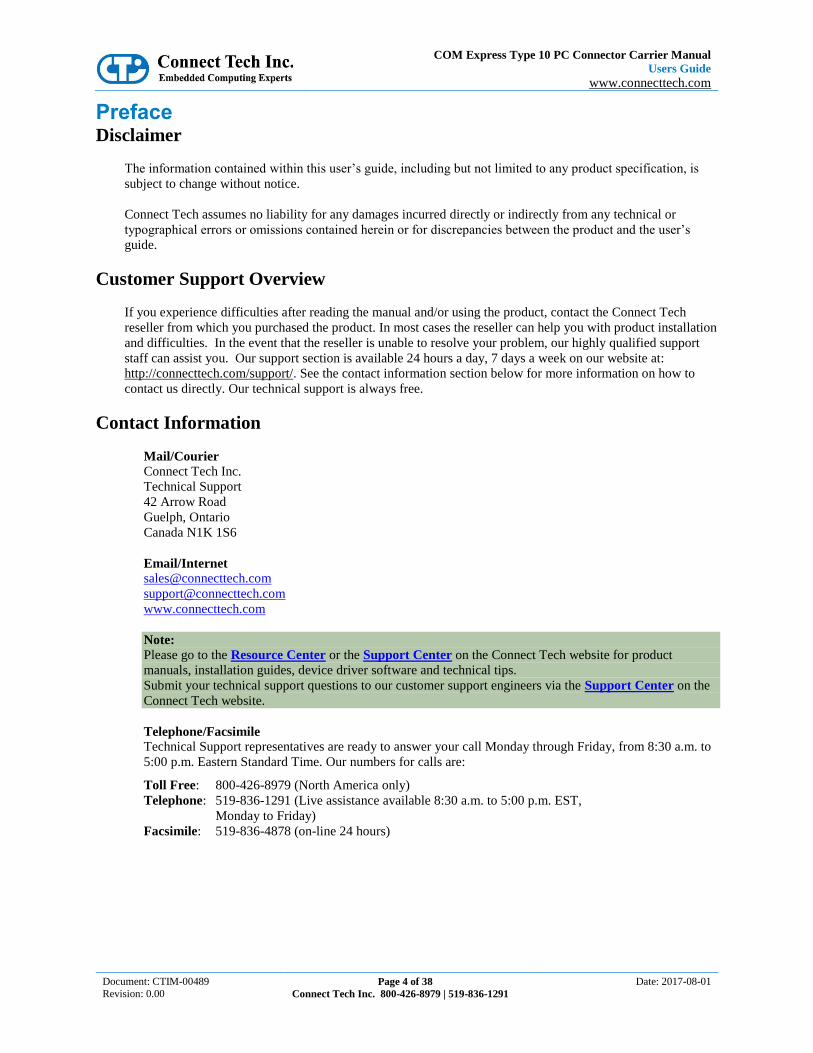
COM Express Module
The processor and chipset are implemented on the COM Express Type 10 CPU module, which connects to the
COM Express carrier via a Tyco fine pitch stacking connector.
Function COM Express interface
Location P8
Carrier Connector PN
3-6318491-6 Manufacturer: TE Connectivity
Mating Connector PN
3-1827231-6 Manufacturer: TE Connectivity
Pinout See Appendix A

COM Express Type 10 PC Connector Carrier Manual
Users Guide
www.connecttech.com
Document: CTIM-00489
Revision: 0.00 Page 13 of 38
Connect Tech Inc. 800-426-8979 | 519-836-1291
Date: 2017-08-01
Display Outputs
LVDS Video Connector
The COM Express carrier provides dual 18 or 24 bit LVDS display channels via P9, which are connected
directly from the COM Express module.
Function LVDS Graphics
Location P9
Carrier Connector PN
DF19G-20P-1H(54) - Manufacturer: Hirose
Mating Connector PN
DF19-20S-1C - Manufacturer: Hirose
Pinout Pin Signal Description
1 +3.3 VCC_PNL Panel Power
2 +3.3 VCC_PNL Panel Power
3 GND Digital ground
4 GND Digital ground
5 LVDS_A0_N Channel A Data
6 LVDS_A0_P Channel A Data
7 GND Digital ground
8 LVDS_A1_N Channel A Data
9 LVDS_A1_P Channel A Data
10 GND Digital ground
11 LVDS_A2_N Channel A Data
12 LVDS_A2_P Channel A Data
13 GND Digital ground
14 LVDS_CLK_N Channel A Data
15 LVDS_CLK_P Channel A Data
16 GND Digital ground
17 +5 VCC_PNL [1] Backlight Power
18 +5 VCC_PNL [1] Backlight Power
19 GND Digital ground
20 BKLT Control [2] LED ADJ
[1] – +5V_VCC_PNL – This voltage can be enabled or disabled to the display via Jumper J2 position B.
[2] – BKLT Control – This signal can be connected to the COM Express backlight control pin or to GND via Jumper J2
position C and D.

COM Express Type 10 PC Connector Carrier Manual
Users Guide
www.connecttech.com
Document: CTIM-00489
Revision: 0.00 Page 14 of 38
Connect Tech Inc. 800-426-8979 | 519-836-1291
Date: 2017-08-01
LVDS Backlight Power Connector
The COM Express Type 10 PC Connector Carrier is equipped with a LVDS backlight inverter power supply
connector. This power supply is designed to power HDA700LPT-GHL (or similar screen type) which has 13
parallel strings of 3 series white LEDS. Each white LED has a Vf of approximately 3.3V.
Function LVDS backlight Inverter power
Location P10
Carrier Connector PN
SM02B-BHSS-1-TB - Manufacturer: JST
Mating Connector PN
BHSR-02VS-1 (N) - Manufacturer: JST
Pinout Pin Signal
1 VA LED
2 VK LED

COM Express Type 10 PC Connector Carrier Manual
Users Guide
www.connecttech.com
Document: CTIM-00489
Revision: 0.00 Page 15 of 38
Connect Tech Inc. 800-426-8979 | 519-836-1291
Date: 2017-08-01
HDMI Video Connector
The COM Express Type 10 PC Connector Carrier features a HDMI connector.
Function HDMI Output Connector
Location P11
Carrier Connector PN
2007435-3 - Manufacturer: TE
Mating Connector PN
Standard HDMI Type A Plug
Pinout Standard HDMI Type A pinout.
COM Express Type 10 PC Connector Carrier Manual
Users Guide
www.connecttech.com
Document: CTIM-00489
Revision: 0.00 Page 16 of 38
Connect Tech Inc. 800-426-8979 | 519-836-1291
Date: 2017-08-01
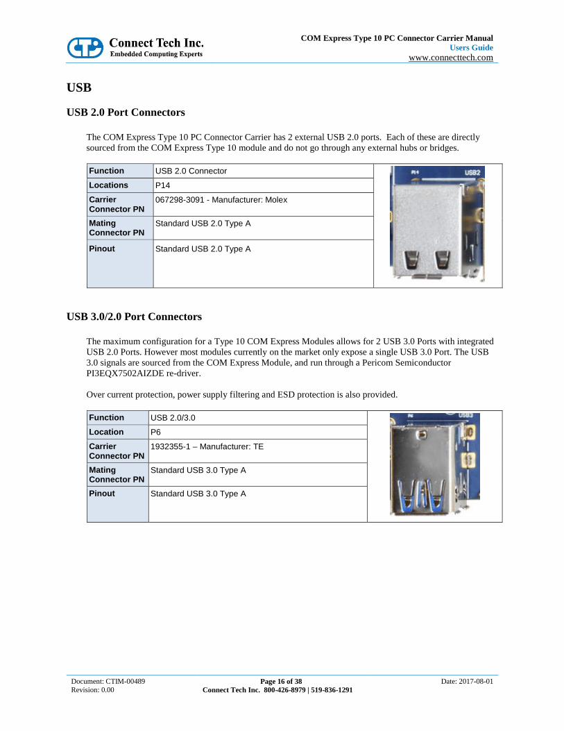
USB
USB 2.0 Port Connectors
The COM Express Type 10 PC Connector Carrier has 2 external USB 2.0 ports. Each of these are directly
sourced from the COM Express Type 10 module and do not go through any external hubs or bridges.
Function USB 2.0 Connector
Locations P14
Carrier Connector PN
067298-3091 - Manufacturer: Molex
Mating Connector PN
Standard USB 2.0 Type A
Pinout Standard USB 2.0 Type A
USB 3.0/2.0 Port Connectors
The maximum configuration for a Type 10 COM Express Modules allows for 2 USB 3.0 Ports with integrated
USB 2.0 Ports. However most modules currently on the market only expose a single USB 3.0 Port. The USB
3.0 signals are sourced from the COM Express Module, and run through a Pericom Semiconductor
PI3EQX7502AIZDE re-driver.
Over current protection, power supply filtering and ESD protection is also provided.
Function USB 2.0/3.0
Location P6
Carrier Connector PN
1932355-1 – Manufacturer: TE
Mating Connector PN
Standard USB 3.0 Type A
Pinout Standard USB 3.0 Type A

COM Express Type 10 PC Connector Carrier Manual
Users Guide
www.connecttech.com
Document: CTIM-00489
Revision: 0.00 Page 17 of 38
Connect Tech Inc. 800-426-8979 | 519-836-1291
Date: 2017-08-01
10/100/1000 Ethernet (GBE) Connector
The COM Express Type 10 PC Connector Carrier features dual 10/100/1000 Ethernet Ports.
GBE Port 1 is coming directly from the COM Express module.
GBE Port 2 is coming from an Intel 82574 PCIe PHY Controller located on the carrier.
Function LAN Connector
Locations P1
Carrier Connector PN
RJHSE-5381-02 - Manufacturer: Amphenol
Mating Connector PN
Standard 10/100/1000 RJ45 Ethernet; refer to IEEE 802.3
Pinout Standard 10/100/1000 RJ45 Ethernet; refer to IEEE 802.3
Software Support for the Intel 82574
Additional drivers will be needed to properly operate the GBE Port 2 on the COM Express carrier.
These drivers can be downloaded directly from Intel website from the below link:
http://downloadcenter.intel.com/SearchResult.aspx?lang=eng&ProductFamily=Ethernet+Components&Produc
tLine=Ethernet+Controllers&ProductProduct=Intel%C2%AE+82574+Gigabit+Ethernet+Controller

COM Express Type 10 PC Connector Carrier Manual
Users Guide
www.connecttech.com
Document: CTIM-00489
Revision: 0.00 Page 18 of 38
Connect Tech Inc. 800-426-8979 | 519-836-1291
Date: 2017-08-01
Serial
The COM Express Type 10 PC Connector Carrier provides 2 asynchronous serial ports. Each of these ports
are derived directly from the COM Express Type 10 SER1 and SER2 connections. These ports are hardware
selectable through he means of jumpers to RS-232 or RS-422/485
RS-232/485 Connector
Function RS-232 / RS-485
Locations P7
Carrier Connector PN
98424-G52-10LF - Manufacturer: FCI
Mating Connector PN
10073599-010LF - Manufacturer: FCI
Pinout Pin Signal Description
1 232TX0/485TX0+ RS-232 0 Transmit / RS-485 0 Transmit +
2 232RX0/485RX0+ RS-232 0 Transmit / RS-485 0 Transmit +
3 485TX0- RS-485 0 Transmit -
4 485RX0- RS-485 0 Transmit -
5 232/485-GND0 Port 0 Ground
6 232/485-GND1 Port 1 Ground
7 232TX1/485TX1+ RS-232 1 Transmit / RS-485 1 Transmit +
8 232RX1/485RX+ RS-232 1 Transmit / RS-485 1 Transmit +
9 485TX1- RS-485 1 Transmit -
10 485RX1+ RS-485 1 Receive -

COM Express Type 10 PC Connector Carrier Manual
Users Guide
www.connecttech.com
Document: CTIM-00489
Revision: 0.00 Page 19 of 38
Connect Tech Inc. 800-426-8979 | 519-836-1291
Date: 2017-08-01
RS-232/485 Jumper Configuration
Below is a listing of the 3 main configurations of jumper settings for the serial ports on the carrier board.
Positions A & B set the line mode, while positions C – F set BIAS termination for RS-485 signaling.
J1 – RS-232/485 Jumper Block
Position Jumper Description
A Serial Mode Bit - M0
B Serial Mode Bit – M1
C Port 0 RS-485 BIAS+
D Port 0 RS-485 BIAS-
E Port 1 RS-485 BIAS+
F Port 1 RS-485 BIAS-
Serial Line Modes
Position A – M0 Position B – M1 Port 0 Selected Mode Port 1 Selected Mode
OFF OFF RS-232 RS-232
OFF ON RS-422/485 RS-422/485
ON OFF RS-232 RS-422/485
ON ON Undefined Undefined
Examples

COM Express Type 10 PC Connector Carrier Manual
Users Guide
www.connecttech.com
Document: CTIM-00489
Revision: 0.00 Page 20 of 38
Connect Tech Inc. 800-426-8979 | 519-836-1291
Date: 2017-08-01
Audio
The COM Express Type 10 PC Connector Carrier features HD Audio capabilities care of the Cirrus Logic
CS4207 Codec device. From the codec 1 input (microphone) and 1 output (headphone) are available.
Function Audio Connector
Locations P13
Carrier Connector PN
98424-G52-10LF - Manufacturer: FCI
Mating Connector PN
10073599-010LF - Manufacturer: FCI
Pinout Pin Signal Description
1 - No Connect
2 - No Connect
3 MIC-R Mic Input - Right Channel
4 MIC-L Mic Input - Left Channel
5 GND Mic GND / Shield
6 GND Headphone GND / Shield
7 HPOUT-R Headphone Right Channel
8 HPOUT-L Headphone Left Channel
Software Support for the CS4207
The audio codec used on the carrier board is the CS4207 from Cirrus Logic.
Additional drivers will be needed to properly operate audio on the COM Express carrier. Some downloadable
ldrivers can be found below.
https://www.cirrus.com/products/cs4207/
Linux Driver: Included in kernels 2.6.30 and up.

COM Express Type 10 PC Connector Carrier Manual
Users Guide
www.connecttech.com
Document: CTIM-00489
Revision: 0.00 Page 21 of 38
Connect Tech Inc. 800-426-8979 | 519-836-1291
Date: 2017-08-01
microSD Card Connector
The COM Express Type 10 PC Connector Carrier provides a Micro SD Card Slot at P3. This Micro SD Card
slot sources the SDIO interface from the COM Express modules GPIO pins.
** Note this SD card slot will ONLY operate if the COM Express module provides the SDIO interface over the
GPIO pins. Some COM Express modules may have this as a BIOS setting, others will be strictly a hardware
option. See below for the SDIO / GPIO mapping **
Function Micro SD Card Slot
Locations P3
Carrier Connector PN
502570-0893 - Manufacturer: Molex
Pinout Pin SDIO Signal COM Express GPIO Mapping
1 SD_D2 GPI2
2 SD_D3 GPI3
3 SD_CMD GPO1
4 SD_VCC (+3.3V) -
5 SD_CLK GPO0
6 GND -
7 SD_D0 GPI0
8 SD_D1 GPI1
9 GND -
10 SD_CD# GP03

COM Express Type 10 PC Connector Carrier Manual
Users Guide
www.connecttech.com
Document: CTIM-00489
Revision: 0.00 Page 22 of 38
Connect Tech Inc. 800-426-8979 | 519-836-1291
Date: 2017-08-01
mini PCIe & mSATA Slots
Dual Function mini PCIe mSATA Slots
The COM Express Type 10 PC Connector Carrier has a standard mini PCIe slot and a special dual purpose
functionality mini PCIe / mSATA slot. The dual purpose slot can accept either a mini PCIe module or an
mSATA SSD module. These slots have special circuitry that allows for the selection between connecting PCIe
lanes or SATA lanes.
Each slot is also provided with a USB 2.0 connection in addition to the PCIe as per the mini PCIe
specification; see below for a block diagram of the slots functionality.
Standard mini PCIe Slot Block Diagram (U19)
Note: SIM card is only connected to the “left” mini pcie Slot 1
PCIe / SATA Dual Functionality Diagram (U12)
** Selection between mSATA and mini pcie is done via Jumper J2 position E. (ON = mini pcie, OFF = mSATA)

COM Express Type 10 PC Connector Carrier Manual
Users Guide
www.connecttech.com
Document: CTIM-00489
Revision: 0.00 Page 23 of 38
Connect Tech Inc. 800-426-8979 | 519-836-1291
Date: 2017-08-01
Half and Full Length mini PCIe / mSATA module Installation
The COM Express Type 10 PC Connector Carrier’s mini pcie / mSATA slots are designed for easy ruggedized
selection between full and half-length modules. This is done via the installation of M2.5 threaded standoffs.
Standoffs and screws are provided with the shipping configuration of the carrier board. Below are some
examples of how the various modules sizes can be installed.
Two Half Length Modules Installed
One Full Length mini pcie Module Installed
One Full Length mSATA Module Installed
Standoff and Screw Assembly Details
Below is a diagram of how the standoffs and mounting hardware should be installed. If the screw mount type
standoffs is not preferred a solder-in standoff is also available.
COM Express Type 10 PC Connector Carrier Manual
Users Guide
www.connecttech.com
Document: CTIM-00489
Revision: 0.00 Page 24 of 38
Connect Tech Inc. 800-426-8979 | 519-836-1291
Date: 2017-08-01
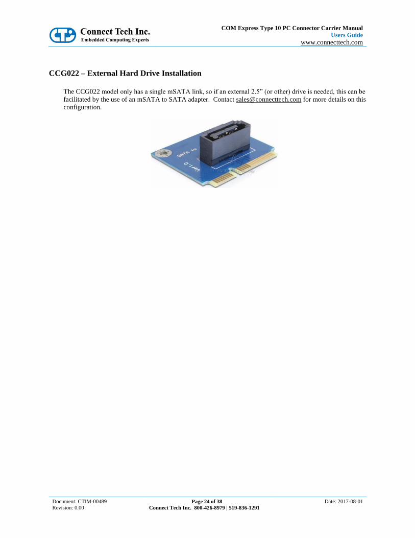
CCG022 – External Hard Drive Installation
The CCG022 model only has a single mSATA link, so if an external 2.5” (or other) drive is needed, this can be
facilitated by the use of an mSATA to SATA adapter. Contact [email protected] for more details on this
configuration.

COM Express Type 10 PC Connector Carrier Manual
Users Guide
www.connecttech.com
Document: CTIM-00489
Revision: 0.00 Page 25 of 38
Connect Tech Inc. 800-426-8979 | 519-836-1291
Date: 2017-08-01
mini pcie / mSATA Connector Pinout
Function mini PCIe / mSATA Slots
Locations U19 (“left slot” mini pcie) U12 (“right slot” mini pcie/mSATA)
Carrier Connector PN
Standard 52-pin 0.8mm pitch PCI Express mini Card connector
Pinout mSATA PinoutPin Number Description
1 NC
2 +3.3V
3 NC
4 GND
5 NC
6 +1.5V
7 NC
8 NC
9 GND
10 NC
11 NC
12 NC
13 NC
14 NC
15 GND
16 NC
17 NC
18 GND
19 NC
20 NC
21 RESV
22 NC
23 SATA TX+ To Host System
24 +3.3V
25 SATA TX- To Host System
26 GND
27 GND
28 +1.5V
29 GND
30 NC
31 SATA RX- From Host System
32 NC
33 SATA RX+ From Host System
34 GND
35 GND
36 NC
37 GND
38 NC
39 +3.3V
40 GND
41 +3.3V
42 NC
43 RESV
44 NC
45 NC
46 NC
47 NC
48 +1.5V
49 NC
50 GND
51 NC
52 +3.3V
mini pcie PinoutPin Number Description
1 NC
2 +3.3V
3 NC
4 GND
5 NC
6 +1.5V
7 CLKREQ#
8 UIM_PWR
9 GND
10 UIM_DATA
11 PCIe CLK+
12 UIM_CLK
13 PCIe CLK-
14 UIM_RESET
15 GND
16 UIM_VPP
17 NC
18 GND
19 NC
20 W_DISABLE#
21 RESV
22 NC
23 PCIe RX+ To Host System
24 +3.3V
25 PCIe RX- To Host System
26 GND
27 GND
28 +1.5V
29 GND
30 SMB_CLK
31 PCIe TX- From Host System
32 SMB_DATA
33 PCIe TX+ From Host System
34 GND
35 GND
36 USB D-
37 GND
38 USB D+
39 +3.3V
40 GND
41 +3.3V
42 NC
43 RESV
44 NC
45 NC
46 NC
47 NC
48 +1.5V
49 NC
50 GND
51 NC
52 +3.3V

COM Express Type 10 PC Connector Carrier Manual
Users Guide
www.connecttech.com
Document: CTIM-00489
Revision: 0.00 Page 26 of 38
Connect Tech Inc. 800-426-8979 | 519-836-1291
Date: 2017-08-01
System Miscellaneous
System Connector
This system control header can be used to connect power button, reset button, PC speaker, I2C device and
monitor other power rails.
Function Misc/System Control Header
Location P12
Carrier Connector PN
98424-G52-20LF - Manufacturer: FCI
Mating Connector PN
10073599-020LF - Manufacturer: FCI
Pinout Pin Signal Description
1 PWRM.PWRBTN# Power Button
2 GND Ground
3 PWRM.SYS_RESET# Reset Button
4 GND Ground
5 PWRM.SUS_S3# S3 Power Status Output
6 SMB.ALERT# SMB Alert Signal
7 RESET-OUT# Carrier Board Reset Output
8 SMB.DAT SMB Data
9 GPO0 GPIO Output Bit-0
10 SMB.CK SMB Clock
11 GPO1 GPIO Output Bit-1
12 PWRM.BATLOW# Battery Low Indicator
13 GPO2 GPIO Output Bit-2
14 I2C.CK I2C Clock
15 GPO3 GPIO Output Bit-3
16 I2C.DAT I2C Data
17 GPI0 GPIO Input Bit-0
18 GPI2 GPIO Input Bit-2
19 GPI1 GPIO Input Bit-1
20 GPI3 GPIO Input Bit-3
J2 – System Jumper Block
Position Jumper Description
A SD Card (ON) / GPIO (OFF) selection
B Enable +5V Backlight Supply to P9
C Connect LVDS PWM Signal to GND
D Connect LVDS PWM to COM Express
E mini PCIe (ON) / mSATA (OFF) selection
F SUS_S3# Functionality Enabled (ON) / Disabled (OFF)

COM Express Type 10 PC Connector Carrier Manual
Users Guide
www.connecttech.com
Document: CTIM-00489
Revision: 0.00 Page 27 of 38
Connect Tech Inc. 800-426-8979 | 519-836-1291
Date: 2017-08-01
Input Power & Control
The COM Express Type 10 PC Connector Carrier accepts a single input to power all of the on board devices.
All intermediate voltages are derived from this input. Most COM Express Type 10 module can accept a wide
input voltage range, however the on-board power supplies on CTI’s carrier can only accept up to a maximum
+14V.
Function Main Input Power
Location P4
Input Range +8 VDC to +14 VDC
Carrier Connector PN
98424-G52-06LF - Manufacturer: FCI
Mating Connector PN
10073599-006LF - Manufacturer: FCI
Pinout
Pin Signal Description
1 GND Ground / Return
2 GND Ground / Return
3 GND Ground / Return
4 +VIN Power In
5 +VIN Power In
6 +VIN Power In
RTC Battery
The COM Express Type 10 PC Connector Carrier allows for an external RTC battery to be connected. This
battery should be a 3V DC battery, and it will hold all BIOS settings including date and time. Some COM
Express modules may have the RTC battery on the module so in this case this connector can be left
disconnected.
Connect Tech provides a Battery with cable assembly in any of the “Full” or “Starter” cable kits, please see the
Cable Section of this manual for more details. If this battery is not sufficient for the application, a different
battery cable can be designed.
For further information about RTC battery selection and life time estimation, see Application Note 00009
CTIN-00009 http://connecttech.com/pdf/CTIN-00009.pdf
Function RTC Battery Connector
Location P5
Battery Voltage
+3V DC
Carrier Connector PN
53047-0310 - Manufacturer: Molex
Mating Connector PN
51021-0300 - Manufacturer: Molex
Pinout
Pin Signal Description
1 +3V RTC Battery Voltage Input
2 NC No Connect
3 GND Ground / Return
COM Express Type 10 PC Connector Carrier Manual
Users Guide
www.connecttech.com
Document: CTIM-00489
Revision: 0.00 Page 28 of 38
Connect Tech Inc. 800-426-8979 | 519-836-1291
Date: 2017-08-01
Typical Hardware Installation Procedure
1. Ensure all external system power supplies are off.
2. Install the COM Express module. Be sure to follow the manufacturer’s direction for proper
heatsink/heatspreader installation and any other cooling instructions from the manufacturer.
3. Install the necessary cables for the application. At a minimum, this would include:
a) Power cable to the input power connector
b) Connect a video display cable
c) Keyboard and mouse via USB
d) mSATA Hard Drive or bootable USB
4. Connect the power cable to power supply
5. Ensure your power supply is in the range of +8V to +14V DC
6. Switch on the power supply
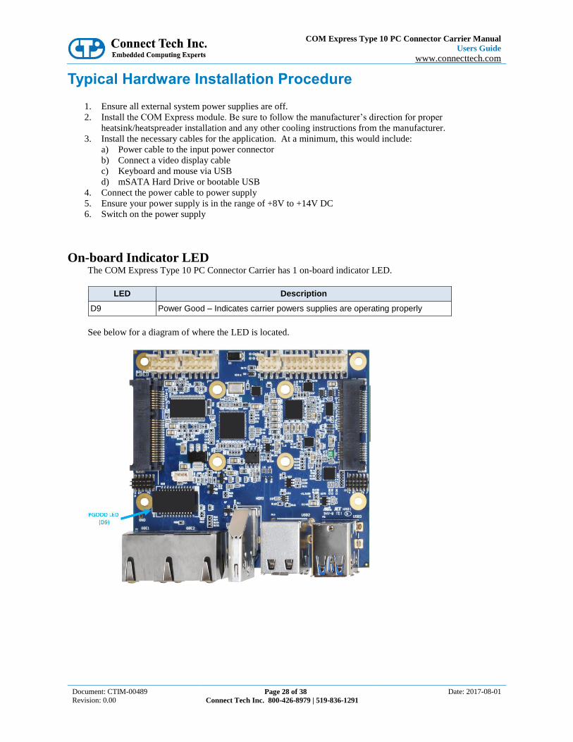
On-board Indicator LED The COM Express Type 10 PC Connector Carrier has 1 on-board indicator LED.
LED Description
D9 Power Good – Indicates carrier powers supplies are operating properly
See below for a diagram of where the LED is located.

COM Express Type 10 PC Connector Carrier Manual
Users Guide
www.connecttech.com
Document: CTIM-00489
Revision: 0.00 Page 29 of 38
Connect Tech Inc. 800-426-8979 | 519-836-1291
Date: 2017-08-01
Power Consumption and Thermals
Current Consumption
Below are some examples of actual measurements taken with the COM Express Type 10 PC Connector Carrier
running in various test configurations. Some values will change depending on what COM Express module is
installed, please refer to the module manufactures manual for full details on the current consumption of the
particular module you are using.
Actual Measurements Amps Watts
Carrier standalone no module installed, powered ON, with no loads 0.14 1.68
Module Installed[1], single DDI video output, USB keyboard with system sitting in BIOS
0.55 6.6
Module Installed[1], single DDI video output, all peripherals connected, booted Linux running, CPU running stress test
1.05 12.6
Note [1]: COM Express Type 10 Module used for measurements - Intel Atom E3815 CPU Note [2]: Input voltage for all tests above was +12V
COM Express Type 10 PC Connector Carrier Manual
Users Guide
www.connecttech.com
Document: CTIM-00489
Revision: 0.00 Page 30 of 38
Connect Tech Inc. 800-426-8979 | 519-836-1291
Date: 2017-08-01
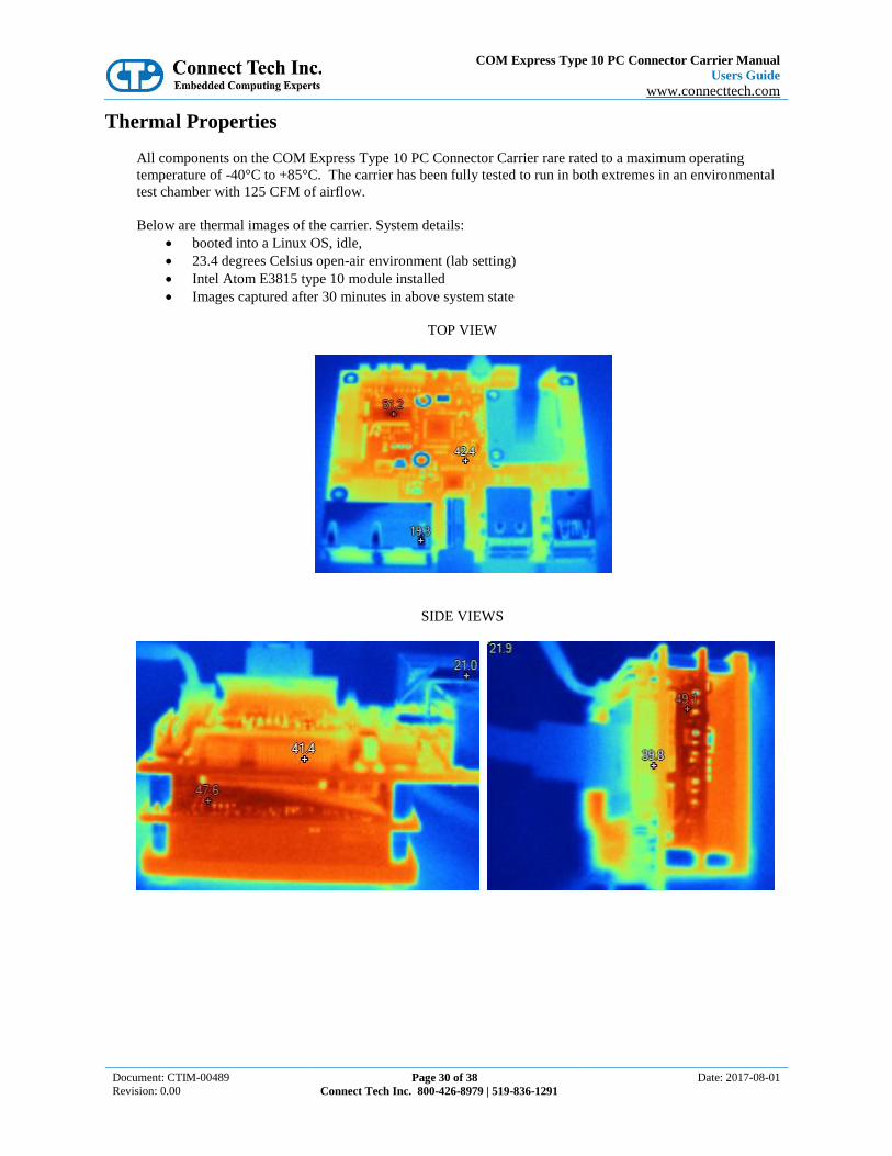
Thermal Properties
All components on the COM Express Type 10 PC Connector Carrier rare rated to a maximum operating
temperature of -40°C to +85°C. The carrier has been fully tested to run in both extremes in an environmental
test chamber with 125 CFM of airflow.
Below are thermal images of the carrier. System details:
booted into a Linux OS, idle,
23.4 degrees Celsius open-air environment (lab setting)
Intel Atom E3815 type 10 module installed
Images captured after 30 minutes in above system state
TOP VIEW
SIDE VIEWS

COM Express Type 10 PC Connector Carrier Manual
Users Guide
www.connecttech.com
Document: CTIM-00489
Revision: 0.00 Page 31 of 38
Connect Tech Inc. 800-426-8979 | 519-836-1291
Date: 2017-08-01
Mechanical Drawings & Models
A complete 3D STEP Model file of carrier board can be downloaded here:
http://www.connecttech.com/ftp/3d_models/CCG022_3D_MODEL.zip
2D Mechanical Dimensioned Drawing

COM Express Type 10 PC Connector Carrier Manual
Users Guide
www.connecttech.com
Document: CTIM-00489
Revision: 0.00 Page 32 of 38
Connect Tech Inc. 800-426-8979 | 519-836-1291
Date: 2017-08-01
Cable Kits
The following table summarizes the carrier’s available cable kits from Connect Tech. These cable kits all
include breakout cables to PC type panel mountable connectors. These cables can be used for production
deployment or for lab bring-up and test purposes.
CCG022 Cable Kit - CKG044 – “Full” Cable Kit
Description Part Number Quantity
Dual DB-9 panel mount to 10-pin MiniTek w/Latch CBG111 1
Power Cable - Unterminated wires to 6-pin MiniTek w/Latch CBG112 1
Dual 3.5mm Stereo Audio panel mount to 8-pin MiniTek w/Latch CBG118 1
System Cable - Unterminated wires to 20-pin MiniTek w/Latch CBG116 1

COM Express Type 10 PC Connector Carrier Manual
Users Guide
www.connecttech.com
Document: CTIM-00489
Revision: 0.00 Page 33 of 38
Connect Tech Inc. 800-426-8979 | 519-836-1291
Date: 2017-08-01
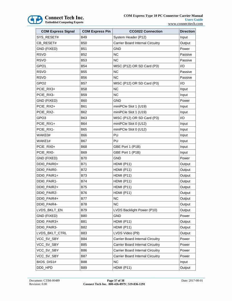
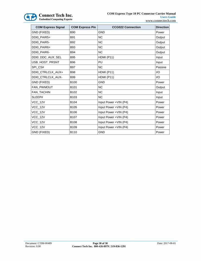
Appendix A – COM Express Signal/Pinout Connection Details
The following table summarizes the COM Express Type-10 Mini Carrier’s COM Express signal/pinout
utilization. From this table you will be able to see which COM Express signals have been used and where
they are connected to on the carrier. No Connection pins are noted as “NC”, pull-ups as “PU”, and pull-downs
as “PD”.
COM Express Signal COM Express Pin CCG022 Connection Direction
GND (FIXED) A1 GND Power
GBE0_MDI3- A2 GBE Port 0 (P1B) I/O
GBE0_MDI3+ A3 GBE Port 0 (P1B) I/O
GBE0_LINK100# A4 GBE Port 0 (P1B) Output
GBE0_LINK1000# A5 GBE Port 0 (P1B) Output
GBE0_MDI2- A6 GBE Port 0 (P1B) I/O
GBE0_MDI2+ A7 GBE Port 0 (P1B) I/O
GBE0_LINK# A8 GBE Port 0 (P1B) Output
GBE0_MDI1- A9 GBE Port 0 (P1B) I/O
GBE0_MDI1+ A10 GBE Port 0 (P1B) I/O
GND (FIXED) A11 GND Power
GBE0_MDI0- A12 GBE Port 0 (P1B) I/O
GBE0_MDI0+ A13 GBE Port 0 (P1B) I/O
GBE0_CTREF A14 GBE Port 0 (P1B) Output
SUS_S3# A15 System Header (P12) Output
SATA0_TX+ A16 mSATA (U12) Output
SATA0_TX- A17 mSATA (U12) Output
SUS_S4# A18 NC Output
SATA0_RX+ A19 mSATA (U12) Input
SATA0_RX- A20 mSATA (U12) Input
GND (FIXED) A21 GND Power
USB_SSRX0- A22 USB 3.0 Port 0 (P6) Input
USB_SSRX0+ A23 USB 3.0 Port 0 (P6) Input
SUS_S5# A24 NC Output
USB_SSRX1- A25 USB 3.0 Port 1 (P6) Input
USB_SSRX1+ A26 USB 3.0 Port 1 (P6) Input
BATLOW# A27 System Header (P12) Input
SATA_ACT# A28 NC Output
HDA_SYNC A29 HD Audio (P13) Output
HDA_RST# A30 HD Audio (P13) Output
GND (FIXED) A31 GND Power
HDA_BITCLK A32 HD Audio (P13) Output
HDA_SDOUT A33 HD Audio (P13) Output
BIOS_DISABLE# A34 NC Input
THRMTRIP# A35 NC Output

COM Express Type 10 PC Connector Carrier Manual
Users Guide
www.connecttech.com
Document: CTIM-00489
Revision: 0.00 Page 34 of 38
Connect Tech Inc. 800-426-8979 | 519-836-1291
Date: 2017-08-01
COM Express Signal COM Express Pin CCG022 Connection Direction
USB6- A36 NC I/O
USB6+ A37 NC I/O
USB_6_7_OC# A38 PU Input
USB4- A39 miniPCIe Slot 0 (U12) I/O
USB4+ A40 miniPCIe Slot 0 (U12) I/O
GND (FIXED) A41 GND Power
USB2- A42 USB 2.0 Port 2 (P14) I/O
USB2+ A43 USB 2.0 Port 2 (P14) I/O
USB_2_3_OC# A44 USB 2.0 Port 2/3 Overcurrent Input
USB0- A45 USB 2.0 Port 0 (P6) I/O
USB0+ A46 USB 2.0 Port 0 (P6) I/O
VCC_RTC A47 RTC Battery (P5) Power
EXCD0_PERST# A48 NC Output
EXCD0_CPPE# A49 NC Input
LPC_SERIRQ A50 NC I/O
GND (FIXED) A51 GND Power
RSVD A52 NC Passive
RSVD A53 NC Passive
GPI0 A54 MISC (P12) OR SD Card (P3) I/O
RSVD A55 NC Passive
RSVD A56 NC Passive
GND A57 GND Power
PCIE_TX3+ A58 NC Output
PCIE_TX3- A59 NC Output
GND (FIXED) A60 GND Power
PCIE_TX2+ A61 miniPCIe Slot 1 (U19) Output
PCIE_TX2- A62 miniPCIe Slot 1 (U19) Output
GPI1 A63 MISC (P12) OR SD Card (P3) I/O
PCIE_TX1+ A64 miniPCIe Slot 0 (U12) Output
PCIE_TX1- A65 miniPCIe Slot 0 (U12) Output
GND A66 GND Power
GPI2 A67 MISC (P12) OR SD Card (P3) I/O
PCIE_TX0+ A68 GBE PHY Controller Output
PCIE_TX0- A69 GBE PHY Controller Output
GND (FIXED) A70 GND Power
LVDS_A0+ A71 LVDS Video (P9) Output
LVDS_A0- A72 LVDS Video (P9) Output
LVDS_A1+ A73 LVDS Video (P9) Output
LVDS_A1- A74 LVDS Video (P9) Output
LVDS_A2+ A75 LVDS Video (P9) Output
LVDS_A2- A76 LVDS Video (P9) Output

COM Express Type 10 PC Connector Carrier Manual
Users Guide
www.connecttech.com
Document: CTIM-00489
Revision: 0.00 Page 35 of 38
Connect Tech Inc. 800-426-8979 | 519-836-1291
Date: 2017-08-01
COM Express Signal COM Express Pin CCG022 Connection Direction
LVDS_VDD_EN A77 LVDS Video (P9) Output
LVDS_A3+ A78 NC Power
LVDS_A3- A79 NC Power
GND (FIXED) A80 GND Power
LVDS_A_CK+ A81 LVDS Video (P9) Output
LVDS_A_CK- A82 LVDS Video (P9) Output
LVDS_I2C_CK A83 NC Output
LVDS_I2C_DAT A84 NC I/O
GPI3 A85 MISC (P12) OR SD Card (P3) I/O
RSVD A86 NC Passive
EDP_HPD A87 NC Passive
PCIE_CLK_REF+ A88 Main Carrier PCIe Clock Output
PCIE_CLK_REF- A89 Main Carrier PCIe Clock Output
GND (FIXED) A90 GND Power
SPI_PWR A91 NC Power
SPI_MISO A92 NC Power
GPO0 A93 GPIO (P12) OR SD Card (P3) I/O
SPI_CLK A94 NC Power
SPI_MOSI A95 NC Power
TPM_PP A96 NC Input
TYPE10# A97 NC Power
SER0_TX A98 Serial Port 0 (P7) Output
SER0_RX A99 Serial Port 0 (P7) Input
GND (FIXED) A100 GND Power
SER1_TX/CAN_TX A101 Serial Port 1 (P7) Output
SER1_RX/CAN_RX A102 Serial Port 1 (P7) Input
LID# A103 NC Input
VCC_12V A104 Input Power +VIN (P4) Power
VCC_12V A105 Input Power +VIN (P4) Power
VCC_12V A106 Input Power +VIN (P4) Power
VCC_12V A107 Input Power +VIN (P4) Power
VCC_12V A108 Input Power +VIN (P4) Power
VCC_12V A109 Input Power +VIN (P4) Power
GND (FIXED) A110 GND Power
GND (FIXED) B1 GND Power
GBE0_ACT# B2 GBE Port 0 (P1B) Output
LPC_FRAME# B3 NC Output
LPC_AD0 B4 NC I/O
LPC_AD1 B5 NC I/O
LPC_AD2 B6 NC I/O
LPC_AD3 B7 NC I/O

COM Express Type 10 PC Connector Carrier Manual
Users Guide
www.connecttech.com
Document: CTIM-00489
Revision: 0.00 Page 36 of 38
Connect Tech Inc. 800-426-8979 | 519-836-1291
Date: 2017-08-01
COM Express Signal COM Express Pin CCG022 Connection Direction
LPC_DRQ0# B8 NC Input
LPC_DRQ1# B9 NC Input
LPC_CLK B10 NC Output
GND (FIXED) B11 GND Power
PWRBTN# B12 System Header (P12) Input
SMB_CK B13 System Header (P12) I/O
SMB_DAT B14 System Header (P12) I/O
SMB_ALERT# B15 System Header (P12) Input
SATA1_TX+ B16 NC Output
SATA1_TX- B17 NC Output
SUS_STAT# B18 NC Output
SATA1_RX+ B19 NC Input
SATA1_RX- B20 NC Input
GND (FIXED) B21 GND Power
USB_SSTX0- B22 USB 3.0 Port 0 (P6) Output
USB_SSTX0+ B23 USB 3.0 Port 0 (P6) Output
PWR_OK B24 Carrier Board Internal Circuitry Input
USB_SSTX1- B25 USB 3.0 Port 1 (P6) Output
USB_SSTX1+ B26 USB 3.0 Port 1 (P6) Output
WDT B27 NC Output
HDA_SDIN2 B28 PD Input
HDA_SDIN1 B29 PD Input
HDA_SDIN0 B30 HD Audio (P13) Input
GND (FIXED) B31 GND Power
SPKR B32 NC Output
I2C_CK B33 System Header (P12) Output
I2C_DAT B34 System Header (P12) I/O
THRM# B35 PU Input
USB7- B36 NC I/O
USB7+ B37 NC I/O
USB_4_5_OC# B38 PU Input
USB5- B39 miniPCIe Slot 1 (U19) I/O
USB5+ B40 miniPCIe Slot 1 (U19) I/O
GND (FIXED) B41 GND Power
USB3- B42 USB 2.0 Port 3 (P14) I/O
USB3+ B43 USB 2.0 Port 3 (P14) I/O
USB_0_1_OC# B44 USB 2.0 Port 0/1 Overcurrent Input
USB1- B45 USB 2.0 Port 1 (P14) I/O
USB1+ B46 USB 2.0 Port 1 (P14) I/O
EXCD1_PERST# B47 NC Output
EXCD1_CPPE# B48 NC Input
COM Express Type 10 PC Connector Carrier Manual
Users Guide
www.connecttech.com
Document: CTIM-00489
Revision: 0.00 Page 37 of 38
Connect Tech Inc. 800-426-8979 | 519-836-1291
Date: 2017-08-01
COM Express Signal COM Express Pin CCG022 Connection Direction
SYS_RESET# B49 System Header (P12) Input
CB_RESET# B50 Carrier Board Internal Circuitry Output
GND (FIXED) B51 GND Power
RSVD B52 NC Passive
RSVD B53 NC Passive
GPO1 B54 MISC (P12) OR SD Card (P3) I/O
RSVD B55 NC Passive
RSVD B56 NC Passive
GPO2 B57 MISC (P12) OR SD Card (P3) I/O
PCIE_RX3+ B58 NC Input
PCIE_RX3- B59 NC Input
GND (FIXED) B60 GND Power
PCIE_RX2+ B61 miniPCIe Slot 1 (U19) Input
PCIE_RX2- B62 miniPCIe Slot 1 (U19) Input
GPO3 B63 MISC (P12) OR SD Card (P3) I/O
PCIE_RX1+ B64 miniPCIe Slot 0 (U12) Input
PCIE_RX1- B65 miniPCIe Slot 0 (U12) Input
WAKE0# B66 PU Input
WAKE1# B67 PU Input
PCIE_RX0+ B68 GBE Port 1 (P1B) Input
PCIE_RX0- B69 GBE Port 1 (P1B) Input
GND (FIXED) B70 GND Power
DDI0_PAIR0+ B71 HDMI (P11) Output
DDI0_PAIR0- B72 HDMI (P11) Output
DDI0_PAIR1+ B73 HDMI (P11) Output
DDI0_PAIR1- B74 HDMI (P11) Output
DDI0_PAIR2+ B75 HDMI (P11) Output
DDI0_PAIR2- B76 HDMI (P11) Output
DDI0_PAIR4+ B77 NC Output
DDI0_PAIR4- B78 NC Output
LVDS_BKLT_EN B79 LVDS Backlight Power (P10) Output
GND (FIXED) B80 GND Power
DDI0_PAIR3+ B81 HDMI (P11) Output
DDI0_PAIR3- B82 HDMI (P11) Output
LVDS_BKLT_CTRL B83 LVDS Video (P9) Output
VCC_5V_SBY B84 Carrier Board Internal Circuitry Power
VCC_5V_SBY B85 Carrier Board Internal Circuitry Power
VCC_5V_SBY B86 Carrier Board Internal Circuitry Power
VCC_5V_SBY B87 Carrier Board Internal Circuitry Power
BIOS_DIS1# B88 NC Input
DD0_HPD B89 HDMI (P11) Output
COM Express Type 10 PC Connector Carrier Manual
Users Guide
www.connecttech.com
Document: CTIM-00489
Revision: 0.00 Page 38 of 38
Connect Tech Inc. 800-426-8979 | 519-836-1291
Date: 2017-08-01
COM Express Signal COM Express Pin CCG022 Connection Direction
GND (FIXED) B90 GND Power
DDI0_PAIR5+ B91 NC Output
DDI0_PAIR5- B92 NC Output
DDI0_PAIR6+ B93 NC Output
DDI0_PAIR6- B94 NC Output
DDI0_DDC_AUX_SEL B95 HDMI (P11) Input
USB_HOST_PRSNT B96 PU Input
SPI_CS# B97 NC Passive
DDI0_CTRLCLK_AUX+ B98 HDMI (P11) I/O
DDI0_CTRLCLK_AUX- B99 HDMI (P11) I/O
GND (FIXED) B100 GND Power
FAN_PWMOUT B101 NC Output
FAN_TACHIN B102 NC Input
SLEEP# B103 NC Input
VCC_12V B104 Input Power +VIN (P4) Power
VCC_12V B105 Input Power +VIN (P4) Power
VCC_12V B106 Input Power +VIN (P4) Power
VCC_12V B107 Input Power +VIN (P4) Power
VCC_12V B108 Input Power +VIN (P4) Power
VCC_12V B109 Input Power +VIN (P4) Power
GND (FIXED) B110 GND Power
Hello from the author