Embed Size (px)
Citation preview
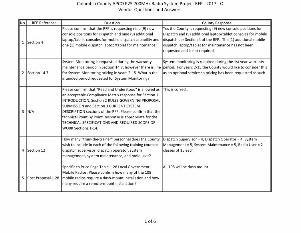
No. RFP Reference Question County Response
1 Section 4
Please confirm that the RFP is requesting nine (9) new console positions for Dispatch and nine (9) additional laptop/tablet consoles for mobile dispatch capability and one (1) mobile dispatch laptop/tablet for maintenance.
Yes the County is requesting (9) new console positions for Dispatch and (9) additional laptop/tablet consoles for mobile dispatch per Section 4 of the RFP. The (1) additional mobile dispatch laptop/tablet for maintenance has not been requested and is not required.
2 Section 14.7
System Monitoring is requested during the warranty maintenance period in Section 14.7; however there is line for System Monitoring pricing in years 2-15. What is the intended period requested for System Monitoring?
System monitoring is required during the 1st year warranty period. For years 2-15 the County would like to consider this as an optional service so pricing has been requested as such.
3 N/A
Please confirm that "Read and Understood" is allowed as an acceptable Compliance Matrix response for Section 1. INTRODUCTION, Section 2 RULES GOVERNING PROPOSAL SUBMISSION and Section 3 CURRENT SYSTEM DESCRIPTION sections of the RFP. Please confirm that the technical Point By Point Response is appropriate for the TECHNICAL SPECIFICATIONS AND REQUIRED SCOPE OF WORK Sections 1-14.
This is correct.
4 Section 12
How many "train-the-trainer" personnel does the County wish to include in each of the following training courses: dispatch supervisor, dispatch operator, system management, system maintenance, and radio user?
Dispatch Supervisor = 4, Dispatch Operator = 4, System Management = 5, System Maintenance = 5, Radio User = 2 classes of 15 each.
5 Cost Proposal 1.28
Specific to Price Page Table 1.28 Local Government Mobile Radios: Please confirm how many of the 108 mobile radios require a dash-mount installation and how many require a remote-mount installation?
All 108 will be dash mount.
Columbia County APCO P25 700MHz Radio System Project RFP - 2017 - O Vendor Questions and Answers
1 of 6
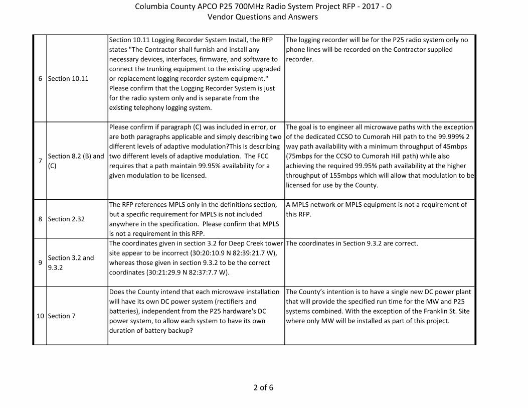
6 Section 10.11
Section 10.11 Logging Recorder System Install, the RFP states "The Contractor shall furnish and install any necessary devices, interfaces, firmware, and software to connect the trunking equipment to the existing upgraded or replacement logging recorder system equipment." Please confirm that the Logging Recorder System is just for the radio system only and is separate from the existing telephony logging system.
The logging recorder will be for the P25 radio system only no phone lines will be recorded on the Contractor supplied recorder.
7Section 8.2 (B) and (C)
Please confirm if paragraph (C) was included in error, or are both paragraphs applicable and simply describing two different levels of adaptive modulation?This is describing two different levels of adaptive modulation. The FCC requires that a path maintain 99.95% availability for a given modulation to be licensed.
The goal is to engineer all microwave paths with the exception of the dedicated CCSO to Cumorah Hill path to the 99.999% 2 way path availability with a minimum throughput of 45mbps (75mbps for the CCSO to Cumorah Hill path) while also achieving the required 99.95% path availability at the higher throughput of 155mbps which will allow that modulation to be licensed for use by the County.
8 Section 2.32
The RFP references MPLS only in the definitions section, but a specific requirement for MPLS is not included anywhere in the specification. Please confirm that MPLS is not a requirement in this RFP.
A MPLS network or MPLS equipment is not a requirement of this RFP.
9Section 3.2 and 9.3.2
The coordinates given in section 3.2 for Deep Creek tower site appear to be incorrect (30:20:10.9 N 82:39:21.7 W), whereas those given in section 9.3.2 to be the correct coordinates (30:21:29.9 N 82:37:7.7 W).
The coordinates in Section 9.3.2 are correct.
10 Section 7
Does the County intend that each microwave installation will have its own DC power system (rectifiers and batteries), independent from the P25 hardware's DC power system, to allow each system to have its own duration of battery backup?
The County’s intention is to have a single new DC power plant that will provide the specified run time for the MW and P25 systems combined. With the exception of the Franklin St. Site where only MW will be installed as part of this project.
Columbia County APCO P25 700MHz Radio System Project RFP - 2017 - O Vendor Questions and Answers
2 of 6
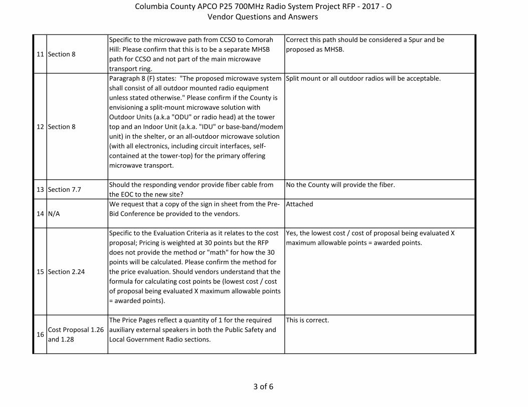
11 Section 8
Specific to the microwave path from CCSO to Comorah Hill: Please confirm that this is to be a separate MHSB path for CCSO and not part of the main microwave transport ring.
Correct this path should be considered a Spur and be proposed as MHSB.
12 Section 8
Paragraph 8 (F) states: "The proposed microwave system shall consist of all outdoor mounted radio equipment unless stated otherwise." Please confirm if the County is envisioning a split-mount microwave solution with Outdoor Units (a.k.a "ODU" or radio head) at the tower top and an Indoor Unit (a.k.a. "IDU" or base-band/modem unit) in the shelter, or an all-outdoor microwave solution (with all electronics, including circuit interfaces, self-contained at the tower-top) for the primary offering microwave transport.
Split mount or all outdoor radios will be acceptable.
13 Section 7.7Should the responding vendor provide fiber cable from the EOC to the new site?
No the County will provide the fiber.
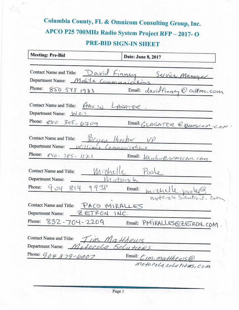
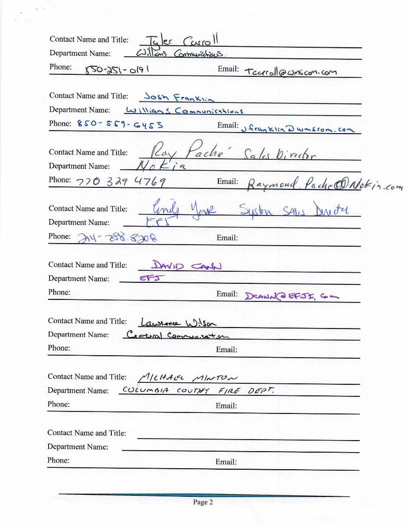
14 N/AWe request that a copy of the sign in sheet from the Pre-Bid Conference be provided to the vendors.
Attached
15 Section 2.24
Specific to the Evaluation Criteria as it relates to the cost proposal; Pricing is weighted at 30 points but the RFP does not provide the method or "math" for how the 30 points will be calculated. Please confirm the method for the price evaluation. Should vendors understand that the formula for calculating cost points be (lowest cost / cost of proposal being evaluated X maximum allowable points = awarded points).
Yes, the lowest cost / cost of proposal being evaluated X maximum allowable points = awarded points.
16Cost Proposal 1.26 and 1.28
The Price Pages reflect a quantity of 1 for the required auxiliary external speakers in both the Public Safety and Local Government Radio sections.
This is correct.
Columbia County APCO P25 700MHz Radio System Project RFP - 2017 - O Vendor Questions and Answers
3 of 6
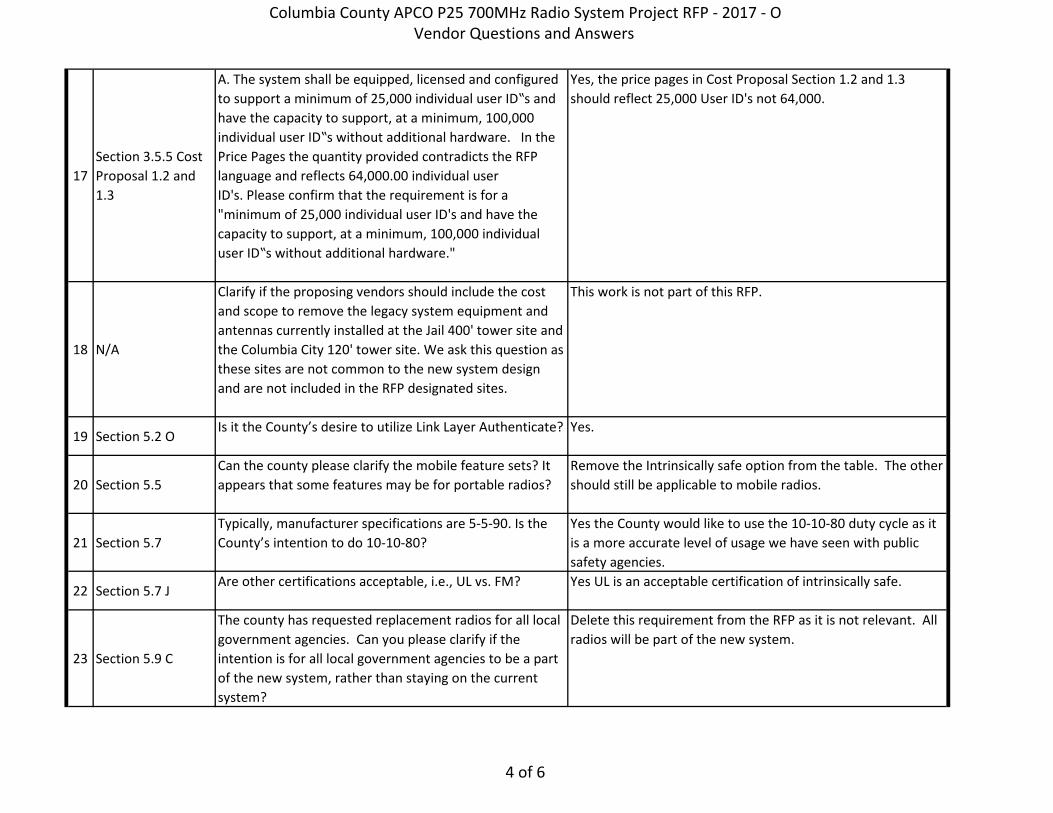
17Section 3.5.5 Cost Proposal 1.2 and 1.3
A. The system shall be equipped, licensed and configured to support a minimum of 25,000 individual user ID‟s and have the capacity to support, at a minimum, 100,000 individual user ID‟s without additional hardware. In the Price Pages the quantity provided contradicts the RFP language and reflects 64,000.00 individual user ID's. Please confirm that the requirement is for a "minimum of 25,000 individual user ID's and have the capacity to support, at a minimum, 100,000 individual user ID‟s without additional hardware."
Yes, the price pages in Cost Proposal Section 1.2 and 1.3 should reflect 25,000 User ID's not 64,000.
18 N/A
Clarify if the proposing vendors should include the cost and scope to remove the legacy system equipment and antennas currently installed at the Jail 400' tower site and the Columbia City 120' tower site. We ask this question as these sites are not common to the new system design and are not included in the RFP designated sites.
This work is not part of this RFP.
19 Section 5.2 OIs it the County’s desire to utilize Link Layer Authenticate? Yes.
20 Section 5.5Can the county please clarify the mobile feature sets? It appears that some features may be for portable radios?
Remove the Intrinsically safe option from the table. The other should still be applicable to mobile radios.
21 Section 5.7Typically, manufacturer specifications are 5-5-90. Is the County’s intention to do 10-10-80?
Yes the County would like to use the 10-10-80 duty cycle as it is a more accurate level of usage we have seen with public safety agencies.
22 Section 5.7 JAre other certifications acceptable, i.e., UL vs. FM? Yes UL is an acceptable certification of intrinsically safe.
23 Section 5.9 C
The county has requested replacement radios for all local government agencies. Can you please clarify if the intention is for all local government agencies to be a part of the new system, rather than staying on the current system?
Delete this requirement from the RFP as it is not relevant. All radios will be part of the new system.
Columbia County APCO P25 700MHz Radio System Project RFP - 2017 - O Vendor Questions and Answers
4 of 6
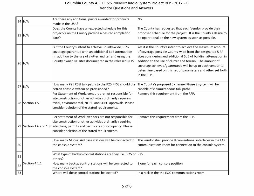
24 N/AAre there any additional points awarded for products made in the USA?
No
25 N/A
Does the County have an expected schedule for this project? Can the County provide a desired completion date?
The County has requested that each Vendor provide their proposed schedule for the project. It is the County’s desire to be operational on the new system as soon as possible.
26 N/A
Is it the County’s intent to achieve County-wide, 95% coverage guarantee with an additional 6dB attenuation (in addition to the use of clutter and terrain) using the County owned RF sites documented in the released RFP?
Yes it is the County’s intent to achieve the maximum amount of coverage possible County-wide from the designated 5 RF sites considering and additional 6dB of building attenuation in addition to the use of clutter and terrain. The amount of coverage achieved/guarenteed will be up to each vendor to determine based on this set of parameters and other set forth in the RFP.
27 N/AHow many P25 CSSI talk paths to the P25 RFSS should the Zetron console system be previsioned?
The County’s proposed 5 channel Phase 2 system will be capable of 8 simultaneous talk paths.
28 Section 1.5
Per Statement of Work, vendors are not responsible for site construction or other activities ordinarily requiring tribal, environmental, NEPA, and SHPO approvals. Please consider deletion of the stated requirements.
Remove this requirement from the RFP.
29 Section 1.6 and 1.8
Per statement of Work, vendors are not responsible for site construction or other activities ordinarily requiring site plans, permits and certificates of occupancy. Please consider deletion of the stated requirements.
Remove this requirement from the RFP.
30How many Mutual Aid base stations will be connected to the console system?
The vendor shall provide 8 conventional interfaces in the EOC communications room for connection to the console system.
31What type of backup control stations are they, i.e., P25 or others?
P25.
32How many backup control stations will be connected to the console system?
9 one for each console position.
33 Where will these control stations be located? In a rack in the the EOC communications room.
Section 4.1.1
Columbia County APCO P25 700MHz Radio System Project RFP - 2017 - O Vendor Questions and Answers
5 of 6
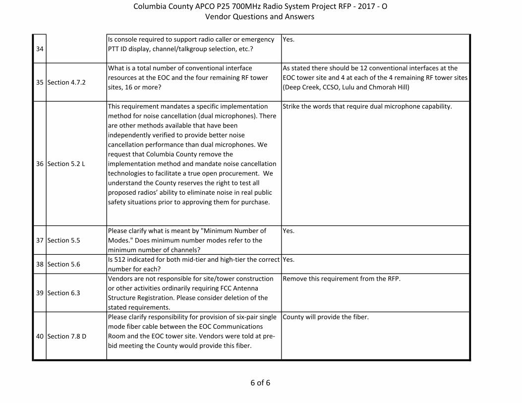
34Is console required to support radio caller or emergency PTT ID display, channel/talkgroup selection, etc.?
Yes.
35 Section 4.7.2
What is a total number of conventional interface resources at the EOC and the four remaining RF tower sites, 16 or more?
As stated there should be 12 conventional interfaces at the EOC tower site and 4 at each of the 4 remaining RF tower sites (Deep Creek, CCSO, Lulu and Chmorah Hill)
36 Section 5.2 L
This requirement mandates a specific implementation method for noise cancellation (dual microphones). There are other methods available that have been independently verified to provide better noise cancellation performance than dual microphones. We request that Columbia County remove the implementation method and mandate noise cancellation technologies to facilitate a true open procurement. We understand the County reserves the right to test all proposed radios’ ability to eliminate noise in real public safety situations prior to approving them for purchase.
Strike the words that require dual microphone capability.
37 Section 5.5Please clarify what is meant by "Minimum Number of Modes." Does minimum number modes refer to the minimum number of channels?
Yes.
38 Section 5.6Is 512 indicated for both mid-tier and high-tier the correct number for each?
Yes.
39 Section 6.3
Vendors are not responsible for site/tower construction or other activities ordinarily requiring FCC Antenna Structure Registration. Please consider deletion of the stated requirements.
Remove this requirement from the RFP.
40 Section 7.8 D
Please clarify responsibility for provision of six-pair single mode fiber cable between the EOC Communications Room and the EOC tower site. Vendors were told at pre-bid meeting the County would provide this fiber.
County will provide the fiber.
Columbia County APCO P25 700MHz Radio System Project RFP - 2017 - O Vendor Questions and Answers
6 of 6

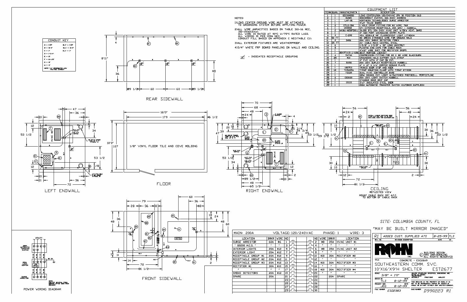
Columbia County APCO P25 700MHz Radio System Project RFP - 2017 - O
Vendor Questions and Answers
Franklin St. Tower Additional Information
Revision # Date Issued Description
0 October 30, 2013 Original structural analysis (TEP#26513_10345)
1 December 13, 2013 Revised Central Communications loading
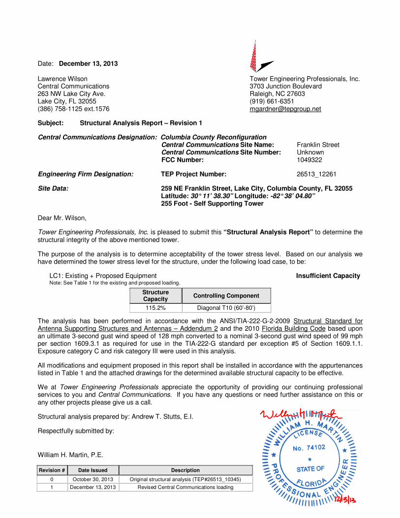
Date: December 13, 2013 Lawrence Wilson Tower Engineering Professionals, Inc. Central Communications 3703 Junction Boulevard 263 NW Lake City Ave. Raleigh, NC 27603 Lake City, FL 32055 (919) 661-6351 (386) 758-1125 ext.1576 [email protected]
Subject: Structural Analysis Report – Revision 1
Central Communications Designation: Columbia County Reconfiguration Central Communications Site Name: Franklin Street Central Communications Site Number: Unknown FCC Number: 1049322
Engineering Firm Designation: TEP Project Number: 26513_12261
Site Data: 259 NE Franklin Street, Lake City, Columbia County, FL 32055 Latitude: 30° 11’ 38.30” Longitude: -82° 38’ 04.80” 255 Foot - Self Supporting Tower
Dear Mr. Wilson,
Tower Engineering Professionals, Inc. is pleased to submit this “Structural Analysis Report” to determine the structural integrity of the above mentioned tower.
The purpose of the analysis is to determine acceptability of the tower stress level. Based on our analysis we have determined the tower stress level for the structure, under the following load case, to be:
LC1: Existing + Proposed Equipment Insufficient Capacity Note: See Table 1 for the existing and proposed loading.
The analysis has been performed in accordance with the ANSI/TIA-222-G-2-2009 Structural Standard for Antenna Supporting Structures and Antennas – Addendum 2 and the 2010 Florida Building Code based upon an ultimate 3-second gust wind speed of 128 mph converted to a nominal 3-second gust wind speed of 99 mph per section 1609.3.1 as required for use in the TIA-222-G standard per exception #5 of Section 1609.1.1. Exposure category C and risk category III were used in this analysis.
All modifications and equipment proposed in this report shall be installed in accordance with the appurtenances listed in Table 1 and the attached drawings for the determined available structural capacity to be effective.
We at Tower Engineering Professionals appreciate the opportunity of providing our continuing professional services to you and Central Communications. If you have any questions or need further assistance on this or any other projects please give us a call.
Structural analysis prepared by: Andrew T. Stutts, E.I.
Respectfully submitted by: William H. Martin, P.E.
Structure Capacity
Controlling Component
115.2% Diagonal T10 (60’-80’)
December 13, 2013 255-ft Self Supporting Tower Structural Analysis Franklin Street TEP Project Number 26513_12261, Revision 1 Page 2
tnxTower Report - version 6.1.3.1
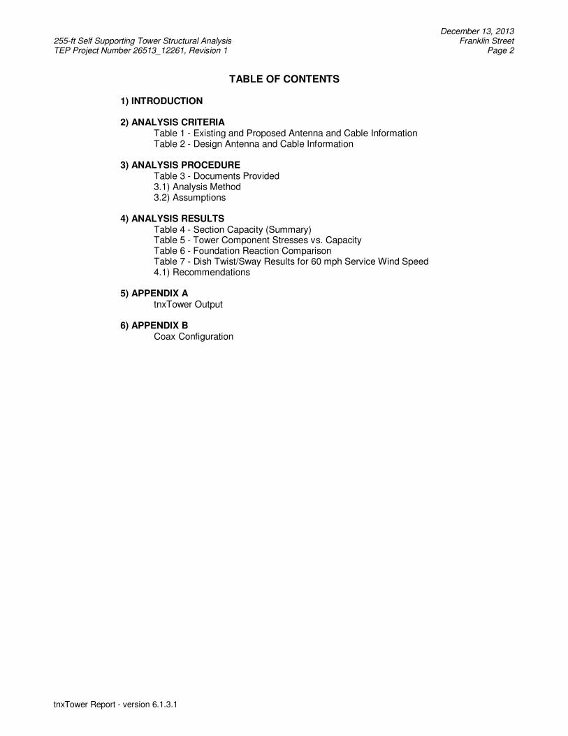
TABLE OF CONTENTS 1) INTRODUCTION 2) ANALYSIS CRITERIA Table 1 - Existing and Proposed Antenna and Cable Information Table 2 - Design Antenna and Cable Information 3) ANALYSIS PROCEDURE Table 3 - Documents Provided 3.1) Analysis Method 3.2) Assumptions 4) ANALYSIS RESULTS Table 4 - Section Capacity (Summary) Table 5 - Tower Component Stresses vs. Capacity Table 6 - Foundation Reaction Comparison
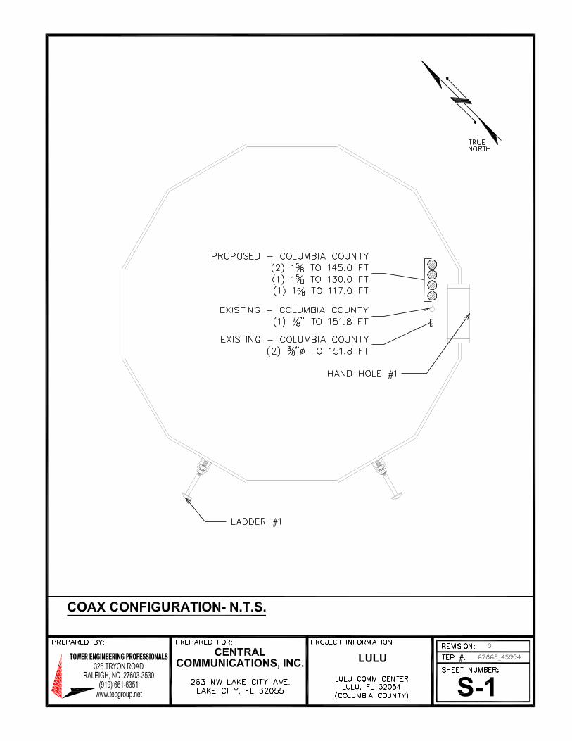
Table 7 - Dish Twist/Sway Results for 60 mph Service Wind Speed 4.1) Recommendations 5) APPENDIX A tnxTower Output 6) APPENDIX B Coax Configuration
December 13, 2013 255-ft Self Supporting Tower Structural Analysis Franklin Street TEP Project Number 26513_12261, Revision 1 Page 3
tnxTower Report - version 6.1.3.1
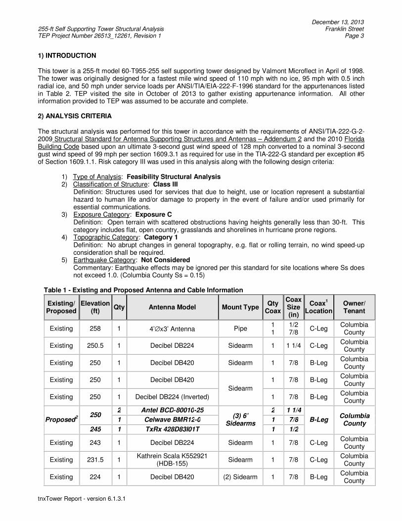
1) INTRODUCTION This tower is a 255-ft model 60-T955-255 self supporting tower designed by Valmont Microflect in April of 1998. The tower was originally designed for a fastest mile wind speed of 110 mph with no ice, 95 mph with 0.5 inch radial ice, and 50 mph under service loads per ANSI/TIA/EIA-222-F-1996 standard for the appurtenances listed in Table 2. TEP visited the site in October of 2013 to gather existing appurtenance information. All other information provided to TEP was assumed to be accurate and complete. 2) ANALYSIS CRITERIA The structural analysis was performed for this tower in accordance with the requirements of ANSI/TIA-222-G-2-2009 Structural Standard for Antenna Supporting Structures and Antennas – Addendum 2 and the 2010 Florida Building Code based upon an ultimate 3-second gust wind speed of 128 mph converted to a nominal 3-second gust wind speed of 99 mph per section 1609.3.1 as required for use in the TIA-222-G standard per exception #5 of Section 1609.1.1. Risk category III was used in this analysis along with the following design criteria:
1) Type of Analysis: Feasibility Structural Analysis 2) Classification of Structure: Class III Definition: Structures used for services that due to height, use or location represent a substantial
hazard to human life and/or damage to property in the event of failure and/or used primarily for essential communications.
3) Exposure Category: Exposure C Definition: Open terrain with scattered obstructions having heights generally less than 30-ft. This category includes flat, open country, grasslands and shorelines in hurricane prone regions.
4) Topographic Category: Category 1 Definition: No abrupt changes in general topography, e.g. flat or rolling terrain, no wind speed-up
consideration shall be required. 5) Earthquake Category: Not Considered
Commentary: Earthquake effects may be ignored per this standard for site locations where Ss does not exceed 1.0. (Columbia County Ss = 0.15)
Table 1 - Existing and Proposed Antenna and Cable Information
Existing/ Proposed
Elevation (ft)
Qty Antenna Model Mount Type Qty
Coax
Coax Size (in)
Coax1
Location
Owner/ Tenant
Existing 258 1 4’∅x3’ Antenna Pipe 1 1
1/2 7/8
C-Leg Columbia County
Existing 250.5 1 Decibel DB224 Sidearm 1 1 1/4 C-Leg Columbia County
Existing 250 1 Decibel DB420 Sidearm 1 7/8 B-Leg Columbia County
Existing 250 1 Decibel DB420
Sidearm
1 7/8 B-Leg Columbia County
Existing 250 1 Decibel DB224 (Inverted) 1 7/8 B-Leg Columbia County
Proposed2 250
2 Antel BCD-80010-25 (3) 6’
Sidearms
2 1 1/4
B-Leg Columbia County
1 Celwave BMR12-0 1 7/8
245 1 TxRx 428D83I01T 1 1/2
Existing 243 1 Decibel DB224 Sidearm 1 7/8 C-Leg Columbia County
Existing 231.5 1 Kathrein Scala K552921
(HDB-155) Sidearm 1 7/8 C-Leg
Columbia County
Existing 224 1 Decibel DB420 (2) Sidearm 1 7/8 B-Leg Columbia County
December 13, 2013 255-ft Self Supporting Tower Structural Analysis Franklin Street TEP Project Number 26513_12261, Revision 1 Page 4
tnxTower Report - version 6.1.3.1
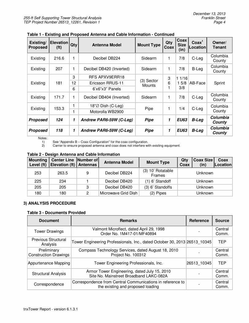
Table 1 - Existing and Proposed Antenna and Cable Information - Continued
Existing/ Proposed
Elevation (ft)
Qty Antenna Model Mount Type Qty
Coax
Coax Size (in)
Coax1
Location
Owner/ Tenant
Existing 216.6 1 Decibel DB224 Sidearm 1 7/8 C-Leg Columbia County
Existing 207 1 Decibel DB420 (Inverted) Sidearm 1 7/8 B-Leg Columbia County
Existing 181
3 RFS APXV9ERR18 (3) Sector Mounts
3 6 1
1 1/16 1 5/8 3/8
AB-Face Sprint 12 Ericsson RRUS-11
6 6’x6”x3” Panels
Existing 171.7 1 Decibel DB404 (Inverted) Sidearm 1 7/8 C-Leg Columbia County
Existing 153.3 1 18”∅ Dish (C-Leg)
Pipe 1 1/4 C-Leg Columbia County 1 Motorolla WB2900
Proposed 124 1 Andrew PAR6-59W (C-Leg) Pipe 1 EU63 B-Leg Columbia County
Proposed 118 1 Andrew PAR6-59W (C-Leg) Pipe 1 EU63 B-Leg Columbia County
Notes: 1) See “Appendix B – Coax Configuration” for the coax configuration. 2) Carrier to ensure proposed antenna and coax does not interfere with existing equipment.
Table 2 - Design Antenna and Cable Information
Mounting Level (ft)
Center Line Elevation (ft)
Number of Antennas
Antenna Model Mount Type Qty
Coax Coax Size
(in) Coax
Location
253 263.5 9 Decibel DB224 (3) 10’ Rotatable
Frames Unknown
225 234 1 Decibel DB420 (1) 6’ Standoff Unknown
205 205 3 Decibel DB420 (3) 6’ Standoffs Unknown
180 180 2 Microwave Grid Dish (2) Pipes Unknown
3) ANALYSIS PROCEDURE
Table 3 - Documents Provided
Document Remarks Reference Source
Tower Drawings Valmont Microflect, dated April 29, 1998
Order No. 1M417-01/MF40894 -
Central Comm.
Previous Structural Analysis
Tower Engineering Professionals, Inc., dated October 30, 2013 26513_10345 TEP
Preliminary Construction Drawings
Compass Technology Services, dated August 18, 2010 Project No. 100312
- Central Comm.
Appurtenance Mapping Tower Engineering Professionals, Inc. 26513_10345 TEP
Structural Analysis Armor Tower Engineering, dated July 15, 2010
Site No. Mainstreet Broadband LAKC-082A -
Central Comm.
Correspondence Correspondence from Central Communications in reference to
the existing and proposed loading -
Central Comm.
December 13, 2013 255-ft Self Supporting Tower Structural Analysis Franklin Street TEP Project Number 26513_12261, Revision 1 Page 5
tnxTower Report - version 6.1.3.1
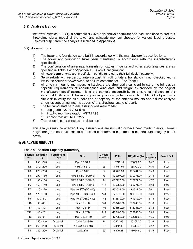
3.1) Analysis Method
tnxTower (version 6.1.3.1), a commercially available analysis software package, was used to create a three-dimensional model of the tower and calculate member stresses for various loading cases. Selected output from the analysis is included in Appendix A.
3.2) Assumptions
1) The tower and foundation were built in accordance with the manufacturer’s specifications. 2) The tower and foundation have been maintained in accordance with the manufacturer’s
specification. 3) The configuration of antennas, transmission cables, mounts and other appurtenances are as
specified in Table 1 and “Appendix B – Coax Configuration”. 4) All tower components are in sufficient condition to carry their full design capacity. 5) Serviceability with respect to antenna twist, tilt, roll, or lateral translation, is not checked and is
left to the carrier or tower owner to ensure conformance. See Table 7. 6) All antenna mounts and mounting hardware are structurally sufficient to carry the full design
capacity requirements of appurtenance wind area and weight as provided by the original manufacturer specifications. It is the carrier’s responsibility to ensure compliance to the structural limitations of the existing and/or proposed antenna mounts. TEP did not perform a site visit to verify the size, condition or capacity of the antenna mounts and did not analyze antennas supporting mounts as part of this structural analysis report.
7) The following material grade assumptions were made: a) Leg grade: ASTM A53-B-46 b) Bracing members grade: ASTM A36 c) Anchor rod: ASTM A572-50
8) This report is not a construction document.
This analysis may be affected if any assumptions are not valid or have been made in error. Tower Engineering Professionals should be notified to determine the effect on the structural integrity of the tower.
4) ANALYSIS RESULTS
Table 4 - Section Capacity (Summary)
Section No.
Elevation (ft)
Component Type Size Critical
Element P (lb) ∅∅∅∅P_allow (lb) % Capacity Pass / Fail
T1 255 - 240 Leg Pipe 2.5 STD 1 -12742.10 53865.90 23.7 Pass
T2 240 - 220 Leg PIPE 3.5 STD 25 -44551.60 96872.30 46.0 Pass
T3 220 - 200 Leg Pipe 5 STD 52 -88058.30 157444.00 55.9 Pass
T4 200 - 180 Leg PIPE 8 STD (SCH40) 73 -120397.00 330771.00 36.4 Pass
T5 180 - 160 Leg PIPE 8 STD (SCH40) 94 -157923.00 330771.00 47.7 Pass
T6 160 - 140 Leg PIPE 8 STD (SCH40) 115 -196255.00 330771.00 59.3 Pass
T7 140 - 120 Leg Pipe 10 STD (SCH40) 136 -231031.00 461312.00 50.1 Pass
T8 120 - 100 Leg Pipe 10 STD (SCH40) 151 -271670.00 461312.00 58.9 Pass
T9 100 - 80 Leg Pipe 10 STD (SCH40) 166 -312679.00 461312.00 67.8 Pass
T10 80 - 60 Leg Pipe 12 STD 181 -353403.00 573746.00 61.6 Pass
T11 60 - 40 Leg Pipe 12 STD 196 -394550.00 573746.00 68.8 Pass
T12 40 - 20 Leg Pipe 12 STD 212 -435406.00 573746.00 75.9 Pass
T13 20 - 0 Leg Pipe 12 SCH 80 227 -477259.00 1026190.00 46.5 Pass
T1 255 - 240 Diagonal L1 3/4x1 3/4x3/16 11 -3222.66 10205.20 31.6 Pass
T2 240 - 220 Diagonal L1 3/4x1 3/4x3/16 38 -4452.03 10417.70 42.7 Pass
T3 220 - 200 Diagonal L2x2x3/16 59 -6979.21 11924.80 58.5 Pass
December 13, 2013 255-ft Self Supporting Tower Structural Analysis Franklin Street TEP Project Number 26513_12261, Revision 1 Page 6
tnxTower Report - version 6.1.3.1
Section No.
Elevation (ft)
Component Type Size Critical
Element P (lb) ∅∅∅∅P_allow (lb) %
Capacity Pass / Fail
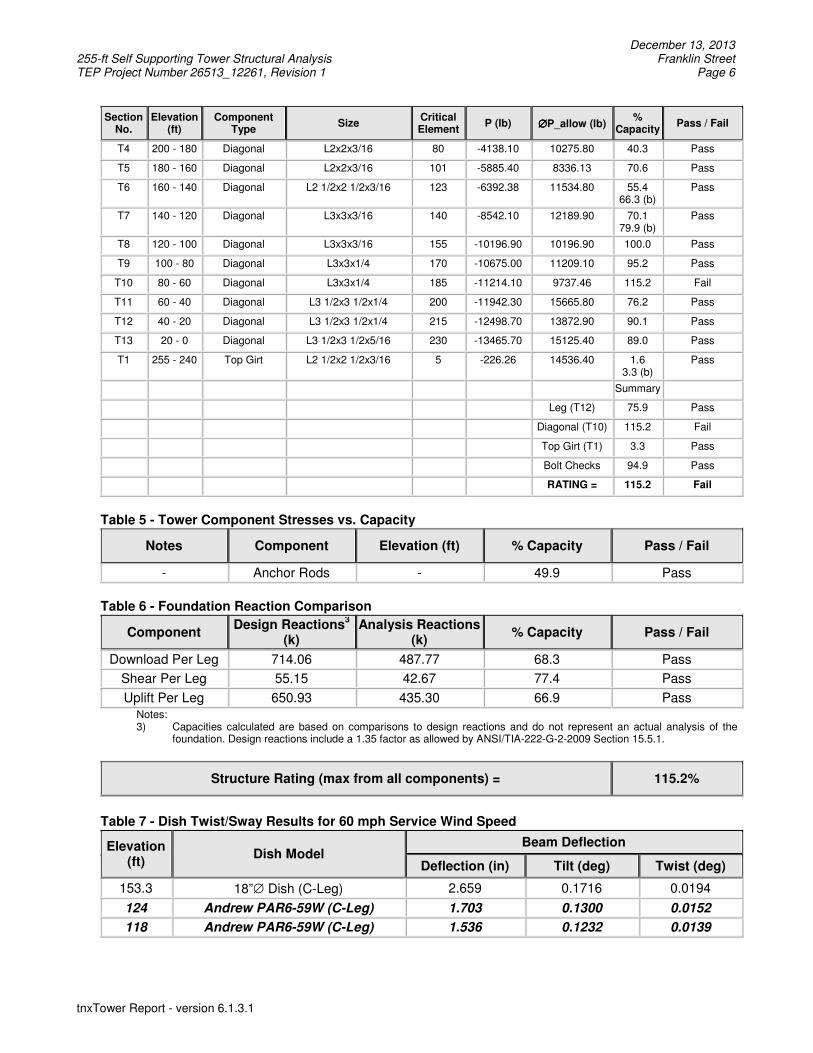
T4 200 - 180 Diagonal L2x2x3/16 80 -4138.10 10275.80 40.3 Pass
T5 180 - 160 Diagonal L2x2x3/16 101 -5885.40 8336.13 70.6 Pass
T6 160 - 140 Diagonal L2 1/2x2 1/2x3/16 123 -6392.38 11534.80 55.4 66.3 (b)
Pass
T7 140 - 120 Diagonal L3x3x3/16 140 -8542.10 12189.90 70.1 79.9 (b)
Pass
T8 120 - 100 Diagonal L3x3x3/16 155 -10196.90 10196.90 100.0 Pass
T9 100 - 80 Diagonal L3x3x1/4 170 -10675.00 11209.10 95.2 Pass
T10 80 - 60 Diagonal L3x3x1/4 185 -11214.10 9737.46 115.2 Fail
T11 60 - 40 Diagonal L3 1/2x3 1/2x1/4 200 -11942.30 15665.80 76.2 Pass
T12 40 - 20 Diagonal L3 1/2x3 1/2x1/4 215 -12498.70 13872.90 90.1 Pass
T13 20 - 0 Diagonal L3 1/2x3 1/2x5/16 230 -13465.70 15125.40 89.0 Pass
T1 255 - 240 Top Girt L2 1/2x2 1/2x3/16 5 -226.26 14536.40 1.6 3.3 (b)
Pass
Summary
Leg (T12) 75.9 Pass
Diagonal (T10) 115.2 Fail
Top Girt (T1) 3.3 Pass
Bolt Checks 94.9 Pass
RATING = 115.2 Fail
Table 5 - Tower Component Stresses vs. Capacity
Notes Component Elevation (ft) % Capacity Pass / Fail
- Anchor Rods - 49.9 Pass
Table 6 - Foundation Reaction Comparison
Component Design Reactions
3
(k) Analysis Reactions
(k) % Capacity Pass / Fail
Download Per Leg 714.06 487.77 68.3 Pass
Shear Per Leg 55.15 42.67 77.4 Pass
Uplift Per Leg 650.93 435.30 66.9 Pass
Notes: 3) Capacities calculated are based on comparisons to design reactions and do not represent an actual analysis of the
foundation. Design reactions include a 1.35 factor as allowed by ANSI/TIA-222-G-2-2009 Section 15.5.1.
Structure Rating (max from all components) = 115.2%
Table 7 - Dish Twist/Sway Results for 60 mph Service Wind Speed
Elevation (ft)
Dish Model Beam Deflection
Deflection (in) Tilt (deg) Twist (deg)
153.3 18”∅ Dish (C-Leg) 2.659 0.1716 0.0194
124 Andrew PAR6-59W (C-Leg) 1.703 0.1300 0.0152
118 Andrew PAR6-59W (C-Leg) 1.536 0.1232 0.0139
December 13, 2013 255-ft Self Supporting Tower Structural Analysis Franklin Street TEP Project Number 26513_12261, Revision 1 Page 7
tnxTower Report - version 6.1.3.1
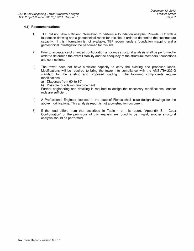
4.1) Recommendations
1) TEP did not have sufficient information to perform a foundation analysis. Provide TEP with a foundation drawing and a geotechnical report for this site in order to determine the substructure capacity. If this information is not available, TEP recommends a foundation mapping and a geotechnical investigation be performed for this site.
2) Prior to acceptance of changed configuration a rigorous structural analysis shall be performed in
order to determine the overall stability and the adequacy of the structural members, foundations and connections.
3) The tower does not have sufficient capacity to carry the existing and proposed loads.
Modifications will be required to bring the tower into compliance with the ANSI/TIA-222-G standard for the existing and proposed loading. The following components require modifications: a) Diagonals from 60’ to 80’ b) Possible foundation reinforcement. Further engineering and detailing is required to design the necessary modifications. Anchor rods are sufficient.
4) A Professional Engineer licensed in the state of Florida shall issue design drawings for the above modifications. This analysis report is not a construction document.
5) If the load differs from that described in Table 1 of this report, “Appendix B – Coax Configuration” or the provisions of this analysis are found to be invalid, another structural analysis should be performed.
December 13, 2013 255-ft Self Supporting Tower Structural Analysis Franklin Street TEP Project Number 26513_12261, Revision 1 Page 8
tnxTower Report - version 6.1.3.1
APPENDIX A
TNXTOWER OUTPUT
Tower Engineering Professionals
Tower Engineering Professionals 3703 Junction Blvd.
Raleigh, NC 27603 Phone: (919) 661-6351
FAX: (919) 661-6350
Job: Franklin Street
Project: TEP# 26513_12261, Revision 1 Client: Central Communications Drawn by: Rebecca H. Lalor, E.I. App'd:
Code: TIA-222-G Date: 12/13/13 Scale: NTS Path:
T:\26513\12261_Franklin Street\Structural\Rev 1\tnx\Franklin Street.eri Dwg No. E-1
255.0 ft
240.0 ft
220.0 ft
200.0 ft
180.0 ft
160.0 ft
140.0 ft
120.0 ft
100.0 ft
80.0 ft
60.0 ft
40.0 ft
20.0 ft
0.0 ft
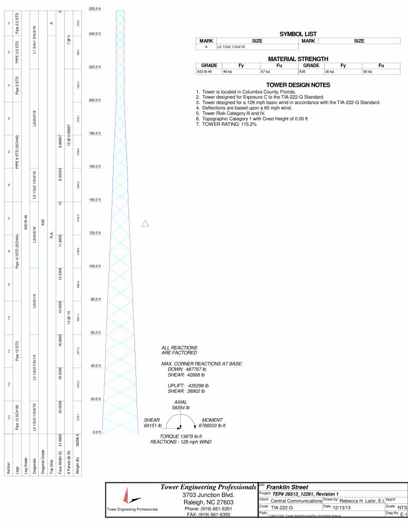
REACTIONS - 128 mph WINDTORQUE 13879 lb-ft
69151 lbSHEAR
8788503 lb-ftMOMENT
58354 lbAXIAL
SHEAR: 38902 lbUPLIFT: -435298 lb
SHEAR: 42668 lbDOWN: 487767 lb
MAX. CORNER REACTIONS AT BASE:
ARE FACTOREDALL REACTIONS
S
ection
T1
T2
T3
T4
T5
T6
T7
T8
T9
T10
T11
T12
T13
Legs
Pip
e 2
.5 S
TD
PIP
E 3
.5 S
TD
Pip
e 5
ST
DP
IPE
8 S
TD
(S
CH
40)
Pip
e 1
0 S
TD
(S
CH
40)
Pip
e 1
2 S
TD
Pip
e 1
2 S
CH
80
Leg G
rade
A53-B
-46
D
iagonals
L1 3
/4x1 3
/4x3/1
6L2x2x3/1
6L2 1
/2x2 1
/2x3/1
6L3x3x3/1
6L3x3x1/4
L3 1
/2x3 1
/2x1/4
L3 1
/2x3 1
/2x5/1
6
D
iagonal G
rade
A36
T
op G
irts
AN
.A.
F
ace W
idth
(ft)
56.6
6667
8.3
3333
10
11.6
693
13.3
359
15.0
026
16.6
693
18.3
359
20.0
026
21.6
693
# P
anels
@ (
ft)
7 @
512 @
6.6
6667
14 @
10
W
eig
ht (lb)
576.0
905.7
1242.3
2105.1
2156.5
2343.3
3102.3
3158.6
3465.8
4081.4
4371.2
4472.2
7316.1
39296.5
SYMBOL LISTMARK MARKSIZE SIZE
A L2 1/2x2 1/2x3/16
MATERIAL STRENGTHGRADE GRADEFy FyFu Fu
A53-B-46 46 ksi 67 ksi A36 36 ksi 58 ksi
TOWER DESIGN NOTES1. Tower is located in Columbia County, Florida.2. Tower designed for Exposure C to the TIA-222-G Standard.3. Tower designed for a 128 mph basic wind in accordance with the TIA-222-G Standard.4. Deflections are based upon a 60 mph wind.5. Tower Risk Category III and IV.6. Topographic Category 1 with Crest Height of 0.00 ft7. TOWER RATING: 115.2%
ttnnxxTToowweerr Job
Franklin Street
Page
1 of 29
Tower Engineering
Professionals
3703 Junction Blvd.
Project
TEP# 26513_12261, Revision 1
Date
13:49:19 12/13/13
Raleigh, NC 27603
Phone: (919) 661-6351
FAX: (919) 661-6350
Client
Central Communications Designed by
Rebecca H. Lalor, E.I.
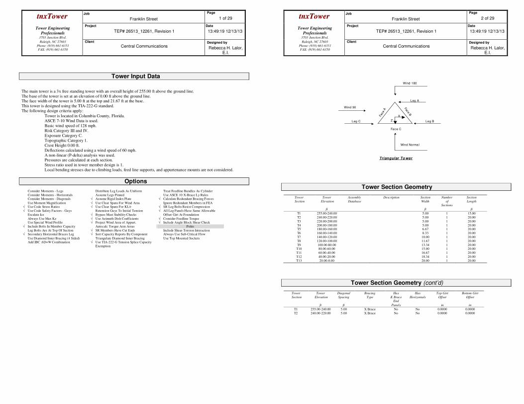
Tower Input Data
The main tower is a 3x free standing tower with an overall height of 255.00 ft above the ground line.
The base of the tower is set at an elevation of 0.00 ft above the ground line. The face width of the tower is 5.00 ft at the top and 21.67 ft at the base.
This tower is designed using the TIA-222-G standard.
The following design criteria apply:
Tower is located in Columbia County, Florida.
ASCE 7-10 Wind Data is used.
Basic wind speed of 128 mph.
Risk Category III and IV.
Exposure Category C.
Topographic Category 1.
Crest Height 0.00 ft.
Deflections calculated using a wind speed of 60 mph.
A non-linear (P-delta) analysis was used. Pressures are calculated at each section.
Stress ratio used in tower member design is 1.
Local bending stresses due to climbing loads, feed line supports, and appurtenance mounts are not considered.
Options
Consider Moments - Legs Distribute Leg Loads As Uniform Treat Feedline Bundles As Cylinder
Consider Moments - Horizontals Assume Legs Pinned Use ASCE 10 X-Brace Ly Rules Consider Moments - Diagonals √ Assume Rigid Index Plate √ Calculate Redundant Bracing Forces
Use Moment Magnification √ Use Clear Spans For Wind Area Ignore Redundant Members in FEA √ Use Code Stress Ratios √ Use Clear Spans For KL/r √ SR Leg Bolts Resist Compression
√ Use Code Safety Factors - Guys Retension Guys To Initial Tension √ All Leg Panels Have Same Allowable
Escalate Ice √ Bypass Mast Stability Checks Offset Girt At Foundation
Always Use Max Kz √ Use Azimuth Dish Coefficients √ Consider Feedline Torque Use Special Wind Profile √ Project Wind Area of Appurt. √ Include Angle Block Shear Check
√ Include Bolts In Member Capacity Autocalc Torque Arm Areas Poles
Leg Bolts Are At Top Of Section √ SR Members Have Cut Ends Include Shear-Torsion Interaction √ Secondary Horizontal Braces Leg √ Sort Capacity Reports By Component Always Use Sub-Critical Flow
Use Diamond Inner Bracing (4 Sided) Triangulate Diamond Inner Bracing Use Top Mounted Sockets Add IBC .6D+W Combination √ Use TIA-222-G Tension Splice Capacity
Exemption
ttnnxxTToowweerr Job
Franklin Street
Page
2 of 29
Tower Engineering
Professionals
3703 Junction Blvd.
Project
TEP# 26513_12261, Revision 1
Date
13:49:19 12/13/13
Raleigh, NC 27603
Phone: (919) 661-6351
FAX: (919) 661-6350
Client
Central Communications Designed by
Rebecca H. Lalor, E.I.
Leg B Leg C
Leg A
Face
A Face B
Face C
Triangular To wer
Wind Norma l
Wind 90
Wind 180
Z
X
Tower Section Geometry
Tower
Section
Tower
Elevation
ft
Assembly
Database
Description Section
Width
ft
Number
of
Sections
Section
Length
ft
T1 255.00-240.00 5.00 1 15.00
T2 240.00-220.00 5.00 1 20.00
T3 220.00-200.00 5.00 1 20.00
T4 200.00-180.00 5.00 1 20.00 T5 180.00-160.00 6.67 1 20.00
T6 160.00-140.00 8.33 1 20.00
T7 140.00-120.00 10.00 1 20.00
T8 120.00-100.00 11.67 1 20.00
T9 100.00-80.00 13.34 1 20.00 T10 80.00-60.00 15.00 1 20.00
T11 60.00-40.00 16.67 1 20.00
T12 40.00-20.00 18.34 1 20.00
T13 20.00-0.00 20.00 1 20.00
Tower Section Geometry (cont’d)
Tower
Section
Tower
Elevation
ft
Diagonal
Spacing
ft
Bracing
Type
Has
K Brace
End
Panels
Has
Horizontals
Top Girt
Offset
in
Bottom Girt
Offset
in
T1 255.00-240.00 5.00 X Brace No No 0.0000 0.0000
T2 240.00-220.00 5.00 X Brace No No 0.0000 0.0000
ttnnxxTToowweerr Job
Franklin Street
Page
3 of 29
Tower Engineering
Professionals
3703 Junction Blvd.
Project
TEP# 26513_12261, Revision 1
Date
13:49:19 12/13/13
Raleigh, NC 27603
Phone: (919) 661-6351
FAX: (919) 661-6350
Client
Central Communications Designed by
Rebecca H. Lalor, E.I.
Tower
Section
Tower
Elevation
ft
Diagonal
Spacing
ft
Bracing
Type
Has
K Brace
End
Panels
Has
Horizontals
Top Girt
Offset
in
Bottom Girt
Offset
in
T3 220.00-200.00 6.67 X Brace No No 0.0000 0.0000 T4 200.00-180.00 6.67 X Brace No No 0.0000 0.0000
T5 180.00-160.00 6.67 X Brace No No 0.0000 0.0000
T6 160.00-140.00 6.67 X Brace No No 0.0000 0.0000
T7 140.00-120.00 10.00 X Brace No No 0.0000 0.0000 T8 120.00-100.00 10.00 X Brace No No 0.0000 0.0000
T9 100.00-80.00 10.00 X Brace No No 0.0000 0.0000
T10 80.00-60.00 10.00 X Brace No No 0.0000 0.0000
T11 60.00-40.00 10.00 X Brace No No 0.0000 0.0000
T12 40.00-20.00 10.00 X Brace No No 0.0000 0.0000 T13 20.00-0.00 10.00 X Brace No No 0.0000 0.0000
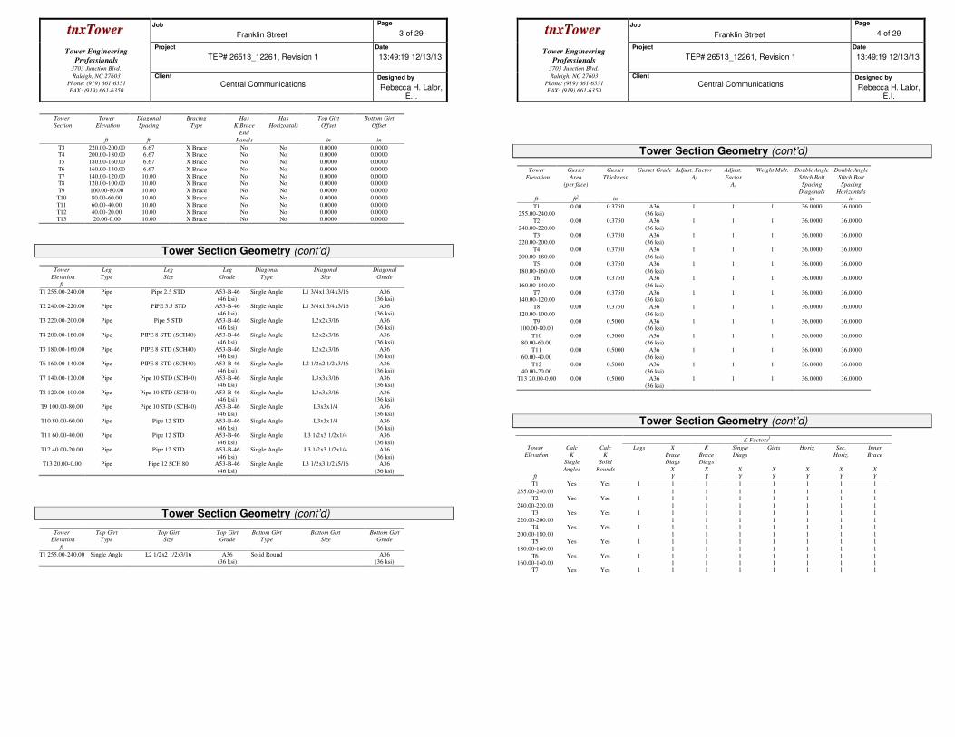
Tower Section Geometry (cont’d)
Tower
Elevation
ft
Leg
Type
Leg
Size
Leg
Grade
Diagonal
Type
Diagonal
Size
Diagonal
Grade
T1 255.00-240.00 Pipe Pipe 2.5 STD A53-B-46
(46 ksi)
Single Angle L1 3/4x1 3/4x3/16 A36
(36 ksi)
T2 240.00-220.00 Pipe PIPE 3.5 STD A53-B-46
(46 ksi)
Single Angle L1 3/4x1 3/4x3/16 A36
(36 ksi) T3 220.00-200.00 Pipe Pipe 5 STD A53-B-46
(46 ksi)
Single Angle L2x2x3/16 A36
(36 ksi)
T4 200.00-180.00 Pipe PIPE 8 STD (SCH40) A53-B-46
(46 ksi)
Single Angle L2x2x3/16 A36
(36 ksi)
T5 180.00-160.00 Pipe PIPE 8 STD (SCH40) A53-B-46 (46 ksi)
Single Angle L2x2x3/16 A36 (36 ksi)
T6 160.00-140.00 Pipe PIPE 8 STD (SCH40) A53-B-46
(46 ksi)
Single Angle L2 1/2x2 1/2x3/16 A36
(36 ksi)
T7 140.00-120.00 Pipe Pipe 10 STD (SCH40) A53-B-46 (46 ksi)
Single Angle L3x3x3/16 A36 (36 ksi)
T8 120.00-100.00 Pipe Pipe 10 STD (SCH40) A53-B-46 (46 ksi)
Single Angle L3x3x3/16 A36 (36 ksi)
T9 100.00-80.00 Pipe Pipe 10 STD (SCH40) A53-B-46
(46 ksi)
Single Angle L3x3x1/4 A36
(36 ksi) T10 80.00-60.00 Pipe Pipe 12 STD A53-B-46
(46 ksi)
Single Angle L3x3x1/4 A36
(36 ksi)
T11 60.00-40.00 Pipe Pipe 12 STD A53-B-46
(46 ksi)
Single Angle L3 1/2x3 1/2x1/4 A36
(36 ksi) T12 40.00-20.00 Pipe Pipe 12 STD A53-B-46
(46 ksi)
Single Angle L3 1/2x3 1/2x1/4 A36
(36 ksi) T13 20.00-0.00 Pipe Pipe 12 SCH 80 A53-B-46
(46 ksi)
Single Angle L3 1/2x3 1/2x5/16 A36
(36 ksi)
Tower Section Geometry (cont’d)
Tower
Elevation
ft
Top Girt
Type
Top Girt
Size
Top Girt
Grade
Bottom Girt
Type
Bottom Girt
Size
Bottom Girt
Grade
T1 255.00-240.00 Single Angle L2 1/2x2 1/2x3/16 A36
(36 ksi)
Solid Round A36
(36 ksi)
ttnnxxTToowweerr Job
Franklin Street
Page
4 of 29
Tower Engineering
Professionals
3703 Junction Blvd.
Project
TEP# 26513_12261, Revision 1
Date
13:49:19 12/13/13
Raleigh, NC 27603
Phone: (919) 661-6351
FAX: (919) 661-6350
Client
Central Communications Designed by
Rebecca H. Lalor, E.I.
Tower Section Geometry (cont’d)
Tower
Elevation
ft
Gusset
Area
(per face)
ft2
Gusset
Thickness
in
Gusset Grade Adjust. Factor
Af
Adjust.
Factor
Ar
Weight Mult.
Double Angle
Stitch Bolt
Spacing
Diagonals
in
Double Angle
Stitch Bolt
Spacing
Horizontals
in
T1
255.00-240.00
0.00 0.3750 A36
(36 ksi)
1 1 1 36.0000 36.0000
T2
240.00-220.00
0.00 0.3750 A36
(36 ksi)
1 1 1 36.0000 36.0000
T3
220.00-200.00
0.00 0.3750 A36
(36 ksi)
1 1 1 36.0000 36.0000
T4
200.00-180.00
0.00 0.3750 A36
(36 ksi)
1 1 1 36.0000 36.0000
T5
180.00-160.00
0.00 0.3750 A36
(36 ksi)
1 1 1 36.0000 36.0000
T6
160.00-140.00
0.00 0.3750 A36
(36 ksi)
1 1 1 36.0000 36.0000
T7 140.00-120.00
0.00 0.3750 A36 (36 ksi)
1 1 1 36.0000 36.0000
T8
120.00-100.00
0.00 0.3750 A36
(36 ksi)
1 1 1 36.0000 36.0000
T9 100.00-80.00
0.00 0.5000 A36 (36 ksi)
1 1 1 36.0000 36.0000
T10 80.00-60.00
0.00 0.5000 A36 (36 ksi)
1 1 1 36.0000 36.0000
T11
60.00-40.00
0.00 0.5000 A36
(36 ksi)
1 1 1 36.0000 36.0000
T12 40.00-20.00
0.00 0.5000 A36 (36 ksi)
1 1 1 36.0000 36.0000
T13 20.00-0.00 0.00 0.5000 A36
(36 ksi)
1 1 1 36.0000 36.0000
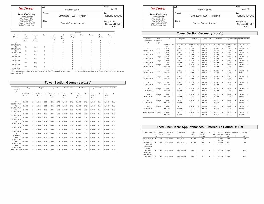
Tower Section Geometry (cont’d)
K Factors1
Tower
Elevation
ft
Calc
K
Single
Angles
Calc
K
Solid
Rounds
Legs X
Brace
Diags
X
Y
K
Brace
Diags
X
Y
Single
Diags
X
Y
Girts
X
Y
Horiz.
X
Y
Sec.
Horiz.
X
Y
Inner
Brace
X
Y
T1
255.00-240.00
Yes Yes 1 1
1
1
1
1
1
1
1
1
1
1
1
1
1 T2
240.00-220.00
Yes Yes 1 1
1
1
1
1
1
1
1
1
1
1
1
1
1
T3
220.00-200.00
Yes Yes 1 1
1
1
1
1
1
1
1
1
1
1
1
1
1 T4
200.00-180.00
Yes Yes 1 1
1
1
1
1
1
1
1
1
1
1
1
1
1
T5
180.00-160.00
Yes Yes 1 1
1
1
1
1
1
1
1
1
1
1
1
1
1
T6 160.00-140.00
Yes Yes 1 1 1
1 1
1 1
1 1
1 1
1 1
1 1
T7 Yes Yes 1 1 1 1 1 1 1 1
ttnnxxTToowweerr Job
Franklin Street
Page
5 of 29
Tower Engineering
Professionals
3703 Junction Blvd.
Project
TEP# 26513_12261, Revision 1
Date
13:49:19 12/13/13
Raleigh, NC 27603
Phone: (919) 661-6351
FAX: (919) 661-6350
Client
Central Communications Designed by
Rebecca H. Lalor, E.I.
K Factors1
Tower
Elevation
ft
Calc
K
Single
Angles
Calc
K
Solid
Rounds
Legs X
Brace
Diags
X
Y
K
Brace
Diags
X
Y
Single
Diags
X
Y
Girts
X
Y
Horiz.
X
Y
Sec.
Horiz.
X
Y
Inner
Brace
X
Y
140.00-120.00 1 1 1 1 1 1 1
T8
120.00-100.00
Yes Yes 1 1
1
1
1
1
1
1
1
1
1
1
1
1
1
T9 100.00-80.00
Yes Yes 1 1 1
1 1
1 1
1 1
1 1
1 1
1 1
T10
80.00-60.00
Yes Yes 1 1
1
1
1
1
1
1
1
1
1
1
1
1
1
T11 60.00-40.00
Yes Yes 1 1 1
1 1
1 1
1 1
1 1
1 1
1 1
T12
40.00-20.00
Yes Yes 1 1
1
1
1
1
1
1
1
1
1
1
1
1
1
T13 20.00-0.00
Yes Yes 1 1 1
1 1
1 1
1 1
1 1
1 1
1 1
1Note: K factors are applied to member segment lengths. K-braces without inner supporting members will have the K factor in the out-of-plane direction applied to
the overall length.
Tower Section Geometry (cont’d)
Tower
Elevation
ft
Leg Diagonal Top Girt Bottom Girt Mid Girt Long Horizontal Short Horizontal
Net Width
Deduct
in
U
Net Width
Deduct
in
U
Net Width
Deduct
in
U
Net
Width
Deduct
in
U
Net
Width
Deduct
in
U
Net
Width
Deduct
in
U
Net
Width
Deduct
in
U
T1 255.00-240.00
0.0000 1 0.0000 0.75 0.0000 0.75 0.0000 0.75 0.0000 0.75 0.0000 0.75 0.0000 0.75
T2 240.00-220.00
0.0000 1 0.0000 0.75 0.0000 0.75 0.0000 0.75 0.0000 0.75 0.0000 0.75 0.0000 0.75
T3 220.00-200.00
0.0000 1 0.0000 0.75 0.0000 0.75 0.0000 0.75 0.0000 0.75 0.0000 0.75 0.0000 0.75
T4 200.00-180.00
0.0000 1 0.0000 0.75 0.0000 0.75 0.0000 0.75 0.0000 0.75 0.0000 0.75 0.0000 0.75
T5
180.00-160.00
0.0000 1 0.0000 0.75 0.0000 0.75 0.0000 0.75 0.0000 0.75 0.0000 0.75 0.0000 0.75
T6
160.00-140.00
0.0000 1 0.0000 0.75 0.0000 0.75 0.0000 0.75 0.0000 0.75 0.0000 0.75 0.0000 0.75
T7
140.00-120.00
0.0000 1 0.0000 0.75 0.0000 0.75 0.0000 0.75 0.0000 0.75 0.0000 0.75 0.0000 0.75
T8
120.00-100.00
0.0000 1 0.0000 0.75 0.0000 0.75 0.0000 0.75 0.0000 0.75 0.0000 0.75 0.0000 0.75
T9
100.00-80.00
0.0000 1 0.0000 0.75 0.0000 0.75 0.0000 0.75 0.0000 0.75 0.0000 0.75 0.0000 0.75
T10
80.00-60.00
0.0000 1 0.0000 0.75 0.0000 0.75 0.0000 0.75 0.0000 0.75 0.0000 0.75 0.0000 0.75
T11
60.00-40.00
0.0000 1 0.0000 0.75 0.0000 0.75 0.0000 0.75 0.0000 0.75 0.0000 0.75 0.0000 0.75
T12 40.00-20.00
0.0000 1 0.0000 0.75 0.0000 0.75 0.0000 0.75 0.0000 0.75 0.0000 0.75 0.0000 0.75
T13 20.00-0.00 0.0000 1 0.0000 0.75 0.0000 0.75 0.0000 0.75 0.0000 0.75 0.0000 0.75 0.0000 0.75
ttnnxxTToowweerr Job
Franklin Street
Page
6 of 29
Tower Engineering
Professionals
3703 Junction Blvd.
Project
TEP# 26513_12261, Revision 1
Date
13:49:19 12/13/13
Raleigh, NC 27603
Phone: (919) 661-6351
FAX: (919) 661-6350
Client
Central Communications Designed by
Rebecca H. Lalor, E.I.
Tower Section Geometry (cont’d)
Tower
Elevation
ft
Leg
Connection
Type
Leg Diagonal Top Girt Bottom Girt Mid Girt Long Horizontal Short Horizontal
Bolt Size
in
No. Bolt Size
in
No. Bolt Size
in
No. Bolt Size
in
No. Bolt Size
in
No. Bolt Size
in
No. Bolt Size
in
No.
T1
255.00-240.00
Flange 0.7500
A325N
3 0.5000
A325X
2 0.5000
A325X
1 0.6250
A325N
0 0.6250
A325N
0 0.6250
A325N
0 0.6250
A325N
0
T2 240.00-220.00
Flange 0.8750 A325N
4 0.5000 A325X
2 0.6250 A325N
0 0.6250 A325N
0 0.6250 A325N
0 0.6250 A325N
0 0.6250 A325N
0
T3
220.00-200.00
Flange 0.8750
A325N
4 0.5000
A325X
2 0.6250
A325N
0 0.6250
A325N
0 0.6250
A325N
0 0.6250
A325N
0 0.6250
A325N
0
T4 200.00-180.00
Flange 1.0000 A325N
6 0.5000 A325X
2 0.6250 A325N
0 0.6250 A325N
0 0.6250 A325N
0 0.6250 A325N
0 0.6250 A325N
0
T5
180.00-160.00
Flange 1.5000
A325N >
1
4 0.5000
A325X
2 0.6250
A325N
0 0.6250
A325N
0 0.6250
A325N
0 0.6250
A325N
0 0.6250
A325N
0
T6 160.00-140.00
Flange 1.5000 A325N >
1
6 0.7500 A325X
1 0.6250 A325N
0 0.6250 A325N
0 0.6250 A325N
0 0.6250 A325N
0 0.6250 A325N
0
T7
140.00-120.00
Flange 1.5000
A325N > 1
6 0.7500
A325X
1 0.6250
A325N
0 0.6250
A325N
0 0.6250
A325N
0 0.6250
A325N
0 0.6250
A325N
0
T8 120.00-100.00
Flange 1.5000 A325N >
1
6 0.7500 A325X
1 0.6250 A325N
0 0.6250 A325N
0 0.6250 A325N
0 0.7500 A325N
0 0.6250 A325N
0
T9
100.00-80.00
Flange 1.5000
A325N > 1
6 0.7500
A325X
1 0.6250
A325N
0 0.6250
A325N
0 0.6250
A325N
0 0.7500
A325N
0 0.6250
A325N
0
T10
80.00-60.00
Flange 1.5000
A325N > 1
6 0.7500
A325X
1 0.6250
A325N
0 0.6250
A325N
0 0.6250
A325N
0 0.7500
A325N
0 0.6250
A325N
0
T11 60.00-40.00
Flange 1.5000 A325N >
1
6 0.6250 A325X
2 0.6250 A325N
0 0.6250 A325N
0 0.6250 A325N
0 0.7500 A325N
0 0.6250 A325N
0
T12
40.00-20.00
Flange 1.5000
A325N > 1
6 0.6250
A325X
2 0.6250
A325N
0 0.6250
A325N
0 0.6250
A325N
0 0.7500
A325N
0 0.6250
A325N
0
T13 20.00-0.00 Flange 0.0000
A325N >
1
0 0.6250
A325X
2 0.6250
A325N
0 0.6250
A325N
0 0.6250
A325N
0 0.6250
A325X
0 0.6250
A325N
0
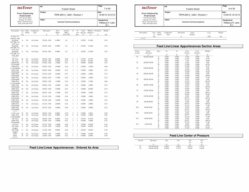
Feed Line/Linear Appurtenances - Entered As Round Or Flat
Description Face
or
Leg
Allow
Shield
Component
Type
Placement
ft
Face
Offset
in
Lateral
Offset
(Frac FW)
# #
Per
Row
Clear
Spacing
in
Width or
Diameter
in
Perimeter
in
Weight
plf
Rail L2x2x1/8 B No Af (CaAa) 182.00 - 1.33 0.0000 -0.4 2 2 34.0000 2.0000
2.0000 1.65
Rung L2 x2
x1/8 (34.25''
width w/ 48'' step)
B No Af (CaAa) 182.00 - 1.33 0.0000 -0.4 1 1 1.4270 1.4270 1.18
Rung PL
6''x1/8'' (12''
wide 60'' step)
B No Af (CaAa) 255.00 - 0.00 -7.0000 0.45 1 1 1.2000 1.2000 0.26
Rung PL C No Af (CaAa) 255.00 - 0.00 -7.0000 0.45 1 1 1.2000 1.2000 0.26
ttnnxxTToowweerr Job
Franklin Street
Page
7 of 29
Tower Engineering
Professionals
3703 Junction Blvd.
Project
TEP# 26513_12261, Revision 1
Date
13:49:19 12/13/13
Raleigh, NC 27603
Phone: (919) 661-6351
FAX: (919) 661-6350
Client
Central Communications Designed by
Rebecca H. Lalor, E.I.
Description Face
or
Leg
Allow
Shield
Component
Type
Placement
ft
Face
Offset
in
Lateral
Offset
(Frac FW)
# #
Per
Row
Clear
Spacing
in
Width or
Diameter
in
Perimeter
in
Weight
plf
6''x1/8'' (12''
wide 60'' step) Step Pegs
(5/8'' SR) 7-in.
w/30'' step
A No Ar (CaAa) 255.00 - 0.00 0.0000 0.5 1 1 0.2920 0.1460 0.24
Step Pegs (5/8'' SR) 7-in.
w/30'' step
B No Ar (CaAa) 255.00 - 0.00 0.0000 0.5 1 1 0.2920 0.1460 0.24
Step Pegs
(5/8'' SR) 7-in.
w/30'' step
C No Ar (CaAa) 255.00 - 0.00 0.0000 0.5 1 1 0.2920 0.1460 0.24
*******
3/8'' Coax B No Ar (CaAa) 255.00 - 5.00 0.0000 0.48 1 1 0.3750 0.3750 0.07
7/8'' Coax C No Ar (CaAa) 255.00 - 5.00 -8.0000 0.43 1 1 0.8750 0.8750 0.26
LDF4P-50A (1/2 FOAM)
C No Ar (CaAa) 255.00 - 5.00 -3.0000 0.47 1 1 0.5000 0.6300 0.15
LDF6-50A (1-1/4 FOAM)
C No Ar (CaAa) 250.50 - 5.00 -9.0000 0.44 1 1 0.5000 1.5500 0.66
LDF5-50A
(7/8 FOAM)
B No Ar (CaAa) 248.00 - 6.00 -8.0000 0.43 1 1 0.5000 1.0900 0.33
LDF5-50A
(7/8 FOAM)
B No Ar (CaAa) 253.00 - 6.00 -6.0000 0.47 1 1 0.5000 1.0900 0.33
LDF5-50A
(7/8 FOAM)
B No Ar (CaAa) 249.00 - 6.00 -7.5000 0.45 1 1 0.5000 1.0900 0.33
LDF6-50A
(1-1/4 FOAM)
B No Ar (CaAa) 250.00 - 5.00 -7.0000 0.44 2 2 0.5000 1.5500 0.66
LDF5-50A
(7/8 FOAM)
B No Ar (CaAa) 250.00 - 5.00 -6.0000 0.48 1 1 0.5000 1.0900 0.33
LDF4-50A
(1/2 FOAM)
B No Ar (CaAa) 245.00 - 5.00 -9.0000 0.43 1 1 0.5000 0.6300 0.15
LDF5-50A
(7/8 FOAM)
C No Ar (CaAa) 240.50 - 5.00 -7.5000 0.45 1 1 0.5000 1.0900 0.33
LDF5-50A
(7/8 FOAM)
C No Ar (CaAa) 231.50 - 5.00 -7.0000 0.44 1 1 0.5000 1.0900 0.33
LDF5-50A (7/8 FOAM)
B No Ar (CaAa) 227.00 - 6.00 -9.0000 0.48 1 1 0.5000 1.0900 0.33
LDF5-50A
(7/8 FOAM)
C No Ar (CaAa) 214.92 - 5.00 -8.0000 0.44 1 1 0.5000 1.0900 0.33
LDF5-50A (7/8 FOAM)
B No Ar (CaAa) 207.50 - 6.00 -6.0000 0.48 1 1 0.5000 1.0900 0.33
*****
1-1/16'' coax B No Ar (CaAa) 182.00 - 1.00 0.0000 -0.43 3 2 0.5000 1.0625 0.20
LDF7-50A
(1-5/8 FOAM)
B No Ar (CaAa) 182.00 - 3.00 0.0000 -0.36 6 6 0.5000 1.9800 0.82
3/8'' Coax B No Ar (CaAa) 182.00 - 3.00 0.0000 -0.32 1 1 0.3750 0.3750 0.07
LDF5-50A
(7/8 FOAM)
C No Ar (CaAa) 172.00 - 5.00 -9.0000 0.41 1 1 0.5000 1.0900 0.33
1/4 Coax C No Ar (CaAa) 153.33 - 5.00 -1.0000 0.48 1 1 0.2500 0.2500 0.10 5/8'' Cable
(Lights)
C No Ar (CaAa) 131.00 - 9.00 -5.0000 0.48 1 1 0.6250 0.6250 0.30
5/8'' Cable
(Lights)
C No Ar (CaAa) 131.00 - 9.00 0.0000 0.46 1 1 0.6250 0.6250 0.30
EU63 B No Ar (CaAa) 124.00 - 5.00 -5.0000 0.45 1 1 0.5000 2.0300 0.56
EU63 B No Ar (CaAa) 118.00 - 5.00 -4.0000 0.43 1 1 0.5000 2.0300 0.56 ******
Feed Line/Linear Appurtenances - Entered As Area
ttnnxxTToowweerr Job
Franklin Street
Page
8 of 29
Tower Engineering
Professionals
3703 Junction Blvd.
Project
TEP# 26513_12261, Revision 1
Date
13:49:19 12/13/13
Raleigh, NC 27603
Phone: (919) 661-6351
FAX: (919) 661-6350
Client
Central Communications Designed by
Rebecca H. Lalor, E.I.
Description Face
or
Leg
Allow
Shield
Component
Type
Placement
ft
Total
Number
CAAA
ft2/ft
Weight
plf
******
Feed Line/Linear Appurtenances Section Areas
Tower
Section
Tower
Elevation
ft
Face AR
ft2
AF
ft2
CAAA
In Face
ft2
CAAA
Out Face
ft2
Weight
lb
T1 255.00-240.00 A
B
C
0.000
0.000
0.000
0.000
0.000
0.000
0.219
11.557
7.159
0.000
0.000
0.000
3.66
35.76
20.80
T2 240.00-220.00 A
B C
0.000
0.000 0.000
0.000
0.000 0.000
0.292
21.985 13.836
0.000
0.000 0.000
4.88
69.59 41.87
T3 220.00-200.00 A
B
C
0.000
0.000
0.000
0.000
0.000
0.000
0.292
24.220
16.388
0.000
0.000
0.000
4.88
76.36
49.60 T4 200.00-180.00 A
B
C
0.000
0.000
0.000
0.000
0.000
0.000
0.292
30.480
16.942
0.000
0.000
0.000
4.88
100.62
51.28
T5 180.00-160.00 A
B C
0.000
0.000 0.000
0.000
0.000 0.000
0.292
74.557 18.250
0.000
0.000 0.000
4.88
281.90 55.24
T6 160.00-140.00 A
B
C
0.000
0.000
0.000
0.000
0.000
0.000
0.292
74.557
19.455
0.000
0.000
0.000
4.88
281.90
59.21 T7 140.00-120.00 A
B C
0.000
0.000 0.000
0.000
0.000 0.000
0.292
75.369 20.997
0.000
0.000 0.000
4.88
284.14 66.48
T8 120.00-100.00 A
B
C
0.000
0.000
0.000
0.000
0.000
0.000
0.292
82.271
22.122
0.000
0.000
0.000
4.88
303.18
71.88 T9 100.00-80.00 A
B
C
0.000
0.000
0.000
0.000
0.000
0.000
0.292
82.677
22.122
0.000
0.000
0.000
4.88
304.30
71.88 T10 80.00-60.00 A
B
C
0.000
0.000
0.000
0.000
0.000
0.000
0.292
82.677
22.122
0.000
0.000
0.000
4.88
304.30
71.88
T11 60.00-40.00 A B
C
0.000 0.000
0.000
0.000 0.000
0.000
0.292 82.677
22.122
0.000 0.000
0.000
4.88 304.30
71.88 T12 40.00-20.00 A
B
C
0.000
0.000
0.000
0.000
0.000
0.000
0.292
82.677
22.122
0.000
0.000
0.000
4.88
304.30
71.88
T13 20.00-0.00 A B
C
0.000 0.000
0.000
0.000 0.000
0.000
0.292 69.578
17.165
0.000 0.000
0.000
4.88 257.87
54.00
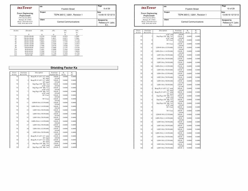
Feed Line Center of Pressure
Section Elevation
ft
CPX
in
CPZ
in
CPX
Ice
in
CPZ
Ice
in
T1 255.00-240.00 0.4607 1.8873 0.3911 2.2739
T2 240.00-220.00 0.4646 2.1210 0.4104 2.4226
ttnnxxTToowweerr Job
Franklin Street
Page
9 of 29
Tower Engineering
Professionals
3703 Junction Blvd.
Project
TEP# 26513_12261, Revision 1
Date
13:49:19 12/13/13
Raleigh, NC 27603
Phone: (919) 661-6351
FAX: (919) 661-6350
Client
Central Communications Designed by
Rebecca H. Lalor, E.I.
Section Elevation
ft
CPX
in
CPZ
in
CPX
Ice
in
CPZ
Ice
in
T3 220.00-200.00 0.3330 2.0349 0.2870 2.2909
T4 200.00-180.00 0.5061 1.4835 0.4871 1.5964 T5 180.00-160.00 0.9001 -2.0242 0.9942 -2.7728
T6 160.00-140.00 1.0063 -2.2935 1.1193 -3.1638
T7 140.00-120.00 1.0585 -2.3458 1.1840 -3.2915
T8 120.00-100.00 1.7386 -2.0778 1.8768 -3.1031 T9 100.00-80.00 2.0183 -2.2888 2.1745 -3.4330
T10 80.00-60.00 2.1601 -2.4088 2.3264 -3.6160
T11 60.00-40.00 2.3368 -2.5710 2.5159 -3.8620
T12 40.00-20.00 2.5500 -2.7748 2.7450 -4.1704
T13 20.00-0.00 2.4073 -3.6243 2.6235 -5.1297
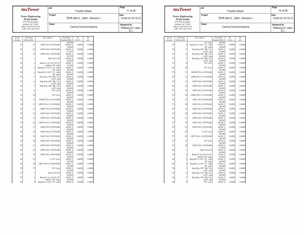
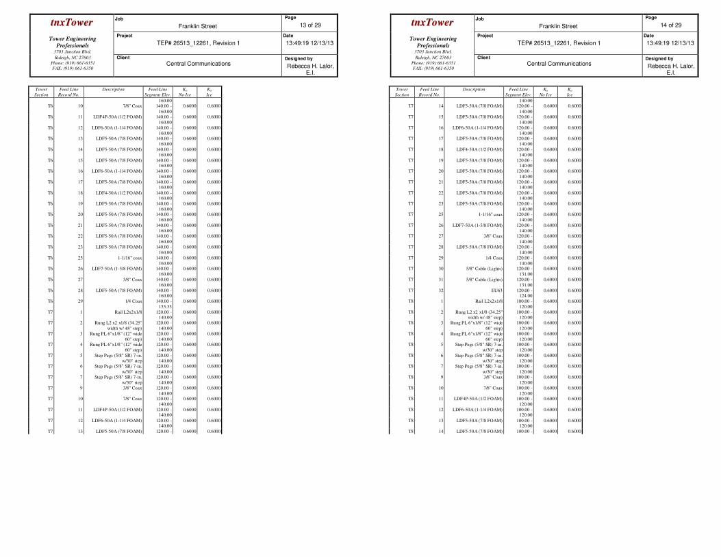
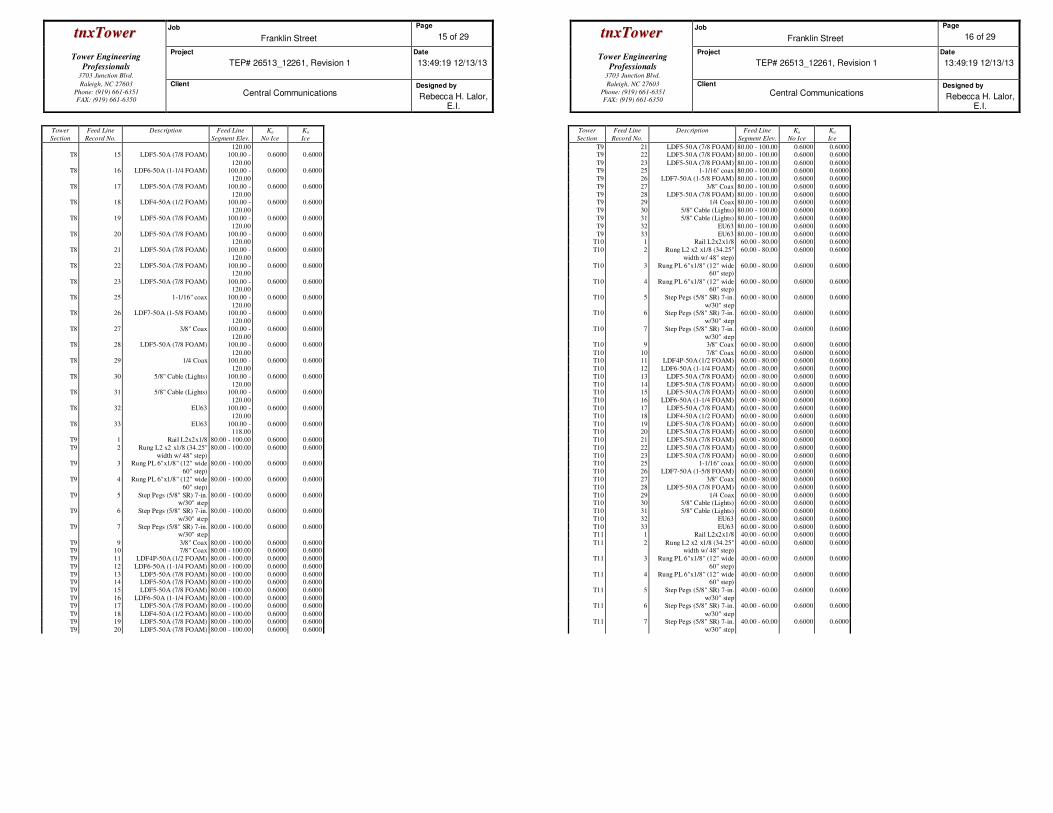
Shielding Factor Ka
Tower
Section
Feed Line
Record No.
Description Feed Line
Segment Elev.
Ka
No Ice
Ka
Ice
T1 3 Rung PL 6"x1/8" (12" wide
60" step)
240.00 -
255.00
0.6000 0.6000
T1 4 Rung PL 6"x1/8" (12" wide
60" step)
240.00 -
255.00
0.6000 0.6000
T1 5 Step Pegs (5/8" SR) 7-in.
w/30" step
240.00 -
255.00
0.6000 0.6000
T1 6 Step Pegs (5/8" SR) 7-in.
w/30" step
240.00 -
255.00
0.6000 0.6000
T1 7 Step Pegs (5/8" SR) 7-in.
w/30" step
240.00 -
255.00
0.6000 0.6000
T1 9 3/8" Coax 240.00 - 255.00
0.6000 0.6000
T1 10 7/8" Coax 240.00 -
255.00
0.6000 0.6000
T1 11 LDF4P-50A (1/2 FOAM) 240.00 - 255.00
0.6000 0.6000
T1 12 LDF6-50A (1-1/4 FOAM) 240.00 - 250.50
0.6000 0.6000
T1 13 LDF5-50A (7/8 FOAM) 240.00 -
248.00
0.6000 0.6000
T1 14 LDF5-50A (7/8 FOAM) 240.00 - 253.00
0.6000 0.6000
T1 15 LDF5-50A (7/8 FOAM) 240.00 -
249.00
0.6000 0.6000
T1 16 LDF6-50A (1-1/4 FOAM) 240.00 -
250.00
0.6000 0.6000
T1 17 LDF5-50A (7/8 FOAM) 240.00 -
250.00
0.6000 0.6000
T1 18 LDF4-50A (1/2 FOAM) 240.00 -
245.00
0.6000 0.6000
T1 19 LDF5-50A (7/8 FOAM) 240.00 -
240.50
0.6000 0.6000
T2 3 Rung PL 6"x1/8" (12" wide
60" step)
220.00 -
240.00
0.6000 0.6000
T2 4 Rung PL 6"x1/8" (12" wide 60" step)
220.00 - 240.00
0.6000 0.6000
T2 5 Step Pegs (5/8" SR) 7-in.
w/30" step
220.00 -
240.00
0.6000 0.6000
T2 6 Step Pegs (5/8" SR) 7-in. 220.00 - 0.6000 0.6000
ttnnxxTToowweerr Job
Franklin Street
Page
10 of 29
Tower Engineering
Professionals
3703 Junction Blvd.
Project
TEP# 26513_12261, Revision 1
Date
13:49:19 12/13/13
Raleigh, NC 27603
Phone: (919) 661-6351
FAX: (919) 661-6350
Client
Central Communications Designed by
Rebecca H. Lalor, E.I.
Tower
Section
Feed Line
Record No.
Description Feed Line
Segment Elev.
Ka
No Ice
Ka
Ice
w/30" step 240.00 T2 7 Step Pegs (5/8" SR) 7-in.
w/30" step
220.00 -
240.00
0.6000 0.6000
T2 9 3/8" Coax 220.00 -
240.00
0.6000 0.6000
T2 10 7/8" Coax 220.00 -
240.00
0.6000 0.6000
T2 11 LDF4P-50A (1/2 FOAM) 220.00 -
240.00
0.6000 0.6000
T2 12 LDF6-50A (1-1/4 FOAM) 220.00 -
240.00
0.6000 0.6000
T2 13 LDF5-50A (7/8 FOAM) 220.00 - 240.00
0.6000 0.6000
T2 14 LDF5-50A (7/8 FOAM) 220.00 -
240.00
0.6000 0.6000
T2 15 LDF5-50A (7/8 FOAM) 220.00 - 240.00
0.6000 0.6000
T2 16 LDF6-50A (1-1/4 FOAM) 220.00 - 240.00
0.6000 0.6000
T2 17 LDF5-50A (7/8 FOAM) 220.00 -
240.00
0.6000 0.6000
T2 18 LDF4-50A (1/2 FOAM) 220.00 -
240.00
0.6000 0.6000
T2 19 LDF5-50A (7/8 FOAM) 220.00 -
240.00
0.6000 0.6000
T2 20 LDF5-50A (7/8 FOAM) 220.00 -
231.50
0.6000 0.6000
T2 21 LDF5-50A (7/8 FOAM) 220.00 -
227.00
0.6000 0.6000
T3 3 Rung PL 6"x1/8" (12" wide
60" step)
200.00 -
220.00
0.6000 0.6000
T3 4 Rung PL 6"x1/8" (12" wide
60" step)
200.00 -
220.00
0.6000 0.6000
T3 5 Step Pegs (5/8" SR) 7-in.
w/30" step
200.00 -
220.00
0.6000 0.6000
T3 6 Step Pegs (5/8" SR) 7-in. w/30" step
200.00 - 220.00
0.6000 0.6000
T3 7 Step Pegs (5/8" SR) 7-in.
w/30" step
200.00 -
220.00
0.6000 0.6000
T3 9 3/8" Coax 200.00 - 220.00
0.6000 0.6000
T3 10 7/8" Coax 200.00 -
220.00
0.6000 0.6000
T3 11 LDF4P-50A (1/2 FOAM) 200.00 -
220.00
0.6000 0.6000
T3 12 LDF6-50A (1-1/4 FOAM) 200.00 -
220.00
0.6000 0.6000
T3 13 LDF5-50A (7/8 FOAM) 200.00 -
220.00
0.6000 0.6000
T3 14 LDF5-50A (7/8 FOAM) 200.00 -
220.00
0.6000 0.6000
T3 15 LDF5-50A (7/8 FOAM) 200.00 -
220.00
0.6000 0.6000
T3 16 LDF6-50A (1-1/4 FOAM) 200.00 -
220.00
0.6000 0.6000
T3 17 LDF5-50A (7/8 FOAM) 200.00 -
220.00
0.6000 0.6000
T3 18 LDF4-50A (1/2 FOAM) 200.00 - 220.00
0.6000 0.6000
T3 19 LDF5-50A (7/8 FOAM) 200.00 - 220.00
0.6000 0.6000
T3 20 LDF5-50A (7/8 FOAM) 200.00 - 0.6000 0.6000
ttnnxxTToowweerr Job
Franklin Street
Page
11 of 29
Tower Engineering
Professionals
3703 Junction Blvd.
Project
TEP# 26513_12261, Revision 1
Date
13:49:19 12/13/13
Raleigh, NC 27603
Phone: (919) 661-6351
FAX: (919) 661-6350
Client
Central Communications Designed by
Rebecca H. Lalor, E.I.
Tower
Section
Feed Line
Record No.
Description Feed Line
Segment Elev.
Ka
No Ice
Ka
Ice
220.00 T3 21 LDF5-50A (7/8 FOAM) 200.00 -
220.00
0.6000 0.6000
T3 22 LDF5-50A (7/8 FOAM) 200.00 -
214.92
0.6000 0.6000
T3 23 LDF5-50A (7/8 FOAM) 200.00 -
207.50
0.6000 0.6000
T4 1 Rail L2x2x1/8 180.00 -
182.00
0.6000 0.6000
T4 2 Rung L2 x2 x1/8 (34.25"
width w/ 48" step)
180.00 -
182.00
0.6000 0.6000
T4 3 Rung PL 6"x1/8" (12" wide 60" step)
180.00 - 200.00
0.6000 0.6000
T4 4 Rung PL 6"x1/8" (12" wide
60" step)
180.00 -
200.00
0.6000 0.6000
T4 5 Step Pegs (5/8" SR) 7-in. w/30" step
180.00 - 200.00
0.6000 0.6000
T4 6 Step Pegs (5/8" SR) 7-in. w/30" step
180.00 - 200.00
0.6000 0.6000
T4 7 Step Pegs (5/8" SR) 7-in.
w/30" step
180.00 -
200.00
0.6000 0.6000
T4 9 3/8" Coax 180.00 -
200.00
0.6000 0.6000
T4 10 7/8" Coax 180.00 -
200.00
0.6000 0.6000
T4 11 LDF4P-50A (1/2 FOAM) 180.00 -
200.00
0.6000 0.6000
T4 12 LDF6-50A (1-1/4 FOAM) 180.00 -
200.00
0.6000 0.6000
T4 13 LDF5-50A (7/8 FOAM) 180.00 -
200.00
0.6000 0.6000
T4 14 LDF5-50A (7/8 FOAM) 180.00 -
200.00
0.6000 0.6000
T4 15 LDF5-50A (7/8 FOAM) 180.00 -
200.00
0.6000 0.6000
T4 16 LDF6-50A (1-1/4 FOAM) 180.00 - 200.00
0.6000 0.6000
T4 17 LDF5-50A (7/8 FOAM) 180.00 -
200.00
0.6000 0.6000
T4 18 LDF4-50A (1/2 FOAM) 180.00 - 200.00
0.6000 0.6000
T4 19 LDF5-50A (7/8 FOAM) 180.00 -
200.00
0.6000 0.6000
T4 20 LDF5-50A (7/8 FOAM) 180.00 -
200.00
0.6000 0.6000
T4 21 LDF5-50A (7/8 FOAM) 180.00 -
200.00
0.6000 0.6000
T4 22 LDF5-50A (7/8 FOAM) 180.00 -
200.00
0.6000 0.6000
T4 23 LDF5-50A (7/8 FOAM) 180.00 -
200.00
0.6000 0.6000
T4 25 1-1/16" coax 180.00 -
182.00
0.6000 0.6000
T4 26 LDF7-50A (1-5/8 FOAM) 180.00 -
182.00
0.6000 0.6000
T4 27 3/8" Coax 180.00 -
182.00
0.6000 0.6000
T5 1 Rail L2x2x1/8 160.00 - 180.00
0.6000 0.6000
T5 2 Rung L2 x2 x1/8 (34.25" width w/ 48" step)
160.00 - 180.00
0.6000 0.6000
T5 3 Rung PL 6"x1/8" (12" wide 160.00 - 0.6000 0.6000
ttnnxxTToowweerr Job
Franklin Street
Page
12 of 29
Tower Engineering
Professionals
3703 Junction Blvd.
Project
TEP# 26513_12261, Revision 1
Date
13:49:19 12/13/13
Raleigh, NC 27603
Phone: (919) 661-6351
FAX: (919) 661-6350
Client
Central Communications Designed by
Rebecca H. Lalor, E.I.
Tower
Section
Feed Line
Record No.
Description Feed Line
Segment Elev.
Ka
No Ice
Ka
Ice
60" step) 180.00 T5 4 Rung PL 6"x1/8" (12" wide
60" step)
160.00 -
180.00
0.6000 0.6000
T5 5 Step Pegs (5/8" SR) 7-in.
w/30" step
160.00 -
180.00
0.6000 0.6000
T5 6 Step Pegs (5/8" SR) 7-in.
w/30" step
160.00 -
180.00
0.6000 0.6000
T5 7 Step Pegs (5/8" SR) 7-in.
w/30" step
160.00 -
180.00
0.6000 0.6000
T5 9 3/8" Coax 160.00 -
180.00
0.6000 0.6000
T5 10 7/8" Coax 160.00 - 180.00
0.6000 0.6000
T5 11 LDF4P-50A (1/2 FOAM) 160.00 -
180.00
0.6000 0.6000
T5 12 LDF6-50A (1-1/4 FOAM) 160.00 - 180.00
0.6000 0.6000
T5 13 LDF5-50A (7/8 FOAM) 160.00 - 180.00
0.6000 0.6000
T5 14 LDF5-50A (7/8 FOAM) 160.00 -
180.00
0.6000 0.6000
T5 15 LDF5-50A (7/8 FOAM) 160.00 -
180.00
0.6000 0.6000
T5 16 LDF6-50A (1-1/4 FOAM) 160.00 -
180.00
0.6000 0.6000
T5 17 LDF5-50A (7/8 FOAM) 160.00 -
180.00
0.6000 0.6000
T5 18 LDF4-50A (1/2 FOAM) 160.00 -
180.00
0.6000 0.6000
T5 19 LDF5-50A (7/8 FOAM) 160.00 -
180.00
0.6000 0.6000
T5 20 LDF5-50A (7/8 FOAM) 160.00 -
180.00
0.6000 0.6000
T5 21 LDF5-50A (7/8 FOAM) 160.00 -
180.00
0.6000 0.6000
T5 22 LDF5-50A (7/8 FOAM) 160.00 - 180.00
0.6000 0.6000
T5 23 LDF5-50A (7/8 FOAM) 160.00 -
180.00
0.6000 0.6000
T5 25 1-1/16" coax 160.00 - 180.00
0.6000 0.6000
T5 26 LDF7-50A (1-5/8 FOAM) 160.00 -
180.00
0.6000 0.6000
T5 27 3/8" Coax 160.00 -
180.00
0.6000 0.6000
T5 28 LDF5-50A (7/8 FOAM) 160.00 -
172.00
0.6000 0.6000
T6 1 Rail L2x2x1/8 140.00 -
160.00
0.6000 0.6000
T6 2 Rung L2 x2 x1/8 (34.25"
width w/ 48" step)
140.00 -
160.00
0.6000 0.6000
T6 3 Rung PL 6"x1/8" (12" wide
60" step)
140.00 -
160.00
0.6000 0.6000
T6 4 Rung PL 6"x1/8" (12" wide
60" step)
140.00 -
160.00
0.6000 0.6000
T6 5 Step Pegs (5/8" SR) 7-in.
w/30" step
140.00 -
160.00
0.6000 0.6000
T6 6 Step Pegs (5/8" SR) 7-in. w/30" step
140.00 - 160.00
0.6000 0.6000
T6 7 Step Pegs (5/8" SR) 7-in. w/30" step
140.00 - 160.00
0.6000 0.6000
T6 9 3/8" Coax 140.00 - 0.6000 0.6000
ttnnxxTToowweerr Job
Franklin Street
Page
13 of 29
Tower Engineering
Professionals
3703 Junction Blvd.
Project
TEP# 26513_12261, Revision 1
Date
13:49:19 12/13/13
Raleigh, NC 27603
Phone: (919) 661-6351
FAX: (919) 661-6350
Client
Central Communications Designed by
Rebecca H. Lalor, E.I.
Tower
Section
Feed Line
Record No.
Description Feed Line
Segment Elev.
Ka
No Ice
Ka
Ice
160.00 T6 10 7/8" Coax 140.00 -
160.00
0.6000 0.6000
T6 11 LDF4P-50A (1/2 FOAM) 140.00 -
160.00
0.6000 0.6000
T6 12 LDF6-50A (1-1/4 FOAM) 140.00 -
160.00
0.6000 0.6000
T6 13 LDF5-50A (7/8 FOAM) 140.00 -
160.00
0.6000 0.6000
T6 14 LDF5-50A (7/8 FOAM) 140.00 -
160.00
0.6000 0.6000
T6 15 LDF5-50A (7/8 FOAM) 140.00 - 160.00
0.6000 0.6000
T6 16 LDF6-50A (1-1/4 FOAM) 140.00 -
160.00
0.6000 0.6000
T6 17 LDF5-50A (7/8 FOAM) 140.00 - 160.00
0.6000 0.6000
T6 18 LDF4-50A (1/2 FOAM) 140.00 - 160.00
0.6000 0.6000
T6 19 LDF5-50A (7/8 FOAM) 140.00 -
160.00
0.6000 0.6000
T6 20 LDF5-50A (7/8 FOAM) 140.00 -
160.00
0.6000 0.6000
T6 21 LDF5-50A (7/8 FOAM) 140.00 -
160.00
0.6000 0.6000
T6 22 LDF5-50A (7/8 FOAM) 140.00 -
160.00
0.6000 0.6000
T6 23 LDF5-50A (7/8 FOAM) 140.00 -
160.00
0.6000 0.6000
T6 25 1-1/16" coax 140.00 -
160.00
0.6000 0.6000
T6 26 LDF7-50A (1-5/8 FOAM) 140.00 -
160.00
0.6000 0.6000
T6 27 3/8" Coax 140.00 -
160.00
0.6000 0.6000
T6 28 LDF5-50A (7/8 FOAM) 140.00 - 160.00
0.6000 0.6000
T6 29 1/4 Coax 140.00 -
153.33
0.6000 0.6000
T7 1 Rail L2x2x1/8 120.00 - 140.00
0.6000 0.6000
T7 2 Rung L2 x2 x1/8 (34.25"
width w/ 48" step)
120.00 -
140.00
0.6000 0.6000
T7 3 Rung PL 6"x1/8" (12" wide
60" step)
120.00 -
140.00
0.6000 0.6000
T7 4 Rung PL 6"x1/8" (12" wide
60" step)
120.00 -
140.00
0.6000 0.6000
T7 5 Step Pegs (5/8" SR) 7-in.
w/30" step
120.00 -
140.00
0.6000 0.6000
T7 6 Step Pegs (5/8" SR) 7-in.
w/30" step
120.00 -
140.00
0.6000 0.6000
T7 7 Step Pegs (5/8" SR) 7-in.
w/30" step
120.00 -
140.00
0.6000 0.6000
T7 9 3/8" Coax 120.00 -
140.00
0.6000 0.6000
T7 10 7/8" Coax 120.00 -
140.00
0.6000 0.6000
T7 11 LDF4P-50A (1/2 FOAM) 120.00 - 140.00
0.6000 0.6000
T7 12 LDF6-50A (1-1/4 FOAM) 120.00 - 140.00
0.6000 0.6000
T7 13 LDF5-50A (7/8 FOAM) 120.00 - 0.6000 0.6000
ttnnxxTToowweerr Job
Franklin Street
Page
14 of 29
Tower Engineering
Professionals
3703 Junction Blvd.
Project
TEP# 26513_12261, Revision 1
Date
13:49:19 12/13/13
Raleigh, NC 27603
Phone: (919) 661-6351
FAX: (919) 661-6350
Client
Central Communications Designed by
Rebecca H. Lalor, E.I.
Tower
Section
Feed Line
Record No.
Description Feed Line
Segment Elev.
Ka
No Ice
Ka
Ice
140.00 T7 14 LDF5-50A (7/8 FOAM) 120.00 -
140.00
0.6000 0.6000
T7 15 LDF5-50A (7/8 FOAM) 120.00 -
140.00
0.6000 0.6000
T7 16 LDF6-50A (1-1/4 FOAM) 120.00 -
140.00
0.6000 0.6000
T7 17 LDF5-50A (7/8 FOAM) 120.00 -
140.00
0.6000 0.6000
T7 18 LDF4-50A (1/2 FOAM) 120.00 -
140.00
0.6000 0.6000
T7 19 LDF5-50A (7/8 FOAM) 120.00 - 140.00
0.6000 0.6000
T7 20 LDF5-50A (7/8 FOAM) 120.00 -
140.00
0.6000 0.6000
T7 21 LDF5-50A (7/8 FOAM) 120.00 - 140.00
0.6000 0.6000
T7 22 LDF5-50A (7/8 FOAM) 120.00 - 140.00
0.6000 0.6000
T7 23 LDF5-50A (7/8 FOAM) 120.00 -
140.00
0.6000 0.6000
T7 25 1-1/16" coax 120.00 -
140.00
0.6000 0.6000
T7 26 LDF7-50A (1-5/8 FOAM) 120.00 -
140.00
0.6000 0.6000
T7 27 3/8" Coax 120.00 -
140.00
0.6000 0.6000
T7 28 LDF5-50A (7/8 FOAM) 120.00 -
140.00
0.6000 0.6000
T7 29 1/4 Coax 120.00 -
140.00
0.6000 0.6000
T7 30 5/8" Cable (Lights) 120.00 -
131.00
0.6000 0.6000
T7 31 5/8" Cable (Lights) 120.00 -
131.00
0.6000 0.6000
T7 32 EU63 120.00 - 124.00
0.6000 0.6000
T8 1 Rail L2x2x1/8 100.00 -
120.00
0.6000 0.6000
T8 2 Rung L2 x2 x1/8 (34.25" width w/ 48" step)
100.00 - 120.00
0.6000 0.6000
T8 3 Rung PL 6"x1/8" (12" wide
60" step)
100.00 -
120.00
0.6000 0.6000
T8 4 Rung PL 6"x1/8" (12" wide
60" step)
100.00 -
120.00
0.6000 0.6000
T8 5 Step Pegs (5/8" SR) 7-in.
w/30" step
100.00 -
120.00
0.6000 0.6000
T8 6 Step Pegs (5/8" SR) 7-in.
w/30" step
100.00 -
120.00
0.6000 0.6000
T8 7 Step Pegs (5/8" SR) 7-in.
w/30" step
100.00 -
120.00
0.6000 0.6000
T8 9 3/8" Coax 100.00 -
120.00
0.6000 0.6000
T8 10 7/8" Coax 100.00 -
120.00
0.6000 0.6000
T8 11 LDF4P-50A (1/2 FOAM) 100.00 -
120.00
0.6000 0.6000
T8 12 LDF6-50A (1-1/4 FOAM) 100.00 - 120.00
0.6000 0.6000
T8 13 LDF5-50A (7/8 FOAM) 100.00 - 120.00
0.6000 0.6000
T8 14 LDF5-50A (7/8 FOAM) 100.00 - 0.6000 0.6000
ttnnxxTToowweerr Job
Franklin Street
Page
15 of 29
Tower Engineering
Professionals
3703 Junction Blvd.
Project
TEP# 26513_12261, Revision 1
Date
13:49:19 12/13/13
Raleigh, NC 27603
Phone: (919) 661-6351
FAX: (919) 661-6350
Client
Central Communications Designed by
Rebecca H. Lalor, E.I.
Tower
Section
Feed Line
Record No.
Description Feed Line
Segment Elev.
Ka
No Ice
Ka
Ice
120.00 T8 15 LDF5-50A (7/8 FOAM) 100.00 -
120.00
0.6000 0.6000
T8 16 LDF6-50A (1-1/4 FOAM) 100.00 -
120.00
0.6000 0.6000
T8 17 LDF5-50A (7/8 FOAM) 100.00 -
120.00
0.6000 0.6000
T8 18 LDF4-50A (1/2 FOAM) 100.00 -
120.00
0.6000 0.6000
T8 19 LDF5-50A (7/8 FOAM) 100.00 -
120.00
0.6000 0.6000
T8 20 LDF5-50A (7/8 FOAM) 100.00 - 120.00
0.6000 0.6000
T8 21 LDF5-50A (7/8 FOAM) 100.00 -
120.00
0.6000 0.6000
T8 22 LDF5-50A (7/8 FOAM) 100.00 - 120.00
0.6000 0.6000
T8 23 LDF5-50A (7/8 FOAM) 100.00 - 120.00
0.6000 0.6000
T8 25 1-1/16" coax 100.00 -
120.00
0.6000 0.6000
T8 26 LDF7-50A (1-5/8 FOAM) 100.00 -
120.00
0.6000 0.6000
T8 27 3/8" Coax 100.00 -
120.00
0.6000 0.6000
T8 28 LDF5-50A (7/8 FOAM) 100.00 -
120.00
0.6000 0.6000
T8 29 1/4 Coax 100.00 -
120.00
0.6000 0.6000
T8 30 5/8" Cable (Lights) 100.00 -
120.00
0.6000 0.6000
T8 31 5/8" Cable (Lights) 100.00 -
120.00
0.6000 0.6000
T8 32 EU63 100.00 -
120.00
0.6000 0.6000
T8 33 EU63 100.00 - 118.00
0.6000 0.6000
T9 1 Rail L2x2x1/8 80.00 - 100.00 0.6000 0.6000
T9 2 Rung L2 x2 x1/8 (34.25"
width w/ 48" step)
80.00 - 100.00 0.6000 0.6000
T9 3 Rung PL 6"x1/8" (12" wide
60" step)
80.00 - 100.00 0.6000 0.6000
T9 4 Rung PL 6"x1/8" (12" wide
60" step)
80.00 - 100.00 0.6000 0.6000
T9 5 Step Pegs (5/8" SR) 7-in. w/30" step
80.00 - 100.00 0.6000 0.6000
T9 6 Step Pegs (5/8" SR) 7-in.
w/30" step
80.00 - 100.00 0.6000 0.6000
T9 7 Step Pegs (5/8" SR) 7-in. w/30" step
80.00 - 100.00 0.6000 0.6000
T9 9 3/8" Coax 80.00 - 100.00 0.6000 0.6000 T9 10 7/8" Coax 80.00 - 100.00 0.6000 0.6000
T9 11 LDF4P-50A (1/2 FOAM) 80.00 - 100.00 0.6000 0.6000
T9 12 LDF6-50A (1-1/4 FOAM) 80.00 - 100.00 0.6000 0.6000
T9 13 LDF5-50A (7/8 FOAM) 80.00 - 100.00 0.6000 0.6000 T9 14 LDF5-50A (7/8 FOAM) 80.00 - 100.00 0.6000 0.6000
T9 15 LDF5-50A (7/8 FOAM) 80.00 - 100.00 0.6000 0.6000
T9 16 LDF6-50A (1-1/4 FOAM) 80.00 - 100.00 0.6000 0.6000 T9 17 LDF5-50A (7/8 FOAM) 80.00 - 100.00 0.6000 0.6000
T9 18 LDF4-50A (1/2 FOAM) 80.00 - 100.00 0.6000 0.6000 T9 19 LDF5-50A (7/8 FOAM) 80.00 - 100.00 0.6000 0.6000
T9 20 LDF5-50A (7/8 FOAM) 80.00 - 100.00 0.6000 0.6000
ttnnxxTToowweerr Job
Franklin Street
Page
16 of 29
Tower Engineering
Professionals
3703 Junction Blvd.
Project
TEP# 26513_12261, Revision 1
Date
13:49:19 12/13/13
Raleigh, NC 27603
Phone: (919) 661-6351
FAX: (919) 661-6350
Client
Central Communications Designed by
Rebecca H. Lalor, E.I.
Tower
Section
Feed Line
Record No.
Description Feed Line
Segment Elev.
Ka
No Ice
Ka
Ice
T9 21 LDF5-50A (7/8 FOAM) 80.00 - 100.00 0.6000 0.6000 T9 22 LDF5-50A (7/8 FOAM) 80.00 - 100.00 0.6000 0.6000
T9 23 LDF5-50A (7/8 FOAM) 80.00 - 100.00 0.6000 0.6000 T9 25 1-1/16" coax 80.00 - 100.00 0.6000 0.6000
T9 26 LDF7-50A (1-5/8 FOAM) 80.00 - 100.00 0.6000 0.6000
T9 27 3/8" Coax 80.00 - 100.00 0.6000 0.6000
T9 28 LDF5-50A (7/8 FOAM) 80.00 - 100.00 0.6000 0.6000 T9 29 1/4 Coax 80.00 - 100.00 0.6000 0.6000
T9 30 5/8" Cable (Lights) 80.00 - 100.00 0.6000 0.6000
T9 31 5/8" Cable (Lights) 80.00 - 100.00 0.6000 0.6000
T9 32 EU63 80.00 - 100.00 0.6000 0.6000
T9 33 EU63 80.00 - 100.00 0.6000 0.6000 T10 1 Rail L2x2x1/8 60.00 - 80.00 0.6000 0.6000
T10 2 Rung L2 x2 x1/8 (34.25"
width w/ 48" step)
60.00 - 80.00 0.6000 0.6000
T10 3 Rung PL 6"x1/8" (12" wide 60" step)
60.00 - 80.00 0.6000 0.6000
T10 4 Rung PL 6"x1/8" (12" wide 60" step)
60.00 - 80.00 0.6000 0.6000
T10 5 Step Pegs (5/8" SR) 7-in.
w/30" step
60.00 - 80.00 0.6000 0.6000
T10 6 Step Pegs (5/8" SR) 7-in.
w/30" step
60.00 - 80.00 0.6000 0.6000
T10 7 Step Pegs (5/8" SR) 7-in.
w/30" step
60.00 - 80.00 0.6000 0.6000
T10 9 3/8" Coax 60.00 - 80.00 0.6000 0.6000
T10 10 7/8" Coax 60.00 - 80.00 0.6000 0.6000 T10 11 LDF4P-50A (1/2 FOAM) 60.00 - 80.00 0.6000 0.6000
T10 12 LDF6-50A (1-1/4 FOAM) 60.00 - 80.00 0.6000 0.6000
T10 13 LDF5-50A (7/8 FOAM) 60.00 - 80.00 0.6000 0.6000
T10 14 LDF5-50A (7/8 FOAM) 60.00 - 80.00 0.6000 0.6000 T10 15 LDF5-50A (7/8 FOAM) 60.00 - 80.00 0.6000 0.6000
T10 16 LDF6-50A (1-1/4 FOAM) 60.00 - 80.00 0.6000 0.6000
T10 17 LDF5-50A (7/8 FOAM) 60.00 - 80.00 0.6000 0.6000
T10 18 LDF4-50A (1/2 FOAM) 60.00 - 80.00 0.6000 0.6000
T10 19 LDF5-50A (7/8 FOAM) 60.00 - 80.00 0.6000 0.6000 T10 20 LDF5-50A (7/8 FOAM) 60.00 - 80.00 0.6000 0.6000
T10 21 LDF5-50A (7/8 FOAM) 60.00 - 80.00 0.6000 0.6000
T10 22 LDF5-50A (7/8 FOAM) 60.00 - 80.00 0.6000 0.6000
T10 23 LDF5-50A (7/8 FOAM) 60.00 - 80.00 0.6000 0.6000 T10 25 1-1/16" coax 60.00 - 80.00 0.6000 0.6000
T10 26 LDF7-50A (1-5/8 FOAM) 60.00 - 80.00 0.6000 0.6000
T10 27 3/8" Coax 60.00 - 80.00 0.6000 0.6000
T10 28 LDF5-50A (7/8 FOAM) 60.00 - 80.00 0.6000 0.6000
T10 29 1/4 Coax 60.00 - 80.00 0.6000 0.6000 T10 30 5/8" Cable (Lights) 60.00 - 80.00 0.6000 0.6000
T10 31 5/8" Cable (Lights) 60.00 - 80.00 0.6000 0.6000
T10 32 EU63 60.00 - 80.00 0.6000 0.6000
T10 33 EU63 60.00 - 80.00 0.6000 0.6000 T11 1 Rail L2x2x1/8 40.00 - 60.00 0.6000 0.6000
T11 2 Rung L2 x2 x1/8 (34.25" width w/ 48" step)
40.00 - 60.00 0.6000 0.6000
T11 3 Rung PL 6"x1/8" (12" wide
60" step)
40.00 - 60.00 0.6000 0.6000
T11 4 Rung PL 6"x1/8" (12" wide 60" step)
40.00 - 60.00 0.6000 0.6000
T11 5 Step Pegs (5/8" SR) 7-in.
w/30" step
40.00 - 60.00 0.6000 0.6000
T11 6 Step Pegs (5/8" SR) 7-in.
w/30" step
40.00 - 60.00 0.6000 0.6000
T11 7 Step Pegs (5/8" SR) 7-in.
w/30" step
40.00 - 60.00 0.6000 0.6000
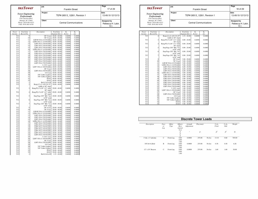
ttnnxxTToowweerr Job
Franklin Street
Page
17 of 29
Tower Engineering
Professionals
3703 Junction Blvd.
Project
TEP# 26513_12261, Revision 1
Date
13:49:19 12/13/13
Raleigh, NC 27603
Phone: (919) 661-6351
FAX: (919) 661-6350
Client
Central Communications Designed by
Rebecca H. Lalor, E.I.
Tower
Section
Feed Line
Record No.
Description Feed Line
Segment Elev.
Ka
No Ice
Ka
Ice
T11 9 3/8" Coax 40.00 - 60.00 0.6000 0.6000 T11 10 7/8" Coax 40.00 - 60.00 0.6000 0.6000
T11 11 LDF4P-50A (1/2 FOAM) 40.00 - 60.00 0.6000 0.6000 T11 12 LDF6-50A (1-1/4 FOAM) 40.00 - 60.00 0.6000 0.6000
T11 13 LDF5-50A (7/8 FOAM) 40.00 - 60.00 0.6000 0.6000
T11 14 LDF5-50A (7/8 FOAM) 40.00 - 60.00 0.6000 0.6000
T11 15 LDF5-50A (7/8 FOAM) 40.00 - 60.00 0.6000 0.6000 T11 16 LDF6-50A (1-1/4 FOAM) 40.00 - 60.00 0.6000 0.6000
T11 17 LDF5-50A (7/8 FOAM) 40.00 - 60.00 0.6000 0.6000
T11 18 LDF4-50A (1/2 FOAM) 40.00 - 60.00 0.6000 0.6000
T11 19 LDF5-50A (7/8 FOAM) 40.00 - 60.00 0.6000 0.6000
T11 20 LDF5-50A (7/8 FOAM) 40.00 - 60.00 0.6000 0.6000 T11 21 LDF5-50A (7/8 FOAM) 40.00 - 60.00 0.6000 0.6000
T11 22 LDF5-50A (7/8 FOAM) 40.00 - 60.00 0.6000 0.6000
T11 23 LDF5-50A (7/8 FOAM) 40.00 - 60.00 0.6000 0.6000
T11 25 1-1/16" coax 40.00 - 60.00 0.6000 0.6000 T11 26 LDF7-50A (1-5/8 FOAM) 40.00 - 60.00 0.6000 0.6000
T11 27 3/8" Coax 40.00 - 60.00 0.6000 0.6000 T11 28 LDF5-50A (7/8 FOAM) 40.00 - 60.00 0.6000 0.6000
T11 29 1/4 Coax 40.00 - 60.00 0.6000 0.6000
T11 30 5/8" Cable (Lights) 40.00 - 60.00 0.6000 0.6000 T11 31 5/8" Cable (Lights) 40.00 - 60.00 0.6000 0.6000
T11 32 EU63 40.00 - 60.00 0.6000 0.6000
T11 33 EU63 40.00 - 60.00 0.6000 0.6000
T12 1 Rail L2x2x1/8 20.00 - 40.00 0.6000 0.6000 T12 2 Rung L2 x2 x1/8 (34.25"
width w/ 48" step)
20.00 - 40.00 0.6000 0.6000
T12 3 Rung PL 6"x1/8" (12" wide
60" step)
20.00 - 40.00 0.6000 0.6000
T12 4 Rung PL 6"x1/8" (12" wide
60" step)
20.00 - 40.00 0.6000 0.6000
T12 5 Step Pegs (5/8" SR) 7-in.
w/30" step
20.00 - 40.00 0.6000 0.6000
T12 6 Step Pegs (5/8" SR) 7-in.
w/30" step
20.00 - 40.00 0.6000 0.6000
T12 7 Step Pegs (5/8" SR) 7-in. w/30" step
20.00 - 40.00 0.6000 0.6000
T12 9 3/8" Coax 20.00 - 40.00 0.6000 0.6000
T12 10 7/8" Coax 20.00 - 40.00 0.6000 0.6000
T12 11 LDF4P-50A (1/2 FOAM) 20.00 - 40.00 0.6000 0.6000 T12 12 LDF6-50A (1-1/4 FOAM) 20.00 - 40.00 0.6000 0.6000
T12 13 LDF5-50A (7/8 FOAM) 20.00 - 40.00 0.6000 0.6000
T12 14 LDF5-50A (7/8 FOAM) 20.00 - 40.00 0.6000 0.6000
T12 15 LDF5-50A (7/8 FOAM) 20.00 - 40.00 0.6000 0.6000
T12 16 LDF6-50A (1-1/4 FOAM) 20.00 - 40.00 0.6000 0.6000 T12 17 LDF5-50A (7/8 FOAM) 20.00 - 40.00 0.6000 0.6000
T12 18 LDF4-50A (1/2 FOAM) 20.00 - 40.00 0.6000 0.6000
T12 19 LDF5-50A (7/8 FOAM) 20.00 - 40.00 0.6000 0.6000
T12 20 LDF5-50A (7/8 FOAM) 20.00 - 40.00 0.6000 0.6000 T12 21 LDF5-50A (7/8 FOAM) 20.00 - 40.00 0.6000 0.6000
T12 22 LDF5-50A (7/8 FOAM) 20.00 - 40.00 0.6000 0.6000 T12 23 LDF5-50A (7/8 FOAM) 20.00 - 40.00 0.6000 0.6000
T12 25 1-1/16" coax 20.00 - 40.00 0.6000 0.6000
T12 26 LDF7-50A (1-5/8 FOAM) 20.00 - 40.00 0.6000 0.6000
T12 27 3/8" Coax 20.00 - 40.00 0.6000 0.6000 T12 28 LDF5-50A (7/8 FOAM) 20.00 - 40.00 0.6000 0.6000
T12 29 1/4 Coax 20.00 - 40.00 0.6000 0.6000
T12 30 5/8" Cable (Lights) 20.00 - 40.00 0.6000 0.6000 T12 31 5/8" Cable (Lights) 20.00 - 40.00 0.6000 0.6000
T12 32 EU63 20.00 - 40.00 0.6000 0.6000 T12 33 EU63 20.00 - 40.00 0.6000 0.6000
T13 1 Rail L2x2x1/8 1.33 - 20.00 0.6000 0.6000
ttnnxxTToowweerr Job
Franklin Street
Page
18 of 29
Tower Engineering
Professionals
3703 Junction Blvd.
Project
TEP# 26513_12261, Revision 1
Date
13:49:19 12/13/13
Raleigh, NC 27603
Phone: (919) 661-6351
FAX: (919) 661-6350
Client
Central Communications Designed by
Rebecca H. Lalor, E.I.
Tower
Section
Feed Line
Record No.
Description Feed Line
Segment Elev.
Ka
No Ice
Ka
Ice
T13 2 Rung L2 x2 x1/8 (34.25" width w/ 48" step)
1.33 - 20.00 0.6000 0.6000
T13 3 Rung PL 6"x1/8" (12" wide 60" step)
0.00 - 20.00 0.6000 0.6000
T13 4 Rung PL 6"x1/8" (12" wide
60" step)
0.00 - 20.00 0.6000 0.6000
T13 5 Step Pegs (5/8" SR) 7-in. w/30" step
0.00 - 20.00 0.6000 0.6000
T13 6 Step Pegs (5/8" SR) 7-in.
w/30" step
0.00 - 20.00 0.6000 0.6000
T13 7 Step Pegs (5/8" SR) 7-in.
w/30" step
0.00 - 20.00 0.6000 0.6000
T13 9 3/8" Coax 5.00 - 20.00 0.6000 0.6000
T13 10 7/8" Coax 5.00 - 20.00 0.6000 0.6000
T13 11 LDF4P-50A (1/2 FOAM) 5.00 - 20.00 0.6000 0.6000
T13 12 LDF6-50A (1-1/4 FOAM) 5.00 - 20.00 0.6000 0.6000 T13 13 LDF5-50A (7/8 FOAM) 6.00 - 20.00 0.6000 0.6000
T13 14 LDF5-50A (7/8 FOAM) 6.00 - 20.00 0.6000 0.6000 T13 15 LDF5-50A (7/8 FOAM) 6.00 - 20.00 0.6000 0.6000
T13 16 LDF6-50A (1-1/4 FOAM) 5.00 - 20.00 0.6000 0.6000
T13 17 LDF5-50A (7/8 FOAM) 5.00 - 20.00 0.6000 0.6000 T13 18 LDF4-50A (1/2 FOAM) 5.00 - 20.00 0.6000 0.6000
T13 19 LDF5-50A (7/8 FOAM) 5.00 - 20.00 0.6000 0.6000
T13 20 LDF5-50A (7/8 FOAM) 5.00 - 20.00 0.6000 0.6000
T13 21 LDF5-50A (7/8 FOAM) 6.00 - 20.00 0.6000 0.6000 T13 22 LDF5-50A (7/8 FOAM) 5.00 - 20.00 0.6000 0.6000
T13 23 LDF5-50A (7/8 FOAM) 6.00 - 20.00 0.6000 0.6000 T13 25 1-1/16" coax 1.00 - 20.00 0.6000 0.6000
T13 26 LDF7-50A (1-5/8 FOAM) 3.00 - 20.00 0.6000 0.6000
T13 27 3/8" Coax 3.00 - 20.00 0.6000 0.6000
T13 28 LDF5-50A (7/8 FOAM) 5.00 - 20.00 0.6000 0.6000 T13 29 1/4 Coax 5.00 - 20.00 0.6000 0.6000
T13 30 5/8" Cable (Lights) 9.00 - 20.00 0.6000 0.6000
T13 31 5/8" Cable (Lights) 9.00 - 20.00 0.6000 0.6000
T13 32 EU63 5.00 - 20.00 0.6000 0.6000
T13 33 EU63 5.00 - 20.00 0.6000 0.6000
Discrete Tower Loads
Description Face
or
Leg
Offset
Type
Offsets:
Horz
Lateral
Vert
ft
ft
ft
Azimuth
Adjustment
°
Placement
ft
CAAA
Front
ft2
CAAA
Side
ft2
Weight
lb
4' dia. x 3' antenna C From Leg 0.00
0.00
3.00
0.0000 255.00 No Ice 13.10 9.60 785.00
5/8''x6-ft LRod B From Leg 0.00
0.00 3.00
0.0000 255.00 No Ice 0.38 0.38 6.26
12'' x 24'' Beacon C From Leg 0.00
0.00
1.00
0.0000 255.00 No Ice 1.60 1.60 30.00
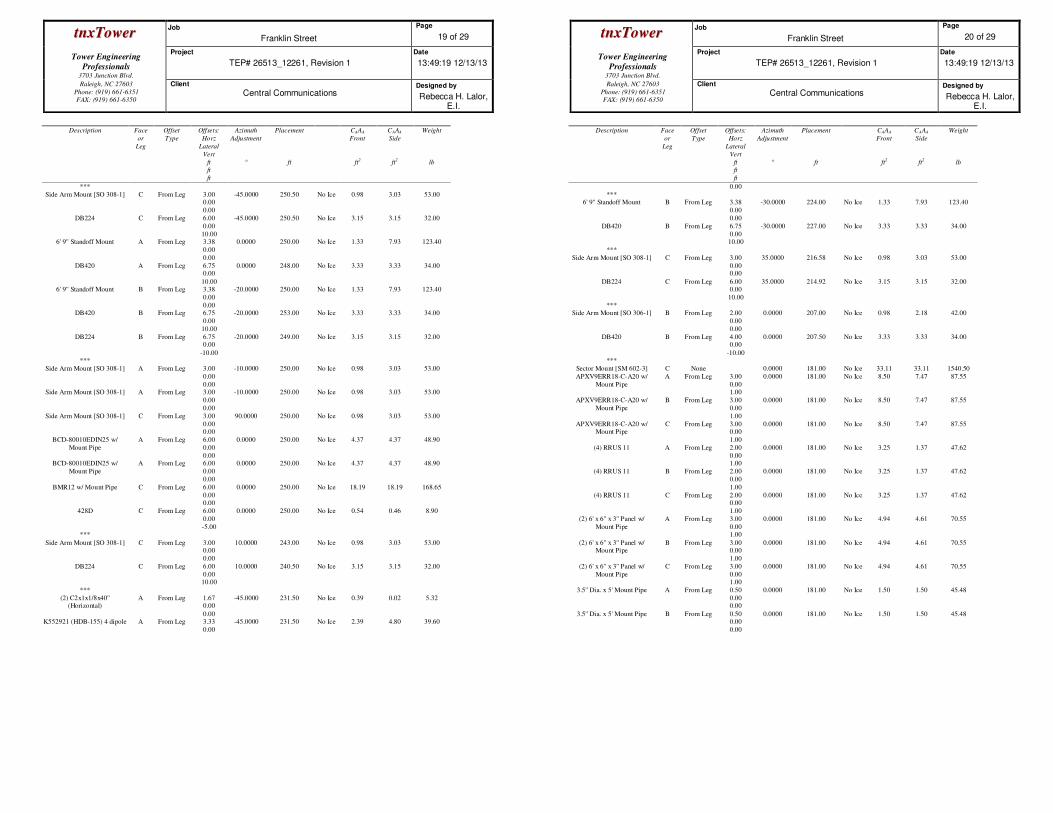
ttnnxxTToowweerr Job
Franklin Street
Page
19 of 29
Tower Engineering
Professionals
3703 Junction Blvd.
Project
TEP# 26513_12261, Revision 1
Date
13:49:19 12/13/13
Raleigh, NC 27603
Phone: (919) 661-6351
FAX: (919) 661-6350
Client
Central Communications Designed by
Rebecca H. Lalor, E.I.
Description Face
or
Leg
Offset
Type
Offsets:
Horz
Lateral
Vert
ft
ft
ft
Azimuth
Adjustment
°
Placement
ft
CAAA
Front
ft2
CAAA
Side
ft2
Weight
lb
***
Side Arm Mount [SO 308-1] C From Leg 3.00 0.00
0.00
-45.0000 250.50 No Ice 0.98 3.03 53.00
DB224 C From Leg 6.00
0.00
10.00
-45.0000 250.50 No Ice 3.15 3.15 32.00
6' 9'' Standoff Mount A From Leg 3.38
0.00
0.00
0.0000 250.00 No Ice 1.33 7.93 123.40
DB420 A From Leg 6.75 0.00
10.00
0.0000 248.00 No Ice 3.33 3.33 34.00
6' 9'' Standoff Mount B From Leg 3.38
0.00
0.00
-20.0000 250.00 No Ice 1.33 7.93 123.40
DB420 B From Leg 6.75
0.00
10.00
-20.0000 253.00 No Ice 3.33 3.33 34.00
DB224 B From Leg 6.75 0.00
-10.00
-20.0000 249.00 No Ice 3.15 3.15 32.00
***
Side Arm Mount [SO 308-1] A From Leg 3.00
0.00
0.00
-10.0000 250.00 No Ice 0.98 3.03 53.00
Side Arm Mount [SO 308-1] A From Leg 3.00
0.00
0.00
-10.0000 250.00 No Ice 0.98 3.03 53.00
Side Arm Mount [SO 308-1] C From Leg 3.00
0.00 0.00
90.0000 250.00 No Ice 0.98 3.03 53.00
BCD-80010EDIN25 w/
Mount Pipe
A From Leg 6.00
0.00
0.00
0.0000 250.00 No Ice 4.37 4.37 48.90
BCD-80010EDIN25 w/
Mount Pipe
A From Leg 6.00
0.00
0.00
0.0000 250.00 No Ice 4.37 4.37 48.90
BMR12 w/ Mount Pipe C From Leg 6.00
0.00 0.00
0.0000 250.00 No Ice 18.19 18.19 168.65
428D C From Leg 6.00
0.00
-5.00
0.0000 250.00 No Ice 0.54 0.46 8.90
***
Side Arm Mount [SO 308-1] C From Leg 3.00 0.00
0.00
10.0000 243.00 No Ice 0.98 3.03 53.00
DB224 C From Leg 6.00
0.00 10.00
10.0000 240.50 No Ice 3.15 3.15 32.00
***
(2) C2x1x1/8x40'' (Horizontal)
A From Leg 1.67 0.00
0.00
-45.0000 231.50 No Ice 0.39 0.02 5.32
K552921 (HDB-155) 4 dipole A From Leg 3.33
0.00
-45.0000 231.50 No Ice 2.39 4.80 39.60
ttnnxxTToowweerr Job
Franklin Street
Page
20 of 29
Tower Engineering
Professionals
3703 Junction Blvd.
Project
TEP# 26513_12261, Revision 1
Date
13:49:19 12/13/13
Raleigh, NC 27603
Phone: (919) 661-6351
FAX: (919) 661-6350
Client
Central Communications Designed by
Rebecca H. Lalor, E.I.
Description Face
or
Leg
Offset
Type
Offsets:
Horz
Lateral
Vert
ft
ft
ft
Azimuth
Adjustment
°
Placement
ft
CAAA
Front
ft2
CAAA
Side
ft2
Weight
lb
0.00
*** 6' 9'' Standoff Mount B From Leg 3.38
0.00
0.00
-30.0000 224.00 No Ice 1.33 7.93 123.40
DB420 B From Leg 6.75
0.00 10.00
-30.0000 227.00 No Ice 3.33 3.33 34.00
***
Side Arm Mount [SO 308-1] C From Leg 3.00
0.00 0.00
35.0000 216.58 No Ice 0.98 3.03 53.00
DB224 C From Leg 6.00 0.00
10.00
35.0000 214.92 No Ice 3.15 3.15 32.00
*** Side Arm Mount [SO 306-1] B From Leg 2.00
0.00
0.00
0.0000 207.00 No Ice 0.98 2.18 42.00
DB420 B From Leg 4.00 0.00
-10.00
0.0000 207.50 No Ice 3.33 3.33 34.00
***
Sector Mount [SM 602-3] C None 0.0000 181.00 No Ice 33.11 33.11 1540.50
APXV9ERR18-C-A20 w/
Mount Pipe
A From Leg 3.00
0.00 1.00
0.0000 181.00 No Ice 8.50 7.47 87.55
APXV9ERR18-C-A20 w/
Mount Pipe
B From Leg 3.00
0.00
1.00
0.0000 181.00 No Ice 8.50 7.47 87.55
APXV9ERR18-C-A20 w/ Mount Pipe
C From Leg 3.00 0.00
1.00
0.0000 181.00 No Ice 8.50 7.47 87.55
(4) RRUS 11 A From Leg 2.00
0.00 1.00
0.0000 181.00 No Ice 3.25 1.37 47.62
(4) RRUS 11 B From Leg 2.00
0.00
1.00
0.0000 181.00 No Ice 3.25 1.37 47.62
(4) RRUS 11 C From Leg 2.00 0.00
1.00
0.0000 181.00 No Ice 3.25 1.37 47.62
(2) 6' x 6'' x 3'' Panel w/
Mount Pipe
A From Leg 3.00
0.00 1.00
0.0000 181.00 No Ice 4.94 4.61 70.55
(2) 6' x 6'' x 3'' Panel w/ Mount Pipe
B From Leg 3.00 0.00
1.00
0.0000 181.00 No Ice 4.94 4.61 70.55
(2) 6' x 6'' x 3'' Panel w/
Mount Pipe
C From Leg 3.00
0.00 1.00
0.0000 181.00 No Ice 4.94 4.61 70.55
3.5'' Dia. x 5' Mount Pipe A From Leg 0.50
0.00 0.00
0.0000 181.00 No Ice 1.50 1.50 45.48
3.5'' Dia. x 5' Mount Pipe B From Leg 0.50 0.00
0.00
0.0000 181.00 No Ice 1.50 1.50 45.48
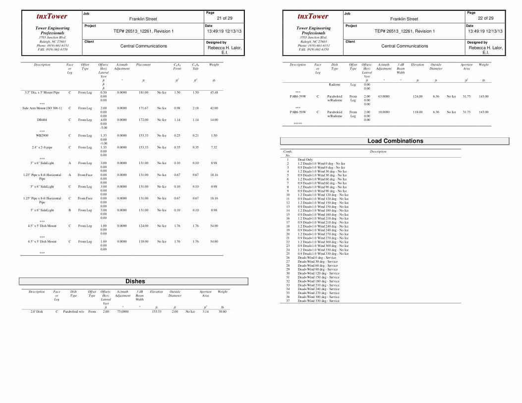
ttnnxxTToowweerr Job
Franklin Street
Page
21 of 29
Tower Engineering
Professionals
3703 Junction Blvd.
Project
TEP# 26513_12261, Revision 1
Date
13:49:19 12/13/13
Raleigh, NC 27603
Phone: (919) 661-6351
FAX: (919) 661-6350
Client
Central Communications Designed by
Rebecca H. Lalor, E.I.
Description Face
or
Leg
Offset
Type
Offsets:
Horz
Lateral
Vert
ft
ft
ft
Azimuth
Adjustment
°
Placement
ft
CAAA
Front
ft2
CAAA
Side
ft2
Weight
lb
3.5'' Dia. x 5' Mount Pipe C From Leg 0.50
0.00 0.00
0.0000 181.00 No Ice 1.50 1.50 45.48
***
Side Arm Mount [SO 306-1] C From Leg 2.00
0.00
0.00
0.0000 171.67 No Ice 0.98 2.18 42.00
DB404 C From Leg 4.00
0.00
-5.00
0.0000 172.00 No Ice 1.14 1.14 14.00
*** WB2900 C From Leg 1.33
0.00 -1.00
0.0000 153.33 No Ice 0.25 0.21 1.50
2.4'' x 2-ft pipe C From Leg 1.33
0.00 0.00
0.0000 153.33 No Ice 0.35 0.35 7.32
***
3'' x 6'' SideLight A From Leg 3.00
0.00 0.00
0.0000 131.00 No Ice 0.10 0.10 0.98
1.25'' Pipe x 8-ft Horizontal Pipe
A From Face 0.00 0.00
0.00
0.0000 131.00 No Ice 0.67 0.67 18.16
3'' x 6'' SideLight C From Leg 3.00
0.00 0.00
0.0000 131.00 No Ice 0.10 0.10 0.98
1.25'' Pipe x 8-ft Horizontal
Pipe
C From Face 0.00
0.00
0.00
0.0000 131.00 No Ice 0.67 0.67 18.16
3'' x 6'' SideLight B From Leg 3.00 0.00
0.00
0.0000 131.00 No Ice 0.10 0.10 0.98
***
4.5'' x 5' Dish Mount C From Leg 1.00 0.00
0.00
0.0000 124.00 No Ice 1.76 1.76 54.00
***
4.5'' x 5' Dish Mount C From Leg 1.00
0.00 0.00
0.0000 118.00 No Ice 1.76 1.76 54.00
***
Dishes
Description Face
or
Leg
Dish
Type
Offset
Type
Offsets:
Horz
Lateral
Vert
ft
Azimuth
Adjustment
°
3 dB
Beam
Width
°
Elevation
ft
Outside
Diameter
ft
Aperture
Area
ft2
Weight
lb
2.0' Dish C Paraboloid w/o From 2.00 75.0000 153.33 2.00 No Ice 3.14 30.00
ttnnxxTToowweerr Job
Franklin Street
Page
22 of 29
Tower Engineering
Professionals
3703 Junction Blvd.
Project
TEP# 26513_12261, Revision 1
Date
13:49:19 12/13/13
Raleigh, NC 27603
Phone: (919) 661-6351
FAX: (919) 661-6350
Client
Central Communications Designed by
Rebecca H. Lalor, E.I.
Description Face
or
Leg
Dish
Type
Offset
Type
Offsets:
Horz
Lateral
Vert
ft
Azimuth
Adjustment
°
3 dB
Beam
Width
°
Elevation
ft
Outside
Diameter
ft
Aperture
Area
ft2
Weight
lb
Radome Leg 0.00
0.00
***
PAR6-59W C Paraboloid w/Radome
From Leg
2.00 0.00
0.00
63.0000 124.00 6.36 No Ice 31.75 143.00
***
PAR6-59W C Paraboloid
w/Radome
From
Leg
2.00
0.00 0.00
10.0000 118.00 6.36 No Ice 31.75 143.00
*****
Load Combinations
Comb.
No.
Description
1 Dead Only
2 1.2 Dead+1.0 Wind 0 deg - No Ice
3 0.9 Dead+1.0 Wind 0 deg - No Ice
4 1.2 Dead+1.0 Wind 30 deg - No Ice 5 0.9 Dead+1.0 Wind 30 deg - No Ice
6 1.2 Dead+1.0 Wind 60 deg - No Ice
7 0.9 Dead+1.0 Wind 60 deg - No Ice
8 1.2 Dead+1.0 Wind 90 deg - No Ice
9 0.9 Dead+1.0 Wind 90 deg - No Ice 10 1.2 Dead+1.0 Wind 120 deg - No Ice
11 0.9 Dead+1.0 Wind 120 deg - No Ice
12 1.2 Dead+1.0 Wind 150 deg - No Ice
13 0.9 Dead+1.0 Wind 150 deg - No Ice 14 1.2 Dead+1.0 Wind 180 deg - No Ice
15 0.9 Dead+1.0 Wind 180 deg - No Ice 16 1.2 Dead+1.0 Wind 210 deg - No Ice
17 0.9 Dead+1.0 Wind 210 deg - No Ice
18 1.2 Dead+1.0 Wind 240 deg - No Ice 19 0.9 Dead+1.0 Wind 240 deg - No Ice
20 1.2 Dead+1.0 Wind 270 deg - No Ice
21 0.9 Dead+1.0 Wind 270 deg - No Ice
22 1.2 Dead+1.0 Wind 300 deg - No Ice 23 0.9 Dead+1.0 Wind 300 deg - No Ice
24 1.2 Dead+1.0 Wind 330 deg - No Ice 25 0.9 Dead+1.0 Wind 330 deg - No Ice
26 Dead+Wind 0 deg - Service
27 Dead+Wind 30 deg - Service
28 Dead+Wind 60 deg - Service 29 Dead+Wind 90 deg - Service
30 Dead+Wind 120 deg - Service
31 Dead+Wind 150 deg - Service
32 Dead+Wind 180 deg - Service
33 Dead+Wind 210 deg - Service 34 Dead+Wind 240 deg - Service
35 Dead+Wind 270 deg - Service
36 Dead+Wind 300 deg - Service
37 Dead+Wind 330 deg - Service
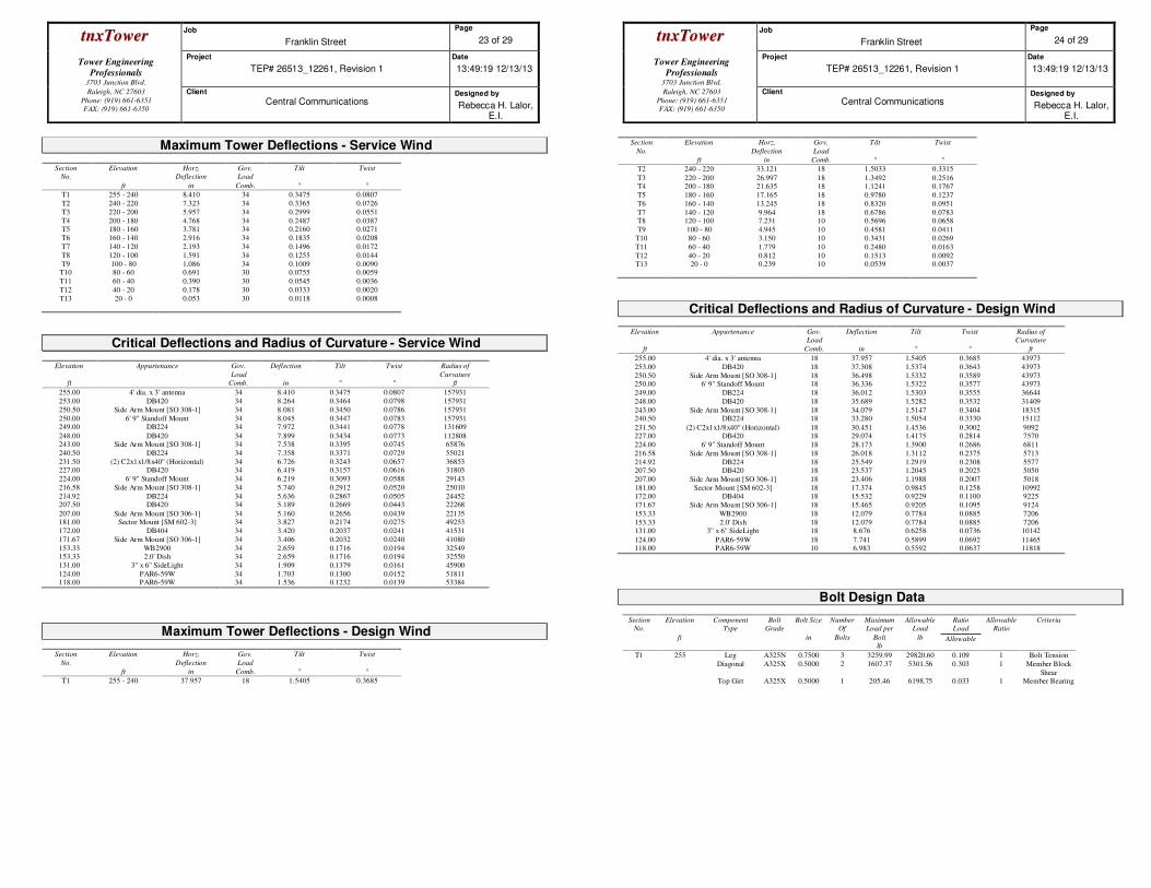
ttnnxxTToowweerr Job
Franklin Street
Page
23 of 29
Tower Engineering
Professionals
3703 Junction Blvd.
Project
TEP# 26513_12261, Revision 1
Date
13:49:19 12/13/13
Raleigh, NC 27603
Phone: (919) 661-6351
FAX: (919) 661-6350
Client
Central Communications Designed by
Rebecca H. Lalor, E.I.
Maximum Tower Deflections - Service Wind
Section
No.
Elevation
ft
Horz.
Deflection
in
Gov.
Load
Comb.
Tilt
°
Twist
°
T1 255 - 240 8.410 34 0.3475 0.0807
T2 240 - 220 7.323 34 0.3365 0.0726
T3 220 - 200 5.957 34 0.2999 0.0551
T4 200 - 180 4.768 34 0.2487 0.0387 T5 180 - 160 3.781 34 0.2160 0.0271
T6 160 - 140 2.916 34 0.1835 0.0208
T7 140 - 120 2.193 34 0.1496 0.0172
T8 120 - 100 1.591 34 0.1255 0.0144
T9 100 - 80 1.086 34 0.1009 0.0090 T10 80 - 60 0.691 30 0.0755 0.0059
T11 60 - 40 0.390 30 0.0545 0.0036
T12 40 - 20 0.178 30 0.0333 0.0020
T13 20 - 0 0.053 30 0.0118 0.0008
Critical Deflections and Radius of Curvature - Service Wind
Elevation
ft
Appurtenance Gov.
Load
Comb.
Deflection
in
Tilt
°
Twist
°
Radius of
Curvature
ft
255.00 4' dia. x 3' antenna 34 8.410 0.3475 0.0807 157931
253.00 DB420 34 8.264 0.3464 0.0798 157931
250.50 Side Arm Mount [SO 308-1] 34 8.081 0.3450 0.0786 157931
250.00 6' 9'' Standoff Mount 34 8.045 0.3447 0.0783 157931 249.00 DB224 34 7.972 0.3441 0.0778 131609
248.00 DB420 34 7.899 0.3434 0.0773 112808 243.00 Side Arm Mount [SO 308-1] 34 7.538 0.3395 0.0745 65876
240.50 DB224 34 7.358 0.3371 0.0729 55021
231.50 (2) C2x1x1/8x40'' (Horizontal) 34 6.726 0.3243 0.0657 36853 227.00 DB420 34 6.419 0.3157 0.0616 31803
224.00 6' 9'' Standoff Mount 34 6.219 0.3093 0.0588 29143
216.58 Side Arm Mount [SO 308-1] 34 5.740 0.2912 0.0520 25010
214.92 DB224 34 5.636 0.2867 0.0505 24452 207.50 DB420 34 5.189 0.2669 0.0443 22268
207.00 Side Arm Mount [SO 306-1] 34 5.160 0.2656 0.0439 22135 181.00 Sector Mount [SM 602-3] 34 3.827 0.2174 0.0275 49253
172.00 DB404 34 3.420 0.2037 0.0241 41531
171.67 Side Arm Mount [SO 306-1] 34 3.406 0.2032 0.0240 41080
153.33 WB2900 34 2.659 0.1716 0.0194 32549 153.33 2.0' Dish 34 2.659 0.1716 0.0194 32550
131.00 3'' x 6'' SideLight 34 1.909 0.1379 0.0161 45900
124.00 PAR6-59W 34 1.703 0.1300 0.0152 51811 118.00 PAR6-59W 34 1.536 0.1232 0.0139 53384
Maximum Tower Deflections - Design Wind
Section
No.
Elevation
ft
Horz.
Deflection
in
Gov.
Load
Comb.
Tilt
°
Twist
°
T1 255 - 240 37.957 18 1.5405 0.3685
ttnnxxTToowweerr Job
Franklin Street
Page
24 of 29
Tower Engineering
Professionals
3703 Junction Blvd.
Project
TEP# 26513_12261, Revision 1
Date
13:49:19 12/13/13
Raleigh, NC 27603
Phone: (919) 661-6351
FAX: (919) 661-6350
Client
Central Communications Designed by
Rebecca H. Lalor, E.I.
Section
No.
Elevation
ft
Horz.
Deflection
in
Gov.
Load
Comb.
Tilt
°
Twist
°
T2 240 - 220 33.121 18 1.5033 0.3315
T3 220 - 200 26.997 18 1.3492 0.2516 T4 200 - 180 21.635 18 1.1241 0.1767
T5 180 - 160 17.165 18 0.9780 0.1237
T6 160 - 140 13.245 18 0.8320 0.0951
T7 140 - 120 9.964 18 0.6786 0.0783 T8 120 - 100 7.231 10 0.5696 0.0658
T9 100 - 80 4.945 10 0.4581 0.0411
T10 80 - 60 3.150 10 0.3431 0.0269
T11 60 - 40 1.779 10 0.2480 0.0163
T12 40 - 20 0.812 10 0.1513 0.0092 T13 20 - 0 0.239 10 0.0539 0.0037
Critical Deflections and Radius of Curvature - Design Wind
Elevation
ft
Appurtenance Gov.
Load
Comb.
Deflection
in
Tilt
°
Twist
°
Radius of
Curvature
ft
255.00 4' dia. x 3' antenna 18 37.957 1.5405 0.3685 43973
253.00 DB420 18 37.308 1.5374 0.3643 43973
250.50 Side Arm Mount [SO 308-1] 18 36.498 1.5332 0.3589 43973 250.00 6' 9'' Standoff Mount 18 36.336 1.5322 0.3577 43973
249.00 DB224 18 36.012 1.5303 0.3555 36644
248.00 DB420 18 35.689 1.5282 0.3532 31409
243.00 Side Arm Mount [SO 308-1] 18 34.079 1.5147 0.3404 18315 240.50 DB224 18 33.280 1.5054 0.3330 15112
231.50 (2) C2x1x1/8x40'' (Horizontal) 18 30.451 1.4536 0.3002 9092 227.00 DB420 18 29.074 1.4175 0.2814 7570
224.00 6' 9'' Standoff Mount 18 28.173 1.3900 0.2686 6811
216.58 Side Arm Mount [SO 308-1] 18 26.018 1.3112 0.2375 5713
214.92 DB224 18 25.549 1.2919 0.2308 5577 207.50 DB420 18 23.537 1.2045 0.2025 5050
207.00 Side Arm Mount [SO 306-1] 18 23.406 1.1988 0.2007 5018
181.00 Sector Mount [SM 602-3] 18 17.374 0.9845 0.1258 10992 172.00 DB404 18 15.532 0.9229 0.1100 9225
171.67 Side Arm Mount [SO 306-1] 18 15.465 0.9205 0.1095 9124
153.33 WB2900 18 12.079 0.7784 0.0885 7206
153.33 2.0' Dish 18 12.079 0.7784 0.0885 7206 131.00 3'' x 6'' SideLight 18 8.676 0.6258 0.0736 10142
124.00 PAR6-59W 18 7.741 0.5899 0.0692 11465 118.00 PAR6-59W 10 6.983 0.5592 0.0637 11818
Bolt Design Data
Section
No.
Elevation
ft
Component
Type
Bolt
Grade
Bolt Size
in
Number
Of
Bolts
Maximum
Load per
Bolt
lb
Allowable
Load
lb
Ratio
Load
Allowable
Allowable
Ratio
Criteria
T1 255 Leg A325N 0.7500 3 3259.99 29820.60 0.109 1 Bolt Tension
Diagonal A325X 0.5000 2 1607.37 5301.56 0.303 1 Member Block
Shear Top Girt A325X 0.5000 1 205.46 6198.75 0.033 1 Member Bearing
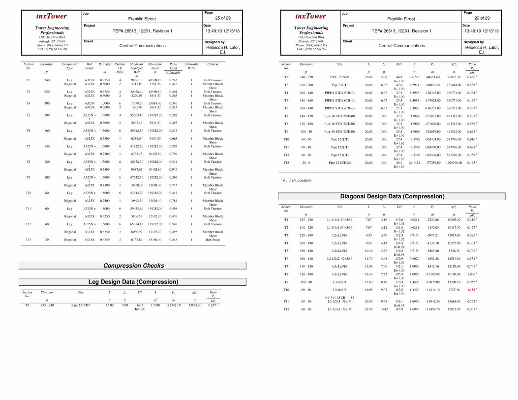
ttnnxxTToowweerr Job
Franklin Street
Page
25 of 29
Tower Engineering
Professionals
3703 Junction Blvd.
Project
TEP# 26513_12261, Revision 1
Date
13:49:19 12/13/13
Raleigh, NC 27603
Phone: (919) 661-6351
FAX: (919) 661-6350
Client
Central Communications Designed by
Rebecca H. Lalor, E.I.
Section
No.
Elevation
ft
Component
Type
Bolt
Grade
Bolt Size
in
Number
Of
Bolts
Maximum
Load per
Bolt
lb
Allowable
Load
lb
Ratio
Load
Allowable
Allowable
Ratio
Criteria
T2 240 Leg A325N 0.8750 4 9856.13 40589.10 0.243 1 Bolt Tension Diagonal A325X 0.5000 2 2215.89 5301.56 0.418 1 Member Block
Shear
T3 220 Leg A325N 0.8750 4 20058.40 40589.10 0.494 1 Bolt Tension
Diagonal A325X 0.5000 2 3270.06 5811.33 0.563 1 Member Block Shear
T4 200 Leg A325N 1.0000 6 17998.50 53014.40 0.340 1 Bolt Tension
Diagonal A325X 0.5000 2 1935.03 5811.33 0.333 1 Member Block
Shear
T5 180 Leg A325N > 1
1.5000 4 35603.10 119282.00 0.298 1 Bolt Tension
Diagonal A325X 0.5000 2 2867.46 5811.33 0.493 1 Member Block
Shear
T6 160 Leg A325N > 1
1.5000 6 29612.50 119282.00 0.248 1 Bolt Tension
Diagonal A325X 0.7500 1 6236.04 9404.30 0.663 1 Member Block Shear
T7 140 Leg A325N >
1
1.5000 6 34822.70 119282.00 0.292 1 Bolt Tension
Diagonal A325X 0.7500 1 8332.45 10423.80 0.799 1 Member Block
Shear
T8 120 Leg A325N >
1
1.5000 6 40978.30 119282.00 0.344 1 Bolt Tension
Diagonal A325X 0.7500 1 9887.67 10423.80 0.949 1 Member Block
Shear T9 100 Leg A325N >
1
1.5000 6 47242.70 119282.00 0.396 1 Bolt Tension
Diagonal A325X 0.7500 1 10360.00 13898.40 0.745 1 Member Block
Shear T10 80 Leg A325N >
1
1.5000 6 53343.20 119282.00 0.447 1 Bolt Tension
Diagonal A325X 0.7500 1 10893.30 13898.40 0.784 1 Member Block
Shear
T11 60 Leg A325N > 1
1.5000 6 59433.60 119282.00 0.498 1 Bolt Tension
Diagonal A325X 0.6250 2 5806.53 12192.20 0.476 1 Member Block
Shear
T12 40 Leg A325N > 1
1.5000 6 65384.10 119282.00 0.548 1 Bolt Tension
Diagonal A325X 0.6250 2 6030.97 12192.20 0.495 1 Member Block
Shear
T13 20 Diagonal A325X 0.6250 2 6732.84 15186.40 0.443 1 Bolt Shear
Compression Checks
Leg Design Data (Compression)
Section
No.
Elevation
ft
Size
L
ft
Lu
ft
Kl/r
A
in2
Pu
lb
φPn
lb
Ratio
Pu
φPn
T1 255 - 240 Pipe 2.5 STD 15.00 5.00 63.3
K=1.00
1.7040 -12742.10 53865.90 0.237 1
ttnnxxTToowweerr Job
Franklin Street
Page
26 of 29
Tower Engineering
Professionals
3703 Junction Blvd.
Project
TEP# 26513_12261, Revision 1
Date
13:49:19 12/13/13
Raleigh, NC 27603
Phone: (919) 661-6351
FAX: (919) 661-6350
Client
Central Communications Designed by
Rebecca H. Lalor, E.I.
Section
No.
Elevation
ft
Size
L
ft
Lu
ft
Kl/r
A
in2
Pu
lb
φPn
lb
Ratio
Pu
φPn
T2 240 - 220 PIPE 3.5 STD 20.00 5.00 44.9
K=1.00
2.6795 -44551.60 96872.30 0.460 1
T3 220 - 200 Pipe 5 STD 20.00 6.67 42.6 K=1.00
4.2974 -88058.30 157444.00 0.559 1
T4 200 - 180 PIPE 8 STD (SCH40) 20.02 6.67 27.3 K=1.00
8.3993 -120397.00 330771.00 0.364 1
T5 180 - 160 PIPE 8 STD (SCH40) 20.02 6.67 27.3
K=1.00
8.3993 -157923.00 330771.00 0.477 1
T6 160 - 140 PIPE 8 STD (SCH40) 20.02 6.67 27.3
K=1.00
8.3993 -196255.00 330771.00 0.593 1
T7 140 - 120 Pipe 10 STD (SCH40) 20.02 10.01 32.5
K=1.00
11.9656 -231031.00 461312.00 0.501 1
T8 120 - 100 Pipe 10 STD (SCH40) 20.02 10.01 32.5
K=1.00
11.9656 -271670.00 461312.00 0.589 1
T9 100 - 80 Pipe 10 STD (SCH40) 20.02 10.01 32.5
K=1.00
11.9656 -312679.00 461312.00 0.678 1
T10 80 - 60 Pipe 12 STD 20.02 10.01 27.4
K=1.00
14.5790 -353403.00 573746.00 0.616 1
T11 60 - 40 Pipe 12 STD 20.02 10.01 27.4
K=1.00
14.5790 -394550.00 573746.00 0.688 1
T12 40 - 20 Pipe 12 STD 20.02 10.01 27.4
K=1.00
14.5790 -435406.00 573746.00 0.759 1
T13 20 - 0 Pipe 12 SCH 80 20.02 10.01 28.1
K=1.00
26.1424 -477259.00 1026190.00 0.465 1
1 P u / φPn controls
Diagonal Design Data (Compression)
Section
No.
Elevation
ft
Size
L
ft
Lu
ft
Kl/r
A
in2
Pu
lb
φPn
lb
Ratio
Pu
φPn
T1 255 - 240 L1 3/4x1 3/4x3/16 7.07 3.19 113.6
K=1.02
0.6211 -3222.66 10205.20 0.316 1
T2 240 - 220 L1 3/4x1 3/4x3/16 7.07 3.12 111.8 K=1.02
0.6211 -4452.03 10417.70 0.427 1
T3 220 - 200 L2x2x3/16 8.33 3.60 112.3
K=1.02
0.7150 -6979.21 11924.80 0.585 1
T4 200 - 180 L2x2x3/16 9.24 4.12 124.3
K=0.99
0.7150 -4138.10 10275.80 0.403 1
T5 180 - 160 L2x2x3/16 10.46 4.77 139.2
K=0.96
0.7150 -5885.40 8336.13 0.706 1
T6 160 - 140 L2 1/2x2 1/2x3/16 11.79 5.48 132.9
K=1.00
0.9020 -6392.38 11534.80 0.554 1
T7 140 - 120 L3x3x3/16 15.06 7.06 142.1
K=1.00
1.0900 -8542.10 12189.90 0.701 1
T8 120 - 100 L3x3x3/16 16.34 7.72 155.4
K=1.00
1.0900 -10196.90 10196.90 1.000 1
T9 100 - 80 L3x3x1/4 17.69 8.40 170.4
K=1.00
1.4400 -10675.00 11209.10 0.952 1
T10 80 - 60 L3x3x1/4 19.08 9.02 182.8
K=1.00
1.4400 -11214.10 9737.46 1.152 1
4.9-3 (1.15 CR) - 185 T11 60 - 40 L3 1/2x3 1/2x1/4 20.52 9.68 156.1
K=0.93
1.6900 -11942.30 15665.80 0.762 1
T12 40 - 20 L3 1/2x3 1/2x1/4 21.99 10.42 165.9 1.6900 -12498.70 13872.90 0.901 1
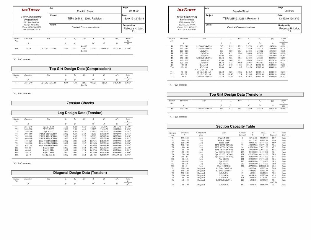
ttnnxxTToowweerr Job
Franklin Street
Page
27 of 29
Tower Engineering
Professionals
3703 Junction Blvd.
Project
TEP# 26513_12261, Revision 1
Date
13:49:19 12/13/13
Raleigh, NC 27603
Phone: (919) 661-6351
FAX: (919) 661-6350
Client
Central Communications Designed by
Rebecca H. Lalor, E.I.
Section
No.
Elevation
ft
Size
L
ft
Lu
ft
Kl/r
A
in2
Pu
lb
φPn
lb
Ratio
Pu
φPn
K=0.92
T13 20 - 0 L3 1/2x3 1/2x5/16 23.49 11.17 176.7
K=0.91
2.0900 -13465.70 15125.40 0.890 1
1 P u / φPn controls
Top Girt Design Data (Compression)
Section
No.
Elevation
ft
Size
L
ft
Lu
ft
Kl/r
A
in2
Pu
lb
φPn
lb
Ratio
Pu
φPn
T1 255 - 240 L2 1/2x2 1/2x3/16 5.00 4.55 115.2
K=1.04
0.9020 -226.26 14536.40 0.016 1
1 P u / φPn controls
Tension Checks
Leg Design Data (Tension)
Section
No.
Elevation
ft
Size
L
ft
Lu
ft
Kl/r
A
in2
Pu
lb
φPn
lb
Ratio
Pu
φPn
T1 255 - 240 Pipe 2.5 STD 15.00 5.00 63.3 1.7040 9779.96 70547.70 0.139 1
T2 240 - 220 PIPE 3.5 STD 20.00 5.00 44.9 2.6795 39424.50 110933.00 0.355 1
T3 220 - 200 Pipe 5 STD 20.00 6.67 42.6 4.2974 80233.40 177914.00 0.451 1
T4 200 - 180 PIPE 8 STD (SCH40) 20.02 6.67 27.3 8.3993 107991.00 347729.00 0.311 1
T5 180 - 160 PIPE 8 STD (SCH40) 20.02 6.67 27.3 8.3993 142412.00 347729.00 0.410 1
T6 160 - 140 PIPE 8 STD (SCH40) 20.02 6.67 27.3 8.3993 177675.00 347729.00 0.511 1
T7 140 - 120 Pipe 10 STD (SCH40) 20.02 10.01 32.5 11.9656 208936.00 495377.00 0.422 1
T8 120 - 100 Pipe 10 STD (SCH40) 20.02 10.01 32.5 11.9656 245870.00 495377.00 0.496 1
T9 100 - 80 Pipe 10 STD (SCH40) 20.02 10.01 32.5 11.9656 283456.00 495377.00 0.572 1
T10 80 - 60 Pipe 12 STD 20.02 10.01 27.4 14.5790 320059.00 603569.00 0.530 1
T11 60 - 40 Pipe 12 STD 20.02 10.01 27.4 14.5790 356601.00 603569.00 0.591 1
T12 40 - 20 Pipe 12 STD 20.02 10.01 27.4 14.5790 392304.00 603569.00 0.650 1
T13 20 - 0 Pipe 12 SCH 80 20.02 10.01 28.1 26.1424 426814.00 1082300.00 0.394 1
1 P u / φPn controls
Diagonal Design Data (Tension)
Section
No.
Elevation
ft
Size
L
ft
Lu
ft
Kl/r
A
in2
Pu
lb
φPn
lb
Ratio
Pu
φPn
ttnnxxTToowweerr Job
Franklin Street
Page
28 of 29
Tower Engineering
Professionals
3703 Junction Blvd.
Project
TEP# 26513_12261, Revision 1
Date
13:49:19 12/13/13
Raleigh, NC 27603
Phone: (919) 661-6351
FAX: (919) 661-6350
Client
Central Communications Designed by
Rebecca H. Lalor, E.I.
Section
No.
Elevation
ft
Size
L
ft
Lu
ft
Kl/r
A
in2
Pu
lb
φPn
lb
Ratio
Pu
φPn
T1 255 - 240 L1 3/4x1 3/4x3/16 7.07 3.19 75.2 0.3779 3214.73 16439.90 0.196 1
T2 240 - 220 L1 3/4x1 3/4x3/16 7.07 3.12 73.7 0.3779 4431.79 16439.90 0.270 1
T3 220 - 200 L2x2x3/16 8.33 3.60 73.5 0.4484 6540.12 19503.60 0.335 1
T4 200 - 180 L2x2x3/16 9.24 4.12 83.6 0.4484 3870.06 19503.60 0.198 1
T5 180 - 160 L2x2x3/16 10.04 4.56 92.1 0.4484 5734.92 19503.60 0.294 1
T6 160 - 140 L2 1/2x2 1/2x3/16 11.34 5.26 83.4 0.5535 6236.04 24075.20 0.259 1
T7 140 - 120 L3x3x3/16 15.06 7.06 92.1 0.6945 8332.45 30208.70 0.276 1
T8 120 - 100 L3x3x3/16 16.34 7.72 100.5 0.6945 9887.67 30208.70 0.327 1
T9 100 - 80 L3x3x1/4 17.69 8.40 110.3 0.9159 10360.00 39843.30 0.260 1
T10 80 - 60 L3x3x1/4 19.08 9.02 118.2 0.9159 10893.30 39843.30 0.273 1
4.9-3 (1.11 CR) - 184
T11 60 - 40 L3 1/2x3 1/2x1/4 20.52 9.68 108.9 1.1269 11613.10 49019.10 0.237 1
T12 40 - 20 L3 1/2x3 1/2x1/4 21.99 10.42 117.1 1.1269 12061.90 49019.10 0.246 1
T13 20 - 0 L3 1/2x3 1/2x5/16 23.49 11.17 126.5 1.3917 13152.40 60539.80 0.217 1
1 P u / φPn controls
Top Girt Design Data (Tension)
Section
No.
Elevation
ft
Size
L
ft
Lu
ft
Kl/r
A
in2
Pu
lb
φPn
lb
Ratio
Pu
φPn
T1 255 - 240 L2 1/2x2 1/2x3/16 5.00 4.55 73.4 0.5886 205.46 25604.50 0.008 1
1 P u / φPn controls
Section Capacity Table
Section
No.
Elevation
ft
Component
Type
Size Critical
Element
P
lb
øPallow
lb
%
Capacity
Pass
Fail
T1 255 - 240 Leg Pipe 2.5 STD 1 -12742.10 53865.90 23.7 Pass
T2 240 - 220 Leg PIPE 3.5 STD 25 -44551.60 96872.30 46.0 Pass
T3 220 - 200 Leg Pipe 5 STD 52 -88058.30 157444.00 55.9 Pass
T4 200 - 180 Leg PIPE 8 STD (SCH40) 73 -120397.00 330771.00 36.4 Pass T5 180 - 160 Leg PIPE 8 STD (SCH40) 94 -157923.00 330771.00 47.7 Pass
T6 160 - 140 Leg PIPE 8 STD (SCH40) 115 -196255.00 330771.00 59.3 Pass
T7 140 - 120 Leg Pipe 10 STD (SCH40) 136 -231031.00 461312.00 50.1 Pass
T8 120 - 100 Leg Pipe 10 STD (SCH40) 151 -271670.00 461312.00 58.9 Pass
T9 100 - 80 Leg Pipe 10 STD (SCH40) 166 -312679.00 461312.00 67.8 Pass T10 80 - 60 Leg Pipe 12 STD 181 -353403.00 573746.00 61.6 Pass
T11 60 - 40 Leg Pipe 12 STD 196 -394550.00 573746.00 68.8 Pass
T12 40 - 20 Leg Pipe 12 STD 212 -435406.00 573746.00 75.9 Pass
T13 20 - 0 Leg Pipe 12 SCH 80 227 -477259.00 1026190.00 46.5 Pass T1 255 - 240 Diagonal L1 3/4x1 3/4x3/16 11 -3222.66 10205.20 31.6 Pass
T2 240 - 220 Diagonal L1 3/4x1 3/4x3/16 38 -4452.03 10417.70 42.7 Pass
T3 220 - 200 Diagonal L2x2x3/16 59 -6979.21 11924.80 58.5 Pass
T4 200 - 180 Diagonal L2x2x3/16 80 -4138.10 10275.80 40.3 Pass T5 180 - 160 Diagonal L2x2x3/16 101 -5885.40 8336.13 70.6 Pass
T6 160 - 140 Diagonal L2 1/2x2 1/2x3/16 123 -6392.38 11534.80 55.4
66.3 (b)
Pass
T7 140 - 120 Diagonal L3x3x3/16 140 -8542.10 12189.90 70.1 Pass
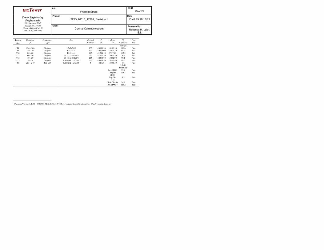
ttnnxxTToowweerr Job
Franklin Street
Page
29 of 29
Tower Engineering
Professionals
3703 Junction Blvd.
Project
TEP# 26513_12261, Revision 1
Date
13:49:19 12/13/13
Raleigh, NC 27603
Phone: (919) 661-6351
FAX: (919) 661-6350
Client
Central Communications Designed by
Rebecca H. Lalor, E.I.
Section
No.
Elevation
ft
Component
Type
Size Critical
Element
P
lb
øPallow
lb
%
Capacity
Pass
Fail
79.9 (b)
T8 120 - 100 Diagonal L3x3x3/16 155 -10196.90 10196.90 100.0 Pass
T9 100 - 80 Diagonal L3x3x1/4 170 -10675.00 11209.10 95.2 Pass
T10 80 - 60 Diagonal L3x3x1/4 185 -11214.10 9737.46 115.2 Fail T11 60 - 40 Diagonal L3 1/2x3 1/2x1/4 200 -11942.30 15665.80 76.2 Pass
T12 40 - 20 Diagonal L3 1/2x3 1/2x1/4 215 -12498.70 13872.90 90.1 Pass
T13 20 - 0 Diagonal L3 1/2x3 1/2x5/16 230 -13465.70 15125.40 89.0 Pass
T1 255 - 240 Top Girt L2 1/2x2 1/2x3/16 5 -226.26 14536.40 1.6 3.3 (b)
Pass
Summary
Leg (T12) 75.9 Pass
Diagonal
(T10)
115.2 Fail
Top Girt
(T1)
3.3 Pass
Bolt Checks 94.9 Pass
RATING = 115.2 Fail
Program Version 6.1.3.1 - 7/25/2013 File:T:/26513/12261_Franklin Street/Structural/Rev 1/tnx/Franklin Street.eri

December 13, 2013 255-ft Self Supporting Tower Structural Analysis Franklin Street TEP Project Number 26513_12261, Revision 1 Page 9
tnxTower Report - version 6.1.3.1
APPENDIX B
COAX CONFIGURATION
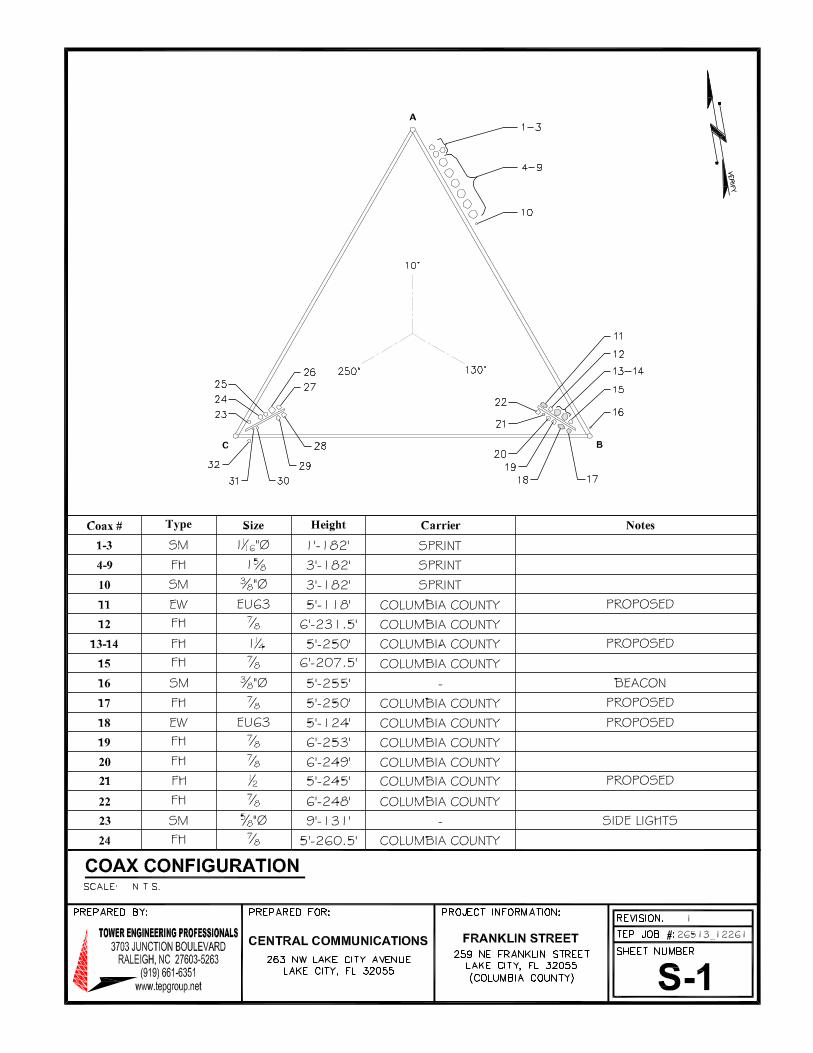
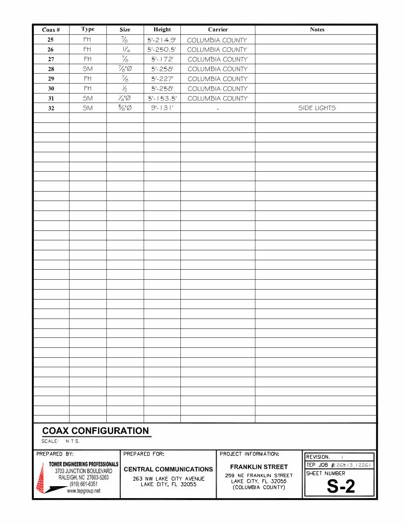
Columbia County APCO P25 700MHz Radio System Project RFP - 2017 - O
Vendor Questions and Answers
Lulu Tower Additional Information
FL COA# 30978
Date: April 25, 2016
Lawrence Wilson Tower Engineering ProfessionalsCentral Communications 326 Tryon Road263 NW Lake City Ave. Raleigh, NC 27603Lake City, FL 32055 (919) 661-6351(386) 758-1125 [email protected]
Subject: Structural Analysis Report
Carrier Designation: Columbia County ReconfigurationCarrier Site Name: LuluCarrier Site Number: Unknown
Engineering Firm Designation: TEP Project Number: 67865_45994
Site Data: Lulu Comm Center, Lulu, Columbia County, FL 32054Latitude 30° 6' 35.11'', Longitude -82° 29' 43.50''149 Foot - Monopole Tower
Dear Mr. Wilson,
Tower Engineering Professionals is pleased to submit this “Structural Analysis Report” to determine thestructural integrity of the above mentioned tower.
The purpose of the analysis is to determine acceptability of the tower stress level. Based on our analysis wehave determined the tower stress level for the structure, under the following load case, to be:
LC1: Existing + Proposed Equipment Sufficient CapacityNote: See Table 1 for the existing and proposed loading
This analysis has been performed in accordance with the ANSI/TIA-222-G-2-2009 Structural Standard forAntenna Supporting Structures and Antennas – Addendum 2 and the 2014 Florida Building Code, 5th Edition,based upon an ultimate 3-second gust wind speed of 120 mph converted to a nominal 3-second gust windspeed of 93 mph per Section 1609.3.1 as required for use in the TIA-222-G Standard per Exception #5 ofSection 1609.1.1. Exposure Category C, with a maximum Topographic Factor Kzt, of 1.0 and Risk Category IIwere used in this analysis.
All modifications and equipment proposed in this report shall be installed in accordance with the appurtenanceslisted in Table 1 and the attached drawings for the determined available structural capacity to be effective.
We at Tower Engineering Professionals appreciate the opportunity of providing our continuing professionalservices to you and Central Communications. If you have any questions or need further assistance on this orany other projects please give us a call.
Structural analysis prepared by: Sean M. Rock, E.I.
Respectfully submitted by:
Graham M. Andres, P.E.
StructureCapacity Controlling Component
54.1% Pole (L3) : 47.0033 to 0 ft.
April 25, 2016149-ft Monopole Tower Structural Analysis LuluTEP Project Number 67865_45994, Revision 0 Page 2
tnxTower Report - version 7.0.5.1
TABLE OF CONTENTS
1) INTRODUCTION
2) ANALYSIS CRITERIATable 1 - Existing and Proposed Antenna and Cable InformationTable 2 - Design Antenna and Cable Information
3) ANALYSIS PROCEDURETable 3 - Documents Provided3.1) Analysis Method3.2) Assumptions
4) ANALYSIS RESULTSTable 4 - Section Capacity (Summary)Table 5 - Tower Component Stresses vs. CapacityTable 6 - Dish Twist/Sway Results for 60 mph Service Wind Speed4.1) Recommendations
5) APPENDIX AtnxTower Output
6) APPENDIX BCoax Configuration
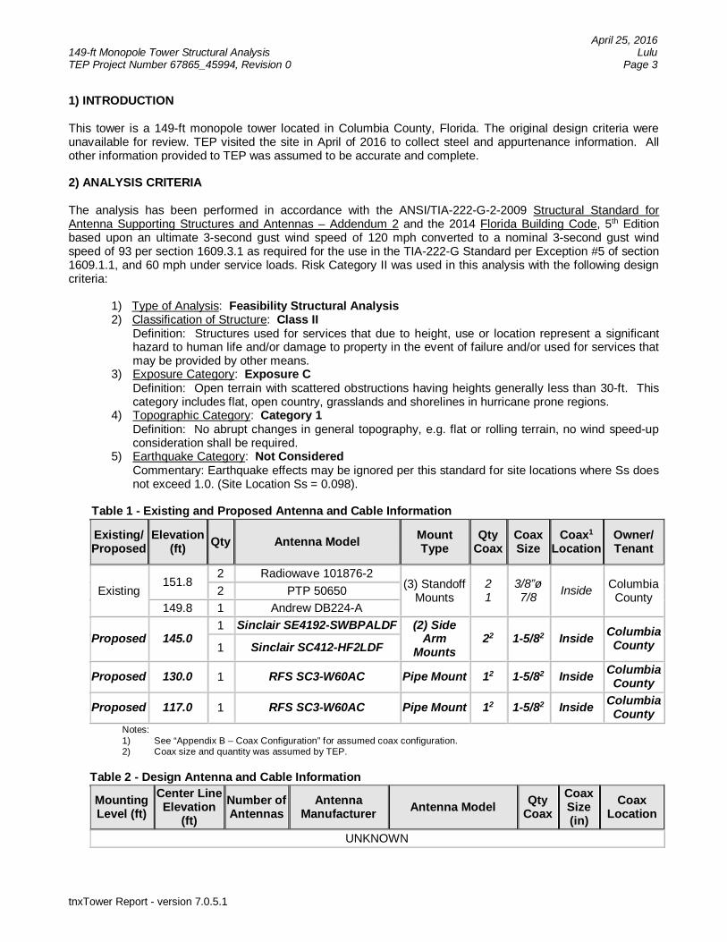
April 25, 2016149-ft Monopole Tower Structural Analysis LuluTEP Project Number 67865_45994, Revision 0 Page 3
tnxTower Report - version 7.0.5.1
1) INTRODUCTION
This tower is a 149-ft monopole tower located in Columbia County, Florida. The original design criteria wereunavailable for review. TEP visited the site in April of 2016 to collect steel and appurtenance information. Allother information provided to TEP was assumed to be accurate and complete.
2) ANALYSIS CRITERIA
The analysis has been performed in accordance with the ANSI/TIA-222-G-2-2009 Structural Standard forAntenna Supporting Structures and Antennas – Addendum 2 and the 2014 Florida Building Code, 5th Editionbased upon an ultimate 3-second gust wind speed of 120 mph converted to a nominal 3-second gust windspeed of 93 per section 1609.3.1 as required for the use in the TIA-222-G Standard per Exception #5 of section1609.1.1, and 60 mph under service loads. Risk Category II was used in this analysis with the following designcriteria:
1) Type of Analysis: Feasibility Structural Analysis2) Classification of Structure: Class II Definition: Structures used for services that due to height, use or location represent a significant
hazard to human life and/or damage to property in the event of failure and/or used for services thatmay be provided by other means.
3) Exposure Category: Exposure CDefinition: Open terrain with scattered obstructions having heights generally less than 30-ft. Thiscategory includes flat, open country, grasslands and shorelines in hurricane prone regions.
4) Topographic Category: Category 1Definition: No abrupt changes in general topography, e.g. flat or rolling terrain, no wind speed-upconsideration shall be required.
5) Earthquake Category: Not ConsideredCommentary: Earthquake effects may be ignored per this standard for site locations where Ss doesnot exceed 1.0. (Site Location Ss = 0.098).
Table 1 - Existing and Proposed Antenna and Cable Information
Existing/Proposed
Elevation(ft) Qty Antenna Model Mount
TypeQty
CoaxCoaxSize
Coax1
LocationOwner/Tenant
Existing151.8
2 Radiowave 101876-2(3) Standoff
Mounts21
3/8”ø7/8 Inside Columbia
County2 PTP 50650149.8 1 Andrew DB224-A
Proposed 145.01 Sinclair SE4192-SWBPALDF (2) Side
ArmMounts
22 1-5/82 Inside ColumbiaCounty1 Sinclair SC412-HF2LDF
Proposed 130.0 1 RFS SC3-W60AC Pipe Mount 12 1-5/82 Inside ColumbiaCounty
Proposed 117.0 1 RFS SC3-W60AC Pipe Mount 12 1-5/82 Inside ColumbiaCounty
Notes:1) See “Appendix B – Coax Configuration” for assumed coax configuration.2) Coax size and quantity was assumed by TEP.
Table 2 - Design Antenna and Cable Information
MountingLevel (ft)
Center LineElevation
(ft)Number ofAntennas
AntennaManufacturer Antenna Model Qty
CoaxCoaxSize(in)
CoaxLocation
UNKNOWN
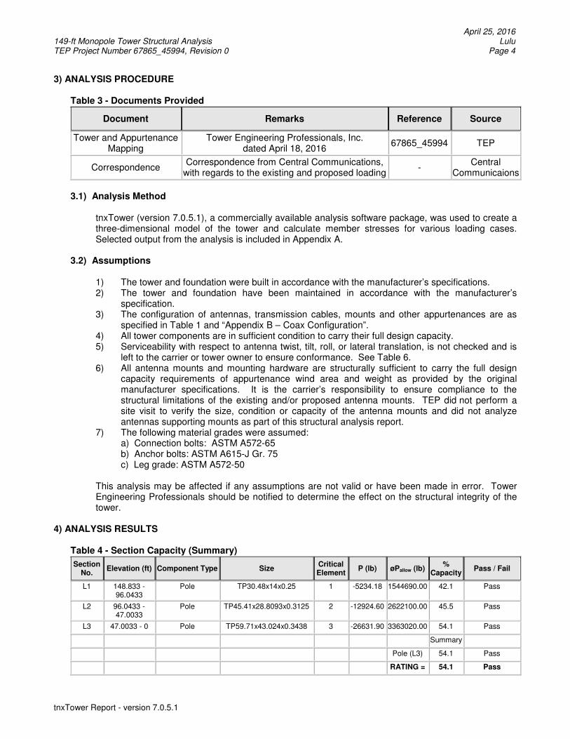
April 25, 2016 149-ft Monopole Tower Structural Analysis Lulu TEP Project Number 67865_45994, Revision 0 Page 4
tnxTower Report - version 7.0.5.1
3) ANALYSIS PROCEDURE
Table 3 - Documents Provided
Document Remarks Reference Source
Tower and Appurtenance Mapping
Tower Engineering Professionals, Inc. dated April 18, 2016
67865_45994 TEP
Correspondence Correspondence from Central Communications,
with regards to the existing and proposed loading -
Central Communicaions
3.1) Analysis Method
tnxTower (version 7.0.5.1), a commercially available analysis software package, was used to create a three-dimensional model of the tower and calculate member stresses for various loading cases. Selected output from the analysis is included in Appendix A.
3.2) Assumptions
1) The tower and foundation were built in accordance with the manufacturer’s specifications. 2) The tower and foundation have been maintained in accordance with the manufacturer’s
specification. 3) The configuration of antennas, transmission cables, mounts and other appurtenances are as
specified in Table 1 and “Appendix B – Coax Configuration”. 4) All tower components are in sufficient condition to carry their full design capacity. 5) Serviceability with respect to antenna twist, tilt, roll, or lateral translation, is not checked and is
left to the carrier or tower owner to ensure conformance. See Table 6. 6) All antenna mounts and mounting hardware are structurally sufficient to carry the full design
capacity requirements of appurtenance wind area and weight as provided by the original manufacturer specifications. It is the carrier’s responsibility to ensure compliance to the structural limitations of the existing and/or proposed antenna mounts. TEP did not perform a site visit to verify the size, condition or capacity of the antenna mounts and did not analyze antennas supporting mounts as part of this structural analysis report.
7) The following material grades were assumed: a) Connection bolts: ASTM A572-65 b) Anchor bolts: ASTM A615-J Gr. 75 c) Leg grade: ASTM A572-50 This analysis may be affected if any assumptions are not valid or have been made in error. Tower Engineering Professionals should be notified to determine the effect on the structural integrity of the tower.
4) ANALYSIS RESULTS
Table 4 - Section Capacity (Summary)
Section No. Elevation (ft) Component Type Size Critical
Element P (lb) øPallow (lb) % Capacity Pass / Fail
L1 148.833 - 96.0433
Pole TP30.48x14x0.25 1 -5234.18 1544690.00 42.1 Pass
L2 96.0433 - 47.0033
Pole TP45.41x28.8093x0.3125 2 -12924.60 2622100.00 45.5 Pass
L3 47.0033 - 0 Pole TP59.71x43.024x0.3438 3 -26631.90 3363020.00 54.1 Pass
Summary
Pole (L3) 54.1 Pass
RATING = 54.1 Pass
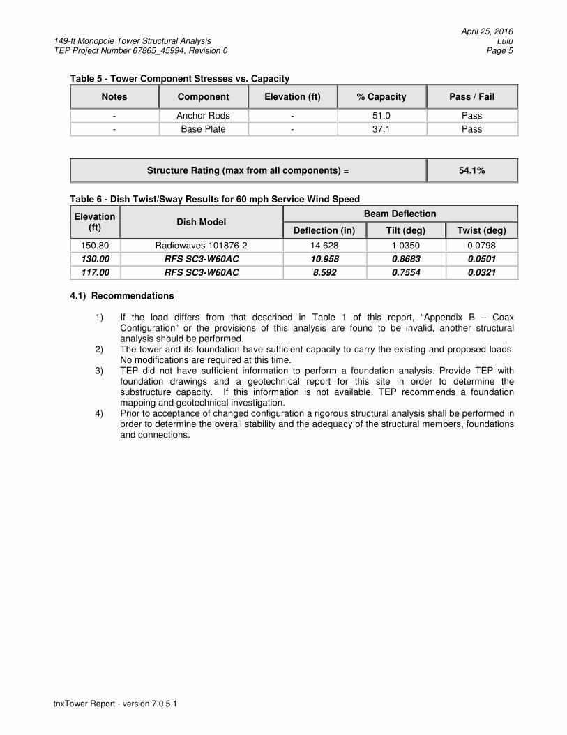
April 25, 2016 149-ft Monopole Tower Structural Analysis Lulu TEP Project Number 67865_45994, Revision 0 Page 5
tnxTower Report - version 7.0.5.1
Table 5 - Tower Component Stresses vs. Capacity
Notes Component Elevation (ft) % Capacity Pass / Fail
- Anchor Rods - 51.0 Pass
- Base Plate - 37.1 Pass
Structure Rating (max from all components) = 54.1%
Table 6 - Dish Twist/Sway Results for 60 mph Service Wind Speed
Elevation (ft)
Dish Model Beam Deflection
Deflection (in) Tilt (deg) Twist (deg)
150.80 Radiowaves 101876-2 14.628 1.0350 0.0798
130.00 RFS SC3-W60AC 10.958 0.8683 0.0501
117.00 RFS SC3-W60AC 8.592 0.7554 0.0321
4.1) Recommendations
1) If the load differs from that described in Table 1 of this report, “Appendix B – Coax
Configuration” or the provisions of this analysis are found to be invalid, another structural analysis should be performed.
2) The tower and its foundation have sufficient capacity to carry the existing and proposed loads. No modifications are required at this time.
3) TEP did not have sufficient information to perform a foundation analysis. Provide TEP with foundation drawings and a geotechnical report for this site in order to determine the substructure capacity. If this information is not available, TEP recommends a foundation mapping and geotechnical investigation.
4) Prior to acceptance of changed configuration a rigorous structural analysis shall be performed in order to determine the overall stability and the adequacy of the structural members, foundations and connections.
April 25, 2016 149-ft Monopole Tower Structural Analysis Lulu TEP Project Number 67865_45994, Revision 0 Page 6
tnxTower Report - version 7.0.5.1
APPENDIX A
TNXTOWER OUTPUT
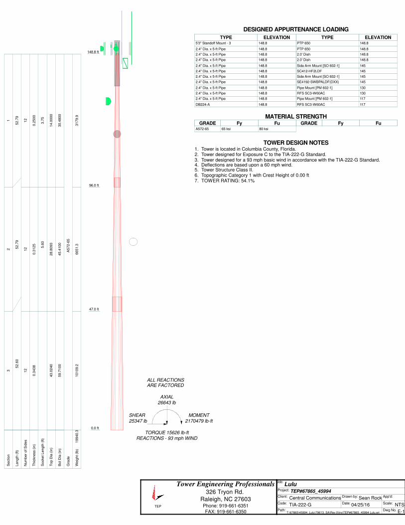
TEP
Tower Engineering Professionals 326 Tryon Rd.
Raleigh, NC 27603 Phone: 919-661-6351
FAX: 919-661-6350
Job: Lulu
Project: TEP#67865_45994 Client: Central Communications Drawn by: Sean Rock App'd:
Code: TIA-222-G Date: 04/25/16 Scale: NTS Path:
T:\67865\45994_Lulu\79613_SA\Rev 0\tnx\TEP#67865_45994 Lulu.eri Dwg No. E-1
148.8 ft
96.0 ft
47.0 ft
0.0 ft
REACTIONS - 93 mph WINDTORQUE 15626 lb-ft
25347 lb
SHEAR
2170479 lb-ft
MOMENT
26643 lbAXIAL
ARE FACTOREDALL REACTIONS
S
ectio
n1
23
L
en
gth
(ft)
52
.79
52
.79
52
.60
N
um
be
r o
f S
ide
s1
21
21
2
T
hic
kn
ess (
in)
0.2
50
00
.31
25
0.3
43
8
S
ocke
t L
en
gth
(ft)
3.7
55
.60
T
op
Dia
(in
)1
4.0
00
02
8.8
09
34
3.0
24
0
B
ot D
ia (
in)
30
.48
00
45
.41
00
59
.71
00
G
rad
eA
57
2-6
5
W
eig
ht (l
b)
31
79
.96
65
1.3
10
10
9.2
19
94
0.3
5'3" Standoff Mount - 3 148.8 2.4" Dia. x 5-ft Pipe 148.8 2.4" Dia. x 5-ft Pipe 148.8 2.4" Dia. x 5-ft Pipe 148.8 2.4" Dia. x 5-ft Pipe 148.8 2.4" Dia. x 5-ft Pipe 148.8 2.4" Dia. x 5-ft Pipe 148.8 2.4" Dia. x 5-ft Pipe 148.8 2.4" Dia. x 5-ft Pipe 148.8 2.4" Dia. x 5-ft Pipe 148.8 2.4" Dia. x 5-ft Pipe 148.8 DB224-A 148.8 PTP 650 148.8 PTP 650 148.8 2.0' Dish 148.8 2.0' Dish 148.8 Side Arm Mount [SO 602-1] 145 SC412-HF2LDF 145 Side Arm Mount [SO 602-1] 145 SE4192-SWBPALDF(DXX) 145 Pipe Mount [PM 602-1] 130 RFS SC3-W60AC 130 Pipe Mount [PM 602-1] 117 RFS SC3-W60AC 117DESIGNED APPURTENANCE LOADING
TYPE TYPEELEVATION ELEVATION 5'3" Standoff Mount - 3 148.8
2.4" Dia. x 5-ft Pipe 148.8
2.4" Dia. x 5-ft Pipe 148.8
2.4" Dia. x 5-ft Pipe 148.8
2.4" Dia. x 5-ft Pipe 148.8
2.4" Dia. x 5-ft Pipe 148.8
2.4" Dia. x 5-ft Pipe 148.8
2.4" Dia. x 5-ft Pipe 148.8
2.4" Dia. x 5-ft Pipe 148.8
2.4" Dia. x 5-ft Pipe 148.8
2.4" Dia. x 5-ft Pipe 148.8
DB224-A 148.8
PTP 650 148.8
PTP 650 148.8
2.0' Dish 148.8
2.0' Dish 148.8
Side Arm Mount [SO 602-1] 145
SC412-HF2LDF 145
Side Arm Mount [SO 602-1] 145
SE4192-SWBPALDF(DXX) 145
Pipe Mount [PM 602-1] 130
RFS SC3-W60AC 130
Pipe Mount [PM 602-1] 117
RFS SC3-W60AC 117
MATERIAL STRENGTHGRADE GRADEFy FyFu Fu
A572-65 65 ksi 80 ksi
TOWER DESIGN NOTES1. Tower is located in Columbia County, Florida.2. Tower designed for Exposure C to the TIA-222-G Standard.3. Tower designed for a 93 mph basic wind in accordance with the TIA-222-G Standard.4. Deflections are based upon a 60 mph wind.5. Tower Structure Class II.6. Topographic Category 1 with Crest Height of 0.00 ft7. TOWER RATING: 54.1%
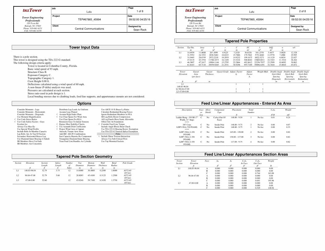
ttnnxxTToowweerr Job
Lulu
Page
1 of 8
Tower Engineering
Professionals
326 Tryon Rd.
Project
TEP#67865_45994
Date
09:52:00 04/25/16
Raleigh, NC 27603
Phone: 919-661-6351
FAX: 919-661-6350
Client
Central Communications Designed by
Sean Rock
Tower Input Data
There is a pole section.
This tower is designed using the TIA-222-G standard.
The following design criteria apply:
Tower is located in Columbia County, Florida.
Basic wind speed of 93 mph.
Structure Class II.
Exposure Category C.
Topographic Category 1.
Crest Height 0.00 ft.
Deflections calculated using a wind speed of 60 mph.
A non-linear (P-delta) analysis was used.
Pressures are calculated at each section.
Stress ratio used in pole design is 1.
Local bending stresses due to climbing loads, feed line supports, and appurtenance mounts are not considered.
Options
Consider Moments - Legs Distribute Leg Loads As Uniform Use ASCE 10 X-Brace Ly Rules
Consider Moments - Horizontals Assume Legs Pinned Calculate Redundant Bracing Forces Consider Moments - Diagonals √ Assume Rigid Index Plate Ignore Redundant Members in FEA
Use Moment Magnification √ Use Clear Spans For Wind Area SR Leg Bolts Resist Compression
√ Use Code Stress Ratios Use Clear Spans For KL/r All Leg Panels Have Same Allowable √ Use Code Safety Factors - Guys Retension Guys To Initial Tension Offset Girt At Foundation
Escalate Ice √ Bypass Mast Stability Checks √ Consider Feed Line Torque Always Use Max Kz √ Use Azimuth Dish Coefficients Include Angle Block Shear Check
Use Special Wind Profile √ Project Wind Area of Appurt. Use TIA-222-G Bracing Resist. Exemption Include Bolts In Member Capacity Autocalc Torque Arm Areas Use TIA-222-G Tension Splice Exemption
Leg Bolts Are At Top Of Section Add IBC .6D+W Combination Poles Secondary Horizontal Braces Leg Sort Capacity Reports By Component √ Include Shear-Torsion Interaction
Use Diamond Inner Bracing (4 Sided) Triangulate Diamond Inner Bracing Always Use Sub-Critical Flow
SR Members Have Cut Ends Treat Feed Line Bundles As Cylinder Use Top Mounted Sockets SR Members Are Concentric
Tapered Pole Section Geometry
Section Elevation
ft
Section
Length
ft
Splice
Length
ft
Number
of
Sides
Top
Diameter
in
Bottom
Diameter
in
Wall
Thickness
in
Bend
Radius
in
Pole Grade
L1 148.83-96.04 52.79 3.75 12 14.0000 30.4800 0.2500 1.0000 A572-65 (65 ksi)
L2 96.04-47.00 52.79 5.60 12 28.8093 45.4100 0.3125 1.2500 A572-65
(65 ksi) L3 47.00-0.00 52.60 12 43.0240 59.7100 0.3438 1.3750 A572-65
(65 ksi)
ttnnxxTToowweerr Job
Lulu
Page
2 of 8
Tower Engineering
Professionals
326 Tryon Rd.
Project
TEP#67865_45994
Date
09:52:00 04/25/16
Raleigh, NC 27603
Phone: 919-661-6351
FAX: 919-661-6350
Client
Central Communications Designed by
Sean Rock
Tapered Pole Properties
Section Tip Dia.
in
Area
in2
I
in4
r
in
C
in
I/C
in3
J
in4
It/Q
in2
w
in
w/t
L1 14.4939 11.0688 267.1099 4.9225 7.2520 36.8326 541.2370 5.4477 3.0820 12.328 31.5552 24.3352 2838.5482 10.8223 15.7886 179.7842 5751.6682 11.9770 7.4986 29.995
L2 31.0465 28.6749 2972.2218 10.2019 14.9232 199.1675 6022.5271 14.1129 6.8834 22.027
47.0119 45.3794 11780.1073 16.1449 23.5224 500.8042 23869.6911 22.3343 11.3324 36.264 L3 46.3807 47.2417 10984.1144 15.2795 22.2864 492.8612 22256.7937 23.2509 10.6092 30.863
61.8163 65.7110 29559.9285 21.2531 30.9298 955.7109 59896.4291 32.3410 15.0810 43.872
Tower
Elevation
ft
Gusset
Area
(per face)
ft2
Gusset
Thickness
in
Gusset Grade Adjust. Factor
Af
Adjust.
Factor
Ar
Weight Mult.
Double Angle
Stitch Bolt
Spacing
Diagonals
in
Double Angle
Stitch Bolt
Spacing
Horizontals
in
Double Angle
Stitch Bolt
Spacing
Redundants
in
L1
148.83-96.04
1 1 1
L2 96.04-47.00 1 1 1
L3 47.00-0.00 1 1 1
Feed Line/Linear Appurtenances - Entered As Area
Description Face
or
Leg
Allow
Shield
Component
Type
Placement
ft
Total
Number
CAAA
ft2/ft
Weight
plf
Ladder Rung - 5/8 SR (7'' Width, 31'' Step)
C No CaAa (Out Of Face)
148.80 - 9.50 1 No Ice 0.01 0.24
**** 3/8'' Coax C No Inside Pole 148.80 - 9.75 2 No Ice 0.00 0.07
LDF5-50A (7/8 FOAM) C No Inside Pole 148.80 - 9.75 1 No Ice 0.00 0.33
****
LDF7-50A (1-5/8 FOAM)
C No Inside Pole 145.00 - 130.00 2 No Ice 0.00 0.82
LDF7-50A (1-5/8
FOAM)
C No Inside Pole 130.00 - 117.00 3 No Ice 0.00 0.82
LDF7-50A (1-5/8
FOAM)
C No Inside Pole 117.00 - 9.75 4 No Ice 0.00 0.82
Feed Line/Linear Appurtenances Section Areas
Tower
Section
Tower
Elevation
ft
Face AR
ft2
AF
ft2
CAAA
In Face
ft2
CAAA
Out Face
ft2
Weight
lb
L1 148.83-96.04 A
B C
0.000
0.000 0.000
0.000
0.000 0.000
0.000
0.000 0.000
0.000
0.000 0.744
0.00
0.00 163.09
L2 96.04-47.00 A
B C
0.000
0.000 0.000
0.000
0.000 0.000
0.000
0.000 0.000
0.000
0.000 0.691
0.00
0.00 195.96
L3 47.00-0.00 A
B C
0.000
0.000 0.000
0.000
0.000 0.000
0.000
0.000 0.000
0.000
0.000 0.529
0.00
0.00 148.92
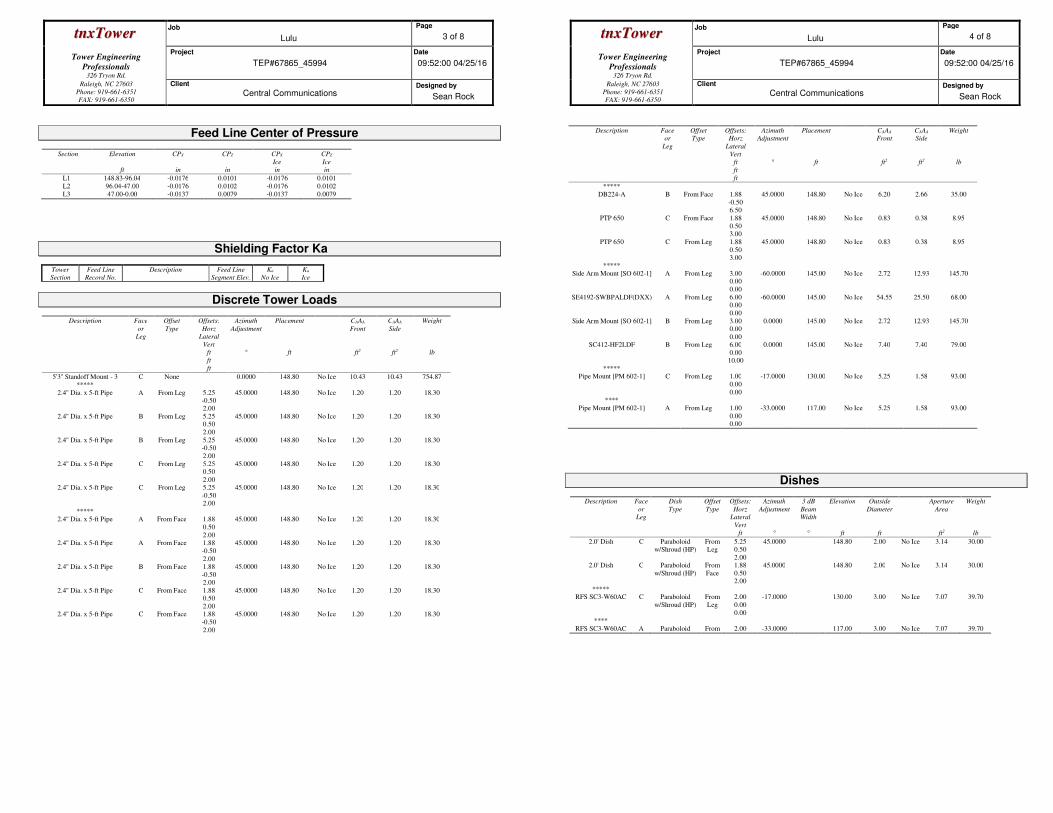
ttnnxxTToowweerr Job
Lulu
Page
3 of 8
Tower Engineering
Professionals
326 Tryon Rd.
Project
TEP#67865_45994
Date
09:52:00 04/25/16
Raleigh, NC 27603
Phone: 919-661-6351
FAX: 919-661-6350
Client
Central Communications Designed by
Sean Rock
Feed Line Center of Pressure
Section Elevation
ft
CPX
in
CPZ
in
CPX
Ice
in
CPZ
Ice
in
L1 148.83-96.04 -0.0176 0.0101 -0.0176 0.0101
L2 96.04-47.00 -0.0176 0.0102 -0.0176 0.0102
L3 47.00-0.00 -0.0137 0.0079 -0.0137 0.0079
Shielding Factor Ka
Tower
Section Feed Line
Record No. Description Feed Line
Segment Elev. Ka
No Ice Ka
Ice
Discrete Tower Loads
Description Face
or
Leg
Offset
Type
Offsets:
Horz
Lateral
Vert
ft
ft
ft
Azimuth
Adjustment
°
Placement
ft
CAAA
Front
ft2
CAAA
Side
ft2
Weight
lb
5'3'' Standoff Mount - 3 C None 0.0000 148.80 No Ice 10.43 10.43 754.87
*****
2.4'' Dia. x 5-ft Pipe A From Leg 5.25 -0.50 2.00
45.0000 148.80 No Ice 1.20 1.20 18.30
2.4'' Dia. x 5-ft Pipe B From Leg 5.25 0.50
2.00
45.0000 148.80 No Ice 1.20 1.20 18.30
2.4'' Dia. x 5-ft Pipe B From Leg 5.25 -0.50
2.00
45.0000 148.80 No Ice 1.20 1.20 18.30
2.4'' Dia. x 5-ft Pipe C From Leg 5.25 0.50
2.00
45.0000 148.80 No Ice 1.20 1.20 18.30
2.4'' Dia. x 5-ft Pipe C From Leg 5.25
-0.50 2.00
45.0000 148.80 No Ice 1.20 1.20 18.30
***** 2.4'' Dia. x 5-ft Pipe A From Face 1.88
0.50
2.00
45.0000 148.80 No Ice 1.20 1.20 18.30
2.4'' Dia. x 5-ft Pipe A From Face 1.88
-0.50
2.00
45.0000 148.80 No Ice 1.20 1.20 18.30
2.4'' Dia. x 5-ft Pipe B From Face 1.88
-0.50 2.00
45.0000 148.80 No Ice 1.20 1.20 18.30
2.4'' Dia. x 5-ft Pipe C From Face 1.88 0.50
2.00
45.0000 148.80 No Ice 1.20 1.20 18.30
2.4'' Dia. x 5-ft Pipe C From Face 1.88
-0.50
2.00
45.0000 148.80 No Ice 1.20 1.20 18.30
ttnnxxTToowweerr Job
Lulu
Page
4 of 8
Tower Engineering
Professionals
326 Tryon Rd.
Project
TEP#67865_45994
Date
09:52:00 04/25/16
Raleigh, NC 27603
Phone: 919-661-6351
FAX: 919-661-6350
Client
Central Communications Designed by
Sean Rock
Description Face
or
Leg
Offset
Type
Offsets:
Horz
Lateral
Vert
ft
ft
ft
Azimuth
Adjustment
°
Placement
ft
CAAA
Front
ft2
CAAA
Side
ft2
Weight
lb
*****
DB224-A B From Face 1.88
-0.50 6.50
45.0000 148.80 No Ice 6.20 2.66 35.00
PTP 650 C From Face 1.88
0.50 3.00
45.0000 148.80 No Ice 0.83 0.38 8.95
PTP 650 C From Leg 1.88
0.50 3.00
45.0000 148.80 No Ice 0.83 0.38 8.95
*****
Side Arm Mount [SO 602-1] A From Leg 3.00 0.00
0.00
-60.0000 145.00 No Ice 2.72 12.93 145.70
SE4192-SWBPALDF(DXX) A From Leg 6.00 0.00
0.00
-60.0000 145.00 No Ice 54.55 25.50 68.00
Side Arm Mount [SO 602-1] B From Leg 3.00 0.00
0.00
0.0000 145.00 No Ice 2.72 12.93 145.70
SC412-HF2LDF B From Leg 6.00
0.00 10.00
0.0000 145.00 No Ice 7.40 7.40 79.00
***** Pipe Mount [PM 602-1] C From Leg 1.00
0.00
0.00
-17.0000 130.00 No Ice 5.25 1.58 93.00
****
Pipe Mount [PM 602-1] A From Leg 1.00
0.00 0.00
-33.0000 117.00 No Ice 5.25 1.58 93.00
Dishes
Description Face
or
Leg
Dish
Type
Offset
Type
Offsets:
Horz
Lateral
Vert
ft
Azimuth
Adjustment
°
3 dB
Beam
Width
°
Elevation
ft
Outside
Diameter
ft
Aperture
Area
ft2
Weight
lb
2.0' Dish C Paraboloid w/Shroud (HP)
From Leg
5.25 0.50
2.00
45.0000 148.80 2.00 No Ice 3.14 30.00
2.0' Dish C Paraboloid
w/Shroud (HP)
From
Face
1.88
0.50 2.00
45.0000 148.80 2.00 No Ice 3.14 30.00
***** RFS SC3-W60AC C Paraboloid
w/Shroud (HP)
From
Leg
2.00
0.00
0.00
-17.0000 130.00 3.00 No Ice 7.07 39.70
****
RFS SC3-W60AC A Paraboloid From 2.00 -33.0000 117.00 3.00 No Ice 7.07 39.70
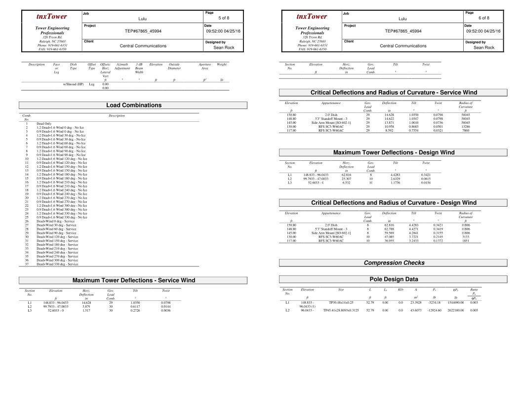
ttnnxxTToowweerr Job
Lulu
Page
5 of 8
Tower Engineering
Professionals
326 Tryon Rd.
Project
TEP#67865_45994
Date
09:52:00 04/25/16
Raleigh, NC 27603
Phone: 919-661-6351
FAX: 919-661-6350
Client
Central Communications Designed by
Sean Rock
Description Face
or
Leg
Dish
Type
Offset
Type
Offsets:
Horz
Lateral
Vert
ft
Azimuth
Adjustment
°
3 dB
Beam
Width
°
Elevation
ft
Outside
Diameter
ft
Aperture
Area
ft2
Weight
lb
w/Shroud (HP) Leg 0.00 0.00
Load Combinations
Comb.
No.
Description
1 Dead Only
2 1.2 Dead+1.6 Wind 0 deg - No Ice
3 0.9 Dead+1.6 Wind 0 deg - No Ice 4 1.2 Dead+1.6 Wind 30 deg - No Ice
5 0.9 Dead+1.6 Wind 30 deg - No Ice
6 1.2 Dead+1.6 Wind 60 deg - No Ice 7 0.9 Dead+1.6 Wind 60 deg - No Ice
8 1.2 Dead+1.6 Wind 90 deg - No Ice 9 0.9 Dead+1.6 Wind 90 deg - No Ice
10 1.2 Dead+1.6 Wind 120 deg - No Ice 11 0.9 Dead+1.6 Wind 120 deg - No Ice
12 1.2 Dead+1.6 Wind 150 deg - No Ice 13 0.9 Dead+1.6 Wind 150 deg - No Ice
14 1.2 Dead+1.6 Wind 180 deg - No Ice
15 0.9 Dead+1.6 Wind 180 deg - No Ice 16 1.2 Dead+1.6 Wind 210 deg - No Ice
17 0.9 Dead+1.6 Wind 210 deg - No Ice
18 1.2 Dead+1.6 Wind 240 deg - No Ice 19 0.9 Dead+1.6 Wind 240 deg - No Ice
20 1.2 Dead+1.6 Wind 270 deg - No Ice 21 0.9 Dead+1.6 Wind 270 deg - No Ice 22 1.2 Dead+1.6 Wind 300 deg - No Ice
23 0.9 Dead+1.6 Wind 300 deg - No Ice
24 1.2 Dead+1.6 Wind 330 deg - No Ice 25 0.9 Dead+1.6 Wind 330 deg - No Ice
26 Dead+Wind 0 deg - Service 27 Dead+Wind 30 deg - Service
28 Dead+Wind 60 deg - Service
29 Dead+Wind 90 deg - Service 30 Dead+Wind 120 deg - Service
31 Dead+Wind 150 deg - Service 32 Dead+Wind 180 deg - Service
33 Dead+Wind 210 deg - Service 34 Dead+Wind 240 deg - Service
35 Dead+Wind 270 deg - Service 36 Dead+Wind 300 deg - Service
37 Dead+Wind 330 deg - Service
Maximum Tower Deflections - Service Wind
Section
No.
Elevation
ft
Horz.
Deflection
in
Gov.
Load
Comb.
Tilt
°
Twist
°
L1 148.833 - 96.0433 14.628 29 1.0350 0.0798 L2 99.7933 - 47.0033 5.879 30 0.6117 0.0144
L3 52.6033 - 0 1.517 30 0.2726 0.0036
ttnnxxTToowweerr Job
Lulu
Page
6 of 8
Tower Engineering
Professionals
326 Tryon Rd.
Project
TEP#67865_45994
Date
09:52:00 04/25/16
Raleigh, NC 27603
Phone: 919-661-6351
FAX: 919-661-6350
Client
Central Communications Designed by
Sean Rock
Section
No.
Elevation
ft
Horz.
Deflection
in
Gov.
Load
Comb.
Tilt
°
Twist
°
Critical Deflections and Radius of Curvature - Service Wind
Elevation
ft
Appurtenance Gov.
Load
Comb.
Deflection
in
Tilt
°
Twist
°
Radius of
Curvature
ft
150.80 2.0' Dish 29 14.628 1.0350 0.0798 50045 148.80 5'3'' Standoff Mount - 3 29 14.622 1.0347 0.0798 50045
145.00 Side Arm Mount [SO 602-1] 29 13.871 1.0010 0.0736 50045
130.00 RFS SC3-W60AC 29 10.958 0.8683 0.0501 13286 117.00 RFS SC3-W60AC 29 8.592 0.7554 0.0321 7860
Maximum Tower Deflections - Design Wind
Section
No.
Elevation
ft
Horz.
Deflection
in
Gov.
Load
Comb.
Tilt
°
Twist
°
L1 148.833 - 96.0433 62.816 8 4.4283 0.3421
L2 99.7933 - 47.0033 25.307 10 2.6329 0.0615 L3 52.6033 - 0 6.532 10 1.1736 0.0154
Critical Deflections and Radius of Curvature - Design Wind
Elevation
ft
Appurtenance Gov.
Load
Comb.
Deflection
in
Tilt
°
Twist
°
Radius of
Curvature
ft
150.80 2.0' Dish 8 62.816 4.4283 0.3421 11806
148.80 5'3'' Standoff Mount - 3 8 62.788 4.4271 0.3419 11806
145.00 Side Arm Mount [SO 602-1] 8 59.569 4.2841 0.3155 11806 130.00 RFS SC3-W60AC 10 47.085 3.7221 0.2145 3133
117.00 RFS SC3-W60AC 10 36.955 3.2433 0.1372 1851
Compression Checks
Pole Design Data
Section
No.
Elevation
ft
Size
L
ft
Lu
ft
Kl/r
A
in2
Pu
lb
φPn
lb
Ratio
Pu
φPn
L1 148.833 -
96.0433 (1)
TP30.48x14x0.25 52.79 0.00 0.0 23.3928 -5234.18 1544690.00 0.003
L2 96.0433 - TP45.41x28.8093x0.3125 52.79 0.00 0.0 43.6073 -12924.60 2622100.00 0.005
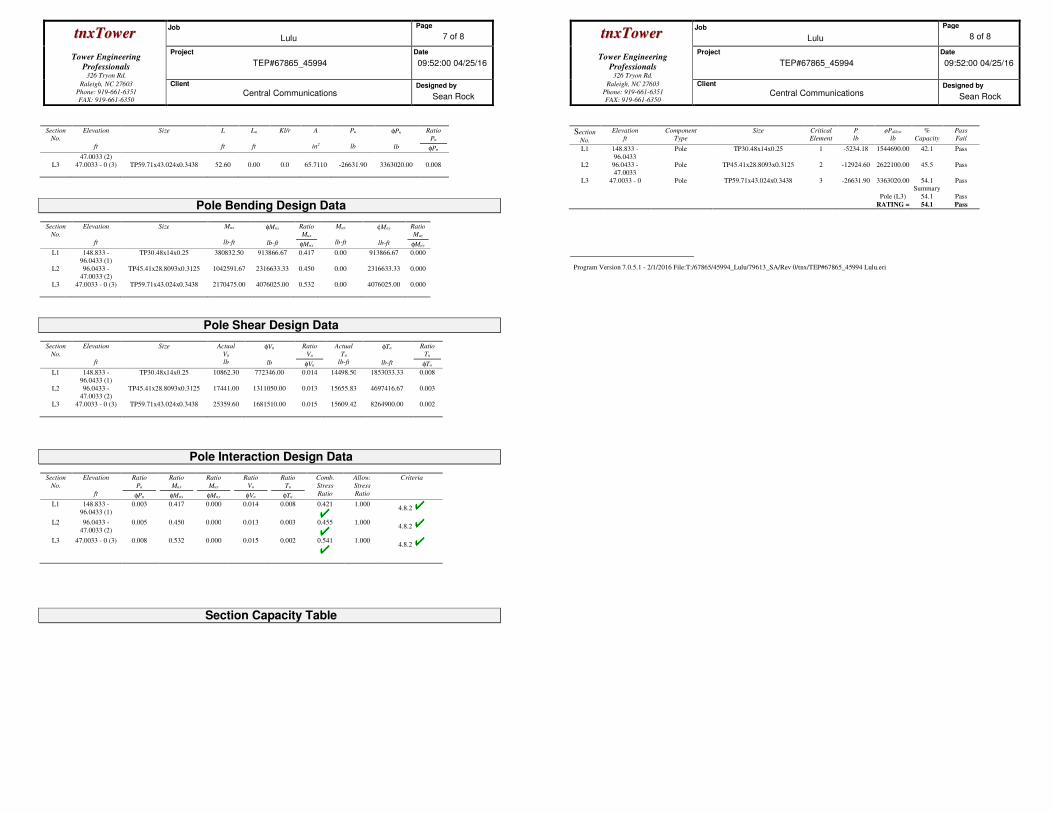
ttnnxxTToowweerr Job
Lulu
Page
7 of 8
Tower Engineering
Professionals
326 Tryon Rd.
Project
TEP#67865_45994
Date
09:52:00 04/25/16
Raleigh, NC 27603
Phone: 919-661-6351
FAX: 919-661-6350
Client
Central Communications Designed by
Sean Rock
Section
No.
Elevation
ft
Size
L
ft
Lu
ft
Kl/r
A
in2
Pu
lb
φPn
lb
Ratio
Pu
φPn
47.0033 (2)
L3 47.0033 - 0 (3) TP59.71x43.024x0.3438 52.60 0.00 0.0 65.7110 -26631.90 3363020.00 0.008
Pole Bending Design Data
Section
No.
Elevation
ft
Size
Mux
lb-ft
φMnx
lb-ft
Ratio
Mux
φMnx
Muy
lb-ft
φMny
lb-ft
Ratio
Muy
φMny
L1 148.833 -
96.0433 (1)
TP30.48x14x0.25 380832.50 913866.67 0.417 0.00 913866.67 0.000
L2 96.0433 - 47.0033 (2)
TP45.41x28.8093x0.3125 1042591.67 2316633.33 0.450 0.00 2316633.33 0.000
L3 47.0033 - 0 (3) TP59.71x43.024x0.3438 2170475.00 4076025.00 0.532 0.00 4076025.00 0.000
Pole Shear Design Data
Section
No.
Elevation
ft
Size
Actual
Vu
lb
φVn
lb
Ratio
Vu
φVn
Actual
Tu
lb-ft
φTn
lb-ft
Ratio
Tu
φTn
L1 148.833 -
96.0433 (1)
TP30.48x14x0.25 10862.30 772346.00 0.014 14498.50 1853033.33 0.008
L2 96.0433 - 47.0033 (2)
TP45.41x28.8093x0.3125 17441.00 1311050.00 0.013 15655.83 4697416.67 0.003
L3 47.0033 - 0 (3) TP59.71x43.024x0.3438 25359.60 1681510.00 0.015 15609.42 8264900.00 0.002
Pole Interaction Design Data
Section
No.
Elevation
ft
Ratio
Pu
φPn
Ratio
Mux
φMnx
Ratio
Muy
φMny
Ratio
Vu
φVn
Ratio
Tu
φTn
Comb.
Stress
Ratio
Allow.
Stress
Ratio
Criteria
L1 148.833 -
96.0433 (1)
0.003 0.417 0.000 0.014 0.008 0.421
1.000 4.8.2
L2 96.0433 -
47.0033 (2)
0.005 0.450 0.000 0.013 0.003 0.455
1.000 4.8.2
L3 47.0033 - 0 (3) 0.008 0.532 0.000 0.015 0.002 0.541
1.000 4.8.2
Section Capacity Table
ttnnxxTToowweerr Job
Lulu
Page
8 of 8
Tower Engineering
Professionals
326 Tryon Rd.
Project
TEP#67865_45994
Date
09:52:00 04/25/16
Raleigh, NC 27603
Phone: 919-661-6351
FAX: 919-661-6350
Client
Central Communications Designed by
Sean Rock
Section
No.
Elevation
ft
Component
Type
Size Critical
Element
P
lb
øPallow
lb
%
Capacity
Pass
Fail
L1 148.833 -
96.0433
Pole TP30.48x14x0.25 1 -5234.18 1544690.00 42.1 Pass
L2 96.0433 - 47.0033
Pole TP45.41x28.8093x0.3125 2 -12924.60 2622100.00 45.5 Pass
L3 47.0033 - 0 Pole TP59.71x43.024x0.3438 3 -26631.90 3363020.00 54.1 Pass Summary
Pole (L3) 54.1 Pass RATING = 54.1 Pass
Program Version 7.0.5.1 - 2/1/2016 File:T:/67865/45994_Lulu/79613_SA/Rev 0/tnx/TEP#67865_45994 Lulu.eri

April 25, 2016 149-ft Monopole Tower Structural Analysis Lulu TEP Project Number 67865_45994, Revision 0 Page 7
tnxTower Report - version 7.0.5.1
APPENDIX B
COAX CONFIGURATION