Embed Size (px)
Citation preview

Collection of Examples“Dust Explosion Protection
for Machines and Equipment”Part 1: Mills, crushers, mixers, separators, screeners
2013ISBN 978-92-843-2182-7ISSN 1015-8022
ISSA Prevention Series No. 2057 (E)
ISSAInternational Sectionon Prevention in theChemical IndustryKurfürsten Anlage 6269115 HeidelbergGermany
ISSAInternational Sectionon Machine andSystem SafetyDynamostraße 7-1168165 MannheimGermany

2
has 336 members (government authorities and public institutions) in 157 countries. The headquarters of the ISSA are at the International Labour Organization in Geneva. Its main goal is the promotion and improvement of SOCIAL SECURITY in all parts of the world.
To improve occupational safety and health in industrial plants, the
was established in 1975. It handles matters relating to the safety of machinery plants and systems.
Chair and secretariat:Berufsgenossenschaft Nahrungsmittel und Gastgewerbe (BGN),68165 Mannheim, Germany
To promote work safety in plants of the chemical industry, including plastics, explosives, mineral oil and rubber industries, the
was set up in 1970. Chair and secretariat:
Berufsgenossenschaft Rohstoffe und chemische Industrie (BG RCI),69115 Heidelberg, Germany
ISSA INTERNATIONAL SECTION ON
MACHINE AND SYSTEM SAFETY
ISSA INTERNATIONAL SECTION
ON PREVENTION IN THE
CHEMICAL INDUSTRY

3
Collection of Examplesfor the Brochure
“Dust Explosion Protection for Machines and Equipment”
Part 1:Mills, crushers, mixers, separators, screeners
Compendium for Practical Use
Published by
ISSA International Section on Machine and System Safety
Dynamostrasse 7-1168165 Mannheim
Germany
ISSA International Section on Preventionin the Chemical Industry
Kurfürsten Anlage 6269115 Heidelberg
Germany

4
Preface
The ISSA (International Social Security Association) by its Special Com-mission on Prevention and with its professional oriented sections, has defined a target to analyse work-related risks. Through exchange of in-formation, publications and conferences these risks should be identified and suggestions should be made for minimizing such risks.
The Section Machine and System Safety and the Chemistry Section foun-ded a common “Working Group Explosion Protection“, in order to promote international exchange of experience between experts and to elaborate common solutions for specific problems. In this way we want to contribute to a high and common state-of-the-art safety in industrialized countries. We are willing to share our knowledge with industrially less developed countries.
This compendium should enable project engineers, managers, safety professionals and other interested parties to judge if explosion risks are present in their own company or during the construction, equipment and installation, even without specific knowledge on explosion protection. The compendium is not intended to answer the question whether protective measures are necessary and possible: due to differences in national regu-lations in many situations it is not possible to make definitive statements. Instead problems are highlighted and solutions are formulated, in order to meet safety objectives.
............................. .........................
Chairman of the board Chairman of the board of the Section on of the Section on Prevention Machine and System Safety in the Chemical Industry (Ass. N. Weis) (Dr. E. Radek)

5
Working Group Explosion Protection
Authors of this brochure
Chairman of the project group “Collection of Examples”
Dr Frank Hauert, Berufsgenossenschaft Nahrungsmittel und Gastgewerbe, Mannheim
The brochure has been prepared under the direction of Dr Hauert. He has had a significant input on structure and content. He died because of a tragic accident before the brochure was completed. We owe him our special gratitude. The members of this project group therefore devote this publication to him.
Authors
Dr A. Arnold, BGN, Mannheim ............................................................................................ (D)Dr M. Glor, Swiss Process Safety Consulting GmbH, Allschwil .......................................... (CH)A. Harmanny, ISMA, Kontich ................................................................................................ (B) Dr Frank Hauert, BGN .......................................................................................................... (D) N. Jaeger, Syngenta, Basel ................................................................................................. (CH)Dr Z. Kramar, SlQ, Ljubljana ................................................................................................ (Sl)G. van Laar, Inburex Consulting GmbH, Hamm-Breda ..................................................... (D/NL)G. Nied, AZO GmbH & CO KG, Osterburken ........................................................................ (D)Dr R. J. Ott, ESCIS, Meggen ................................................................................................ (CH)Prof. Dr S. Radandt, FSA, Mannheim ................................................................................... (D)R. Siwek, FireEx Consultant GmbH, Kaiseraugst ................................................................ (CH)
Design and graphics
Dr Frank Hauert, Mannheim .................................................................................................. (D)Dr Roland J. Ott, Meggen ..................................................................................................... (CH)Dipl.-Designer Dieter Settele, Mannheim ............................................................................. (D)
Other members of the working group
M. Bloch, INRS, Paris ........................................................................................................... (F)Ch. Bosshard, Suva, Luzern ............................................................................................... (CH)Dr B. Dyrba, BG RCI,Heidelberg .......................................................................................... (D)Prof. Dr A. Fiumara, Milano .................................................................................................... (I)Dr M. Gschwind (Chairman), Suva, Luzern ......................................................................... (CH)K. Kopia, AUVA, Wien ........................................................................................................... (A)Dr O. Losert, BG RCI, Heidelberg ......................................................................................... (D)Dr G. Pellmont, Pellmont Explosionsschutz, Binningen/Basel ............................................. (CH)F. Pera, INAIL, Roma ............................................................................................................ (I)B. Poga, BG RCI, Heidelberg ............................................................................................... (D)B. Sallé, INRS, Paris ............................................................................................................. (F)Dr M. Scheid, BAM, Berlin .................................................................................................... (D)Dr K-W. Stahmer, IFA, Sankt Augustin ................................................................................. (D)M. von Arx, Suva, Luzern ..................................................................................................... (CH)W. Witvoet, SABIC EuroPetroChemicals, Geleen ............................................................... (NL)

6
Contents
Preface ...................................................................................... 4
Introductory Remarks ............................................................. 7
Introduction ............................................................................ 10
1 Grinders ............................................................................... 111.1 High speed mills ..........................................................................................11
1.1.1 Examples of plants with constructional measures .............................15
1.1.1.1 Explosion resistant construction ...........................................15 1.1.1.2 Explosion venting .................................................................17 1.1.1.3 Explosion suppression ........................................................19
1.1.2 Example of plant protected by inerting .............................................21
1.2 Jet mills .......................................................................................................221.3 Tumbling mills .............................................................................................23 1.4 Roll mills ......................................................................................................24
2 Crushers .............................................................................. 27
3 Mixers .................................................................................. 27 3.1 Mixers without moving internal elements ...................................................27
3.2 Mixers with moving internal elements .........................................................29
4 Separators ........................................................................... 33 4.1 Centrifugal separators (cyclones) ................................................................33
4.2 Gravity separators .......................................................................................34
4.3 Wind sifters ..................................................................................................35
4.4 Filter separators .........................................................................................36
4.5 Electrical precipitators .................................................................................37
4.6 Scrubbers ....................................................................................................37
5 Screeners/Sifters ................................................................ 38 5.1 Screeners/Sifters without moving internal elements ...................................38
5.2 Screeners/Sifters with moving internal elements ........................................39
ISSA Publications (Explosion protection) .......................... 41

7
Introductory Remarks The theme “Explosion safety” of machinery is e.g. in the European Community dealt with in two directives: the Machinery Directive (2006/42/EC) and the ATEX Explo-sion Directive (94/9/EC). Both directives lay down Essential Safety Rules (ESR). A fundamental requirement in both directives is to perform risk assessments. Such assessments are the fundamentals for the application of machinery in companies. This application is laid down in another Directive, the ATEX 137 directive (199/92/EC). Here too a risk assessment is required.
This compendium is intended to facilitate those responsibles in companies to estimate the explosion risks during selection and operation of installations and machinery (included in this brochure) in explosion hazardous area and to take protective measures based on the risk assessment.
In the next chapters typical dust explosion hazards and possible protective measures will be discussed for various machinery and installations.
As described in various ISSA brochures, especially “Dust Explosion Prevention and Protection for Machines and Equipment - Basic Principles” (ISSA, 2004, Mannheim, ISBN 92-843-7129-5), both preventive and protective measures can be applied, as single measures or in combination.
Preventive Measures
• Avoidance of explosive atmospheres by e.g.
•• limitation of the concentration
•• inerting
•• use of vacuum
• Avoidance of effective ignition sources

8
If “avoidance of effective ignition sources” is applied as the only preventive measure, it should be guaranteed that all relevant effective ignition sources are reliably pre-vented. Meeting this requirement will become increasingly difficult with decreasing minimum ignition energy and increasing complexity of installations and processes. When products with a minimum ignition energy below 10 mJ are processed, in practice it will be hard to apply “avoidance of effective ignition sources” as the only preventive measure. In addition it needs to be taken into account that the minimum ignition energy decreases with increasing temperature. Additional preventive mea-sures “avoidance of explosive atmospheres” or protective measures then have to be applied. For products with a low minimum ignition energy phlegmatisation (partial inerting) could be used as additional measure. Due to the reduction in oxygen con-centration the ignition sensitivity of the product is reduced.
����������
� ���������� ������������
�� ������ ���������������� �
� �����
���������
������ ���������� ������������
������ ��
��������������� ����������
���� �� ��� ����� �!��������� �
�� ������ ������� �� ��������� ����������
��������
������������� �������
��������� ����
"� �������������� ��������
��
��
���
���
���
������#�������� ���������������#�������� �������������
��
Fig. 1: Scheme to estimate protective measures as a function of the minimum ignition energy (MIE) of the product involved. In general the MIE is at first tested with an electrical discharge spark somewhat expanded in time (with inductance in the discharge circuitry). If the resulting MIE1mH is found to be below 10 mJ, the test is repeated without inductance in the discharge circuitry (MIE0mH).

9
Constructional Measures
• explosion-resistant design for the expected explosion pressure combined with explosion isolation
• explosion-resistant design with explosion venting combined with explosion isola-tion
• explosion-resistant design with explosion suppression combined with explosion isolation
The adequate choice of measures depends on the details of plant construction and layout, and on the properties of the involved dust or powder. Usually an individual assessment must be made, taking the advantages and disadvantages of the various safety measures, as well as their limits of application, into consideration. Therefore, the explosion risks have to be determined and assessed (for example according the European guideline 1999/92/EC) and appropriate measures have to be applied.
Although the collection of examples in this document indicates a number of possible explosion hazards and protective measures, it is not exhaustive. The illustrations show some typical solutions that have proved effective. For each application, however, the specific boundary conditions need to be taken into account (for example pressure piling in interconnected vessels, forbidding of venting because of toxic materials, exceeding maximum rates of pressure rise when using explosion suppression).
Furthermore, instable chemical products, or products that are sensitive to ignition by impact and hybrid mixtures, need special safety considerations, appropriate to each case.
The equipment and machines that are described hereafter technically have to be in conformity with the current technical state of the art. Especially protective systems such as rotary valves or explosion isolation valves have to be approved for prior to use, e.g. have to be certified in the EC by notified testing institutes. Regular inspection and maintenance is required, in order to prevent risks due to mechanical failures.
The definitions of zones can be found in the ISSA document “Practical Assistance for the Preparation of an Explosion Protection Document” (ISSA, 2006, Mannheim, ISBN 92-843-1167-5) or in the European directive 1999/92/EC.
This collection of examples is the first part of a revision of the Collection of Examples for the booklet “Dust explosion protection for machines and equipment” that was published in 1990 by the ISSA section “Machine Sa-fety” and in particular is aiming to the end-users of equipment and plants.

10
Introduction
In these examples it will be indicated which of the 13 potential ignition sources [EN 1127-1] are relevant for the machines. Which ignition sources may arise and how can these be prevented.
The potential ignition sources include:
1. Hot surfaces, 2. Flames and hot gases (including hot particles),
3. Mechanically generated sparks, 4. Electrical apperatus (electrical equipment sources), 5. Stray electric currents, cathodic corrosion protection,
6. Static electricity, 7. Lightning,
8. Radio frequency (RF): electromagnetic waves from
104 Hz to 3 • 1012 Hz (high frequency),
9. Electromagnetic waves from
3 • 1011 Hz to 3 • 1015 Hz,
10. Ionizing radiation,
11. Ultrasonics,
12. Adiabatic compression and shock waves,
13. Exothermic reactions, including self-ignition of dusts
From experience it is known that the ignition sources indicated in bold are especially relevant.
Each ignition source has to be assessed separately to verify if it is effective, in order to determine if effective ignition sources can be excluded during normal operation and during rare fault conditions.
For some situations protective measures that have proven to be effective will be presented. Typical examples will be given. However, it has to be noted that every plant will differ and therefore measures need to be adapted to the specific situation.

11
1 Grinders
Grinders and similar size-reducing equipment should generally be regarded as pos-sible ignition sources since mechanical sparks or hot surfaces can be generated in them by product blockage, the high-speed grinding elements themselves or the introduction of tramp material.
Whether or not these can be seen as effective ignition sources will depend in each case on a number of factors including the circumferential speed of the grinding ele-ments, the minimum ignition energy and ignition temperature of the material being ground.
Explosions which arise inside grinders are rather rare. However, often ignition sour-ces are created there, which might cause an ignition of explosive atmospheres in down stream located equipment. Therefore, in case of explosion hazards appropriate measures (such as inerting, constructional measures) should not be limited to the grinders alone, but also be applied to all interconnected equipment. Measures to prevent explosion propagation need to be included as well. Ignition sources which might arise in other parts of the installation are not included in following examples.
In the next example (high speed mills) the three basic protective measures and inerting will be presented. For other kinds of grinders (chapt. 1.2 – 1.4) some pro-tective measures might not be required, based on the analysis of potential ignition sources.
1.1 High-speed mills
High-speed mills such as pinned disk mills, beater mills, cutter mills and hammer mills must invariably be regarded as potential ignition sources.
Potential ignition sources could, for example arise due to:
• intrusion of tramp material into mills
• loosening of parts inside the mill
• contact of moving parts with mill housing or screen
• overheating of bearings
• overheating of ground material due to friction
Avoidance of effective ignition sources is a measure that can be used only in special cases (e.g. when the dust to be processed has an extremely high minimum ignition energy and ignition temperature).
Internal zone classification: The intended use of mills is operation at full capacity. In such conditions the product concentration is very high and an explosion is not possible. During start-up or shut-down explosive atmospheres may arise occasionally and therefore at least a zone 21 is present. If the intended use is not full capacity, or there is a frequent start/stop a zone 20 should be defined.

12
Fig. 2:
Schematic presentation of hammer mill.
Fig. 3:
Schematic presentation of a pinned disk mill. The loca-tions where ignition sources may arise have been indi-cated and are explained in table 1. [Picture: Hosokawa Alpine®]

13
Case
(a)
(b)
(c)
(d)
(e)
Creation of ignition source
Intrusion of tramp material, such as metal, stone, smoul-dering lumps…
Loosening or failure of pins
Out of balance of rotor, causing friction
Overheating of bearings
Overheating of ground material due to friction of rotor against deposits
Ignition source according EN 1127-1
hot surfaces, flames and hot gases, mechanically generated sparks
hot surfaces, mechanically generated sparks
hot surfaces
hot surfaces
Self-ignition
Possible preventive measures
Upstream installation of sifters, heavy-material separators, detection of smouldering lumps
Servicing (regular inspection, maintenance, repair; application of correct spares)
Servicing, vibration control
Temperature control
Regular cleaning, temperature control, cold milling
Fig. 4:
Schematic section of a cutter mill. The pos-sible production or release of fines during the cutting process determines if there is an explosion hazard.
Table 1: Detailed ignition source analysis of the pinned disk mill from fig. 3.
produkt in
rotor
outlet screen

14
Fig. 5: Schematic presentation of a beater mill: product is ground between fixed mounted baffle plates and beater bars mounted on the moving rotor.
Preventive measures based upon “avoidance of effective ignition sources“ may re-duce explosion risks, but are in most situations insufficient to eliminate explosions completely. Therefore additional measures such as constructional measures or inerting are required.

15
1.1.1 Examples of plants with constructional measures1.1.1.1 Explosion resistant construction
In the next example, prevention of the various ignition sources, as identified in table 1, turned out to be insufficient. Therefore additionally the constructional measure “explosion resistant construction in combination with explosion isolation” has been applied.
Fig. 6: Example of a plant with a high-speed mill. The plant in this example has been designed explosion resistant for the maximum explosion pressure in combination with explosion isolation measures. For short distances (here < 6 m) between filter separator and mill no additional explosion isolation is required. [Picture: Hosokawa Alpine®]
A Entrance of combustible coarse product B Outlet/bagging of ground product
1 Screw conveyor 2 Heavy-material separator, metal separator 3 Air inlet 4 Explosion isolation valve 5 Rotary valve
6 Pinned disk mill 7 Filter separator 8 Air flow regulating valve 9 Fan 10 Air outlet
1
A
3
Fe
4
2
5
6
B
7
5
48 9
10

16
Protection:
Preventive measures
• Heavy-material separator (2) to prevent ignition sources (mechanically generated sparks, hot surfaces)
• Because the fan (9) poses no ignition sources according EN 14986, control of leaking filter elements by dust monitoring or a safety filter in front of the fan (9) is not necessary.
Constructional measures
• Range mill (6) - filter separator (7) - ducting between (6) and (7): explosion resis-tant design for the maximum explosion pressure
• Explosion isolation of the mill (6): product inlet (A) with certified rotary valve (5) (explosion resistant, flame proof) and air inlet (3) with certified explosion isolation valve (4)
• Explosion isolation of filter separator (7): product outlet (B) with certified rotary valve (5) (explosion resistant, flame proof) and air outlet (10) with certified explo-sion isolation valve (4)
• Rotary valves (5) are stopped in case of an explosion by detection system (de-pending on process and installation)
• All ducting between isolation systems is explosion resistant for the maximum ex-plosion pressure.
17
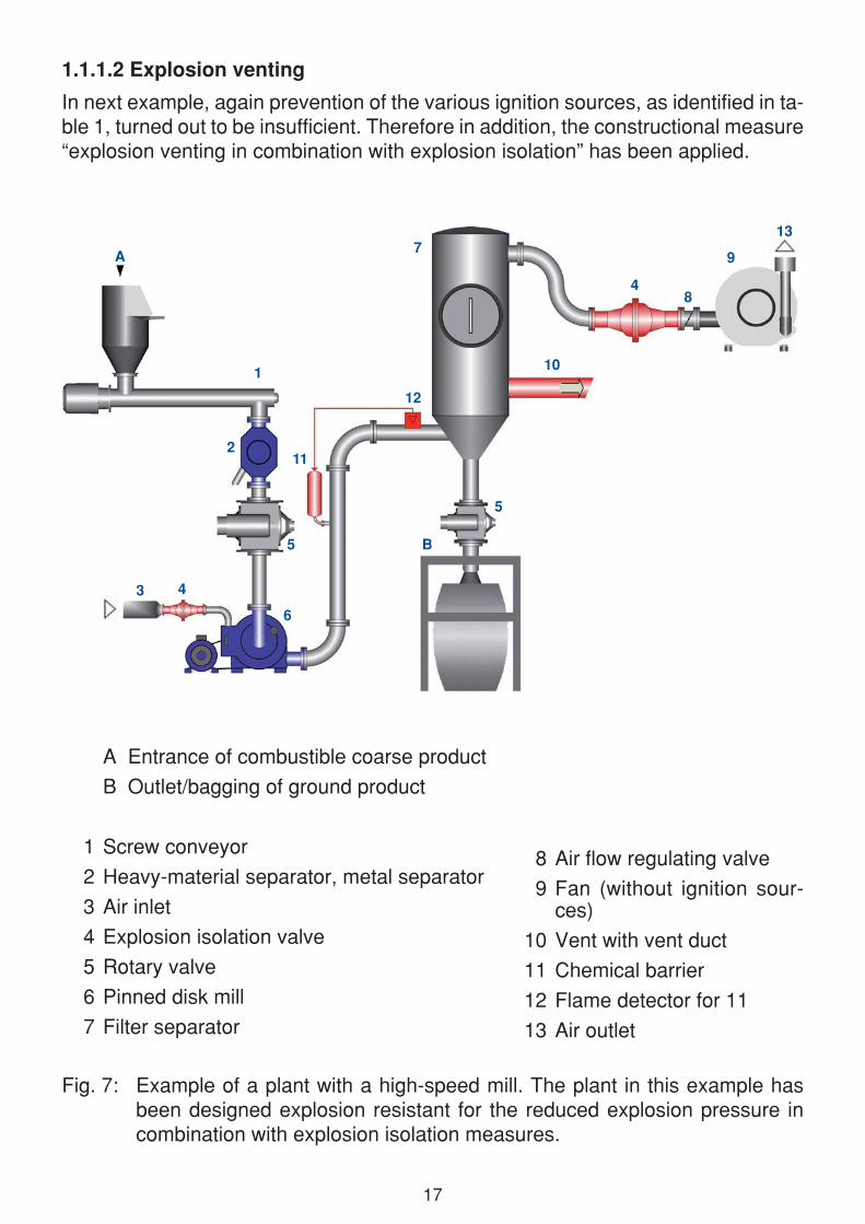
Fig. 7: Example of a plant with a high-speed mill. The plant in this example has been designed explosion resistant for the reduced explosion pressure in combination with explosion isolation measures.
A Entrance of combustible coarse product
B Outlet/bagging of ground product
1 Screw conveyor
2 Heavy-material separator, metal separator
3 Air inlet
4 Explosion isolation valve
5 Rotary valve
6 Pinned disk mill
7 Filter separator
8 Air flow regulating valve
9 Fan (without ignition sour-ces)
10 Vent with vent duct
11 Chemical barrier
12 Flame detector for 11
13 Air outlet
1.1.1.2 Explosion venting
In next example, again prevention of the various ignition sources, as identified in ta-ble 1, turned out to be insufficient. Therefore in addition, the constructional measure “explosion venting in combination with explosion isolation” has been applied.
1
A
3
4
2
5
6
B
7
4
8
9
10
11
12
5
13

18
Protection
Preventive measures
• Heavy-material separator (2) to prevent ignition sources (mechanically generated sparks, hot surfaces)
• Because the fan (9) poses no ignition sources according EN 14986, control of leaking filter elements by dust monitoring or a safety filter in front of the fan (9) is not necessary.
Constructional measures
• Filter (7) with explosion venting (10) (conforming EN 14491 and EN 14797)
• If a vent duct is required, the reduced explosion pressure will increase, which needs to be taken into account. Also recoil forces need to be taken into account. Venting to outside, into a safe area
• Mill (6), filter (7) and interconnecting ducting: explosion resistant design for the explosion pressure to be expected (according EN 14460)
• Explosion isolation of the product lines with certified rotary valves (5) (explosion resistant, flame proof) and a certified chemical barrier (11)
• Explosion isolation of air in- and outlet (3 and 13) with certified explosion isolation valve (4)
• Rotary valves (5) are stopped in case of an explosion by detection system (de-pending on process and installation).

19
1.1.1.3 Explosion suppression
In the third example the required safety level, due to insufficient prevention of the various ignition sources, as identified in table 1, has been obtained by an explosion suppression system.
Fig. 8: Example of a plant with a high-speed mill. The plant in this example has been protected with an explosion suppression system.
A Entrance of combustible coarse product
B Outlet/bagging of ground product
1 Screw conveyor
2 Heavy-material separator, metal separator
3 Air inlet
4 Explosion isolation valve
5 Rotary valve
6 Pinned disk mill
7 Filter separator
8 Air flow regulating valve
9 Fan
10 Explosion suppression
11 Chemical barrier
12 Flame detector for 11
13 Pressure detector for 10 (only one detector indica-ted)
14 Safety filter
15 Air outlet
1
A
3
2
5
6
B
7
5
4
8
15
10 10
13
11
12
14
9

20
Protection
Preventive measures
• Heavy-material separator (2) to prevent ignition sources (mechanically generated sparks, hot surfaces)
• Control of leaking filter elements by safety filter (14), because the subsequent fan is not free from ignition sources according EN 14986.
Constructional measures
• Explosion suppression (10) of the filter (7) (conforming EN 14373)
• Mill (6): explosion resistant design for the maximum explosion pressure (according EN 14460)
• Explosion isolation of the product lines with certified rotary valves (5) (explosion resistant, flame proof) and a certified chemical barrier (11)
• Explosion isolation of air inlet (3) with certified explosion isolation valve (4)
• Automatic shut down of the plant in case of an explosion
• All equipment at the clean air side should have the same resistance as the pro-tected system.

21
1.1.2 Example of plant protected by inerting
In this example the whole plant has been inerted, in order to prevent ignition of ex-plosive atmospheres.
A Entrance of combustible coarse product
B Outlet/bagging of ground product
1 Screw conveyor
2 Heavy-material separator, metal separator to protect the installation
3 Inert gas supply
4 Buffer vessel
5 Rotary valve
6 Pinned disk mill
Fig. 9: Example of an inerted plant with a high-speed mill.
7 Filter separator
8 Air flow regulating valve
9 Fan
10 Safety filter to prevent dust in inert gas recirculation
11 Oxygen monitoring
1
A
3
42
5
6
B
11
5
8
9
10
7

22
Protection:
Preventive measures
• Inerting with nitrogen (3), with control. Especially the oxygen concentration (11) needs to be controlled (with fault shut down of the whole plant) (Reference to CEN/TR 15281; 2006 Guidance on Inerting for the Prevention of Explosions)
The rotary valves (5) in fig. 9 are not intended as explosion isolation and therefore are not required to be explosion resistant and flame proof.
Internal zone classification
Because of the inerting no zone has to be defined inside the installation.
1.2 Jet mills
In jet mills the product to be ground is injected into the milling chamber together with pressurized air or inert gas through several nozzles. In this way a flow field is created causing highly energetic impact of product particles with other particles and the wall of the milling chamber.
Fig. 10: Schematic presentation of a jet mill.

23
Jet mills do not have internal moving parts. Hence there will be no mechanical ignition sources. Electrostatical ignition sources need to be considered. Only when internal coatings are present which are (electrostatically) non-conductive, propagating brush discharges have to be taken into account. If there are no such coatings and if the entrance of any ignition source can be prevented no further protective measures are required.
Jet mills also containing fast moving parts (such as screeners in classifier mills) should be treated as high-speed mills (section 1.1)
Internal zone classification:
Inside jet mills almost continuous there is a large amount of fines. During operation at full capacity the dust concentration often is very high and an explosion is not pos-sible. Depending on the way of operation (for example low product load, or frequent start/stop) a zone 20 should be defined. During start-up or shut-down explosive atmospheres may arise occasionally and therefore at least a zone 21 is present.
1.3 Tumbling mills
Tumbling mills are rotating drums, which contain a number of free moving grinding bodies. Tumbling mills can be subdivided into drum mills and tube mills (= elongated drum). In drum mills balls are applied as grinding bodies, whereas in tube mills rods are applied.
Fig. 11:
Schematic presentation of a tumbling mill. Grinding bodies might be balls or rods.

24
In tumbling mills friction can cause a substantial heating effect. In mills of 2-3 m dia-meter, for example, the temperature can rise from 20 °C to 100 °C within 2 hours.
Depending on the properties of the product, lumps of smouldering material can form after a certain residence time in the mill if deposits of the product are thick enough. Such smouldering lumps can act as an ignition source for dust explosions.
If smouldering material can not be excluded, experience has shown that inerting is a suitable preventive measure and explosion-resistant construction - in combination with explosion isolation - is a possible constructional protective measure.
If products are involved that are sensitive to ignition by impact, protective measures are always required.
Internal zone classification
Inside tumbling mills the dust concentration often exceeds the lower explosion limit (LEL) during operation. Therefore this type of mill usually is considered at least as a zone 21. Depending on the way of operation (for example high product load, or high speed) a zone 20 has to be defined.
1.4 Roll mills
In roll mills the product to be ground is crushed in between two rolls, which rotate in opposite directions.
1 Distributor
2 Feed regulator
3 Pre-crusher
4 Vibrating screen
5 Hull crusher
6 Eccentric drive
7 Hulls with sticking semolina
8 Pre-crushed material
9 Flour
Fig. 12:
Schematic presentation of a roll mill for grain with four rolls.

25
Roll mills do not generally constitute an ignition hazard if the separation of tramp material is carried out properly and also no hazardous heat development of the pro-duct due to friction will arise.
The possibilities available for suitable tramp material separation depend on the ap-plication and include:
• heavy-material separator,
• metal separator,
• magnetic separator,
• screens,
• stone sorters,
• graters
or combinations of these separating techniques.
Examples of possible measures against heat development are for example:
• monitoring of the roller speed
• monitoring of the performance of the drive assemblies
• monitoring of the cooling water temperature to avoid inadmissible temperature of the roller surfaces.
If the ignition sources mentioned cannot be avoided with sufficient certainty, suitable preventive or constructional measures are necessary, see section 1.1.
Internal zone classification:
Inside roll mills there is a continuous dense product flow. The appropriate zone de-pends on the particle size. With a large fraction of fines the concentration often is very high and an explosion is not possible. During start-up or shut-down explosive atmospheres may arise and therefore at least a zone 21 is present.
A variation on the roll mill is the roller mill which is used for coal crushing. In roller mills the coal is crushed between the rotating rollers and the grinding table. Since some coals do smoulder easily, the operation of such mills makes it very hard to avoid smouldering lumps as effective ignition sources.
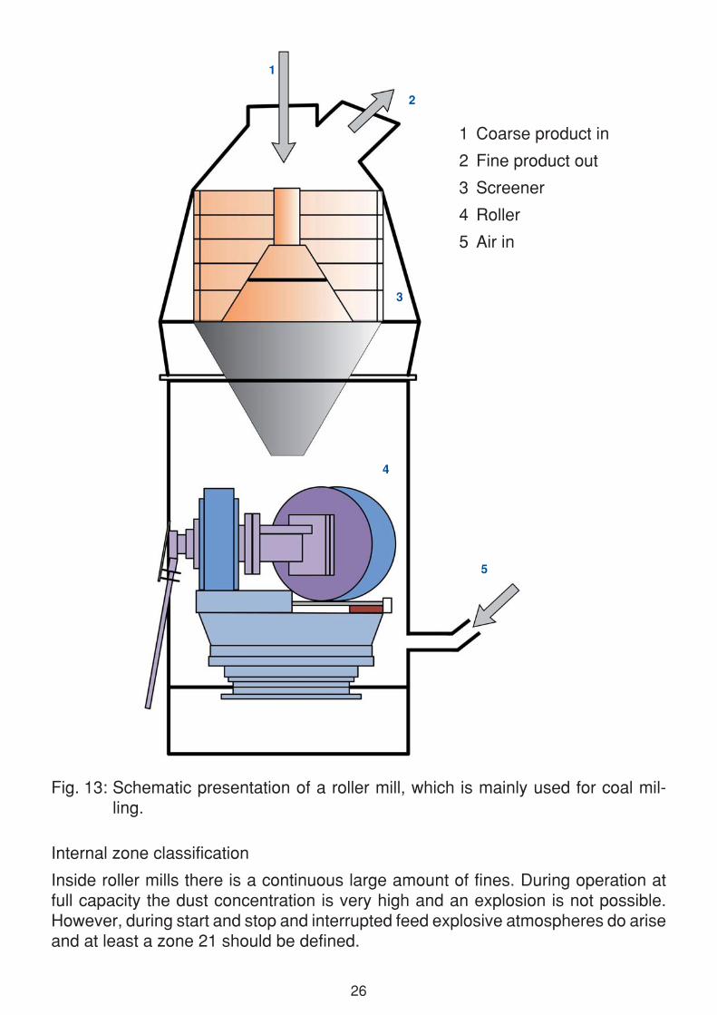
26
Internal zone classification
Inside roller mills there is a continuous large amount of fines. During operation at full capacity the dust concentration is very high and an explosion is not possible. However, during start and stop and interrupted feed explosive atmospheres do arise and at least a zone 21 should be defined.
Fig. 13: Schematic presentation of a roller mill, which is mainly used for coal mil-ling.
1 Coarse product in
2 Fine product out
3 Screener
4 Roller
5 Air in
1
3
2
5
4

27
2 Crushers
Low-speed crushers (safety crushers) are used for coarse crushing and for the re-tention of metallic constituents or other relatively large tramp material. Their circum-ferential speed is about 1 m · s-1. Experience to date shows that such type of safety crushers are not expected to create effective ignition sources.
Internal zone classification
Low-speed crushers, depending on the crushed product, typically have to be con-sidered as a zone 22.
High-speed crushers should be treated like high-speed mills when - due to the re-sulting fine dust - an explosion hazard is present.
3 Mixers
Operation techniques commonly employed in mixers - for example by mixer design or a high degree of filling - limit the formation of hazardous, explosive dust/air mix-tures. In such situations mixers can be operated with a sufficient degree of safety if reliable measures have been taken to avoid effective ignition sources. If the avoidance of effective ignition sources is not possible, however, additional measures such as inerting or constructional explosion protection must be employed.
Bearings extending into the mixing pan have to be protected against undue heating. With heated mixers the temperatures have to be limited such that no hazardous reactions (ignition of dust deposits or suspensions, spontaneous heating or decom-position processes) can occur.
3.1 Mixers without moving internal elements
With these mixers product mixing is obtained due to the movement of the mixing vessel or by airflow through the mixer
Mixers without moving internal elements include helical, drum, double cone, tumbler, container and air mixers.
Since there are no internal moving parts, ignition sources likely to be caused by such parts (e.g. sparks or hot surfaces) can be ignored.
However, when avoidance of effective ignition sources is the main base of protection, it is important to ensure that no ignition sources, e.g. lumps of smouldering material, or tramp material that may result into ignition sources are introduced.

28
Fig. 14: Example of a container mixer. [Picture: AZO® GmbH + Co. KG]
.
Fig. 15:
Example of an air mixer.
[Picture: Prof. Dr-Ing. Drs h.c. Manfred H. Pahl, University of Paderborn]

29
Potentially hazardous electrostatic discharges have to be avoided by taking appro-priate measures (Static Electricity - Ignition hazards and protective measures, ISSA, Heidelberg, 1996, ISBN 92-843-1099-7).
3.2 Mixers with moving internal elements
With these mixers, mixing is obtained by moving mixing elements. Examples are ploughshare, paddle, cone and ribbon mixers.
Fig. 16: Examples of mixing elements (top) and disagglomerating elements (down).
[Picture: Prof. Dr-Ing. Drs H.c. Manfred H. Pahl, University of Paderborn]

30
mechanically created fluidised bedFig. 17:
Schematic operation of a ploughshare mixer.
[Picture: Lödige® Industries GmbH]
chopper
Horizontal Lödige ploughshare mixer®:hurling and whirling principle
ploughshare®
mixing element
Fig. 18:
Schematic presentation of a heated cone mixer (Nauta mixer).
[Picture: Hosokawa Micron®]

31
In contrast to the mixers discussed in section 3.1, here internal moving parts are present and ignition hazards due to mechanically generated sparks and hot surfaces during fault conditions must be considered. When the mixer contains slow internal moving parts (v 1 m · s-1) and has low power requirements (W 4 kW), experience has shown that no additional ignition hazards are introduced by these parts.
In general effective ignition sources in mixers are not to be expected under condition that:
• during the charging or discharging processes, the mixer is stopped or operated at reduced speed (v 1 m · s-1). The reduced speed shall be guaranteed by technical measures,
Fig. 19:
Schematic presentation of a horizontal mixer (top). View into an opened hori-zontal mixer (left).
[Picture: Prof. Dr-Ing. Drs h.c. Manfred H. Pahl, University of Paderborn]

32
• no choppers or disintegrators are used during charging/discharging,
• any internal insulating coating of the mixer should have a breakdown voltage below 4 kV,
• internal bearings must be monitored,
• tramp material is avoided,
• sticky deposits, which have a tendency to self-ignition are prevented.
If a reliable prevention of ignition sources is not possible, additional measures are required.
Internal zone classification
The dust concentration inside a mixer depends very much on the particle size dis-tribution of the products, the mixing speed and the filling degree. In most situations, depending on the indicated parameters, the dust concentrations are either very high or very low and an explosion is not possible. However, during start and stop explo-sive atmospheres may arise and at least a zone 21 should be defined. However, depending on the mode of operation explosive atmospheres may become more likely (zone 20).

33
4 Separators
Separators are used to separate solids from air. Separators are applied with high product loads, e.g. at the end of a pneumatic conveying line, or with low product loads, such as fine dusts in aspiration systems.
Explosive atmospheres do not arise in all separators. Also the probability of effec-tive ignition sources depends very much on the kind of separator and the product involved.
In general inside separators effective ignition sources do not arise during normal operation on condition that:
• only conductive materials are applied and all conductive parts are reliable and permanent grounded (RE < 106 ),
• no insulating coating with a breakdown voltage beyond 4 kV is applied at loca-tions where there is impact of product (such processes generate high electrostatic charges and may cause powerful propagating brush discharges),
• for products with low melting points or when during separation at elevated tempe-ratures no product layers can be created (due to sintering or melting processes) with a breakdown voltage beyond 4 kV at locations where there is impact of pro-duct (such processes generate high electrostatic charges and may cause powerful propagating brush discharges),
• no self-ignition processes are initiated for example due to dust deposits and ele-vated temperatures,
• no effective ignition sources are introduced in the separator (e.g. lumps of smoul-dering material; explosion propagation through interconnected plant units),
• hot surfaces and mechanically generated sparks are prevented by using only slowly moving elements with low power requirements. For example discharge devices with speed v 1 m · s-1 and power requirement 4 kW),
• fans are positioned in the clean air outlet.
4.1 Centrifugal separators (cyclones)
Explosive dust/air mixtures usually arise only locally in centrifugal separators. Due to the centrifugal forces dust will concentrate near the wall.
If prevention of ignition sources is not reliable or possible, additional measures are required (e.g. inerting, constructional measures).

34
Internal zone classification
From the product flow and the air flow the average dust concentration in a cyclone can be calculated. When this concentration is found to be within LEL and UEL, a zone 20 is always required.
However, it needs to be considered that centrifugal forces may increase, or may decrease local concentrations. Therefore a zone 22 can only be applied when the average dust concentration is found to be very low or very high.
4.2 Gravity separators
Gravity separators are mainly applied as pre-separators for coarse products. When the dust load in the air flow is very limited, such gravity separators are sometimes applied as “dust chambers”.
Fig. 20: Example of a gravity separator as pre-separator in pneumatic conveying. [Picture: AZO® GmbH + Co. KG]
Depending on the application, explosive atmospheres may arise in gravity separa-tors. When the amount of fine dust is very limited only preventive measures might be sufficient (see Introductory remarks on page 7).

35
Internal zone classification
In gravity separators, applied as pre-separators for coarse products with a very low dust load, an explosive atmosphere is unlikely, therefore a zone 22 is applicable. If gravity separators are applied as pre-separators for coarse products with a very high dust load, an explosive atmosphere is very likely: zone 20.
4.3 Wind sifters
In wind sifters particles are separated with the help of a steady vertical air flow. In this way coarse particles drop off, whereas the fines are taken up with the air flow. Since there are no internal moving elements me-chanical ignition sources can be excluded and preventive measures are sufficient (see section 4 on page 33 and Introductory remarks on page 7).
Internal zone classification
Inside wind sifters there is a continuous high product concentration, with a very limited dust fraction. An explosive atmos-phere therefore is unlikely and a zone 22 should be applied. However, if wind sifters are used for products with large dust con-tents, a zone 21 might be required.
Fig. 21:
Schematic presentation of a wind sifter.

36
4.4 Filters
In dust filters explosive dust/air mixtures are considered to be likely, especially be-cause the cleaning of the filter elements will result into clouds of very fine dust.
When bonding and ground-ing is applied, in particular
for filter elements, following needs to be considered:
All conductive parts of the installation where charging might reach hazardous le-vels, need to be bonded and grounded, such as filter ca-ges. Earthing of single hose clips is not required.
The use of conductive filter materials to prevent explosions is not necessary when MIE > 3 mJ. However, non-conductive filter cloth may cause isolated elements, such as filter cages. Such elements then require bonding. When using conductive or dissipative filter sleeves, these sleeves also shall be grounded.
If a reliable prevention of ignition sources is not possible, additional measures are required (e.g. inerting, constructional measures).
Internal zone classification
Since inside dust filters explosive dust/air mixtures are considered to be likely, usu-ally a zone 20 is defined for the “dirty” volume. Only when the cleaning intervals are very large, a zone 21 might be considered.
Fig. 22:
Schematic presentation of a dust filter at the end of a pneumatic conveying line. [Picture: AZO® GmbH + Co. KG]
product
filter
clean air
37
4.5 Electrical precipitators
Since high energy discharge and short-circuit sparks can appear in the precipitator, the preventive measure ”avoidance of effective ignition sources“ is not effective. If explosive mixtures can not be avoided therefore additional measures are required (e.g. inerting, constructional measures).
Internal zone classification
Electrical precipitators are mainly applied with very low dust loads. Therefore a zone 22 can be applied.
4.6 Scrubbers
The occurrence of explosive dust/air mixtures is not anticipated in scrubbers, on condition that the liquid required for the operation is always available in sufficient quantities.
Possible reactions of the separated dust with the liquid have to be included in the risk assessment, for example hydrogen formation due to the reaction of light metals with water.
Internal zone classification
In scrubbers in general there are no explosive atmospheres, and therefore there is no zone.

38
5 Screeners/Sifters
Screeners are used for screening or classifying bulk materials.
When combustible bulk materials are involved explosive dust/air mixtures may arise, depending on the way of operation.
5.1 Screeners/Sifters without moving internal elements
Screeners without moving parts in the interior include shaking screeners (horizontal and vertical moving screeners) and revolving drum screeners.
Fig. 23: Vibro screener (left). Right: Detail of earthing and tag plate which indicates that the screener is category 3D (externally).
[Picture: Vibra Maschinenfabrik Schultheis® GmbH & Co.]
Since there are no internal moving parts inside these screeners, ignition sources that might be caused by such parts (sparks or hot surfaces) can be ignored.

39
Experience has shown that non-conductive (plastic) cleaning bodies, that are intro-duced into the screener should not be considered as effective ignition sources.
Therefore “avoidance of effective ignition sources“ may be applied as the single protective measure, on condition that:
• no effective ignition sources are introduced in the screener (e.g. lumps of smoul-dering material)
• potential hazardous electrostatic discharges are avoided by appropriate measures (Static Electricity - Ignition hazards and protective measures, ISSA, Heidelberg, 1996, ISBN 92-843-1099-7).
• bearings extending into the screen are protected against undue heating.
5.2 Screeners/Sifters with moving internal elements
In contrast to screeners discussed in 5.1, in the case of screeners with moving inter-nal elements, special consideration must be given to mechanically generated sparks and hot surfaces in fault conditions.
With slow moving elements (v 1 m · s-1) and low power requirements (W 4 kW), experience has shown that no additional ignition hazards are introduced by these elements.
Internal zone classification
Inside fast moving scree-ners with internal moving elements a zone 20 should be defined.
Fig. 24:
Schematic presentation of a centrifugal sifter (top). Left is a picture of a screen basket.
[Picture: AZO® GmbH + Co. KG]

40
With high speed internal devices and/or high power requirements “avoidance of effective ignition sources“ might be used as the only protective measure, providing that following conditions are met:
• Prevent sparks and hot surfaces due to mechanical actions. For example with the appropriate choice of material combinations such as screen support and strips in plastics.
• The distance in between moving parts should be such that tramp material can-not become trapped and overheated due to friction. The application of appropriate tramp material separators will limit the maximum size of tramp materials.
• Internal bearings are protected against undue heating.
• Potential hazardous discharges must be avoided by appropriate measures (Static Electricity - Ignition hazards and protective measures, ISSA, Heidelberg, 1996, ISBN 92-843-1099-7).
• No effective ignition sources such as lumps of smouldering material are intro-duced.
• No spontaneous ignition processes are initiated by dust deposits.
If reliable prevention of ignition sources is not possible, additional measures are required (e.g. inerting, constructional measures, as presented in fig. 25 (right, down).
Fig. 25:
Screener at the outlet of a silo. In the instal-lation presented in the top picture the various preventive measures, as discussed before, have all been applied. As a consequence no additional constructional measures are required. In the installation presented in the lower picture the screener is, in addition, protected with flameless venting.
[Picture: AZO® GmbH + Co. KG]

41
ISSA Publications (Explosion Protection)
Section for Machine and System Safety
Dust Explosion Prevention and Protection for Machines and Equipment• Basic Principles (Engl./Ger.) (2004/1998)• Collection of Examples Part 1: Mills, crushers, mixers, separators, screeners
(Engl./Ger) (2013/2012)
Explosion Suppression (Engl./Ger./Fr.) (1990)Determination of the Combustion and Explosion Characteristics of Dusts (Engl./Ger.)(1998/1995)
Practical Assistance for the Preparation of an Explosion Protection Document (Engl./Ger./It.) (2006)
Address for orders: ISSA International Section on Machine and System Safety Dynamostraße 7-11 68165 MANNHEIM GERMANY
Section for the Chemical Industry
Safety of Liquified Gas Installations (Propane and Butane) (Engl./Ger./Fr./It./Span.) (1992)Static Electricity - Ignition hazards and protection measures (Engl./Ger./Fr./It.) (1996)Gas Explosions-Protection against explosions due to mixtures of flammable gases, vapors, or mists with air (Engl./Ger./It.) (2000)Dust Explosions-Protection against explosions due to flammable dusts (Engl./Ger./It.) (2003)Dust Explosion Incidents: Their Causes, Effects and Prevention (Engl./Ger.) (2005)
Address for orders: ISSA International Section on Prevention in the Chemical Industry Postfach 101480 69004 HEIDELBERG DEUTSCHLAND
ISSA
ISSA

42
THE ISSA AND THE PREVENTIONOF OCCUPATIONAL ACCIDENTS AND DISEASES
The Special Commission and its Sections - an international prevention forum
Within the framework of ISSA‘s programme of activities, the Special Com-mission on Prevention aims at initiating, coordinating and conducting at the international level activities designed to promote prevention, in particular prevention of occupational accidents and diseases. It furthermore adopts specific positions on important prevention issues.
The International Sections are key actors in prevention. Their activities cover a range of economic activity sectors and fields: agriculture; cons-truction industry; electricity; chemical industry; mining industry; machine and system safety; iron and metal industry; health services; information; research; education and training.
Each Section is a clearing house for information in its own area of com-petence. All Sections organize international symposia, round tables and expert meetings. The Sections also set up working groups to prepare international symposia or documents on specific topics. All Sections are furthermore actively involved in the organization of the World Congresses on Safety and Health at Work.
Further information:
www.issa.int

43
MEMBERSHIP OF THE INTERNATIONAL SECTIONS
The International Sections are financially autonomous, with a decentralized structure and their own membership consisting of full members, associate members and corresponding members. Full membership is open to ISSA member institutions and other non-profit making organizations; profit ma-king entities with activities compatible with the area of competence of a Section may be admitted as associate members, and individual experts may apply for corresponding membership.
Further information and application forms are available directly from the secretariats of the individual Sections.

44
ISSA INTERNATIONAL SECTION on AGRICULTUREBundesverband der landwirtschaftlichen Berufsgenossenschaften (BLB)Weißensteinstraße 7234131 KASSEL-WILHELMSHÖHEGermany
ISSA INTERNATIONAL SECTION on Prevention in the CHEMICAL INDUSTRYBerufsgenossenschaft Rohstoffe und chemische Industrie (BG RCI)Kurfürsten Anlage 6269115 HEIDELBERGGermany
ISSA INTERNATIONAL SECTION on CULTURE of PREVENTIONKorea Occupational Safety and Health Agency (KOSHA)34-4, Gusan-dongIncheon, 403-711Republik Korea
ISSA INTERNATIONAL SECTION in the CONSTRUCTION INDUSTRYCaisse régionale d´assurance-maladie d´Ile de France (CRAMIF)17-19, place de l´Argonne75019 PARISFrance
ISSA INTERNATIONAL SECTION on EDUCATION and TRAININGInstitut National de Recherche et de Sécurité (INRS)30, rue Olivier-Noyer75680 PARIS CEDEX 14France
ISSA INTERNATIONAL SECTION on ELECTRICITY - GAS - LONG-DISTANCE HEATING - WATERBerufsgenossenschaft Energie Textil Elektro Medienerzeugnisse (BG ETEM)Gustav-Heinemann-Ufer 13050968 KÖLNGermany
ISSA INTERNATIONAL SECTION in HEALTH SERVICESBerufsgenossenschaft für Gesundheitsdienst und Wohlfahrtspflege (BGW)Pappelallee 35-3722089 HAMBURGGermany
ISSA INTERNATIONAL SECTION on INFORMATIONInstitut pour la prévention, la protection et le bien-être au travail (PREVENT)88, rue Gachard, Boîte 41050 BRUXELLESBelgium
ISSA INTERNATIONAL SECTION in the IRON AND METAL INDUSTRYAllgemeine Unfallversicherungsanstalt (AUVA)Adalbert-Stifter-Straße 651200 WIENAustria
ISSA INTERNATIONAL SECTION on MACHINE and SYSTEM SAFETYBerufsgenossenschaft Nahrungsmittel und Gastgewerbe (BGN)Dynamostraße 7-1168165 MANNHEIMGermany
ISSA INTERNATIONAL SECTION on Prevention in the MINING INDUSTRYBerufsgenossenschaft Rohstoffe und chemische Industrie (BG RCI) - Division MiningHunscheidtstraße 1844789 BOCHUMGermany
ISSA INTERNATIONAL SECTION on RESEARCHInstitut National de Recherche et de Sécurité (INRS)30, rue Olivier-Noyer75680 PARIS CEDEX 14France
ISSA INTERNATIONAL SECTION on TRANSPORTATIONBerufsgenossenschaft für Transport und Verkehrswirtschaft (BG Verkehr)Ottenser Hauptstraße 5422765 HAMBURGGermany