Embed Size (px)
Citation preview

1
ColleagueColleague
Technical Technical formationformation

2
Welcome to Welcome to Colleague Technical Training.Colleague Technical Training.
The following slides are used for technical training purposes and should be used in conjunction with the current service manual.

3
Welcome to Welcome to Colleague Technical Training.Colleague Technical Training.
Nigel Atkinson.Nigel Atkinson.

4
Colleague 1 & 3 Technical CourseColleague 1 & 3 Technical Course
At the completion of this At the completion of this Technical Training course, you Technical Training course, you will be:-will be:- Able to demonstrate a working knowledge Able to demonstrate a working knowledge
of the Colleague as described in the of the Colleague as described in the Service Manual, Service Manual,
Familiar with the Mechanical, Electrical Familiar with the Mechanical, Electrical and Operational featuresand Operational features
Able to perform Disassembly, Re-assembly Able to perform Disassembly, Re-assembly tasks and Repairs to sub assembly level.tasks and Repairs to sub assembly level.
Able to perform Testing, Preventative Able to perform Testing, Preventative Maintenance and Troubleshooting Routines Maintenance and Troubleshooting Routines as described in the Service Manual.as described in the Service Manual.

5
Training Course FormatTraining Course FormatLogisticsLogistics
– RegistrationRegistration– BreaksBreaks– Comfort StopsComfort Stops– Lunch/Dinner Lunch/Dinner – Parking Parking – IntroductionsIntroductions
Course objectivesCourse objectives• At the completion of this Technical Training course, you will be expected to pass At the completion of this Technical Training course, you will be expected to pass
with at least 80% in an open book testwith at least 80% in an open book testLearning formatLearning format
• Show TellShow Tell• See & DoSee & Do• Q & A - FAQ’sQ & A - FAQ’s
• Testing Testing • Course evaluation feedbackCourse evaluation feedback
6
Agenda Day 1Agenda Day 1• IntroductionsIntroductions• Infusion SystemsInfusion Systems• Colleague Volumetric Infusion Pump Colleague Volumetric Infusion Pump
– Video: “A look Inside”Video: “A look Inside”• Colleague 1 & 3 OverviewColleague 1 & 3 Overview
– Features and ControlsFeatures and Controls• Powering Up the pump, Pump Operation.Powering Up the pump, Pump Operation.• The Menu TreeThe Menu Tree
– Pump PersonalitiesPump Personalities– Pump HistoryPump History
• The Shuttle MechanismThe Shuttle Mechanism– OverviewOverview– Practical Session – Dismantle and review PHMPractical Session – Dismantle and review PHM
• Troubleshooting a failureTroubleshooting a failure• Free discussion FAQ’sFree discussion FAQ’s

7
Agenda Day 2Agenda Day 2 Day 1 reviewDay 1 review PersonalitiesPersonalities
Personality data transferPersonality data transfer Event History DownloadEvent History Download
Colleague UpgradesColleague Upgrades Battery harnessBattery harness Keypad Harness InsulatorKeypad Harness Insulator Power SupplyPower Supply PHM Resin JointsPHM Resin Joints
Pump strip-down Pump strip-down PHM, UIM, PSUPHM, UIM, PSU Re-build, test & calibrationRe-build, test & calibration
Configuration and Service ScreensConfiguration and Service Screens Preventive Maintenance Preventive Maintenance Repair Test & Inspection Repair Test & Inspection Keypad Insulator InstallationKeypad Insulator Installation CalibrationCalibration
Review of Day 2Review of Day 2 Course testCourse test

8
Welcome to Welcome to Colleague Technical Training.Colleague Technical Training.
Introductions.Introductions.

AustralianAustralianProduct SupportProduct Support
•Call 1800 063 093
•Spare parts : Marco, Noelene
10
Device DescriptionDevice Description
The Baxter Colleague Volumetric Infusion pump is designed to The Baxter Colleague Volumetric Infusion pump is designed to accurately control and monitor the flow of solutions to the patient.accurately control and monitor the flow of solutions to the patient.
The device is rated for high risk & neonatal use.The device is rated for high risk & neonatal use.
It is suitable for :It is suitable for : General Drug AdministrationGeneral Drug Administration Epidural ProceduresEpidural Procedures Blood TransfusionsBlood Transfusions ChemotherapyChemotherapy TPN (Total Parenteral Nutrition)TPN (Total Parenteral Nutrition)
11
An Infusion SystemAn Infusion System An infusion system is usually made up of:An infusion system is usually made up of:
A solution required to be delivered to a patient:A solution required to be delivered to a patient: Saline solution to balance patients fluidsSaline solution to balance patients fluids Saline solution together with added drugs such as antibioticsSaline solution together with added drugs such as antibiotics Nutritional productsNutritional products Solution may be either from a fluid bag, bottle or a syringe or similar container.Solution may be either from a fluid bag, bottle or a syringe or similar container.
A line connecting the container to the patient, often described as A line connecting the container to the patient, often described as ‘a giving set’ or ‘administration set’.‘a giving set’ or ‘administration set’.
Sets come in different forms with different elements as part of the set, such as:Sets come in different forms with different elements as part of the set, such as: Special particle filtersSpecial particle filters Injection portsInjection ports Burette containersBurette containers
A needle or needless system to make the connection to the patients vein or entry site. A needle or needless system to make the connection to the patients vein or entry site.
A pump to control the flow of the solution to the patient over time.A pump to control the flow of the solution to the patient over time.
12
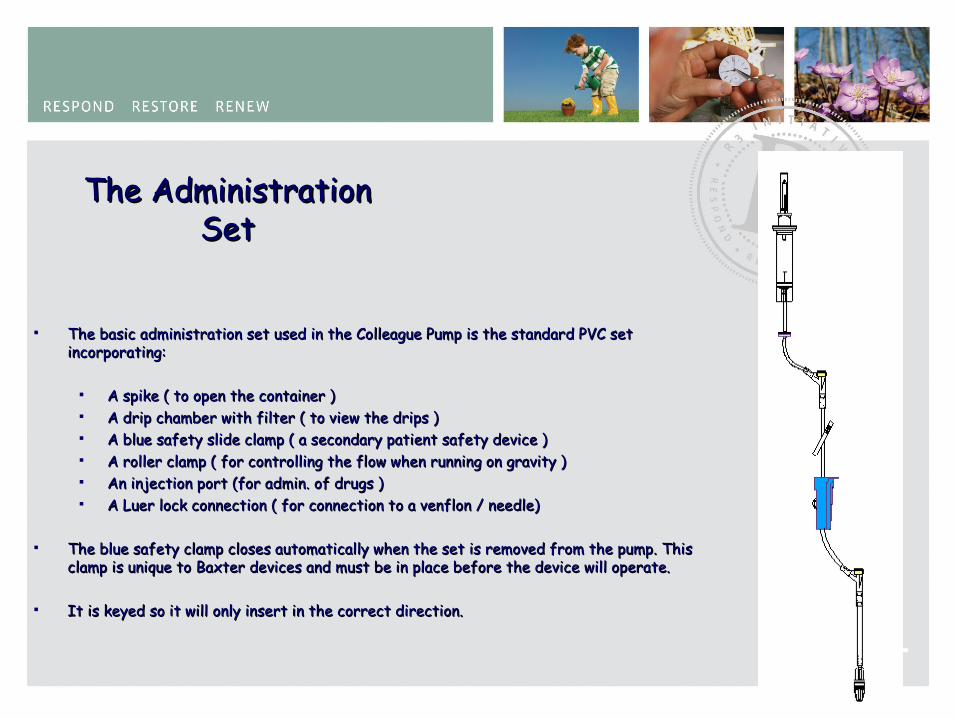
The Administration The Administration SetSet
The basic administration set used in the Colleague Pump is the standard PVC set The basic administration set used in the Colleague Pump is the standard PVC set incorporating:incorporating:
A spike ( to open the container )A spike ( to open the container ) A drip chamber with filter ( to view the drips )A drip chamber with filter ( to view the drips ) A blue safety slide clamp ( a secondary patient safety device )A blue safety slide clamp ( a secondary patient safety device ) A roller clamp ( for controlling the flow when running on gravity ) A roller clamp ( for controlling the flow when running on gravity ) An injection port (for admin. of drugs )An injection port (for admin. of drugs ) A Luer lock connection ( for connection to a venflon / needle)A Luer lock connection ( for connection to a venflon / needle)
The blue safety clamp closes automatically when the set is removed from the pump. This The blue safety clamp closes automatically when the set is removed from the pump. This clamp is unique to Baxter devices and must be in place before the device will operate. clamp is unique to Baxter devices and must be in place before the device will operate.
It is keyed so it will only insert in the correct direction.It is keyed so it will only insert in the correct direction.
13
Infusion Parameters The key parameters for an infusion:The key parameters for an infusion:
The The VolumeVolume of solution to be delivered to the patient. of solution to be delivered to the patient. The The RateRate of delivery. of delivery.
In the simplest form these are given in Millilitres (ml) and Millilitres per hour In the simplest form these are given in Millilitres (ml) and Millilitres per hour (ml/hr), but may be prescribed and programmed differently into the pump. (ml/hr), but may be prescribed and programmed differently into the pump.
The volume and rate are keyed into the pump and the pump is started.The volume and rate are keyed into the pump and the pump is started.
Under normal circumstances the infusion will start and run for the duration of Under normal circumstances the infusion will start and run for the duration of the infusion.the infusion. For example: Volume = 1000ml, Rate = 125ml/hrFor example: Volume = 1000ml, Rate = 125ml/hr
The infusion will run for 8 hours. The infusion will run for 8 hours. MOVIEMOVIE

14
Colleague MovieColleague Movie

15

16
Movie Quiz??Movie Quiz??
1.1. What kind of sets are used in the Colleague What kind of sets are used in the Colleague infusion Pump?infusion Pump?
2.2. What is the core technology in the Colleague?What is the core technology in the Colleague?3.3. What is the basis of the Shuttle?What is the basis of the Shuttle?4.4. How many parts are 1ml of fluid resolved How many parts are 1ml of fluid resolved
into?into?5.5. What is unique about the loading of the What is unique about the loading of the
administration set?administration set?6.6. What safety feature exists on all Colleague What safety feature exists on all Colleague
admin. sets?admin. sets?7.7. How many displays are there on Colleague? How many displays are there on Colleague? 8.8. What are they? What are they?
9.9. What is the purpose of Pump Personalities?What is the purpose of Pump Personalities?10.10. How many events are recorded in Event How many events are recorded in Event
History?History?

17
1.1. What kind of sets are used in the Colleague infusion What kind of sets are used in the Colleague infusion Pump?Pump?
2.2. What is the core technology in the Colleague?What is the core technology in the Colleague?3.3. What is the basis of the Shuttle?What is the basis of the Shuttle?4.4. How many parts are 1ml of fluid resolved into?How many parts are 1ml of fluid resolved into?5.5. What is unique about the loading of the What is unique about the loading of the
administration set?administration set?6.6. What safety feature exists on all Colleague admin. What safety feature exists on all Colleague admin.
sets?sets?7.7. How many displays are there on Colleague? How many displays are there on Colleague? 8.8. What are they? What are they?
9.9. What is the purpose of Pump Personalities?What is the purpose of Pump Personalities?10.10. How many events are recorded in Event History?How many events are recorded in Event History?
1.1. Standard gravity setStandard gravity set
2.2. The ShuttleThe Shuttle3.3. Two V blocksTwo V blocks4.4. 3,414 parts3,414 parts
5.5. It is automaticIt is automatic
6.6. The blue ‘ON/OFF’ safety clampThe blue ‘ON/OFF’ safety clamp7.7. TwoTwo8.8. Large graphic & Vacuum fluorescentLarge graphic & Vacuum fluorescent
9.9. Means of customizing the pumpMeans of customizing the pump
10.10. Up to 1000 eventsUp to 1000 events

18
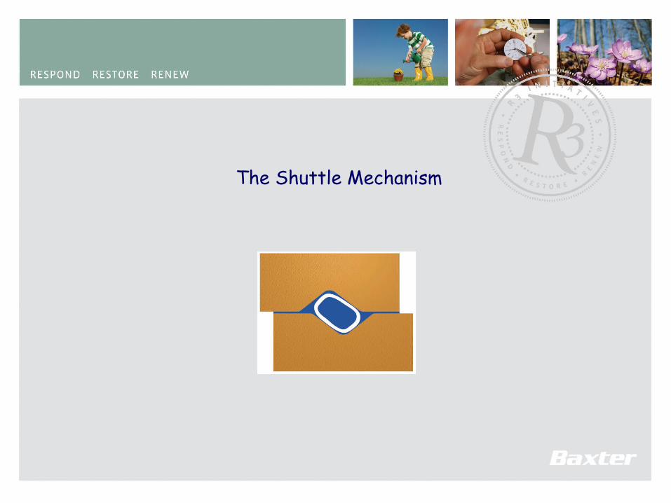
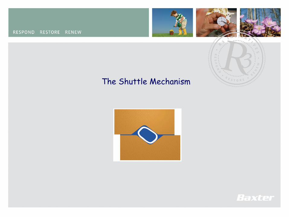
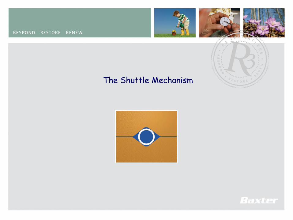
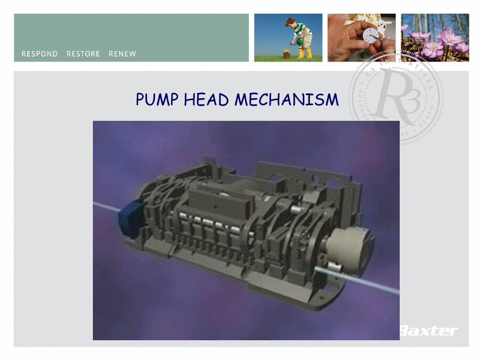
PUMP HEAD MECHANISM
Why the Shuttle?Why the Shuttle?
19
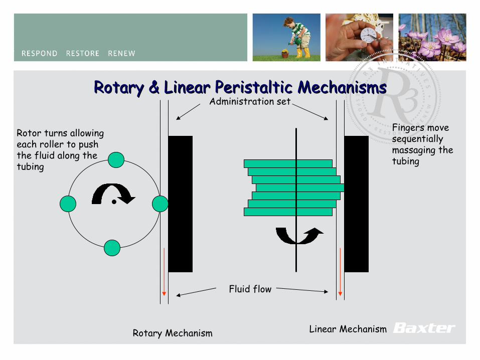
Rotary & Linear Peristaltic MechanismsRotary & Linear Peristaltic Mechanisms
Rotary Mechanism Linear Mechanism
Administration set
Fingers movesequentiallymassaging thetubing
Rotor turns allowingeach roller to pushthe fluid along thetubing
Fluid flow
20
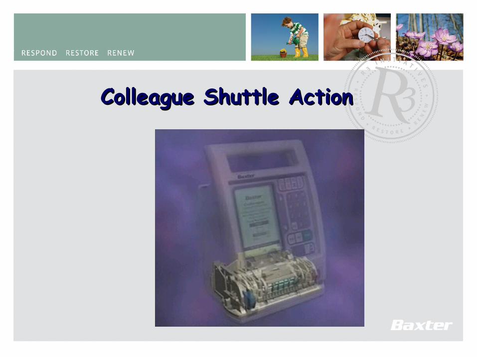
Colleague Shuttle ActionColleague Shuttle Action

21
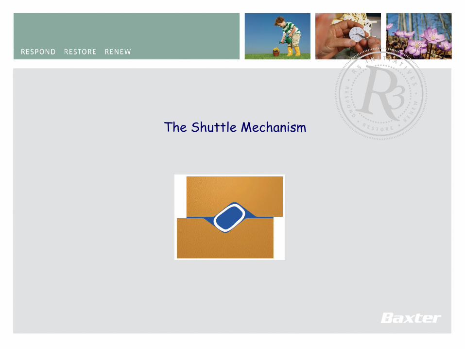
The Shuttle Mechanism
22
The Shuttle Mechanism

23
The Shuttle Mechanism
24
The Shuttle Mechanism
25
The Shuttle Mechanism
26
The Shuttle Mechanism
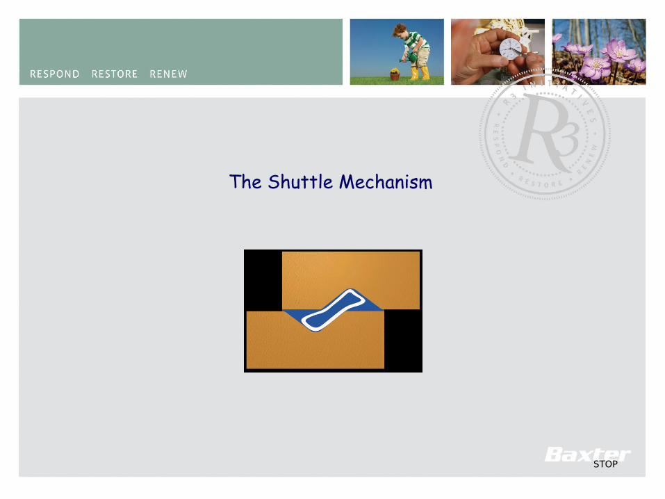
27STOP
The Shuttle Mechanism
28
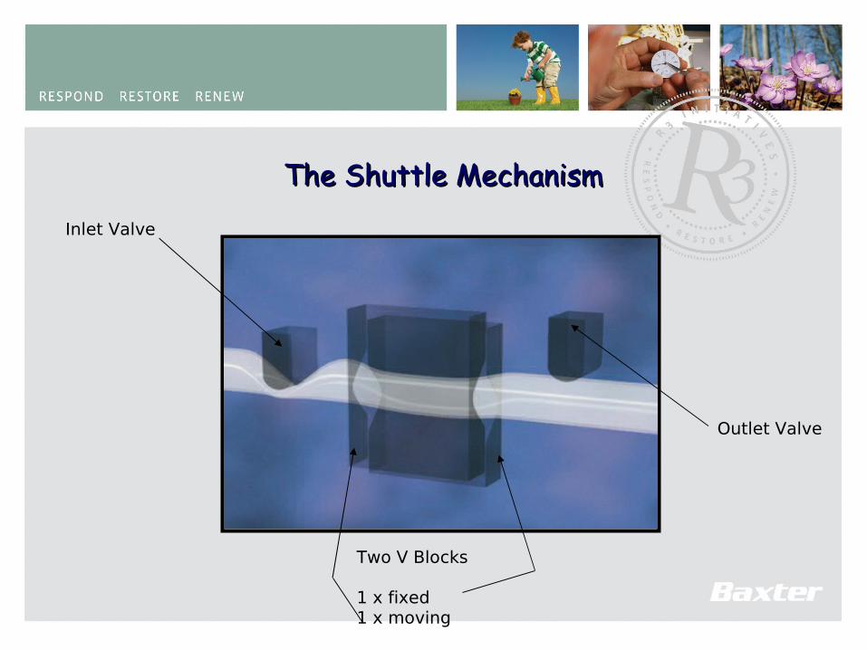
The Shuttle MechanismThe Shuttle Mechanism
Two V Blocks
1 x fixed1 x moving
Inlet Valve
Outlet Valve
29
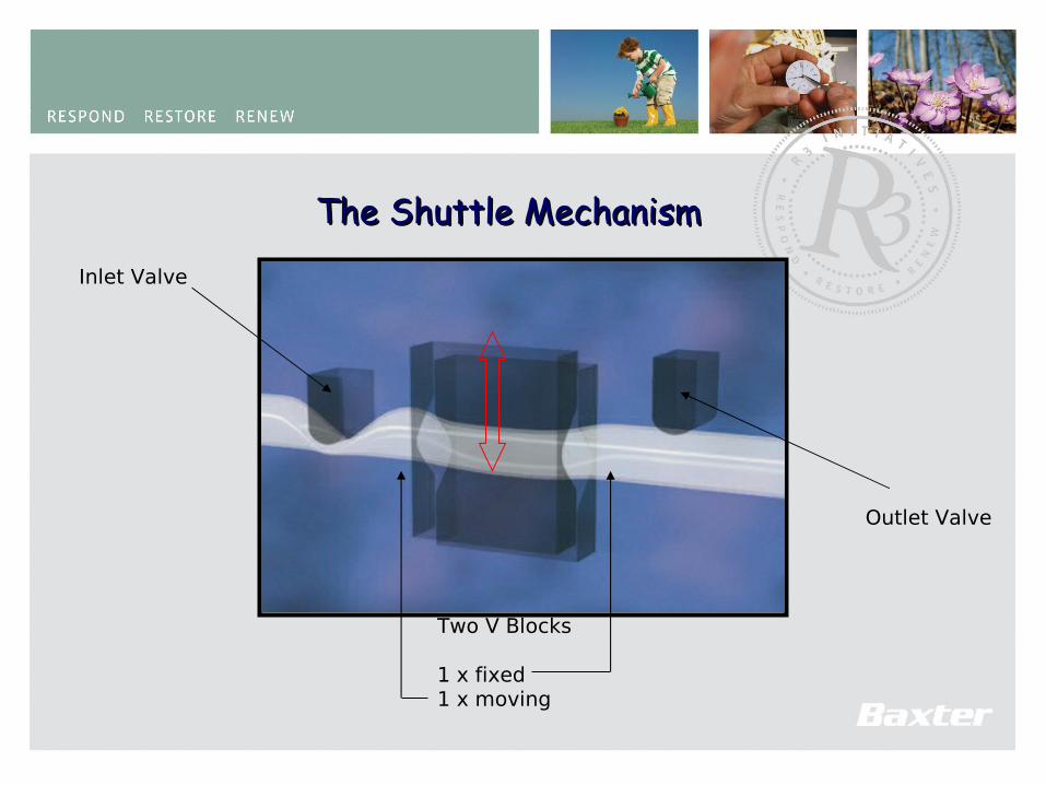
The Shuttle MechanismThe Shuttle Mechanism
Two V Blocks
1 x fixed1 x moving
Inlet Valve
Outlet Valve

30
The Shuttle MechanismThe Shuttle Mechanism
Two V Blocks
1 x fixed1 x moving
Inlet Valve
Outlet Valve
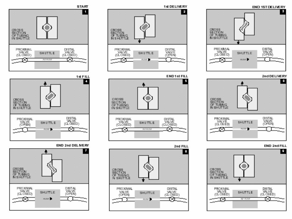
31

32
ColleagueColleague Technical InformationTechnical Information
Shuttle TechnologyShuttle Technology
Benefits:Benefits:
Maintain accurate delivery over 72 HrsMaintain accurate delivery over 72 Hrs Micro-Macro Flow Rates (0.1ml/Hr-1200ml/Hr)Micro-Macro Flow Rates (0.1ml/Hr-1200ml/Hr) Uses inexpensive pump compatible gravity giving sets.Uses inexpensive pump compatible gravity giving sets.
33
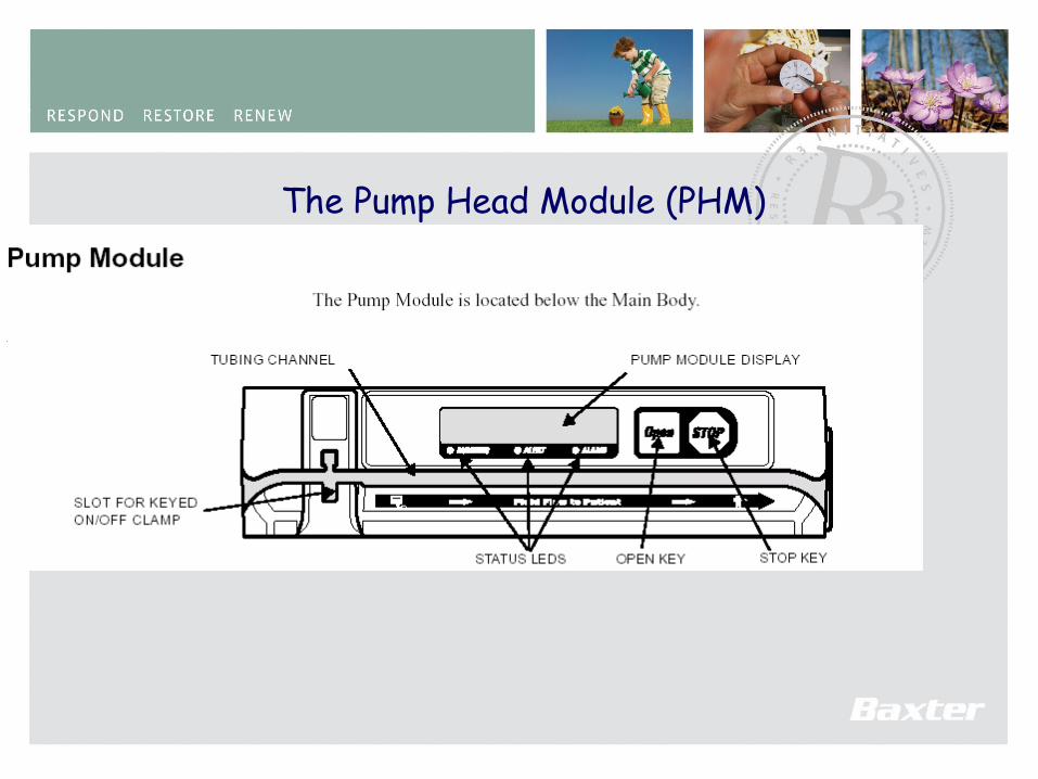
The Pump Head Module (PHM)
34
35
PUMP HEAD MECHANISM
36
PUMP HEAD MECHANISM
Outlet Valve
FlowTube Loading Guides Tube Loading Guides
Proximal Distal
On/Off Clamp Slot
Tubing Senso
r Lever
Inlet Valve
Tubing S
ensor Lev
er
Shuttle
Upstr Occl S
ensor
Dwnstr Occl S
ensor
Temp Sensor
Temp Sensor
Air Sensors
37
PUMP HEAD MECHANISM
• Occlusion SensorsOcclusion Sensors• Temperature SensorsTemperature Sensors• Air SensorsAir Sensors..
38
PUMP HEAD MECHANISM - Occlusion Sensors
Outlet Valve
FlowTube Loading Guides Tube Loading Guides
Proximal Distal
On/Off Clamp Slot
Tubing Senso
r Lever
Inlet Valve
Tubing Senso
r Lever
Shuttle
Upstr Occl S
ensor
Dwnstr Occl S
ensor
Temp Sensor
Temp Sensor
Air Sensors

39
Occlusion DetectionOcclusion Detection Cantilever beam strain gauge transducersCantilever beam strain gauge transducers• Upstream and downstream transducers are Zeroed at the beginning of an Upstream and downstream transducers are Zeroed at the beginning of an
infusion.infusion.• Three sensitivity levels for downstream occlusionThree sensitivity levels for downstream occlusion• Flow rate also influences downstream occlusion sensitivity.Flow rate also influences downstream occlusion sensitivity.
40
PUMP HEAD MECHANISM - PUMP HEAD MECHANISM - Temperature SensorsTemperature Sensors
Outlet Valve
FlowTube Loading Guides Tube Loading Guides
Proximal Distal
On/Off Clamp Slot
Tubing Senso
r Lever
Inlet Valve
Tubing S
ensor Lev
er
Shuttle
Upstr Occl S
ensor
Dwnstr Occl S
ensor
Temp Sensor
Temp Sensor
Air Sensors
Shuts Pump down if outside 15o – 38o CCompensates occlusion reaction for changes in tube characteristics
41
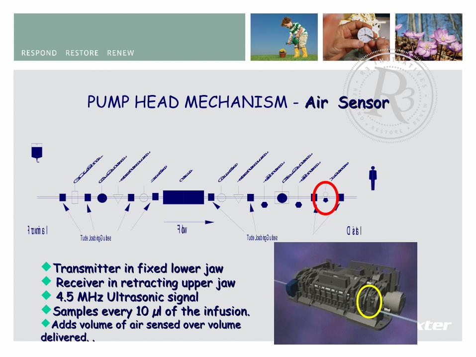
PUMP HEAD MECHANISM - Air SensorAir Sensor
Outlet Valve
FlowTube Loading Guides Tube Loading Guides
Proximal Distal
On/Off Clamp Slot
Tubing Senso
r Lever
Inlet Valve
Tubing Senso
r Lever
ShuttleUpstr Occl S
ensor
Dwnstr Occl S
ensor
Temp Sensor
Temp Sensor
Air Sensors
Transmitter in fixed lower jawTransmitter in fixed lower jaw Receiver in retracting upper jawReceiver in retracting upper jaw 4.5 MHz Ultrasonic signal4.5 MHz Ultrasonic signalSamples every 10 µl of the infusion.Samples every 10 µl of the infusion.Adds volume of air sensed over volume Adds volume of air sensed over volume delivered. .delivered. .

42
PUMP HEAD MECHANISM - Air SensorAir Sensor
Small Daughter PCB on PHM PCBSmall Daughter PCB on PHM PCB Conditions Tx and Rx analogue signals for Conditions Tx and Rx analogue signals for further processing on PHM PCBfurther processing on PHM PCB
Air in Line PCB (AIL PCB)Air in Line PCB (AIL PCB)
43
PUMP HEAD MECHANISM - PUMP HEAD MECHANISM - Air SensorAir Sensor

44
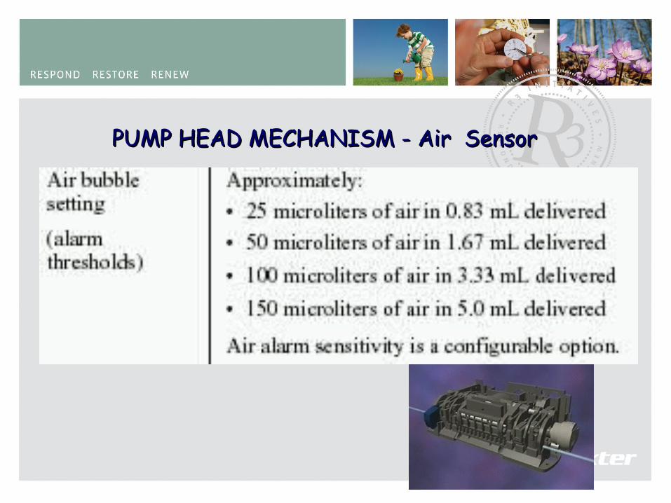
Accumulative Air Bubble SizeAccumulative Air Bubble SizeAir setting to 25 microlitresAir setting to 25 microlitres
Air setting to 50 microlitresAir setting to 50 microlitres
Air setting to 100 microlitresAir setting to 100 microlitres
Air setting to 150 microlitresAir setting to 150 microlitres
Air bubble in any 830 microlitresAir bubble in any 830 microlitres
Air bubble in any 1.67 millilitresAir bubble in any 1.67 millilitres
Air bubble in any 3.34 millilitresAir bubble in any 3.34 millilitres
Air bubble in any 5.0 millilitresAir bubble in any 5.0 millilitres

45
Accumulative Air Bubble SizeAccumulative Air Bubble SizeAir setting to 25 microlitresAir setting to 25 microlitres
Air bubble in any 830 microlitresAir bubble in any 830 microlitres
AIR ALARMAIR ALARM
AIR ALARMAIR ALARM
AIR ALARMAIR ALARM
NO AIR ALARMNO AIR ALARM
46
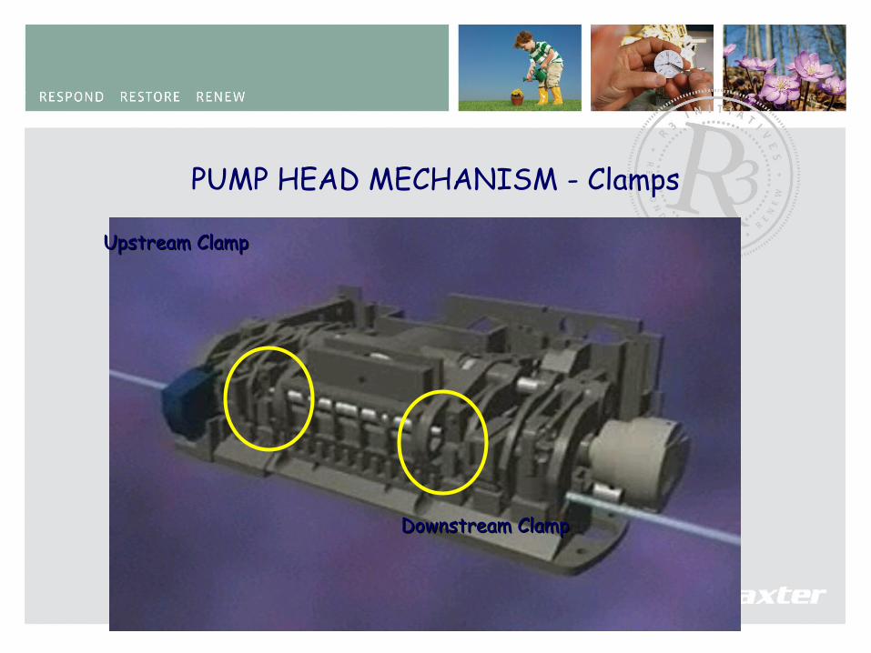
PUMP HEAD MECHANISM - Clamps
Upstream ClampUpstream Clamp
Downstream ClampDownstream Clamp
47
PUMP HEAD MECHANISM
Outlet Valve
FlowTube Loading Guides Tube Loading Guides
Proximal Distal
On/Off Clamp Slot
Tubing Senso
r Lever
Inlet Valve
Tubing Senso
r Lever
Shuttle
Upstr Occl S
ensor
Dwnstr Occl S
ensor
Temp Sensor
Temp Sensor
Air Sensors
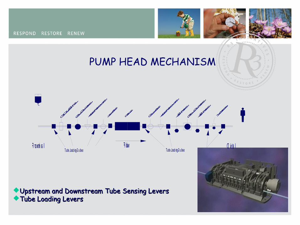
Upstream and Downstream Tube Sensing LeversUpstream and Downstream Tube Sensing LeversTube Loading LeversTube Loading Levers
48
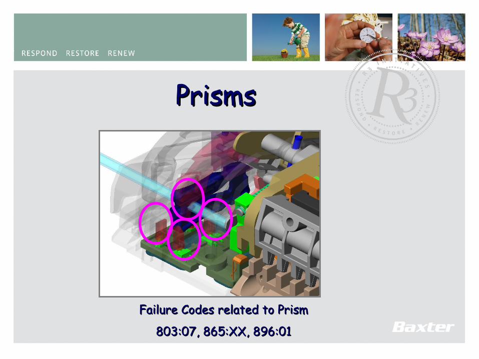
PrismsPrisms
Failure Codes related to PrismFailure Codes related to Prism
803:07, 865:XX, 896:01803:07, 865:XX, 896:01

49
Prism and Flex ContPrism and Flex Cont.
50
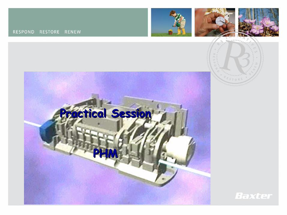
Practical SessionPractical Session
PHMPHM
51
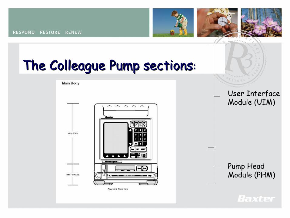
The Colleague Pump sectionsThe Colleague Pump sections::
User InterfaceModule (UIM)
Pump HeadModule (PHM)
52
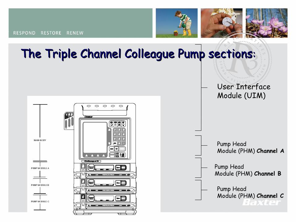
The Triple Channel Colleague Pump sectionsThe Triple Channel Colleague Pump sections::
User InterfaceModule (UIM)
Pump HeadModule (PHM) Channel A
Pump HeadModule (PHM) Channel B
Pump HeadModule (PHM) Channel C
53
Device Description – Front faceDevice Description – Front face
Graphic DisplayGraphic Display
PHM LEDsPHM LEDs
Fixed function keysFixed function keysScrollbar Scrollbar softkeyssoftkeys
Options Options softkeyssoftkeys
Vacuum Florescent Vacuum Florescent displaydisplay
Keyed safety side Keyed safety side clampclamp
Numeric keysNumeric keys
Rate, Volume & Rate, Volume & StartStart keys keys
On/off On/off keykey
Stop, Open keysStop, Open keys
Tubing channelTubing channel
Status indicatorStatus indicator
54
Device Description – RearDevice Description – Rear
PumpheadPumpheadModule (PHM)Module (PHM)
Volume ControlVolume Control
Mains FusesMains Fuses
Contrast Contrast ControlControl
Speaker VentSpeaker Vent
IV Pole Clamp KnobIV Pole Clamp Knob
Power Cord Power Cord RestraintRestraint
Power CordPower Cord
Backup Buzzer ventBackup Buzzer vent
ISO Comm ISO Comm PortPort
Lock Knob ‘Wings’Lock Knob ‘Wings’
Panel Lock KeyPanel Lock Key
Bed End PlateBed End Plate
Serial Number Serial Number LabelLabel
Manual tube Manual tube releaserelease
HandleHandle
FeetFeet
55
Serial Number FormatSerial Number Format
56
Device Description – Display & SoftkeysDevice Description – Display & Softkeys
Information lineInformation line
Main Display AreaMain Display Area
Prompt LinePrompt Line
Softkey legend lineSoftkey legend line
57
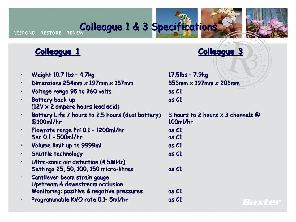
Colleague 1 & 3 SpecificationsColleague 1 & 3 Specifications
Colleague 1Colleague 1 Colleague 3Colleague 3
• Weight 10.7 lbs – 4.7kgWeight 10.7 lbs – 4.7kg 17.5lbs – 7.9kg17.5lbs – 7.9kg• Dimensions 254mm x 197mm x 187mmDimensions 254mm x 197mm x 187mm 353mm x 197mm x 203mm353mm x 197mm x 203mm• Voltage range 95 to 260 voltsVoltage range 95 to 260 volts as C1as C1• Battery back-up Battery back-up as C1as C1
(12V x 2 ampere hours lead acid)(12V x 2 ampere hours lead acid)• Battery Life 7 hours to 2.5 hours (dual battery)Battery Life 7 hours to 2.5 hours (dual battery) 3 hours to 2 hours x 3 channels @ 3 hours to 2 hours x 3 channels @
@100ml/hr@100ml/hr 100ml/hr100ml/hr• Flowrate range Pri 0.1 – 1200ml/hrFlowrate range Pri 0.1 – 1200ml/hr as C1as C1
Sec 0.1 – 500ml/hrSec 0.1 – 500ml/hr as C1as C1• Volume limit up to 9999mlVolume limit up to 9999ml as C1as C1• Shuttle technologyShuttle technology as C1as C1• Ultra-sonic air detection (4.5MHz) Ultra-sonic air detection (4.5MHz)
Settings 25, 50, 100, 150 micro-litresSettings 25, 50, 100, 150 micro-litres as C1as C1• Cantilever beam strain gauge Cantilever beam strain gauge
Upstream & downstream occlusion Upstream & downstream occlusion Monitoring: positive & negative pressuresMonitoring: positive & negative pressures as C1as C1
• Programmable KVO rate 0.1- 5ml/hrProgrammable KVO rate 0.1- 5ml/hr as C1as C1
58
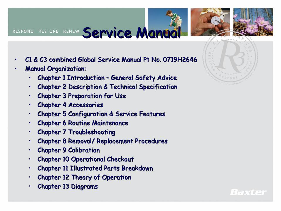
Service ManualService Manual• C1 & C3 combined Global Service Manual Pt No. 0719H2646C1 & C3 combined Global Service Manual Pt No. 0719H2646• Manual Organization:Manual Organization:
• Chapter 1 Introduction – General Safety AdviceChapter 1 Introduction – General Safety Advice• Chapter 2 Description & Technical SpecificationChapter 2 Description & Technical Specification• Chapter 3 Preparation for UseChapter 3 Preparation for Use• Chapter 4 AccessoriesChapter 4 Accessories• Chapter 5 Configuration & Service FeaturesChapter 5 Configuration & Service Features• Chapter 6 Routine MaintenanceChapter 6 Routine Maintenance• Chapter 7 TroubleshootingChapter 7 Troubleshooting• Chapter 8 Removal/ Replacement ProceduresChapter 8 Removal/ Replacement Procedures• Chapter 9 CalibrationChapter 9 Calibration• Chapter 10 Operational CheckoutChapter 10 Operational Checkout• Chapter 11 Illustrated Parts BreakdownChapter 11 Illustrated Parts Breakdown• Chapter 12 Theory of OperationChapter 12 Theory of Operation• Chapter 13 DiagramsChapter 13 Diagrams
59
Colleague Alarms & AlertsColleague Alarms & Alerts
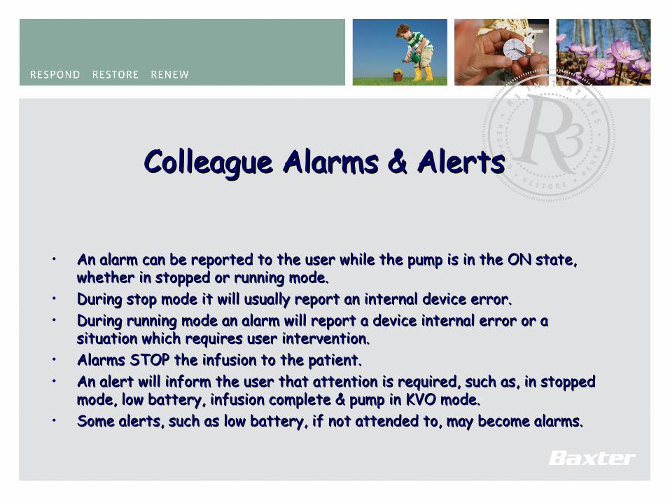
• An alarm can be reported to the user while the pump is in the ON state, An alarm can be reported to the user while the pump is in the ON state, whether in stopped or running mode.whether in stopped or running mode.
• During stop mode it will usually report an internal device error.During stop mode it will usually report an internal device error.• During running mode an alarm will report a device internal error or a During running mode an alarm will report a device internal error or a
situation which requires user intervention.situation which requires user intervention.• Alarms STOP the infusion to the patient.Alarms STOP the infusion to the patient.• An alert will inform the user that attention is required, such as, in stopped An alert will inform the user that attention is required, such as, in stopped
mode, low battery, infusion complete & pump in KVO mode.mode, low battery, infusion complete & pump in KVO mode.• Some alerts, such as low battery, if not attended to, may become alarms.Some alerts, such as low battery, if not attended to, may become alarms.
60
Colleague Alarms & AlertsColleague Alarms & Alerts
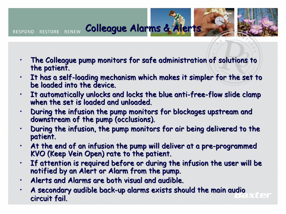
• The Colleague pump monitors for safe administration of solutions to The Colleague pump monitors for safe administration of solutions to the patient.the patient.
• It has a self-loading mechanism which makes it simpler for the set to It has a self-loading mechanism which makes it simpler for the set to be loaded into the device.be loaded into the device.
• It automatically unlocks and locks the blue anti-free-flow slide clamp It automatically unlocks and locks the blue anti-free-flow slide clamp when the set is loaded and unloaded.when the set is loaded and unloaded.
• During the infusion the pump monitors for blockages upstream and During the infusion the pump monitors for blockages upstream and downstream of the pump (occlusions).downstream of the pump (occlusions).
• During the infusion, the pump monitors for air being delivered to the During the infusion, the pump monitors for air being delivered to the patient.patient.
• At the end of an infusion the pump will deliver at a pre-programmed At the end of an infusion the pump will deliver at a pre-programmed KVO (Keep Vein Open) rate to the patient.KVO (Keep Vein Open) rate to the patient.
• If attention is required before or during the infusion the user will be If attention is required before or during the infusion the user will be notified by an Alert or Alarm from the pump.notified by an Alert or Alarm from the pump.
• Alerts and Alarms are both visual and audible.Alerts and Alarms are both visual and audible.• A secondary audible back-up alarms exists should the main audio A secondary audible back-up alarms exists should the main audio
circuit fail.circuit fail.

61
Switching on the ColleagueSwitching on the Colleague
• Controls and Operating the ColleagueControls and Operating the Colleague
62
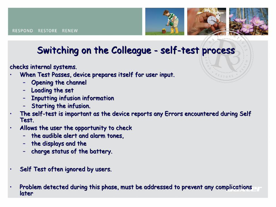
Switching on the Colleague - self-test processSwitching on the Colleague - self-test processchecks internal systems.checks internal systems.• When Test Passes, device prepares itself for user input.When Test Passes, device prepares itself for user input.
– Opening the channelOpening the channel– Loading the setLoading the set– Inputting infusion informationInputting infusion information– Starting the infusion.Starting the infusion.
• The self-test is important as the device reports any Errors encountered during Self The self-test is important as the device reports any Errors encountered during Self Test.Test.
• Allows the user the opportunity to check Allows the user the opportunity to check – the audible alert and alarm tones, the audible alert and alarm tones, – the displays and the the displays and the – charge status of the battery.charge status of the battery.
• Self Test often ignored by users.Self Test often ignored by users.
• Problem detected during this phase, must be addressed to prevent any complications Problem detected during this phase, must be addressed to prevent any complications laterlater
63
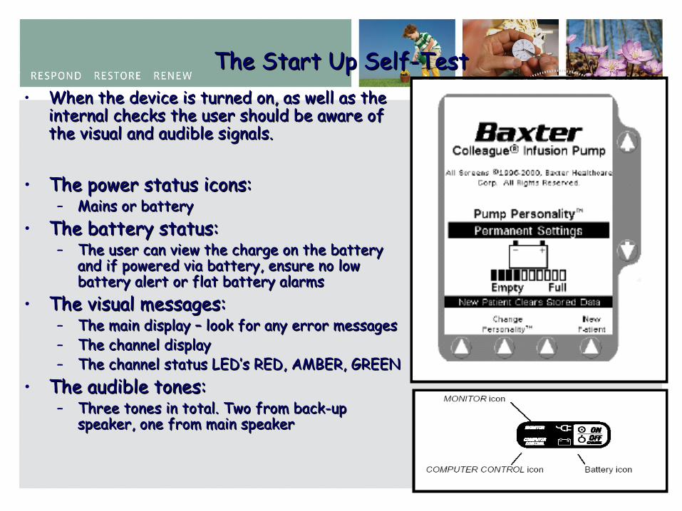
The Start Up Self-TestThe Start Up Self-Test• When the device is turned on, as well as the When the device is turned on, as well as the
internal checks the user should be aware of internal checks the user should be aware of the visual and audible signals.the visual and audible signals.
• The power status icons:The power status icons:– Mains or batteryMains or battery
• The battery status:The battery status:– The user can view the charge on the battery The user can view the charge on the battery
and if powered via battery, ensure no low and if powered via battery, ensure no low battery alert or flat battery alarmsbattery alert or flat battery alarms
• The visual messages:The visual messages:– The main display – look for any error messagesThe main display – look for any error messages– The channel displayThe channel display– The channel status LED’s RED, AMBER, GREENThe channel status LED’s RED, AMBER, GREEN
• The audible tones:The audible tones:– Three tones in total. Two from back-up Three tones in total. Two from back-up
speaker, one from main speakerspeaker, one from main speaker
64
Opening the Channel & Loading the SetOpening the Channel & Loading the Set
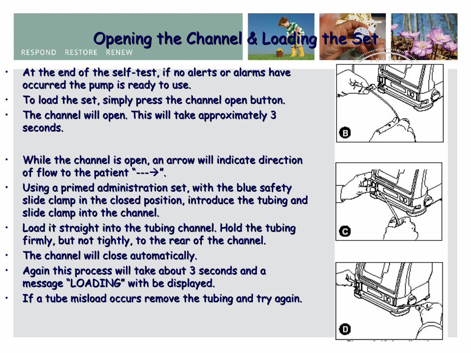
• At the end of the self-test, if no alerts or alarms have At the end of the self-test, if no alerts or alarms have occurred the pump is ready to use.occurred the pump is ready to use.
• To load the set, simply press the channel open button.To load the set, simply press the channel open button.• The channel will open. This will take approximately 3 The channel will open. This will take approximately 3
seconds.seconds.
• While the channel is open, an arrow will indicate direction While the channel is open, an arrow will indicate direction of flow to the patient “---of flow to the patient “---”. ”.
• Using a primed administration set, with the blue safety Using a primed administration set, with the blue safety slide clamp in the closed position, introduce the tubing and slide clamp in the closed position, introduce the tubing and slide clamp into the channel.slide clamp into the channel.
• Load it straight into the tubing channel. Hold the tubing Load it straight into the tubing channel. Hold the tubing firmly, but not tightly, to the rear of the channel.firmly, but not tightly, to the rear of the channel.
• The channel will close automatically.The channel will close automatically.• Again this process will take about 3 seconds and a Again this process will take about 3 seconds and a
message “LOADING” with be displayed.message “LOADING” with be displayed.• If a tube misload occurs remove the tubing and try again. If a tube misload occurs remove the tubing and try again.
65
Keying in the Infusion Parameter & Starting The Pump Keying in the Infusion Parameter & Starting The Pump
• With the set loaded the pump is ready for the parameters to be With the set loaded the pump is ready for the parameters to be keyed in. keyed in.
• From the Main Screen, by pressing Vol. key and using the numeric From the Main Screen, by pressing Vol. key and using the numeric keys, enter the desired volume in millilitres (e.g. 100ml).keys, enter the desired volume in millilitres (e.g. 100ml).
• If an error is made press the CLR key on the keypad and re-enter If an error is made press the CLR key on the keypad and re-enter the volume.the volume.
• Press the RATE key and enter the desired rate (e.g. 125ml/hr).Press the RATE key and enter the desired rate (e.g. 125ml/hr).• Open the roller clamp on the set and press the green START key.Open the roller clamp on the set and press the green START key.• The infusion will commence.The infusion will commence.• The Stop sign will change to a drip icon.The Stop sign will change to a drip icon.• The green running LED will illuminate.The green running LED will illuminate.• Drips will appear in the drip chamber.Drips will appear in the drip chamber.• The ‘Time Remaining’ and ‘Volume to be Infused’ will count down.The ‘Time Remaining’ and ‘Volume to be Infused’ will count down.• The rate that the pump is running at will appear in the PHM display.The rate that the pump is running at will appear in the PHM display.• Fluid will be delivered to the patient. Fluid will be delivered to the patient.
66
Testing the Alarms and AlertsTesting the Alarms and Alerts
• The ALARM TONE is three rapid beeps, a gap and three rapid beeps….The ALARM TONE is three rapid beeps, a gap and three rapid beeps….
• The Functional Test for a Downstream Occlusion.The Functional Test for a Downstream Occlusion.
• With the pump running, pinch the tubing downstream of the pump.With the pump running, pinch the tubing downstream of the pump.• The pump will stop and ‘Downstream Occlusion’ will be displayed together with The pump will stop and ‘Downstream Occlusion’ will be displayed together with
an audible alarm. The RED LED on the PHM will illuminate.an audible alarm. The RED LED on the PHM will illuminate.• Release the tubing and the pump will re-start automatically.Release the tubing and the pump will re-start automatically.
The Functional Test for an Upstream Occlusion.The Functional Test for an Upstream Occlusion.
• With the pump running, pinch the tubing above the pump.With the pump running, pinch the tubing above the pump.• The pump will stop and ‘Upstream Occlusion’ will be displayed together with The pump will stop and ‘Upstream Occlusion’ will be displayed together with
an audible alarm.an audible alarm.• Release the tubing and the pump this time WILL NOT restart.Release the tubing and the pump this time WILL NOT restart.• You must press the primary or rate key and start key to restart the pump.You must press the primary or rate key and start key to restart the pump.
67
Testing the Alarms and AlertsTesting the Alarms and Alerts
The Functional Test for the Air Detection System.The Functional Test for the Air Detection System.
• Again with the pump running press the rate key followed by 500 on the Again with the pump running press the rate key followed by 500 on the numeric keypad.numeric keypad.
• The pump will alert with the message ‘New Rate’.The pump will alert with the message ‘New Rate’.• The delivery rate will not change until the start key is pressed.The delivery rate will not change until the start key is pressed.• With the pump running at the new rate, invert the drip chamber so air is With the pump running at the new rate, invert the drip chamber so air is
pumped down the giving set.pumped down the giving set.• When an air bubble approximately 25mm in length is visible in the set When an air bubble approximately 25mm in length is visible in the set
below the drip chamber return the drip chamber to its normal position.below the drip chamber return the drip chamber to its normal position.• Allow the pump to run until an ‘Air Detected’ alarm occurs.Allow the pump to run until an ‘Air Detected’ alarm occurs.
• Press the Alarm Silence key and the audible alarm will be muted for two Press the Alarm Silence key and the audible alarm will be muted for two minutes.minutes.
68
Testing the Alarms and AlertsTesting the Alarms and Alerts
Dealing with an Air AlarmDealing with an Air Alarm
• The screen will display DO YOU WANT TO ADVANCE THE AIR TO VIEW The screen will display DO YOU WANT TO ADVANCE THE AIR TO VIEW THE AIR BUBBLE?THE AIR BUBBLE?
• Press the YES key (up arrow soft key)Press the YES key (up arrow soft key)• Press and Press and holdhold the Advance Air soft key. the Advance Air soft key.• The pump will run at the programmed rate and the air bubble will travel The pump will run at the programmed rate and the air bubble will travel
along the tubing, exiting the pump channel.along the tubing, exiting the pump channel.• This allows the user to view the air bubble size and make a clinical decision This allows the user to view the air bubble size and make a clinical decision
regarding the air alarm.regarding the air alarm.• The advance air key will allow no more than 400ul (microlitres) to be The advance air key will allow no more than 400ul (microlitres) to be
advanced.advanced.• Once the air bubble has finished advancing, the pump will display FLUID Once the air bubble has finished advancing, the pump will display FLUID
where it had previously displayed air.where it had previously displayed air.• The pump will be ready to start. This time the start key need only be The pump will be ready to start. This time the start key need only be
pressed to resume the infusion.pressed to resume the infusion.
69
Testing the AlertsTesting the Alerts
• The ALERT TONE is a single tone then a long space, repeatedly.The ALERT TONE is a single tone then a long space, repeatedly.• The main alerts on the device are:The main alerts on the device are:• 2 minute stopped mode2 minute stopped mode• KVO modeKVO mode• Low batteryLow battery
• An alert message indicates that the pump requires attention.An alert message indicates that the pump requires attention.• Program the pump to deliver 2mls at a rate of 500ml/hr.Program the pump to deliver 2mls at a rate of 500ml/hr.• Start the pump.Start the pump.• After the 2mls has been delivered the pump will enter KVO mode, the After the 2mls has been delivered the pump will enter KVO mode, the
alert LED will illuminate and the KVO rate will be displayed on the pump.alert LED will illuminate and the KVO rate will be displayed on the pump.
• The cause of an alert message should be investigated by the user.The cause of an alert message should be investigated by the user.• For example, if a battery low alert is ignored, it will become an alarm.For example, if a battery low alert is ignored, it will become an alarm.
70
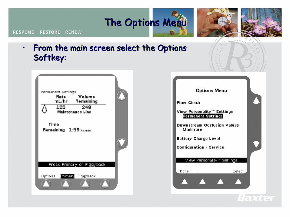
The Options MenuThe Options Menu
• From the main screen select the Options From the main screen select the Options Softkey:Softkey:
71
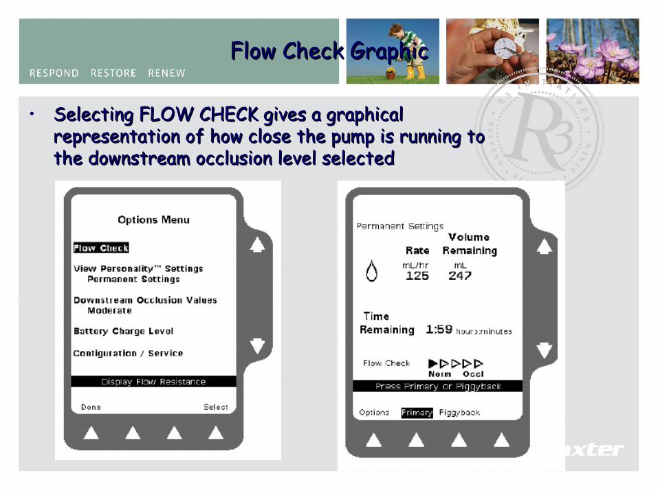
Flow Check GraphicFlow Check Graphic
• Selecting FLOW CHECK gives a graphical Selecting FLOW CHECK gives a graphical representation of how close the pump is running to representation of how close the pump is running to the downstream occlusion level selected the downstream occlusion level selected
72
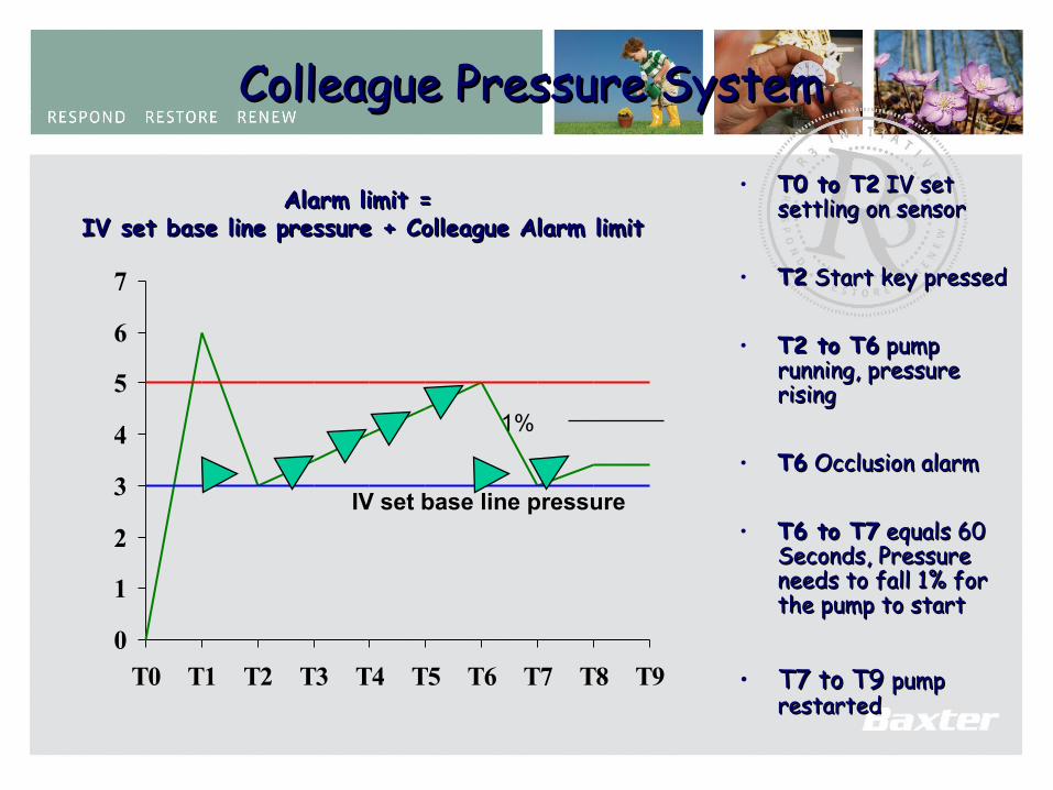
Colleague Pressure SystemColleague Pressure System
• T0 to T2T0 to T2 IV set IV set settling on sensorsettling on sensor
• T2T2 Start key pressed Start key pressed
• T2 to T6T2 to T6 pump pump running, pressure running, pressure risingrising
• T6T6 Occlusion alarm Occlusion alarm
• T6 to T7T6 to T7 equals 60 equals 60 Seconds, Pressure Seconds, Pressure needs to fall 1% for needs to fall 1% for the pump to startthe pump to start
• T7 to T9 T7 to T9 pump pump restartedrestarted
0
1
2
3
4
5
6
7
T0 T1 T2 T3 T4 T5 T6 T7 T8 T9
IV set base line pressure
Alarm limit = Alarm limit = IV set base line pressure + Colleague Alarm limitIV set base line pressure + Colleague Alarm limit
1%

ColleagueColleague®® Occlusion Occlusion PressurePressure

74
Pressure in the Pressure in the Body Body
• Arterial pressure Arterial pressure approx. 100mmHgapprox. 100mmHg
• Peripheral venous Peripheral venous pressure 5 -80 mmHgpressure 5 -80 mmHg
• Veins have mono-Veins have mono-directional flow, as the directional flow, as the veins are lined with veins are lined with valves called cusps.valves called cusps.

75
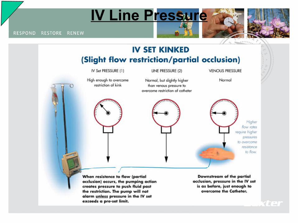
IV Line Pressure
76
IV Line Pressure
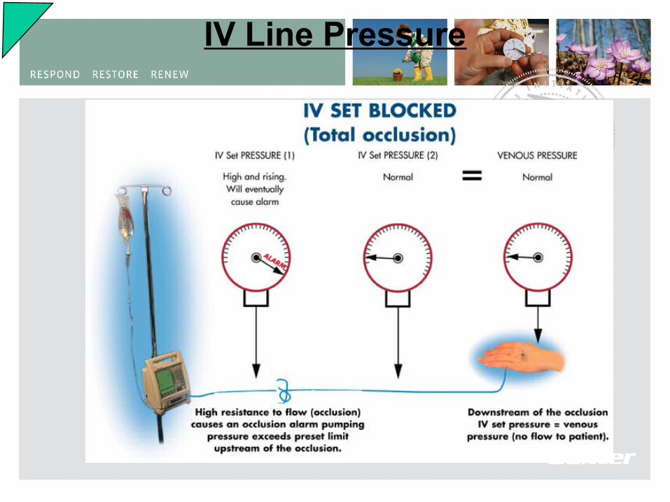
77
IV Line Pressure
78
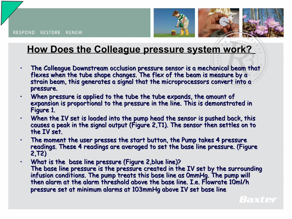
How Does the Colleague pressure system work? • The Colleague Downstream occlusion pressure sensor is a mechanical beam that The Colleague Downstream occlusion pressure sensor is a mechanical beam that
flexes when the tube shape changes. The flex of the beam is measure by a flexes when the tube shape changes. The flex of the beam is measure by a strain beam, this generates a signal that the microprocessors convert into a strain beam, this generates a signal that the microprocessors convert into a pressure.pressure.
• When pressure is applied to the tube the tube expands, the amount of When pressure is applied to the tube the tube expands, the amount of expansion is proportional to the pressure in the line. This is demonstrated in expansion is proportional to the pressure in the line. This is demonstrated in Figure 1.Figure 1.
• When the IV set is loaded into the pump head the sensor is pushed back, this When the IV set is loaded into the pump head the sensor is pushed back, this causes a peak in the signal output (Figure 2,T1). The sensor then settles on to causes a peak in the signal output (Figure 2,T1). The sensor then settles on to the IV set. the IV set.
• The moment the user presses the start button, the Pump takes 4 pressure The moment the user presses the start button, the Pump takes 4 pressure readings. These 4 readings are averaged to set the base line pressure. (Figure readings. These 4 readings are averaged to set the base line pressure. (Figure 2,T2)2,T2)
• What is the base line pressure (Figure 2,blue line)?What is the base line pressure (Figure 2,blue line)?The base line pressure is the pressure created in the IV set by the surrounding The base line pressure is the pressure created in the IV set by the surrounding infusion conditions. The pump treats this base line as 0mmHg. The pump will infusion conditions. The pump treats this base line as 0mmHg. The pump will then alarm at the alarm threshold above the base line. I.e. Flowrate 10ml/h then alarm at the alarm threshold above the base line. I.e. Flowrate 10ml/h pressure set at minimum alarms at 103mmHg above IV set base linepressure set at minimum alarms at 103mmHg above IV set base line
79
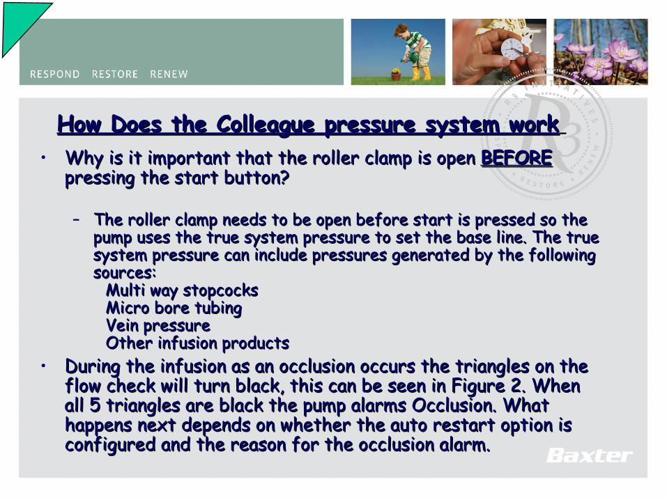
How Does the Colleague pressure system workHow Does the Colleague pressure system work • Why is it important that the roller clamp is open Why is it important that the roller clamp is open BEFOREBEFORE
pressing the start button?pressing the start button?
– The roller clamp needs to be open before start is pressed so the The roller clamp needs to be open before start is pressed so the pump uses the true system pressure to set the base line. The true pump uses the true system pressure to set the base line. The true system pressure can include pressures generated by the following system pressure can include pressures generated by the following sources:sources:
Multi way stopcocks Multi way stopcocks Micro bore tubingMicro bore tubingVein pressureVein pressureOther infusion productsOther infusion products
• During the infusion as an occlusion occurs the triangles on the During the infusion as an occlusion occurs the triangles on the flow check will turn black, this can be seen in Figure 2. When flow check will turn black, this can be seen in Figure 2. When all 5 triangles are black the pump alarms Occlusion. What all 5 triangles are black the pump alarms Occlusion. What happens next depends on whether the auto restart option is happens next depends on whether the auto restart option is configured and the reason for the occlusion alarm.configured and the reason for the occlusion alarm.

80
Colleague Pressure SystemColleague Pressure System
Rate Occ lus ion A larm Typical Tim e to M ax im um Tim e to
P ressure S etting A larm A c tivation A larm A c tivation
M inim um 103 m m Hg 4 m in 6 sec 7 m in 59 sec
1 m l/h M oderate 252 m m Hg 7 m in 24 sec 13 m in 44 sec
M ax im um 465 m m Hg 13 m in 48 sec 26 m in 58 sec
M inim um 206 m m Hg 0 m in 17 sec 0 m in 27 sec
25 m l/h M oderate 413 m m Hg 0 m in 32 sec 0 m in 52 sec
M ax im um 620 m m Hg 0 m in 47 sec 1 m in 12 sec
Rate Occ lus ion A larm Typical B olus M ax im um B olus
P ressure S ett ing V olum e V olum e
M inim um 103 m m Hg 0.057m l 0.16m l
1 m l/h M oderate 252 m m Hg 0.110m l 0.20m l
M ax im um 465 m m Hg 0.177m l 0.26m l
M inim um 206 m m Hg 0.079m l 0.20m l
25 m l/h M oderate 413 m m Hg 0.178m l 0.55m l
M ax im um 620 m m Hg 0.245m l 0.72m l
Time to Detect Downstream Occlusion Bolus Volume After Downstream Occlusion
Occlusion PressureOcclusion PressureClinical Importance of Occlusion pressure alarmsClinical Importance of Occlusion pressure alarms
Inform the user of non delivery of the prescriptionInform the user of non delivery of the prescriptionThe two factors that are Clinically importantThe two factors that are Clinically important
Time to AlarmTime to AlarmPost Occlusion BolusPost Occlusion Bolus
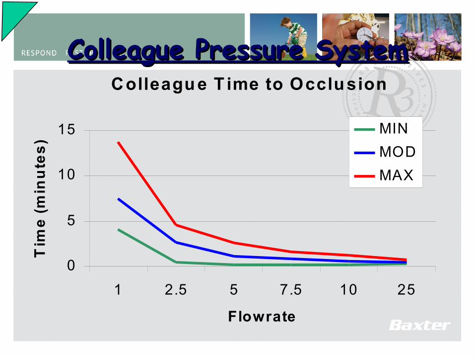
81
Colleague Pressure SystemColleague Pressure SystemColleagu e T ime to Occlusion
0
5
10
15
1 2.5 5 7.5 10 25
Flowrate
Tim
e (
min
ute
s)
MIN
MOD
MAX
82
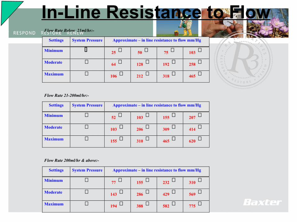
Flow Rate Below 21ml/hr:-
Settings System Pressure Approximate – in line resistance to flow mm/Hg
Minimum 25 50 75 103
Moderate 64 128 192 258
Maximum 106 212 318 465
Flow Rate 21-200ml/hr:-
Settings System Pressure Approximate – in line resistance to flow mm/Hg
Minimum 52 103 155 207
Moderate 103 206 309 414
Maximum 155 310 465 620
Flow Rate 200ml/hr & above:-
Settings System Pressure Approximate – in line resistance to flow mm/Hg
Minimum 77 155 232 310
Moderate 143 286 429 569
Maximum 194 388 582 775
In-Line Resistance to Flow
83
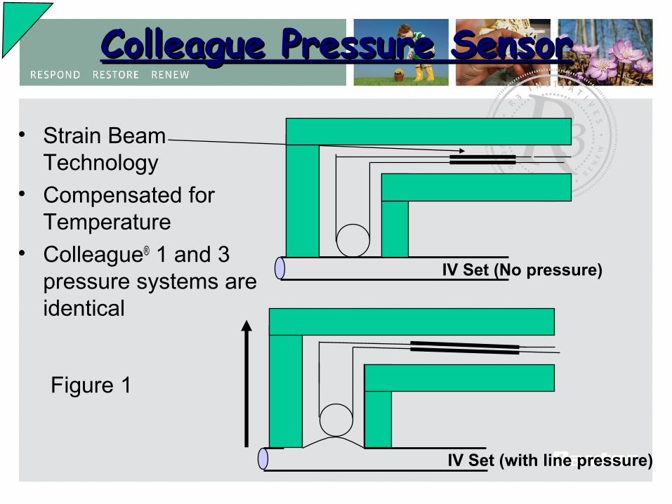
• Strain Beam Technology
• Compensated for Temperature
• Colleague® 1 and 3pressure systems areidentical
Colleague Pressure SensorColleague Pressure Sensor
IV Set (with line pressure)
Figure 1
IV Set (No pressure)
84
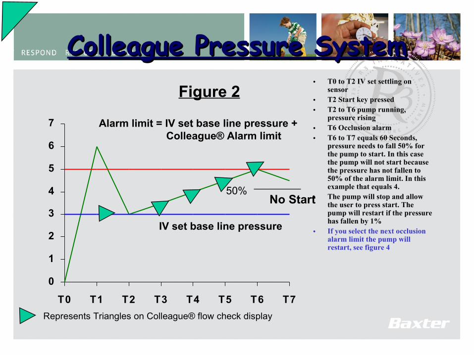
Colleague Pressure SystemColleague Pressure System• T0 to T2 IV set settling on
sensor • T2 Start key pressed• T2 to T6 pump running,
pressure rising• T6 Occlusion alarm• T6 to T7 equals 60 Seconds,
pressure needs to fall 50% for the pump to start. In this case the pump will not start because the pressure has not fallen to 50% of the alarm limit. In this example that equals 4.
• The pump will stop and allow the user to press start. The pump will restart if the pressure has fallen by 1%
• If you select the next occlusion alarm limit the pump will restart, see figure 4
0
1
2
3
4
5
6
7
T0 T1 T2 T3 T4 T5 T6 T7
IV set base line pressure
Alarm limit = IV set base line pressure + Colleague® Alarm limit
No Start
Figure 2
Represents Triangles on Colleague® flow check display
50%
85
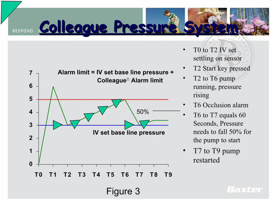
Colleague Pressure SystemColleague Pressure System• T0 to T2 IV set
settling on sensor• T2 Start key pressed• T2 to T6 pump
running, pressure rising
• T6 Occlusion alarm
• T6 to T7 equals 60 Seconds, Pressure needs to fall 50% for the pump to start
• T7 to T9 pump restarted
0
1
2
3
4
5
6
7
T0 T1 T2 T3 T4 T5 T6 T7 T8 T9
IV set base line pressure
Alarm limit = IV set base line pressure + Colleague® Alarm limit
Figure 3
50%
86
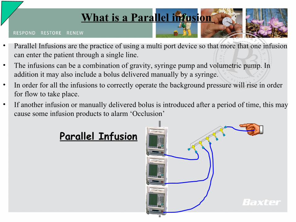
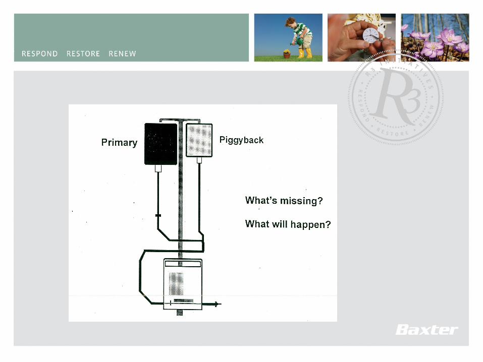
What is a Parallel infusion
• Parallel Infusions are the practice of using a multi port device so that more that one infusion can enter the patient through a single line.
• The infusions can be a combination of gravity, syringe pump and volumetric pump. In addition it may also include a bolus delivered manually by a syringe.
• In order for all the infusions to correctly operate the background pressure will rise in order for flow to take place.
• If another infusion or manually delivered bolus is introduced after a period of time, this may cause some infusion products to alarm ‘Occlusion’
Parallel Infusion
87
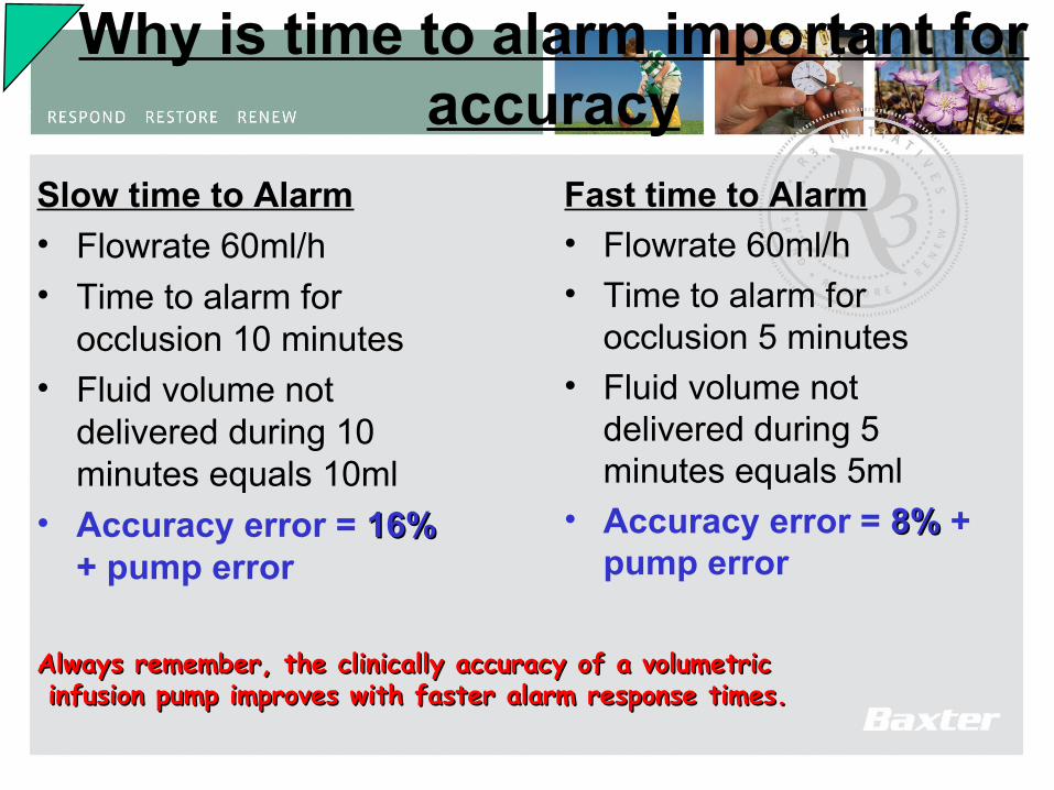
Slow time to Alarm
• Flowrate 60ml/h• Time to alarm for
occlusion 10 minutes• Fluid volume not
delivered during 10 minutes equals 10ml
• Accuracy error = 16%16% + pump error
Fast time to Alarm• Flowrate 60ml/h• Time to alarm for
occlusion 5 minutes• Fluid volume not
delivered during 5 minutes equals 5ml
• Accuracy error = 8%8% + pump error
Why is time to alarm important for accuracy
Always remember, the clinically accuracy of a volumetricAlways remember, the clinically accuracy of a volumetric infusion pump improves with faster alarm response times.infusion pump improves with faster alarm response times.

88
• “Monitoring of in line pressure is not useful for predicting or detecting infiltration of peripheral catheter sites in infants. The method lacks sensitivity, is too specific, and has poor predictive and detective ability.”
Reference : Phelps.S.J
“Inability of inline pressure monitoring to predict or detect infiltration of peripheral intravenous catheters in infants”
Clinical Pharmacy 1990
Infiltration

89
Infiltration • “Conclusion
The results indicate that the pressure transducer of the IVAC 565 is accurate at measuring in-line pressure. However, there is no conclusive evidence of predictive changes in pressure which occur prior to infiltration and the measurement of in-line ‘resistance’ clinically is not feasible”
Reference : S.Smith, M.Hall and Pairaudeau“A clinical and in vitro assessment of a variable pressure pump relating to neonatal infusions”ITCM,January / February 1991
90
Infiltration • Historically, the nurse has been the sole monitor of the catheter site; however, nurse
monitoring is usually limited to periodic visual assessments of the catheter insertion site or to assessment following an infusion device alarm. While nursing assessment remains the "gold" standard in infiltration detection, appearance of the clinical signs of infiltration (i.e., local oedema, induration, inability to get a flashback, etc.) often occur too late or are not prominent enough to prevent serious patient injury. Although several types of infusion devices with some form of infiltration monitoring ability have been marketed, there is no scientific evidence that any of the currently marketed infusion devices that use pressure to detect infiltration are capable of predicting or detecting infiltration in any patient population.
Reference : http://www.abbotthosp.com/prod/edds/CME/CME10.html18/03/99

91
• Cause of Infiltration
– 1. Dislodgement of the distal tip of the cannula into the tissues surrounding the vein.
– 2. Constriction of the blood flow distal to the cannula tip, which increases venous pressure and allows fluid to leak from the hole in the vein made by the cannula.
– 3. The nature of the drug administered. A number of cytotoxic drugs are known to lead to extravasation therapy, but other drugs which are hypertonic or that have extreme pH (Clarke 1997).

92
Effect of Infiltration
• Effect on Patient– Swelling around catheter
entry– Pain – Redness around entry– Tissue damage
93
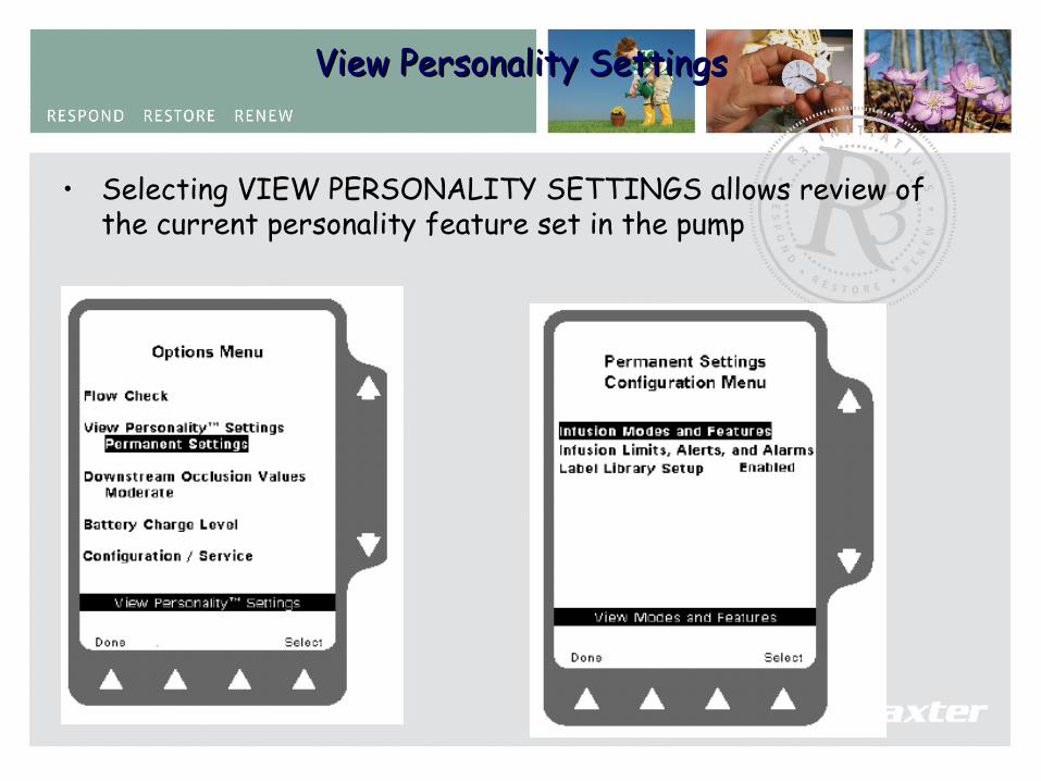
View Personality SettingsView Personality Settings
• Selecting VIEW PERSONALITY SETTINGS allows review of the current personality feature set in the pump
94
Downstream Occlusion PressureDownstream Occlusion Pressure
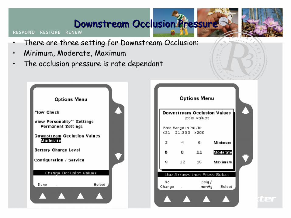
• There are three setting for Downstream Occlusion:• Minimum, Moderate, Maximum• The occlusion pressure is rate dependant

95
The Battery Charge LevelThe Battery Charge Level
• The charge of the battery can be viewed from the Options screen by selection of the Battery Charge Level.
All 10 boxes filled in meansthe battery is fully charged.
96
Configuration / ServiceConfiguration / Service
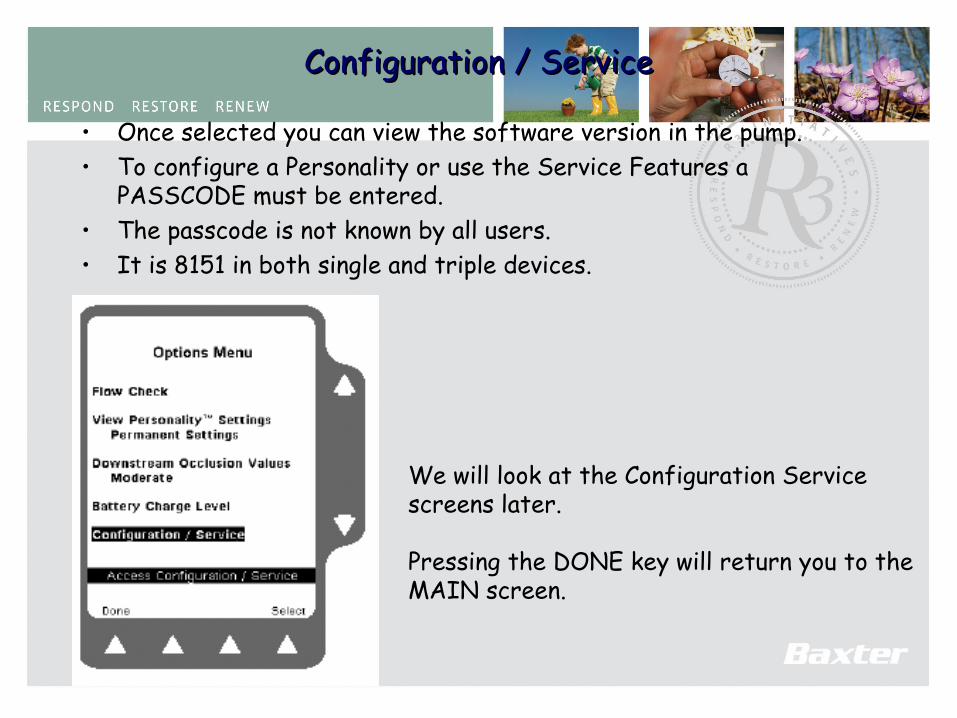
• Once selected you can view the software version in the pump.• To configure a Personality or use the Service Features a
PASSCODE must be entered.• The passcode is not known by all users.• It is 8151 in both single and triple devices.
We will look at the Configuration Service screens later.
Pressing the DONE key will return you to theMAIN screen.
97
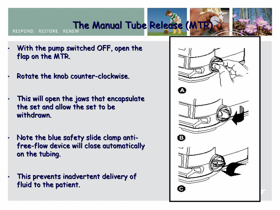
The Manual Tube Release (MTR)The Manual Tube Release (MTR)
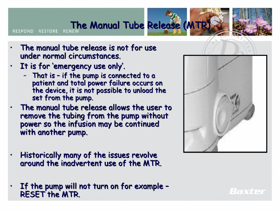
• The manual tube release is not for use The manual tube release is not for use under normal circumstances.under normal circumstances.
• It is for ‘emergency use only’.It is for ‘emergency use only’.– That is – if the pump is connected to a That is – if the pump is connected to a
patient and total power failure occurs on patient and total power failure occurs on the device, it is not possible to unload the the device, it is not possible to unload the set from the pump.set from the pump.
• The manual tube release allows the user to The manual tube release allows the user to remove the tubing from the pump without remove the tubing from the pump without power so the infusion may be continued power so the infusion may be continued with another pump.with another pump.
• Historically many of the issues revolve Historically many of the issues revolve around the inadvertent use of the MTR.around the inadvertent use of the MTR.
• If the pump will not turn on for example – If the pump will not turn on for example – RESET the MTR.RESET the MTR.
98
The Manual Tube Release (MTR)The Manual Tube Release (MTR)
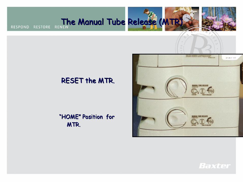
RESET the MTR.RESET the MTR.
““HOME” Position for HOME” Position for MTR.MTR.
99
The Manual Tube Release (MTR)The Manual Tube Release (MTR)
• With the pump switched OFF, open the With the pump switched OFF, open the flap on the MTR.flap on the MTR.
• Rotate the knob counter-clockwise.Rotate the knob counter-clockwise.
• This will open the jaws that encapsulate This will open the jaws that encapsulate the set and allow the set to be the set and allow the set to be withdrawn.withdrawn.
• Note the blue safety slide clamp anti-Note the blue safety slide clamp anti-free-flow device will close automatically free-flow device will close automatically on the tubing.on the tubing.
• This prevents inadvertent delivery of This prevents inadvertent delivery of fluid to the patient. fluid to the patient.
100
The Manual Tube Release (MTR)The Manual Tube Release (MTR)
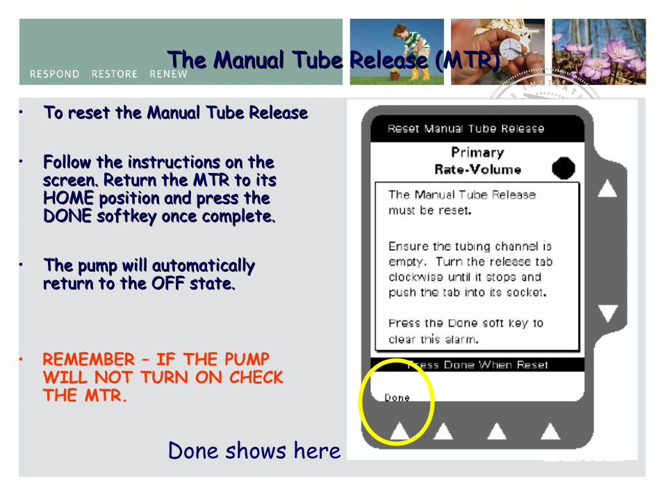
• To reset the Manual Tube ReleaseTo reset the Manual Tube Release
• Follow the instructions on the Follow the instructions on the screen. Return the MTR to its screen. Return the MTR to its HOME position and press the HOME position and press the DONE softkey once complete.DONE softkey once complete.
• The pump will automatically The pump will automatically return to the OFF state.return to the OFF state.
• REMEMBER – IF THE PUMP WILL NOT TURN ON CHECK THE MTR.
Done shows here
101
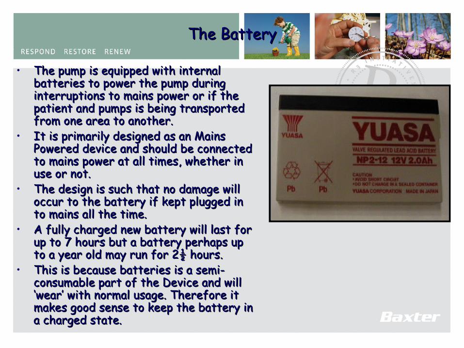
The BatteryThe Battery
• The pump is equipped with internal The pump is equipped with internal batteries to power the pump during batteries to power the pump during interruptions to mains power or if the interruptions to mains power or if the patient and pumps is being transported patient and pumps is being transported from one area to another.from one area to another.
• It is primarily designed as an Mains It is primarily designed as an Mains Powered device and should be connected Powered device and should be connected to mains power at all times, whether in to mains power at all times, whether in use or not.use or not.
• The design is such that no damage will The design is such that no damage will occur to the battery if kept plugged in occur to the battery if kept plugged in to mains all the time.to mains all the time.
• A fully charged new battery will last for A fully charged new battery will last for up to 7 hours but a battery perhaps up up to 7 hours but a battery perhaps up to a year old may run for 2½ hours.to a year old may run for 2½ hours.
• This is because batteries is a semi-This is because batteries is a semi-consumable part of the Device and will consumable part of the Device and will ‘wear’ with normal usage. Therefore it ‘wear’ with normal usage. Therefore it makes good sense to keep the battery in makes good sense to keep the battery in a charged state.a charged state.

102
The Lithium BatteryThe Lithium Battery
• The Lithium battery provides back-up for the The Lithium battery provides back-up for the volatile memory with the devicevolatile memory with the device
• While the main battery powers the infusion the While the main battery powers the infusion the Lithium battery maintains the memory in the Lithium battery maintains the memory in the device such as Pump Personalities and Event device such as Pump Personalities and Event History.History.
• It is a dual Lithium pack consisting of 2 x 3.6 It is a dual Lithium pack consisting of 2 x 3.6 volt cells.volt cells.
• Typically the life of the Lithium is 4 to 5 years, Typically the life of the Lithium is 4 to 5 years, however under certain circumstances this can however under certain circumstances this can be compromised.be compromised.
103
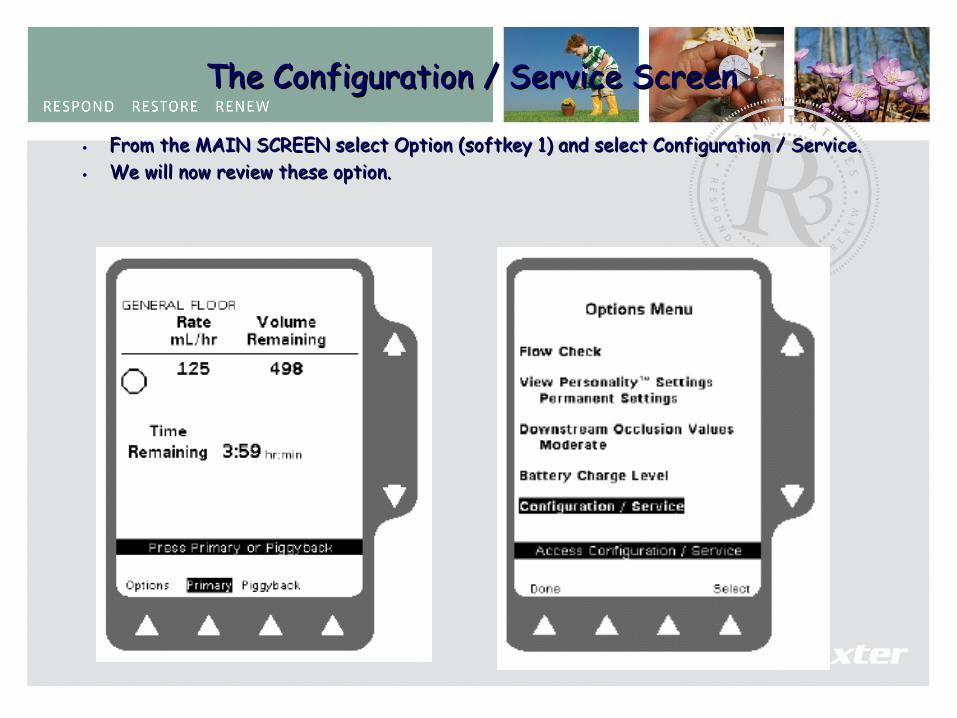
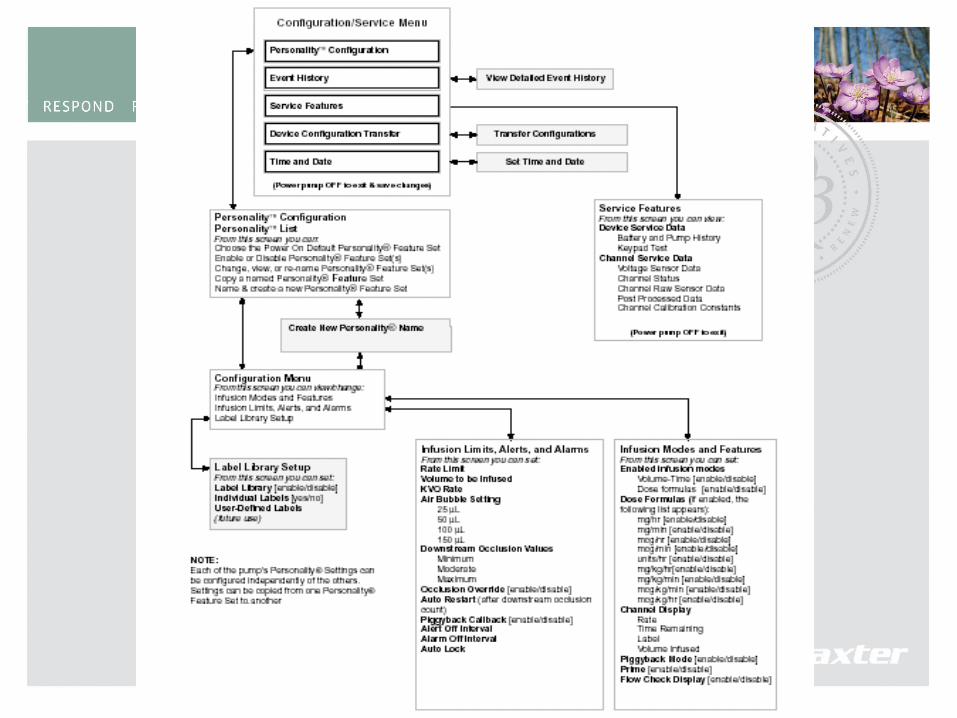
The Configuration / Service ScreenThe Configuration / Service Screen • From the MAIN SCREEN select Option (softkey 1) and select Configuration / Service. From the MAIN SCREEN select Option (softkey 1) and select Configuration / Service. • We will now review these option.We will now review these option.
104
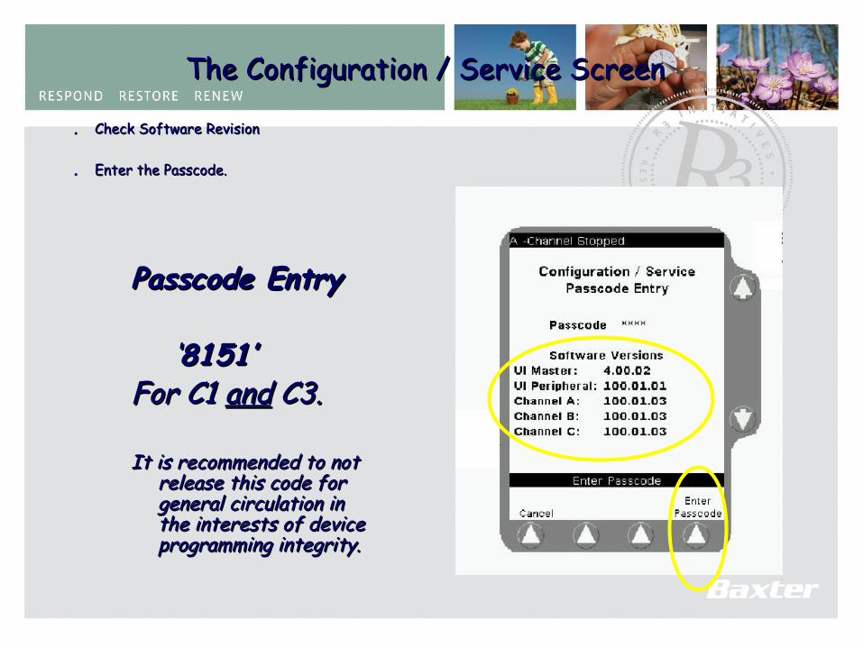
The Configuration / Service ScreenThe Configuration / Service Screen • Check Software RevisionCheck Software Revision
• Enter the Passcode.Enter the Passcode.
Passcode EntryPasscode Entry
‘‘8151’8151’For C1 For C1 andand C3. C3.
It is recommended to not It is recommended to not release this code for release this code for general circulation in general circulation in the interests of device the interests of device programming integrity.programming integrity.
105
106
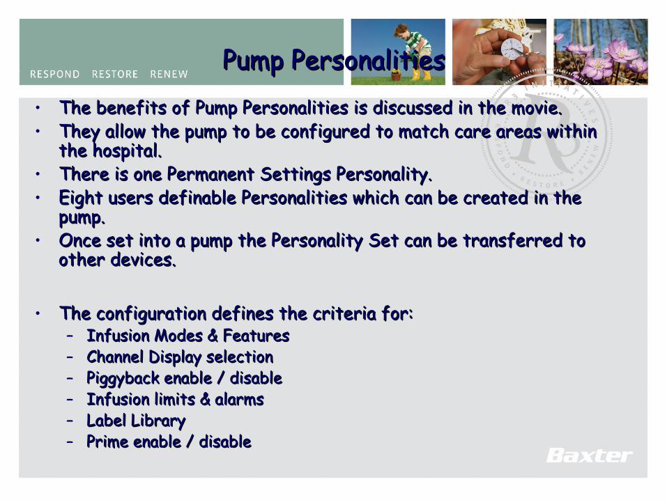
Pump PersonalitiesPump Personalities• The benefits of Pump Personalities is discussed in the movie.The benefits of Pump Personalities is discussed in the movie.• They allow the pump to be configured to match care areas within They allow the pump to be configured to match care areas within
the hospital.the hospital.• There is one Permanent Settings Personality.There is one Permanent Settings Personality.• Eight users definable Personalities which can be created in the Eight users definable Personalities which can be created in the
pump.pump.• Once set into a pump the Personality Set can be transferred to Once set into a pump the Personality Set can be transferred to
other devices.other devices.
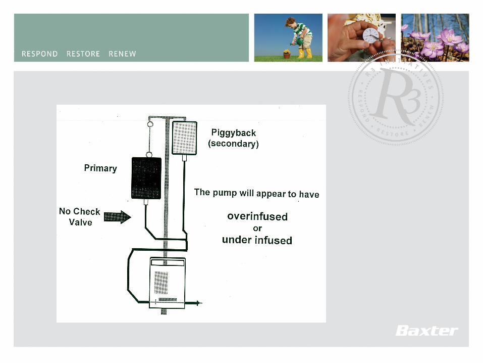
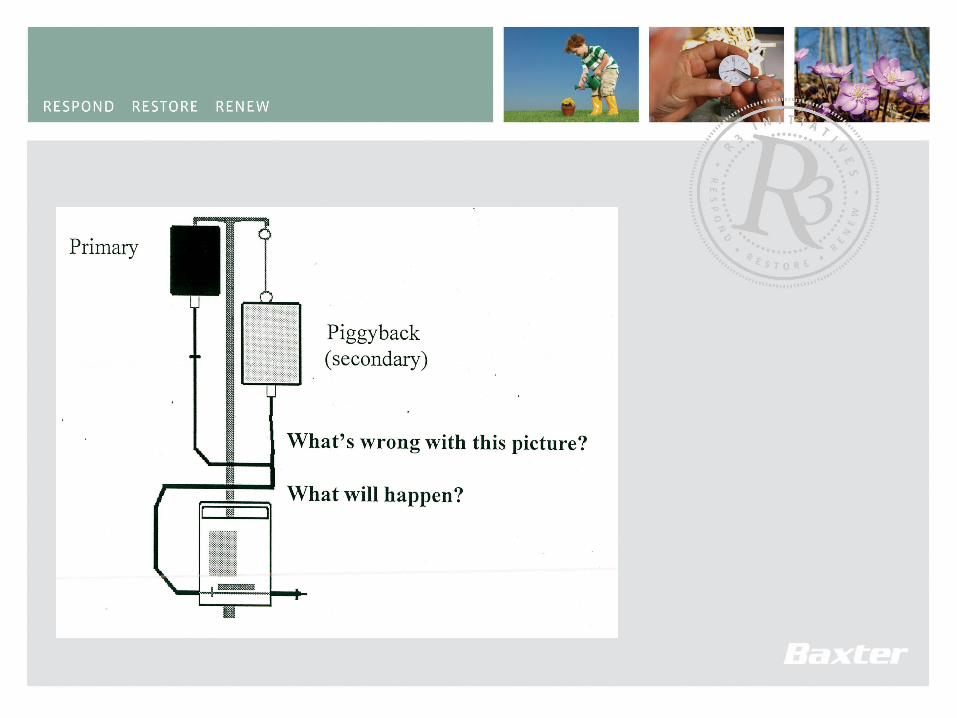
• The configuration defines the criteria for:The configuration defines the criteria for:– Infusion Modes & FeaturesInfusion Modes & Features– Channel Display selectionChannel Display selection– Piggyback enable / disablePiggyback enable / disable– Infusion limits & alarmsInfusion limits & alarms– Label LibraryLabel Library– Prime enable / disablePrime enable / disable
107
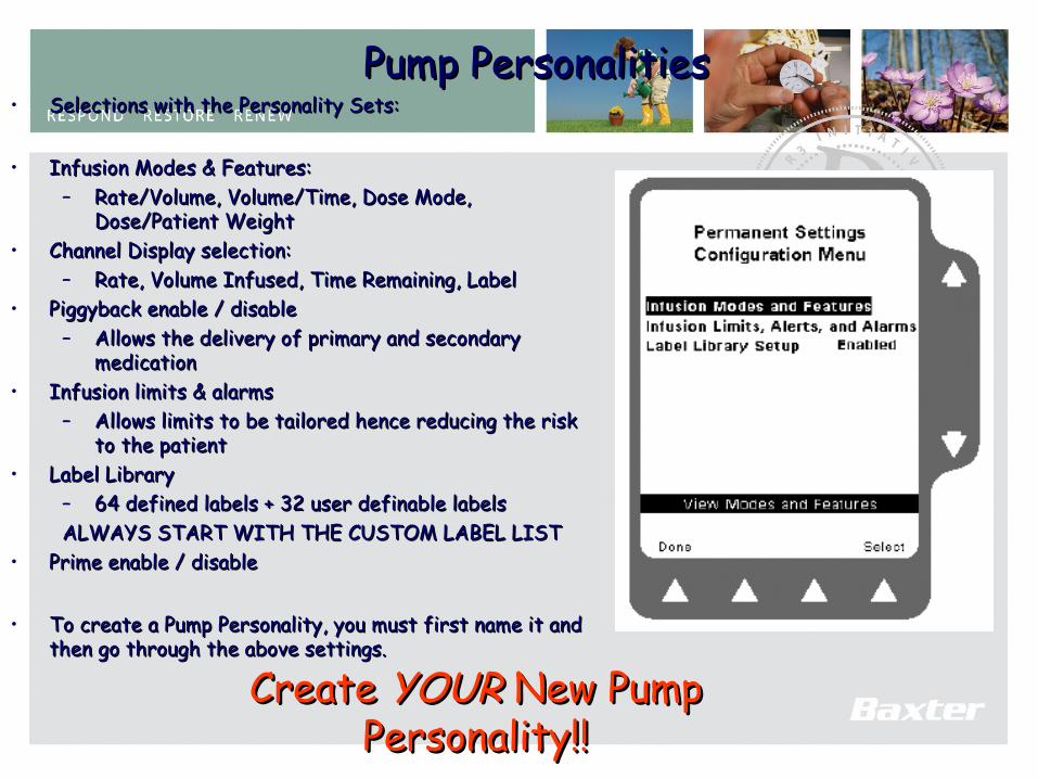
Pump PersonalitiesPump Personalities• Selections with the Personality Sets:Selections with the Personality Sets:
• Infusion Modes & Features:Infusion Modes & Features:– Rate/Volume, Volume/Time, Dose Mode, Rate/Volume, Volume/Time, Dose Mode,
Dose/Patient WeightDose/Patient Weight• Channel Display selection:Channel Display selection:
– Rate, Volume Infused, Time Remaining, LabelRate, Volume Infused, Time Remaining, Label• Piggyback enable / disablePiggyback enable / disable
– Allows the delivery of primary and secondary Allows the delivery of primary and secondary medicationmedication
• Infusion limits & alarmsInfusion limits & alarms– Allows limits to be tailored hence reducing the risk Allows limits to be tailored hence reducing the risk
to the patientto the patient• Label LibraryLabel Library
– 64 defined labels + 32 user definable labels64 defined labels + 32 user definable labelsALWAYS START WITH THE CUSTOM LABEL LISTALWAYS START WITH THE CUSTOM LABEL LIST
• Prime enable / disablePrime enable / disable
• To create a Pump Personality, you must first name it and To create a Pump Personality, you must first name it and then go through the above settings.then go through the above settings.
Create Create YOUR YOUR New Pump New Pump Personality!!Personality!!
108
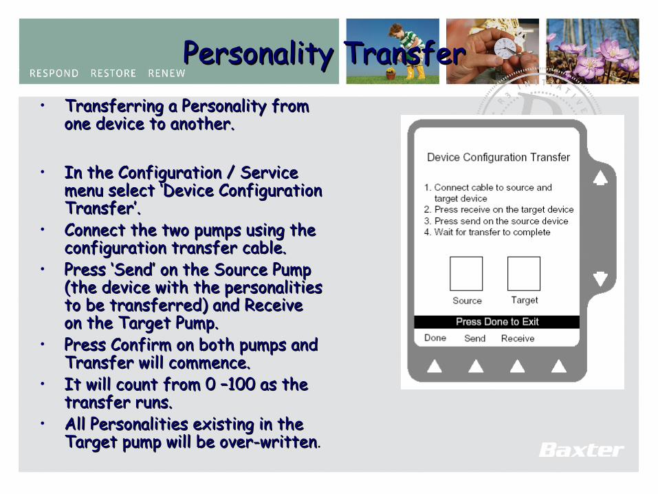
Personality TransferPersonality Transfer • Transferring a Personality from Transferring a Personality from
one device to another.one device to another.
• In the Configuration / Service In the Configuration / Service menu select ‘Device Configuration menu select ‘Device Configuration Transfer’.Transfer’.
• Connect the two pumps using the Connect the two pumps using the configuration transfer cable.configuration transfer cable.
• Press ‘Send’ on the Source Pump Press ‘Send’ on the Source Pump (the device with the personalities (the device with the personalities to be transferred) and Receive to be transferred) and Receive on the Target Pump.on the Target Pump.
• Press Confirm on both pumps and Press Confirm on both pumps and Transfer will commence.Transfer will commence.
• It will count from 0 –100 as the It will count from 0 –100 as the transfer runs. transfer runs.
• All Personalities existing in the All Personalities existing in the Target pump will be over-writtenTarget pump will be over-written.
109
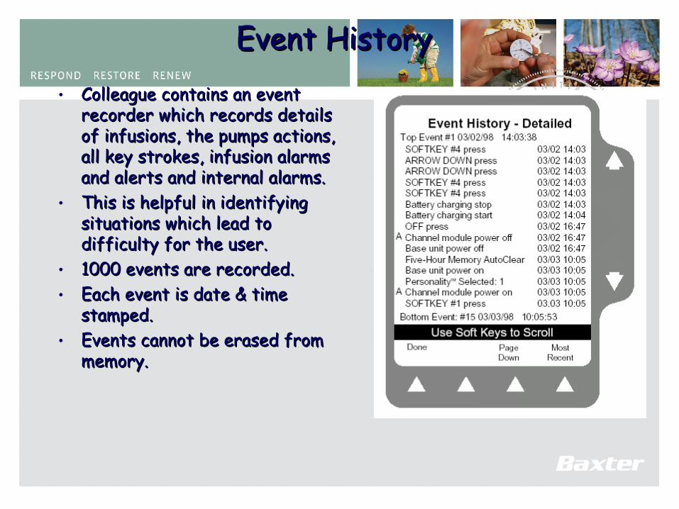
Event HistoryEvent History• Colleague contains an event Colleague contains an event
recorder which records details recorder which records details of infusions, the pumps actions, of infusions, the pumps actions, all key strokes, infusion alarms all key strokes, infusion alarms and alerts and internal alarms.and alerts and internal alarms.
• This is helpful in identifying This is helpful in identifying situations which lead to situations which lead to difficulty for the user.difficulty for the user.
• 1000 events are recorded.1000 events are recorded.• Each event is date & time Each event is date & time
stamped.stamped.• Events cannot be erased from Events cannot be erased from
memory.memory.
110
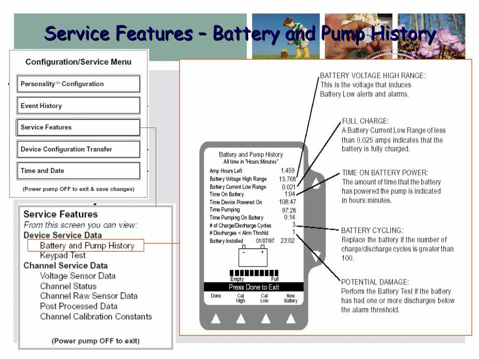
Service Features – Battery and Pump HistoryService Features – Battery and Pump History
111
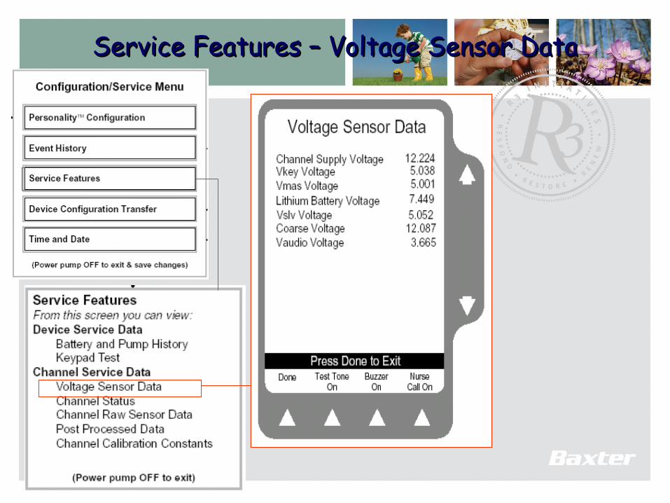
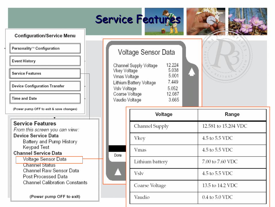
Service Features – Voltage Sensor DataService Features – Voltage Sensor Data
112
Service FeaturesService Features
113
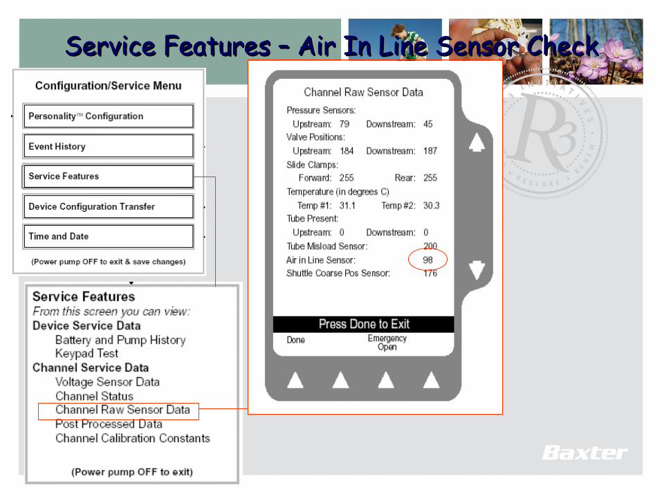
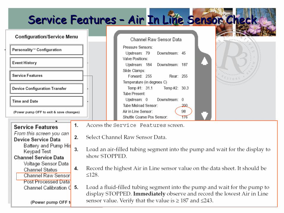
Service Features – Air In Line Sensor CheckService Features – Air In Line Sensor Check
114
Service Features – Air In Line Sensor CheckService Features – Air In Line Sensor Check
115
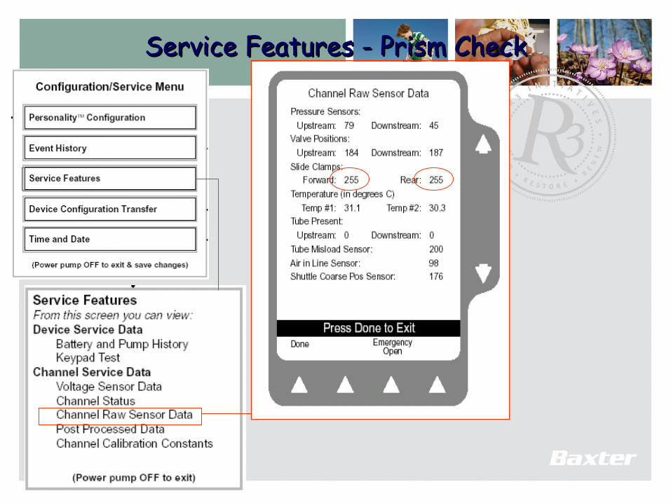
Service Features - Prism CheckService Features - Prism Check

116
Time and DateTime and Date
• Colleague does not Colleague does not automatically set automatically set Day Light Savings Day Light Savings Time.Time.
• Date and Time do Date and Time do not transfer over not transfer over
117
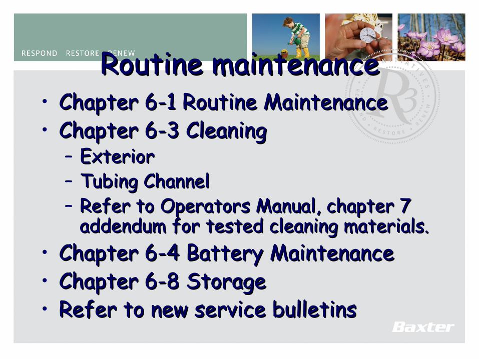
Routine maintenanceRoutine maintenance• Chapter 6-1 Routine MaintenanceChapter 6-1 Routine Maintenance• Chapter 6-3 CleaningChapter 6-3 Cleaning
– ExteriorExterior– Tubing ChannelTubing Channel– Refer to Operators Manual, chapter 7 Refer to Operators Manual, chapter 7
addendum for tested cleaning materials.addendum for tested cleaning materials.• Chapter 6-4 Battery MaintenanceChapter 6-4 Battery Maintenance• Chapter 6-8 StorageChapter 6-8 Storage• Refer to new service bulletinsRefer to new service bulletins

118
Service BulletinsService Bulletins
• Colleague “On/Off” Key cover.Colleague “On/Off” Key cover.• Preventative Maintenance.Preventative Maintenance.• Keypad Insulator.Keypad Insulator.• Battery Connector HarnessBattery Connector Harness• Technical Service Bulletins will be sent to all the Technical Service Bulletins will be sent to all the
Baxter approved Colleague Service Centers.Baxter approved Colleague Service Centers.
119
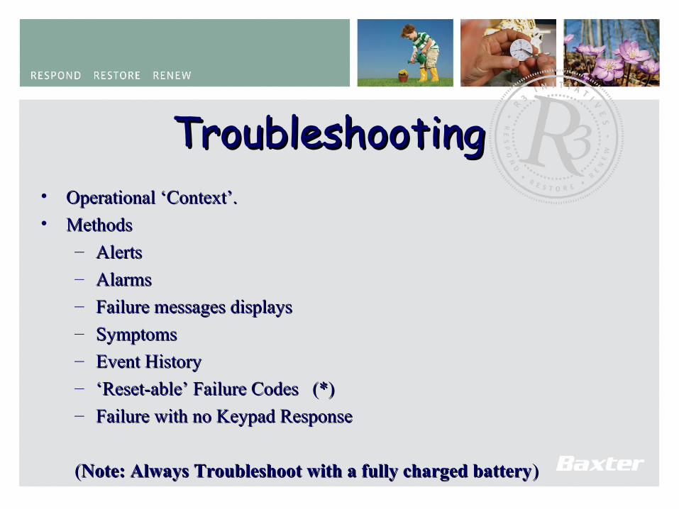
TroubleshootingTroubleshooting• Operational ‘Context’.Operational ‘Context’.
• Methods Methods
– AlertsAlerts
– AlarmsAlarms
– Failure messages displaysFailure messages displays
– SymptomsSymptoms
– Event HistoryEvent History
– ‘‘Reset-able’ Failure CodesReset-able’ Failure Codes (*)(*)
– Failure with no Keypad ResponseFailure with no Keypad Response
((Note: Always Troubleshoot with a fully charged batteryNote: Always Troubleshoot with a fully charged battery))
120
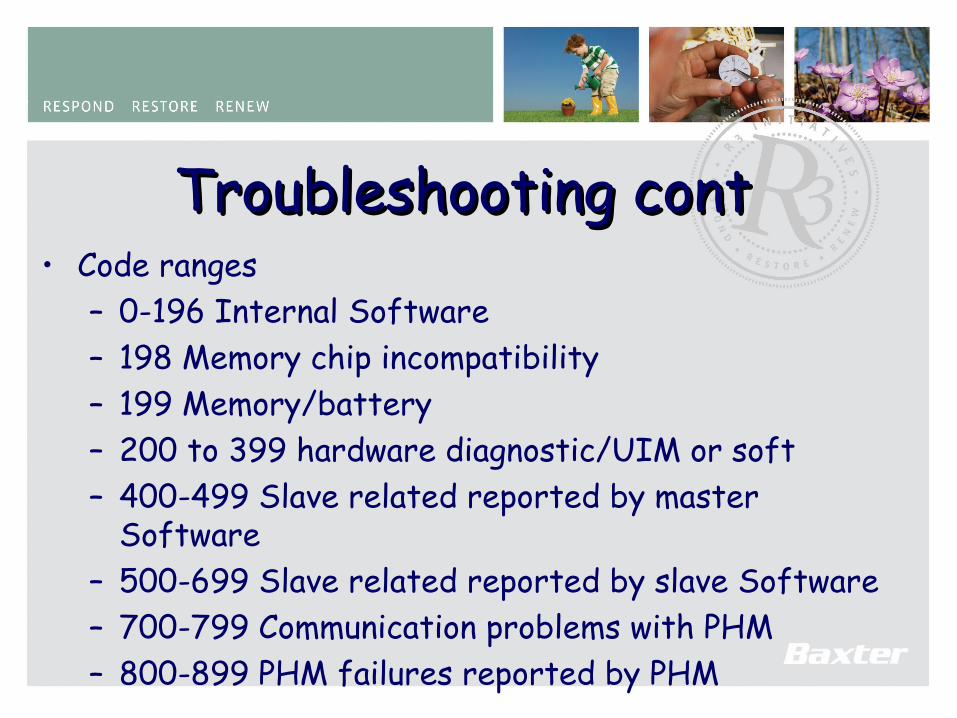
Troubleshooting contTroubleshooting cont• Code ranges
– 0-196 Internal Software– 198 Memory chip incompatibility– 199 Memory/battery– 200 to 399 hardware diagnostic/UIM or soft – 400-499 Slave related reported by master
Software– 500-699 Slave related reported by slave Software– 700-799 Communication problems with PHM– 800-899 PHM failures reported by PHM
121
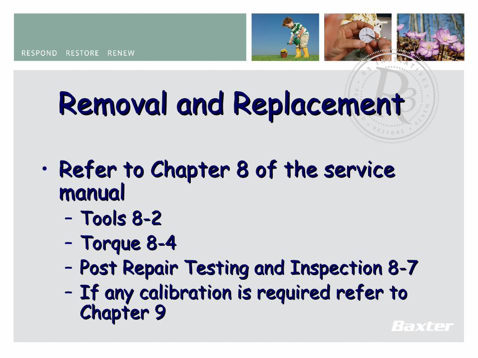
Removal and ReplacementRemoval and Replacement
• Refer to Chapter 8 of the service Refer to Chapter 8 of the service manualmanual– Tools 8-2Tools 8-2– Torque 8-4Torque 8-4– Post Repair Testing and Inspection 8-7Post Repair Testing and Inspection 8-7– If any calibration is required refer to If any calibration is required refer to
Chapter 9Chapter 9
122
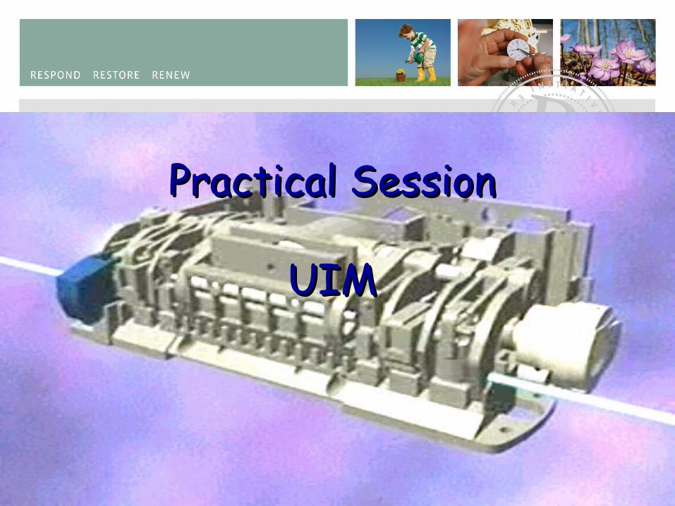
Practical SessionPractical Session
UIMUIM

123
Removal and replacement ofRemoval and replacement ofAlternate UIM LCD 8-16Alternate UIM LCD 8-16
• LCD (longer Contrast Harness required.)LCD (longer Contrast Harness required.)

124
Alternate UIM LCD cont.Alternate UIM LCD cont.
• Critical Issues Critical Issues when upgradingwhen upgrading• Wire routingWire routing• Display Display
placementplacement

125
AC Cord RetainerAC Cord Retainer8-30 part of power cord replacement8-30 part of power cord replacement..
• Slotted bottom Slotted bottom Hole to allow Hole to allow easier removal of easier removal of AC power cord.AC power cord.
• Must use screw Must use screw part number part number 4009330115 for 4009330115 for lower screw.lower screw.
126
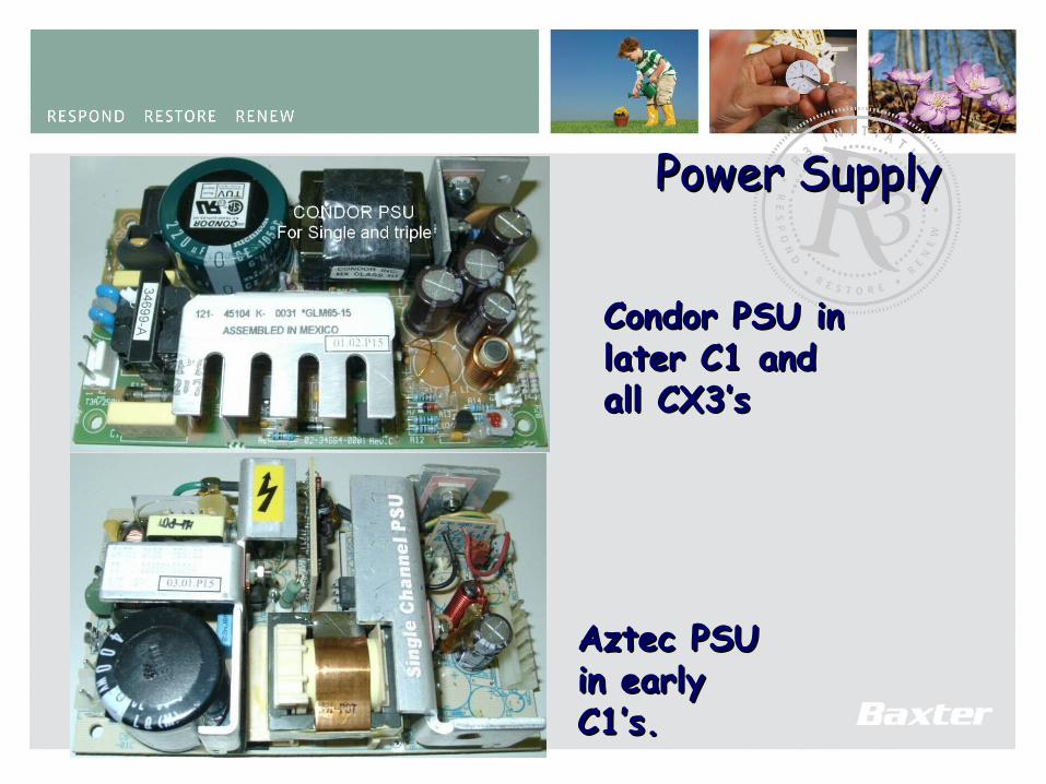
Power SupplyPower Supply
Condor PSU in Condor PSU in later C1 and later C1 and all CX3’sall CX3’s
Aztec PSU Aztec PSU in early in early C1’s.C1’s.

127
Power Supply Power Supply (cont.)(cont.)
• Aztec PSU is Obsolete.Aztec PSU is Obsolete.When upgrading from Aztec PSU, the Shield will also requiring When upgrading from Aztec PSU, the Shield will also requiring
changing .changing .
128
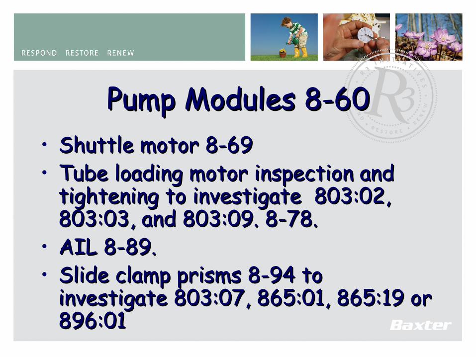
Pump Modules 8-60Pump Modules 8-60• Shuttle motor 8-69Shuttle motor 8-69• Tube loading motor inspection and Tube loading motor inspection and
tightening to investigate 803:02, tightening to investigate 803:02, 803:03, and 803:09. 8-78.803:03, and 803:09. 8-78.
• AIL 8-89.AIL 8-89.• Slide clamp prisms 8-94 to Slide clamp prisms 8-94 to
investigate 803:07, 865:01, 865:19 or investigate 803:07, 865:01, 865:19 or 896:01896:01

129
Shuttle Gear BoxShuttle Gear Box • Workshop Replacement OnlyWorkshop Replacement Only
- Cleaning.- Cleaning.- Testing Requirements- Testing Requirements- Baxter Approved Service Center.- Baxter Approved Service Center.
130
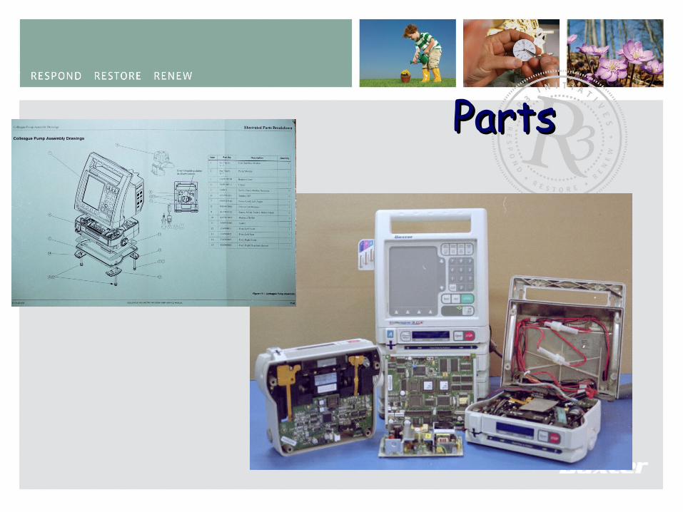
PartsParts
131
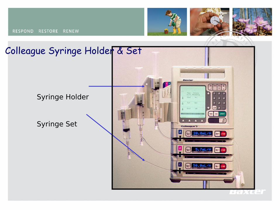
Syringe Holder
Syringe Set
Colleague Syringe Holder & Set
132
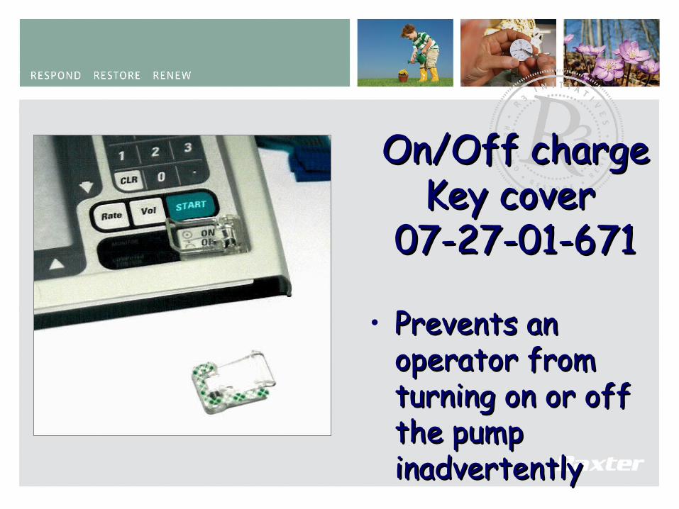
On/Off charge On/Off charge Key cover Key cover
07-27-01-67107-27-01-671
• Prevents an Prevents an operator from operator from turning on or off turning on or off the pump the pump inadvertentlyinadvertently
133
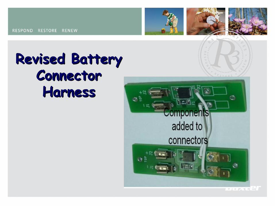
Revised Battery Revised Battery Connector Connector HarnessHarness
134
Preventive MaintenancePreventive MaintenanceDocument - 17-32-11-050Document - 17-32-11-050
• Sets the standards to accomplish an Sets the standards to accomplish an Post repair functional test and Post repair functional test and verification.verification.
• Technical Data Sheet to document Technical Data Sheet to document and record test Data for the post and record test Data for the post Repair procedure. Repair procedure.
135
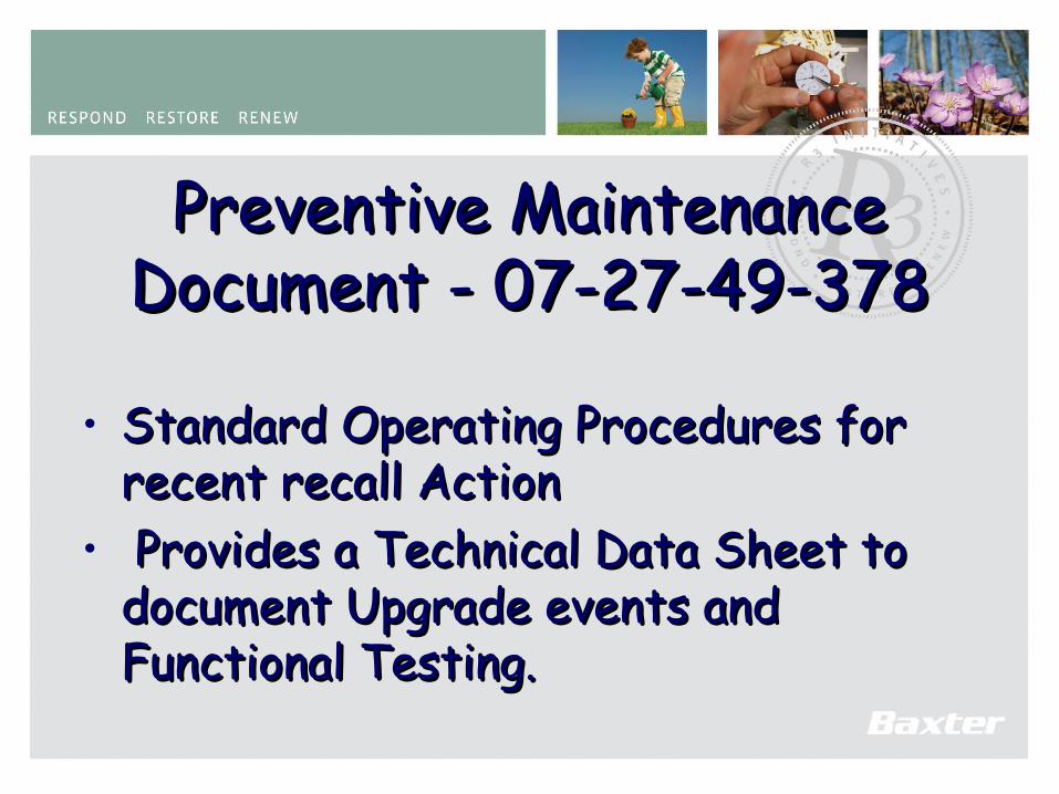
Preventive MaintenancePreventive MaintenanceDocument - 07-27-49-378Document - 07-27-49-378
• Standard Operating Procedures for Standard Operating Procedures for recent recall Actionrecent recall Action
• Provides a Technical Data Sheet to Provides a Technical Data Sheet to document Upgrade events and document Upgrade events and Functional Testing.Functional Testing.
136
Practical SessionPractical Session
Re-Assemble, Re-Assemble, Test and CheckTest and Check

137
Voltage Sensor Data Nurses Call
138
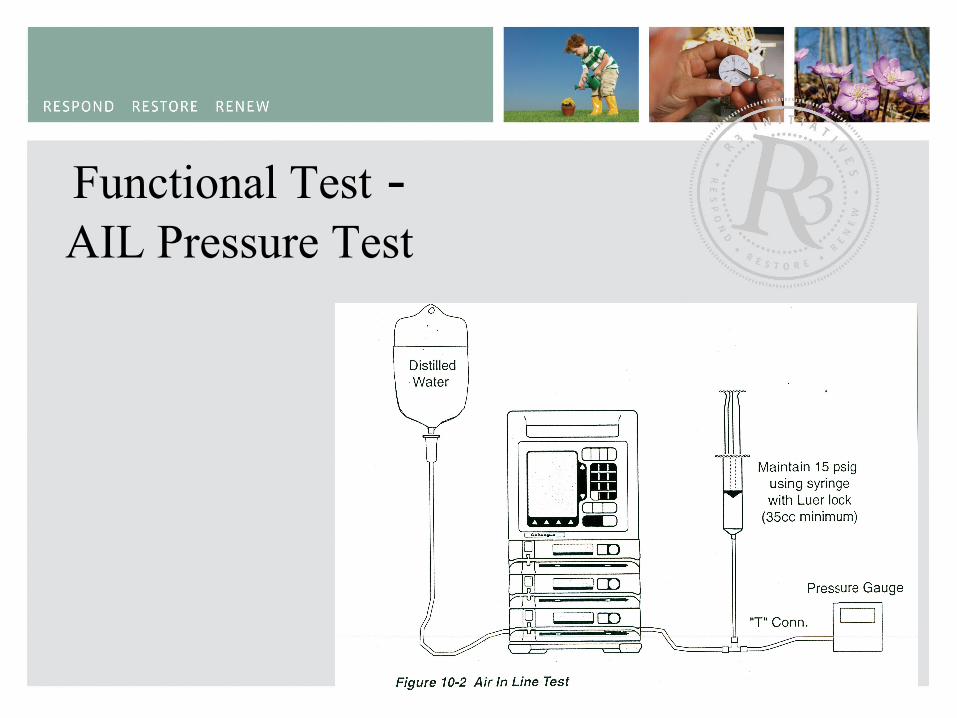
Functional Test - AIL Pressure Test
139
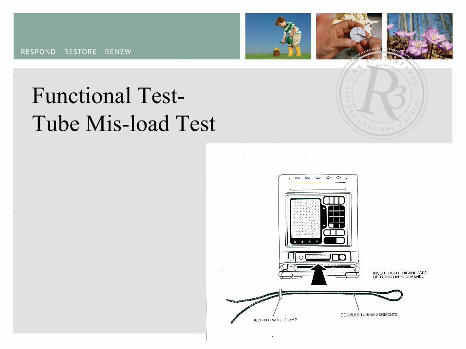
Functional Test-Tube Mis-load Test
140
Functional TestOcclusion Pressure Testing

141
Channel Raw Sensor Data
142
Channel Raw Sensor Data

143
Colleague CX 5.00 and Colleague CX 5.00 and HigherHigher
• Delay StartDelay Start• Service personnel onlyService personnel only
– Enabled or disabled via Infusion modesEnabled or disabled via Infusion modes– Used for Primary infusions onlyUsed for Primary infusions only– 24 hour format24 hour format– Operator selects through Change ModesOperator selects through Change Modes– Sets time and DateSets time and Date– A rate and volume have to be selectedA rate and volume have to be selected– Watch and Stop sign iconsWatch and Stop sign icons– Once started optionsOnce started options
144
Delay Delay StartStart
• Change modeChange mode• Primary delay startPrimary delay start• SelectSelect
145
Delay start Delay start cont.cont.
• Set or verify Set or verify correct time in correct time in 24hr format24hr format
• Volume history Volume history will be clearedwill be cleared
• Soft key setSoft key set• Press donePress done
146
Delay start Delay start cont.cont.
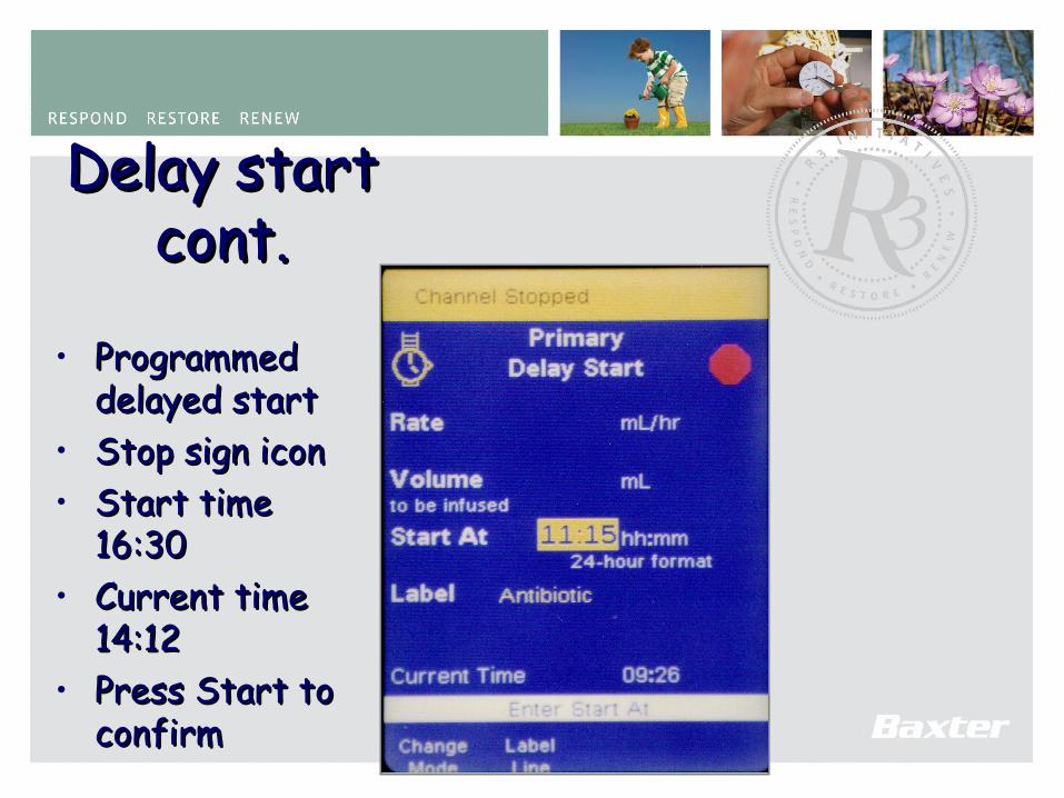
• Programmed Programmed delayed startdelayed start
• Stop sign iconStop sign icon• Start time Start time
16:3016:30• Current time Current time
14:1214:12• Press Start to Press Start to
confirmconfirm
147
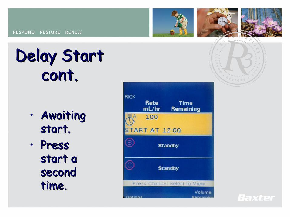
Delay Start Delay Start cont.cont.
• Awaiting Awaiting start. start.
• Press Press start a start a second second time.time.

148
Guardian InstallationGuardian Installation
• Refer to Installation Guide.Refer to Installation Guide.• Error code #198 after replacing software Error code #198 after replacing software
at next Power-On.at next Power-On.• Verification after installation of the Verification after installation of the
Guardian software Guardian software • Global Guardian Software Version 5.04Global Guardian Software Version 5.04

149
Guardian FeaturesGuardian Features
• Authorized personnel configure limitsAuthorized personnel configure limits• Authorized personnel enable or Authorized personnel enable or
disable labels independently, for each disable labels independently, for each personalitypersonality
• Can be overridden if error found or Can be overridden if error found or therapy dictates.therapy dictates.
• Available for Primary infusion onlyAvailable for Primary infusion only• Mortar and Pestle iconMortar and Pestle icon
150
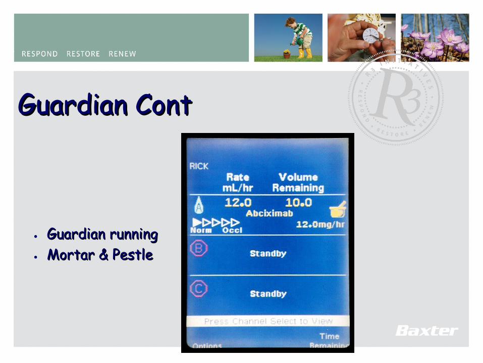
Guardian ContGuardian Cont
• Guardian runningGuardian running• Mortar & PestleMortar & Pestle
151
Guardian cont.Guardian cont.
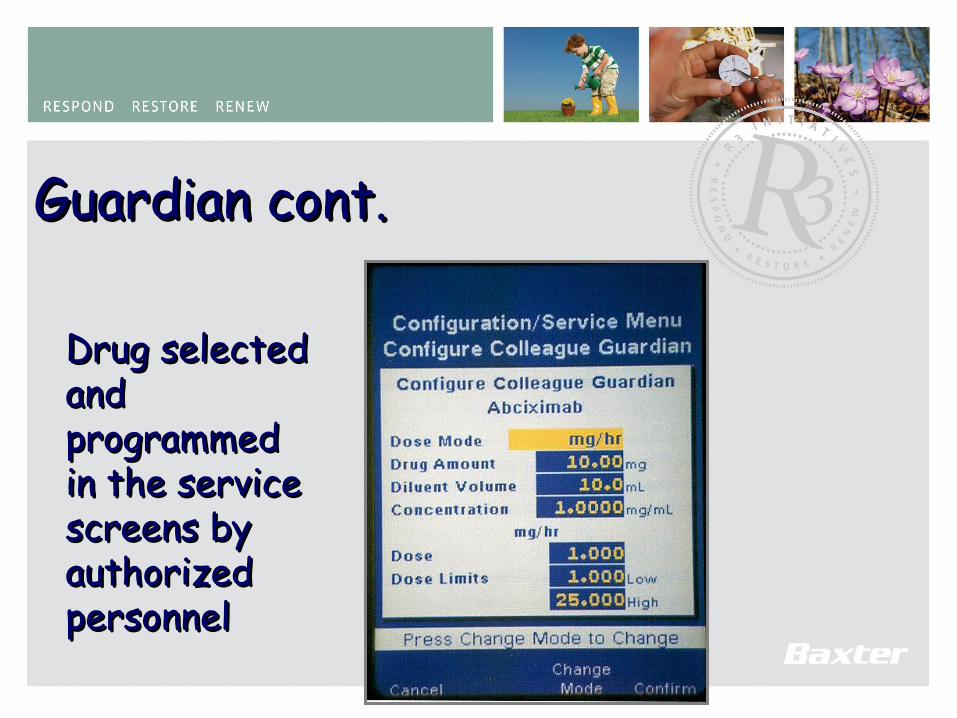
Drug selected Drug selected and and programmed programmed in the service in the service screens by screens by authorized authorized personnelpersonnel
152
Guardian Guardian cont.cont.
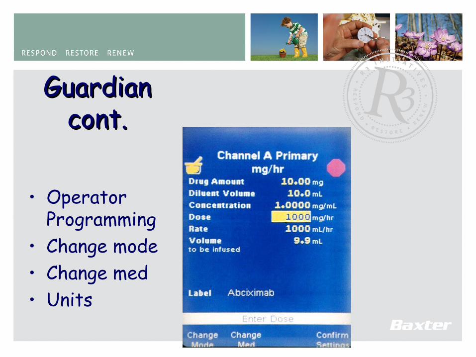
• Operator Programming
• Change mode• Change med• Units

153
Guardian limit Guardian limit warningwarning
• Can be Can be overriddenoverridden
154
Guardian Guardian cont.cont.
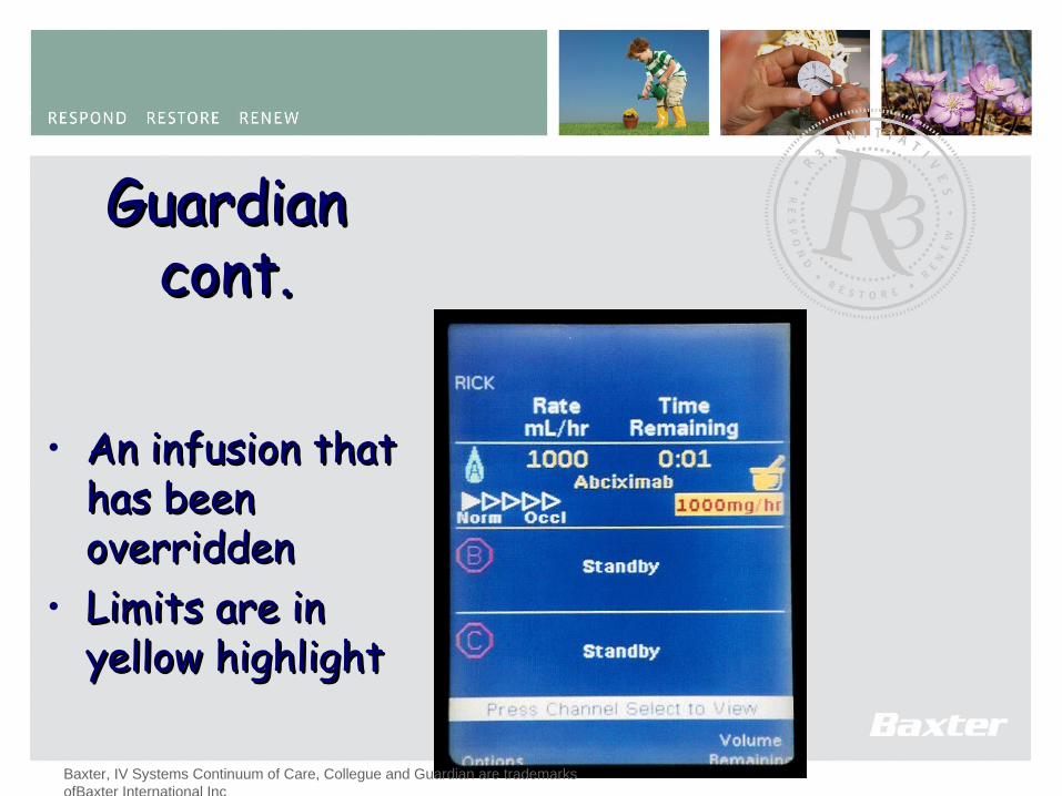
• An infusion that An infusion that has been has been overriddenoverridden
• Limits are in Limits are in yellow highlightyellow highlight
Baxter, IV Systems Continuum of Care, Collegue and Guardian are trademarks ofBaxter International Inc
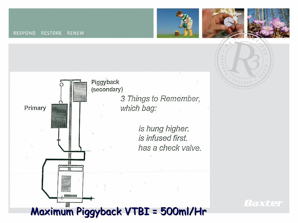
155Maximum Piggyback VTBI = 500ml/HrMaximum Piggyback VTBI = 500ml/Hr
156
157
158

159
This is the End of theColleague Technical Information
Presentation
•Complete your Practical SessionComplete your Practical Session
•Do your TestDo your Test
•Complete a Course feedback Complete a Course feedback QuestionnaireQuestionnaire
160
Congratulations!Congratulations!You have completed the Technical You have completed the Technical
Training for theTraining for the
ColleagueColleague Infusion Device Infusion Device