Embed Size (px)
Citation preview
NOTE ON COLD-JUNCTION CORRECTIONS FORTHERMOCOUPLES
By Paul D. Foote
Ordinarily, in the laboratory use of thermocouples, the cold
junction is kept at a standard reference temperature such as the
melting point of ice, while the hot junction is placed within the
furnace or substance the temperature of which is desired. How-ever, for technical purposes and general commercial use, it is not
always convenient to have an ice box at hand. For this reason
it is desirable to work with the cold junction at the temperature
of the room. This necessitates a knowledge of the corrections to
apply to the indicator readings, provided that the standardization
of the pyrometer were carried out with the cold junction at sometemperature other than that used in the technical works. Theimportance of these corrections is realized when one considers the
large range of the cold-junction temperature which in practice
frequently varies from 10 to ioo° C.
In order to obtain the temperature corresponding to any value
of the emf observed when the cold junction is at a temperature
t ° C from the relation e=f (t) computed on the basis that the cold
junction is at o° C, it is only necessary to add to the observed emf
the value of the emf developed when the cold junction is at o° Cand the hot junction is t ° C,a number which is independent of the
temperature of the furnace. However, many pyrometer gal-
vanometers are calibrated to read temperature directly and have
no scale of emf recorded. One must then express the correction
in terms of degrees, and this quantity for any given value of the
cold junction will depend, of course, upon the temperature of the
hot junction for the reason that in general the relation between
temperature and emf is not linear. A table, accordingly, might
be prepared stating the corrections to be applied to the tempera-
ture observations for all values of the hot-junction temperature
and all variations in the temperature of the cold junction.
553
554 Bulletin of the Bureau of Standads IV0I.9
The usual method of obtaining the cold-junction correction
consists in multiplying the value of the cold-junction temperature
by certain empirical factors. R. Vogel l computed these factors
for a Heraeus (Pt, ooPt-ioRh) couple having a cold junction of
50 C. Offerhaus and Fischer 2 have calculated the factors for
several types of couples.
This method of correction for cold-junction temperatures maybe derived in the following manner
:
Derivation of the Slope Correction.—L,et e and t be the observed
emf and corresponding temperature when the cold junction = o° C.
e 1 and ^=the observed emf and temperature when the cold
junction = U° C.
For any thermocouple e=f(t) (1)
then for any value ex <?i
=/(*i) (2)
But e = e1+e where e =f(Q = emf developed
when the hot junction = t ° and the cold junction = o°C.
Substituting in (1) e1+e = f(t) (3)
From (3) i = cp (ex + eQ)
From (2) tt= cp (e
t )
Denote by p the correction to add to the observed temperature
when this value is read from the plot of a couple calibrated with
its cold junction = o° C.
p = t-tl= cp(e
l +eo)-cp(el )
e 2
= cp(e1)+e (p'(e
1)+ 1-<p"(e1)+ . . . -pfo)
=e 9>'te) provided eQ and t are small in comparison
with e1and t±
hence p = —rp;cp' fe) cp{e )
dtt
<p{e ) <p(e ) dex
(de\
deo a\ _ \dt/o
dt dex
°~(de\ °approximately.
1 R. Vogel: Zs. f. Anorg Chein., p. 45; 1905.
2 Cornells Offerhaus and E. H. Fischer: Electrochem. and Metal. Ind., Sept., p. 362-364; 1908.
Foote] Cold-Junction Corrections for Thermocouples 555
This equation therefore states that in order to obtain the true
temperature (t), it is necessary to add to the observed tempera-
ture (0, the quantity obtained by multiplying the temperature
of the cold junction (t ) by the ratio of the slopes of the calibra-
tion curve at the origin and at the temperature (tt ) . The deriva-
/de\ etive
( j7 ) is but approximately equal to the quantity —j~ and
becomes less so, the farther t departs from zero. As seen from
Fig. i ,,° v is more exactly the mean slope of the calibration curve
<p\e )
from o to t ° C. Using this value the single term slope correction
becomes
:
(de\
\dtJo-to4
P =
WjThe mean slope from o to t may be determined accurately enough
by assuming some value of to in the neighborhood of the actual
value of the cold-junction temperature such as 30 C, and com-
puting the mean slope from o° to this point, i. e., the value of the
emf observed when the cold junction is at o° and the hot junction
30 divided by 30. This form of the cold-junction correction
requires but a single measurement of the emf at room tempera-
ture, whereas the usual form of correction practically necessitates
a knowledge of the curve at several points in order to evaluate the
slope ato°C. The three forms of the cold-j unction temperature
correction may be summarized thus
:
Form I p=e cp'{e,) +|Vfe) + ^Vfe) + • -
/de\
Form II P=J^ho\dt\
Form III P=j^^%\dt\
556 Bulletin of the Bureau of Standards {Vol. 9
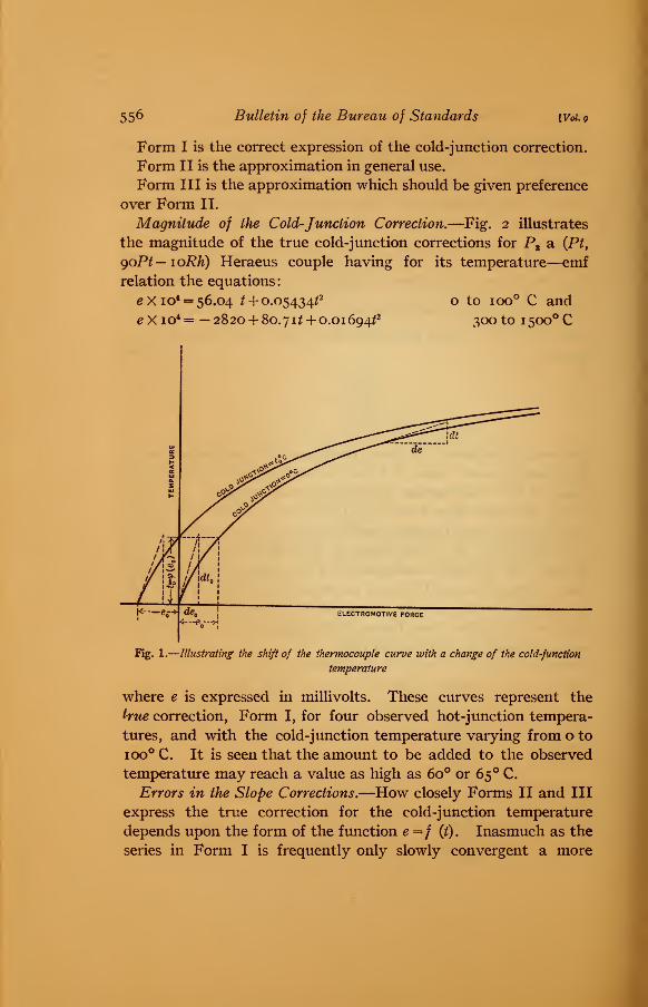
Form I is the correct expression of the cold-junction correction.
Form II is the approximation in general use.
Form III is the approximation which should be given preference
over Form II.
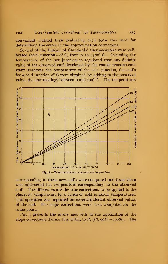
Magnitude of the Cold-Junction Correction.—Fig. 2 illustrates
the magnitude of the true cold-junction corrections for PB a (Pt,
goPt—ioRh) Heraeus couple having for its temperature—emfrelation the equations:
e X io4 = 56.04 t + 0.05434/2
eXio4 = — 2820 + 80.712 + 0.01694^
o to ioo° C and
300 to 1 500 C
Fig. 1.
—
Illustrating the shift of the thermocouple curve with a change of the cold-function
temperature
where e is expressed in millivolts. These curves represent the
true correction, Form I, for four observed hot-junction tempera-
tures, and with the cold-junction temperature varying from o to
ioo° C. It is seen that the amount to be added to the observed
temperature may reach a value as high as 6o° or 65 ° C.
Errors in the Slope Corrections.—How closely Forms II and III
express the true correction for the cold-junction temperature
depends upon the form of the function e =/ (t). Inasmuch as the
series in Form I is frequently only slowly convergent a more
Foote] Cold-Junction Corrections for Thermocouples 557
convenient method than evaluating each term was used for
determining the errors in the approximation corrections.
Several of the Bureau of Standards' thermocouples were cali-
brated (cold junction = o° C) from o to 1500 C. Assuming the
temperature of the hot junction so regulated that any definite
value of the observed emf developed by the couple remains con-
stant whatever the temperature of the cold junction, the emf's
for a cold junction o° C were obtained by adding to the observed
value, the emf readings between o and ioo° C. The temperatures
.«70
Ulcc
<60OEHiQ.
5ui
>-50Qu>ECUJ
O
§30<
§ 20
UJ
l10
H
zAx
p3 /£V-
i>
sA^v-s*
X'&&^4&
¥*
XIf V^
400 gPOz
800 3
1100OI
1400 u.oUJBB
CCUlCL
Ui
houi
>Ui
30 40 50 60 70
TEMPERATURE OF COLD JUNCTION °C
80 90
Fig. 2.
—
True correction if. cold-junction temperature
corresponding to these new emf's were computed and from them
was subtracted the temperature corresponding to the observed
emf. The differences are the true corrections to be applied to the
observed temperature for a series of cold-junction temperatures.
This operation was repeated for several different observed values
of the emf. The slope corrections were then computed for the
same points.
Fig. 3 presents the errors met with in the application of the
slope corrections, Forms II and III, to P3 (Pt, goPt-ioRh). The
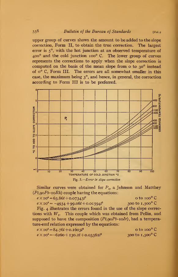
558 Bulletin oj the Bureau of Standards [Vol. 9
upper group of curves shows the amount to be added to the slope
correction, Form II, to obtain the true correction. The largest
error is 5 , with the hot junction at an observed temperature of
400 and the cold junction ioo° C. The lower group of curves
represents the corrections to apply when the slope correction is
computed on the basis of the mean slope from o to 30 instead
of o° C, Form III. The errors are all somewhat smaller in this
case, the maximum being 3 , and hence, in general, the correction
according to Form III is to be preferred.
10 20 30 40 50 60 70 80 90 100
TEMPERATURE OF COLD JUNCTION °C
Fig. 3.
—
Error in slope correction
Similar curves were obtained for P4 , a Johnson and Matthey
(Pt,goPt-ioRh) couple having the equations
:
e?Xio4 = 63.862 + 0.0734322 o to ioo° C
e X io4 = -4934 + 99.062 + 0.0 1 5942* 300 to 1 ,500° CFig. 4 illustrates the errors found in the use of the slope correc-
tions with W7 . This couple which was obtained from Pellin, and
supposed to have the composition {Pt,goPt-ioIr)yhad a tempera-
ture-emf relation expressed by the equations
:
ex io4 = 84.762 +0.160322 oto ioo°C
ex io4 =-6260 + 130.22 + 0.0338122 300 to 1,500° C
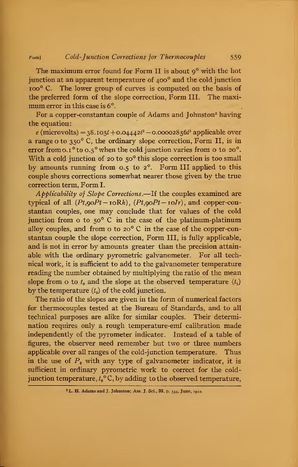
Foote] Cold-Junction Corrections for Thermocouples 559
The maximum error found for Form II is about 9 with the hot
junction at an apparent temperature of 400 and the cold junction
ioo° C. The lower group of curves is computed on the basis of
the preferred form of the slope correction, Form III. The maxi-
mum error in this case is 6°.
For a copper-constantan couple of Adams and Johnston3 having
the equation:
e (microvolts) =38.105^ + 0.04442^ —0.00002856^ applicable over
a range o to 350 C, the ordinary slope correction, Form II, is in
error fromo.i°to 0.5 ° when the cold junction varies from o to 20 .
With a cold junction of 20 to 50 this slope correction is too small
by amounts running from 0.5 to 2 . Form III applied to this
couple shows corrections somewhat nearer those given by the true
correction term, Form I.
Applicability of Slope Corrections.—If the couples examined are
typical of all (Pt}goPt — ioRh), (Pt,goPt — ioIr)
yand copper-con-
stantan couples, one may conclude that for values of the cold
junction from o to 50 C in the case of the platinum-platinum
alloy couples, and from o to 20 C in the case of the copper-con-
stantan couple the slope correction, Form III, is fully applicable,
and is not in error by amounts greater than the precision attain-
able with the ordinary pyrometric galvanometer. For all tech-
nical work, it is sufficient to add to the galvanometer temperature
reading the number obtained by multiplying the ratio of the meanslope from o to t and the slope at the observed temperature (Oby the temperature (t ) of the cold junction.
The ratio of the slopes are given in the form of numerical factors
for thermocouples tested at the Bureau of Standards, and to all
technical purposes are alike for similar couples. Their determi-
nation requires only a rough temperature-emf calibration madeindependently of the pyrometer indicator. Instead of a table of
figures, the observer need remember but two or three numbers
applicable over all ranges of the cold-j unction temperature. Thusin the use of P3 with any type of galvanometer indicator, it is
sufficient in ordinary pyrometric work to correct for the cold-
junction temperature, t ° C, by adding to the observed temperature,
3 L. H. Adams and J. Johnston; Am. J. Sci., 33, p. 534, June, 1912.
560 Bulletin of the Bureau of Standards [Vol.9
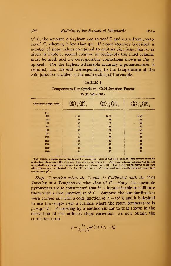
t±° C, the amount 0.6 t from 400 to 700 C and 0.5 t from 700 to
1400 C, where t is less than 50. If closer accuracy is desired, a
number of slope values computed to another significant figure, as
given in Table 1, second column, or preferably the third column,
must be used, and the corresponding corrections shown in Fig. 3
applied. For the highest attainable accuracy a potentiometer is
required, and the emf corresponding to the temperature of the
cold junction is added to the emf reading of the couple.
TABLE 1
Temperature Centigrade vs. Cold-Junction Factor
P3 (Pt, 90Pt-10Rh)
Observed temperature (M)M /de\ ^ /de\\dtJ 2M0 \dtJ 2
oC400 0.59 0.61 0.63
500 .57 .59 .61
600 .55 .57 .59
700 .53 .55 .57
800 .52 .54 .56
900 .50 .52 .54
1000 .49 .50 .52
1100 .48 .49 .51
1200 .46 .47 .49
1300 .45 .46 .48
1400 .44 .45 .47
The second column shows the factor by which the value of the cold-junction temperature must be
multiplied when using the old-type slope correction, Form II. The third column contains the factors
computed from the preferred form of the slope correction, Form III. The fourth column shows the factors
when the couple is calibrated with the cold junction at 30 C and used with a cold-junction temperature
not far from 40 ° C.
Slope Correction when the Couple is Calibrated with the Cold
Junction at a Temperature other than o° C.—Many thermocouple
pyrometers are so constructed that it is impracticable to calibrate
them with a cold junction at o° C. Suppose the standardization
were carried out with a cold junction of t t= 30° C and it is desired
to use the couple near a furnace where the room temperature is
2t=40° C. Proceeding by a method similar to that shown in the
derivation of the ordinary slope correction, we now obtain the
correction term:
P-2t !&<
9>'fe) (2*0-1*0)
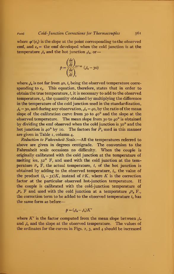
Foote] Cold-Junction Corrections for Thermocouples 561
where <p'(e2) is the slope at the point corresponding to the observed
emf, and eQ= the emf developed when the cold junction is at the
temperature ^ and the hot junction 2t , or
—
where 2t is not far from 40, t2 being the observed temperature corre-
sponding to e2 . This equation, therefore, states that in order to
obtain the true temperature, t, it is necessary to add to the observed
temperature, t2 , the quantity obtained by multiplying the difference
in the temperature of the cold junction used in the standardization,
i*o= 3°> and during any observation, 2t
= 40, by the ratio of the meanslope of the calibration curve from 30 to 40 and the slope at the
observed temperature. The mean slope from 30 to 40 is obtained
by dividing the emf observed when the cold junction is 30 and the
hot junction is 40 by 10. The factors for P3 used in this mannerare given in Table 1 , column 4.
Reduction to Fahrenheit Scale.—All the temperatures referred to
above are given in degrees centigrade. The conversion to the
Fahrenheit scale occasions no difficulty. When the couple is
originally calibrated with the cold junction at the temperature of
melting ice, 32 ° F, and used with the cold junction at the tem-
perature t° F, the actual temperature, t, of the hot junction is
obtained by adding to the observed temperature, tu the value of
the product (^-32)^, instead of t'K, where K is the correction
factor at the particular observed hot-junction temperature. If
the couple is calibrated with the cold-junction temperature of
yt°o F and used with the cold junction at a temperature 2t° F.,
the correction term to be added to the observed temperature t2 has
the same form as before
—
where K' is the factor computed from the mean slope between XUand 2t and the slope at the observed temperature. The values of
the ordinates for the curves in Figs. 2,3, and 4 should be increased
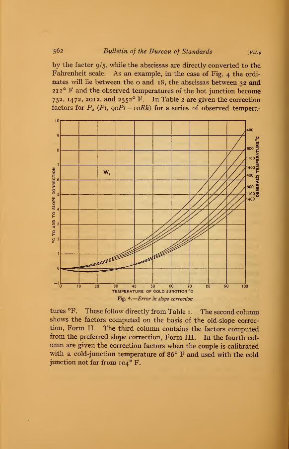
562 Bulletin of the Bureau of Standards [V0I.9
by the factor 9/5, while the abscissas are directly converted to the
Fahrenheit scale. As an example, in the case of Fig. 4 the ordi-
nates will lie between the o and 18, the abscissas between 32 and212 F and the observed temperatures of the hot junction become
752, 1472, 2012, and 2552 F. In Table 2 are given the correction
factors for P3 (Pt, goPt - loRh) for a series of observed tempera-
10 0040 50 60 70
TEMPERATURE OF COLD JUNCTION °C
Fig. 4.
—
Error in slope correction
tures °F. These follow directly from Table 1 . The second columnshows the factors computed on the basis of the old-slope correc-
tion, Form II. The third column contains the factors computedfrom the preferred slope correction, Form III. In the fourth col-
umn are given the correction factors when the couple is calibrated
with a cold-junction temperature of 86° F and used with the cold
junction not far from 104 F.
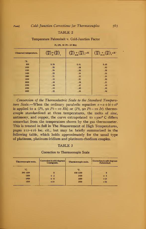
Foote] Cold-Junction Corrections for Thermocouples
TABLE 2
Temperature Fahrenheit v. Cold-Junction Factor
P3 (Pt, 90 Pt-10 Rh)
563
Observed temperature. (£):(£), (aO^CaDr* (<"/ BM04W 2 ^
°F.
800 0.59 0.61 0.63
1000 .56 .58 .60
1200 .54 .56 .58
1400 .53 .54 .56
1600 .51 .52 . .54
1800 .49 .51 .53
2000 .48 .49 .51
2200 .46 .47 .49
2400 .44 .45 .48
2600 .43 .44 .46
Conversion of the Thermoelectric Scale to the Standard Tempera-
ture Scale.—When the ordinary parabolic equation e = a + bt + ct2
is applied to a (Pt, 90 Pt- 10 Rh) or (Pt, 90 Pt- 10 Ir) thermo-
couple standardized at three temperatures, the melts of zinc,
antimony, and copper, the curve extrapolated to 1500 C differs
somewhat from the temperature shown by the gas thermometer.
This is treated in full in The Measurement of High Temperatures,
pages 1 1 2-1 1 6 loc. cit., but may be briefly summarized in the
following table, which holds approximately for the usual type
of platinum, platinum-iridium and platinum-rhodium couples.
TABLE 3
Correction to Thermocouple Scale
Thermocouple scale.Correction to add degrees Thamw™..!. „,u
Centigrade. Thermocouple scale.Correction to add degrees
Fahrenheit
°c.
300 -1200
1300
1400
1500
+ 2
+ 6
+14
600-2200
2400
2600
2800
+ 5
+14
+35
564 Bulletin of the Bureau of Standards [Voi.g
The above discussion of couples P3 , P4 , and W7 is on the basis
of the thermoelectric scale. Hence, temperatures higher than
1200 C or 2200 F should be further corrected in accordance
with Table 3. The order of applying the cold-junction correc-
tion and the above correction is of little importance, since both
are small. Couples calibrated by the Bureau of Standards are
corrected as shown in Table 3, so that the temperatures indicated
by them accord with the established gas thermometer scale.
Devices for the Elimination of the Cold-Junction Corrections.—Various methods have been proposed for the elimination of the
cold-junction corrections. If a coil of copper wire were shunted
across the terminals of the thermocouple in the head of the instru-
ment, an increase in the temperature of the cold junction, ordi-
narily producing a decrease in the observed emf would increase
the resistance of the shunt and thus tend to compensate for the
thermoelectric effect. However, for exact compensation at all
temperature ranges, a coil of wire would be required of which the
resistance is a function not only of its own temperature, but also
of the hot-junction temperature. This, of course, is impossible
to realize in practice, but the method might be applied as a
partial correction.
Bristol 4 base metal couples are provided with extension wires
which permit the location of the cold junction in a constant
temperature room some distance from the furnace. Bristol has
also devised an automatic compensator consisting of a bulb of
mercury into which a loop of platinum wire dips. This is inserted
in the circuit near the head of the couple so that the variations
in the cold-junction temperature cause the mercury to expand
or contract and short-circuit different lengths of the wire loop,
thus altering the resistance with a result somewhat similar to
that obtained by the use of a shunt coil.
Hartmann and Braun have the cold-junction head jacketed
in order that a stream of water may be used to keep the head at a
uniform temperature.
The Crompton Co. use a multiple scale on their galvonometers
so constructed that the pointer reads directly the temperature of
4 The following and other methods of cold-junction compensation are discussed in The Measurementof High Temperatures, Burgess and I«e Chatelier, p. 156, 3d ed., 1912, Wiley, New York.
Foote] Cold-Junction Corrections for Thermocouples 565
the furnace, each scale corresponding to some definite value of the
cold-junction temperature.
Several instrument makers have tried interposing a supple-
mentary thermocouple circuit of inexpensive material, the hot
junction being located at the cold end of the main thermocouple
and the cold junction at the galvanometer, some distance away.
Possibly the most simple compensating device is that employed
by Siemens and Halske, and one or two other firms. Here the
galvanometer indicator has a large zero adjustment so constructed
that the pointer may be set, on open circuit, at the temperature
corresponding to that of the cold junction, the graduations having
been previously empirically determined for the given thermocouple.
All of these methods possess certain advantages but many of
them are open to the objection that they are cumbersome and
frequently liable to introduce new errors. Attention might well
be given to the more careful construction of the indicating instru-
ments. Many galvanometers have a temperature coefficient so
large that small variations in the room temperature affect the
readings to a marked degree. This may give rise to errors as large
as those commonly found for the cold-junction temperature.
It is moreover needless to mention that the ordinary indicator
should not be used in close proximity to other magnetic instru-
ments or to iron unless originally calibrated in that position.
A simple trial will readily convince one that this precaution is
necessary.
When due care is exercised to locate the galvanometer in such a
position that its magnetic field is not disturbed by outside influ-
ences and where its temperature is reasonably constant, to
occasionally recheck the thermocouple calibration, and to properly
correct for the cold-junction temperatures, the simple thermocouple
without any compensating devices whatever will prove very
satisfactory.
Acknowledgement is due Mr. I. N. Kellberg for computing
and drawing the curves shown, and to Dr. G. K. Burgess for a
number of suggestions.
Washington, April 15, 191 3.