Embed Size (px)
Citation preview
1T(efldfttoicabg(dt
Bshsdr
wd
314 J. Opt. Soc. Am. A/Vol. 23, No. 2 /February 2006 B. G. Hoover and V. L. Gamiz
Coherence solution for bidirectional reflectancedistributions of surfaces
with wavelength-scale statistics
Brian G. Hoover
Advanced Optical Technologies, Albuquerque, New Mexico 87198-8383
Victor L. Gamiz
U.S. Air Force Research Laboratory, Directed Energy Directorate, Kirtland Air Force Base, New Mexico 87117–5776
Received April 20, 2005; revised July 18, 2005; accepted August 8, 2005
The scalar bidirectional reflectance distribution function (BRDF) due to a perfectly conducting surface withroughness and autocorrelation width comparable with the illumination wavelength is derived from coherencetheory on the assumption of a random reflective phase screen and an expansion valid for large effective rough-ness. A general quadratic expansion of the two-dimensional isotropic surface autocorrelation function near theorigin yields representative Cauchy and Gaussian BRDF solutions and an intermediate general solution as thesum of an incoherent component and a nonspecular coherent component proportional to an integral of theplasma dispersion function in the complex plane. Plots illustrate agreement of the derived general solutionwith original bistatic BRDF data due to a machined aluminum surface, and comparisons are drawn with pre-viously published data in the examination of variations with incident angle, roughness, illumination wave-length, and autocorrelation coefficients in the bistatic and monostatic geometries. The general quadratic au-tocorrelation expansion provides a BRDF solution that smoothly interpolates between the well-known resultsof the linear and parabolic approximations. © 2006 Optical Society of America
OCIS codes: 030.5770, 290.5880.
Rlfvtwmb
tsRttmttm
iebtlftmpte
. INTRODUCTIONhe bidirectional reflectance distribution function
BRDF) describes one of the most basic optical phenom-na: the average angular distribution of intensity re-ected by a macroscopically planar, generally random me-ium or surface illuminated by a plane wave incidentrom a specified direction. Under coherent laser illumina-ion, provided that the illuminated area is much largerhan the scale of spatial inhomogeneities of the mediumr surface, the BRDF represents the radiant or angularntensity envelope under which the speckle pattern oc-urs. The BRDF is of fundamental importance in diversepplications including data simulation and analysis inoth laser radar1–3 and passive photometry4–6 of solid tar-ets, laser industrial process control,7 high-energy laserHEL) control,8 stray-light analysis,9 illuminationesign,10 and computer vision,11,12 animation,13 and vir-ual reality.14–17
Theoretical models describe the dependence of theRDF on the physical properties of the reflector, which forurfaces may include the surface height distribution,eight autocorrelation, slope distribution, and optical con-tants. Models are typically valid over limited parameteromains, with the most common delimiting surface pa-ameter being the effective roughness
� � �h/�, �1�
here �h is the standard deviation of the surface heightistribution and � is the illumination wavelength.18,19
1084-7529/06/020314-15/$15.00 © 2
igorous numerical models have been developed withinimited domains of the surface autocorrelation length a,or instance in the limit 2�a /�→�.20 Several recent re-iews survey surface BRDF models within their respec-ive ranges of validity.21,22 The most widely used models,hich are all approximate analytical as opposed to nu-erical models, are summarized below in order to provide
ackground for the developments of this paper.Several surface BRDF models are well established in
he roughness domain ��1, which encompasses verymooth, mirrorlike surfaces. The most widely used is theayleigh–Rice model, which gives the BRDF as propor-
ional to the power spectral density of the random processhat describes the surface heights.23–25 Other prominentodels in the small-roughness domain are based on per-
urbation theory25 and on the Ewald–Oseen extinctionheorem,25,26 the latter of which is also applicable in nu-erical studies of rougher surfaces.27
Several analytical BRDF models have been developedn the large-roughness domain ��1, although none hasnjoyed very wide application, presumably due to a com-ination of limited accuracy and difficulty of implementa-ion. Beckmann provided the seminal BRDF model in thearge-roughness domain by averaging the Kirchhoff dif-raction integral of a generalized surface over the statis-ical ensemble of surface realizations.28 The Beckmannodel, which is also referred to as the Kirchhoff or
hysical-optics model, specifies the surface field by usinghe tangent-plane approximation, which assumes thatach point on the surface has a unique normal relative to
006 Optical Society of America
wgcldpftmtetaTvmmt
vtslwnamBo
sfsmmlpcsrmtetwstrte
lgdrhanmfip
pcaptkruBtfireac(3jea
rrittigBvnbifts
2Iibtptprwgitdw
t
wtifa
B. G. Hoover and V. L. Gamiz Vol. 23, No. 2 /February 2006 /J. Opt. Soc. Am. A 315
hich a tangent plane can be assigned, and is thereforeenerally applicable only to surface features with radii ofurvature sufficiently larger than the illumination wave-ength. In particular, surface profiles with discontinuouserivatives are formally inadmissible under the tangent-lane approximation, although pyramidal features withacet dimensions �10� have been accurately described byhe Beckmann model.29 Extensions of the Beckmannodel in the field of computer-graphic design have con-
ributed treatments of polarization and shadowingffects.30 The Stratton–Chu–Silver integral31 was appliedo optical scattering by Leader,32,33 with the surface fieldslso determined under the tangent-plane approximation.hese models, as well as that developed in this paper, arealid for large effective roughness ��1 in the absence ofultiple scattering. For a specified �h the restriction onultiple scattering implies a proportional lower bound on
he autocorrelation length a.Despite the development of diffractive BRDF models at
arious levels of rigor, many applications still rely on scat-ering models based on geometrical optics. Thetationary-phase solution of the physical-optics integraleads to specular-point or microfacet BRDF models,34–37
hich also rely on the tangent-plane approximation buteglect diffraction, which, while affording simplicity ofpplication, also limits validity and flexibility. Microfacetodels cannot, for instance, consistently account forRDF variations with roughness or wavelength, norther diffractive effects.
In this paper a scalar diffractive BRDF model valid forurfaces with large effective roughness ��1 is developedrom optical coherence theory and a reflective phase-creen model. Departure from the tangent-plane approxi-ation, enabled in this case by the phase-screen approxi-ation, allows consideration of general surfaces with
arge and/or discontinuous slopes. The tangent-plane ap-roximation is shown to be actually incompatible with theoherence approach to the scattering problem (see Sub-ection 2.A). Surfaces with large slopes and large effectiveoughness fall outside of the ranges of applicability of theost popular approximate analytical models as men-
ioned above.22,38 The basis of the current model in coher-nce theory provides a BRDF solution consistent and in-erpretable within a classical framework, one result ofhich is the clarification of the coherence properties of
cattered fields (see Subsection 2.B). A second benefit ofhe coherence approach is compatibility with a variety ofesults from coherence theory potentially relevant to scat-ering analysis, for instance with recent developments inlectromagnetic coherence theory.39–41
A general quadratic expansion of the surface autocorre-ation function near the origin is used to derive an inte-ral solution for the general BRDF due to a perfectly con-ucting surface with arbitrary two-dimensional isotropicoughness ��1. The general solution consists of an inco-erent component that varies with the scattered elevationngle as cos �s, irrespective of the incident angle, plus aonspecular coherent component proportional to the azi-uthal integral of the Faddeeva or plasma dispersion
unction over the surface. The plasma dispersion functions related to the complex error function and the Voightrofile and arises in many areas of mathematical
hysics.42–44 When evaluated with representative auto-orrelation types, the general solution yields the Cauchynd Gaussian BRDFs, which are forms commonly em-loyed in empirical fitting routines.45 The general solu-ion is seen to smoothly interpolate between these well-nown forms. The large majority of BRDF models thately on expansion of the surface autocorrelation functionse the parabolic approximation, which forces a GaussianRDF solution. While several models have been based on
he linear approximation,46,47 this paper is apparently therst to derive the BRDF on the assumption of an autocor-elation arbitrary to second order. Inclusion of the gradi-nt in the autocorrelation expansion generally improvesgreement with data due to surfaces with large slopes, in-luding planetary surfaces48–50 and machined surfacessee Subsection 3.A). It is argued in Subsections 2.B and.A that the general solution overcomes long-standing ob-ections to the well-known BRDF forms provoked by en-rgy conservation and the linear autocorrelationpproximation.25,51,52
For practical reasons only surfaces in the so-calledesonant domain a�� are examined in detail. Due to theestriction on multiple scattering, the surface roughnesss therefore likewise limited as ��1. The surface statis-ics are on the scale of the wavelength. The integral forhe general BRDF solution is evaluated and plotted by us-ng Mathematica 5. Plots illustrate the agreement of theeneral solution with original bistatic specular-planeRDF data due to a machined aluminum surface, and itsariation with incident angle, surface roughness, illumi-ation wavelength, and autocorrelation coefficients in theistatic and monostatic geometries. Out-of-plane scatter-ng is illustrated in full-hemisphere plots for several sur-aces. The plots are, where possible, compared qualita-ively with previously published data due to surfaces withimilar statistics.
. DERIVATIONn this section the general scalar surface BRDF solutions derived in the limit ��1. The requisite theoreticalackground is summarized, including Goodman’s deriva-ion of the coherence function on a random reflectivehase screen.53 A general quadratic series expansion ofhe surface autocorrelation appropriate for ��1 is ap-lied, and the BRDF integral is specified for anisotropicoughness. Under the assumption of isotropic roughness,ith two representative autocorrelation types, this inte-ral is shown to produce BRDF forms commonly observedn measurements. The general BRDF integral for the iso-ropically rough surface is cast as an integral of the Fad-eeva or plasma dispersion function, several plots ofhich are given as encountered in scattering calculations.The units of the BRDF are sr−1. The BRDF is related to
he ensemble-average radiant intensity distribution by
BRDF�ks,ki� = �I�ks,ki��/Pi cos �s, �2�
here ks,i is the reflected/scattered or incident wave vec-or, respectively, Pi is the uniform incident power, and �ss the elevation of the scattered wave vector measuredrom the average surface normal. The units of �I�ks ,ki��re W/sr.54 Equation (2) specifies the BRDF as an average
o(tsmiccsi
ATrtmssgsftrs
mtmgishstos
oAwa
wqttifMEtt(sz
fnts
wwto
FBx
Fsvtoclfai
316 J. Opt. Soc. Am. A/Vol. 23, No. 2 /February 2006 B. G. Hoover and V. L. Gamiz
ver an ensemble of independent, identically distributedIID) rough surfaces, which is typically realized in prac-ice under the ergodic criterion as an average over a mea-urement parameter such as in-plane surface displace-ent or rotation. In this paper the average radiant
ntensity is referred to simply as the BRDF, although theonversion of Eq. (2) must be applied to the results to re-over the conventional radiometric quantity. Plotted re-ults are given as radiant intensity with specified normal-zations.
. Coherence-Theory Backgroundhe application of coherence theory to the description ofadiometric properties of certain types of primary radia-ion sources has been well described.55–57 In the treat-ent of qualified illuminated surfaces as secondary
ources, statistical moments of scattered fields over en-embles of surfaces are applied as coherence functions foreneral analyses.58 The present derivation utilizes theecond moment of the field scattered by a random, per-ectly conducting phase screen with a Gaussian distribu-ion of surface heights.53 This approach has been appliedecently to the derivations of BRDF solutions for severalurface types.59,60
The surface illumination is idealized as a quasi-onochromatic plane wave, which allows application of
he generalized Van Cittert–Zernike (VCZ) theorem to theutual intensity (coherence) function on the surface. The
eneralized VCZ theorem relates the BRDF to the mutualntensity through a Fourier transform, provided that theurface field is quasi-homogeneous.55,56,61 The quasi-omogeneous assumption is satisfied when the spatialcale of amplitude variations is much larger than the spa-ial scale of coherence variations of the field, as will occurn a surface with large effective roughness ��1 when theize of the illuminated area is much larger than the scale
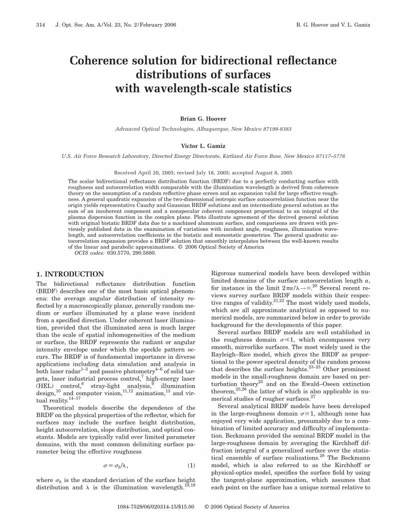
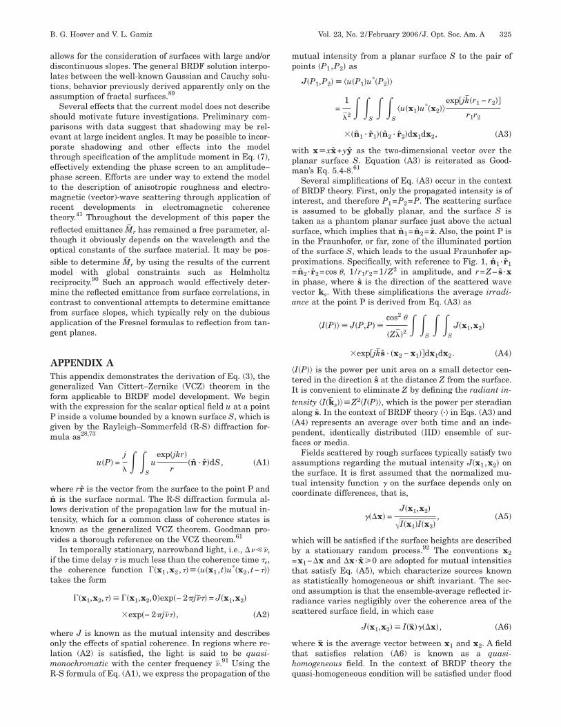
ig. 1. Geometry and notation relevant to derivation of theRDF at point P from the coherence between the surface points1 and x2. x=x1−x2.
f spatial inhomogeneities. As demonstrated in Appendix, the average scattered radiant intensity as a function ofave vector is then given by the generalized VCZ theorems
�I�ks�� =AMr cos2 �s
�2�� ��x�exp�− jks · x�dx,
�3�
here ks is the wave vector associated with scattereduasi-monochromatic light of center wavelength �, A ishe illuminated area, Mr is the average reflected emit-ance (also known as exitance) over the surface, and ��x�s the normalized mutual intensity on the surface as aunction of directed spatial separation.62 Dependence of¯
r and ��x� on the incident wave vector is implicit inq. (3). For application of Eq. (3) the average surface is
aken to be coincident with the xy plane, and the scat-ered wave vector is restricted to the xz plane. Equation3) provides the BRDF over the entire reflected hemi-phere by rotation of the surface and the vector argumentx= xx+ yy of the mutual intensity function about theaxis. The geometry of Eq. (3) is illustrated in Fig. 1.The derivation places several restrictions on the sur-
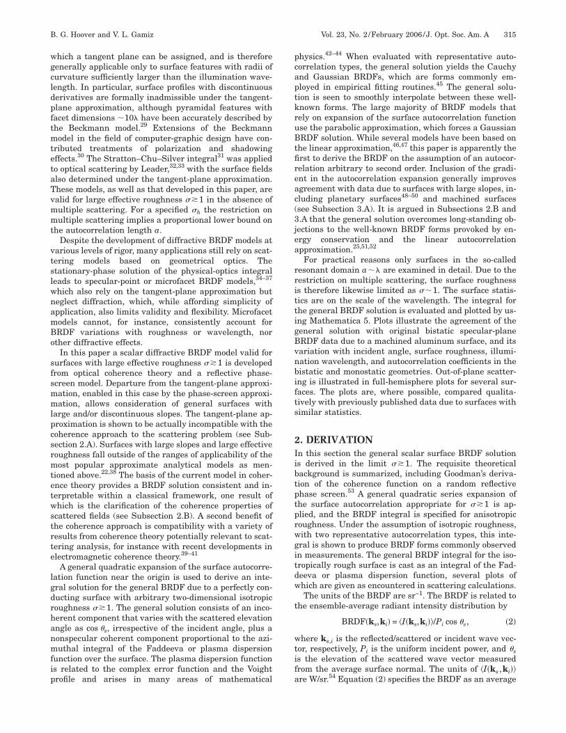
ace in addition to ��1, primarily that neither shadowingor multiple scattering can occur. Following Goodman,53
he field at the surface is expressed as a function of theurface height h�x� as
u�x� = a�x�exp�jki · x�exp�2�j
��1 + cos �i�h�x�
= a�x�exp�jki · x�expj�x��, �4�
here a�x� is the scattered amplitude and ki is the centerave vector incident at the elevation angle �i relative to
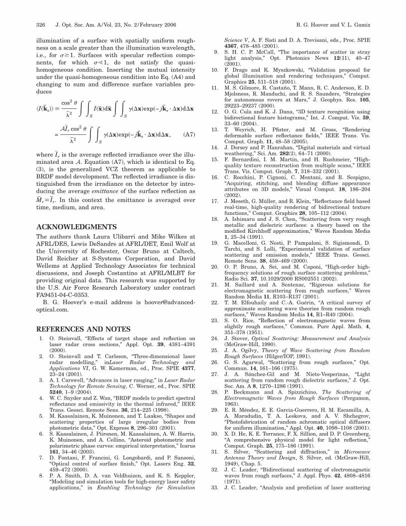
he average surface normal. Figure 2 illustrates the ge-metry of Eq. (4).
ig. 2. Illustration of the phase-screen approximation of thecattered field on the rough surface. The field is specified on theirtual surface Sps just above the actual surface, in contrast withhe tangent-plane approximation in which the field is specifiedn the surface facets Stp, where the radius of curvature is suffi-iently larger than the wavelength. The phase difference due to aateral separation of surface points is ki ·x, while the phase dif-erence due to the surface height h�x� is kh�x��1+cos �i�. Thengle �s is not relevant in the phase-screen approximation as it isn the tangent-plane approximation.
fi�mtsppttsmtcft
l
rtfm
wfipvir
BscspcTr
uG
wcV
WvIc
wot
wsw(s�tt
BSttrtm�nmis�eplstpnta
1Tt
B. G. Hoover and V. L. Gamiz Vol. 23, No. 2 /February 2006 /J. Opt. Soc. Am. A 317
As shown in Fig. 2, the surface on which the scatteredeld is specified under the phase-screen approximationSps� differs from that under the tangent-plane approxi-ation �Stp�. Both approximations are based on applica-
ion of the Helmholtz integral28 but differ in the boundaryurface on which the field is specified. Under the tangent-lane approximation the term 1+cos �i in Eq. (4) is re-laced by cos �s+cos �i, a distinction that affects not onlyhe model solution but also the fundamental interpreta-ion of the scattering process. Since it depends on bothurface position x and scattering direction �s, the secondoment of the field under the tangent-plane approxima-
ion is a radiance function and therefore inadmissible as aoherence function in Eq. (3).57 The implications of thisundamental incompatibility should be fully appreciatedhrough further investigations.
From Eq. (4) the phase variance and phase autocorre-ation of the scattered field are
�2 = 2���1 + cos �i��2, �5�
R�x� = �2�
��1 + cos �i�2
Rh�x�, �6�
espectively, where Rh�x� is the autocorrelation of thewo-dimensional random process that describes the sur-ace heights. In Eq. (4) the amplitude a�x� and the phase�x� are assumed to be uncorrelated, allowing the nor-alized mutual intensity to be expressed as
��x� ��u�x�u*�x − x��
��u2�x���u2�x − x��=
exp�jki · x�
�a2�x���a�x�a�x
− x���exp j�x� − �x − x����, �7�
here the quasi-homogeneous assumption allows simpli-cation of the denominator. Under the conventionalhase-screen approximation the scattered amplitude a�x�aries with x much more slowly than does the phase �x�,n which case the normalized mutual intensity on theough surface becomes
��x� = exp�jki · x��exp j�x� − �x − x����. �8�
ecause the conventional phase-screen approximation as-umes that every point on the surface responds identi-ally to the incident field, it should be more accurate inpecifying an electromagnetic scattered field componenterpendicular to the incident plane (s polarization) than aomponent parallel to the incident plane (p polarization).his is an important consideration in comparison of theesults of the scalar model with data.
The ensemble average in Eq. (8) can be evaluated bysing the second-order characteristic function with aaussian distribution of surface heights to yield
��x� = exp�jki · x�exp − �21 − �h�x���, �9�
here �h�x��Rh�x� /�h2 is the normalized surface auto-
orrelation function.53 Substitution of this result into theCZ theorem of Eq. (3) provides the BRDF as
�I�ks,ki�� =AMr cos2 �s
�2�� exp − �
21 − �h�x���
�expj�ki − ks� · x�dx. �10�
ith k� ki− ks, k ·x represents the scattered wave-ector distance from the direction of specular reflection.n circular polar coordinates the BRDF expression be-omes
�I�ks,ki�� =AMr cos2 �s
�2�
0
��0
2�
�exp − �21 − �h�x���
�expj�k · x��rd dr, �11�
ith the integration understood to cover the plane of co-rdinate differences on the surface. In the coordinate sys-em �r , � we have
k · x = − kr�A cos + B sin �, �12�
ith A�sin �s cos �s+sin �i cos �i and B�sin �i sin �i, theubscripts i and s referring to the incident and scatteredave vectors. The azimuth angle �i�s� of the incident
scattered) plane wave should be distinguished from theurface azimuth . The ranges of � and �i are 0,� /2� and−� ,��, respectively, and �s=0 or �, with ks confined tohe xz plane. These are standard notations in the descrip-ion of BRDF instrumentation.63
. Large-Roughness Approximationeries expansion of the surface autocorrelation �h�x� inhe limit of large effective roughness ��1 allows the in-egral of Eq. (11) to be developed for an arbitrary autocor-elation and evaluated for a general isotropic autocorrela-ion. With reference to Eq. (9), since for large �
2 theutual intensity falls off rapidly as �h�x� decreases from
h�0�=1, an approximation valid for large effective rough-ess is provided by expansion of �h�x� for small argu-ents. The dependence of the mutual intensity on �h�x�
s, however, generally not entirely evident in an expan-ion centered on the origin x=0, since by definitionh�x� is an even function with �h�0�=1, which for a gen-ral surface implies that the gradient ��h vanishes in aoint singularity at the origin. Due largely to this singu-arity, the autocorrelation expansion has been controver-ial among scattering theorists,64 which may explain whyhe general quadratic expansion has apparently not ap-eared earlier. Our position that the singularity can be ig-ored is based less on mathematical than on physical in-uition. To avoid the singularity, we expand theutocorrelation about the vector �x in the limit �→0.
. Anisotropic Roughnesshe normalized surface autocorrelation is expanded in
wo dimensions as65
Ao�
Tasviiltttctt
2Afasv
wdriB
w
i
l
a
zfrn
tat
wtruy
Tsm
ccawwass
o(ptccwteo
o
318 J. Opt. Soc. Am. A/Vol. 23, No. 2 /February 2006 B. G. Hoover and V. L. Gamiz
�h�x� � 1 + lim�→0
x · ��h��x + 12 �x · ���x · ��h���x� .
�13�
pplication of the gradient operator in circular polar co-rdinates and adoption of the shorthand notation �s�hlim�→0���h /�s��x�, where s=r or , leads to
�h�x� � 1 + r��r�h� +
r�� �h� +
r2
2��rr�h� +
2
2r2 �� �h�
+ ��r �h�. �14�
he derivatives �r�h ,� �h , . . . are functions of the azimuthngle in the case of general anisotropic roughness. Sub-titution from Eq. (12) and relation (14) into Eq. (11) pro-ides an integral expression for the BRDF of a general an-sotropically rough surface with ��1. Evaluation of thisntegral is generally difficult due to the mixed terms in re-ation (14) and the azimuthal dependence of the deriva-ives, although it might be simplified by approximation ofhe autocorrelation by planar wedges over azimuthal in-ervals. The prevalence of anisotropic roughness in pro-essed surfaces should motivate future investigation ofhe general theory; however, in this paper subsequent at-ention is limited to isotropic roughness.
. Isotropic Roughnesssurface with isotropic roughness is described by a sur-
ace autocorrelation with azimuthal symmetry, for whichll derivatives with respect to vanish. In this case sub-titution from Eq. (12) and relation (14) into Eq. (11) pro-ides the BRDF as
�I�ks,ki�� �AMr cos2 �s
�2�
0
��0
2�
�exp− jkr�A cos + B sin ��d
�exp��2��r�h�r +
�2
2��rr�h�r2rdr, �15�
ith A and B as defined following Eq. (12). Note that theerivatives �r�h and �rr�h are constants on an isotropicallyough surface. The integral over azimuth is evaluated byntroducing the variables � and � such that A=� cos � and=� sin �, which leads to66
�0
2�
exp− jk�r cos� − ���d = 2�J0�k�r�, �16�
here J0 is the zeroth-order Bessel function and
� = �sin2 �s + sin2 �i + 2 sin �i sin �s cos �i cos �s �17�
s the bidirectional independent variable of the BRDF.Substitution of the result of Eq. (16) into relation (15)
eaves the BRDF expression
�I�ks,ki�� �2�AMr cos2 �s
�2exp��v2��
0
�
rJ0�k�r�
�exp− ��r + v�2�dr �18�
fter completing the square in the exponent and setting
v � �r�h/�rr�h, �19�
� � �2��rr�h�/2. �20�
The integral in relation (18) is the Fourier–Bessel oreroth-order Hankel transform of a shifted Gaussianunction.67 The radial derivatives of the isotropicallyough surface are hereafter represented in the simplifiedotation �1��r�h and �2��rr�h.It is instructive to examine the representative forms of
he BRDF solution as the derivatives �1 and �2 individu-lly go to 0. With �1=0 the solution of relation (18) leadsransparently to the Gaussian BRDF68
�I�ks,ki�� ��AMr cos2 �s
�2�exp�−
�k��2
4� , �21�
hich is consistent with models that neglect the role ofhe gradient ��h by assuming a Gaussian surface autocor-elation function. With �2=0 the variable v cannot besed. Returning in this case to relation (15) and Eq. (16)ields the Cauchy BRDF69
�I�ks,ki�� �2�AMr cos2 �s
�2
�2��1�
�4�1
2 + �k��2�3/2. �22�
he Cauchy BRDF is commonly observed in data due tourfaces with large slopes48–50 and as a result is com-only employed in empirical fitting routines.45
The results of relations (21) and (22) suggest a usefullassification, according to the shape of the surface auto-orrelation, of isotropically rough surfaces that satisfy thessumptions of the model. Such surfaces with ��2�� ��1�ill be referred to as Gaussian-like surfaces, while thoseith ��1�� ��2� will be referred to as Cauchy-like surfaces,lthough the actual functional form of the general BRDFolution will generally differ significantly from the repre-entative forms of relations (21) and (22).
General BRDF solution for isotropic roughness in termsf the plasma dispersion function. The integral of relation18) can be recast as an integral of the Faddeeva orlasma dispersion function over a horizontal contour inhe complex plane. The resulting solution suggests a de-omposition of the BRDF into coherent and incoherentomponents as well as a mathematical analogy betweenave scattering from rough surfaces and wave propaga-
ion in hot, underdense plasmas.70 The integrals consid-red are also similar to those encountered in the analysisf generalized Bessel–Gauss beams.72
The Fourier–Bessel or zeroth-order Hankel transformf an arbitrary circularly symmetric function g�r� is67,73
EEt
wfsm
w
TtfiXt�
wsbf
wah
B
crapcprc(twlsrw(ftnefptctstisttds�
adfttIfiqpated(5�
ltrg
B. G. Hoover and V. L. Gamiz Vol. 23, No. 2 /February 2006 /J. Opt. Soc. Am. A 319
B g�r�� = G�R� =�0
�
rJ0�Rr�g�r�dr. �23�
xpressing the Bessel function in its integral form, as inq. (16), and changing the order of integrations in rela-
ion (18) gives
B exp− ��r + v�2�� = G�R�
=1
2��
0
2��0
�
r exp�− jRr cos �
�exp− ��r + v�2�drd
=1
2��
0
2�
G1�R cos �d , �24�
here the subscript 1 denotes the one-dimensional trans-orm and R= k� from relation (18). With the use of thehorthand notation X� k� cos , standard substitutionethods with t=���r+v+ jX /2�� lead to
G1�X� =1
�exp�− �v2 − �2���
−j�
�
t exp�− t2�dt + ��
��v +jX
2���
−j�
�
exp�− t2�dt , �25�
here
� � jv�� −X
2��. �26�
he contour of integration in Eq. (25) is a line parallel tohe real axis in the right half of the complex plane. Therst integral in Eq. (25) produces 1
2 exp��2�, the terms inof which cancel with the prefactor, while the second in-
egral is the complementary complex error function� erfc�−j�� /2.42 Slight rearrangement leads to
G1�X� =exp�− �v2�
2��1 − ����v +
jX
2��exp�− �2�erfc�− j��
=exp�− �v2�
2��1 − ����v +
jX
2��w��� , �27�
here w�z�=K�z�+ jL�z� is the Faddeeva or plasma disper-ion function.42–44,70,71 Inserting the expression for G1ack into Eq. (24), we express the Fourier–Bessel trans-orm as
G�R� =exp�− �v2�
2��1 −��
��
0
� �v +jk� cos
2��w���d
=exp�− �v2�
2��1 +
k�
2����
0
�
L����cos �d , �28�
here the final equality follows because w��� is analyticnd Hermitian along the horizontal contour in the upperalf of the complex plane.44,70
Inserting Eq. (28) into relation (18) gives the generalRDF solution for the isotropically rough surface as
�I�ks,ki�� ��AMr cos2 �s
�2��1 +
k�
2����
0
�
L����cos �d .
�29�
The solution of relation (29) is a sum of incoherent andoherent terms. The incoherent term produces an averageadiant intensity proportional to cos2 �s (not cos �s, as forLambertian source),74 which leaves the integral of the
lasma dispersion function to represent the BRDF due tooherence on the surface. Calculations of L�z� have beenlotted in several references.44,70 L�z� tends to 0 as theeal part of its argument goes to 0 in the upper half of theomplex plane Im�z��0�. With Re ��1/�h���2�, relation29) therefore implies that the derived BRDF converges tohe incoherent solution ��AMr cos2 �s� / �2� for surfacesith sufficiently narrow autocorrelation or sufficiently
arge roughness. Referring to Eq. (9), the mutual inten-ity associated with the incoherent solution is quite nar-ow as expected. Coherence theory reveals that associatedith a general coherence function are both propagating
low-frequency) and nonpropagating or evanescent (high-requency) components.74–76 It has been demonstratedhat the partition of energy between propagating and eva-escent components varies smoothly between the incoher-nt and coherent limits of a Gaussian coherenceunction.75 Since the BRDF solution accounts for theropagating component only, these results from coherenceheory imply that the BRDF should not be expected toonserve energy. The factor � in the denominator of rela-ion (29) ensures that the BRDF solution does not con-erve energy with variations in roughness or autocorrela-ion width. Relation (29) specifically predicts that thencoherent BRDF solution vanishes, i.e., that the fieldcattered from such a surface is purely evanescent, due tohe limit �→� as �h�x�→��x�.77 To reiterate, contraryo objections in the scattering literature,51,52 the BRDFoes not conserve energy in general, and the energy in theolution derived here varies smoothly with the parameter.Computer routines for the numerical calculation of L�z�
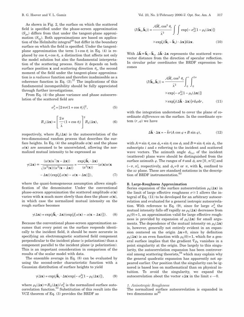
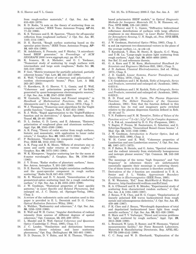
re readily available,44,78 although the variable depen-ences implied by Eq. (26) and relation (29) must be care-ully specified. The most suitable routine will depend onhe application, in particular on whether the solution ofhe forward or the inverse scattering problem is required.n the forward problem the BRDF is computed for speci-ed surface parameters, while the inverse problem re-uires a search algorithm to find surface parameters thatrovide the best fit to data. A comparison of algorithmsvailable for L��� is beyond the scope of this paper—herehe built-in complex error function routine in Math-matica 5 (Ref. 78) is utilized for calculation of the plasmaispersion function and the BRDF integral of relation29). Figures 3 and 4 illustrate results of the Mathematica
routine in contour plots of the integrand �L����cos � /�� of the coherent component of the general so-
ution [relation (29)] for two scattering geometries andwo sets of surface parameters. In these figures white cor-esponds to 0, black corresponds to the minimum inte-rand value, and contours are drawn at consistent inte-
gsss�
lesalircgrpw
3Tpteetw
tctiadwrwtctfriampr
Fnifalpl=(u
Fnispc�=
320 J. Opt. Soc. Am. A/Vol. 23, No. 2 /February 2006 B. G. Hoover and V. L. Gamiz
rand values across all of the plots. At a particularcattering angle �s the coherent component of the BRDFolution is proportional to the integral over the corre-ponding horizontal line. Note that �L����cos � /���0 forin the upper half of the complex plane.44,70
The characteristics of the general BRDF solution of re-ation (29) are illustrated in Section 3 through plots rel-vant to several applications of the forward and inversecattering problems. Applications to the inverse problemre representative of the derived solution and do not uti-ize a search/optimization algorithm. The general solutions examined with variations of incident angle, surfaceoughness, illumination wavelength, and autocorrelationoefficients in the specular-plane bistatic and monostaticeometries, and over the full scattered hemisphere. Plotselevant to the forward problem are, where possible, com-ared qualitatively with published data due to surfacesith similar statistics.
. RESULTShe general BRDF solution given by relation (29) is de-endent on eight parameters: the source (�i, �i, and �),he surface (�h, �1, and �2), and the observation param-ters (�s and �s). Practical considerations and the math-matical assumptions of the model place restrictions onhe surface parameters as follows: Referring to Eq. (9),ithout introducing higher derivatives of the surface au-
ig. 3. Contour plots of the integrand of the coherent compo-ent of the general BRDF solution, which is proportional to the
maginary part of the plasma dispersion function, for two sur-aces, for scattering in the specular plane at two incident angles,s functions of the scattering angle �s and the azimuthal corre-ation variable . The coherent component of the BRDF at �s isroportional to the integral over the corresponding horizontaline. Fixed parameters for these plots are �=1 �m, �1−0.005 �m−1, �2=−0.005 �m−2, and �=2 [(a), (b)] or �=3 [(c),
d)]. White represents 0, and dark shades represent negative val-es in gray-scale coding.
ocorrelation, the assumption of large effective roughnessan be approximately imposed as �h�� /4��0.08�. Forhe following (other than Figs. 7 and 10) the wavelengths fixed at �=1 �m. The second derivative of the surfaceutocorrelation is fixed at �2=−0.005 �m−2, and the firsterivative is limited to the range −0.05 �m−1��1�0,hich places a conservative lower bound on the autocor-
elation width of a�25 �m. Multiple scattering, forhich the model does not account, has been shown
hrough the appearance of coherent backscattering to oc-ur on surfaces for which the ratio �h /a�0.2.79 Imposinghe upper bound �h�5 �m should therefore avoid sur-aces with significant multiple scattering. The surface cor-esponding to the plots in Figs. 7 and 10 below is specifiedn the literature and has a larger autocorrelation widthnd larger roughness for which the assumptions of theodel still hold. Computations of the two-dimensional
lots of specular-plane bistatic scattering with � /100esolution take approximately 30 s in Mathematica 5 un-
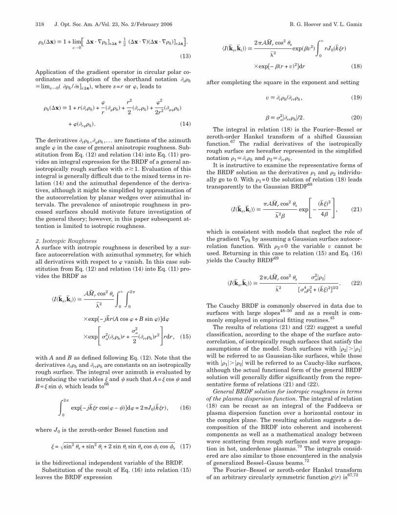
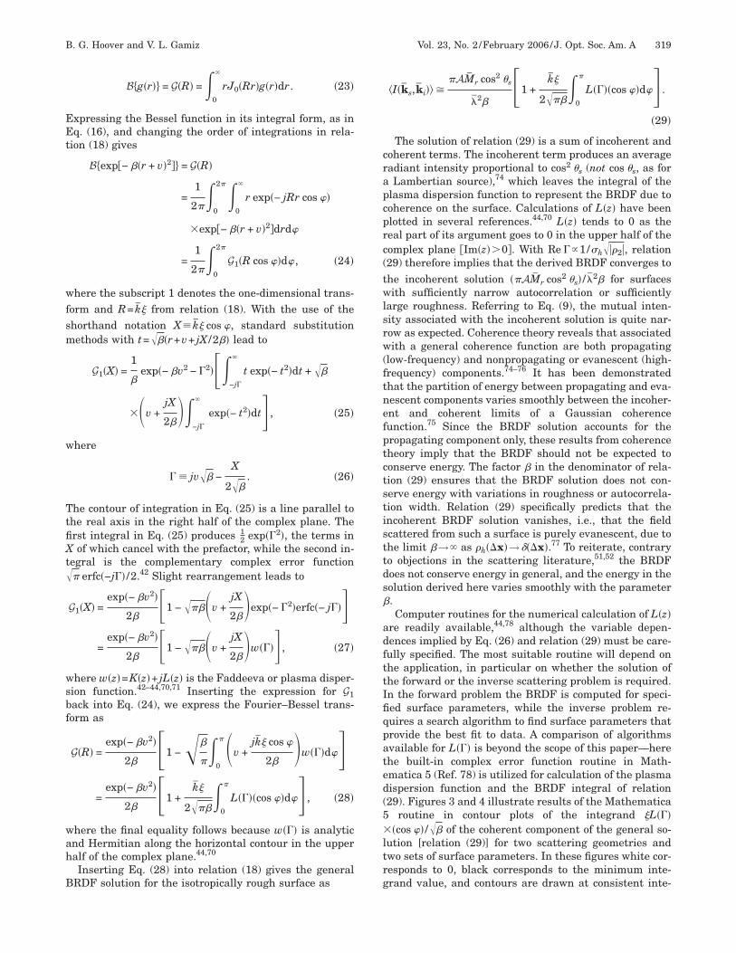
ig. 4. Contour plots of the integrand of the coherent compo-ent of the general BRDF solution, which is proportional to the
maginary part of the plasma dispersion function, for the twourfaces specified in Fig. 3, for scattering normal to the specularlane, as functions of the scattering angle �s and the azimuthalorrelation variable . Fixed parameters for these plots are (a)=1 �m, �1=−0.005 �m−1, �2=−0.005 �m−2, and �=2 or (b) �3.
d-
wtwpcriwcGoobsf5t0wbof
A
1TttissiMfois�cwtftctftdo
dtCaitrm
�ddbti
FfG=Tav
B. G. Hoover and V. L. Gamiz Vol. 23, No. 2 /February 2006 /J. Opt. Soc. Am. A 321
er the Microsoft Windows XP operating system on a 1.6GHz Intel Pentium 4 Mobile CPU with 512 Mbyte RAM.
The relatively little published data due to surfaces withavelength-scale statistics against which the results of
he model can be compared are summarized as follows,ith the illumination wavelength and reported surfacearameters given in the format �� ,�h ,a� �m. The much-ited paper of O’Donnell and Méndez provides plots of theadiant intensity measured in the specular plane due tollumination at several angles �i of a gold surface with theell-defined statistics (0.6328, 2.3, 21) (Ref. 79); the auto-
orrelation of this surface is, however, almost exactlyaussian, which relegates comparisons with the resultsf the current model to the pure Gaussian BRDF solutionf relation (21). Several authors have reported measuredackscattered or monostatic BRDFs due to surfaces withtatistics in the range of interest, specifically Renau et al.or two aluminum surfaces characterized by (0.6328, 7,0) and (0.6328, 1, 10) (Ref. 80) and Cheo and Renau forhe former surface at the illumination wavelengths.6328, 3.39, and 10.6 �m.81 Other data due to surfacesith wavelength-scale statistics are marginally relevantecause the surfaces are either one-dimensionally rough82
r nonconducting.19 Considerably more data due to sur-aces in this range are clearly needed.
. Variation with Incident Angle
. Specular-Plane Bistatiche specular-plane variation with the incident angle �i of
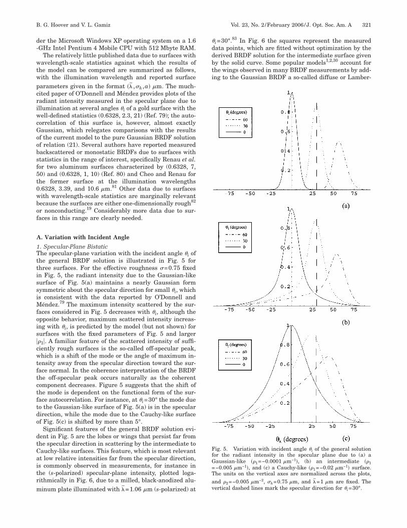
he general BRDF solution is illustrated in Fig. 5 forhree surfaces. For the effective roughness �=0.75 fixedn Fig. 5, the radiant intensity due to the Gaussian-likeurface of Fig. 5(a) maintains a nearly Gaussian formymmetric about the specular direction for small �i, whichs consistent with the data reported by O’Donnell and
éndez.79 The maximum intensity scattered by the sur-aces considered in Fig. 5 decreases with �i, although thepposite behavior, maximum scattered intensity increas-ng with �i, is predicted by the model (but not shown) forurfaces with the fixed parameters of Fig. 5 and larger�1�. A familiar feature of the scattered intensity of suffi-iently rough surfaces is the so-called off-specular peak,hich is a shift of the mode or the angle of maximum in-
ensity away from the specular direction toward the sur-ace normal. In the coherence interpretation of the BRDFhe off-specular peak occurs naturally as the coherentomponent decreases. Figure 5 suggests that the shift ofhe mode is dependent on the functional form of the sur-ace autocorrelation. For instance, at �i=30° the mode dueo the Gaussian-like surface of Fig. 5(a) is in the specularirection, while the mode due to the Cauchy-like surfacef Fig. 5(c) is shifted by more than 5°.
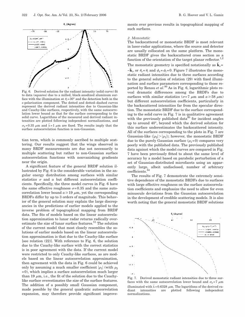
Significant features of the general BRDF solution evi-ent in Fig. 5 are the lobes or wings that persist far fromhe specular direction in scattering by the intermediate toauchy-like surfaces. This feature, which is most relevantt low relative intensities far from the specular direction,s commonly observed in measurements, for instance inhe (s-polarized) specular-plane intensity, plotted loga-ithmically in Fig. 6, due to a milled, black-anodized alu-inum plate illuminated with �=1.06 �m (s-polarized) at
i=30°.83 In Fig. 6 the squares represent the measuredata points, which are fitted without optimization by theerived BRDF solution for the intermediate surface giveny the solid curve. Some popular models1,2,30 account forhe wings observed in many BRDF measurements by add-ng to the Gaussian BRDF a so-called diffuse or Lamber-
ig. 5. Variation with incident angle �i of the general solutionor the radiant intensity in the specular plane due to (a) aaussian-like ��1=−0.0001 �m−1�, (b) an intermediate ��1−0.005 �m−1�, and (c) a Cauchy-like ��1=−0.02 �m−1� surface.he units on the vertical axes are normalized across the plots,nd �2=−0.005 �m−2, �h=0.75 �m, and �=1 �m are fixed. Theertical dashed lines mark the specular direction for �i=30°.
ttmman
lgsctcBiaidteolt[diweto=tlTme
ms
2TiasfT−stnpvsbttiwutAGdpd7asec
twtmiw
Ftfsralst�s
Ffidn
322 J. Opt. Soc. Am. A/Vol. 23, No. 2 /February 2006 B. G. Hoover and V. L. Gamiz
ian term, which is commonly ascribed to multiple scat-ering. Our results suggest that the wings observed inany BRDF measurements are due not necessarily toultiple scattering but rather to non-Gaussian surface
utocorrelation functions with nonvanishing gradientsear the origin.A significant feature of the general BRDF solution il-
ustrated by Fig. 6 is the considerable variation in the an-ular energy distribution among surfaces with similartatistics � and a but different autocorrelation coeffi-ients. Specifically, the three model curves in Fig. 6 havehe same effective roughness �=0.35 and the same auto-orrelation lower bound a�19 �m, yet the correspondingRDFs differ by up to 3 orders of magnitude. This behav-
or of the general solution may explain the large discrep-ncies in the predictions of earlier models applied to thenverse problem of topographical mapping from BRDFata. The fits of models based on the linear autocorrela-ion approximation to lunar radar returns radically over-stimate the size of lunar surface features.51 The solutionf the current model that most closely resembles the so-utions of earlier models based on the linear autocorrela-ion approximation is that due to the Cauchy-like surfacesee relation (22)]. With reference to Fig. 6, the solutionue to the Cauchy-like surface with the correct statisticss in poor agreement with the data. If the current modelere restricted to only Cauchy-like surfaces, as are mod-ls based on the linear autocorrelation approximation,hen agreement with the data in Fig. 6 could be achievednly by assuming a much smaller coefficient ��1� (with �20), which implies a surface autocorrelation much larger
han 19 �m, i.e., the fit of the solution due to the Cauchy-ike surface overestimates the size of the surface features.he addition of a possibly small Gaussian component,ade possible by the general quadratic autocorrelation
xpansion, may therefore provide significant improve-
ig. 6. Derived solution for the radiant intensity (solid curve) fito data (squares) due to a milled, black-anodized aluminum sur-ace with the illumination at �i=30° and the detection both in the-polarization component. The dotted and dotted–dashed curvesepresent the derived radiant intensities due to Gaussian-likend Cauchy-like surfaces, respectively, with the same autocorre-ation lower bound as that for the surface corresponding to theolid curve. Logarithms of the measured and derived radiant in-ensities are plotted following independent normalizations, and
h=0.35 �m and �=1 �m are fixed. The results imply that theurface autocorrelation function is non-Gaussian.
ents over previous results in topographical mapping ofuch surfaces.
. Monostatiche backscattered or monostatic BRDF is most relevant
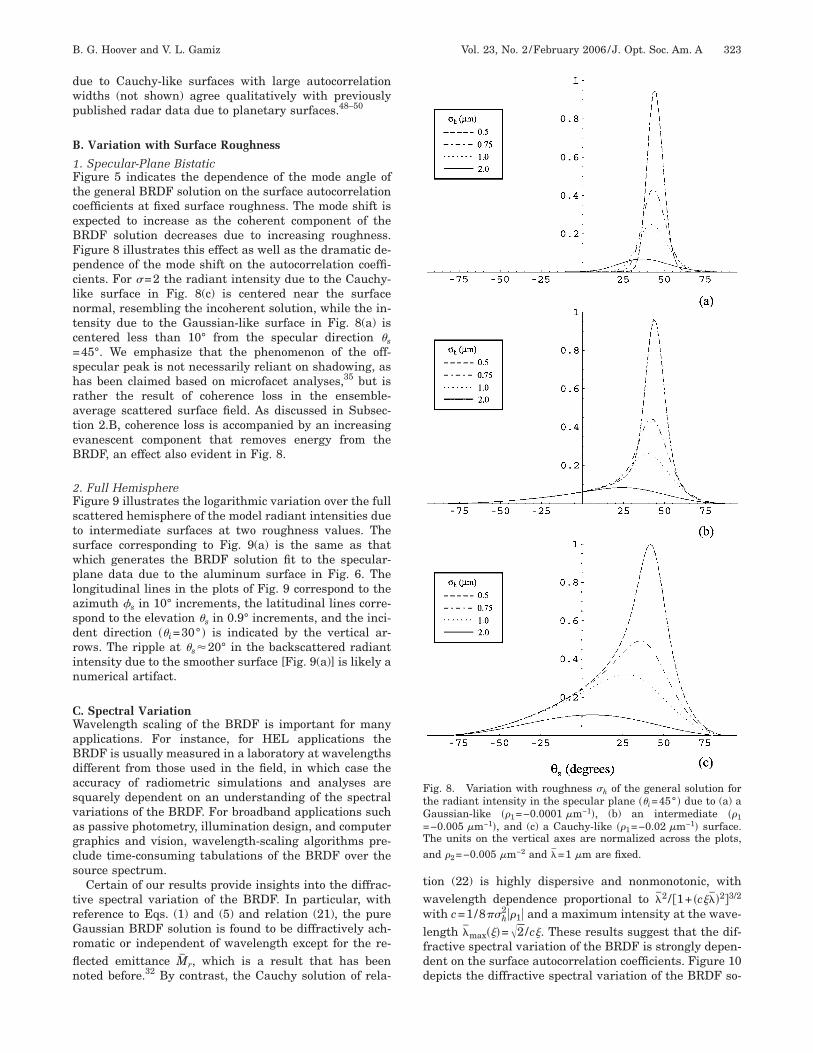
n laser-radar applications, where the source and detectorre usually collocated on the same platform. The mono-tatic BRDF gives the backscattered cross section as aunction of the orientation of the target planar reflector.1,2
he monostatic geometry is specified notationally as ks=ki, or �s=�i and �s=�i=0. Figure 7 illustrates the mono-tatic radiant intensities due to three surfaces accordingo the general solution of relation (29) with fixed illumi-ation and surface parameters corresponding to those re-orted by Renau et al.80 As in Fig. 6, logarithmic plots re-eal dramatic differences among the BRDFs due tourfaces with similar statistics (�=7 �m and a�58 �m)ut different autocorrelation coefficients, particularly inhe backscattered intensities far from the specular direc-ion. The monostatic BRDF due to the surface correspond-ng to the solid curve in Fig. 7 is in qualitative agreementith the previously published data80 for incident anglesp to around 40°, beyond which the derived solution forhis surface underestimates the backscattered intensity.ll of the surfaces corresponding to the plots in Fig. 7 areaussian-like ���2�� ��1��; however, the monostatic BRDFue to the purely Gaussian surface ��1=0� compares veryoorly with the published data. The previously publishedata against which the model curves are compared in Fig.have been previously fitted to about the same level of
ccuracy by a model based on parabolic perturbation of aet of Gaussian-distributed microfacets using an appar-ntly large, albeit undisclosed, number of arbitraryoefficients.84
The results of Fig. 7 demonstrate the extremely sensi-ive dependence of the monostatic BRDFs due to surfacesith large effective roughness on the surface autocorrela-
ion coefficients and emphasize the need to allow for eveninuscule deviations from the Gaussian autocorrelation
n the development of credible scattering models. It is alsoorth noting that the general monostatic BRDF solutions
ig. 7. Derived monostatic radiant intensities due to three sur-aces with the same autocorrelation lower bound and �h=7 �mlluminated with �=0.6328 �m. The logarithms of the derived ra-iant intensities are plotted following independentormalizations.
dwp
B
1FtceBFpclntc=shrateB
2Fstswplasdrin
CWaBdasvagcs
trGrfln
twwlfdd
FtG=Ta
B. G. Hoover and V. L. Gamiz Vol. 23, No. 2 /February 2006 /J. Opt. Soc. Am. A 323
ue to Cauchy-like surfaces with large autocorrelationidths (not shown) agree qualitatively with previouslyublished radar data due to planetary surfaces.48–50
. Variation with Surface Roughness
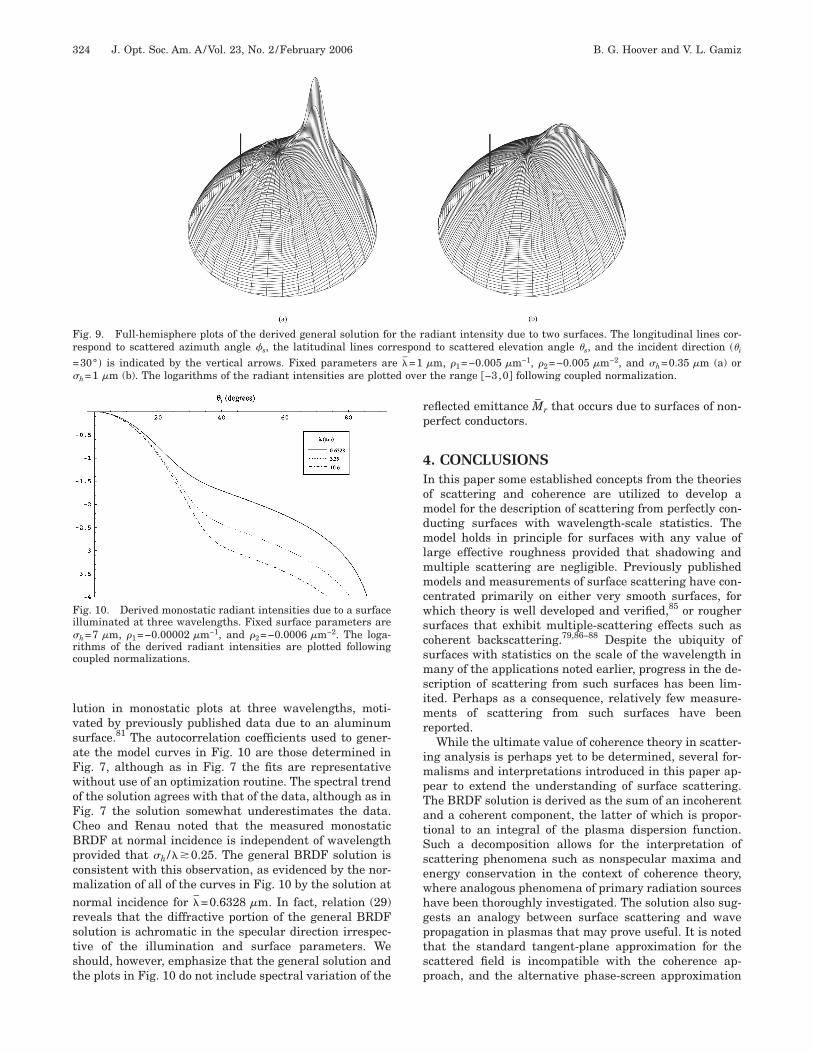
. Specular-Plane Bistaticigure 5 indicates the dependence of the mode angle ofhe general BRDF solution on the surface autocorrelationoefficients at fixed surface roughness. The mode shift isxpected to increase as the coherent component of theRDF solution decreases due to increasing roughness.igure 8 illustrates this effect as well as the dramatic de-endence of the mode shift on the autocorrelation coeffi-ients. For �=2 the radiant intensity due to the Cauchy-ike surface in Fig. 8(c) is centered near the surfaceormal, resembling the incoherent solution, while the in-ensity due to the Gaussian-like surface in Fig. 8(a) isentered less than 10° from the specular direction �s45°. We emphasize that the phenomenon of the off-pecular peak is not necessarily reliant on shadowing, asas been claimed based on microfacet analyses,35 but isather the result of coherence loss in the ensemble-verage scattered surface field. As discussed in Subsec-ion 2.B, coherence loss is accompanied by an increasingvanescent component that removes energy from theRDF, an effect also evident in Fig. 8.
. Full Hemisphereigure 9 illustrates the logarithmic variation over the fullcattered hemisphere of the model radiant intensities dueo intermediate surfaces at two roughness values. Theurface corresponding to Fig. 9(a) is the same as thathich generates the BRDF solution fit to the specular-lane data due to the aluminum surface in Fig. 6. Theongitudinal lines in the plots of Fig. 9 correspond to thezimuth �s in 10° increments, the latitudinal lines corre-pond to the elevation �s in 0.9° increments, and the inci-ent direction ��i=30° � is indicated by the vertical ar-ows. The ripple at �s�20° in the backscattered radiantntensity due to the smoother surface [Fig. 9(a)] is likely aumerical artifact.
. Spectral Variationavelength scaling of the BRDF is important for many
pplications. For instance, for HEL applications theRDF is usually measured in a laboratory at wavelengthsifferent from those used in the field, in which case theccuracy of radiometric simulations and analyses arequarely dependent on an understanding of the spectralariations of the BRDF. For broadband applications suchs passive photometry, illumination design, and computerraphics and vision, wavelength-scaling algorithms pre-lude time-consuming tabulations of the BRDF over theource spectrum.
Certain of our results provide insights into the diffrac-ive spectral variation of the BRDF. In particular, witheference to Eqs. (1) and (5) and relation (21), the pureaussian BRDF solution is found to be diffractively ach-
omatic or independent of wavelength except for the re-ected emittance Mr, which is a result that has beenoted before.32 By contrast, the Cauchy solution of rela-
ion (22) is highly dispersive and nonmonotonic, withavelength dependence proportional to �2 / 1+ �c���2�3/2
ith c=1/8��h2��1� and a maximum intensity at the wave-
ength �max���=�2/c�. These results suggest that the dif-ractive spectral variation of the BRDF is strongly depen-ent on the surface autocorrelation coefficients. Figure 10epicts the diffractive spectral variation of the BRDF so-
ig. 8. Variation with roughness �h of the general solution forhe radiant intensity in the specular plane ��i=45° � due to (a) aaussian-like ��1=−0.0001 �m−1�, (b) an intermediate ��1−0.005 �m−1�, and (c) a Cauchy-like ��1=−0.02 �m−1� surface.he units on the vertical axes are normalized across the plots,nd �2=−0.005 �m−2 and �=1 �m are fixed.
lvsaFwoFCBpcmnrstst
rp
4Iomdmlmmcwscsmsimr
impTatSsewhgptsp
Fi�rc
Fr=� d over
324 J. Opt. Soc. Am. A/Vol. 23, No. 2 /February 2006 B. G. Hoover and V. L. Gamiz
ution in monostatic plots at three wavelengths, moti-ated by previously published data due to an aluminumurface.81 The autocorrelation coefficients used to gener-te the model curves in Fig. 10 are those determined inig. 7, although as in Fig. 7 the fits are representativeithout use of an optimization routine. The spectral trendf the solution agrees with that of the data, although as inig. 7 the solution somewhat underestimates the data.heo and Renau noted that the measured monostaticRDF at normal incidence is independent of wavelengthrovided that �h /��0.25. The general BRDF solution isonsistent with this observation, as evidenced by the nor-alization of all of the curves in Fig. 10 by the solution at
ormal incidence for �=0.6328 �m. In fact, relation (29)eveals that the diffractive portion of the general BRDFolution is achromatic in the specular direction irrespec-ive of the illumination and surface parameters. Wehould, however, emphasize that the general solution andhe plots in Fig. 10 do not include spectral variation of the
ig. 10. Derived monostatic radiant intensities due to a surfacelluminated at three wavelengths. Fixed surface parameters areh=7 �m, �1=−0.00002 �m−1, and �2=−0.0006 �m−2. The loga-ithms of the derived radiant intensities are plotted followingoupled normalizations.
ig. 9. Full-hemisphere plots of the derived general solution foespond to scattered azimuth angle �s, the latitudinal lines cor30° � is indicated by the vertical arrows. Fixed parameters arh=1 �m (b). The logarithms of the radiant intensities are plotte
eflected emittance Mr that occurs due to surfaces of non-erfect conductors.
. CONCLUSIONSn this paper some established concepts from the theoriesf scattering and coherence are utilized to develop aodel for the description of scattering from perfectly con-
ucting surfaces with wavelength-scale statistics. Theodel holds in principle for surfaces with any value of
arge effective roughness provided that shadowing andultiple scattering are negligible. Previously publishedodels and measurements of surface scattering have con-
entrated primarily on either very smooth surfaces, forhich theory is well developed and verified,85 or rougher
urfaces that exhibit multiple-scattering effects such asoherent backscattering.79,86–88 Despite the ubiquity ofurfaces with statistics on the scale of the wavelength inany of the applications noted earlier, progress in the de-
cription of scattering from such surfaces has been lim-ted. Perhaps as a consequence, relatively few measure-
ents of scattering from such surfaces have beeneported.
While the ultimate value of coherence theory in scatter-ng analysis is perhaps yet to be determined, several for-
alisms and interpretations introduced in this paper ap-ear to extend the understanding of surface scattering.he BRDF solution is derived as the sum of an incoherentnd a coherent component, the latter of which is propor-ional to an integral of the plasma dispersion function.uch a decomposition allows for the interpretation ofcattering phenomena such as nonspecular maxima andnergy conservation in the context of coherence theory,here analogous phenomena of primary radiation sourcesave been thoroughly investigated. The solution also sug-ests an analogy between surface scattering and waveropagation in plasmas that may prove useful. It is notedhat the standard tangent-plane approximation for thecattered field is incompatible with the coherence ap-roach, and the alternative phase-screen approximation
adiant intensity due to two surfaces. The longitudinal lines cor-d to scattered elevation angle �s, and the incident direction ��i
�m, �1=−0.005 �m−1, �2=−0.005 �m−2, and �h=0.35 �m (a) orthe range −3,0� following coupled normalization.
r the rrespone �=1
adlta
spepteptmrtrtosmrmcfag
ATgfwPgm
wnltkv
itt
wolmR
mp
wpm
oiitsiop=iva
�tIta(pf
attc
wb=taors
wthq
B. G. Hoover and V. L. Gamiz Vol. 23, No. 2 /February 2006 /J. Opt. Soc. Am. A 325
llows for the consideration of surfaces with large and/oriscontinuous slopes. The general BRDF solution interpo-ates between the well-known Gaussian and Cauchy solu-ions, behavior previously derived apparently only on thessumption of fractal surfaces.89
Several effects that the current model does not describehould motivate future investigations. Preliminary com-arisons with data suggest that shadowing may be rel-vant at large incident angles. It may be possible to incor-orate shadowing and other effects into the modelhrough specification of the amplitude moment in Eq. (7),ffectively extending the phase screen to an amplitude–hase screen. Efforts are under way to extend the modelo the description of anisotropic roughness and electro-agnetic (vector)-wave scattering through application of
ecent developments in electromagnetic coherenceheory.41 Throughout the development of this paper theeflected emittance Mr has remained a free parameter, al-hough it obviously depends on the wavelength and theptical constants of the surface material. It may be pos-ible to determine Mr by using the results of the currentodel with global constraints such as Helmholtz
eciprocity.90 Such an approach would effectively deter-ine the reflected emittance from surface correlations, in
ontrast to conventional attempts to determine emittancerom surface slopes, which typically rely on the dubiouspplication of the Fresnel formulas to reflection from tan-ent planes.
PPENDIX Ahis appendix demonstrates the derivation of Eq. (3), theeneralized Van Cittert–Zernike (VCZ) theorem in theorm applicable to BRDF model development. We beginith the expression for the scalar optical field u at a pointinside a volume bounded by a known surface S, which is
iven by the Rayleigh–Sommerfeld (R-S) diffraction for-ula as28,73
u�P� =j
�� �
S
uexp�jkr�
r�n · r�dS, �A1�
here rr is the vector from the surface to the point P andˆ is the surface normal. The R-S diffraction formula al-ows derivation of the propagation law for the mutual in-ensity, which for a common class of coherence states isnown as the generalized VCZ theorem. Goodman pro-ides a thorough reference on the VCZ theorem.61
In temporally stationary, narrowband light, i.e., ���,f the time delay � is much less than the coherence time �c,he coherence function ��x1 ,x2 ,����u�x1 , t�u*�x2 , t−���akes the form
��x1,x2,�� � ��x1,x2,0�exp�− 2�j��� = J�x1,x2�
�exp�− 2�j���, �A2�
here J is known as the mutual intensity and describesnly the effects of spatial coherence. In regions where re-ation (A2) is satisfied, the light is said to be quasi-
onochromatic with the center frequency �.91 Using the-S formula of Eq. (A1), we express the propagation of the
utual intensity from a planar surface S to the pair ofoints �P1 ,P2� as
J�P1,P2� � �u�P1�u*�P2��
=1
�2� �
S� �
S
�u�x1�u*�x2��expjk�r1 − r2��
r1r2
��n1 · r1��n2 · r2�dx1dx2, �A3�
ith x�xx+yy as the two-dimensional vector over thelanar surface S. Equation (A3) is reiterated as Good-an’s Eq. 5.4-8.61
Several simplifications of Eq. (A3) occur in the contextf BRDF theory. First, only the propagated intensity is ofnterest, and therefore P1=P2=P. The scattering surfaces assumed to be globally planar, and the surface S isaken as a phantom planar surface just above the actualurface, which implies that n1= n2= z. Also, the point P isn the Fraunhofer, or far, zone of the illuminated portionf the surface S, which leads to the usual Fraunhofer ap-roximations. Specifically, with reference to Fig. 1, n1 · r1n2 · r2=cos �, 1 /r1r2=1/Z2 in amplitude, and r=Z− s ·x
n phase, where s is the direction of the scattered waveector ks. With these simplifications the average irradi-nce at the point P is derived from Eq. (A3) as
�I�P�� � J�P,P� �cos2 �
�Z��2� �
S� �
S
J�x1,x2�
�expjks · �x2 − x1��dx1dx2. �A4�
I�P�� is the power per unit area on a small detector cen-ered in the direction s at the distance Z from the surface.t is convenient to eliminate Z by defining the radiant in-ensity �I�ks���Z2�I�P��, which is the power per steradianlong s. In the context of BRDF theory �·� in Eqs. (A3) andA4) represents an average over both time and an inde-endent, identically distributed (IID) ensemble of sur-aces or media.
Fields scattered by rough surfaces typically satisfy twossumptions regarding the mutual intensity J�x1 ,x2� onhe surface. It is first assumed that the normalized mu-ual intensity function � on the surface depends only onoordinate differences, that is,
��x� =J�x1,x2�
�I�x1�I�x2�, �A5�
hich will be satisfied if the surface heights are describedy a stationary random process.92 The conventions x2x1−x and x · x�0 are adopted for mutual intensities
hat satisfy Eq. (A5), which characterize sources knowns statistically homogeneous or shift invariant. The sec-nd assumption is that the ensemble-average reflected ir-adiance varies negligibly over the coherence area of thecattered surface field, in which case
J�x1,x2� � I�x���x�, �A6�
here x is the average vector between x1 and x2. A fieldhat satisfies relation (A6) is known as a quasi-omogeneous field. In the context of BRDF theory theuasi-homogeneous condition will be satisfied under flood
ininhucd
�
wm(BtdMt
ATAtDWdptF
o
R
1
1
1
1
1
1
1
1
1
1
2
2
2
2
2
2
2
2
2
2
3
3
3
3
326 J. Opt. Soc. Am. A/Vol. 23, No. 2 /February 2006 B. G. Hoover and V. L. Gamiz
llumination of a surface with spatially uniform rough-ess on a scale greater than the illumination wavelength,
.e., for ��1. Surfaces with specular reflection compo-ents, for which ��1, do not satisfy the quasi-omogeneous condition. Inserting the mutual intensitynder the quasi-homogeneous condition into Eq. (A4) andhanging to sum and difference surface variables pro-uces
I�ks�� �cos2 �
�2� �
S
I�x�dx� �S
��x�exp�− jks · x�dx
=AIr cos2 �
�2� �
S
��x�exp�− jks · x�dx, �A7�
here Ir is the average reflected irradiance over the illu-inated area A. Equation (A7), which is identical to Eq.
3), is the generalized VCZ theorem as applicable toRDF model development. The reflected irradiance is dis-
inguished from the irradiance on the detector by intro-ucing the average emittance of the surface reflection as¯
r� Ir. In this context the emittance is averaged overime, medium, and area.
CKNOWLEDGMENTShe authors thank Laura Ulibarri and Mike Wilkes atFRL/DES, Lewis DeSandre at AFRL/DET, Emil Wolf at
he University of Rochester, Oscar Bruno at Caltech,avid Reicher at S-Systems Corporation, and Davidellems at Applied Technology Associates for technical
iscussions, and Joseph Costantino at AFRL/MLBT forroviding original data. This research was supported byhe U.S. Air Force Research Laboratory under contractA9451-04-C-0353.B. G. Hoover’s e-mail address is hoover@advanced-
ptical.com.
EFERENCES AND NOTES1. O. Steinvall, “Effects of target shape and reflection on
laser radar cross sections,” Appl. Opt. 39, 4381–4391(2000).
2. O. Steinvall and T. Carlsson, “Three-dimensional laserradar modelling,” inLaser Radar Technology andApplications VI, G. W. Kamerman, ed., Proc. SPIE 4377,23–24 (2001).
3. A. I. Carswell, “Advances in laser ranging,” in Laser RadarTechnology for Remote Sensing, C. Werner, ed., Proc. SPIE5240, 1–9 (2004).
4. W. C. Snyder and Z. Wan, “BRDF models to predict spectralreflectance and emissivity in the thermal infrared,” IEEETrans. Geosci. Remote Sens. 36, 214–225 (1998).
5. M. Kaasalainen, K. Muinonen, and T. Laakso, “Shapes andscattering properties of large irregular bodies fromphotometric data,” Opt. Express 8, 296–301 (2001).
6. S. Kaasalainen, J. Piironen, M. Kaasalainen, A. W. Harris,K. Muinonen, and A. Cellino, “Asteroid photometric andpolarimetric phase curves: empirical interpretation,” Icarus161, 34–46 (2003).
7. D. Fontani, F. Francini, G. Longobardi, and P. Sansoni,“Optical control of surface finish,” Opt. Lasers Eng. 32,459–472 (2000).
8. P. A. Smith, D. A. van Veldhuizen, and K. S. Keppler,“Modeling and simulation tools for high-energy laser safetyapplications,” in Enabling Technology for Simulation
Science V, A. F. Sisti and D. A. Trevisani, eds., Proc. SPIE4367, 478–485 (2001).
9. S. H. C. P. McCall, “The importance of scatter in straylight analysis,” Opt. Photonics News 12(11), 40–47(2001).
0. F. Drago and K. Myszkowski, “Validation proposal forglobal illumination and rendering techniques,” Comput.Graphics 25, 511–518 (2001).
1. M. S. Gilmore, R. Castaño, T. Mann, R. C. Anderson, E. D.Mjolsness, R. Manduchi, and R. S. Saunders, “Strategiesfor autonomous rovers at Mars,” J. Geophys. Res. 105,29223–29237 (2000).
2. O. G. Cula and K. J. Dana, “3D texture recognition usingbidirectional feature histograms,” Int. J. Comput. Vis. 59,33–60 (2004).
3. T. Weyrich, H. Pfister, and M. Gross, “Renderingdeformable surface reflectance fields,” IEEE Trans. Vis.Comput. Graph. 11, 48–58 (2005).
4. J. Dorsey and P. Hanrahan, “Digital materials and virtualweathering,” Sci. Am. 282(2), 64–71 (2000).
5. F. Bernardini, I. M. Martin, and H. Rushmeier, “High-quality texture reconstruction from multiple scans,” IEEETrans. Vis. Comput. Graph. 7, 318–332 (2001).
6. C. Rocchini, P. Cignoni, C. Montani, and R. Scopigno,“Acquiring, stitching, and blending diffuse appearanceattributes on 3D models,” Visual Comput. 18, 186–204(2002).
7. J. Meseth, G. Müller, and R. Klein, “Reflectance field basedreal-time, high-quality rendering of bidirectional texturefunctions,” Comput. Graphics 28, 105–112 (2004).
8. A. Ishimaru and J. S. Chen, “Scattering from very roughmetallic and dielectric surfaces: a theory based on themodified Kirchhoff approximation,” Waves Random Media1, 25–34 (1991).
9. G. Macelloni, G. Nesti, P. Pampaloni, S. Sigismondi, D.Tarchi, and S. Lolli, “Experimental validation of surfacescattering and emission models,” IEEE Trans. Geosci.Remote Sens. 38, 459–469 (2000).
0. O. P. Bruno, A. Sei, and M. Caponi, “High-order high-frequency solutions of rough surface scattering problems,”Radio Sci. 37, 10.1029/2000 RS002551 (2002).
1. M. Saillard and A. Sentenac, “Rigorous solutions forelectromagnetic scattering from rough surfaces,” WavesRandom Media 11, R103–R137 (2001).
2. T. M. Elfouhaily and C.-A. Guérin, “A critical survey ofapproximate scattering wave theories from random roughsurfaces,” Waves Random Media 14, R1–R40 (2004).
3. S. O. Rice, “Reflection of electromagnetic waves fromslightly rough surfaces,” Commun. Pure Appl. Math. 4,351–378 (1951).
4. J. Stover, Optical Scattering: Measurement and Analysis(McGraw-Hill, 1990).
5. J. A. Ogilvy, Theory of Wave Scattering from RandomRough Surfaces (Hilger/IOP, 1991).
6. G. S. Agarwal, “Scattering from rough surfaces,” Opt.Commun. 14, 161–166 (1975).
7. J. A. Sánchez-Gil and M. Nieto-Vesperinas, “Lightscattering from random rough dielectric surfaces,” J. Opt.Soc. Am. A 8, 1270–1286 (1991).
8. P. Beckmann and A. Spizzichino, The Scattering ofElectromagnetic Waves from Rough Surfaces (Pergamon,1963).
9. E. R. Méndez, E. E. Garcia-Guerrero, H. M. Escamilla, A.A. Maradudin, T. A. Leskova, and A. V. Shchegrov,“Photofabrication of random achromatic optical diffusersfor uniform illumination,” Appl. Opt. 40, 1098–1108 (2001).
0. X. D. He, K. E. Torrance, F. X. Sillion, and D. P. Greenberg,“A comprehensive physical model for light reflection,”Comput. Graph. 25, 175–186 (1991).
1. S. Silver, “Scattering and diffraction,” in MicrowaveAntenna Theory and Design, S. Silver, ed. (McGraw-Hill,1949), Chap. 5.
2. J. C. Leader, “Bidirectional scattering of electromagneticwaves from rough surfaces,” J. Appl. Phys. 42, 4808–4816(1971).
3. J. C. Leader, “Analysis and prediction of laser scattering
3
3
3
3
3
3
4
4
4
4
4
4
4
4
4
4
5
5
5
5
5
5
5
5
5
5
6
66
6
66
6
6
6
6
7
7
7
7
7
7
7
7
7
7
8
8
8
8
8
B. G. Hoover and V. L. Gamiz Vol. 23, No. 2 /February 2006 /J. Opt. Soc. Am. A 327
from rough-surface materials,” J. Opt. Soc. Am. 69,610–628 (1979).
4. R. D. Kodis, “A note on the theory of scattering from anirregular surface,” IEEE Trans. Antennas Propag. AP-14,77–82 (1966).
5. K. E. Torrance and E. M. Sparrow, “Theory for off-specularreflection from roughened surfaces,” J. Opt. Soc. Am. 57,1105–1114 (1967).
6. D. E. Barrick, “Rough surface scattering based on thespecular point theory,” IEEE Trans. Antennas Propag. AP-16, 449–454 (1968).
7. M. Ashikhmin, S. Premože, and P. Shirley, “A microfacet-based BRDF generator,” in Proceedings of ACMSIGGRAPH 2000 (www.siggraph.org), pp. 65–74.
8. K. Ivanova, M. A. Michalev, and O. I. Yordanov,“Numerical study of scattering by rough surfaces withintermediate and large scale roughness,” Radio Sci. 26,505–510 (1991).
9. F. Gori, “Matrix treatment for partially polarized, partiallycoherent beams,” Opt. Lett. 23, 241–243 (1998).
0. E. Wolf, “Unified theory of coherence and polarization ofrandom electromagnetic beams,” Phys. Lett. A 312,263–267 (2003).
1. O. Korotkova, B. G. Hoover, V. L. Gamiz, and E. Wolf,“Coherence and polarization properties of far-fieldsgenerated by quasi-homogeneous electromagnetic sources,”J. Opt. Soc. Am. A 22, 2547–2556 (2005).
2. W. Gautschi, “Error function and Fresnel integrals,” inHandbook of Mathematical Functions, 9th ed., M.Abramowitz and I. A. Stegun, eds. (Dover, 1972), Chap. 7.
3. W. J. Thompson, “Numerous neat algorithms for the Voightprofile function,” Comput. Phys. 7, 627–631 (1993).
4. R. J. Wells, “Rapid approximation to the Voight/Faddeevafunction and its derivatives,” J. Quant. Spectrosc. Radiat.Transf. 62, 29–48 (1999).
5. D. L. Jordan, G. D. Lewis, and E. Jakeman, “Emissionpolarization of roughened glass and aluminum surfaces,”Appl. Opt. 35, 3583–3590 (1996).
6. A. K. Fung, “Theory of radar scatter from rough surfaces,bistatic and monostatic, with application to lunar radarreturn,” J. Geophys. Res. 69, 1063–1073 (1964).
7. P. Beckmann, “Scattering by composite rough surfaces,”Proc. IEEE 53, 1012–1015 (1965).
8. A. K. Fung and R. K. Moore, “Effects of structure size onmoon and earth radar returns at various angles,” J.Geophys. Res. 69, 1075–1081 (1964).
9. W. K. Klemperer, “Angular scattering law for the moon at6-meter wavelength,” J. Geophys. Res. 70, 3798–3800(1965).
0. J. V. Evans, “Radar studies of planetary surfaces,” Annu.Rev. Astron. Astrophys. 7, 201–248 (1969).
1. D. E. Barrick, “Unacceptable height correlation coefficientsand the quasi-specular component in rough surfacescattering,” Radio Sci.5, 647–654 (1970).
2. K. E. Warnick and D. V. Arnold, “Generalization of thegeometrical-optics scattering limit for a rough conductingsurface,” J. Opt. Soc. Am. A 15, 2355–2361 (1998).
3. J. W. Goodman, “Statistical properties of laser specklepatterns,” in Laser Speckle and Related Phenomena, 2ndenlarged ed., J. C. Dainty, ed. (Springer-Verlag, 1984),Chap. 2.
4. A review of the radiometric units and notation used in thispaper is provided in E. L. Dereniak and D. G. Crowe,Optical Radiation Detectors (Wiley, 1984).
5. A. Walther, “Radiometry and coherence,” J. Opt. Soc. Am.58, 1256–1259 (1968).
6. E. Wolf and W. H. Carter, “Angular distribution of radiantintensity from sources of different degrees of spatialcoherence,” Opt. Commun. 13, 205–209 (1975).
7. L. Mandel and E. Wolf, Optical Coherence and QuantumOptics (Cambridge U. Press, 1995), Chap. 5.7.
8. J. C. Leader, “Similarities and distinctions betweencoherence theory relations and laser scatteringphenomena,” Opt. Eng. (Bellingham) 19, 593–601 (1980).
9. D. D. Duncan, D. V. Hahn, and M. E. Thomas, “Physics-
based polarimetric BRDF models,” in Optical DiagnosticMethods for Inorganic Materials III, L. M. Hanssen, ed.,Proc. SPIE 5192, 129–140 (2003).
0. B. G. Hoover and V. L. Gamiz, “Diffractive bidirectionalreflectance distributions of surfaces with large effectiveroughness in one dimension,” in Laser Radar Techniquesfor Atmospheric Sensing, U. N. Singh, ed., Proc. SPIE 5575,137–142 (2004).
1. J. W. Goodman, Statistical Optics (Wiley, 1985), Chap. 5.2. x and x represent two-dimensional vectors in the plane of
the average surface, i.e., x=xx+yy.3. T. Karabacak, Y. Zhao, M. Stowe, B. Quayle, G.-C. Wang,
and T.-M. Lu, “Large-angle in-plane light scattering fromrough surfaces,” Appl. Opt. 39, 4658–4668 (2000).
4. See Ref. 51 and references therein.5. G. A. Korn and T. M. Korn, Mathematical Handbook for
Scientists and Engineers (McGraw-Hill, 1961), Chap. 5.6. J. D. Jackson, Classical Electrodynamics, 2nd ed. (Wiley,
1975), Chap. 9.7. J. D. Gaskill, Linear Systems, Fourier Transforms, and
Optics (Wiley, 1978), Chap. 9.8. I. S. Gradshteyn and I. M. Ryzhik, Table of Integrals, Series
and Products, corrected and enlarged ed. (Academic, 1980),6.631(4).
9. I. S. Gradshteyn and I. M. Ryzhik, Table of Integrals, Seriesand Products, corrected and enlarged ed. (Academic, 1980),6.623(2).
0. B. D. Fried and S. D. Conte, The Plasma DispersionFunction: The Hilbert Transform of the Gaussian(Academic, 1961). Note that the function defined in thisreference has its real and imaginary parts switchedrelative to the plasma dispersion function defined in Refs.42–44 and 71.
1. V. N. Faddeeva and N. M. Terent’ev, Tables of Values of theFunction w�z�=e−z2
�1+2i /���0zet2dt� for Complex Argument,
V. A. Fok ed., translated by D. G. Fry (Pergamon, 1961).2. V. Bagini, F. Frezza, M. Santarsiero, G. Schettini, and G.
Schirripa-Spagnolo, “Generalized Bessel–Gauss beams,” J.Mod. Opt. 43, 1155–1166 (1996).
3. J. W. Goodman, Introduction to Fourier Optics, 2nd ed.(McGraw-Hill, 1996), Chap. 2.
4. W. H. Carter and E. Wolf, “Coherence properties ofLambertian and non-Lambertian sources,” J. Opt. Soc. Am.65, 1067–1071 (1975).
5. H. P. Baltes, B. Steinle, and G. Antes, “Spectral coherenceand the radiant intensity from statistically homogeneousand isotropic planar sources,” Opt. Commun. 18, 242–246(1976).
6. The meanings of the terms “high frequency” and “lowfrequency” in coherence theory are unfortunatelyessentially opposite their meanings in scattering theory.Use of these terms in this context is therefore avoided.
7. Derivatives of the � function are considered in T. B. A.Senior and J. L. Volakis, Approximate BoundaryConditions in Electromagnetics (IEEE Press, 1995).
8. E. W. Weisstein, “Erf,” from MathWorld–A Wolfram WebResource, http://mathworld.wolfram.com/Erf.html.
9. K. A. O’Donnell and E. R. Méndez, “Experimental study ofscattering from characterized random surfaces,” J. Opt.Soc. Am. A 4, 1194–1205 (1987).
0. J. Renau, P. K. Cheo, and H. G. Cooper, “Depolarization oflinearly polarized EM waves backscattered from roughmetals and inhomogeneous dielectrics,” J. Opt. Soc. Am. 57,459–466 (1967).
1. P. K. Cheo and J. Renau, “Wavelength dependence of totaland depolarized backscattered laser light from roughmetallic surfaces,” J. Opt. Soc. Am. 59, 821–826 (1969).
2. E. Marx and T. V. Vorburger, “Direct and inverse problemsfor light scattered by rough surfaces,” Appl. Opt. 29,3613–3626 (1990).
3. L. Brainard, W. Lynn, D. Ramer, and W. Shemano, “Opticalmeasurements facility,” Air Force Research Laboratory,Materials & Manufacturing Directorate, Rep. AFRL-ML-WP-TR-1999-4142 (1999).
4. C. C. Sung and W. D. Eberhardt, “Explanation of the
8
8
8
8
8
9
9
9
328 J. Opt. Soc. Am. A/Vol. 23, No. 2 /February 2006 B. G. Hoover and V. L. Gamiz
experimental results of light backscattered from a veryrough surface,” J. Opt. Soc. Am. 68, 323–328 (1978).
5. A review of theory and measurements in the small-roughness regime is provided in J. M. Elson and J. M.Bennett, “Vector scattering theory,” Opt. Eng. (Bellingham)18, 116–124 (1979).
6. A. J. Sant, J. C. Dainty, and M.-J. Kim, “Comparison ofsurface scattering between identical, randomly rough metaland dielectric diffusers,” Opt. Lett. 14, 1183–1185(1989).
7. M.-J. Kim, J. C. Dainty, A. T. Friberg, and A. J. Sant,“Experimental study of enhanced backscattering from one-and two-dimensional random rough surfaces,” J. Opt. Soc.Am. A 7, 569–577 (1990).
8. N. C. Bruce and J. C. Dainty, “Multiple scattering fromrough dielectric and metal surfaces using the Kirchhoff
approximation,” J. Mod. Opt. 38, 1471–1481 (1991).9. M. K. Shepard and B. A. Campbell, “Radar scattering froma self-affine fractal surface: near-nadir regime,” Icarus 141,156–171 (1999).
0. W. C. Snyder, “Reciprocity of the bidirectional reflectancedistribution function (BRDF) in measurements and modelsof structured surfaces,” IEEE Trans. Geosci. Remote Sens.36, 685–691 (1998).
1. It is possible to dispense with the quasi-monochromaticconditions by using the cross-spectral density W�x1 ,x2 ,��=���x1 ,x2 ,��exp�2�j���d� rather than the coherencefunction, thus proceeding in the space–frequency ratherthan the space–time domain. Under the quasi-monochromatic conditions these two approaches areessentially equivalent.
2. Some authors use the symbol � to represent the normalizedmutual intensity function.61 We reserve � for the analogous
57
correlation function in the space–frequency domain.


![Remote Sensing of Environment · E Spectral irradiance [W·m−2·nm−1] f r Bidirectional reflectance distribution function (BRDF) [sr −1] L Spectral radiance [W·sr−1·m−2·nm−1]](https://img.pdfslide.us/doc/110x75/60d0da36bfa34d605c06fe4f/remote-sensing-of-environment-e-spectral-irradiance-wma2nma1-f-r-bidirectional.jpg)