Embed Size (px)
Citation preview

1
COEN-4720 Embedded Systems DesignLecture 14
System modelingModels of computationSpecification languages
UML
1
Cristinel AbabeiDept. of Electrical and Computer Engr., Marquette University
• System Modeling
2

2
3
Introduction
• Describing embedded system behavior– Can be extremely difficult
• Complexity increasing with increasing IC capacity– Past: washing machines, small games, etc.
» Hundreds of lines of code
– Today: TV set-top boxes, Cell phone, etc.
» Millions of lines of code
• Desired behavior often not fully understood in beginning– Many implementation bugs due to description mistakes/omissions
– English (or other natural language) common starting point
• Precise description difficult to impossible
4
• Foundations of science and engineering• Key aspect: models
– Concrete representation of knowledge and ideas about a system being developed - specification
– Model deliberately modifies or omits details (abstraction) but concretely represents certain properties to be analyzed, understood and verified
– One of the few tools for dealing with complexity– Formal description of selected properties of a system or
subsystem– A model consists of data and associated methods
• Synthesis– Linking adjacent levels of abstraction (refinement)– Stepwise adding of structural information
Models, Levels of abstraction
3
5
Models and Languages• How can we (precisely) capture behavior?
– We may think of languages (C, C++), but model of computation (MoC) is key
• Models of computation can be described as:– They define components (e.g. procedures, processes, functions, FSMs)
– They define communication protocols (e.g. asynchronous message passing, rendez-vous based communication)
– They possibly also define what components know about each other (e.g. sharing info via global variables)
• Common models of computation:– Communicating finite state machines – Collections of FSMs
• Used by StateCharts, StateFlow and SDL
– Discrete event model – Events carrying a totally ordered time-stamp• Used by VHDL, Verilog, Simulink
– Differential equations
– Asynchronous message passing – Processes communicate through channels that can buffer messages
• Variants: Dataflow program, Synchronous dataflow (SDF)
– Synchronous message passing – Processes communicate in atomic, instantaneous actions called rendez-vous
Models vs. Specification Languages
6
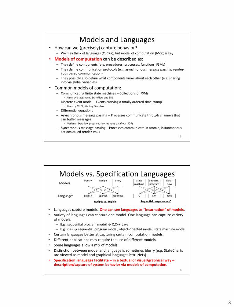
• Languages capture models. One can see languages as “incarnation” of models.
• Variety of languages can capture one model. One language can capture variety of models.– E.g., sequential program model C,C++, Java
– E.g., C++ → sequential program model, object-oriented model, state machine model
• Certain languages better at capturing certain computation models.
• Different applications may require the use of different models.
• Some languages allow a mix of models.
• Distinction between model and language is sometimes blurry (e.g. StateChartsare viewed as model and graphical language; Petri Nets).
• Specification languages facilitate – in a textual or visual/graphical way –description/capture of system behavior via models of computation.
Models
Languages
Recipe
SpanishEnglish Japanese
Poetry Story Sequent.program
C++C Java
Statemachine
Data-flow
Recipes vs. English Sequential programs vs. C

4
7
Communication/
local computations
Shared
memory
Message passing
Synchronous | Asynchronous
Undefined
components
Plain text, use cases
| (Message) sequence charts
Communicating finite
state machines
StateCharts Specification and
Description
Lang. (SDL)
Data flow (Not useful) Kahn networks,
SDF
Petri nets C/E nets, P/T nets, …
Discrete event (DE)
model
VHDL*,
Verilog*,
SystemC*, …
Only experimental systems, e.g.
distributed DE in Ptolemy
Imperative (Von-
Neumann) model
C, C++,
Java
C, C++, Java with libraries
CSP, ADA |
Communication
Co
mp
uta
tio
n
8
• Models of Computation

5
Models of Computation• State-oriented models
– State Transition Diagrams (STD)/ Finite State Machines (FSM)
– Petri Nets (PN)
• Activity oriented models– Data flow graphs (DFG)
• Process-based models
• Kahn Process Networks (KPN)
• Heterogeneous models– Synchronous dataflows (SDF)
• For details on each of the above, see details at:– http://dejazzer.com/ece777/ECE777_3_system_modeling.pptx
9
10
State Transition Diagrams (STD)/Finite State Machine (FSM)
• Help understand the behavioral aspect of the system.
• Simple directed graphs with nodes denoting states & arrows (labeled with triggers & conditions) denoting transitions.
• State: Represents a combination of different input values for a particular moment of time.
• Transitions: Change of state depending on the input received.

6
11
Finite State Machine
• FSM = (Inputs, Outputs, States, InitialState, NextState)
• Often suitable for controllers, protocols etc.
• Rarely suitable for Memory and Datapaths
• Easy to use with powerful algorithms for synthesis and verification
12
Example: Vending machine
ReturnMoney
DeliverSoda, ReturnChange
Idle/StartState
DisplayAmount
DisplayAmountNeeded
MoneyInput
Money notenough
Not enoughMoney
EnoughMoney
CancelCancel
FakeMoney
Power On
Power Off Back to Idle

7
13
Example FSM
• Informal specification:If driver turns on the key and does not fasten seat belt within 5 seconds then sound the alarm for 5 seconds or until driver fastens the seat belt or turns off the key
• Formal representation:Inputs = {KEY_ON, KEY_OFF, BELT_ON, BELT_OFF, 5_SECONDS_UP, 10_SECONDS_UP}
Outputs = {START_TIMER, ALARM_ON, ALARM_OFF}
States = {Off, Wait, Alarm}
Initial State = off
NextState: CurrentState, Inputs -> NextState
e.g. NextState(WAIT, {KEY_OFF}) = OFF
Outs: CurrentState, Inputs -> Outputs
e.g. Outs(OFF, {KEY_ON}) = START_TIMER
14
Limitations
• Scalability - Number of states & transitions increase exponentially as the system complexity increases
• No concurrency support
• Have an unstructured, unrealistic, and chaotic state diagram
• To address these problems Harel proposed StateCharts– Extension of State Transition Diagram/Finite State
Machines

8
• Specification Languages
15
16
Specification Languages• Harel’s StateCharts• UML Statecharts• Statemate• SDL• SystemC• SpecC• VHDL, Verilog, SystemVerilog• Simulink• C, C++, Java• For details on each of the above, see details at:
– http://dejazzer.com/ece777/ECE777_4_specification.pptx

9
Specification language requirements• Hierarchy
– Behavioral and structural
• Compositional behavior– Must be “easy” to derive behavior from behavior of subsystems
• Timing behavior• State-oriented behavior
– Classical automata models are insufficient– Required for reactive systems
• Event-handling– External (caused by the environment) or internal events (caused by the
system)
• No obstacles to the generation of efficient implementations• Support for the design of dependable systems
– Unambiguous semantics and capable of describing security and safety requirements
• Exception-oriented behavior– Not acceptable to describe exceptions for every state
17
• Concurrency
• Synchronization and communication– Concurrent actions have to be able to communicate
• Verifiability
• Presence of programming elements– Programming languages have proven to be convenient for
the expression of computations
– Classical state diagrams do not meet the requirement
• Executability– The possibility to execute a specification is a way for
checking it
• Support for the design of large systems– Software technologies has found object orientation
mechanism for designing large systems18

10
• Domain-specific support– Language feature dedicated to control/data-dominated or
centralized/distributed applications
• Readability– Specification must be readable by the human being
• Portability and flexibility– Small changes of the system’s features should require small
changes to the specification
• Non-functional properties– Fault tolerance, size, expected lifetime, power consumption,
electromagnetic compatibility, extendibility etc.
• Termination• Support for non-standard IO-devices• Appropriate model of computation• It is obvious there will be no formal language meeting all
these requirements. Compromises will have to be made.19
A note on Timing: Problems with classical CS theory and von Neumann computing
• “The lack of timing in the core abstraction is a flaw, from the perspective of embedded software, …”– Ed Lee, Absolutely Positively on Time, IEEE Computer, July 2005.
• “Timing is everything”– Frank Vahid, WESE 2008
• Even the core … notion of “computable” is at odds with the requirements of embedded software– In this notion, useful computation terminates– In embedded software, termination is failure– Subcomputations must terminate with predictable timing
• “What is needed is nearly a reinvention of computer science”– Ed Lee, Absolutely Positively on Time, IEEE Computer, July 2005.
20
11
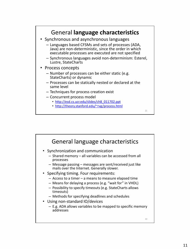
General language characteristics• Synchronous and asynchronous languages
– Languages based CFSMs and sets of processes (ADA, Java) are non-deterministic, since the order in which executable processes are executed are not specified
– Synchronous languages avoid non-determinism: Esterel, Lustre, StateCharts
• Process concepts– Number of processes can be either static (e.g.
StateCharts) or dynamic– Processes can be statically nested or declared at the
same level– Techniques for process creation exist– Concurrent process model
• http://esd.cs.ucr.edu/slides/ch8_011702.ppt• http://theory.stanford.edu/~rvg/process.html
21
General language characteristics
• Synchronization and communication– Shared memory – all variables can be accessed from all
processes– Message passing – messages are sent/received just like
mails over the Internet. Generally slower.
• Specifying timing. Four requirements:– Access to a timer – a means to measure elapsed time– Means for delaying a process (e.g. “wait for” in VHDL)– Possibility to specify timeouts (e.g. StateCharts allows
timeouts)– Methods for specifying deadlines and schedules
• Using non-standard IO/devices– E.g. ADA allows variables to be mapped to specific memory
addresses
22

12
23
Overview
• Harel’s StateCharts• UML Statecharts• Statemate• SDL• SystemC• SpecC• VHDL, Verilog, SystemVerilog• Simulink• C, C++, Java
Harel Statecharts• Introduced by David Harel in 1987 - provide compact and
expressive visual formalisms for reactive systems.• What are Statecharts?
– Viewed as both model and graphical specification language.– Describe communicating finite state machines - Visual formalism for
describing states & transitions in modular fashion.
• What is the purpose of using Statecharts?– To suppress and organize detail. – Best if graphical. The clarity they provide can be lost if they are
represented in tabular form. – Allows the super states to have history. History is helpful for back-
up, if system fails.
• The Harel statechart is equivalent to a state diagram but it improves the readability of the resulting diagram.
• It can be used to describe many systems, from computer programs to business processes.
24

13
Harel Statecharts• They are directed graphs and used to describe the
behaviour of an object. The vertices are the states an object can reach. Edges are changes of the state, the so-called transitions.
• Statecharts based on a generalization of the concepts of FSMs. It’s considered that the computing power of statecharts is the same as that of Finite State Machines.
• Recent paper argues that the computation power of statecharts is far beyond that of Finite Automata and that Interaction Machines are the most accurate theoretical models for statecharts
• Used as a modeling tool and adopted by Unified Modeling Language (UML) as an important technique to model the dynamic behavior of systems.
25
26
State-Transition Diagram vs. Statechart
S
T
U
E
G/A
F
FG/A E/B
State-transition diagram
G/A E/ B
S
T
U
E
F
G/A
Statechart
F
• The statechart reduces the number of transitions when compared to STD.• G/A represents that for event G action A takes place.• S & T are combined together into a super-state F (OR- property of the
statechart)

14
State-Transition Diagram vs. Statechart
27
Property State-transition
Diagram
Statechart
Super-states Absent Present
History Absent Present
Concurrency Absent Present
Broadcast
Communication
Absent Present
Synchronization &
Timing Info
Absent Present
Hierarchical
Structure
Absent Present
Statecharts development
• 2 Types of statechart development
– Harel Statecharts
• Developed by David Harel.
• First developed for function-oriented systems.
• Later extended for OO systems with few changes.
– UML Statecharts
• Developed by Object Management Group (OMG).
• Extended the properties of Harel statecharts with some new features.
28

15
Example: Harel Statechart
• Harel Statechart showing properties of orthogonality, and-decomposition, History, Clustering, Refinement, Forking issues.
• E/A -Represents that for event E, action A will take place.
• Dashed line represents the AND-product (orthogonality) of states R & T.
• F[in(Y)]: The function in [] (i.e. in(Y)) represents the guard condition.29
U
V
X
Y
W
A
H
G K
E
J
F[ in (Y)]E
R T E1/ A1
E2/A2
Example: Equivalent STD
• If there are n states in one side of the dashed line in a super-state and m states in the other side, then the total number of maximum states in the equivalent state-transition diagram will be the product m*n.
30
U_X
V_Y
U_Y
V_W
U_W
V_X
A
A
G
G
J
E
K
FE
K
E
E

16
1. Decomposition: OR-State, AND-state
• A superstate may be decomposed into any number of OR-states. When the object is in the superstate, it must be in exactly one of its OR-substates.
• S is decomposed into X & Y. At any given time S will be either in X or Y but not both.
• The default start state in S is X. t1 & t0 are the events depending on which the S will be in either X or Y
31
X
Y
t1 t0
S
OR State
• A superstate may be decomposed into any number of AND-states. When the object is in the superstate, it must be in every active AND-substates (shown with dashed lines).
• C is the superstate formed by the AND product of A & B.
• X & R are the default initial states of A & B respectively. When the system enters C it will be present in both X & R at the concurrent time.
Z
S
R
Y
X
t6t0 t1
t3A
t1
AND State
B
C
2. Clustering & Refinement• Clustering is a bottom-up concept & refinement is a top-down one; both
give rise to the OR-relationship between a state’s sub-states.• Reduces the number of transitions in a statechart. • Superstate R & T can be extended if needed in order to view the sub-
states and their internal transitions, which is called refinement.
32
S
T
UU
G/A
E
F
G/A E/B
F
E
F
G/A
S
T
G/A E/B
Simple State Diagram Clustering of States
A
• States S & T are clustered into a single super-state A.• Expanding A & showing its sub-states is refinement.

17
3. History
• History (H), in a statechart gives the most recently visited state of the super-state that it is entering.
• Shallow History (H): Represents the most recently entered state at the same level.
• Deep History (H*): Represents entering the most recently visited state irrespective of how deep the state is.
• History is “forgotten” if dead has been entered in the meantime.
33
• H – History chooses between G & F. H remembers between A,B,C,D,E.
• H remembers the last sub-state (both history and sub-states should be at the same level) the system left.
• H* - System will enter the most recently visited state (A-E)
• H* remembers the last sub-state the system left, irrespective of how deep it may be when considered with the history state.
• B & C are the default initial states for G & F.
34
H/H*
A
B
C
E
D
G
K
F

18
4. Orthogonality5. Overlapping states
35
• Orthogonality– Reduces the number of states.– Viewed as the AND product of two states (consisting of sub-
states) which gives a certain kind of synchronization.– Generalization of the usual product of automata with some
dependence between components (like common events or conditions).
• Overlapping states– A state which is present in both the super-states. – Overlapping states removes redundancy.– Turns XORs state machine into ORs.– Causes semantic problems especially when the overlapping
involves orthogonal components.
• Sub-state “C” is present in both A & D, i.e. the relation between A & D is OR.
• Too much of overlapping should be avoided as it leads to unnecessary burden & complexity.
36
B
A
CE
F
D
a
b

19
6. Delays & Timeouts (event, number)
• Represents the event that occurs precisely when the specified number of time units has elapsed from the occurrence of the specified event.
• Has lower bound and upper bound attached to each of the timeouts and events.
• Lower Bound: If events are to cause exits, events do not apply in the state until the lower bound is reached.
• Upper Bound: The event has to take place in that time.
37
7. Conditions & Selection Entrances (C & S)
• Condition (C): Upon the entrance of the super-state a condition is checked and the transition is made to one of the sub-states in the super-state.
• Selection (S): The transition is made depending on a generic value of the input rather than the condition.
38

20
Conditions & Selection Entrances (C & S)
• C represents the conditions.• The state entered depends on whether C
evaluates to P, Q or R and states reached will be Z, X, Y respectively.
• On entering the super-state, which state (whether X,Y,Z) to enter depends on the what the condition C evaluates to.
39
aY
X Z
CR
PQ
• The decision to enter one of the three states, A, B, C depends on what will be the generic value of S.
A
C
B
S
Data Entered
ResetExecute
Set_up
More properties
40
8. Harel statechart is a mix of Mealy and Moore state machines and flowchart.
9. Fork & merge (see figure).
10. Broadcast feature in statecharts.
A
B C
D E
F
E1/A1
E2/A2

21
Shortcomings of Harel Statecharts• Semantics: How to represent?
– No specified approach.– Many papers published, each having one flaw or other, none giving the
complete formal semantics.– Harel introduced STATEMATE CASE tool to deal with this but that paper too
had one debatable topic.
• Notion of time– Assumption: Transitions take zero time (not possible for RT systems).– No way to tell whether how long the system can stay in a particular state.
• Determinism– What should be done in case an event may result in multiple transitions
each leading to a different state?– Which one of the transitions must have precedence over others?– Leads to non-deterministic situation.
• Race condition: What will be the resulting value?– Non-determinism of statechart may result in race condition for the system.– Multiple transitions on multiple states may occur for the same event, and
may attempt to modify the same value.
41
Shortcomings: non-determinism• Priority should be given to transitions so as to eliminate the non-determinism.
• On entry into the superstate S, both the sub-states are traversed concurrently.
• When the system exits S, it is not sure what the values of X & Y will be, it depends on which one of the events triggered first (i.e., if E in S1 is triggered first then the values of X and Y both will be 1, else X will be assigned to 1 and the value of Y depends what X was prior to being assigned 1).
• This leads to non-determinism in the system.
42
S11
S12 S22
S21
E/X=1 E/Y=X
S1 S2
S

22
Shortcomings: race condition• Race Situation: What is the value of X after state “S” is
exited?• There is race condition in the system. The value of X
depends on which of the events i.e. E in S1 or E in S2 triggered last.
43
S11
S12 S22
S21
E/X=1 E/X=2
S1 S2
S
Shortcomings of Harel Statecharts
• Infinite loops:
– Doesn’t define the property of consistency check in its model.
– The flaw in the design may lead to infinite loop while the system is being designed.
• Inconsistency in free transitions:
– Inconsistency when an exit transition leaving a composite boundary happens to be an unlabelled transition.
• Statecharts do not support any dynamic semantics to cover their precise behavioral aspects.
44

23
Conclusion
• StateCharts’ main application domain is that of local, control-dominated systems.
• Key advantage is the property of nesting hierarchies.
• Examples of tools based on StateCharts: StateMate (IBM), StateFlow (MathWorks), BetterState (WindRiver, Intel). Many can translate StateCharts into equivalent C or VHDL, from which hardware can be synthesized.
45
Further info
• http://ls12-www.cs.tu-dortmund.de/daes/media/documents/staff/marwedel/es-book/slides10/es-marw-2.02-fsm.ppt
• http://www-inst.eecs.berkeley.edu/~ee249/fa08/Lectures/mocFSM-CFSM.pdf
46

24
Overview
• Harel’s StateCharts• UML Statecharts• Statemate• SDL• SystemC• SpecC• VHDL, Verilog, SystemVerilog• Simulink• C, C++, Java
47
Basic UML Statechart Diagram
48

25
UML (unified modeling language) statecharts
• Harel statecharts are the basis for UML statecharts.
• Harel statecharts were mainly designed for function-oriented structured analysis design techniques, later extended for OO technology.
• Statecharts were introduced in UML with modifications in the semantics and some in-build terminology.
49
Example
• UML statechart showing properties of orthogoanlity, and-decomposition, History, Clustering, Refinement, Forking issues, pseudostates, Synch pseudostates.
50
G
C1
D2D1
C2
B
A
D3
E1/A1
E2/A2
F
F

26
UML Statecharts: Properties1. Object Behavior:
– An object can be in different states depending on the present value of the variables and data types it has.
– The object behavior can be represented in three different types:
1. Simple behavior: Doesn’t depend on history of the previous inputs or services. E.g. simple mathematical functions.
2. State behavior: The entire system or space is divided into states.
3. Continuous behavior: Depends on object’s time history.
2. Delays & Timeouts:
– Statechart transitions are modeled to take insignificant amount of time.
– A guard and a trigger represent a transition. They are of two types of triggers:• Named Trigger: Results in transition.
• Null transition: Evaluated only once upon entrance to the source state.
– Assumption: Evaluation of conditions, guards and triggers takes zero amount of time.
– Timeouts are there in UML statecharts.51
UML Statecharts: Properties3. UML statecharts define 4 types of events:
– Signal: Event due to extended asynchronous process.– Call: Execution of an operation within the object.– Change: Change in value of an attribute.– Time: Lapse of a time-interval.
4. Message passing between different diagrams5. Priority given to transitions with the innermost source state.
52
A
B
B1
Enter: f(a)Exit: g()
Enter: x()Exit: y(a, b)
First y(a, b)then g()
First f(a) is then x()
Execute from outermost first – for entryExecute from innermost first – for exit

27
UML Statecharts: Properties6. Actions and Activities:
– Activities: Performed as long as the state is active, interpreted and terminated by the receipt of an incoming event.
– Actions: Usually short, non-interruptible behavior while activities longer, interruptible behavior.
7. Fork & Join in UML.8. Two different kinds of state machine formalisms:
– Statechart Diagrams: Used when state transitions takes place when an event of interest occurs.– Activity diagrams: Changes state primarily upon completion of the activities executed.
9. UML statecharts have some dependence on abstract state machines along with Mealy’s. Harel statecharts are mainly based on Moore’s
10. Events can carry parameter, which Harel’s statechart doesn’t support.11. Conditional guards.12. Guards & explicit state machines.
53
Off On
OnButtonPushed [Guard Condition] / Action:= Start();ControlPanel.UpdateState(Start)
Message: OnButtonPushedGuard: Guard ConditionAction: Start() [Internal Action]ControlPanel.UpdateState(Start) [External Action]
UML Statecharts: Properties13. Pseudostates.
– A kind of state vertex in the UML metamodel that represent transient points in transition paths within a state machine.
– Vertical bars indicate where concurrent behavior begins or ends (called pseudostates)
– E.g. Start state, Terminal state, Connectors etc.
14. Synch Pseudostate
– Allows a special kind of guard in which a “latch” remembers that a specific transition has occurred
– Similar to Petri net “place” with explicitly indicated capacity
– Must synchronize across AND-States
54
G
C1
D2D1
C2
B
A
D3
E1/A1
E2/A2
F
FC
Synch Pseudostate
Pseudostates

28
Symbols
55
Join
Fork
Synch
Terminal
Branch
Pseudostate Name
Symbol
C OR
T OR
* OR n
Stub
Merge Junction
Choice Point
Junction
Initial/Default
Deep History
Shallow History
Pseudostate Name
Symbol
H
H*
Shortcomings of UML statecharts1. No discussion of extension mechanisms of statechart
diagrams.2. Do not support overlapped states:
– But the same functionality can be achieved without the use of overlapped states, though overhead involved to design it increases.
3. Boundary crossing violates encapsulation:– Boundary crossing (supported by UML) is the practice, which violates the
encapsulation of hierarchical states machines.
4. Non-determinism:– UML’s reversed priority rule for resolving inter-level concurrency conflicts
introduces non-determinism in the outer state machine.
5. Representation of states:– UML statecharts can properly represent only one distinct accept state in a
sub-state machine.
6. Exit Paths:– In UML all the exit paths are subsequently merged in the single completion
transition leaving the composite state boundary.56

29
Example: Mobile Phone System
57
Dial
Call
Talk
MSC Server Idle
Assigning
ReadyReady
RegularCall
Idle
Receive Call[Regular Call]
BS Server ActiveBS Server Idle
Start
Shut DownReceive a call[Correct #]
MSC Server ActiveStart
Shut Down
Hang Up
Power ON [Simulation]
[MSC Server Shutdown]
[Wrong #]Send Frame
ReceiveIP & Portsuccessfully
Dial Digit (n)[Valid]
Dial Digit (n)[Incomplete]
[BS Server Shutdown or in saturation of capacity]
Active
Send a Call
Connect
Comparison
58
Property Harel Statechart UML Statechart
Nesting & Orthogonal Regions Supported Supported
Single transition represents the same
event from different sub-states
Supported Supported
Broadcast events. Supported Supported
History Supported Supported
Sub-machines Supported Supported
Overlapping states Supported Absent
Pseudostates Absent, but connectors perform
same operations
Supported
Fork & Join methodology Fork and Merge Implemented using
pseudostates.
Event carrying feature Absent Supported
Free transitions Inconsistency when an exit
transition leaving composite
boundary
Prevented in UML by defining
a free boundary exit transition
Synchronization Limited # of ways: IS_IN
parameter, Broadcast
Communication
# of ways: Broadcast
Communication, Fork, Join,
Propagated events, IS_IN
operator, synch pseudostate
Event Handling Outermost state machine Innermost state machine.

30
Conclusion
• MoC: FSM + shared memory
• Use of Harel statecharts or UML statechartsdepends on the requirements for the design of the system.
• Systems which have synchronization as their main issue can be well-designed if they used UML statecharts.
• UML statecharts are widely used due to popularity, & number of tools in market that support UML statecharts.
59
Further Info• http://en.wikipedia.org/wiki/UML_state_machine
• http://www.uml.org
• Practical UML - A Hands-On Introduction for Developers:
– http://edn.embarcadero.com/article/31863
• Miro Samek (2008). Practical UML Statecharts in C/C++, Second Edition: Event-Driven Programming for Embedded Systems. Newnes. ISBN 978-0-7506-8706-5.
60