Embed Size (px)
Citation preview
ORIGINAL RESEARCH
Coconut oil-cellulose beaded microfibers by coaxialelectrospinning: An eco-model system to studythermoregulation of confined phase change materials
W. M. Ranodhi N. Udangawa . Charles F. Willard . Chiara Mancinelli .
Caitlyn Chapman . Robert J. Linhardt . Trevor John Simmons
Received: 18 August 2018 / Accepted: 22 November 2018 / Published online: 4 December 2018
© Springer Nature B.V. 2018
Abstract Coconut oil was used to produce biomass
microfibers with a coconut oil core and a cellulose
shell by a co-axial electrospinning technique. This
novel material was developed as a model system to
determine the effect of confining a phase changing
material within an axial micropore of a coaxial fiber.
The morphology of these composite fibers was
determined by scanning electron microscopy and
transmission electron microscopy, which revealed a
unique beaded necklace morphology with sub-micron
scale pockets of confined coconut oil. Thermogravi-
metric analysis and differential scanning calorimetry
were employed to study the thermal behavior of the
composite fibers. A significant increase of the specific
heat capacity (+98%) was observed when the
coconut oil was confined within the micropore of
the composite fiber compared to the bulk. There was
also a notable increase (+41%) of the specific heat of
melting for the micropore confined coconut oil. Thus,
coconut oil isolated in the axial micropore core of
these cellulose composite fibers showed excellent
potential for temperature regulation in the range of 7
to 22 °C, which includes 21 °C, the temperature
which most humans find comfortable. The results of
the studied model system can be used to tailor the
properties of phase change materials in confined
micropores, in both electrospun fibers and other
mesoscale structures.
Electronic supplementary material The onlineversion of this article (https://doi.org/10.1007/s10570-018-2151-2) contains supplementary material, whichis available to authorized users.
W. M. R. N. Udangawa (&) · C. Mancinelli ·
C. Chapman · R. J. Linhardt
Department of Chemistry and Chemical Biology,
Rensselaer Polytechnic Institute, Troy, NY 12180-3590,
USA
e-mail: [email protected]
W. M. R. N. Udangawa · R. J. Linhardt
Center for Biotechnology and Interdisciplinary Studies,
Rensselaer Polytechnic Institute, Troy, NY 12180-3590,
USA
C. F. Willard · R. J. Linhardt
Department of Chemical and Biological Engineering,
Rensselaer Polytechnic Institute, Troy, NY 12180-3590,
USA
R. J. Linhardt
Rensselaer Nanotechnology Center, Rensselaer
Polytechnic Institute, Troy, NY 12180-3590, USA
R. J. Linhardt · T. J. Simmons
Heparin Applied Research Center, Rensselaer Polytechnic
Institute, Troy, NY 12180-3590, USA
123
Cellulose (2019) 26:1855–1868
https://doi.org/10.1007/s10570-018-2151-2(0123456789().,-volV)(0123456789().,-volV)
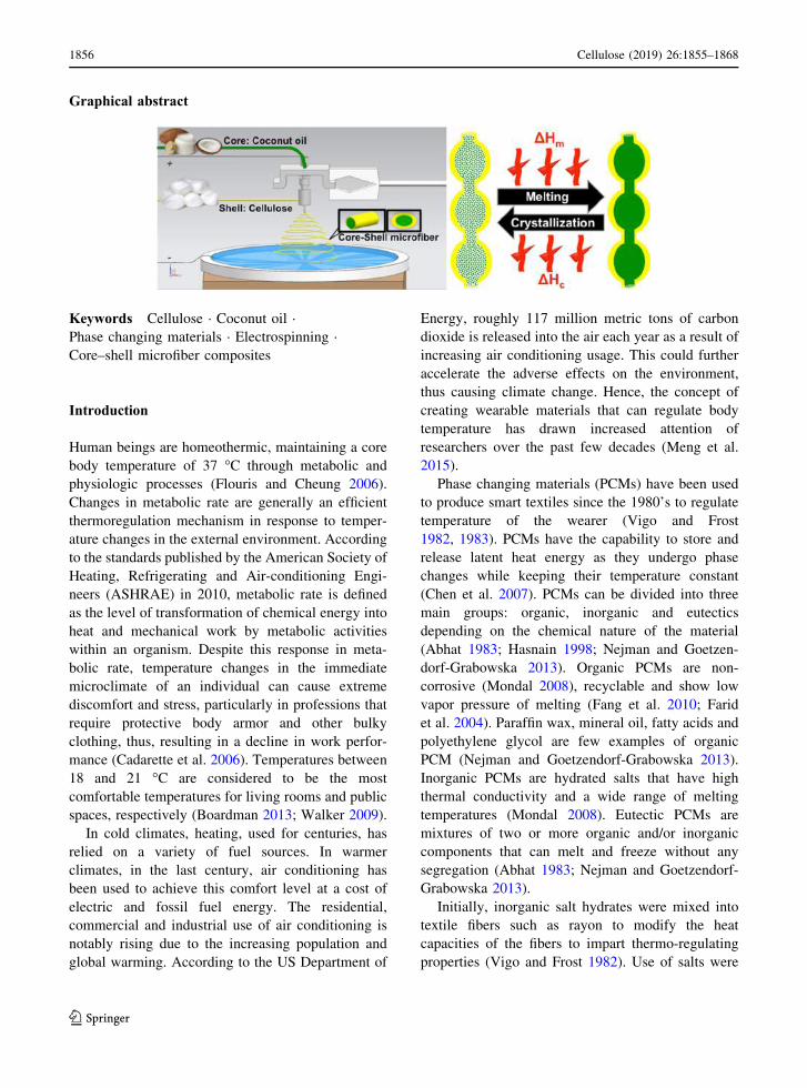
Graphical abstract
Keywords Cellulose · Coconut oil ·
Phase changing materials · Electrospinning ·
Core–shell microfiber composites
Introduction
Human beings are homeothermic, maintaining a core
body temperature of 37 °C through metabolic and
physiologic processes (Flouris and Cheung 2006).
Changes in metabolic rate are generally an efficient
thermoregulation mechanism in response to temper-
ature changes in the external environment. According
to the standards published by the American Society of
Heating, Refrigerating and Air-conditioning Engi-
neers (ASHRAE) in 2010, metabolic rate is defined
as the level of transformation of chemical energy into
heat and mechanical work by metabolic activities
within an organism. Despite this response in meta-
bolic rate, temperature changes in the immediate
microclimate of an individual can cause extreme
discomfort and stress, particularly in professions that
require protective body armor and other bulky
clothing, thus, resulting in a decline in work perfor-
mance (Cadarette et al. 2006). Temperatures between
18 and 21 °C are considered to be the most
comfortable temperatures for living rooms and public
spaces, respectively (Boardman 2013; Walker 2009).
In cold climates, heating, used for centuries, has
relied on a variety of fuel sources. In warmer
climates, in the last century, air conditioning has
been used to achieve this comfort level at a cost of
electric and fossil fuel energy. The residential,
commercial and industrial use of air conditioning is
notably rising due to the increasing population and
global warming. According to the US Department of
Energy, roughly 117 million metric tons of carbon
dioxide is released into the air each year as a result of
increasing air conditioning usage. This could further
accelerate the adverse effects on the environment,
thus causing climate change. Hence, the concept of
creating wearable materials that can regulate body
temperature has drawn increased attention of
researchers over the past few decades (Meng et al.
2015).
Phase changing materials (PCMs) have been used
to produce smart textiles since the 1980’s to regulate
temperature of the wearer (Vigo and Frost
1982, 1983). PCMs have the capability to store and
release latent heat energy as they undergo phase
changes while keeping their temperature constant
(Chen et al. 2007). PCMs can be divided into three
main groups: organic, inorganic and eutectics
depending on the chemical nature of the material
(Abhat 1983; Hasnain 1998; Nejman and Goetzen-
dorf-Grabowska 2013). Organic PCMs are non-
corrosive (Mondal 2008), recyclable and show low
vapor pressure of melting (Fang et al. 2010; Farid
et al. 2004). Paraffin wax, mineral oil, fatty acids and
polyethylene glycol are few examples of organic
PCM (Nejman and Goetzendorf-Grabowska 2013).
Inorganic PCMs are hydrated salts that have high
thermal conductivity and a wide range of melting
temperatures (Mondal 2008). Eutectic PCMs are
mixtures of two or more organic and/or inorganic
components that can melt and freeze without any
segregation (Abhat 1983; Nejman and Goetzendorf-
Grabowska 2013).
Initially, inorganic salt hydrates were mixed into
textile fibers such as rayon to modify the heat
capacities of the fibers to impart thermo-regulating
properties (Vigo and Frost 1982). Use of salts were
1856 Cellulose (2019) 26:1855–1868
123
subsequently replaced with polymeric materials to
produce more durable composite fibers (Vigo and
Frost 1983). Several types of polymeric nanocom-
posite fibers have been fabricated by electrospinning
(Chen et al. 2007, 2011), in which one polymer is
used as the matrix and the other functions as a PCM.
Even though general mixing of PCMs with other
polymers works for the most part (Chen et al. 2007),
encapsulation of the PCMs inside polymers prevents
leaching of the PCMs, thereby ensuring the durability
of the material. Outlast Technologies, one major
provider of phase change fabrics, recently introduced
a thermo-regulating textile fiber-composite consisting
of textile yarns injected with microencapsulated
PCMs called Thermocules® (Coyle et al. 2007; Iqbal
and Sun 2014; Nelson 2002).
Electrospinning is a fiber fabrication technique
that was invented nearly a century ago (Cooley
1902). Conventional electrospinning involves disso-
lution of the desired polymer in a volatile solvent that
evaporates in the electrospinning process leaving dry
polymeric fibers on a solid collector, commonly
known as wet-dry electrospinning (Chen et al. 2010;
Hou et al. 2016; Lalia et al. 2013). Electrospinning
complex polysaccharides, such as cellulose, is chal-
lenging due to the insolubility of cellulose in water or
most volatile organic solvents (Meli et al. 2010).
Cellulose, a linear polysaccharide with an extensive
hydrogen-bonding network, possesses excellent ther-
mal and mechanical properties allowing it to form
fibers with high tensile strength (Hou et al. 2016;
Khalil et al. 2012). While its strong intra and inter-
molecular hydrogen-bonding prevents the dissolution
of cellulose in conventional solvents (Liebert 2010), a
class of non-volatile, hydrogen-bond-breaking sol-
vents known commonly as room temperature ionic
liquids (RTILs) readily dissolve cellulose and can be
used in electrospinning (Farran et al. 2015; Meli et al.
2010; Simmons et al. 2011; Viswanathan et al. 2006).
RTIL-dissolved cellulose can be electrospun into a
coagulation bath filled with water, a non-solvent that
is miscible with the RTIL but which does not dissolve
cellulose. This process is referred to as wet–wet
electrospinning (Freire et al. 2011; Meli et al. 2010;
Miao et al. 2011; Teo and Ramakrishna 2006; Zheng
et al. 2014).
Our goal is to develop a one-step process to
inexpensively encapsulate biocompatible PCM inside
a cellulose matrix that can be adapted to a wide
variety of ‘green’ polymers. Electrospinning is
selected because of its widespread use in fabricating
polymeric composites in industry. We hypothesize
that confining coconut oil in the core of a cellulose
fiber could result in a robust phase change material
and could produce a beneficial impact on the thermal
properties of the coconut oil through confinement.
In the current study, hollow cellulose microfibers
are used as a solid supporting sheath to hold coconut
oil, which acts as the phase changing material. These
novel electrospun composite fibers are created by the
wet–wet/melt/co-axial electrospinning (McCann
et al. 2006) method. Cellulose is the most abundant
biopolymer on earth (Arioli et al. 1998; Swatloski
et al. 2002) making this composite both inexpensive
and biodegradable (Frenot et al. 2007). Co-axial
electrospinning isolates coconut oil in the microfiber
core surrounded by a cellulose shell (Huang et al.
2015; Lan et al. 2015; Yu et al. 2013a, b). Multi-axial
electrospinning techniques require multi-nozzle spin-
nerets that allow fabrication of fibers with multiple
materials in contrast to mono-axial electrospinning
(Li et al. 2010).
Coconut oil is an inexpensive and sustainable
natural alternative to other more expensive PCMs
such as inorganic salts (Vigo and Frost 1982) and
synthetic polymers (Vigo and Frost 1983). It is
extracted from the kernel/meat of mature coconut
harvested from the coconut palm tree, Cocosnucifera, and consists of a mixture of saturated fatty
acids (51% is lauric acid) (Jayadas and Nair 2006). In
contrast to most vegetable oils, coconut oil has a pour
point as high as 24 °C (Ajithkumar et al. 2009). It is
an edible oil with many health benefits and a wide
range of applications in food, cosmetics, lubricants,
and biodiesel industries (Jaganathan and Fauzi Ismail
2017).
Our composite fibers are composed of inexpen-
sive, environmentally friendly, and biodegradable
materials. The fibers themselves are sustainable
because cellulose is highly abundant and coconut
trees grow in many parts of the world. These trees can
be replanted and therefore are a sustainable option.
The fibers are a sustainable energy conversion source
as an alternative to electrical appliances such as air
conditioning, etc. While phase changing materials are
reported in literature that involves expensive materi-
als and synthetic routes (Chen et al. 2007; Fang et al.
2010; Fang and Zhang 2006; Fang et al. 2008; Meng
Cellulose (2019) 26:1855–1868 1857
123
et al. 2015; Nelson 2002; Zhang et al. 2007), our
smart composite fibrous material represents a sus-
tainable alternative with a potential of being used in a
broad range of applications such as smart textiles and
other thermal insulation products.
Experimental section
Materials
Bleached high-pure sulfite spruce (softwood) cellu-
lose pulp (SFI) with 95% α-cellulose content and 2%
alkali-soluble content (degree of cellulose polymer-
ization approx. 1100) was obtained from
Weyerhaeuser Co. (2449 Stagecoach Rd, Oglethorpe,
GA 31068 U.S.A). The RTIL 1-ethyl-3-methylimi-
dazolium acetate ([EMIM][Ac]), absolute ethanol (≥99.8%) and analytical grade coconut oil were
obtained from Sigma-Aldrich (St. Louis, Missouri,
U.S.A). Double-distilled water (ddH2O) was used for
all the electrospinning experiments and subsequent
washing steps.
Preparation of the fibers
Preparation of polymer solutions for electrospinning
Cellulose pulp was dissolved in [EMIM][Ac] by
mechanical stirring at 80 °C to prepare a 1.5% (w/v)
homogenous cellulose solution. Solidified coconut oil
was melted by heating at 100 °C for 5 min.
Electrospinning procedure
The wet–wet electrospinning technique was used to
construct the microfibers. All the electrospinning
experiments were conducted inside an anti-static
polycarbonate box designed and constructed in our
lab. The CAD (Computer-aided design and drafting)
model of the electrospinning box is shown in Fig. 1a.
The entire electrospinning process was carried out in
this box within a standard laboratory fume hood. All
the experiments were carried out at 20±3 °C with a
relative humidity of 48±5%. The temperature and
the relative humidity were measured using a digital
humidity and temperature monitor (AcuRite®). After
a comprehensive literature review, the initial electro-
spinning parameters were selected from the following
ranges: concentration of cellulose from 1.5 to 2 w/v%
(Hou et al. 2016; Miao et al. 2011; Miyauchi et al.
2010, 2011; Quan et al. 2010; Zheng et al. 2014);
voltages from 15 to 20 kV (Hou et al. 2016; Liu and
Hsieh 2002; Miao et al. 2011; Zheng et al.
2014, 2016); cellulose flow rate of 40 µL/min (Hou
et al. 2016; Zheng et al. 2016); and distance of 9 cm
(Miao et al. 2011; Miyauchi et al. 2010, 2011; Zheng
et al. 2014, 2016). There is no reference for the flow
rate of coconut oil since it has never been previously
electrospun. There is an element of trial and error to
finding optimal parameters for any specific electro-
spinning study (Quan et al. 2010; Vatankhah et al.
2014). The initial parameters were then optimized for
this particular study to be: 1.5 w/v% concentration of
cellulose; 18 kV voltage; 80 µL/min flow rate of
cellulose; 10 µL/min flow rate of coconut oil; and
12.7 cm distance between the tip of the needle and
the surface of the coagulation bath.
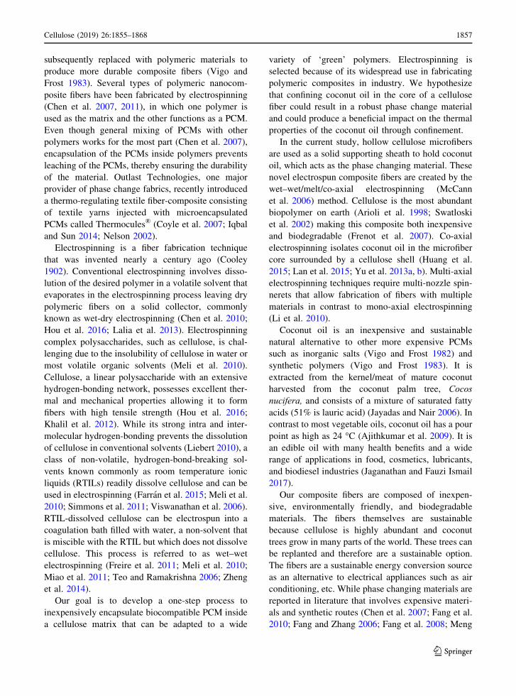
The coconut oil-cellulose core–shell microfibers
were fabricated using the coaxial electrospinning
technique. The schematic of the co-axial electrospin-
ning apparatus is shown in Fig. 1b. A co-axial
spinneret (MECC, Ogori, Fukuoka, Japan) was fitted
with a blunt tip aluminum needle (23 Gauge) that has
an internal diameter of 0.635 mm. The diameter of
the outer needle was 2.50 mm. The 1.5% (w/v)
cellulose solution (shell solution) and melted coconut
oil (core solution) were placed in two separate 10 mL
Norm-Ject syringes and connected to the spinneret
using polytetrafluoroethylene (PTFE) tubing. A
syringe heater kit (HEATER-KIT-1, New Era Pump
System Inc., Wantagh, New York, U.S.A) was used
to keep the melted coconut oil at a constant
temperature of 80 °C. A high-voltage of 18 kV was
applied between the spinneret (positive) and the
electrically grounded collector (negative) using a
high voltage supply (CZE1000R, Spellman, Haup-
pauge, New York, U.S.A) that is capable of
generating a DC voltage up to 30 kV. The collector
was a coagulation bath filled with 50% ethanol–water
mixture with a small sheet of aluminum foil on the
bottom. Pure ethanol and other highly flammable
solvent baths must be avoided due to the risk of fire,
as the frequent arcing is a source of ignition.
Electrospun fibers were collected after the removal
of the [EMIM][Ac] in the coagulation bath, which
coagulated and solidified the fibers. The distance
between the needle tip and the surface of the solution
1858 Cellulose (2019) 26:1855–1868
123
in the coagulation bath (spinning distance) was fixed
at 12.7 cm. Two syringe pumps (NE-1000, New Era
Pump System Inc., Wantagh, New York, U.S.A) were
used to feed the core and shell polymer solutions at
constant rates of 10 μL/min and 80 μL/min, respec-
tively, to obtain continuous core–shell composite
fibers. Finally, the fibers were washed several times
with distilled and deionized water, and freeze-dried to
obtain the final coconut oil-cellulose core–shell
composite fiber balls.
Mono-axial electrospinning was used to fabricate
cellulose microfibers as the negative control. The
1.5% (w/v) cellulose solution was placed in a 10 mL
Norm-Ject syringe and connected to the mono-axial
spinneret (MECC, Ogori, Fukuoka, Japan) using
PTFE tubing. The spinneret was fitted with a blunt
tip aluminum needle (23 Gauge) with an internal
diameter of 0.635 mm. A high-voltage of 18 kV was
applied while keeping the spinning distance fixed at
12.7 cm. The cellulose solution was pumped at a
constant rate of 40 μL/min to obtain continuous
monofilament fibers. Finally, the fibers were washed
several times with water and freeze-dried to obtain
the final cellulose microfiber balls.
Characterization
The amount of coconut oil inside the composite fibers
was determined by crushing a known weight of fibers
in hexane. This process forced the coconut oil to
come out and get dissolved in hexane. Hexane was
later evaporated and the mass of coconut oil was
obtained. The mass of composite fibers before the
extraction and after corroborated the results. Carl
Zeiss supra field emission scanning electron micro-
scope (FESEM, Hillsboro, USA) was used to image
the electrospun fiber samples at 1.5 kV (Resolution at
1 kV–2.5 nm). The average fiber diameters were
determined from SEM images of over 200 individual
fibers across 10 identical electrospinning experiments
(Supporting Figure S1 & S2), using NIH Image J
software (National Institute of Health, MD, USA).
The core–shell fiber samples were further character-
ized using transmission electron microscopy (TEM).
The samples were dispersed in ethanol, deposited on
lacey carbon coated 200 mesh copper grids, and
imaged at an accelerating voltage of 200 kV using the
JEOL-JEM-2011 TEM (JEOL Ltd., Tokyo, Japan).
The images were analyzed using NIH Image J
software (National Institute of Health, MD, USA).
Histograms representing the fiber size distribution
were prepared using the Microsoft Excel™ software.
Cellulose microfibers, coconut oil and coconut oil-
cellulose core–shell composite fiber samples were
subjected to thermogravimetric analysis (TGA) and
differential scanning calorimetry (DSC). A computer-
controlled TA Instruments TGA-Q50 apparatus (New
Castle, Delaware, USA) was used to heat samples
from room temperature to 800 °C at a constant
heating rate of 5 °C/min under dry atmospheric
conditions. Pre-weighed samples were sealed in
hermetic aluminum pans and subjected to three
Fig. 1 Electrospinning set up. a Antistatic polycarbonate box, b Co-axial electrospinning set up
Cellulose (2019) 26:1855–1868 1859
123
heating and cooling cycles between 0 and 45 °C at a
constant heating rate of 1 °C/min. TA Instruments
DSC-Q100 apparatus (New Castle, Delaware, USA)
was used for this analysis.
Results and discussion
The wet–wet electrospinning technique was used to
make cellulose and cellulose-coconut oil microfibers.
An anti-static polycarbonate box was designed and
constructed to isolate the electrospinning process
from interference from static charges and the draft of
the fume hood (Fig. 1a). Small ventilation windows
were incorporated to accommodate solvent evapora-
tion thereby keeping the humidity inside the box at
48±5% throughout the electrospinning process. The
co-axial electrospinning process used to fabricate
coconut oil-cellulose core–shell microcomposite
fibers is shown in Fig. 1b.
Initially, the cellulose-[EMIM][Ac] fiber jet forms
an intermediate hydrogel upon entering the coagula-
tion bath. This hydrogel state was formed due to the
migration of RTIL into the water bath in exchange for
water molecules (Hou et al. 2016). This process
enables efficient removal of ionic liquid from the
fiber. All the fibers collected in the coagulation bath
were washed several times with distilled water and
water/ethanol mixture under suction filtration to
remove residual ionic liquid and other possible
contaminants (Mahadeva and Kim 2012). During
the washing steps fibers swell as expected to ensure
effective removal of ionic liquid. Finally, the fibers
were freeze-dried to obtain dry nonwoven microfiber
mats. Freeze-drying was preferred over air-drying to
obtain a structure similar to cotton balls (Si et al.
2014; Zheng et al. 2016). The amount of coconut oil
inside the composite fibers was determined to be
around 76±10% based on the total mass of the
composite fibers.
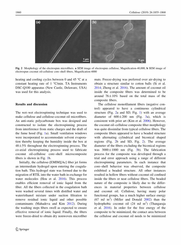
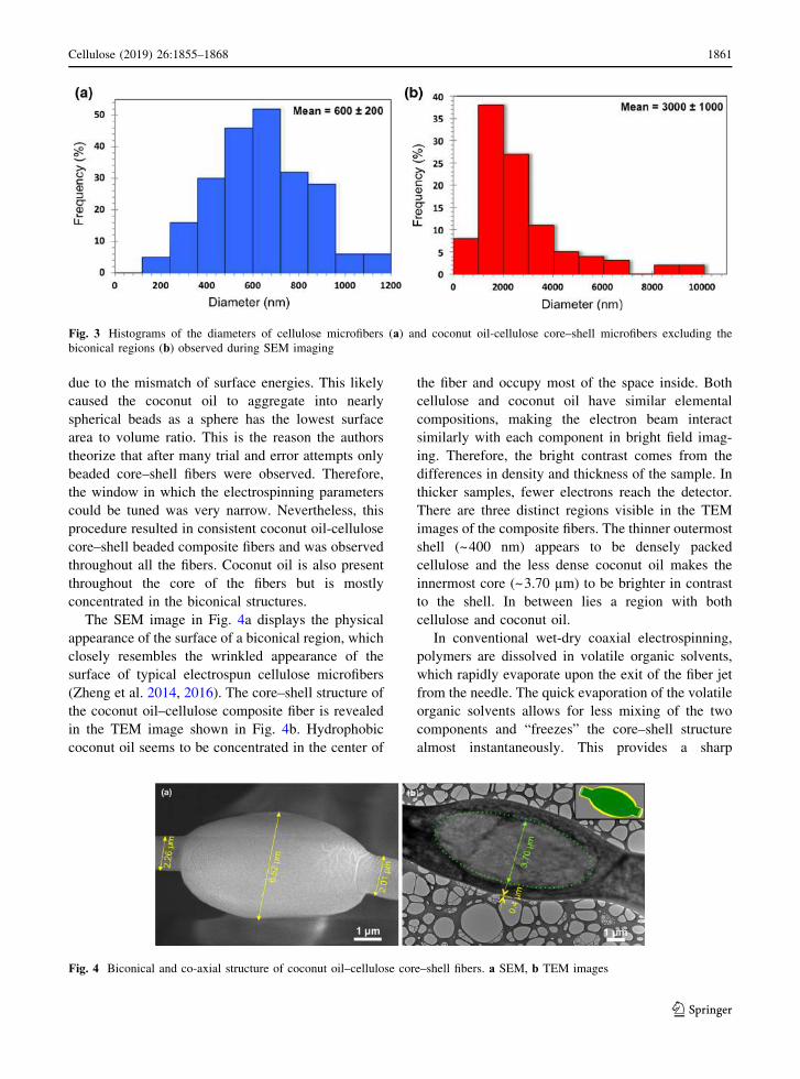
The cellulose monofilament fibers (negative con-
trol) appeared to have a continuous cylindrical
structure (Fig. 2a and SD, Fig. 1) with an average
diameter of 600±200 nm (Fig. 3a), which is
consistent with prior art (Kim et al. 2006). However,
the coconut oil–cellulose composite fiber morphology
was quite dissimilar from typical cellulose fibers. The
composite fibers appeared to have a beaded structure
with alternating cylindrical and biconical shaped
regions (Fig. 2b and SD, Fig. 2). The average
diameter of the fibers excluding the biconical regions
was 3000±1000 nm (Fig. 3b). The fabrication
process for the composite was developed through a
trial and error approach using a range of different
electrospinning parameters. In each instance that
core–shell behavior was observed, the composite
exhibited a beaded structure. All other instances
resulted in hollow fibers without coconut oil confined
inside the fibers or neat cellulose fibers. The beaded
nature of the composite is likely due to the differ-
ences in material properties between cellulose
and coconut oil. Cellulose, having many polar
functional groups, has a much higher surface energy
(67 mJ m2) (Miller and Donald 2002) than the
hydrophobic coconut oil (24 mJ m2) (Thangaraja
et al. 2016). In order for the free energy of the
composite to be minimized, the contact area between
the cellulose and coconut oil needs to be minimized
Fig. 2 Morphology of the electrospun microfibers. a SEM image of electrospun cellulose, Magnification-40,000, b SEM image of
electrospun coconut oil-cellulose core–shell fibers, Magnification-4000
1860 Cellulose (2019) 26:1855–1868
123
due to the mismatch of surface energies. This likely
caused the coconut oil to aggregate into nearly
spherical beads as a sphere has the lowest surface
area to volume ratio. This is the reason the authors
theorize that after many trial and error attempts only
beaded core–shell fibers were observed. Therefore,
the window in which the electrospinning parameters
could be tuned was very narrow. Nevertheless, this
procedure resulted in consistent coconut oil-cellulose
core–shell beaded composite fibers and was observed
throughout all the fibers. Coconut oil is also present
throughout the core of the fibers but is mostly
concentrated in the biconical structures.
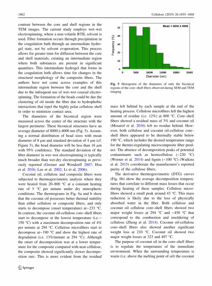
The SEM image in Fig. 4a displays the physical
appearance of the surface of a biconical region, which
closely resembles the wrinkled appearance of the
surface of typical electrospun cellulose microfibers
(Zheng et al. 2014, 2016). The core–shell structure of
the coconut oil–cellulose composite fiber is revealed
in the TEM image shown in Fig. 4b. Hydrophobic
coconut oil seems to be concentrated in the center of
the fiber and occupy most of the space inside. Both
cellulose and coconut oil have similar elemental
compositions, making the electron beam interact
similarly with each component in bright field imag-
ing. Therefore, the bright contrast comes from the
differences in density and thickness of the sample. In
thicker samples, fewer electrons reach the detector.
There are three distinct regions visible in the TEM
images of the composite fibers. The thinner outermost
shell (~400 nm) appears to be densely packed
cellulose and the less dense coconut oil makes the
innermost core (~3.70 µm) to be brighter in contrast
to the shell. In between lies a region with both
cellulose and coconut oil.
In conventional wet-dry coaxial electrospinning,
polymers are dissolved in volatile organic solvents,
which rapidly evaporate upon the exit of the fiber jet
from the needle. The quick evaporation of the volatile
organic solvents allows for less mixing of the two
components and “freezes” the core–shell structure
almost instantaneously. This provides a sharp
Fig. 3 Histograms of the diameters of cellulose microfibers (a) and coconut oil-cellulose core–shell microfibers excluding the
biconical regions (b) observed during SEM imaging
Fig. 4 Biconical and co-axial structure of coconut oil–cellulose core–shell fibers. a SEM, b TEM images
Cellulose (2019) 26:1855–1868 1861
123
contrast between the core and shell regions in the
TEM images. The current study employs wet–wet
electrospinning, where a non-volatile RTIL solvent is
used. Fiber formation occurs through precipitation in
the coagulation bath through an intermediate hydro-
gel state, not by solvent evaporation. This process
allows for greater time for diffusion between the core
and shell materials, creating an intermediate region
where both substances are present in significant
quantities. This intermediate hydrogel that forms in
the coagulation bath allows time for changes in the
structural morphology of the composite fibers. The
authors have not come across examples of this
intermediate region between the core and the shell
due to the infrequent use of wet–wet coaxial electro-
spinning. The formation of the beads could be due the
clustering of oil inside the fiber due to hydrophobic
interactions that repel the highly polar cellulose shell
in order to minimize contact area.
The diameters of the biconical region were
measured across the center of the structure with the
largest perimeter. These biconical structures have an
average diameter of 8000±4000 nm (Fig. 5). Assum-
ing a normal distribution of bead sizes with mean
diameter of 8 µm and standard deviation of 4 µm (cf.
Figure 5), the bead diameter will be less than 16 µmwith 95% confidence. The standard deviation of the
fiber diameter in wet–wet electrospinning is typically
much broader than wet-dry electrospinning as previ-
ously reported (Greiner and Wendorff 2007; Hou
et al. 2016; Lee et al. 2002; Li et al. 2006).
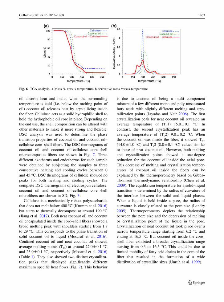
Coconut oil, cellulose and composite fibers were
subjected to thermogravimetric analysis where they
were heated from 20–800 °C at a constant heating
rate of 5 °C per minute under dry atmospheric
conditions. The thermograms in Fig. 6a and b show
that the coconut oil possesses better thermal stability
than either cellulose or composite fibers, and only
starts to decompose (onset temperature) at~233 °C.In contrast, the coconut oil-cellulose core–shell fibers
start to decompose at the lowest temperature (i.e.~
150 °C) with a maximum decomposition rate of 4%
per minute at 294 °C. Cellulose microfibers start to
decompose at~190 °C and show the highest rate of
degradation (i.e. 13%/minute at 294 °C). Althoughthe onset of decomposition was at a lower temper-
ature for the composite compared with neat cellulose,
the composite showed significantly slower decompo-
sition rate. This is more evident from the residual
mass left behind by each sample at the end of the
heating process. Cellulose microfibers left the highest
amount of residue (i.e. 12%) at 800 °C. Core–shellfibers showed a residual mass of 3% and coconut oil
(Mosarof et al. 2016) left no residue behind. How-
ever, both cellulose and coconut oil-cellulose core–
shell fibers appeared to be thermally stable below
190 °C, which includes the desired temperature range
for the thermo-regulating microcomposite fiber prod-
uct. The absence of decomposition peaks of potential
contaminants such as hemicellulose (~220 °C)(Werner et al. 2014) and lignin (~100 °C) (Watkins
et al. 2015) corroborate the manufacturer’s reported
purity of the cellulose fibers.
The derivative thermogravimetric (DTG) curves
(Fig. 6b) show the average decomposition tempera-
tures that correlate to different mass losses that occur
during heating of these samples. Cellulose micro-
fibers showed a small peak around 43 °C. This mass
reduction is likely due to the loss of physically
absorbed water in the fiber. Both cellulose and
coconut oil cellulose core–shell fibers showed two
major weight losses at 294 °C and ~450 °C that
correspond to the combustion and smoldering of
cellulose (Zheng et al. 2014). Coconut oil-cellulose
core–shell fibers also showed another significant
weight loss at 210 °C. Coconut oil showed two
major weight losses at 323 and 497 °C.The purpose of coconut oil in the core–shell fibers
is to regulate the temperature of the immediate
environment. When the surrounding temperature is
warm (i.e. above the melting point of oil) the coconut
Fig. 5 Histograms of the diameters of only the biconical
regions of the core–shell fibers observed during SEM and TEM
imaging
1862 Cellulose (2019) 26:1855–1868
123
oil absorbs heat and melts, when the surrounding
temperature is cold (i.e. below the melting point of
oil) coconut oil releases heat by crystallizing inside
the fiber. Cellulose acts as a solid hydrophilic shell to
hold the hydrophobic oil core in place. Depending on
the end use, the shell composition can be altered with
other materials to make it more strong and flexible.
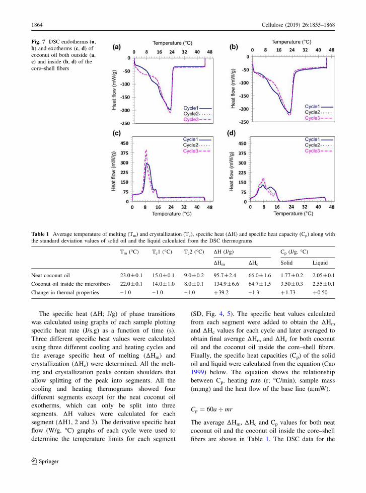
DSC analysis was used to determine the phase
transition properties of coconut oil and coconut oil–
cellulose core–shell fibers. The DSC thermograms of
coconut oil and coconut oil-cellulose core–shell
microcomposite fibers are shown in Fig. 7. Three
different exotherms and endotherms for each sample
were obtained by subjecting the samples to three
consecutive heating and cooling cycles between 0
and 45 °C. DSC thermograms of cellulose showed no
peaks for both heating and cooling cycles. The
complete DSC thermograms of electrospun cellulose,
coconut oil and coconut oil-cellulose core–shell
microfibers are shown in SD, Fig. 3.
Cellulose is a mechanically robust polysaccharide
that does not melt below 400 °C (Krumm et al. 2016)
but starts to thermally decompose at around 190 °C(Jiang et al. 2017). Both neat coconut oil and coconut
oil encapsulated inside the core–shell fibers showed a
broad melting peak with shoulders starting from 1.8
to 29 °C. This corresponds to the phase transition of
solid coconut oil to liquid (Mosarof et al. 2016).
Confined coconut oil and neat coconut oil showed
average melting points (Tm) at around 22.0±0.1 °Cand 23.0±0.1 °C, respectively (Mosarof et al. 2016)
(Table 1). They also showed two distinct crystalliza-
tion peaks that displayed significantly different
maximum specific heat flows (Fig. 7). This behavior
is due to coconut oil being a multi component
mixture of a few different mono and poly-unsaturated
fatty acids with slightly different melting and crys-
tallization points (Jayadas and Nair 2006). The first
crystallization peak for neat coconut oil revealed an
average temperature of (Tc1) 15.0±0.1 °C. In
contrast, the second crystallization peak has an
average temperature of (Tc2) 9.0±0.2 °C. When
the coconut oil was inside the fiber, it showed Tc1
(14.0±1.0 °C) and Tc2 (8.0±0.1 °C) values similar
to those of neat coconut oil. However, both melting
and crystallization points showed a one-degree
reduction for the coconut oil inside the axial pore.
This decrease of melting and crystallization temper-
atures of coconut oil inside the fibers can be
explained by the thermoporometry based on Gibbs–
Thomson thermodynamic relationship (Chen et al.
2009). The equilibrium temperature for a solid–liquid
transition is determined by the radius of curvature of
the interface between the solid and liquid phases.
When a liquid is held inside a pore, the radius of
curvature is closely related to the pore size (Landry
2005). Thermoporometry depicts the relationship
between the pore size and the depression of melting
or crystallization point of the liquid in the pore.
Crystallization of neat coconut oil took place over a
narrow temperature range starting from 6.2 °C and
ending at 16.5 °C. But coconut oil inside the core–
shell fiber exhibited a broader crystallization range
starting from 0.3 to 16.5 °C. This could be due to
limited mobility of fatty acid chains in the core of the
fiber that resulted in the formation of a wide
distribution of crystallite sizes (Unruh et al. 1999).
Fig. 6 TGA analysis. a Mass % versus temperature b derivative mass versus temperature
Cellulose (2019) 26:1855–1868 1863
123
The specific heat (ΔH; J/g) of phase transitions
was calculated using graphs of each sample plotting
specific heat rate (J/s.g) as a function of time (s).
Three different specific heat values were calculated
using three different cooling and heating cycles and
the average specific heat of melting (ΔHm) and
crystallization (ΔHc) were determined. All the melt-
ing and crystallization peaks contain shoulders that
allow splitting of the peak into segments. All the
cooling and heating thermograms showed four
different segments except for the neat coconut oil
exotherms, which can only be split into three
segments. ΔH values were calculated for each
segment (ΔH1, 2 and 3). The derivative specific heat
flow (W/g. °C) graphs of each cycle were used to
determine the temperature limits for each segment
(SD, Fig. 4, 5). The specific heat values calculated
from each segment were added to obtain the ΔHm
and ΔHc values for each cycle and later averaged to
obtain final average ΔHm and ΔHc for both coconut
oil and the coconut oil inside the core–shell fibers.
Finally, the specific heat capacities (Cp) of the solid
oil and liquid were calculated from the equation (Cao
1999) below. The equation shows the relationship
between Cp, heating rate (r; °C/min), sample mass
(m;mg) and the heat flow of the base line (a;mW).
Cp ¼ 60a� mr
The average ΔHm, ΔHc and Cp values for both neat
coconut oil and the coconut oil inside the core–shell
fibers are shown in Table 1. The DSC data for the
Fig. 7 DSC endotherms (a,b) and exotherms (c, d) ofcoconut oil both outside (a,c) and inside (b, d) of thecore–shell fibers
Table 1 Average temperature of melting (Tm) and crystallization (Tc), specific heat (ΔH) and specific heat capacity (Cp) along with
the standard deviation values of solid oil and the liquid calculated from the DSC thermograms
Tm (°C) Tc1 (°C) Tc2 (°C) ΔH (J/g) Cp (J/g. °C)
ΔHm ΔHc Solid Liquid
Neat coconut oil 23.0±0.1 15.0±0.1 9.0±0.2 95.7±2.4 66.0±1.6 1.77±0.2 2.05±0.1
Coconut oil inside the microfibers 22.0±0.1 14.0±1.0 8.0±0.1 134.9±6.6 64.7±1.5 3.50±0.3 2.55±0.1
Change in thermal properties −1.0 −1.0 −1.0 +39.2 −1.3 +1.73 +0.50
1864 Cellulose (2019) 26:1855–1868
123
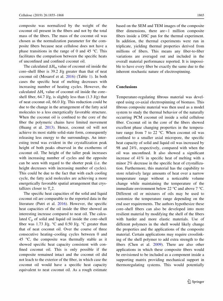
composite was normalized by the weight of the
coconut oil present in the fibers and not by the total
mass of the fibers. The mass of the coconut oil was
chosen as the normalization parameter for the com-
posite fibers because neat cellulose does not have a
phase transitions in the range of 0 and 45 °C. Thisfacilitates the comparison between the specific heats
of unconfined and confined coconut oil.
The calculated ΔHm value of coconut oil inside the
core–shell fiber is 39.2 J/g greater than that of neat
coconut oil (Mosarof et al. 2016) (Table 1). In both
cases the specific heat of melting decreases with
increasing number of heating cycles. However, the
calculated ΔHc value of coconut oil inside the core–
shell fiber, 64.7 J/g, is slightly less than (1.3 J/g) that
of neat coconut oil, 66.0 J/g. This reduction could be
due to the change in the arrangement of the fatty acid
molecules to a less energetically favorable structure.
When the coconut oil is confined to the core of the
fiber the polymeric chains have limited movement
(Huang et al. 2013). Hence, coconut oil will not
achieve its most stable solid-state form, consequently
releasing less energy to the surroundings. An inter-
esting trend was evident in the crystallization peak
height of both peaks observed in the exotherms of
coconut oil. The height of the taller peak increases
with increasing number of cycles and the opposite
can be seen with regard to the shorter peak (i.e. the
height decreases with increasing number of cycles).
This could be due to the fact that with each cooling
cycle, the fatty acid molecules are achieving a more
energetically favorable spatial arrangement that crys-
tallizes closer to Tc2.
The specific heat capacities of the solid and liquid
coconut oil are comparable to the reported data in the
literature (Putri et al. 2016). However, the specific
heat capacities of the oil inside the fiber showed an
interesting increase compared to neat oil. The calcu-
lated Cp of solid and liquid oil inside the core–shell
fiber was 1.73 J/g. °C and 0.50 J/g. °C greater than
that of neat coconut oil. Over the course of three
consecutive heating–cooling cycles between 0 and
45 °C, the composite was thermally stable as it
showed specific heat capacity consistent with con-
fined coconut oil. This is only possible if the
composite remained intact and the coconut oil did
not leach to the exterior of the fiber, in which case the
coconut oil would have a specific heat capacity
equivalent to neat coconut oil. As a rough estimate
based on the SEM and TEM images of the composite
fiber dimensions, there are~1 million composite
fibers inside a DSC pan for the thermal experiment.
In addition, the thermal experiments were run in
triplicate, yielding thermal properties derived from
millions of fibers. This means any fiber-to-fiber
variations are averaged out and included in the
overall material performance reported. It is impossi-
ble to have every fiber be exactly the same due to the
inherent stochastic nature of electrospinning.
Conclusions
Temperature-regulating fibrous material was devel-
oped using co-axial electrospinning of biomass. This
fibrous composite material was then used as a model
system to study the thermal behavior of the naturally
occurring PCM coconut oil inside a solid cellulose
fiber. Coconut oil in the core of the fibers showed
excellent phase changing properties in the tempera-
ture range from 7 to 22 °C. When coconut oil was
confined to a smaller axial micropore, the specific
heat capacity of solid and liquid oil was increased by
98 and 24%, respectively, compared with when the
oil was unconfined. It also showed a significant
increase of 41% in specific heat of melting with a
minor 2% decrease in the specific heat of crystalliza-
tion. Furthermore, this material has the capability to
store relatively large amounts of heat over a narrow
temperature range without a noticeable volume
change while maintaining the temperature of the
immediate environment below 22 °C and above 7 °C.Different oil or mixtures of oils may be used to
customize the temperature range depending on the
end user requirements. The authors hypothesize these
core–shell fibers can also be developed into more
resilient material by modifying the shell of the fibers
with harder and more elastic materials. Use of
different polymers in the shell would likely change
the properties and the applications of the composite
material. Certain applications may require crosslink-
ing of the shell polymer to add extra strength to the
fibers (Chen et al. 2009). There are also other
applications in which these composite fibers would
be envisioned to be included as a component inside a
supporting matrix providing mechanical support in
thermoregulating systems. This would potentially
Cellulose (2019) 26:1855–1868 1865
123
enable a broader range of applications in the textile
industry for novel thermal insulation materials.
Acknowledgments The authors duly acknowledge the
following people for their assistance in handling
characterization instruments. Manager of electron microscopy
laboratory Mr. Raymond P Dove for TEM assistance and Mr.
David Frey, senior application engineer, center for integrated
electronics for SEM assistance. Analytical core facility director
Dr. Joel Morgan for TGA and DSC assistance. Mr. Josh
Bostick, Mechanical Engineering Senior, RPI for assistance in
designing the anti-static polycarbonate box. Finally, I would
like to thank my fellow researchers and colleagues for their
support rendered during this project.
Author’s Contributions The study was performed by W.M.R.
N.U., C.F.W., C.M. and C.C. and the manuscript was written
by W.M.R.N.U. & R.J.L. All authors have given their approval
to the final version of this manuscript.
Compliance with ethical standards
Conflict of interest All authors declares that they do not have
conflict of interest.
References
Abhat A (1983) Low temperature latent heat thermal energy
storage: heat storage materials. Sol Energy 30:313–332
Ajithkumar G, Jayadas N, Bhasi M (2009) Analysis of the pour
point of coconut oil as a lubricant base stock using dif-
ferential scanning calorimetry. Lubr Sci 21:13–26
Arioli T, Peng L, Betzner AS, Burn J, Wittke W, Herth W,
Camilleri C, Hofte H, Plazinski J, Birch R (1998)
Molecular analysis of cellulose biosynthesis in arabidop-
sis. Science 279:717–720
Boardman B (2013) Fixing fuel poverty: challenges and solu-
tions. Routledge, London
Cadarette BS, Cheuvront SN, Kolka MA, Stephenson LA,
Montain SJ, Sawka MN (2006) Intermittent microclimate
cooling during exercise-heat stress in us army chemical
protective clothing. Ergonomics 49:209–219
Cao J (1999) Mathematical studies of modulated differential
scanning calorimetry: I. Heat capacity measurements.
Thermochim Acta 325:101–109
Chen C, Wang L, Huang Y (2007) Electrospinning of thermo-
regulating ultrafine fibers based on polyethylene gly-
col/cellulose acetate composite. Polymer 48:5202–5207
Chen C, Wang L, Huang Y (2009) Crosslinking of the elec-
trospun polyethylene glycol/cellulose acetate composite
fibers as shape-stabilized phase change materials. Mater
Lett 63:569–571
Chen Z, Wang P, Wei B, Mo X, Cui F (2010) Electrospun
collagen–chitosan nanofiber: A biomimetic extracellular
matrix for endothelial cell and smooth muscle cell. Acta
Biomater 6:372–382
Chen C, Wang L, Huang Y (2011) Electrospun phase change
fibers based on polyethylene glycol/cellulose acetate
blends. Appl Energy 88:3133–3139
Cooley JF (1902) Apparatus for electrically dispersing fluids.
U.S. Patent US692631A, 1902
Coyle S, Wu Y, Lau K-T, De Rossi D, Wallace G, Diamond D
(2007) Smart nanotextiles: a review of materials and
applications. MRS Bull 32:434–442
Fang X, Zhang Z (2006) A novel montmorillonite-based
composite phase change material and its applications in
thermal storage building materials. Energy Build 38:377–
380
Fang Y, Kuang S, Gao X, Zhang Z (2008) Preparation and
characterization of novel nanoencapsulated phase change
materials. Energy Convers Manage 49:3704–3707
Fang G, Chen Z, Li H (2010) Synthesis and properties of
microencapsulated paraffin composites with sio 2 shell as
thermal energy storage materials. Chem Eng J 163:154–
159
Farid MM, Khudhair AM, Razack SAK, Al-Hallaj S (2004) A
review on phase change energy storage: materials and
applications. Energy Convers Manage 45:1597–1615
Farran A, Cai C, Sandoval M, Xu Y, Liu J, Hernaiz MJ, Lin-
hardt RJ (2015) Green solvents in carbohydrate chemistry:
from raw materials to fine chemicals. Chem Rev
115:6811–6853
Flouris AD, Cheung SS (2006) Design and control optimiza-
tion of microclimate liquid cooling systems underneath
protective clothing. Ann Biomed Eng 34:359
Freire MG, Teles ARR, Ferreira RA, Carlos LD, Lopes-da-
Silva JA, Coutinho JA (2011) Electrospun nanosized
cellulose fibers using ionic liquids at room temperature.
Green Chem 13:3173–3180
Frenot A, Henriksson MW, Walkenstrom P (2007) Electro-
spinning of cellulose-based nanofibers. J Appl Polym Sci
103:1473–1482
Greiner A, Wendorff JH (2007) Electrospinning: A fascinating
method for the preparation of ultrathin fibers. Angew
Chem Int Edit 46:5670–5703
Hasnain S (1998) Review on sustainable thermal energy stor-
age technologies, part I: heat storage materials and
techniques. Energy Convers Manage 39:1127–1138
Hou L, Udangawa WRN, Pochiraju A, Dong W, Zheng Y,
Linhardt RJ, Simmons TJ (2016) Synthesis of heparin-
immobilized, magnetically addressable cellulose nanofi-
bers for biomedical applications. ACS Biomater Sci Eng
2:1905–1913
Huang H-D, Xu J-Z, Fan Y, Xu L, Li Z-M (2013) Poly (l-lactic
acid) crystallization in a confined space containing gra-
phene oxide nanosheets. J Phys Chem B 117:10641–
10651
Huang F, Xu Y, Peng B, Su Y, Jiang F, Hsieh Y-L, Wei Q
(2015) Coaxial electrospun cellulose-core fluoropolymer-
shell fibrous membrane from recycled cigarette filter as
separator for high performance lithium-ion battery. ACS
Sustain Chem Eng 3:932–940
Iqbal K, Sun D (2014) Development of thermo-regulating
polypropylene fibre containing microencapsulated phase
change materials. Renew Energy 71:473–479
Jaganathan SK, Fauzi Ismail A (2017) Production and hemo-
compatibility assessment of novel electrospun
1866 Cellulose (2019) 26:1855–1868
123
polyurethane nanofibers loaded with dietary virgin coco-
nut oil for vascular graft applications. J Bioact Compat
Polym 33:210–223
Jayadas N, Nair KP (2006) Coconut oil as base oil for indus-
trial lubricants—evaluation and modification of thermal,
oxidative and low temperature properties. Tribol Int
39:873–878
Jiang Z, Chen D, Yu Y, Miao J, Liu Y, Zhang L (2017)
Composite fibers prepared from multi-walled carbon
nanotubes/cellulose dispersed/dissolved in ammonium/
dimethyl sulfoxide mixed solvent. RSC Adv 7:2186–2192
Khalil HA, Bhat A, Yusra AI (2012) Green composites from
sustainable cellulose nanofibrils: a review. Carbohyd
Polym 87:963–979
Kim C-W, Kim D-S, Kang S-Y, Marquez M, Joo YL (2006)
Structural studies of electrospun cellulose nanofibers.
Polymer 47:5097–5107
Krumm C, Pfaendtner J, Dauenhauer PJ (2016) Millisecond
pulsed films unify the mechanisms of cellulose fragmen-
tation. Chem Mater 28:3108–3114
Lalia BS, Guillen-Burrieza E, Arafat HA, Hashaikeh R (2013)
Fabrication and characterization of polyvinylidenefluo-
ride-co-hexafluoropropylene (pvdf-hfp) electrospun
membranes for direct contact membrane distillation.
J Membrane Sci 428:104–115
Lan T, Shao Z-Q, Wang J-Q, Gu M-J (2015) Fabrication of
hydroxyapatite nanoparticles decorated cellulose triac-
etate nanofibers for protein adsorption by coaxial
electrospinning. Chem Eng J 260:818–825
Landry MR (2005) Thermoporometry by differential scanning
calorimetry: experimental considerations and applica-
tions. Thermochim Acta 433:27–50
Lee KH, Kim HY, La YM, Lee DR, Sung NH (2002) Influence
of a mixing solvent with tetrahydrofuran and n,
n-dimethylformamide on electrospun poly (vinyl chloride)
nonwoven mats. J Polym Sci Pol Phys 40:2259–2268
Li Y, Huang Z, Lu Y (2006) Electrospinning of nylon-6, 66,
1010 terpolymer. Eur Polym J 42:1696–1704
Li F, Zhao Y, Song Y (2010) Core-shell nanofibers: nano
channel and capsule by coaxial electrospinning. In:
Kumar A (ed) nanofibers. InTech, Croatia, pp 419–438
Liebert T (2010) Cellulose solvents-remarkable history, bright
future. In: Liebert TF, Heinze TJ, Edgar KJ (eds) Cellu-
lose solvents: for analysis, shaping and chemical
modification, vol 1033. Acs symposium series. Oxford
University Press, Oxford, pp 3–54
Liu H, Hsieh YL (2002) Ultrafine fibrous cellulose membranes
from electrospinning of cellulose acetate. J Polym Sci Pol
Phys 40:2119–2129
Mahadeva SK, Kim J (2012) Influence of residual ionic liquid
on the thermal stability and electromechanical behavior of
cellulose regenerated from 1-ethyl-3-methylimidazolium
acetate. Fiber Polym 13:289–294
McCann JT, Marquez M, Xia Y (2006) Melt coaxial electro-
spinning: a versatile method for the encapsulation of solid
materials and fabrication of phase change nanofibers.
Nano Lett 6:2868–2872
Meli L, Miao J, Dordick JS, Linhardt RJ (2010) Electrospin-
ning from room temperature ionic liquids for biopolymer
fiber formation. Green Chem 12:1883–1892
Meng Q, Li G, Hu J (2015) Phase change fibers and assem-
blies. In: Tao X (ed) Handbook of smart textiles. Springer,
Singapore, pp 225–251
Miao J, Pangule RC, Paskaleva EE, Hwang EE, Kane RS,
Linhardt RJ, Dordick JS (2011) Lysostaphin-functional-
ized cellulose fibers with antistaphylococcal activity for
wound healing applications. Biomaterials 32:9557–9567
Miller AF, Donald AM (2002) Surface and interfacial tension
of cellulose suspensions. Langmuir 18:10155–10162
Miyauchi M, Miao J, Simmons TJ, Lee J-W, Doherty TV,
Dordick JS, Linhardt RJ (2010) Conductive cable fibers
with insulating surface prepared by coaxial electrospin-
ning of multiwalled nanotubes and cellulose.
Biomacromol 11:2440–2445
Miyauchi M, Miao J, Simmons T, Dordick J, Linhardt R (2011)
Flexible electrospun cellulose fibers as an affinity packing
material for the separation of bovine serum albumin.
J Chromatogr Sep Tech 2:110
Mondal S (2008) Phase change materials for smart textiles–an
overview. Appl Therm Eng 28:1536–1550
Mosarof M, Kalam M, Masjuki H, Arslan A, Monirul I, Ruhul
A, Shahir S, Khuong L (2016) Analysis of thermal sta-
bility and lubrication characteristics of millettia pinnata
oil. RSC Adv 6:81414–81425
Nejman A, Goetzendorf-Grabowska B (2013) Heat balance of
textile materials modified with the mixtures of pcm
microcapsules. Thermochim Acta 569:144–150
Nelson G (2002) Application of microencapsulation in textiles.
Int J Pharm 242:55–62
Putri WA, Fahmi Z, Sutjahja I, Kurnia D, Wonorahardjo S
(2016) Thermophysical parameters of coconut oil and its
potential application as the thermal energy storage system
in indonesia. J Phys: Conf Ser 739:012065
Quan S-L, Kang S-G, Chin I-J (2010) Characterization of
cellulose fibers electrospun using ionic liquid. Cellulose
17:223–230
Si Y, Yu J, Tang X, Ge J, Ding B (2014) Ultralight nanofibre-
assembled cellular aerogels with superelasticity and
multifunctionality. Nat Commun 5:5802
Simmons TJ, Lee SH, Miao J, Miyauchi M, Park T-J, Bale SS,
Pangule R, Bult J, Martin JG, Dordick JS (2011) Prepa-
ration of synthetic wood composites using ionic liquids.
Wood Sci Technol 45:719–733
Swatloski RP, Spear SK, Holbrey JD, Rogers RD (2002)
Dissolution of cellose with ionic liquids. J Am Chem Soc
124:4974–4975
Teo WE, Ramakrishna S (2006) A review on electrospinning
design and nanofibre assemblies. Nanotechnology 17:R89
Thangaraja J, Anand K, Mehta PS (2016) Predicting surface
tension for vegetable oil and biodiesel fuels. RSC Adv
6:84645–84657
Unruh T, Bunjes H, Westesen K, Koch MH (1999) Observation
of size-dependent melting in lipid nanoparticles. J Phys
Chem B 103:10373–10377
Vatankhah E, Semnani D, Prabhakaran MP, Tadayon M,
Razavi S, Ramakrishna S (2014) Artificial neural network
for modeling the elastic modulus of electrospun poly-
caprolactone/gelatin scaffolds. Acta Biomater 10:709–721
Vigo TL, Frost C (1982) Temperature-sensitive hollow fibers
containing phase change salts. Text Res J 52:633–637
Cellulose (2019) 26:1855–1868 1867
123
Vigo TL, Frost CM (1983) Temperature adaptable hollow
fibers containing polyethylene glycols. J Coat Fabr
12:243–254
Viswanathan G, Murugesan S, Pushparaj V, Nalamasu O,
Ajayan PM, Linhardt RJ (2006) Preparation of biopoly-
mer fibers by electrospinning from room temperature
ionic liquids. Biomacromol 7:415–418
Walker JW (2009) Ask the experts: When air is the same
temperature as our body, why do we feel hot? Sci Am
300:84
Watkins D, Nuruddin M, Hosur M, Tcherbi-Narteh A, Jeelani
S (2015) Extraction and characterization of lignin from
different biomass resources. J Mater Res Technol 4:26–32
Werner K, Pommer L, Brostrom M (2014) Thermal decom-
position of hemicelluloses. J Anal Appl Pyrol 110:130–
137
Yu D, Wang X, Li X, Chian W, Li Y, Liao Y (2013a) Elec-
trospun biphasic drug release polyvinylpyrrolidone/ethyl
cellulose core/sheath nanofibers. Acta Biomater 9:5665–
5672
Yu D-G, Chian W, Wang X, Li X-Y, Li Y, Liao Y-Z (2013b)
Linear drug release membrane prepared by a modified
coaxial electrospinning process. J Membrane Sci
428:150–156
Zhang Y, Zhou G, Lin K, Zhang Q, Di H (2007) Application of
latent heat thermal energy storage in buildings: state-of-
the-art and outlook. Build Environ 42:2197–2209
Zheng Y, Miao J, Maeda N, Frey D, Linhardt RJ, Simmons TJ
(2014) Uniform nanoparticle coating of cellulose fibers
during wet electrospinning. J Mater Chem A 2:15029–
15034
Zheng Y, Cai C, Zhang F, Monty J, Linhardt RJ, Simmons TJ
(2016) Can natural fibers be a silver bullet? Antibacterial
cellulose fibers through the covalent bonding of silver
nanoparticles to electrospun fibers. Nanotechnology
27:055102
1868 Cellulose (2019) 26:1855–1868
123