Embed Size (px)
Citation preview
Copyright 2013 Tyco Electronics. TE Connectivity, TE connectivity (logo) and TE (logo) are trademarks. Other logos, product and/or
company names might be trademarks of their respective owners.
1
COB Corner Holders- Application Considerations
Ron Weber
TE Industrial Business Unit, Intelligent Buildings
Harrisburg, PA
Abstract The lighting market is evolving rapidly from traditional lighting into Solid State Lighting (SSL) technology. The main drivers for this change are the need for greater energy efficiency due to rising energy costs and new legislation both of which have global implications. With the market drive to mass adoption of SSL technology, the development and introduction of lighting fixtures that incorporate COB (chip-on-board) LED arrays is fast with short life cycles. Manufacturers need to drive towards more efficient and reliable processes in their manufacturing plans to accommodate these quick cycles. It is well acknowledged that soldering wires to COBs is a time-consuming, variable process. Lighting fixture designers desire socket solutions for their COB LEDs for reliable thermal, electrical, and mechanical connections in their luminaries. The article outlines COB background, issues and challenges with COBs, and a unique socket approach that addresses these.
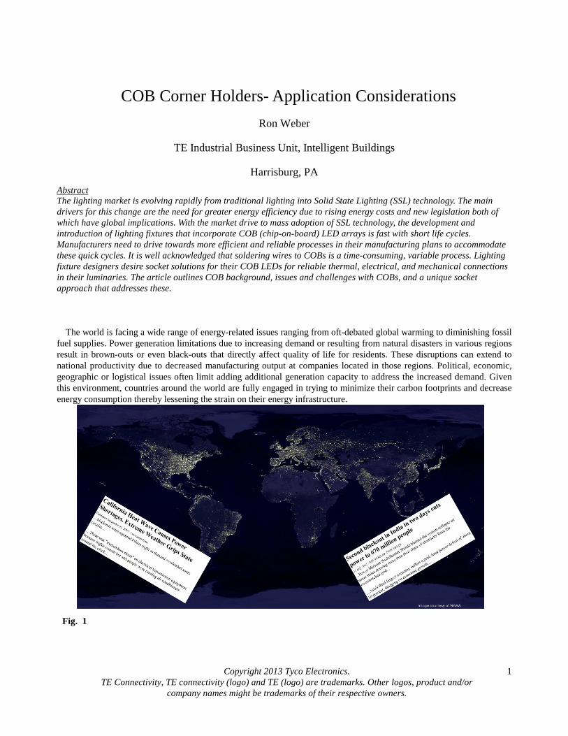
The world is facing a wide range of energy-related issues ranging from oft-debated global warming to diminishing fossil fuel supplies. Power generation limitations due to increasing demand or resulting from natural disasters in various regions result in brown-outs or even black-outs that directly affect quality of life for residents. These disruptions can extend to national productivity due to decreased manufacturing output at companies located in those regions. Political, economic, geographic or logistical issues often limit adding additional generation capacity to address the increased demand. Given this environment, countries around the world are fully engaged in trying to minimize their carbon footprints and decrease energy consumption thereby lessening the strain on their energy infrastructure.
Fig. 1
Copyright 2013 Tyco Electronics. TE Connectivity, TE connectivity (logo) and TE (logo) are trademarks. Other logos, product and/or
company names might be trademarks of their respective owners.
2
One major global effort is to decrease the energy load posed by the inefficient lighting systems in use today. Increasing
global population and the resulting increase in demand for lighting can no longer be served by incandescent sources that accounted for 79% of light source sales volume in 2006. Collectively today, lighting energy consumption accounts for around 18% of the total global generated energy and can not be allowed to continue1. Simply switching to readily available more energy efficient light sources such as CFLs or LEDs can result in a 40% energy savings that would eliminate 630 million tonnes of CO2 and 1800 million barrels of oil. It would further cut down on the power generating footprint eliminating the need for almost six hundred 2TW/yr power plants2. Although it is neither feasible nor realistic to expect this change to happen overnight, phased regulations are in place around the world to “ban the bulb”. These are progressing and driving the changeover to incandescent alternatives such as CFLs and LEDs.
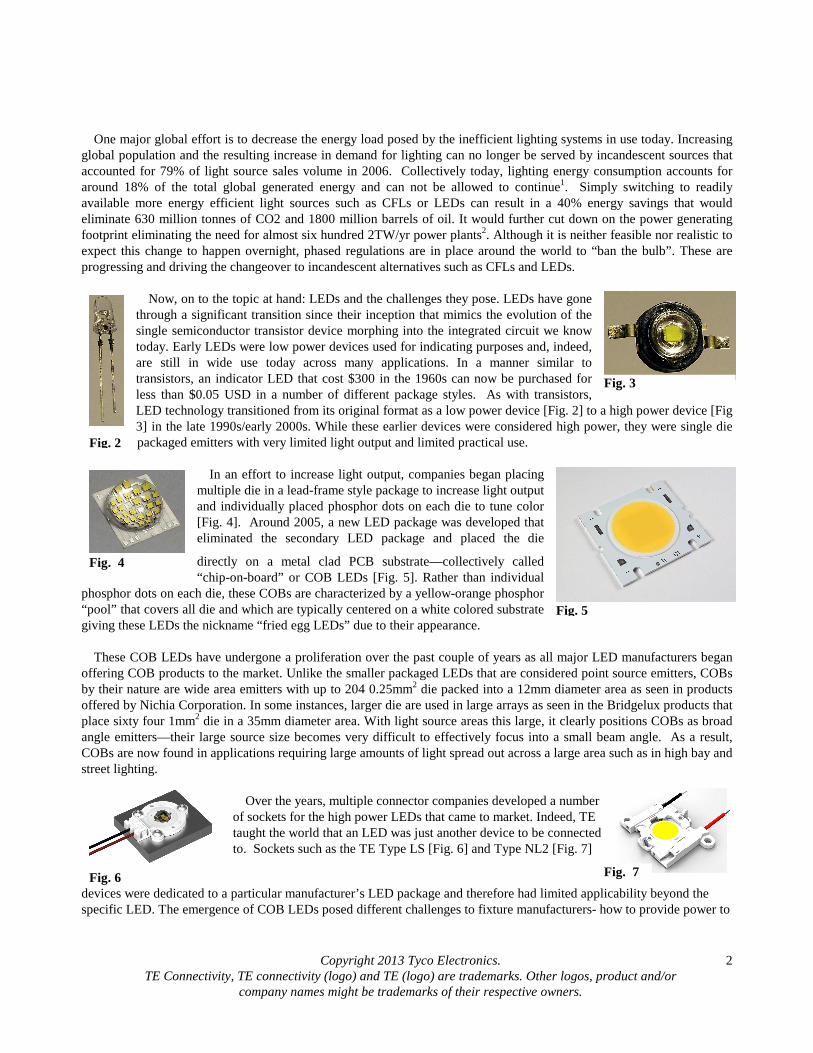
Now, on to the topic at hand: LEDs and the challenges they pose. LEDs have gone
through a significant transition since their inception that mimics the evolution of the single semiconductor transistor device morphing into the integrated circuit we know today. Early LEDs were low power devices used for indicating purposes and, indeed, are still in wide use today across many applications. In a manner similar to transistors, an indicator LED that cost $300 in the 1960s can now be purchased for less than $0.05 USD in a number of different package styles. As with transistors, LED technology transitioned from its original format as a low power device [Fig. 2] to a high power device [Fig 3] in the late 1990s/early 2000s. While these earlier devices were considered high power, they were single die packaged emitters with very limited light output and limited practical use.
In an effort to increase light output, companies began placing
multiple die in a lead-frame style package to increase light output and individually placed phosphor dots on each die to tune color [Fig. 4]. Around 2005, a new LED package was developed that eliminated the secondary LED package and placed the die
directly on a metal clad PCB substrate—collectively called “chip-on-board” or COB LEDs [Fig. 5]. Rather than individual
phosphor dots on each die, these COBs are characterized by a yellow-orange phosphor “pool” that covers all die and which are typically centered on a white colored substrate giving these LEDs the nickname “fried egg LEDs” due to their appearance.
These COB LEDs have undergone a proliferation over the past couple of years as all major LED manufacturers began
offering COB products to the market. Unlike the smaller packaged LEDs that are considered point source emitters, COBs by their nature are wide area emitters with up to 204 0.25mm2 die packed into a 12mm diameter area as seen in products offered by Nichia Corporation. In some instances, larger die are used in large arrays as seen in the Bridgelux products that place sixty four 1mm2 die in a 35mm diameter area. With light source areas this large, it clearly positions COBs as broad angle emitters—their large source size becomes very difficult to effectively focus into a small beam angle. As a result, COBs are now found in applications requiring large amounts of light spread out across a large area such as in high bay and street lighting.
Over the years, multiple connector companies developed a number
of sockets for the high power LEDs that came to market. Indeed, TE taught the world that an LED was just another device to be connected to. Sockets such as the TE Type LS [Fig. 6] and Type NL2 [Fig. 7]
devices were dedicated to a particular manufacturer’s LED package and therefore had limited applicability beyond the specific LED. The emergence of COB LEDs posed different challenges to fixture manufacturers- how to provide power to
Fig. 2
Fig. 3
Fig. 4
Fig. 5
Fig. 6 Fig. 7
Copyright 2013 Tyco Electronics. TE Connectivity, TE connectivity (logo) and TE (logo) are trademarks. Other logos, product and/or
company names might be trademarks of their respective owners.
3
these devices and then affix them to heatsinks in the lighting fixtures. The traditional method was to hand-solder the wires to the pads on the substrate [Fig. 8] and then secure these assemblies with screws to the heatsink- a process that was time consuming and subject to variability. As with the earlier discrete devices, this presented an ideal opportunity for socket solutions. TE and other connector companies addressed this emergence of initial COB devices the same way earlier discrete LED packages were addressed: custom sockets. As other COBs started to enter the market, connector manufacturers realized the status quo method of developing a socket for each would be prohibitively expensive and time consuming resulting in never-ending efforts forever chasing the next new COB to enter the market.
With well over 50 different COB products commercially available around the world from multiple manufacturers,
finding a single solution to address each would be a challenge to say the least. Aside from the fact that all were rectangular, all had two electrical contact pads and most had circular light emitting areas, there were few other dimensional similarities. This presents a challenge to connector companies…How do we address these varied but similar COB LEDs with a minimum of engineering and tooling expenditure while providing a future-proof & flexible platform based product?
One such solution is a flexible, scalable, platform-based socket solution. An analysis of available COBs yielded a crack
in the shell of these “fried egg” LEDs . While not exactly identical, there are similarities between contact pad locations that, when combined with the rectangular nature of the devices and diagonal contact pad placement form the basis for the platform solution. As a result, a holder product, referenced off the corners of the COB, could yield a virtually limitless array of use scenarios with the varied COBs available on the market as well as those to come in the future.
The substrate differences among LEDs is yet another issue that needs to be tackled by socket/holder suppliers. While
most of the early COBs incorporated aluminum substrates, further investigation of the commercially available COBs indicated a number of COBs that are based on ceramic substrates (typically aluminum nitride). While not a significant differentiator, these two substrate variants have physical features that differ enough to require special handling due to their different material properties. The aluminum substrate COBs are rather robust and in some instances are mounted using machine screws. On the other hand, ceramic-based COBs create some frustration for fixture manufacturers since unlike aluminum-based substrates where they could simply secure the COBs with a screw to a heatsink, these ceramic substrates were far too brittle to secure with screws and thereby mandated some sort of secondary attachment to ensure suitable thermal performance. This attachment needs to be accomplished using thermal adhesives or by a mechanical holder that provides thermal normal force, mechanical attachment, and electrical interconnection.
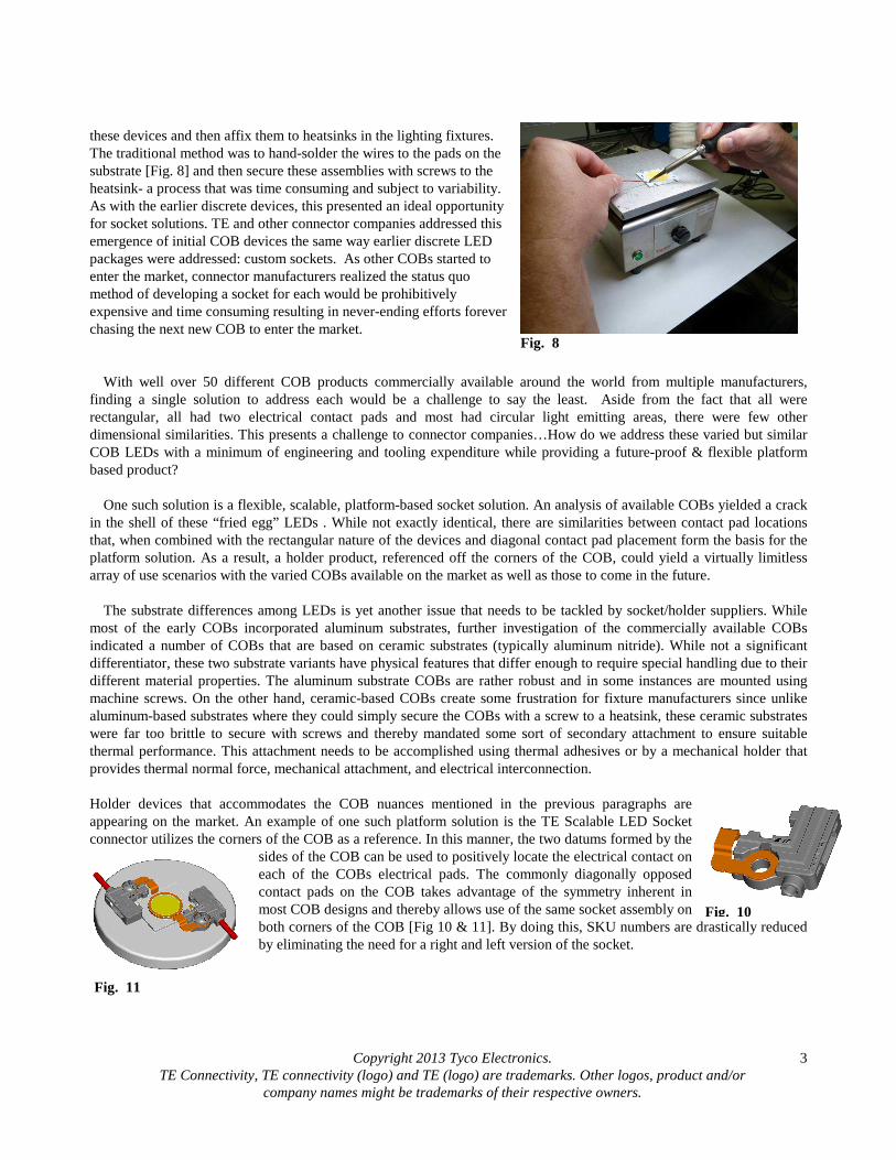
Holder devices that accommodates the COB nuances mentioned in the previous paragraphs are appearing on the market. An example of one such platform solution is the TE Scalable LED Socket connector utilizes the corners of the COB as a reference. In this manner, the two datums formed by the
sides of the COB can be used to positively locate the electrical contact on each of the COBs electrical pads. The commonly diagonally opposed contact pads on the COB takes advantage of the symmetry inherent in most COB designs and thereby allows use of the same socket assembly on both corners of the COB [Fig 10 & 11]. By doing this, SKU numbers are drastically reduced by eliminating the need for a right and left version of the socket.
Fig. 8
Fig. 10
Fig. 11
Copyright 2013 Tyco Electronics. TE Connectivity, TE connectivity (logo) and TE (logo) are trademarks. Other logos, product and/or
company names might be trademarks of their respective owners.
4
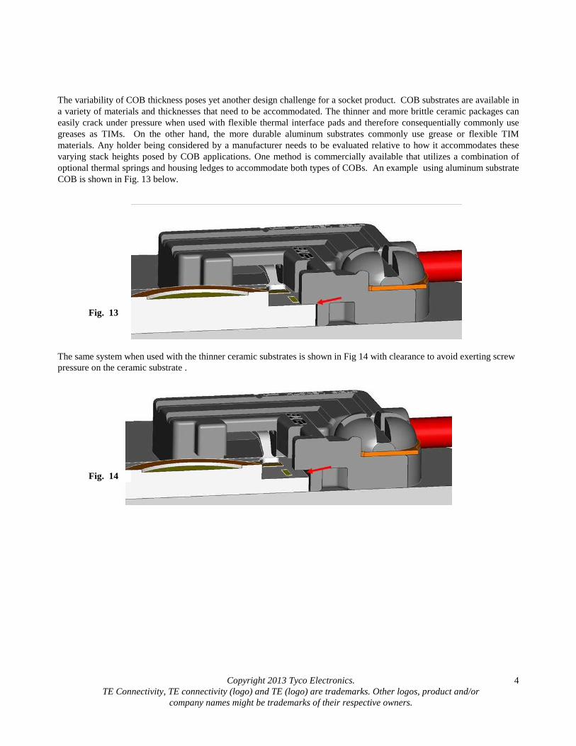
The variability of COB thickness poses yet another design challenge for a socket product. COB substrates are available in a variety of materials and thicknesses that need to be accommodated. The thinner and more brittle ceramic packages can easily crack under pressure when used with flexible thermal interface pads and therefore consequentially commonly use greases as TIMs. On the other hand, the more durable aluminum substrates commonly use grease or flexible TIM materials. Any holder being considered by a manufacturer needs to be evaluated relative to how it accommodates these varying stack heights posed by COB applications. One method is commercially available that utilizes a combination of optional thermal springs and housing ledges to accommodate both types of COBs. An example using aluminum substrate COB is shown in Fig. 13 below.
The same system when used with the thinner ceramic substrates is shown in Fig 14 with clearance to avoid exerting screw pressure on the ceramic substrate .
Fig. 13
Fig. 14
Copyright 2013 Tyco Electronics. TE Connectivity, TE connectivity (logo) and TE (logo) are trademarks. Other logos, product and/or
company names might be trademarks of their respective owners.
5
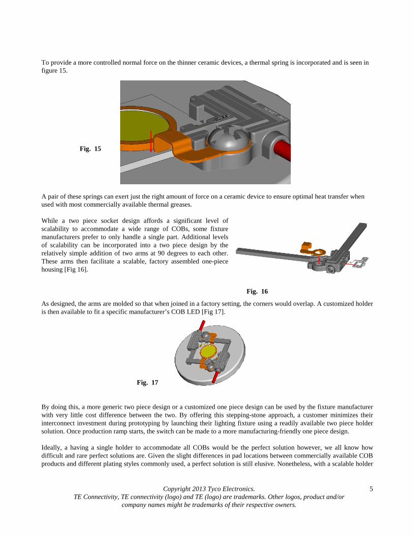
To provide a more controlled normal force on the thinner ceramic devices, a thermal spring is incorporated and is seen in figure 15.
A pair of these springs can exert just the right amount of force on a ceramic device to ensure optimal heat transfer when used with most commercially available thermal greases. While a two piece socket design affords a significant level of scalability to accommodate a wide range of COBs, some fixture manufacturers prefer to only handle a single part. Additional levels of scalability can be incorporated into a two piece design by the relatively simple addition of two arms at 90 degrees to each other. These arms then facilitate a scalable, factory assembled one-piece housing [Fig 16].
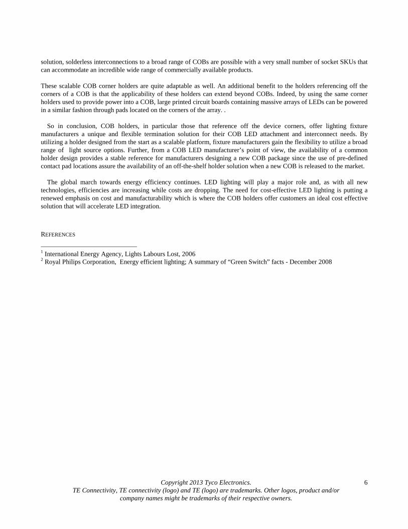
As designed, the arms are molded so that when joined in a factory setting, the corners would overlap. A customized holder is then available to fit a specific manufacturer’s COB LED [Fig 17].
By doing this, a more generic two piece design or a customized one piece design can be used by the fixture manufacturer with very little cost difference between the two. By offering this stepping-stone approach, a customer minimizes their interconnect investment during prototyping by launching their lighting fixture using a readily available two piece holder solution. Once production ramp starts, the switch can be made to a more manufacturing-friendly one piece design. Ideally, a having a single holder to accommodate all COBs would be the perfect solution however, we all know how difficult and rare perfect solutions are. Given the slight differences in pad locations between commercially available COB products and different plating styles commonly used, a perfect solution is still elusive. Nonetheless, with a scalable holder
Fig. 17
Fig. 16
Fig. 15
Copyright 2013 Tyco Electronics. TE Connectivity, TE connectivity (logo) and TE (logo) are trademarks. Other logos, product and/or
company names might be trademarks of their respective owners.
6
solution, solderless interconnections to a broad range of COBs are possible with a very small number of socket SKUs that can accommodate an incredible wide range of commercially available products. These scalable COB corner holders are quite adaptable as well. An additional benefit to the holders referencing off the corners of a COB is that the applicability of these holders can extend beyond COBs. Indeed, by using the same corner holders used to provide power into a COB, large printed circuit boards containing massive arrays of LEDs can be powered in a similar fashion through pads located on the corners of the array. .
So in conclusion, COB holders, in particular those that reference off the device corners, offer lighting fixture
manufacturers a unique and flexible termination solution for their COB LED attachment and interconnect needs. By utilizing a holder designed from the start as a scalable platform, fixture manufacturers gain the flexibility to utilize a broad range of light source options. Further, from a COB LED manufacturer’s point of view, the availability of a common holder design provides a stable reference for manufacturers designing a new COB package since the use of pre-defined contact pad locations assure the availability of an off-the-shelf holder solution when a new COB is released to the market.
The global march towards energy efficiency continues. LED lighting will play a major role and, as with all new
technologies, efficiencies are increasing while costs are dropping. The need for cost-effective LED lighting is putting a renewed emphasis on cost and manufacturability which is where the COB holders offer customers an ideal cost effective solution that will accelerate LED integration.
REFERENCES
1 International Energy Agency, Lights Labours Lost, 2006 2 Royal Philips Corporation, Energy efficient lighting; A summary of “Green Switch” facts - December 2008