Embed Size (px)
Citation preview
25th ABCM International Congress of Mechanical Engineering
October 20-25, 2019, Uberlândia, MG, Brazil
COB-2019-0255
BURR FREE MICRO MILLING FOR ELECTRODES
IN DIE-SINKING EDM
Henning Büttner Institute of Machine Tools and Manufacturing, ETH Zürich, Leonhardstrasse 21, 8092 Zürich, Switzerland
Gabriel Vieira UFSC - Department of Mechanical Engineering, Federal University of Santa Catarina, 476 University Campus, Brazil
Moritz Wiessner Institute of Machine Tools and Manufacturing, ETH Zürich, Leonhardstrasse 21, 8092 Zürich, Switzerland
Konrad Wegener Institute of Machine Tools and Manufacturing, ETH Zürich, Leonhardstrasse 21, 8092 Zürich, Switzerland
Abstract. The ability to machine high quality micro structures is necessary for many applications ranging from
miniaturization to functionalization of large structures. Micro milling has been established in order to manufacture
2.5-D and 3-D structures and presents a valuable alternative to lithography based manufacturing processes. Due to
scaling effects, however, micro milling differs strongly from conventional milling. The burr formation is relatively
large compared to conventional milling and the associated mechanisms are not well explained yet. For mastering this
process, a new approach to identify the influence of the common milling parameters, material properties, cutting edge
geometry, and tool condition is required. One main application for micro milling is the manufacturing of micro
features in electrodes for die-sinking electrical discharge machining (EDM). As a tool for EDM, electrodes made of
pure copper and tungsten reinforced copper are commonly used. The quality and reliability of the eroded shapes are
determined to a high extent by the quality of the tool electrode deployed. For this reason, micro milling is a crucial
factor in the process chain and its impacts have to be evaluated. This paper presents an optimization procedure of
micro milling in order to reduce burr formation and roughness. It also investigates the behavior of hardness and
residual stresses introduced by micro milling. Two flute micro milling tools with diameter as low as 200 µm and
cutting edge radius rc as low as 3 µm are applied for examination.
Keywords: micro milling, burr formation, roughness, residual stress, process optimization
1. INTRODUCTION
Micro milling cannot just be assumed to be a scaling down of the conventional milling process. In micro milling
boundary conditions, factors such as the uncut chip thickness h and dimension of the cutting edge radius rc must be
considered carefully. They are often in the same magnitude as the grain size of the material to machine. Since the
dimension of the cutting edge radius rc is comparable to the feed per tooth ft in micro milling, ploughing effects may
occur. As a result, the burr formation is relatively large in relation to the conventional cutting. Burr formation must be
mitigated by careful process optimization. Requirements on tolerances and accuracy for micro products are much larger
and harder to fulfill. Subsequent deburring operations are often excluded because of damaging filigree structures and
formation of blunt edges.
Gillespie and Blotter (1976) present comprehensive research in the field of burr formation for several cutting
operations using 303Se stainless steel: The mechanics of burr formation and development is explained analytically and
proved by experimentation. The basic mechanics can be classified as: lateral extrusion of material, bending of the chip
and tearing of the chip from the workpiece. The basic types of burrs are defined as: Poisson burr, roll-over burr, tear
burr and cut-off burr. For slot machining, the Poisson and tear burr are the most important to observe because the
combination of both lead to top burrs. The dimension of the Poisson burr is defined by the Poisson-ratio, which
describes the materials tendency to bulge laterally when compressed. The formation of Poisson burr is dependent on the

H. Büttner, G. Vieira, M. Wiessner, K. Wegener Burr-Free Micro Milling for Electrodes in Die-Sinking EDM
cutting edge radius rc, which might be enlarged due to wear or build-up edge. Furthermore, the high pressure between
the flank surface of the tool and the machined surface introduces elastic and thermal expansion of the workpiece. The
height of a Poisson burr is primarily influenced by Poisson-ratio, yield stress, modulus of elasticity and the pressure at
the effective cutting edge radius. The higher the pressure is, the higher the burr becomes.
In DIN ISO 13715 a burr is defined as an undesired material overhang of a machined outside edge. In Fig. 1
different occurring burr types are shown, where in Fig. 1 a) the slot milling and in Fig. 1 b) the face milling is
represented. According to Reichenbach et al. (2018) eight different burr types for slot milling and six for face milling
can be found. However, three main types are representative in each case: entrance burr, exit burr and side burr. The
color-coordinated classification stands for the manner of formation. The Poisson burr is highlighted in blue and red,
rollover burr is shown in yellow and hybrid burr (like Poisson/tear burr or Poisson/rollover burr) is displayed in green.
Feed
Up Milling
Top Side Burr
Up Milling
Entrance Burr
Entrance Bottom
Burr
Exit Bottom
Burr
Up Milling
Exit Burr
Bottom Side
Burr
Feed
Up Milling
Top Side Burr
Down Milling
Top Side Burr
Up Milling
Entrance Burr
Down Milling
Entrance Burr
Down Milling
Exit Burr
Entrance Bottom
Burr
Exit Bottom
Burr
Up Milling
Exit Burr
Z
X
Y
a) b)
Figure 1. Burr types in circumferential milling; a) slot milling; b) face milling.
Many researchers describe burr formation in conventional milling. However, only a few have made burr formation
in micro milling the object of systematic research. Table 1 presents an overview of research based on burr formation in
micro milling. The influence of the cutting speed vc, feed per tooth ft and depth of cut ap to the burr formation is
presented. It also shows milling conditions like up and down milling, tool geometry, tool wear, tool materials and other
aspects. The incidence of contradiction on how to perform the micro milling process can be explained by many factors.
These factors include the use of different workpiece materials (i. e. ductile or brittle materials) and their heat treatments
or previous cold work hardening procedures. Also, the use of different tool types, varying quality of machine tools (i. e.
rigidity, accuracy, limitations of spindle speed, environmental influences), properties of the applied measurement
devices and so on affect milling conditions and results.
Table 1. Influence of cutting conditions on burr formation in ductile and brittle materials in micro milling.
Material Burr vc ft ap Condition Author
Cu ↓ ↓ ↓ - flushing, up milling Büttner et al. (this paper, 2019)
WCu ↓ ↑ ↑ - flushing, up milling Büttner et al. (this paper, 2019)
general ductile
materials ↓ ↑ - - rake angle γ↓
Beier and Nothnagel (1999), Thilow
et al. (2005), Kumar and Dornfeld
(2003)
Al-6061-T6 ↑ - ↑ x slot milling Lee et al. (2001)
Al-6061 ↓ ↓ ↑ - up milling Saptaji et al. (2012)
356 Al ↓ ↓ ↑ - face milling Jones and Furness (1997)
Al-6061 ↓ ↑ ↑ ↑ rake angle γ ↑ Avila and Dornfeld (2004)
6-4 brass ↑ - - ↑ cutting edge radius rc ↑ Wang and Zhang (2004)
oxygen free Cu ↓ - ↓ - up milling Wu et al. (2017)
Al-6061 ↓ - ↑ - slot milling Hartnett et al. (2007)
GH 190 cast iron ↑ - ↑ - impact of worn tool de Souza Junior et al. (2003)
X5CrNi18-10 ↑ ↑ - ↑ down milling Biermann et al. (2012)
PH 13-8 Mo ↑ - - ↑ face milling da Silva et al. (2015)
NiTi alloy ↓ - ↑ - up milling Piquard et al. (2013)
Ti6Al4V ↑ ↓ ↓ ↑ up milling Bajpai et al. (2013)
Inconel 718 ↑ - ↓ - down milling Mian et al. (2011)
↑ increase ↓ decrease - no research performed x no influence detected
25th ABCM International Congress of Mechanical Engineering
October 20-25, 2019, Uberlândia, MG, Brazil
The partially enormous differences between the research results are clearly visible. Although it is frequently
stressed that ductile materials tend to have larger burr sizes than brittle materials. For brittle materials, there is a
consensus that up milling reduces the burr size. However, some researchers report a reduction on the down milling side.
A smaller burr on the up milling side when milling ductile materials is confirmed by the majority of observations. To
ensure high resultant quality, an increase of the cutting speed vc for both ductile and brittle materials is commonly
recommended. It can be safely assumed that a low cutting edge radius rc minimizes the burr size and so does diamond
as a cutting material. The condition of the tool must be taken into account since worn tools create larger burrs
throughout the milling process. Fine grain materials lead to a smaller burr formation compared to coarse grain materials.
Huo and Cheng (2013) present that optical surface quality can be achieved applying chemical vapor deposition
(CVD) and single crystal diamond tools for low feed rates vf. However, for higher feed rates vf, tungsten carbide tools
perform on a superior level. The spindle speed n obtains no significant leverage. The main reason for roughness change
is seen in a variation of feed per tooth ft. A sharp cutting edge is demanded to guarantee superb surface quality. Tool
runout reduces the quality of the surface, since the cutting edges are unequally in contact with the workpiece. The
dominant influence of the feed per tooth ft on the surface quality and burr formation in machining copper has been
reported by Huo and Cheng (2010) and Vogler et al. (2004). In accordance, Filiz et al. (2007) notice a deterioration of
surface quality as the feed per tooth ft increases, however no significant effect of the cutting speed vc is observed. In
contrary, Weule (2001) recommends using a high cutting speed vc and brittle and homogenous workpiece materials in
order to achieve a good surface quality. If the tool engagement situation undergoes the minimum uncut chip
thickness hmin, ploughing and slipping become more dominant. This results in poor surface quality, as reported by de
Oliveira et al. (2015). In micro milling, surface roughness values as low as 5 nm are achievable, as Byrne et al. (2003)
mention. Mian et al. (2011) confirm the assumption that elastic recovery occurs when the uncut chip thickness h
becomes smaller than the cutting edge radius rc. Vogler et al. (2004) witness a correlation between surface roughness
and dimension of cutting edge radius rc as well as the feed per tooth ft. As the radius decreases and the feed increases,
the quality of the surface enhances. The influence of the depth of cut ap is negligible. Machining multiphase material
leads to higher surface roughness compared to single phase material, since differing grains or phases react differently to
the machining conditions. To et al. (1997) conduct turning of single crystal aluminum using diamond tools to
determinate the impact of crystallographic orientation and depth of cut ap to the surface roughness. No significant
influence of the depth of cut ap is observed, however the grain orientation exhibits a great influence to the roughness.
2. PROCEDURE
The micro milling experiments are conducted with a 5-axis-machining center of type Mikron HSM 400 U from
Georg Fischer Machining Solutions (GFMS) in Switzerland. The experiments are carried out using workpieces made
from pure copper (Cu) and tungsten reinforced copper (WCu) consisting of 25 % Cu and 75 % W. Each workpiece has
a dimension of 14.7 x 14.7 x 5 mm. A previous face milling operation using an end mill with a diameter of Ø = 1 mm is
performed to guarantee planarity. Steps are generated with a cylindrical micro end mill having a diameter of
Ø = 200 µm from Dixi Polytools in Switzerland. The radius of the cutting edge rc is 3 µm with a standard deviation of
16 %.
The micro milling of steps allows an analysis of resultant roughness and burr formation in dependence of cutting
volume Vw and cutting length lc. One workpiece is capable of holding up to 20 steps, which results in a total amount of
paths XP = 1100 having a respective length lc = 16.170 mm and a maximal cutting volume as high as Vw,max ≈ 15 mm3.
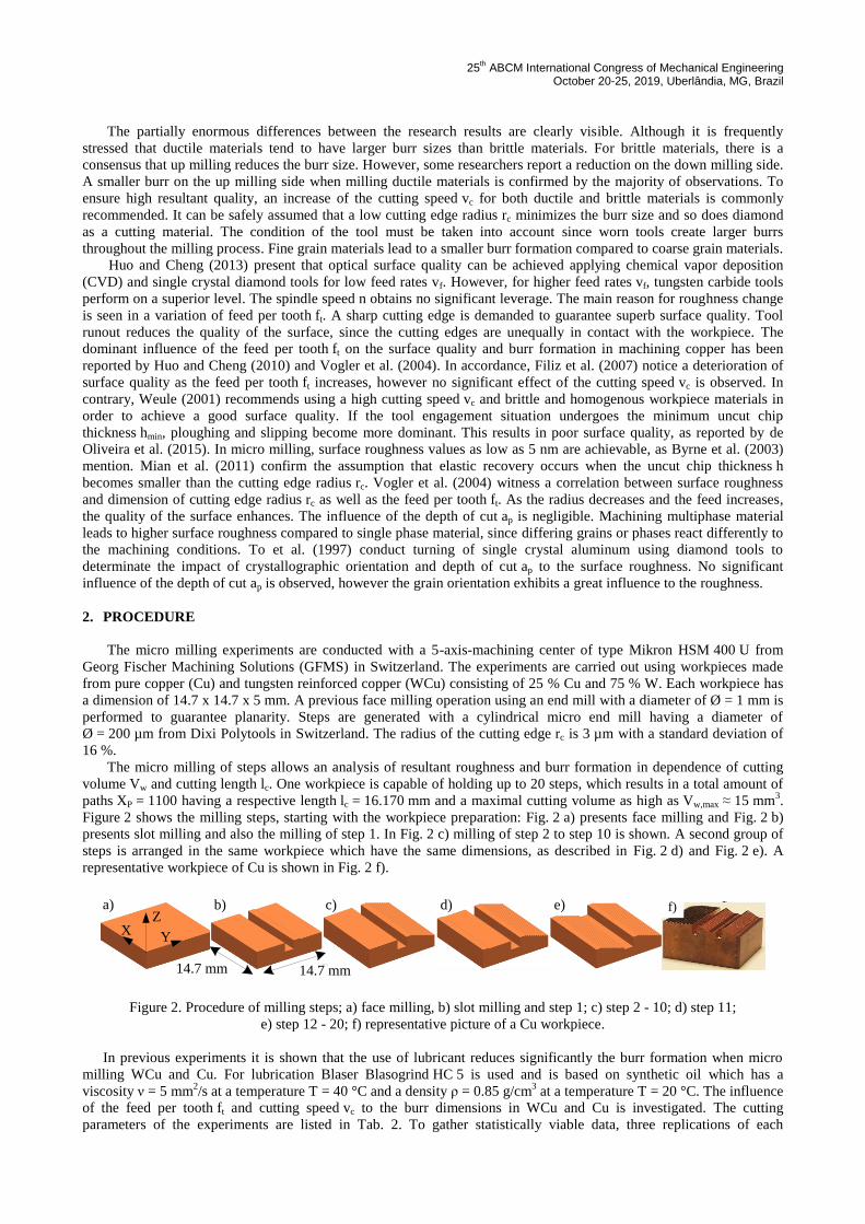
Figure 2 shows the milling steps, starting with the workpiece preparation: Fig. 2 a) presents face milling and Fig. 2 b)
presents slot milling and also the milling of step 1. In Fig. 2 c) milling of step 2 to step 10 is shown. A second group of
steps is arranged in the same workpiece which have the same dimensions, as described in Fig. 2 d) and Fig. 2 e). A
representative workpiece of Cu is shown in Fig. 2 f).
a) b) c) d) e) f)
14.7 mm
Z
YX
f)
14.7 mm
Figure 2. Procedure of milling steps; a) face milling, b) slot milling and step 1; c) step 2 - 10; d) step 11;
e) step 12 - 20; f) representative picture of a Cu workpiece.
In previous experiments it is shown that the use of lubricant reduces significantly the burr formation when micro
milling WCu and Cu. For lubrication Blaser Blasogrind HC 5 is used and is based on synthetic oil which has a
viscosity ν = 5 mm2/s at a temperature T = 40 °C and a density ρ = 0.85 g/cm
3 at a temperature T = 20 °C. The influence
of the feed per tooth ft and cutting speed vc to the burr dimensions in WCu and Cu is investigated. The cutting
parameters of the experiments are listed in Tab. 2. To gather statistically viable data, three replications of each

H. Büttner, G. Vieira, M. Wiessner, K. Wegener Burr-Free Micro Milling for Electrodes in Die-Sinking EDM
parameter combination are performed. This results in a total of 48 experiments and for each experiment a new tool is
used. The lower limit of the feed per tooth is set to ft = 1 µm. The upper cutting speed vc = 125 m/min is limited due to
the maximum spindle speed nmax = 200.000 rpm. Previous parametric screening experiments revealed that a stable
process is guaranteed when selecting a width and depth of cut as low as ae = ap = 30 µm for both materials. All
experiments are performed in up milling.
Table 2. Cutting parameters and condition for micro milling Cu and WCu.
Material cutting speed
vc [m/min]
feed per tooth
ft [µm]
width of cut
ae [µm]
depth of cut
ap [µm] lubricant
Cu 60 and 125 1, 3, 10 and 15 30 30 yes
WCu 60 and 125 1, 3, 10 and 15 30 30 yes
3. EXPERIMENTS
3.1 Burr Formation
Burr formation in micro milling has a severe detrimental implication to the products intended purpose. Deburring
mechanisms are often excluded since filigree structures can be injured and specified tolerances cannot be guaranteed.
However, the extension of burr formation can be substantially inhibited (i. e. by using appropriate process parameters,
different workpiece materials, flushing conditions, tool geometry, tool material and so on), although not ad libitum.
Material properties strongly impact formation. As reported by Beier and Nothnagel (1999) and by Ko and Dornfeld
(1991) ductile materials indicate a higher tendency towards burr formation than brittle materials. Wu et al. (2017)
observe burr reduction when copper is machined at a lower feed per tooth ft. Minimum burr size is observed on the up
milling side. Kim et al. (2014) and Piquard et al. (2013) describe burr reduction for brittle materials when the feed per
tooth ft is increased. The size of the entrance and exit burr throughout the experiments is found to be small or nonexistent and thus these
burrs are neglected. The bottom side burr is removed by subsequent milling passes of the following step. However, the
formation and dimensions of the Poisson burr, as shown in Fig. 1 b) and highlighted in red, is in the scope of
investigation. The average burr height HB and average burr width WB are measured along the edge of the steps to
quantitatively investigate the relationship between cutting conditions and burr formation.
To analyze the burr formation, a 3D-scan is performed using an Alicona InfiniteFocus microscope. Fig. 2
demonstrates the procedure of the burr measurement. As shown in Fig. 3 a), the 3D-scan is arranged in such a way that
the bottom of the machined step (I), a relatively large surface of the pre-machined surface (II) and the burr formation
(III) are in focus. Using a Matlab script, the burr structure can be separated for further analysis. A reference plane
highlighted in red is introduced on the pre-machined surface (II) in order to distinguish the burr structure and the pre-
machined surface, as presented in Fig. 3 b). This allows a color coding of the measured z-values. Also, the reference
plane defines the zero level and aligns the machined surface in the X-Y-plane. Due to the small dimensions of the burr
in micrometer range, the surface topography needs to be considered. In Fig. 3 c) the topography is filtered and the
adjusted reference plane is presented and highlighted in blue. The evaluation of burr dimension is feasible by separating
the burr structure from the machined surface using the adjusted reference plane, as shown in Fig. 3 d). The maximum
height (IV) and width (V) of the burr formation per path are marked in the plot. Based on this, averaged values and
corresponding standard deviations of the burr width WB and burr height HB can be calculated.
a)
(I)
(III)
500 µm
X
Y
Z
(II)
b) c)c)
- 20 µm
- 10 µm
0 µm
10 µm
20 µm
30 µm d)
(V)
(IV)
- 20 µm
- 10 µm
0 µm
10 µm
20 µm
30 µm
500 µm
500 µm
X
YZ
WB
Figure 3. Procedure of burr measurement; a) 3D optical imaging; b) reference plane fit; c) filtering of topography;
d) free cut of burr: projected burr surface area AB,prj, height HB and width of burr WB.
Burr formation is highly sensitive to tool wear, thus the burr measurement is restricted from step 1…4 for each
workpiece. This respectively, results in a material removal of Vw = 4.5 mm3 per workpiece. In Fig. 4 a) and b) the
width WB and height HB of the burrs are shown for a cutting speed of vc = 60 m/min and vc = 125 m/min. For each case,
the burr expands more laterally than in the height direction. The ratio λ of the width of the burr WB to the height of the
burr HB is 1.95±0.25.

25th ABCM International Congress of Mechanical Engineering
October 20-25, 2019, Uberlândia, MG, Brazil
0
50000
100000
150000
200000
250000
300000
350000
1 3 10 15
pro
ject
ed s
urf
ace
are
a [
µm
2]
feed per tooth ft [µm]
projected surface area
vc = 125 m/min (WCu) vc = 60 m/min (WCu)
vc = 125 m/min (Cu) vc = 60 m/min (Cu)
vc
vc
vc
vc
0
5
10
15
20
25
30
35
1 3 10 15
bu
rr s
ize [
µm
]
feed per tooth ft [µm]
vc = 60 m/min
0
5
10
15
20
25
30
35
1 3 10 15
bu
rr s
ize [
µm
]
feed per tooth ft [µm]
Height; WCu Width; WCu Height; Cu Width; Cu
0
5
10
15
20
25
30
35
1 3 10 15
bu
rr s
ize [
µm
]
feed per tooth ft [µm]
vc = 125 m/mina) b)
c)
Figure 4. Burr formation in micro milling Cu and WCu; a) width WB and Height HB of burr when using a cutting
speed vc = 60 m/min; b) width WB and Height HB of burr when using a cutting speed vc = 125 m/min.
Figure 5 presents the influences of the feed per tooth ft and cutting speed vc on the burr formation of WCu and Cu.
To enhance comparability, the projected burr surface area AB,prj is calculated. For both materials, an opposite behavior is
detected: when increasing the feed per tooth ft during machining Cu, the burr size increases, whereas the burr size of
WCu decreases. The cutting speed vc also reveals a significant influence to the burr size. For machining WCu, it can be
assumed that the strain hardening effect introduced by high cutting speed vc and feed per tooth ft dominates over the
thermal softening effect. In this case, the material undergoes hardening leading to shearing rather than plastic
deformation. In the case of machining Cu, the thermal softening effect is the dominating factor. At high cutting speed vc
and high feed per tooth ft the generated local heat cannot be completely dissipated by the thermal conductivity of Cu
and the lubricant. Choosing improper machining parameters not only leads to larger burr dimensions, but also leads to
higher standard deviations of the burr dimensions. The material to be removed cannot be entirely cut and is rather
plastically deformed. This results in discontinuous and a partially extreme large burr size.
0
50000
100000
150000
200000
250000
300000
350000
1 3 10 15
pro
jecte
d b
urr
su
rfa
ce
are
a A
B,p
rj[µ
m2]
feed per tooth ft [µm]
vc = 125 m/min (WCu) vc = 60 m/min (WCu)
vc = 125 m/min (Cu) vc = 60 m/min (Cu)
vc =
vc
vc
vc
300 µm 300 µm
projected burr surface area AB,prj
vc =
vc =
vc =
Figure 5. Evaluation of the projected burr surface area AB,prj measured along 4 steps
resulting in a total length of 60 mm and section top view images of the steps.

H. Büttner, G. Vieira, M. Wiessner, K. Wegener Burr-Free Micro Milling for Electrodes in Die-Sinking EDM
3.2 Roughness
In Fig. 6 a), the influence of the machining parameters when machining Cu and WCu to the roughness Ra is shown
under lubricated conditions. The roughness Ra is measured using a tactile measuring device from Taylor Hobson
according to DIN ISO 4287/88. Due to the reflectivity of the surfaces, optical measurement is impossible.
Measurements are performed on each of the 20 steps per specimen in order to gather sufficient statistical data. The feed
per tooth ft reveals a major impact on the roughness Ra. As the feed ft increases, the roughness Ra increases when
milling Cu and WCu. Due to the increase of process forces at higher feed per tooth ft, a larger deflection of the tool and
a larger kinematic roughness Rkin have to be assumed. No significant influence on the cutting speed vc is detected in
either case. Due to the inhomogeneity, WCu exhibits for each case a larger roughness Ra compared to Cu. Having a
speed vc = 125 m/min and a feed ft = 5 µm, the lubricant reduces the roughness Ra by 40 % for WCu to Ra = 0.043 µm
and by 27 % for Cu to Ra = 0.031 µm. The tool condition exposes no significant influence to the roughness Ra.
Throughout a total cutting length lc = 16.170 mm in WCu and Cu, the roughness Ra remains in a deviation of ±5 % for
Cu and ±10 % for WCu. Thus, the tool wear has a minor impact.
0.00
0.02
0.04
0.06
0.08
0.10
1 3 10 15
rou
gh
ness
Ra [μ
m]
feed per tooth ft [μm]
roughness Ra: WCu and Cu for vc = 60 m/min and vc = 125 m/min
WCu; vc = 125 m/min WCu; vc = 56 m/min Cu; vc = 125 m/min Cu; vc = 56 m/minvc vc vc vc
b) c)
50 µm20 µm
50 µm20 µm
I
II
III
a)
Figure 6. Evaluation of the roughness Ra when micro milling Cu and WCu; a) roughness Ra in relation to the feed per
tooth ft and the cutting speed vc; b) plastic deformation in nano scale when micro milling Cu, c) grain pull-out and
spring back effect when micro milling WCu.
Figure 6 b) presents the surface when micro milling Cu. Due to the ductility, plastic deformation in nanometer scale
is detected, as marked with (I). However, the homogeneity of Cu guarantees a low roughness Ra. In Fig. 6 c) fewer
plastic deformations at the surface are present and the two phases of WCu are recognizable. The darker areas represent
Cu, whereas the brighter areas represent W. Due to the inhomogeneity, partial grain pull-out occurs, as marked with
(II). The ductile Cu is removed primarily during milling and the brittle W has a greater resistance against cutting, as
marked with (III). Also, both elements exhibit different modulus of elasticities. Consequently, the spring back effect
behaves disparately.
The influence of multi-phase to the surface structure in micro cutting is explained by Simoneau et al. (2006). By
machining the dual phase structured AISI 1045 steel, consisting of soft ferrite and hard pearlite grains, dimples occur at
the transition of the hard to soft grain. However, no dimples occur at the transition of the soft to hard boundary. This
can be explained by the cutting energy dissipation in the region of the cutting edge. Harder grains do not absorb the
energy, but rather the energy evolves inside the softer, upcoming grain. The formation of dimples happens along the
cutting direction. It is shown that the harder grains deform in a lower magnitude than the softer grains. In many cases,
the softer grains get pulled out whereas the harder grains remain in the latter and are being cut.

25th ABCM International Congress of Mechanical Engineering
October 20-25, 2019, Uberlândia, MG, Brazil
3.3 Microstructural Alternations
The types of microstructural alternations introduced during material removal are classified by Field et al. (1989) as
mechanical, metallurgical, chemical, thermal and electrical. In the case of milling, the alternations are mainly caused by
mechanical, metallurgical and thermal loads. The principal alternations are a change in hardness and in residual stress.
Navas et al. (2008) observe a variation of hardness when turning AISI O1 steel as the tool undergoes wear. A lower
hardness is reached, when machining the same material using wire-EDM. Contrary to expectations, Hashimoto et al.
(2006) are unable to establish any association between the cutting parameters and machining conditions in comparison
to the micro hardness when milling AISI H13 steel. This result is supported by Sharman et al. (2008) in the case of
negligible tool wear during milling Inconel 718. Additionally, supplying lubrication during machining does not promote
any significant variation in hardness. Only a sufficiently high amount of plastic deformation causes an increase of
hardness. Additionally, Guo and Sahni (2004) explain that the increase of steel hardness is introduced by the occurrence
of a white layer at the surface.
Due to a higher material removal rate in macro milling compared to micro milling, a different material response
during machining can be assumed. Besides the conditions of the milling procedure and of the tool, the manufacturing
methods and mechanical properties of the material are also crucial factors. Cu is manufactured by extrusion and exhibits
a base hardness of 70 HV 0.1 and WCu is manufactured by sintering and 190 HV 0.1. In order to investigate the
influence of the material removal rate to the hardness, the cutting speed vc = 125 m/min and feed per tooth ft = 3 µm are
kept constant for each milling procedure. However, the width of cut ae and depth of cut ap are varied. The hardness is
measured according to Vickers HV 0.1 on the machined surface for each parameter combination using a load of 0.98 N.
For statistical purposes each measurement is repeated 5 times. In preliminary evaluations, no influence of the tool wear
to the hardness could be identified. Throughout one experiment, the hardness varies up to 14 % in WCu and up to 10 %
in Cu. Before milling, each specimen was wire-cut using EDM. As a reference, both materials are analyzed after being
cut using wire-EDM and without milling. Figure 7 a) presents the variation of micro hardness. No significant difference
in the micro milling scale between removing material having ae = 30 µm and ap = 30 µm to ae = 60 µm and ap = 60 µm
can be found in either material. However, by increasing the material removal to ae = 500 µm and ap = 500 µm using a
tool diameter Ø = 1 mm, a clear difference between macro and micro milling is observed as the hardness rises. A
comparison to wire-cutting demonstrates that EDM has a lower hardness.
0
50
100
150
200
250
300
350
Ha
rdn
ess
HV
0.1
-250
-200
-150
-100
-50
0
50
100
150
Res
idiu
al
Str
ess σ
[MP
a]
Micro; ae = 30 & ap = 30 µm; Cu; Ø = 200 µmMicro; ae = 60 & ap = 60 µm; Cu; Ø = 200 µmMacro; ae = 500 & ap = 500 µm; Cu; Ø = 1 mm
Micro; ae = 30 & ap = 30 µm; WCu; Ø = 200 µmMicro; ae = 60 & ap = 60 µm; WCu; Ø = 200 µmMacro; ae = 500 & ap = 500 µm; WCu; Ø = 1 mm
Wire-EDM; Cu Wire-EDM; WCu
a) b)
70
190
Figure 7. Microstructural alternations when micro milling Cu and WCu; a) variation of hardness in relation to material
removal rate and machining process; b) variation of residual stress in relation to material
removal rate and machining process.
Abrão et al. (2011) mention that a combination of mechanical and thermal loads induce residual stress.
Compressive residual stress is provoked by mechanical interferences as a result of plastic deformation. In contrast,
thermal effects lead to tensile residual stresses below the machined surface. Javidi et al. (2008), Choi (2009), Gunnberg
et al. (2006) and Xueping et al. (2009) indicate compressive residual stress when machining steel. However, Jacobson et
al. (2002) observe a growth of tensile residual stress when turning bainitic steel. This effect is explained due to an
increase of the temperature in the contact zone as the cutting speed vc adapts higher values. Guo and Sahni (2004)
investigate the impact of machining parameters on the residual stress during milling AISI H13 steel. Significant
compressive residual stress is introduced by a variation of cutting speed vc and feed rate vf. In contrary to milling and

H. Büttner, G. Vieira, M. Wiessner, K. Wegener Burr-Free Micro Milling for Electrodes in Die-Sinking EDM
turning, which cause compressive residual stresses, thermal processes lead to tensile residual stresses, as explained by
Abrão et al. (2011).
Using an X-ray diffractometer (XRD) of the type XStress 3000 G3 the direct measurement of the residual stress is
possible for multi-crystalline materials. Knowing the crystal-structure and characteristic wavelength of the X-ray tube,
diffraction angles are chosen to determine whether the workpiece surface exhibits tensile or compressive stress. This
method is suitable to undertake precise measurements in a depth as low as 10 µm. The measurements are performed
lengthways and crossways to the milling direction. Figure 7 b) clarifies that a distinction between macro and micro
milling as well as wire-EDM must be drawn. Due to a larger material removal, the cutting forces in macro milling adapt
higher values. Thus, the material at the surface is exposed to higher loads. However, as milling causes plastic
deformation, compressive residual stress is introduced whereas in wire-EDM mainly thermal effects result into material
removal and provoke tensile residual stress. The structure of the material defines to a high extent the material response
to an introduced load. WCu is less susceptible to cutting forces throughout milling. In sintered materials, compressive
residual stresses are relieved effectively. In Cu however, the higher the material removal rate becomes, the higher the
residual stress. The impact of micro and macro milling is unambiguously observed by comparing the results to the wire-
cut surface. As the specimens are pre-threatened using wire-EDM, a change from tensile to compressive stress is
observed in subsequent milling operations.
In respect to the measurements, there is a direct causal link between hardness and residual stress. As high
mechanical loads result in large plastic deformations, milling causes an increase in hardness and residual stress for both
materials. However, applying thermal loads in wire-EDM introduces tensile stress in a smaller magnitude. In this case,
the hardness adapts the lowest values.
4. CONCLUSIONS
When milling in micro scale, the process and the material response behave differently to milling in macro scale. In
precise micro manufacturing high demands on workpiece quality and form accuracy are placed. For instance, no burr
formation is admitted when micro structuring electrodes for subsequent die-sinking EDM. Burrs are reproducing on an
eroded cavity, which leads to defective work results. As burr removal damages micro structures or interferes with
tolerances, optimal process parameters and conditions for burr free milling are discussed.
In this paper, an optimal micro milling process for WCu and Cu are derived in respect to burr formation, roughness,
hardness and residual stress. It is shown that both materials behave differently as Cu is ductile and WCu is brittle. Micro
milling experiments using a tool with a diameter as low as Ø = 200 µm are conducted. Due to the limitation of the
spindle speed of n = 200.000 rpm, the cutting speed is defined to vc = 60 and 125 m/min. Previous experiments reveal
that the use of lubricant drastically reduces burr formation and roughness Ra. To compare the hardness and residual
stress, macro milling using a tool with a diameter as low as Ø = 1 mm is performed. The results are summarized as
follows:
To analyze and compare Poisson burrs when micro milling Cu and WCu, the burr height HB, burr width WB
and the projected surface area AB,prj of the burrs are measured. In each case, the width of the burr WB adapts
higher values compared to the height of the burrs HB. The ratio λ of the width of the burr WB to the height of
the burr HB is 1.95±0.25. Due to the inhomogeneity of WCu, the standard deviation adapts higher values. The
variation of the feed per tooth ft has the greatest influence on the burr size; however, for both materials the case
is opposite: as the feed per tooth is reduced to ft = 1 µm WCu, shows the smallest burr. Whereas for ft = 15 µm,
Cu performs the best. Due to the higher hardness, WCu tends to have less burr formation with a minimum
projected burr surface area AB,prj = 9.000 µm2. In comparison, when milling Cu with favorable parameters, a
minimum projected burr surface area AB,prj = 60.000 µm2 can be reached.
As the feed per tooth ft increases, the roughness Ra for both materials worsens. Due to the inhomogeneity of
WCu and the partial grain pull-out, the roughness Ra tends to be higher compared to Cu. No influence due to
tool wear is detected. The impact of the cutting speed vc is found to be negligible.
The hardness and residual stresses of Cu and WCu is mainly affected by the material removal rate and the
machining process. An unambiguous relation between micro and macro milling is presented. Removing
material with ae = 30 µm and ap = 30 µm while having a tool diameter Ø = 200 µm, results in less residual
stress and lower hardness in comparison to as milling in the macro scale having ae = 500 µm and ap = 500 µm
with a tool diameter Ø = 1 mm. Each specimen is wire-cut; therefore, initially tensile stress predominates.
After milling however, compressive stress is introduced. A correlation between the stress and hardness can also
be derived: as the residual stress changes the hardness changes.

25th ABCM International Congress of Mechanical Engineering
October 20-25, 2019, Uberlândia, MG, Brazil
5. REFERENCES
Abrão, A. M., Ribeiro, J. L. S. and Davim, J. P., 2011: Machining of Hard Materials. Springer.
Avila, M. and Dornfeld, D., 2004. On The Face Milling Burr Formation Mechanisms and Minimization Strategies at
High Tool Engagement. Proceedings of the 7th International Conference on Deburring and Edge Finishing,
Berkley, 191–200.
Bajpai, V., Kushwaha, A. K. and Singh, R. K., 2013. Burr formation and surface quality in high speed micro milling of
titanium alloy (Ti6Al4V). Proced ASME Int Manuf Sci Eng Conf, Wisconsin, USA.
Beier, H. M. and Nothnagel, R., 1999: Handbuch Entgrattechnik: Wegweiser zur Gratminimierung und Gratbeseitigung
für Konstruktion und Fertigung. Hanser Verlag.
Biermann, D., Schlenker, J. and Steiner, M., 2012. Oberflächenqualität beim Mikrofräsen. wt Werkstattstechnik online
102.
Byrne, G., Dornfeld, D. and Denkena, B., 2003. Advancing Cutting Technology. CIRP Annals – Manufact. Technol.,
52, 483.
Choi, Y., 2009. A study on the effects of machining-induced residual stress on rolling contact fatigue. Int J Fatigue, 31,
1517–1523.
da Silva, L. C., da Mota, P. R., Bacci da Silva, M., Ezugwu, E. and Machado, A. R., 2015. Study of burr height in face
milling of PH 13-8 Mo stainless steel––Transition from primary to secondary burr and benefits of deburring
between passes. CIRP Journal of Manufacturing Science and Technology, 61-67.
de Oliveira, F. B., Rodrigues, A. R., Coelho, R. T. and de Souza, A. F., 2015. Size effect and minimum chip thickness
in micromilling. International Journal of Machine Tools and Manufacture, 89, 39-54.
de Souza Junior, A., Sales, W., Ezugwu, E., Bonney, J. and Machado, A., 2003. Burr Formation in Face Milling of Cast
Iron with Different Milling Cutter Systems. Proceedings of the Institution of Mechanical Engineers Part B
Journal of Engineering Manufacture 217, 1589–1596.
Field, M., Kahles, J. F. and Koster, W. P., 1989: Metals handbook.
Filiz, S., Conley, C. M., Wasserman, M. B. and Ozdoganlar, O. B., 2007. An experimental investigation of micro-
machinability of copper 101 using tungsten carbide micro-endmills. International Journal of Machine Tools
and Manufacture, 47, 1088-1100.
Gillespie, L. K. and Blotter, P. T., 1976. The Formation and Properties of Machining Burrs. Transactions of ASME
Journal of Engineers for Industry 98, 66–74.
Gunnberg, F., Escursell, M. and Jacobson, M., 2006. The influence of cutting parameters on residual stresses and
surface topography during hard turning of 18MnCr5 case carburised steel. J Mater Process Technol, 174, 82-
90.
Guo, Y. B. and Sahni, J., 2004. comparative study of hard turned and cylindrically ground white layers. Int J Mach
Tools Manuf, 44, 135-145.
Hartnett, J., Min, S. and Dornfeld, D., 2007. Micromachining and Burr Formation for Precision Mechanical
Components. Proceedings of MTTRF, 231-236.
Hashimoto, A. W., Guo, Y. B. and Warren, A. W., 2006. Surface integrity difference between hard turned and ground
surfaces and its impact on fatigue life. CIRP Ann Manuf Technol, 55, 81-84.
Huo, D. and Cheng, K., 2010. Experimental investigation on micromilling of oxygen-free, high-conductivity copper
using tungsten carbide, chemistry vapour deposition, and single-crystal diamond micro tools. Proce Inst Mech
Eng Part B J Eng Manuf, 224, 995–1003.
Huo, D. and Cheng, K., 2013: Micro-Cutting: Fundamentals and Applications. Wiley.
Jacobson, M., Dahlmann, P. and Gunnberg, F., 2002. Cutting speed influence on surface integrity of hard turned bainite
steel. J Mater Process Technol, 128, 318–323.
Javidi, A., Rieger, U. and Eichlseder, W., 2008. The effect of machining on the surface integrity and fatigue life. Int J
Fatigue 30, 10-11.
Jones, S. and Furness, R., 1997. An Experimental Study of Burr Formation for Face Milling 356 Aluminium.
Transactions of NAMRI/SME 25, 183–188.
Kim, D. H., Lee, P. H., Kim, J. S., Moon, H. and Lee, S. W., 2014. Experimental Study On Micro End-Milling Process
Of Ti-6al-4v Using Nanofluid Minimum Quantity Lubrication (MQL). Proceedings of the ASME 2014
International Manufacturing Science and Engineering Conference.
Ko, S. L. and Dornfeld, D. A., 1991. A study on burr formation mechanism. Transactions of the ASME Journal of
Engineering Materials and Technology 113, 75-87.
Kumar, S. and Dornfeld, D., 2003. Basic Approach to a Prediction System for Burr Formation in Face Milling. Journal
of Manufacturing Processes, 5.
Lee, K., Essel, I. and Dornfeld, D., 2001. Burr formation in micro milling. University of California at Berkeley,
Berkeley, CA, 10-15.
Mian, A. J., Driver, N. and Mativenga, P. T., 2011. Identification of factors that dominate size effect in micro-
machining. Int J Mach Tools Manuf, 383–394.
H. Büttner, G. Vieira, M. Wiessner, K. Wegener Burr-Free Micro Milling for Electrodes in Die-Sinking EDM
Navas, G., Ferreres, I., Marañón, J. A., García-Rosales, C. and Gíl Sevillano, J., 2008. White layers generated in AISI
O1 tool steel by hard turning or by EDM. Int J Mach Mach Mater, 4, 287-301.
Piquard, R., D’Acunto, A., Laheurte, P. and Dudzinski, D., 2013. Micro-end milling of NiTi biomedical alloys, burr
formation andphase transformation. Precision Engineering.
Reichenbach, I. G., Bohley, M., Sousa, F. J. P. and Aurich, J. C., 2018. Micromachining of PMMA—manufacturing of
burr-free structures with single-edge ultra-small micro end mills. The International Journal of Advanced
Manufacturing Technology, 96, 3665-3677.
Saptaji, K., Subbiah, S. and Dhupia, J. S., 2012. Effect of side edge angle and effective rake angle on top burrs in
micro-milling. Precision Engineering 36, 444– 450.
Sharman, A. R. C., Hughes, J. I. and Ridgway, K., 2008. Tool life and surface integrity aspects when drilling and hole
making in Inconel 718. Mater Process Technol, 200, 424-432.
Simoneau, A., Ng, E. and Elbestawi, M. A., 2006. Surface defects during microcutting. International Journal of
Machine Tools and Manufacture, 46, 1378-1387.
Thilow, A., Berger, K., Prüller, H., Maier, R., Przyklenk, K., Schäfer, F. and Pießlinger-Schweiger, S., 2005: Entgrat-
Technik. Entwicklungsstand und Problemlösungen. expert Verlag.
To, S., Lee, W. B. and Chan, C. Y., 1997. Ultraprecision Diamond Turning of Aluminum Single Crystals. J. Mater.
Process. Technol., 63, 157–162.
Vogler, M. P., Devor, R. E., Kapoor, S. G. and Asme, F., 2004: On the Modeling and Analysis of Machining
Performance in Micro-Endmilling, Part I: Surface Generation.
Wang, G. C. and Zhang, C. Y., 2004. Mechanism of Burr Formation in Milling Key Engineering Materials, 278-281.
Weule, H. H., V.; Tritschler, H., 2001. Microcutting of Steel to Meet New Requirements in Miniaturisation. Annals of
the CIRP 50
Wu, X., Li, L. and He, N., 2017. Investigation on the burr formation mechanism in microcutting. Precision Eng 191–
196.
Xueping, Z., Erwei, G. and Liu, C. R., 2009. Optimization of the process parameter of residual stresses for hard turned
surfaces. J Mater Process Technol, 209, 4286–4291.
6. RESPONSIBILITY NOTE
The author(s) is (are) the only responsible for the printed material included in this paper.