Embed Size (px)
Citation preview

LSI ER-319-24
CO, R E M O V A L AND WATER RECOVERY
(BAS A-CP- 160317) EXTENDED DURATXCH ORBITER N80-10800 STUDY: C 0 2 R E H O V A L AND WATER RECOVERY Final Report ( l i f e Systems. Inc.. C l e v e l a n d , Ohio.) 9 1 p " C AOS/Flf A01 CSCL 06K 9nclas G3/54 45856
FINAL REPORT
R . D. Marshall, G. S. Ellis, F. H. Schubert and R. A. Wynveen
May, 1979
Prepared Under Contract NAS9-15218
by
lye S y s ~ ~ s , k. Cleveland, OH 44122
for
LYNDON B. JOHNSbN SPACE CENTER National Aeronautics and Space Administration

EXTENDED DURATION ORBITER STUDY: C02 REMOVAL AND WATER RECOVERY
FINAL REPORT
R. D . Marshall, G . S . E l l i s , F . H . Schubert and R. A. Wynveen
May, 1979
Prepared Under Contract NAS9-15218
LIFE SYSTEMS, INC. Cleveland, OH 44122
for
Lyndon B, Johnson Space Center National Aeronautics and Space Admlnietration
FOREWORD
The work descr ibed h e r e i n was conducted by L i f e Systems, Inc . f o r t h e Nat ional Aeronautics and Space Adminis t ra t ion, Lyndon B. Johnson Space Center i n accordance wi th t h e requirements of Contract NAS9-15218. The o b j e c t i v e of t h e program was t o eva lua te t h e Electrochemical Depolarized Carbon Dioxide Concentra tor and t h e Vapor Compression D i s t i l l a t i o n Subsystem f o r Extended Durat ion O r b i t e r a p p l i c a t i o n . The per iod of performance f o r t h e program was A p r i l , 1978 t o May, 1979.
The o v e r a l l Program Manager f o r t h e c o n t r a c t was F. H. Schubert wi th t h e Extended Duration O r b i t e r s tudy a c t i v i t i e s d i r e c t e d by R . D . Marshal l . Tech- n i c a l suppor t f o r t h e Extended Duration O r b i t e r s tudy was provided by G. S. E l l i s and D r . R . A . Wynveen.
The c o n t r a c t Technical Monitor was Mr. Nick Lance, J r . , Crew Systems Div i s ion , Lyndon F. Johnson Space Center , Houston, TX 77058.
A l l measurements and c a l c u l a t i o n s conta ined wi th in t h i s r e p o r t a r e expressed i n SI (met r i c ) u n i t s ; convent ional u n i t s a r e given i n p a r e n t h e s i s .
The au thors wish t o acknowledge t h e important t ec lmica l c o n t r i b u t i o n s and program guidance o f f e r e d by t h e personnel of Crew Systems Div i s ion , NASA Johnson Space Center , i n p a r t i c u l a r N . Lance, F. H. Samonski, D. W. Morr is , J r . and W . F. Reveley and t h e personnel of t h e O r b i t e r Environmental Cont ro l l L i f e Support Systems Group, Advanced S h u t t l e P r o j e c t s Department of Rockwell I n t e r n a t i o n a l , i n p a r t i c u l a r J. W. Gibb, 0. T. S t o l l , G . E . Laubach, A. L. Jones and D . C . Gore.

TABLE OF CONTENTS
PAGE - LIST OF FIGURES . . . . . . . . . . . . . . . . . . . . . . . . . . . . iii
LIST OF TABLES . . . . . . . . . . . . . . . . . . . . . . . . . . . . iv
LIST OF ACRONYMS . . . . . . . . . . . . . . . . . . . . . . . . . . . i.v
SUMMARY. . . . . . . . . . . . . . . . . . . . . . . . . . . . . . . . 1
INTRODUCTION . . . . . . . . . . . . . . . . . . . . . . . . . . . . . 2
Background . . . . . . . . . . . . . . . . . . . . . . . . . . . . 2
Electrochemical CO Removal . . . . . . . . . . . . . . . . . Vapor Compression aistillation for Water Recovery . . . . . .
Study Method . . . . . . . . . . . . . . . . . . . . . . . . . . . 4
Ground Rules . . . . . . . . . . . . . . . . . . . . . . . . Mission Options . . . . . . . . . . . . . . . . . . . . . . .
Program Organization . . . . . . . . . . . . . . . . . . . . . . . 9
CARBON DIOXIDE REMOVAL SUBSYSTEM . . . . . . . . . . . . . . . . . . . 9
EDC Flight Concept . . . . . . . . . . . . . . . . . . . . . . . . 13
Subsystem Description . . . . . . . . . . . . . . . . . . . . 13 Packaging . . . . . . . . . . . . . . . . . . . . . . . . . . 19 Subsystem Characteristics . . . . . . . . . . . . . . . . . . 19 Vehicle Integration . . . . . . . . . . . . . . . . . . . . . 19 Development Status . . . . . . . . . . . . . . . . . . . . . 24
EDC/WVE Flight Concept . . . . . . . . . . . . . . . . . . . . . . 24
Subsystem Description . . . . . . . . . . . . . . . . . . . . 2 4 !jackaging . . . . . . . . . . . . . . . . . . . . . . . . . . 29 Subsystem Characteristics . . . . . . . . . . . . . . . . . . 29 Vehicle Integration . . . . . . . . . . . . . . . . . . . . . 34 Development Status . . . . . . . . . . . . . . . . . . . . . 34
C02 Removal Subsystems Compariron . . . . . . . . . . . . . . . . 34
Mission Option One . . . . . . . . . . . . . . . . . . . . . 40 Mission Option Two . . . . . . . . . . . . . . . . . . . . . 40 Mission Option Three . . . . . . . . . . . . . . . . . . . . 40
CO Removal Subsystem Evaluation Conclusions . . . . . . . . . . . 40 2
continued-

Table of Contents - continued PAGE - 4
45 b
45
WATER RECOVERY SUBSYSTEM . . . . . . . . . . . . . . . . . . . . . . . VCDS Flight Concept . . . . . . . . . . . . . . . . . . . . . . .
Subsystem Description . . . . . . . . . . . . . . . . . . . . Packaging . . . . . . . . . . . . . . . . . . . . . . . . . . Subsystem Characteristics . . . . . . . . . . . . . . . . . . Vehicle Integration for Supplementary Heat Rejection . . . . Vehicle Integration for Potable Water . . . . . . . . . . . . Development Status . . . . . . . . . . . . . . . . . . . . .
Wi ..er Recovery Subsystem Comparison . . . . . . . . . . . . . . . Mission Option Two . . . . . . . . . . . . . . . . . . . . . Mission Option Three . . . . . . . . . . . . . . . . . . . .
. . . . . . . . . . Water Recovery Subystem Evaluation Conclusions
COPIEINED C02 REMOVAL AND WATER RECOVERY . . . . .
. . . . . . . . . . . . . . . . . . . . . . . . Mission Option Two
Condensate Recovery . . . . . . . . . . . . . . . . . . . . . Total Water Recovery . . . . . . . . . . . . . . . . . . . .
. . . . . . . . . . . . . . . . . . . . . . . Mission Option Three
. . . . . . . . . . . . . . . . . . . . . . . . . . . . . . CONCLUSIONS
RECOMMENDATIONS . . . . . . . . . . . . . . . . . . . . . . . . . . . . REFERENCES . . . . . . . . . . . . . . . . . . . . . . . . . . . . . .
. . . . . . . . . . . . . APPENDIX 1 SHUTTLE AIR-COOLED EDC SUBSYSTEM
. . . . . . . . . . . APPENDIX 2 SHUTTLE AIR-COOLED EDCIkVE SUBSYSTEM
LIST OF FIGURES
PAGE - FI GURE
EDOStudyMethod . . . . . . . . . . . . . . . . . . . . . . . . . . . . . . . . . . . Shuttle Air Humidity Specifications . . . . . . . . . . . . Projected Shuttle Air Humidity Ranges . . . . . . . . . . . . . . . . . . . . Shuttle EDC Schematic
. . . . . . . . . . . . . . . Shuttle EDC Detailed Schematic. . . . . . . . . . . . . . . . . . . Shuttle EDC Configuration . . . . . . . . . . . . . Existing Shuttle Air Revitalization
. . . . . . . . . . . . . . . EDC Location Within Shuttle ARS . . . . . . . . . . . . . . . . Three-Person Preprototype EDC . . . . . . . . . . . . . . . . . . Shuttle EDCIWVE Schematic . . . . . . . . . . . . . Shuttle EDCIWVE Detailed Schematic.
. . . . . . . . Shuttle EDCIWVE Configuration (Seven Person). . . . . . . . . . . . . . . . . . . Shuttle EDC/WVE Location. RLSE Preprototype EDCIWVE . . . . . . . . . . . . . . . . . . C02 Removal Subsystems Launch Weight Comparison: Mission Option One. . . . . . . . . . . . . . . . . . . . . . C02 Removal Subsystems Launch Weight Comparison: Mission Option Two. . . . . . . . . . . . . . . . . . . . . . C02 Removal Subsystems Launch Weight Comparison: Mlssion Option Three. . . . . . . . . . . . . . . . . . . . . CO Removal Subsystems Equivalent Weight Comparison: ~igsion Option Three. . . . . . . . . . . . . . . . . . . . . Shuttle VCDS Schematic. . . . . . . . . . . . . . . . . . . .
. . . . . . . . . . . . . . . Shuttle VCDS Detailed Schematic . . . . . . . . . . . . . . . . . Shuttle VCDS Configuration.
Existing Shuttle Water Management Block Diagram . . . . . . . Shuttle Water Recovery Block Diagram for Supplemental HeatRejection . . . . . . . . . . . . . . . . . . . . . . . Shuttle Potable Water Recovery Block Diagram. . . . . . . . . RLSE Preprototype VCDS. . . . . . . . . . . . . . . . . . . . Water Management System Launch Weight Comparison: . . . . . . . . . . . . . . . . . . . . . Mission Option Two. Water Management System Equivalent Weight Comparison:
. . . . . . . . . . . . . . . . . . . . Mission Option Three. Combined CO Removal and Condensate Recovery: 2 Mission Option Two. . . . . . . . . . . . . . . . . . . . . . Combined C02 Removal and Water Recovery:
. . . . . . . . . . . . . . . . . . . . . Mission Option Two. Combined C02 Removal and Water Recovery:
. . . . . . . . . . . . . . . . . . . . Mission Option Three.
TABLE
1 2 3 4 5
6 7 8
9 10
11 12 13 14 15 16 17 18 19 2 0
LIST OF TABLES
Extended Duration Orbiter Design Data . . . . . . . . . . . . Enhanced Orbiter Mission Options. . . . . . . . . . . . . . . C02 Removal Subsystem Design Specifications . . . . . . . . . Shuttle EDC Module Operating Characteristics. . . . . . . . . EDC Subsystem Component Weight, Power and Heat Generation Summary. . . . . . . . . . . . . . . . . . . . . . Shuttle EDC Subsystem Characteristics S m a r y . . . . . . . . Shuttle EI)C/WVE Module Operating Characteristics. . . . . . . EDCIWVE Subsystem Component Weight, Power and Heat Generation Summary. . . . . . . . . . . . . . . . . . . . . . Shuttle EDC/WVE Subsystem Characteristics Summary . . . . . . Comparison of Shuttle CO Removal Subsysten. Characteristics:
2 Seven-Person. . . . . . . . . . . . . . . . . . . . . . . . . Expendables for Power Consumed: Seven-Persons . . . . . . . . CO Removal Subsystems' Total Mission Expendables . . . . . . V C ~ S Design Specifications . . . . . . . . . . . . . . . . . . Shuttle VCDS Operating Characteristics. . . . . . . . . . . . VCDS Component Weight, Power and Heat Generation Summary. . . Shuttle VCDS Characteristics. . . . . . . . . . . . . . . . . VCDS-Based Water Recovery System Char,~cteristics. . . . . . . VCDS-Based Potable Water Recovery System Characteristics. . . Water Management Systems Characteristics. . . . . . . . . . . Potable Water Management Systems Characteristics. . . . . . .
LIST OF ACRONYMS
ACIDD ARS CCA C/M T DAS EC/LSS EDC EDCM ED0 FCA PEP RLSE SA/BA SAIFC SSP STS VCDS WCL WMS WQM WRS WVE
. .-.....a. .
Advanced Combined Iodine Dispenser/Detector Air Revitalization Subsystem Coolant Control Assembly Control/Monitor Instrumentation Data Acquisition System Environmental Control/Life Support Subsystem Electrochemical Depolarized CO Concentrator
2 Electrochemical Depolarized C02 Concentrator Module Extended Duration Orbiter Fluid Control Assembly Power Extension Package Regenerative Life Support Evaluation Solar Array/Battery Solar Array/FueI Cell Space Station Prototype Space Transportation System Vapor Compression Distillation Subsystem Water Coolant Loop Water Management System Water Quality Monitor Water Recovery Subsystem Water Vapor Electrolysis
PAGE - t I
SUMMARY
The National Aeronautics and Space Administration i s present ly evaluat ing methods t o enhance the space Shu t t l e Orbi te r mission c a p a b i l i t i e s . S ign i f i - cant savings can be a t t a ined by r e t r c f i t t i n g the Orbi te r with a regenerable Carbon Dioxide Removal Subsystem and a Water Recovery System. The Electro- chemical Depolarized Carbon Dioxide Concentrator f o r carbon dioxide removal and the Vapor Compression D i s t i l l a t i o n Subsystem f o r water recovery were evaluated f o r Extended Duration Orbi te r missions.
The Electrochenical Depolarized Carbon Dioxide Concentrator i s an advanced carbon dioxide removal concept t h a t can o f f e r s i g n i f i c a n t weight savings through reduced expendables f o r projected etfanced capab i l i t y Orbi te r missions. The Electrochemical Depolarized Carbon Dioxide Concentrator can be in tegra ted with ex i s t i ng Shu t t l e resources o r , a s mission p r o f i l e s requi re , combined with Water Vapor Elec t ro lys i s f o r oxygen regeneration t o fu r the r reduce mission expendables. The t w s Electrochemical Depolarized Carbon Dioxide Concentrator Subsystems were eva!dated f o r (a) the basel ine Orbi te r when expanded t o accommo- date a crew of seven (Mission Option One), (b) an Extended Duration Orbi te r with a power extension package t o reduce fue l c e l l expendables (Mission Option Two) and (c) an Extended Duration Orbi ter with a f u l l capab i l i t y power module t o el iminate fue l c e l l expendables (Mission Option Three). Weight savings a t t a inab le using the electrochemical carbon dioxide removal concept versus basel ine l i thium hydroxide a r e 59 kg (130 l b ) , 218 kg (480 l b ) and 363 kg (800 l b ) , respec t ive ly , f o r the three mission options evaluated.
The Electrochemical Depolarized Carbon Dioxide Concentrator was a l s o compared t o the s o l i d amine regenerable carbon dioxide removal concept f o r t he three enhanced Orbi ter mission options evaluated. The electrochemical technique was se lec ted f o r a l l t h r ee missions s ince it had 5 t o 55% lower weight, 50% lower power and was the lowest weight carbon dioxide removal concept f o r each mission.
The Vapor Compression D i s t i l l a t i o n Subsystem can reclaim wastewater f o r use i n the Shut t le f l a sh evapor,ztors f o r supplementary heat r e j ec t ion , o r , when combined with addi t iona l Water Management System components, can produce potable water a s w i l l be required f o r missions when fue l c e l l s a r e not used f o r power generation. Water recovery i s not required f o r Mission Option One s ince s u f f i c i e n t water is generated by the fue l c e l l s . The Vapor Compression D i s t i l l a t i o n Subsystem was evaluated f o r Mission Options Two and Three only. Weight savings of 696 kg (1,533 l b ) and 1,092 kg (2,405 l b ) , r e ~ p e c t i v e l y , a r e a t t a inab le using the Vapor Compression D i s t i l l a t i o n Subsystem f o r water re- covery versus on-board water s torage.
Combined carbon dioxide removal and water recovery was evaluated t o determine the a f f e c t on regenerable carbon dioxide removal subsystem se l ec t ion . Mission Option One was not considered s ince water recovery i s not required. For Mission Option Two, two l eve l s of water recovery f o r supplemental heat re jec- t i o n were considered: condensate recovery only and t o t a l water recovery (conden- s a t e , ur ine and wash water). The Electrochemical Depolarized Carbon Dioxide Concentrator Subsystem had weight savings of 61 kg (134 l b ) and 64 kg (141 l b ) , respect ively, over the s o l i d amine and Electrochemical Depolarized Carbon Dioxide Concentrator/Water Vapor E lec t ro lys i s Subsystems. For Mission Option
Three total water recovery was considered to meet potable water requirements. The weight savings obtained using the Electrochemical Depolarized Carbon Dioxide Concentrator Subsystem versus the solid amine was 331 kg (729 lb) . The combined functions of carbon dioxide removal and water recwery favored the Electrochemical Depolarized Carbon Dioxide Concentrator concept since it generates additional water, in the form of condensate, as part of the carbon dioxide removal process.
INTRODUCTION
The National Aeronautics and Space Administration (NASA) is presep~~~~evaluat- ing methods to extend the Space Shuttle Orbiter Mission Duration. Two changes in the existing orbiter Environmental Control and Life Support Systen (EC/LSS) are desirable. The first is to replace the existing lithium hydr~xide (LiOH) cartridges with a Regenerable Carbon Dioxide (C02) Removal Subsystem and the second is to reclaim waste water (urine, wash water and condensate) for supplementary heat rejection and eventually potable water requirements. To perform these functions, two subsystems have evolved through NASA sponsor- ship over the past ten years: the Electrochemical Depolarized C02 Concentrator (EDC) for C02 removal and the Vapor Conpression Distillation Subsystem (VCDS) for wastewater recovery.
The EDF7lf2)eing developed by NASA through its Contractor, Life Systems, Inc. (LSI) . The EDC can be integrated with existing Shuttle resources o further reduce expendables, combined with Water Vapor Electrolysis (WVE) . f 13LP5)
The VCDS is being developed by NASA through two contractors: Lockheed Missiles and Space Corporation and LSI. The VCDS can be used to generate water for supplementary heat rejecti~p~yr combined with an Advanced Combinff,fodine Disyenser/Detector (ACIDD) and a Water Quality Monitor (WQM) to gen- ?rate potable water. The EDC, the EDC/WVE and the VCDS have been evaluated for Shuttle application by first sizing representative subsystems and then comparing them to baseline Shuttle C02 removal and water/wastewater storage concepts. The CO removal subsystems were also compared to an alternate 2 regenerable CO removal concept, solid amine, for projected Extended Duration 2 Orbiter (EDO) mission options. This report presents the EDC, EDCIWVE and VCDS flight subsystems and the results of the evaluation and comparison.
Bzckground
Extensive NASA planning in recent years has been directed towards a program that maximizes the effective utilization of the Space Transportation System (STS) and sets forth a growth plan for new space systems and capabilities. Increased energy requirements will be satisfied by a solar power module and various configurations are presently under consideration. The initial power module concept will begin with a Power Extension Package (PEP) which utilizes solar cells during lightside operation and the Shuttle fuel cells during darkside operation. The PEP will then be replaced by a full capability power module using solar cells and batteries thereby eliminating the need for oxygen (0 ) and hydrogen (HZ) expendables for on-orbit power generation. Several NASA supported studies are currently being conducted to f t r define these power system configurations and power level capabilities. rf-9e - (1) References cited listed at end of report.
In parallel with the evolutionary growth of the power module concept, the EC/LSS design approach must also evolve from the orbiter baseline expendable design to intermediate designs which require reduced expendables through the use of selected regenerative techniques and finally to a fully regenerative system installed in manned habitability modules. As with the power module, these regenerative life support systems should also be e~olutionary in nature
4 resulting in an orderly enhancement of Orbiter life support capabilities.
Electrochemical CO Removal 2--
The EDC concept for.CO removal has evolved over the past 11 years. During this time the concept %as passed from single cell operation through the fabri- cation and testing of several multi-person, self-contained subsystems for spacecraft application. The success of the completed development programs resulted in selection of the EDC concept for the Air Revitalizatipp13ubsystem (ARS) portion of the Regenerative Life Support Evaluation (RLSE) ,
Major accomplishments highlighting the overall EDC development orts were the design, fabrication a ~g,b~s'Ang of a one-person EDC (1970), ' j f two six- person EDC' s (19?3, 1974) with the second one delivered for testing as part of the S Station Prototype (S program, a three-person preprototype for ttf51jLSE, a one-person EDC/WVE "') and a three-person EDCIWVE for the RLSE . As a result, in excess of 1.5 million cell operating hours have been accumulated with LSI-developed EDC hardware.
The major advantages of the EDC concept for C02 removal arc:
a . significant weight savings over LiOH, b. flexible hardware that can easily increase or decrease capacity by
adding or removing cells or changing operating conditions, c. a process that generates needed water as a product, d. a CO removal process that can expand to remove water vapor and 2 regenerate 0 when combined with a WE, and 2 e. NASA development costs are reduced s~nce it has next step application -
the EDC is applicabl ~ ~ & y Intermediate Life Support Systems and Habitability Modules
(19) and has been previously selected for Space
Station application.
Vapor Compression Distillation for Water Recovery
The VCDS has been selected as the pryf~:is9 approach to wastewater reclamation onboard long-term manned spacecraft. The VCDS concept has been in existence since 1958 and e f4pf$g)to adapt the concept to manned spacecraft application began in 1961. The concept has evolved from laboratory testing to the construction of operating preprototypes. The first attempt to fully automate the VCDS was made during the development of the SSP VCDS. The concept was subsequently selected for demonstration as part of the RLSE efforts and two, three-person preprototype VCDS ' s were developed for RLSE.
The VCDS primarily reccvers water from urine and wash water. Condensate can also be processed through the VCDS but is typically treated by multifiltration. The VCDS produces water acceptable for supplementary heat rejection and, with the addition of an ACIDD and WQM, produces potable water. The capacity of the
baseline Shuttle Orbiter water and wastewater storage tanks is sufficient to accommodate baseline mission durations of up to seven days, The integration of the VCDS into the Shuttle Orbiter, therefore, begins with the addition of s power module :o increase mission duration beyond seven days.
The baseline Shuttle Orbiter, when enhanced by the PEP, uses fuel cells and therefore will not require an additional potable water source. Initially, when used with the PEP, the VCDS will recover water for supplementary heat rejection. Potable water is generated by the fuel cell operation. When the PEP is replaced by a full capability power module which does not use fuel cells, the VCDS will recover water to meet potable water requirements.
Study Method
The methodology used for the ED0 study is shown in Figure 1. The specific study objectives were to:
1 Design the EDC and EDCIWVE Subsystems for Shutt1.e Orbiter integration.
2. Design a VCDS for Shuttle Orbiter integration.
3 . Evaluate/compare designs to alternate EC/LSS subsystem configurations.
4. Make recommendations for ED0 EC/LSS.
Based on NASA inputs and literature, ground rules were established and initial designs completed. The integration into the Shuttle Orbiter was then evaluated and review meetings held with NASA/Johnson Space Center (JSC) and Rockwell International (RI) personnel. Comments were received and the ground rules, initial designs and vehicle integration assumptions upgraded. Subsystem conceptual designs were then generated and quantified for ED0 mission options. The subsystem designs were then compared with baseline and alternate CO 2 removal and baseline water storage ccicepts, and recommendations made for future ED0 EC/LSS.
Two basic EDC subsystem designs were evaluated for ED0 application. The first was a liquid cooled EDC which uses a small amount of H2 from the existing shuttle cryogenic H supply to perform the CO removal function. The second 2 EDC concept uses a &E to generate the H for the EDC process to eliminate the 2 need for using spacecraft cryogen resources. These two concepts were then compared to baseline LiOH and the solid amine regenerable C02 removal concept.
The VCDS concept for water recovery was evaluated and compared to water storage. The VCDS has previously befgOyomparcd to and selected over other regenerable water recovery techniques. The primary objective of the VCDS evaluation, was to determine at what point in the overall Enhanced Shuttle Orbiter Develop- ment Program, a Water Recovery Subsystem would prove beneficial or necessary to enhanced shuttle operations.
Ground Rules
Thc ground rules used for this study were:

ED0 Mission
Recomnen-
ED0 Mission
PIGUPE 1
ED0
STU
DY METROD

The EDC and(Yyg$,yg~e designed to meet the ED9 design data presented in Table 1.
The subsystems will interface with the existing Shuttle Orbiter EC/LSS with minimum changes to baseline Shutrle equipment.
Overboard venting is allowable but a scheduled no-dump period of 1.2
to 24 hours may be required depending on specific missio:~ objectives. All concepts studies would -equire an equal number of LiOH canisters to meet the no-dump requirement. Since the specific no-dump period duration requirements have not been defined, no penalty was assessed to the CO removal concepts for t b e comparative pwposes of this study . 2
The subsystems are designed to meet fail-safe criteria which is de- fined as a suitable backup or redundancy to provide 20 hours of EC/LSS co~tingency time. This coiitingency time is sufficient for a
removal or water recovery subsystem failure. To achieve the required vehicle 96-hour contingency time, the CO removal and water 2 recovery subsystems will be designed to operat. during a vehicle emergency and rescue operation.
In-flight maintenance to replace expended items, 'mited life items and failed components was considered permissible to enhance overall. reliability. The subsystems were designed so ;hat maintainable items are accessable, maintenance results in reduced system penalties and the downtime does not impact system performance significantly.
The baseline crew size is seven persons with a ten-person rescue mission requirement. A crew size 02 four persons with a seven-person rescue mission requirernc-lit was also considered.
Cabin CO partial pressure (pCO ) will be maintdined below 1,0:3 Pa 2 (7.6 nun &) with a daily average of 667 Pa (5 .0 nun Hg).
Urine and waste water will be processed by VCDS, condensate will generally not be distilled. No fecal water will be recovered.
All EC/LSS subsystems will be designeu for an 0 /nitregen (N2) atmo- 2 sphere at 101 Pa (14.7 psia) and will have the capability of opera-
tion at 55 Pa ( 8 . 0 psia) without damage.
All subsystems considered should be capable of certification for actual flight use by early 1983.
Mission Options
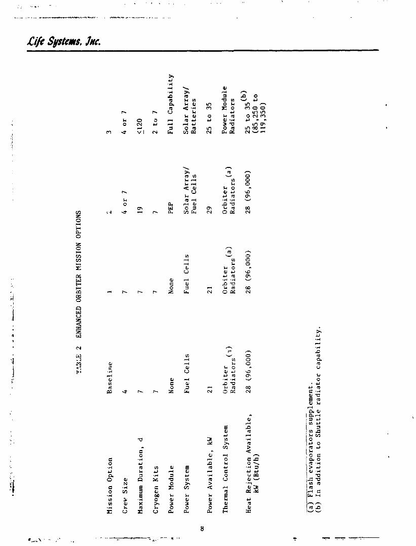
A separate evaluation of ED0 mission options was conducted in parallel to the design evaluations. Three enhanced Shuttle missio~ options were selected and are presented in Table 2. The baseline Shuttle mission characteristics are also given for reference. The primat) difference between the mission opti 111s is the power system which determines the expendables penalty for power usage and the amount of water available on-board the Orbiter.

TABLE 1 EXTENDED DURATION ORBITER DESIGN DATA
C r e w S ize
Mission Duration, d
Metabolic Consump t ion , kg/person-d (lb/person-d)
Oxygen Water, Food/Dr ink Wash Water
Metabolic Production, kgfperson-d (lb/person-d)
Carbon Dioxide Condensate Urine Feces
Orbi ter Leakage, kg/d ( lb/d)
Cabin Air Lock Tunnel Adapter Waste Management
EVA B e g ~ i r e m m t s , ( ~ ) kg/d ( lb ld)
Power Source, kW
Fuel Cells Power Module
(a) Short-term operat ion a t a 10-person l e v e l required. (b) Includes 1.50 kg/d (3.31 lb /d) water and 0.06 kg/d (0.13 lb/d)
so l ids . (c) Assumee 12 h EVA per day (2 persons f o r 6 h). (d) Depending on Power Module configuration.
??X
E
2 EN
HA
NCE
D
OR
BIT
ER
MIS
SIO
N
OPT
ION
S
Mis
sio
n O
pti
on
Cre
w S
ize
Max
imum
Du
rati
on
, d
Cry
og
en K
its
Pow
er M
od
ule
Pow
er
Sy
stem
Pow
er
Av
ail
ab
le,
kW
Th
erm
al
Co
ntr
ol
Sy
stem
Hea
t R
eje
cti
on
Av
ail
ab
le,
kW
(Btu
/h)
Ba
seli
ne
4 7 7 Non
e
Fu
el
Ce
lls
Orb
ite
r R
ad
iato
rs (
3)
(a)
Fla
sh e
va
po
rato
rs
sup
ple
men
t.
(b)
In a
dd
itio
n t
o S
hu
ttle
ra
dia
tor
ca
pa
bil
ity
. 1 I . i
Non
e
Fu
el
Ce
lls
Orb
ite
r R
ad
iato
rs (a
>
,-
L 4
or
7
19
7 PEP
So
lar
Arr
ay
/ F
ue
l C
ell
s
29
Orb
ite
r R
ad
iato
rs (a
1
28 (96,000)
Fu
ll C
ap
ab
ilit
y
So
lar
Arr
ay
/ B
att
eri
es
Pow
er M
od
ule
R
ad
iato
rs
25
to 3
5 (b
)
(85
,25
0 t
o
11
9,3
50
)

For Mission Option One, t h e b a s e l i n e S h u t t l e mission i s simply expanded t o a crew s i z e of seven. Fuel c e l l s a r e s t i l l used f o r power and h e a t r e j e c t i o n i s a t t a i n e d us ing t h e S h u t t l e r a d i a t o r s and f l a s h evaporators . Basel ine miss ion d u r a t i o n i s seven days.
Mission Option Two i s f o r crew s i z e s of f o u r o r seven and uses a PEP t o i n c r e a s e t h e power c a p a b i l i t y of t h e O r b i t e r . The PEP uses a s o l a r a r r a y l f u e l c e l l
t
(SAIFC) power system with t h e f u e l c e l l s operated dur ing darks ide opera t ion and on ly i d l e d dur ing s o l a r c e l l opera t ion . Cryogen expendables f o r power genera t ion a r e g r e a t l y reduced us ing t h e s o l a r a r r a y s . Heat r e j e c t i o n is s t i l l provided by t h e O r b i t e r r a d i a t o r s and f l a s h eva a t o r s . Basel ine mission d u r a t i o n a t t h e 29 kW power l e v e l i s 19 days. P9f
Mission Option Three i s f o r crew s i z e s of f o u r o r seven and uses a 2 u l l capa- b i l i t y power module t o f u r t h e r i n c r e a s e O r b i t e r power c a p a b i l i t y . The power module uses a s o l a r a r r a y l b a t t e r y (SAIBA) power system which completely e l imi - n a t e s expendables f o r on-orbi t power genera t ion . The f u e l c e l l s a r e shutdown and a r e n o t i d l e d on-orb i t a s i s t h e case wi th t h e PEP. Mission dura t ion is l i m i t e d on ly by cryogen b o i l - o f f s i n c e f u e l c e l l s a r e used f o r power genera t ion on descent from o r b i t . P resen t e s t i m a t e s ( t q d i c a t r t h a t wi th improved i n s u l a t i o n , cryogen can be s t o r e d f o r up t o 120 days. The power module a l s o has i t s own h e a t r e j e c t i o n r a d i a t o r s which should e l i m i n a t e t h e need f o r on-orbi t f l a s h evaporator opera t ion .
The EDC and EDCIWVE subsystem designs generated a s p a r t of t h i s s tudy were evaluated f o r a p p l i c a t i o n t o a l l t h r e e miss ions . The VCDS was eva lua ted f o r ED0 with t h e PEP where t h e VCDS water would only be used f o r supplementary hea t r e j e c t i o n and wi th t h e f u l l c a p a b i l i t y power module f o r p o t a b l e water recovery.
Program Organizat ion
The s tudy program was organized i n t o t h r e e t a s k s :
1. C?->on Dioxide Removal Subsystems e v a l u a t i o n f o r EDO.
2 . Water Recovery Subsystems e v a l u a t i o n f o r EDO.
3. Combined CO renoval and water recovery. 2
The fol lowing s e c t i o n s summarize t h e program r e s u l t s and t h e conclus ions and recommendations made.
CARBON DIOXIDE REMOVAL SUBSYSTEMS
The primary func t ion of t h e C02 Removal Subsystem is t o c o n t r o l cab in pCO t o an average p a r t i a l p r e s s u r e of 667 Pa (5.0 mm Hg). The EDC and t h e EDC/& were evaluated f o r S h u t t l e a p p l i c a t i o n . Table 3 shows t h e s p e c i f i c C02 Removal Subsystem design s p e c i f i c a t i o n s used. T t ~ ~ q h u t t l e a i r humidity s p e c i f i c a t i o n s and a c t u a l p r o j e c t e d humidity cond i t ions f o r p o s s i b l e EDC subsystem :ir i n t e r f a c e s a r e presented i n Figures 2 and 3. The f o l l o w i ~ l g s e c t i o n s desc r ibe t h e EDC and EDCIWVE design. The two EDC subsystems a r e then compared t o a l t e r n a t e CO removal concepts f o r t h e t h r e e ED0 miss ion op t ions s e l e c t e d . 2

TABLE 3 C02 REMOVAL SUBSYSTEM DESIGN SPECIFICATIONS
Crew Size
CO2 Removal Rate, kg/h ( lb/h)
Cabin pC02, Pa (mm Hg)
Daily Average Maximum
Cabin p02, W a (psia)
Cabin Temperature, K (F)
Cabin Dew Point, K (F)
Cabin Pressure, kFa (ps ia )
Process A i r Humi3ity Range
Liquid Coolant Temperature, K (F)
See Figures 2 and 3
H2 Supply Plow Rate, kg/h (lb/h)
H2 Relat ive Humidity, I
Purge Cas
Purge Gas Pressure, Wa (ps ia )
E l e c t r i c a l Power, VAC (a) 9 VIX:
Gravity
Koise C r i t e r i a , db
(a) 400 Hz, -7

@? Systems, Ire.


EDC F l i g h t Concept
The EDC Subsystem c o n s i s t s o f an e lec t rochemica l module which yerforms t h e a c t u a l CO removal p rocess , duc t ing and plumbing t o manifold t h e p rocess 2 f l u i d s streams i n t o and o u t of t h e EDC Module (EDCM) and t h e p e r i p h e r a l mechan- i c a l and e l e c t r i c a l components requ i red t o c o n t r o l and monitor subsystem performance. The EDC concept u t i l i z e s t h e f u e l c e l l r e a c t i o n between H and
1
'! ! 0 i n a base e l e c t r o l y t e t o remove CO from an a i r s t ream and ven t i t 06erboard. 2 ~ i e e1ec:rochemical CO removal process t a k e s p l a c e i n a s e r i e s of c e l l s s t acked t o form a modufe. Carbon d iox ide i s removed from a flowing a i r s t ream a s it passes through t h e cathode compartments of t h e EDC c e l l s . The C02 t h a t i s removed from t h e a i r stream i s concentra ted i n t o a H s t ream which i s fed t o t h e anode compartments of t h e c e l l s . The H /CQ2 e f f f l u n t from t h e anode compartments of t h e EDCM i s vented overboard. 2 ~ l e c t r i c ; . l energy, water and waste h e a t a r e byproducts of t h e CO removal process t h e same a s energy, water 2 and waste h e a t a r e produced by f u e l c e l l s .
Subsystem Descr ip t ion
F igure 4 i s t h e S h u t t l e EDC schematic showlllg t h e subsystem components and assemblies . The d e t a i l e d EDC schematic showing subcomponents required t o perform t h e c o n t r o l and monitoring func t ions i s presented i n F igure 5.
Operation. Process a i r i s bypassed from t h e O r b i t e r ARS duc t ing through t h e EDC Subsystem. Process a i r flows through a f i l t e r / i s o l a t i o n va lve , an RH sensor and an a i r l l i q u i d h e a t exchanger p r i o r t o reaching t h e cathode compart- ments of t h e EDCM c e l l s . Procers a i r , dep le ted i n COZ, is re turned t o t h e ARS through a r e l a t i v e humidity (XI) sensor and a f i l t e r / l s o l a t i o n va lve . The RH sensors a r e used t o c o n t r o l EDCM temperature a s a func t ion of process a i r r e l a t i v e humidity cond i t ions . Liquid coo lan t i s used t o remove waste h e a t generated and c o n t r o l EDCM temperature. The l i q u i d coo lan t loop temperature is ad jus ted us ing t h e d i v e r t e r va lve conta ined wi th in t h e Coolant Control Assembly (CCA) which c o n t r o l s t h e amount of coo lan t f lowing through and by- pass ing t h e l i q u i d / l i q u i d h e a t exchanger. An a i r / l i q u i d hea t exchanger i s used upstream of t h e EDCM t o cool t h e process a i r thereby matching t h e process a i r humidity cond i t ions wi th t h e optimum condi t ions f o r EDCM opera t ion . The hea t removed by t h e a i r l l i q u i d h e a t exchanger l e s s e n s t h e requirement f o r h e a t removal by t h e O r b i t e r condensing h e a t exchanger. The l i q u i d / l i q u i d h e a t exchanger i n t e r f a c e s d i r e c t l y with t h e O r b i t e r Water Coolant Loop (WCL) down- stream of t h e cabin temperature c o n t r o l h e a t exchanger.
The H requ i red f o r t h e EDCM i s supp l ied t o t h e EDCM through t h e F l u i d s Control l s s e r d l y (FCA). Flow and p r e s s u r e control/rnonitoring a r e provided by t h e FCA. Shutoff va lves i s o l a t e t h e EDCM from t h e cryogenic Hg supply and t h e H2/C0 overboard ven t . Nitrogen i s used t o purge t h e H -carrying l i n e s of H2 folfow- 2 i n g a shutdown, and of a i r p r i o r t o s t a r t u p (assuming maintenance was performed) A t r i p l e redundant co'nbustible gas sensor i s mounted t o t h e subsystem.
Process c o n t r o l i s provided by t h e Control/Monitor Ins t rumentat ion (C/M I ) . The C/M I i n t e r f a c e s wi th t h e subsystem sensors and a c t u a t o r s , provides auto- matic c o n t r o l of t h e C02 removal p rocess , provides mode t r a n s i t i o n sequences f o r automatic s t a r t u p and shutdown, and monitors sensor l e v e l s t o i n i t i a t e an

Pu
rge
I I
1 control
1 I
a2/co,
out
I I I
EDCM
180.
I Air
Out
1
I
#
I Heat =changer
4 I I I
I
~ontrol/Monitor
AC
Power In -
Instrumentation
Coolant
Control
Assembly
Coolant In
I Coolant Out
loop
I -
Liquid /
L-
-
Loop 1
Liquid
----
$=
- - --
Exchanger
-----
I i -----c
Loop 2
FI
a 4
SHU
'lTLE
ED
C SCHEMATIC

Fluids Control Assembly
Pu
rne B-
Ln
a
Triple Redundant
Gas
Air
Out
Triple Redundant
RH Sensor
Instrumentat ion
Coolant Control Assembly
- -
mt out
-- --
I -
---
---
- Loop 1-
- -
Heat Exchanger
- -
- I
c.Loop 2
Loop
24
-
I -
I
FIG
UR
E 5
SB
UT
nE
EDC
D
ETA
ILED
SC
HEM
ATI
C
I L
1 coou
Coolant In
1
Systems, Jnc.
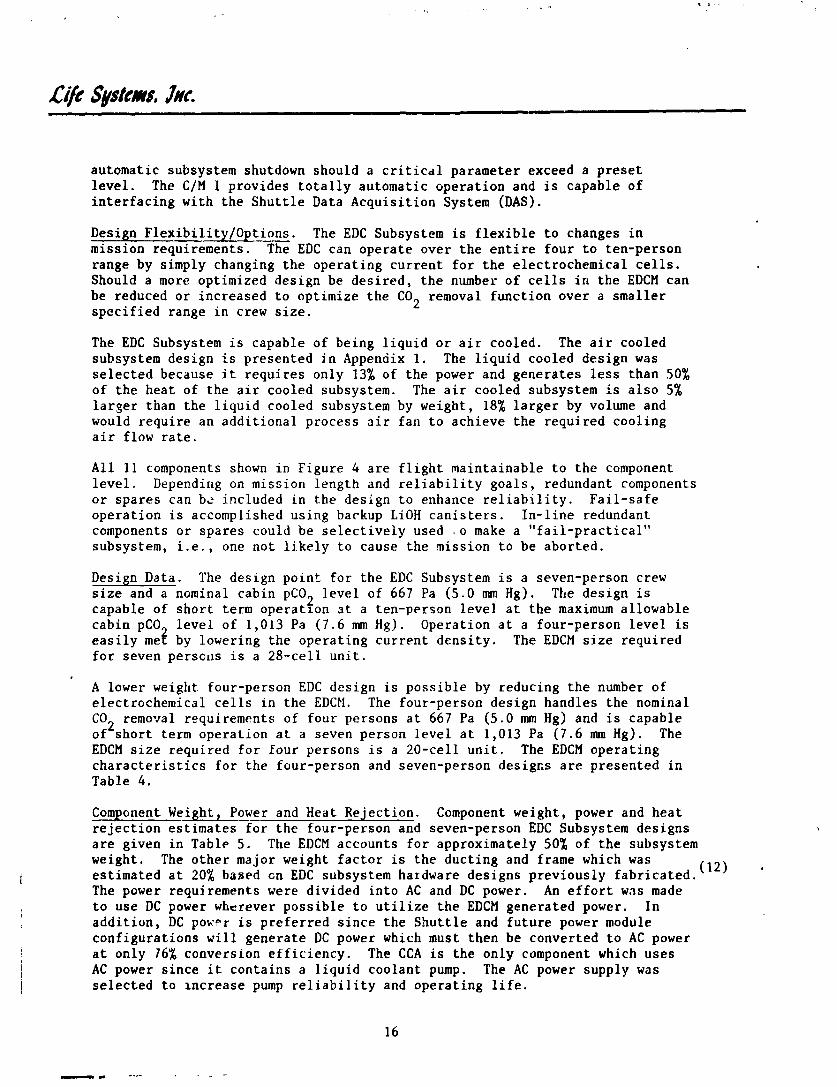
automatic subsystem shutdown should a criticdl parameter exceed a preset level. The C/M I provides totally automatic operation and is capable of interfacing with the Shuttle Data Acquisition System (DAS) . Design Flexibility/Options. The EDC Subsystem is flexible to changes in mission requirements. The EDC can operate over the entire four to ten-person range by simply changing the operating current for the electrochemical cells. Should a more optimized design be desired, the number of cells in the EDCM can be reduced or increased to optimize the CO removal function over a smaller specified range in crew size. 2
The EDC Subsystem is capable of being liquid or air cooled. The air cooled subsystem design is presented in Appenaix 1. The liquid cooled design was selected because it requires only 13% of the power and generates less than 50% of the heat of the air cooled subsystem. The air cooled subsystem is also 5% larger than the liquid cooled subsystem by weight, 18% larger by volume and would require an additional process sir fan to achieve the required cooling air flow rate.
All 11 components shown in Figure 4 are flight maintainable to the component level. Dependirlg on mission length and reliability goals, redundant components or spares can b? included in the design to enhance reliability. Fail-safe operation is accomplished using backup LiOH canisters. In-line redundant components or spares could be selectively used $ 0 make a "fail-practical" subsystem, i.e., one not likely to cause the mission to be aborted.
Design Data. The design point for the EDC Subsystem is a seven-person crew size and a nominal cabin pCO level of 667 Pa (5.0 mm Hg). The design is 2 capable of short term operation at a ten-person level at the maximum allowable cabin pCO level of 1,013 Pa ( 7 . 6 mm Hg). Operation at a four-person level is easily me$ by lowering the operating current density. The EDCM size required for seven persc~is is a 28-cell unit.
A lower weight. four-person EDC design is possible by reducing the number of electrochemical cells in the EDCM. The four-person design handles the nominal CO removal requirements of four persons at 667 Pa (5.0 mm Hg) and is capable 2 of short term operation at a seven person level at 1,013 Pa ( 7 . 6 mm Hg). The EDCM size required for four persons is a 20-cell unit. The EDCM operating characteristics for the four-person and seven-person desigcs are presented in Table 4.
Component Weight, Power and Heat Rejection. Component weight, power and heat rejection estimates3or the four-person and seven-person EDC Subsystem designs are given in Table 5. The EDCM accounts for approximately 50% of the subsystem weight. The other major weight factor is the ducting and frame which was estimated at 20% based cn EDC subsystem hardware designs previously fabricated. (12)
The power requirements were divided into AC and DC power. An effort was made to use DC power wherever possible to utilize the EDCM generated power. In addition, DC power is preferred since the Shuttle and future power module configurations will generate DC power which must then be converted to AC power at only 76% conversion efficiency. The CCA is the only component which uses AC power since it contains a liquid coolant pump. The AC power supply was selected to increase pump reliability and operating life.

TABLE 4 SHUTTLE EDCM OPERATING CHARACTERISTICS
Crew Size
Number of Cells
Current (Nominal), A
Cell Voltage (Nominal), V
Power Generated, W
Waste Heat Produced, W
C02 Removed, kg/d (lb/d)
O2 Consumed, kg/d (lb/d)
H2 Consumed, kg/d (lb/d)
H20 Generdted, kg/d (lb/d)

TABL
E 5
EDC
SUBSYSTEM COMPONENT WEIGHT,
POWER AND
HEAT GENERATION S-Y
pa
t Weinht .
Power. W
Heat
Component
EDCH
Fluids Control Assembly
Coolant Control Assembly
Heat Exchanger (Liq/Liq)
Heat Exchanger (Air/Liq)
Filter/Isolation Valve
RH Sensor
Combustible Gas Se
nsor
Instrumentation
Ducting/Frame (20%)
Total
Packaging
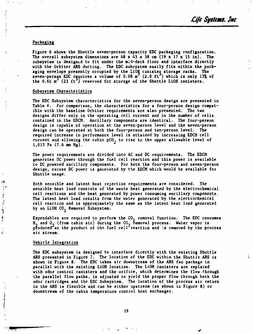
i Figure 6 shows the Shu t t l e seven-person capaci ty EDC packaging configurat iou. The ove ra l l subsystem dimensions a r e 48 x 43 x 38 cm (19 x 17 x 15 i n ) . The aubsystern is designtd t o f i t under t h e mid-deck f l o o r and i n t e r f a c e d i r e c t l y with t he Orbi te r ARS ducting. The EDC subuystem e a s i l y f i t s within t h e pack- aging envelope presen t ly occupied by the L i O g can is te f s to rage racks. The
, seven-persgn EDC r fqui res a volume of 0.08 m (2.8 f t ) which is only 13% of t h e 0.65 m (23 f t ) reserved f o r s to rage of t he Shu t t l e LiOH can i s t e r s .
Subsystem Charac t e r i s t i c s
The EDC Subsystem c h a r a c t e r i s t i c s f o r the seven-person design a r e presented i n Table 6 . For comparison, t he c h a r a c t e r i s t i c s f o r a four-person design compat- i b l e with t h e base l ine Orbi te r requirements a r e a l s o presented. The two designs d i f f e r only i n the operat ing c e l l cu r r en t and i n t he number of c e l l s contained i n t he EDCM. Anci l lary components a r e i d e n t i c a l . The four-person design is capable of operat ion a t t he seven-person l eve l and the seven-person design can be operated a t both t he four-person and ten-person l eve l . The required increase i n performance l eve l is a t t a ined by increasing EDCM c e l l cur ren t and allowing the cabin pCOZ t o r i s e t o the upper allowable l eve l of 1,013 Pa (7.6 mm Hg).
The power requirements a r e divided i n t o AC and DC requirements. The EDCM generates DC power through the f u e l c e l l reac t ion and t h i s power is ava i l ab l e t o DC powered a n c i l l a r y components. For both t he four-parson and seven-person design, excess DC power i s generated by the EDCM which would be ava i l ab l e f o r Shu t t l e usage.
Both s ens ib l e and Latent heat r e j ec t i on requirements a r e considered. The sens ib le hea t load cons i s t s of t he waste hea t generated by the electrochemical c e l l reac t ions and the heat generated by power consuming a n c i l l a r y coaponents. The l a t e n t heat load r e s u l t s from the water generated by t h e electrochemical c e l l reac t ion and i s approximately t h e same a s t he l a t e n t heat load generated by an LiOH C02 Removal Subsystem.
Expendables a r e required t o perform the C02 removal funct ion. The EDC consumes H and O2 (from cabin a i r ) during the C02 removal process. Water vapor is p$oduced a s the product of the fue l c e l l r e a c t i m and <s removed by t h e process a i r stream.
Vehicle In tegra t ion
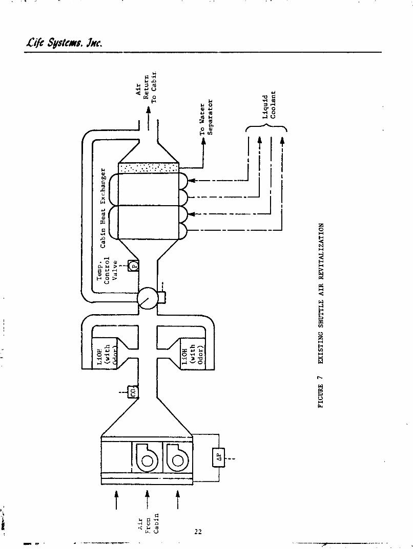
The EDC subsystem i s designed t o i n t e r f a c e d i r e c t l y with t he e x i s t i n g Shu t t l e ARS presented i n Figure 7. The loca t ion of t he EDC wi th in t he Shu t t l e ARS i s shown i n Figure 8 . The EDC takes a i r downstream of t.he ARS fan package i n p a r a l l e l with t he ex i s t i ng LiOH loca t ion . The LiOH c a n i s t e r s a r e replaced with odor cont ro l can i s t e r s and t h e o r i f i c e , which determines t he flow through the p a r a l l e l flow pa ths , is adjusted t o y i e ld the proper flow through both t he odor ca r t r i dges and thc EDC Subsystem. The loca t ion of t he process a i r r e tu rn t o t he ARS is f l e x i b l e and can be e i t h e r upstream (as shown i n Figure 8 ) o r do-mstream of t he cabin temperature control heat exchanger.

Liquid /Liquid
Heat Exchanger
CC
A
FCA
Process Air Duct
Filter/Isolation
Vaiv
e
43 cm (
7 in) v
FIGURE 6
SH
l-E
DC CONFIGUaATION
(%lV
EH
PPER
SON)
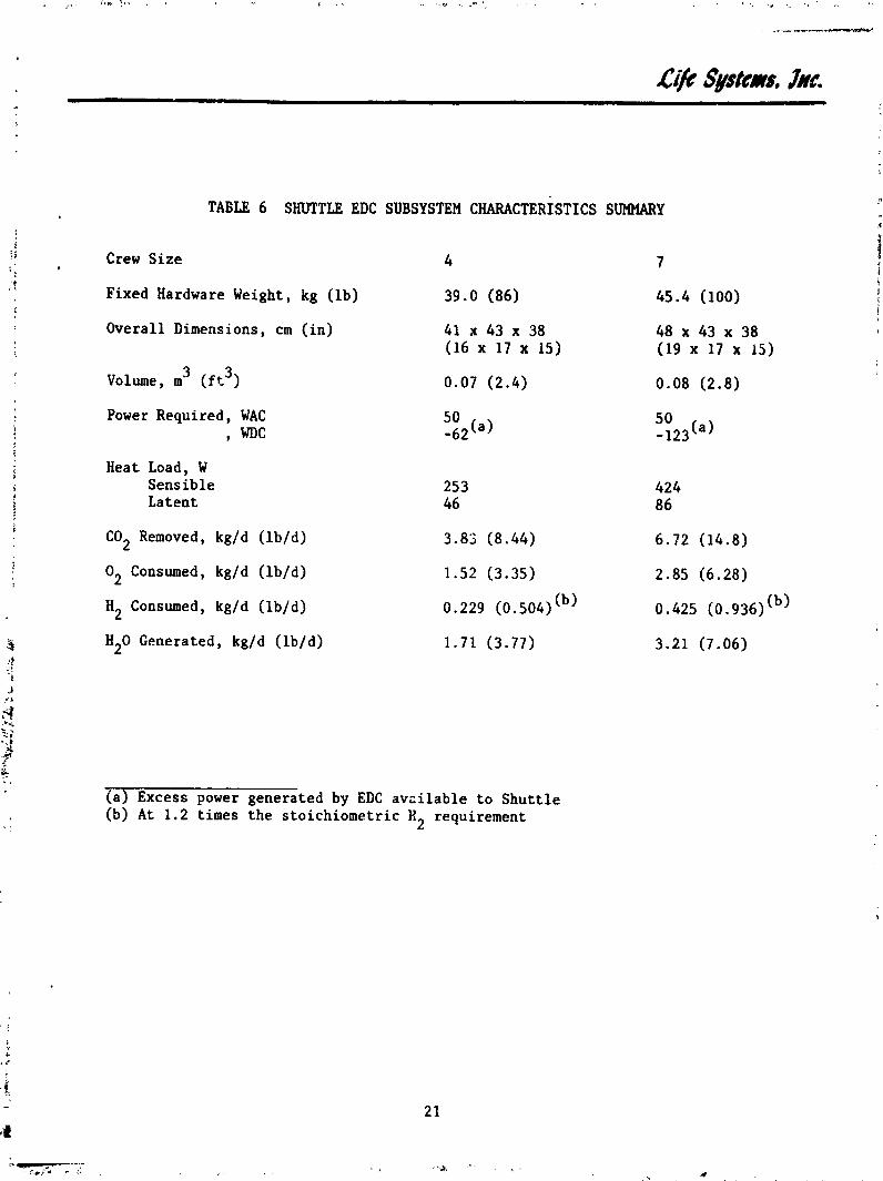
TABLE 6 SHUTTLE EDC SUBSYSTEM CHARACTERISTICS SUMMARY
Crew Size 4 7
Fixed Hardware Weight, kg (lb) 39 .O (86) 45.4 (100)
Overall Dimensions, cm (in) 41 x 43 x 38 48 x 43 x 38 (16 x 17 x 15) (19 x 17 x 15)
3 3 Volume, m (ft ) 0.07 (2.4) 0.08 (2.8)
Power Required, WAC , WDC
Heat Load, W Sensible La tent
C02 Removed, kg/d (lb/d)
O2 Consumed, kg/d (lb/d) 1.52 (3.35) 2.85 (6.28)
H2 Consumed, kg/d (lb/d)
H20 Generated, kg/d (lb/d) 1.71 (3.77) 3.21 (7.06)
(a) Excess power generated by EDC avcilable to Shuttle (b) At 1.2 times the stoichiometric X2 requirement
t t t L C -


The EDC r e q u i r e s f i v e S h u t t l e mechanical i n t e r f a c e s : a i r , l i q u i d cc.01 a n t , N2 ' cryogenic H and overboard v e n t . A l l r equ i red resources p r e s e n t l y e x i s t on 2 t h e S h u t t l e .
Development S t a t u s
The EDC subsystem technology is w e l l e s t a b l i s h e d . Two prepro to type un i been f a b r i c a t e d and d e l i v e r e d t o NASA: t h e s ix-person SSP EDC t 8 have and t h e three-person RLSE EDC Subsystem ( r e f e r r e d t o a s t h e CS-3). fY4f Y"e~hoto- graph of t h e CS-3 is p resen ted i n F igure 9. The EDC Subsystem can be a v a i l a b l e f o r f l i g h t a p p l i c a t i o n by 1983.
EDCIWVE F l i g h t Concept
The EDC/WVE Subsystem c o n s i s t s of an EDCM which performs t h e C02 removal p rocess , a WVE Module (WVEM) which genera tes t h e 0 and H consumed by t h e EDC f o r t h e C02 removal p rocess , duc t ing and plumbing 80 manitold t h e p rocess gases i n t o and o u t of t h e e lec t rochemica l modules and t h e p e r i p h e r a l mechanical :nd e l e c t r i c a l components r equ i red t o c o n t r o l and monitor subsystem performance. The EDC concept i s a s desc r ibed p rev ious ly . The WVE concept e l e c t r o l y z e s water vapor conta ined i n t h e a i r s t ream t o genera te H f o r use i n t h e EDC and 0 which is generated d i r e c t l y i n t o t h e a i r s t ream. $he e l e c t r o l y s i s p rocess 2 t akes p l a c e i n a s e r i e s of e l ec t rochemica l c e l l s s t acked t o form a module. Water vapor is removed from a f lowing a i r s t ream a s it passes through t h e anode compartments of t h e WW c e l l s . The 0 generated a t t h e anode i s removed wi th t h e process a i r . The H2 generated a t $he cathode i s manifolded from t h e WVEM t o t h e EDCM. The WVEM genera tes 1 .2 t imes t h e 0 and H consumed, and 2 consmes 1.2 t imes t h e water genera ted i n t h e EDC process . The 20% a d d i t i o n a l H which i s no t consumed by t h e EDCM i s vented overboard wi th t h e C02. The 2 excess 0 genera ted reduces O r b i t e r metabol ic 0 requirements . The a d d i t i o n a l 2 water consumed reduces t h e l a t e n t h e a t removal toad on t h e condensing hea t
exchanger. The e l e c t r o l y s i s process r e q u i r e s e l e c t r i c a l en r rgy and waste h e a t is genera ted a s a byproduct.
Subsystem Descr ip t ion
F igure 10 is t h e S h u t t l e EDC/hW schematic shovlng t h e subsystem components and assembl ies . The d e t a i l e d EDC/WVE schematic showing t h e subcomponents required t o perform t h e c o n t r o l and monitoring func t ions i s p resec ted i n F igure 11.
Operation. Process a i r i s bypassed from t h e ARS duc t ing t o t h e EDCIWVE subsystem Process a i r flows through a f i l t e r / i s o l a t i o n v a l v e , an RH sensor and an a i r l i q u i d hea t exchanger p r i o r t o reaching t h e EDCM and t h e W M . Process a i r flows through both modules i n p a r a l l e l . Separa te RH s e n s o r s a r e used on t h e o u t l e t a i r s tream from each module. The a i r is then recombined and exhausts t h e subsystem through a second f i l t e r / i s o l a t i o n va lve . The RH sensors a r e used t o c o n t r o l EDCM and WVEM temperature a s a func t ion of p rocess a i r RH cond i t ions . Liquid coo lan t is used t o remove waste hea t genera ted and t o c o n t r o l module temperatures . The l i q u i d coo lan t loop temperature is a d j u s t e d us ing a d i v e r t e r valve conta ined wi th in t h e CCA which c o n t r o l s t h e amount of coo lan t f lowing through and bypassing t h e l i q u i d / l i q u i d hea t exchanger. An a i r / l i q u i d hea t exchanger is used upstream of t h e e lec t rochemica l modules t o


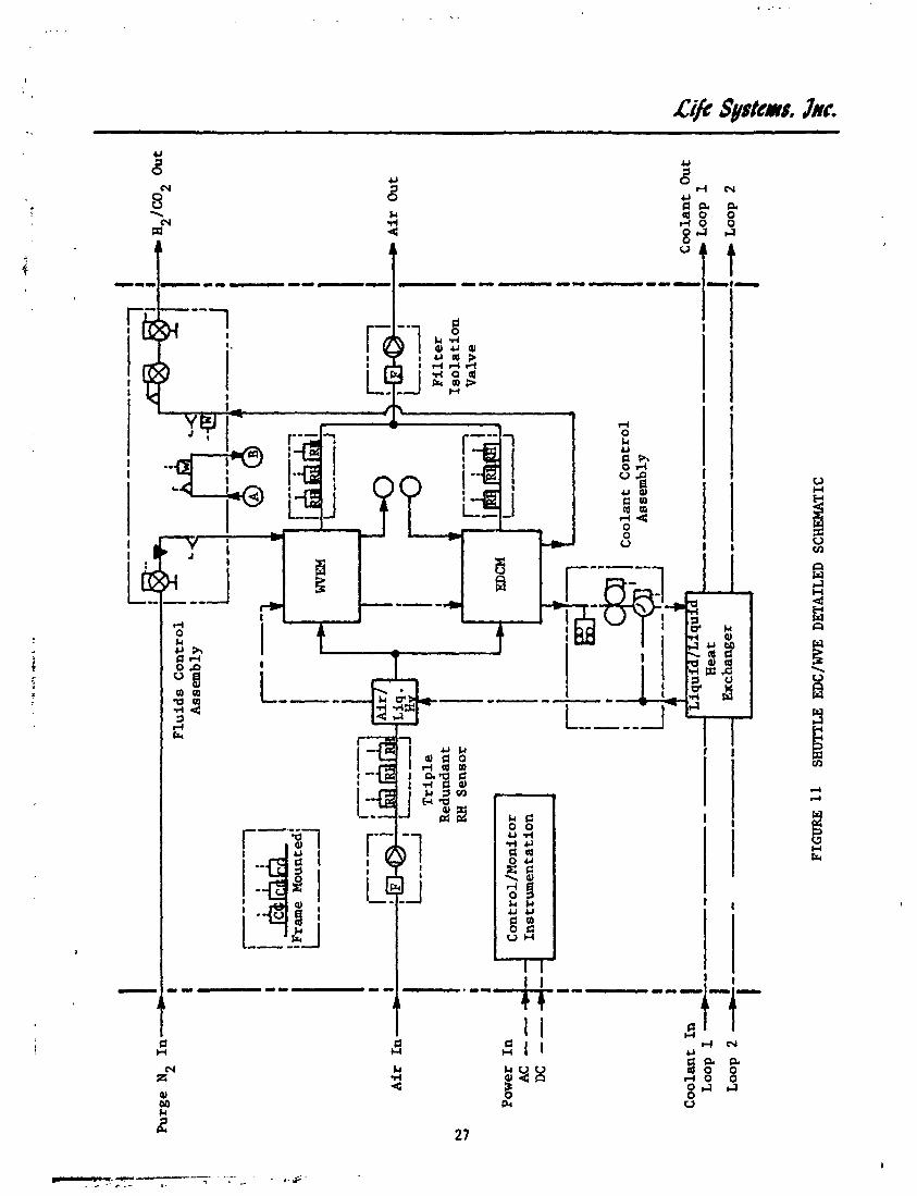

cool the process air thereby matching the process air humidity conditions with optimum conditions for EDCM and WVEM operation. The liquid/liquid heat ex- changer interfaces directly with the Orbiter WCL downstream of tt2 shuttle cabin temperature control heat exchanger. Again, the Orbiter's condensing heat exchanger load is lessened by the amount of hcat removed by the air/ liquid heat exchanger upstream of the modules.
The H2 generated in the WVEM is used directly by the EDCM. Pressure and flow measurements between the two modules are provided by the FCA. The 3CA also interfaces with the N purge source and the overboard H /C02 vent. The FCA 2 2 provides all H flow path control and monitoring functions mcluding N purge. A triple redungant combustible gas sensor is located on the subsystem trame.
Process control is provided by the C/H I. The C/M I interfaces with the subsystem sensors and actuators, provides automatic control of the water electrolysis and C02 removal processes, provides mode transition sequences for automatic startup and shutdown, and monitors sensor levels to initiate an automatic subsystem shutdown should a critical parameter exceed a preset level. The C/M I provides totally automatic operation and is capable of interfacing with the Shuttle DAS.
Design Flexibility/Optiol.s. The EDC/WVE S~bsystem is flexible to changes in mission requirements. ~ h s EDC/WVE can operate over the entire four to ten-person range by simply changing the operating current for the electrochemical cells. Should a more optimized design be desired, the number of electrochemical cells in the EDCM and WVEM can be reduced or increased to provide the CO removal 2 function over a smaller specified range in x e w size. The EDCIWVE subsystem is capable of being either liquid cooled or air cooled. The air-cooled subsystem design is presented in Appendix 2. The liquid-cooled design was selected because it requires only 50% of the power and generates less than 50% of the heat of the air cooled subsystem. The air-cooled subsystem is also 7% larger than the liquid cooled system by weight, 17% larger by volume and would require an additional process air fan to achieve the required cooling air flow rate.
All 13 components shown in Figure 10 are flight maintainable to the component level. Depending on mission length and reliability goals, redundant components or spares can be included in the design to enhance reliability. Fail-safe operation is accomplished using backup LiOH canisters. In-line redundant componmts or spares could be selectively used to make a "fail-practical" subsystem.
Design/Data. The design point for the EDCIWVE Subsystem is a seven-person crew size and a nominal cabin pCO level of 667 Pa (5.0 mm Hg). The design is capable of short-term operation at a ten-pdrson level at the maximum allowable pCOZ level of 1,013 Pa (7.4 m Hg). Operation at a four-person level is easily met by lowering the operating current for the electrochemical modules. The EDCM size required to perform thj n function is a 28-cell unit. The WVEM size required is a 24-cell unit.
A lower weight four-~erson EDC/WVF: design is possible by reducing the number of electrochemical cells in the EDCM and WVEM. The four-person design handles the nominal CO removal requirements for four-persons at 667 Pa (5.0 uun Hg) 2 and is capable of short-term operation at the seven-person level at 1,013 Pa
. , .-....... .,..... .... " -,I .. I... RIL. .lj '
-

1
(7.6 mm Hg). The EDCM s i z e required f o r four persons i s a 20-cel l un i t . The four person W'EM contains 17 c e l l s . The EDCM and WVEM operat ing charac te r i s -
! i i
t i c s a r e presented i n Table 7. 4 i
Component Weight, Power and H-at Rejection. Component weight, power and hea t r e j ec t ion est imates f o r t he four-person and sevencperson EDCIWVE Subsystem designs a r e glven i n Table 8. he EDCM and WVEM account f o r approximately 50% of the subsystem weight. The other major weight f a c t o r i s t h e duct ing and the frame weight w h i c t y q s estimated a t 25% based on previous EDCIWVE Subsystem hardware designs. The power requirements were divided i n t o AC and DC power. An e f f o r t was made t o use lower penal ty DC power wherever poss ib le . The EDCM generated power is used by the WVEM t.o reduce i t s power req~lirements. The only component requi r ing AC power i s t h e CCA.
Packaging
The packaging concept f o r t he seven-person capaci ty EDC/WVE Subsystem is presented i n Figure 12. The ove ra l l subsystem dimensions a r e 81 x 43 x 38 cm (32 x 17 x 15 i n ) . The subsystem i s designed t o f i t under the mid-deck f l o o r and in t e r f ace d i r e c t l y with the Orbi te r ARS ducting. The EDCIWVE Subsystem e a s i l y f i t s within the packaging envelope present ly occupied by She LiOH c a n i s t e r s torage racks. The EDCIWVE requi res a volume of 0.13 ;a (4.7 f t ) which i s only 20% of t he volume present ly reserved f o r L i O H can i s t e r s torage.
Subsystem Charac ter i s t ics
The subsystem c h a r a c t e r i s t i c s f o r the four-person and the seven-person EDC/WVE designs a r e presented i n Table 9 . Again, t he two designs d i f f e r only i n t he operat ing c e l l cur ren ts and i n the number of EDCM and WVEM c e l l s . Anci l lary components a r e i d e n t i c a l . The four-person design i s capable of operat ion a t t he seven-person l eve l . The seven-person design can be operated a t both t h e four-person and ten-person l eve l . The increase i n performance i s a t t a ined by increasing EDCM and WVEM c e l l cur ren ts and allowing the cabin pC02 t o r i s e t o the upper allowable l e v e l of 1,013 Pa (7.6 mm Hg).
The power requirements axe divided i n t o AC and DC requirements and include t h e power required f o r a n c i l l a r y components, the power required by the WVEM and the power generated by the EDCM. The EDCM generated power i s used d i r e c t 1 the WVEM t o o f f s e t a por t ion of the water e l e c t r o l y s i s power requirements. Y ~ Y
Both sens ib le an3 l a t e n t hea t r e j ec t ion requirements a r e considered. The sens ib l e heat load includes t h a t due t o the power required f o r the a n c i l l a r y components and waste hea t generated i n t he electrochemical c e l l reac t ions . The ne t water removal from the cabin a i r oy the EDCIWVE process r e s u l t s i n the negative l a t e n t heat load.
The EDC/WVE does not require any expendables except those used by the f u e l c e l l s t o generate power f o r the subsystem. The use of the WVEM t o generate t he EDC consumables el iminates t he need f o r using Shu t t l e 0 and H2 expendables. Since the WVEM generates 20.6 more O2 than i s used by the EDZM, t he EDCIWVE a c t u a l l y has a negative consumables f a c t o r f o r comparison purposes s ince 0 is added t o the cabin a i r f o r metabolic consumption. 2

TABLE 7 SHUTTLE EDCIWVE MODULE OPERATING CHARACTERISTICS
Crew Size
Number of Cel l s
Current, A
Cel l Voltage (Nominal), V
Power Consumed, W
Waste Heat Produced, W
C02 Removed, kg/d ( lb /d)
O2 Consumed, kg/d ( lb ld )
H2 Consumed, kg/d ( lb/d)
H20 Generated, kg/d ( lb ld)
EDCM
4
2 0
10.6
0.48
- 102
163
6.72 (8 .44)
1.52 (3 .35)
0 .19 (0 .42)
1.71 (3 .77)
EDCM - 7

TABLE
8 EDCIWVE S
UBSYSTEM COMPONENT WEIGHT, POWER AND HEAT GENERATION SUMMARY
Comp
onen
t
EDCM
WVEM
Fluids Control As
semb
ly
Coolant Control As
semb
ly
W
Heat Exchanger (L
iq/L
iq)
C
Heat E
xchanger (A
ir/L
iq)
Filter/Isolation Valve
RH Sensor
Combustible Gas Sensor
Instrumentation
Ducting/Frame (
35%
) Total
No.
Req'
d
1 1
1 1 1 1 2 3 1 1 - -
13
4-Person
Weight.
Powe
r. W
Heat
Gen. ,
W
163
105 10
50
- -
- -
- -
15 5 2 0 -- -
368
.
- - - -
- - -
Weight,
Power, W
Heat
AC
DC
Gen. ,
W
334
214
10
5 0
- -
- -
- -
15
5 20
- -
-- 648


Crew S i z e
TABLE 9 SHUTTLE EDCIWVE SUBSYSTEM CHARACTERISTICS SLJMMARY
F i x e d Hardware Weighi , kg ( l b )
O v e r a l l Dimens ions , cm ( i n )
3 ' Volume, m ( f t " )
Power Required, WAC , WC
Heat Load, W S e n s i b l e Latent
C02 Removed, kg/d ( l b / d )
O2 Consumed, kg/d ( i b / d )
H 2 Consumed, kg/d ( l b / d )
H20 Generated, kg/d ( l b / d )
Li/c Systems, Jnc.
Vehicle Integration
The EDCIWVE Subsystem is designed to interface directly with the existing Shuttle ARS. The location of the EDC/WVE within the Shuttle ARS schematic i~ shown in Figure 13. The EDC/W\'E takes air downstream of the ARS fan package and in parallel with the existing LiOH location. The LiOH canisters are replaced with odor control canisters and the orifice which determines the flow through the parallel flow paths is adjusted to yield the proper flows thrmgh both the odor cartridges and the EDCIWIE Subsystem. Process air can be re,- turned to the ARS either upstream (as shown in Figure 13) or downstream of the cabin temperature control heat exchanges.
The EDCIWVE Subsystem requires four mechanical Shuttle interfaces: air, liquid coolant, N and overboard vent. All resources exist and are presently used 2 within the Shuttle EC/LSS.
Development Status - - The EDC/WVE zubsystem technology is well established. A three-person EDC/k'VE, designed to provide tot etabolic 0 and CO control, w?s built for NASA under the RLSE program. ?h'P A photograph 2 of the prepmtotype EDC/WVE is shown in Figure 14. The EDCIWVE Subsystem can be available for flight application by 1983.
CO Removal Sut :ystems Comparison 2
The EDC and EDC/WVE subsystems were compared to LiOH and (117 solid amine CO Removal Subsystems: HS-C/RH Control and HS-C/Water Save. The enhc nced
2
Orbiter mission options used in comparing thc five 00 Remmal Subsystems were presented in Table 2. 2
For enhanced Orbiter Mission Options One and Two, sufficient potable water exists so that watr- removed by a CO Removal Subsystem and vented overboard is not considered an expendable penafty. Mission Option Three, however, does not generate any potable water since fuel cells are not used. Any water vented overboard by the CO Removal Subsystem must be considered an expendable
2 for the mission since it would have to be replaced by water recovery or addi- tional water storage.
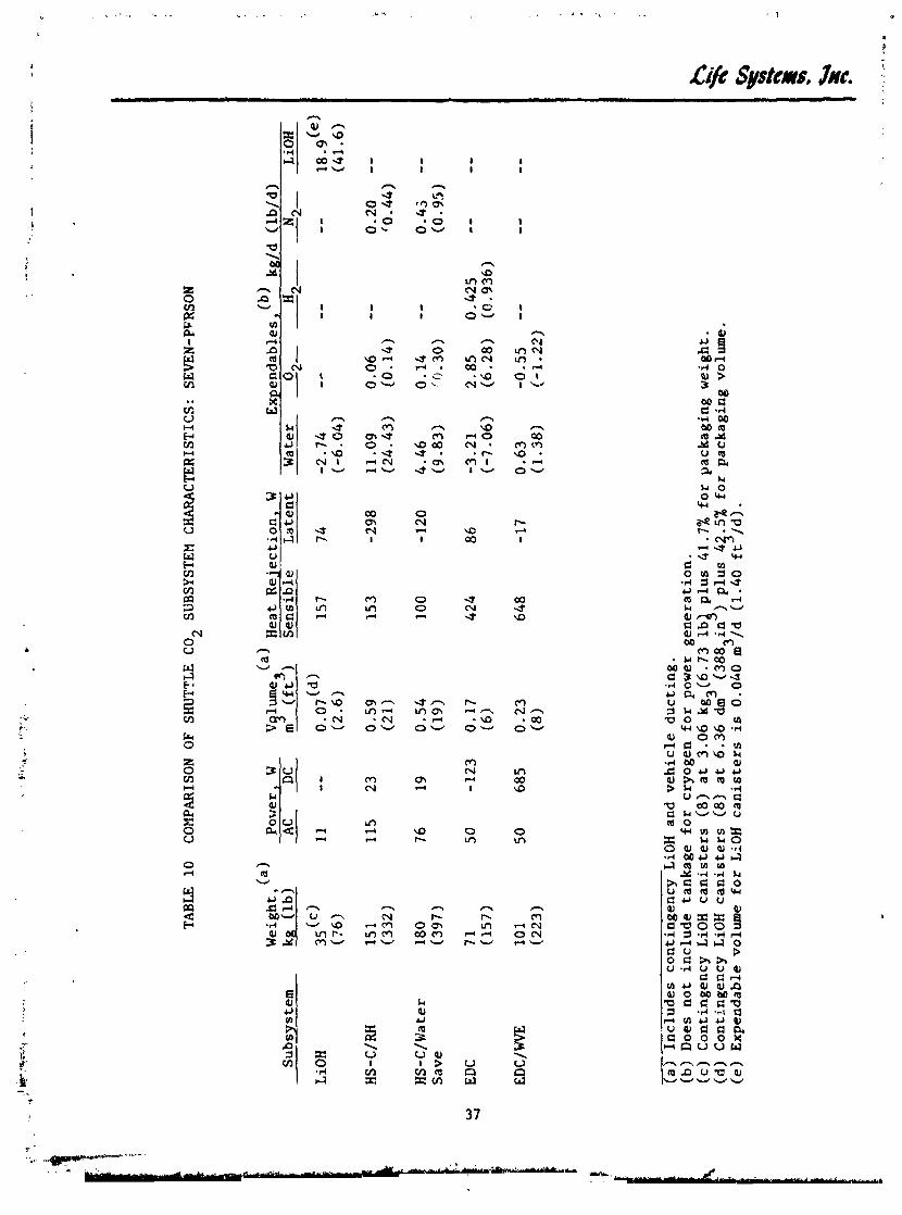
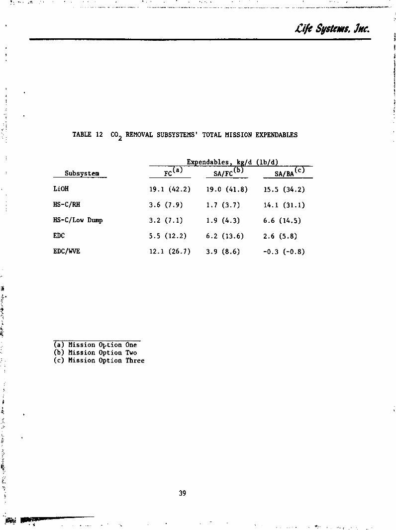
Table 10 summarizes the C02 Removal Subsystems' characteristics for comparison. The weight and volume estimates iriclude contingency LiOH canisters and vehicle ducting. Table 11 summarizes the subsystem power consumption expendables for Mission Options One and Two. The total mission expendables required are prese~ted in Table 12 for each of the three mission options as characterizcd by the power system configuratio.~. Expendables include process corlsumables and cryogen for power generation. A tankage penalty of 100% wzs assumed for 02, H2 and N . Expendables for Mirsion Option TSree also in e water vented averbcrrd wifh a tankage pe-ialty of 22.4% of the water loss. cJs9

\
Temp.
Cab
in Heat
Exc
han
ger
Odor
. .
. *. .* . . .
.* . . . . 0. . . ><l I_C
- Air
Fro
m ----t
Cab
in _
_C
Pu
rge N2
r L
H~
O
to
Ove
rboa
rd 3
ent
W
VI
I T
o S
epar
ator
Water
I
C02
Rem
oval
Subsystem
Hea
t E
xche
ngl !
r
FIG
UR
E
13
SHU
TTLE
EDCfWVE L
OC
AT
ION
Air
R
etu
rn
To
Cab
in
Liq
uid
C
oola
nt

TABLE
10
COMPARISON OF SHUTTLE CO,
SUBSYSTEM CHARACTERISTICS: S
EVEN
-PFR
SON
Weight,(a)
Power, W
Subs~s
tern
kg
(lb)
AC
DC
--
HS-Water
180
76
19
Save
(397
W
EDC
4
7 1
50
-123
(157)
EDC
/ WVE
1
01
50
685
(223)
V lume
Heat Rejection, W
mg (ft3)
Sensible
latent
0.07(~)
157
7 4
(2.6
)
0.59
15
3
-298
(21)
0.54
100
- 120
(1
9
0.17
424
8 6
(6)
0.2
3
648
- 17
(8
expendable^,'^' k
g/d
(lb/d)
0
H
Water
2-
- 2-
-2- N
---
LiOH
-
(a) Includes contingency LiOH and vehicle ducting.
(b) Does not include tankage for cryogen for power generation.
(c) Contingency LiOH canisters (8) at
3.0
6
kg
3(6
.73
lb4 plus
41
.7%
for packaging weight.
(d) Contingency LiOH canisters (8)
at 6.36 dm
(3883in
) plus
45
.5%
for packaging volume.
(e) Expendable volume for LiOH canisters is
O.O
hO m
/d
(1.4
0 ft /
d).

Subsys tern
LiOH
HS-C/RH
HS-C/Water Save
EDC
EDC/ WVE
TABLE 11 EXPENDABLES FOR POWER CONSUMED: SEWN-PERSONS
Power, (a) w AC DC -- 11 --
115 23
7 6 19
5 0 -123
50 685
Baselinyb9rbiter Expen- Orbiter w ' tb PEP Expen- dables, kg/d ( W d ) dables,'~~ kg/d (lb/d)
0 - H 2- - 0 2- - 2- H - 2-
(a) Power conversion efficiency of 76% for AC power. (b) Fuel cell 0 and H2 consumption at 7.84 kg/kW-d (17.26 lb/kW-d) and
0.99 kg/k~-? (2.17 lb/kW-d) , respectively. (c) Fuel cell 0 and H2 consumption at 2.96 kg/kW-d (6.52 lb/kW-d) and
0.37 kg/kw-$ (0.82 lb/kW-d) , respectively. (d) Assumes EDC power generated is used on-board the Shuttle.
Subsys tern
LiOH
HS-C/RH
HS-C/I,ow Dump
EDC
EDCIWVE
(a) Mission Option One (b) Mission Option Two (c) Mission Option Three
Expendables, kg/d (lb/d)
F C ( ~ ) S A / F C ( ~ ) SA/BA(')
TABLE 12 C02 REMOVAL SUBSYSTEMS' TOTAL MISSION EXPENDABLES
Mission Option One
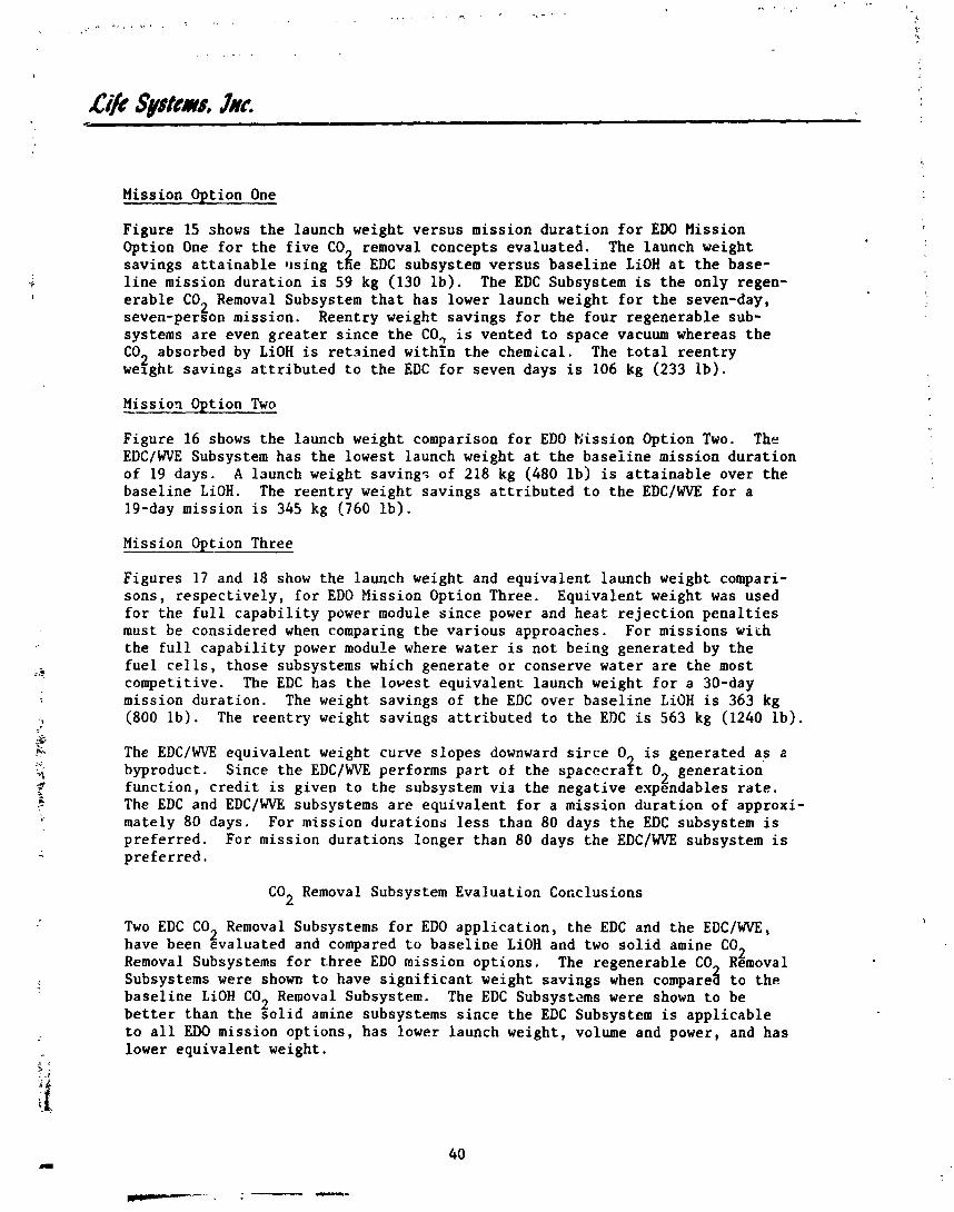
Figure 15 shows the launch weight versus mission duration for ED0 Mission Option One for the five CO removal concepts evaluated. The launch weight savings attainable using tie EDC subsystem versus baseline LiOH at the base- line mission duration is 59 kg (130 lb). The EDC Subsystem is the only regen- erable CO Removal Subsystem that has lower launch weight for the seven-day, 2 seven-person mission. Reentry weight savings for the four regenerable sub- systems are even greater since the CO, is vented to space vacuum whereas the CO absorbed by LiOH is retained within the chemical. The total reentry 2 weight savings attributed to the EDC for seven days is 106 kg (233 lb).
Missio9 Option Two
Figure 16 shows the launch weight comparison for ED0 Eission Option Two. The EDCIWVE Subsystem has the lowest launch weight at the baseiine mission duration of 19 days. A launch weight saving? of 218 kg (480 lb) is attainable over the baseline LiOH. The reentry weight savings attributed to the EDC/WVE for a 19-day mission is 345 kg (760 lb).
Mission Option Three
Figures 17 and 18 show the launch weight and equivalent launch weight compari- sons, respectively, for ED0 Mission Option Three. Equivalent weight was used for the full capability power module since power and heat rejection penalties must be considered when comparing the various approaches. For missions wirh the full capability power module where water is not being generated by the fuel cells, those subsystems which generate or conserve water are the most competitive. The EDC has the lowest equivalent launch weight for a 30-day mission duration. The weight savings of the EDC over baseline LiOH is 363 kg (800 lb). The reentry weight savings attributed to the EDC is 563 kg (1240 lb).
The EDC/WVE equivalent weight curve slopes downward sirce 0 is generated as a byproduct. Since the EDC/WVE performs part of the spacccra$t O2 generation function, credit is given to the subsystem via the negative expendables rate. The EDC and EDC/WVE subsystems are equivalent for a mission duration of approxi- mately 80 days. For mission durations less than 80 days the EDC subsystem is preferred. For mission durations longer than 80 days the EDC/WVE subsystem is preferred.
CO Removal Subsystem Evaluation Coficlusions 2
Two EDC CO Removal Subsystems for ED0 application, the EDC and the EDC/WVE, 2 have been evaluated and compared to baseline LiOH and two solid amine CO 2 Removal Subsys tems for t.hree ED0 mission options. The regenerable CO Removal
Subsystems were shown to have significant weight savings when compare$ to the baseline LiOH CO Removal Subsystem. The EDC Subsystems were shown to be 2 better than the solid amine subsystems since the EDC Subsystem is applicable to all ED0 mission options, has lower launch weight, volume and power, and has lower equivalent weight.

U r s i o n Duration, d
n m 15 co2 BEMDVAL SUBSYSTEMS LAUNCH WEIGHT COMPARISON: MISSIOR OHION
41

FIGURE 16 C02 REMOVAL SUBSYSTEMS LAUIVCEI WEIGHT COMPARIGON: MISS1010 OP
5 10 15 20 2 5 30 Mieaion Duration, d
TION TWO

17 CO2 =OVAL SUBSYSTEMS ~AUNCH WZIWT COMPARISON: MISSION OPTION THREE

Mirsioa Duration, d
FIGURE 18 Cot REMOVAL SUBSYSTEM EQUIVALENT WEIGHT COMPARISON: MISSXON OPTION TRUE

Based on t h e s e r e s u l t s , t h e fo l lowing conclus ions were reached:
1. The LiOH CO Removal Subsvstem should be r ~ p l a c e d by a r egenerab le C 0 2 ~ e m o v a b t e Subsys tern f o r ED0 a p p l i c a t i o n .
2 . Both t h e EDC and EDC/WVE a r e a p p l i c a b l e t o ED0 C02 removal.
3 . An EDC subsystem is p r e f a ~ ~ r e d over a s o l i d amine C02 Removal Sub- system f o r t h e miss ions eva lua ted .
WATER RECOVERY SUBSYSTEM
The f u n c t i o n of a Water Recovery Subsystem (WRS) i s t o rec la im water from u r i n e , wash water and condensate. The recovered water can be used by t h e S h u t t l e f l a s h evapora to r s f o r supplemental h e a t r e j e c t i o n o r , wi th a d d i t i o n a l t r ea tment , used t o meet p o t a b l e wa te r requirements . The VCDS was eva lua ted f o r S h u t t l e water recovery a p p l i c a t i o n . Table 13 shows t h e s p e c i f i c VCDS des ign s p e c i f i c a t i o n s used. The fo l lowing s e c t i a n s d e s c r i b e t h e VCDS d e s i g n e v a l u a t i o n and comparison t o on-board wa te r s t o r a g e .
VCDS F l i g h t Concept
The VCDS c o n s i s t s of t h e s t i l l which performs t h e d i s t i l l a t i o n r r o c e s s , t h e r e c y c l e t ank which f i l t e r s and s t o r e s t h e concen t ra ted b r i n e , plumbing t o and from t h e subsystem components, and t h e p e r i p h e r a l mechanical and e l e c t r i c a l components r equ i red t o cont.ro1 and monitor subsystem performance. The p r i n c i - p l e of o p e r a t i o n w i t h i n t h e s t i l l is t o r e c y c l e t h e l a t e n t h e a t of v a p o r i z a t i o n by compressing t h e vapor and condensing i t on a s u r f a c e i n thermal c o n t a c t wi th t h e evapora to r . The condensing/boi l ing element and t h e condensing c o l l e c - t o r a r e r o t a t e d t o achieve t h e requ i red phase s e , a r a t i o n i n z e r o g and f a c i l i - t a t e l i q u i d pickup. E l e c t r i c a l energy i s requ i red t o compress t h e vapor and r o t a t e t h e s t i l l .
Subsystem Descr ip t ion
F igure 19 is t h e S h u t t l e VCDS schematic showing t h e subsystem components and assembl ies . The d e t a i l e d VCDS schematic showing t h e subcomponents r equ i red t o perform t h e c o n t r o l and monitoring f u n c t i o n s is p resen ted i n F igure 20.
Operat ion. P r e t r e a t e d wastewater from t h e S h u t t l e wastewater s t o r a g e t anks e n t e r s t h e VCDS through t h e f l u i d s c o n t r o l module. The f l u i d s c o n t r o l module con ta ins t h e va lv ing requ i red f o r t h e f l u i d s t reams. Wastewater i s r e c i r c u - l a t e d between t h e s t i l l and t h e S h u t t l e wastewater s t o r a g e t ank by t h e l i q u i d s pump v i a t h e f l u i d s c o n t r o l module. The r e c y c l c t ank is launched empty and i s f i l l e d from t h e waste s t o r a g e t ank when system o p e r a t i o n i s i n i t i a t e d . P e r i o d i - c a l l y dur ing each day of o p e r a t i o n t h e f low is d i v e r t e d through t h e r e c y c l e tank t o i n c r e a s e t h e removal r a t e o f d i s so lved s o l i d s 2nd p reven t p r e c i p i t a t i o n of t h e s e s o l i d s i n t h e wastewater s t o r a g e tauk.
Product wa te r from t h e s t i l l i s pumped t o t h e S h u t t l e product water s t o r a g e t ank by t h e l i q u i d s pump through t h e f l u i d s c o n t r o l module. Product wa te r c o n d u c t i v i t y is sensed t o determine i f t h e water is accep tab le . If t h e con- d u c t i v i t y exceeds t h e maximum l i m i t , flow i s d i v e r t e d back t o t h e r e c y c l c loop
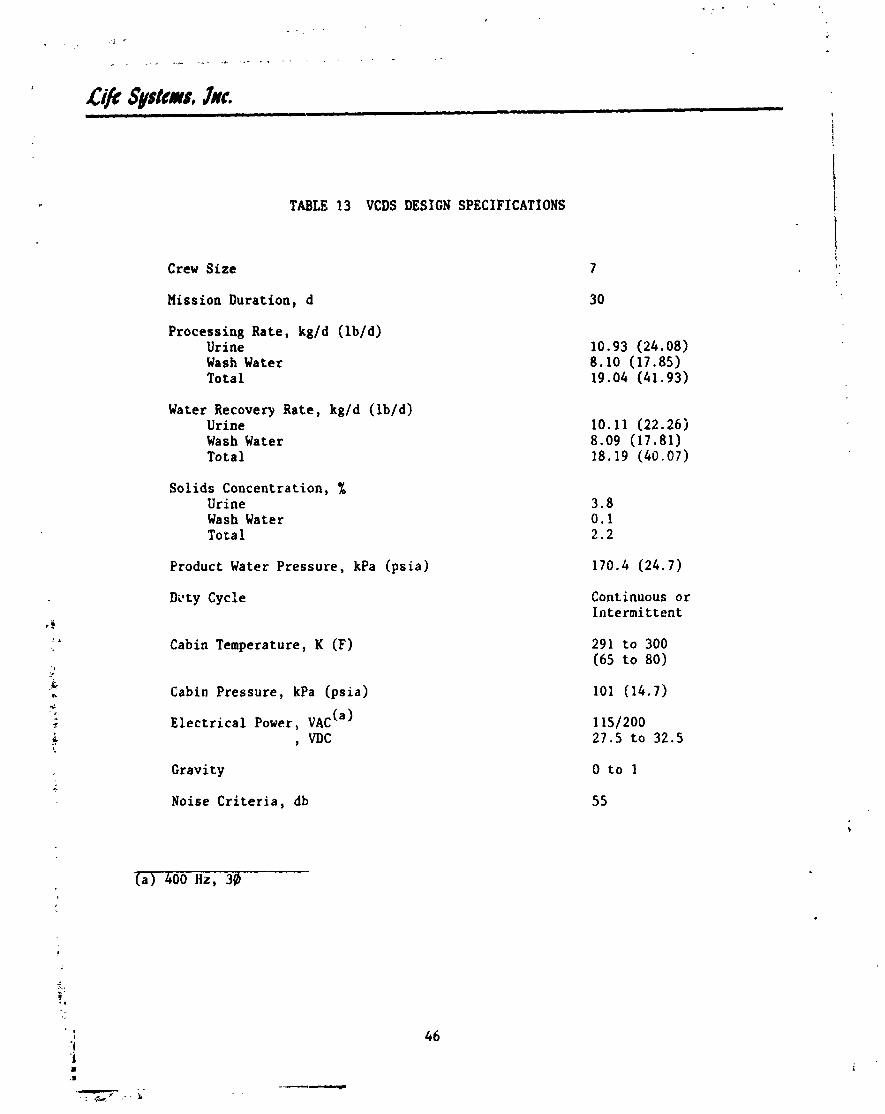
TABLE 13 VCDS DESIGN SPECIFICATIONS
Crew Size 7
30 Mission Duration, d
Processing Rate, kg/d ( lb /d) Urine Wash Water Total
Water Recovery Rate, kg/d ( lb/d) Urine Wash Water Tota l
Sol ids Concentration, % Urine Wash Water Total
Product Water Pressure, kPa (p s i a ) 170.4 (24.7)
Dvty Cycle Continuous or In te rmi t ten t
Cabin Temperature, K (F)
Cabin Pressure, kPa (p s i a ) 101 (14.7)
E l e c t r i c a l Power, VAC (a
, VJIc
Cravi t y 0 t o I
Noise C r i t e r i a , db 55
(a) 400 Hz, 3@


f o r reprocess ing. A bac te r ia / f low check va lve is used t o prevent back con- tamination o f t h e product water stream.
S t i l l p ressure i s maintained by t h e p ressure c o n t r o l module us ing space vacuum. The space vacuum i n t e r f a c e a l lows noncondensibles, wi th a smal l amount of water vapor, t o be continuously purged from t h e VCDS.
Design F lex ib i l i ty /Opt ions . The VCDS i s f l e x i b l e t o changes i n mission requ i re - ments. The VCDS can opera te over t h e e n t i r e four-person t o t en-p t r son range by simply using t h e wastewater s t o r a g e tank a s an accumulator assuming t h a t t h e nominal seven-person process ing r a t e i s t h e average requ i red process ing r a t e f o r t h e mission. Should a more optimized VCDS design be d e s i r e d , t h e compres- s o r p ressure r a t i o and s t i l l speed can be ad jus ted t o optimize t h e water recovery func t ion f o r d i f f e r e n t nominal o r average process ing r a t e s .
A l l components shown i n Figure 19 a r e f l i g h t mainta inable t o t h e component l e v e l assuming nero leakage l i q u i d - l i n e maintenance disconnect f i t t i n g s a r e used. Depending on mission l eng th and r e l i a b i l i t y g o a l s , redundant components o r spares can be included i n t h e des ign t o enhance r e l i a b i l i t y o r i n c r e a s e mission dura t ion . The p resen t subsystem has been designed f o r 30 days and i s l imi ted by t h e s i z e of t h e r e c j c l e tank. F a i l - s a f e opera t ion is accomplished using t h e water s to rage tanks on-board t h e S h u t t l e t o accumulate wastewater and supply po tab le water when t h e VCDS i s nonoperat ional .
Design Data. The design p o i n t f o r t h e VCDS i s a seven-person crew s i z e which corresponds t o a u r ine and wash water process ing r a t e of 19.0 kg/d (41.9 lb /d ) . Increases i n t h e wastewater product ion r a t e a r e accommodated using t h e waste- water s to rage tank a s an accumulator. Operation a t l e s s than t h e se- en-person l e v e l i s e a s i l y met by reducing t h e duty c y c l e f q r t h e VCqS. The s t i l l requ i red f o r t h e VCDS design has a s u r f a c e a r e a of 0.19 m' (2.0 f t ). The VCDS opera t - i n g c h a r a c t e r i s t i c s a r e presented i n Table 14.
Com~anent Weight, Power and Heat Re jec t ion . Component weight, power and h e a t r e j e c t i o n es t imates f o r t h e seven-person VCDS design a r e given i n Table 15. he s t i l l accounts f o r approximately 50% of t h e subsystem-weight. The o t h e r major weight f a c t o r s a r e t h e recyc le t ank , l i q u i d s pump and packaging. Packag- ing was estimated a t 20%. The power requirements were d iv ided i n t o AC and DC power.
Packaging
Figure 21 shows t h e S h u t t l e seven-person c a p a c i t y VCDS packaging conf igura t ion . The o v e r a l l subsystem dimensions a r e 64 x 30 x 71 cm (25 x 12 x 28 i n ) . The subsystem i s designed t o f i t under t h e mid-deck f l o o r and i n t e r f a c e d i r e c t l y with t h e O r b i t e r wastewater and water s t o r a g e t anks . This l o c a t i o n f o r t h e VCDS assumes t h a t t h e base l ine CO removal subsystem i s replaced by t h e EDC thereby e l imina t ing t h e need f o r $he LiOH c a n i s t e r s s t o r a g e racks . The VCDS i s designed t o mount d i r e c t l y t o t h e Shut l e f l o o r suppor t s . The seven-per on
3 5 VCDS r ~ q u i r e s a volume of 0.14 m (4 .9 f t ) which i s on ly 21% of t h e 0.65 m 5 (23 f t ) reserved f o r s t o r a g e of t h e S h u t t l e LiOH c a n i s t e r s .

TABLE 14 SHUTTLE VCDS OPERATING CHAHACTERISTICS
Water Recovery Rate, kg/d (lb/d)
Duty Cycle, %
Condenser Pressure, kPa (psia)
Compressor Pressure Differential, kPa (psid)
Fluids Pump Flow Rate, kg/h (lb/h) Feed Recycle Product
3 3 Purge Gas Flow Rate, n~ /h (ft /h)
Purge Gas Water Loss, %
Subsystem Specific Energy, W-h/kg (W-h/lb)
Solids Concentration (Max), %
Recycle Tank Capacity (210 person-days) , kg (I b)
-- -- (a) Urine and wash water only
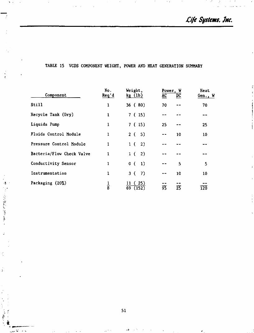
TABLE 15 VCDS COMPONENT WEIGHT, POWER AND HEAT GENERATION SUMMARY
Component
Still
Recycle Tank (Dry)
Liquids Pump
Fluids Control Module
Pressure Control Module
BacteriaIFlow Check Valve
Conductivity Sensor
Instrumentation
Packaging (20%)
No. Req' d
1
1
1
1
1
1
1
1
1 - 8
Weight, Power, W Heat kg (lb) AC - DC - Gen. , W


Subsystem Characteristics
The VCDS characteristics for the seven-person design are presented in Table 16. The VCDS recovers approximately 95% of the wastewater processed or 18.2 kgld (40.1 lb/d) . The power requirements are divided into AC and DC requirements. The heat load is the sensible heat given off by the power consuming components.
Expendables are required for the VCDS. Approximately 0.5% of the water pro- cessed is lost with the purge gas to vacuum. This amounts to approximately 0.1 kgld (0.2 lbld). The recycle tank can also be considered an expendable since its size varies with mission duration and water processing rate.
Vehicle Integration for Supplementary Heat Rejection
The VCDS hardware is designed to interface directly with existing Shuttle Water Management System (WMS) components. The existing Shuttle bater manage- ment block diagraw is presented in Figure 22. The location of the VCDS within the Shuttle WMS is shown in Figure 23. In addition to the VCDS, the Shuttle water recovery subsystem for supplementary heat rejection would require that a pretreat unit, a post-treat unit and a bacterialfilter check valve be added to the WMS components. The VCDS WRS characteristics are presented in Table 17. The VCDS obtains water for processing from one of the present Shuttle wastewater storage tanks. Urine and wash water are processed through the VCDS. Condensate is processed primarily through the pretreat although it can also be processed through the VCDS via the wastewater storage tank. The VCDS product water, along with condensate, passes through the post-treat unit and is stored in a product water storage tank until needed by the flash evaporators for supple- mentary heat rejection. The product water tank is a converted wastewater storage tank. The bacterialflow check valve isolates the product water from the existing Shuttle potable water tanks. Both the VCDS product water and stored potable water can be used for suppleffientary heat rejection.
The VCDS requires only three Shuttle mechanical interfaces: wastewater from the storage tank, overboarded vent and 'product water to the storage tank via post-treat. All resources, including the required number of water tanks, pre- sently exist on the Shuttle.
Vehicle Integration for Potable Water
The location of the VCDS within the Shuttle WMS for potable water recovery is presented in Figure 24. In addition to the VCDS, the potable Water Recovery Subsystem requires a pretreat unit, post-treat, ACIDD, WQM and a three-way valve. The VCDS interfaces with the Shuttle water management components for potable water recovery in the same manner as it did for supplementary heat rejection water recovery. The Water Recovery Subsystem requires a residual
. biocide and a WQM to monitor product water quality for acceptabil.ity. The Shuttle potable water recovery system component characteristics are shown in Table 18.
The VCDS interfaces as part of a potable WRS are identical to those required for supplementary heat rejection water recovery. All required resources presently exist on the Shuttle.
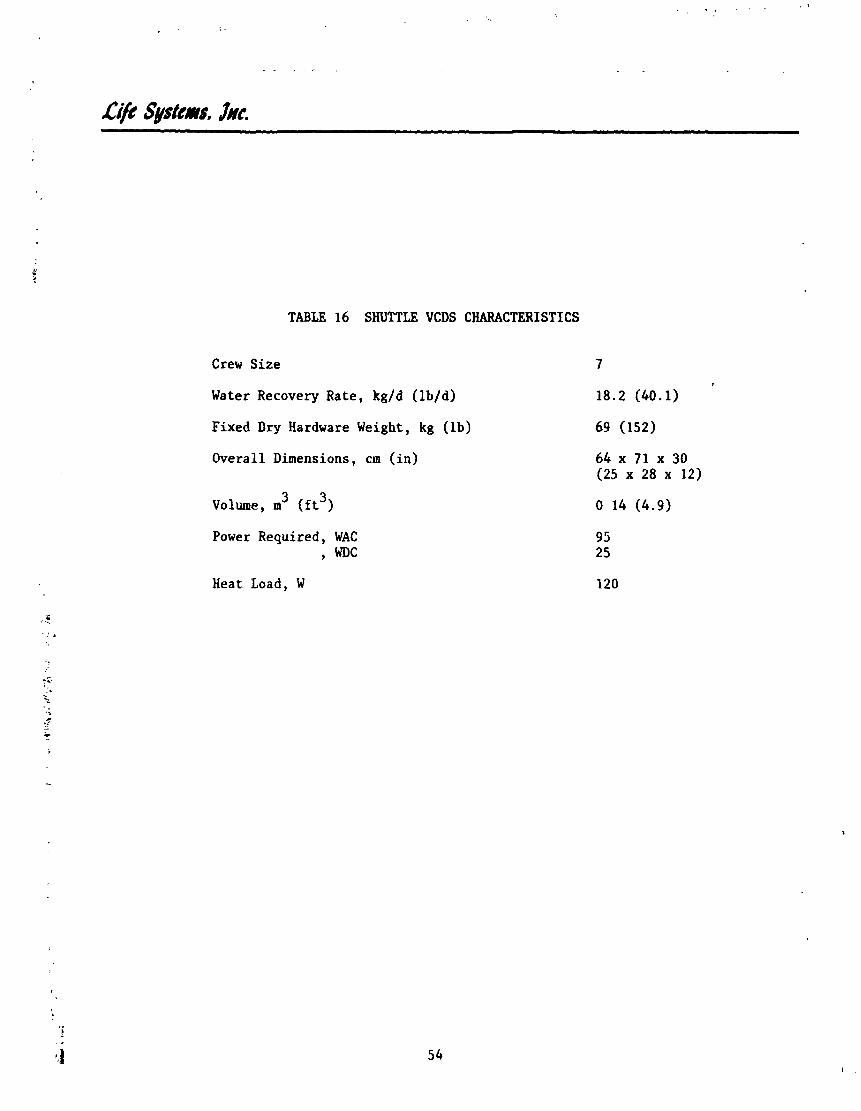
TABLE 16 SHUTTLE VCDS CHARACTERISTICS
Crew Size
Water Recovery Rate, kg/d (lb/d)
Fixed Dry Hardware Weight, kg (lb)
Overall Dimensions, cm (in)
3 3 Volume, m (ft )
Power Required, WAC 9 WDC
Heat Load, W

A/L
Ven
t
f
1 1 C
ond
end
ate
--B
=
Fu
el
Ce
ll
Wat
er
Con
den
sate
C
oll
ecti
on
-
-
J
Was
te
Sto
rage
T
anks
Wat
er T
o F
lash
Eva
p.
Po t
ab
le
Wat
er U
se
Pot
able
Wat
er T
anks
FIGURE 22
EXISTING SHUTTLE WATER MANAGEMENT BLOCK DIAGRAM

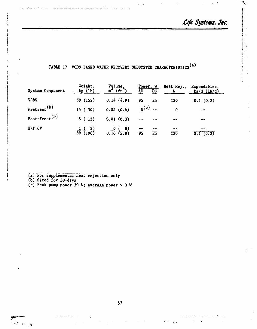
Weight, V ~ l m e , Power, W Heat Rej . , Expendables, System Component kg ( l b ) m ( f t 1- AC - DC W kg/d ( W d ) - VCDS 69 (152) 0.14 (4.9) 95 25 120 0.1 (0.2)
P r e t r e a t (b) 14 ( 30) 0.02 (0.6) &) -- 0 -- Post-Treat (b 5 ( 12) 0.01 (0.3) -- -- - - --
(a) For supplemental hea t r e j ec t ion only (b) Sized f o r 30-days (c) Peak pump power 30 W; average power + 0 W


TABLE 18 VCDS-BASED POTABLE WATER RECOVERY SYSTEM CHARACTERISTICS
System Component
VCDS
Pretreat (b
Post-Treat (b
ACIDD
WQM
Three-Way Valve
Weight, Vglume3 kg (lb) m (ft
69 (152) 0.14(4.9)
14 ( 30) 0.02 (0.6)
5 ( 12) 0.01 (0.3)
1 ( 3) O ( 0)
2 ( 4) O ( 0)
1 ( 2) O ( 0) !Em 6Xl33J
Power, W AC - DC - 95 25
,(c) -- - - -- 6 --
- - 4
Heat Rej . , Expendables, W kgJd (lb/d)
120 0.3 (0.7)")
0 0.2 (0.5)
- - 0.2 (0.4)
6 - - 4 - -
la) Includes water vapor loss to vent and recycle tank (b) Sized for 30 days (c) Peak pump power 30 W; average power * 0 W (d) Only requires power to activate

,C@ S~stcms, lac.
Development S ta tus
The VCDS technology i s wel l es tab l i shed . Three preprc otype u n i t s have been fabricated: t he six-per VCDS f o r SSP appl ica t ion and two three-person VCDSs f o r RLSE. A photograph of LSI1s RLSE VCDS is presented i n Figure 25. The VCDS can be ava i lab le f o r f l i g h t appl ica t ion by 1983.
Water Recovery Subsystem Comparison
The VCDS-based WRS1s f o r supplementary hea t r e j ec t i on and potable water recovery were compared t o on-board s torage of water f o r Mission Options Two and Three (see Table 2). For comparison purposes it was assumed t h a t f o r on-board potable water s torage, wastewater is dumped overboard a s opposed t o on-board wastewater s torage f o r t he mission durat ion. Mission Option One was not considered f o r water recovery s ince power is supplied exclusively by f u e l c e l l s and s u f f i c i e n t water i s produced t o meet veh ic le needs.
For enhanced Orbi te r Mission Option Two s u f f i c i e n t potable water e x i s t s such t h a t the water recovered by the VCDS would be required f o r supplementary hea t r e j ec t i on only. For Mission Option Three, however, water i s not generated by the f u e l c e l l s and potable water requirements must be met by on-board s torage o r water recovery. The water recovery r a t e used f o r comparison was 29.3 kg/d (64.5 lb/d) which equals t he sum of the VCDS recovery r a t e (18.2 kg/d (40.1 lb /d) ) and the condensate recovery r a t e (11.1 kg/d (24.4 l b /d ) ) .
Mission Option Two
Table 19 summarizes t he WMS charac te r i s t - ics f o r supplementary hea t r e j ec t i on water recovery. The values given do not include those f o r t he e x i s t i n g Shu t t l e components such a s t he f i v e water tanks. The values l i s t e d f o r t h e VCDS include the addi t iona l WRS components required t h a t were presented i n Table 17. Expendables include process expendables and cryogen f o r power generat ion a t 3.33 kg/kW-d (7.34 lb/kW-d) f o r f u e l c e l l generated DC power. A 76% conversion e f f ic iency was sssumed f o r AC power. A cryogen s torage tankage penal ty of 100% was added t o the cryogen consumption r a t e .
Figure 26 shows the launch weight versus mission durat ion f o r ED0 t l iss ion Option Two fo r water s to rage and the VCDS. The launch weight savings a t t a i n - able using the VCDS-based water recovery system versus base l ine water s to rage is 696 kg (1,533 l b ) . Weight savings a r e a t t a i n a b l e using a VCDS water re- covery system a f t e r two days f o r a seven-person crew s i z e .
Mission Option Three
Table 20 presents t h e potable WHS c h a r a c t e r i s t i c s f o r da t e r s to rage and a VCDS water recovery system. The values used do not includc base l ine Shu t t l e components. The VCDS WRS includes a l l add i t i ona l components requirod f o r potable water recovery (see Table 19). Figure 27 shows the t o t a l equivalent launch weight comparisons f o r ED0 Micsion Option Three. Equivalent weight was used f o r t he f u l l c apab i l i t y power module s ince power and heat r e j ec t i on pena l t i e s must be considered when comparing the two approaches. Equivalent weight savings a t t r i b u t e d t o the VCDS water recovery system a r e 1,092 kg (2,405 l b ) f o r a nominal mission length of 30 days. The water recovery r a t e includes ur ine ,


Weight, (b) Power, W Heat. Rej . , Expendables, ( c )
System kg ( l b ) m ( f t AC - DC W - ---- kg/d ( l b / d )
Storage 0 (0) 0 (0) 0 0 0 42.4 (93.4)
VCDS 89 ( 1 9 6 ) ' ~ ) 0.16 ( ~ ~ 8 ) ' ~ ) 95 25 120 ' (2 .4)
- (a) For supplemental h e a t r e j e c t i o n only ( b ) Does no t inc lude b a s e l i n e O r b i t e r components weinht ( c j Includes cryogen f o r power generat ion-wif ' . tankage and process expendables ( 6 ) Includes 30-day capac i ty Recycle Tank, P r e t r e a t and POSL-Treat

'I'
10 15 20 25
Mi~eion Duration, d
FIGURE 26 WATER MANAGEMENT SYSTEM LAUNCX W E I m COMPARISON: KISSION OPTION TWO

TABLE 20 POTABLE WATER MANAGEMENT SYSTEMS CHARACTERISTICS
Weight, volyne, Pouer ,W H e a t R e j . , Expendables, (b Sys tern kg ( l b ) ( f t > AC - - DC W k d d ( W d )
Storage 0 (0) 0 (0) 0 0 0 42.4 (93.4)
V C D S ( ~ ) 92 (203)") 0.16 (5.8)") 101 29 130 0.7 (1 .6)
( a ) Does no t inc lude b a s e l i n e O r b i t e r components weight (b) For f u l l c a p a b i l i t y power module; only process expendables included (c ) Includes 30-day capac i ty Recycle Tank, P r e t r e a t and Post -Treat
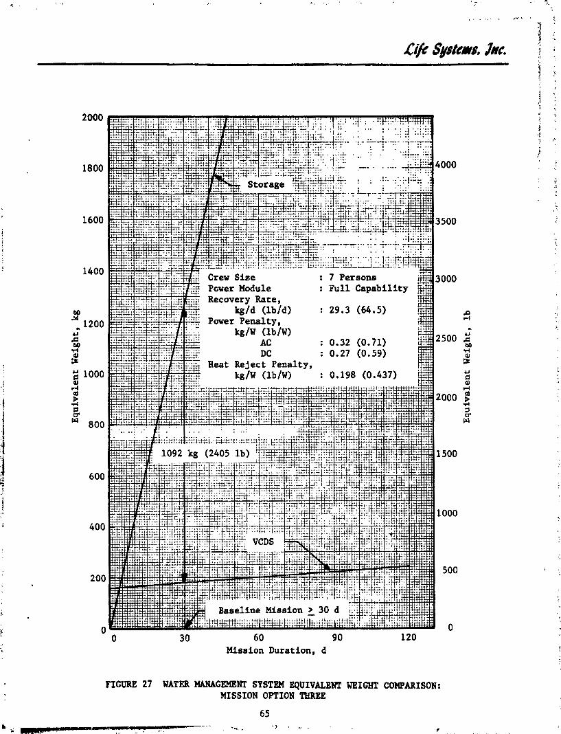
60 9 0 Mission Duration, d
FIGURE 27 WATER MANAGEMENT SYSTEM EQUIVALENT WEIGHT COMPARISON: MISSION OPTION THREE
65 4~ ~
- . .. . . ... , -.r.. , ' > .. . . . ..

wash water and condensate recovery. Weight savings for Mission Option Three occur for mission durations greater than four days for a crew size of seven.
Water Recovery Subsystem Evaluation Conclusions
The VCUS-based WRS for ED0 application has been evaluated for both supplemen- tary heat rejection and potable water recovery. The VCDS was shown to be clearly ;uperior to on-board water storage when fuel cell water is insufficient to meet Orbiter water requirements. Weight savings occur for mission durations as brief as two days for a seven-person crew.
COMBIMD C02 REMOVAL AND WATER RECOVERY
The C02 Removal and Water Recovery Subsystems evaluations for Shuttle applica- tion have been treated separately up to this section. The expendables penalty for water vented overboard by some CO removal subsystems, however, is deter- mined by Orbiter water requirements. '~lso, the post-treat portion of a WRS is affected by the CO removal subsystem selection since the condensate process- 2 ing requirements are different for each subsystem. The VCDS size remains the same since condensate is not processed by the VCDS still. Because the CO removal and water recovery functions affect each other, special consideraZion is given in this section to the impact of the combined functions on subsystem selection.
Combined CO removal and water recovery was not considered for Mission Option 2 One since water recovery is not required. For Mission Option Three the savings associated with combined CO removal and water recovery will be basically the 2 sum of the savings for the individual functions versus baseline Shuttle LiOH and water storage. The reason for this is that water vented overboard in Mission Option Three was considered an expendable penalty to the CO removal subsystems evaluated. Mission Option Two, however, is more difficuft to evaluate since the amount of additional water required for supplementary heat rejection will affect whether water recovery is needed and if so, how much.
The following sections discuss the effect of combining thr removal and water recovery functions for Mission Options Two and Three. I11 comparison assumptions made during the individual subsystem comparisons were retained unless specifically noted to the contrary.
Mission Option Two
The CO removal subsystems comparison presented earlier for Mission 3ption Two assume4 that sufficient water would be available for supplemental heat rejec- tion and the subsystems were not penalized for water vented overboard. The VCDS evaluation for Mission Option Two, however, assumed that additional supplemental heat rejection water would be required at a rate equal to or greater than that produced by the VCDS-based WRS. The impact of water recovery on C02 removai subsystem selection must therefore be considered.
Combined CO removal and water recovery was considered for two levels of additional ahuttle water requirements. These levels are based on the water
i ! . t recovery rate available when only condensate is processed and when condensate, ! t . I urine and wash water are processed. The condensate only water processing

rate was assumed to be the sum of the metabolic and EDC condensate generated or 14.3 kg/d (31.5 lb/d). The condensate, urine and wash water recovery rate was assumed to be the sum of the condensate (including EDC) and VCDS water recovery rates or 32.5 i g / d (71.6 lb/d) . Condensate Recovery
The result; of the combined functions as identified by the C02 removal sub- system are presented in Figure 28. The EDC and EDC/WVE subsystem fixed hard- ware weights were increased to include the additional components required for condensate recovery including a 100% plumbing and retrofit penalty. The HS-C/RH Subsystem does not require these additional components since the water vented overboard by this process is removed from the cabin air. The removal of latent heat from the cabin reduces the vehicle's heat rejection requirements and therefore the subsystem indirectly performs supplementary heat rejection. The HS-C/Water Save Subsystem wds not considered since supplementary heat rejection was assumed to be required.
The HS-C/RH Subsystem was penalized only for the additional water storage required to go from metabolic condensate requirements up to the assumed supple- mentary heat rejection water requirements. The EDC/WVE subsystem was penalized similarly. The EDC subsystem, however, with its additional condensate genera- tion, did not incur any additional water storage penalty.
As shown, the E3C subsystem is favored by supplementary heat rejection requL 1 re- ments of greater than or equal to 14.3 kgld (31.5 lb/d). A weight savings of 61 kg (134 lb) was attributed to the EDC over the HS-C/RH and EDC/WVE Subsystems. For water recovery rates below 11.1 kg/d (24.4 lh/d), the metabolic condensate generation rate, the results of the individual CO removal subsystems compari- 2 sons for Mission Option Two previously considered remain approximately the same since the fixed hardware penalty associated for condensate recovery with the EDC and EDC/WVE are small. For water recovery rates betwetnn these two values, the EDC with its additional water generation becomes more attractive as water recovery requirements increase.
Total Water Pecover~
The results of the combined CO removal and water recovery functions are 2 plesented in Figure 29. The regenerable CO removal subsystems include the
weight of a VCDS and other WRS cumponenls. he difference in size of the post-treat units requir6d for the HS-C ald EDC concepts was taken into account. Again, the HS-C/Water Save Subsystem was not considered since supplementary heat rejection is required. The ccmbined savings using a regenerable CO 2 removal subsystem and water recovery is significant. Again, the EDC Subsystem is sl.ightlp favored over the other CO removal concepts since it produces additional condensate that the other $0 removal subsystems do not. A weight savings of 64 kg (141 lb) was attribute8 to the EDC over the HS-C/RH and EDC/WVE Subsystems.
Mission Option Three
Potable water recovery is required for Mission Option Three. The combined .-avings associated with a regenerable CO removal subsystem and water recovery 2

Yission Duration, d
FIGURE 28 COMBINED C 0 2 REMOVAL AND CONDENSATE RECOVEBY: MISSION OPTION TWO

u 5 10 15 20
Mission Duration, d
FIGURE 29 COMBINED CO REMOVAL AND TOTAL M I S ~ O N OPTION TWO
69
25 30 u
WATER RECOVERY:
is the sum of the individual savings per subsystem. Figure 30 shows the combined equivalent weight savings for water recovery and CO removal. The amount of potable water required for seven persons is the s d of the wash water, water for food preparation and metabolic consumption or 35.4 kg/d (78 lb/d). The amount of recovered water available is 29.3 kg/d (64.5 lb/d) and increases to 32.5 kg/d (71.5 lb/d) when EDC condensate is considered. The additional water required is made up by on-board water storage. The EDC subsystem was again given credit for its additional condensate gene ratio^ and is clearly the lowest equivalent weight subsystem.
CONCLUSIONS
The following conclusions were drawn based on the study completed:
1.
2.
3 .
4.
5 .
6.
7.
Based on
1.
2.
3 .
Three enhanced Orbiter missions affect the selection of a Cop removal and water recovery subsystem. These mission options are characterized primarly by the power ~ystem selected which determines the avail- ability of cryogen and water.
Regenerable CO removal subsystems are superior to the expendable baseline LiOH Zo2 removal subsystem for all ED0 applications.
Both the EDC and EDC/WVE concepts are applicable to ED0 C02 removal.
An EDC-based C02 removal subsystem is preferred over a solid amine C02 removal subsystem for the three mission options evaluated.
Water recovery is superior to water storage.
A WRS is required for Mission Option Three to generate potable water. Water recovery requirements for Mission Option Two depend upon the supplementary heat rejection requirements which are not as yet defined.
Combined CO removal and water recovery, when applicable, favors the 2 E3C C02 removal subsystem since it produces additional condensate to satisfy the additional water requirements.
RECOMMENDATIONS
the study results, the following actions are recommended:
Replace the LiOH C02 Removal Subsystem with the EDC C02 Removal Subsystem for ED0 missions.
IJse the VCDS for water recovery when additional water is required as defined by mission specifications.
Continue to develop EDC/WVE for enhanced Orbiter application. The EDC/WVE offers the user the option of not using cryogenic E2 for the EDC .

Mieslon Duration, d
COMBINED C02 REMOVAL AND WATER RECOVERY: MISSION OPTION THREE
7 1
REFERENCES
"Future Orbital Power Systems Technology Requirements, lt NASA Couference ,+ ,. Publication 2058, Lewis Research Center Symposium, Cleveland, OH; May and June, 1978.
Craig, J. W. and DaRos, C. J., "An Orbital Service Module Systems Concept," AIAA Paper No. 38-1694, AIAA Conference on Large Space Platforms: Future Needs and Capabilities, Los Angeles, CA; September, 1978.
Mordan, G. W., "25 kW Power Module: First Step Beyond the Baseline STS," A I M Paper No. 78-1693, A I M Conference on Large Space Platforms: Future Needs and Capabilities, Los Angeles, CA; September, 1978.
Chapel, F. G; Martin, D. A. and Gore, D. C., "Extended Duration Orbiter Life Support System Options," ASME P~blication 78-ENAs-31, Intersociety Conference on Environmental Systems, San Diego, CA; July, 1978.
"Concept Definition for an Extended Duration Orbiter ECLSS," NAS9-14782, SVHSER 7185, Hamilton Standard, Windsor Locks, CT; September, 1977.
Kleiner, G. N., "Extended Duraticn Orbiter Life Support Definition," ASME Paper No. 78-ENAs-42, Intersociety Conference on Environmental Systems, San Diego, CA; July, 1978.
Wynveen, R. A.; Schubert, F, H. and Powell, J. D., "One-Man Self-contained C02 Concentrating System" Final Report, NASA CR-114426, ER-131-16, Life Systems, Inc., Cleveland, OH; March, 1972.
Powell, J. D.; Schubert, F. H.; Marshall, R. D. and Shwnar, J. W., "Six-Man, Self-contained Carbon Dioxide Concentrator Subsystem," Final Report, NASA CR-114743, ER-134-32, Life Systems, Inc., Cleveland, OH; June, 1974.
Kostell, G. D.; Schubert, F. H.; Shumar, J. W.; Hallick, T. M. and Jensen, F. C. , "Six-Man, Self-contained Carbon Dioxide Concentrator Subsystem for Space Station Prototype (SSP) Application, " Final Report, NASA CR- 114742, ER-170-34, Life Systems, Inc., Cleveland, OH; May, 1974.
Schneider, J. J.; Schubert, F. H.; Hallick, T. M. and Woods, R. R., t'Electrochemical Carbon Dioxide Concentrator Advanced Technology Tasks," Final Report, NASA CR-137732, ER-170E-4, Life Systems, Inc., Cleveland, OH; October, 1975.
Schubert, F. H.; Woods, R. R.; Hallick, T. M. and Heppner, D. B., "Tech- nology Advancement of the Electrochemical CO Concentrating Process," Annual Report, NASA CR-151995, ER-258-10, ~ i t e Systems, Inc., Cleveland, OH; May, 1977.
Schubert, F. H.; Marshall, R. D.; Quattrone, P. D. and Wynveen, R. A,, "Development of a Three-Man Preprototype CO Collection Subsystem for Spacecraft Application," ASME Paper No. 77-~NAS-19, Intersociety Con- ference on Environmental Systems, San Francisco, CA; July, 1977.

13. Schubert, F. H. and Marshall, R. D., "Integrated Water Vapor Electrolysis and Electrochemical Depolarized Concentrator," Annual Status Report, ER-192, Life Systems, Inc., Cleveland, OH; April, 1973.
14. Schubert, F. H.; Marshall, R. D.; Hallick, T. M. and Woods, R. R., "One-Man Electrochemical Air Revitalization System Evaluation," Final Report, ER-284-4, Life Systems, Inc. , Cleveland, CH; July, 1976.
15. Marshall, R. D.; Woods, R. R.; Hallick, T. M. and Schubert, F. H., "Develop- ment of a Three-Man Preprototype Independent Air Revitalization Subsystem (IARS)," ASHE Paper No. 77-ENAs-31, Intersociety Conference on Environ- mental Systems, San Francisco, CA; July, 1977.
16. Lantz, J. B.; Schubert, F. H.; Jensen, F. C. and Poweli, J. D. "Advanced Combined Iodine Disperiser and Detector ,I' Final Report, ER-277-4, Life Systems, Inc., Cleveland, OH; January, 1977.
17. West, S. ; Chrisos, J. and Baxter, W., "Water Quality Monitor," Final Report, Orion Research, Inc., Cambridge, MA; March, 1979.
18. "Extended Guration Orbiter ECLSS Study Volume I," SVHSER 7190, Rev. A, Hamilton Standard, Windsor Locks, CT; May, 1978.
19. "Modular Space Station Phase B Extension, Volume IV: Subsystems Analysis," Contract NAS9-9953, MSC 02471, North American Rockwell, Downey, CA; January, 1972.
20. "Trade Study for Water and Waste Management Concepts - Task 7, Support Special Analysis Report," MDC G5853, Contract NAS9-13404, McDonnell Douglas.
21. "Waste Management Program," Report No. 25,158, Contract NAS9-1680, The Marquardt Corporation, Van Nuys, CA; February, 1965.
22. Nuccio, P. P. and Jasionowski, W. J., "Automatic Water Recovery System," AMRL-TR-67-155, General American Research Division, General American Transportation Corporation, March, 1968.
23. Rambenek, R. A.; Nuccio, P. P.; Hurley, T. L. and Jasionowski, W. J., "Upgrading and Extended Testing of the MSC Integrated Water and Waste Management Hardware," Contract NAS9-9191, Final Report, Chemtric, Inc., Rosemont, IL; May, 1972.
24. Bambenek, R. A.; Nuccio, P. P. and Hurley, T. L., "Extended Testing of Compression Distillation," ASME Paper No. 72-ENAv-1, Environmental Control & Life Support Systems Conference, San Francisco, CA; August, 1972.
25. Reveley, W. F. and Nuccio, P, P., "Design and the Parametric Testing of the Space Station Prototype Integrated Vapor Compression Distillation Water Recovery Module," ASME Paper No. 75-ENAs-37, Intersociety Conference on Environmental Systems, San Francisco, CA; July, 1975.

26. Johnson, K. L.; Nuccio, P. P. and Reveley, W. F., "Improved Waste Water Vapor Compression Distillation Technology," ASME Payer No. 77-ENAs-20, Intersociety Conference on Environmental Systems, San Francisco, CA; July, 1977.
27. "Requirements/Def inition Document, Atmospheric Revitalization," SD72-SH- 0106-1, Contract NAS9-14000, Rockwell International, Downey, CA; October, 1976.
28. "Requirements/Definition Document, Food, Water, & Waste, Volume 6-2," SD72-SH-0106-2, Contract NAS9-14000, Rockwell International, Downey, CA; June, 1976.

APPENDIX 1 SHUTTLE AIR COOLED EDC SUBSYSTEM
Figure
Al-1 Shuttle EDC Schematic (Air Cooled)
A1-2 Shuttle EDC Detailed Schematic (Air Cooled)
Table -- Al-1 EDC Subsystem Component Weight, Power and Heat
Generation Sumaary (Air Cooled)
A102 Shuttle EDC Subsystem Characteristics S m a r y (Air Cooled)


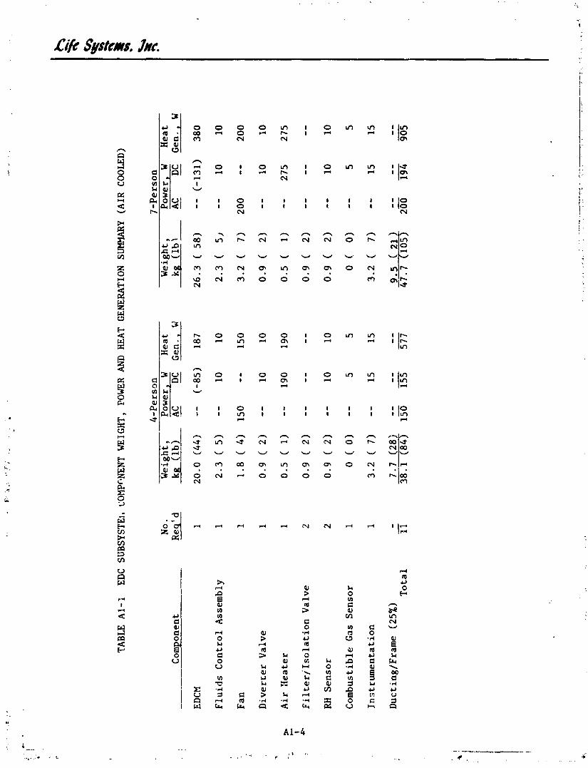
TABLE A
l-'L
EDC SUBSYSTEl, COM
PC#E
NT WEIGHT,
POW
ER A
ND HEAT
GENERATION SUMMARY (A
IR CO
OLED
)
Component
EDCM
Fluids C
ontrol Assembly
Fan
Diverrer Valve
Air Xeater
C
I FilterjIsolation Valve
RH Sensor
Combustible 63s Sensor
Instrumentation
Ducting/Frame (25%)
Total
No.
Req' d
1 1 1 1 1 2
2 1 1 - -
'1 1
4-Person
7-Person
Weight,
Power, W
Heat
Weight,
Power, W
Heat
kg (lb)
AC -
DC -
Gen
., W
kg (lb)
AC
DC
Gen. ,
W -
-- -
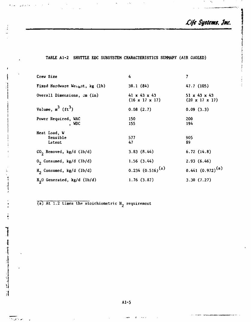
TABLE A1-2 SHUTTLE EDC SUBSYSTEM CHARACTERISTICS SlJMl'UWY (AIR COOLED)
Crew S i z e
Fixed Hardware Weikat, kg ( l b )
Overall Dimersions , an ( i n )
3 3 Volune, m ( f t )
Power Required, WAC , WDC
Heat Load, W Sens ib le La t e n t
C02 Removed, kg/d ( lb /d)
O2 Consumed, kg/d ( lb/d)
H2 Consumed, kg/d ( lb/d)
H20 Generated, kg/d ( lb /d)
m. 2 times the s to ichiometric H requirement 2

APPENDIX 2 SHUTTLE AIR COOLED EDC/WVE SUBSTSTEX
Figure
A2-1 Shuttle EDC/WE Schematic (Air Cooled)
A2-2 Shuttle EDC/WVE Detailed Schematic (Air Cooled)
A2-1 EDC/WVE Subsystem Component Weight, Power and Heat Generation Swxnary (Air Cooled)
A2-2 Shuttle EDC/WVE Subsystem Characteristics Summary (Air Cooled)
Page
A2-2
A2-3


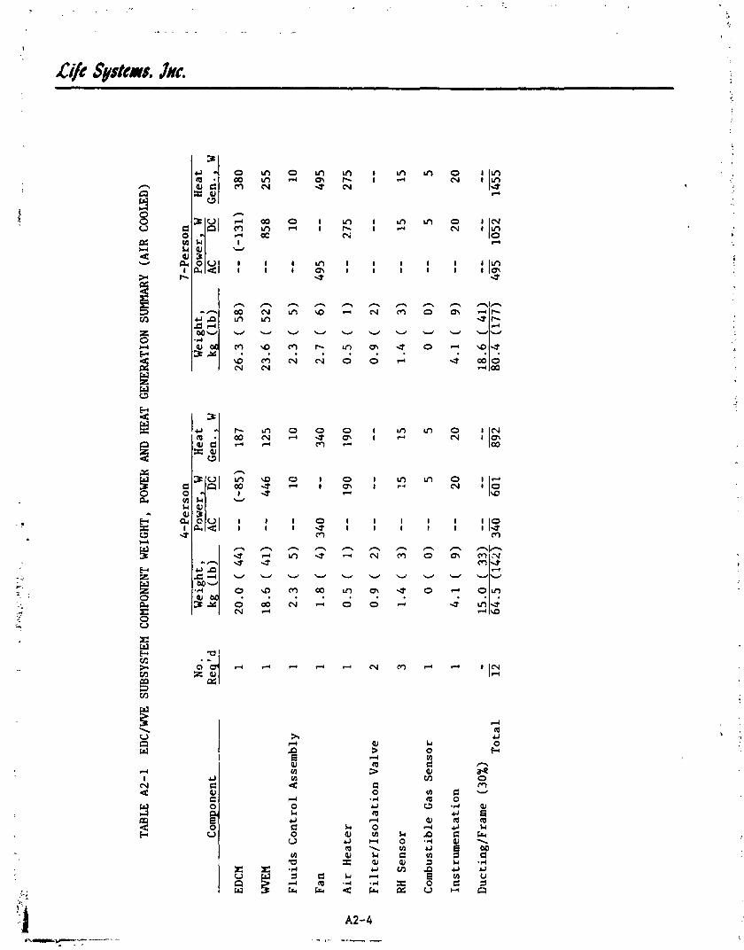
CYt Systems, Jxr.

TABJ4E A2-2 SHUTTLE EDC/WVE SUBSYSTEM CHARACTERISTICS SUMMARY (AIR COOLED)
Crew Size
1 Fixed Hardware Weight, kg (lb) !
1 Overall Dimensions, cm (in)
Volume, m3 (ft3)
Power Required, WAC , WDC
Heat Load, W Sensible Latent
C02 Removed, kg/d (lb/Q)
0 Consumed, kg/d (lb/d) 2
HZ Consumed, kg/d (lb/d)
H20 Generated, kg/d (lb/d)