Embed Size (px)
Citation preview
Co-ordinate Measuring Machines LH 108, LH 1010
PREMIUM-SELECT Models
Technical Data
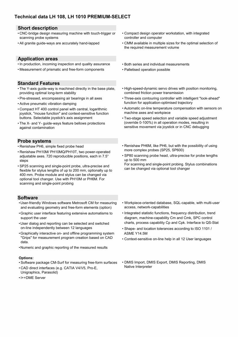
Technical data LH 108, LH 1010 PREMIUM-SELECT
Short description • CNC-bridge design measuring machine with touch-trigger or scanning probe systems
• All granite guide-ways are accurately hand-lapped
Application areas • In production, incoming inspection and quality assurance • Measurement of prismatic and free-form components
Standard Features • The Y-axis guide-way is machined directly in the base plate, providing optimal long-term stability
• Pre-stressed, encompassing air bearings in all axes • Active pneumatic vibration damping • Compact HT 400 control panel with central, logarithmic joystick, "mouse function" and context-sensitive function buttons. Selectable joystick's axis assignment
• The X- and Y- guide-ways feature bellows protections against contamination
• Compact design operator workstation, with integrated controller and computer
• CMM available in multiple sizes for the optimal selection of the required measurement volume
• Both series and individual measurements • Palletised operation possible
• High-speed-dynamic servo drives with position monitoring, combined friction power transmission
• Three-axis contouring controller with intelligent "look-ahead" function for application-optimised trajectory
• Automatic on-line temperature compensation with sensors on machine axes and workpiece
• Two-stage speed selection and variable speed adjustment (override 0-100%) in all operation modes, resulting in sensitive movement via joystick or in CNC debugging
Probe systems • Renishaw PH6, simple fixed probe head • Renishaw PH10M/ PH10MQ/PH10T, two power-operated
adjustable axes. 720 reproducible positions, each in 7.5° steps
• SP25 scanning and single-point probe, ultra-precise and flexible for stylus lengths of up to 200 mm, optionally up to 400 mm. Probe module and stylus can be changed via optional tool changer. Use with PH10M or PH6M. For scanning and single-point probing
Software • User-friendly Windows software Metrosoft CM for measuring and evaluating geometry and free-form elements (option)
• Graphic user interface featuring extensive automatisms to support the user
• User dialog and reporting can be selected and switched on-line independently between 12 languages
• Graphically interactive on- and offline programming system "Grips" for measurement program creation based on CAD data.
• Numeric and graphic reporting of the measured results Options: • Software package CM-Surf for measuring free-form surfaces • CAD direct interfaces (e.g. CATIA V4/V5, Pro-E, Unigraphics, Parasolid)
• I++DME Server
• Renishaw PH6M, like PH6, but with the possibility of using more complex probes (SP25, SP600)
• SP80 scanning probe head, ultra-precise for probe lengths up to 500 mm For scanning and single-point probing. Stylus combinations can be changed via optional tool changer
• Workpiece-oriented database, SQL-capable, with multi-user access, network-capabilities
• Integrated statistic functions, frequency distribution, trend diagram, machine-capability Cm and Cmk, SPC control charts, process capability Cp and Cpk. Interface to QS-Stat
• Shape- and location tolerances according to ISO 1101 / ASME Y14.5M • Context-sensitive on-line help in all 12 User languages
• DMIS Import, DMIS Export, DMIS Reporting, DMIS Native Interpreter
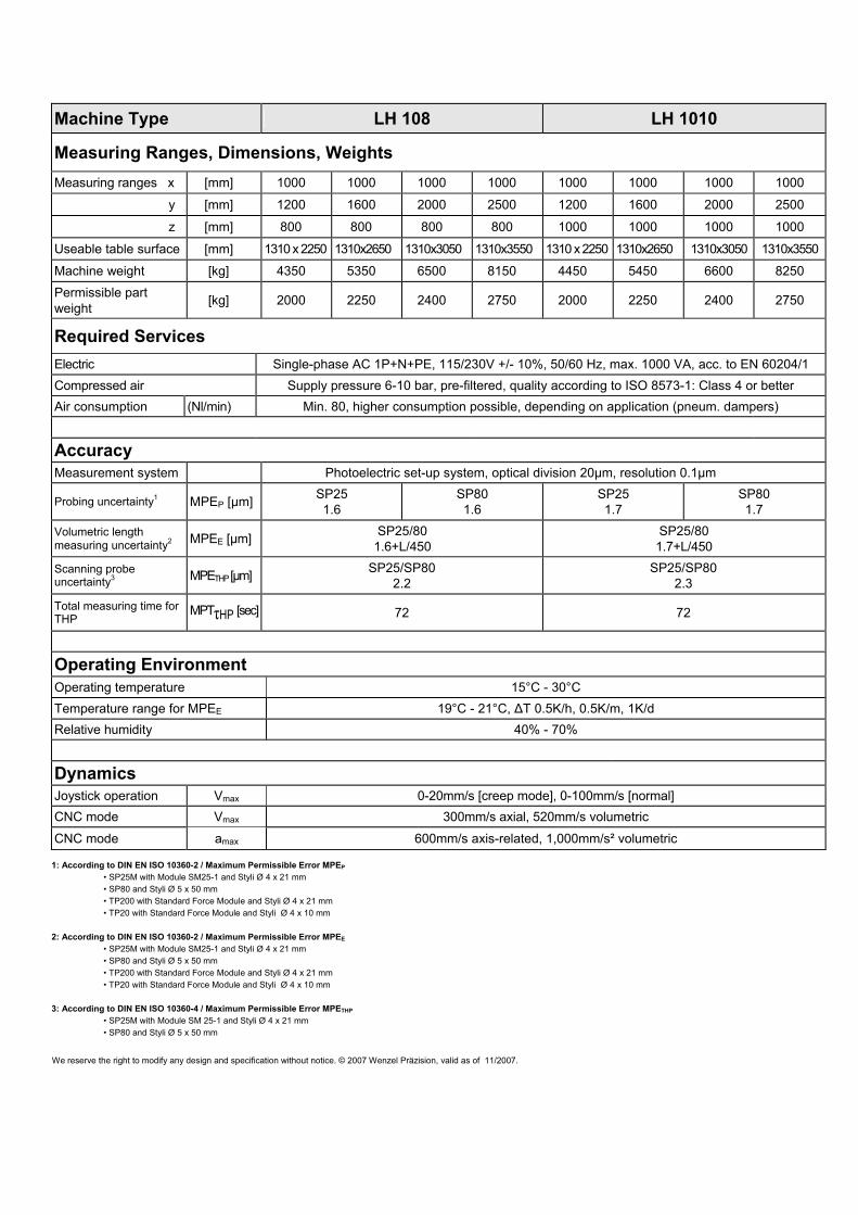
Machine Type LH 108 LH 1010
Measuring Ranges, Dimensions, Weights Measuring ranges x [mm] 1000 1000 1000 1000 1000 1000 1000 1000
y [mm] 1200 1600 2000 2500 1200 1600 2000 2500 z [mm] 800 800 800 800 1000 1000 1000 1000
Useable table surface [mm] 1310 x 2250 1310x2650 1310x3050 1310x3550 1310 x 2250 1310x2650 1310x3050 1310x3550
Machine weight [kg] 4350 5350 6500 8150 4450 5450 6600 8250 Permissible part weight [kg] 2000 2250 2400 2750 2000 2250 2400 2750
Required Services Electric Single-phase AC 1P+N+PE, 115/230V +/- 10%, 50/60 Hz, max. 1000 VA, acc. to EN 60204/1 Compressed air Supply pressure 6-10 bar, pre-filtered, quality according to ISO 8573-1: Class 4 or better Air consumption (Nl/min) Min. 80, higher consumption possible, depending on application (pneum. dampers)
Accuracy Measurement system Photoelectric set-up system, optical division 20µm, resolution 0.1µm
Probing uncertainty1 MPEP [µm] SP25 1.6
SP80 1.6
SP25 1.7
SP80 1.7
Volumetric length measuring uncertainty2 MPEE [µm] SP25/80
1.6+L/450 SP25/80 1.7+L/450
Scanning probe uncertainty3 MPETHP [µm] SP25/SP80
2.2 SP25/SP80
2.3
Total measuring time for THP
MPTτHP [sec] 72 72
Operating Environment Operating temperature 15°C - 30°C Temperature range for MPEE 19°C - 21°C, ΔT 0.5K/h, 0.5K/m, 1K/d Relative humidity 40% - 70%
Dynamics Joystick operation Vmax 0-20mm/s [creep mode], 0-100mm/s [normal] CNC mode Vmax 300mm/s axial, 520mm/s volumetric CNC mode amax 600mm/s axis-related, 1,000mm/s² volumetric
1: According to DIN EN ISO 10360-2 / Maximum Permissible Error MPEP • SP25M with Module SM25-1 and Styli Ø 4 x 21 mm • SP80 and Styli Ø 5 x 50 mm • TP200 with Standard Force Module and Styli Ø 4 x 21 mm • TP20 with Standard Force Module and Styli Ø 4 x 10 mm 2: According to DIN EN ISO 10360-2 / Maximum Permissible Error MPEE • SP25M with Module SM25-1 and Styli Ø 4 x 21 mm • SP80 and Styli Ø 5 x 50 mm • TP200 with Standard Force Module and Styli Ø 4 x 21 mm • TP20 with Standard Force Module and Styli Ø 4 x 10 mm 3: According to DIN EN ISO 10360-4 / Maximum Permissible Error MPETHP • SP25M with Module SM 25-1 and Styli Ø 4 x 21 mm • SP80 and Styli Ø 5 x 50 mm
We reserve the right to modify any design and specification without notice. © 2007 Wenzel Präzision, valid as of 11/2007.
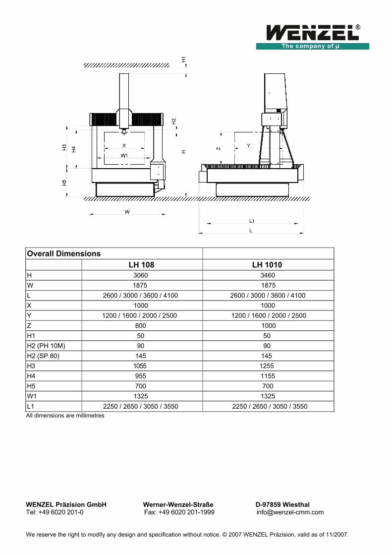
Overall Dimensions
LH 108 LH 1010 H 3060 3460 W 1875 1875 L 2600 / 3000 / 3600 / 4100 2600 / 3000 / 3600 / 4100 X 1000 1000 Y 1200 / 1600 / 2000 / 2500 1200 / 1600 / 2000 / 2500 Z 800 1000 H1 50 50 H2 (PH 10M) 90 90 H2 (SP 80) 145 145 H3 1055 1255 H4 955 1155 H5 700 700 W1 1325 1325 L1 2250 / 2650 / 3050 / 3550 2250 / 2650 / 3050 / 3550 All dimensions are millimetres WENZEL Präzision GmbH Werner-Wenzel-Straße D-97859 Wiesthal Tel: +49 6020 201-0 Fax: +49 6020 201-1999 [email protected] We reserve the right to modify any design and specification without notice. © 2007 WENZEL Präzision, valid as of 11/2007.


![Co ordinate geometry [toppersBlog.com]](https://img.pdfslide.us/doc/110x75/589c2eac1a28ab65248b68f9/co-ordinate-geometry-toppersblogcom.jpg)