Embed Size (px)
Citation preview
Co-Designing Accelerators and SoC Interfacesusing gem5-Aladdin
Yakun Sophia Shao§ Sam (Likun) Xi Vijayalakshmi Srinivasan† Gu-Yeon Wei David BrooksNVIDIA Research§ Harvard University IBM Research†
[email protected] {samxi,guyeon,dbrooks}@eecs.harvard.edu [email protected]
Abstract—Increasing demand for power-efficient, high-performance computing has spurred a growing number anddiversity of hardware accelerators in mobile and server Systemson Chip (SoCs). This paper makes the case that the co-designof the accelerator microarchitecture with the system in whichit belongs is critical to balanced, efficient accelerator microar-chitectures. We find that data movement and coherence man-agement for accelerators are significant yet often unaccountedcomponents of total accelerator runtime, resulting in misleadingperformance predictions and inefficient accelerator designs. Toexplore the design space of accelerator-system co-design, wedevelop gem5-Aladdin, an SoC simulator that captures dynamicinteractions between accelerators and the SoC platform, andvalidate it to within 6% against real hardware. Our co-designstudies show that the optimal energy-delay-product (EDP) ofan accelerator microarchitecture can improve by up to 7.4×when system-level effects are considered compared to optimizingaccelerators in isolation.
I. INTRODUCTION
In the era of diminishing returns from technology scaling,hardware acceleration is widely used to gain performance,power, and energy improvements [1]. Accelerators are nowan integral component in modern SoCs, powering a varietyof applications like video decoding, image processing, cryp-tography, machine learning, and more [2], [3], [4], [5], [6].
Accelerators are often designed as standalone IP blocksthat communicate with the rest of the system using a DirectMemory Access (DMA) interface. This modularity simplifiesIP design and integration with the rest of the system, leavingtasks like data movement and coherency management to soft-ware device drivers. As a result, the costs of these overheadsare hard to predict and accommodate for at accelerator designtime. Our detailed characterization of accelerator behaviorshows that the combination of just these two effects canoccupy over 40% of the total runtime. Hence, when it comesto accelerator design, architects must take a holistic view ofhow they interact in the overall system, rather than designingthem in isolation.
Fundamentally, all systems should be designed in a waythat balances the bandwidth of the memory interface withthe amount of compute throughput. An overly aggressive
This work was done while Y.S. Shao was a graduate student at HarvardUniversity.
design will have more computational units than the mem-ory interface can supply, leading to wasted hardware andadditional leakage power. We identify three major system-level considerations that strongly affect accelerator design:local memory interface, cache coherency management, andbehavior under shared resource contention.
The typical local memory interface is DMA, a push-basedsystem that requires software to setup bulk transfers andmanage coherency. An alternative is to embed a hardware-managed cache with the accelerator design, leading to afine-grained, pull-based memory system that loads data on-demand and transparently handles coherency state. Despitethese conveniences, caches are rarely used in accelerators dueto hardware overheads leading to power and area penalties.However, there has been growing interest from industry inproviding coherent accelerator cache interfaces [7], [8], [9]for the ease of programmability. We investigate the system-level considerations for both approaches to understand wheneach is preferable.
Such studies require detailed simulation infrastructure forheterogeneous accelerator-rich platforms like SoCs. There isa wide selection of CPU simulators [10], [11], [12] and stan-dalone accelerator simulators like Aladdin [13]. However,existing SoC simulators are unable to model dynamic inter-actions between accelerators and the memory system [14]. Inthis paper, we introduce gem5-aladdin, which integrates thegem5 system simulator with the Aladdin accelerator simula-tor to enable simulation of SoCs with complex accelerator-system interactions. We validate gem5-aladdin against theXilinx Zynq platform and achieve less than 6% error.
We demonstrate that co-designing accelerators withsystem-level considerations has two major ramifications foraccelerator microarchitectures that are not yet fully un-derstood in the literature. First, datapaths should be lessaggressively parallel, which results in more balanced designsand improved energy efficiency compared to acceleratorsdesigned in isolation. Second, the choice of local memoryinterfaces is highly dependent on the dynamic memorycharacteristics of the accelerated workload, the system ar-chitecture, and the desired power/performance targets. Weshow that accelerator-system co-design can improve energy-delay-product by up to 7.4× and on average 2.2×.978-1-5090-3508-3/16/$31.00 c© 2016 IEEE
0.0 0.2 0.4 0.6 0.8 1.0 1.2 1.4 1.6Latency (ms)
0
5
10
15
20
25
30
35
40Pow
er
(mW
)
Lanes: 16Ports: 16
Isolated Optimal:
Co-designed Optimal:Lanes: 4Ports: 8
Isolated
Co-designed
Fig. 1: Design space exploration for stencil3d for both isolatedand co-designed cases.
II. MOTIVATION AND BACKGROUND
In this paper, we use the term “accelerator” to refer toan application-specific hardware block. These acceleratorsare comprised of multiple customized datapath lanes, andcustomized local memories. Each lane is a chain of functionalunits controlled by finite state machines. When the localmemory is comprised of scratchpads, each scratchpad can bepartitioned into smaller arrays to increase memory bandwidthto the lanes. Such accelerators are representative of recentacademic proposals [3], [15], [16], [17], [18], [19], [20] andcommercial designs [21], [22], [23].
A. Co-design: A Motivating Example
To demonstrate the differences between isolated vs. co-designed accelerators, we perform a design sweep explo-ration for both scenarios on a 3D stencil kernel. We sweepcompute parallelism and scratchpad partitioning. Computeparallelism is described by the number of datapath lanes.Figure 1 shows these two design spaces.
We consider an accelerator designed in isolation to be onethat focuses design optimization on the computation phase.This design space (blue circles) leans towards more parallel,power-hungry designs, as exemplified by the isolated energy-delay-product (EDP) optimal design point. But if we accountfor effects like initial data movement, the design space(green triangles) shifts dramatically towards the lower right,preferring less parallel designs at lower power. If we takethe isolated EDP optimal design and then apply these systemeffects, we find that it is quite different from the co-designedEDP optimal point. Unaccounted data movement becomes asignificant part of total runtime, making aggressively paralleldatapaths unnecessary.
B. Typical CPU-Accelerator Communication
The existence of the difference between the two designspaces is due to how CPUs and accelerators traditionally
0.0 0.2 0.4 0.6 0.8 1.0Execution Time (ms)
DMA Store to DRAM
Accelerator Compute
DMA Load from DRAM
CPU Dcache Invalidate
CPU Dcache Flush
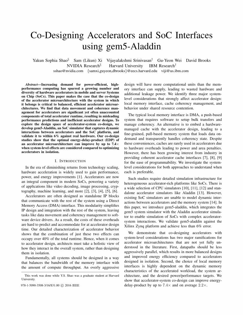
(a) md-knn execution time on the Zynq platform
aes-a
es
nw-nw
sort-
radix
viter
bi-vite
rbi
kmp-k
mp
gemm
-ncu
bed
sort-
mer
ge
gemm
-bloc
ked
md-g
rid
fft-tr
ansp
ose
fft-st
rided
sten
cil-st
encil
2d
sten
cil-st
encil
3d
md-k
nn
spm
v-cr
s
spm
v-ell
pack
bfs-queu
e
bfs-bulk
Avera
ge0.0
0.2
0.4
0.6
0.8
1.0
Execu
tion t
ime
Accel. Compute
DMA Transfer
CPU Flush
(b) Breakdown of flush, DMA, and compute time in MachSuite for 16-wayparallel designs.
Fig. 2: Data movement overheads on MachSuite.
communicate data. In this typical flow, DMA is the transfermechanism, but typical DMA implementations can onlyaccess main memory or LLC, so the CPU first flushes allinput data from private caches and invalidates the regionused to store return data [24]. Then it programs a DMAtransaction into the DMA engine and initiates the transfer.The accelerator begins execution after receiving all the dataand streams its output data via DMA back to main memorywhen it is done. The CPU, having invalidated that memoryregion from its caches, can now access the return datacorrectly.
For many benchmarks, this flow works quite well. DMAis quite efficient at copying large blocks of data, and accel-erators whose compute-to-memory ratios are large are wellserved by DMA. However, for other workloads with moreirregular memory access patterns, this flow can impose severeoverheads, because the accelerator must wait to receive allthe data before it can begin computation. As an example,Figure 2a shows the execution timeline for a 16-lane imple-mentation of an md-knn accelerator (a k-nearest-neighbormolecular dynamics), running on a Xilinx Zynq platform.As shown, the accelerator’s computation only occupies about25% of the total cycles, with the rest of the time spenton preparing and moving data. We expanded this study insimulation for all the MachSuite benchmarks [25] and findthat about half of them are compute-bound and the other halfdata-movement-bound, as shown in Figure 2b.
L2 Cache
CPU0
L1 Cache
System bus
MC
DRAMDRAM Lan
e 0
Lan
e 1
Lan
e 2
Lan
e 3
BUF0 BUF1
ARR0 ARR1 ARR2 ARR3
STR0 STR1
Lan
e 4
Lan
e 5
Lan
e 6
Lan
e 7
SPAD/DMA interfaceACCEL1
MEM
CPU1
L1 Cache
Scratchpad accelerator
DMA
Transfer descriptors
CHAN 0
CHAN 3
SRC ADDRDEST ADDR
LENGTH
SRC ADDRDEST ADDR
LENGTH
SRC ADDRDEST ADDR
LENGTH
SRC ADDRDEST ADDR
LENGTH
Channel selection
ACCEL0
MEM
Lan
e 0
Lan
e 1
Lan
e 2
Lan
e 3
L1 Cache
TLB
Cache controller
Cache accelerator
Design Parameter Values
Datapath lanes 1, 2, 4, 8, 16
Scratchpad partitioning 1, 2, 4, 8, 16
Data transfer mechanism DMA/cache
Pipelined DMA Enable/disable
DMA-triggered compute Enable/disable
Cache size 2, 4, 8, 16, 32, 64 (KB)
Cache line size 16, 32, 64 (B)
Cache ports 1, 2, 4, 8
Cache associativity 4, 8
Cache line flush 84 ns/line
Cache line invalidate 71 ns/line
Hardware prefetchers Strided
MSHRs 16
Accelerator TLB size 8
TLB miss latency 200 ns
System bus width 32, 64 (b)
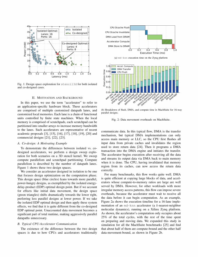
Fig. 3: An example SoC that can be modeled using gem5-Aladdin. The table on the right shows the set of design parameters that weswept in this work and their values; this is just a small subset of what can be configured.
Clearly, DMA is not an optimal solution for some work-loads. One alternative, as mentioned earlier, is to replacepush-based DMA with pull-based hardware-managed caches.In recent years, the scope of workloads that we desire toaccelerate has widened from dense computational kernels tomore irregular applications which could benefit from a lessrigid memory system. Although caches have seldom beenused for accelerators, the increased workload diversity mo-tivates a more comprehensive study of new CPU-acceleratorcommunication strategies.
III. MODELING INFRASTRUCTURE
Figure 3 shows an example of an SoC, including general-purpose cores, memory controllers, a DMA engine, anddifferent types of fixed-function accelerators, all of whichare connected through the system bus. In order to understandhow system-level effects impact the behavior of accelerators,we need simulation infrastructures that can model theseheterogeneous systems. In this work, we integrate Aladdinwith the gem5 system simulator [10], a widely-used systemsimulator with configurable CPUs and memory systems.
gem5-aladdin models interactions between acceleratorsand CPUs, DMA, hardware-managed caches, and virtualmemory. All of these features have implications on howthe accelerator behaves and in the following sections, wedescribe how each is modeled.
A. Overview
For the experiments in this paper, we run gem5-aladdinin syscall emulation mode because it is sufficient to capture
the effects of our system-level considerations on performanceand power. Full-system simulation would enable us to modeloperating system effects, but most are beyond the scopeof this study. Some interactions with the operating system,such as device driver to hardware interactions, are charac-terized through real hardware measurements and analyticallyincluded in our models. Finally, syscall emulation is muchfaster than full system simulation, easing rapid design spaceexploration.
B. Accelerator ModelingThe Aladdin accelerator simulator [13] takes a first step
towards modeling the power, performance, and cycle-levelactivity of standalone, fixed-function accelerators withoutneeding to generate RTL. Aladdin is a trace-based acceleratorsimulator that profiles the dynamic execution of a programand constructs a dynamic data dependence graph (DDDG) asa dataflow representation of an accelerator. The vertices in theDDDG are LLVM IR instructions, and the edges representtrue dependences between operations. Aladdin then appliescommon accelerator design optimizations and schedules thegraph for execution through a breadth-first traversal, whileaccounting for user-defined hardware constraints. Aladdinwas validated to be within 7% accuracy compared to stan-dalone, RTL accelerator designs.
However, Aladdin only focuses on the standalone datapathand local memories. It assumes that all data has been pre-loaded into the local scratchpads. This skips the modelingof any interactions between accelerators and the rest of thesystem in which they belong.
C. DMA Engine
DMA is a software managed mechanism for transferringbulk data without CPU intervention. To set up a transaction,the programmer constructs a DMA transfer descriptor thatcontains the source and destination memory addresses alongwith the size of the transfer. Multiple descriptors can beconstructed and connected through a linked list. When alldescriptors are ready, the programmer initiates the transferby writing the address of the head of the descriptor linkedlist into a hardware DMA engine’s control register. The DMAengine then fetches and services these descriptors one by one.Meanwhile, the CPU is free to perform other work.
In gem5-Aladdin, accelerators can invoke the DMA enginealready present in gem5. To do so, a programmer inserts callsto special dmaLoad and dmaStore inside the acceleratedfunction with the appropriate source, destination, and sizearguments. When the function is traced by Aladdin, Aladdinwill identify these calls as DMA operations and issue therequest to the gem5 DMA engine. As part of the DMAengine, we include an analytical model to account for cacheflush and invalidation latency, using the measured numbersmentioned in Section IV-B1.
D. Caches and Virtual Memory
For the accelerator caches, we use gem5’s classic cachemodel along with a basic MOESI cache coherence protocol.When Aladdin sees a memory access that is mapped toa cache, it sends a request through a cache port to itslocal cache. Aladdin will receive a callback from the cachehierarchy when the request is completed. To support virtualmemory, we implement a special Aladdin TLB model. We donot use gem5’s existing TLB models for two reasons. First,the existing TLB models are tied to particular ISAs, whichdo not pertain to accelerators [26]. Second, as a trace-drivensimulator, the trace address that Aladdin originally uses doesnot directly map to the simulated address space that CPU isaccessing. To maintain correct memory access behavior, ourcustom TLB model translates the trace address to a simulatedvirtual memory address and then to a simulated physicaladdress. TLB misses and page table walks are modeled witha pre-characterized miss penalty.
E. CPU-Accelerator Interface
On the CPU, a simulated user program can invoke anattached accelerator through the ioctl system call, a systemcall widely used in practice for arbitrary communication withdevices. In the ioctl emulation code, we assign a specialfile descriptor value for Aladdin and use command numbersto refer to individual accelerators. When the acceleratorfinishes, it writes to a shared pointer between the CPU andthe accelerator. The CPU will see the update due to cachecoherence. After invoking the accelerator, the CPU can eitherspin wait for the status to update or continue to do other
aes-ae
s
fft-tr
ansp
ose
gem
m-n
cube
d
md-
knn
nw-n
w
spm
v-cr
s
sten
cil-s
tenc
il2d
sten
cil-s
tenc
il3d
Avera
ge02468
10121416
Err
or
(%)
Flush + Invalidate DMA Accel
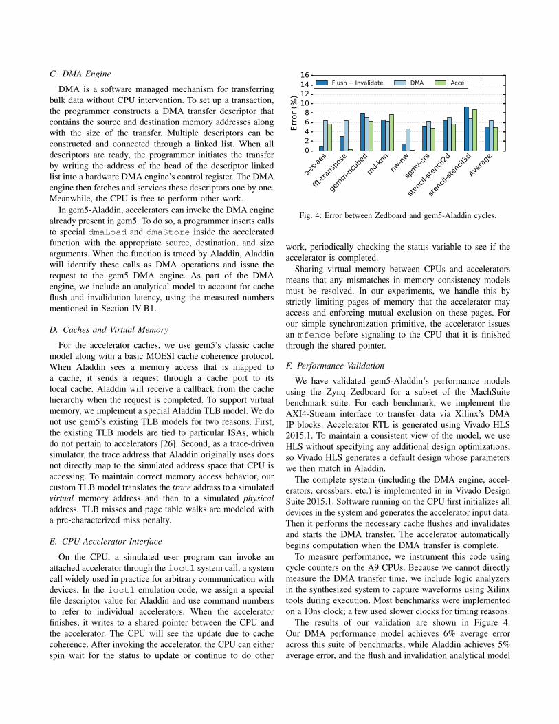
Fig. 4: Error between Zedboard and gem5-Aladdin cycles.
work, periodically checking the status variable to see if theaccelerator is completed.
Sharing virtual memory between CPUs and acceleratorsmeans that any mismatches in memory consistency modelsmust be resolved. In our experiments, we handle this bystrictly limiting pages of memory that the accelerator mayaccess and enforcing mutual exclusion on these pages. Forour simple synchronization primitive, the accelerator issuesan mfence before signaling to the CPU that it is finishedthrough the shared pointer.
F. Performance Validation
We have validated gem5-Aladdin’s performance modelsusing the Zynq Zedboard for a subset of the MachSuitebenchmark suite. For each benchmark, we implement theAXI4-Stream interface to transfer data via Xilinx’s DMAIP blocks. Accelerator RTL is generated using Vivado HLS2015.1. To maintain a consistent view of the model, we useHLS without specifying any additional design optimizations,so Vivado HLS generates a default design whose parameterswe then match in Aladdin.
The complete system (including the DMA engine, accel-erators, crossbars, etc.) is implemented in in Vivado DesignSuite 2015.1. Software running on the CPU first initializes alldevices in the system and generates the accelerator input data.Then it performs the necessary cache flushes and invalidatesand starts the DMA transfer. The accelerator automaticallybegins computation when the DMA transfer is complete.
To measure performance, we instrument this code usingcycle counters on the A9 CPUs. Because we cannot directlymeasure the DMA transfer time, we include logic analyzersin the synthesized system to capture waveforms using Xilinxtools during execution. Most benchmarks were implementedon a 10ns clock; a few used slower clocks for timing reasons.
The results of our validation are shown in Figure 4.Our DMA performance model achieves 6% average erroracross this suite of benchmarks, while Aladdin achieves 5%average error, and the flush and invalidation analytical model

achieves 5% average error. These results demonstrate theability of gem5-Aladdin to model a wide range of acceleratorworkloads accurately for both the accelerated kernels andimportant system-level considerations.
1) Validation omissions: Our validation focuses on thefeatures required by our DMA techniques: cache flushes andinvalidates, DMA transfer time, and accelerator runtime. Ingeneral, we validated as much of the new additions as wecould. Below are the components this work does not validateand our reasons for omitting them.
• CPU performance models: Existing work by Gutierrezet al. has already produced an accurate gem5 CPUmodel for the ARM A9 core[27], and gem5-Aladdinuses that validated model.
• Power model: All power results represent only theaccelerator power. We do not account for CPU power inany of our results. We use the same validated Aladdin’spower models with TSMC 40nm technology.
• Cache: To the best of our knowledge, there is no existingIP block available on Zynq such that we could imple-ment a cache controller on the programmable fabric.Furthermore, we never modified gem5’s cache models.
IV. MEMORY SYSTEM OPPORTUNITIES
In this section, we will discuss the primary design con-siderations when deciding whether to use a DMA- or cache-based memory system for an accelerator. Because baselineDMA leaves much room for improvement, we will also applytwo optimizations to DMA. We will then describe designconsiderations specific to cache-based accelerators. Finally,we will evaluate the performance of both memory systemsfor a set of representative benchmarks.
A. Primary design considerationsFirst, we compare and contrast DMA and caches across the
three system-level considerations mentioned earlier: push vs.pull, data movement granularity, management of coherency,and behavior under shared resource contention.
Push vs. Pull: DMA is designed for efficient bulkdata transfer where the data requirements of the programare well known a priori. This works well for streamingapplications and applications with high compute-to-memoryratios. However, applications with more irregular memoryaccess patterns, such as indirect memory accesses, can sufferwithout an on-demand memory system like a cache. Inaddition, because caches have the feature of automatic cacheline replacement, a cache can often afford to be smaller thana scratchpad that must hold all the data.
Data Movement Granularity: Because DMA is softwarecontrolled, the overheads of setting up a transaction are usu-ally amortized over a large bulk transfer. In contrast, cachespull in data at cache line granularity, enabling fine-grainedoverlap between compute and data movement. Although fine-grained DMA is possible, each new transactions adds addi-tional overheads. On the other hand, caches must perform tag
comparisons, replacements, and address translations, whichmake them inefficient for bulk data movement.
Cache Coherence Management: DMA engines typicallycan only access main memory or last level cache. There-fore, the programmer must conservatively flush any datathe accelerator may read out of private caches. Figure 2bshows that on average, accelerators employing traditionalDMA spend 20% of their total cycles on cache flushes.The flush is typically performed by software because DMAengines rarely participate in coherency (although there havebeen exceptions, like IBM Cell [28]). In contrast, hardware-managed caches handle all of this complexity transparentlyat the cost of additional hardware.
Shared Resource Contention: In a real scenario whereresources like the main system interconnect and main mem-ory are shared across multiple agents, invariably a DMAoperation or cache fill will stall to allow another processto make progress. A coarse-grained mechanism like DMAwill be affected much more by shared resource contentionbecause the accelerator usually waits for the entire transferto complete. In comparison, fine-grained memory accesseslike cache fills are less likely to contend due to their smallersize, and hit-under-miss allows other independent operationsto proceed even while an earlier cache load or store missed.
B. DMA Optimizations
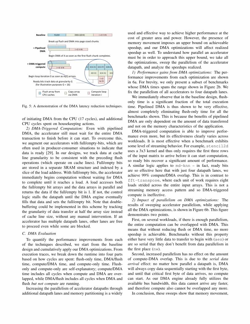
In this section, we improve the baseline DMA method byoverlapping various stages of the process. We will examinetwo DMA latency optimizations: pipelined DMA and DMA-triggered computation, which are depicted in Figure 5.
1) Pipelined DMA: Pipelined DMA reduces latency bydividing the flush and DMA operations into page sized blocksand overlapping the DMA of block b with the flush ofblock b + 1. We choose page size granularity to optimizefor DRAM row buffer hits. In the best case, we can hide allbut 4KB of the flush latency. Note that the correctness ofthis optimization is ensured by never starting a DMA blockbefore its flush has completed.
Cache line flush latency varies across ISAs and implemen-tations. For example, we characterized the flush throughputon the Zedboard’s Cortex A9 CPU to be one cache line per 56cycles at 667MHz. To achieve optimal pipelining and avoidbubbles, we want to match the flush and DMA latencies of a4KB transaction. On the Zedboard, this is achieved with anaccelerator clock frequency of 100MHz, which is why weuse this frequency for the rest of our experiments.
Breaking up a large flush and DMA operation introducesadditional overheads. The DMA engine must fetch newmetadata from main memory for every block, and the CPUmust synchronize flushes with dependent DMA operations.For this, we add a fixed 40 cycle delay to every DMAtransaction, also based on characterization. At 100MHz, thisaccounts for metadata reads (4 cycles), the one-way latency
i = 16 to 31
A[32:
A[48:63
FLUSH DMA A[0:N] i = 0 N
i = 0 N
15]
A[0:15]
A[16:31]
i = 0 to 15
Begin DMA of A as soon as the first flush chunk completes.
Baseline
+ Pipelined DMA
Break up flush and DMA into page sized chunks
i = 0 N
+ DMA-triggered compute
Begin loop iteration 0 as soon as A[0] arrives.
A[32:47]
A[16:31]
Ready bits track data at granularity G (for illustration purposes G = 16)
Copy array via DMA
Flush array from CPU caches
Compute loop iteration i
Fig. 5: A demonstration of the DMA latency reduction techniques.
of initiating DMA from the CPU (17 cycles), and additionalCPU cycles spent on housekeeping actions.
2) DMA-Triggered Computation: Even with pipelinedDMA, the accelerator still must wait for the entire DMAtransaction to finish before it can start. To overcome this,we augment our accelerators with full/empty-bits, which areoften used in producer-consumer situations to indicate thatdata is ready [29]. In our designs, we track data at cacheline granularity to be consistent with the preceding flushoperations (which operate on cache lines). Full/empty bitsare stored in a separate SRAM structure and indexed by aslice of the load address. With full/empty bits, the acceleratorimmediately begins computation without waiting for DMAto complete until it reaches a load. A load accesses boththe full/empty bit arrays and the data arrays in parallel andreturns the data if the full/empty bit is 1. If not, the controllogic stalls the datapath until the DMA engine eventuallyfills that data and sets the full/empty bit. Note that double-buffering could be implemented in this scheme by trackingthe granularity of data transfer at half the array size insteadof cache line size, without any manual intervention. If anaccelerator has multiple datapath lanes, other lanes are freeto proceed even while some are blocked.
C. DMA Evaluation
To quantify the performance improvements from eachof the techniques described, we start from the baselinedesign and cumulatively apply our DMA optimizations. Fromexecution traces, we break down the runtime into four partsbased on how cycles are spent: flush-only time, DMA/flushtime, compute/DMA time, and compute-only time. Flush-only and compute-only are self-explanatory; compute/DMAtime includes all cycles when compute and DMA are over-lapped, while DMA/flush includes all cycles when DMA andflush but not compute are running.
Increasing the parallelism of accelerator datapaths throughadditional datapath lanes and memory partitioning is a widely
used and effective way to achieve higher performance at thecost of greater area and power. However, the presence ofmemory movement imposes an upper bound on achieveablespeedup, and our DMA optimizations will affect realizedspeedup as well. To understand how parallel an acceleratormust be in order to approach this upper bound, we take allthe optimizations, sweep the parallelism of the acceleratordatapath, and analyze the speedups realized.
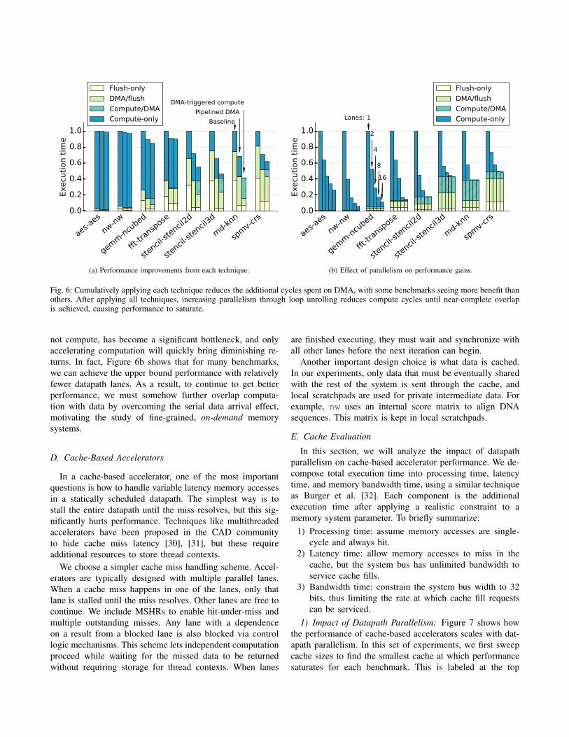
1) Performance gains from DMA optimizations: The per-formance improvements from each optimization are shownin 6a. For brevity, we only present a subset of benchmarkswhose DMA times spans the range shown in Figure 2b. Wefix the parallelism of all accelerators to four datapath lanes.
We immediately observe that in the baseline design, flush-only time is a significant fraction of the total executiontime. Pipelined DMA is thus shown to be very effective,almost completely eliminating flush-only time for all thebenchmarks shown. This is because the benefits of pipelinedDMA are only dependent on the amount of data transferredand not on the memory characteristics of the application.
DMA-triggered computation is able to improve perfor-mance even more, but its effectiveness clearly varies acrossworkloads. It is most effective when a benchmark exhibitssome level of streaming behavior. For example, stencil2duses a 3x3 kernel and thus only requires the first three rowsof the input matrix to arrive before it can start computation,so ready bits recover a significant amount of performance.A similar logic applies to md-knn – in fact, ready bitsare so effective here that with just four datapath lanes, weachieve 99% compute/DMA overlap. This is in contrast tofft-transpose, where each unit of work requires eightloads strided across the entire input arrays. This is not astreaming memory access pattern and so DMA-triggeredcompute is ineffective.
2) Impact of parallelism on DMA optimizations: Theresults of sweeping accelerator parallelism, while applyingall the DMA optimizations, is shown in Figure 6b. This figuredemonstrates two points.
First, on several workloads, if there is enough parallelism,the entire computation can be overlapped with DMA. Thismeans that without reducing flush or DMA time, no morespeedup is achievable. Benchmarks without this propertyeither have very little data to transfer to begin with (aes) orare so serial that they don’t benefit from data parallelism inthe first place (nw).
Second, increased parallelism has no effect on the amountof compute-DMA overlap. This is due to the serial dataarrival effect: no matter how parallel a datapath is, DMAwill always copy data sequentially starting with the first byte,and until that critical first byte of data arrives, no computecan start. As our DMA engine already fully utilizes theavailable bus bandwidth, this data cannot arrive any faster,and therefore compute also cannot be overlapped any more.
In conclusion, these sweeps show that memory movement,
aes-a
es
nw-nw
gemm
-ncu
bed
fft-tr
ansp
ose
sten
cil-st
encil
2d
sten
cil-st
encil
3d
md-k
nn
spm
v-cr
s0.0
0.2
0.4
0.6
0.8
1.0
Execu
tion t
ime
Baseline
Pipelined DMA
DMA-triggered compute
Flush-only
DMA/flush
Compute/DMA
Compute-only
(a) Performance improvements from each technique.
aes-a
es
nw-nw
gemm
-ncu
bed
fft-tr
ansp
ose
sten
cil-st
encil
2d
sten
cil-st
encil
3d
md-k
nn
spm
v-cr
s0.0
0.2
0.4
0.6
0.8
1.0
Execu
tion t
ime
1
2
4
8
16
Lanes:
Flush-only
DMA/flush
Compute/DMA
Compute-only
(b) Effect of parallelism on performance gains.
Fig. 6: Cumulatively applying each technique reduces the additional cycles spent on DMA, with some benchmarks seeing more benefit thanothers. After applying all techniques, increasing parallelism through loop unrolling reduces compute cycles until near-complete overlapis achieved, causing performance to saturate.
not compute, has become a significant bottleneck, and onlyaccelerating computation will quickly bring diminishing re-turns. In fact, Figure 6b shows that for many benchmarks,we can achieve the upper bound performance with relativelyfewer datapath lanes. As a result, to continue to get betterperformance, we must somehow further overlap computa-tion with data by overcoming the serial data arrival effect,motivating the study of fine-grained, on-demand memorysystems.
D. Cache-Based Accelerators
In a cache-based accelerator, one of the most importantquestions is how to handle variable latency memory accessesin a statically scheduled datapath. The simplest way is tostall the entire datapath until the miss resolves, but this sig-nificantly hurts performance. Techniques like multithreadedaccelerators have been proposed in the CAD communityto hide cache miss latency [30], [31], but these requireadditional resources to store thread contexts.
We choose a simpler cache miss handling scheme. Accel-erators are typically designed with multiple parallel lanes.When a cache miss happens in one of the lanes, only thatlane is stalled until the miss resolves. Other lanes are free tocontinue. We include MSHRs to enable hit-under-miss andmultiple outstanding misses. Any lane with a dependenceon a result from a blocked lane is also blocked via controllogic mechanisms. This scheme lets independent computationproceed while waiting for the missed data to be returnedwithout requiring storage for thread contexts. When lanes
are finished executing, they must wait and synchronize withall other lanes before the next iteration can begin.
Another important design choice is what data is cached.In our experiments, only data that must be eventually sharedwith the rest of the system is sent through the cache, andlocal scratchpads are used for private intermediate data. Forexample, nw uses an internal score matrix to align DNAsequences. This matrix is kept in local scratchpads.
E. Cache Evaluation
In this section, we will analyze the impact of datapathparallelism on cache-based accelerator performance. We de-compose total execution time into processing time, latencytime, and memory bandwidth time, using a similar techniqueas Burger et al. [32]. Each component is the additionalexecution time after applying a realistic constraint to amemory system parameter. To briefly summarize:
1) Processing time: assume memory accesses are single-cycle and always hit.
2) Latency time: allow memory accesses to miss in thecache, but the system bus has unlimited bandwidth toservice cache fills.
3) Bandwidth time: constrain the system bus width to 32bits, thus limiting the rate at which cache fill requestscan be serviced.
1) Impact of Datapath Parallelism: Figure 7 shows howthe performance of cache-based accelerators scales with dat-apath parallelism. In this set of experiments, we first sweepcache sizes to find the smallest cache at which performancesaturates for each benchmark. This is labeled at the top
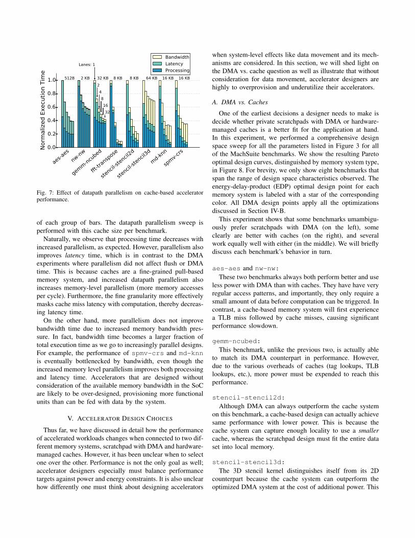
aes-a
es
nw-nw
gemm
-ncu
bed
fft-tr
ansp
ose
sten
cil-st
encil
2d
sten
cil-st
encil
3d
md-k
nn
spm
v-cr
s0.0
0.2
0.4
0.6
0.8
1.0
Norm
aliz
ed E
xecu
tion T
ime
512B 2 KB 32 KB 8 KB 8 KB 64 KB 16 KB 16 KB
Lanes: 1
2
4
8
16
32
Bandwidth
Latency
Processing
Fig. 7: Effect of datapath parallelism on cache-based acceleratorperformance.
of each group of bars. The datapath parallelism sweep isperformed with this cache size per benchmark.
Naturally, we observe that processing time decreases withincreased parallelism, as expected. However, parallelism alsoimproves latency time, which is in contrast to the DMAexperiments where parallelism did not affect flush or DMAtime. This is because caches are a fine-grained pull-basedmemory system, and increased datapath parallelism alsoincreases memory-level parallelism (more memory accessesper cycle). Furthermore, the fine granularity more effectivelymasks cache miss latency with computation, thereby decreas-ing latency time.
On the other hand, more parallelism does not improvebandwidth time due to increased memory bandwidth pres-sure. In fact, bandwidth time becomes a larger fraction oftotal execution time as we go to increasingly parallel designs.For example, the performance of spmv-crs and md-knnis eventually bottlenecked by bandwidth, even though theincreased memory level parallelism improves both processingand latency time. Accelerators that are designed withoutconsideration of the available memory bandwidth in the SoCare likely to be over-designed, provisioning more functionalunits than can be fed with data by the system.
V. ACCELERATOR DESIGN CHOICES
Thus far, we have discussed in detail how the performanceof accelerated workloads changes when connected to two dif-ferent memory systems, scratchpad with DMA and hardware-managed caches. However, it has been unclear when to selectone over the other. Performance is not the only goal as well;accelerator designers especially must balance performancetargets against power and energy constraints. It is also unclearhow differently one must think about designing accelerators
when system-level effects like data movement and its mech-anisms are considered. In this section, we will shed light onthe DMA vs. cache question as well as illustrate that withoutconsideration for data movement, accelerator designers arehighly to overprovision and underutilize their accelerators.
A. DMA vs. Caches
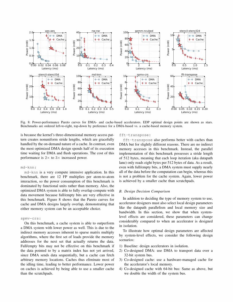
One of the earliest decisions a designer needs to make isdecide whether private scratchpads with DMA or hardware-managed caches is a better fit for the application at hand.In this experiment, we performed a comprehensive designspace sweep for all the parameters listed in Figure 3 for allof the MachSuite benchmarks. We show the resulting Paretooptimal design curves, distinguished by memory system type,in Figure 8. For brevity, we only show eight benchmarks thatspan the range of design space characteristics observed. Theenergy-delay-product (EDP) optimal design point for eachmemory system is labeled with a star of the correspondingcolor. All DMA design points apply all the optimizationsdiscussed in Section IV-B.
This experiment shows that some benchmarks umambigu-ously prefer scratchpads with DMA (on the left), someclearly are better with caches (on the right), and severalwork equally well with either (in the middle). We will brieflydiscuss each benchmark’s behavior in turn.
aes-aes and nw-nw:These two benchmarks always both perform better and use
less power with DMA than with caches. They have have veryregular access patterns, and importantly, they only require asmall amount of data before computation can be triggered. Incontrast, a cache-based memory system will first experiencea TLB miss followed by cache misses, causing significantperformance slowdown.
gemm-ncubed:This benchmark, unlike the previous two, is actually able
to match its DMA counterpart in performance. However,due to the various overheads of caches (tag lookups, TLBlookups, etc.), more power must be expended to reach thisperformance.
stencil-stencil2d:Although DMA can always outperform the cache system
on this benchmark, a cache-based design can actually achievesame performance with lower power. This is because thecache system can capture enough locality to use a smallercache, whereas the scratchpad design must fit the entire dataset into local memory.
stencil-stencil3d:The 3D stencil kernel distinguishes itself from its 2D
counterpart because the cache system can outperform theoptimized DMA system at the cost of additional power. This
0.00 0.02 0.04 0.06 0.08Latency (ms)
0.0
0.5
1.0
1.5
2.0
Pow
er
(mW
)
aes-aes
DMA
Cache
0.0 0.1 0.2 0.3 0.4Latency (ms)
0
10
20
30
40
Pow
er
(mW
)
nw-nw
DMA
Cache
0 2 4 6Latency (ms)
0
20
40
60
80
100
Pow
er
(mW
)
gemm-ncubed
DMA
Cache
0.0 0.5 1.0 1.5Latency (ms)
0
5
10
Pow
er
(mW
)
stencil-stencil2d
DMA
Cache
0.0 0.2 0.4 0.6 0.8 1.0Latency (ms)
0
10
20
30
Pow
er
(mW
)
stencil-stencil3d
DMA
Cache
0.0 0.1 0.2 0.3 0.4 0.5Latency (ms)
0
20
40
60
80
100Pow
er
(mW
)md-knn
DMA
Cache
0.0 0.1 0.2 0.3Latency (ms)
0
2
4
6
8
10
Pow
er
(mW
)
spmv-crs
DMA
Cache
0.00 0.05 0.10 0.15 0.20Latency (ms)
0
20
40
60
Pow
er
(mW
)
fft-transpose
DMA
Cache
Fig. 8: Power-performance Pareto curves for DMA- and cache-based accelerators. EDP optimal design points are shown as stars.Benchmarks are ordered left-to-right, top-down by preference for a DMA-based vs. a cache-based memory system.
is because the kernel’s three-dimensional memory access pat-tern creates nonuniform stride lengths, which are gracefullyhandled by the on-demand nature of a cache. In contrast, eventhe most optimized DMA design spends half of its executiontime waiting for DMA and flush operations. The cost of thisperformance is 2× to 3× increased power.
md-knn:md-knn is a very compute intensive application. In this
benchmark, there are 12 FP multiplies per atom-to-atominteraction, so the power consumption of this benchmark isdominated by functional units rather than memory. Also, theoptimized DMA system is able to fully overlap compute withdata movement because full/empty bits are very effective inthis benchmark. Figure 8 shows that the Pareto curves forcache and DMA designs largely overlap, demonstrating thateither memory system can be an acceptable choice.
spmv-crs:On this benchmark, a cache system is able to outperform
a DMA system with lower power as well. This is due to theindirect memory accesses inherent to sparse matrix multiplyalgorithms, where the first set of loads provide the memoryaddresses for the next set that actually returns the data.Full/empty bits may not be effective on this benchmark ifthe data pointed to by a matrix index has not yet arrived,since DMA sends data sequentially, but a cache can fetcharbitrary memory locations. Caches thus eliminate most ofthe idling time, leading to better performance. Lower poweron caches is achieved by being able to use a smaller cachethan the scratchpads.
fft-transpose:fft-transpose also performs better with caches than
DMA but for slightly different reasons. There are no indirectmemory accesses in this benchmark. Instead, the parallelimplementation of this benchmark possesses a stride lengthof 512 bytes, meaning that each loop iteration (aka datapathlane) only reads eight bytes per 512 bytes of data. As a result,even with full/empty bits, a DMA system must supply nearlyall of the data before the computation can begin, whereas thisis not a problem for the cache system. Again, lower poweris achieved by a smaller cache than scratchpads.
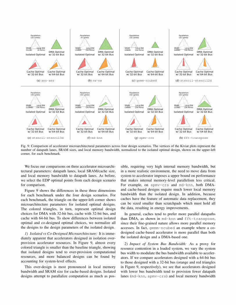
B. Design Decision Comparison
In addition to deciding the type of memory system to use,accelerator designers must also select local design parameterslike the datapath parallelism and local memory size andbandwidth. In this section, we show that when system-level effects are considered, these parameters can changeconsiderably compared to when an accelerator is designedin isolation.
To illustrate how optimal design parameters are affectedby system-level effects, we consider the following designscenarios:
1) Baseline: design accelerators in isolation.2) Co-designed DMA: use DMA to transport data over a
32-bit system bus.3) Co-designed cache: use a hardware-managed cache for
the accelerator’s local memory.4) Co-designed cache with 64-bit bus: Same as above, but
we double the width of the system bus.
Parallelism(32 Lanes)
SRAM(512B)
Local BW(4 Ports)
Isolated OptimalDMA Optimalw/ 32-bit Bus
Cache Optimalw/ 32-bit Bus
Cache Optimalw/ 64-bit Bus
(a) aes-aes
Parallelism(4 Lanes)
SRAM(34KB)
Local BW(16 Ports)
Isolated OptimalDMA Optimalw/ 32-bit Bus
Cache Optimalw/ 32-bit Bus
Cache Optimalw/ 64-bit Bus
(b) nw-nw
Parallelism(32 Lanes)
SRAM(49KB)
Local BW(16 Ports)
Isolated OptimalDMA Optimalw/ 32-bit Bus
Cache Optimalw/ 32-bit Bus
Cache Optimalw/ 64-bit Bus
(c) gemm-ncubed
Parallelism(32 Lanes)
SRAM(64KB)
Local BW(16 Ports)
Isolated OptimalDMA Optimalw/ 32-bit Bus
Cache Optimalw/ 32-bit Bus
Cache Optimalw/ 64-bit Bus
(d) stencil-stencil2d
Parallelism(16 Lanes)
SRAM(128KB)
Local BW(16 Ports)
Isolated OptimalDMA Optimalw/ 32-bit Bus
Cache Optimalw/ 32-bit Bus
Cache Optimalw/ 64-bit Bus
(e) stencil-stencil3d
Parallelism(32 Lanes)
SRAM(45KB)
Local BW(16 Ports)
Isolated OptimalDMA Optimalw/ 32-bit Bus
Cache Optimalw/ 32-bit Bus
Cache Optimalw/ 64-bit Bus
(f) md-knn
Parallelism(32 Lanes)
SRAM(30KB)
Local BW(16 Ports)
Isolated OptimalDMA Optimalw/ 32-bit Bus
Cache Optimalw/ 32-bit Bus
Cache Optimalw/ 64-bit Bus
(g) spmv-crs
Parallelism(32 Lanes)
SRAM(21KB)
Local BW(16 Ports)
Isolated OptimalDMA Optimalw/ 32-bit Bus
Cache Optimalw/ 32-bit Bus
Cache Optimalw/ 64-bit Bus
(h) fft-transpose
Fig. 9: Comparison of accelerator microarchitectural parameters across four design scenarios. The vertices of the Kiviat plots represent thenumber of datapath lanes, SRAM sizes, and local memory bandwidth, normalized to the isolated optimal design, shown on the upper-leftcorner, for each benchmark.
We focus our comparisons on three accelerator microarchi-tectural parameters: datapath lanes, local SRAM/cache size,and local memory bandwidth to datapath lanes. As before,we select the EDP optimal points from each design scenariofor comparison.
Figure 9 shows the differences in these three dimensionsfor each benchmark under the four design scenarios. Foreach benchmark, the triangle on the upper-left corner showsmicroarchitecture parameters for isolated optimal designs.The colored triangles, in turn, represent optimal designchoices for DMA with 32-bit bus, cache with 32-bit bus, andcache with 64-bit bus. To show differences between isolatedoptimal and co-designed optimal choices, we normalize allthe designs to the design parameters of the isolated design.
1) Isolated vs Co-Designed Microarchitecture: It is imme-diately apparent that accelerators designed in isolation over-provision accelerator resources. In Figure 9, almost everycolored triangle is smaller than the baseline triangle, showingthat isolated designs tend to over-provision computationalresources, and more balanced designs can be found byaccounting for system-level effects.
This over-design is most pronounced in local memorybandwidth and SRAM size for cache-based designs. Isolateddesigns attempt to parallalize computation as much as pos-
sible, requiring very high internal memory bandwidth, butin a more realistic environment, the need to move data fromsystem to accelerator imposes a upper bound on performancethat makes internal memory-level parallelism less critical.For example, on spmv-crs and md-knn, both DMA-and cache-based designs require much lower local memorybandwidth than the isolated design. In addition, becausecaches have the feature of automatic data replacement, theycan be sized smaller than scratchpads which must hold allthe data, resulting in energy improvements.
In general, caches tend to prefer more parallel datapathsthan DMA, as shown in md-knn and fft-transpose,since their fine-grained nature allows more parallel memoryaccesses. In fact, gemm-ncubed an example where a co-designed cache-based accelerator is more parallel than boththe isolated design and a DMA-based one.
2) Impact of System Bus Bandwidth: As a proxy forresource contention in a loaded system, we vary the systembus width to modulate the bus bandwidth available to acceler-ators. If we compare accelerators designed with a 64-bit busto those designed with a 32-bit bus (orange and red trianglesin Figure 9, respectively), we see that accelerators designedwith lower bus bandwidth tend to provision fewer datapathlanes (md-knn, spmv-crs) and local memory bandwidth
aes-a
es
nw-nw
gemm
-ncu
bed
sten
cil2d
sten
cil3d
md-k
nn
spm
v-cr
s
fft-tr
ansp
ose
Geom
ean
0
1
2
3
4
5
6
7
8
ED
P Im
pro
vem
ent
(X) DMA w/ 32bit bus
Cache w/ 32bit bus
Cache w/ 64bit bus
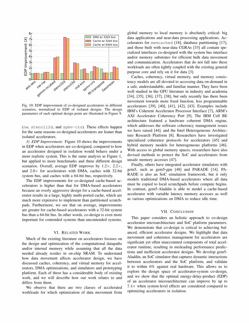
Fig. 10: EDP improvement of co-designed accelerators in differentscenarios, normalized to EDP of isolated designs. The designparameters of each optimal design point are illustrated in Figure 9.
(nw, stencil2d, and spmv-crs). These effects happenfor the same reasons co-designed accelerators are leaner thanisolated accelerators.
3) EDP Improvement: Figure 10 shows the improvementsin EDP when accelerators are co-designed, compared to howan accelerator designed in isolation would behave under amore realistic system. This is the same analysis as Figure 1,but applied to more benchmarks and three different designscenarios. Overall, average EDP improves by 1.2×, 2.2×,and 2.0× for accelerators with DMA, caches with 32-bitsystem bus, and caches with a 64-bit bus, respectively.
The EDP improvements for co-designed cache-based ac-celerators is higher than that for DMA-based acceleratorsbecause an overly aggressive design for a cache-based accel-erator results in a large, highly multi-ported cache, which aremuch more expensive to implement than partitioned scratch-pads. Furthermore, we see that on average, improvementsare greater for cache-based accelerators with a 32-bit systembus than a 64-bit bus. In other words, co-design is even moreimportant for contended systems than uncontended systems.
VI. RELATED WORK
Much of the existing literature on accelerators focuses onthe design and optimization of the computational datapathsand/or internal memory while assuming that all the dataneeded already resides in on-chip SRAM. To understandhow data movement affects accelerator design, we havediscussed caches, coherency, and virtual memory for accel-erators, DMA optimizations, and simulators and prototypingplatform. Each of these has a considerable body of existingwork, and we will describe how our work relates to anddiffers from them.
We observe that there are two classes of acceleratedworkloads for which optimization of data movement from
global memory to local memory is absolutely critical: bigdata applications and near-data processing applications. Ac-celerators for memcached [18], database partitioning [17],and those built with near-data CGRAs [33] all contain spe-cialized interfaces co-designed with the system bus interfaceand/or memory substrates for efficient bulk data movementand communication. Accelerators that do not fall into theseworkloads are often tightly coupled with the existing generalpurpose core and rely on it for data [3].
Caches, coherency, virtual memory, and memory consis-tency models are all devoted to accessing data on-demand ina safe, understandable, and familiar manner. They have beenwell studied in the GPU literature in industry and academia[34], [35], [36], [37], [38], but only recently has there beenmovement towards more fixed function, less programmableaccelerators [39], [40], [41], [42], [43]. Examples includeIBM’s Coherent Accelerator Processor Interface [7], ARM’sAXI Accelerator Coherency Port [9], The IBM Cell BEarchitecture featured a hardware coherent DMA engine,which addresses the software coherency management issueswe have raised [44]. and the Intel Heterogeneous Architec-ture Research Platform [8]. Researchers have investigatedspecialized coherence protocols for accelerators [45] andhybrid memory models for heterogeneous platforms [46].With access to global memory spaces, researchers have alsodevised methods to protect the SoC and accelerators fromunsafe memory accesses [47].
Finally, others have integrated accelerator simulators withgem5, such as gem5-gpu [48] and PARADE [14]. PA-RADE is also an SoC simulation framework, but it onlymodels traditional DMA-based accelerators where all datamust be copied to local scratchpads before compute begins.In contrast, gem5-Aladdin is able to model a cache-basedaccelerator with variable latency memory accesses as wellas various optimizations on DMA to reduce idle time.
VII. CONCLUSION
This paper considers an holistic approach to co-designaccelerator microarchitecture and SoC platform parameters.We demonstrate that co-design is critical to achieving bal-anced, efficient accelerator designs. We highlight that datamovement and coherence management for accelerators aresignificant yet often unaccounted components of total accel-erator runtime, resulting in misleading performance predic-tions and inefficient accelerator designs. We develop gem5-Aladdin, an SoC simulator that captures dynamic interactionsbetween accelerators and the SoC platform, and validateit to within 6% against real hardware. This allows us toexplore the design space of accelerator-system co-design,and we show that the optimal energy-delay-product (EDP)of an accelerator microarchitecture can improve by up to7.4× when system-level effects are considered compared tooptimizing accelerators in isolation.
VIII. ACKNOWLEDGMENTS
This work was partially supported by C-FAR, one of six centersof STARnet, a Semiconductor Research Corporation program spon-sored by MARCO and DARPA. The work was also supported inpart by DARPA under Contract #: HR0011-13-C-0022. Y.S. Shaowas partially supported by an IBM Ph.D. Fellowship and a SiebelScholarship. S. Xi is partially supported by a National ScienceFoundation Graduate Fellowship. This research was, in part, fundedby the U.S. Government. The views and conclusions contained inthis document are those of the authors and should not be interpretedas representing the official policies, either expressed or implied, ofthe U.S. Government.
REFERENCES
[1] Y. S. Shao and D. Brooks, “Research Infrastructures for HardwareAccelerators,” Synthesis Lectures on Computer Architecture, 2015.
[2] Y.-H. Chen, T. Krishna, J. Emer, and V. Sze, “Eyeriss: An Energy-Efficient Reconfigurable Accelerator for Deep Convolutional NeuralNetworks,” in ISSCC, 2016.
[3] W. Qadeer, R. Hameed, O. Shacham, P. Venkatesan, C. Kozyrakis,and M. A. Horowitz, “Convolution engine: Balancing efficiency &flexibility in specialized computing,” in ISCA, 2013.
[4] T. Chen, Z. Du, N. Sun, J. Wang, C. Wu, Y. Chen, and O. Temam,“Diannao: A small-footprint high-throughput accelerator for ubiquitousmachine-learning,” in ASPLOS, 2014.
[5] B. Reagen, P. Whatmough, R. Adolf, S. Rama, H. Lee, S. K. Lee, J. M.Hernandez-Lobato, G.-Y. Wei, and D. Brooks, “Minerva: EnablingLow-Power, Highly-Accurate Deep Neural Network Accelerators,” inISCA, 2016.
[6] I. Magaki, M. Khazraee, L. V. Gutierrez, and M. B. Taylor, “ASICClouds: Specializing the Datacenter,” in ISCA, 2016.
[7] J. Stuecheli, “POWER8 Processor,” in HotChips, 2013.[8] D. Bryant, “Disrupting the Data Center to Create the Digital Services
Economy,” Intel Announcement, 2014.[9] S. Neuendorffer and F. Martinez-Vallina, “Building Zynq accelerators
with Vivado high level synthesis,” in FPGA, 2013.[10] N. L. Binkert, B. M. Beckmann, G. Black, S. K. Reinhardt, A. G.
Saidi, A. Basu, J. Hestness, D. Hower, T. Krishna, S. Sardashti, R. Sen,K. Sewell, M. Shoaib, N. Vaish, M. D. Hill, and D. A. Wood, “Thegem5 simulator,” SIGARCH Computer Architecture News, 2011.
[11] T. E. Carlson, W. Heirman, and L. Eeckhout, “Sniper: Exploring theLevel of Abstraction for Scalable and Accurate Parallel Multi-CoreSimulation,” in SC, 2011.
[12] S. Kanev, G.-Y. Wei, and D. Brooks, “XIOSim: Power-PerformanceModeling of Mobile x86 Cores,” in ISLPED, 2012.
[13] Y. S. Shao, B. Reagen, G.-Y. Wei, and D. Brooks, “Aladdin: APre-RTL, Power-Performance Accelerator Simulator Enabling LargeDesign Space Exploration of Customized Architectures,” in ISCA,2014.
[14] J. Cong, Z. Fang, M. Gill, and G. Reinman, “PARADE: A Cycle-Accurate Full-System Simulation Platform for Accelerator-Rich Ar-chitectural Design and Exploration,” in ICCAD, 2015.
[15] G. Venkatesh, J. Sampson, N. Goulding, S. Garcia, V. Bryksin,J. Lugo-Martinez, S. Swanson, and M. B. Taylor, “Conservation cores:reducing the energy of mature computations,” ASPLOS, 2010.
[16] E. S. Chung, P. A. Milder, J. C. Hoe, and K. Mai, “Single-ChipHeterogeneous Computing: Does the Future Include Custom Logic,FPGAs, and GPGPUs?,” in MICRO, 2010.
[17] L. Wu, R. J. Barker, M. A. Kim, and K. A. Ross, “Navigating Big Datawith High-Throughput, Energy-Efficient Data Partitioning,” in ISCA,2013.
[18] K. T. Lim, D. Meisner, A. G. Saidi, P. Ranganathan, and T. F. Wenisch,“Thin Servers with Smart Pipes: Designing SoC Accelerators forMemcached,” in ISCA, 2013.
[19] R. Hameed, W. Qadeer, M. Wachs, O. Azizi, A. Solomatnikov, B. C.Lee, S. Richardson, C. Kozyrakis, and M. Horowitz, “UnderstandingSources of Inefficiency in General-Purpose Chips,” in ISCA, 2010.
[20] H. Esmaeilzadeh, A. Sampson, L. Ceze, and D. Burger, “NeuralAcceleration for General-Purpose Approximate Programs,” in MICRO,2012.
[21] A. Krishna, T. Heil, N. Lindberg, F. Toussi, and S. VanderWiel,“Hardware Acceleration in the IBM PowerEN Processor: Architectureand Performance,” in PACT, 2012.
[22] “TI OMAP Applications Processors.”[23] B. Blaner, B. Abali, B. Bass, S. Chari, R. Kalla, S. Kunkel, K. Lauri-
cella, R. Leavens, J. Reilly, and P. Sandon, “IBM POWER7+ ProcessorOn-Chip Accelerators for Cryptography and Active Memory Expan-sion,” IBM Journal of Research and Development, 2013.
[24] P. Yedlapalli, N. C. Nachiappan, N. Soundararajan, A. Sivasubrama-niam, M. T. Kandemir, and C. R. Das, “Short-Circuiting MemoryTraffic in Handheld Platforms,” in MICRO, pp. 166–177, 2014.
[25] B. Reagen, R. Adolf, Y. S. Shao, G.-Y. Wei, and D. Brooks, “Mach-Suite: Benchmarks for Accelerator Design and Customized Architec-tures,” in IISWC, 2014.
[26] Y. S. Shao and D. Brooks, “ISA-Independent Workload Characteri-zation and its Implications for Specialized Architectures,” in ISPASS,2013.
[27] A. Gutierrez, J. Pusdesris, R. G. Dreslinski, T. Mudge, C. Sudanthi,C. D. Emmons, M. Hayenga, and N. Paver, “Sources of Error in Full-System Simulation,” in ISPASS, 2014.
[28] M. Kistler, M. Perrone, and F. Petrini, “Cell Multiprocessor Commu-nication Network: Built for Speed,” in IEEE Micro, 2006.
[29] D. Lustig and M. Martonosi, “Reducing GPU Offload Latency viaFine-Grained CPU-GPU Synchronization,” in HPCA, 2013.
[30] M. Tan, B. Liu, S. Dai, and Z. Zhang, “Multithreaded PipelineSynthesis for Data-Parallel Kernels,” in ICCAD, 2014.
[31] J. Huthmann, J. Oppermann, and A. Koch, “Automatic High-LevelSynthesis of Multi-Threaded Hardware Accelerators,” in FPL, 2014.
[32] D. Burger, J. R. Goodman, and A. Kagi, “Memory Bandwidth Limi-tations of Future Microprocessors,” in ISCA, 1996.
[33] A. Farmahini-Farahani, J. H. Ahn, K. Morrow, and N. S. Kim, “NDA:Near-DRAM acceleration architecture leveraging commodity DRAMdevices and standard memory modules,” in HPCA, 2015.
[34] M. Harris, “Unified Memory in CUDA 6,” 2013.[35] J. Power, A. Basu, J. Gu, S. Puthoor, B. M. Beckmann, M. D. Hill,
S. K. Reinhardt, and D. A. Wood, “Heterogeneous System Coherencefor Integrated CPU-GPU Systems,” in MICRO, 2013.
[36] J. Power, M. D. Hill, and D. A. Wood, “Supporting x86-64 addresstranslation for 100s of gpu lanes,” in HPCA, pp. 568–578, IEEE, 2014.
[37] B. Pichai, L. Hsu, and A. Bhattacharjee, “Architectural Support forAddress Translation on GPUs,” ASPLOS, 2014.
[38] R. Komuravelli, M. D. Sinclair, J. Alsop, M. Huzaifa, M. Kotsifakou,P. Srivastava, S. V. Adve, and V. S. Adve, “Stash: Have YourScratchpad and Cache It Too,” in ISCA, 2015.
[39] M. J. Lyons, M. Hempstead, G.-Y. Wei, and D. Brooks, “The Ac-celerator Store: A Shared Memory Framework for Accelerator-BasedSystems,” TACO, 2012.
[40] M. Lyons, G.-Y. Wei, and D. Brooks, “Multi-accelerator systemdevelopment with the shrinkfit acceleration framework,” in ICCD,2014.
[41] C. F. Fajardo, Z. Fang, R. Iyer, G. F. Garcia, S. E. Lee, andL. Zhao, “Buffer-integrated-cache: a cost-effective sram architecturefor handheld and embedded platforms,” in DAC, 2011.
[42] Y. S. Shao, S. Xi, V. Srinivasan, G.-Y. Wei, and D. Brooks, “TowardCache-Friendly Hardware Accelerators,” in Sensors and Cloud Archi-tectures Workshop (HPCA), 2015.
[43] T. J. Ham, J. L. Aragon, and M. Martonosi, “DeSC: Decoupled Supply-Compute Communication Management for Heterogeneous Architec-tures,” in MICRO, 2015.
[44] T. Chen, R. Raghavan, J. Dale, and E. Iwata, “Cell Broadband EngineArchitecture and its First Implementation - A Performance View,” inIBM Journal of Research and Development, 2007.
[45] S. Kumar, A. Shriraman, and N. Vedula, “Fusion: Design Tradeoffs inCoherent Cache Hierarchies for Accelerators,” in ISCA, 2015.
[46] J. H. Kelm, D. R. Johnson, W. Tuohy, S. S. Lumetta, and S. J. Patel,“Cohesion: a hybrid memory model for accelerators,” in ISCA, 2010.
[47] L. E. Olson, J. Power, M. D. Hill, and D. A. Wood, “Border Control:Sandboxing Accelerators,” in MICRO, 2015.
[48] J. Power, J. Hestness, M. Orr, M. Hill, and D. Wood, “gem5-gpu: AHeterogeneous CPU-GPU Simulator,” Computer Architecture Letters,2014.