Embed Size (px)
Citation preview

RTI International
CO2 Capture Membrane Process
for Power Plant Flue Gas
Lora Toy, Aqil Jamal, Atish Kataria, Ranjeeth Kalluri, and Raghubir Gupta
RTI International, Center for Energy Technology, Research Triangle Park, NC
Ramin Amin-Sanayei, Cedric Airaud, Caiping Lin, and John Schmidhauser
Arkema Inc., King of Prussia, PA
John Jensvold, Fred Coan, Raymond Chan, and Marc Straub
Generon IGS, Inc., Pittsburg, CA
2010 NETL CO2 Capture Technology Meeting
Pittsburgh, PA
September 14, 2010

RTI International
RTI InternationalCenter for Energy Technology (CET)
CET Program Areas
Advanced Gasification
– Warm syngas cleanup/conditioning
– Substitute natural gas (SNG) production
– Hydrogen production (Iron-steam process)
Clean Fuels
– Syngas to fuels and chemicals
– Hydrocarbon desulfurization
CO2 Capture and Reuse
– Pre- and post-combustion CO2 capture
– Membrane separation
– CO2 reuse
Biomass Conversion and Biofuels
– Biomass gasification; Syngas cleanup/conditioning
– Biomass pyrolysis
RTI International
Experienced staff
40 staff: 16 PhD, 6 MS
Chemical engineers
Chemists
Mechanical engineers
Support staff
Core Competencies
Sorbent, catalyst, and membrane development
Reaction engineering
Process design, modeling, development, and integration
Bench-scale and prototype testing
RTI International
Established in 1958
One of the world’s leading research institutes
>2,800 staff; >$717MM revenue (2009)
Mission: To improve the human condition by
turning knowledge into practice

RTI International
Project Overview
Project Team
RTI
Arkema Inc.
Generon IGS, Inc.
U.S. EPA / ARCADIS
University of North Carolina
at Chapel Hill [UNC-CH]
Cogeneration Facility
DOE/NETL Cooperative Agreement #DE-NT0005313
DOE Project Manager: José Figueroa
RTI Project Manager: Lora Toy
Period of Performance
October 1, 2008 – March 31, 2011
Funding
DOE Share: $1,944,821
Cost Share: $486,206
Total Funding: $2,431,027
Overall Project Objective
Develop an advanced polymeric membrane-based process that can be cost-effectively and reliably
retrofitted into existing pulverized coal plants to capture ≥ 90% CO2 from plant’s flue gas at 50-60 °C
with ≤ 35% Increase in Cost of Electricity (ICOE)

RTI International
Membrane Approach
DSP
Permeability Solubility Diffusivity
2
2
2
2
2
2
22
N
C
N
C
N
C
/NC
D
D
S
S
P
POOO
O
SelectivitySolubility
selectivity
Mobility
selectivity
Solution-diffusion mechanism
(i) Sorption on high-pressure side
(ii) Diffusion down partial pressure gradient
(iii) Desorption on low-pressure side
CO2
Membrane
Gas flux
High pressure Low pressure
p2
H O2
SO2
N 2
p1
CO2CO2
Membrane
Gas flux
High pressure Low pressure
p2
H O2
H O2
SO2
SO2
N 2N 2
p1 Advantages
Passive separation
– Inherently energy-efficient
– No heating needed to recover CO2
(unlike adsorption and absorption
processes)
Simple to operate and maintain
– No moving parts
Compact
Modular
– Easy scalability
– Easy to retrofit into existing process
infrastructures
No secondary hazardous waste stream
RTI International
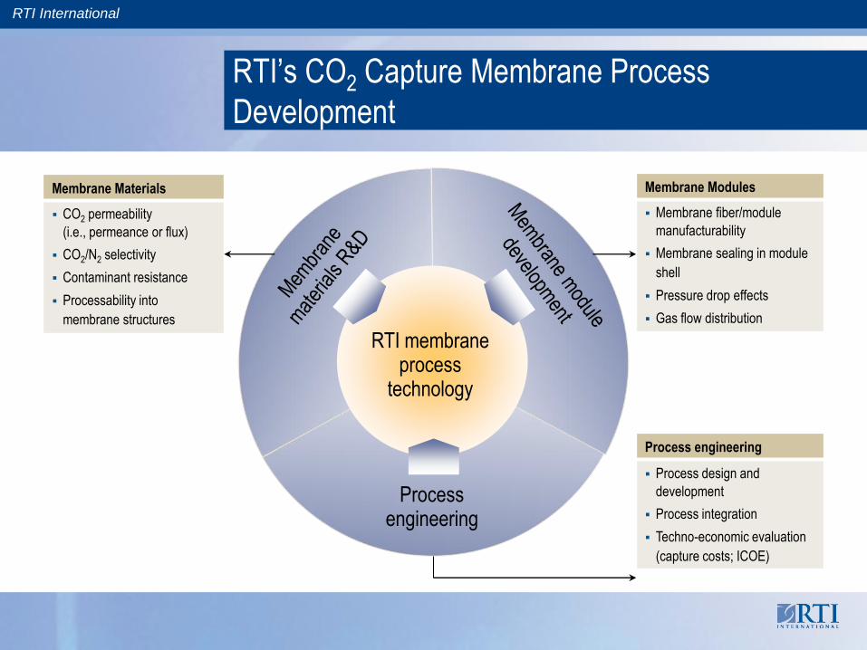
RTI membrane process
technology
RTI’s CO2 Capture Membrane Process
Development
Processengineering
Membrane Materials
CO2 permeability
(i.e., permeance or flux)
CO2/N2 selectivity
Contaminant resistance
Processability into
membrane structures
Membrane Modules
Membrane fiber/module
manufacturability
Membrane sealing in module
shell
Pressure drop effects
Gas flow distribution
Process engineering
Process design and
development
Process integration
Techno-economic evaluation
(capture costs; ICOE)

RTI International
Example Membrane Module Cost Comparison(550-MWe coal plant; 90% capture; 95% CO2 purity; CO2/N2 = 35; 1.3 × 10⁶ acfm)
a Assumed standard module size of 8 in. × 40 in. for spiral-wound and
6 in. × 36 in. for hollow-fiber.
b Cost for spiral-wound from Merkel et al. [J. Membr. Sci.,359, 126-139
(2010)] and for hollow-fiber from project partner Generon.
Hollow-Fiber Membrane Modules
for High-Volume Applications
End Plate
Epoxy Tube Sheet
Support Core
Feed Air O-Rings
Hollow Fibers
Oxygen-
Enriched Air
Epoxy Tube
Sheet
Enriched
Nitrogen
Product
Gas
End Plate
Epoxy Tube Sheet
Support Core
Feed Air O-Rings
Hollow Fibers
Oxygen-
Enriched Air
Epoxy Tube
Sheet
Enriched
Nitrogen
Product
GasGeneron
membrane
module
Common Membrane Module Designs
Used for Gas Separations
Ref. Baker, R. W., “Membrane Technology and Applications”, 2nd ed.,
John Wiley and Sons: West Sussex, England, 2004, pp. 89-160.
Hollow-fiber module type selected
– Lower module cost per membrane area
– Much higher membrane packing density
– More suitable and cost-effective for high-volume
applications (e.g., air separation)
For the same membrane permeance and selectivity,
the hollow-fiber design is much more cost-effective
than spiral-wound.
Characteristic Spiral-wound Hollow-fiber
Packing density (ft2/ft3) 300-1,000 3,000-5,000
Cost ($/ft2) 1-5 0.2-1
Area of std. module (ft2) 200-640 3,000-7,000
Spiral-wound Hollow-fiber
Membrane area2.6 107 ft2 (400 GPU)
1 107 ft2 (1,000 GPU)2.6 107 ft2 (400 GPU)
Area per modulea 1,163 ft2 2,200 ft2
No. of modules22,356 (400 GPU)
8,599 (1,000 GPU)11,819 (400 GPU)
Module cost (installed)b $4.65/ft2 $1.05/ft2
Total module cost$121MM (400 GPU)
$46.5 MM (1,000 GPU)$27.3MM (400 GPU)
RTI International
30
60
90
120
150
50 60 70 80 90 100
Inc
rea
se
in
CO
E (
%)
[rel. t
o b
ase
pla
nt
wit
ho
ut
ca
ptu
re]
CO2 purity of captured stream (%)
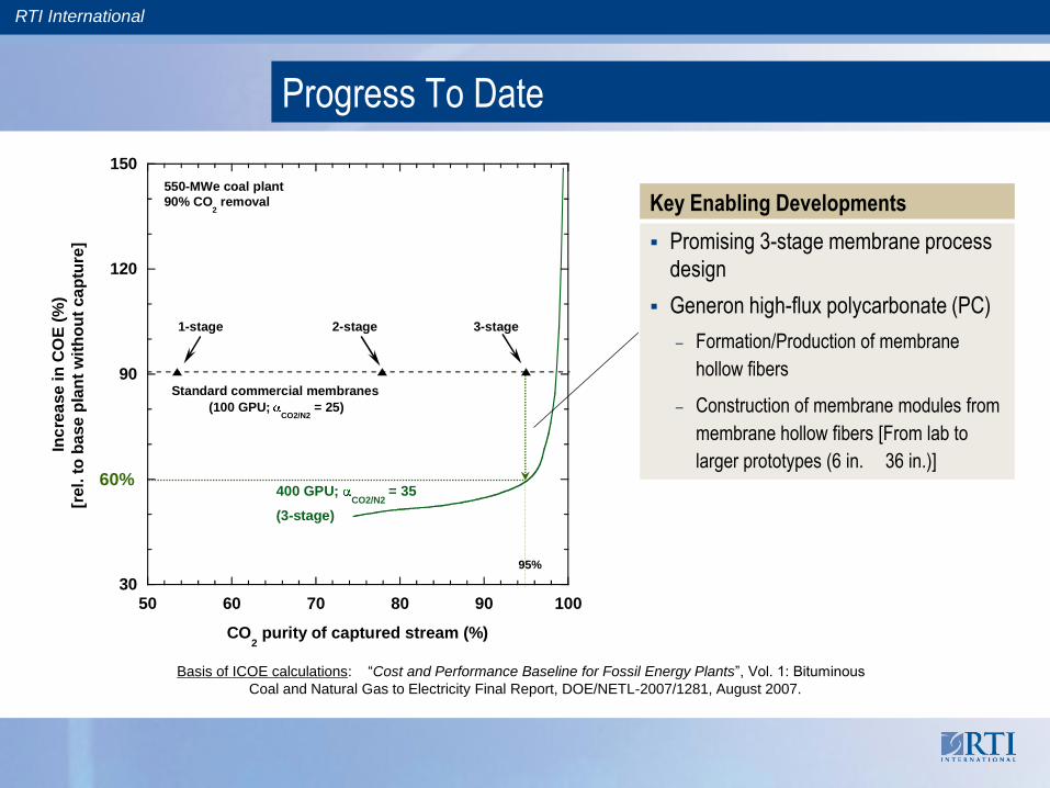
Standard commercial membranes
(100 GPU; CO2/N2
= 25)
550-MWe coal plant
90% CO2 removal
400 GPU; CO2/N2
= 35
(3-stage)
1-stage 2-stage 3-stage
Progress To Date
95%
60%
Key Enabling Developments
Promising 3-stage membrane process
design
Generon high-flux polycarbonate (PC)
– Formation/Production of membrane
hollow fibers
– Construction of membrane modules from
membrane hollow fibers [From lab to
larger prototypes (6 in. 36 in.)]
Basis of ICOE calculations: ―Cost and Performance Baseline for Fossil Energy Plants‖, Vol. 1: Bituminous
Coal and Natural Gas to Electricity Final Report, DOE/NETL-2007/1281, August 2007.

RTI International
Membrane hollow fibers from high-flux PC were successfully formed.
– Mechanically durable up to at least 10,000 pressure cycles at
135 psig minimum pressure
New high-flux PC fibers spun have
– CO2 permeance 4 times faster than that of standard PC fibers
– CO2/N2 selectivity similar to that of standard PC fibers
Generon Polycarbonate (PC) Membrane PlatformNext-Generation, High-Flux PC vs. Standard PC
Individual Generon
hollow membrane fibers
Generon lab-scale hollow-fiber
membrane modules
* Intrinsic CO2/N2 selectivity obtained on high-flux PC films was 35-37.
1 GPU = 1 × 10⁻⁶ cm3(STP)/(cm2·s·cmHg)
Fibers with 25% larger dimensions were also successfully spun as an
option for mitigation of pressure drops (50% lower).
Production of larger prototype modules (6 in. × 36 in.) with properties
similar to the smaller lab-scale modules was completed recently.
Hollow-fiber
module
Gas permeance (GPU) Gas selectivity
N2 O2 CO2 SO2 O2/N2 CO2/N2 SO2/N2
Standard PC 4.0 26 100 130 6.5 25 32
High-flux PC* 19 100 410 575 5.3 22 30

RTI International
Compression and dehydration
25% CO2
65 psia
65% CO2
70 psia
13% CO2
Combustionair sweep
Flue-gas
Coal
M1
M2
M3
Expander
Boiler
Compressor
6,855 lb/min
9.9% CO2
14.7 psia
CO2 capture stream
95% CO2
538 acfm2,215 psia
Compressor
1.7% CO2
6 × 10⁵ acfm14.7 psia
To stack
38% CO2
21% CO2
1.3 × 10⁶ acfm
14.7 psia
65% CO2
14.7 psia
RTI 3-Stage Membrane Process Design
550-MWe PC Plant with 90% CO2 Capture
Generon high-flux polycarbonate membrane
(400 GPU; CO2/N2 = 35)
Membrane area = 2.45 106 m2
ICOE = 59%
$30/ton CO2 captured
$42/ton CO2 avoided
Pipeline CO2 purity target
Minimum 95% CO2 used(Kinder Morgan CO2 Company, L.P.
specifications)
For very high CO2 purity (99.5%),
additional post-polishing step would
be needed for more cost-effective
removal of residual impurities
(N2, O2).
RTI International
30
60
90
120
150
70 80 90 100
Inc
rea
se
in
CO
E (
%)
[re
l. t
o b
as
e p
lan
t w
ith
ou
t c
ap
ture
]
CO2 purity of captured stream (%)
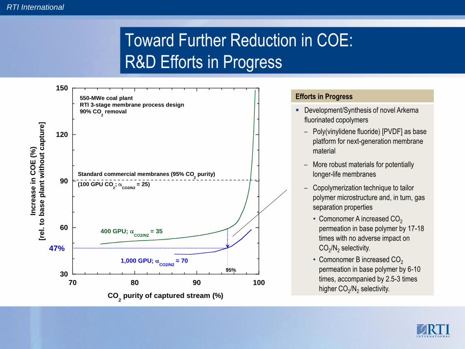
Standard commercial membranes (95% CO2 purity)
(100 GPU CO2;
CO2/N2 = 25)
550-MWe coal plant
RTI 3-stage membrane process design
90% CO2 removal
400 GPU; CO2/N2
= 35
1,000 GPU; CO2/N2
= 70
Toward Further Reduction in COE:
R&D Efforts in Progress
47%
95%
Efforts in Progress
Development/Synthesis of novel Arkema
fluorinated copolymers
– Poly(vinylidene fluoride) [PVDF] as base
platform for next-generation membrane
material
– More robust materials for potentially
longer-life membranes
– Copolymerization technique to tailor
polymer microstructure and, in turn, gas
separation properties
• Comonomer A increased CO2
permeation in base polymer by 17-18
times with no adverse impact on
CO2/N2 selectivity.
• Comonomer B increased CO2
permeation in base polymer by 6-10
times, accompanied by 2.5-3 times
higher CO2/N2 selectivity.

RTI International
— CF2 — CH2 —– +
μHigh dipole moment Highly polar
* From El-Hibri and Paul, J. Appl. Polym. Sci., Vol. 31, 2533 (1986).
1 GPU = 1 × 10⁻⁶ cm3(STP)/(cm2·s·cmHg)
PVDF-Based Membrane Material PlatformArkema
Polyvinylidene fluoride (PVDF)-based polymers
High oxidation resistance
– Used in O2/H2 fuel cell membrane compositions
High chemical resistance to acids
– Withstands nitric acid exposure with no dimensional
changes and weight loss
Ease of processing (solution or melt)
– Used for water purification as porous hollow fibers
Specific affinity for CO2
– High CO2 solubility due to high polar nature of
VDF repeat unit
PVDF homopolymer
Highly crystalline (up to 50-65%), reducing gas
transport
Low CO2 permeance ~ 5 GPU*(for 0.1-µm thickness)
Moderate CO2/N2 selectivity ~ 23*
PVDF repeat unit: –[CH2-CF2]n–
CC
H H
F F
CC
H H
F F
CC
H H
F F
CC
H H
F F
CC
H H
F F

RTI International
Copolymerization ApproachArkema
Copolymerize fluoro-comonomers with bulky pendant groups
into VDF backbone
– Bulky comonomer disrupts polymer-chain organization, reducing
crystallinity (down to <2%)
– Intrinsic gas permeability of PVDF increases
– Bulky perfluorinated Comonomer A successfully synthesized into
VDF backbone
Incorporate comonomers having greater dipole moments
– Enhances polymer affinity for CO2 to raise intrinsic CO2/N2
selectivity
– VDF copolymers with very polar, bulky Comonomer B successfully
made
• Dipole of Comonomer B >> Dipole of Comonomer A
PVDF backbone can be chemically modified.
– To increase permeability by lowering crystallinity
– To have higher CO2 selectivity by changing backbone
dipole moments

RTI International
VDF-Based Copolymers: CO2 Permeance
Improvement
Gas permeance
0
50
100
150
200
Gas p
erm
ean
ce (
GP
U)
Increasing Comonomer A content
CO2
O2
N2
VDF-co-A series
Gas/N2 selectivity
1
10
100
Gas s
ele
cti
vit
yIncreasing Comonomer A content
CO2/N
2
O2/N
2
VDF-co-A series
T = 35 °C; 1 GPU = 1 × 10⁻⁶ cm3(STP)/(cm2·s·cmHg)
Addition of bulky Comonomer A into the VDF backbone resulted in
18-fold increase in CO2 permeance
No adverse impact on CO2/N2 selectivity

RTI International
VDF-Based Copolymers: Effect of Temperature
and More Polar Bulky Comonomer
Substantial 10-fold increase in CO2
permeance (>450 GPU) over only a small 35 C temperature interval
VDF-based copolymer properties can be tuned/optimized through
process conditions (e.g., temperature) and proper comonomer
selection and addition into chain backbone.
Permeance vs. temperature More polar comonomer on selectivity
1 GPU = 1 × 10⁻⁶ cm3(STP)/(cm2·s·cmHg)
0
100
200
300
400
500
20 30 40 50 60 70
Gas p
erm
ean
ce (
GP
U)
Temperature (°C)
CO2
O2
N2
VDF-co-A copolymer
0
10
20
30
40
50
60
70
80
O2/N
2
CO2/N
2
Gas
se
lec
tivit
y
VDF-co-B series
Increasing Comonomer B content
Base B.2 B.3 B.1 B.4
2.5-3 times higher CO2/N2 selectivity (>70), accompanied by 6-fold increase in CO2
permeance

RTI International
Effect of NO and NO2 on CO2 PermeanceGeneron High-Flux PC vs. Arkema VDF-Based Copolymer
0.0
0.2
0.4
0.6
0.8
1.0
1.2
0 50 100 150 200
No
rmali
zed
mix
ed
-ga
s C
O2 p
erm
ean
ce
Time (h)
Generon high-flux
polycarbonate
Arkema VDF-A.2 copolymer
Feed: 255 ppm NO 15% CO2, Balance N
2
T = 23 °C
255 ppm NO in CO2/N2 feed
0.0
0.2
0.4
0.6
0.8
1.0
1.2
0 50 100 150 200
No
rmali
zed
mix
ed
-ga
s C
O2 p
erm
ean
ce
Time (h)
Generon high-flux
polycarbonate
Arkema VDF-A.2 copolymer
Feed: 31 ppm NO2, 15% CO
2, Balance N
2
T = 23 °C
31 ppm NO2 in CO2/N2 feed
VDF-based copolymers are less sensitive to NOx than high-flux PC.

RTI International
Effect of NO and NO2 on CO2/N2 SelectivityGeneron High-Flux PC
0
0.2
0.4
0.6
0.8
1
1.2
1.4
0 50 100 150 200
No
rmali
zed
mix
ed
-ga
s
CO
2/N
2 s
ele
cti
vit
y
Time (h)
255 ppm NO, 15% CO2, Bal. N
2
Generon high-flux polycarbonate
T = 23 °C
31 ppm NO2, 15% CO
2, Bal. N
2
No selectivity loss occurs in high-flux PC in presence of NOx.

RTI International
20
40
60
80
100
120
140
160
70 80 90 100
Inc
rea
se
in
CO
E (
%)
[re
l. t
o b
as
e p
lan
t w
ith
ou
t c
ap
ture
]
CO2 purity of captured stream (%)
Standard commercial membranes (95% CO2 purity)
(100 GPU CO2;
CO2/N2 = 25)
550-MWe coal plant
RTI 3-stage membrane process design
90% CO2 removal
400 GPU; CO2/N2
= 35
1,000 GPU; CO2/N2
= 70
35% ICOE target
Path Forward To DOE Target for ICOE
95%
Future R&D Directions
Membrane materials development
Continued focus on improved chemical durability
Optimization of hollow-fiber membrane module engineering design
Alternative ways to create transmembrane driving force for separation

RTI International
Summary
Development and synthesis of Arkema VDF-based copolymers with
improved CO2 permeance and improved CO2/N2 selectivity
– 17-18 times higher CO2 and permeability than base polymer; No adverse
impact on base CO2/N2 selectivity (VDF-co-A)
– 2.5-3 times higher CO2/N2 selectivity and 6 times higher CO2 permeability
than base polymer (VDF-co-B)
– No detrimental interaction effect of SO2 and NOx on Arkema copolymers
Development and scale-up of Generon high-flux polycarbonate (PC)
membrane fibers with up to 4 times higher CO2 flux than that of
Generon standard PC fiber
Successful formation of high-flux PC fibers into good lab-scale
modules and larger prototype field modules
Identification of promising 3-stage CO2 capture membrane process
design to achieve 90% CO2 capture and 95% CO2 purity

RTI International
Next Steps
Generon® module sizes
(100-10,000 ft2 or 10-1,000 m2)
Focus on increasing CO2 permeance and selectivity of Arkema novel copolymers
– Blend of VDF-co-B w/ PVDF as minor phase
– Terpolymer of VDF-co-A-co-B synthesized with high concentrations of these comonomers
Downselect promising Arkema copolymer candidates to evaluate for hollow-fiber fabrication
Design and construction of field-test membrane skid
Field test (1,000 h cumulative) of prototype high-flux PC membrane modules with real coal flue gas (robustness; performance stability; process design validation; etc.)
Techno-economic analysis of ―best‖ integrated/retrofitted CO2 capture membrane process package in pulverized coal plant
RTI syngas membrane test skid

RTI International
Field Test of Capture Membrane Process:
Site and Plans In Progress
a UNC-CH = The University of North Carolina at Chapel Hill; b Membrane module
area ~ 2,200 ft2 (Type 6150); 1,100 ft2 (Type 4150); 100 ft2 (Type 210)
Stack
Baghouse
Coal Bunker
Limestone
Admin Building
Enclosed CFBs
Stack
Baghouse
Coal Bunker
Limestone
Admin Building
Enclosed CFBs
UNC-Chapel Hill
Coal-Fired Power Plant (32 MWe) UNC-CHa Cogeneration Power Plant (Chapel Hill, NC)
Combustor
operation
~32-MWe;1,000 tpd CO2 produced;
Continuous 24/7 operation
Test duration 1,000 h
Skid design3-stage membrane process; (M1, M2, and M3
stages); Target of 1-tpd CO2 captured
Membrane
modules
1 Type 6150b module for M1
+ 1 Type 4150b module for M3
+ 2 Type 210b modules for M2
Field-test
objectives
(i) Demonstrate field performance of RTI’s 3-stage membrane process design for 90% CO2 removal.
(ii) Investigate membrane module stability (structural and performance) to real coal flue-gas.
(iii) Study membrane durability/stability to real flue gas in extended field testing.
RTI International
Acknowledgements
U.S. DOE/NETL
José Figueroa
Lynn Brickett
Jared Ciferno