Embed Size (px)
Citation preview
CNOC: High-‐Radix Clos Network-‐on-‐Chip
Yu-‐Hsiang Kao Advisor – H. Jonathan Chao
Outline • IntroducCon
– Chip MulCprocessors (CMP) – Previous Network-‐on-‐Chip (NoC) Topologies and their respecCve
problems – Clos Network-‐on-‐Chip (CNOC)
• Research Issues • Proposed soluCons
– The scheduling algorithm of CNOC – The design of the Hierarchical Round-‐Robin Arbiter (HRRA) – The floorplanning methodology of CNOC
• Experimental results • Conclusion
2
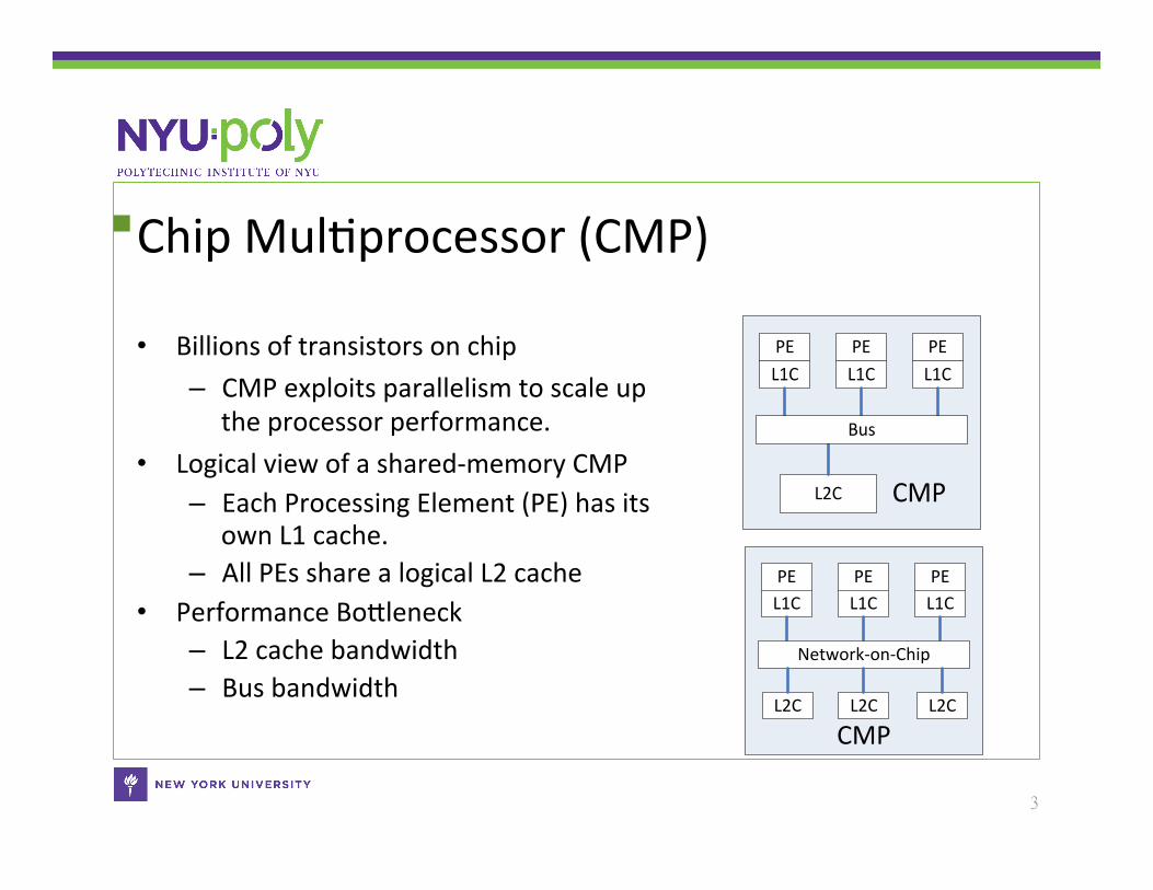
Chip MulCprocessor (CMP)
• Billions of transistors on chip – CMP exploits parallelism to scale up
the processor performance. • Logical view of a shared-‐memory CMP
– Each Processing Element (PE) has its own L1 cache.
– All PEs share a logical L2 cache • Performance BoSleneck
– L2 cache bandwidth – Bus bandwidth
3
CMPL2C
PEL1C
PEL1C
PEL1C
Bus
CMP
PEL1C
PEL1C
PEL1C
Network-‐on-‐Chip
L2C L2C L2C
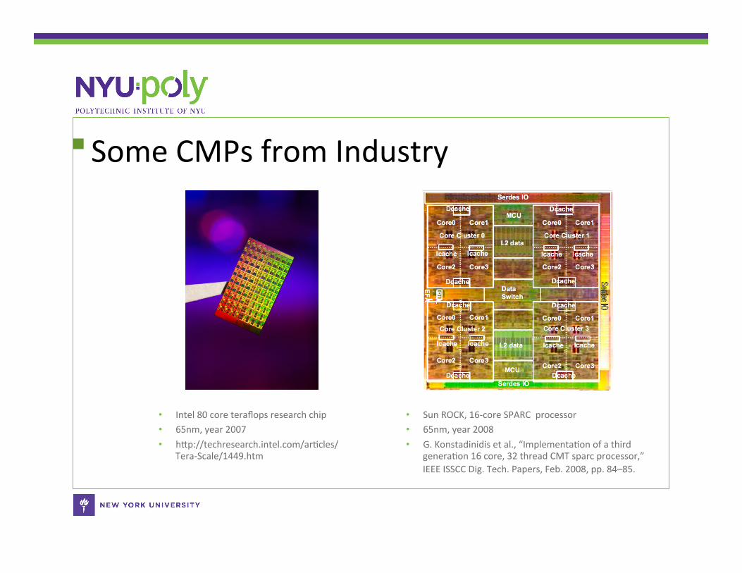
Some CMPs from Industry
• Intel 80 core teraflops research chip • 65nm, year 2007 • hSp://techresearch.intel.com/arCcles/
Tera-‐Scale/1449.htm
• Sun ROCK, 16-‐core SPARC processor • 65nm, year 2008 • G. Konstadinidis et al., “ImplementaCon of a third
generaCon 16 core, 32 thread CMT sparc processor,” IEEE ISSCC Dig. Tech. Papers, Feb. 2008, pp. 84–85.
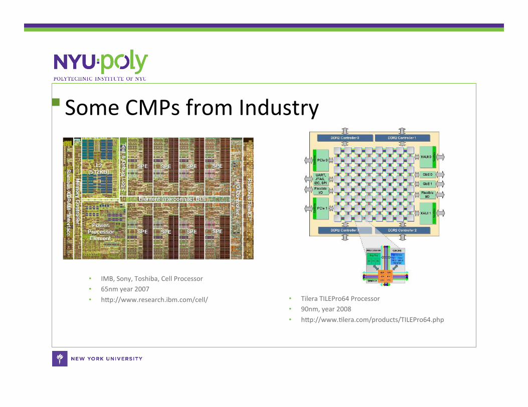
Some CMPs from Industry
• IMB, Sony, Toshiba, Cell Processor • 65nm year 2007 • hSp://www.research.ibm.com/cell/ • Tilera TILEPro64 Processor
• 90nm, year 2008 • hSp://www.Clera.com/products/TILEPro64.php
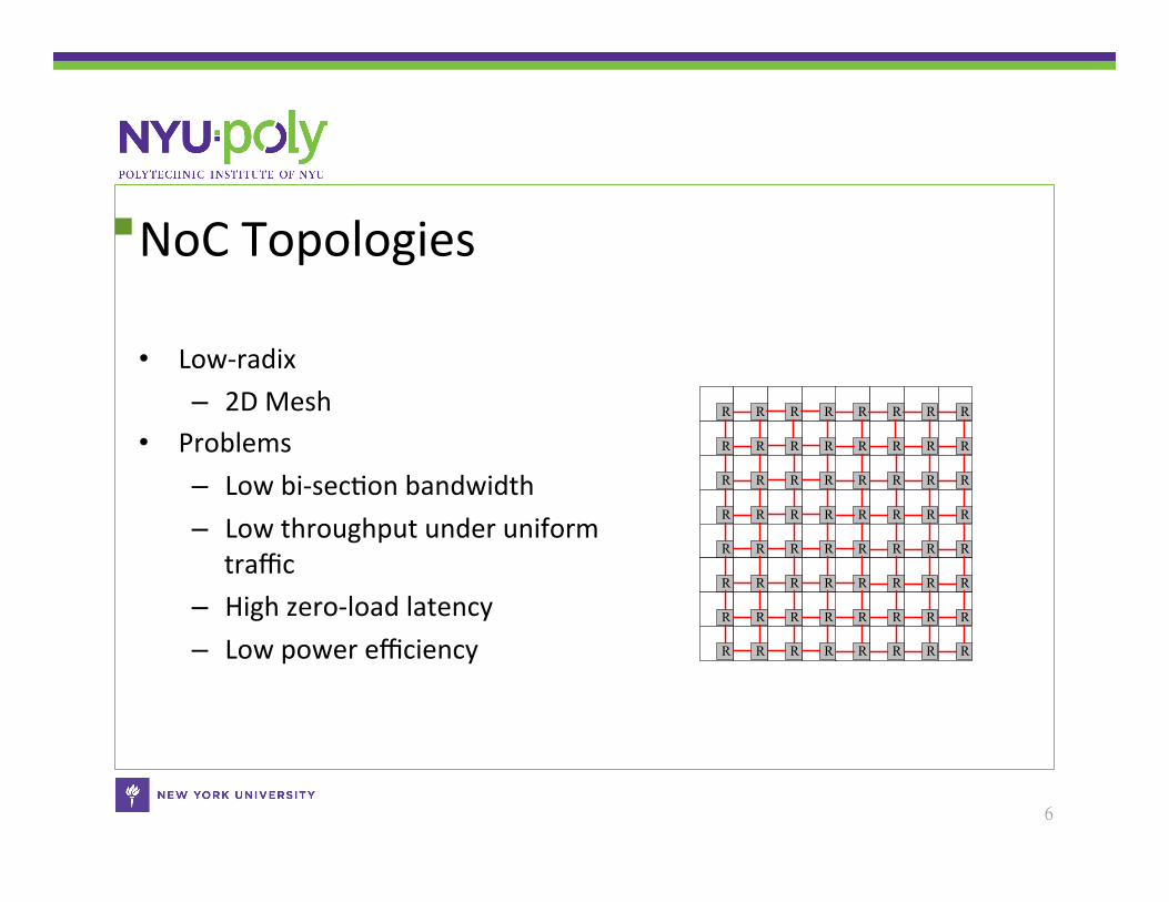
NoC Topologies
• Low-‐radix – 2D Mesh
• Problems – Low bi-‐secCon bandwidth – Low throughput under uniform
traffic – High zero-‐load latency – Low power efficiency
6
R R R R RR RR
R R R R RR RR
R R R R RR RR
R R R R RR RR
R R R R RR RR
R R R R RR RR
R R R R RR RR
R R R R RR RR
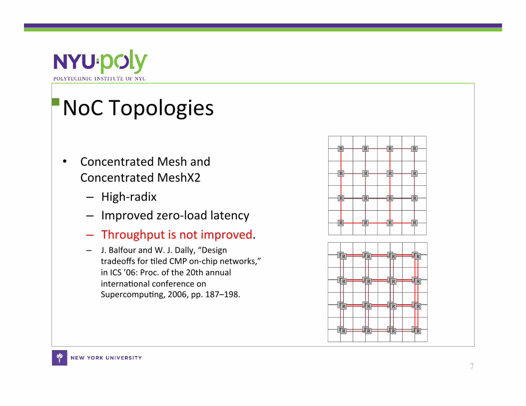
NoC Topologies
• Concentrated Mesh and Concentrated MeshX2 – High-‐radix – Improved zero-‐load latency – Throughput is not improved. – J. Balfour and W. J. Dally, “Design
tradeoffs for Cled CMP on-‐chip networks,” in ICS ’06: Proc. of the 20th annual internaConal conference on SupercompuCng, 2006, pp. 187–198.
7
R R R R
R R R R
R R R R
R R R R
R R R R
R R R R
R R R R
R R R R
R R R R
R R R R
R R R R
R R R R
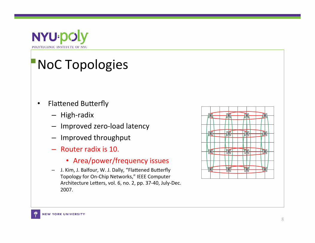
NoC Topologies
• FlaSened BuSerfly – High-‐radix – Improved zero-‐load latency – Improved throughput – Router radix is 10.
• Area/power/frequency issues – J. Kim, J. Balfour, W. J. Dally, “FlaSened BuSerfly
Topology for On-‐Chip Networks,” IEEE Computer Architecture LeSers, vol. 6, no. 2, pp. 37-‐40, July-‐Dec. 2007.
8
R R R R
R R R R
R R R R
R R R R
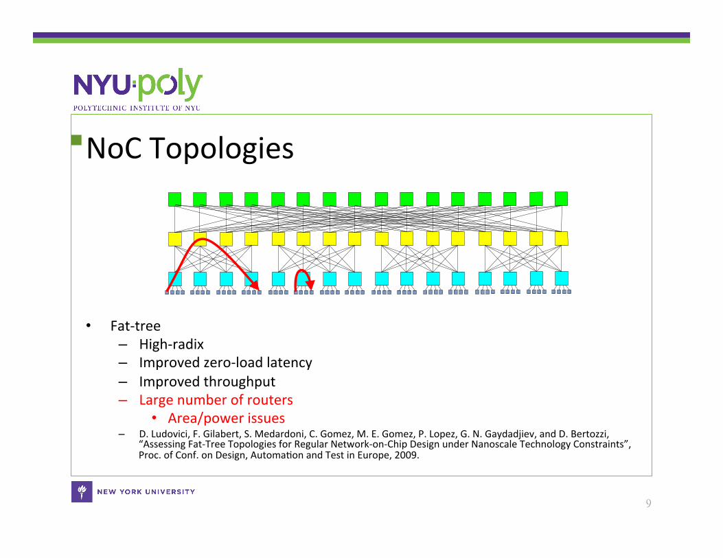
NoC Topologies
• Fat-‐tree – High-‐radix – Improved zero-‐load latency – Improved throughput – Large number of routers
• Area/power issues – D. Ludovici, F. Gilabert, S. Medardoni, C. Gomez, M. E. Gomez, P. Lopez, G. N. Gaydadjiev, and D. Bertozzi,
“Assessing Fat-‐Tree Topologies for Regular Network-‐on-‐Chip Design under Nanoscale Technology Constraints”, Proc. of Conf. on Design, AutomaCon and Test in Europe, 2009.
9
NoC Topologies
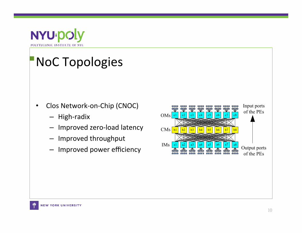
• Clos Network-‐on-‐Chip (CNOC) – High-‐radix – Improved zero-‐load latency – Improved throughput – Improved power efficiency
10
OMs
CMs
IMs
c1 c2 c3 c4 c5 c6 c7 c8
b1 b2 b3 b4 b5 b6 b7 b8
a1 a2 a3 a4 a5 a6 a7 a8Output ports of the PEs
Input ports of the PEs
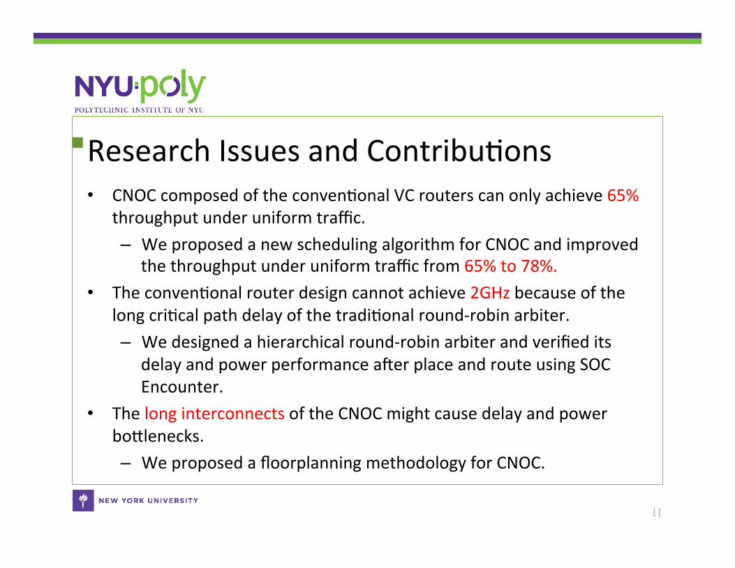
Research Issues and ContribuCons • CNOC composed of the convenConal VC routers can only achieve 65%
throughput under uniform traffic. – We proposed a new scheduling algorithm for CNOC and improved
the throughput under uniform traffic from 65% to 78%. • The convenConal router design cannot achieve 2GHz because of the
long criCcal path delay of the tradiConal round-‐robin arbiter. – We designed a hierarchical round-‐robin arbiter and verified its
delay and power performance aoer place and route using SOC Encounter.
• The long interconnects of the CNOC might cause delay and power boSlenecks. – We proposed a floorplanning methodology for CNOC.
11
Outline • IntroducCon
– Chip MulCprocessors (CMP) – Previous Network-‐on-‐Chip (NoC) Topologies and their respecCve
problems – Clos Network-‐on-‐Chip (CNOC)
• Research Issues • Proposed soluCons
– The scheduling algorithm of CNOC – The design of the Hierarchical Round-‐Robin Arbiter (HRRA) – The floorplanning methodology of CNOC
• Experimental results • Conclusion
12
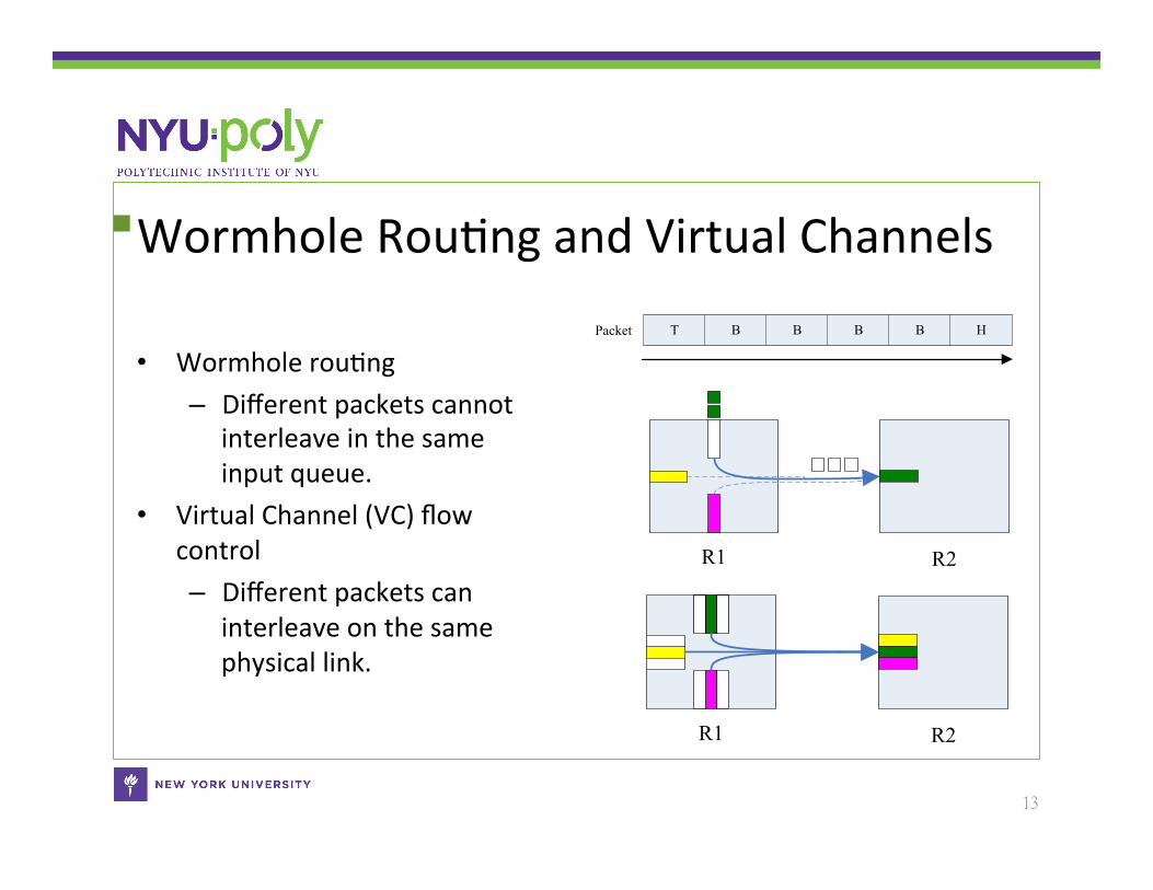
Wormhole RouCng and Virtual Channels
• Wormhole rouCng – Different packets cannot
interleave in the same input queue.
• Virtual Channel (VC) flow control – Different packets can
interleave on the same physical link.
13
TPacket B B B B H
R2R1
R2R1
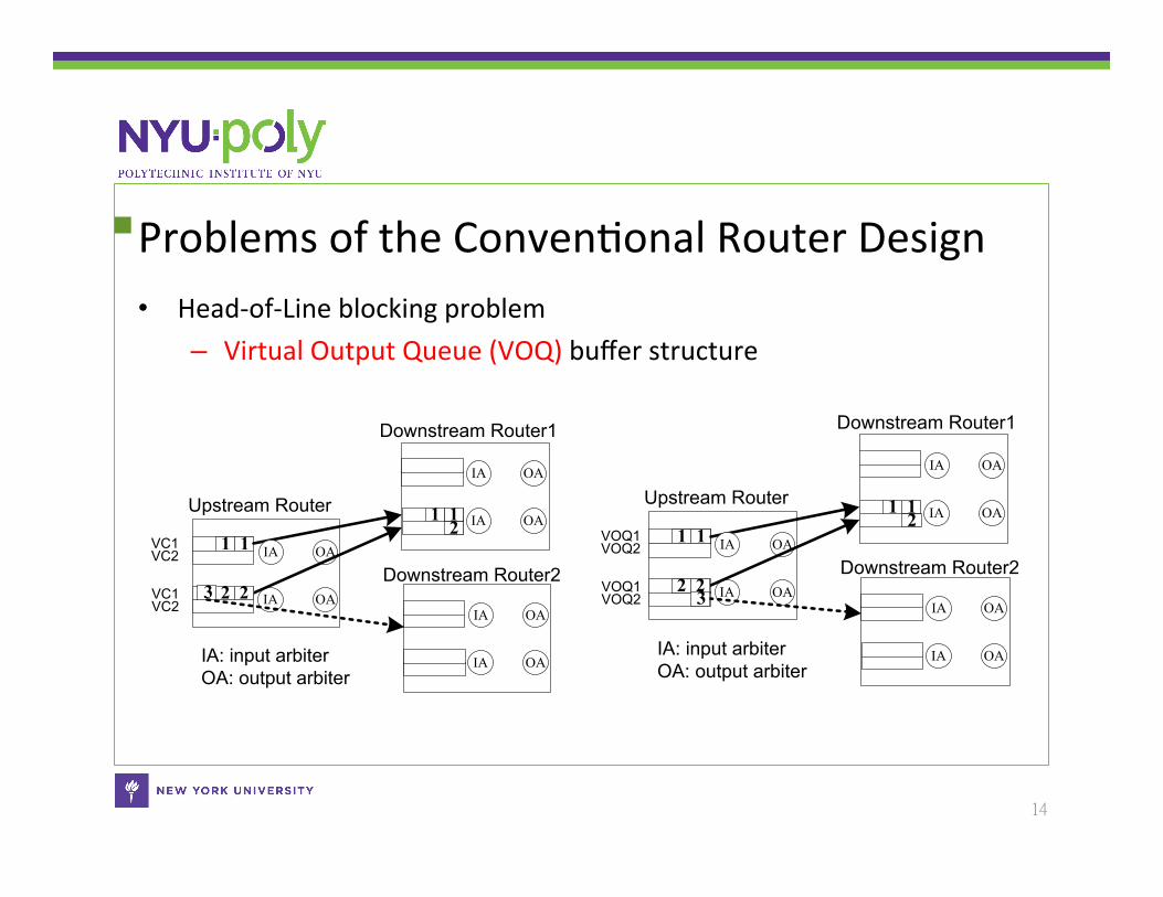
Problems of the ConvenConal Router Design • Head-‐of-‐Line blocking problem
– Virtual Output Queue (VOQ) buffer structure
14
Upstream Router
VC2VC1
VC2VC1
11 IA
IA
OA
OAIA
IA
OA
OA
Downstream Router1
IA
IA
OA
OA11
Downstream Router2
IA: input arbiterOA: output arbiter
2
223
Upstream Router
VOQ2VOQ1
VOQ2VOQ1
11 IA
IA
OA
OAIA
IA
OA
OA
Downstream Router1
IA
IA
OA
OA11
Downstream Router2
IA: input arbiterOA: output arbiter
2
223
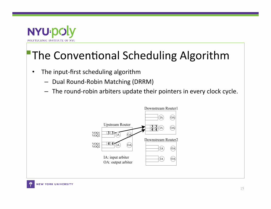
The ConvenConal Scheduling Algorithm • The input-‐first scheduling algorithm
– Dual Round-‐Robin Matching (DRRM) – The round-‐robin arbiters update their pointers in every clock cycle.
15
Upstream Router
VOQ2VOQ1
VOQ2VOQ1
33 IA
IA
OA
OAIA
IA
OA
OA
Downstream Router1
IA
IA
OA
OA33
Downstream Router2
IA: input arbiterOA: output arbiter
44
44
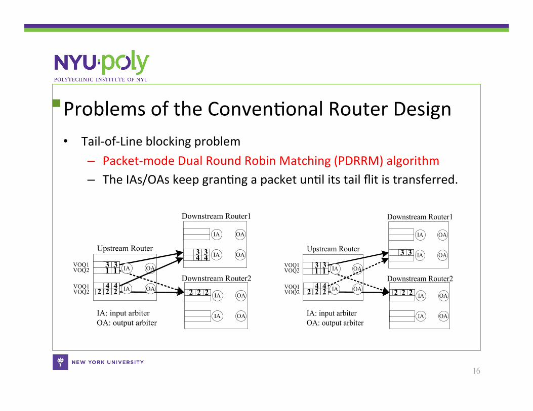
Problems of the ConvenConal Router Design • Tail-‐of-‐Line blocking problem
– Packet-‐mode Dual Round Robin Matching (PDRRM) algorithm – The IAs/OAs keep granCng a packet unCl its tail flit is transferred.
16
Upstream Router
VOQ2VOQ1
VOQ2VOQ1
1
2 2 2
1
222
33 IA
IA
OA
OAIA
IA
OA
OA
Downstream Router1
IA
IA
OA
OA33
Downstream Router2
IA: input arbiterOA: output arbiter
44
44Upstream Router
VOQ2VOQ1
VOQ2VOQ1
1
2 2 2
1
222
33 IA
IA
OA
OAIA
IA
OA
OA
Downstream Router1
IA
IA
OA
OA33
Downstream Router2
IA: input arbiterOA: output arbiter
44
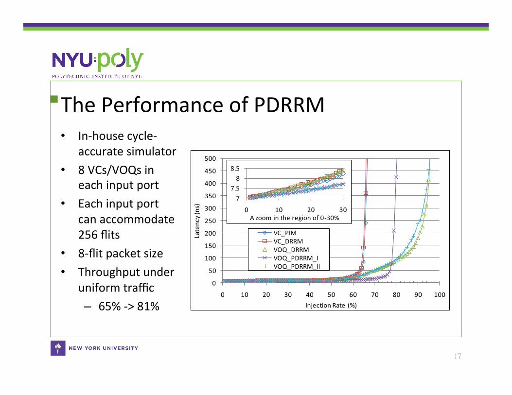
The Performance of PDRRM • In-‐house cycle-‐
accurate simulator • 8 VCs/VOQs in
each input port • Each input port
can accommodate 256 flits
• 8-‐flit packet size • Throughput under
uniform traffic – 65% -‐> 81%
17
0
50
100
150
200
250
300
350
400
450
500
0 10 20 30 40 50 60 70 80 90 100
Latency (ns)
Injection Rate (%)
VC_PIMVC_DRRMVOQ_DRRMVOQ_PDRRM_IVOQ_PDRRM_II
77.58
8.5
0 10 20 30A zoom in the region of 0-‐30%
Outline • IntroducCon
– Chip MulCprocessors (CMP) – Previous Network-‐on-‐Chip (NoC) Topologies and their respecCve
problems – Clos Network-‐on-‐Chip (CNOC)
• Research Issues • Proposed soluCons
– The scheduling algorithm of CNOC – The design of the Hierarchical Round-‐Robin Arbiter (HRRA) – The floorplanning methodology of CNOC
• Experimental results • Conclusion
18
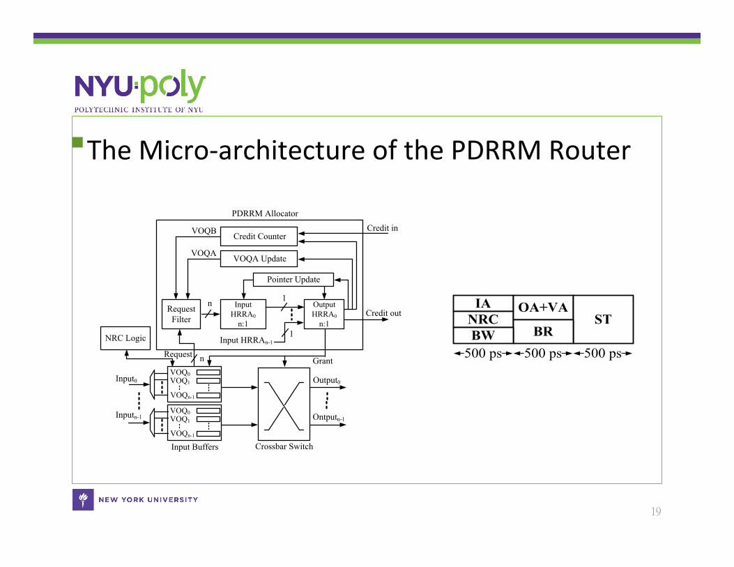
The Micro-‐architecture of the PDRRM Router
19
Request
VOQB
Grantn
n
VOQA
Credit in
1
Pointer Update
RequestFilter
InputHRRA0
n:1
VOQA Update
OutputHRRA0
n:1
Input HRRAn-1
Credit Counter
Credit out
1
VOQ0VOQ1
VOQn-1
Crossbar SwitchInput Buffers
VOQ0VOQ1
VOQn-1
Input0
Inputn-1
Output0
Ontputn-1
PDRRM Allocator
NRC Logic
IANRC
OA+VAST
500 ps 500 ps 500 psBRBW
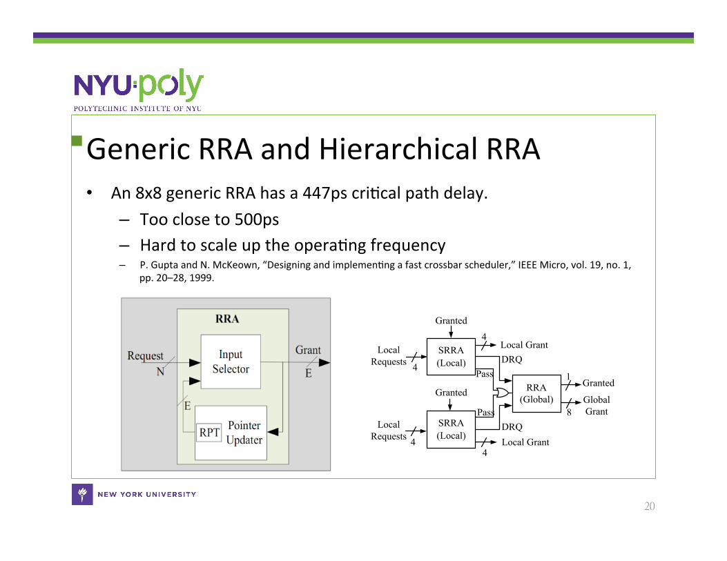
Generic RRA and Hierarchical RRA • An 8x8 generic RRA has a 447ps criCcal path delay.
– Too close to 500ps – Hard to scale up the operaCng frequency – P. Gupta and N. McKeown, “Designing and implemenCng a fast crossbar scheduler,” IEEE Micro, vol. 19, no. 1,
pp. 20–28, 1999.
20
LocalRequests
Local Grant
4
4
1 Granted
8Global Grant
SRRA(Local)
SRRA(Local)
4
RRA(Global)
Granted
Local Grant
LocalRequests
Granted
4
DRQ
DRQPass
Pass
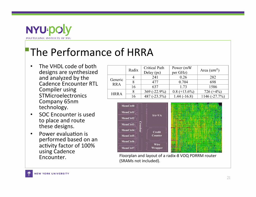
The Performance of HRRA • The VHDL code of both
designs are synthesized and analyzed by the Cadence Encounter RTL Compiler using STMicroelectronics Company 65nm technology.
• SOC Encounter is used to place and route these designs.
• Power evaluaCon is performed based on an acCvity factor of 100% using Cadence Encounter.
21
SA+VA
CreditCounter
WireWrapper
Crossbar
MemCtrl0
MemCtrl1
MemCtrl2
MemCtrl3
MemCtrl4
MemCtrl5
MemCtrl6
MemCtrl7
Floorplan and layout of a radix-‐8 VOQ PDRRM router (SRAMs not included).
Outline • IntroducCon
– Chip MulCprocessors (CMP) – Previous Network-‐on-‐Chip (NoC) Topologies and their respecCve
problems – Clos Network-‐on-‐Chip (CNOC)
• Research Issues • Proposed soluCons
– The scheduling algorithm of CNOC – The design of the Hierarchical Round-‐Robin Arbiter (HRRA) – The floorplanning methodology of CNOC
• Experimental results • Conclusion
22
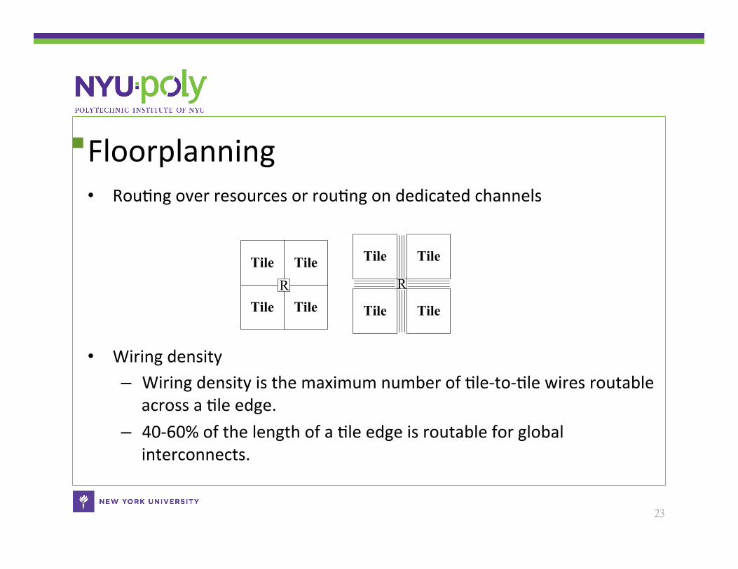
Floorplanning • RouCng over resources or rouCng on dedicated channels
• Wiring density – Wiring density is the maximum number of Cle-‐to-‐Cle wires routable
across a Cle edge. – 40-‐60% of the length of a Cle edge is routable for global
interconnects.
Tile Tile
Tile TileR
Tile Tile
Tile Tile
R
23
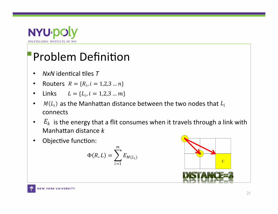
Problem DefiniCon • NxN idenCcal Cles T • Routers • Links • as the ManhaSan distance between the two nodes that
connects • is the energy that a flit consumes when it travels through a link with
ManhaSan distance k • ObjecCve funcCon:
𝑅 = {𝑅𝑖, 𝑖 = 1,2,3…𝑛}
𝐿 = {𝐿𝑖 , 𝑖 = 1,2,3…𝑚} 𝑀(𝐿𝑖) 𝐿𝑖
𝐸𝑘
C
A
BΦ(𝑅, 𝐿) =(𝐸𝑀(𝐿𝑖)
𝑚
𝑖=1
24
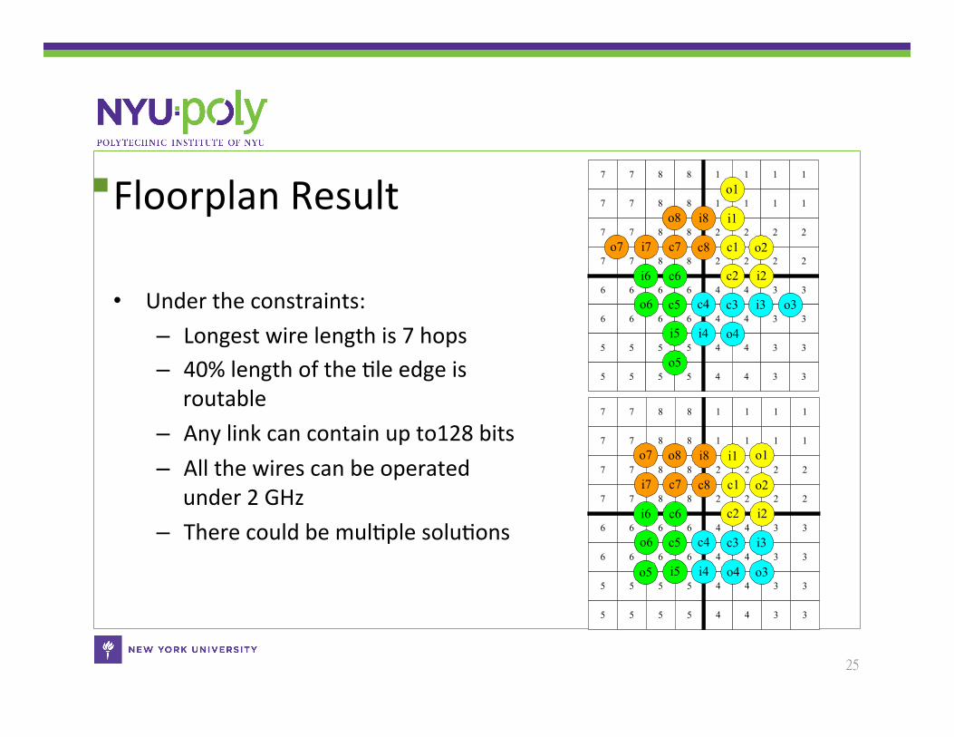
Floorplan Result
• Under the constraints: – Longest wire length is 7 hops – 40% length of the Cle edge is
routable – Any link can contain up to128 bits – All the wires can be operated
under 2 GHz – There could be mulCple soluCons
1
1
1
1
1
1
1
1
2
2
2
2
2
2
2
2
7
7
7
7
8
8
8
8
7
7
7
7
8
8
8
8
4
4
4
4
3
3
3
3
4
4
4
4
3
3
3
3
6
6
6
6
6
6
6
6
5
5
5
5
5
5
5
5
i6
o6
c6
c5
i5
o5
i4 o4
c4 c3 i3 o3
i2
o2
c2
c1
i1
o1
i8o8
c8c7i7o7
1
1
1
1
1
1
1
1
2
2
2
2
2
2
2
2
7
7
7
7
8
8
8
8
7
7
7
7
8
8
8
8
4
4
4
4
3
3
3
3
4
4
4
4
3
3
3
3
6
6
6
6
6
6
6
6
5
5
5
5
5
5
5
5
i6
o6
c6
c5
i5o5 i4 o4
c4 c3 i3
o3
i2
o2
c2
c1
i1 o1i8o8
c8c7i7
o7
25
Outline • IntroducCon
– Chip MulCprocessors (CMP) – Previous Network-‐on-‐Chip (NoC) Topologies and their respecCve
problems – Clos Network-‐on-‐Chip (CNOC)
• Research Issues • Proposed soluCons
– The scheduling algorithm of CNOC – The design of the Hierarchical Round-‐Robin Arbiter (HRRA) – The floorplanning methodology of CNOC
• Experimental results • Conclusion
26
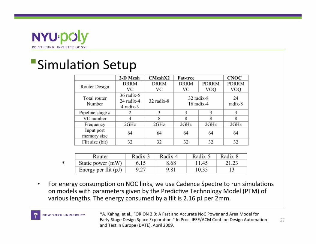
SimulaCon Setup
• For energy consumpCon on NOC links, we use Cadence Spectre to run simulaCons on models with parameters given by the PredicCve Technology Model (PTM) of various lengths. The energy consumed by a flit is 2.16 pJ per 2mm.
27 *A. Kahng, et al., “ORION 2.0: A Fast and Accurate NoC Power and Area Model for Early-‐Stage Design Space ExploraCon.” In Proc. IEEE/ACM Conf. on Design AutomaCon and Test in Europe (DATE), April 2009.
*
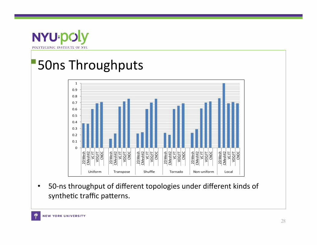
50ns Throughputs
• 50-‐ns throughput of different topologies under different kinds of syntheCc traffic paSerns.
28
0
0.1
0.2
0.3
0.4
0.5
0.6
0.7
0.8
0.9
12D
Mesh
CMeshX
2VC
FTVO
Q FT
CNOC
2D Mesh
CMeshX
2VC
FTVO
Q FT
CNOC
2D Mesh
CMeshX
2VC
FTVO
Q FT
CNOC
2D Mesh
CMeshX
2VC
FTVO
Q FT
CNOC
2D Mesh
CMeshX
2VC
FTVO
Q FT
CNOC
2D Mesh
CMeshX
2VC
FTVO
Q FT
CNOC
Uniform Transpose Shuffle Tornado Non-‐uniform Local
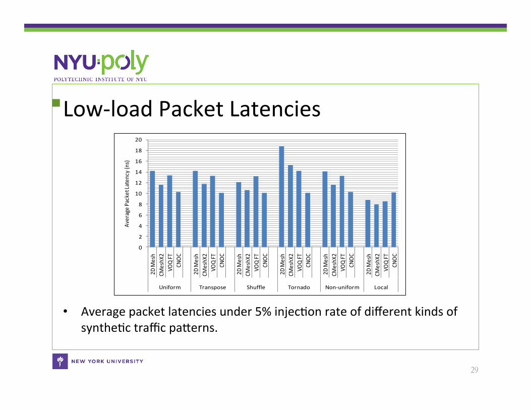
Low-‐load Packet Latencies
• Average packet latencies under 5% injecCon rate of different kinds of syntheCc traffic paSerns.
29
0
2
4
6
8
10
12
14
16
18
20
2D Mesh
CMeshX
2VO
Q FT
CNOC
2D Mesh
CMeshX
2VO
Q FT
CNOC
2D Mesh
CMeshX
2VO
Q FT
CNOC
2D Mesh
CMeshX
2VO
Q FT
CNOC
2D Mesh
CMeshX
2VO
Q FT
CNOC
2D Mesh
CMeshX
2VO
Q FT
CNOC
Uniform Transpose Shuffle Tornado Non-‐uniform Local
Average P
acket Laten
cy (n
s)
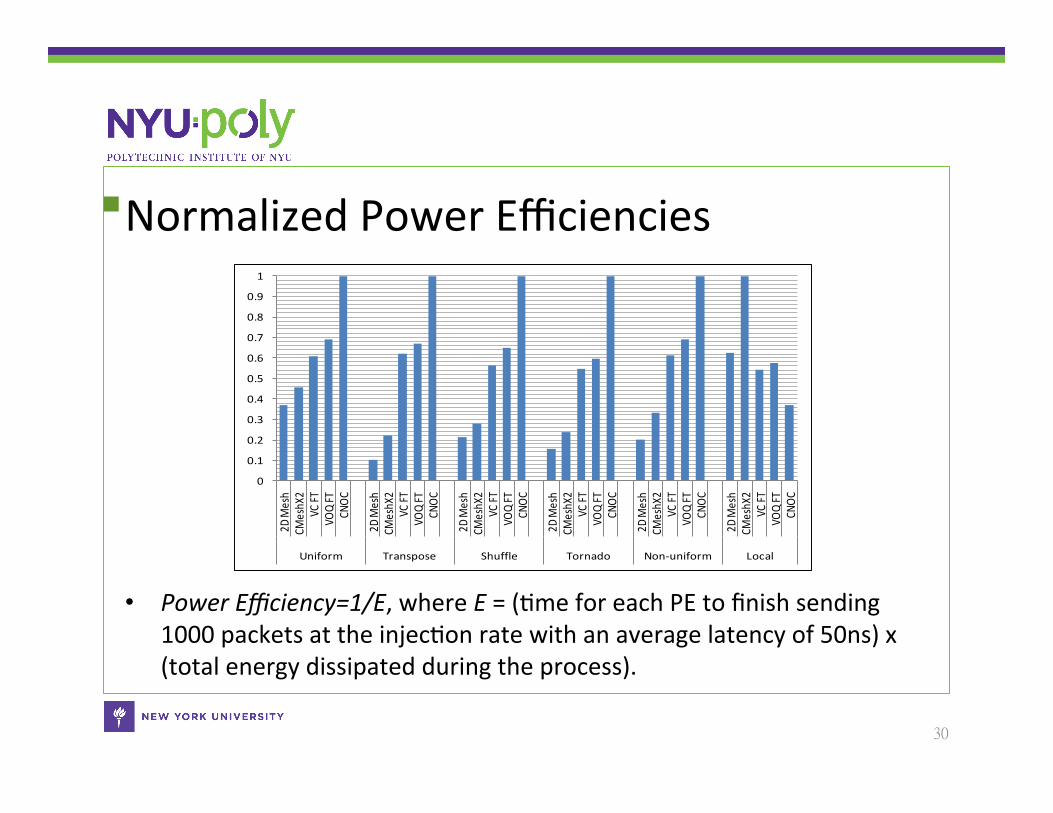
Normalized Power Efficiencies
• Power Efficiency=1/E, where E = (Cme for each PE to finish sending 1000 packets at the injecCon rate with an average latency of 50ns) x (total energy dissipated during the process).
30
0
0.1
0.2
0.3
0.4
0.5
0.6
0.7
0.8
0.9
12D
Mesh
CMeshX
2VC
FTVO
Q FT
CNOC
2D Mesh
CMeshX
2VC
FTVO
Q FT
CNOC
2D Mesh
CMeshX
2VC
FTVO
Q FT
CNOC
2D Mesh
CMeshX
2VC
FTVO
Q FT
CNOC
2D Mesh
CMeshX
2VC
FTVO
Q FT
CNOC
2D Mesh
CMeshX
2VC
FTVO
Q FT
CNOC
Uniform Transpose Shuffle Tornado Non-‐uniform Local
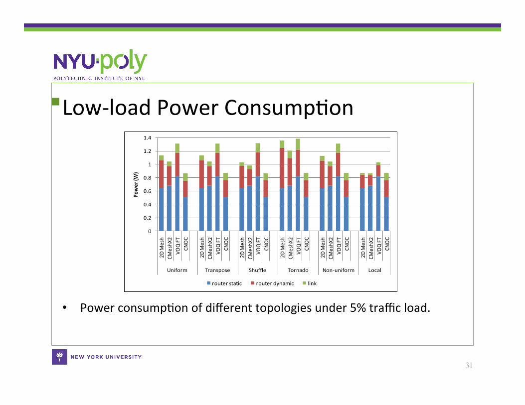
Low-‐load Power ConsumpCon
• Power consumpCon of different topologies under 5% traffic load.
31
0
0.2
0.4
0.6
0.8
1
1.2
1.4
2D Mesh
CMeshX
2VO
Q FT
CNOC
2D Mesh
CMeshX
2VO
Q FT
CNOC
2D Mesh
CMeshX
2VO
Q FT
CNOC
2D Mesh
CMeshX
2VO
Q FT
CNOC
2D Mesh
CMeshX
2VO
Q FT
CNOC
2D Mesh
CMeshX
2VO
Q FT
CNOC
Uniform Transpose Shuffle Tornado Non-‐uniform Local
Power (W
)
router static router dynamic link
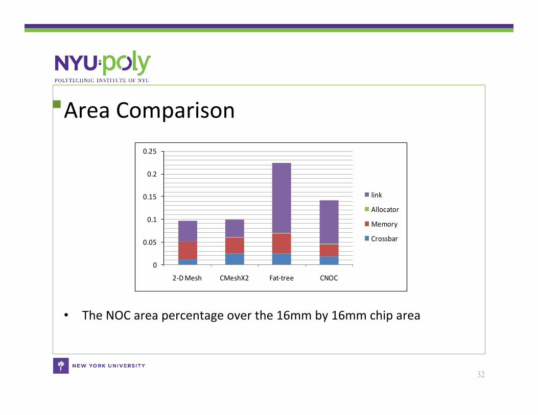
Area Comparison
• The NOC area percentage over the 16mm by 16mm chip area
32
0
0.05
0.1
0.15
0.2
0.25
2-‐D Mesh CMeshX2 Fat-‐tree CNOC
link
Allocator
Memory
Crossbar
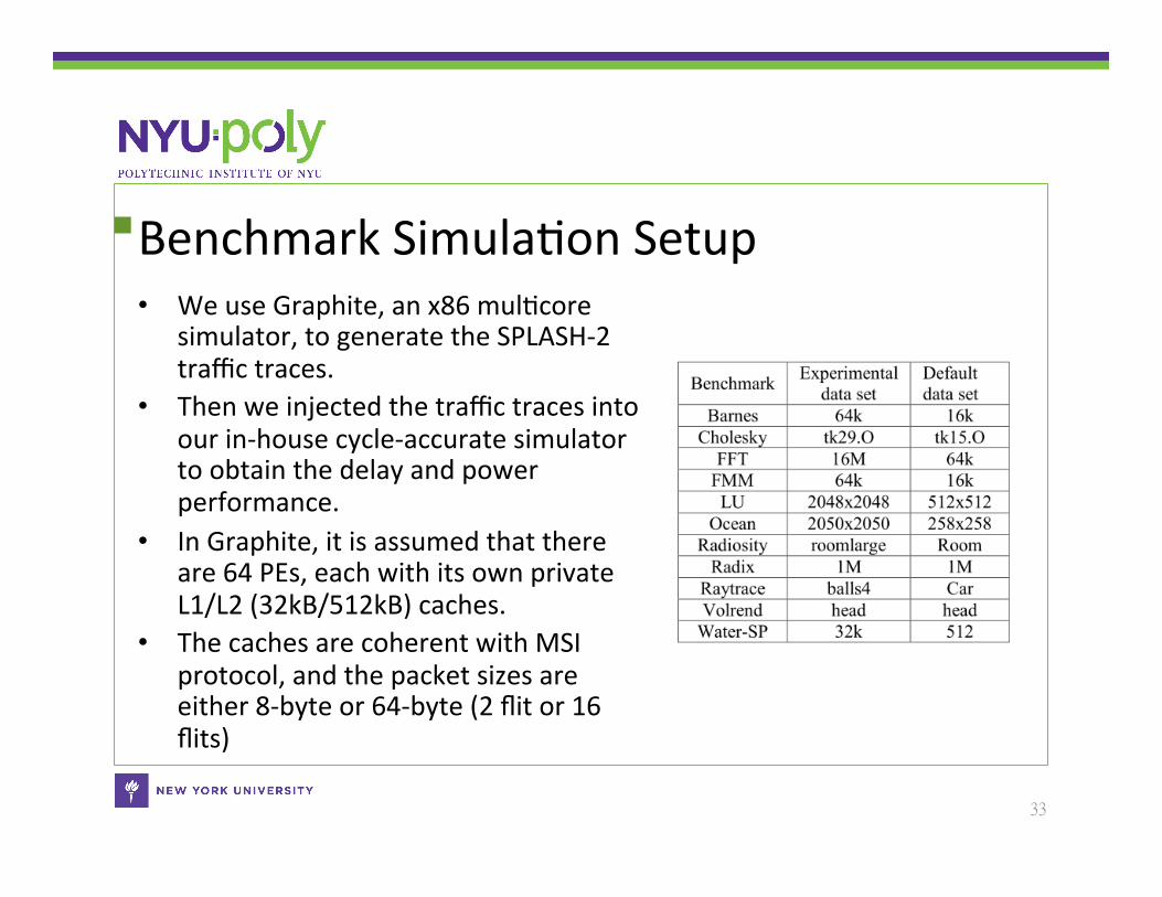
Benchmark SimulaCon Setup • We use Graphite, an x86 mulCcore
simulator, to generate the SPLASH-‐2 traffic traces.
• Then we injected the traffic traces into our in-‐house cycle-‐accurate simulator to obtain the delay and power performance.
• In Graphite, it is assumed that there are 64 PEs, each with its own private L1/L2 (32kB/512kB) caches.
• The caches are coherent with MSI protocol, and the packet sizes are either 8-‐byte or 64-‐byte (2 flit or 16 flits)
33
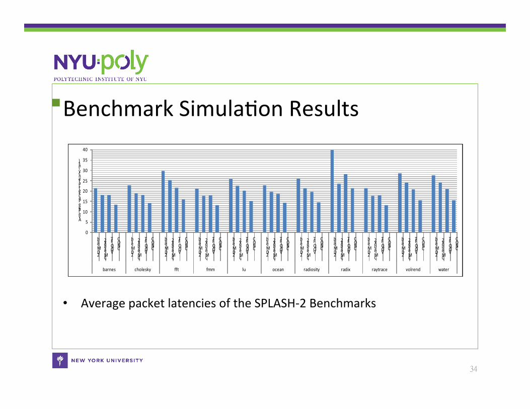
Benchmark SimulaCon Results
• Average packet latencies of the SPLASH-‐2 Benchmarks
34
0
5
10
15
20
25
30
35
40
2D Mesh
CMeshX2
VOQ FT
CNOC
2D Mesh
CMeshX2
VOQ FT
CNOC
2D Mesh
CMeshX2
VOQ FT
CNOC
2D Mesh
CMeshX2
VOQ FT
CNOC
2D Mesh
CMeshX2
VOQ FT
CNOC
2D Mesh
CMeshX2
VOQ FT
CNOC
2D Mesh
CMeshX2
VOQ FT
CNOC
2D Mesh
CMeshX2
VOQ FT
CNOC
2D Mesh
CMeshX2
VOQ FT
CNOC
2D Mesh
CMeshX2
VOQ FT
CNOC
2D Mesh
CMeshX2
VOQ FT
CNOC
barnes cholesky fft fmm lu ocean radiosity radix raytrace volrend water
Average Packet Latency (ns)
Conclusion • We proposed a new scheduling algorithm for CNOC and improved the
throughput with the convenConal scheduling algorithm under uniform traffic from 65% to 78%.
• We designed a hierarchical round-‐robin arbiter and verified its delay and power performance aoer place and route using SOC Encounter.
• We proposed a floorplanning methodology for CNOC. • We compared CNOC with 2D Mesh, CMeshX2, and Fat-‐tree in terms of
50-‐ns throughput, low-‐load latency, power efficiency, low-‐load power consumpCon, and average packet latencies under SPLASH-‐2 benchmarks.
• The works have been published in – IEEE/ACM NOCS 2010 – IEEE TCAD, issue of Dec. 2011
35

Thank You!
36