Embed Size (px)
Citation preview
www.ezcam.com
EZ-EDM Tutorials
CNC Programming Simplified

Copyright Notice This manual describes software that contains published and unpublished works of authorship proprietary to EZCAM Solutions, Inc. It is made available for use and maintenance of our products. Under copyright laws, this manual, or the software it describes may not be copied in whole, or in part, without prior written consent of EZCAM Solutions, Inc., except in normal software use. The information in this document is subject to change without notice and should not be construed as a commitment by EZCAM Solutions, Inc. All software package identifying names appearing herein prefaced with EZ are trademarks of EZCAM Solutions, Inc. , All Rights Reserved. EZ-CAM® and any other references to EZCAM applications software are protected by Copyright 1999-2004 of EZCAM Solutions, Inc. All Rights Reserved. Printed Documentation Copyright 1999-2004 of EZCAM Solutions, Inc. All Rights Reserved.
EZ-CAM CONTENTS-1
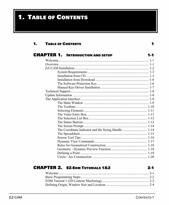
1. TABLE OF CONTENTS 1
CHAPTER 1. INTRODUCTION AND SETUP 1-1 Welcome........................................................................................................... 1-1 Overview .......................................................................................................... 1-1 EZ-CAM Installation........................................................................................ 1-2
System Requirements......................................................................... 1-3 Installation from CD .......................................................................... 1-3 Installation from Download ............................................................... 1-6 The Software Protection Key ............................................................. 1-6 Manual Key-Driver Installation ......................................................... 1-7
Technical Support............................................................................................. 1-8 Update Information .......................................................................................... 1-8 The Application Interface................................................................................. 1-9
The Main Window ............................................................................. 1-9 The Toolbars .................................................................................... 1-10 Selecting Elements ........................................................................... 1-11 The Value Entry Box........................................................................ 1-11 The Selection List Box..................................................................... 1-12 The Status Buttons ........................................................................... 1-12 The Screen Prompt ........................................................................... 1-14 The Coordinate Indicator and the Sizing Handle ............................. 1-14 The Spreadsheet ............................................................................... 1-15 Screen Tool Tips .............................................................................. 1-16 Dynamic View Commands .............................................................. 1-17 Rules for Geometrical Construction................................................. 1-18 Geometry - Dynamic Preview Function........................................... 1-18 Defining a Point ............................................................................... 1-19 Circle / Arc Construction ................................................................. 1-20
CHAPTER 2. EZ-EDM TUTORIALS 1&2 2-1 Welcome........................................................................................................... 2-1 Basic Programming Steps................................................................................. 2-2 EDM Tutorial 1 (2D Contour Machining)........................................................ 2-2 Defining Origin, Window Size and Location ................................................... 2-4
1. TABLE OF CONTENTS
TABLE OF CONTENTS
CONTENTS-2 EZ-CAM
Setting Preferences ........................................................................................... 2-5 The Part Geometry ........................................................................................... 2-7 Creating Circles ................................................................................................ 2-7 Creating Connected Lines ................................................................................ 2-8 Creating Lines at Angle.................................................................................. 2-10 Trimming of Elements.................................................................................... 2-12 Creating Parallel Lines ................................................................................... 2-13 Creating Line, Two Points.............................................................................. 2-14 Copy / Mirror Geometry................................................................................. 2-16 Deleting Elements .......................................................................................... 2-18 Creating Line, Two Points.............................................................................. 2-20 Creating Circle to simulate Start Point ........................................................... 2-21 The Path Curves ............................................................................................. 2-22 Create the Path Curve (Tutorial 1).................................................................. 2-22 Defining Start / Endpoint................................................................................ 2-24 Creating the Part Program .............................................................................. 2-26 Creating Work Step #1 (Contouring + Stop) ................................................. 2-27 Creating Work Step #2 (Cut-Off) .................................................................. 2-32 3D Solid Preview............................................................................................ 2-35 Saving the Part................................................................................................ 2-37 Creating CNC Code........................................................................................ 2-39 EDM Tutorial 2 (XYUV Machining) ............................................................. 2-42 Defining Origin, Window Size and Location ................................................. 2-43 Setting Preferences ......................................................................................... 2-44 The Part Geometry ......................................................................................... 2-46 Creating Line, Two Points.............................................................................. 2-46 Copy / Rotating Geometry.............................................................................. 2-47 Inserting Corner Fillets................................................................................... 2-49 Creating Circle ............................................................................................... 2-50 Adding Line to match Start of XY and UV Profiles....................................... 2-51 Matching Points of XY and UV Contours...................................................... 2-52 Create Matching Lines ................................................................................... 2-52 Copy / Rotating Geometry.............................................................................. 2-53 Trimming of Elements.................................................................................... 2-55 Create XY Path Curve (Lower Contour) ........................................................ 2-56 Defining Start/End for XY Curve................................................................... 2-58 Create UV Path Curve (Upper Contour) ........................................................ 2-59 Defining Start/End for UV Curve................................................................... 2-61 Moving UV Upper Contour Curve ................................................................. 2-62 Creating the Part Program .............................................................................. 2-65 Creating the XYUV Machining Work Step.................................................... 2-65 Verifying the XYUV Wire Path ..................................................................... 2-70 3D Solid Preview............................................................................................ 2-71 Saving the Part................................................................................................ 2-72
TABLE OF CONTENTS
EZ-CAM CONTENTS-3
Creating CNC Code........................................................................................ 2-73
CHAPTER 3. COMMUNICATION WITH THE CONTROL 3-1 Communication with the Control ..................................................................... 3-1 Cable Diagrams ................................................................................................ 3-4
Cable Layout 1: XON /XOFF Software Handshake (Fanuc)............. 3-4 Cable Layout 2: RTS /CTS Hardware Handshake (Heidenhain) ....... 3-5 Cable Layout 3: Universal (XON/XOFF and/or RTS/CTS) .............. 3-6
EZ-CAM 1-1
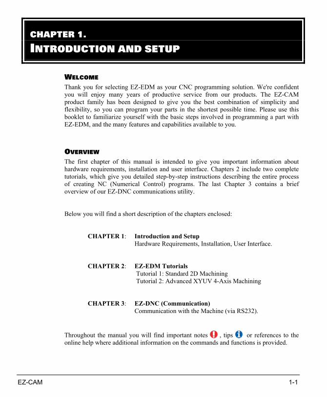
WELCOME Thank you for selecting EZ-EDM as your CNC programming solution. We're confident you will enjoy many years of productive service from our products. The EZ-CAM product family has been designed to give you the best combination of simplicity and flexibility, so you can program your parts in the shortest possible time. Please use this booklet to familiarize yourself with the basic steps involved in programming a part with EZ-EDM, and the many features and capabilities available to you.
OVERVIEW The first chapter of this manual is intended to give you important information about hardware requirements, installation and user interface. Chapters 2 include two complete tutorials, which give you detailed step-by-step instructions describing the entire process of creating NC (Numerical Control) programs. The last Chapter 3 contains a brief overview of our EZ-DNC communications utility. Below you will find a short description of the chapters enclosed:
CHAPTER 1: Introduction and Setup Hardware Requirements, Installation, User Interface.
CHAPTER 2: EZ-EDM Tutorials
Tutorial 1: Standard 2D Machining Tutorial 2: Advanced XYUV 4-Axis Machining
CHAPTER 3: EZ-DNC (Communication)
Communication with the Machine (via RS232). Throughout the manual you will find important notes , tips or references to the online help where additional information on the commands and functions is provided.
CHAPTER 1. INTRODUCTION AND SETUP
CHAPTER 1
1-2 EZ-CAM
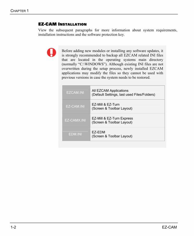
EZ-CAM INSTALLATION View the subsequent paragraphs for more information about system requirements, installation instructions and the software protection key.
Before adding new modules or installing any software updates, it is strongly recommended to backup all EZCAM related INI files that are located in the operating systems main directory (normally “C:\WINDOWS”). Although existing INI files are not overwritten during the setup process, newly installed EZCAM applications may modify the files so they cannot be used with previous versions in case the system needs to be restored.
EZCAM.INI All EZCAM Applications (Default Settings, last used Files/Folders)
EZ-CAM.INI EZ-Mill & EZ-Turn (Screen & Toolbar Layout)
EZ-CAMX.INI EZ-Mill & EZ-Turn Express (Screen & Toolbar Layout)
EDM.INI EZ-EDM (Screen & Toolbar Layout)
INTRODUCTION AND SETUP
EZ-CAM 1-3
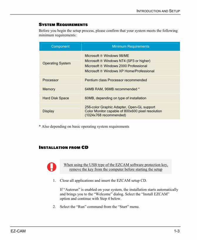
SYSTEM REQUIREMENTS Before you begin the setup process, please confirm that your system meets the following minimum requirements:
Component Minimum Requirements
Operating System
Microsoft Windows 98/ME
Microsoft Windows NT4 (SP3 or higher)
Microsoft Windows 2000 Professional
Microsoft Windows XP Home/Professional
Processor Pentium class Processor recommended
Memory 64MB RAM, 96MB recommended *
Hard Disk Space 60MB, depending on type of installation
Display 256-color Graphic Adapter, Open-GL support Color Monitor capable of 800x600 pixel resolution (1024x768 recommended)
* Also depending on basic operating system requirements
INSTALLATION FROM CD
When using the USB type of the EZCAM software protection key,
remove the key from the computer before starting the setup
1. Close all applications and insert the EZCAM setup CD.
If “Autorun” is enabled on your system, the installation starts automatically and brings you to the “Welcome” dialog. Select the “Install EZCAM” option and continue with Step 4 below.
2. Select the “Run” command from the “Start” menu.
CHAPTER 1
1-4 EZ-CAM
3. Type “D:\setup” (substitute the appropriate letter of your CD-ROM drive
for D) and select “OK” to start the installation routine.
4. Once you agreed to the “License Agreement” you’ll come to the dialog that defines the destination folder (default “EZCAMW”). Continue pressing “Next”.
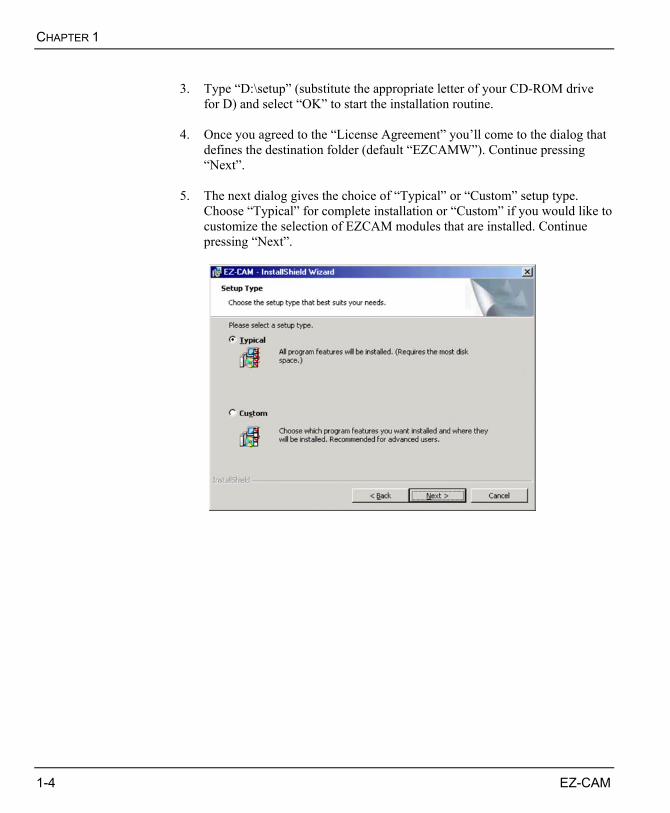
5. The next dialog gives the choice of “Typical” or “Custom” setup type.
Choose “Typical” for complete installation or “Custom” if you would like to customize the selection of EZCAM modules that are installed. Continue pressing “Next”.
INTRODUCTION AND SETUP
EZ-CAM 1-5
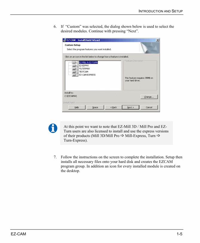
6. If “Custom” was selected, the dialog shown below is used to select the
desired modules. Continue with pressing “Next”.
At this point we want to note that EZ-Mill 3D / Mill Pro and EZ-Turn users are also licensed to install and use the express versions of their products (Mill 3D/Mill Pro Mill-Express, Turn Turn-Express).
7. Follow the instructions on the screen to complete the installation. Setup then
installs all necessary files onto your hard disk and creates the EZCAM program group. In addition an icon for every installed module is created on the desktop.
CHAPTER 1
1-6 EZ-CAM
INSTALLATION FROM DOWNLOAD For the download version of the setup, EZCAM provides separate files for MILL&TURN and EDM in order to save download time.
1. Copy the downloaded file to a temporary folder.
2. Start the setup by double-clicking the file.
3. Follow the setup instructions.
The online-help system and tutorial files are not included in the setup. They are available as separate downloads.
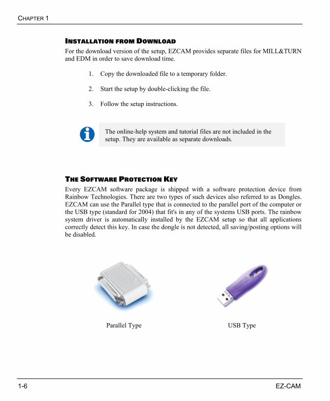
THE SOFTWARE PROTECTION KEY Every EZCAM software package is shipped with a software protection device from Rainbow Technologies. There are two types of such devices also referred to as Dongles. EZCAM can use the Parallel type that is connected to the parallel port of the computer or the USB type (standard for 2004) that fit's in any of the systems USB ports. The rainbow system driver is automatically installed by the EZCAM setup so that all applications correctly detect this key. In case the dongle is not detected, all saving/posting options will be disabled.
Parallel Type USB Type
INTRODUCTION AND SETUP
EZ-CAM 1-7
• The rainbow system driver is automatically installed by the
EZCAM setup. Manual driver installation for all rainbow key types is only necessary in case the automatic driver installation during the EZCAM setup fails !
• USB keys are currently only supported on Windows 9x, ME, 2000 and XP systems. Windows NT does not support USB devices.
MANUAL KEY-DRIVER INSTALLATION As mentioned previously, manual driver installation is only necessary in case the automatic installation fails or a driver update is required.
• Remember that you have to log in using an account with
administrator privileges to install software drivers under Windows NT / 2000 / XP.
• USB keys are currently only supported on Windows 9x, ME, 2000 and XP systems. Windows NT does not support USB devices.
• When using the USB key type, remove the key from the computer before starting the driver setup.
Procedure:
1. Start Windows Explorer.
2. Navigate to the ‘Rainbow’ folder located in the EZCAM installation directory.
3. Double-click ‘Setup.exe’ to start the Rainbow Technologies Setup.
4. Select the ‘Complete’ installation and click "Next" to continue.
5. Finally select the ‘Finish’ button to exit Setup. If you are running Windows 98/ME, you will have to reboot the system to start the parallel driver. Windows NT , 2000 or XP do not require a reboot.
CHAPTER 1
1-8 EZ-CAM
TECHNICAL SUPPORT Software purchased directly from EZCAM Solutions Inc. includes 1 year of technical support and maintenance.
As our technical staff uses current versions of the product it is highly recommended that you upgrade when new major releases, fixes or incremental patch updates become available. Only then, we can guarantee that our application expertise in the form of example files, posts, etc. can be applied without any incompatibilities. Therefore we suggest to periodically check the download area at www.ezcam.com for new updates and patches, especially before calling support. As such files are normally provided in compressed (ZIP) format, download and save the zip file to your system. Then open it and view the readme file for further instructions.
UPDATE INFORMATION
As with any software purchase, to get the most out of your investment and to ensure the years of trouble free service and support, it is highly recommended that you upgrade when new major releases become available. As EZCAM enhances the software, all registered users will be notified by mail of software updates. Updated software will be available to registered users at special low prices. You can visit EZ-CAM’s web site at at www.ezcam.com to download latest fixes and new versions.
INTRODUCTION AND SETUP
EZ-CAM 1-9
THE APPLICATION INTERFACE The following paragraphs are intended to give an overview of the application interface with all its toolbars, list boxes, and command buttons together with some general rules for geometry construction.
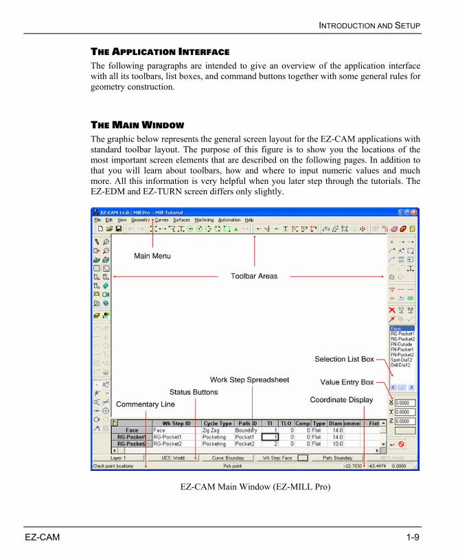
THE MAIN WINDOW The graphic below represents the general screen layout for the EZ-CAM applications with standard toolbar layout. The purpose of this figure is to show you the locations of the most important screen elements that are described on the following pages. In addition to that you will learn about toolbars, how and where to input numeric values and much more. All this information is very helpful when you later step through the tutorials. The EZ-EDM and EZ-TURN screen differs only slightly.
EZ-CAM Main Window (EZ-MILL Pro)
CHAPTER 1
1-10 EZ-CAM
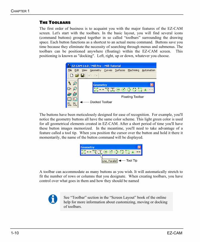
THE TOOLBARS The first order of business is to acquaint you with the major features of the EZ-CAM screen. Let's start with the toolbars. In the basic layout, you will find several icons (command buttons) grouped together in so called “toolbars” surrounding the drawing space. Each button functions as a shortcut to an actual menu command. Buttons save you time because they eliminate the necessity of searching through menus and submenus. The toolbars can be positioned anywhere (floating) within the EZ-CAM screen. This positioning is known as "docking". Left, right, up or down, whatever you choose.
The buttons have been meticulously designed for ease of recognition. For example, you'll notice the geometry buttons all have the same color scheme. This light green color is used for all geometrical elements created in EZ-CAM. After a short period of time you'll have these button images memorized. In the meantime, you'll need to take advantage of a feature called a tool tip. When you position the cursor over the button and hold it there it momentarily, the name of the button command will be displayed.
A toolbar can accommodate as many buttons as you wish. It will automatically stretch to fit the number of rows or columns that you designate. When creating toolbars, you have control over what goes in them and how they should be named
See “Toolbar” section in the “Screen Layout” book of the online help for more information about customizing, moving or docking of toolbars.
INTRODUCTION AND SETUP
EZ-CAM 1-11
SELECTING ELEMENTS Whenever you want to perform an action on one or more elements (geometry, path, etc.), you have to select them prior to execution of the function. For example, if you want to delete an entity from the view port, you must first click the Delete button and then select the desired entity. This can be done by selecting (click) each single element using the cursor or by placing a selection box (rectangle) around all the desired elements. Only the ones that are entirely enclosed in this box are selected and displayed in a dotted style. If you select the wrong one just click on this element again and it’s deselected.
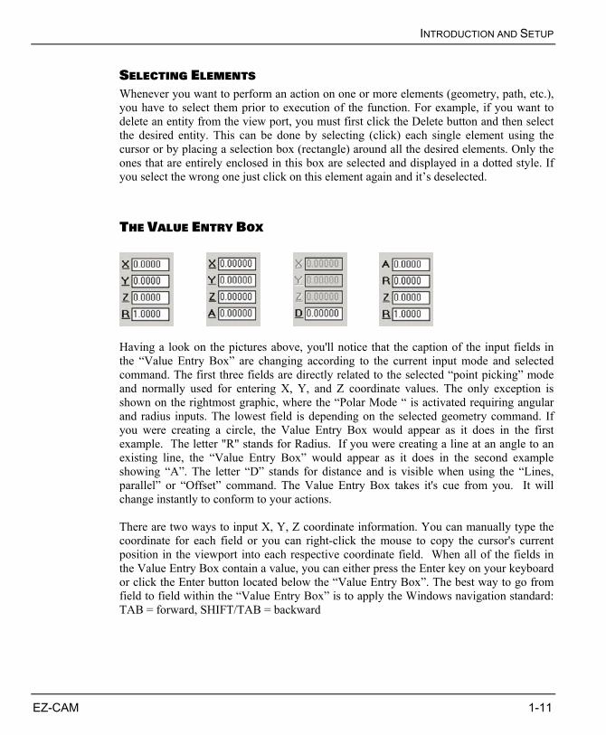
THE VALUE ENTRY BOX
Having a look on the pictures above, you'll notice that the caption of the input fields in the “Value Entry Box” are changing according to the current input mode and selected command. The first three fields are directly related to the selected “point picking” mode and normally used for entering X, Y, and Z coordinate values. The only exception is shown on the rightmost graphic, where the “Polar Mode “ is activated requiring angular and radius inputs. The lowest field is depending on the selected geometry command. If you were creating a circle, the Value Entry Box would appear as it does in the first example. The letter "R" stands for Radius. If you were creating a line at an angle to an existing line, the “Value Entry Box” would appear as it does in the second example showing “A”. The letter “D” stands for distance and is visible when using the “Lines, parallel” or “Offset” command. The Value Entry Box takes it's cue from you. It will change instantly to conform to your actions. There are two ways to input X, Y, Z coordinate information. You can manually type the coordinate for each field or you can right-click the mouse to copy the cursor's current position in the viewport into each respective coordinate field. When all of the fields in the Value Entry Box contain a value, you can either press the Enter key on your keyboard or click the Enter button located below the “Value Entry Box”. The best way to go from field to field within the “Value Entry Box” is to apply the Windows navigation standard: TAB = forward, SHIFT/TAB = backward
CHAPTER 1
1-12 EZ-CAM
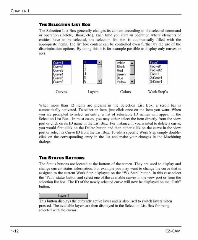
THE SELECTION LIST BOX The Selection List Box generally changes its content according to the selected command or operation (Delete, Blank, etc.). Each time you start an operation where elements or entities have to be selected, the selection list box is automatically filled with the appropriate items. The list box content can be controlled even further by the use of the discrimination options. By doing this it is for example possible to display only curves or arcs.
Curves
Layers Colors Work Step’s
When more than 12 items are present in the Selection List Box, a scroll bar is automatically activated. To select an item, just click once on the item you want. When you are prompted to select an entity, a list of selectable ID names will appear in the Selection List Box. In most cases, you may either select the item directly from the view port or click on its ID name in the List Box. For instance, if you wanted to delete a curve, you would first click on the Delete button and then either click on the curve in the view port or select its Curve ID from the List Box. To edit a specific Work Step simply double-click on the corresponding entry in the list and make your changes in the Machining dialogs.
THE STATUS BUTTONS The Status buttons are located at the bottom of the screen. They are used to display and change current status information. For example you may want to change the curve that is assigned to the current Work Step displayed on the “Wk Step” button. In this case select the “Path” status button and select one of the available curves in the view port or from the selection list box. The ID of the newly selected curve will now be displayed on the “Path” button.
This button displays the currently active layer and is also used to switch layers when pressed. The available layers are then displayed in the Selection List Box for being selected with the cursor.
INTRODUCTION AND SETUP
EZ-CAM 1-13
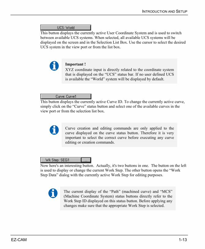
This button displays the currently active User Coordinate System and is used to switch between available UCS systems. When selected, all available UCS systems will be displayed on the screen and in the Selection List Box. Use the cursor to select the desired UCS system in the view port or from the list box.
Important ! XYZ coordinate input is directly related to the coordinate system that is displayed on the “UCS” status bar. If no user defined UCS is available the “World” system will be displayed by default.
This button displays the currently active Curve ID. To change the currently active curve, simply click on the “Curve” status button and select one of the available curves in the view port or from the selection list box.
Curve creation and editing commands are only applied to the curve displayed on the curve status button. Therefore it is very important to select the correct curve before executing any curve editing or creation commands.
Now here's an interesting button. Actually, it's two buttons in one. The button on the left is used to display or change the current Work Step. The other button opens the “Work Step Data” dialog with the currently active Work Step for editing purposes.
The current display of the “Path” (machined curve) and “MCS” (Machine Coordinate System) status buttons directly refer to the Work Step ID displayed on this status button. Before applying any changes make sure that the appropriate Work Step is selected.
CHAPTER 1
1-14 EZ-CAM
This button is used to display and change the curve (path) that is assigned to the currently active Work Step that is shown on the “Wk Step” button.
This button is used to display and change the Machine Coordinate System that is assigned to the currently active Work Step that is shown on the “Wk Step” button.
THE SCREEN PROMPT The screen prompt is located at the very bottom of the screen. You'll find it necessary to refer to the prompt when working.
Here's a condensed version of the screen prompt. In this example, a line using the “Line, two Points” command is being created. The left-hand portion of the screen prompt tells you the purpose of the button or menu command. The right-hand portion of the prompt tells you what to do. In this example, once the first point has been picked or entered, the prompt will give more instructions for the second point.
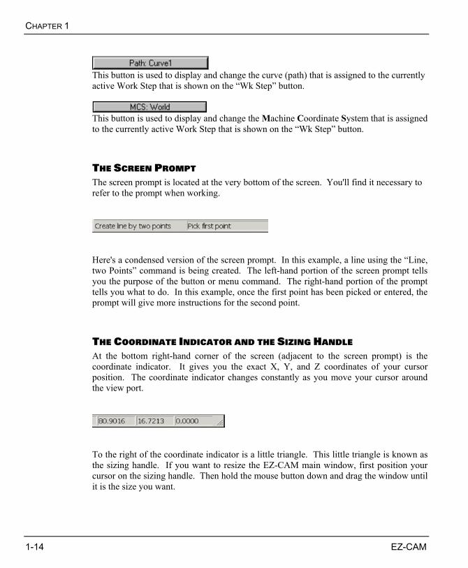
THE COORDINATE INDICATOR AND THE SIZING HANDLE At the bottom right-hand corner of the screen (adjacent to the screen prompt) is the coordinate indicator. It gives you the exact X, Y, and Z coordinates of your cursor position. The coordinate indicator changes constantly as you move your cursor around the view port.
To the right of the coordinate indicator is a little triangle. This little triangle is known as the sizing handle. If you want to resize the EZ-CAM main window, first position your cursor on the sizing handle. Then hold the mouse button down and drag the window until it is the size you want.
INTRODUCTION AND SETUP
EZ-CAM 1-15
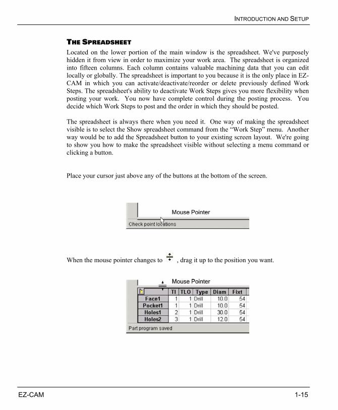
THE SPREADSHEET Located on the lower portion of the main window is the spreadsheet. We've purposely hidden it from view in order to maximize your work area. The spreadsheet is organized into fifteen columns. Each column contains valuable machining data that you can edit locally or globally. The spreadsheet is important to you because it is the only place in EZ-CAM in which you can activate/deactivate/reorder or delete previously defined Work Steps. The spreadsheet's ability to deactivate Work Steps gives you more flexibility when posting your work. You now have complete control during the posting process. You decide which Work Steps to post and the order in which they should be posted. The spreadsheet is always there when you need it. One way of making the spreadsheet visible is to select the Show spreadsheet command from the “Work Step” menu. Another way would be to add the Spreadsheet button to your existing screen layout. We're going to show you how to make the spreadsheet visible without selecting a menu command or clicking a button. Place your cursor just above any of the buttons at the bottom of the screen.
When the mouse pointer changes to , drag it up to the position you want.
CHAPTER 1
1-16 EZ-CAM
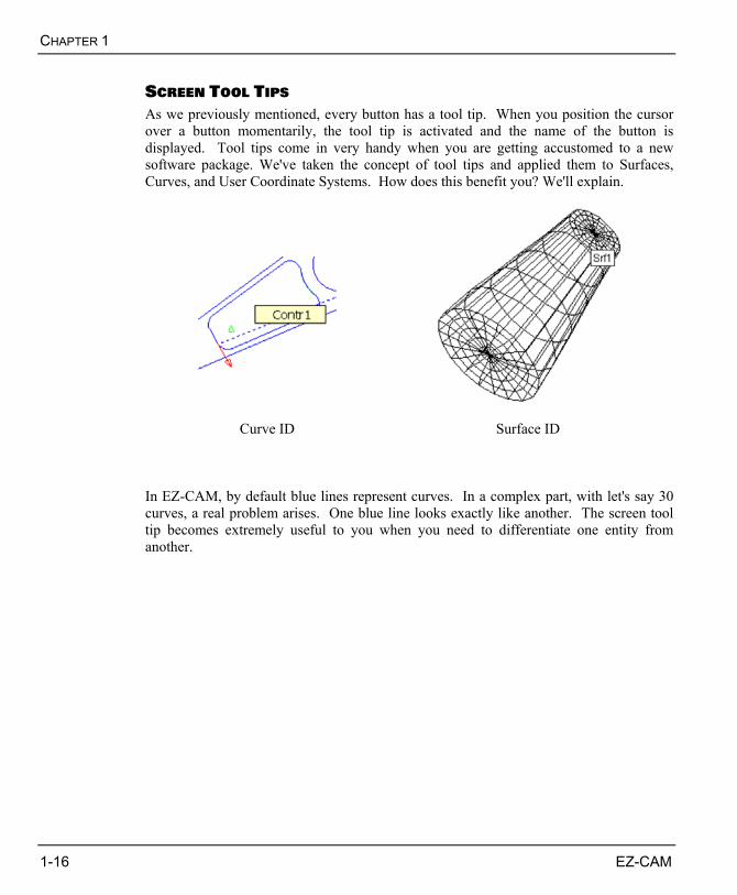
SCREEN TOOL TIPS As we previously mentioned, every button has a tool tip. When you position the cursor over a button momentarily, the tool tip is activated and the name of the button is displayed. Tool tips come in very handy when you are getting accustomed to a new software package. We've taken the concept of tool tips and applied them to Surfaces, Curves, and User Coordinate Systems. How does this benefit you? We'll explain.
Curve ID
Surface ID
In EZ-CAM, by default blue lines represent curves. In a complex part, with let's say 30 curves, a real problem arises. One blue line looks exactly like another. The screen tool tip becomes extremely useful to you when you need to differentiate one entity from another.
INTRODUCTION AND SETUP
EZ-CAM 1-17
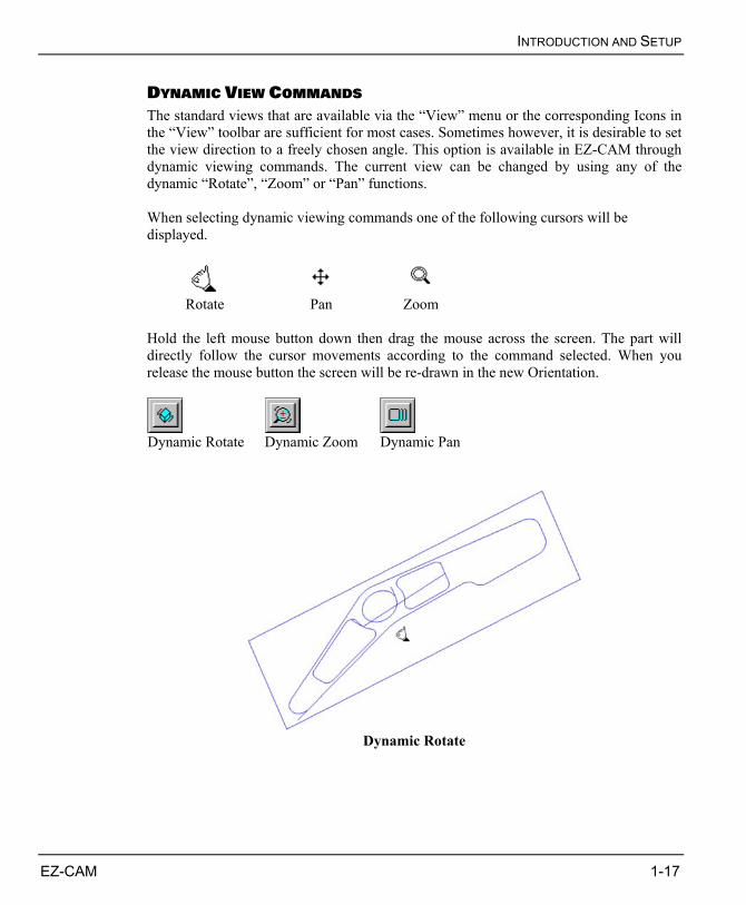
DYNAMIC VIEW COMMANDS The standard views that are available via the “View” menu or the corresponding Icons in the “View” toolbar are sufficient for most cases. Sometimes however, it is desirable to set the view direction to a freely chosen angle. This option is available in EZ-CAM through dynamic viewing commands. The current view can be changed by using any of the dynamic “Rotate”, “Zoom” or “Pan” functions. When selecting dynamic viewing commands one of the following cursors will be displayed.
Rotate Pan Zoom
Hold the left mouse button down then drag the mouse across the screen. The part will directly follow the cursor movements according to the command selected. When you release the mouse button the screen will be re-drawn in the new Orientation.
Dynamic Rotate Dynamic Zoom Dynamic Pan
Dynamic Rotate
CHAPTER 1
1-18 EZ-CAM
RULES FOR GEOMETRICAL CONSTRUCTION Geometry is always based on the currently active coordinate system (World or User defined coordinate system, also referred to as UCS). When several alternative solutions to a construction exist, moving the screen cursor will show the alternative that lies closest to the cursor position in white. When the correct solution is shown, a click with the left-hand mouse button will carry out the construction (this function is called dynamic preview).
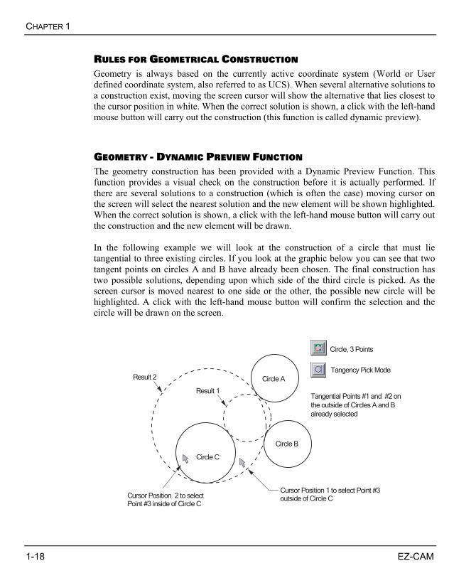
GEOMETRY - DYNAMIC PREVIEW FUNCTION The geometry construction has been provided with a Dynamic Preview Function. This function provides a visual check on the construction before it is actually performed. If there are several solutions to a construction (which is often the case) moving cursor on the screen will select the nearest solution and the new element will be shown highlighted. When the correct solution is shown, a click with the left-hand mouse button will carry out the construction and the new element will be drawn. In the following example we will look at the construction of a circle that must lie tangential to three existing circles. If you look at the graphic below you can see that two tangent points on circles A and B have already been chosen. The final construction has two possible solutions, depending upon which side of the third circle is picked. As the screen cursor is moved nearest to one side or the other, the possible new circle will be highlighted. A click with the left-hand mouse button will confirm the selection and the circle will be drawn on the screen.
Tangential Points #1 and #2 on
the outside of Circles A and B
already selected
Cursor Position 1 to select Point #3outside of Circle C
Circle A
Circle B
Circle C
Cursor Position 2 to selectPoint #3 inside of Circle C
Result 2
Result 1
Circle, 3 Points
Tangency Pick Mode
INTRODUCTION AND SETUP
EZ-CAM 1-19
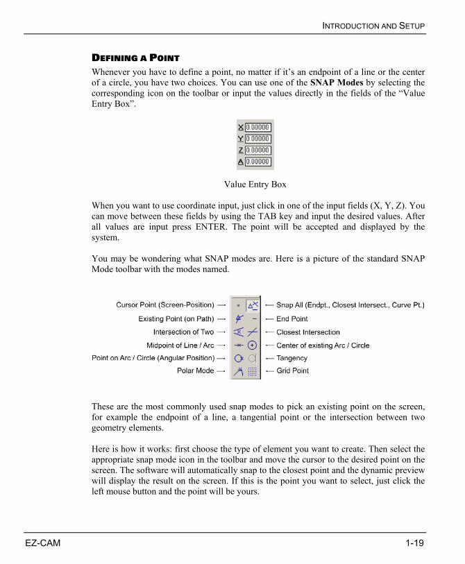
DEFINING A POINT Whenever you have to define a point, no matter if it’s an endpoint of a line or the center of a circle, you have two choices. You can use one of the SNAP Modes by selecting the corresponding icon on the toolbar or input the values directly in the fields of the “Value Entry Box”.
Value Entry Box When you want to use coordinate input, just click in one of the input fields (X, Y, Z). You can move between these fields by using the TAB key and input the desired values. After all values are input press ENTER. The point will be accepted and displayed by the system. You may be wondering what SNAP modes are. Here is a picture of the standard SNAP Mode toolbar with the modes named.
These are the most commonly used snap modes to pick an existing point on the screen, for example the endpoint of a line, a tangential point or the intersection between two geometry elements. Here is how it works: first choose the type of element you want to create. Then select the appropriate snap mode icon in the toolbar and move the cursor to the desired point on the screen. The software will automatically snap to the closest point and the dynamic preview will display the result on the screen. If this is the point you want to select, just click the left mouse button and the point will be yours.
CHAPTER 1
1-20 EZ-CAM
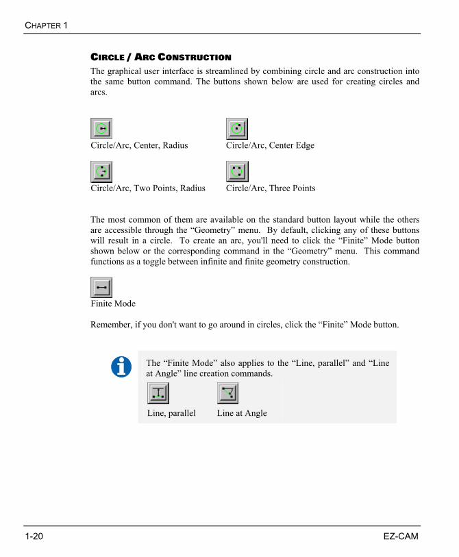
CIRCLE / ARC CONSTRUCTION The graphical user interface is streamlined by combining circle and arc construction into the same button command. The buttons shown below are used for creating circles and arcs.
Circle/Arc, Center, Radius Circle/Arc, Center Edge
Circle/Arc, Two Points, Radius Circle/Arc, Three Points The most common of them are available on the standard button layout while the others are accessible through the “Geometry” menu. By default, clicking any of these buttons will result in a circle. To create an arc, you'll need to click the “Finite” Mode button shown below or the corresponding command in the “Geometry” menu. This command functions as a toggle between infinite and finite geometry construction.
Finite Mode Remember, if you don't want to go around in circles, click the “Finite” Mode button.
The “Finite Mode” also applies to the “Line, parallel” and “Line at Angle” line creation commands.
Line, parallel Line at Angle
EZ-CAM 2-1
WELCOME This chapter is an instructional guide intended for users with little or no experience in EZ-EDM operations. The two exercises in this chapter step through the entire process of creating NC programs for the sample parts.
EDM Tutorial 1: Standard 2D Machining EDM Tutorial 2: Advanced 4-Axis Machining
Throughout the tutorial you will find important notes , tips or references to the online help where additional information on the commands and functions is provided. The following steps are explained in detail:
• Geometry creation in EZ-EDM • Create the path curves • Create the Part program (define Work Steps to machine the part) • Posting the NC code
CHAPTER 2. EZ-EDM TUTORIALS 1&2
CHAPTER 2
2-2 EZ-CAM
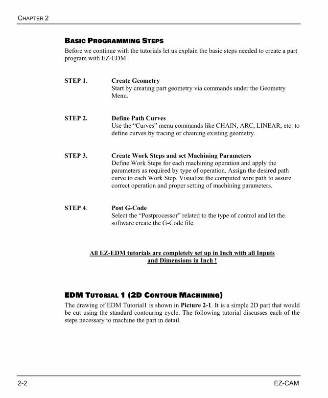
BASIC PROGRAMMING STEPS Before we continue with the tutorials let us explain the basic steps needed to create a part program with EZ-EDM. STEP 1. Create Geometry
Start by creating part geometry via commands under the Geometry Menu.
STEP 2. Define Path Curves
Use the “Curves” menu commands like CHAIN, ARC, LINEAR, etc. to define curves by tracing or chaining existing geometry.
STEP 3. Create Work Steps and set Machining Parameters
Define Work Steps for each machining operation and apply the parameters as required by type of operation. Assign the desired path curve to each Work Step. Visualize the computed wire path to assure correct operation and proper setting of machining parameters.
STEP 4. Post G-Code
Select the “Postprocessor” related to the type of control and let the software create the G-Code file.
All EZ-EDM tutorials are completely set up in Inch with all Inputs and Dimensions in Inch !
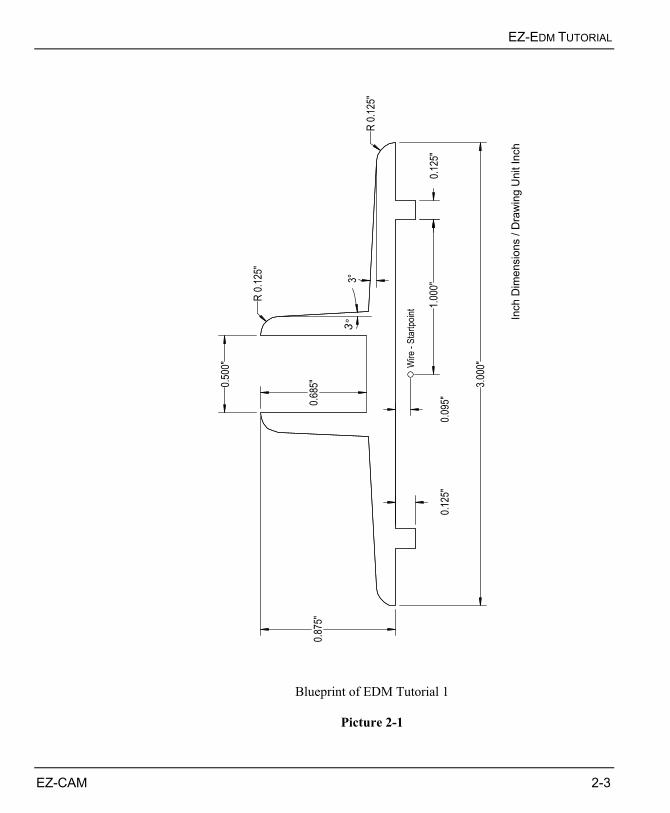
EDM TUTORIAL 1 (2D CONTOUR MACHINING) The drawing of EDM Tutorial1 is shown in Picture 2-1. It is a simple 2D part that would be cut using the standard contouring cycle. The following tutorial discusses each of the steps necessary to machine the part in detail.
EZ-EDM TUTORIAL
EZ-CAM 2-3
3°
Wire
- St
artp
oint
Inch
Dim
ensi
ons
/ Dra
win
g U
nit I
nch
3.00
0"
0.50
0"
0.12
5"1.
000"
0.87
5"
0.12
5"
R 0.
125"
R 0.
125"
3°
0.68
5"
0.09
5"
Blueprint of EDM Tutorial 1
Picture 2-1
CHAPTER 2
2-4 EZ-CAM
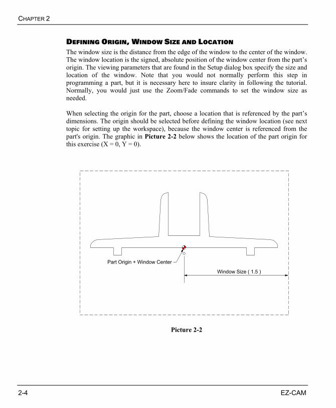
DEFINING ORIGIN, WINDOW SIZE AND LOCATION The window size is the distance from the edge of the window to the center of the window. The window location is the signed, absolute position of the window center from the part’s origin. The viewing parameters that are found in the Setup dialog box specify the size and location of the window. Note that you would not normally perform this step in programming a part, but it is necessary here to insure clarity in following the tutorial. Normally, you would just use the Zoom/Fade commands to set the window size as needed. When selecting the origin for the part, choose a location that is referenced by the part’s dimensions. The origin should be selected before defining the window location (see next topic for setting up the workspace), because the window center is referenced from the part's origin. The graphic in Picture 2-2 below shows the location of the part origin for this exercise (X = 0, Y = 0).
Window Size ( 1.5 )
Part Origin + Window Center
Picture 2-2
EZ-EDM TUTORIAL
EZ-CAM 2-5
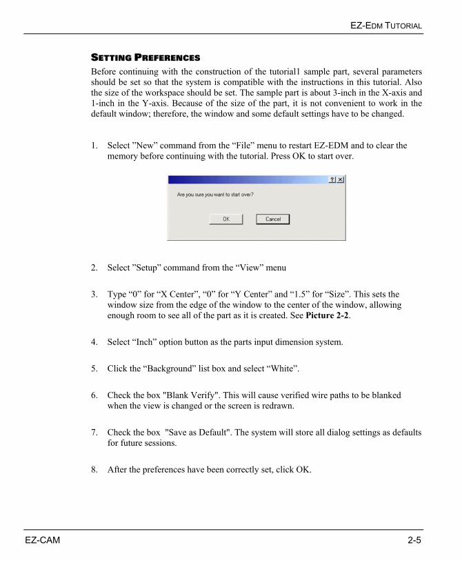
SETTING PREFERENCES Before continuing with the construction of the tutorial1 sample part, several parameters should be set so that the system is compatible with the instructions in this tutorial. Also the size of the workspace should be set. The sample part is about 3-inch in the X-axis and 1-inch in the Y-axis. Because of the size of the part, it is not convenient to work in the default window; therefore, the window and some default settings have to be changed. 1. Select ”New” command from the “File” menu to restart EZ-EDM and to clear the
memory before continuing with the tutorial. Press OK to start over.
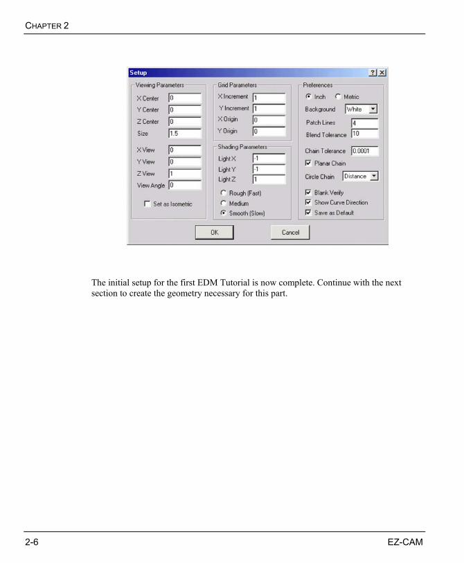
2. Select ”Setup” command from the “View” menu 3. Type “0” for “X Center”, “0” for “Y Center” and “1.5” for “Size”. This sets the
window size from the edge of the window to the center of the window, allowing enough room to see all of the part as it is created. See Picture 2-2.
4. Select “Inch” option button as the parts input dimension system. 5. Click the “Background” list box and select “White”. 6. Check the box "Blank Verify". This will cause verified wire paths to be blanked
when the view is changed or the screen is redrawn. 7. Check the box "Save as Default". The system will store all dialog settings as defaults
for future sessions. 8. After the preferences have been correctly set, click OK.
CHAPTER 2
2-6 EZ-CAM
The initial setup for the first EDM Tutorial is now complete. Continue with the next section to create the geometry necessary for this part.
EZ-EDM TUTORIAL
EZ-CAM 2-7
THE PART GEOMETRY Now that the view port has been adjusted to accommodate the part, the creation of the part can begin. This involves creating geometry that is used to define the wire paths for machining the part. The geometry is created first, so that the process of creating the wire paths is greatly simplified. Part geometry is necessary because it creates guidelines to follow when defining the wire path. The geometry used in this tutorial is fairly simple. It consists mainly of several lines and arcs. There are many ways to create the geometry required for this part. The method chosen for this tutorial demonstrates the use of several tools available within the geometry menu. Since this part is symmetrical across the Y axis, the geometry for one side of the part will be created, and then mirrored across the Y axis to create the other half.
X-Y View If it’s not already the case, click the “X-Y View” button to change the view to X-Y
CREATING CIRCLES 1. Click the “Circle/Arc, Center, Radius” command from the geometry toolbar.
Circle/Arc, Center, Radius
2. For the Radius of the first circle, type “0.125” in the “R” field of the Value Entry
Box. You will see the “preview” circle on the screen when you move the mouse. 3. Use the TAB key to move to the “X” field. Type “1.5 – 0.125” for the Center X
location, then press Tab again to move to Y field. 4. Type “0” for the Center Y location. Then click the ENTER button and the first circle
will be drawn at the desired location.
CHAPTER 2
2-8 EZ-CAM
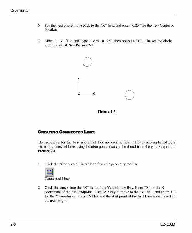
6. For the next circle move back to the “X” field and enter “0.25” for the new Center X
location. 7. Move to “Y” field and Type “0.875 - 0.125”, then press ENTER. The second circle
will be created. See Picture 2-3.
Y
Z X
Picture 2-3
CREATING CONNECTED LINES The geometry for the base and small foot are created next. This is accomplished by a series of connected lines using location points that can be found from the part blueprint in Picture 2-1. 1. Click the “Connected Lines” Icon from the geometry toolbar.
Connected Lines
2. Click the cursor into the “X” field of the Value Entry Box. Enter “0” for the X
coordinate of the first endpoint. Use TAB key to move to the “Y” field and enter “0” for the Y coordinate. Press ENTER and the start point of the first Line is displayed at the axis origin.
EZ-EDM TUTORIAL
EZ-CAM 2-9
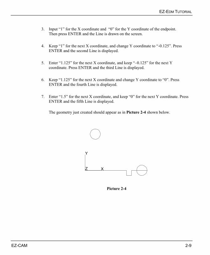
3. Input “1” for the X coordinate and “0” for the Y coordinate of the endpoint.
Then press ENTER and the Line is drawn on the screen. 4. Keep “1” for the next X coordinate, and change Y coordinate to “-0.125”. Press
ENTER and the second Line is displayed. 5. Enter “1.125” for the next X coordinate, and keep “–0.125” for the next Y
coordinate. Press ENTER and the third Line is displayed. 6. Keep “1.125” for the next X coordinate and change Y coordinate to “0”. Press
ENTER and the fourth Line is displayed. 7. Enter “1.5” for the next X coordinate, and keep “0” for the next Y coordinate. Press
ENTER and the fifth Line is displayed.
The geometry just created should appear as in Picture 2-4 shown below.
Y
Z X
Picture 2-4
CHAPTER 2
2-10 EZ-CAM
CREATING LINES AT ANGLE The next step in creating the geometry is to define the angled lines at the outer edge of the part. These lines are created tangent to the already existing circles. 1. Select the “Line at Angle” command from the Geometry toolbar. This command
creates a Line at a specified angle to a selected Line, and through a selected point. In this case the selected Line will be the Y axis, and the point is the tangency point on the circle.
Line at Angle
2. Move the cursor to the Y axis of the coordinate system until the dynamic preview
will display a Line on the Y axis. Then click with the left mouse button. This will select the Y axis as reference axis for the angular input.
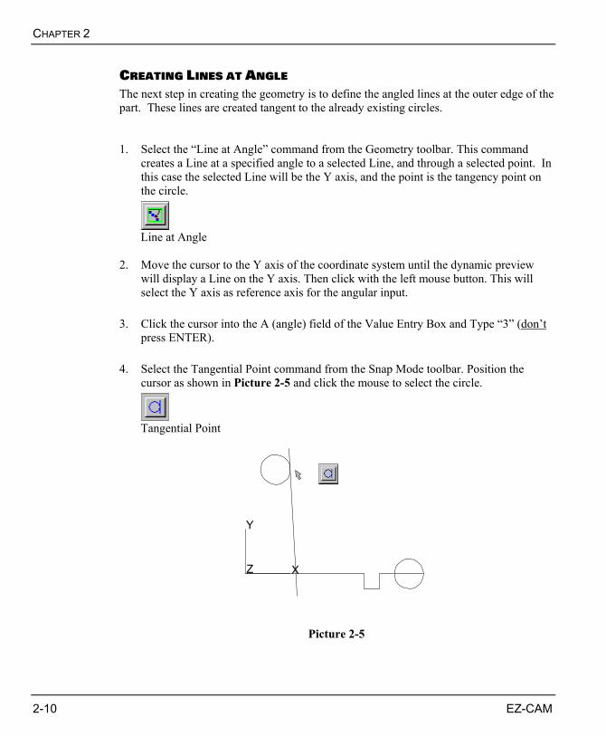
3. Click the cursor into the A (angle) field of the Value Entry Box and Type “3” (don’t
press ENTER). 4. Select the Tangential Point command from the Snap Mode toolbar. Position the
cursor as shown in Picture 2-5 and click the mouse to select the circle.
Tangential Point
Y
Z X
Picture 2-5
EZ-EDM TUTORIAL
EZ-CAM 2-11
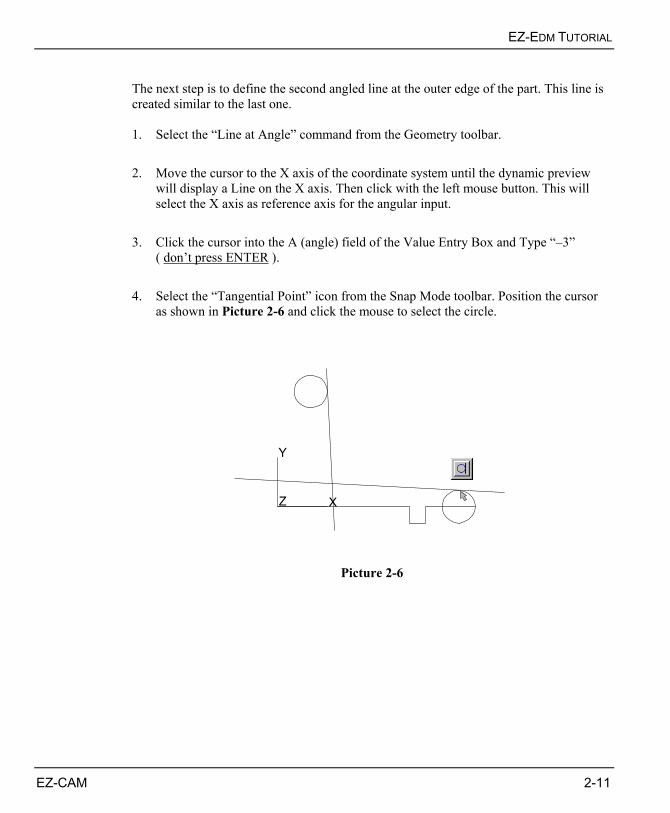
The next step is to define the second angled line at the outer edge of the part. This line is created similar to the last one. 1. Select the “Line at Angle” command from the Geometry toolbar. 2. Move the cursor to the X axis of the coordinate system until the dynamic preview
will display a Line on the X axis. Then click with the left mouse button. This will select the X axis as reference axis for the angular input.
3. Click the cursor into the A (angle) field of the Value Entry Box and Type “–3”
( don’t press ENTER ). 4. Select the “Tangential Point” icon from the Snap Mode toolbar. Position the cursor
as shown in Picture 2-6 and click the mouse to select the circle.
Y
Z X
Picture 2-6
CHAPTER 2
2-12 EZ-CAM
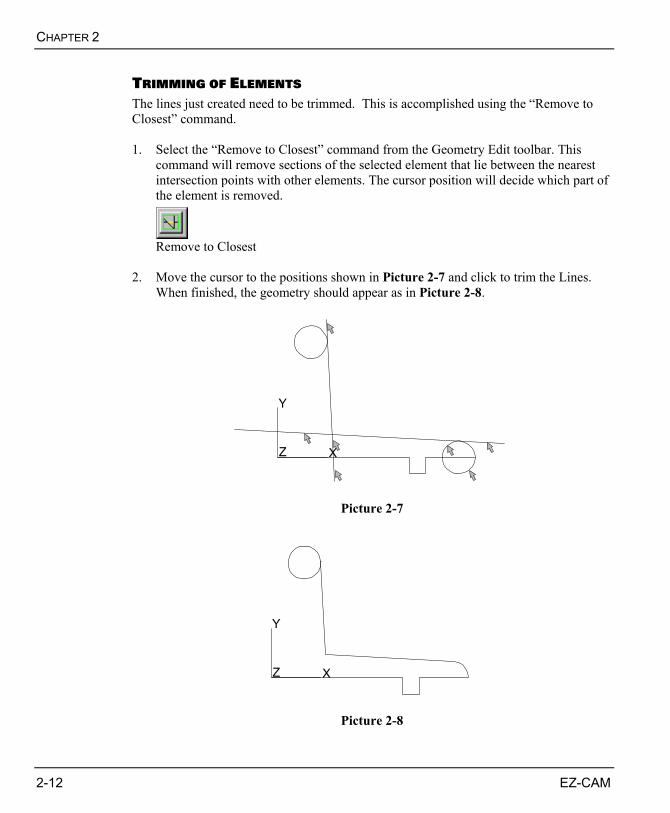
TRIMMING OF ELEMENTS The lines just created need to be trimmed. This is accomplished using the “Remove to Closest” command. 1. Select the “Remove to Closest” command from the Geometry Edit toolbar. This
command will remove sections of the selected element that lie between the nearest intersection points with other elements. The cursor position will decide which part of the element is removed.
Remove to Closest
2. Move the cursor to the positions shown in Picture 2-7 and click to trim the Lines.
When finished, the geometry should appear as in Picture 2-8.
Y
Z X
Picture 2-7
Y
Z X
Picture 2-8
EZ-EDM TUTORIAL
EZ-CAM 2-13
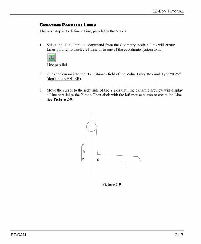
CREATING PARALLEL LINES The next step is to define a Line, parallel to the Y axis. 1. Select the “Line Parallel” command from the Geometry toolbar. This will create
Lines parallel to a selected Line or to one of the coordinate system axis.
Line parallel
2. Click the cursor into the D (Distance) field of the Value Entry Box and Type “0.25”
(don’t press ENTER). 3. Move the cursor to the right side of the Y axis until the dynamic preview will display
a Line parallel to the Y axis. Then click with the left mouse button to create the Line. See Picture 2-9.
Y
Z X
Picture 2-9
CHAPTER 2
2-14 EZ-CAM
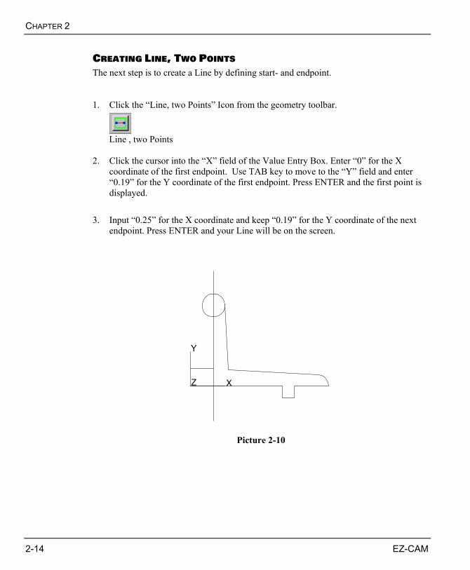
CREATING LINE, TWO POINTS The next step is to create a Line by defining start- and endpoint. 1. Click the “Line, two Points” Icon from the geometry toolbar.
Line , two Points
2. Click the cursor into the “X” field of the Value Entry Box. Enter “0” for the X
coordinate of the first endpoint. Use TAB key to move to the “Y” field and enter “0.19” for the Y coordinate of the first endpoint. Press ENTER and the first point is displayed.
3. Input “0.25” for the X coordinate and keep “0.19” for the Y coordinate of the next
endpoint. Press ENTER and your Line will be on the screen.
Y
Z X
Picture 2-10
EZ-EDM TUTORIAL
EZ-CAM 2-15
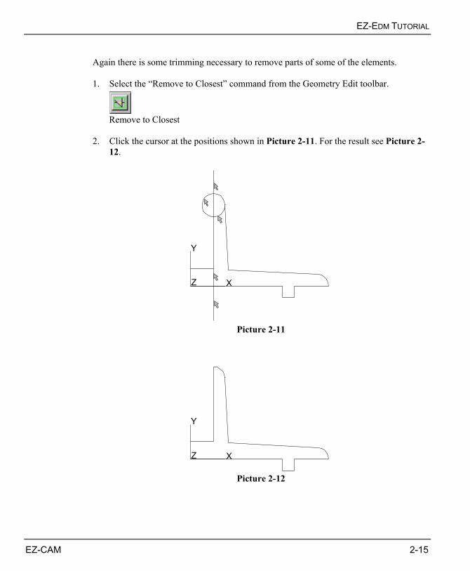
Again there is some trimming necessary to remove parts of some of the elements. 1. Select the “Remove to Closest” command from the Geometry Edit toolbar.
Remove to Closest
2. Click the cursor at the positions shown in Picture 2-11. For the result see Picture 2-
12.
Y
Z X
Picture 2-11
Y
Z X
Picture 2-12
CHAPTER 2
2-16 EZ-CAM
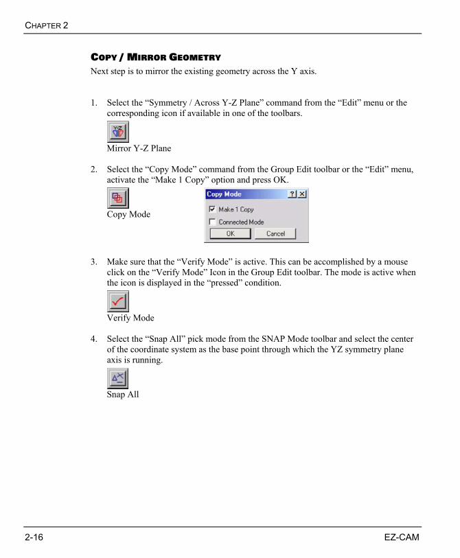
COPY / MIRROR GEOMETRY Next step is to mirror the existing geometry across the Y axis. 1. Select the “Symmetry / Across Y-Z Plane” command from the “Edit” menu or the
corresponding icon if available in one of the toolbars.
Mirror Y-Z Plane
2. Select the “Copy Mode” command from the Group Edit toolbar or the “Edit” menu,
activate the “Make 1 Copy” option and press OK.
Copy Mode
3. Make sure that the “Verify Mode” is active. This can be accomplished by a mouse
click on the “Verify Mode” Icon in the Group Edit toolbar. The mode is active when the icon is displayed in the “pressed” condition.
Verify Mode
4. Select the “Snap All” pick mode from the SNAP Mode toolbar and select the center
of the coordinate system as the base point through which the YZ symmetry plane axis is running.
Snap All
EZ-EDM TUTORIAL
EZ-CAM 2-17
Y
Z X
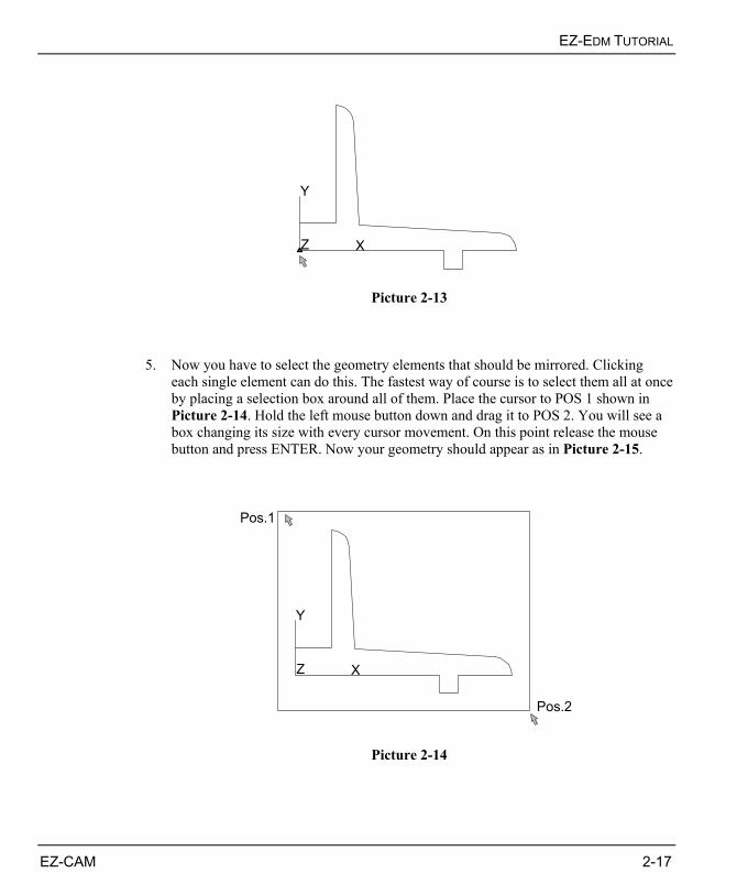
Picture 2-13
5. Now you have to select the geometry elements that should be mirrored. Clicking
each single element can do this. The fastest way of course is to select them all at once by placing a selection box around all of them. Place the cursor to POS 1 shown in Picture 2-14. Hold the left mouse button down and drag it to POS 2. You will see a box changing its size with every cursor movement. On this point release the mouse button and press ENTER. Now your geometry should appear as in Picture 2-15.
Y
Z X
Pos.1
Pos.2
Picture 2-14
CHAPTER 2
2-18 EZ-CAM
Y
Z X
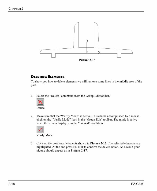
Picture 2-15
DELETING ELEMENTS To show you how to delete elements we will remove some lines in the middle area of the part. 1. Select the “Delete” command from the Group Edit toolbar.
Delete
2. Make sure that the “Verify Mode” is active. This can be accomplished by a mouse
click on the “Verify Mode” Icon in the “Group Edit” toolbar. The mode is active when the icon is displayed in the “pressed” condition.
Verify Mode
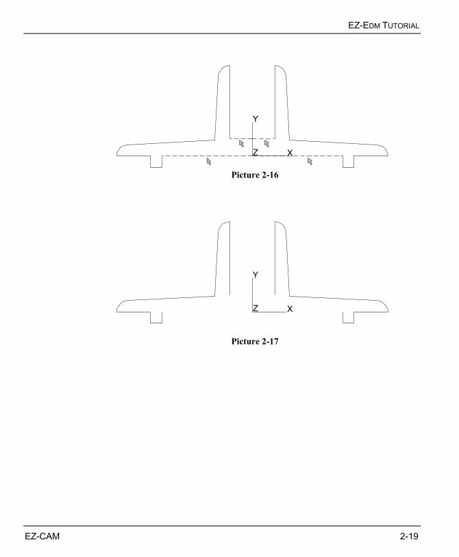
3. Click on the positions / elements shown in Picture 2-16. The selected elements are
highlighted. At the end press ENTER to confirm the delete action. As a result your picture should appear as in Picture 2-17.
EZ-EDM TUTORIAL
EZ-CAM 2-19
Y
Z X
Picture 2-16
Y
Z X
Picture 2-17
CHAPTER 2
2-20 EZ-CAM
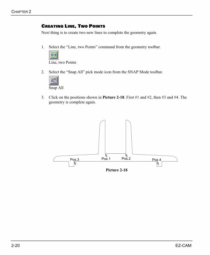
CREATING LINE, TWO POINTS Next thing is to create two new lines to complete the geometry again. 1. Select the “Line, two Points” command from the geometry toolbar.
Line, two Points
2. Select the “Snap All” pick mode icon from the SNAP Mode toolbar.
Snap All
3. Click on the positions shown in Picture 2-18. First #1 and #2, then #3 and #4. The
geometry is complete again.
Pos.1 Pos.2Pos.3 Pos.4
Picture 2-18
EZ-EDM TUTORIAL
EZ-CAM 2-21
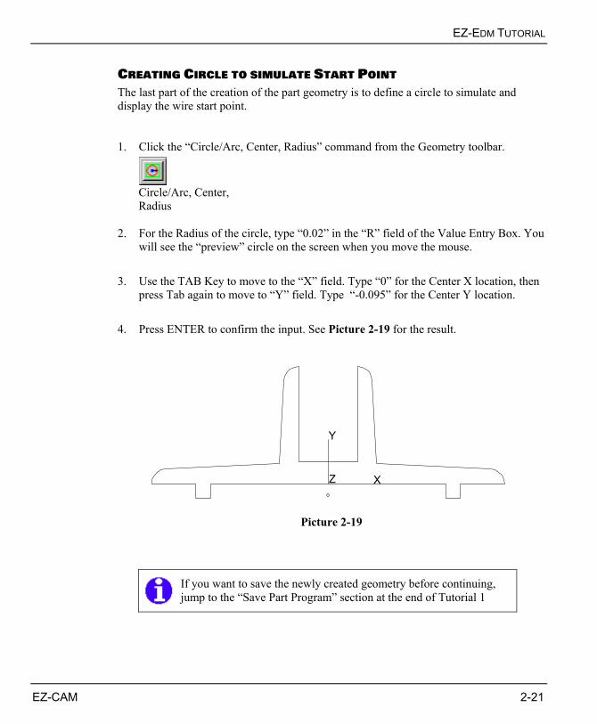
CREATING CIRCLE TO SIMULATE START POINT The last part of the creation of the part geometry is to define a circle to simulate and display the wire start point. 1. Click the “Circle/Arc, Center, Radius” command from the Geometry toolbar.
Circle/Arc, Center, Radius
2. For the Radius of the circle, type “0.02” in the “R” field of the Value Entry Box. You
will see the “preview” circle on the screen when you move the mouse. 3. Use the TAB Key to move to the “X” field. Type “0” for the Center X location, then
press Tab again to move to “Y” field. Type “-0.095” for the Center Y location. 4. Press ENTER to confirm the input. See Picture 2-19 for the result.
Y
Z X
Picture 2-19
If you want to save the newly created geometry before continuing, jump to the “Save Part Program” section at the end of Tutorial 1
CHAPTER 2
2-22 EZ-CAM
THE PATH CURVES Before we continue with the path curve creation we give you a short explanation about what a path curve is. Each Work Step needs a profile or shape the wire will have follow in some way. Therefore a path (curve) has to be assigned to every Work Step following certain rules determined by the selected machining cycle (Contour, Pocketing, etc). For example it is allowed to define an open path when using the “Contour” cycle, whereas a “Pocketing” path has to be closed. A curve can be a straight line, an arc, a spline, or a combination of these things. It may include "rapid" moves, or it may be a single point. The curve does not have to follow any specific rules on its own, but as mentioned above, certain rules determined by the desired operation and the selected machining cycle have to be followed.
You have to assign a unique ID to each curve that is created. You may use your own ID’s or the systems defaults (Crv1, Crv2, etc.), but when working on extensive projects it is always good to use ID’s that can be easily remembered and that reflect the purpose of the curve. Important ! Don’t use space or any other special characters in the curve ID.
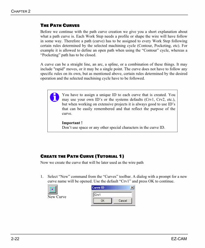
CREATE THE PATH CURVE (TUTORIAL 1) Now we create the curve that will be later used as the wire path 1. Select “New” command from the “Curves” toolbar. A dialog with a prompt for a new
curve name will be opened. Use the default “Crv1” and press OK to continue.
New Curve
EZ-EDM TUTORIAL
EZ-CAM 2-23
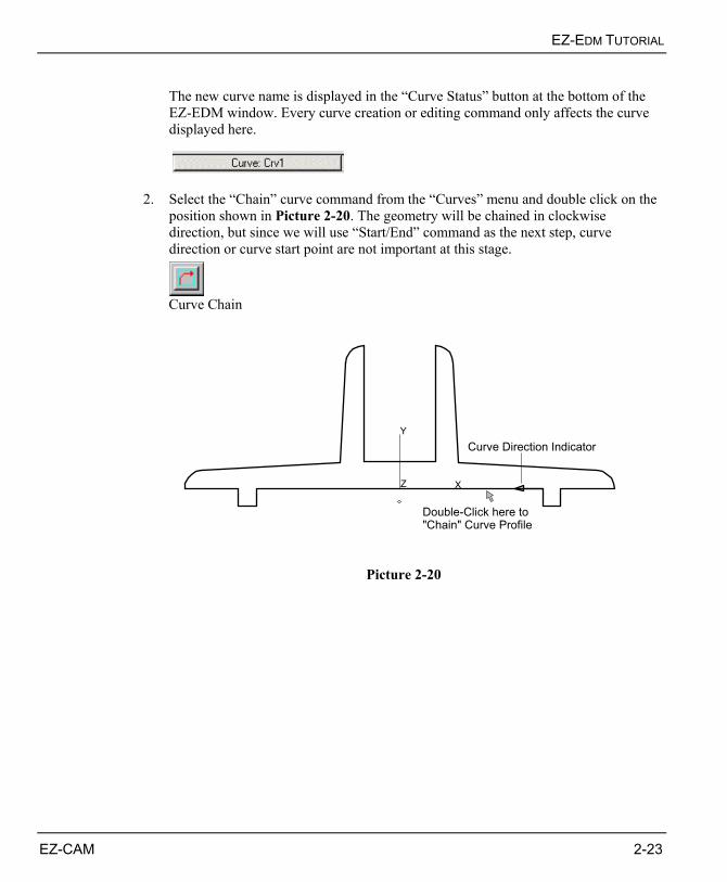
The new curve name is displayed in the “Curve Status” button at the bottom of the EZ-EDM window. Every curve creation or editing command only affects the curve displayed here.
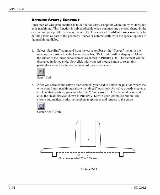
2. Select the “Chain” curve command from the “Curves” menu and double click on the position shown in Picture 2-20. The geometry will be chained in clockwise direction, but since we will use “Start/End” command as the next step, curve direction or curve start point are not important at this stage.
Curve Chain
Y
Z X
Curve Direction Indicator
Double-Click here to"Chain" Curve Profile
Picture 2-20
CHAPTER 2
2-24 EZ-CAM
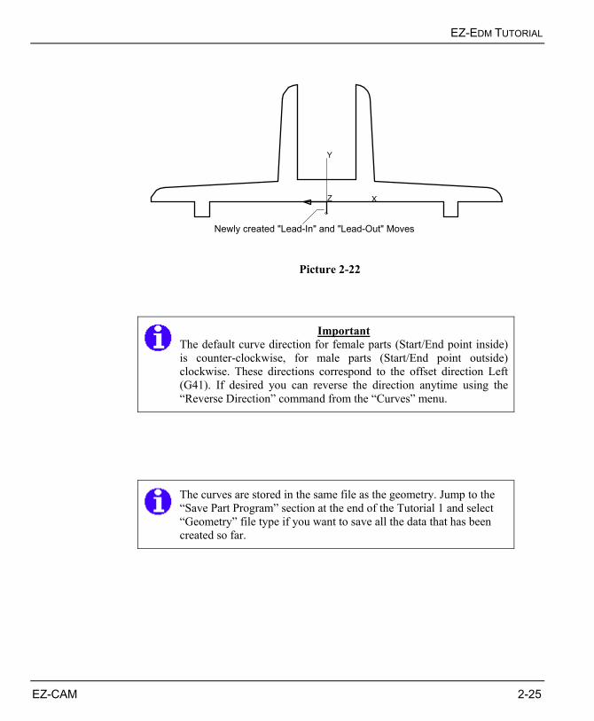
DEFINING START / ENDPOINT Final step of wire path creation is to define the Start/ Endpoint where the wire starts and ends machining. This function is only applicable when you machine a closed shape. In the case of an open profile, you may include the Lead-In and Lead-Out moves manually by defining them as part of the geometry / curve or automatically with the special options in the machining dialog. 1. Select “Start/End” command from the curve toolbar or the “Curves” menu. In the
message bar, just below the Curve Status bar, “Pick Link” will be displayed. Move the cursor to the linear curve element as shown in Picture 2-21. The element will be displayed in dotted style. Now click with your left mouse button to select this particular element as the start element of the current curve.
Start / End
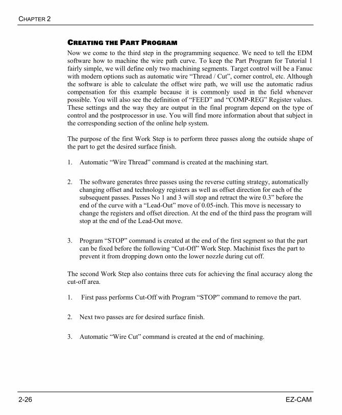
2. After you selected the curve’s start element you need to define the position where the
wire should start machining (also wire “thread” position). As we’ve already created a circle in that position, you can select the “Center Arc/Circle” snap mode icon and click the small circle as shown in Picture 2-22 with your left mouse button. The system automatically adds perpendicular approach and retracts to the curve.
Center Arc / Circle
Y
Z X
Click here to select "Start" Element
Picture 2-21
EZ-EDM TUTORIAL
EZ-CAM 2-25
Y
Z X
Newly created "Lead-In" and "Lead-Out" Moves
Picture 2-22
Important
The default curve direction for female parts (Start/End point inside) is counter-clockwise, for male parts (Start/End point outside) clockwise. These directions correspond to the offset direction Left (G41). If desired you can reverse the direction anytime using the “Reverse Direction” command from the “Curves” menu.
The curves are stored in the same file as the geometry. Jump to the “Save Part Program” section at the end of the Tutorial 1 and select “Geometry” file type if you want to save all the data that has been created so far.
CHAPTER 2
2-26 EZ-CAM
CREATING THE PART PROGRAM Now we come to the third step in the programming sequence. We need to tell the EDM software how to machine the wire path curve. To keep the Part Program for Tutorial 1 fairly simple, we will define only two machining segments. Target control will be a Fanuc with modern options such as automatic wire “Thread / Cut”, corner control, etc. Although the software is able to calculate the offset wire path, we will use the automatic radius compensation for this example because it is commonly used in the field whenever possible. You will also see the definition of “FEED” and “COMP-REG” Register values. These settings and the way they are output in the final program depend on the type of control and the postprocessor in use. You will find more information about that subject in the corresponding section of the online help system. The purpose of the first Work Step is to perform three passes along the outside shape of the part to get the desired surface finish. 1. Automatic “Wire Thread” command is created at the machining start. 2. The software generates three passes using the reverse cutting strategy, automatically
changing offset and technology registers as well as offset direction for each of the subsequent passes. Passes No 1 and 3 will stop and retract the wire 0.3” before the end of the curve with a “Lead-Out” move of 0.05-inch. This move is necessary to change the registers and offset direction. At the end of the third pass the program will stop at the end of the Lead-Out move.
3. Program “STOP” command is created at the end of the first segment so that the part
can be fixed before the following “Cut-Off” Work Step. Machinist fixes the part to prevent it from dropping down onto the lower nozzle during cut off.
The second Work Step also contains three cuts for achieving the final accuracy along the cut-off area. 1. First pass performs Cut-Off with Program “STOP” command to remove the part. 2. Next two passes are for desired surface finish. 3. Automatic “Wire Cut” command is created at the end of machining.
EZ-EDM TUTORIAL
EZ-CAM 2-27
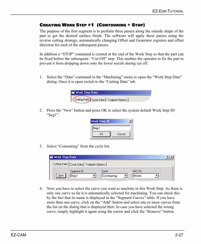
CREATING WORK STEP #1 (CONTOURING + STOP) The purpose of the first segment is to perform three passes along the outside shape of the part to get the desired surface finish. The software will apply these passes using the reverse cutting strategy, automatically changing Offset and Generator registers and offset direction for each of the subsequent passes. In addition a “STOP” command is created at the end of the Work Step so that the part can be fixed before the subsequent “Cut-Off” step. This enables the operator to fix the part to prevent it from dropping down onto the lower nozzle during cut off. 1. Select the “Data” command in the “Machining” menu to open the “Work Step Data”
dialog. Once it is open switch to the “Cutting Data” tab.
2. Press the “New” button and press OK to select the system default Work Step ID
“Seg1”.
3. Select “Contouring” from the cycle list.
4. Now you have to select the curve you want to machine in this Work Step. As there is
only one curve so far it is automatically selected for machining. You can check this by the fact that its name is displayed in the “Segment Curves” table. If you have more than one curve, click on the “Add” button and select one or more curves from the list on the dialog that is displayed then. In case you have selected the wrong curve, simply highlight it again using the cursor and click the “Remove” button.
CHAPTER 2
2-28 EZ-CAM
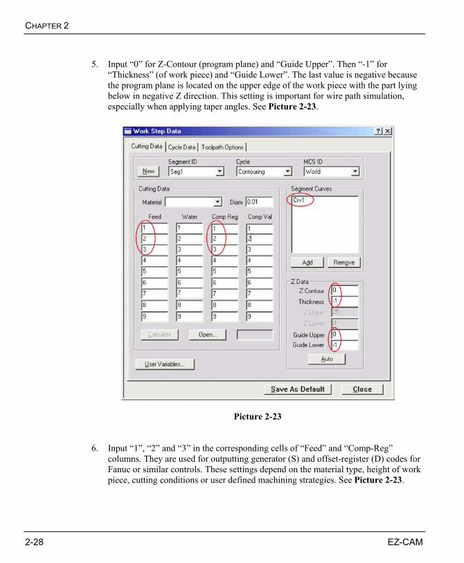
5. Input “0” for Z-Contour (program plane) and “Guide Upper”. Then “-1” for
“Thickness” (of work piece) and “Guide Lower”. The last value is negative because the program plane is located on the upper edge of the work piece with the part lying below in negative Z direction. This setting is important for wire path simulation, especially when applying taper angles. See Picture 2-23.
Picture 2-23 6. Input “1”, “2” and “3” in the corresponding cells of “Feed” and “Comp-Reg”
columns. They are used for outputting generator (S) and offset-register (D) codes for Fanuc or similar controls. These settings depend on the material type, height of work piece, cutting conditions or user defined machining strategies. See Picture 2-23.

EZ-EDM TUTORIAL
EZ-CAM 2-29
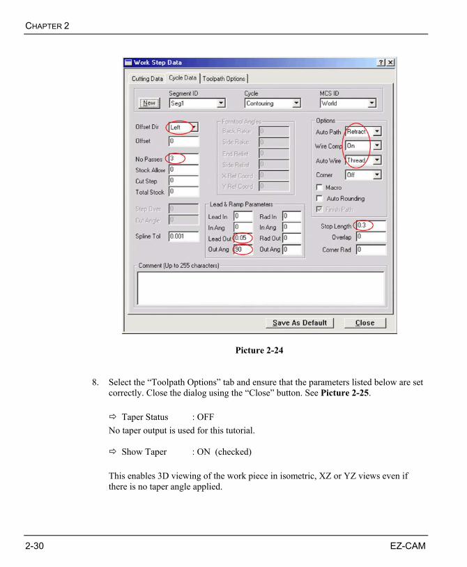
7. Select the “Cycle Data” tab and ensure that the parameters listed below are set
correctly. See Picture 2-24.
Offset Dir. : Left Specifies offset direction for automatic wire compensation (G41, G42, G40). Set to “Left” because our example is a male part with the machined curve defined in clockwise direction.
No Passes : 3 The software will apply these passes using the reverse cutting strategy, automatically changing Offset and Generator registers and offset direction for each of the subsequent passes. Passes No 1 and 3 will stop “0.3” (Stop Length) before the end of the curve with a 0.05-inch (Lead Out Length) lead out move that is needed to switch registers and offset direction. After of the third pass the program will stop at the end of the lead out move.
Auto Path : Retract The software will retract the wire at a given “Stop” distance (Stop Length) before the end of the machined curve(s).
Wire Comp : ON Automatic cutter (wire) compensation ( G41, G42, G40 ) will be used in the machine program. Compensation will be activated on “Lead-In” and cancelled on “Lead-Out” moves automatically.
Auto Wire : Thread This will output a Wire thread command at the beginning of the first machining segment (only necessary for machines with automatic wire thread/cut option).
Stop Length : 0.3 The “Stop Length” and “Overlap” settings are directly related to the “Auto Path” option. The wire will stop 0.3-inch before the part is cut off. At this point the wire will be retracted using the “Lead Out” and “Out-Angle” settings
Lead Out Length : 0.05 / Out Angle : 90
These values specify length and angle of the automatic lead out move that is applied at the “Stop” position.
CHAPTER 2
2-30 EZ-CAM
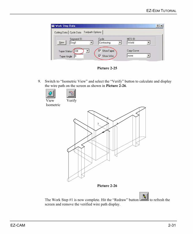
Picture 2-24 8. Select the “Toolpath Options” tab and ensure that the parameters listed below are set
correctly. Close the dialog using the “Close” button. See Picture 2-25.
Taper Status : OFF No taper output is used for this tutorial.
Show Taper : ON (checked)
This enables 3D viewing of the work piece in isometric, XZ or YZ views even if there is no taper angle applied.
EZ-EDM TUTORIAL
EZ-CAM 2-31
Picture 2-25 9. Switch to “Isometric View” and select the “Verify” button to calculate and display
the wire path on the screen as shown in Picture 2-26.
View Isometric
Verify
X
Z
Y
Picture 2-26
The Work Step #1 is now complete. Hit the “Redraw” button to refresh the screen and remove the verified wire path display.
CHAPTER 2
2-32 EZ-CAM
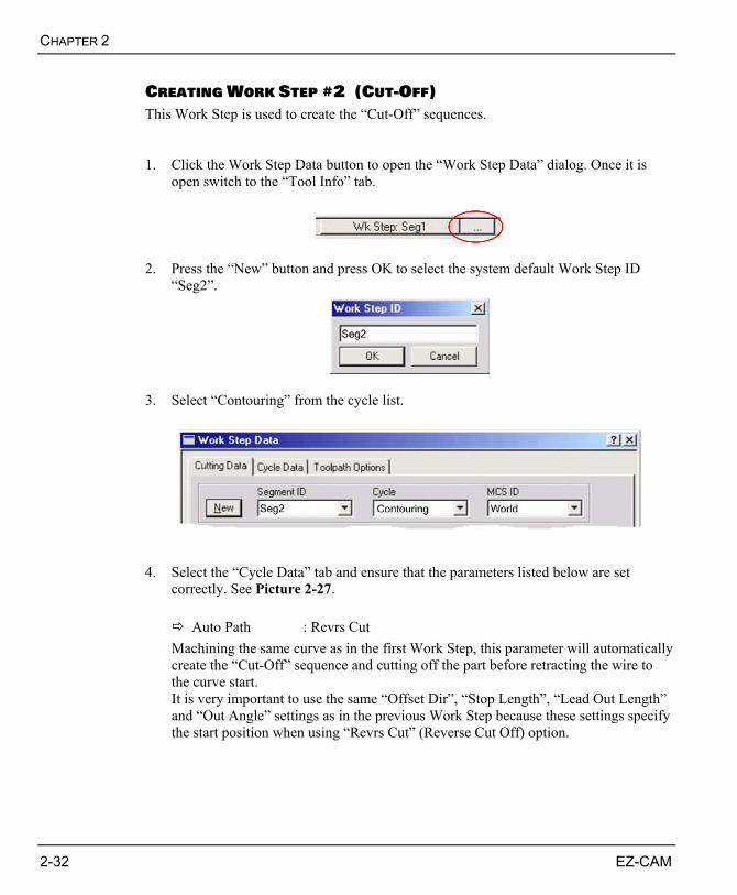
CREATING WORK STEP #2 (CUT-OFF) This Work Step is used to create the “Cut-Off” sequences. 1. Click the Work Step Data button to open the “Work Step Data” dialog. Once it is
open switch to the “Tool Info” tab.
2. Press the “New” button and press OK to select the system default Work Step ID
“Seg2”.
3. Select “Contouring” from the cycle list.
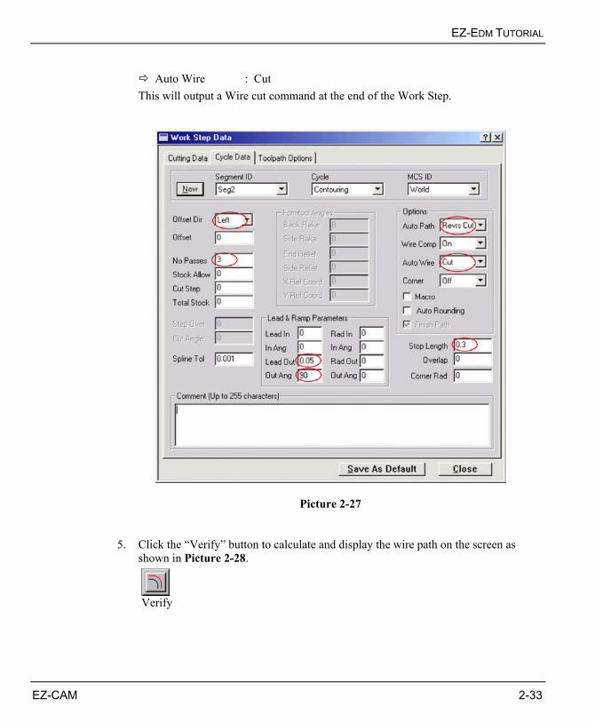
4. Select the “Cycle Data” tab and ensure that the parameters listed below are set
correctly. See Picture 2-27.
Auto Path : Revrs Cut Machining the same curve as in the first Work Step, this parameter will automatically create the “Cut-Off” sequence and cutting off the part before retracting the wire to the curve start. It is very important to use the same “Offset Dir”, “Stop Length”, “Lead Out Length” and “Out Angle” settings as in the previous Work Step because these settings specify the start position when using “Revrs Cut” (Reverse Cut Off) option.
EZ-EDM TUTORIAL
EZ-CAM 2-33
Auto Wire : Cut
This will output a Wire cut command at the end of the Work Step.
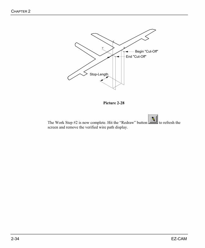
Picture 2-27 5. Click the “Verify” button to calculate and display the wire path on the screen as
shown in Picture 2-28.
Verify
CHAPTER 2
2-34 EZ-CAM
X
Z
Y
Begin "Cut-Off"End "Cut-Off"
Stop-Length
Picture 2-28
The Work Step #2 is now complete. Hit the “Redraw” button to refresh the screen and remove the verified wire path display.
EZ-EDM TUTORIAL
EZ-CAM 2-35
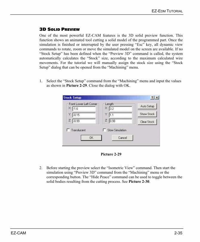
3D SOLID PREVIEW One of the most powerful EZ-CAM features is the 3D solid preview function. This function shows an animated tool cutting a solid model of the programmed part. Once the simulation is finished or interrupted by the user pressing “Esc” key, all dynamic view commands to rotate, zoom or move the simulated model on the screen are available. If no “Stock Setup” has been defined when the “Preview 3D” command is called, the system automatically calculates the “Stock” size, according to the maximum calculated wire movements. For the tutorial we will manually assign the stock size using the “Stock Setup” dialog that can be opened from the “Machining” menu. 1. Select the “Stock Setup” command from the “Machining” menu and input the values
as shown in Picture 2-29. Close the dialog with OK.
Picture 2-29 2. Before starting the preview select the “Isometric View” command. Then start the
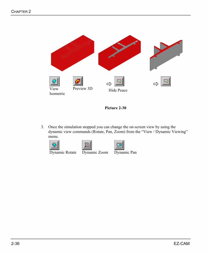
simulation using “Preview 3D” command from the “Machining” menu or the corresponding button. The “Hide Peace” command can be used to toggle between the solid bodies resulting from the cutting process. See Picture 2-30.
CHAPTER 2
2-36 EZ-CAM
View Isometric
Preview 3D
Hide Peace
Picture 2-30 3. Once the simulation stopped you can change the on-screen view by using the
dynamic view commands (Rotate, Pan, Zoom) from the “View / Dynamic Viewing” menu.
Dynamic Rotate Dynamic Zoom Dynamic Pan
EZ-EDM TUTORIAL
EZ-CAM 2-37
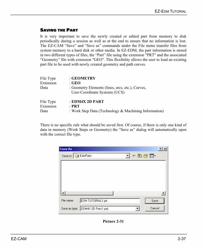
SAVING THE PART It is very important to save the newly created or edited part from memory to disk periodically during a session as well as at the end to ensure that no information is lost. The EZ-CAM “Save” and “Save as” commands under the File menu transfer files from system memory to a hard disk or other media. In EZ-EDM, the part information is stored in two different types of files, the “Part” file using the extension "PRT" and the associated “Geometry” file with extension "GEO". This flexibility allows the user to load an existing part file to be used with newly created geometry and path curves. File Type : GEOMETRY Extension : GEO Data : Geometry Elements (lines, arcs, etc.), Curves,
User-Coordinate Systems (UCS) File Type : EDM4X 2D PART Extension : PRT Data : Work Step Data (Technology & Machining Information) There is no specific rule what should be saved first. Of course, if there is only one kind of data in memory (Work Steps or Geometry) the “Save as” dialog will automatically open with the correct file type.
Picture 2-31
CHAPTER 2
2-38 EZ-CAM
1. Select “Save as” command from the “File” menu. 2. Select the appropriate drive and folder where the geometry and part files should be
stored. You can use the “EZCAMW \ EDMPARTS” folder that was automatically created by the setup routine.
3. Select “Geometry (*.GEO)” from the “Save as type” list box to store the geometry
data. 4. Type the new filename “Edm-Tutorial1” in the “File Name” box and click the “Save”
button. The file extension is added automatically. 5. To store the machining information (Work Step Data) select “EDM4X 2D Part
(*.PRT)” from the “Save as type” list box and click “Save” again.
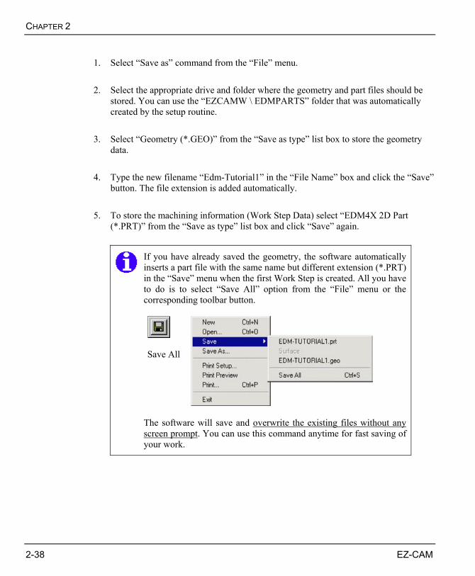
If you have already saved the geometry, the software automatically inserts a part file with the same name but different extension (*.PRT) in the “Save” menu when the first Work Step is created. All you have to do is to select “Save All” option from the “File” menu or the corresponding toolbar button.
Save All
The software will save and overwrite the existing files without any screen prompt. You can use this command anytime for fast saving of your work.
EZ-EDM TUTORIAL
EZ-CAM 2-39
CREATING CNC CODE Now that the part program has been created, it must be converted to run on a NC control by running the “Post” command with the appropriate “Post-Processor” for your machine.
The CNC data file or “Post-Processor” is used as a "template" to format the part program data file that was created in EZ-Turn. This template consists of program formats (e.g., TOOL CHANGE, LINEAR MOVE, RAPID MOVE, etc.) that determine the structure of a part program for a specific CNC. To create or edit a “Post-Processor” a special editor called “EBuild” is required.
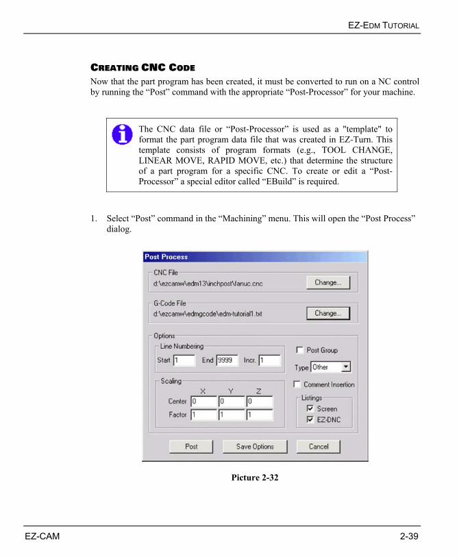
1. Select “Post” command in the “Machining” menu. This will open the “Post Process”
dialog.
Picture 2-32
CHAPTER 2
2-40 EZ-CAM
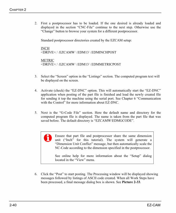
2. First a postprocessor has to be loaded. If the one desired is already loaded and
displayed in the section “CNC-File” continue to the next step. Otherwise use the “Change” button to browse your system for a different postprocessor. Standard postprocessor directories created by the EZCAM setup: INCH <DRIVE>: \ EZCAMW \ EDM13 \ EDMINCHPOST METRIC <DRIVE>: \ EZCAMW \ EDM13 \ EDMMETRICPOST
3. Select the “Screen” option in the “Listings” section. The computed program text will
be displayed on the screen. 4. Activate (check) the “EZ-DNC” option. This will automatically start the “EZ-DNC”
application when posting of the part file is finished and load the newly created file for sending it top the machine using the serial port. See Chapter 6 “Communication with the Control” for more information about EZ-DNC.
5. Next is the “G-Code File” section. Here the default name and directory for the
computed program file is displayed. The name is taken from the part file that was saved before. The default directory is “EZCAMW\EDMGCODE”.
Ensure that part file and postprocessor share the same dimension unit (“Inch” for this tutorial). The system will generate a “Dimension Unit Conflict” message, but then automatically scale the NC-Code according to the dimension specified in the postprocessor. See online help for more information about the “Setup” dialog located in the “View” menu.
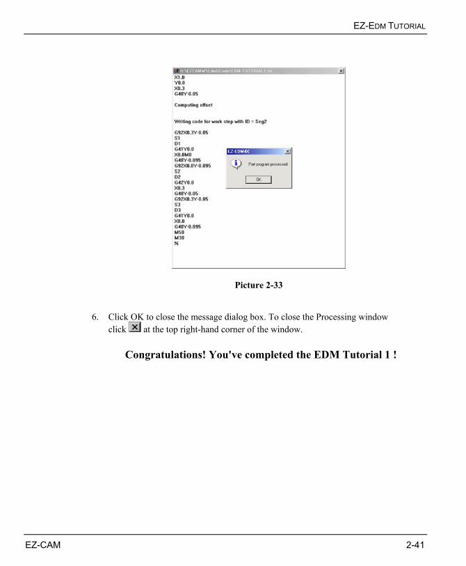
6. Click the “Post” to start posting. The Processing window will be displayed showing
messages followed by listings of ASCII code created. When all Work Steps have been processed, a final message dialog box is shown. See Picture 2-33.
EZ-EDM TUTORIAL
EZ-CAM 2-41
Picture 2-33 6. Click OK to close the message dialog box. To close the Processing window
click at the top right-hand corner of the window.
Congratulations! You've completed the EDM Tutorial 1 !
CHAPTER 2
2-42 EZ-CAM
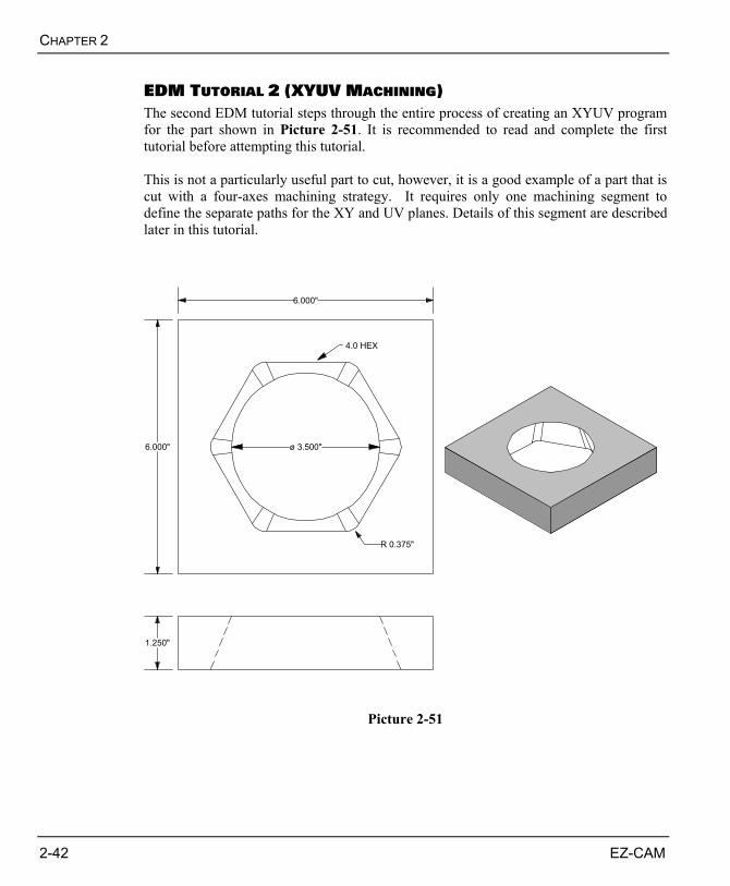
EDM TUTORIAL 2 (XYUV MACHINING) The second EDM tutorial steps through the entire process of creating an XYUV program for the part shown in Picture 2-51. It is recommended to read and complete the first tutorial before attempting this tutorial. This is not a particularly useful part to cut, however, it is a good example of a part that is cut with a four-axes machining strategy. It requires only one machining segment to define the separate paths for the XY and UV planes. Details of this segment are described later in this tutorial.
6.000"
6.000" ø 3.500"
R 0.375"
1.250"
4.0 HEX
Picture 2-51
EZ-EDM TUTORIAL
EZ-CAM 2-43
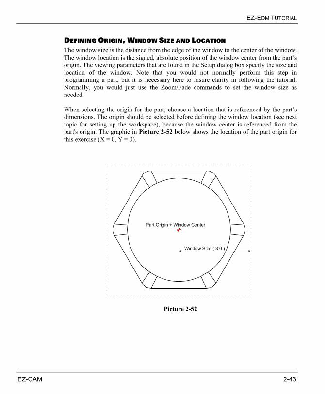
DEFINING ORIGIN, WINDOW SIZE AND LOCATION The window size is the distance from the edge of the window to the center of the window. The window location is the signed, absolute position of the window center from the part’s origin. The viewing parameters that are found in the Setup dialog box specify the size and location of the window. Note that you would not normally perform this step in programming a part, but it is necessary here to insure clarity in following the tutorial. Normally, you would just use the Zoom/Fade commands to set the window size as needed. When selecting the origin for the part, choose a location that is referenced by the part’s dimensions. The origin should be selected before defining the window location (see next topic for setting up the workspace), because the window center is referenced from the part's origin. The graphic in Picture 2-52 below shows the location of the part origin for this exercise (X = 0, Y = 0).
Window Size ( 3.0 )
Part Origin + Window Center
Picture 2-52
CHAPTER 2
2-44 EZ-CAM
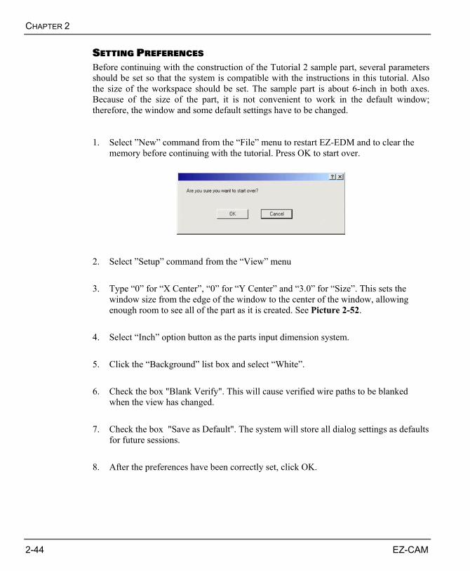
SETTING PREFERENCES Before continuing with the construction of the Tutorial 2 sample part, several parameters should be set so that the system is compatible with the instructions in this tutorial. Also the size of the workspace should be set. The sample part is about 6-inch in both axes. Because of the size of the part, it is not convenient to work in the default window; therefore, the window and some default settings have to be changed. 1. Select ”New” command from the “File” menu to restart EZ-EDM and to clear the
memory before continuing with the tutorial. Press OK to start over.
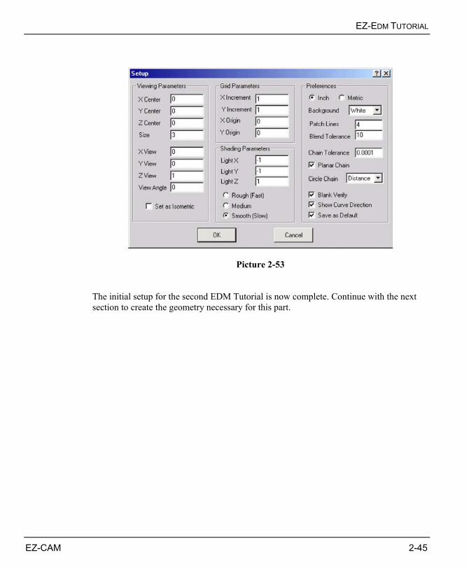
2. Select ”Setup” command from the “View” menu 3. Type “0” for “X Center”, “0” for “Y Center” and “3.0” for “Size”. This sets the
window size from the edge of the window to the center of the window, allowing enough room to see all of the part as it is created. See Picture 2-52.
4. Select “Inch” option button as the parts input dimension system. 5. Click the “Background” list box and select “White”. 6. Check the box "Blank Verify". This will cause verified wire paths to be blanked
when the view has changed. 7. Check the box "Save as Default". The system will store all dialog settings as defaults
for future sessions. 8. After the preferences have been correctly set, click OK.
EZ-EDM TUTORIAL
EZ-CAM 2-45
Picture 2-53 The initial setup for the second EDM Tutorial is now complete. Continue with the next section to create the geometry necessary for this part.
CHAPTER 2
2-46 EZ-CAM
THE PART GEOMETRY Now that the view port has been adjusted to accommodate the part, the creation of the part can begin. This involves creating geometry that is used to define the wire paths for machining the part. The geometry is created first, so that the process of creating the wire paths is greatly simplified.
X-Y View If it’s not already the case, click the “X-Y View” button to change the view to X-Y
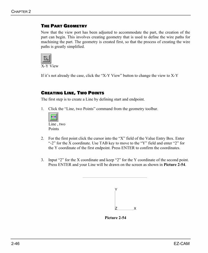
CREATING LINE, TWO POINTS The first step is to create a Line by defining start and endpoint. 1. Click the “Line, two Points” command from the geometry toolbar.
Line , two Points
2. For the first point click the cursor into the “X” field of the Value Entry Box. Enter
“-2” for the X coordinate. Use TAB key to move to the “Y” field and enter “2” for the Y coordinate of the first endpoint. Press ENTER to confirm the coordinates.
3. Input “2” for the X coordinate and keep “2” for the Y coordinate of the second point.
Press ENTER and your Line will be drawn on the screen as shown in Picture 2-54.
Y
Z X
Picture 2-54
EZ-EDM TUTORIAL
EZ-CAM 2-47
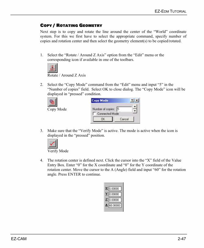
COPY / ROTATING GEOMETRY Next step is to copy and rotate the line around the center of the “World” coordinate system. For this we first have to select the appropriate command, specify number of copies and rotation center and then select the geometry element(s) to be copied/rotated. 1. Select the “Rotate / Around Z Axis” option from the “Edit” menu or the
corresponding icon if available in one of the toolbars.
Rotate / Around Z Axis
2. Select the “Copy Mode” command from the “Edit” menu and input “5” in the “Number of copies” field. Select OK to close dialog. The “Copy Mode” icon will be displayed in “pressed” condition.
Copy Mode
3. Make sure that the “Verify Mode” is active. The mode is active when the icon is
displayed in the “pressed” position.
Verify Mode
4. The rotation center is defined next. Click the cursor into the “X” field of the Value
Entry Box. Enter “0” for the X coordinate and “0” for the Y coordinate of the rotation center. Move the cursor to the A (Angle) field and input “60” for the rotation angle. Press ENTER to continue.
CHAPTER 2
2-48 EZ-CAM
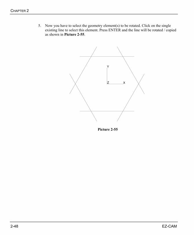
5. Now you have to select the geometry element(s) to be rotated. Click on the single
existing line to select this element. Press ENTER and the line will be rotated / copied as shown in Picture 2-55.
Y
Z X
Picture 2-55
EZ-EDM TUTORIAL
EZ-CAM 2-49
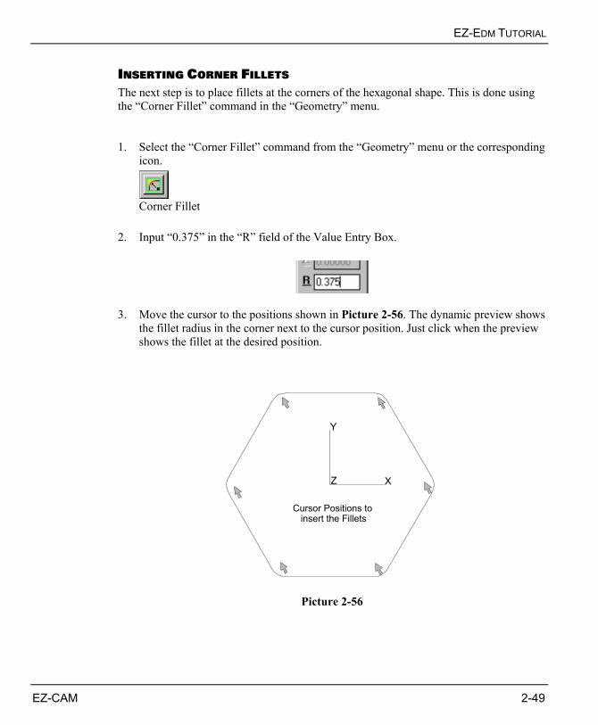
INSERTING CORNER FILLETS The next step is to place fillets at the corners of the hexagonal shape. This is done using the “Corner Fillet” command in the “Geometry” menu. 1. Select the “Corner Fillet” command from the “Geometry” menu or the corresponding
icon.
Corner Fillet
2. Input “0.375” in the “R” field of the Value Entry Box.
3. Move the cursor to the positions shown in Picture 2-56. The dynamic preview shows
the fillet radius in the corner next to the cursor position. Just click when the preview shows the fillet at the desired position.
Y
Z X
Cursor Positions to insert the Fillets
Picture 2-56
CHAPTER 2
2-50 EZ-CAM
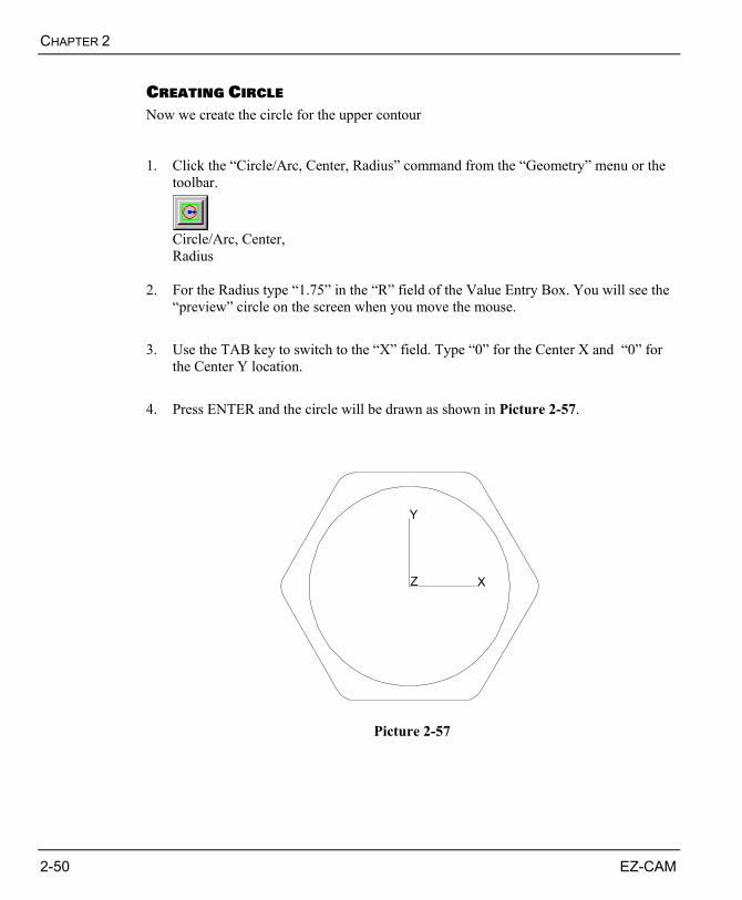
CREATING CIRCLE Now we create the circle for the upper contour 1. Click the “Circle/Arc, Center, Radius” command from the “Geometry” menu or the
toolbar.
Circle/Arc, Center, Radius
2. For the Radius type “1.75” in the “R” field of the Value Entry Box. You will see the
“preview” circle on the screen when you move the mouse. 3. Use the TAB key to switch to the “X” field. Type “0” for the Center X and “0” for
the Center Y location. 4. Press ENTER and the circle will be drawn as shown in Picture 2-57.
Y
Z X
Picture 2-57
EZ-EDM TUTORIAL
EZ-CAM 2-51
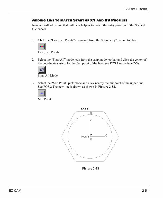
ADDING LINE TO MATCH START OF XY AND UV PROFILES Now we will add a line that will later help us to match the entry position of the XY and UV curves. 1. Click the “Line, two Points” command from the “Geometry” menu / toolbar.
Line, two Points
2. Select the “Snap All” mode icon from the snap mode toolbar and click the center of
the coordinate system for the first point of the line. See POS.1 in Picture 2-58.
Snap All Mode
3. Select the “Mid Point” pick mode and click nearby the midpoint of the upper line.
See POS.2 The new line is drawn as shown in Picture 2-58.
Mid Point
Y
Z XPOS 1
POS 2
Picture 2-58
CHAPTER 2
2-52 EZ-CAM
MATCHING POINTS OF XY AND UV CONTOURS At a later stage two curves have to be created to specify the wire path for a four-axes XYUV cycle. One for the UV upper profile and one for the XY lower profile. The points on both curves have to be matched so that the wire cuts along corresponding moves on each path. Otherwise, the finished part may take a “twisted” look. Following two rules in defining the curves can help preventing this kind of error. First, make sure that the same numbers of points exist in both curves. The system will automatically correct for an unequal number of points using its auto matching function, however, this may introduce undesired effects. The second rule is to make sure that the points are spaced evenly along each path. This tutorial shows one way to accomplish this.
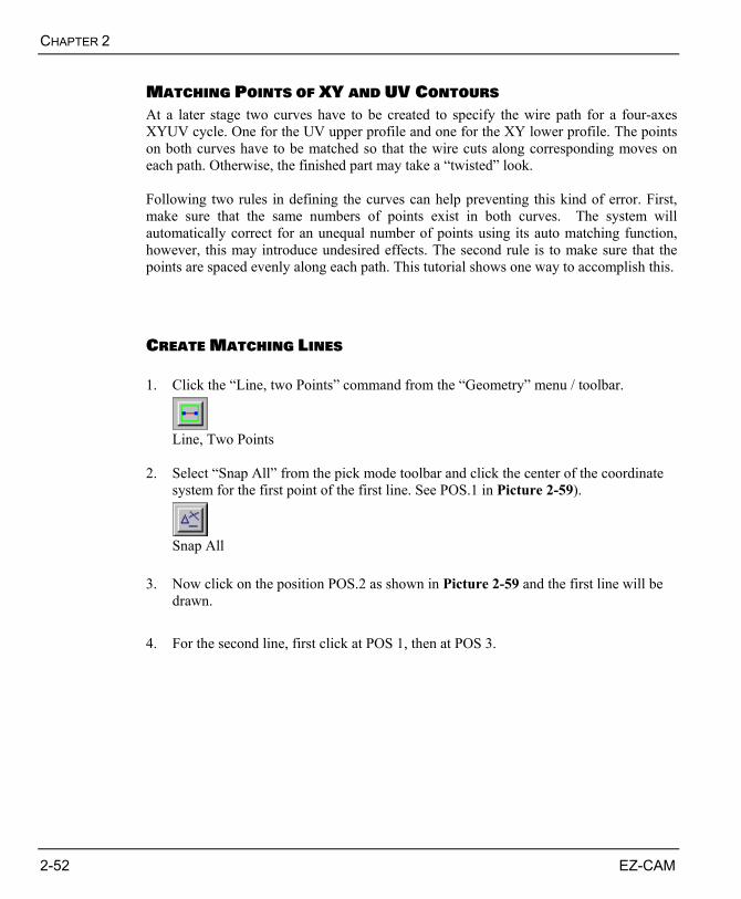
CREATE MATCHING LINES 1. Click the “Line, two Points” command from the “Geometry” menu / toolbar.
Line, Two Points
2. Select “Snap All” from the pick mode toolbar and click the center of the coordinate
system for the first point of the first line. See POS.1 in Picture 2-59).
Snap All
3. Now click on the position POS.2 as shown in Picture 2-59 and the first line will be
drawn. 4. For the second line, first click at POS 1, then at POS 3.
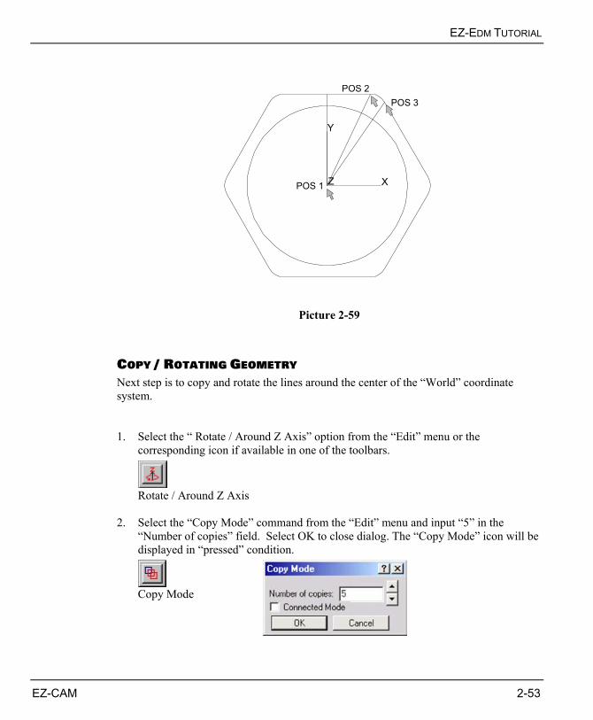
EZ-EDM TUTORIAL
EZ-CAM 2-53
Y
Z XPOS 1
POS 2POS 3
Picture 2-59
COPY / ROTATING GEOMETRY Next step is to copy and rotate the lines around the center of the “World” coordinate system. 1. Select the “ Rotate / Around Z Axis” option from the “Edit” menu or the
corresponding icon if available in one of the toolbars.
Rotate / Around Z Axis
2. Select the “Copy Mode” command from the “Edit” menu and input “5” in the
“Number of copies” field. Select OK to close dialog. The “Copy Mode” icon will be displayed in “pressed” condition.
Copy Mode
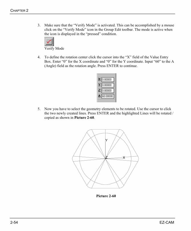
CHAPTER 2
2-54 EZ-CAM
3. Make sure that the “Verify Mode” is activated. This can be accomplished by a mouse
click on the “Verify Mode” icon in the Group Edit toolbar. The mode is active when the icon is displayed in the “pressed” condition.
Verify Mode
4. To define the rotation center click the cursor into the “X” field of the Value Entry
Box. Enter “0” for the X coordinate and “0” for the Y coordinate. Input “60” to the A (Angle) field as the rotation angle. Press ENTER to continue.
5. Now you have to select the geometry elements to be rotated. Use the cursor to click
the two newly created lines. Press ENTER and the highlighted Lines will be rotated / copied as shown in Picture 2-60.
Y
Z X
Picture 2-60
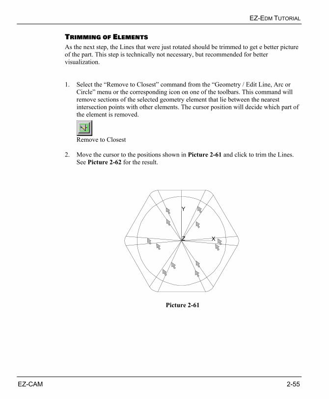
EZ-EDM TUTORIAL
EZ-CAM 2-55
TRIMMING OF ELEMENTS As the next step, the Lines that were just rotated should be trimmed to get e better picture of the part. This step is technically not necessary, but recommended for better visualization. 1. Select the “Remove to Closest” command from the “Geometry / Edit Line, Arc or
Circle” menu or the corresponding icon on one of the toolbars. This command will remove sections of the selected geometry element that lie between the nearest intersection points with other elements. The cursor position will decide which part of the element is removed.
Remove to Closest
2. Move the cursor to the positions shown in Picture 2-61 and click to trim the Lines.
See Picture 2-62 for the result.
Y
Z X
Picture 2-61
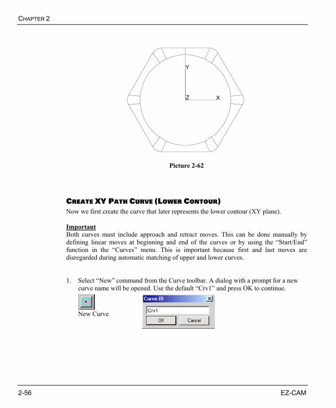
CHAPTER 2
2-56 EZ-CAM
Y
Z X
Picture 2-62
CREATE XY PATH CURVE (LOWER CONTOUR) Now we first create the curve that later represents the lower contour (XY plane). Important Both curves must include approach and retract moves. This can be done manually by defining linear moves at beginning and end of the curves or by using the “Start/End” function in the “Curves” menu. This is important because first and last moves are disregarded during automatic matching of upper and lower curves. 1. Select “New” command from the Curve toolbar. A dialog with a prompt for a new
curve name will be opened. Use the default “Crv1” and press OK to continue.
New Curve
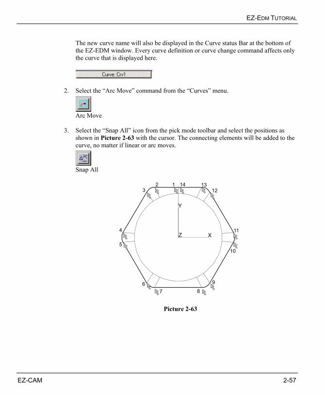
EZ-EDM TUTORIAL
EZ-CAM 2-57
The new curve name will also be displayed in the Curve status Bar at the bottom of the EZ-EDM window. Every curve definition or curve change command affects only the curve that is displayed here.
2. Select the “Arc Move” command from the “Curves” menu.
Arc Move
3. Select the “Snap All” icon from the pick mode toolbar and select the positions as
shown in Picture 2-63 with the cursor. The connecting elements will be added to the curve, no matter if linear or arc moves.
Snap All
Y
Z X
123
4
5
687
9
10
11
14 1312
Picture 2-63
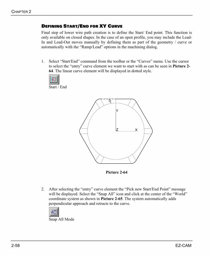
CHAPTER 2
2-58 EZ-CAM
DEFINING START/END FOR XY CURVE Final step of lower wire path creation is to define the Start/ End point. This function is only available on closed shapes. In the case of an open profile, you may include the Lead-In and Lead-Out moves manually by defining them as part of the geometry / curve or automatically with the “Ramp/Lead” options in the machining dialog. 1. Select “Start/End” command from the toolbar or the “Curves” menu. Use the cursor
to select the “entry” curve element we want to start with as can be seen in Picture 2-64. The linear curve element will be displayed in dotted style.
Start / End
Y
Z X
Picture 2-64 2. After selecting the “entry” curve element the “Pick new Start/End Point” message
will be displayed. Select the “Snap All” icon and click at the center of the “World” coordinate system as shown in Picture 2-65. The system automatically adds perpendicular approach and retracts to the curve.
Snap All Mode
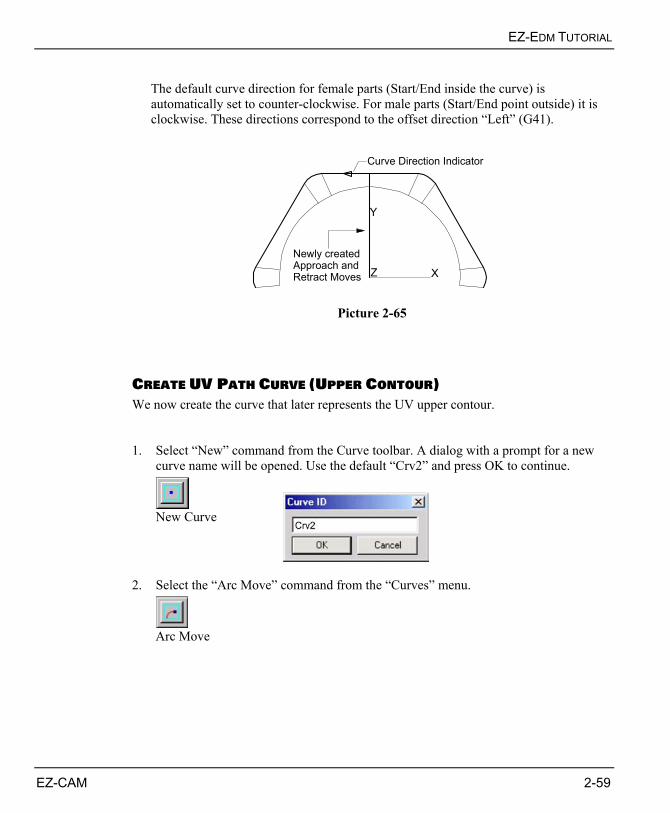
EZ-EDM TUTORIAL
EZ-CAM 2-59
The default curve direction for female parts (Start/End inside the curve) is automatically set to counter-clockwise. For male parts (Start/End point outside) it is clockwise. These directions correspond to the offset direction “Left” (G41).
Y
Z X
Newly createdApproach andRetract Moves
Curve Direction Indicator
Picture 2-65
CREATE UV PATH CURVE (UPPER CONTOUR) We now create the curve that later represents the UV upper contour. 1. Select “New” command from the Curve toolbar. A dialog with a prompt for a new
curve name will be opened. Use the default “Crv2” and press OK to continue.
New Curve
2. Select the “Arc Move” command from the “Curves” menu.
Arc Move
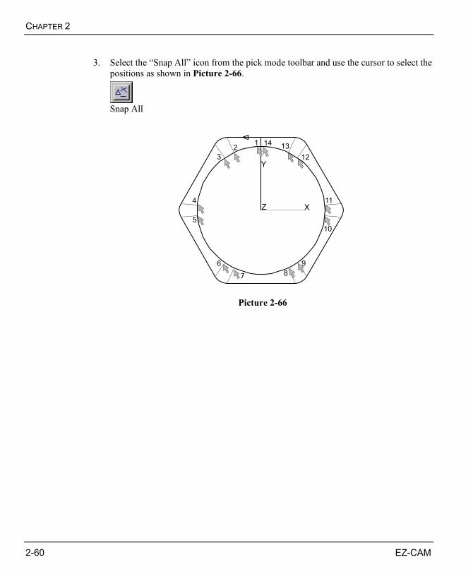
CHAPTER 2
2-60 EZ-CAM
3. Select the “Snap All” icon from the pick mode toolbar and use the cursor to select the
positions as shown in Picture 2-66.
Snap All
Y
Z X
123
4
5
687
9
10
11
14 1312
Picture 2-66
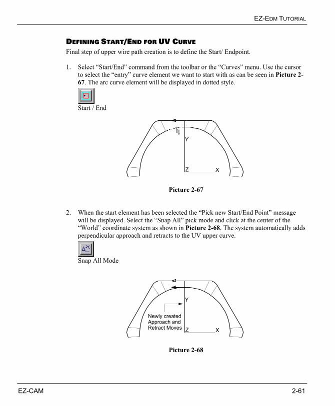
EZ-EDM TUTORIAL
EZ-CAM 2-61
DEFINING START/END FOR UV CURVE Final step of upper wire path creation is to define the Start/ Endpoint. 1. Select “Start/End” command from the toolbar or the “Curves” menu. Use the cursor
to select the “entry” curve element we want to start with as can be seen in Picture 2-67. The arc curve element will be displayed in dotted style.
Start / End
Y
Z X
Picture 2-67
2. When the start element has been selected the “Pick new Start/End Point” message
will be displayed. Select the “Snap All” pick mode and click at the center of the “World” coordinate system as shown in Picture 2-68. The system automatically adds perpendicular approach and retracts to the UV upper curve.
Snap All Mode
Y
Z X
Newly createdApproach andRetract Moves
Picture 2-68
CHAPTER 2
2-62 EZ-CAM
MOVING UV UPPER CONTOUR CURVE Next step is to move the upper contour curve to the desired Z position of 1.25 inch above the lower contour curve. This is because the software uses the curves Z positions to calculate corresponding Z data values for the machining operations. Before moving the upper curve we will switch the screen view to isometric. This gives you a real 3D feeling during the operation. 1. Select “Isometric View” option from the view toolbar or “View / View Control”
menu.
Isometric View
2. Select the “Move” option from the “Edit” menu or the corresponding icon from the
toolbars. Using this option you will move elements from one defined position (Pick “from” point) to a new one (Pick “to” point).
Move
3. Make sure that the “Verify Mode” is activated. This can be accomplished by a mouse
click on the “Verify Mode” icon in the Group Edit toolbar. The mode is active when the icon is displayed in “pressed” condition.
Verify Mode
4. Now we have to define the “Pick from point”. Select the “Snap All” icon from the
toolbar and click on the center of the “World” coordinate system as shown in Picture 2-69.
Snap All Mode
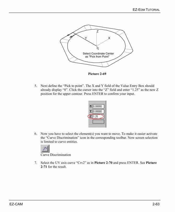
EZ-EDM TUTORIAL
EZ-CAM 2-63
Select Coordinate Center as "Pick from Point"
Y
Z
X
Picture 2-69 5. Next define the “Pick to point”. The X and Y field of the Value Entry Box should
already display “0”. Click the cursor into the “Z” field and enter “1.25” as the new Z position for the upper contour. Press ENTER to confirm your input.
6. Now you have to select the element(s) you want to move. To make it easier activate
the “Curve Discrimination” icon in the corresponding toolbar. Now screen selection is limited to curve entities.
Curve Discrimination
7. Select the UV axis curve “Crv2” as in Picture 2-70 and press ENTER. See Picture
2-71 for the result.
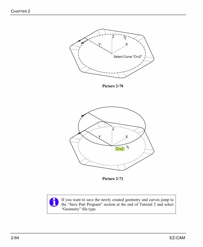
CHAPTER 2
2-64 EZ-CAM
Select Curve "Crv2"
Y
Z
X
Picture 2-70
Y
Z
X
Crv2
Picture 2-71
If you want to save the newly created geometry and curves jump to the “Save Part Program” section at the end of Tutorial 2 and select “Geometry” file type.
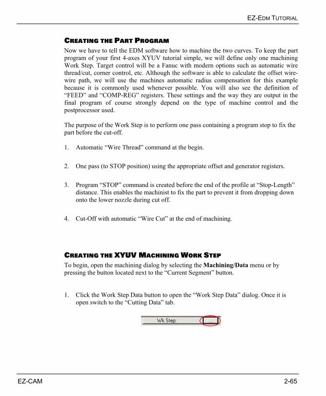
EZ-EDM TUTORIAL
EZ-CAM 2-65
CREATING THE PART PROGRAM Now we have to tell the EDM software how to machine the two curves. To keep the part program of your first 4-axes XYUV tutorial simple, we will define only one machining Work Step. Target control will be a Fanuc with modern options such as automatic wire thread/cut, corner control, etc. Although the software is able to calculate the offset wire-wire path, we will use the machines automatic radius compensation for this example because it is commonly used whenever possible. You will also see the definition of “FEED” and “COMP-REG” registers. These settings and the way they are output in the final program of course strongly depend on the type of machine control and the postprocessor used. The purpose of the Work Step is to perform one pass containing a program stop to fix the part before the cut-off. 1. Automatic “Wire Thread” command at the begin. 2. One pass (to STOP position) using the appropriate offset and generator registers. 3. Program “STOP” command is created before the end of the profile at “Stop-Length”
distance. This enables the machinist to fix the part to prevent it from dropping down onto the lower nozzle during cut off.
4. Cut-Off with automatic “Wire Cut” at the end of machining.
CREATING THE XYUV MACHINING WORK STEP To begin, open the machining dialog by selecting the Machining/Data menu or by pressing the button located next to the “Current Segment” button. 1. Click the Work Step Data button to open the “Work Step Data” dialog. Once it is
open switch to the “Cutting Data” tab.
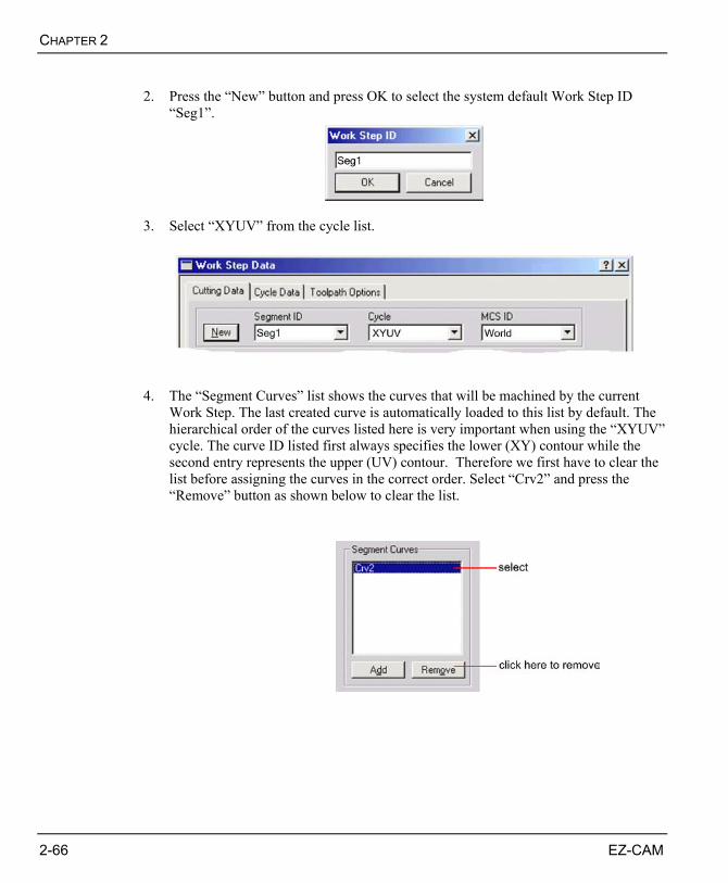
CHAPTER 2
2-66 EZ-CAM
2. Press the “New” button and press OK to select the system default Work Step ID
“Seg1”.
3. Select “XYUV” from the cycle list.
4. The “Segment Curves” list shows the curves that will be machined by the current
Work Step. The last created curve is automatically loaded to this list by default. The hierarchical order of the curves listed here is very important when using the “XYUV” cycle. The curve ID listed first always specifies the lower (XY) contour while the second entry represents the upper (UV) contour. Therefore we first have to clear the list before assigning the curves in the correct order. Select “Crv2” and press the “Remove” button as shown below to clear the list.
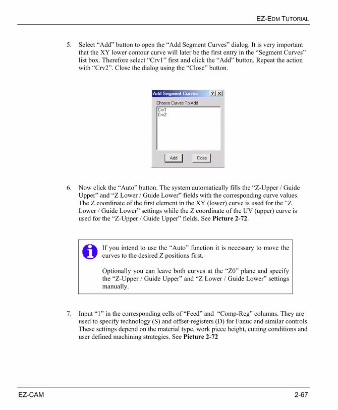
EZ-EDM TUTORIAL
EZ-CAM 2-67
5. Select “Add” button to open the “Add Segment Curves” dialog. It is very important
that the XY lower contour curve will later be the first entry in the “Segment Curves” list box. Therefore select “Crv1” first and click the “Add” button. Repeat the action with “Crv2”. Close the dialog using the “Close” button.
6. Now click the “Auto” button. The system automatically fills the “Z-Upper / Guide
Upper” and “Z Lower / Guide Lower” fields with the corresponding curve values. The Z coordinate of the first element in the XY (lower) curve is used for the “Z Lower / Guide Lower” settings while the Z coordinate of the UV (upper) curve is used for the “Z-Upper / Guide Upper” fields. See Picture 2-72.
If you intend to use the “Auto” function it is necessary to move the curves to the desired Z positions first. Optionally you can leave both curves at the “Z0” plane and specify the “Z-Upper / Guide Upper” and “Z Lower / Guide Lower” settings manually.
7. Input “1” in the corresponding cells of “Feed” and “Comp-Reg” columns. They are
used to specify technology (S) and offset-registers (D) for Fanuc and similar controls. These settings depend on the material type, work piece height, cutting conditions and user defined machining strategies. See Picture 2-72
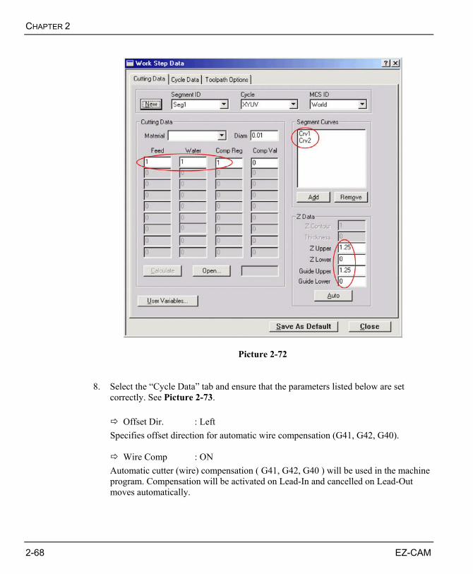
CHAPTER 2
2-68 EZ-CAM
Picture 2-72 8. Select the “Cycle Data” tab and ensure that the parameters listed below are set
correctly. See Picture 2-73.
Offset Dir. : Left Specifies offset direction for automatic wire compensation (G41, G42, G40).
Wire Comp : ON Automatic cutter (wire) compensation ( G41, G42, G40 ) will be used in the machine program. Compensation will be activated on Lead-In and cancelled on Lead-Out moves automatically.
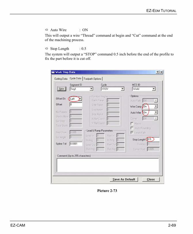
EZ-EDM TUTORIAL
EZ-CAM 2-69
Auto Wire : ON This will output a wire “Thread” command at begin and “Cut” command at the end of the machining process.
Stop Length : 0.5 The system will output a “STOP” command 0.5 inch before the end of the profile to fix the part before it is cut off.
Picture 2-73
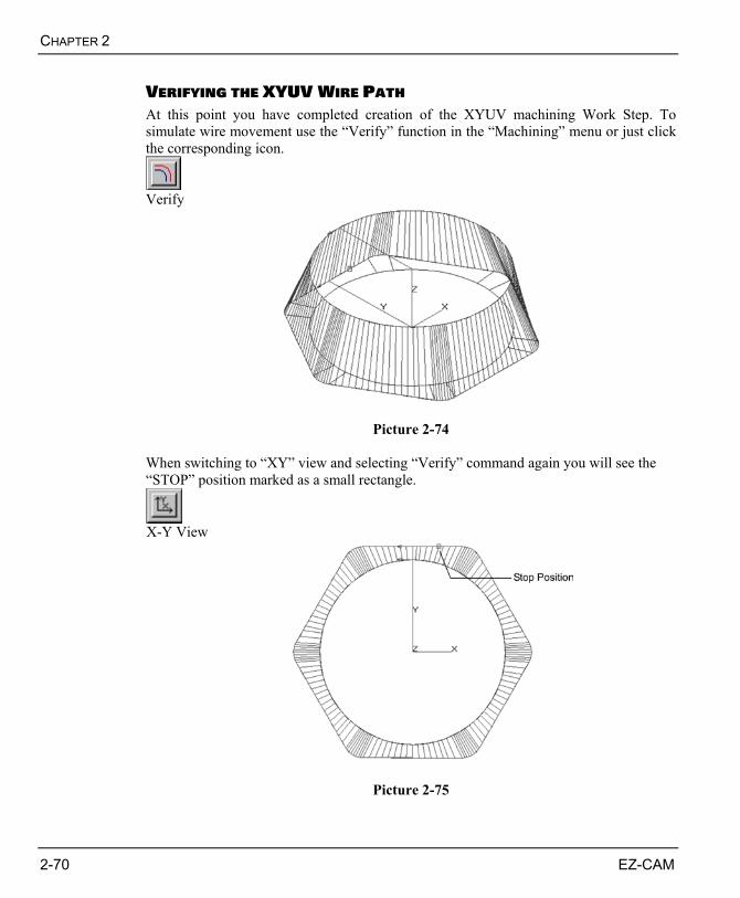
CHAPTER 2
2-70 EZ-CAM
VERIFYING THE XYUV WIRE PATH At this point you have completed creation of the XYUV machining Work Step. To simulate wire movement use the “Verify” function in the “Machining” menu or just click the corresponding icon.
Verify
Picture 2-74 When switching to “XY” view and selecting “Verify” command again you will see the “STOP” position marked as a small rectangle.
X-Y View
Picture 2-75
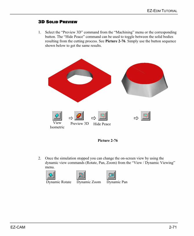
EZ-EDM TUTORIAL
EZ-CAM 2-71
3D SOLID PREVIEW 1. Select the “Preview 3D” command from the “Machining” menu or the corresponding
button. The “Hide Peace” command can be used to toggle between the solid bodies resulting from the cutting process. See Picture 2-76. Simply use the button sequence shown below to get the same results.
View
Isometric
Preview 3D
Hide Peace
Picture 2-76
2. Once the simulation stopped you can change the on-screen view by using the
dynamic view commands (Rotate, Pan, Zoom) from the “View / Dynamic Viewing” menu.
Dynamic Rotate Dynamic Zoom Dynamic Pan
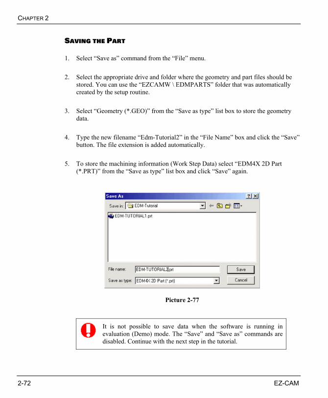
CHAPTER 2
2-72 EZ-CAM
SAVING THE PART 1. Select “Save as” command from the “File” menu. 2. Select the appropriate drive and folder where the geometry and part files should be
stored. You can use the “EZCAMW \ EDMPARTS” folder that was automatically created by the setup routine.
3. Select “Geometry (*.GEO)” from the “Save as type” list box to store the geometry
data. 4. Type the new filename “Edm-Tutorial2” in the “File Name” box and click the “Save”
button. The file extension is added automatically. 5. To store the machining information (Work Step Data) select “EDM4X 2D Part
(*.PRT)” from the “Save as type” list box and click “Save” again.
Picture 2-77
It is not possible to save data when the software is running in evaluation (Demo) mode. The “Save” and “Save as” commands are disabled. Continue with the next step in the tutorial.
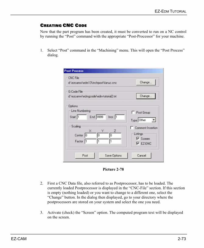
EZ-EDM TUTORIAL
EZ-CAM 2-73
CREATING CNC CODE Now that the part program has been created, it must be converted to run on a NC control by running the “Post” command with the appropriate “Post-Processor” for your machine. 1. Select “Post” command in the “Machining” menu. This will open the “Post Process”
dialog.
Picture 2-78 2. First a CNC Data file, also referred to as Postprocessor, has to be loaded. The
currently loaded Postprocessor is displayed in the “CNC-File” section. If this section is empty (nothing loaded) or you want to change to a different one, select the “Change” button. In the dialog then displayed, go to your directory where the postprocessors are stored on your system and select the one you need.
3. Activate (check) the “Screen” option. The computed program text will be displayed
on the screen.
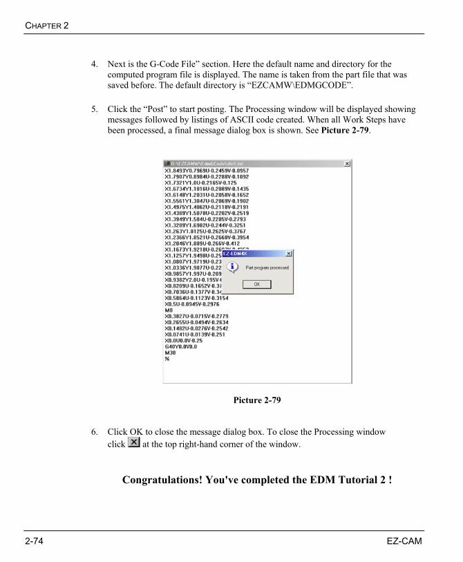
CHAPTER 2
2-74 EZ-CAM
4. Next is the G-Code File” section. Here the default name and directory for the
computed program file is displayed. The name is taken from the part file that was saved before. The default directory is “EZCAMW\EDMGCODE”.
5. Click the “Post” to start posting. The Processing window will be displayed showing
messages followed by listings of ASCII code created. When all Work Steps have been processed, a final message dialog box is shown. See Picture 2-79.
Picture 2-79 6. Click OK to close the message dialog box. To close the Processing window
click at the top right-hand corner of the window.
Congratulations! You've completed the EDM Tutorial 2 !
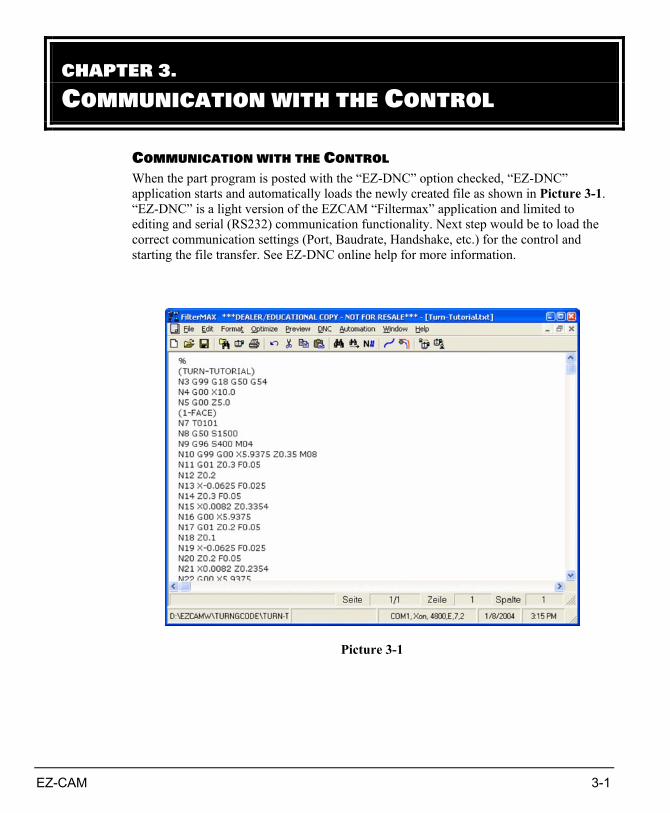
EZ-CAM 3-1
COMMUNICATION WITH THE CONTROL When the part program is posted with the “EZ-DNC” option checked, “EZ-DNC” application starts and automatically loads the newly created file as shown in Picture 3-1. “EZ-DNC” is a light version of the EZCAM “Filtermax” application and limited to editing and serial (RS232) communication functionality. Next step would be to load the correct communication settings (Port, Baudrate, Handshake, etc.) for the control and starting the file transfer. See EZ-DNC online help for more information.
Picture 3-1
CHAPTER 3. COMMUNICATION WITH THE CONTROL
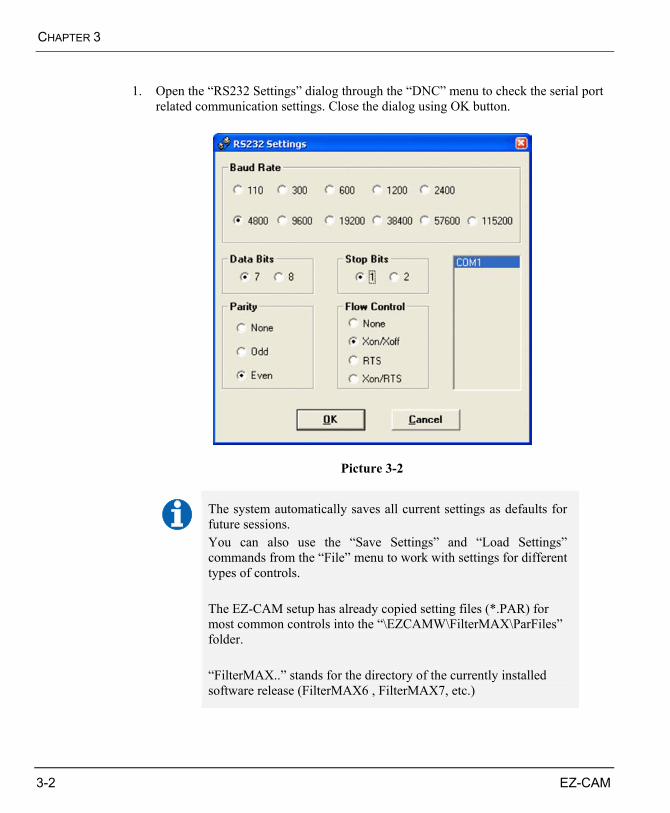
CHAPTER 3
3-2 EZ-CAM
1. Open the “RS232 Settings” dialog through the “DNC” menu to check the serial port
related communication settings. Close the dialog using OK button.
Picture 3-2
The system automatically saves all current settings as defaults for future sessions. You can also use the “Save Settings” and “Load Settings” commands from the “File” menu to work with settings for different types of controls. The EZ-CAM setup has already copied setting files (*.PAR) for most common controls into the “\EZCAMW\FilterMAX\ParFiles” folder. “FilterMAX..” stands for the directory of the currently installed software release (FilterMAX6 , FilterMAX7, etc.)
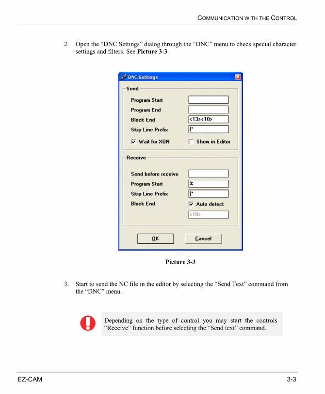
COMMUNICATION WITH THE CONTROL
EZ-CAM 3-3
2. Open the “DNC Settings” dialog through the “DNC” menu to check special character
settings and filters. See Picture 3-3.
Picture 3-3 3. Start to send the NC file in the editor by selecting the “Send Text” command from
the “DNC” menu.
Depending on the type of control you may start the controls “Receive” function before selecting the “Send text” command.
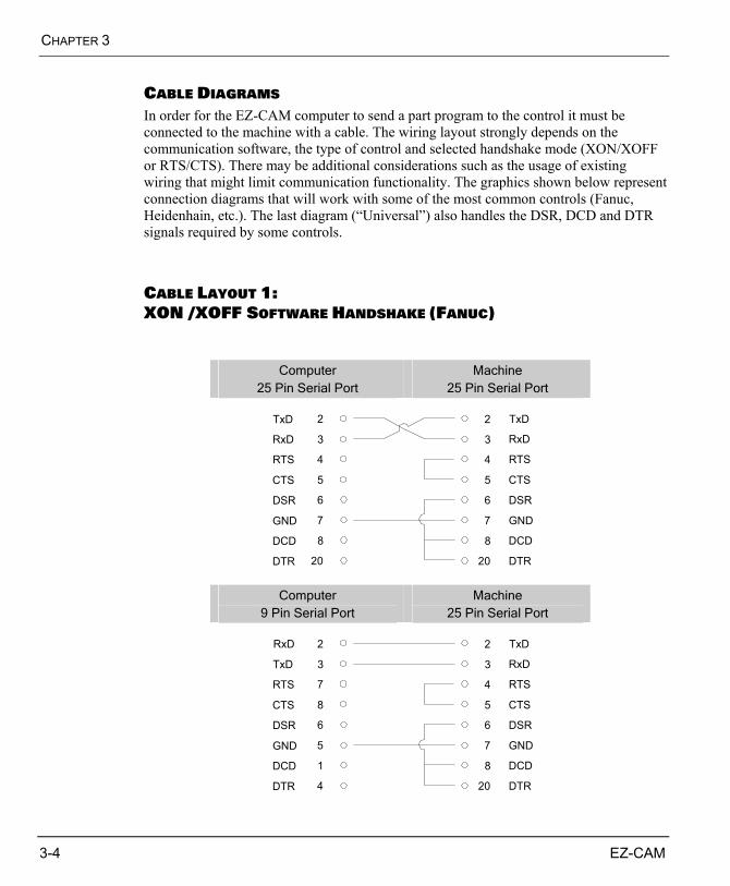
CHAPTER 3
3-4 EZ-CAM
CABLE DIAGRAMS In order for the EZ-CAM computer to send a part program to the control it must be connected to the machine with a cable. The wiring layout strongly depends on the communication software, the type of control and selected handshake mode (XON/XOFF or RTS/CTS). There may be additional considerations such as the usage of existing wiring that might limit communication functionality. The graphics shown below represent connection diagrams that will work with some of the most common controls (Fanuc, Heidenhain, etc.). The last diagram (“Universal”) also handles the DSR, DCD and DTR signals required by some controls.
CABLE LAYOUT 1: XON /XOFF SOFTWARE HANDSHAKE (FANUC)
Computer 25 Pin Serial Port
Machine 25 Pin Serial Port
6
8
20
2
3
4
5
7GND
DCD
DTR
TxD
RxD
RTS
CTS
DSR
GND
DCD
DTR
TxD
RxD
RTS
CTS
DSR6
8
20
2
3
4
5
7
Computer 9 Pin Serial Port
Machine 25 Pin Serial Port
6
1
4
2
3
7
8
5GND
DCD
DTR
TxD
RxD
RTS
CTS
DSR
GND
DCD
DTR
TxD
RxD
RTS
CTS
DSR6
8
20
2
3
4
5
7
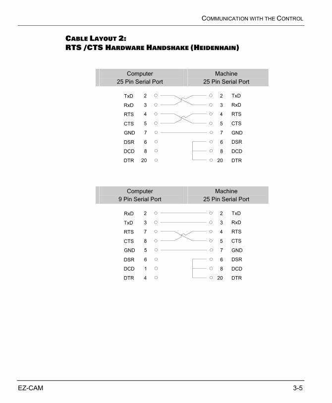
COMMUNICATION WITH THE CONTROL
EZ-CAM 3-5
CABLE LAYOUT 2: RTS /CTS HARDWARE HANDSHAKE (HEIDENHAIN)
Computer 25 Pin Serial Port
Machine 25 Pin Serial Port
6
8
20
2
3
4
5
7GND
DCD
DTR
TxD
RxD
RTS
CTS
DSR
GND
DCD
DTR
TxD
RxD
RTS
CTS
DSR6
8
20
2
3
4
5
7
Computer 9 Pin Serial Port
Machine 25 Pin Serial Port
6
1
4
2
3
7
8
5GND
DCD
DTR
RxD
TxD
RTS
CTS
DSR
GND
DCD
DTR
TxD
RxD
RTS
CTS
DSR6
8
20
2
3
4
5
7
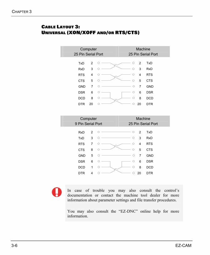
CHAPTER 3
3-6 EZ-CAM
CABLE LAYOUT 3: UNIVERSAL (XON/XOFF AND/OR RTS/CTS)
Computer 25 Pin Serial Port
Machine 25 Pin Serial Port
6
8
20
2
3
4
5
7GND
DCD
DTR
TxD
RxD
RTS
CTS
DSR
GND
DCD
DTR
TxD
RxD
RTS
CTS
DSR6
8
20
2
3
4
5
7
Computer 9 Pin Serial Port
Machine 25 Pin Serial Port
6
1
4
2
3
7
8
5GND
DCD
DTR
RxD
TxD
RTS
CTS
DSR
GND
DCD
DTR
TxD
RxD
RTS
CTS
DSR6
8
20
2
3
4
5
7
In case of trouble you may also consult the control’s documentation or contact the machine tool dealer for more information about parameter settings and file transfer procedures. You may also consult the “EZ-DNC” online help for more information.
![STEP-Compliant CAD/CNC System for Feature-Oriented …cad-journal.net/files/vol_16/CAD_16(2)_2019_358-368.pdfexchange standard between CAD/CAM and CNC machines [12]. However, it is](https://img.pdfslide.us/doc/110x75/6009a2e47a31b278094bbfc7/step-compliant-cadcnc-system-for-feature-oriented-cad-22019358-368pdf-exchange.jpg)