Embed Size (px)
Citation preview

CPU5A Economy Series
125 KHz step frequency, 4 axes.
Card size 100x100mm.
USB 2.0 connection.
100 Mbit Ethernet connection (*).
5 Status LED's.
Full 4 axes interpolation (*).
7 Standard CNC outputs.
0-10V output for spindle speed control.
10 Standard CNC inputs.
Pendant connection with MPG and 2 switches.
Hardware safety watchdog.
SUBD-25 + SUBD-9 connector.
No breakout board needed.
Powered by USB or +5V external.
Field upgradable firmware.
USBCNC software included.
Windows XP, Windows 7.
Runs on single core atom PC.
(*) depending on model Features
Shortest possible CNC production time, especially 3D work, depending on the product, USBCNC can be up to 2 times faster . This is thanks to the advanced Look Ahead Feed Algorithm that works for all motion segments, lines and circles by looking at their curvature and reduce speed only when absolutely necessary.
Simple one screen operation, UI designed for and by professional CNC operators.
Array mode execution for multiple production.
Optimized tooltip feed calculations for 4th axis milling, no tool breakage due to wrong tool-tip feed.
Feed Override control while running 0-300%.
Easy start half way in g-code file, using search method
Slave axes, for systems with dual motors (tandem) on X, Y or Z axis.
Special homing sequence for tandems, sets tandem straight.
Tangential knife, you need to program only X.Y coordinates and the tangential knife follows, also in circles and lifts automatically up when needed.
Backlash compensation.
Spindle proportional ramp-up time.
Collision detection when g-code job is loaded prevents machine damage.
Running time estimation when job is loaded.
Thread cutting (Lathe).
OpenGL graphics allows real-time PAN/ZOOM/ROTATE
G-code is EMC compatible, RS274NGC, can be used with all CAM software's so far.
G-code extensions with IF..THEN, WHILE..ENDWHILE, SUB ENDSUB, GOSUB.
Super long file mode allows endless files, tested with 100.000.000 lines g-code.
User interaction from G-Code with DlgMsg command and a lot more.
Automatic tool change can be programmed entirely in G-code.
Pause, Jog away, resume run in middle of g-code run.
Hand wheel jog with position and velocity mode.
Build in 2D CAM for drilling, engraving, profiling and pocketing, reads DXF and HPGL.
SDK for building customized UI's.

Connections of EdingCNC CPU5A3. CPU5A4 and CPU5A4E
S: SHIELD 25: GND 24: GND 23: GND 22: GND 21: +5V (Solder jumper) 20: +5V (Solder jumper) 19: SPINDEL-PULSE 18: PROBE 17: PWM or 0..10V (JUMPER) 16: OUT WATCHDOG 15: IN HOME4 14: OUT FLOOD
13: IN HOME1 12: IN HOME2 11: IN ESTOP 10: IN HOME3 9: OUT STEP4 8: OUT DIR4 7: OUT STEP3 6: OUT DIR3 5: OUT STEP2 4: OUT DIR2 3: OUT STEP1 2: OUT DIR1 1: OUT TOOL
6: IN HANDWHEEL B 7: +5V 8: GND 9: GND S: SHIELD
5: IN HANDWHEEL A 4: OUT AUX1 3: OUT MIST 2: IN PAUSE 1: IN RUN
74HCT14 outputs for step/direction 15 mA per output source or sink.
Other outputs are open collector transistor outputs 100 mA max current. PWM frequency 5 Khz Charge pump frequency 10 Hz (LED4)
E-Stop input
Other inputs are 74HCT14 inputs. Pull-up to +5V with 10K Filtered with R/C filter

See also the manual about how to use an open collector output. 0..10 Volt output 10 mA for VFD control
Jumper settings
Jumpers
The yellow marked jumpers are the only ones interesting to you. The others should be left untouched.
Lower left (USBPWR) is set if the board is powered by the USB voltage. Remove if you want to power externally. External POWER can be applied on the SUBD 25 connector (PIN 20-21, 22-25). And also on the SUBD 9 connector (PIN 7, 8-9), see table above. (*) These power lines can also be used to drive the step/dir/amp-enable inputs of your drive of needed.
When using the supply lines on the SUBD 25 the solder jumpers on the bottom side must be connected. They are not standard connected because of compatibility with other parallel port based CNC controls where these pins are connected to GND.
This jumper selects the signal on PIN 17 of the DB25. Jumper to the right => PWM out. Jumper to the left => 0-10 Volt out.
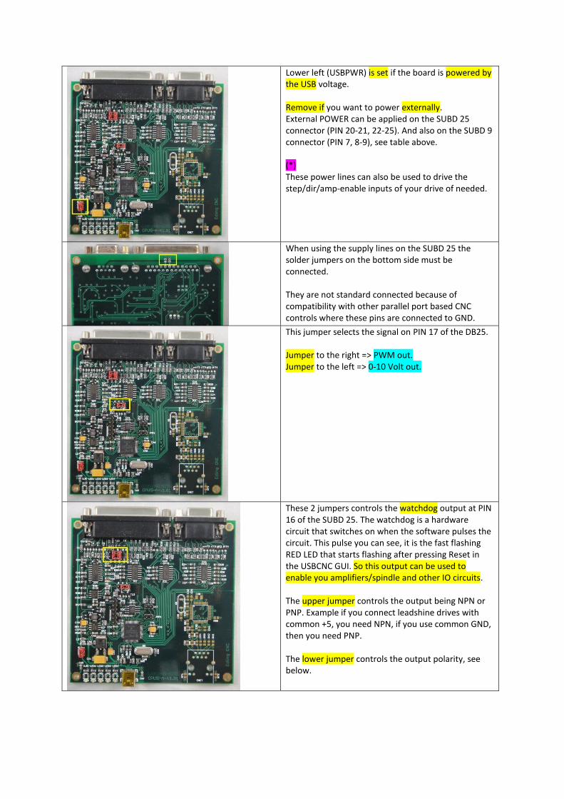
These 2 jumpers controls the watchdog output at PIN 16 of the SUBD 25. The watchdog is a hardware circuit that switches on when the software pulses the circuit. This pulse you can see, it is the fast flashing RED LED that starts flashing after pressing Reset in the USBCNC GUI. So this output can be used to enable you amplifiers/spindle and other IO circuits. The upper jumper controls the output being NPN or PNP. Example if you connect leadshine drives with common +5, you need NPN, if you use common GND, then you need PNP. The lower jumper controls the output polarity, see below.

The details of the watchdog output configuration jumpers. Upper jumper to the right => Open Collector NPN. Use with external supply. Upper jumper to the left => Open Collector PNP (+5V) output. Use with internal +5V supply. Lower jumper to the right =>NPN Active SAFE. PNP Active NOTSAFE. Lower jumper to the left=>NPN Active NOT SAFE. PNP Active SAFE.
This GREEN LED shows the state of the Watchdog. ON => Safe OFF => Not Safe

Connection to the stepper motor or servomotor drive
EXAMPLE1 - USE WATCHDOG TO AMPENABLE FOR LEADSHINE DRIVE (POSITIVE PULSE CONNECTION) The Leadshine drives are OFF when the input is driven, it is opposite of what most of us expect. Upper jumper to the left (PNP), Lower to the right (ON-SAFE) Positive pulse connection does not need the +5V, that is the difference with negative pulse connection.
Pulse Inversion
CPU to drive connections
EXAMPLE2 - USE WATCHDOG TO AMPENABLE FOR LEADSHINE DRIVE (NEGATIVE PULSE CONNECTION) This way of connection is the best choice for 90% of the drives in the market. Upper jumper to the right (NPN). Lower jumper to the left (OFF-NOTSAFE) Negative pulse connection is the standard way to connect this type of drive. It needs the 5 Volt connection terminal. See also(*) above.
Pulse Inversion
CPU to drive connections
REMARK By connecting a drive to the wrong pulse polarity does not harm anything. Nothing will be damaged. The difference is the speed that you will get on the motor. Just try out by inverting the Pulse inversion in the software what gives the highest motor speed. The +5V can be used from Pin20/21 of the 25p D-Connector. For this the 2 solder jumpers on the bottom side must be soldered. Where is X, Y, Z connected to? USBCNC allows variable configurations.

Some customers have X Y Z A Some have X Y Z C Some have X Z A B So the first selected axis in the setup is connected to STEP1/DIR1 the next to STEP2/DIR2 etc.
Connection of the inputs HOME - ESTOP - PAUSE - RUN - HANDWHEEL - SPINDLE-SENSOR
INDUCTIVE HOME SENSORS
NPN Type only! (PNP will blow up the input if the sensor voltage is higher than +5V)
SIMPLE HOME SWITCH
Normally Open Type HomeInputSenseLevel = 0 Normally Closed Type HomeInputSenseLevel = 1
ESTOP
SWITCH
Normally Open EStopInputSenseLevel = 0 Normally Closed EStopInputSenseLevel = 1
RUN SWITCH Any push button switch
Auto detect
PAUSE SWITCH Any push button switch
Normally closed

Handwheel
+5 Volt handwheel
Spindle sensor This is required for Lathe Thread cutting
Ask your dealer
Vishay TCST2103
LED Side:
Connect + of Led with 82 Ohm to +5V.
Connect E to GND.
Output transistor side:
Connect D (Emitter) GND.
Connect + (Collector) to CPU input
The pulse must be >= 1 millisecond long.
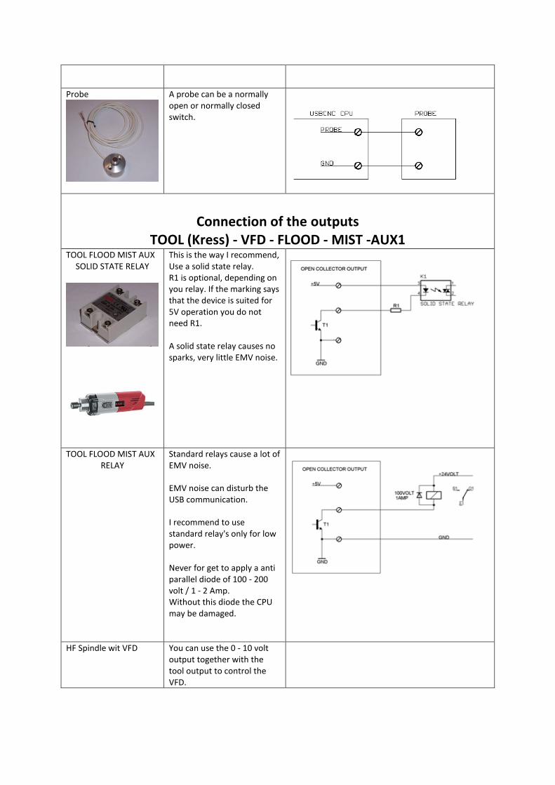
Probe
A probe can be a normally open or normally closed switch.
Connection of the outputs
TOOL (Kress) - VFD - FLOOD - MIST -AUX1
TOOL FLOOD MIST AUX SOLID STATE RELAY
This is the way I recommend, Use a solid state relay. R1 is optional, depending on you relay. If the marking says that the device is suited for 5V operation you do not need R1. A solid state relay causes no sparks, very little EMV noise.
TOOL FLOOD MIST AUX RELAY
Standard relays cause a lot of EMV noise. EMV noise can disturb the USB communication. I recommend to use standard relay's only for low power. Never for get to apply a anti parallel diode of 100 - 200 volt / 1 - 2 Amp. Without this diode the CPU may be damaged.
HF Spindle wit VFD
You can use the 0 - 10 volt output together with the tool output to control the VFD.
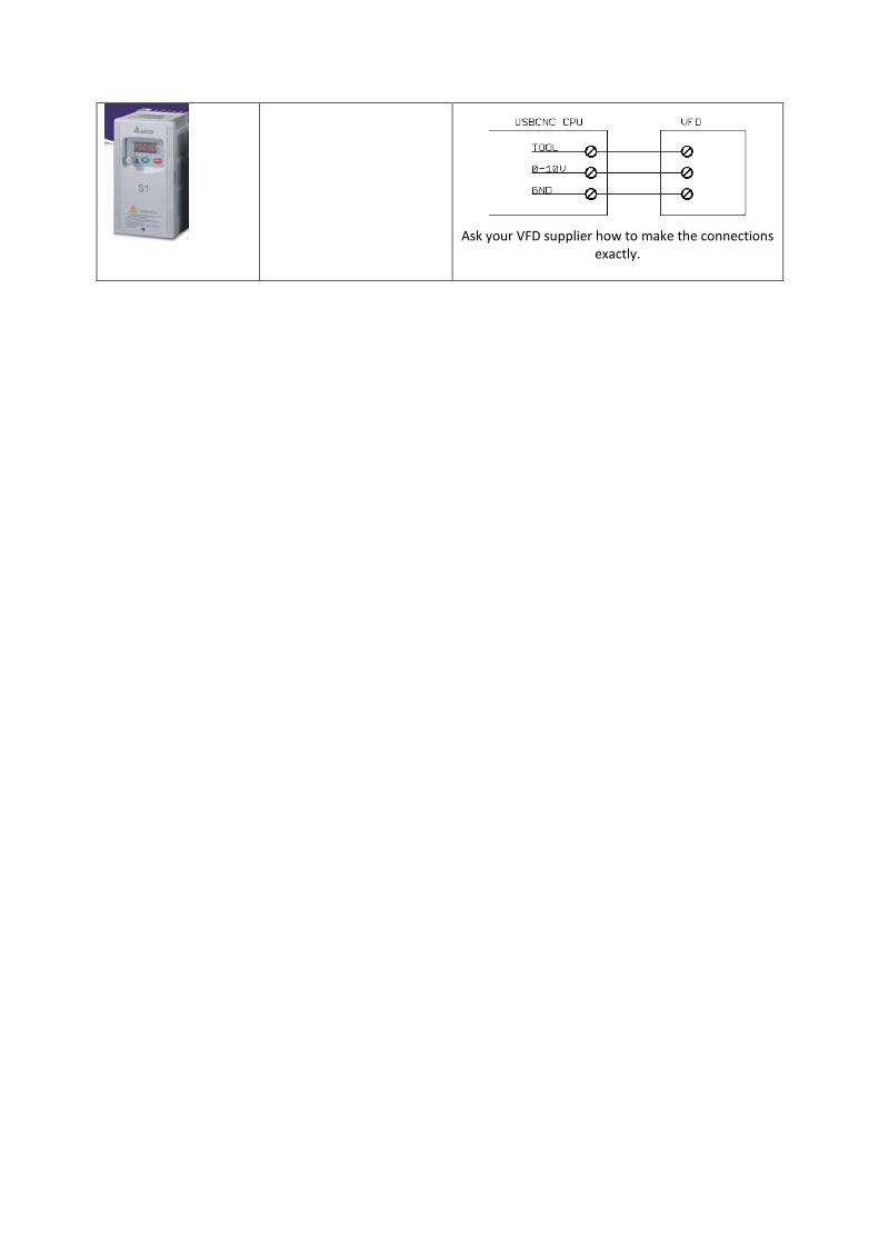
Ask your VFD supplier how to make the connections exactly.

LEDS
The board has 2 pieces of software, 1. Bootloader 2. CNC firmware. The bootloader allows to update the CNC firmware using the PC application “CPU5 Configurator” When the board is powered by +5V, it starts in bootloader mode. After 5 seconds the CNC firmware starts. When the CPU5 Configurator contacts the board in the first 5 seconds after power on (by pressing get version in the app). Update of the CNC firmware is possible. When this does not happen, the bootloader will start the CNC firmware. The bootloader can also be skipped by setting JMP1 jumper, this makes that the CNC firmware starts immediately. The firmware start can be recognized by 10 fast flashes of the first led besides the USB connector.
LED's from left to right Bootloader Mode CNC mode
Blue +5 Volt and CPU 3.3Volt present.
Red Error during programming. Watchdog reset signal, Fast flash pulse, starts when RESET is pressed in the software.
Yellow Alternating flash indicate boot loader active and communication with USB working.
FLASH=> ETHERNET OR USB COMMUNICATION ACTIVE
Green MACHINE ON or System Ready. After Reset is pressed.
Orange Capture status, if on boot loader remains active. See also CPU5 configurator tool.
10 pulses at startup to show CNC firmware starting. On if E-Stop activated. Off if no E-Stop activated.

Enabling a CPU or an Option for a CPU
This is special for CPU5 series, select CPU-OPT in the Setup of the Software
1 you see if the CPU is activated or not, green is enabled, red is not enabled.
2 you check the option that you wish to obtain, if the CPU is not enabled and you wish only to enable
it, no selection here is needed.
3 Put Your name here.
4 Press the button “GetRequestCode”.
5 Copy and paste the request code in your email and send it to the supplier.
Your supplier will send you back an activation code.
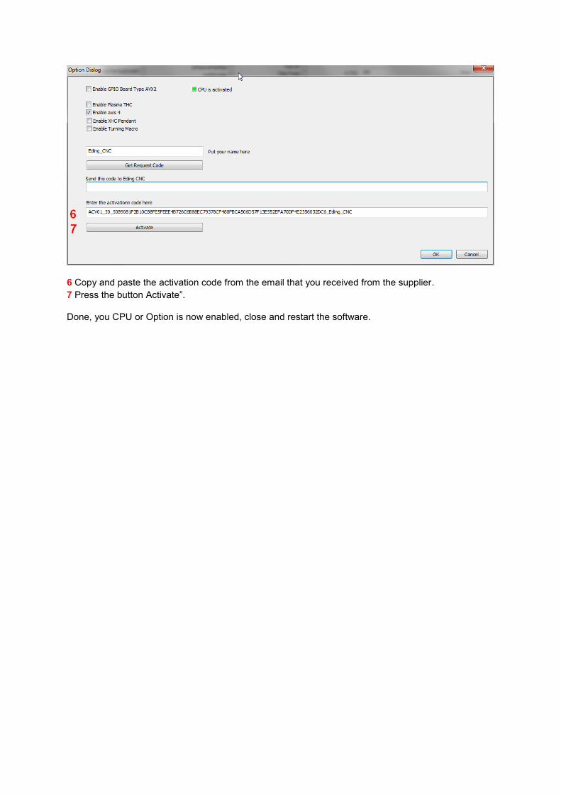
6 Copy and paste the activation code from the email that you received from the supplier.
7 Press the button Activate”.
Done, you CPU or Option is now enabled, close and restart the software.